
45 ASP | FEBRUARY 2023 AUGUST 2023 • VOL. 13, NO. 4 THE TECHNICIAN’S RESOURCE Upgrade your shop with the reliable performance of Bosch Filters. Built for hardworking professionals like you, our filters deliver high-efficiency filtration for oil, air, and cabin applications. Take advantage of our competitive pricing and unlock the benefits of our exclusive eXtra Rewards Program. Earn rewards points for the parts you’re already purchasing! Visit BoschAutoParts.com/WorkshopFilters today and discover a new level of excellence for your shop. Stock your shop. Earn rewards. Start earning rewards today. Register now! ADVERTISEMENT


Here’s how it works. Buy Earn points every time you buy eligible partner products from participating distributors. Earn Opt in to our monthly e-statement and app notifications for exclusive bonus point offers and promotions. Get Use your points for business solutions and consumer products like electronics, household items, travel, event tickets and more. The best part? It’s totally free and easy to sign up. Register now at www.extra-awards.com/registration. Earn eXtra points on Bosch-branded Workshop Filters. YOU BUY THE PARTS, NOW EARN YOUR REWARDS. Start earning rewards today. Register now!
TAKE THE MYSTERY OUT OF WIRING DIAGRAMS
Tips to understand schematics
TOOLS AND EQUIPMENT FOR EV SERVICE

ADDRESSING NO-START ISSUES
VARIABLE VALVE TIMING
AUGUST 2023 • VOL. 13, NO. 4
THE TECHNICIAN’S RESOURCE


2 ASP | AUGUST 2023 TO Professionals Professionals Federated Auto Parts is known for experienced professionals who understand your business and are dedicated to providing unrivaled service to other professionals in the field. Come to Federated for the finest brand name, premium quantity auto parts available and our first-rate professionals. Come to Federated for the Best. www.federatedautoparts.com Known for knowledgeable parts professionals who understand your business, Federated is dedicated to providing service professionals with quality brand name parts, business-building programs, and outstanding customer service to help you grow your business. www.federatedautoparts.com


AUGUST 2023 | ASP 3 Departments STRAIGHT TALK The Internet Know-It-All How to handle a customer’s ‘expertise’ TECH TIPS From turbo noises to testing the radiator PRODUCTS TECHNICAL SERVICE BULLETINS BMW hesitation fix, Jaguar coolant change, Lincoln fuel pumps, and more AD INDEX Technical TAKE THE MYSTERY OUT OF WIRING DIAGRAMS Tips on understanding wire schematics EV SERVICE TIPS Electrical tools and equipment needed for EV repair
VALVE TIMING The technology has been around for centuries, but it’s still changing ADDRESSING NO-START ISSUES Tips and tools for modern vehicles 04 07 38 40 42 10 16 22 30 CONTENTS August 2023 Vol. 13, No. 4 16 22 10 30 COVER PHOTO CREDIT: ID 91615528 © GEORGERUDY | DREAMSTIME.COM Auto Service Professional > The Technician’s Resource For Owners For Managers For Technicians
VARIABLE
The Internet Know-It-All
How to handle a customer’s ‘expertise’
BY MIKE MAVRIGIAN
CHANCES ARE, MOST TECHS HAVE faced this irritation at one time or another. While the internet provides a benefit in being able to access information and/or parts at the touch of a button, the internet is also a curse for the same reasons. Since anybody can post opinions, how-to info, views and reviews, we are now burdened by a dizzying array of self-proclaimed experts, many of whom don’t seem to know the difference between a bag of rocks and a bag of socks. As a result, we now have some customers (I’m not saying all customers, but enough to make you want to pull your hair out,) who think they know more than you, and seem more than willing to share their “expertise.”
An example: a male brings his 2015 Ford F-150 in for an oil change and proceeds to tell you what specific oil and filter to use, why you should swap out the OE oil drain plug for an aftermarket plug, and suggests that you install a longer dipstick, etc. — all because he saw this on someone’s internet post. Or he proceeds to tell you that the oil pressure sender is junk and a different sender is needed, because some guy posted a video in his home garage, claiming to be a Ford truck “guru.”
While your gut reaction may be to tell the guy to shut his trap and let you perform the needed service, instead you bite your lip and take the time to politely educate the individual. Do you run into these interneteducated folks very often? If so, how do you deal with the situation? Would an orthopedic surgeon tolerate a patient who tells him how to perform a hip replacement based on what someone posted online? I don’t think so.
We’re now faced with the prospect of (hopefully only a few) customers who insist that your method in a
specific service is wrong, based solely on what they saw on someone’s YouTube post. If you have any such experiences you’d like to share, and/or if you have any tips on how to diplomatically deal with this, please let us know. You can e-mail me at mike.mavrigian@endeavorb2b. com. By the way, I know this problem exists because I read about it on the internet.
INSULATED TOOLS
Ever consider adding a few insulated hand tools to your arsenal? Insulated tools feature protective coatings that prevent shorts if the tool comes into contact with a hot electrical source. An array of hand tools are now available that feature a special insulating coating, including screwdrivers, pliers, wire cutters, breaker bars, ratchets, socket wrenches and box/open-end wrenches (in both fractional and metric sizes). While these tools are common among electricians, automotive techs can also benefit by extra safeguarding from accidental shorts when the tool is in close proximity to live connectors.
It’s something to consider — and yet another excuse to buy more tools.
 MIKE MAVRIGIAN EDITOR

4 ASP | AUGUST 2023 STRAIGHT TALK


AUGUST 2023 | ASP 5
ONLINE
THE TECHNICIAN’S RESOURCE
3515 Massillon Rd., Suite 200, Uniontown, OH 44685
(330) 899-2200, fax (330) 899-2209
Website: autoserviceprofessional.com
PUBLISHER
Greg Smith / gsmith@endeavorb2b.com (330) 598-0375
EDITORIAL
Editor: Mike Mavrigian mmavrigian@endeavorb2b.com
Managing Editor: Joy Kopcha jkopcha@endeavorb2b.com / (330) 598-0338
Associate Editor: Madison Gehring mgehring@endeavorb2b.com / (330) 598-0308
PRODUCTION
Art Director: Molly VanBrocklin
Production Manager: Karen Runion krunion@endeavorb2b.com / (330) 736-1291
CONTRIBUTORS
Jeff Taylor, Diagnostics & Drivability Specialist
Bill Fulton, ASE Master Tech
Craig Van Batenburg, EV Technology
ADVISORY BOARD
Chris Chesney, Repairify
Jake Sorensen, McNeil’s Auto Care
Seth Thorson, Eurotech Automotive


Donny Seyfer, Seyfer Automotive
Bill Fulton, ASE Master Tech
ACCOUNT EXECUTIVES

Dan Thornton / dthornton@endeavorb2b.com (734) 676-9135, mobile (734) 626-4950
Bob Marinez / rmarinez@endeavorb2b.com (330) 736-1229
ASP’S WEBSITE IS THE GO-TO SITE FOR VEHICLE INFORMATION 24/7.

Turn to it any time you need the latest technical service bulletins, in-depth technical articles and the newest products. Our site also features news from suppliers and manufacturers to keep you up-to-date on what’s happening in the automotive industry.
Plus, go to our website to renew your subscription to ASP, read the digital version of each issue and sign up for a free subscription to our weekly eNewsletters!
Marianne Dyal / mdyal@endeavorb2b.com (706) 344-1388
Sean Thornton / sthornton@endeavorb2b.com (269) 499-0257
Kyle Shaw / kshaw@endeavorb2b.com (651) 846-9490
Martha Severson / mseverson@endeavorb2b.com (651) 846-9452
Chad Hjellming / chjellming@endeavorb2b.com (651) 846-9463
ENDEAVOR BUSINESS MEDIA, LLC

CEO: Chris Ferrell
President: June Griffin
CFO: Mark Zadell
COO: Patrick Rains
CRO: Reggie Lawrence
Chief Digital Officer: Jacquie Niemiec
EVP Transportation: Kylie Hirko
Vice President - Vehicle Repair Group: Chris Messer
6 ASP | AUGUST 2023
VISIT AUTOSERVICEPROFESSIONAL.COM TODAY
TECH TIPS
NORMAL TURBO NOISE
If you have a customer who has a turbocharged engine in their vehicle and they note a hoot, whine, buzz or hiss type noise for a few seconds after engine shutdown, this is likely a normal characteristic of the turbocharger vacuum system equalizing to ambient conditions after shutdown. You’ll hear the noise around the wastegate regulator solenoids. When the engine is turned off, the vacuum to the wastegate actuator is released and the air rushes back through the wastegate regulator solenoid. This air can cause an internal diaphragm in the solenoid to resonate, creating the noise. The noise does not indicate a problem.
TEST FUEL FOR ETHANOL
Fuel with ethanol (E85 is 85% ethanol while E10 is 10% ethanol) can cause a variety of engine issues, including rough running, hard starting, lean codes, misfires, spark knock, etc. Here’s a way to test a fuel sample to determine ethanol content:
• Pour 8ml of the fuel sample into a graduated cylinder.
• Add 2ml of water to the fuel sample, bringing the total height of the mixture to 10ml.
• Cover the graduated cylinder and shake the mixture.
• Allow the shaken mixture to settle until the water and gasoline separate.
• Inspect the mixture.
If the separation line on the graduated cylinder is 2ml, this indicates no ethanol. If the separation line is 2ml to 3ml, this indicates a 10% ethanol content. If 3ml to 10ml, this shows more than 10% ethanol.

CADDY STEERING WHEEL PLAY
Example: A 2013 Cadillac CTS exhibits a small bit of steering wheel play. While the issue might be the power steering pump, consider the steering sensor. This is on the steering column, requiring removal of the airbag and airbag coil to access. Replace the steering sensor, and then recalibrate it using a scan tool. Disconnect any electrical connectors as necessary. Squeeze the plastic retaining tabs on the steering wheel airbag coil in order to remove the steering angle sensor. Once the install is complete, center the steering angle sensor. Using the steering wheel, align the front wheels forward. Set the transmission in Park. Turn the ignition on with engine off. Clear any DTCs that may have been set. Select steering angle sensor centering in the special functions list. Press the reset button or follow the scan tool directions to complete the centering procedure. If you’ve serviced a no-power steering assist issue by replacing the pump, and perhaps the angle sensor, but you still have an issue, check battery voltage to see if the battery is charging. If a non-charging issue — perhaps a bad alternator — is present, the vehicle may lack electric power steering assist. Check battery charge!

AUGUST 2023 | ASP 7
From turbo noises to testing the radiator
Example of initial fuel sample level (left), and with 2ml of water added (right). Note the separation line indicators. (courtesy Mitchell 1)
Example of steering sensor (1). (courtesy Mitchell 1)
TECH TIPS
FORD COOLANT LEAK
If you’re faced with a 2015 Ford F-150 or Mustang vehicle equipped with a 5.0L DOHC engine that has a coolant leak, this may be caused by a heater outlet hose becoming disconnected or loose at the heater outlet tube on the coolant pump.
1. Drain the coolant.
2. Remove the air cleaner outlet pipe.
3. Remove the bolts and position the degas bottle aside.
4. Cover the drive belts with plastic sheeting.
5. Disconnect the heater outlet hose from the heater outlet tube.
6. Release the clamp and disconnect the lower degas bottle hose from the heater outlet tube.
7. Release the upper radiator hose clamp from the heater outlet connection.
8. Remove the upper radiator hose T-connector from the thermostat housing.
9. Remove the bolt and the heater outlet tube.
10. Install a new heater outlet tube (P/N BR3Z18663-A). Lube the O-seal on the outlet tube with clean engine coolant.

11. Reassemble.
TIRE COLOR DOTS
If you’re relatively new to the area of tire service, this info will help. Tires manufactured today usually feature one or two colored dots — one yellow and one red. The yellow dot indicates the tire’s lightest weight point. The wheel’s heaviest point is the valve stem area. When mounting the tire to the wheel, align the yellow dot to the valve stem. This helps to counter the heavy point of the wheel to the light point of the tire, minimizing balance work and the amount of balance weight that may be needed. The red dot on the tire indicates the tire’s dimensional high point (it’s very difficult if not impossible to manufacture a tire that is perfectly round). If you can determine the lowest point of the wheel, you mount the tire so that the red dot aligns with the wheel’s low point (some wheels feature a dot or circle to indicate the low point). Aligning the red dot to the wheel’s low point reduces or negates the tire’s potential radial runout (radial force variation/RFV). If the tire features both a red and a yellow dot, generally the red dot should be a priority to minimize RFV.
GROMMET INSTALL TIP
Having trouble getting a new rubber grommet to fit into a hole? Apply a small bit of Dawn dishwashing liquid to the grommet. The lubricity will aid in installation. Don’t use grease or oil.
TEST THE RADIATOR
Engine overheating issues can sometimes be troublesome to diagnose, especially when an intermittent overheat condition is present. While you will of course check the obvious such as water pump, heater core, thermostat, cooling fan, etc., don’t overlook the radiator. Just because the radiator “looks” good and clean on the outside (no leaks, no debris blocking cooling fins, etc.), check the radiator for flow. Debris may have blocked the cores. In one example of an intermittent overheat in a Ford Excursion Triton V10 engine, the owner had experienced intermittent overheating when driving up steep hills and when towing. He had a couple of shops try to remedy the problem. They replaced the water pump, thermostat, heater core, cooling fan, hoses, etc. to no avail. The latest (and final) shop planned to replace the radiator after performing a flow test. Out of curiosity, a technician cut the existing radiator’s upper plastic tank open and found all of the core passages were blocked. The previous shops never flow tested the radiator because it “looked” like it was in good shape.

8 ASP | AUGUST 2023
Heater outlet hose may be disconnected/leaking at the heater outlet tube on the coolant pump. (courtesy Mitchell 1)
From turbo noises to testing the radiator


AUGUST 2023 | ASP 9
Take the Mystery out of Wiring Diagrams

Tips on understanding wire schematics
BY JEFF TAYLOR
WE ARE FACED WITH A NONfunctioning headlight on a 1972 Oldsmobile Cutlass. We have already tried a new headlight bulb, and the headlight still does not work. What could it be? How does the headlight circuit function? Is there a fuse somewhere? There is no scan tool to help and no diagnostic trouble tree to consult on this old beast. We will need to check the circuits and components that supply power and ground to the headlight. In short, we need to look at the wiring diagram. Wiring diagrams have changed a lot since the simple single page wiring diagram of the 1972 Cutlass. But there are many diagnostics that techs are faced with today that are very similar to the issue with this old Cutlass. They require the interpretation of a wiring diagram.
When we look at the wiring diagrams, either factory or aftermarket, there is a massive amount of information that we can get from them, especially if we understand everything they are telling us. Wiring diagrams have become an important part of the day-to-day diagnostics in the shop. It seems like everything on today’s vehicles is controlled by a module or controller, and those devices require power, ground, inputs, outputs and communications networks for functionality.
SYMBOLS AND WIRING DIAGRAM INFORMATION
There are many different symbols used by the manufacturers to illustrate items in their wiring diagrams. Using our information systems we can easily find what these symbols represent and loads of other wiring diagram information.

There are many standard symbols used today that can display the type of signal or communications being used, if the wires are shielded, splices, male or female connection types, LEDs or photo diodes and often internal components of modules such as internal switches.
The wiring diagram will illustrate the type of circuit protection used in the circuit, showing fuses, fusible links, circuit breakers or the commonly used FET. The Field-Effect Transistor (FET) is often used as an integrated protection device on common electronic circuits.
When accessing the vehicle’s wiring diagrams using the popular information systems available today, there will be a hyperlink or menu item that will redirect us to the “wiring diagram information and instructions” section or the “how to use the system’s wiring diagrams” section. Once redirected this will show information on just about every aspect of the wiring diagrams. This information will show the wire gauge, wire color, what the numbers by the wires are (usually circuit numbers), connector numbers, relay information and much more.
These sections will show the electrical schematic symbols, vehicle zoning and factory-specific wiring diagram information. This is a fantastic resource that sadly most techs never utilize. The OEs supply the same information in their systems as well. Most OE and aftermarket wiring diagrams now supply hyperlinked
10 ASP | AUGUST 2023
WIRING DIAGRAMS
This is a picture from the Chassis Service Manual of the 1972 Oldsmobile lineup. it includes information on eight different car models. (all photos by author)


AUGUST 2023 | ASP 11
information on connector views and locations when using the wiring diagrams, and this is very helpful.


SOLID OR DASHED LINES
When we see components and connectors in a wiring diagram that are outlined with a dashed line, this indicates that only a partial view is shown. The diagram is only illustrating the parts of the system that are involved in the circuit we are looking at. If the components and connectors in a wiring diagram are outlined with a solid line this shows that the entire component is being shown. Wiring diagrams do this to cut out any circuits or components that aren’t needed. This clarifies the wiring diagram making it more concise.

FOLLOW THE FLOW
When looking at how a wiring diagram is drawn, it is essential to understand how the power is going to flow through the circuits. Today’s automotive wiring diagrams are almost always drawn with the power at the top, and the ground at the bottom.
Commonly referred to as “power flow,” it means that the power or voltage for the circuit is shown at the top. It then flows down through the circuits and components to the ground at the bottom. This may seem obvious, but it is often missed by many of today’s techs. Even the dreaded track wiring diagrams or DIN Standard diagrams (Deutsches Institut fr Normung e.V. Standards) that VW/Audi have used for years are designed in the same way: power flows from the top to the bottom. Honda/Acura has switched to using a track style variation wiring diagram called EWD II (Electrical Wiring Diagrams II). It was designed to work better for their techs and the diagnostic tools and software

12 ASP | AUGUST 2023 WIRING DIAGRAMS
This is just a partial diagram of the available wiring diagram symbols used today by various manufacturers.
This diagram shows the use of FET transistors in the headlights of a 2019 Ford Fusion. The FET will act as a circuit breaker to protect the headlight circuit.
This diagram highlights the dashed or solid lines around components and connectors, indicating if it’s a partial view or the complete unit being shown.
This diagram illustrates the Power Flow through the circuit on the wiring diagram.
Circuit Breaker Thermistor Light Emitting Diode Light Emitting Diode Alternative Photosensitive Diode Photosensitive Diode Alternative Capacitor Variable Resistor Diode Zener Diode Resistor Heating Element Fuse One Speed Motor
The wiring diagram help section will explain and highlight many of the extra pieces of information that the wiring diagram displays. These are some examples from various manufacturers.
they are using at the dealerships. The EWD II Honda/ Acura diagrams use a power flow top to bottom design.
It is important to note that this power flow doesn’t just mean a traditional 12V system. The wiring diagrams of hybrids and electric vehicles are drawn the same, with the high voltage power supply at the top.
USING A WIRING DIAGRAM TO DIAGNOSE AN ISSUE

Let’s look at a simple wiring diagram for the A/C compressor clutch on a 2018 Chevrolet Silverado 1500 and see how it can aid in diagnosing an issue when there isn’t a diagnostic trouble code to diagnose.
This Silverado has an A/C compressor clutch that doesn’t engage. We have installed the scan tool and A/C gauge set; there are no A/C-related codes and the AC pressure readings are good. We have decided to look up the wiring diagram for the A/C compressor controls for this truck and see what it tells us.
Looking at the wiring diagram we can see that we have B+ on the top of the diagram, and our ground at the bottom represented by the chassis ground symbol.
We can see the other controls, devices and circuits that are part of the A/C compressor operation. We want to find the components directly involved in the operation of the A/C clutch.
To do this, we will follow the circuit from B+ to the A/C clutch then on to the ground to complete the circuit. You can do this by printing the diagram and using a highlighter or using the tracing feature on your information system. This will highlight the circuits we are concerned with.
When we trace or highlight, we will have the following components and wiring: X50A Fuse Block-Underhood, KR75 Engine Controls Ignition Relay, F35UA 10A fuse, KR29 A/C Compressor Clutch Relay, X2 connector, 459 WH/GY wire, 59 BN/GN wire, Q2 A/C Compressor Clutch, X1 connector, K20 Engine Control Module and finally the G110 Light Duty chassis ground.


Just looking at the wiring diagram has


provided us with the information needed to start evaluating the circuit of the A/C compressor clutch.
The wiring diagram has shown F35UA as the single 10A fuse for the circuit found in position 35 in the X50A Fuse Block-Underhood that supplies power to the A/C compressor clutch.
It has also shown us that the power from F35UA for the A/C compressor clutch is controlled by the KR29

AUGUST 2023 | ASP 13 DOES NOT contain PaintBlock® Technology Prep for Perfection. ® Visit FrogTape.com/Performance FROGTAPE ® PERFORMANCE MASKING TAPES Engineered for challenging marine, automotive, transportation and other applications where industrial coatings are applied. The only thing they won’t mask is your craftsmanship. ©Shurtape Technologies, LLC 2023/ASW00505 2306ASP_ShurTapeTech.indd 1 4/27/23 8:52 AM
A/C Compressor Clutch Relay. For a relay to function it needs two sources of power: coil control power and switched power. The KR29 A/C Compressor Clutch Relay coil control power is supplied by the KR75 Engine Controls Ignition Relay. The KR29 A/C Compressor Clutch Relay activation is controlled by the K20 Engine Control Module, which supplies an internal low reference, turning on the relay. The ⏚ symbol is used, not the as there is a difference in the type of ground circuit used.
By looking at this electrical diagram we now know the location and type of circuit protection used, which is the F35UA 10A fuse. We know that there are two relays that control the power to the A/C clutch, and both are in the X50A Fuse Block-Underhood. (The dashed lines around the Fuse Block show it’s only a partial view.) We know where the A/C compressor clutch is grounded using a single black wire and could search for its location because we know its ground is G110. We know that the A/C compressor and A/C compressor clutch are a complete unit because of the solid line outline.

We know that the K20 Engine Control Module is going to supply a ground on the WH/GY circuit wire to activate the KR29 A/C Compressor Clutch Relay. The location of that WH/GY wire in the connections at both ends of the circuit is shown in the diagram. Note the dashed lines around the X2 and X1 connectors are only showing the location of the two-wires involved in the operation of the A/C compressor clutch.

Now we can start our testing after looking at and

14 ASP | AUGUST 2023 WIRING DIAGRAMS
This diagram illustrates that the wiring diagram is still showing the Power Flow in this high voltage wiring diagram from a 2021 Hyundai IONIQ electric vehicle.
This is the wiring diagram for the 2018 Chevrolet Silverado. On the left you see arrows showing how I traced the circuit after printing the diagram. Many information services will highlight this on our tablets or display screens.
interpreting what the wiring diagram has shown us. We can start by checking the power supply and ensuring the F35UA fuse is OK. If the F35UA is OK we could activate the KR29 A/C Compressor Clutch Relay bidirectionally. This would prove that the K20 Engine Control Module and the wire 459 WH/GY are OK and functional. We would then verify that the KR29 A/C Compressor Clutch Relay can supply the needed voltage to the No. 2 terminal (59 BN/GN) wire of the Q2 A/C Compressor Clutch connector. If the voltage isn’t being supplied, but the relay is functional, we have narrowed down our areas of concern. It could be a bad relay, corrosion internally in the X50A Fuse Block-Underhood, bad connections at the X2 connector or an open in the 59BN/GN wire.
If voltage is present at the No. 2 terminal (59 BN/GN) wire when we perform the bidirectional test, we have verified the circuits from the F35UA fuse, down to the Q2 A/C Compressor Clutch. We would then only have to verify the ground circuit 550BK and G110 before we could conclusively decide that we have a bad Q2 A/C Compressor Clutch.
We can make these decisions and testing procedures based primarily on the examination of the wiring diagram of the A/C compressor controls of this truck.

WIRING DIAGRAMS AREN’T GOING AWAY
Just by looking at a wiring diagram we can learn so much about a system and how it works. We will find the power supply, the ground, the circuit protection, the connectors involved and the names of the components in the system. Looking at a wiring diagram is often the second step in a diagnostic process after the first step of attaching a scan tool and reading the DTCs. Knowing how to read and interpret a wiring diagram is a skill that is developed and honed over time as today’s wiring diagrams are getting more complex. But there is positive news. Learning and understanding how to read and interpret wiring diagrams is a skill that
will be needed even more with the increased electrification of the vehicles that we are servicing.
Jeff Taylor boasts a 30-plus year career in the automotive industry as a fully licensed professional lead technician. Jeff works for the CARS Training Network Inc. in Oshawa, Ontario, Canada. He is also heavily involved in government focus groups, serves as an accomplished technical writer and he has completed in international diagnostic competitions as well as providing his expertise as an automotive technical instructor for a major aftermarket parts retailer.

AUGUST 2023 | ASP 15 Find the right part: www.continentalaftermarket.com Continental HVAC motors –Do it right with the right part. Continental delivers the exact replacement blower motor you’ll need to restore original cooling performance. Built with unsurpassed quality and reliability for OE vehicle-specific fit and performance, every motor features true OE connections and mounting flanges for easy and for trouble free install. No flying leads or wire splicing. All wheels included. 2308ASP_ContinentalCorp_HVACMotors.indd 1 7/12/23 10:31 AM
EV Service Tips
Electrical tools and equipment needed for EV repair

 BY CRAIG VAN BATENBURG
WHEN IT COMES TO TOOLS AND equipment, this subject is forever changing. What you need to be safe and do a quality job on repair, diagnostic and preventive maintenance on EMVs (vehicles with high voltage systems) has changed over the years, and some in the aftermarket have barely kept up. The OEMs have required tool lists that a new vehicle dealership must have in order to sell the EMV. That list changes as newer models are sold. What you can learn in this article is an overview of what is out there on the high voltage electrical side. Before you take on any job that you have never done, it is wise to look at the service information and review what tools are needed — before you start.
DIGITAL VOLT-OHM METERS
When using a digital volt-ohm meter (DVOM) or digital multimeter (DMM) on any high voltage system (more than 60 volts DC), make sure that the meter, leads, ends and any other attachment that are connected to the meter are rated CAT III at 1,000
16 ASP | AUGUST 2023
EV SERVICE TIPS
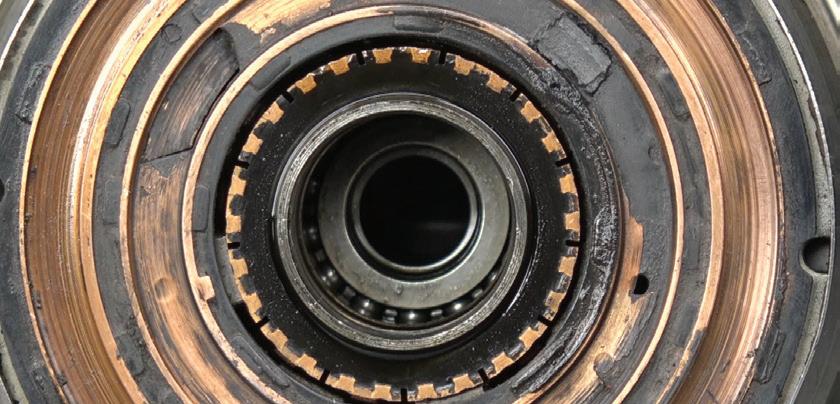
A stator winding removed from a 3-phase motor. (all photos courtesy ACDC)
FIND. ORDER. DELIVERED. YOUR TIME MATTERS LESS TIME CLICKING. MORE TIME FOR FIXING. MYPLACE4PARTS is the easiest, fastest parts ordering platform for professional technicians. www.myplace4parts.com
volts. (I will use the term DVOM, not DMM.) The voltage levels of some electric vehicles are 800 volts. Many older CAT III-rated meters were limited to 600 volts. Around the year 2000, CAT III 1,000-volt meters were offered. In M/Y 2004, Toyota added a boost converter to their Prius that raised the voltage to 500 volts. Safely controlling voltages much higher than 900 volts is a safety concern for most OEMs.

When using a DVOM, make sure your meter is rated for the work environment you are in. Many shops have moved all the CAT III 1000-volt meters, scopes and other equipment to a new tool box that is clearly marked “CAT III 1,000 volts only.” Some have gone as far as to replace every old piece of tooling or equipment with a CAT III 1,000-volt-rated unit. No matter what you do, be safe and do not take unnecessary chances.

USING THE METER ON AN HV CIRCUIT
The meter ratings (CAT II, III, IV, etc.) are based on the spacing between the components inside the case and the possibility of an explosion. The meter screen is the weakest part of the meter and the most likely to become a projectile if the meter is hit with more voltage
and current than it can safely read. It takes about the same amount of time to do something right as it does to do it wrong. “Safe down” procedures want you to confirm that the HV battery has been disconnected from the rest of the system and the HV capacitors have been discharged as they are designed to do. Your equipment, and its proper use and care, is a personal safety issue.
MILLIOHM METER
When induction motors were introduced (thank you GM and Tesla), a milliohm meter became a vital piece of equipment. The choice of a scope or a meter is dependent on the voltage signal you are measuring. If the voltage varies, use a scope. What if there is no voltage? Induction motors do not produce voltage when the rotor is spun manually while disconnected from the inverter. Therefore, a precise measurement of the stator windings in an induction motor must be made with a milliohm meter when the electric motor is being tested. You may be wondering why your DVOM’s ohm reading is not up to the job. When you use a DVOM and a milliohm meter it will become obvious. Any resistance that is over one ohm will accurately report that resistance to your DVOM. When the ohm specification is under one ohm, then your meter is not useful as it will not measure correctly under one ohm. The reading will be off, so a milliohm meter must be used. Toyota has a specification of 0.016 ohm for the stator windings in some motors.
INSULATION TESTER
This type of tester will produce 50 to 1,000 DC volts to test the insulation of the HV cables and some high voltage circuits. The current produced is milli-amps for safety reasons. The manuals are easy to understand but the difficulty is knowing where to connect the leads. Understanding the “construction and function” of all the parts that make up an EMV is required so you know where to test. Make sure you carefully examine the cross section of high voltage cables. If you have access to spare high voltage orange cables, cut them in half and then use a belt sander to make it easier to see the layers of the cables. Note the shielding and when and where it is used. Note the grounding of the shielding both in external cables and those used inside HV components. When using an “insulation tester” be sure the capacitors have been discharged and the HV battery pack is off. Safety is always number one.
18 ASP | AUGUST 2023 EV SERVICE TIPS
A DVOM that is CAT III rated to 1,000 volts is required.
A CAT III meter with a ghost voltage adapter plugged in.
Fluke makes the only adapter we know of for eliminating ghost voltage. Milliohm meter used for testing stator windings.


AUGUST 2023 | ASP 19
Smart Logic Diagnostics™ (IR, CCA Test, True Reserve Capacity, Automatic Load Test and Charge Acceptance) ECU ECU RE-FLASH 100Amps (CCCV) (Constant Current Constant Voltage) ARGOS Cloud Based System Thermal IR Scanner and Embedded Database Advanced and Accurate Leak Tester Embedded Database (Parameters & Thresholds) Designed for Repair Shop Environment Safety Threshold Protection (Housing/Cooling System) Intuitive 7” LED Touch Screen (User friendly Icons) ARGOS Cloud Based System Automatic Updates via Wi-Fi CHARGER/DISCHARGER lllllllllllllllllllllllllllllllllllllllll EV BATTERY PACK CHARGER/MAINTAINER lllllllllllllllllllllllllllllllllllllllll BATTERY ANALYZER e-xteq.com - marketingusa@e-xteq.com - support.usa@e-xteq - 1-877-453-3265 Battery Pack Housing / Cooling System Electric Motor Cavity Gearbox Housing / Cooling System 2308ASP_EXTEQ.indd 1 7/14/23 1:45 PM
STRAY OR GHOST VOLTAGE ELIMINATORS
A high impedance meter presents virtually no load to the circuit under test. By design, this is the ideal situation, since you don’t want to have the meter loading the circuit and affecting the circuit measurements. Ghost voltage reading may be as high as 50% of the energized voltage in the same proximity. Is this voltage real? Yes, it is, but it’s static voltage, containing no real energy or current flow. For the tech who needs to determine whether a circuit or connection is energized or not, this stray voltage reading presents a real source of confusion. Is the connection hot or not?
THE FLUKE SV225 STRAY VOLTAGE ADAPTER


The articles I have written are brand neutral. In this case the only product on the market I have ever found that works with a DVOM (and I have looked hard) is made by Fluke. The stray voltage adapter is a DVOM accessory part that allows the DVOM to measure circuits subject to stray or ghost voltages from adjacent energized wiring. The adapter provides a low impedance load to the measured circuit that desensitizes the meter to low energy sources of interference. It allows a high impedance DVOM to make an accurate determination as to whether the circuit under test is energized or not. Using this adapter allows the tech to determine whether a circuit, connection, cable or connector is energized. If the measurement points are energized with a “hard” voltage, the meter will simply display the voltage reading. If the measurement points contain a stray or ghost voltage, the meter will read very close to zero volts indicating the circuit or connection is deenergized.
SUMMARY
The news continues to favor EVs over internal combustion. In 1999 I started my training into high voltage safety after I bought a Honda Insight hybrid. It has been a journey that I have taken with thousands of others who were involved in this transition. I have had the good fortune of working closely with those who engineered, built and ultimately fixed the EMVs that presented concerns to the owners. As a shop owner/technician/journalist/ technician trainer, it has been amazing to see this technology grow. The road has had its share of potholes, danger signs and detours, but we are still moving forward and at a much faster rate of speed. The future awaits us but the EMVs are here now, so get ready. This technology is not going away.

20 ASP | AUGUST 2023 EV SERVICE TIPS
Craig Van Batenburg is the lead trainer and CEO of ACDC, a hybrid and plug-in technician training company based in Worcester, Mass. ACDC started hybrid training in early 2000. ACDC owns a fleet of 18 EMVs, from the most popular models to current EVs. Recently, ACDC has expanded to 5,000 square feet and added a battery lab. Class info is available at www.FixHybrid.com or call 508 826 4546. Contact Craig at Craig@fixhybrid.com.
Induction motor introduced by GM in model year 2012.
Insulation tester in an ACDC class.
Variable Valve Timing

The technology has been around for centuries, but it’s still changing
 BY JEFF TAYLOR
VARIABLE VALVE TIMING OR VVT ISbeing used on most engines today, and for good reason. It provides the engine with the best camshaft timing under a myriad of operating conditions. On the non-VVT engine, the camshaft timing in relation to the crankshaft is fixed, forcing the engineers to often compromise on camshaft design. Most drivers expect a smooth idle quality and good engine performance, but the manufacturer is looking for fuel economy and low emissions, hence the need to compromise.
Using VVT allows the engineers to enhance the power output of the engine, and to improve torque delivery across the entire operational rpm range. The introduction to VVT to the internal combustion engine allowed engineers to use a given camshaft on an engine and get the best of both worlds.


The VVT that we are most familiar with is the Continuous Camshaft Phasing VVT. It will continuously advance or retard direction of the camshaft’s base timing location in relation to the crankshaft. The most generic form of VVT varies the camshaft timing using a single hydraulic camshaft phaser on each camshaft. It is a simple, basic and less expensive way to produce the system. Nonetheless this system has limitations. It cannot vary the camshafts’ valve opening duration or change the amount of valve lift. But the biggest limitation to this system is that it will not function when the engine is cold or when there is low oil pressure.

The most common VVT system uses the engine’s pressurized oil system to hydraulically activate the VVT camshaft phasers. Because the VVT system depends on the engine’s oil for functionality, any concerns in the engine’s oil system will adversely affect the VVT system. Low oil pressure, low oil level, incorrect oil viscosity, over-extended service intervals and many other oil-related concerns can and do affect the abil-


ity of the VVT system to function properly. We have all heard of, read about or personally experienced a VVT issue that was completely preventable with just simple maintenance. Many techs have dealt with MIL complaints, drivability concerns and engine noises only to find that the engine oil is low. The simple act of inspecting and keeping the correct engine oil level can dramatically reduce many issues to which the VVT system is susceptible. The importance of the correct engine oil being installed and changed at the correct and regular intervals has a profound effect on the durability and longevity of the VVT system and its components.
But that doesn’t mean that the most well cared for engine can’t experience a VVT issue. The first generation of the Ford EcoBoost engines quickly comes to mind. The first V6 EcoBoost engine design was a known VVT nightmare for many owners. There are too many TSBs to even talk about on this engine, but the root cause of all the issues is rumored to be that Ford rushed this engine to market. They needed a powerful, fuel efficient small displacement engine to replace the V8 engine. The later generations of the EcoBoost engines have made drastic improvements to the engine’s VVT
22 ASP | AUGUST 2023
VARIABLE VALVE TIMING
The oil-based VVT system uses the engine’s oil system to move the camshaft phasers, and poor or sporadic maintenance is a common cause of VVT issues. (all photos by author)


AUGUST 2023 | ASP 23 © 2023 Wrenchers LLC. All Rights Reserved. CHILL FEEL THE HI L Space-saving and energy-efficient Cool Boss evaporative air coolers are made for quiet operation and portability, allowing you to use them indoors or outdoors. Just hook up to a standard garden hose or fill the portable water tank, turn it on, and start chilling. It’s just that simple! Learn more at COOLBOSS.COM or call 1-855-2BE-COOL. A Division of BendPak Inc. ©2023 CoolBossTM. A division of BendPak Inc. All rights reserved. BendPak® is a registered trademark.*Your specific location may require a combination of multiple models and/or sizes to provide the most effective cooling experience. Control Your Climate. Just Add Water.™ FEATURES Auto-refill 26˚F Cooling* Large Cooling Area Easy-to-use Control Panel LEARN MORE ALL-IN-1 SHOPPING REV UP YOUR SAVINGS! ! 1-800-261-7729 Ask about our price promise guarantee. Call Now for a FREE catalog! Equipment | Tools | Shop Essentials WE WILL NOT BE UNDERSOLD!


24 ASP | AUGUST 2023 All your digital O’Reilly and vendor catalogs in one easy-to-use location! Visit FirstCallOnline.com and click on the e-Publications link today! Product linking now available. WWW.FIRSTCALLONLINE.COM first call® online E-publications Look for this icon 2308ASP_OReillyAutoParts_3rdpg.indd 1 7/11/23 3:12 PM VARIABLE VALVE TIMING The Ford EcoBoost quickly comes to mind when we mention the failure or issues of a VVT system. The main timing chain on this 2016 F150 was elongated badly. You can see the difference in timing chain length when comparing new vs. old in this photo.


AUGUST 2023 | ASP 25ADV-1865 FIRSTCALLONLINE.COM Visit our website for a complete, internet-based catalog designed exclusively for the Professional. FILTRATION MicroGard® supplies a wide variety of filters for most popular late model passenger cars and light trucks. • Oil Filters • Air Filters • Fuel Filters • Cabin Air Filters • PCV Valves MAKING IT FASTER AND EASIER THAN EVER TO ORDER PARTS Let Us Be Your Parts & Equipment Supplier AIR, OIL, FUEL & CABIN FILTERS FROM MICROGARD ® A COMPLETE LINE OF AVAILABLE EXCLUSIVELY AT TION Scan here with your phone’s camera to view catalog! WWW.FIRSTCALLONLINECATALOGS.COM
system design and components, while still utilizing the oil-based VVT system.
GM, BMW, Mini, Honda and other manufacturers had issues with the extended services they were promoting. The Gasoline Direct Injection (GDI) on some of these engines created a sharp grainy carbon-like material in the combustion chambers, which found its way into the engine oil and accelerated the wear of the timing chains and components. Accelerated timing chain wear caused the chains to elongate (they don’t stretch) causing many concerns. GM changed the construction of their timing components, reformulated the engine oil used, and also reduced the mileage for the oil life monitor (OLM) with a reflash.
The fact is still that most of the oil-based VVT troubles have come down to insufficient maintenance, and knowing this, some manufacturers are moving to an electric camshaft phaser to perform the VVT function. This resolves several issues and limitations that the oil-based VVT system suffers from. By using an electric DC motor to control the camshaft’s phase position, the electric system is functional in a wider range of operating conditions.
The electric VVT is fully functional when the engine is cold or at low engine rpm (low oil pressure), and has an almost instant response for precise camshaft phase location, larger operational range (more degrees of change) and it is not dependent on engine oil pressure for operation. These electric VVT advantages have lead Mazda, Toyota, Nissan and Hyundai/Kia to incorporate this technology into their engine designs. Currently the trend of the major manufacturers is to use the electric VVT on the intake camshafts and the familiar oil-based VVT system on the exhaust camshafts.
So how does the electric VVT system work? There are different variations, but the system is closely related to the oil-based VVT system. Instead of a hydraulic phaser on the end of the camshaft, there will be an electric DC motor phaser assembly. The electric VVT system will be controlled and monitored by the PCM and will use either internal location sensors for feedback on some engines using existing camshaft sensors to report the camshafts’ phase position.
When the system is in operation the electric VVT motor will be spinning either at the same speed, spinning faster or spinning slower than the camshaft it is attached to. The electric VVT motor will be attached to a mechanical assembly that will adjust the phase of the camshaft. Toyota uses a lever mechanism and cycloidal reductor; others use a variation of a planetary gear set to send the electric VVT motor’s movement to the camshaft it is attached to. The electric VVT motor making the camshaft phase position change can be found internally behind the timing cover on the camshaft, or externally outside the timing cover. Toyota and Mazda chose to install the electrical VVT motor components externally. Hyundai/Kia installed their electric VVT motor internally.
When the electric VVT motor and camshaft that it is attached to are spinning at the same speed, the base cam/crank relationship is kept. This is the HOLD position. When the electric VVT motor spins slightly faster, the cam/crank relationship will


26 ASP | AUGUST 2023 VARIABLE VALVE TIMING
This is the inside of the brush cover on a 2017 Hyundai Sonata. The E-CVVT brushes are worn out and causing a high idle, hesitation and the MIL was on.
This is the entire E-CVVT assembly on the 2017 Hyundai Sonata. You can see the cover and the internally located E-CVVT motor assembly.
change, and the camshaft will now be advanced. When the electric VVT motor spins slightly slower, the intake camshaft will be retarded. The movement of the phaser is not much, in the range of 40 degrees of crankshaft rotation angle.
Hyundai/Kia engines have been experiencing more than their share of concerns with their electric VVT system. Yes, other manufacturers are having some sporadic issues, but not quite as many as Hyundai/Kia has had. The decision to install the electric VVT motor internally may be the cause.
Hyundai/Kia has been using the E-CVVT (Electric-Continuous Variable Valve Timing) system since 2015 and it uses a set of brushes in a protective cover to send the needed current to run and control the ECVVT motor assembly. The system is to be sealed from the internal parts of the engine, but the bolt used to attach the E-CVVT assembly to the intake camshaft is exposed to the oil pressure that is inside the hollow intake camshaft. (The camshaft supplies pressurized oil to lubricate the camshaft journals.) This attaching bolt has a seal that is meant to stop the oil from entering the ECVVT brush cover, but it has a nasty habit of blowing out, filling the brush cover with engine oil. The oil inside the brush cover causes the system to fail and the most common code DTC set is the P0010:00 — In-

take camshaft position (CMP) A actuator circuit (bank 1). When this DTC is set, the vehicle will often hesitate and experience a higher fixed idle of 1,200 rpm when in park or neutral.
There have been multiple TSBs issued about this concern, and the repair is not that difficult to perform if the leaking oil has not ruined the contact assembly of the E-CVVT. There are some special tools needed and

AUGUST 2023 | ASP 27 A global OE brake system supplier. ATE - A brand of Continental. Find the application you need at: ATE-NA.com ATE brake pad friction materials are precisely formulated to match the OE pad’s specifications. This makes braking performance the same as when the vehicle left the dealership. And that’s why we have over 150 brake pad formulations. Why 150 different brake pad formulations? 2308ASP_ContinentalCorp.indd 1 5/31/23 3:20 PM
This is the front contact area of the E-CVVT motor assembly. The seal that blows out would cover the area in the middle of the assembly, after the bolt that secures this assembly to the intake camshaft is installed. You can clearly see the wear on this E-CVVT assembly.
particular attention to the seal’s location in the end of the E-CVVT assembly is key. If the E-CVVT assembly has experienced damage, the timing cover will have to be removed and the E-CVVT assembly replaced. This procedure will involve the removal of the timing chain and after the repair is completed, a scan tool is needed to reset the learned E-CVVT values. There have been some issues with E-CVVT brushes wearing out and setting DTCs. It is important to remember that there are two sets of brushes in the E-CVVT assembly. One set is in the brush cover, which has a wear specification and is straightforward to service. Another set is in the E-CVVT assembly itself, and if these go bad you are removing the timing chain to replace the entire E-CVVT assembly.


Development of the VVT system has continued and the use of an electric VVT phaser has been taken to a new level of camshaft control by Hyundai/Kia with their latest VVT design. The Continuously Variable Valve Duration (CVVD) system developed by Hyundai/ Kia is a complex electrically driven system that is applied to the intake camshaft only. This CVVD technology cuts engine emissions by 12%, boosts performance by 4% and supplies a 5% improvement in fuel efficiency.
The CVVD combines three distinct types of variable valve operation on an engine:
The CVVD system can function as a VVT system continuously changing the intake’s camshaft phasing.
The CVVD system can function as a Variable Valve Lift (VVL) system adjusting the amount of lift that the
intake valves will have, controlling the amount of air entering each cylinder.
The CVVD system can function as a Continuously Variable Valve Duration (CVVD) system adjusting how long the intake valves are kept open.
The CVVD valve control technology controls the duration of valve opening and closing according to driving conditions. The system supplies the optimal open and closing times of the intake valves, enhancing both engine performance and fuel efficiency. Hyundai is the first to use this type of CVVD technology in a production engine. The exhaust camshaft of the CVVD-equipped engine still uses the familiar engine-oil-based phasing system, controlling only the exhaust valve opening and closing timing. (Plans are to incorporate the CVVD system on the exhaust camshaft in the future.)
The first VVT system was designed for use on steam engines in the 1830s, and that technology was transferred to the automotive industry early in the 1900s. The use of VVT is essential on today’s internal combustion engines. Today’s VVT systems optimize engine performance, providing a smooth idle, higher torque values at low engine rpm and better fuel economy. The system has had its issues, but as with most things, the engineers will work hard to solve the issues that either they created, or we the owners and drivers have created.
28 ASP | AUGUST 2023 VARIABLE VALVE TIMING
Jeff Taylor boasts a 30-plus year career in the automotive industry as a fully licensed professional lead technician. Jeff works for the CARS Training Network Inc. in Oshawa, Ontario, Canada. He is also heavily involved in government focus groups, serves as an accomplished technical writer and he has completed in international diagnostic competitions as well as providing his expertise as an automotive technical instructor for a major aftermarket parts retailer.
The arrow is pointing to the VVT assembly on this 2023 Toyota Rav4 2.5 Dynamic Force engine. Toyota designed their electric VVT motor to be externally located.
This is a cross-section of the E-CVVT oil sealing plug and how the seal is meant to be reinstalled.
Separation prevention groove
C-ring Motor Shaft
meets


business education. Where professionals and industry leaders from around the world gather to make connections, catch the latest demos, and find the perfect products. And it’s where you belong. Secure your spot today.


AUGUST 2023 | ASP 29
the automotive aftermarket community
It’s
REGISTRATION IS NOW OPEN. | AAPEXSHOW.COM OCTOBER 31–NOVEMBER 2 LAS VEGAS, NV | THE VENETIAN EXPO | #AAPEX23 WHERE SERVICE MEETS SUPPLY CHAIN
Nothing brings
together like AAPEX.
the only event where hands-on training
expert-led
Addressing No-Start Issues


Tips and tools for modern vehicles


 BY BILL FULTON
WE ARE ALL FACED WITH NO-START issues from time to time. Some are basic and fundamental in nature while others on some late model vehicles can be somewhat complex. We will begin this article covering a no-crank or no-start condition. Most late model vehicles are equipped with a theft deterrent system. The challenge is determining which systems lock out the starter. For example, the early GM Pass Lock systems did not lock out the starter. The PCM would disable the injectors within two seconds of a startup. These systems were a favorite of car thieves who traveled in pairs. While one thief entered the car and knocked out the ignition switch the other thief was under the hood with a can of carburetor spray cleaner. As soon as thief No. 1 got the engine cranking thief No. 2 shot carb cleaner into the intake and the engine exceeded 200 rpm. At that point the BCM (the dominant Pass Lock Module) saw the engine above 200 rpm and assumed the fault occurred after a successful start and simply set a DTC for a Pass Lock failure — and the thieves drove off with the vehicle.
Because of this the GM Pass Key 1 and Pass Key 2 systems and some other theft-deterrent systems will lock out the starter. Aside from the mechanical cut of the Pass Lock key, there are no electronics inside a Pass Lock key. On the GM Pass Key 1 system the ignition key has a resistor embedded in the key. The resistor element pulls a voltage value low. When this voltage value is recognized by the theft-deterrent module a signal is sent to the PCM which allows the PCM to ground side control the starter enable relay while the PCM allows for injector operation. The resistive elements embedded in the key are known to wear down which creates an opening. When this occurs a no crank condition will exist. Whenever faced with a theft-deterrent issue it is always best to request both keys from the car owner. This rule should apply to all vehicle systems except the GM Pass Lock systems. Also keep in mind that some key transponders contain a battery that may be depleted.

30 ASP | AUGUST 2023
ADDRESSING NO-START ISSUES
Fig. 1: Battery ground connected to body ground.
Fig. 2: Schematic from a late model Cadillac that experienced a no-crank condition. No. 1 DVOM shows good dynamic voltage from the ignition switch in crank mode. Meter reading 2 went to .4 volts. Readings 3 and 4 both show good dynamic voltage. What you are not seeing is the voltage drop from placing the positive meter lead to the block and negative meter lead back to battery negative which indicated nearly full voltage from a bad negative ground cable from block to body ground.


AUGUST 2023 | ASP 31
AutoZone, Inc. All rights reserved. AutoZone, AutoZone & Design, and Duralast
of AutoZone IP LLC or one of its affiliates. All other
are the property of their respective owners. All photographic, clerical, typographical and other errors are subject to correction.
bundle and noise free guarantee requires the purchase of any set of Duralast, Duralast Gold, Duralast Elite pads, 2 Duralast or Duralast Gold rotors and hardware (when available) on the same invoice. Guarantee covers parts and labor for 90 days when professionally installed. SEE THE DIFFERENCE TODAY REPAIR WITH DURALAST. REPAIR WITH CONFIDENCE. SLOTS AND CHAMFERS OE STYLE SHIMS OE FRICTION FORMULATIONS OE SHOP EXCLUSIVE BRAKE BUNDLE* PRICING ON AUTOZONEPRO.COM/BRAKES
©2023
are registered marks
marks
*Brake
We begin with a voltage test of the vehicle’s battery. Most technicians know that the battery is buried underneath the back seat on some vehicles. Notice in Fig.1 the battery ground is connected to body ground.
Let’s take a look at a starter system schematic from a late model Cadillac which experienced a no-crank condition in Fig. 2. The number 1 DVOM in Fig. 2 showed good dynamic voltage from the ignition switch in the crank mode. Meter reading 2 went to 0.4 volts indicating the PCM was ground side controlling the pull in the windings of the starter enable relay. Now we look for good dynamic voltage from the power side of the starter enable relay in DVOM No. 3 which also indicated good dynamic voltage. Now to meter reading 4 which is the main positive feed cable to the starter which also showed good dynamic voltage. What you are not seeing here is the voltage drop from placing the positive meter lead to the block and the negative meter lead back to
the battery negative terminal which indicated nearly full voltage from a bad negative ground cable from the block to body ground. Fig. 3 shows the bad ground cable. We were curious as to why we had a laundry list of U series codes from all modules on the class 2 circuit including the theft deterrent module. So we scoped out the class 2 signal at the DLC. In Fig. 4 note that the class 2 signal shifted well above ground when we went to the cranking mode. This initially told us that a bad ground existed. The block to body ground cable was replaced.
A late model Oldsmobile vehicle came in with a very intermittent stall and no crank conditions. After several test drives we finally got the car to stall. In Fig. 5 we probed the main feed pink wire coming from the ignition switch and with our meter in the Min/Max mode we caught the loss of voltage from a bad ignition switch.
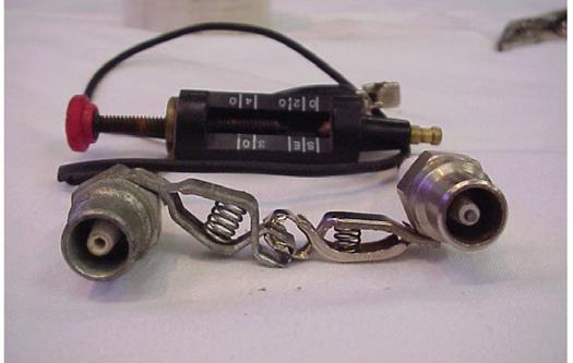
Most technicians when faced with a no start will check for spark with a spark tester. When doing so it is important to know the KV value of different spark testers. Note Fig. 6. The spark tester on the right is known as a ST 115 meaning that it requires a 15KV to bridge the gap. This tester is used on the conventional breaker point ignition system. The ST125 shown on the left is used on the modern day high energy systems such as H.E.I. and COP systems. The adjustable spark tester in the rear of Fig. 6 can be adjusted to apply to all systems. A three-quarter-inch air gap will require about 30 KV.
I want to share a case study with you that illustrates the importance of knowing which spark tester to use. A high mileage 4.3L S-10 came in with a complaint of a good crank and a no-start condition. Using the ST125 at the coil wire showed a good consistent spark. Using the ST125 at the end of a plug wire indicated no spark. The vehicle has all new secondary components. We then decided to use the ST 115 at the end of a plug wire which also indicated no spark. What could be the problem? We determined that a bad timing chain had created a bad alignment between the tip of the rotor and the distributor cap causing a loss of voltage inside the distributor cap.

I want to share with you one of my favorite tests in conducting the WOT cranking KV test. We are using the bar graph mode in Fig. 7 which is essentially the firing line. Notice the 29 to 30 KV values. This test does confirm three essential points — one being the ability of the ignition system to deliver 30KV. Second, it also stresses the insulation of the secondary circuit, and

32 ASP | AUGUST 2023
ADDRESSING NO-START ISSUES
Fig. 4: The class 2 signal shifted well above ground when we went to the cranking mode. This initially told us that a bad ground existed.
Fig. 3: Example of a bad ground cable.
CAT IV MULTIMETER


AUTOMOTIVE & HYBRID
Handheld professional multimeter that can measure up to 1,000V AC/DC voltage and 10A AC/DC current


Measure resistance, diode, continuity, and mx-Pulse/duty cycle


Features auto ranging, data hold, and is CAT III 1000V and CAT IV 600V rated


Includes test leads, batteries, and a temperature probe


DOES YOUR METER MEASURE UP?
#13811
#


WWW.LANGTOOLS.COM
2308ASP_A&EHandTools.indd 1 7/12/23 10:45 AM
Fig. 5: Probing the main pink feed wire from the ignition switch.
Fig. 6: The spark tester on the right is known as a ST 115, requiring a 15KV to bridge the gap. The ST 125 on the left is used on modern high energy systems such as H.E.I. and COP systems.


34 ASP | AUGUST 2023
Fig. 10: Chevy Express no start and loss of secondary.
ADDRESSING NO-START ISSUES
Fig. 11: Chevy Express schematic.
Fig. 7: Conducting a WOT cranking KV test, using the bar graph mode, which is essentially the firing line. Notice the 29 to 30 KV values.
Fig. 8: COP wands can be used on plug wires and COP units to check for a secondary event.
Fig. 9: Example of secondary event. Notice the 10 KV firing line and the 2 milli-second spark duration.
third, it verifies good compression values. COP wands are indicated in Fig. 8. These wands can be used on plug wires and COP units to check for a secondary event such as what is shown in Fig. 9. Notice the 10KV firing line and the two millisecond spark duration.


A Chevy Express van came in with an intermittent stall and no start with a crank sensor code. The crank sensor has been replaced twice as shown in Fig. 10. Looking at the schematic in Fig. 11 we tapped into the CKP circuit. Look at the waveform in Fig. 12. You can see the


AUGUST 2023 | ASP 35 Craig@fixhybrid.com www.fixhybrid.com (508)-826-4546 Tesla Training Hands On Training 3 Day Classes, Online Webinars, 8 Hour On The Road Classes ACDC is your ONE-STOP resource for Hybrid and Electric Vehicle Training needs! ACDC offers: • Hands On Tesla Classes • HEV-EV Classes
Webinars - Live and Recorded • Books
Safety Equipment 2304ASP_VanBatenburgsGarage.indd 1 3/20/23 9:12 AM
•
•
Fig. 12: Notice the waveform showing a signal drop out.
Fig. 13: A low inductive amp probe is essential, especially for coils that are difficult to access.
Fig. 14: Using a low inductive amp probe and clamping around the B+ feed wire, an amperage waveform will verify proper coil saturation.
Fig. 15: The fuel pump fuse was removed and we jumpered across the jumper lead with our amp probe.
signal drop out. Fig. 13 indicates a must have tool with a low inductive amp probe. We know that there are several engines where the coils are buried under the valve cover making it very difficult to check for spark. Using the low inductive amp probe and clamping the probe around the B+ feed wire an amperage waveform will verify that we have proper coil saturation as in Fig. 14.


Low inductive current probes are very valuable in checking for mechanical, electrical and fuel pressure.
Notice Fig. 15 where we simply removed the fuel pump fuse and jumpered across the jumper lead with our amp probe. Fig. 16 and Fig. 17 verify the importance of mastering the low inductive amp probe.
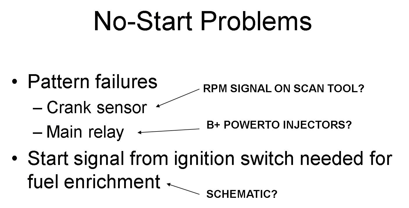
Fig. 18 specifically addresses some common failures on the Hyundai and Kia systems where the PCM needs to see a crank start up to give the injectors more
enrichment during start up. In addition the main relays are known to fail causing a no start. Fig. 19 shows the schematic. Fig. 20 shows the main relay schematic. Notice the main relay powers up the PCM and the injectors. A very intermittent no start came in on a Kia. A scope was set up to monitor the main relay in and power out as well as the B+ to the fuel pump. Fig. 21 shows the failure.

Notice power into the main relay is there but no power out. You can also see that there is no B+ to the
36 ASP | AUGUST 2023
Fig. 16: Looking at fuel pump signatures, the importance of mastering the low inductive amp probe is clear.
Fig. 17: This fuel pump startup current draw again shows the importance of mastering the low inductive amp probe.
Fig. 18: Some common failures on Hyundai and Kia systems where the PCM needs to see a crank start up. In addition, many relays are known to fail, causing a no start.
ADDRESSING NO-START ISSUES
Fig. 19: Schematic example where the PCM needs to see crank start up to provide injectors more enrichment.
fuel pump. Fig. 22 shows good voltage out of the main relay and B+ to the fuel pump.


Checking for injector pulses on GDI engines will require a DSO. Fig. 23 shows the voltage trace and the current flow values on a GDI engine. If checking for a voltage trace you must use two channels of the DSO. When using a current probe we simply clamp around one injector wire.

Back in the old days a spark tester and a can of carb spray cleaner was all that was needed to check for loss of spark or fuel pressure. On today’s modern engines the amp probe becomes a tool of necessity.
The industry is better because of your commitment.
Bill Fulton is the author of Mitchell 1’s Advanced Engine Performance Diagnostics and Advanced Engine Diagnostics manuals. He is also the author of several lab scope and drivability manuals such as Ford, Toyota, GM and Chrysler OBD I and OBD II systems, fuel system testing, many other training manuals in addition to his own 101 Lab Scope Testing Tips. He is a certified Master Technician with more than 30 years of training and R&D experience. He was rated as a Top Technical Trainer and has instructed for Mitchell 1, Precision Tune, OTC, O’Reilly Auto Parts, BWD, JD Byrider, Snap-on Vetronix and Standard Ignition programs. You may have also seen Fulton in many Lightning Bolt Training videos and DVDs and read his articles in many auto service magazines. He currently owns and operates Ohio Automotive Technology, which is an automotive repair and research
AUGUST 2023 | ASP 37
development center.
Fig. 21: Example of a Kia intermittent no start. A scope was set up to monitor the main relay in and power out as well as the B+ to the fuel pump. Notice power in to the main relay but no power out. You can also see that there is no B+ to the fuel pump.
Fig. 22: Example of good voltage out of the main relay and B+ to the fuel pump.
Fig. 23: Example of voltage trace and current flow values on a GDI engine.
Fig. 20: Main relay schematic. Notice that the main relay powers up the PCM and the injectors.
PRO DUCTS
Axone Voice offers hands-free help
•••
TEXA USA has unveiled Axone Voice, a single, portable diagnostic device that provides hands-free help to technicians. The IDC5 software has new features for interaction, authentication and usability. The Axone Voice is equipped with a 13.3-inch screen protected by Gorilla Glass. The Windows 10 Enterprise operating system is powered by an Intel Core i5 processor with 16 GB RAM and 512 GB storage. Technicians can say “Hey TEXA” ahead of any command. After the selection or vehicle scan, Axone Voice suggests services available. It has cameras with facial recognition capabilities to identify users and unlock exclusive functions and access diagnostic authentication procedures required by manufacturers.
TEXA USA texausa.com
Photo courtesy: TEXA USA

Blue Streak coils made to endure
•••
Blue Streak heavier-duty ignition coil kits from Standard are designed to last. The Blue Streak engineering team studies OE coil failures and then designs its Blue Streak heavierduty coils to correct those issues for improved performance and a longer service life. These improvements can include additional bobbins, which allow the coil to run cooler, or improved seals to prevent moisture intrusion. Popular ignition coils are also available in prepackaged kits, which include a matched set of Blue Streak heavier-duty ignition coils. Kits are available for both import and domestic cars, trucks and SUVs.

Standard Motor Products standardbrand.com
Photo courtesy: SMP
Ceramic ADVICS brake pads extend life

•••
Premium brake pads from ADVICS Aftermarket North America Inc. are developed from ceramic friction technology which produces a smooth and quiet stopping experience. The technology also improves pad and rotor life. The brake pads feature proprietary vehicle-specific formulations for optimum performance and heat dissipation with steel backing plates and advanced slots and chamfers to reduce noise, absorb vibration and provide better cost-per-mile value.
ADVICS Aftermarket North America advicsaftermarket.com
Photo courtesy: ADVICS
BendPak double lifts offer flexibility
•••
BendPak Inc. has unveiled the BendPak PL -12000DP and PL12000DPS double-wide parking lifts that accommodate four vehicles in two parking spots. The lifts operate independently from one another, so one can be lowered while the other remains still and the structure provides double-car-width open front access. The PL-12000DP tall-rise, extended-length model offers a maximum rise of 82.2 inches, 183-inch runways, and a drive-through height of 80.5 inches. The PL-12000DPS standard-rise, standard-length lift has a more compact footprint to fit in smaller spaces. Its max rise is 70.2 inches, with 159-inch runways and a drivethrough height of 68.5 inches. Both models have a total rated capacity of 12,000 pounds, or 6,000 pounds per platform.

BendPak bendpak.com
Photo courtesy: BendPak
38 ASP | AUGUST 2023
Continental wiper blades resist UV rays

•••
Continental ClearContact Premium Beam wiper blades are composed of rubber that resists UV light and environmental conditions to remain flexible, and also offer a longer life. The synthetic rubber formula performs in all weather, even at high speeds and in extreme temperatures. The blades are tested to perform over 1.5 million cycles. The wiper blades feature a dual-point coupler design that provides uniform contact with the windshield to help eliminate streaking. They are designed to be Year/Make/ Model specific, so no adapters are needed. Front wiper coverage includes 14-part numbers with sizes from 15 to 28 inches, while rear wiper coverage consists of 19-part numbers available in 10-to-16-inch sizes.
Continental Automotive Technologies
continental-aftermarket.com
Photo courtesy: Continental
Micron SuperStar filter has four stages
•••
Walmec North America has introduced its .01 Micron SuperStar filter to provide clean, dry and compressed air resulting in the removal of any vapors and contaminants down to .01 micron. The four-stage filtration system has a .01 micron rating, with flow ranges of 50 SCFM, 75 SCFM or 100 SCFM, and can handle pressure ratings of up to 250 PSI. The first and secondstage filters remove moisture, liquids, dust, rust, scale and other contaminants to five microns. An automatic float drain under the second stage filter expels liquids whenever an ounce or more is present. The third and fourth stages remove any remaining particles and absorb any remaining vapors.

Walmec North America
walmecna.com
Photo courtesy: Walmec
Autel XLink connects and programs

•••
Autel U.S. has released its MaxiFLASH XLink, a three-inone programming, communication and remote touchscreen device. The XLink is a 6.5-inch standalone tool that can connect to experienced programmers and diagnostics with OE software subscriptions and tools to complete needed tasks. The XLink enables technicians via the Remote Expert platform to obtain expert help and access OE data remotely. A J2534 pass-through programming capability allows techs to flash modules with a Windows pc and OE subscriptions onsite, and an enhanced VCI that supports the latest communication protocols and is compatible with all Autel MaxiSYS tablets.
Autel U.S.
autel.com
Photo courtesy: Autel
Schaeffler adds INA belt tensioner
•••
Schaeffler Group USA, Inc. expanded its range of front-end auxiliary drive (FEAD) with a new belt tensioner under in the INA brand product line. As a hydraulic dampened tensioner, the FT0800 can be used to lower the pre-tension to a minimum while still controlling FEAD performance. The company’s REPXPERT service brand provides technical information, training, product catalogs and repair support for all INA products, plus chassis and transmission products. With the addition of FT0800, Schaeffler provides belt tensioner coverage for the latest Honda Accord, Civic and CR-V models and provides belt tensioner coverage for Honda L15BE, L15B7 and L15BY engines.

Schaeffler Group USA Inc.
schaeffler.us
Photo courtesy: Schaeffler
AUGUST 2023 | ASP 39
New and innovative equipment for your tool chest and shop
BULLETINS
BMW HESITATION FIX
This bulletin applies to 2017 BMW 330i vehicles equipped with a 2.0L engine, as well as 2 Series, 3 Series, 4 Series, 5 Series, 6 Series and 7 Series vehicles. The vehicle may run rough or hesitate when accelerating from a stop, and DTC FC 21A02D (combustion control: valve lift correction when at idle) may be stored in the DME fault memory. This may be due to a software error in the DME (digital motor electronics). Update the vehicle software using ISTA 4.27.10 or higher.

age difference between APP sensor 1 and APP sensor 2 that exceeds a predetermined value for more than a calibrated period of time, setting P2138. Note that aftermarket equipment can generate this DTC. Verify that no aftermarket equipment is connected to any of the APP sensor signal or low reference circuits or to any other ECM/PCM 5V reference circuits. Perform a diagnostic system check. If any 5V reference DTCs are set, refer to the DTC list. If any 5V reference DTCs are not set, locate the IP (instrument panel) body harness connector. Inspect for a water leak in that area. If necessary, use a water hose to determine the source of the leak. If a leak is found, repair as needed.
Inspect the IP to body harness connector terminals for corrosion and debris and repair as needed.
GMC BATTERY DRAIN
This bulletin applies to 2016 GMC Sierra and Yukon vehicles. Some customers may comment that one or more of the following is inoperative:

• Forward collision alert/following distance indicator,
• Pedestrian alert,
• Collision mitigation braking/ pedestrian collision mitigation,
• Lane departure warning,
• Lane keep assist,
• Adaptive cruise control, or
• Intelibeam.
CHEVY INSPECT FOR WATER
This bulletin applies to 2018 and prior Chevy Bolt EV vehicles (as well as a number of other GM vehicles). The MIL may be on, accompanied by DTC P2138 (accelerator pedal position sensor 1-2 correlation) set as current or history. This condition is caused by water intrusion into the instrument panel to body harness connector, which carries the accelerator pedal position (APP) sensor signals to the ECM/ PCM. This water intrusion results in a volt-

FORD COLD ECOSPORT

Some 2018 Ford EcoSport vehicles equipped with a 2.0L Duratec engine, and built from Sept. 21, 2017, through Nov. 8, 2017, may exhibit a MIL on with DTC P0125 at ambient temperatures between 20- and 32-degrees Fahrenheit. Reprogram the PCM using the latest Ford Diagnostic & Repair System (FDRS). Make sure you are connected to the internet when entering module programming to obtain the latest updates.
Some customers may also comment on a weak or dead 12V battery after sitting for 10 days or more, low battery light on, or battery low start vehicle message displayed. The cause may be that the front camera module (FVCM) will lock out during a power up or power down cycle, preventing functionality. The lock out leaves the module powered on, which drains the battery if the vehicle sits for an extended period of time.
Verify that battery voltage is more than 12.6V but less than 15.5V before proceeding with reprogramming. The battery must be fully charged before reprogramming. Reprogram the FVCM with the latest calibrations.
40 ASP | AUGUST 2023
TECHNICAL SERVICE
PACE, XE, XF and XJ vehicle applications from Havoline XLC to Arteco Freecor FTC. Havoline XLC is orange in color, while Freecor FTC is red in color. In service, mixing is permitted, as the two coolants are compatible.

HONDA CAMSHAFT END PLAY
This bulletin applies to 2016-2017 Honda Pilot and 2017 Ridgeline vehicles equipped with a 3.5L engine. Honda says it is getting reports of reduced engine power with the MIL on, DTC P0369 (CMP sensor circuit intermittent interruption) and signs of excessive camshaft end play. Honda has found that the camshaft thrust cover surface roughness is out of spec. To reduce end play, some techs are replacing the camshaft thrust cover. But eventually the camshaft will just machine the thrust cover again, resulting in further excessive end play. Honda recommends replacing the affected camshaft and thrust cover together, along with the damaged CMP sensor. Be sure to check for damage to the camshaft pulley. If damaged, replace it.

LINCOLN FUEL PUMP
Some 2015 Lincoln Navigator vehicles equipped with a 3.5L engine and built on or before July 17, 2015, may exhibit a MIL on with DTC P0087 and possible loss of power. Using the Ford Integrated Diagnostic System (IDS) or equivalent scan tool, check for DTCs. If P0087 is the only DTC present, replace the fuel injection pump P/N BL3Z-9350-C, the two mounting bolts W503297-S900 and nut W520100-S437.

a visual inspection of the vent solenoid bracket may assist in proper diagnosis. Also inspect the hose clamps around the evaporative canister and ensure that they are positioned correctly. If either of these conditions are present, repositioning the parts may correct the issue. You can force the monitor to run with MUT-III to determine if the repair was successful.

JAGUAR COOLANT CHANGE
Jaguar Land Rover has updated the coolant requirement for E-PACE, F-PACE, F-Type, I-
MITSUBISHI BENT BRACKET
This bulletin applies to 2013-2015 Mitsubishi Outlander Sport/RVR vehicles. The vent solenoid bracket attached to the evaporative canister may be susceptible to bending and cause DTC P0442 to be stored in the ECM. During this DTC troubleshooting,
TOYOTA REPROGRAM PRIUS

This bulletin applies to 2016-2019 Toyota Prius vehicles. Some vehicles equipped with a NiMH HV battery may exhibit one or both of the following conditions after repeated driving on long downhill slopes, or while driving in high ambient temperatures, then turning off the vehicle for one or two hours, then restarting:
• When accelerating from a stop or from extremely low speeds, the vehicle may have a reduction in power.
• The HV battery monitor on the multiinformation display continually shows one bar, indicating that the battery state of charge is at its lowest level. The Hybrid Control Computer (HV ECU) logic has been modified to reduce the possibility of these conditions. Reprogram the HV ECU using software version 14.20.019 or later.
AUGUST 2023 | ASP 41
Visit autoserviceprofessional.com/TSB for additional service bulletins.
Information courtesy of Mitchell 1
Aftermarket Auto Parts Alliance
Aftermarket Auto Parts Alliance
Autel
AutoZone Inc.
BendPak Inc.
bproauto Continental Continental
E-XTEQ
Federated Auto Parts
Lang Tools
Launch Tech USA
O’Reilly Auto Parts
Robinair

Shurtape Technologies LLC
TEXA USA

42 ASP | AUGUST 2023
AAPEX Show ACDC
autojobcentral.com USE CODE: AJC123 TO TAKE $100 OFF YOUR FIRST LISTING! POST A JOB RECEIVE QUALIFIED APPLICANTS GROW YOUR TEAM 1 2 3 AS EASY AS...
AD INDEX


2023 PROMO Dates SEPT 1st Thru NOV 30th SUMMER TRIP June 13–21, 2024 SEATLE TO ALASKA FOR OFFICIAL RULES, VISIT www.alaskanadventure2023.com. ©2023 Aftermarket Auto Parts Alliance, Inc. No purchase necessary. Void where prohibited. Promotional images may not reflect actual prizes. Logos and trademarks are the property of their respective owners. www.alaskanadventure2023.com www.alaskanadventure2023.com PLUS $45,000 IN 240 GIFT CARD PRIZES ENTER FOR YOUR CHANCE TO WIN! finalists & their guests win a cruise to Alaska!


44 ASP | AUGUST 2023 ©2023 PSA Automobiles SA. All Rights Reserved. bproauto is a trademark of PSA Automobiles SA. Scan the code or visit bproautoparts.com to learn more. Did it come through R&D? Or a wormhole to the future? The O.E.-backed parts with the coverage you need today. The new technology you’ll need for tomorrow. You’ll wonder if some time travel was involved in the process. Right for today. Ready for tomorrow. Welcome to the new aftermarket.
