https://jobs.tdworld.com/search


https://jobs.tdworld.com/search


Group Editorial Director Nikki Chandler nchandler@endeavorb2b.com
Managing Editor Jeff Postelwait jpostelwait@endeavorb2b.com
Senior Editor Christina Marsh cmarsh@endeavorb2b.com
Associate Editor Ryan Baker rbaker@endeavorb2b.com
Art Director Susan Lakin slakin@endeavorb2b.com
Field Editor Amy Fischbach EOUeditor@endeavorb2b.com
Technical Writer Gene Wolf GW_Engr@msn.com
Community Editor Rich Maxwell tdwmediapartners@gmail.com
Senior Editor-at-Large Geert de Lombaerde gdelombaerde@endeavorb2b.com
VP, Market Leader, Energy Diana Smith dsmith@endeavorb2b.com
Director, Business Development Steve Lach slach@endeavorb2b.com
VP, Customer Marketing Angie Gates agates@endeavorb2b.com
Senior Production Operations Manager Greg Araujo garaujo@endeavorb2b.com
Ad Services Manager Shirley Gamboa sgamboa@endeavorb2b.com
Audience Marketing Manager Sonja Trent strent@endeavorb2b.com
Audience Development Manager James Marinaccio jmarinaccio@endeavorb2b.com
Endeavor Business Media, LLC
CEO: Chris Ferrell
COO: Patrick Rains
CRO: Paul Andrews
Chief Digital Officer: Jacquie Niemiec
Chief Administrative and Legal Officer: Tracy Kane
Chief Marketing Officer: Amanda Landsaw
EVP Endeavor Business Intelligence: Paul Mattioli
EVP Building, Energy and Water Group: Mike Christian
T&D World (USPS Permit 795-660, ISSN 1087-0849 print, ISSN 2771-6651 online) is published monthly by Endeavor Business Media, LLC. 201 N Main St 5th Floor, Fort Atkinson, WI 53538. Periodicals postage paid at Fort Atkinson, WI, and additional mailing offices. Canadian GST #R126431964.
POSTMASTER: Send address changes to T&D World, PO Box 3257, Northbrook, IL 60065-3257.
SUBSCRIPTIONS: Publisher reserves the right to reject non-qualified subscriptions. Subscription prices: U.S. ($137.50); Canada/Mexico ($170.00); All other countries ($210.00). All subscriptions are payable in U.S. funds.
Send subscription inquiries to T&DWorld, PO Box 3257, Northbrook, IL 60065-3257. Customer service can be reached toll-free at 877-382-9187 or at tdworld@omeda. com for magazine subscription assistance or questions.
REPRINTS: To purchase custom reprints or e-prints of articles appearing in this publication, contact Reprints@endeavorb2b.com
PHOTOCOPIES: Authorization to photocopy articles for internal corporate, personal or instructional use may be obtained from the Copyright Clearance Center (CCC) at 978-750-8400. Obtain further information at copyright.com
PRIVACY POLICY: Your privacy is a priority to us. For a detailed policy statement about privacy and information dissemination practices related to Endeavor products, please visit our website at www.endeavorbusinessmedia.com
CORPORATE OFFICE: Endeavor Business Media, LLC, 30 Burton Hills Blvd, Ste. 185., Nashville, TN 37215, U.S.; www.endeavorbusinessmedia.com.
© Copyright 2024 Endeavor Business Media, LLC. All rights reserved. Printed in the USA.


BY NIKKI CHANDLER, EDITORIAL DIRECTOR
This November, I had the privilege of leading a fireside chat at the Utility Broadband Alliance Summit and Plugfest on how utilities can prepare for the energy surge from data centers, as well as AI, EV and cryptocurrency. As with any open discussion, the conversation took its own shape as the panelists addressed questions on how the stability of the grid may be affected, what engineering challenges are being faced, and how broadband communications plays a role in modernization of the grid (to address the energy transition and that energy surge). I was joined by Jack Janney of Southern California Edison, David Hulinsky from Black & Veatch and Ali Shah of Nokia.

I had been invited to the event more than a year prior when I met with Anterix’s Ryan Gerbrandt, one of the founding members of UBBA, and since it was in Kansas City, where I live, I couldn’t pass it up. But beyond that, T&D World is planning to cover more stories on utility communications in the next year.
It has come full circle for me, as I joined a magazine called Mobile Radio Technology right out of college after interning with Transmission and Distribution World. We covered communications for mission-critical applications, utilities being part of that. Back then, utilities used land mobile radio for day-to-day operations (and many still do). Automation was becoming more widespread for utilities, but we hadn’t yet come into “smart grid;” we were just on the horizon of “big data.” Power-line carrier systems were used, which carried both voice and data. Starting in the 1980s, licensed 900 MHz point-to-multipoint radio systems became popular, especially for small substations. These systems provided cost savings over leased phone lines and were under the complete control of the utility company.
In the 1990s, unlicensed 900 MHz mesh radio systems were installed and added to the communications networks. The industry thought initially that these radio systems provided undetermined communication response times and were not suitable for monitoring and control. However, with proper design and management, these systems came to meet the requirements.
The idea of a smart grid with advanced technology and communication capabilities began to emerge in the early 2000s. Here we are in 2024, and smart grid had turned into grid modernization. And with grid modernization comes more complicated communications needs for utilities. So utilities turned to networks owned by cellular providers such as AT&T and Verizon. This may work for a while, but it leaves utilities subject to outages and limited functionality (and bandwidth). Just this past February, AT&T suffered an outage reportedly affecting public
safety communications. I didn’t find any reports from electric utilities but that drives home the riskiness of using a third-party telecommunications firm.
As I walked into the keynote session at the UBBA event, I heard Burns & McDonnell CEO Leslie Duke mentioning the very topic my session would be covering, as well as the main topic of conversation at events the second half of this year: data center demands. She mentioned that 38 GW is the peak demand growth in electricity that grid planners forecast for the United States through 2028, driven by growth of data centers as well as onshoring more manufacturing, EVs and artificial intelligence.
So how do we meet the demand? We know the answer is multifaceted. There may not be a single answer. One of the ones I hadn’t considered yet is private LTE networks. You must think about what it takes to modernize the grid. And one of those components is the telecommunications system supporting it. Duke stated it simply: “PLTE is a way to achieve goals.”
It has pushed utilities to take charge of their own telecom infrastructure. Big names like San Diego Gas & Electric, Evergy, Ameren, Xcel Energy, Tampa Electric and Southern Company have all moved to private LTE networks. They’re using these networks for their internal communications and to manage the millions of devices in the field—from sensors and smart meters to digital substations. And it’s not just the major investor-owned utilities.
In August, Ericsson announced a landmark collaboration with NRTC, Southern Linc and Anterix to deliver private network solutions to electric cooperatives of all sizes and service terrains across the United States.
My utility, Evergy, as mentioned above, worked with Burns & McDonnell in designing its private network and supporting the build-out management. Evergy is deploying Ericsson’s cloud-native dual-mode 5G Core and private RAN network, which supports both LTE and 5G, allowing for a transition to future 5G services. Ericsson is also supporting Evergy’s ability to rapidly expand PLTE to enable grid modernization applications. Evergy expedited the cell site build plan and launched the first site in May 2022, which was less than two months from the project award.
A 2021 survey conducted by the Utility Broadband Alliance to gather feedback on broadband infrastructure strategies’ challenges and needs revealed a lack of education on the issues as the greatest challenge in supporting a broadband network, as well as a lack of communication network expertise. The report concluded that “Utilities need to prioritize a strategic communications roadmap addressing the opportunities and challenges presented herein.”
Iread many reports, studies, and white papers in the course of researching for this monthly segment on trending digital technologies impacting the power grid. I think of it as a way to increase my digital literacy and keeping up with the transition into the digital era. With the December shopping season, it’s easy to keep track of the latest technological gizmos. My virtual inbox is full plus there are pop-ups from online searches. This month I decided to catchup on Wi-Fi and wireless networking for my virtual office, which meant digging into Wi-Fi 7 (IEEE 802.11be).

Of course I got sidetracked by a study from Dell and the Institute for the Future. As I read the report, one thread caught my eye. It said that 85% of the jobs that will be available in 2030 haven’t been created yet. Wow, given the short timeframe, that doesn’t seem possible, but thinking over the past few years it’s feasible. It wasn’t that long ago when the remote workplace was a niche item. Just a short time ago generativeAI was unheard of, today it’s part of our smartphones along with our cutting-edge software.
53% to 57% of the remainder of workforce are hybrid workers (working on- and off-site). They also noted the virtual office is still defining itself. Also, both sides of the issue are benefiting too much to stop, so the best thing is to stay informed about the technology.
Wi-Fi’s wireless connectivity plays an important element in both our virtual offices and the digital era’s transition. A report from the Wi-Fi Alliance projected that 4.1 billion Wi-Fi devices will ship in 2024 and by the end of the year there will be about 21.1 billion Wi-Fi devices in use. All of those devices used in the digital era transition need standards like IEEE 802.11be. By the way, the folks at IEEE are busy laying the groundwork for 802.11bn, which will probably be known as Wi-Fi 8, but that’s a story in development right now.
The standards and spec-sheets that define Wi-Fi 7 technology show it’s a solid upgrade with significant advancements over its predecessors. Keeping it simple, today’s Wi-Fi 7 is faster and more stable than ever before. It also boosts extremely low latency (the time it takes for data to travel). And it’s ability to manage massive numbers of connected devices is incredible. Its data management abilities are extraordinary with multi-link operation and wider channels, but there are plenty of in-depth reviews if you want more information.

Without realizing it, we have become ensnared in the digital era. Interestingly some have embraced it, others are apprehensive, while many try to ignore it. For those who have come to terms with the digital era, it’s best to stay on the high-side of the learning curve. That’s why improving my digital literacy scores are high on my priority list. It’s also why the quest to understand more about Wi-Fi 7 started. Wi-Fi 7 is enmeshed in the off-site office, but my probe led me to some news stories about employers pushing to end the remote workplace.
More exploration into this complicated issue revealed several studies that determined between 25% to 30% of workforce who can work remotely do. In addition, between about
There is, however, one negative trait of Wi-Fi 7 that has been getting more attention than it deserves. When Wi-Fi 7 was first introduced it was expensive, especially when compared with Wi-Fi 6E devices, but that’s changing. With holiday shopping taking place, the retailers have already started making Wi-Fi 7 routers competitive with Wi-Fi 6E. That’s important because routers are usually the first step in upgrading our wireless networks.
In addition, pricing for Wi-Fi 7 compliant laptops is starting to soften. It’s a good bet that as the December holiday spending heats up, both online retailers and the bricks-and-mortar segment will offer bigger discounts. One of the nice things about technologies like Wi-Fi 7 is they tend not to be disruptive. Rather, they’re quietly advancing the digital era’s transition. It may be redefining everything, but it’s still comfortable.
It’s a good time to be working with emerging digital technologies. We’re constantly learning, relearning, and in some cases unlearning as we work to stay current. Think back, at one time virtual meetings were very uncomfortable, but today they’re part of the tech-landscape. Understanding technologies takes work, but what doesn’t?
Integrated solutions are required for our interconnected power grid.
There’s a transition taking place in the power grid. Actually there are a number of transitions taking place and it’s a normal continuous process. Some are in the foreground while others are in the background, but there are many occupying the middle ground quietly shaping the grid. That takes a lot of time and effort to keep up with it all and stay current. We do have one advantage, these transitions are usually related to each other by the common thread of improving the power delivery system through digital technologies.

Take power electronics for example. It’s one of the longest running and most dominant transitional forces in the power industry with its roots extending back decades. It’s applications are changing the way power grid operates. Essentially it is used for conversion, control, and conditioning of electrical power. This transformation shows no signs of slowing down. Several authorities say that roughly 70% of electrical energy in the U.S. is now processed through power electronics. They don’t see it stopping until that figure increases to 100%, which confirms its influence, but it hasn’t been without some bumps along the way.
Consider the initial deployment of wind and solar generation with their BESS (battery storage systems) backups. These energy sources produce DC (direct voltage) electricity, which needs to be converted to AC (alternating current) for grid use. That requires an inverter, but those available at the time could not handle grid disturbances without tripping. Inverter technology advanced producing grid-forming inverters, which can manage grid disturbances without shutting down.
When increasing numbers of renewables started replacing large coal-fired generators another difficulty was discov -
ered. Grid-inertia was removed with the retirement of the traditional generators, which impacts grid stability. The grid-forming inverter was developed and combined with advanced digital controls to address the grid-inertia issues, but more on that later. There are more examples, but this gives the idea. Power electronics is such a versatile technology that many experts call it the power grid’s equivalent of the Swiss-Army knife.
This might be a good place to look closer at what power electronics is. Basically, power electronics is the utilization of solid-state electronics to change current and voltage levels and shapes. It improves power transfer, enhances reliability, and increase system efficiencies while strengthening grid stability. Two applications of interest to this discussion are HVDC (high-voltage direct current) and FACTS (flexible alternating current transmission systems) controllers.
HVDC transmission has become the technology of choice when it comes to transporting large blocks of power over extreme distances. It’s the evolution of VSC (voltage source converter) based technology that’s of interest. It’s redefining both HVDC and FACTS applications being utilized by the power delivery system. Let’s look at FACTS closer.
FACTS controllers can address and improve localized performance issues like power quality and frequency support. The most common FACTS controllers are TCSC (thyristorcontrolled series capacitor), SVCs (static VAR controller), STATCOMs (static synchronous compensators), and UPFC (unified power flow controller) to name a few. Adding VSCbased technology to the controllers provided faster dynamic response and better regulation.
Prior to FACTS controllers, utilities had few options when it came to voltage support, but that changed as SVCs and STATCOMs became available. The technology quickly advanced with more types of FACTS controllers. These device were able to quickly respond to the fast-changing system conditions found in the power system’s dynamic environment and provided the sophisticated tools operators needed, but it doesn’t stop there.
Power electronics has many other offshoots that are important for a holistic approach to the improvement of the power gird such as the spread of intelligent electronic devices (IEDs). They have integrated every aspect of the power delivery system producing real-time data, which feeds powerful computers using sophisticated software and artificial intelligence improving dynamic monitoring and management systems. This
new outlook confirmed that the power grid and its issues were more interconnected than previously thought.
Traditionally FACTS controllers and VSC-HVDC applications were utilized as more of a localized remedy applied to a limited problem. A better perspective revealed some issues were more far reaching, requiring a coordinated effort to correct. Utilities and grid operators were able to see that an all-inclusive approach has benefits over stepwise applications. With that in mind, it’s once more time to talk with the expert. “Charging Ahead” contacted Inés Romero, vice president of Hitachi Energy’s Product Management and Strategy (Grid Integration).
Ms. Romero began the discussion saying, “The challenges facing the power grid are increasing in both numbers and complexity. We see increasing amounts of renewables being installed on the grid while coal-fired generator are retiring in greater quantities. Lower available inertia can produce variable power flows whose predictability is lessening. There is also a growing need to expand power grids to connect more clean energy and avoid congestion. In addition, the load demand is growing faster than expected requiring more clean generation be quickly connected to the grid. Addressing these issues and others is a growing concern for everyone associated with the global power grids.”
Romero continued, “Hitachi Energy believes that the power industry needs a holistic approach as the power grid
transitions to a more efficient and responsive energy system. Grid-enSure is a fully integrated portfolio based on advanced power electronics managed by cutting-edge control systems that was developed for today’s power grid. It encompasses HVDC, MVDC (medium-voltage direct current), STATCOMs, enhanced STATCOMs, energy storage solutions, and semiconductor technologies. Hitachi Energy designed GridenSure specifically to improve stability, flexibility, and resilience of the power grid. It’s an integrated portfolio designed to strengthen the power delivery system.”
Ms. Romero explained, “It’s all about what utilities require to improve their ability to meet their customers’ demands. If they need to move large blocks of power across extremely long distances, then VSC-HVDC is the technological solution. When backup power is needed there are battery technologies available to provide it. Batteries can also support voltage and to some extent frequency support, but if grid-inertia is the problem then enhanced STATCOMs offer an optimal solution. Enhanced STATCOMs quickly provide synthetic inertia by utilizing supercapacitors controlled by high-power semiconductors. Supercapacitors can store hundreds of megawattseconds of power and release that power within microseconds of a disturbance occurring.”
Romero said, “Inertia has become one of the biggest concerns on the power grid, but Grid-enSure remedies that and many other issues with advanced power electronics

OUR WUNPEECE TRANSMISSION SPACERS REDEFINE THE INDUSTRY STANDARD FOR UNDERGROUND POWER TRANSMISSION INSTALLATIONS. WITH PRECISION ENGINEERING AND UNMATCHED QUALITY,
and state-of-the-art control systems. Whatever the customer needs for their energy system, the Grid-enSure portfolio can provide it.”
Earlier this year, the German TSO (transmission system operator) TransnetBW announced they had signed an order with Hitachi Energy for two enhanced STATCOM facilities. They will be installed in substations at Wendlingen and Oberjettingen, Germany. The installations will provide almost 2 gigawatts of grid inertia from the 2x250 MVAR gridforming enhanced STATCOMs. There will also be a 150 megawatt storage system included. The construction will start in 2025, and the devices will be operational in 2028.
It’s hard to believe that power electronics started out so long ago with the mercury-arc rectifier. From today’s viewpoint, it has been an exciting evolution of power semiconductors moving from kilowatts to gigawatts while reducing their footprint substantially. It’s been a steady progression of innovative technological advancements, with a growing interconnectedness throughout the power grid. By integrating digital technologies massive amounts of big-data have been created. Big-data requires sophisticated dynamic operating and management systems to convert it into useful information. Digital-twin technology creates a virtual model of the grid. The information allows real-time monitoring of its operation and its behavior. It takes the operator to a new level of connectivity and controllability.
On a more tangible side, consider groups of digital substations acting together to address congestion with information supplied by IEDs on the transmission and distribution system. The flow of information drives FACTS controllers working in combination with other controllers and VSC-based HVDC elements to manage power flows, grid stabilization, reduce system losses, and many other functions needed for a resilient power grid.
Some of this may sound like science fiction, but all of the technologies mentioned are off-the-shelf. They are available today and the amazing thing is it’s all still evolving and advancing, which is good because they’re the key to mitigating complex power system problems. Clean energy brings some of the most challeng-
ing power distribution issues, but it’s doubtful that renewable generation or distributed energy resources are going to be declining in the future. Demand for power is not going away and neither is grid congestion.
Remember that old saying, “the whole equals more than the sum of its parts?” It’s true and our 21st century power grid needs holistic systems. By operating power electronics together it’s possible improve the grid while maintaining its system integrity. Those who take advantage of it are going to be glad they did. Those who don’t will be fighting the forces of evolution, which is never good!


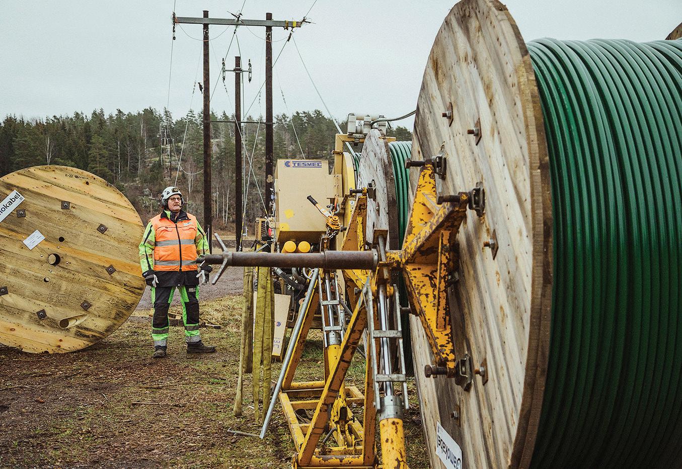
The Swedish utility has used lightweight covered conductor, or tree wire, for decades and has developed a budget outline to guide its investment.
By PETER IPSEN, E.ON

Often referred to as tree wire in the U.S., covered conductor is used widely by E.ON in Sweden to ensure power continuity for its customers as well as the safety of its line crews. The technology was developed by Swedish cable company Amokabel in the 1990s in response to heavy winter storms causing trees to fall on lines. It has been improved over the years into the product it is today.
In many cases, covered conductor maintains supply even when a line has been downed. However, E.ON aims to minimize any risk to third parties, so its line crews respond as quickly as possible and prioritize the order in which fallen trees are removed.

This type of lightweight covered conductor system was developed for restringing existing poles. Rather than being bare wire, covered conductor has three protective layers made from modern lightweight polymers. This prevents electrical faults by stopping tree branches and foliage from coming into direct contact with live conductors. It has been deployed widely across E.ON’s 89,000-mile (143,000-km) network, particularly on 20-kV lines running through forested areas.
E.ON has upgraded its entire network with covered conductor, and no longer has any bare wire. Now, its current focus is on increasing grid capacity. Sweden’s electricity demand is forecasted to double by 2045 due to growth in electric vehicles and heat pumps, as well as the connection of distributed renewables and the electrification and decarbonization of industry. Today, E.ON uses conductors with cross-sectional areas of 62 sq mm, 99 sq mm, 159 sq mm and 241 sq mm (122.4 kcmil, 195.4 kcmil, 313.8 kcmil and 475.6 kcmil), depending on loads. The utility foresees upgrading covered conductor lines to higher crosssections and higher voltages — for example, 52 kV — to cope with future demand and allow for spare capacity.
This rolling program has given E.ON extensive experience with covered conductor. The utility has developed a budget outline to guide its investment. The outline uses a typical project cost for three
phases of almost SEK 660,000 per km (approximately US$100,000 per mile).
This assumes a medium to challenging terrain in which a crew can cover 2 km (1.2 miles) per week. However, the timescales and costs can vary depending on the complexity of work, terrain and other site-specific factors. A project factor can be applied to account for more challenging conditions, while simpler projects away from roads are less costly because traffic management is not needed.
The budget accounts for 49 hours of engineering design and project management. This includes analysis of the line to evaluate the terrain and the procurement of materials, such as accessories, additional bracing and other site-specific needs. It also includes establishing a work plan, developing an environmental plan, and securing permissions and consulting with landowners, local authorities and road authorities.
Other costs include arranging permits for traffic closures and securing traffic barriers to protect line crews and members of the public.
When it comes to on-site labor, the budget includes 142 hours for E.ON’s line crews, which are typically three or four strong. Once on-site, they establish and prepare the site and put appropriate traffic management in place. The simplest approach is to have a guard in place during the line-pulling work. Then it is pulled without slack to maintain the line height in the intersection, or a catch line can be set up. In some projects, automated traffic lights might be used.

Electrical work starts with switching to temporary lines. The team checks the status of poles and mounts additional bracing and anchoring, if necessary. Then the team dismantles and restrings the conductor onto the existing poles and adjusts or moves some poles if needed. The next step is to make connections and carry out switching to return the line to live status.
The most cost-effective approach is to assess the condition of existing poles before starting work and beginning the outage. This means any need for pole replacements, repairs or reinforcements is known in advance and can be planned for properly.
E.ON’s policy during line renovations is to replace all end poles and angles as a preventive measure. These are the hardest to replace during a storm and take the most time. The utility believes this standard requirement is worth the additional cost.

When
or four strong.
Another important factor to consider when replace existing poles is — when changing the conductor, for example, from aluminum conductor steel-reinforced (ACSR) 62 to covered conductor 62 — it becomes almost like pulling up ACSR 99 in terms of forces and weight. So, it is important for the poles to
be dimensioned accurately. E.ON learned this the hard way when the covered conductor held up under fallen trees but the poles did not.
The budget outline also allows for materials, machine hire and other costs. The baseline cost is calculated based on restringing
● Nordic’s PSP-151530-MG-CB-FIBER pedestal is the enclosure for a fiber optic enclosure.
●Lockable & Removable lid allows open access foreasytrainingoffiber strands inside the flared base.
●Pedestal’s built-in mounting bracket makes it easy to attach the fiber optic enclosure.
●Large expansive interior cavity for easy fiber enclosure installation.
●Accommodates a variety of fiber enclosures
●The word “FIBER” is imprinted on the top lid.
●*Hand holes available for other fiber applications.


three phases using conductor with a cross-section of 159 sq mm (314 kcmil), one of the larger cross-sections E.ON uses. Accessories also are included for jointing, bracing and anchoring as well as for rerigging or adjusting poles, if needed.
When it comes to installation and handling of covered conductor, E.ON line workers have said it is similar to working with bare wire. In contrast, the alternative approach of undergrounding is similar to laying water mains or gas pipelines.
The type of covered conductor E.ON uses is based on a fully sealed system, which protects the line from water ingress.
This requires the use of connectors that pierce through the insulation to make an electrical connection between conductors, while a mechanical clamp holds the connector in place and seals the joint against moisture. Each connection can be completed within seconds, as there is no need to strip insulation to make connections.
Lightning protection is another important factor for covered conductor because lightning arresters must be installed at key points (equipment poles, covered conductor to bare and underground transitions, and dead-ends).
To ensure crews have the skills and knowledge to tackle any overhead equipment they might face in the field, E.ON has its own training camp for technicians and contractors.
The camp includes every type of equipment a connection technician might encounter on E.ON’s real-world network, including poles, overhead lines, earth cables, cable cabinets, cable terminations and network stations. Every type and configuration of pole on the network is represented, with composite and wood poles, as well as all types of angles and end poles.
A low-height area provides an opportunity for practical demonstrations and hands-on learning without having to work at height. The camp also includes small substation demonstrators for crews to learn about transitioning between underground and overhead lines.
Located in the Swedish town of Alstermo, the training camp has helped to cut development time and improve product quality since covered conductor technology was first developed in the 1990s. It is hosted by Amokabel, which is an immediate neighbor and a manufacturer of covered conductor. The camp gives E.ON’s line crews an opportunity to provide feedback to the manufacturer on their experience working with conductors and accessories.
While covered conductors were developed to protect power continuity for customers during Nordic storms, it also can be used for other applications. For example, it is being used in Australia to cut wildfire risk as it is fully covered to prevent sparking, while being lightweight and resistant to abrasion and ultraviolet rays
PETER IPSEN is a highly experienced Technical Expert at E.ON Energidistribution, Sweden. He specializes in the design, implementation, and optimization of energy distribution networks and is a long-term member of various technical committees, including SEK, the Swedish national standardization body for electrical standards.


Orlando Utilities Commission uses real-time monitoring to pinpoint why a large manufacturing plant was suddenly experiencing outages.
By MELVIN LIWAG, Orlando Utilities Commission; CHARLIE NOBLES and CORY STEWART, Ubicquia
Power quality is a cornerstone of reliable electrical service, particularly for large commercial and industrial customers. Poor power quality can lead to costly disruptions, equipment damage and operational inefficiencies, making it essential for utilities to ensure consistent and clean power delivery. According to the Electric Power Research Institute (EPRI) 2022 Power Quality Tech Newsletter, poor power quality costs U.S. businesses more than US$145 billion annually.
Power quality events can halt entire production processes, often occurring 20 times to 30 times per year, with a 1-second outage costing industrial and digital economy firms $1477 per second. A ResearchGate paper, the Consequences of Poor Power Quality — An Overview, by Sharmistha Bhattacharyya and Sjef Cobben of the Technical University of Eindhoven in The Netherlands, shows 70% of power quality issues occur on the customer side because of equipment operation and wiring, with the utility often shouldering the blame for poor power quality.
The technology to spot power quality problems and their causes — no matter whose side the issue is on — plays an integral
role in preventing future interruptions and outages as well as providing accurate information to forge a solid partnership with the customer.
Orlando Utilities Commission (OUC), the 14th largest municipal utility in the U.S., has long prioritized reliability — serving over 242,000 metered accounts, including 32,000 commercial and industrial clients, in Orlando of Orange County and St. Cloud of Osceola County. OUC’s 418-sq mile (1083-sq km) service territory includes significant installations such as an international airport, nationally recognized tourist attractions, major health care facilities, and large-scale manufacturing and supply chain operations.
For nearly six years, OUC provided uninterrupted power to a large manufacturing plant in Orlando, thanks to infrastructure designed for maximum reliability. The plant was served by three dedicated underground feeders and 10 three-phase transformers, eight of which were 2500-kVA units. These transformers

Network Operations Center (NOC) at Ubicquia headquarters.
were part of an engineered system featuring automation capabilities, such as auto-transfer switches that could switch to backup power sources within two seconds of a disruption. This
setup was critical, as it ensured the manufacturer could operate without interruption — even during hurricanes and daily thunderstorms, common in Central Florida.
You Should Turn to


•Undergrounding Research
•Webinars, White Papers & Presentations
•Reference Library & Helpful Links
•Power Delivery Expertise
As professionals from the North American power industry value chain, PDi2 members work to determine the most viable, reliable, resilient and cost-effective solutions for the installation of transmission and distribution systems. PDi2 educates stakeholders on investment decisions based on data-driven life-cycle cost analysis.
Join the Discussion Today!
For more information, go to pdi2.org, email info@pdi2.org, or call (703) 212-7745.

However, that changed in 2022 when the manufacturer experienced unexpected partial power outages and low-voltage events. These events caught the utility off guard, as the system had previously withstood numerous challenges, including Category 3 and 4 hurricanes such as Irma, Ian and Idalia as well as many tropical storms, without issue.
OUC began a thorough investigation to pinpoint the cause, deploying temporary data loggers and pulling historical data from meters to discover why certain transformers were blowing fuses. While these tools were effective for basic monitoring, the utility needed more detail to diagnose the complex power quality issues. Because two meters were connected to the customer’s 10 transformers, providing data every 15 minutes, and the data loggers only held two weeks of data, OUC installed two power quality meters to gather more precise data.
With access to more data points, the utility discovered that three transformers linked to the outages were overloaded. However, it still required more information to understand the root cause of the issue. Seeking to understand the partial outages better, the utility visited with the plant engineer and discovered the manufacturer had recently installed an 800-hp compressor and an entire process line wired to a fully loaded transformer. Each time the compressor started, it brought the transformer well above its current rating and caused bayonet fuses inside the transformer to blow several times.
OUC continued using its older monitoring equipment and discussed with the customer about transferring loads for better balance. At the same time, the utility discovered a solution that could obtain a real-time view of the customer’s power quality issues, especially the load profile, which could help the utility to be more proactive and prevent problems.
OUC learned from another utility about Ubicquia’s UbiGrid Distribution Transformer Monitor (DTM+) and UbiVu AI-driven asset management platform. During a planned outage, OUC installed UbiGrid DTM+ units on the three overloaded transformers.
The impact was immediate, providing OUC with real-time transformer load monitoring, voltage, internal pressure, temperature, and dozens of other monitoring capabilities upstream, downstream and in the transformer. For example, OUC can now monitor the customer’s load profile and see current spikes when a process starts. The utility can detect sags and harmonics, determine the origin and cause, and address them before outages occur or transformers are damaged.
Shortly after the units were installed, the manufacturer experienced another outage over the Christmas and New Year holidays. This time, OUC was equipped with real-time data, leading to a rapid diagnosis. An engineer was able to access the asset management platform from a laptop at home, pinpoint the cause down to the specific transformer and circuit — a blown bayonet fuse — and coordinate a swift response to restore power.
The information helped to guide the field technician to the right transformer to replace the fuse — without having to waste time inspecting all 10 transformers — and coordinate with the customer to reenergize.
With the real-time monitoring units, OUC can provide valuable insights to the customer. With the ability to see overloading transformers, the utility can provide this information to the customer for better load balancing. In turn, this improves reliability and extends the useful life of assets.


OUC can measure a wide range of grid and transformer health factors by monitoring primary current, secondary current and secondary voltage 7800 times per second to gain a more accurate picture of power quality issues. This enables measuring frequency, power factor, sags, swells, harmonic distortion, transients, and critical transformer health data such as temperature, pressure, load, pole tilt and impact. Health reports are delivered every two minutes, and alerts are sent immediately by text or email.
Ubicquia works closely with OUC’s power quality team, establishing alert thresholds and reports, while keeping the utility updated when new analytics capabilities are released.
Building on the success of the real-time monitoring units at the manufacturing plant, OUC plans to expand the technology to other commercial and industrial customers. Future deployments include applications at a new theme park with rides and hotels, opening in 2025, and possible deployments at a growing number of small satellite emergency room (ER) facilities, where reliable power is critical.
ER facilities require a high level of power quality due to the sensitive nature of imaging equipment. This can be challenging because some facilities must be served with overhead feeders,
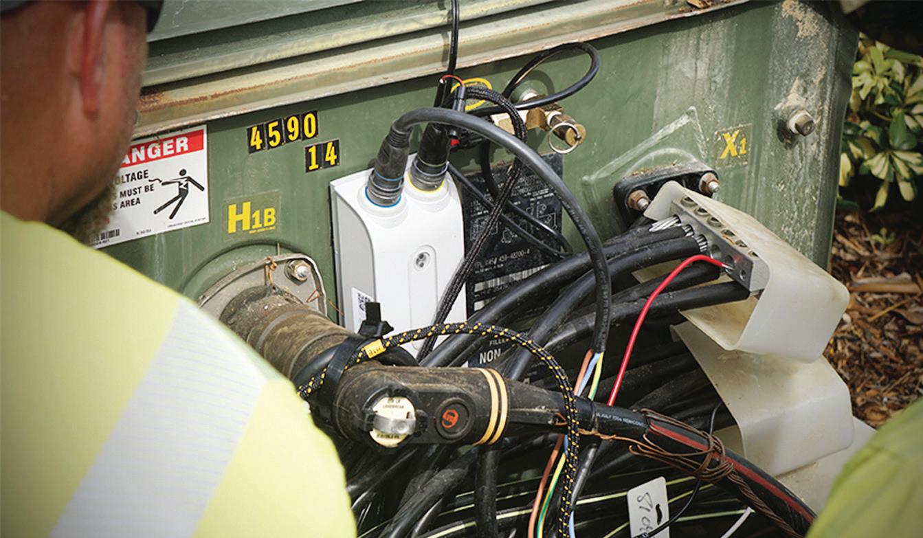
UbiGrid DTM+ pad mount installation.
making them susceptible to weather, vegetation and wildlife. With new monitoring and analytics capabilities on distribution transformers, the utility’s power quality team is focused on the feeders to improve reliability.
The journey from a sudden power quality issue to a successful resolution is a testament to OUC’s commitment to reliability and innovation. By embracing advanced monitoring technologies, OUC can ensure its customers receive the reliable service they depend on. As the utility looks forward, it sees the continued expansion of smart monitoring solutions playing a crucial role in maintaining and enhancing the reliability of Orlando’s power grid.

MELVIN LIWAG has dedicated 30 years to the Orlando Utilities Commission, establishing himself as an experienced electrical engineer within the electric utilities industry. With expertise in operations and construction management, Liwag excels in the distribution control center and trouble dispatch environment. He is proficient in smart grid project engineering and management, electric distribution design, reliability engineering, and avian and bald eagle conservation. An accomplished engineering professional, Liwag graduated from the University of Central Florida with a BS in Electrical Engineering.
CHARLIE NOBLES serves as the Vice President of Business Development for Ubicquia’s Smart Grid segment. With a focus on expanding Ubicquia’s market presence, he promotes the company’s innovative smart grid solutions, including the UbiGrid platform. Charlie brings a proven track record of success from his tenure at Progress Energy (now Duke Energy Progress) and Sensus, where he delivered key utility solutions to a diverse set of global utility companies.
CORY STEWART is the Utility Solutions Architect for Ubicquia’s Utilities segment. He supports sales teams as a technical SME for presentations and deployments, both in person and remotely. Cory installs UbiGrid DTM+ units on transformers, sets up customers on the UbiVu network, and designs and administers training on product usage. He advises customers on maximizing the benefits of transformer monitors. Cory has over 15 years of experience in technology consulting, including smart grid consulting and power quality analysis.

RTDS Technologies is celebrating 30 years of the RTDS Simulator – the world standard in realtime simulation and hardware-in-the-loop testing. The RTDS Simulator revolutionized the testing process for control and protection systems when it was introduced to the power industry. Today, the technology is at the heart of innovative laboratories in more than 57 countries around the world. Leading utilities, manufacturers, research and educational institutions, and consultants rely on the RTDS Simulator to de-risk new technologies for a secure energy transition.


The electric utility industry is at the forefront of infrastructure related optimization efforts when it comes to addressing the complexities, cross-industry issues, and regulatory challenges.
By PETER ARVAN MANOS, ARC Advisory Group
For all industries, the T&D World Live Conference in Atlanta, GA had very compelling sessions across five tracks of importance, including: AI and Digitalization, Distributed Energy Resource Integration, Electrification and eMobility, Grid Resiliency and Black Sky Hazards, and the Future Transmission & Distribution Grid.
The electric utility industry is at the forefront of infrastructure related optimization efforts when it comes to addressing the complexities, cross-industry issues, and regulatory challenges associated with clean energy, e.g., for freight transportation,
or for heat to replace fossil fuels in industrial processes, or for clean energy for feedstocks in other applications.
Electric service restoration efforts in response to Hurricane Helene are the largest utility industry mutual aid assistance mobilization in U.S. history. Tens of thousands of utility crews from all over the U.S. have been participating in restoration efforts. The scale and depth of the storm’s destructiveness in some areas of the Southeastern U.S. is requiring a full rebuild, rather than mere repair, for portions of impacted T&D systems. While this reduced utility attendance somewhat at the conference, nonetheless, personnel from utilities and their solution and service provider communities participated in numerous productive meetings and panel sessions.

Heroic utility line workers’ collaborative spirit was praised at the conference. Cross-industry collaborations at the conference are also praiseworthy. Utilities’ long-standing traditions of mutual aid point to key wider trends,
because much greater cross-collaboration was evident at the conference in other ways that span across industries who share risks associated with infrastructure and supply chains, including those associated with energy and with transportation, all of which rely directly and indirectly on electric utility service.
Growth areas are impactful, for example, for the oil & gas, chemical, mining & metals, and diverse manufacturing industries, given the economic value and other benefits associated with electrification and replacement of highly GHG emissive processes with cleaner energy sources ranging from renewable electric power to hydrogen to other sources.

To achieve success, innovations driven by competition are an important factor. But it will be insufficient. We also need greater collaboration, and a vision on the part of industry that can appropriately position policymakers to enable the infrastructure resources we all share.
The integration of wind and solar on the electric grid is an enormous success. At a presentation by the California Independent System Operator (CAISO), the fact that the drop in solar output during a partial eclipse last year was handled routinely amazed this analyst, when noting that the one hour drop in question represents roughly the same amount of electric generating ca pacity required to support the five bor oughs and surrounding suburbs of NYC in Con Edison’s territory on a typical day. Con Edison’s current peak is at around 13,000 MW, and when I worked there as an engineer in the mid 1980’s, it was a big deal when peak demand of 10,000 MW was exceeded for the first time — and now this is just a blip on a cloudy day for CAISO’s dispatch of power to compensate for intermittency of solar power…if such fluctuations can be predicted as reliably as a solar eclipse can be predicted.
The ability to integrate renewables, and, going forward, to integrate electric vehicles of all kinds, both require tremendous im provements in the robustness and real-time capabilities of industrial data fabrics in support of advanced analytics, and in the digitation of the electric grid.
At the conference key challenges came to the forefront, along with great successes in meeting some of industries’ prior big
challenges as exemplified by the integration of solar in California mentioned above.
Many of us have said it is good, in the energy transition, to take an “all of the above” approach, one where we support many different tracks on the path to resilient, economical, and reliable energy supplies. But the challenges that came to the forefront during this conference led me to look at the “all of the above” approach with some newfound skepticism. There are several reasons.
First, the use of certain clean energy solutions needs to be seen in a realistic context where different options are viewed and compared in practical ways. Some technologies are less


viable than some people suggest, when it comes to their capacity to economically be reliable elements for new energy supply to meet all the new electric load coming on board. Second, it is not a question about such sources having sufficient technical feasibility. Instead, it is about their only being able to contribute a small portion of the needed capacity.
Two such examples are the use of farmland to create fuels off of the crops grown on the farmland, and second, the creation of biodiesel from reclaimed cooking oil:
• The energy efficiency of PV solar panels is about ten times higher than the rate at which plants convert sunlight to energy, and the use of farmland for “energy crops” instead of using it for crops in our food supply, should generally be shunned, since such high-cost energy sources also elevate food prices. And while making biodiesel from waste cooking oil is a better use of the waste cooking oil, than disposal of the oil in landfills, it is not going to be an important element of our energy mix.

regarding their positioning around hydrogen going forward.
• While my colleagues at the conference laughed when I pointed it out, they agreed with my suggestion that we would all have to increase our consumption of fried foods ten-fold to a hundred-fold, for biodiesel from cooking oil to be any sort of “pillar” of our clean energy supply. It should not be touted as such, but instead should be viewed, simply, as a better way, from a circular economy point of view, of “disposing” of waste cooking oil.
Three big challenges discussed at the conference included the challenges associated with clean hydrogen, the promise of transportation electrification, and finally the unprecedented growth in electric power demand and T&D build-out associated with the massive new data centers quickly being added to our infrastructure.
The benefits of clean hydrogen, if it could be economically pro -
The various technologies for, and challenges of, clean hydrogen were delved into in detail, including the vulnerability of welds in most of our natural gas utility pipe infrastructure to become embrittled if the amount of natural gas put in the mix exceeds 10%. The depth of industrial dependencies on hydrogen currently was highlighted, as was how small the current production levels were for clean hydrogen vs. the volumes of hydrogen in existing use cases overall.
Electrification of transportation will increase the economic and environmental benefits of clean electrification enormously, but will also require a massive increase in the ability of our infrastructure to utilize real-time data and control systems to run optimally and to create new markets for all participants (including drivers of passenger EVs and operators of EV freight trucking fleets). The complexity includes optimizing battery charging and routing of vehicles with widely varying needs.
A fascinating example of the complexities involved was around the benefits of regenerative braking systems on EV freight trucks, since such brakes not only help to charge the battery, but also help to extend the useful life of the friction brakes. If a truck is going to leave its charging station at a higher elevation than its first destination, its battery should not be charged to 100%, since it will exert undue wear on its brakes while going downhill and will lose an opportunity for some “free” charge off the regenerative brakes. A limiting case example given involved an actual use case of a massive EV truck at a mine at the top of a

hill, which charged itself with regenerative braking while going downhill with a full lode of ore, and which was then able to go, empty, back up the hill “for free” in effect, not needing to have charging infrastructure installed for this use case.
The ability to build new electric infrastructure to charge large truck fleets is key, and is daunting, given timing, costs, and real estate issues involved. Many truck depots are in dense industrial areas where real estate to add new electric substation capacity may not be readily available. Many depots lease their space from landlords who have no interest in building out EV charging infrastructure. Seaports came to the forefront as a growing area where such infrastructure can more often be readily built, and where trucks are often going anyway to pick up cargo. Pilot programs for fast charging capabilities, and even for inductively charging with no physical connection between the charger and the truck, were discussed.

Finally, the other big challenge involved how new data centers are being built rapidly, and are enormous, with some coming in at 1,000 MW per data center (i.e., 10% of NYC’s total electric power demand, per data center!). The plans to build or upgrade needed substations and T&D infrastructure often go on fast tracks with these data center projects, based on the enormous demand for the compute power of these data centers, and the deep pockets of the investors involved. They typically, contractually, are expected to run at near 100% of their rated capacity, 24/7, so there is little or no option for most of them participating in peak demand reduction programs to help keep the grid up and running more reliably and economically — the exception is a smaller subset of data centers that are not dedicated to large language models or other AI-driven use cases, but instead have more flexibility to shift load if it is of economic benefit (e.g. this group includes Bitcoin mining data centers).
The three challenges mentioned above are interconnected and can be recast as opportunities.
While new installations of T&D switchgear can enable the faster control capabilities that are needed for a more dynamic grid to take on massive increases in electric vehicles, the existing infrastructure, including capacitor banks, involves
electro-mechanical relays and control systems that cannot respond fast enough for optimal grid operations. Ironically, the tremendous growth spurts in demand for electricity to support new data centers for AI and cloud-based industrial data fabrics, functionally, will be enablers for the more dynamic grid, since the data center’s support for AI and data fabrics is precisely what is required to run the grid in the new ways it will need to be run — so utilities and their industrial, commercial, and residential end users will be among the key users of the new data center’s offerings.
Words matter, and the word “sustainability” has its place, but “risk reduction” is the better term here, in the context of recommendations for how to address our challenges better. And the risk of not stepping up is too great here, vs. the risk of stepping up, to meet the challenges, if they are seen clearly.
Risk reduction should be a cross-industry cultural mandate, and should ideally become embedded in a new generation of better regulatory and market-building structures. It became clear to me during the conference that we need as stern and strict a set of regulations being imposed on the local, state, and federal policymakers, as on industrial and public interest stakeholders. To meet 2050 goals requires a shared vision.
Enter full lifecycle costing capabilities, of a next-gen character. They should build upon, but go far beyond, what we used to call good old “engineering economics,” and should go hand in hand with build-out of big models to support better decisionand policy- making. In the context of energy transition and


industrial sustainability, ARC recently articulated related trends with regard to a System of Systems (SOS) approach.
The best risk reductions are those that are entered into in a collaborative way, per the utility industry’s mutual aid assistance example. The business model upon which mutual assistance was built has been a great success. But it evolved in response to storm situations of the frequency and scale of the past, and, like other infrastructure and severe weather challenges, requires new refinements and improvements.
As was mentioned during the conference, the increasing frequency of line crews being called away to help in restoration

efforts is starting to have negative impacts on the maintenance of the home utility’s T&D systems. A start related statistic is that there have been as many Category 4 and 5 hurricanes in the US in the last 8 years, as in the prior 56 years — an 8-fold increase. Smarter T&D infrastructure, and better hardened T&D infrastructure, represents a shared resource of the industrial and commercial and residential end users who will be enabled to participate in new value areas of economic benefit to all participants.
If, and when, the new smarter T&D infrastructure gets built out, with the needed more real-time capabilities, there is still a regulatory disconnect that must be addressed, one for which, hopefully, the above-mentioned lifecycle costing, and big models, will be deployed. The utility example here has its counterpart in other industries: T&D infrastructure, and underlying baseload power generation infrastructure, has a 2x to 10x longer useful life, than the assets it is being connected to. Below, to provide context for the above recommendations, some examples are shown.


• If a truck depot electrifies, can the investors or regulators who fund and approve the T&D build-out be guaranteed that the electric capacity to charge the truck fleet will be needed after the (relatively much shorter) useful lives of those electric trucks have passed? What if hydrogen replaces electricity as the best fuel source for the freight trucks of the future?
• What if a regulator approves a microgrid at a location, whose economics were a function of the need for power at the end of a certain line, and the economics are ruined by some non-regulated build-out of power generating capacity from some competitor — what is the responsibility of the regulator to the microgrid owner who got permission to build the first facility?
• Similarly, what if some of new data centers being built this year are replaced at other locations by other data centers in a decade or two, at a point in time when the new T&D and generation infrastructure that was built to serve those data centers is still “young” and largely undepreciated?
PETER ARVAN MANOS is Director of Research, Electric Power and Smart Grids, at ARC Advisory Group. Links to his recent work can


The 2024 competition marked the 40th year of the event with more than 1,000 competitors.
By AMY FISCHBACH, Field Editor
The spirit of the International Lineman’s Rodeo has lived on for 40 years. It’s a legacy and tradition that has connected lineworkers worldwide through competition and camaraderie.
Dale Warman, one of the founders of the Lineman’s Rodeo and a 2019 inductee into the National Lineman’s Hall of Fame, says the idea for the Rodeo was inspired by the cowboys, but is all about the line trade. Every event includes skills that lineworkers routinely perform out in the field — whether it’s scaling a wood pole, working with hot sticks and rubber goods, tying a knot or replacing a blown fuse, tie or cutout.
“When we started this, it was all about one thing — it was by linemen, for linemen and about linemen,” he said. “The whole idea was that linemen and their families could enjoy themselves, get away from work and compete in a friendly competition to show their families what they do. It worked well, and it got bigger and bigger.”
While the event launched with only a dozen journeyman teams in 1984, the event has experienced explosive growth to well over 1,000 competitors. In 2024, 227 three-member journeyman teams and 380 apprentices showcased their skills in the hurtman rescue, pole climb and mystery events on the Rodeo grounds.
One of those journeyman teams consisted of three brothers — Jordan, Keith and Tate King — from Xcel Energy in Colorado. Tate King says it’s awesome to be able to be on the same team with his brothers, not only in real life, but also in the trade.
“My dad was a lineman also, and I think he’s proud of us,” King said. “We work together, we go through practice and try to get ready for the Rodeo.”
Due to back-to-back hurricanes in the Southeast just before the event, not all the competitors were able to travel to Kansas City for the Lineman’s Rodeo Week due to ongoing rebuilding and restoration. Those apprentices and journeymen lineworkers who were able to compete, however, kicked off the competition a little before 7:30 a.m. on an unseasonably warm October morning at the Agricultural Hall of Fame grounds in Bonner Springs, Kansas.
Following the American and Canadian national anthems and moment of silence, the announcer signaled the competitors to head to their first events for a full day of competition. Like last year, all the events had to be conducted in full fall restraint, and no free climbing was allowed.
The competitors could also compete in five different divisions — investor-owned utilities; REA, REC and electric cooperatives; municipals; contractors; and military. Within the journeyman bracket, those competitors aged 50 years old and older could also compete at the senior level on journeyman teams. Throughout all the events, the volunteer judges evaluated the competitors on five
main criteria — safety and safe work practices, neatness and ability, equipment handling, timely completion of the event and the ability to follow all event and general rules.
As such, the competitors had to not only try to complete the events quickly but also safely by following all the rules and regulations. Otherwise, they could lose event points and the opportunity to be honored on the stage at the awards night. By watching other lineworkers in action, it gave the competitors like OG&E’s Jeff Stith the opportunity to learn from others.
“It’s our second time competing together, and my favorite part of the Rodeo is the events and the climbing,” Stith said, who was on a journeyman team with Trent Massey and Todd Munson. “It’s a good time and a family event. The weather is beautiful out here, and it’s fun to see all the different competitors from different locations interact with everyone.”

While the roots of the Rodeo are in the Midwest, teams from all over North America now compete at the Rodeo, which has also attracted interest from visitors from England, Brazil, Jamaica,

Poland, New Zealand and Australia among other countries. Canada often has teams competing on the international level at the event. For example, Manitoba Hydro sent two apprentices and three journeyman teams to compete at the 2024 International Lineman’s Rodeo. Chad Williams, a journeyman powerline technician for IBEW 2034 and Manitoba Hydro, competed as an apprentice eight or nine years ago. For this year’s competition, he was on a journeyman team for the first time with Jared Flaman and Matt Lake. The trio finished in the top quarter of all the journeyman teams.
“I love the Rodeo,” Williams said. “It’s cool to see where people come from and how they do it a little differently.”
In the line trade, lineworkers must work together to keep the power flowing and the lights on. Just as they serve on crews back home, the journeyman teams must also compete in teams of three to finish four different events with the maximum number of points in the minimum time frame. Two journeymen serve as climbers while the third member of the team works as a groundman.
As in years past, the journeyman teams had to compete in a hurtman rescue event on a 40-ft wood pole. All three members of the journeyman teams had to participate in the event simultaneously, with the climbers rescuing the mannequin and the groundman using the extendo to open the switch and then laying the hurtman on the ground. The Habersham EMC team of Tucker Dyer, Dillon Welborn and Robert Morris scored the full event points with a time of 01:27:66, earning the top spot in this event in the journeyman division.
Another traditional event, the pole climb, tasked journeyman teams with climbing and descending

the pole without breaking the raw egg. The climber carefully places the raw egg in a small bucket, scales the pole, drops down an empty bucket at the top of the pole, places the egg in his or her mouth, hangs the new bucket on the hook and then climbs down. Once on solid ground, the competitor must show the egg to the judge, who will inspect it for any cracks, which incurs a 10-point infraction.
Ameren Illinois captured the top three spots in the journeyman division in the pole climb with the team of Jacob Carr, Buck Rodgers and Teddy Brinkoetter coming out on top with a time of 1:09:15.
While the journeyman teams could practice back at home for the hurtman rescue and pole climb events, they didn’t know the ins and outs of the mystery events until they arrived in Kansas City for the Rodeo Week and picked up their packets. For the first mystery event, the teams had a maximum time of 17 minutes to replace a bad C-neck tie. The simulated energized event required the journeymen to use materials including shotgun sticks, hoses, a split blanket and more. The IBEW Local 1245 team of Josh Klinka, Dustin Krieger and John Damas inched out the competition with a 10-second lead and a time of 08:34:04.
For the second mystery event, the journeyman teams had up to 20 minutes to replace a solid blade non-load break cutout serving a single-phase tap line at 4 kV. The PG&E/IBEW Local 1245 and SCE Local 47 team of David Angove, Brandon Gloria and Floppy Hunt climbed up to the top of the event with a time of 06:38:28.
The team that won the grand championship trophy, however, hailed from the Marion Operating Center of Ameren Illinois and included Jason Novak, Clayton Gulley and Austin Lewis. The team, who were crowned the best of the best of the journeyman division, were one of only seven teams with a perfect 400 event points and no deductions, but they accomplished it in the lowest time of 20:05:30. Novak says winning the title, “Best of the Best,” was an amazing feeling.
“We practiced hard, but it takes a special day to win it all against the most elite competitors in the world,” Novak said, who has competed at the International Lineman’s Rodeo for more than 20 years. “We developed a game plan before each event, but anything can happen, and we adjusted on the fly. I couldn’t be prouder of how my teammates performed and how the other Ameren competitors did as well.”
Once apprentices have completed four years of their apprenticeship and meet certain criteria, they can compete on journeyman teams, but until then, they must go solo at the Rodeo.
Zackery Goff, a fourth-year apprentice for Pedernales Electric Cooperative, got a three-peat by winning the apprenticeship division, not once, not twice, but three times in a row. Along with winning first place in the overall apprentice category, he also placed first in the REA division, second in the written test category and fourth in the hurtman rescue. He says when it comes to competition, the nerves still definitely kick in, regardless of any wins in the past.
“I really enjoy competing and seeing what I can push myself to do,” he said. “Paying attention to the details is important, and I like the safety aspects of Rodeo competitions, knowing it’s helping me to become better at my trade. It’s also fun being around other people and meeting folks at International.”
For the written tests, he put in a lot of time studying on his own time to learn the material, and for the hands-on events, he says there are many secrets to success on the apprentice level.
“I think it’s a combination of the hard work and practice I’ve put into it, coupled with the mentorship I’ve had through other people taking the time to teach me and help me along the way,” he said. “I’m grateful for that and all the support.”
For 2025, Goff must compete at the journeyman level once he tops out at PEC.
“It’s bittersweet knowing I finished my last competition as an apprentice, but I’m excited for the next phase of my career and look forward to continuing to learn and grow, and hopefully be back next year competing as a journeyman,” he said.
Like the journeymen lineworkers, they must also compete in two mystery events, the pole climb and the hurtman rescue, but they must also take a written test the day before the Lineman’s Rodeo. The 50-question test, which uses multiple choice and true/false questions, is based on content from the 14th edition of The Lineman’s & Cableman’s Handbook. Aaron Paisley, apprentice for Snohomish County PUD, captured the win in the


written test event with only six deductions, which put him ahead of the pack at 94 points.
Like the journeymen teams, the apprentices also had to showcase their skills on pole climbing, which is often something they practice for hours at a time during their apprenticeships. Jack Fletcher from IBEW Local 42 won this event


with a total time of 00:35: 22 and no deductions.
Because it’s important for not only journeymen, but also apprentices to know what to do in the event of an emergency, the apprentices must also compete in the hurtman rescue. Apprentice Clayton Tanner from Ameren Illinois swept the division with a total time of 01:05:50 and a perfect number of points.
The apprentices also had to compete in two mystery events, but they were completely different than those for the journeymen. For the first mystery event, they had up to 11 minutes to complete a transformer outage restoration. They first had to use a telescopic stick to remove the simulated blown fuse. Once the barrel was down and the stick was collapsed and back on the tarp, they could tool up or replace the blown fuse link. After adjusting their fall protection, they could then climb to the


proper working height to retrieve the 8-ft shotgun and remove the squirrel. After returning the shotgun to its location, they had to climb down the pole, replace the blown fuse link and rehang the fuse barrel. Hunter Walton, an apprentice for Flint Electric Membership Corp., won this event with a time of 03:35:61.
For the final mystery event, apprentices had 15 minutes to finish an obstacle course by completing varying tasks at different spots on the pole. For example, they had to ascend the pole and remove the old tie wire and tie pad from the conductor without using knives. They then had to install the new preformed tie wire and tie pad. They also had to exhibit one of the foundational skills of the line trade—rope tying—by tying the two 10 ft tails together with a square knot. Dwight Diaz from IBEW Local 47 finished the event 16 seconds ahead of the closest competitor with a time of 04:33:56.
Following the day of competition, the lineworkers and their families came together for the final time at the awards banquet. The Overland Park Convention Center exhibit hall was transformed into a banquet venue with thousands of competitors and supporters cheering on the victors.
The ceremony began with a performance by Blane Howard, a Nashville recording artist. He revved up the crowd with his take on country classics by musical groups such as Brooks & Dunn with lyrics focused on the hard-working line trade. Next, the ILRA showcased the 40th anniversary video commemorating the history of the event and looking to the future of the International Lineman’s Rodeo.
At the banquet, Dennis Kerr, the co-chair of the ILRA, also honored the 20 scholarship recipients for 2024, and Andy Price from the International Lineman’s Museum inducted six new
individuals for the 2023 class into the Lineman’s Hall of Fame: Hazel Bush, Chad Dubea, James Bowden, Brady Hansen, Mike Hennesey and Harry Reeves. Jason Novak and Paul Koehler, journeymen lineworkers for Ameren Illinois, also brought their families up on the stage to present a check for $83,484 for St. Jude Children’s Research Hospital as part of the 2024 Climbin4kids fundraising campaign.
Another highlight of the banquet was the recognition ceremony for the first Kids Rodeo, organized by Missouri Valley JATC and sponsored by Buckingham Manufacturing. One of the 11-year-old competitors, whose dad is a lineworker for Evergy, says he had fun rescuing a giant teddy bear off of a tower mounted to the back of a truck for the “Teddy Bear Rescue.” Kessler Hilson won first place in the eight- to 10-year-old age group, “1st Step Apprentices,” and Jake Milhoan won the 11- to 13-year-old age group, “Future Lineman.” Both winners were presented on stage with a child-sized championship belt, just like those worn by the grand champions at the International Lineman’s Rodeo.
After honoring the winners of the Kids Rodeo, the ILRA began announcing the names of the top apprentices and journeymen lineworkers in all the events and across all the divisions at the 2024 International Lineman’s Rodeo. Many of the winners received plaques while the top performers brought home trophies for being the “best of the best” in the line trade.
To learn more about the winners and to see more coverage of International Lineman’s Rodeo Week, stay tuned to the Line Life Podcast at linelife.podbean.com and to our website at www.tdworld.com/electric-utility-operations , where we celebrate the line trade not just during Rodeo Week, but year-round. Also, mark your calendars for the 2025 Rodeo, slated for Oct. 15-18, 2025.
BY AMY FISCHBACH, FIELD EDITOR
Bryce Zahn, who competed at the 2024 International Lineman’s Rodeo, recently returned from storm duty restoring power following Hurricane Helene. To learn more about his experiences with this hurricane restoration, listen to the Line Life Podcast at linelife.podbean.com.

I got my foot into the door as a groundman working on a Vac-Tron truck and various other URD work such as boring and stubbing transformers for line installations. I did not go to boot camp or a line school. I had no previous experience really except for a few years working for Comcast.
Working on power lines and in the electrical field has always been something that interested me for years. It wasn’t until the age of 32 I made the decision to pursue this field. I knew one or two people who were lineworkers but they had never talked about their careers. I made numerous phone calls to the union, MoValley and friends and eventually began working as a groundman for Capital Electric. From there I eventually started my apprenticeship and next year I will top out as a journeyman lineman.
As a seventh-step apprentice, I’m currently on an overhead dock crew learning many different things from switching, reconduct jobs, pole changeouts, maintenance work, even some URD, and many other things. My work day currently runs from 7 a.m. to 3 p.m. I am on a three-person crew and am the only apprentice. Our work focuses on dock work for Evergy. I am trained through the experiences we encounter with the work Evergy gives us each week.
• Is a seventh-step apprentice who recently competed in the apprentice division at the 2024 International Lineman’s Rodeo.
• Enjoys spending time with his wife and four children, eating at Texas Roadhouse and helping others. He also loves to hunt and fish.
• Learning how to use meters, different powered hand tools and digger derricks during his apprenticeship.
• Encourages aspiring apprentices to never stop learning and always look for ways to improve and sharpen their skills.
• In the future, he sees the need for grid infrastructure improvements and expansions.
It is challenging to travel to get the required experience especially when you have a family. It’s also difficult to keep up with the bookwork from the JATC.
I think there are a lot more resources available to apprentices now, and the book work is probably more advanced than in the past.
Working storms for me is the pinnacle moments of what I do. I enjoy them thoroughly. I love to help people. I love the giving spirit and the spirit of unity and gratitude that overcomes everyone involved. The working conditions are tough sometimes with long hours, little sleep and being away from your own family. All of these things are part of storming though. It gives me a great sense of pride to work on storms.
I love being a part of this trade. It’s very rewarding and storming is my favorite part. Turning people’s lights back on in a time of loss and devastation is very rewarding.
It takes a good attitude, a good work ethic and perseverance. I would say my best quality is the work ethic my parents helped develop in me.
To stay safe in the field, you must use safe work methods, proper PPE and fall protection correctly.
I see myself as a journeyman lineman and hopefully a foreman eventually. To reach this goal, I plan to continue working hard and learning everything I can possibly learn.
Editor’s Note: If you would like to nominate an apprentice for Faces of the Future, please email Field Editor Amy Fischbach at amyfischbach@gmail.com. All profiled apprentice lineworkers will receive a tool package from Milwaukee Tool.

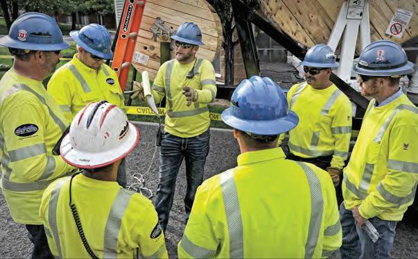
Lineworkers and their families come together to learn about safety, swap shirts and explore the Expo.
By AMY FISCHBACH, Field Editor
For the line trade, it’s all about keeping the lights and power on for customers. For one special week each year, however, lineworkers and their loved ones travel to Kansas City for the Lineman’s Rodeo. The event celebrated its 40th year in 2024 with line apprentices and journeymen lineworkers from all over North America and supporters from around the world.
To get the Lineman’s Rodeo Week off to a safe start, the International Lineman’s Rodeo Association (ILRA) partnered with its sponsors — Honeywell Salisbury, NECA, Tempest Energy and IBEW Local 47 and 66 — to present a one-and-a-half-day Safety and Training Conference at the Overland Park Convention Center.
“Hopefully these two days will help you guys and gals to be safer on the job,” Chad Schimpf said, a journeyman lineworker for Ameren Illinois who led this year’s safety conference after sharing his personal injury story two years ago. “That’s what the safety conference is all about.”

About 300 people registered for the conference, which was a good turnout for the 40th anniversary of the Lineman’s Rodeo, says Rustin Owen, a member of the ILRA safety and training committee and safety observer at the International Line -
man’s Rodeo. Along with line apprentices, journeyman lineworkers and supervisors, students from Metropolitan Community College-Kansas City actively participated in the safety discussions. Owen says it’s very important for students to attend and learn more their future careers in the line trade. It also reinforces the importance of safety, not just in the classroom, but also when they move out into the field and start their apprenticeship programs.
Beyond the line students, several journeyman lineworkers from the 249th Engineer Battalion also attended the con ference. Owen, who helped to start the U.S. Army Prime Power training school for lineworkers at Fort Leonard Wood in Missouri, says he appreciated having them in attendance.
“I worked very hard to build that school for the Army linemen and seeing the teams grow to this amount has been great,” he said. “It’s almost like having a legacy that you get to see grow every year. It’s very important to me and I love to see them in the safety conference to press that on.”

This year, the conference focused on everything from proper hydration and heat exhaustion to situational awareness and personal protective equipment. Because lineworkers often work outside in extreme temperatures, they can often get prolonged exposure to heat. The attendees learned how to protect themselves against the dangers of dehydration by listening to the keynote presentation by Dylon Koch from the Working Athlete. Koch told the lineworkers that to keep their bodies in proper working order, they must focus on proper hydration.
“The most important piece of equipment you own is your body,” Koch stressed during his presentation. “We can have the best fall protection, hard hats and PPE, but if your body shuts down, none of the other stuff matters at the end of the day.”
ments. Throughout many of the presentations, the speakers discussed possible future changes to safety practices due to this standard, Owen says.
“This year we’re focusing on some of the new regulations with OSHA and heat stress and things of that nature,” Owen said. “We’ve had people come in and talk about hydration, how important it is and the fabrics that are going in with it.
”For example, Brad Sipe from Lakeland Industries described moisturewicking FR fabrics and their role with heat and cold stress. He also emphasized the importance of proper layering of FR clothing for maximum comfort and protection.
The conference not only educated the attendees about PPE, but also situational awareness. For example, Ryan Kearney from Critical Incident Preparedness

point home, they also engaged in a demonstration on stage on what to do if a


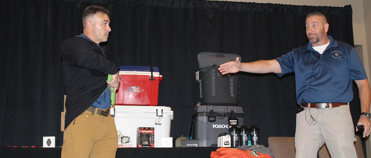


from Sydney, Australia to Kansas City to share his story.
“I’ve been in the industry for 22 years, and this has always been something on my bucket list to come and see the Rodeo and how you guys do it over here,” Bryn said. “I’m keen to explore different contacts and collaborate with different utilities. We have a growing population in Australia and a lot of infrastructure development, and I’m sure we can learn a lot from each other.”
During his presentation, he talked about damage prevention and public safety and how different workers interact with power lines.
“There is a lot of situational awareness that needs to be thought about, planned for and prepared for on work sites,” Bryn said.
On the first day of the conference, the attendees also learned about crew leadership from Eric Kapitulik from the Program Leadership. Before his presenta -
tion, he shared his thoughts about what makes a good leader.
“Just because you are a lineman doesn’t mean you are a great supervisor of linemen,” he said. “We have to develop our people. Most organizations do a great job of developing technical skills, but we need to develop leadership skills too.”
During the second day of the conference, lineworkers once again had the opportunity to hear a personal injury story, this time from Josh Simpson from Ameren Illinois. Mike Starner from the National Electrical Contractors Association also explored the progression of safety from the past to the present to the future, and Deb Short from Ameren Illinois rounded out the 2024 conference with her session, “The Keys to Longevity.”
Following the morning safety conference,


hundreds of conference attendees rode the escalator up to the second floor, where they lined up for the 2024 International Lineman’s Expo. They formed three lines to enter the doors of the Exhibit Hall, where they could participate in raffle drawings, test out tools and technologies and pick up giveaways to bring home.
Scott Woodruff, apprentice lineworker for Eversource Energy, says his company brought out two journeyman teams and
three apprentices from Connecticut. After competing in the regional Connecticut Rodeo for two years, he says 2024 was the first time he competed at the International Lineman’s Rodeo.
“I thought I had the best job in the world until I became a power company lineman, and then I realize I now have the best job,” Woodruff said, who worked for a utility company for 22 years before switching over to a power company. “At times, you get to travel out of your area to do mutual aid for other people, but


mostly, it’s that I enjoy the work and the people I work with.”
The Lineman’s Expo, which featured a record-setting 202 exhibitors, including 50 who are new to Rodeo Week, connects the manufacturers with the field users. This experience empowers the lineworkers to voice their opinions about what they like or want to change about certain products.

“It’s good to speak with the companies


who make the tools that you actually use out there and to see what’s coming out next,” Woodruff said. “We don’t know how good we’ve got it or don’t have it until the next thing comes out.”
Lineworkers could not only explore the show floor during the Expo in the exhibit hall, but they could also talk with exhibitors on the Rodeo grounds. One of those outside exhibitors, Sim -
ple Strap, enjoyed being part of the Rodeo Week.
“It’s one of those things that once you learn what the linemen do, keeping the energy on, they are invaluable to America,” said Ben Komer, co-founder and co-inventor of Simple Strap.
After three days of education and explor-

• Stringing Blocks
• Block Attachments
• Grounded Stringing Blocks
• Helicopter Stringing Blocks
• Fiberglass Hot Arms
• Chain Hoists
• Compression Tools & Dies
• Cutting Tools


• Impact Wrenches
• Magnetic Drill Presses
• Battery Tools
• Hydraulic Pole Pullers
• Traveling Grounds
• Groundsets & Jumpersets
• And much more!
ing the trade show floor, the attendees geared up for the one of the biggest nights of the year for the line trade, other than the awards banquet — Trade Night. They stuffed duffel bags with shirts and slung them over their shoulders as they walked in to set up their merchandise on the long tables, which stretched from one side of the first floor to the other.

This year, many of the shirts featured patriotic and lineworker-themed designs, and each one had a unique color scheme and story behind it. For example, Tom Jeffers, a journeyman lineworker for SWLCAT, says they work in the Arizona desert with a lot of rattlesnakes, and they hot stick most of their primary.
“I got the concept of a guy up on a nice Arizona morning, rattlesnake on the pole and a stick on the center phase,” he said. “It’s an inspiration from the AC/DC song, “Inject the Venom.”
Mass Electric, which sponsored the registration at the International Lineman’s Rodeo Week, made a limited edition run of 200 of its black long-sleeved shirts, which featured a glowing blue design. Meanwhile, Chris Kelley, a journeyman lineworker for San Diego Gas & Electric (SDG&E) and Local 469, was trading his company’s shirts featuring a silhouette of a lineworker against a California sunset with palm trees.

•
•


Strin in Blocks


• Helicopter Strin in Blocks


• Fiber lass Hot rms


• Chain Hoists


• Compression ools & Dies


• Cuttin ools


• Impact renches


• Ma netic Drill Presses


• Batter ools


• H draulic Pole Pullers


• ra elin Grounds


• Groundsets & Jumpersets


• d much more!
After swapping shirts, caps, stickers, glasses and more, the lineworkers headed up the escalators to enjoy Kansas City BBQ and relax with their teams and loved ones before competing in the 40th year of the Lineman’s Rodeo. For four decades, the event has allowed lineworkers to safely showcase their skills, connect with their brothers and sisters in the line trade and have their families cheer them on at the sidelines.
AMY FISCHBACH (amyfischbach@gmail.com) is the Field Editor for T&D World magazine.


Editor’s Note: To view photo galleries and videos from the event, visit www. tdworld.com/electric-utility-operations . Also stay tuned to the Line Life Podcast at linelife.podbean.com to hear interviews from the 2024 International Lineman’s Rodeo Week.
BY AMY FISCHBACH, FIELD EDITOR

Just as the sun began to rise over the International Lineman’s Rodeo grounds, the 40th competition kicked off with more than 1,000 competitors including 227 journeyman teams and 380 apprentices.

Andy McComas
As the world shifts toward sustainable energy solutions, utilities are increasingly tasked with integrating renewable energy sources into the existing electric grid. This transition is not without its challenges, particularly in terms of infrastructure and capacity. However, a promising solution lies in the use of giga-strength steel core conductors. By partnering with the North American Lineman Training Center (NALTC), utilities can leverage this technology to enhance grid reliability and efficiency.

The integration of renewable energy sources such as wind, solar, and hydroelectric power is crucial for reducing greenhouse gas emissions and combating climate change. Renewable energy offers numerous benefits, including:
• Environmental sustainability: Renewable energy sources produce little to no greenhouse gas emissions, significantly reducing the carbon footprint of electricity generation.
• Energy security: Diversifying energy sources reduces dependence on fossil fuels and enhances energy security.
• Economic benefits: The renewable energy sector creates jobs and stimulates economic growth through investments in new technologies and infrastructure. Despite these benefits, integrating renewable energy into the existing grid presents several challenges, particularly in terms of capacity and reliability. This is where giga-strength steel core conductors come into play.
Giga-strength steel core conductors are designed to address the limitations of traditional aluminum conductor steel-reinforced (ACSR) conductors. These advanced conductors offer several key advantages:
• High Capacity: Giga-strength steel cores have a high elastic modulus, which allows them to handle greater loads without significant sagging.
• Durability: Steel cores are more durable than carbon fiber composite (CFC) cores, making them better suited for harsh environmental conditions.
• Low Line Loss: The advanced design of giga-strength steel cores reduces line loss, improving the overall efficiency of the transmission system. According to the case study “Connecting Renewable Energy with Giga-Strength Steel,” the 1031.7 kcmil ACSS/TW/ MA8 “Mississippi” conductor, which uses a giga-strength steel core, offers the highest capacity and lowest line loss among the evaluated options. This conductor can achieve a capacity increase of up to 82% over traditional ACSR conductors, with
a line loss that is only 75% of the loss experienced by ACSR “Drake” conductors.
To successfully implement giga-strength steel core conductors, utilities can partner with the North American Lineman Training Center (NALTC), which can include:
• Training and Education: NALTC can offer specialized training programs for linemen on the installation and maintenance of giga-strength steel core conductors.
• Safety and Standards: NALTC can help establish safety protocols and standards for working with advanced conductors, reducing the risk of accidents and ensuring compliance with industry regulations.
• Research and Development: Collaborating with NALTC can facilitate research and development efforts to further improve the performance and reliability of giga-strength steel core conductors.
A successful implementation strategy involves several key steps:
• Assessment and Planning: Utilities should conduct a thorough assessment of their existing infrastructure and identify areas where giga-strength steel core conductors can provide the most benefit.
• Pilot Projects: Implementing pilot projects in selected areas can help utilities test the performance of giga-strength steel core conductors under real-world conditions.
• Training Programs: Developing comprehensive training programs in partnership with NALTC ensures that linemen are proficient in installing and maintaining the new conductors.
• Monitoring and Evaluation: Continuous monitoring and evaluation of the new conductors’ performance are essential for identifying any issues and making necessary adjustments.
The integration of renewable energy into the electric grid is a critical step toward a sustainable future. By leveraging the advanced capabilities of giga-strength steel core conductors and partnering with the North American Lineman Training Center, utilities can enhance grid reliability and efficiency. This partnership not only ensures that the workforce is welltrained and equipped to handle the new technology but also supports ongoing research and development efforts to further improve the performance of these advanced conductors. With a strategic approach to implementation, utilities can successfully connect renewable energy to the grid, paving the way for a cleaner, more sustainable energy future.
ANDY MCCOMAS acts as Institutional Director of North American Lineman Training Center (NALTC), and DAN BERKOWITZ currently leads the North American Energy marketing & strategy department for Bekaert.

By OTTO J. LYNCH, Power Line Systems
APerfect Storm is brewing on the electric grids around the world. Much like the 1991 perfect storm nor’easter, various elements are dangerously swirling. If these elements all align, it will result in a catastrophe. That happened to the crew of the Andrea Gail featured in a 1977 book by Sebastian Junger. It later became a summer blockbuster movie in 2000. Our industry’s perfect storm could cause a similar catastrophe to our power grids.
The foundational component of our storm is the grid’s aging infrastructure. Many grid components are beyond their expected lifespan. Most grid infrastructure entities do inspections and maintenance, but many wood poles are still decaying. We have rusting steel poles and towers, fatiguing cross-arms, wearing conductors, and other unseen issues.
The next element is that most of our existing overhead power lines do not meet today’s standards. The National Electrical Safety Code (NESC) has existed since 1917, but as it says in Section 1, Rule 010.C, the NESC is not a design code, ”This Code is not intended as a design specification or as an instruction manual, nor is it intended to provide design criteria for abnormal events such as, but not limited to, actions of others or weather events in excess of those specified herein.” Simply meeting the NESC then or now does not mean that our grids are reliable. We must design our new and replaced overhead transmission and distribution power lines for expected weather events and follow modern engineering design practices.

expects a more reliable electric grid than they have expected or previously experienced. This expectation element is getting stronger as outages from natural events are more accentuated.
These six elements combined are the perfect storm which requires us to essentially rewire America (or whatever grid you are part of) if we are to survive this coming storm. Unfortunately, we are already in the middle of the coming storm.
The American Society of Civil Engineers (ASCE) provides the leadership to navigate the storm. The Overhead Power Line Structures (OPS) division of the Structural Engineering Institute (SEI) publishes and is currently updating many manuals of practices and standards, which are not minimum safety standards. ASCE focuses on the proper design of lattice steel towers, tubular steel poles, wood pole structures, and FRP pole structures. ASCE also focuses on the loading side of the equation with how wind, ice, temperature, and other weather and construction loading combinations are developed and applied to overhead power lines.
On the Government Relations & Infrastructure Initiatives side, ASCE is actively lobbying members of Congress, other governmental officials, and agencies. The goal is to improve all areas of America’s infrastructure, specifically the energy sector and the electrical grid. We are advocating for permitting reform and the required use of ASCE design practices and codes for all overhead transmission and distribution power lines.

A significant element adding to this already brewing storm is the increased demand for electricity due to systemic growth. Additional demand for electric vehicles (EVs) and a rise in data centers with AI advancements will further exacerbate the issue.
Public demand plus local, state, and federal mandates are resulting in the shift from fossil fuels to renewable energy generation. Unfortunately, the best wind and solar generation locations are far from the fossil fuel plants they intend to replace. America’s existing grids must be upgraded and new transmission lines must be built to adequately transfer these often remote energy generation facilities to the demand centers.
While these mandates are fueling the storm, significant permitting issues are blocking these new transmission lines from being built in a reasonable timeframe to meet these mandates. Ironically, many of the same people, governmental legislatures, and agencies who are mandating renewable energy often oppose permitting the very solution needed to implement the change. Finally, the element of climate change must be addressed. However, I like to think of this element as how the public now
ASCE is also in the final stages of releasing the 2025 Report Card on America’s Infrastructure. The report card is released every four years and coordinated with the inauguration of the President of the United States.
ASCE members from all 50 states, including the author of this article, will be attending the ASCE Legislative Fly-In to Washington, D.C. on March 25th – 27th, 2025. We will be meeting with our respective members of Congress to share our report card. The goal is to specifically ask them to support our recommendations to raise America’s infrastructure grades. You may contact the author directly should you have any comments that you would like to be shared.
ASCE is preparing the industry to mitigate these elements and weather the storm. ASCE provides the weather radar and the tools needed to navigate our perfect storm effectively so America’s grids will not suffer the same fate as the Andrea Gail.
OTTO J. LYNCH is Vice President of Bentley and Head of Power Line Systems. He is a member of the American Society of Civil Engineers, IEEE, and the National Electrical Safety Code. He is a registered professional engineer.


Full scale direct embed steel pole load testing proves outside of the box thinking.
By GEORGE NUGENT, Ameren Services
For over a century, wood pole structures have been used to support overhead powerlines. Over time, as the utility industry expanded, the basic wood pole structure has evolved, but regardless of changes in technology or increases in structure loading, some traditional design fundamentals are still widely practiced today. Namely, one rule is the same: how deep structures should be embedded into the ground when using rock backfill. The pole embedment continued to follow the same approach, a percentage of the total pole length plus some constant, generally 2 feet (0.6 m).
For decades, this rule worked well for pole embedment in ordinary soil conditions, but the utility industry is changing. Load growth continues to increase, and other materials such as steel have found their way into the industry. To keep up with load growth, larger structures supporting larger wires are a necessity and traditional rules require change for structures and foundations to be sufficient. The embedded portion of the pole is critical to resist and distribute all loads to the surrounding soil. A century old rule requires more than just principle. It requires evidence that new and existing foundations can sustain loads of the future.
Ameren identified several transmission line projects that require the use of steel H-frame structures with traditional direct embed foundations using crushed rock backfill. Steel H-frame style structures were selected to increase reliability and handle future load growth across the Ameren system. This structure type is still relatively new and the utility industry, including Ameren, lacks the decades of experience that conventional wood poles carry, specifically with respect to foundation performance.

H-frame structure external loadings and foundation reactions.
Concern grew at Ameren around following the traditional setting depths for H-frames with traditional backfill for a steel H-frame structure. Was it safe to assume steel structures would have the same foundation performance as wood? Ameren’s steel H-frame structure followed the same configuration and framing as their wood structures. However, steel is naturally capable of supporting larger loads.
Foundations need to be strong enough to resist movement and rotation. If the above-grade structure can support much higher loads compared to wood, then the foundation must be modified to also support those loads. Steel surfaces also have a lower side frictional resistance against soil when compared to wood surfaces, which places steel foundations at a disadvantage. The
interlocking between wood and rock backfill creates an advantage over steel. Ameren did not want to shy away from using common crushed rock backfill and other materials, including concrete, were not of interest. The approach was to keep the structure similar to wood so that structure and foundation installation, as well as the line hardware would follow the same approach as wood H-frame projects.
Rather than relying on traditional utility best practices or attempting to make improvements to the pole setting depths to meet the newer design, Ameren decided to test the structures. The goal of the testing was understanding more about the foundation’s performance and ultimately a cost-effective solution for pole setting depths. The objective was to find a suitable pole setting depth for steel structures and to test the historical practices of wood structures.
One of the first Ameren projects requiring steel H-frames was set to start construction within 18 months, which provided a fast

timeline to develop a testing plan, perform the load tests and implement a design basis. With a bold schedule and a budget in mind, Ameren elected to test four complete H-frame structures to develop a design basis and better understanding for pole setting depths.
Ameren chose to test three steel H-frame structures and one wood H-frame structure. The structure configurations selected for the testing ranged between 80 feet (24.4 m) with one x-brace and 85 feet (25.9) with two x-braces. The team decided to test a range of foundation setting depths, 10% + 2 feet (0.6 m) and 10% + 4 feet (1.2 m).
Foundation depths deeper than 10% + 4 feet (1.2 m) would only be tested if the initial two load tests justified the need. The three steel structure tests would provide enough evidence to develop design parameters while the one wood structure served as a control variable and provided an opportunity to test the century old rule.

Framed structures or H-frame structures that are longitudinally stable experience their greatest threat when loaded laterally. Large horizontal loads such as wind, that act perpendicular to the supporting structure and attached wires may cause frame rotation and even overturn the foundation out of the ground. The windward pole on an H-frame structure is likely to pullout of the ground if the foundation is not set deep enough or the surrounding soil is too weak.
The National Electric Safety Code (NESC) is the governing body that covers the design and detailing of transmission structures. The NESC provides extreme weather events that structures and wires must be designed for, these may include extreme wind with no ice or extreme wind with ice applied to the wires. Extreme wind pressure with no ice applied to the wires and structures was found to control the loading on a standard H-frame structure.
The Ameren team needed to recreate this extreme wind event
in a controlled environment by only installing the complete structure without any wire spans. To accomplish this, maximum horizontal and vertical point loads were calculated using the expected line design parameters such as span length, wire size, wind pressure, and wire weight. The total horizontal and vertical point loads were applied to the wire attachment positions on the test structure, attempting to meet or exceed the expected design loads during the load test.
Vertical loads would be applied to each attachment point using constant weights, representing the bare cable weight. Horizontal loads would be applied using a cable controlled by a truck winch; one cable to the shield wire arm position and the other to the conductor arm position. The wire attachment positions on the test structure were located more than 50 feet (15.24 m) above the ground. The project team needed an engineering solution to safely apply these horizontal loads in a controlled environment.
To create a pure horizontal load where the wind is loaded on the wires, the team decided to use a wood prop-structure to redirect the wire from the winch up to the test structure. At the prop-structure, the cable was supported by a swinging wire sheave to create equal tension on either side of the prop-structure.
The cable would leave the prop structure at an angle to the winch and would also leave the prop structure horizontally to the test structure. The applied cable loads were measured at the truck winch. Ameren’s contractor surveyed the structure at the pole tops and groundline to measure pole displacement during each load increment.
To execute this load test, Ameren first needed to find a large enough property that could host the load testing and have ideal geotechnical properties. Ameren had recently purchased 10 acres (4.05 Hectares) of land in south central Illinois to construct a future substation; the timing couldn’t have been any better.
Soil information at this site was ideal, representing the common soil types found throughout Ameren service territory. The Ameren team elected to use this location for the testing and planned to perform the first test in December 2019.
It was a frigid morning in south central Illinois when the project team first embarked to the testing site to witness something either remarkable or disappointing. The project team had one shot to get this right and to determine an efficient design for the

steel H-frame projects to stay on schedule. The team recognized that one structure should be installed and tested at a time. This ensured that changes or modifications to the remaining tests could be made with the testing setups, foundation setting depths, and applied loads.
The first structure was installed, and testing began on one of the steel H-frame structures with the team in attendance to watch. As the final load increment was applied, the structure held its own, hardly moving out of the ground. The first structure was a huge success, proving that a reasonable setting depth can be achieved for the steel H-frame structures with crushed rock backfill.
Following the completion of the first structure, the single wood frame was then installed and tested to the golden rule of 10% + 2 feet (0.6 m). During the wood H-frame load test, the applied loads were increased in increments to reach complete structure failure while the foundation remained in the ground, hardly any movement. The structure failed at the compression x-brace, which was anticipated.
The wood H-frame test was a success to the golden rule and the applied loads; the results acknowledge decades of successful wood frames installed while providing a path forward for future wood structure projects. The remaining two steel H-frame structures were then installed and tested, with the results reinforcing the initial two tests and providing consistent data points for the study.
Ameren was fortunate enough to test four different structures to determine the impact from varying setting depth, structure material, and number of X-braces. Perhaps the most important comparison from the study revolves around the difference between test structures one and three.
With these two tests, Ameren studied the direct impact of
setting a pole 2 feet (0.6 m) deeper than the golden rule of 10% + 2 feet (0.6 m). Under the same applied loads, 2 additional feet (0.6 m) of embedment demonstrated a decrease in groundline lateral displacement by approximately 60 %. Additionally, 2 additional feet (0.6 m) of embedment demonstrated a decrease in vertical uplift movement on the windward pole by approximately 50%.
These results are of important significance, because not only did both structures meet the foundation criteria at maximum loads but going 2 feet (0.6 m) deeper provides flexibility and variation in design. The results provided the project team with knowledge to determine a new design basis for future projects, also generating a cost-effective design that still carries some flexibility for project risks.
The full-scale load tests were not only a success but exceeded Ameren expectations. The Ameren team had many predictions on how each structure would perform, whether the golden rule of 10% + 2 feet (0.6 m) would hold or if going deeper would be needed.
The results suggest that installing direct embed steel H-frames at an embedment of 10 % + 4 feet (1.2 m) is effective under similar soil, backfill and loading conditions. It also provides flexibility in the structure performance. Similarly, wood H-frame structures are effective at an embedment of 10 % + 2 feet (0.6 m) under the same conclusion. Steel H-frame structures will be the design of the future; they provide increased reliability, benefit line construction and they can handle future load growth needs.
GEORGE NUGENT, PE, (gnugent@ameren.com) Is a transmission line design engineer at Ameren in St. Louis, Missouri. He has over nine years of experience in the power industry and is a licensed professional engineer in the state of Missouri. Currently he leads transmission line engineering projects with voltages between 138kV-345kV. Nugent graduated Magna Cum Laude from Missouri University of Science & Technology with a Bachelor of Science degree in Civil Engineering

By GRANT LEAVERTON , Exo, Inc.
Salmon and steel transmission poles are words not often used in the same sentence in the power delivery industry. As utility professionals responsible for the infrastructure spanning the countryside through a myriad of environmental and ecological conditions, we know that wildlife can be impacted by the work we do. Is it possible to protect both with the right mindset and approach to T&D asset management?
Grid reliability has been a key tenet of utility engineering and operations efforts. In addition, grid resiliency has been seen as a crucial means to achieving a high level of reliability which society now demands, but it doesn’t have to happen at the expense of the environment. The need to preserve and protect native ecosystems often intersects our need to maximize the life and performance of our high voltage equipment.
Regardless of the operating territory, every utility at some point in time has had to coordinate with other agencies to mitigate damage or disturbance to the environment while maintaining existing or constructing new transmission lines. And often we are forced to respond to situations born from factors entirely out of our control. Snohomish County Public Utility District’s (SNOPUD) ‘SR529 Mitigation Project’ is a classic example of multiple agencies responding to an environmental need with some “out of the box” thinking.
In 2018, the Washington Department of Transportation (WSDOT) notified (SNOPUD) of their intention to create a new estuary along the Snohomish River. It would reclaim damaged wetland from years of transportation, residential and commercial development. It would also offset the future destruction
of ecologically sensitive areas from future highway expansion projects. The estuary would be critical for declining local salmon populations and other connected species in the area as these wetlands represent natural habitat that are essential to young ‘smolting’ salmon making their way out to the ocean.
WSDOT’s plan was to breach the dikes of the Snohomish River that were keeping the Puget Sound tides at bay and flood adjacent land to create these new wetlands. The issue for SNOPUD was that the proposed estuary happened to encompass the right of way for a major double circuit 115kv transmission line serving the region. Once flooded, SNOPUD would have no way to access and maintain a major river crossing structure for that critical line.
It also meant that the foundation and base section of the galvanized tubular steel pole would be subject to King Tides, or high salinity tidal flows that would regularly submerge the anchor bolts and base plate. Of course, the structure was not designed or installed with this kind of exposure in mind. The risk of corrosion to the foundation would be significant.
SNOPUD had a decision to make. They could either move the line out of the intended flood zone or upgrade the affected crossing structure to withstand these new environmental conditions, knowing that once WSDOT completed their project, the only way to access this tower would be via inland barge, a costly endeavor.
Complicating this decision further was the aggressive timeline that WSDOT outlined for having all utility work completed before they intended to breach the dike of the main river. In short, all utilities within the flood zone which included Comcast, Zayo,

Frontier, Century Link, Puget Sound Energy and SNOPUD, would have to either relocate or abandon the facilities.
WSDOT was planning to breach the dikes in June 2019, which left less than a year for all utilities impacted by this plan to relocate their facilities in conflict with this project. A solution was needed that could be executed in a short amount of time while providing long-lasting asset protection to ensure continued and reliable power delivery in northern Snohomish County.
Upon receiving WSDOT’s notification of the impending Estuary project, SNOPUD began to identify and evaluate the available alternatives. Unlike some of the other affected utilities, abandonment of the line was not an option. There proved to be three viable options available for consideration. The first would be to relocate the structure to an area outside of the flood zone, in a position that could be easily maintained. The second option was to construct a new access road that would cut through the new wetland and provide SNOPUD with suitable equipment and vehicle access to the transmission structure in its current position. The third and final option would be to harden and maintain the asset in place, to the best extent possible prior to flooding the area, knowing that future access would only be possible via inland barge.
After preliminary consideration of each option, cost and time eliminated the thought of line relocation, but it was agreed that a maintenance access road could be designed and installed to allow crews to access the structure. However, the structure being 125’ above ground line would require large equipment to perform proper transmission level maintenance.
WSDOT took it upon themselves to design a maintenance road within the boundaries of the mitigation area but were unable to provide a cost-effective solution that could support large

enough equipment. The proposed access road could not accommodate vehicles large enough to reach the top of the structure and was estimated to cost close to half a million dollars.
This option was no longer palatable. Unfortunately, the back-and-forth process for WSDOT to design the access road and ultimately conclude that it was unusable took nearly six months. This left SNOPUD with only four months to act before construction of the estuary would begin in June 2019. The only remaining solution left for the engineering team would be to proactively upgrade all the equipment on the pole while they still had access, and to come up with a permanent hardening solution that would protect the pole and its foundation from the tides indefinitely.
SNOPUD engaged Exo, a structural engineering and field services company, to assess the situation and offer a solution. Exo had previously restored another steel pole structure for SNOPUD which had suffered severe vehicular damage and offered to engineer a barrier protection system for this unique case.
Exo presented a plan that would harden the base of the pole and the top of the concrete pier foundation. With a series of barrier protection systems and cathodic protection, the structure would be protected from corrosion resulting from subsequent King Tides. The plan was cost effective and worked within the short time constraints of WSDOT’s construction timetable. SNOPUD

made the decision to move forward and began planning out a schedule for the project.
The schedule would have to allocate time for acquiring permits through WSDOT for working in the environmentally sensitive area as well as traffic control to get large vehicles into the job site. It would also need to accommodate notice for de-energizing transmission lines to perform maintenance, time to prepare the site for structure access, time for performing maintenance work and finally a few days for Exo to install their solution.
WSDOT required specific traffic control be in place because the job site was located right off SR529. This meant a Traffic Control Consultant would be needed to implement the plan. Site access was challenging and to prepare for the heavy equipment necessary to replace insulators and associated hardware, the area was cleared of brush and temporary matting was installed.

Once all of the necessary permits were acquired from WSDOT, the roughly two-week project was ready to begin, with a completion time just days ahead of the scheduled start of the estuary construction project. After matting was installed, Exo would begin work on the pole foundation.
The solution involved applying protective coating to the exposed portions of the anchor bolts and the portion of the steel pole that would be exposed to a King Tide, or water levels three to four feet above the base plate. Exo selected a moisture
coal tar urethan product (Induratar MC) for the coating system and followed the manufacturer’s recommended surface preparation protocols carefully. Proper surface preparation and application is crucial to the long-term performance of any coating, and this coating would be the primary layer of protection for the structure.
Once the coating system was installed and dry to touch, high density closed cell foam was applied between the top of the concrete pier and the bottom side of the baseplate, enveloping the anchor bolts. High density closed cell foam does not absorb moisture which makes it an effective second layer moisture barrier protecting the anchor bolts.
The third layer of protection came from a cathodic protection

system installed using sacrificial anodes. Once the coating, foam, and cathodic protection were in place, a final physical barrier was installed to protect those systems from any kind of disturbance which may compromise their effectiveness.
A steel caisson was designed to fit around the base of the structure. Once secure, the annular space between the caisson and pole shaft were filled with concrete. Overall, the hardening process took three days, with the crews working overnight for the concrete pour due to permitting and traffic control constraints. As a complete system, this combination of protective elements will safeguard the base of the structure from moisture or physical damage for many years to come.
Once Exo had completed their work at the base of the structure, SNOPUD teams were able to come and perform preemptive maintenance by upgrading the insulators and hardware up pole. This type of action would become many times more expensive due to lack of access once the area was flooded, making the decision to upgrade now an easy choice. In fact, any future access would require an inland barge on the river side of the embankment to work on the structure.
Ultimately, the field work to harden the base of the structure and upgrade the electrical equipment took fourteen days to complete, with several days requiring work at night for traffic control reasons on the busy state highway 529. The project concluded on June 6, 2019, just over a week prior to the start of the wetland reclamation and estuary construction project by WSDOT.


From initial engagement with Exo to completed execution was a project duration of just under four months. In that time, a permanent solution was developed to protect the base of the steel pole and foundation system from tidal flows and potential severe corrosion. Permits for traffic control and access to environmentally sensitive areas were acquired on an expedited schedule.
The steel caisson was designed and fabricated, and all other materials needed for the upgrade were procured. The outcome was optimal in the sense that both budget and strict time constraints were satisfied based on WSDOT’s program requirements. The end result was a hardened and secure crossing structure that could continue to support a vital transmission line for the community of Snohomish County many years into the future, despite very difficult access moving forward.
And equally important was the successful creation of the new estuary. It is an environmentally important habitat that is critical to strengthening local salmon populations and other important marine life. It’s an ecological habitat that represents a major part of the culture and history of the region, which is a win-win for the ecosystem and the power grid!
GRANT LEAVERTON works as a senior business development manager for Exo helping utility clients solve structural integrity issues with critical transmission, distribution, and substation assets. He has been in the overhead line industry for 15 years and holds a B.S. in industrial engineering from Texas A&M University and an MBA from Southern Methodist University.
11:00 AM

THE BADGER COULEE TRANSMISSION PROJECT OVERCAME MANY UNIQUE CHALLENGES ALONG ITS 180-MILE LENGTH.
By GRIFFEN ERICKSON , Electrical Consultants, Inc., MICHAEL BRADLEY , ATC, CORY JACOBSEN , Electrical Consultants, Inc., and JACOB VALENTINE IV, ATC
Building a 345 kV (kilovolt) transmission line from Holmen, Wisconsin to Middleton, Wisconsin was a study in overcoming some unique and interesting challenges throughout its 180 mile (289.7 km) length. It took eight and a half years from project kickoff to its completion. One of the largest obstacles was the construction of the transmission line adjacent to a major interstate highway for approximately 100 miles (160.9 km). There was also the challenge of a 2,200 ft (670.9 km) longspan river crossing. If that wasn’t enough, the terrain varied considerably from low-lying lands of south-central Wisconsin to the coulee regions of western Wisconsin. In addition, there was a need for an array of foundation types. Design considerations required the heavy lifting helicopter construction methods be fine-tuned along the right-of-way. There were even difficulties encountered along the interstate highway
needing special considerations. Surprises abounded from unexpected areas like railroad signal interference and fiber optic cable installations encountering induced voltages associated with the parallel transmission line.
The Badger Coulee transmission line was designed and constructed in eight segments. Each segment had specific and varied challenges, but segments two through six follow a sizable portion of the interstate system. This required a significant amount of WisDOT permitting, which consisted of permits for use of the right-of-way, for placement of transmission line facilities, temporary road and shoulder closures, and performance of the construction work. Early coordination with WisDOT

allowed the engineering team to incorporate WisDOT comments, concerns, and future roadway projects into the design of the transmission line.
When working with DOTs, engineering teams should expect a thorough review. DOTs look for adherence of their criteria and the placement of permanent structures. Topics such as clear zones, future expansion projects, road maintenance, bridge clearance, speed, and signage considerations are critical when approving the right-of-way permits, but that’s not all.
Another challenge was stringing the lines parallel to and over the interstate. Using a helicopter introduced a risk of dropping a rope or an emergency landing of the helicopter into travel lanes of the interstate. To help eliminate this risk, the design of the structures was made such that the conductors were arranged on the non-roadside as often as possible, thus reducing the need to fly the helicopter over the WisDOT right-of-way. Shoulder closures were required, but it’s important to minimize closures due to high traffic volumes and public use.
Stringing over the interstate is a highly coordinated activity requiring the closure of interstate lanes. They could not be open during stringing for the public’s safety. The designs of the structures and wire pulls needed to take into account the time it takes for the crews to perform the work. That, however, was not the consideration when it came to topography.
Terrain drove design and construction decisions throughout the different segments. The terrain was more docile in the southern portion of the project compared to that of the more varying northern section. This necessitated different structure and foundation designs, which required different equipment to install them.
The design and construction strategies in the southern portion of the project used more traditional methods for foundation, structure, and wire installation. Direct embed and reinforced concrete foundations were used in the southern portion of the project as access to structure locations could be easily made by any size drill rig and concrete truck. Structures could be set via traditional crane methods and wire could be strung using traditional methods.
In the northern segments (Segments five, seven and eight) of the project, numerous foundation and structure locations could not be reached by the same equipment that was used in the southern segments. The terrain in these segments drove construction and design decisions such as setting structures with heavy lift helicopters and use of micropile foundations.
Multiple structure configurations were required to meet economical design, permitting requirements, and fit within project constraints. The project made a concerted effort to use the same hardware assemblies across the project. Using the same V-string, angle and dead-end hardware assemblies on the various structure configurations reduced the chance of installing the wrong hardware and simplified material management.
The 180-mile (289.7 km) corridor contained multiple circuit configurations. There were approximately 116 miles (186.7 km) of single circuit line, 63 miles (101.4 km) of double circuit line, and 1 mile (1.6 km) of triple circuit line. In addition, there were a total of seven different circuits attached to the mainline throughout different locations of the project. The voltages ranged from 69 kV to 345 kV. This was required by Wisconsin statutes that prioritize


the use of existing utility corridors for new transmission lines.
The triple circuit section was required because the CAPX2020 project was constructing a double circuit 345/161 kV line in the same vicinity as segment eight of the project. Due to the congested nature of the area, it was determined that both projects should be co-located for a 1 mile (1.6 km) section.
Also, the ordered routes for the two projects crossed in two locations. To avoid multiple crossings of the 345 kV lines, a plan was developed where the Badger Coulee project would build on the approved project corridor and then the two projects would transfer assets between where each crossing would have occurred. These “un-crossings” eliminated the need for multiple 345 kV line crossings.
In addition to the multi-circuit configurations, there were single pole (delta and vertical), H-Frame, and three-pole structures. The H-Frame structures were used to reduce the risk of avian collisions by reducing the number of wire zones from three to two and the structures were significantly lower to the ground.
In segment two of the project, a 2,200 ft. (670.6 m) crossing of the Wisconsin River was required. One of the main design challenges for a span of this length is how to maintain necessary clearances while also managing the amount of conductor sag and displacement under design wind conditions.
This major navigable waterway required meeting design clearances from the NESC and CFR Title 33. The mid-span conductor sag for this river crossing was 130 feet (39.6 m) at the maximum operating temperature of 212°F (100°C). It also had a blow-out of 133 feet (40.5 m) under maximum wind loading conditions.
Tangent H-Frame structures were chosen for the tall crossing structures. To avoid significantly more expensive deadend structures at the crossing location, three-pole deadend structures were placed on each side of the H-Frame crossing structures.


Having only a three-span section between dead-ends made it much easier to install and sag wire within required tolerances. The final design of the H-Frame crossing structures resulted in 145-foot (44.2 m) heights for each structure.
The subsurface conditions varied greatly from soft and saturated soils to rocky conditions. The team used direct embed, reinforced concrete foundations (predominant foundation type), and micropile foundations.
Direct embed foundations were used on single-circuit tangent and small angle structures as soil conditions permitted. Direct embed foundations become difficult for the contractor to install at depths greater than 27 feet (8.2 m).
For the reinforced concrete foundations, some of the design decisions made, along with various drilling techniques, played a large role in the success of the project. The decision to use only two sizes of rebar, a single size for the longitudinal rebar (#11) and shear tie rebar (#5) simplified the detailing of the rebar cage. It also limited the number of rebar sizes that would have to be onsite to construct the cages.
At locations where permanent steel casing was needed (due to sloughing soils and wet conditions), the foundation contractor contacted the design team. They defined the permanent casing installation parameters and accounted for the casings in the design of the foundation.
The micropile foundations were used where construction access was problematic. All the installation equipment and material for the micropiles could be flown directly to the structure location by helicopter. The micropile foundations
ranged from a group of six to sixteen micropiles per structure depending on the loading they were required to support and were typically battered at a 2.5° angle. The micropiles were collected at the top with a steel cap plate, which then transferred load to the structure baseplate through 2.25-inch (5.7 cm) anchor bolts.
Helicopter construction was used in several different ways throughout the project to place crews, pull ropes, hang insulators, install spacers, and install bird diverters. Additionally, helicopters were used to perform and support structure setting (heavy lift helicopters) where traditional cranes would not have been able to access. They were also used for flying equipment and man-power to limited access remote locations and to install micropile foundations (medium lift).
Structure designs had to account for the helicopter’s lifting capacity limits. The maximum weight that was used in the structure designs was 20,000 pounds (9071.8 kg), meaning that any one section of a structure had to weigh less than this limit.
How the structures were going to be assembled in the field was key to how the structures were designed. The detailing of the structures included “diamond” guides on each section that oriented and allowed the sections of the poles to be set more easily, reducing time and equipment, and increasing safety.
Structure detailing was also incorporated to accommodate the actual linemen that would be charged with the installation work, because the linemen were flown out to the structure site with all the tooling and equipment necessary to complete the installation work.
Linemen needed to get to the top of each section of the pole to bolt the next section to the one below it. To accomplish this, the design team developed removable bail steps that could be inserted into clips that were welded to each pole section that the linemen could stand on while bolting together the pole sections.
The design of these bail steps was delicate as the steps needed to be large enough for the linemen to stand on safely, but small enough that they were not too heavy to carry with the rest of the tooling needed. The design team also included tie-off clips that were welded to the pole shafts just above the bail step clip locations that the linemen could tie their fall protection to.
For roughly 100 miles (160.9 km), WisDOT underground fiber optic communication cables ran parallel and underneath the 345 kV transmission line. ATC later learned that this fiber cable was constructed with a metallic armor, which, under certain conditions, could have induced voltage on the metallic armor.
An AC interference analysis was performed and determined that under maximum steady state loading the maximum calculated ground potential rise on the cable could exceed 1400 volts AC, higher than the 50-volt OSHA limit for steady state
operating conditions. Mitigation was installed and included: bonding the fiber optic cable armor, adding additional grounding, and grounding the fiber optic cable’s armor to the ground bars at regeneration stations and terminating buildings.
The transmission line is also parallel to the Canadian Pacific Railway (CP) for approximately 40 miles (64.4 km). It is typically a radial distance of 1,000 feet (304.8 m) or more from the transmission line. CP reported to ATC they were experiencing intermittent signaling issues. The team met with CP representatives to understand the signaling system.
The team collected voltage measurements at “Rail to Ground”, “Rail to Rail”, “Across the Insulating Joint (IJ)”, and soil resistivity tests. A Steady Power State AC interference study was completed that evaluated the induction effect against the following parameters:
• Personnel safety – 50 volts maximum between assemble points (rail to ground) including across the IJ
• Equipment operation – 5 volts maximum rail to rail and 2,000 volts for equipment and fault arrestors
Mitigation included the installation of “Dairyland filters” installed at specific IJ locations.
Long-distance transmission lines present numerous and unique challenges for design and construction teams to work on solving. Regulatory and environmental siting requirements may dictate a line routing that isn’t ideal for construction or engineering and design. Projects of this type require significant planning and coordination among many stakeholders and the success of the project typically comes down to the countless efforts of dedicated individuals who are willing to work hard to solve the unique challenges that they are faced with.
GRIFFEN ERICKSON
Operations at Electrical Consultants, Inc. He received his B.S. and M.S. in Civil Engineering from the University of Utah and is a registered professional engineer (PE) and project management professional (PMP). He has over 18 years of experience in the transmission industry.
MICHAEL BRADLEY
Engineer at ATC, He has Bachelor of Science in Civil Engineering from University of Wisconsin-Platteville and is a registered professional engineer (PE). He has over 20 years of experience in Transmission Line rout ing and design. Prior to joining ATC Bradley worked as a consulting engineer in the transportation sector.
CORY JACOBSEN is a Senior Project Manager at Electrical Consultants, Inc. He received his B.S. and M.E. in Civil Engineering from Utah State University and is a registered professional engineer (PE), structural engineer (SE) and project management professional (PMP). He has 15 years of experience in transmission line design.
JACOB VALENTINE is a Manager of Project Management at ATC. He has a Bachelor of Science in mechanical engineering technology from Purdue University. He has over 18 years of experience in the transmission industry and prior to joining ATC in 2015, Valentine worked in both renewable energy development and process engineering.


TRANSMISSION LINE DESIGN IS A COMPLEX PROCESS THAT REQUIRES LOOKING BEYOND THE DESIGN WIND SPEED.
By THOMAS G. MARA , CPP Wind Engineering Consultants, and LEON KEMPNER JR. , Bonneville Power Administration
Typically when extreme wind events occur, the maximum gust wind speed is reported. This single number is often readily compared to wind design criteria in building codes, especially if engineered structures are damaged. Conclusions are drawn. Is the comparison this straightforward? This isn’t the case for power lines.
A new ASCE Loading Standard is currently under development entitled “Minimum Loads for Structures Supporting Overhead Power Lines”. It is expected that, upon committee consensus and public comment, that this standard will become accepted practice on the overhead power line (OPL) industry.
As is typical of any design standard, the nominal requirements for structure capacity will be related to a threshold of risk. That is, how likely is it that the design load will be exceeded? For environmental loads such as wind, this is often expressed in
terms of Return Period or Mean Recurrence Interval (MRI).
Each of these probabilities are often expressed in terms of years. The MRI of the design wind speed is often used to assess, or sometimes compare, the robustness of a structure.
In recognition of the ever-increasing important role that electricity has in modern society, the design wind speed MRI used for OPL structures has been compared to other design codes used in the United States. This article addresses some key differences that may not be considered based on comparison of the design wind speed MRI alone.
The provisions of ASCE/SEI 7: Minimum Design Loads and Associated Criteria for Buildings and Other Structures (ASCE 7) are used for structural design throughout the United States.

ASCE 7 classifies a structure based on the intended use or occupancy by Risk Category, as summarized below:
OPL structures are exempt from ASCE 7 provisions, rather ASCE Manual of Practice No. 74: Guidelines for Electrical Transmission Line Structural Loading, 4th Edition (ASCE MoP 74) is referenced. In contrast, the nominal design wind speed MRI in ASCE MoP 74 and 2023 NESC Rule 250C is 100 years, with a corresponding probability of exceedance of 39% in 50 years. The probabilities of exceedance given would be interpreted as relevant to any given structure in a line (i.e., structural reliability), not all structures comprising a line (i.e., line reliability).
Previous versions of ASCE MoP 74 and NESC were based on a nominal design wind speed MRI of 50 years, which corresponds to a probability of exceedance of 64% in 50 years. This would seem to imply that for any given OPL structure, the design wind speed is more likely to be exceeded than not over a 50-year nominal structural lifespan.
On the surface, it would therefore perhaps not be an unreasonable view that an individual OPL structure may be underdesigned compared to the desired and intended service. However, while outages and failures may be observed during some high
wind events, the majority of OPL structures designed to these levels do not experience failure over their lifespan. This suggests that although the design wind speed may be exceeded, the structure does not fail due to additional capacity gained from other considerations in the design.
Power lines are unique systems characterized by different design constraints and challenges compared to building structures. An example is that tolerance of failure is acceptable at a lower level than occupied building structures for reasonable reasons. A typically low direct consequence of failure to life safety, potential re-routing affording redundancy, and preparedness for restoration are among these reasons. Failure containment is also a strategy that can be applied to limit the extent of damage in the case of an extreme event. Additionally, many transmission structures are tested to failure at full-scale, leading to an improved understanding of capacity compared to most structures. Both failure containment and restoration planning will be addressed in the new ASCE Loading Standard.
It is then evident that significant differences in the consequence of failure exist between OPL structures and building structures in terms of life safety and societal impact. This is not to say that maintenance of electrical service is not extremely important in today’s society. Rather, it is a reasonable application of engineering to balance these unique characteristics with the objective of providing efficient and affordable power. To consider this balance, it becomes necessary to look beyond the design wind speed MRI alone.
The current extreme wind load provisions in ASCE 7 are based on ultimate strength design. The use of any design wind speed MRI in the current provisions of ASCE 7 inherently assumes a load factor of 1.6 for extreme wind. These design wind speed MRI were developed to be consistent with the accompanying wind loading procedures in the standard.
Consistency is important. Notably, the wind loading procedures used in current OPL guidelines and recommendations differ from those forming the basis of ASCE 7. One example of this is that the wind loading procedures in ASCE 7 allow for a reduction in the applied wind pressure though the use of a Wind Directionality Factor (K d). This parameter is assigned a nominal value of 0.85, and results in a 15% reduction in the design wind pressure applied for wind loads on most building structures. ASCE MoP 74 and other OPL design procedures do not consider a corresponding reduction and apply a fixed value of 1.0 to the K d parameter.
In other words, the full Basic Wind Speed and resulting design pressure is applied at any and all directions to calculated design wind loads for OPL structures. Using this approach, the transverse loading direction often results in the highest load due to the contributions of the OPL wires. The implication of this is that direct application of the design wind speed MRI in ASCE 7, along with typical OPL wind loading procedures, would substantially exceed the design intent of ASCE 7. The mathematical rationale is beyond the scope of this article but will be documented in the new ASCE Loading Standard.

The capacity of OPL structures is often the product of application of a multitude of load cases –a synergistic design capable of resisting the applied loads. Jan Otto | iStock | Getty Images Plus
equivalent to the use of the same MRI wind speed with ASCE 7 procedures.
In summary, the following comparative statements can be made between ASCE MoP 74 and ASCE 7:
• Using a 50-year MRI wind speed with the wind load procedures in ASCE MoP 74 satisfies the intent of using a 120-year MRI wind speed with ASCE 7 wind load procedures.
• Using a 100-year MRI wind speed with the wind load procedures in ASCE MoP 74 satisfies the intent of using a 250-year MRI wind speed with ASCE 7 wind load procedures.
• Using a 300-year MRI wind speed with the wind load procedures in ASCE MoP 74 satisfies the intent of using an 800-year MRI wind speed with ASCE 7 wind load procedures.
In other words, the application of a particular MRI wind speed with ASCE MoP 74 (and similar) procedures is not
While the above difference is significant in and of itself, other attributes of power line structure design are also worthy of discussion and are examined in the following sections.
The capacity of OPL structures is often the product of application of a multitude of load cases – a synergistic design capable of resisting the applied loads. Among these are guidelines and recommendations, legislated loads, historical load cases, and project- or owner-specified load cases. Other examples likely exist as well.
A notable aspect of this design approach is that there will often not be a purely dominant load case controlling every component of every structure in a line. Rather, a OPL structure will be a product of consideration of this wide range of load cases and resulting demands. Among the variables in
play are structure type, topography, line angle, OPL wire span, location, and project-specific criteria.
Examples have been shown for some basic designs which could resist very high MRI wind speeds due to the capacity provided by other load cases considered in the design. In other words, increasing the design wind speed MRI for these structures would have no significant impact of the final design. However, this outcome is not consistent for every structure in all locations.
These aspects further illustrate structural capacity which could be overlooked when only comparing the design wind speed MRI. For practical reasons, these types of comparisons are not commonly made on projects. If it were, it would likely be a difficult exercise. It is, however, likely a significant contributor to the robustness obtained in current OPL design practice. Unfortunately, these contributions to the design are not publicly known even though they may provide a more reliable design. Implementation of the new ASCE Loading Standard will provide more uniformity in these design considerations across the industry.
Beyond the calculated risk of environmental loads associated with MRI, power line reliability is impacted by several other hazards and considerations. The scope is somewhat reduced by grouping these as environmental hazards (e.g., wind, ice, seismic) and operational hazards (e.g., importance, maintenance, redundancy, and cascade failure prevention unbalanced wire loads). Any targeted risk level will never be exact as uncertainty exists everywhere.
One example of this is the choice of exposure category for wind and whether this assumption persists over the lifespan of the line. This is often addressed by assuming an open terrain exposure, even in cases where the surroundings may be more built-up or heavily forested. While the former is a prudent approach due to the uncertainty involved, it introduces conservatism in the design. This is often forgotten if the resulting wind loads are scrutinized later in the project or when the design wind speed MRI is compared with other criteria.
An additional consideration that must be addressed is failure due to vegetation encroachment or wind-borne debris. These aspects are often more critical for distribution lines as opposed to transmission, but the reasoning is similar. For transmission, the hazard due to vegetation encroachment can be managed to a reasonable level as an effort to mitigate risk of occurrence. Further discussion of vegetation hazards is not provided here but is assumed to be reasonably managed for transmission lines. This is a more challenging task for distribution lines.
Wind loading procedures and criteria used in the US OPL industry have evolved alongside those for other structures and notable differences do exist. As discussed earlier, there are several reasons for these differences. However, comparisons between the wind speed MRI used in ASCE 7 and those commonly used in the power industry are often made in the context of design wind speed MRI alone. This does not recognize the differences in the wind loading procedures, and more broadly the expected performance, used in the respective design approaches.
As work continues on the new ASCE Loading Standard the design criteria in ASCE 7 should be considered, but not necessarily define the eventual intent, specifications, or criteria. As clearly stated in the Scope of ASCE 7, the wind loading provisions have been calibrated to produce an “intended performance level”. When compiling the wind load criteria for the new ASCE Loading Standard, the “intended performance level” of the document is being discussed and established with the acknowledgement that it may differ from that of ASCE 7.
Looking to the future, ongoing discussion on reliability and resiliency at the structural, line, and grid levels will continue to push the “intended performance level” forward into later editions of the new ASCE Loading Standard.
TOM MARA is a wind engineer and Associate Principal with CPP Wind Engineering, Inc. He is a registered Professional Engineer in Ontario, Canada and several US states. He obtained his PhD in Civil Engineering at the University of Western Ontario. Tom has been involved in the field of wind engineering since 2005 and has been involved in several ASCE committees, currently including the new ASCE Loading Standard committee and the ASCE Standard 48 committee.
Western Farmers Electric Cooperative (WFEC) seeks to identify possible contractors for future Emergency Electric Power Restoration and Debris Removal Services in 2025. Work could be performed across the State of Oklahoma, as well in portions of Texas and Kansas. More information about our service territory can be found at www.wfec.com. Please submit your contact information via email to bids@wfec.com or send a letter to Procurement Services, 3000 S. Telephone Road, Moore, OK 73160. Small Businesses, Minority-Owned Businesses, Woman-Owned Businesses, and Labor Surplus Area Firms are especially encouraged to submit their information. WFEC accepts new contractors throughout the year; however, to establish an agreement for 2025, please submit your information by December 19, 2024.
LEON KEMPNER, JR is the principle Civil (Structural) engineer for the Bonneville Power Administration (BPA). He is a registered Civil Engineer in Oregon and Washington States, USA. He obtained his PhD in System Science - Civil Engineering at Portland State University. Leon has been involved in the analysis, design, and research for transmission line facilities at BPA for over 50 years. He participates in several ASCE, IEEE, and CIGRE technical committees and standards, including the new ASCE Loading Standard committee.
People’s Electric Cooperative (PEC) is seeking proposals for storm damage repair and/or debris removal/disposal that may be required on its transmission and distribution systems for calendar years 2025-2027. PEC’s service area is in south central Oklahoma.
Interested parties may contact Clay Anderson, clay.anderson@peopleselectric.coop, 580-3323031. RFPs will be distributed upon request, and completed proposals due by December 31, 2024 at 5:00 PM CST.
By RONALD CARRINGTON, P.E., POWER Engineers Inc.
As a young engineer designing transmission lines at a utility in Colorado, my boss, Dean Miller, taught me a most valuable life lesson. Dean used my engineering work to introduce and reinforce an awareness that has served me every day since. You see, Dean was short in stature, but long in enthusiasm, energy, and wisdom. At the most unexpected moment, Dean, unseen advancing in the cubicle farm, would pop around the corner of my cubicle, startling me and asking, “Hey Ron, what are you doing?”
Well, this was the easy question as I dutifully reported on some calculation, material list or structure spotting. The next question sure to follow was, “Why are you doing that?” The first time, I answered “because so-and-so told me to.” Needless to say, that was the last time I gave that answer.

Over a handful of subsequent similar interactions, I learned to always have an answer, so I was prepared for Dean’s next surprise appearance. As I reflect on those experiences early in my career, I’ve come to appreciate the priceless gift that I was given, that being, always being ready to explain why.
So you might be asking yourself why did I tell this story? Obviously, this is a good reminder of something we all should be putting into practice on a daily basis – being ready for those unexpected occasions and always knowing ‘why’ you are doing what you are doing. Reading this Lines & Structures supplement shows your interest in being ready by increasing your knowledge, which is an excellent step in the process. Taking that a step further is an upcoming event offering experiences guaranteed to change your perspectives and perceptions.
committee selected the 35 most relevant submittals for papers and presentations. Each provide insights to structural analysis and design for the construction, operation and maintenance of transmission lines and substations.
As in the past we have a blockbuster program, starting with pre-conference workshops on Sunday followed by three days of presentations. The conference concludes Thursday with field trips to manufacturing facilities in the Dallas/Fort Worth area. The educational content does not stop with the workshops, paper sessions and field trips. That is because more than 100 exhibitors will be set up to explain the ‘why’ of their products, services and solutions during meals, session breaks and evening events. And unlike any other conference, the many sponsors provide breakfast, lunch, and appetizers at nightly receptions.
The ETS conference explains the ‘why’ of our industry’s most challenging projects and groundbreaking solutions to structural problems big and small.
This conference, without question, is the signature event for our industry. With more than 1,500 of your friends and colleagues in attendance, networking is easy. You’ll be able to connect and reconnect with industry experts, engineers and scientists from utilities, consulting, manufacturing, academia, and government. They are all ready to talk about the ‘why’ of what they do.
The ETS Conference and ASCE/SEI also have an eye on the future. The SEI Futures Fund is offering scholarships to aspiring, soon to graduate, engineers to attend the conference. And to make the most of this experience, the ETS Conference Steering Committee is organizing a mentoring program to support these individuals while attending the conference. If you are interested in giving back, mentor volunteers are welcome.
In September 2025, just nine short months from now, you will have the opportunity to attend the premier event in the power delivery industry! The Electrical Transmission & Substation Structures (ETS) Conference meets in Dallas, Texas. This conference is held only once every three years. It will showcase more than 40 authors from across North America and beyond.
The ETS conference explains the ‘why’ of our industry’s most challenging projects and groundbreaking solutions to structural problems big and small. The ETS Conference Steering Committee received more than 150 abstracts. From those the
So be sure to put September 14-18, 2025, on your calendar! You don’t want to wait until 2028 for the next opportunity to see the passion of our most talented colleagues! You want to be able to hear them explain the ‘why’ behind their solutions to our most challenging structural problems. I’m looking forward to seeing you all in Dallas.
RONALD CARRINGTON, P.E.,
is an Executive Vice President at POWER Engineers, Inc., and Steering Committee Chair – Electrical Transmission & Substation Structures Conference.
Director, Business Development
Stephen M. Lach
Phone: 708-542-5648
Email: slach@endeavorb2b.com
Account Manager
Brent Eklund
Phone: 303-888-8492
Email: beklund@endeavorb2b.com
Account Manager
Steve Rooney
Phone: 781-686-2024
Email: srooney@endeavorb2b.com
Account Director
Bailey Rice
Phone: 630-310-2598
Email: brice@endeavorb2b.com
Account Manager
John Blackwell
Phone: 518-339-4511
Email: jblackwell@endeavorb2b.com
Account Manager
Denne Johnson
Phone: 607-644-2050
Email: djohnson@endeavorb2b.com
Sales Director, Energy
Jeff Moriarty
Phone: 518-339-4511
Email: jmoriarty@endeavorb2b.com
International Linemen’s Rodeo, and Events
Sam Posa
Phone: 913-515-6604
Email: sposa@endeavorb2b.com
Utility Analytics Institute Memberships
James Wingate
Membership Development Manager
Phone: 404-226-3756
Email: jwingate@endeavorb2b.com
Utility Analytics Institute, Smart Utility Summit and Smart Water Summit
market-moves-newsletters