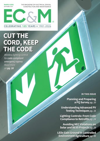
Wireless lighting control for code-compliant emergency egress
Read more on pg. 38 IN THIS ISSUE
Planning and Preparing a PQ Survey pg. 10 Understanding Advanced PV Testing Techniques pg. 16
Lighting Controls: From Code Compliance to Retrofits pg. 24
Avoiding NEC Violations on Solar and BESS Projects pg. 28
LEDs Gain Ground in Controlled Environment Agriculture pg. 49
As Sure as the Sun Comes Up
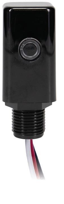
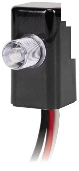
New Options to Support the Transition to LED
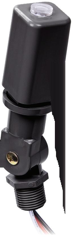
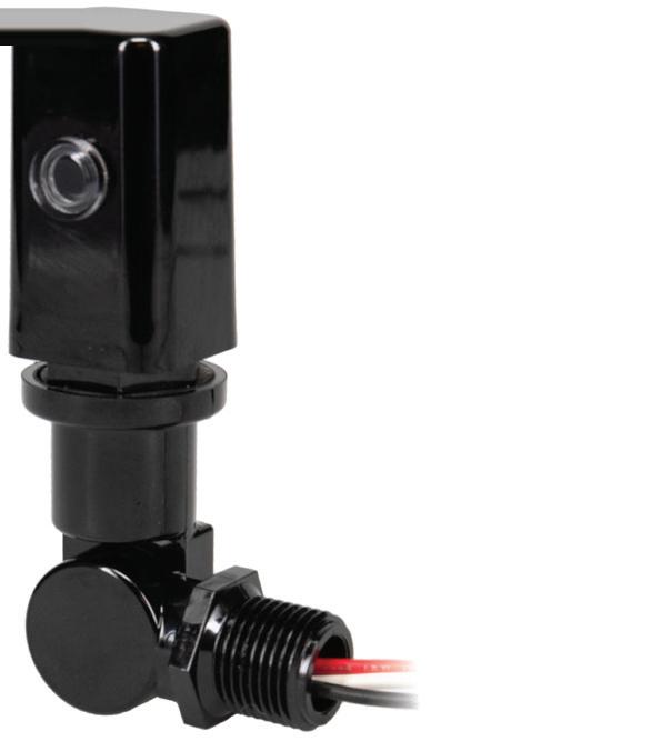
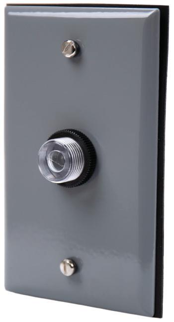
Converting traditional light fixtures to LED provides lasting energy savings and lower operating costs. However, if LED fixtures are paired with thermal photocontrols, that costsavings is quickly lost due to premature failures and unplanned maintenance needs.
Choose high-performance NIGHTFOX Electronic Photocontrols to ensure the long-term success of LED conversion projects. Our new fixed mount electronic photocontrols are designed for LED and can accommodate projects of all budgets and sizes.
Learn more today at
Because today’s performance-based codes focus on outcomes rather than wiring methods, networked lighting systems can deliver fail-safe egress illumination with streamlined installation and automated verification.
From lettuce to cannabis, LEDs are becoming a major technology in horticulture lighting. But energy efficiency isn’t the only business driver.
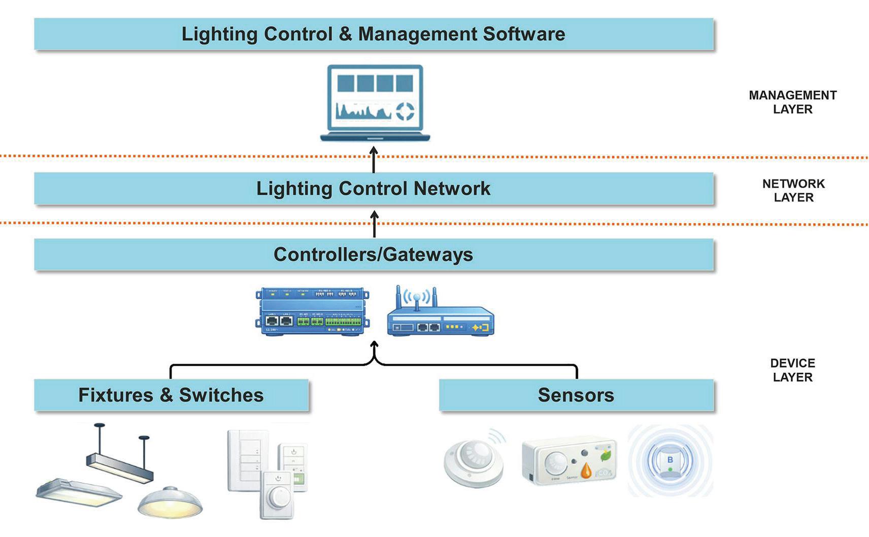
An in-depth look at how electrical professionals can design, specify, and deploy connected lighting systems as IoT-enabled platforms that deliver energy savings, operational insight, and integrated building performance
level lighting control
ECMWEB.COM
With its exclusive online content, ecmweb.com is a valuable source of industry insight for electrical professionals. Here’s a sample of what you can find on our site right now:
PLANNED NATIONAL EV CHARGING NETWORK BUILDOUT TAKES A HIT
Electric Vehicles In this Members
Only article, Tom Zind looks at how federal funding clawback could delay or doom charger installations in some states, cementing troublesome patchwork system.
ecmweb.com/55356909
ADDRESSING DISTRACTION PROBLEMS ON ELECTRICAL JOB SITES
Safety SME Mark Lamendola explains how distraction contributes to reduced work output, reduced work quality, and increased danger on the job.
ecmweb.com/55343545
MOVING VIOLATIONS VIDEO NO. 352: TROUBLE OVERHEAD
Video Russ looks at an overhead run of rigid PVC conduit. The conduit sags incredibly low and is a clear NEC violation.
ecmweb.com/55355564
Editorial
Editor-in-Chief: Ellen Parson, eparson@endeavorb2b.com
Account Manager: Steve Suarez, ssuarez@endeavorb2b.com
Production and Circulation
Art Director: David Eckhart, deckhart@endeavorb2b.com
Production Manager: Josh Troutman, jtroutman@endeavorb2b.com
Ad Services Manager: Deanna O’Byrne, dobyrne@endeavorb2b.com
User Marketing Manager: James Marinaccio, jmarinaccio@endeavorb2b.com
Endeavor Business Media, LLC
CEO: Chris Ferrell
COO: Patrick Rains
CDO: Jacquie Niemiec
CMO: Amanda Landsaw CALO: Tracy Kane VP of Content Strategy: Mike Eby
EVP Building & Construction Group: Chris Perrino
Electrical Construction & Maintenance (USPS Permit 499-790, ISSN 1082-295X print, ISSN 2771-6384 online) is published monthly by Endeavor Business Media, LLC. 201 N. Main St 5th Floor, Fort Atkinson, WI 53538. Periodicals postage paid at Fort Atkinson, WI, and additional mailing offices. POSTMASTER: Send address changes to Electrical Construction & Maintenance, PO Box 3257, Northbrook, IL 60065-3257. SUBSCRIPTIONS: Publisher reserves the right to reject non-qualified subscriptions. Subscription prices: U.S. ($68.75 year); Canada/Mexico ($ 112.50); All other countries ($162.50). All subscriptions are payable in U.S. funds. Send subscription inquiries to Electrical Construction & Maintenance, PO Box 3257, Northbrook, IL 60065-3257. Customer service can be reached toll-free at 877-382-9187 or at electricalconstmaint@omeda.com for magazine subscription assistance or questions.
Printed in the USA. Copyright 2026 Endeavor Business Media, LLC. All rights reserved. No part of this publication may be reproduced or transmitted in any form or by any means, electronic or mechanical, including photocopies, recordings, or any information storage or retrieval system without permission from the publisher. Endeavor Business Media, LLC does not assume and hereby disclaims any liability to any person or company for any loss or damage caused by errors or omissions in the material herein, regardless of whether such errors result from negligence, accident, or any other cause whatsoever. The views and opinions in the articles herein are not to be taken as official expressions of the publishers, unless so stated. The publishers do not warrant either expressly or by implication, the factual accuracy of the articles herein, nor do they so warrant any views or opinions by the authors of said articles.
Reprints: Contact reprints@endeavorb2b.com to purchase custom reprints or e-prints of articles appearing in this publication.
Photocopies: Authorization to photocopy articles for internal corporate, personal, or instructional use may be obtained from the Copyright Clearance Center (CCC) at (978) 750-8400. Obtain further information at www.copyright.com.
Archives and Microform: This magazine is available for research and retrieval of selected archived articles from leading electronic databases and online search services, including Factiva, LexisNexis, and ProQuest.
Privacy Policy: Your privacy is a priority to us. For a detailed policy statement about privacy and information dissemination practices related to Endeavor Business Media products, please visit our website at www.endeavorbusinessmedia.com.
Please Note: The designations “National Electrical Code,” “NE Code,”
Although we routinely cover lighting and control in our print issues as well as online throughout the year, we are dedicating our March issue entirely to everything lighting — a key area of interest for the EC&M audience. What does the future hold for this sector? When you look at market forecasts for smart lighting in particular, the future is undeniably bright (sorry, I couldn’t resist the pun).
According to Research and Markets, the smart lighting market, valued at $18.5 billion in 2025, is projected to grow to $43.4 billion by 2030. In its latest industry report, “U.S. Lighting Market Outlook 2025-2033: Smart Systems, Retrofit Pipelines, and the Future of Connected Illumination,” Phoenix Research expects the U.S. lighting market to expand from $28.4 billion in 2025 to approximately $41.9 billion by 2033.
Sure, the numbers vary from forecast to forecast, but I couldn’t help noticing some underlying themes coming through in the reports. Over the next decade, major market research firms that project the size or share of the smart lighting market agree that certain trends are poised to drive market growth, including: IoT and sensor integration; energy efficiency and sustainability mandates; LED advancements, declining cost, and widespread adoption of the technology; urbanization/smart cities; and a rise in smart home demand. Taken together, these trends highlight how rapidly lighting technology is evolving. As controls, sensors, and connected platforms become integral to modern building systems, lighting is shifting from a standalone product choice to a critical networked component of energy management and smart infrastructure. This issue is packed with content that explores the driving forces behind this growth. Check out the following lineup for the latest developments.
“Advances in lighting controls and energy management have made code compliance more complex, but they’ve also unlocked better options — with higher-quality emergency lighting, easier testing and maintenance, and simpler design and installation,” writes Martin Marcier, P.Eng. in the cover story, “Cut the Cord, Keep the Code: Wireless Control for Code-Compliant Emergency Egress” on page 38.
At the same time, the rise of connected lighting platforms is redefining how lighting is used within buildings — turning fixtures into data-driven infrastructure. As authors Arati Sakhalkar and Samarth Kathare of Affiliated Engineers, Inc. point out in their feature on page 52: “Connected lighting is no longer just a utility; it is becoming a dynamic, data-driven platform shaping the future of smart buildings.”
Regulatory pressure is also shaping the market, as new building performance standards require buildings to reduce energy use and emissions over time. “Lighting systems, advanced controls, commissioning, submetering, and long-term system flexibility often represent some of the most impactful and cost-effective compliance tools,” notes Shaun Taylor, Government Relations Supervisor at Lutron, in his article on building performance standards starting on page 56.
Meanwhile, LEDs continue to gain ground in new sectors such as controlled-environment agriculture, writes Freelancer Tim Kridel in his piece on page 49. “Dynamic lighting allows for ‘light recipes’ that can increase yields,” notes one source.
With adoption of luminaire-level lighting controls rising across commercial, industrial, and institutional facilities alike, electrical contractors are finding new opportunities to deliver more efficient and flexible lighting systems, as is evidenced in these two articles: “How to Ensure Smoother Luminaire Level Lighting Control Projects” written by BetterBricks on page 20 and “Lighting Controls: From Code Compliance to Retrofits” by Sean Grasby of Wesco Energy Solutions on page 24.
EC&M readers work in a multitude of vertical markets and industries that incorporate lighting design, installation, and maintenance into their daily workflow. No matter what setting or sector you look at, the message from market analysts and our subject matter experts/authors featured in this edition is clear: Lighting will continue to evolve into a connected, data-driven platform for the built environment, suggesting that the industry’s brightest days still lie ahead.
W H E R E
Safe, reliable products from a trusted brand.
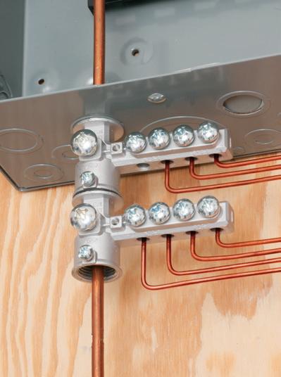
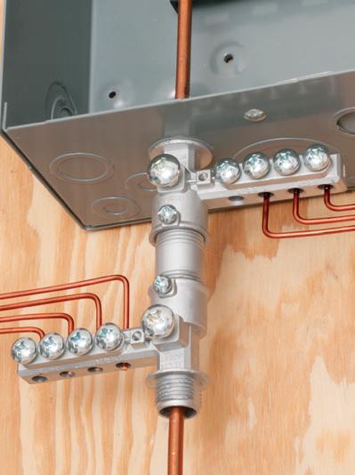
As a contractor, Safety and Efficiency are top priorities when choosing the right materials for the job Choosing copper-only conductors for residential wiring applications is a safe and efficient solution. Copper provides the best conductivity, reducing power loss and ensuring consistent and reliable power delivery. Copper-only conductors resist oxidation and maintains secure, long-lasting connections, minimizing the risk of overheating or electrical hazards.
By using copper-only conductors, you’re delivering a high-quality, reliable solution that meets all safety codes and provides your clients with peace of mind. Choose copper-only conductors for a professional, secure, and efficient electrical installation.
PQ CORNER
specific problem, such as voltage regulation, harmonics, etc., then you can limit the instruments’ triggering and recording to only those parameters. However, in many cases, a full PQ survey is required to record and trigger on voltage, current, harmonics, transients, and other parameters. Read the Sidebar below for a checklist of best practices when you’re planning and preparing a PQ survey.
INSPECTING THE SITE
A thorough inspection narrows down likely causes and often uncovers fixes you can make before monitoring.
Outside the facility. Look around the service area, and note the electrical service type, the presence of electric utility power factor capacitors, neighboring facilities that may share feeders, and nearby substations or other conditions that could create disturbances.
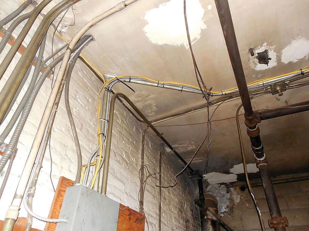
Inside the facility. Inspect for power distribution issues, including loose connections, broken or corroded wires, and hot or noisy transformers. An infrared camera may be helpful.
Follow the wiring path from the affected load back to the electrical service entrance and correct any obvious defects, such as loose connections, before monitoring begins. Pay particular attention to equipment power cords and plugs, receptacles, undercarpet wiring, electrical panelboards, electrical conduits, transformers, and
Problem
Loose connections
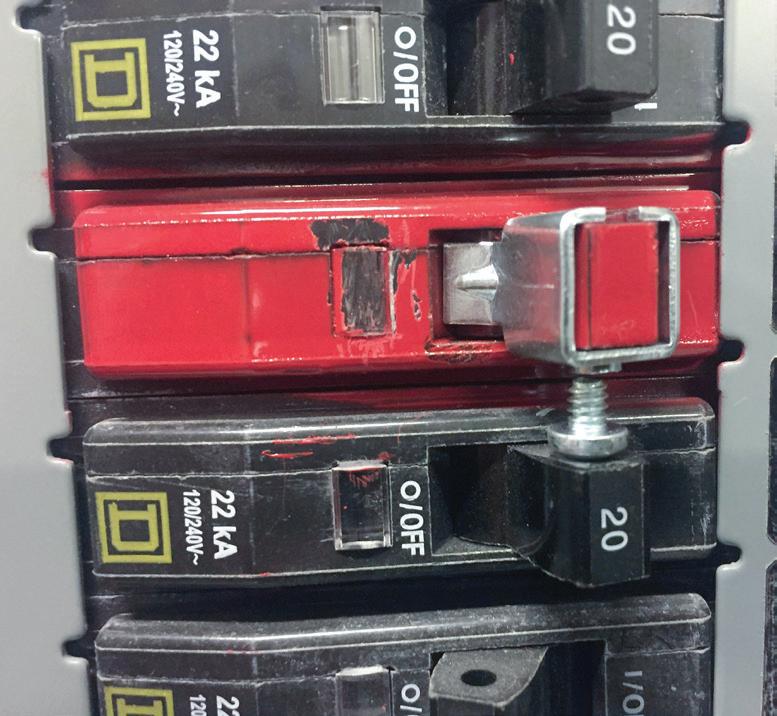
Faulty (hot) breakers
Neutral-to-ground tie
Neutral-to-ground reversal
High-impedance neutral (open) in polyphase circuit
High-impedance neutral-to-ground bond at service entrance
High-impedance open circuit grounding
Typical PQ causes and events.
the electrical service entrance. As the Table above shows, common wiring problems are a frequent cause of power quality problems.
Safety. Observe facility safety rules such as those outlined in NFPA 70E, Standard for Electrical Safety in the Workplace, comply with company and local policies, and ensure only qualified personnel perform testing/use appropriate PPE equipment.
Documentation. Record what you inspected and why, and add photos and location notes. Track any quick fixes made during the walkthrough so your monitoring plan reflects the as-found and as-left conditions.
Maintain a simple inspection log you can reference when correlating PQ events later with equipment behavior and site observations. During analysis,
Planning Checklist
• Map the timeline of problems. What, where, and when do problems occur? This will help you to identify where to monitor and for how long.
• Confirm the scope of the survey: monitor one load/section or the whole site.
• Build the site history with times, durations, symptoms, changes, and operating cycles.
• Plan your inspection path outside and inside, and list any quick fixes to complete before you monitor.
• Choose monitoring quantities and methods. Definitely include voltage and current; then add others as needed. Set thresholds, intervals, and sampling.
• Document the safety and access plan, and confirm qualified personnel will perform the work.
Effect
Transients, voltage drops
Transients, voltage drops
Ground current
Ground current
Extreme voltage fluctuation (high or low), neutral-to-ground, voltage fluctuation
Extreme voltage fluctuation (high or low), neutral-to-ground, voltage fluctuation
Neutral-to-ground voltage fluctuation
you will compare inspection records and site data with equipment event logs and performance specs, then classify and group the key events you extract.
PLAN THE MEASUREMENT APPROACH
Select your initial monitoring points based on what you know: PCC for overall health, the load, or the nearest upstream panel for local issues. Define the quantities and methods you will use. Always capture voltage and current, then add items like harmonics, flicker, and unbalance if they are relevant. Set event thresholds, logging intervals, and sampling rates to see background trends and capture disturbances as they occur.
Document the safety and access plan before you start any monitoring. Confirm personal protective equipment (PPE) needs, arc flash requirements, and permitting in line with facility and local requirements. Only qualified personnel should perform testing and maintenance work.
NEXT IN THE SERIES
Look for the final article in this series, in which we’ll cover best practices for conducting the PQ survey and taking corrective action.
Ross Ignall is the Director of Business Development and Marketing at Dranetz Technologies, a GMC Instruments company, where he has more than two decades of experience in power monitoring and analysis. He can be reached at RIgnall@ dranetz.com.
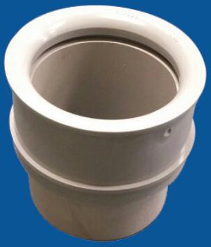
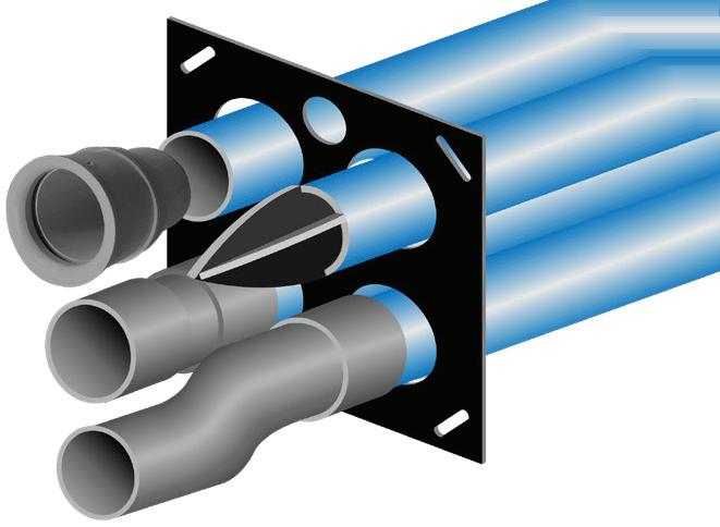
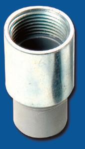
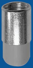
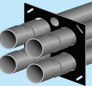
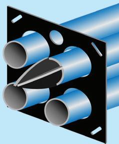
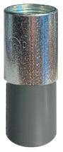
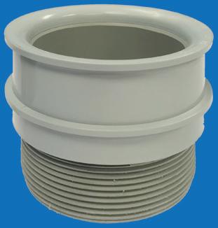
IP12 PVC Slip Transition Couplings
Reaming NOT Required
Adapters
Transition Couplings
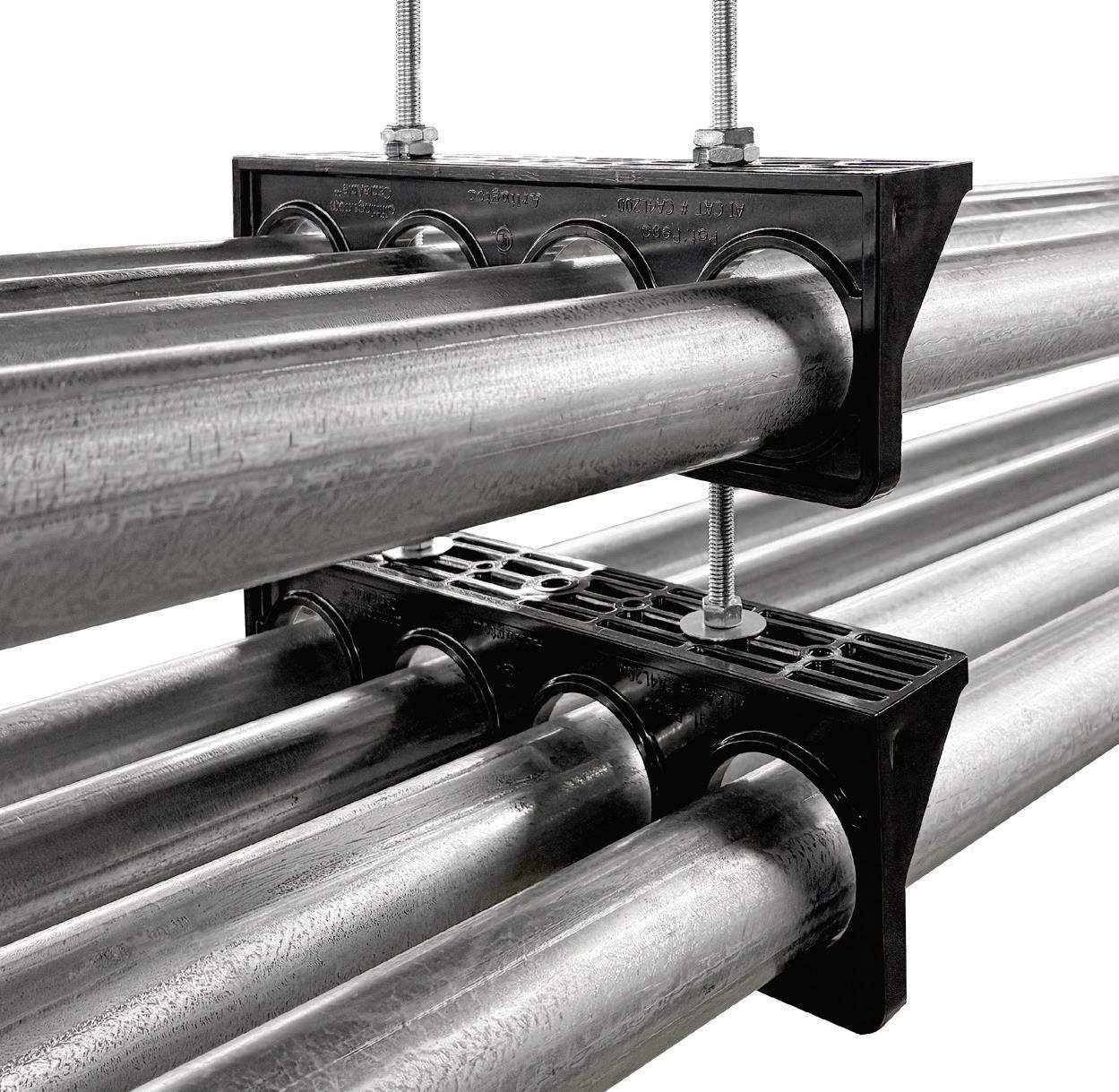
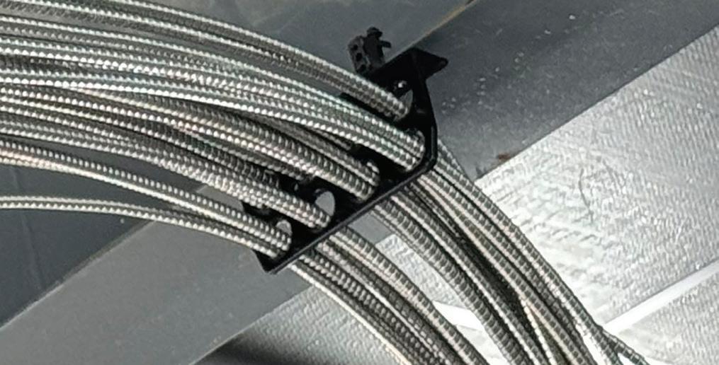
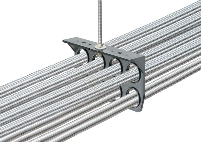
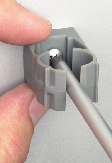
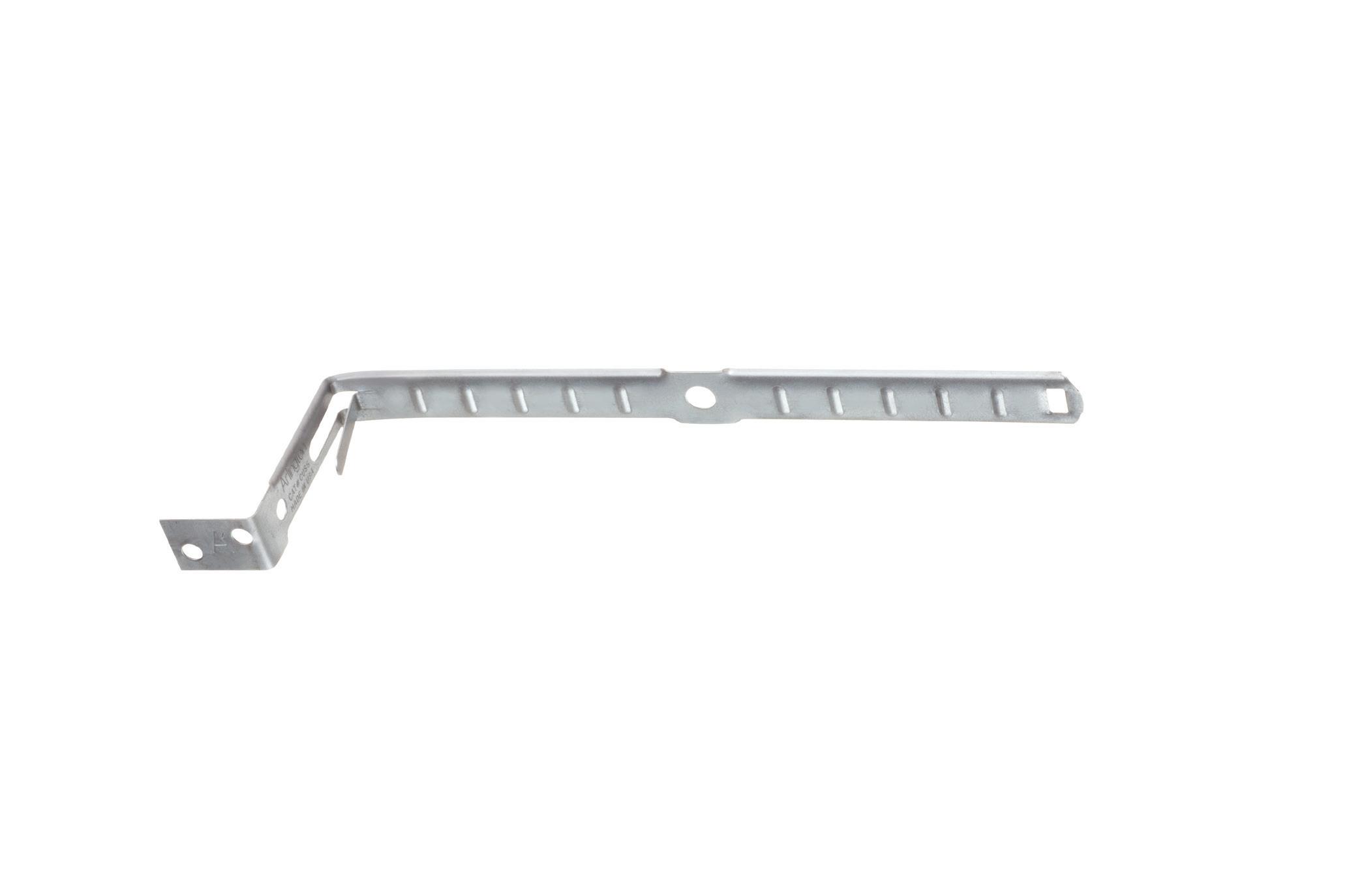
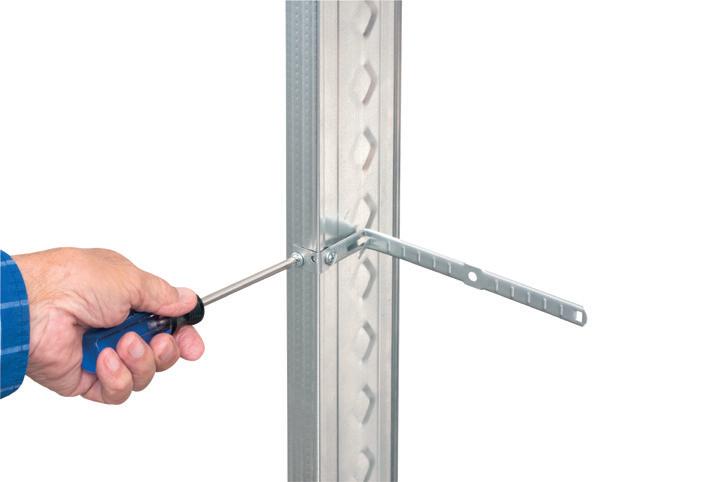
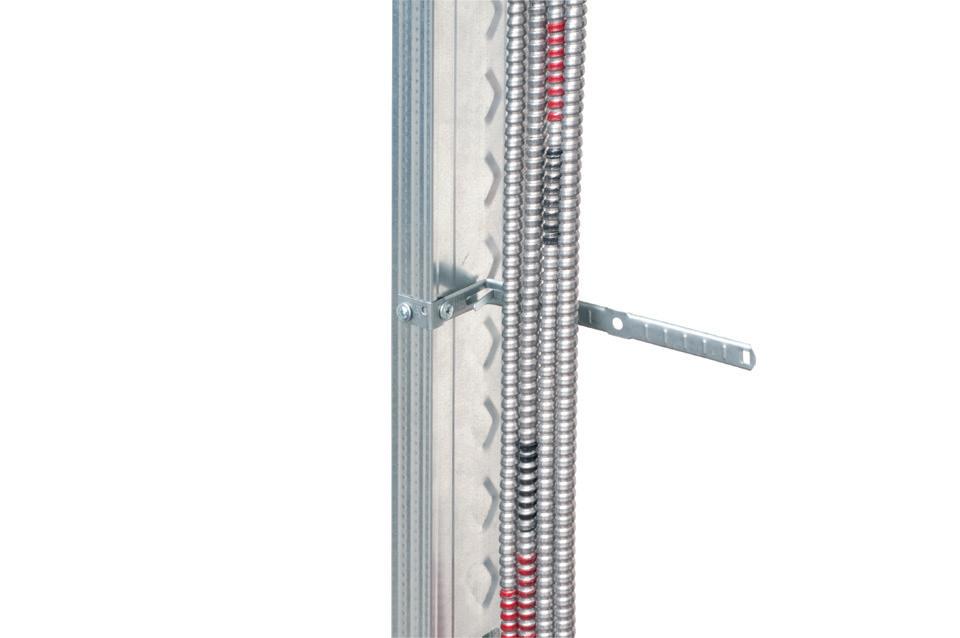
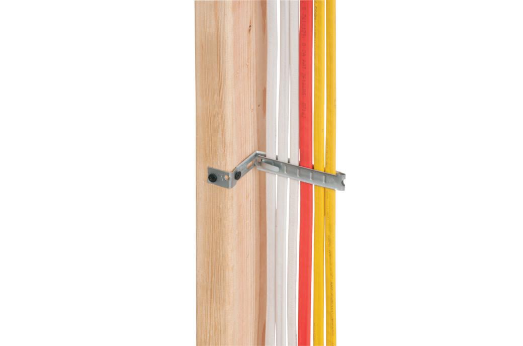
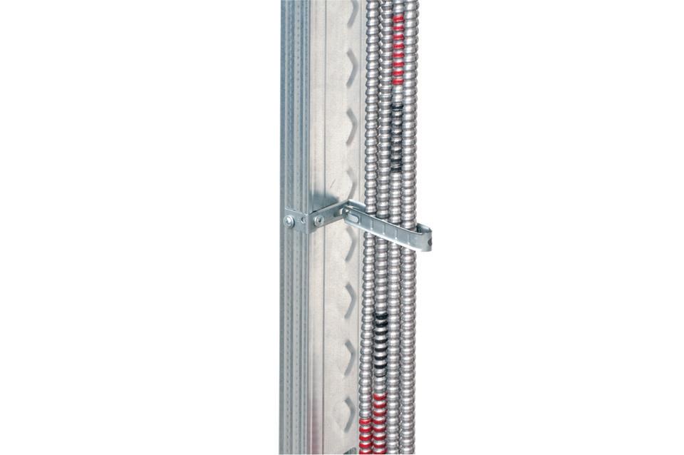
Stacking CableAble Support Brackets on Threaded Rod
• Power, data, communications, control systems
• Plenum applications per NEC 300.22(c)
• Applications with temps from -5°C (23°F) to 90°C (194°F)
• Outdoor use, in wet locations
• Lowering total installed costs
• Minimizing space required for supportand reducing ceiling congestion
WATCH THE SAVINGS STACK UP with CableAble® Support Brackets... the ONE BRACKET for reliable support of EMT or flexible metal conduit, power MC and NM cables, and low voltage cables, in commercial or residential work, with plenum or non-plenum ceilings.
Four- and eight-hole CableAble mounts horizontally or vertically to studs or unistrut. And horizontally to all thread and beam clamps. ITEM
CA8 Eight, 1-1/4" T Bracket
CA8L Eight, 1-1/4” L Bracket
CA4 Four, 1-1/4" T Bracket
CA4L Four, 1-1/4” L Bracket
All styles available in bulk 50 packs. To order, add “X” suffix to item number.
ELECTRICAL TESTING EDUCATION
Understanding Advanced PV Testing Techniques
How I-V curve testing helps optimize solar array efficiency and identify performance losses in the field
By Jason Carlson, CBS Field Services
As the world of solar energy continues to grow, testing on the acceptance and maintenance sides will inevitably grow with it. In typical installations, technicians have been asked to test only the basic electrical apparatus. This typically consists of circuit breakers, transformers, instrument transformers, relays, cables, grounding, and functional testing. Inverters are often held for the manufacturer to set up and commission as they tend to have proprietary software for their systems. At the photovoltaic (PV) array, they have been limited to verifying circuits, grounding, and possibly circuit breakers if the system is so equipped.
USE THE I-V CURVE
In truth, the arrays or panels themselves should undergo testing that uses the I-V (current-voltage) curve and basic test equipment. Plotting the I-V curve can help the engineers make changes to their model using real-world scenarios and capture maximum efficiency from the PV system.
There are many influences on a PV system that affect its output. These can be as simple as weather (clouds, smog, fog, snow, ice), environmental issues (smoke, dust, dirt, shade, reflection), and the age of the system.
By utilizing the correct test equipment, you can plot an I-V curve and examine the efficiency of the array. Ignoring other components of a PV system and focusing only on the PV
array itself, the following test equipment is recommended:
• Irradiance sensor
• DC clamp-on ammeter
• Multimeter capable of measuring direct current voltage (DCV)
• Insulation resistance meter
• Infrared camera
Note that several companies produce PV array test equipment that can increase testing efficiency by pulling output data of the array into one system to plot the I-V curve.
Electrical Testing Education articles are provided by the InterNational Electrical Testing Association (NETA), www.NETAworld.org. NETA was formed in 1972 to establish uniform testing procedures for electrical equipment and systems. Today, the association accredits electrical testing companies; certifies electrical testing technicians; publishes the ANSI/NETA Standards for Acceptance Testing, Maintenance Testing, Commissioning, and the Certification of Electrical Test Technicians; and provides training through its annual conferences (PowerTest and EPIC — Electrical Power Innovations Conference) and expansive library of educational resources.
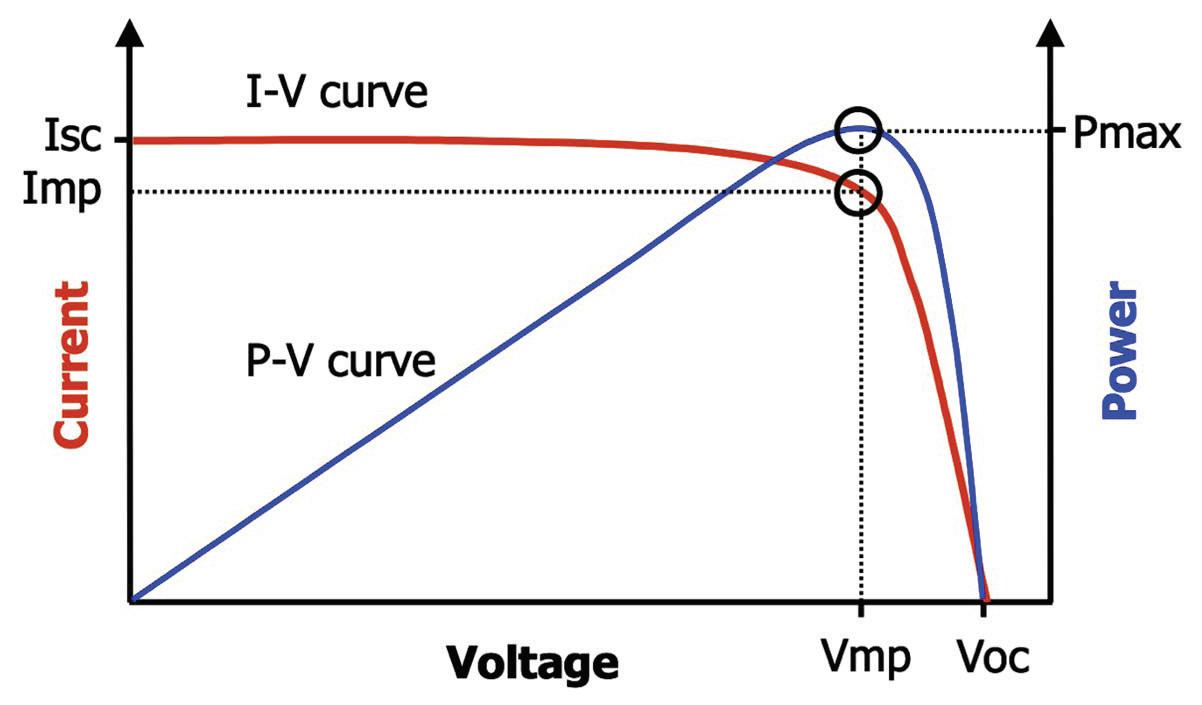
The I-V curve measures the performance of the array under the current conditions (see the Figure on page 18). This takes into account the irradiance (light), temperature, and output (voltage and current) of the array. This helps determine how to align the array, or, in instances where a tracking array follows the sun, how to best time the tracking. Several tracking systems can now adjust for the time of year, the position of the earth relative to the sun, and other inputs such as weather forecasts.
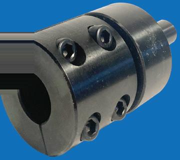
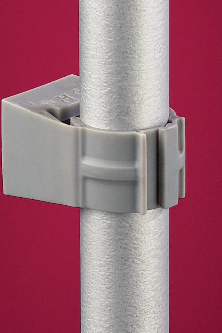
Extra-duty one-piece design
Pre-installed strut clip for faster installation on strut
corrosion-resistant QUICKLATCH® pipe hangers cost the same as a steel pipe hanger with a bolt and nut – but better. They’re faster and easier to install. And SAVE 25 seconds* per installation! • UV rated for outdoor
ELECTRICAL TESTING EDUCATION
Where:
I sc = Short-circuit current
I mp = Max power current
V mp = Max power voltage
V oc = Open circuit voltage
The maximum power point is at the knee of a normal I-V curve (where Imp and V mp intersect). This is the point at which the array generates maximum electrical power. If conditions remained constant in a perfect world, you would maintain this maximum power — but this is seldom the case. Many factors affect efficiency, even in the most complex arrays that are designed to track and maximize efficiency.
PROVE SYSTEM OPERATION AND EFFICIENCY
Along with the normal testing of the apparatus that electrical professionals are all accustomed to, you can use the test equipment listed above to plot an I-V curve and prove the operation and efficiency of the system. Looking at the I-V curve, you can also evaluate the fill factor (FF) of the PV array. FF looks at the squareness of the curve.
FF = (Imp ×Vmp)/(Isc×Voc)
FF is an important indicator of performance. Currently, PV systems cannot achieve the perfect rectangle represented by the FF because any outside interference will affect the FF. The FF will also be affected by design and module technology. The left side of the curve shows the shunt losses; the down-slope or right side of the curve shows the series losses. These losses will be combined with mismatch losses like shading or other outside influences.
I-V curves can give significant information by themselves but are greatly enhanced when utilized with a proper PV model. Think of this as performing sweep frequency response analysis (SFRA) on a transformer and comparing the results with factory results. Creating that overlay allows you to obtain the greatest amount of information.
For a PV model to have value, the following information is required:
• PV module characteristics
• Number of PV modules wired in series
• Number of modules or strings wired in parallel
• Length and gauge of wire between the modules or strings
• Irradiance in the plane of the array
• Cell temperature
ENSURE EFFICIENT OUTPUT
Many things can affect the efficiency and output of an array. Some of the more common issues include:
• Uniform or non-uniform soiling caused by dust, dirt, grime, or clouds and fog can affect the array (as discussed earlier) by blocking the irradiance. Degradation is typically a slow process based on the quality of materials used to build the panels. Over time, the sun damages the covering material on the panels, decreasing their ability to produce. We have all seen vehicles with clouded headlights due to environmental factors.
• Incorrect modules being selected for the model is rare, but it can also greatly affect the predicted model expectations
Typical I-V curve.
compared to real-world output and efficiency. Verifying that the correct modules are in use is important.
CONDITIONS DURING TESTING
It should go without saying that looking at the conditions during testing is always important for electrical testing. Making sure that PV testing is performed close to the time the model shows optimum production will yield more accurate results. Rising or setting sun conditions can vastly affect PV production.
Other issues can be as simple as improper positioning of the irradiance sensor or not considering reflection. Reflections from a variety of sources, including a window across from the array at a certain time of day or even the window on the technician’s vehicle, can greatly affect PV output. Reflections from nearby water or other objects are sometimes overlooked as well.
Temperature is very important in correctly assessing the measured curve versus the predictive model. Higher temperatures will result in a lower Voc. This could be due to improper measurement techniques including, but not limited to, taking measurements on the face of the cells versus the back of the module or a poor connection to the measurement device.
Notched I-V curves can indicate shading or, worse, a damaged PV cell. If a cell is damaged, it can become electrically isolated and mirror the effects of shading. This shows the importance of visual/mechanical inspection of all components in the system.
IN SUMMARY
As with all NETA testing, PV testing will advance as the technology advances. With the growing use of solar power, testing will have to grow with it. As systems being implemented today near the end of life, it will be important to determine the most cost-effective time to replace components rather than keeping them in service. As technology advances, the industry should see longer lifespans and greater harnessing of this endless energy source.
Jason Carlson is Vice President of CBS Field Services based out of the Pacific Northwest. He started his career in critical power, specializing in uninterruptible power systems and DC systems before joining a NETA testing firm.
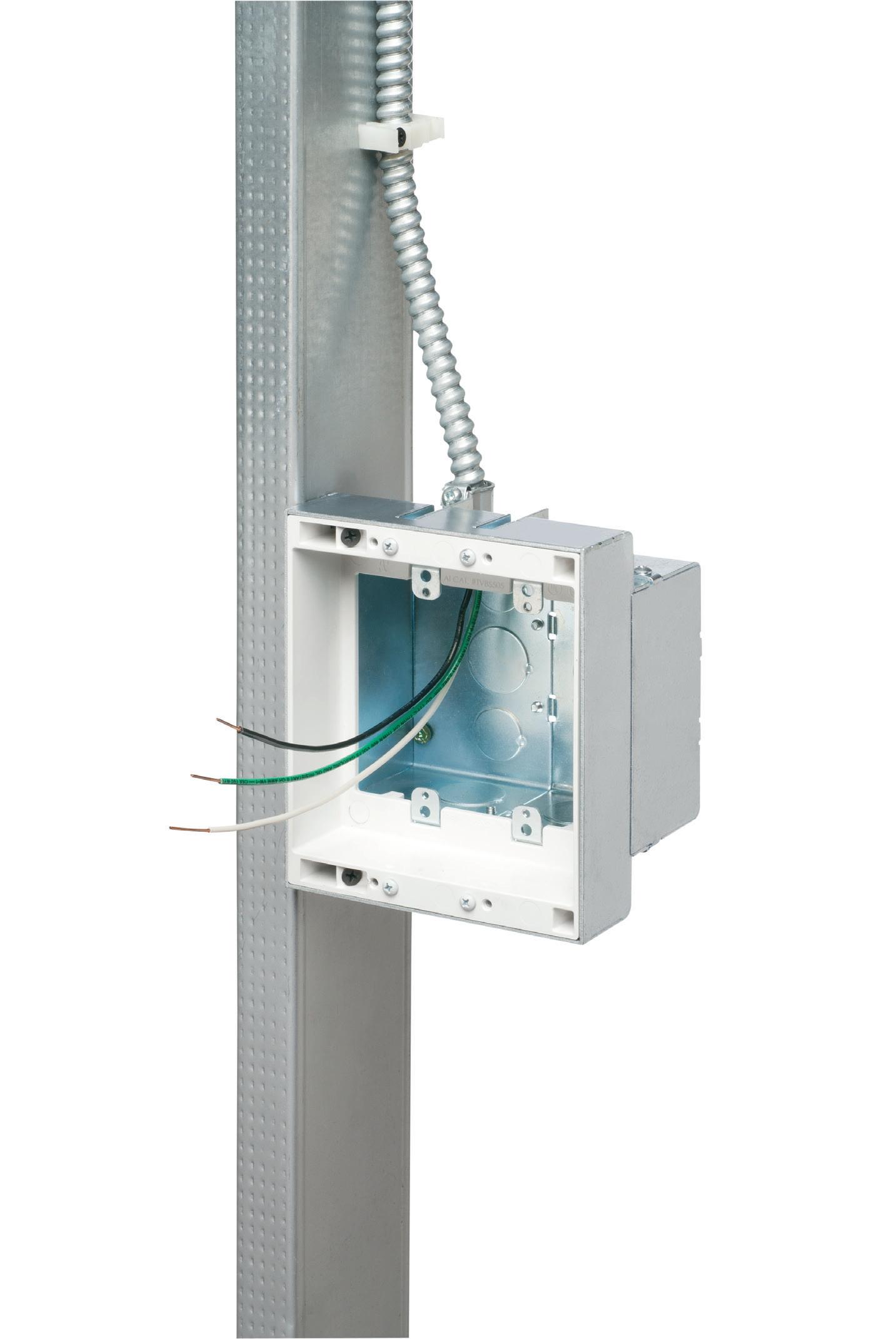
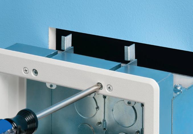
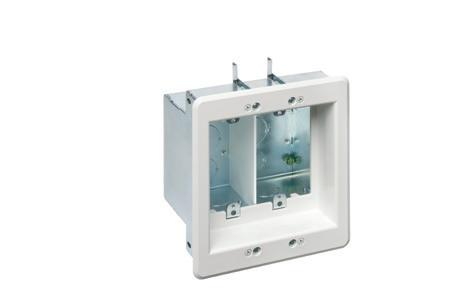
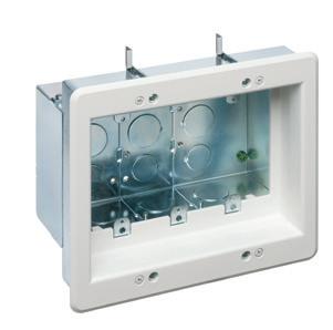
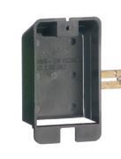
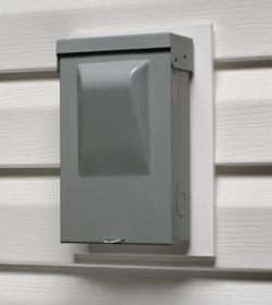
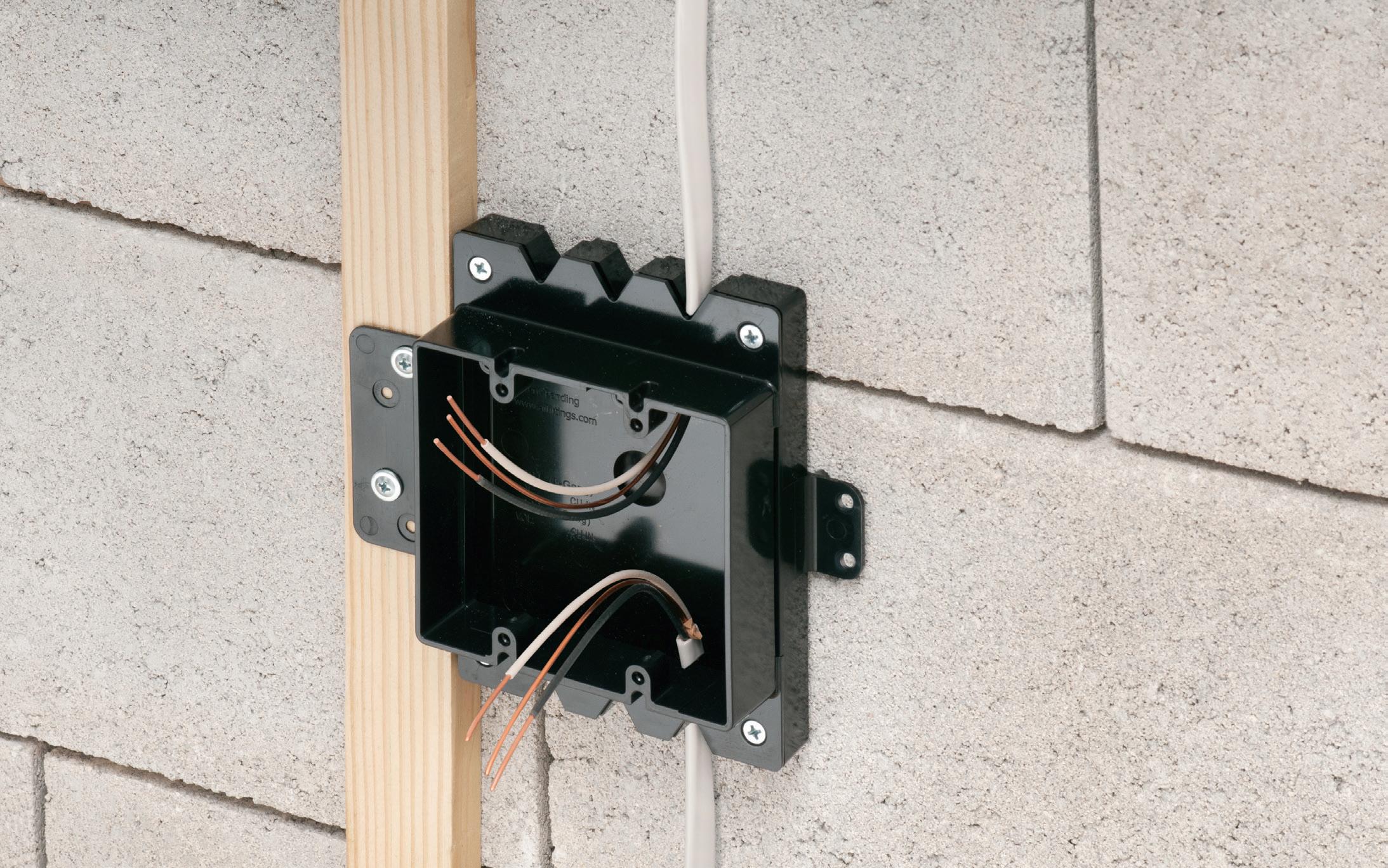
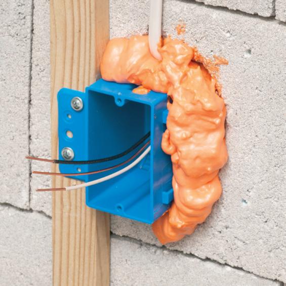
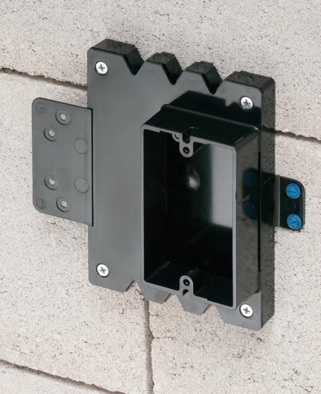
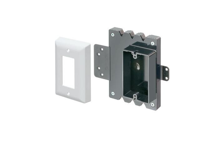
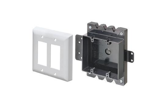
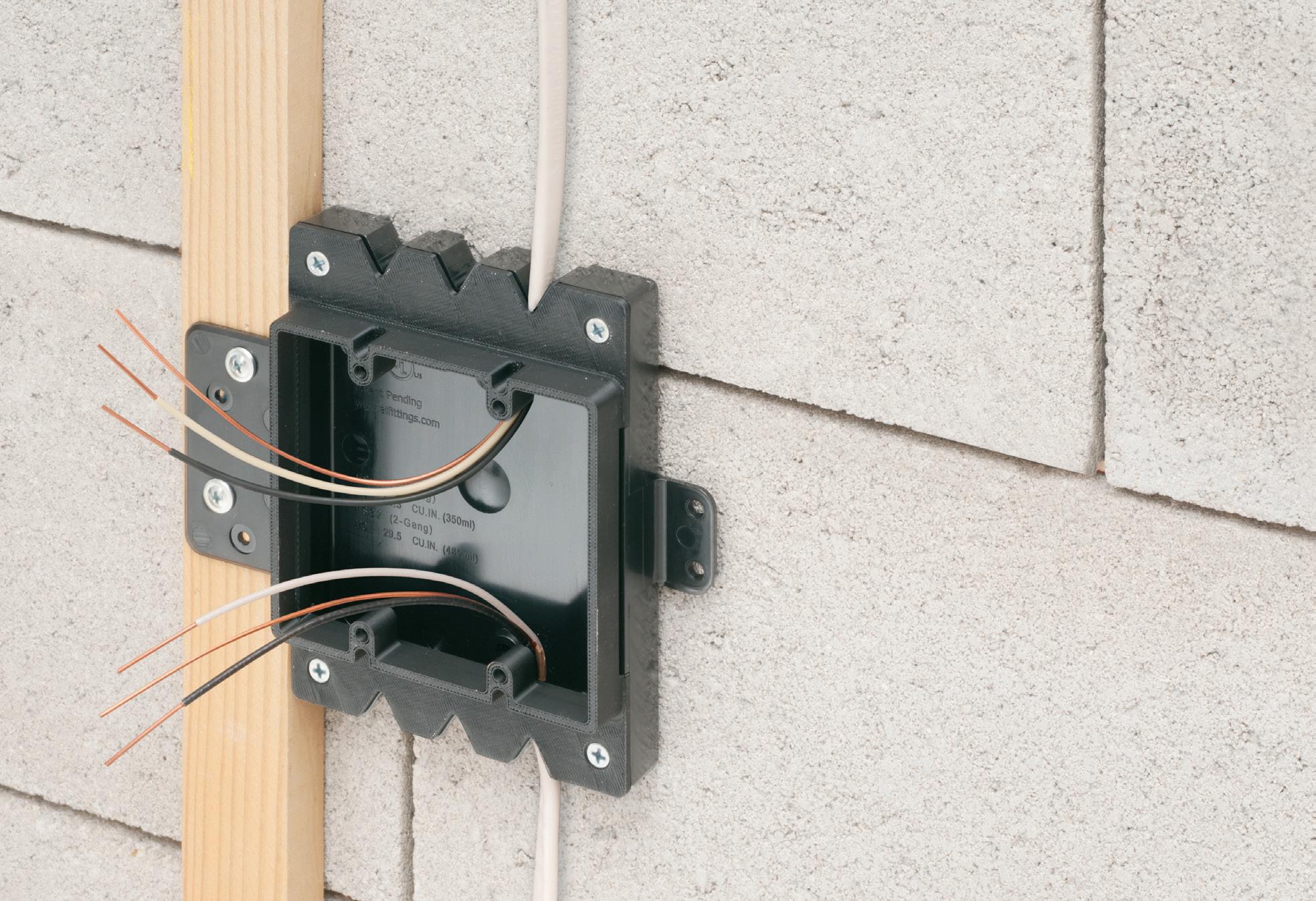
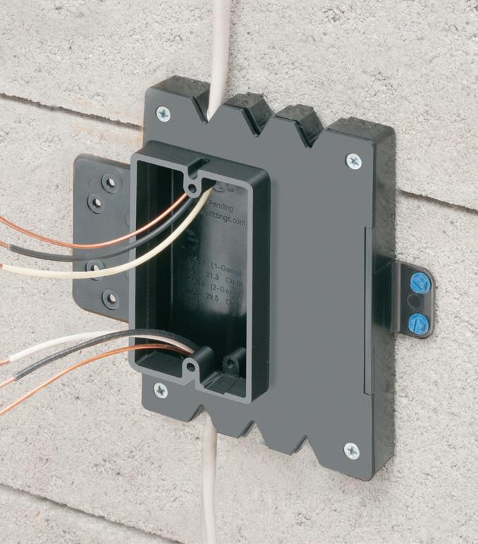
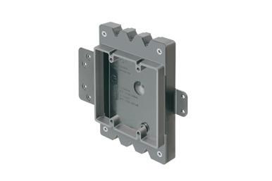
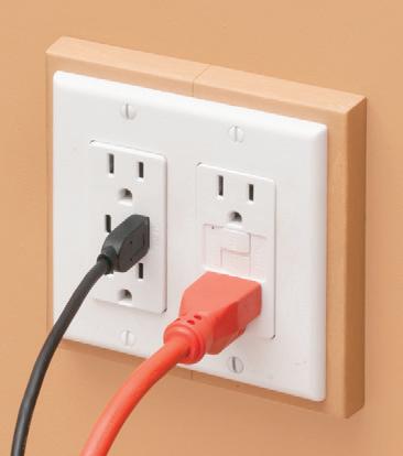
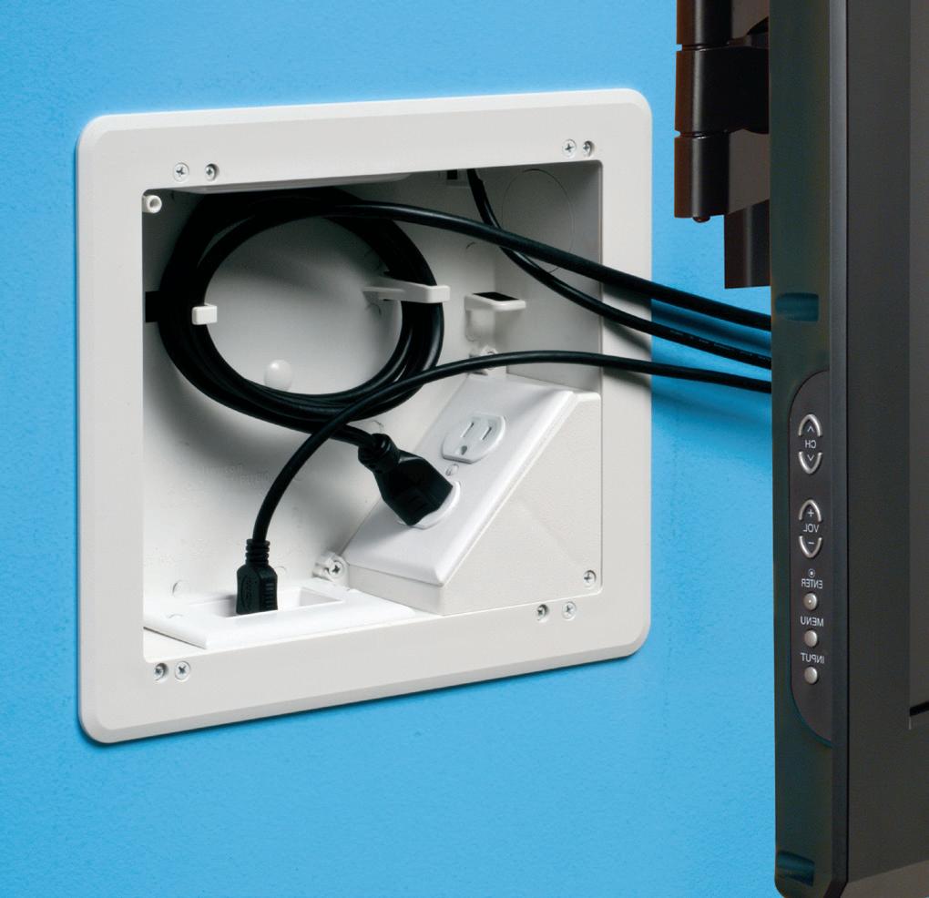
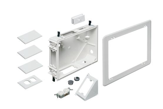
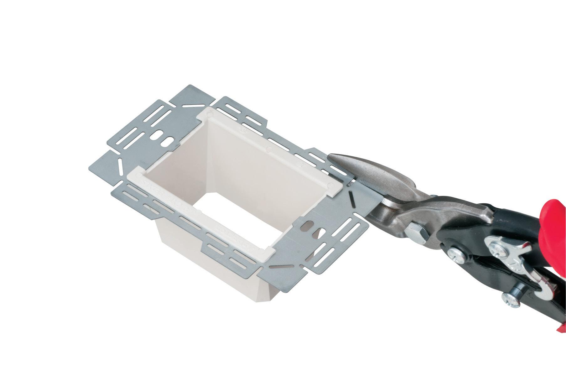
Arlington’s recessed STEEL combination power/low voltage TV BOX® is the best way to mount an LED or Hi-Def TV flush against a wall.
TV BOX provides power and/or low voltage in one or more of the openings. Plugs and connectors stay inside the box, without extending past the wall.
Designed for use in new or retrofit commercial construction where metal raceway is used, we have a STEEL TV BOX for almost any application!
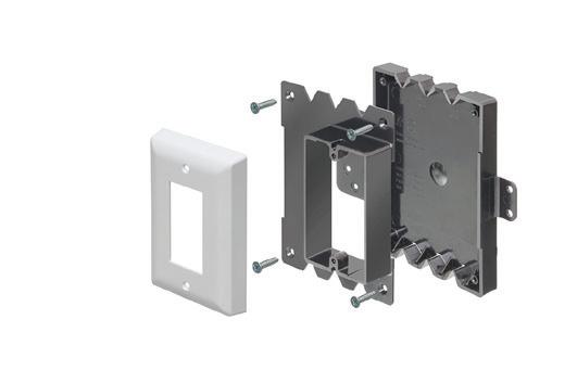
• Steel box; non-metallic paintable white trim plate
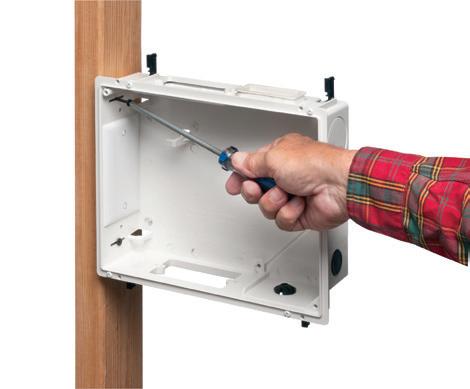
• Easy, secure installation
• Optional covers
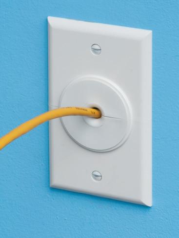
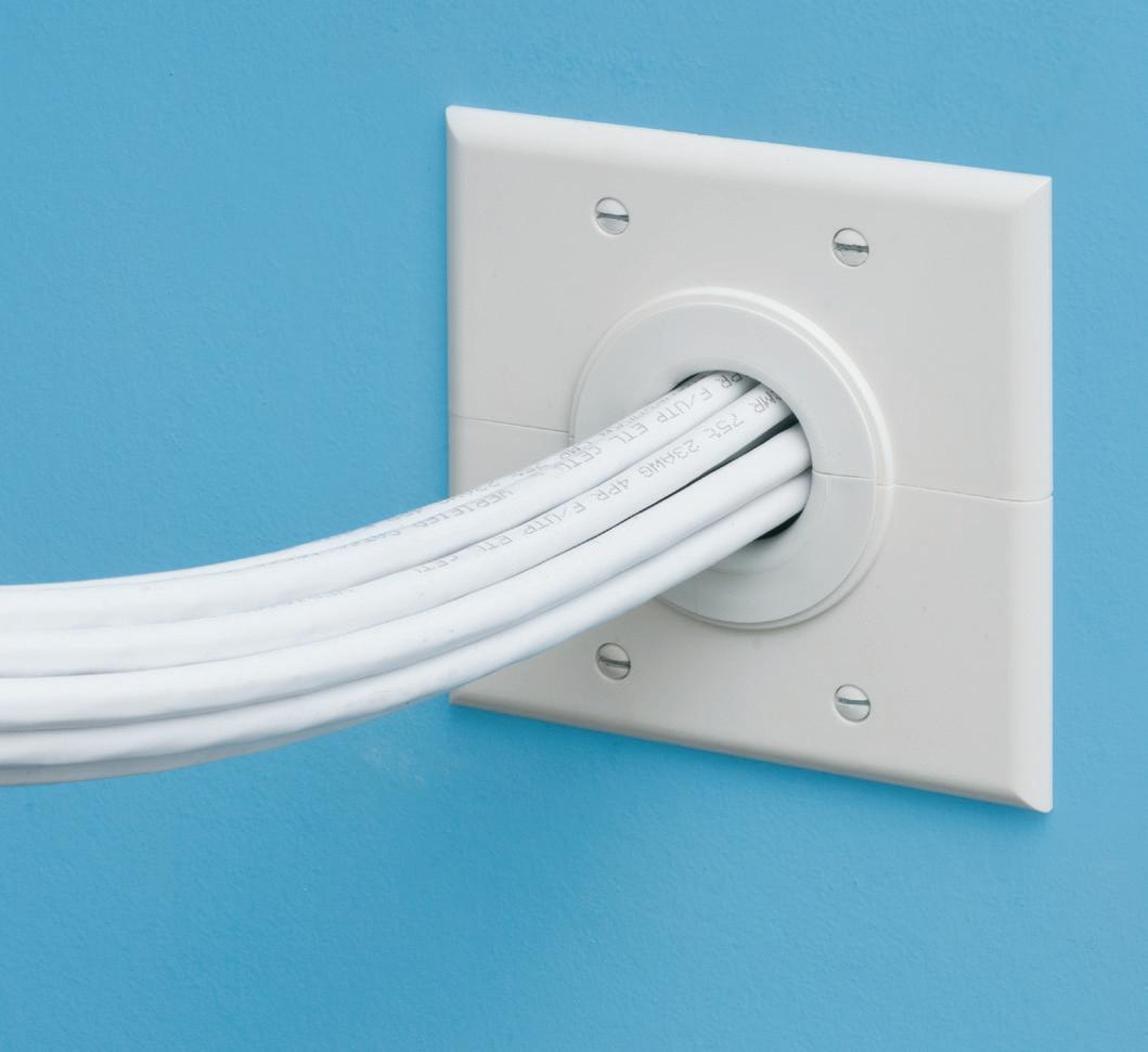
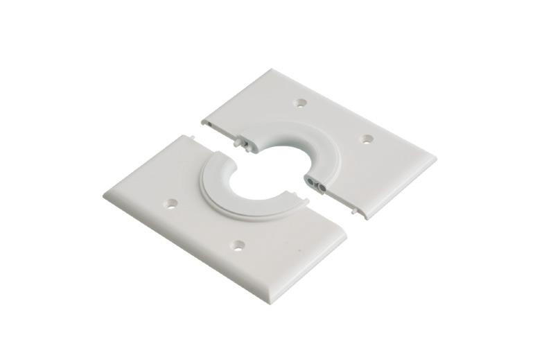
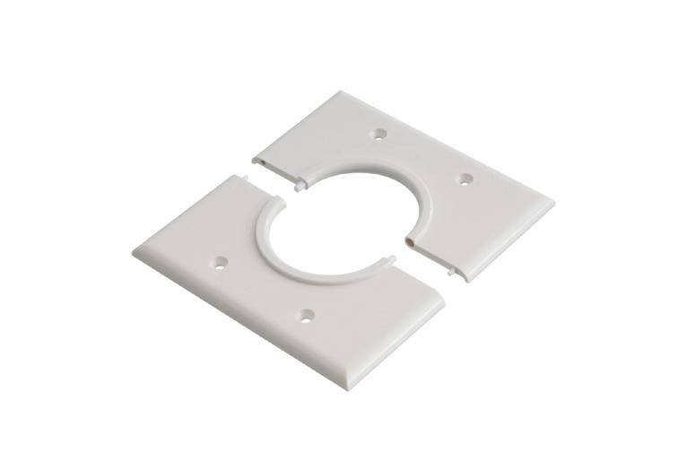
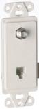
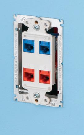
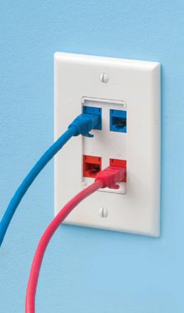
Arlington’s non-metallic Split Wall Plates provide a simple and effective way to accommodate pre-connectorized low voltage cable(s) of varying size and quantity or pre-existing low voltage cables.
Multiple split grommets are provided with our single- and two-gang wall plates for increased versatility in effectively sizing and covering the hole/opening.
Use as shipped, or with one of the supplied bushings to alter the size of the opening.
• Single-gang CESP1 w/ 1-1/2" opening, bushings for .312" • .500" • 1" openings bushings for .750" • 1.250" openings
How to Ensure Smoother Luminaire Level Lighting Control Projects
A three-step approach electrical contractors can implement to improve user experience with LLLC
Written
by BetterBricks, part of the Northwest Energy Efficiency Alliance (NEEA), a nonprofit alliance of more than 140 utilities and energy efficiency organizations
Adoption of luminaire level lighting controls (LLLC) continues to rise across commercial, industrial, and institutional facilities as more building owners and facility managers turn to wireless, networked systems that can be rezoned and reconfigured without
rewiring or climbing ladders. Many fixtures arrive pre-programmed, use standard 3-wire connections, and can be commissioned with a smartphone or tablet. Even so, project outcomes vary with the customer’s understanding of the system. As demand grows, so does the need to guide users toward a smooth experience. Implementing a simple three-step approach can ensure installers have a successful lighting upgrade and hand-off.
1. Prior to installation, discuss the sequence of operations with the
customer, so you understand what settings they want in each space.
2. Familiarize yourself with the programming needs and capabilities of the selected LLLC system before arriving on site.
3. Once the project is close to completion, walk through the system and settings with the facility manager or building owner, so they feel comfortable making lighting changes in real time.
These steps are part of a new toolkit produced by BetterBricks that focuses on helping contractors plan, install and
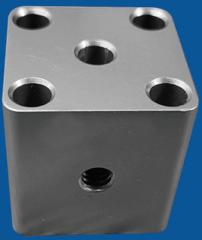
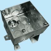
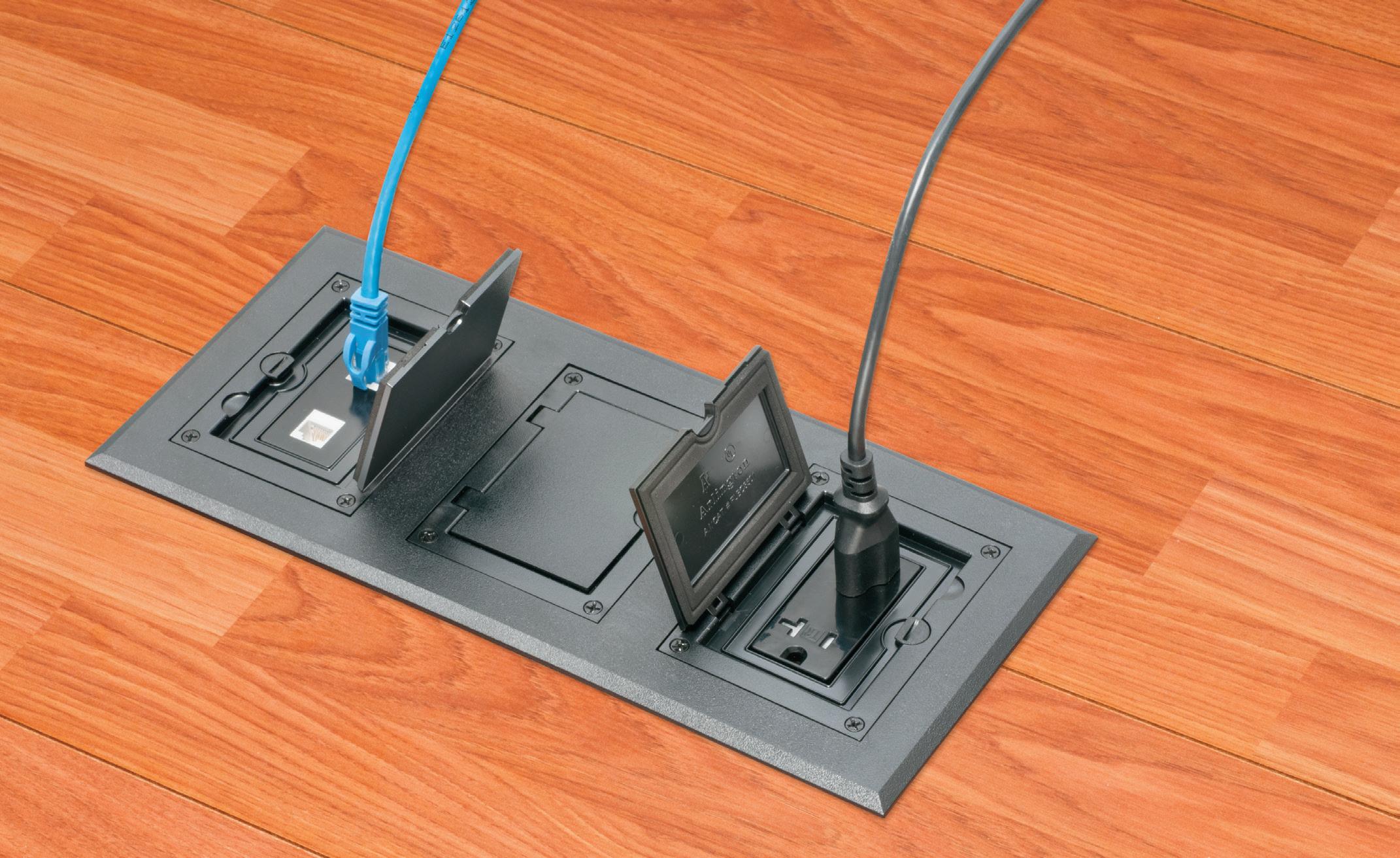
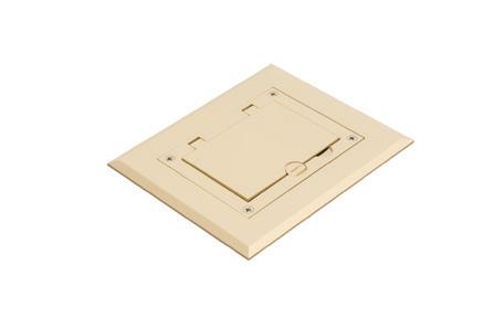
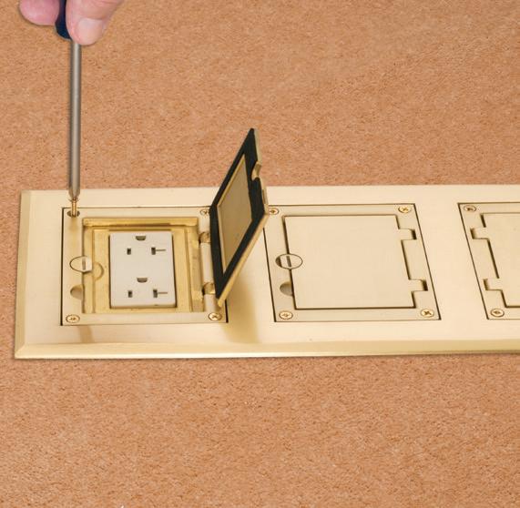
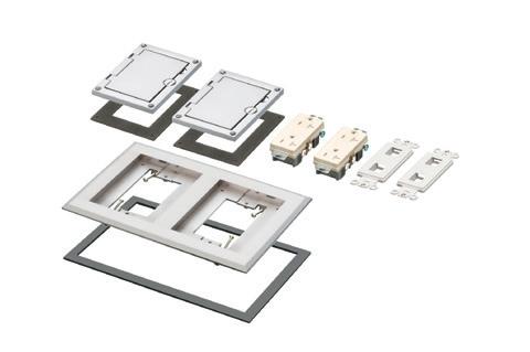
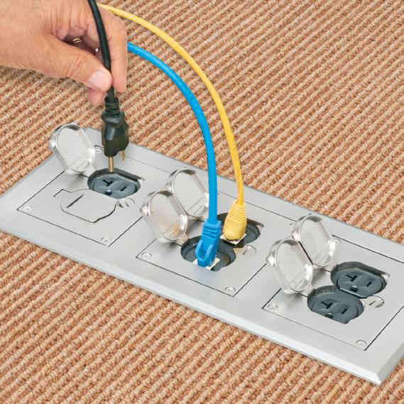
FOR NEW CONCRETE FLOORS
Side connections lock single gang FLBC8500 boxes together
Single gang box
(3) FLBC8500 boxes
(1) FLBC8530BL Black PLASTIC cover/frame kit
Lock two boxes together for a two-gang box. Add another for three-gang!
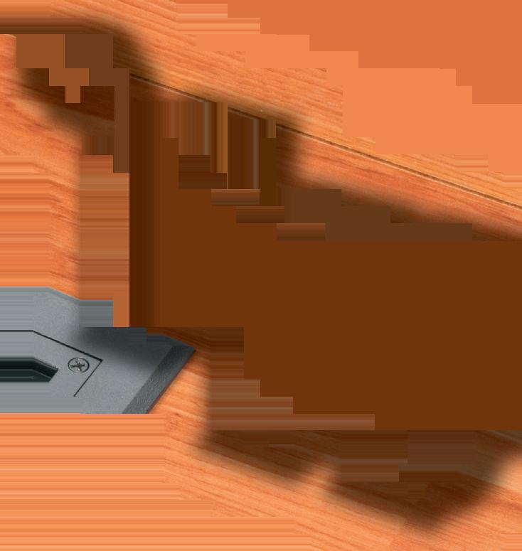
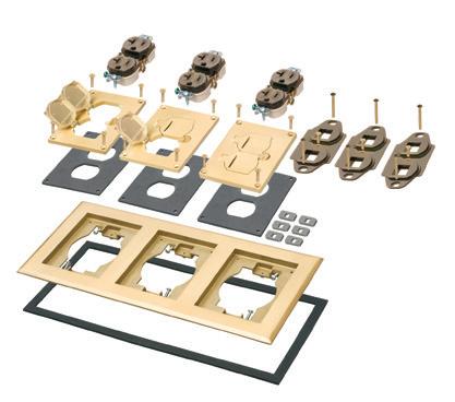
Here’s the easy way to add receptacles in a commercial concrete pour. Lock single gangable boxes together to build a two- or three-gang floor box!
Then add the UL LISTED single, two- or three-gang Cover/Frame kit, with devices included.
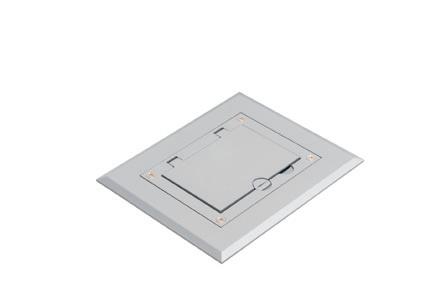
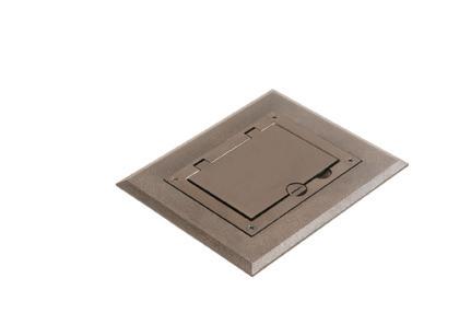
• PLASTIC in Black, Brown, Gray, Light Almond, Caramel...
• DIECAST ZINC with a Brass or Nickel finish... Furniture feed inserts also available with brass or nickel finish
• PLATED, PLASTIC or POWDER-COATED with Flip Lids
Fast, easy cover installation. Installs with hinge on either side.
FLBC8500
LIGHTING & CONTROL
hand off LLLC with fewer surprises in the field and includes an FAQ that helps answer common questions about how it works.
One frequent point of interest is energy performance and code compliance. The embedded sensors and control capabilities of LLLC can cut energy use by as much as 75% compared with standard LED fixtures, helping projects meet local and state requirements. Read more in the toolkit at https://betterbricks.com/ resources/lllc-installer-toolkit/.
These tips align with the approach used by Adam Lopez, a lighting project manager at Christenson Electric in Portland. His interest began with a curiosity about where lighting technology was headed and a commitment to understand LLLC as it evolved. As he gained experience, his projects became more seamless — a welcome shift as more customers show interest in flexible networked controls that offer fixture-byfixture granularity.
Adam Lopez, lighting project manager at Christenson Electric, shares how understanding LLLC can lead to smoother installations and stronger customer outcomes.
“From an installation standpoint, one of LLLC’s benefits is the lack of wires and complex systems, which leads to labor savings. Instead of planning out how many sensors or devices are needed, everything is built into the
fixture,” Lopez said. “We use a checklist to confirm how the customer wants their system set up and then program everything based on those preferences.”
Clear communication and preparation now define his workflow, and client follow-ups tend to focus on positive feed-
Embedded sensors
and control capabilities of LLLC can cut energy use by as much as 75% compared with standard LED fixtures.
back about how the system is performing rather than on issues that need fixing.
“What I would say to other installers is just familiarize yourself with the product, attend some trainings, talk to your suppliers,” he said. “The more knowledge you have with what you’re using, the better it’s going to be for your customers in the long run.” Find out more about this approach in the video at www. betterbricks.com/resources/betterbricksindustry-voices-adam-lopez.
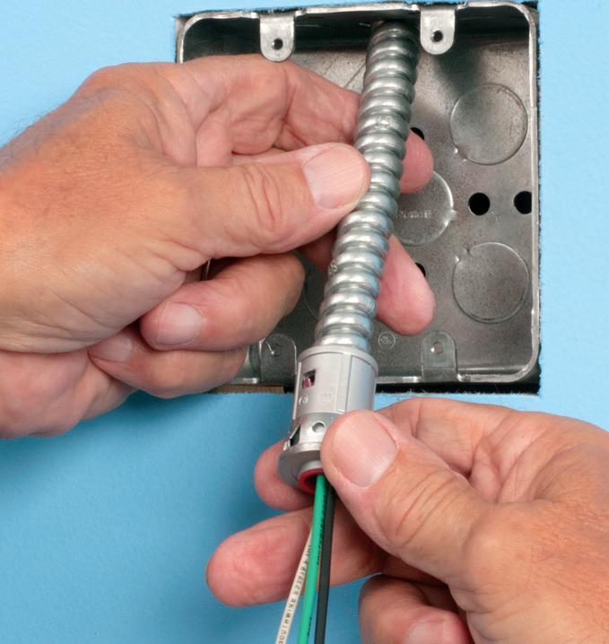
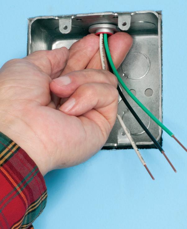
Snap connector onto installed MC cable.
Arlington’s new one-piece RETROFIT SNAP2IT® fittings are easy to use in an OLD WORK installation, and handle the widest variety of cables! They’re ideal for adding additional circuits to a load center. And you get the same labor-savings in a retrofit installation!
Easy snap-in installation - NO TOOLS. Install connector into the knockout in an existing box, pulling cable/conduit through the knockout. Slip the fitting onto the cable, then snap the assembly into the box. That’s it... a secure installation with no pullout
Widest total cable ranges 14/2 to 10/3
Widest variety of cables AC, MC, HCF, MC continuous corrugated aluminum cable, MCI-A cables (steel and aluminum), AC90,
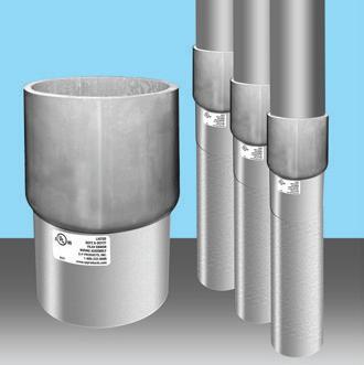
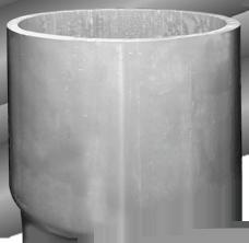
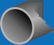
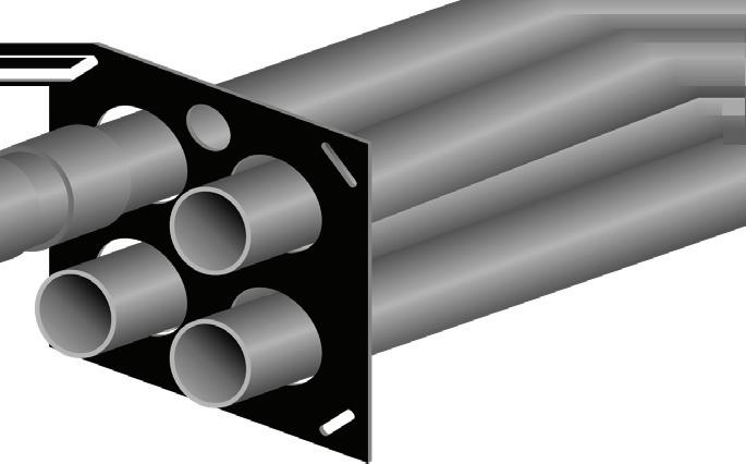
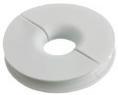
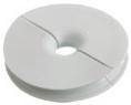
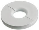
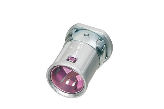
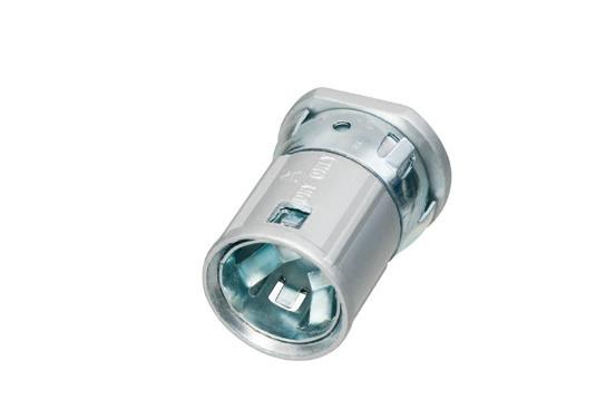
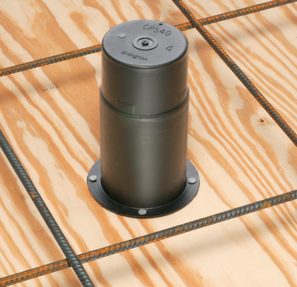
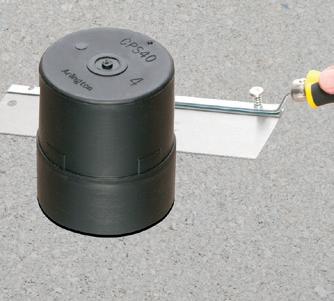
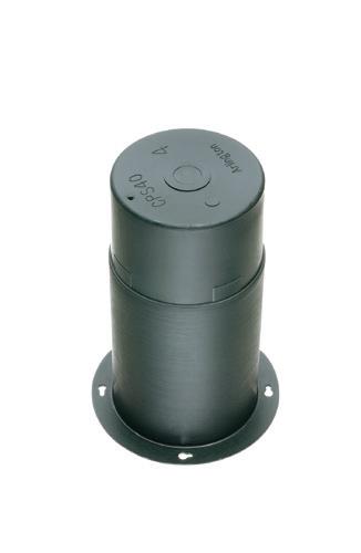
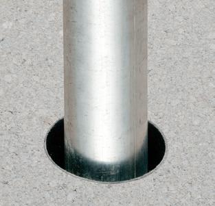
Arlington’s Concrete Pipe Sleeves are the economical way to sleeve through concrete pours in tilt-up construction WALLS – and FLOORS allowing cable and conduit to run easily from one floor to the next. No costly core drilling – No cutting holes in the form. Plus, you can position the hole prior to pouring the concrete.
• Attaches to form with nails or screws
• Stackable up to 23" h for extra deep pours
• Vents keep wet pipe sleeves from sticking together
• Multiple hole
AROUND THE CIRCUIT
Lighting Controls: From Code Compliance to Retrofits
Key considerations for electrical contractors on how to navigate evolving energy codes, plan for future-ready systems, and determine when a retrofit makes the most sense
By Sean Grasby, Wesco Energy Solutions
When we talk about lighting controls, we often limit the conversation by focusing on how lights are turned on and off, or how to optimize lighting in various spaces to enhance productivity or conserve energy. While these are important things to consider, in reality, any conversation about lighting control systems should also include several other elements as well.
When electrical contractors engage with customers about lighting controls, they should ensure that any conversations also incorporate code requirements, “future-proofing,” and whether a retrofit may be beneficial.
ENSURING LIGHTING CONTROLS MEET CODE REQUIREMENTS
As energy codes become more stringent, contractors now need to collaborate with lighting designers, architects, and engineers to not only ensure the lighting design and performance fit the specific needs, but also to comply with industry codes. Clearly, this is no small task — in many cases, a trusted distribution part ner can bring in the right expertise or handle much of the administrative burden on the contractor’s behalf.
Before starting the lighting design process and matching them to enduser preferences, electrical contractors need to make sure they understand the code requirements, including ASHRAE 90.1, IECC, NFPA 101, and any other local requirements.
• ASHRAE 90.1 is the energy standard that establishes minimum requirements for energy-efficiency designs for buildings. If a lighting design includes controls like daylight harvesting systems, occupancy sensors or programmable timeclocks, contractors need to ensure that ASHRAE requirements are met.
• The International Energy Conservation Code (IECC) is an alternate energy code model. As it relates to lighting, the 2024 IECC has a primary goal of minimizing unnecessary energy usage. At a high level, it recommends utilizing occupancy sensors, dimmers, time-switches, or other automatic shutoff controls to enhance overall energy efficiency. While IECC does allow the option to use either IECC or ASHRAE
90.1 for building projects, it’s important to note that all requirements from the chosen standard must be followed.
• NFPA 101 covers different elements of building safety regarding emergency lighting. In particular, it sets requirements for illumination levels, duration, testing, maintenance, and operation when normal power is lost.
• Local codes may also come into play. It’s important to have a trusted partner who is an expert in local lighting codes to ensure that any lighting designs are fully compliant.
FUTURE-PROOFING WITH LIGHTING
Beyond the code requirement considerations, relying on robust, code-compliant
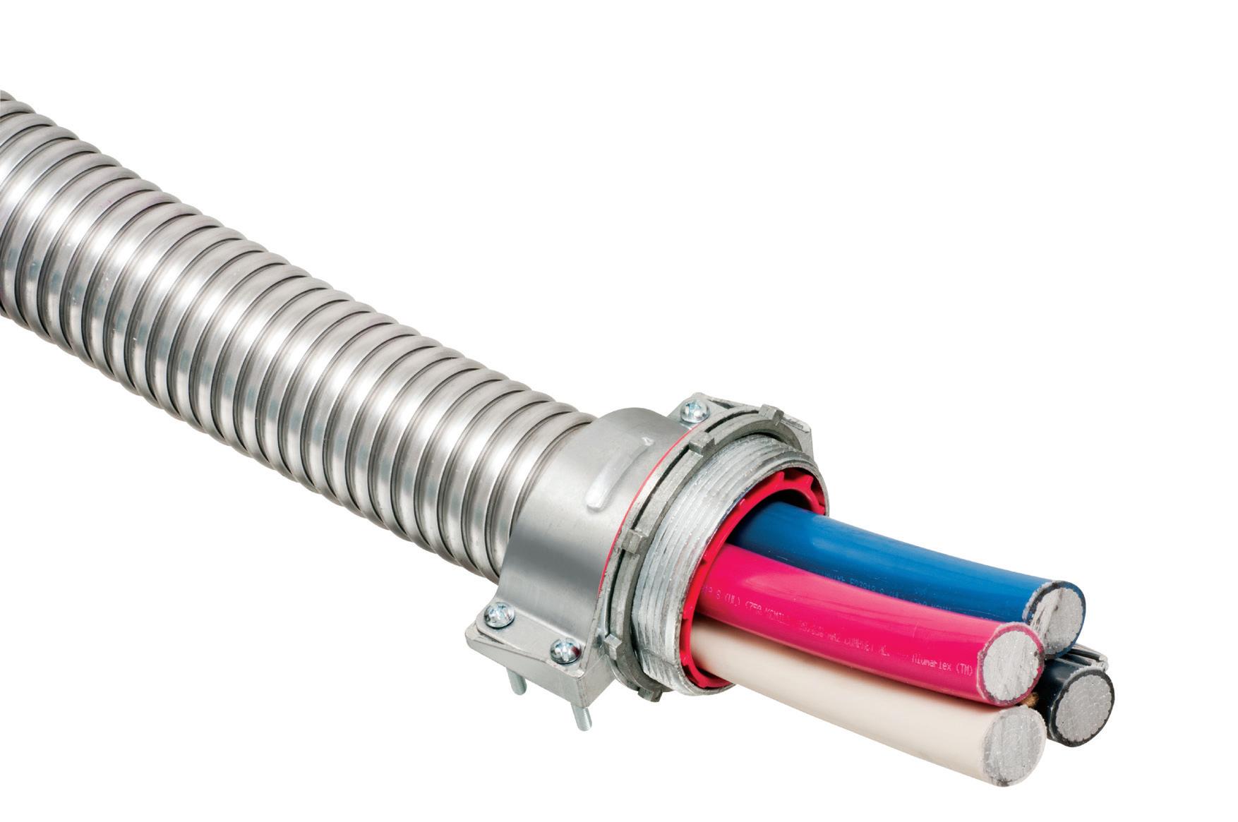
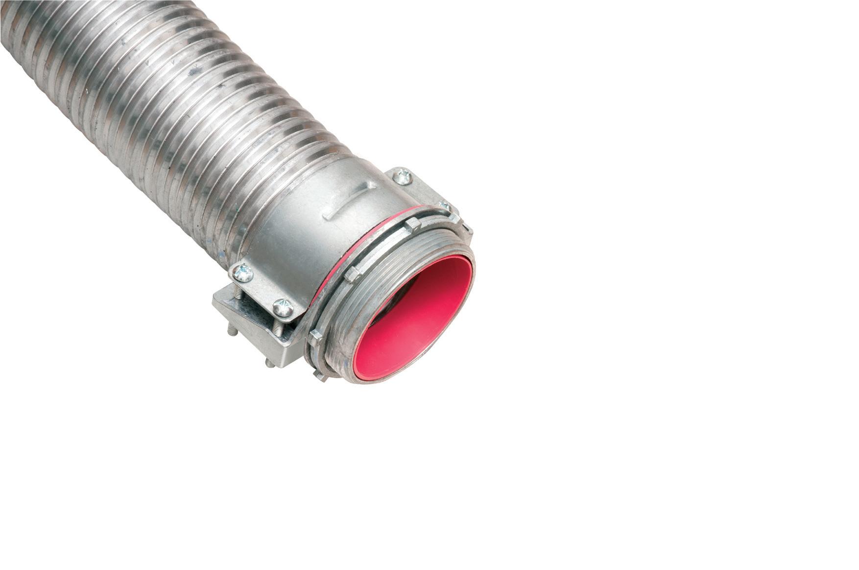
MC CABLE FITTINGS
ONE FITTING FITS MULTIPLE CABLE/CONDUIT TYPES & SIZES
* Aluminum & Steel Flexible Metal Conduits
ONE trade size fits SEVERAL cable types and sizes, plus flexible metal conduit for super convenience and cost-savings! Reduces inventory and material handling too.
This weekly e-newsletter offers subscribers a unique and inside view into the most important trends, technologies, and developments taking place within the electrical industry.
Topics covered include:
• EC&M videos & podcasts
• Market forecasts and analysis
• Code Quiz of the Week
• Online-only feature articles
• Late-breaking industry news
Subscribe Today
See all of our EC&M e-newsletters at www.ecmweb.com
systems is integral to future proofing a building as well. This helps ensure that the lighting controls put in today aren’t going to be obsolete in a few years.
Having a system in place that can accommodate future upgrades and support integrations with other systems like HVAC and building management systems (BMS) can help customers save on energy usage and streamline overall efficiency.
For example, lighting fixtures and systems with integrated controls, like luminaire level lighting control (LLLC), allow for more control over lighting output and reduced energy consumption as they optimize energy use at the luminaire level. They are also equipped with sensors and can integrate with smart technology, allowing for real-time adjustments based on environmental conditions and user preference.
THE REASON TO RETROFIT
In some cases, before advanced lighting controls become an option, a retrofit will first be required to upgrade to the most current technology, setting the project up for long-term success.
Retrofits are generally quicker and more cost-effective than new construction, especially when energy incentives are considered, which can help offset the costs with faster ROI. With retrofits, contractors also don’t typically need to work on the main structural aspects of the building, which can introduce a number of unexpected elements to a project.
While the scope of retrofits can vary project to project, there are a number of options — from retrofit kits that fit into your existing troffers, to new replacement fixtures that have new warranties, the best optics and can leverage your existing wiring — that can help contractors more quickly execute a job and minimize overall disruption to the building tenants.
For projects that implement LED lighting and controls as part of their retrofit, customers often expect to see a significant reduction in electricity bills, but the actual amount can vary considerably. For example, the amount of energy saved by moving from older LEDs to new LEDs typically isn’t significant, but can have secondary benefits such as
better lighting, longer life, lower maintenance costs, greater insight into energy usage, and easier integration into HVAC and BMS systems.
FINDING THE RIGHT PARTNER FOR LIGHTING SUCCESS
Clearly, there’s more to lighting controls than simply turning fixtures on and off. Contractors need to ensure they understand the relevant codes and standards, including local ones. The right control systems can help customers future-proof
Retrofits are generally quicker and more costeffective than new construction, especially when energy incentives are considered.
their buildings, potentially expanding the benefits beyond energy savings. And, in many cases, contractors may need to perform a retrofit before they can install the most modern controls.
While their function seems simple, lighting control systems impact the bottom line and can enhance project outcomes, but contractors may need help maximizing the benefits for their customers. Having a trusted partner on-hand can help ensure that you not only have access to top-tier lighting control products and solutions, but also expertise that can help you navigate code requirements and other key considerations.
Sean Grasby is a transformative leader with more than 20 years of experience driving business growth and strategic innovation across diverse industries, currently serving as the Senior Vice President & GM, US Construction and Wesco Energy Solutions.
•
•
Avoiding Common NEC Violations on Solar PV and BESS Projects
A focused review of key Code sections, grounding and circuit sizing requirements, and fire safety best practices to help electrical design engineers and contractors prevent costly compliance mistakes in solar and energy storage installations
By Josh Bristow and Matthew Smith, CDM Smith
With solar photovoltaic (PV) and battery energy storage systems (BESSs) becoming increasingly common in today’s electrical infrastructure, ensuring compliance with NFPA 70, the National Electrical Code (NEC), remains a critical priority for designers, contractors, and inspectors.
This article highlights and offers preventive guidance for common NEC violations. It covers Sec. 690.7 and Sec. 690.8 for maximum circuit voltage and current, Sec. 690.43 for grounding and bonding of solar array equipment, and makes distinctions between Art. 480 and Art. 706 as they apply to stationary standby batteries versus energy storage systems. This article also outlines best practices for fire hazard mitigation, ventilation, and ongoing maintenance of BESS installations — practices that reduce risk, improve reliability, and build client confidence.
SOLAR PV SYSTEMS
Photovoltaic (PV) systems are becoming a more common component of both smallscale and electric utility power generation assets; therefore, safe installation and compliance with the NEC are critical to ensuring reliable and long-lasting performance. Article 690 addresses conductors, overcurrent protection, disconnecting
means, grounding, bonding, and labeling for PV systems. A PV system comprises a series of components that work together to produce usable electricity from sunlight. The PV modules convert sunlight into DC power, conductors in raceways carry that current to inverters, and the inverters create usable AC power for distribution. Overcurrent protection, disconnects, and grounding equipment are then applied to safeguard both people and equipment. Each component must be properly sized and installed in accordance with the tables and calculations provided in Art. 690 (Photo 1).
In PV system design, the calculations for circuit voltage and current must be precise and ensure both safety and compliance with the NEC. Section 690.7 and Sec. 690.8 address these requirements and establish a clear method for sizing equipment, conductors, and protective devices, thereby accounting for environmental and operating conditions applicable to each unique installation. Section 609.7 outlines requirements for determining the maximum voltage in PV source and output circuits. Section 690.7(A) outlines the process for determining the maximum circuit
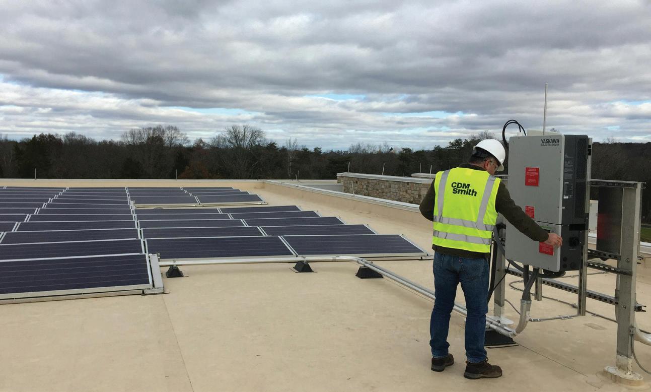
Photo 1. Rooftop-mounted solar PV array.
SMART ENERGY
Table 250.122: Minimum Size Equipment Grounding Conductors for Grounding Raceway and Equipment
Rating or Setting of
2,000 2,500 3,000
Table 250.122 from the 2023 edition of the NEC.
voltage for the system — calculating the open-circuit voltages of the modules in series. Refer to Table 670.7(A) to account for the lowest ambient temperature for the installation; this provides calculated correction factors because the PV modules will produce higher voltages under cooler temperatures.
Information about a location’s historical weather and temperature can be obtained through the National Oceanic and Atmospheric Administration (NOAA). Using NOAA’s data, an engineer can determine the lowest temperature that an installation is likely to experience and, thereby, apply an accurate correction factor. Applying the correction factor to the series sum determines the highest voltage, within reason, that the system may produce. After this value has been obtained, one must ensure all equipment — including disconnects, overcurrent protection, inverters, and conductors — is rated to withstand the maximum expected voltages.
Furthermore, Sec. 690.7 limits the PV system’s maximum voltage, depending on the type of installation (e.g., a
maximum of 600V for dwelling installations, 1,000V for non-dwelling, and up to 1,500V for utility-scale systems). These limitations ensure the components are within their design ratings, thus preventing insulation breakdown, arcing, or other failures induced by overvoltage incidents.
Section 690.8 provides the framework for determining the circuit currents of the PV system; doing so ensures proper conductor and overcurrent protection. Section 690.8(A) requires the maximum circuit current to be calculated with the rated short-circuit current (Isc) of the modules. That number is then multiplied by 125% to account for irradiance and operating conditions. For the PV source circuit (point at which the PV module connects to the protection device), this value is the sum of the paralleled modules’ I sc ratings entire PV output. Section 690.8(B)(1) then requires that both conductors and overcurrent protection devices be sized to at least 125% of these maximum currents, effectively applying a 156% factor between module I sc and conductor ampacity. Inverter output
circuits are sized differently based on the name plates’ continuous output; also, systems with multiple inverters or storage must coordinate with Art. 705. These requirements ensure that wiring and protection are not undersized, thus reducing the risk of overheating or fire during continuous maximum exposure.
In solar PV installations, improper grounding of racking, module frames, and associated equipment remains one of the most frequent Code violations. Section 690.43 requires exposed metal parts of PV module frames, electrical equipment, and conductor enclosures to be effectively grounded and bonded (in accordance with Sec. 250.134 or Sec. 250.136, regardless of voltage) to ensure a continuous low-impedance fault current path. In the field, however, equipment grounding conductors (EGCs) are often undersized or omitted, and continuity testing between modules is sometimes skipped during commissioning. These oversights not only violate Code requirements but also create serious safety hazards by increasing the risk of shock or fire. To reinforce proper sizing of EGCs, Sec. 690.45 further requires EGCs to be sized in accordance with Sec. 250.122 and Table 250.122. When a protective device does not exist within the circuit, Table 250.122 (above) may still be applied using an assumed overcurrent device rating, as permitted by Sec. 690.9(B), to ensure proper conductor sizing.
BESS
BESS use continues to grow alongside solar PV, and safe integration into electrical infrastructure has become a priority within the NEC and across industry practices. A BESS is an integrated system composed of battery modules, a power conversion system (PCS), thermal management, safety controls, and more, all working together to store energy and distribute it to the electrical system when needed. Importantly, a BESS should not be confused with what is traditionally thought of as a stationary standby battery; rather, it is a coordinated system of electrical, electrochemical, and mechanical components designed for large-scale energy storage and delivery.
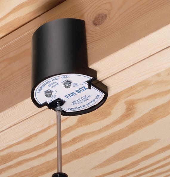
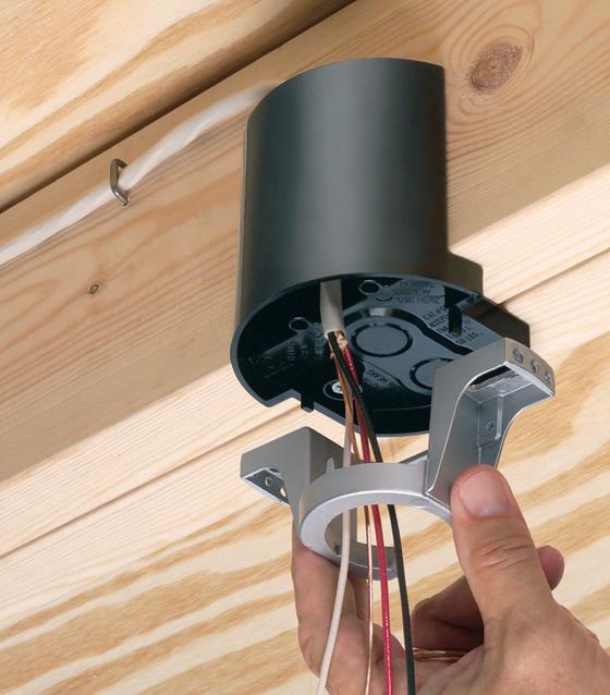
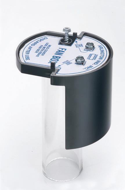
FAN FIXTURE BOX
Arlington’s heavy-duty, plated steel fan/ fixture box has an adjustable bracket that mounts securely between joists spaced 16" to 24" o.c.
Flush ceiling installations
FBRS415 is designed for ceilings up to 1-1/4" thick. For 1/2" ceilings, use the pre-bent positioning tab. For other ceiling thicknesses, bend along the appropriate score line.
• 15.6 cu. inch box ships with captive screws, mud cover, installed NM cable connector
sizes – as well as a variety of other products such as timers, disconnects, inlet boxes and more. UV rated, paintable plastic for long outdoor life.
Squared-off corners make them gangable so you can create the mounting base needed for the product you’re installing.
SMART ENERGY
The NEC distinguishes between different types of battery installations. Articles 480 and 706 both pertain to battery systems, but the application and requirements are different. Article 480 applies to traditional stationary battery systems that are to be used for emergency or standby power. These are legacy-style installations, using lead-acid battery banks to support emergency lighting, switchgear control, or an uninterrupted power supply system. These systems are designed to stay fully charged and only discharge when there is a loss of power. Because of the nature of these systems, the batteries are rarely cycled. The NEC views these systems as a fixed safety measure, focusing mostly on ventilation, disconnection means, overcurrent protection, and hazard signage. Article 480 treats the battery pack as a backup supply, not as an active energy source.
By contrast, Art. 706 was introduced to support the rise of BESS, which differs from standby banks in both technology and function. These systems use lithiumion and other advanced chemical batteries designed for large numbers of charge and discharge cycles. Article 706 includes provisions for the power management systems, thermal runaway protection, system controls, and utility interconnection integration. The Article outlines system-level controls to ensure proper charging, discharging, and coordination with other power sources. Article 706 also includes details regarding how BESS integrates multiple alternative energy courses (such as solar and wind) into one power system. In 2023, the NEC expanded Art. 706 with further guidance and informational notes, emphasizing its role in regulating actively managed energy storage that participates in the day-to-day operation of electrical systems.
To conclude, Art. 480 continues to cover conventional backup battery systems that sit idle until needed, whereas Art. 706 addresses dynamic energy storage technologies that operate as part of everyday energy use. Understanding the difference is crucial to applying the correct Code requirements in the ever-changing and rapid advancement of alternative energy generation and storage.
One of the leading concerns for many clients is the fire hazards associated
with a BESS. Section 706.5 of the NEC requires energy storage systems (ESSs) to be listed; two of the most common listings used in the industry are Underwriters Laboratories (UL) 9540 and UL 9540A. UL 9540, the standard for ESS and equipment, evaluates overall product safety by addressing electrical, mechanical, environmental, and functional performance. It also considers component compatibility, operation and maintenance, and integration with the electrical grid. UL 9540A, by contrast, is a test method that examines how an ESS behaves under thermal runaway conditions, including the potential for fire propagation and gas release. Together, these listings provide critical safety data and assurance for authorities having jurisdiction and are highly recommended for use in BESS installations. While NEC requirements and UL listings establish a strong safety foundation for fire mitigation, applying industry best practices adds an extra layer of protection and client reassurance. To address these concerns, many manufacturers equip their BESS enclosures with fire suppression systems, enhanced ventilation, and additional cooling features.
Fire suppression systems typically integrate three detectors (smoke, gas, and heat) that feed data to a central control panel. Based on this input, the system can automatically activate exhaust fans, trigger alarms with horn and strobe signals, and release extinguishing agents. The Figure above shows an example of a fire suppression system flowchart.
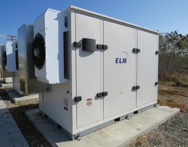
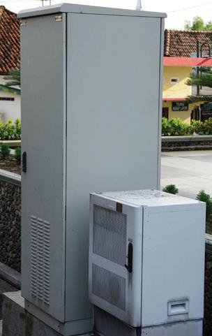
Section 706.20 requires ventilation for an ESS to be provided in accordance with the manufacturer’s recommendations and the system’s listing, leaving minimum requirements open to interpretation based on the specific equipment. It is therefore important to confirm with manufacturers that their base-level ventilation can sufficiently prevent the accumulation of explosive gases within BESS enclosures. As shown in Photo 2 on page 34, sufficient ventilation serves as a key safeguard, typically provided through exhaust fans that often work in tandem with air-conditioning units to maintain consistent air circulation and temperature control.
Additional cooling measures further reduce the risk of overheating and thermal runaway. In most manufacturers’ designs, air-conditioning regulates
An example of a BESS fire suppression system flowchart.
Suppression System Control Panel
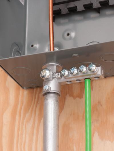
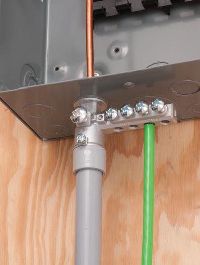
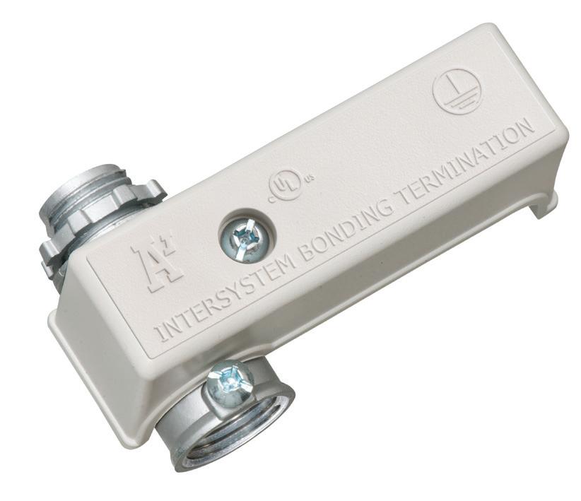
GROUNDING BRIDGE
MULTIPLE ZINC & BRONZE STYLES MEET NEC GROUND
Arlington’s heavy-duty Grounding Bridges provide reliable intersystem bonding between power and communication grounding systems. And handle multiple hookups of communications systems: telephone, CATV and satellite.
Our new GB5T comes with a Combination Threaded and Set-Screw hub for Threaded Rigid – or EMT Conduit.
Arlington’s zinc and bronze grounding bridges...
• Four termination points; more than required by the NEC
the temperature of the power control system (PCS), while self-contained liquid cooling systems manage the thermal demands of the battery cabinets. If the cooling systems are unable to maintain safe battery temperatures, then best practices call for equipping the BESS with over-temperature sensors that can shut down the system to prevent fires and thermal runaway.
Another leading concern for many clients is ensuring the long-term maintenance and reliable operation of BESS installations. Routine inspection and upkeep are critical for identifying potential issues before they escalate into safety or performance problems. While manufacturers provide maintenance checklists and guidance, it is important to consistently adhere to these schedules. Delaying or skipping scheduled maintenance can increase the risk of system failures, reduce operational efficiency, and compromise safety. Common maintenance practices include regularly checking
CONCLUSION
Staying aligned with the NEC is critical as solar PV and BESS systems become more common. Understanding key sections — such as Sec. 690.7 and Sec. 690.8 for circuit sizing, Sec. 690.43 for grounding and bonding, and the noted distinctions between Art. 480 and Art. 706 — helps avoid common violations. Combined with best practices for fire hazard mitigation, ventilation, and maintenance, these measures ensure safe, reliable installations and offer clients confidence in their energy systems.
system connections, monitoring battery performance and temperature, cleaning components as needed, and promptly replacing worn or damaged parts. To help ensure these tasks are carried out properly, many clients find it beneficial to establish a service agreement with manufacturers, local dealers, or certified service providers.
Josh Bristow is an electrical engineering consultant for CDM Smith. He specializes in water/wastewater on-site consulting and power distribution.
Matthew Smith, EIT, is an electrical engi neer with CDM Smith. He specializes in water/wastewater design and renewable systems.
Photo 2. The exterior of a BESS. Pictured on the leftmost exterior of the enclosure are the exhaust fan, air-conditioning unit, and emergency stop button.
CDM Smith
SNAP2IT® CONNECTORS
17SAVE seconds
Fully assembled, SNAP2IT® fittings handle the widest variety of MC cable AND THE NEW MC-PCS cables.
Compared to fittings with a locknut and screw, you can’t beat these snap in connectors for time-savings!
LISTED SNAP2IT ® CONNECTORS FOR NEW MC-PCS CABLE ...lighting & low voltage circuits in the same cable
• Fits widest range and variety of MC cable 14/2 to 3/3
AC, MC, HCF, MC continuous corrugated aluminum cable and MCI-A cables (steel and aluminum)...including the new MC-PCS cable that combines power and low voltage in the same MC cable
ANY Snap2It Connectors LISTED for MC cable are also LISTED for MC-PCS cable! These products offer the greatest time-savings.
• Fast, secure snap-on installation
• Easy to remove, reusable connector From cable Loosen screw on top. Remove connector from cable. From box Slip screwdriver under notch in Snap-Tite® Remove connector.
Easy to Snap into Box!
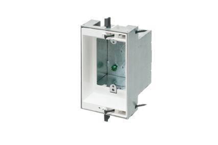
Large Volume FURRED WALL BOX
Arlington’s new Furred Wall Box® kit makes challenging outlet box installations fast and easy!
Versatile mounting options Our high strength FSB series outlet box kits are designed for use with existing 1x2 drywall furring strips – but can also be mounted directly to a concrete block wall between furring strips. Place the box or outlet where it’s needed.
Integral cable securement – No pullout! Accommodates GFCI and USB receptacles. Convenient kits simplify ordering of FSB1 and FSB2.
High-strength No breakage in cold weather
Integral Mounting Flanges
FSB2
FSB1 Single gang on Block Wall
Low Profile
NEW FSB12 * FSB22
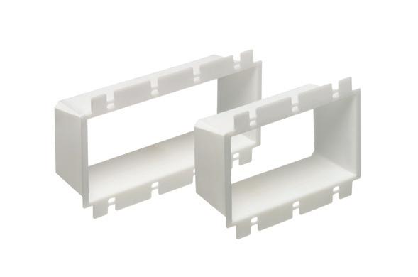
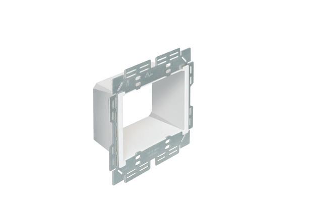
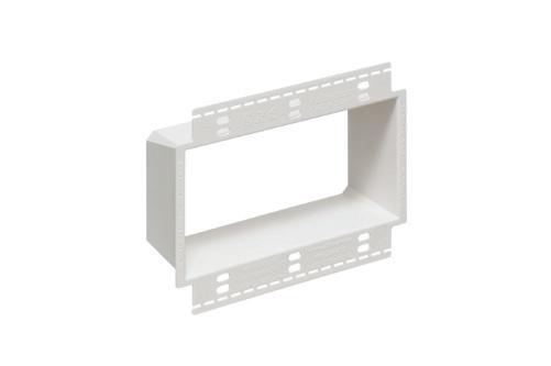
ADD OUR BOX EXTENDERS to BROADEN APPLICATION and USE
Furring strip flange Mounting Bracket
Base
Assemblies for 1/2" Wall Thickness & Standard Depth
Install on 1x2 Furring Strips or Block Wall with 1/2" Drywall
One-gang FSB12
Block wall flange Mounting
Our NEW Low Profile single and two-gang Furred Wall Box® base assemblies have 1/2" raised ring for use with standard wall plates.
They combine with Arlington’s Box Extenders to deliver installation solutions for wall thicknesses from 1/2" to 1-1/2" and varying device depths
• Integral cable securement – No pullout!
• For standard and GFCI devicesUses standard wall plates
• Single gang FSB12 - 17.0 cu. in. Two-gang FSB22 - 20.5 cu. in.
Add our BOX EXTENDERS for these specific conditions...
1 if Total Wall Layer Thickness is GREATER than 1/2" (up to 1-1/2") Add BE1 or BE2
if Using a Deep Depth Device with 1/2" Wall Thickness Add BES1 or BES2
or Dimmer
Bracket
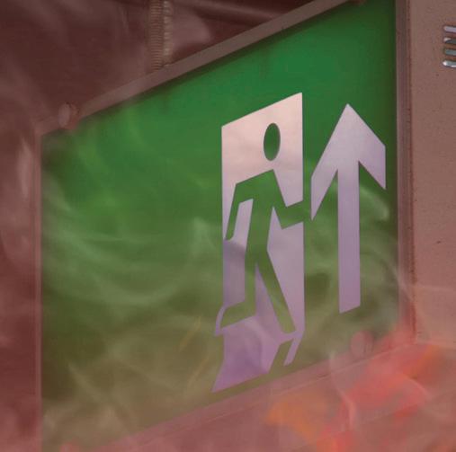
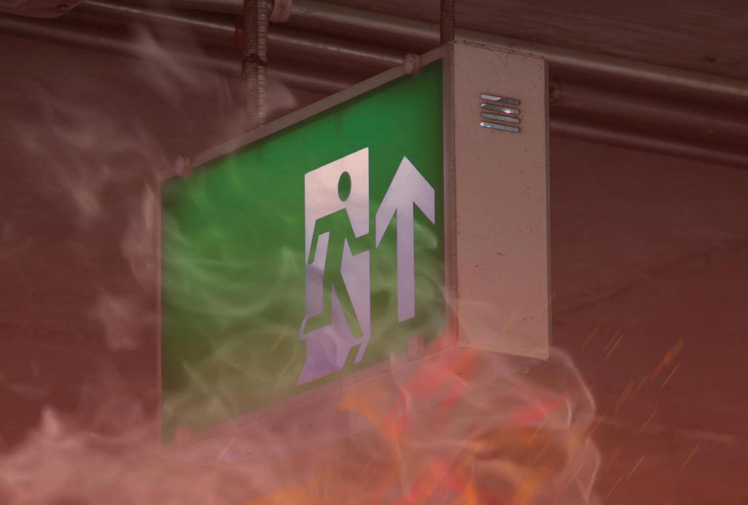
CUT THE CORD, KEEP THE CODE: WIRELESS CONTROL FOR CODECOMPLIANT EMERGENCY EGRESS
Because today’s performance-based codes focus on outcomes rather than wiring methods, networked lighting systems can deliver fail-safe egress illumination with streamlined installation and automated verification.
Emergency lighting has one job: keep people moving safely when normal power fails. Put simply, it’s the system that keeps a safe level of illumination — and power for lighting-related critical equipment — when normal power fails, so people can get out of the building safely. What makes it different is that it’s a life-safety system. So decisions can’t be driven only by cost or convenience.
In some applications, the right solution may be pricier than ambient lighting — though, as we’ll see, new technology can actually lower cost while improving emergency light quality. In addition,
compliance is performance-based, not product-based. As such, a UL mark alone doesn’t guarantee it was used in a well-designed project or the right application; the system tested on-site must prove required performance, as designed recommendations per building codes, including the expected maintained illumination for a minimum time.
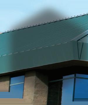
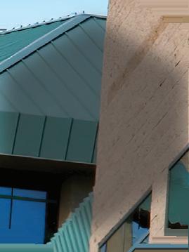
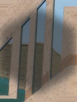
As for using lighting controls to provide the right emergency lighting at the appropriate time, the building codes themselves are largely technology-neutral, which is why controlled solutions are viable — as long as they meet the performance requirements. Although advances in lighting controls
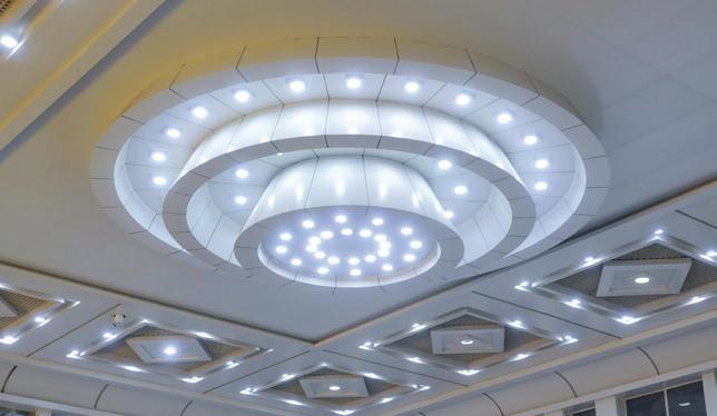
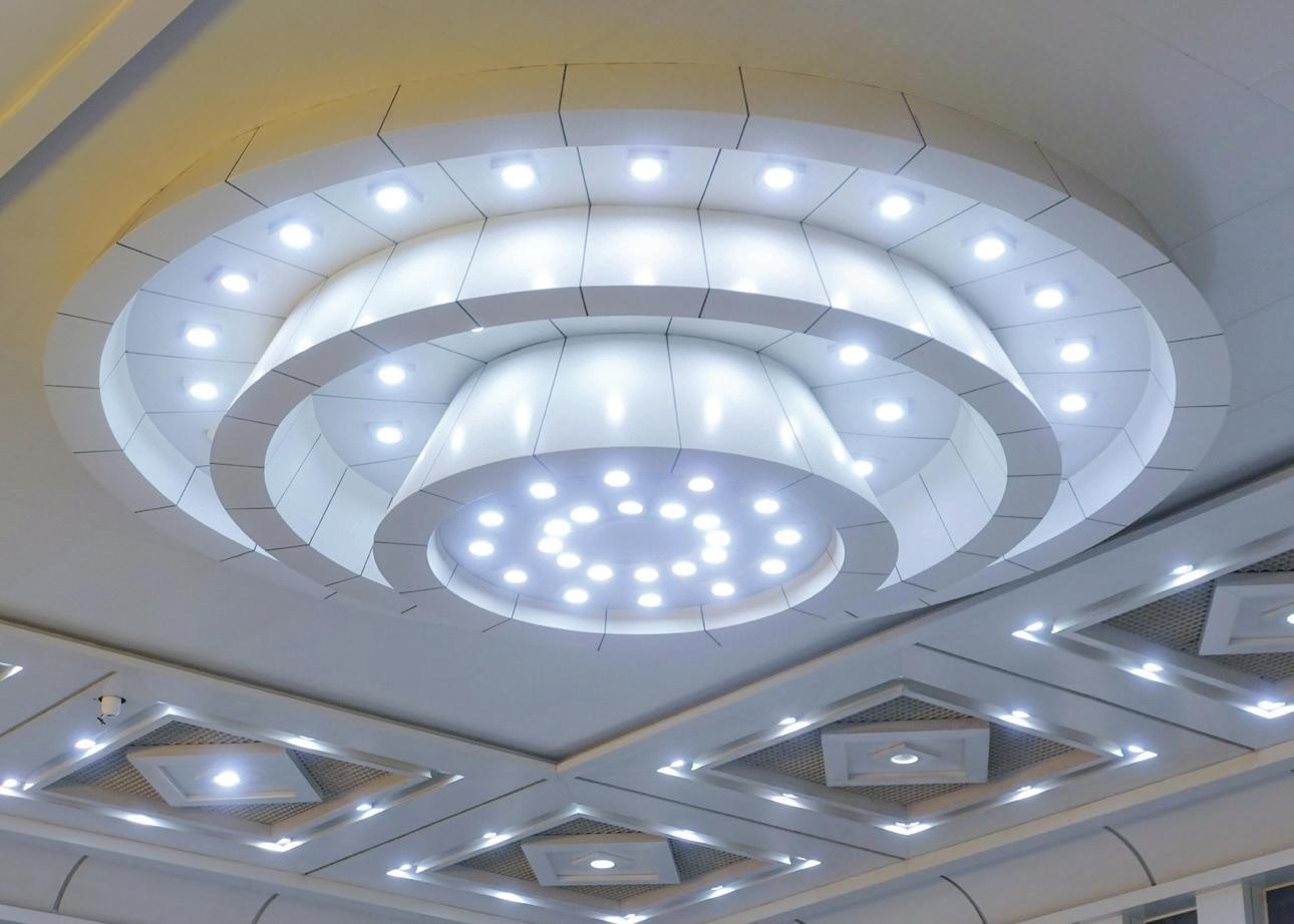
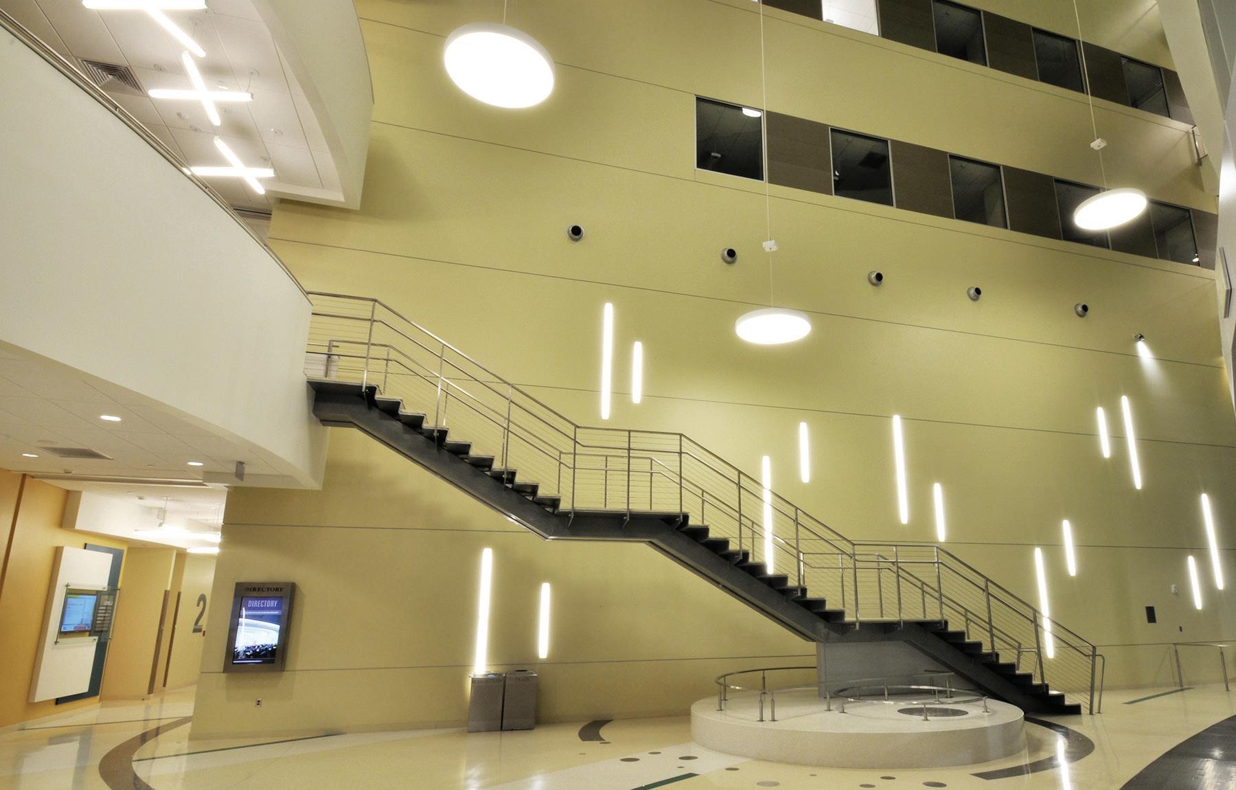
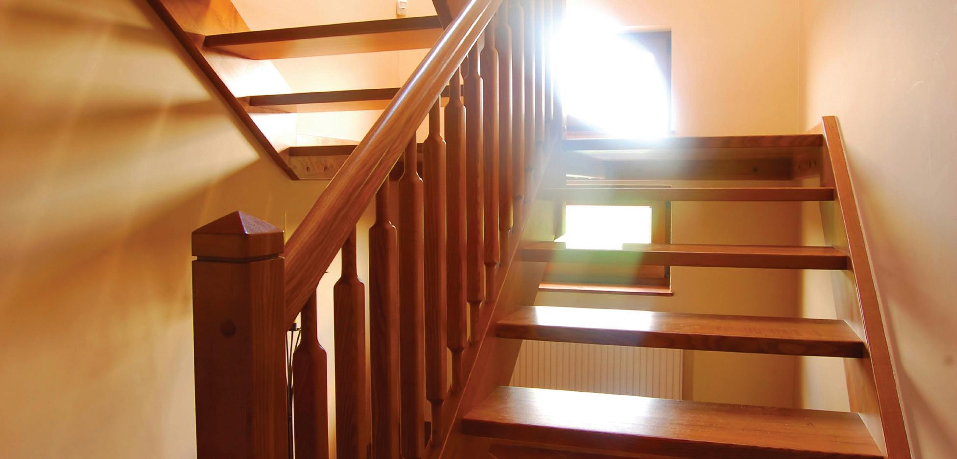
and energy management have made code compliance more complex, they’ve also unlocked better options — with higherquality emergency lighting, easier testing and maintenance, and simpler design and installation efforts. Educational facilities (Photo 1) are a great place to implement a modern lighting control system.
WHEN DID IT ALL START?
Did you know it all started with too many standards for sprinklers’ piping size and spacing back in 1895? Due to the multitude of options, some insurers and engineers united to recommend uniform sprinkler sizes and spaces. The group’s work resulted in NFPA 13, Standard for the Installation of Sprinkler Systems. The NFPA was founded in 1896 to bring uniformity to fire protection. One year later, the first National Electrical Code (NEC) set common safety rules for wiring. Shortly thereafter, by 1911, the NFPA had taken over sponsorship of the NEC and has maintained it ever since.
On the life-safety side, NFPA’s Committee on Safety to Life published the 1927 Building Exits Code after studying deadly fires; that lineage evolved into NFPA 101, Life Safety Code.
Today’s emergency lighting equipment and systems trace back to the 1927 Building Exits Code, which was founded on a simple principle: Occupants must not be left in the dark. A century later, that performance-based, technology-neutral foundation remains intact — focused on ensuring safe visibility and egress, regardless of whether activation comes by wire or radio.
Cooper Lighting
1. Modern connected lighting control gives educational environments much more flexibility.
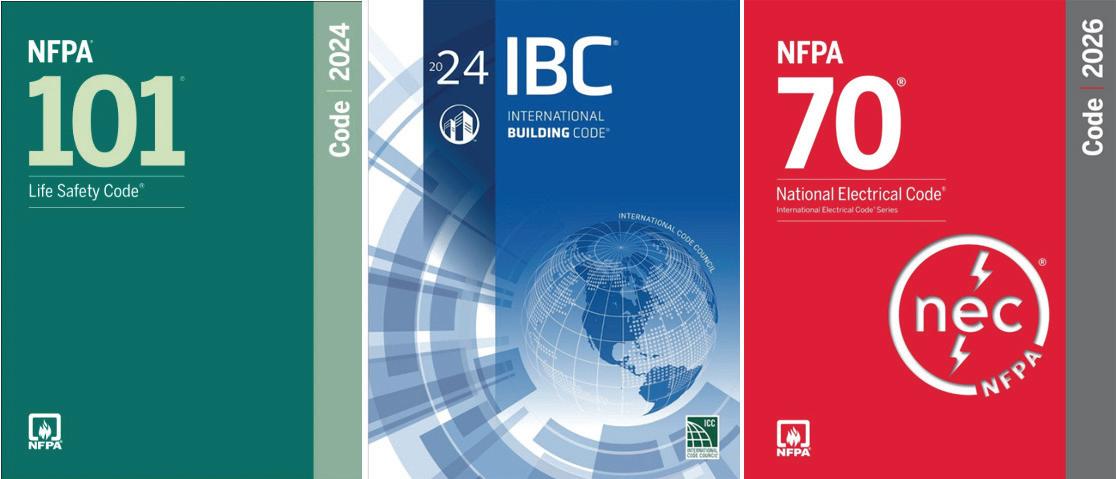
WHAT DOES THE CODE ASK FOR?
Think of it in three layers (Photo 2 on page 40). First, the building codes (NEC Art. 700, etc.) govern power sources, transfer equipment & systems, separation/identification of emergency circuits, testing, and documentation. This basically means that across adoptions of NFPA 101 and the International Building Code (IBC), designers must provide, along the means of egress, an initial 1 fc average (≥0.1 fc minimum) at the floor, allowed to decay to 0.6/0.06 fc by 90 min., with uniformity ≤ 40:1. Stairs carry a 10 fc requirement in normal operation. These values are technology-neutral: The code doesn’t mandate how you get there — only that you do, and that the system behaves automatically on power loss. NEC Sec. 700.24 clarifies directly controlled emergency luminaires vs. bypass/force-on methods; Sec. 700.11 sets rules for Class-2 emergency circuit identification, separation, and protection. Knowing that we have design guidance per safety codes, do you feel safer now? If you do, you shouldn’t. What about the products used? How do we know they were designed to support such requirements and in a sustainable way?
HERE COMES UL!
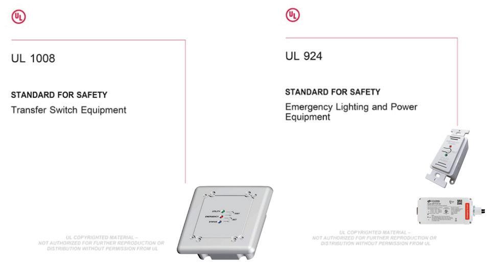
This is when product standards come in and govern what the equipment is listed to do (Photo 3 on page 40).
UL 924, Emergency Exit Signs , covers emergency lighting and power equipment: exit signs, unit equipment, micro- and central inverters, and emergency lighting control devices (ELCD/ALCR) that force luminaires to the emergency state. It also covers directly controlled emergency luminaires (DCEL) that accept a dedicated emergency input.
UL 1008, Transfer Switches, covers transfer switch equipment, including branch-circuit emergency lighting transfer switches (BCELTS).
Field rule: If you’re changing sources, that’s UL 1008. If you’re overriding control/forcing full output, that’s UL 924. We won’t address UL 1008 here because it’s not directly related to lighting equipment.
Do you feel safer knowing we have design guides and certified products? I hope so. But we’re not done yet. The equipment and systems still need to be inspected and tested.
AUTHORITY HAVING JURISDICTION
This step involves the Authorities Having Jurisdiction (AHJs), defined by NFPA as the organization or person that enforces the code or approves an installation, reviewing listings, the sequence of operations, and the test plan — and then witnessing tests on
site. The entire system needs to be evaluated as installed and eventually accepted by the AHJ.
The AHJ evaluates performance on site. If approved, they enable a Certificate of Occupancy (CO). Non-compliance can trigger corrections or a provisional CO with deadlines. After the building is opened to occupants, upkeep is mandatory: the 2026 NEC Sec. 700.4 adds Commissioning and Servicing — Tested Periodically (B) requires a testing schedule approved by the AHJ, and Record Keeping (D) requires written or digital records available to those who design, install, inspect, maintain, and operate the system. In parallel, 2024 NFPA 101 §7.9.3 requires periodic testing of emergency lighting equipment.
Who plays AHJ? For example, in New York City, it’s the Department of Buildings (DOB) with FDNY inspectors. In Canada, it’s typically the municipal building official (often alongside the provincial electrical authority).
How does this happen in reality, and what are the typical solutions? We can separate emergency lighting control solutions into four categories.
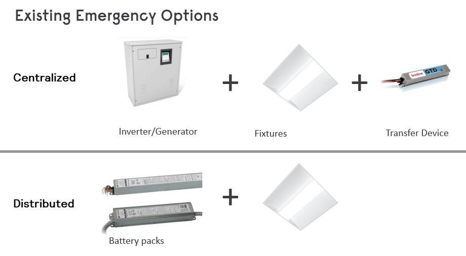
CENTRALIZED VS. DISTRIBUTED
Centralized vs. distributed emergency lighting boils down to where the backup power lives and how it reaches the
Photo
luminaires (Photo 4). In a centralized approach, a generator or central lighting inverter (EPSS) feeds selected circuits so the normal luminaires ride through an outage. This is a great option for large corridors and open areas because it means fewer batteries to service, and it results in clean ceilings. However, it can mean heavier upfront infrastructure and careful circuiting.
In a distributed approach, backup power sits at the edge — unit equipment (bug-eyes/combos), LED emergency drivers inside fixtures, or micro-inverters per fixture/zone. This configuration is ideal for retrofits and offers targeted wayfinding with minimal new conduit. However, it spreads batteries and maintenance across the floor.
Most modern designs blend both: centralized coverage for big spaces, distributed devices where wiring is hard — all coordinated by code-compliant controls (UL 924/UL 1008) to ensure maintained or normally-off paths meet 90-min., illumination, and fail-safe requirements.
MAINTAINED VS. NONMAINTAINED (WHY IT MATTERS WITH CONTROLS)
• Maintained (normally on): part of everyday lighting; must force to emergency when power is lost — even if the space was dimmed. Use ELCD/ALCR or DCEL.
• Non-maintained (normally off): only energizes in an outage, typically via inverter/generator or local battery.
SHOW ME HOW
Now it’s time to review traditional and newer approaches for emergency lighting. It’s easier to illustrate these concepts with
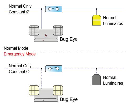
fewer words and more visuals. See graphics on page 42 for the following scenarios: Approach No. 1: Unit equipment (bug-eyes/combos) and LED emergency
Photo 2. Designers must consider all building codes when specifying electrical systems for emergency lighting applications.
Photo 3. UL 924 and UL 1008 should be used as design guides for specifying electrical products.
Photo 4. Centralized vs. distributed emergency lighting at a glance.
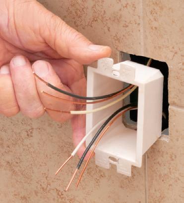
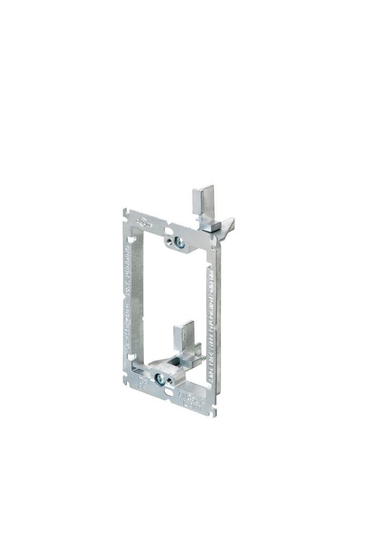
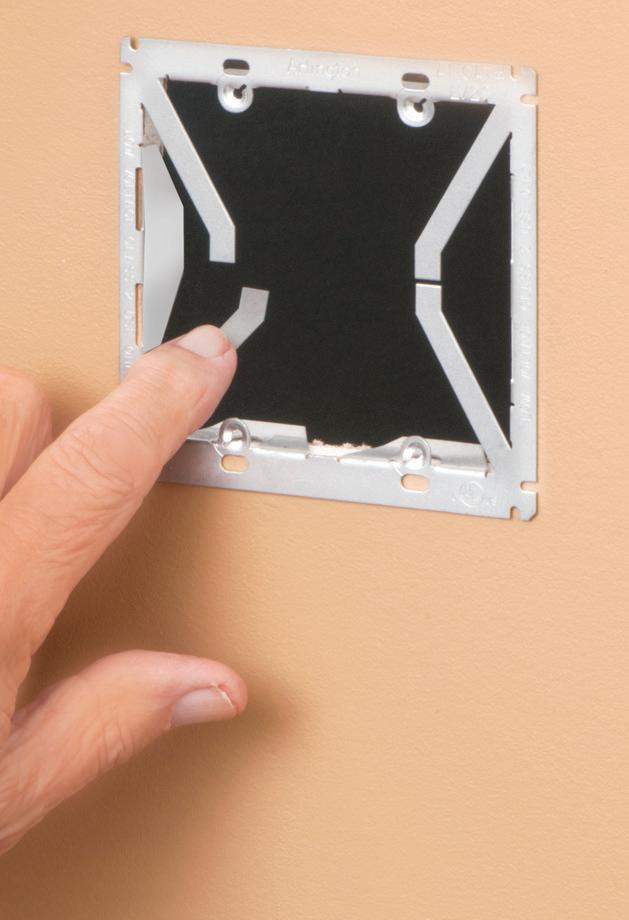
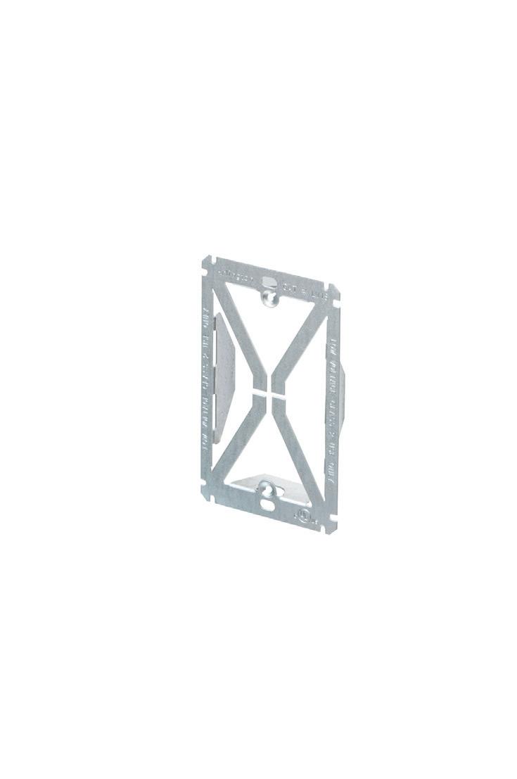
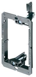
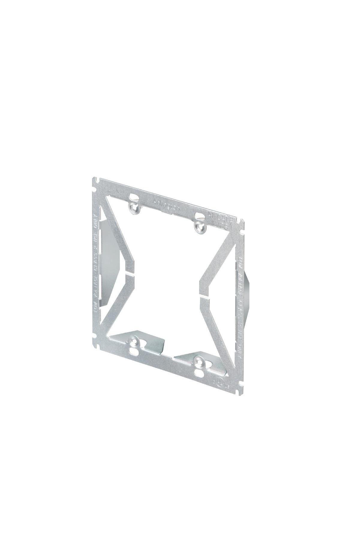
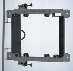
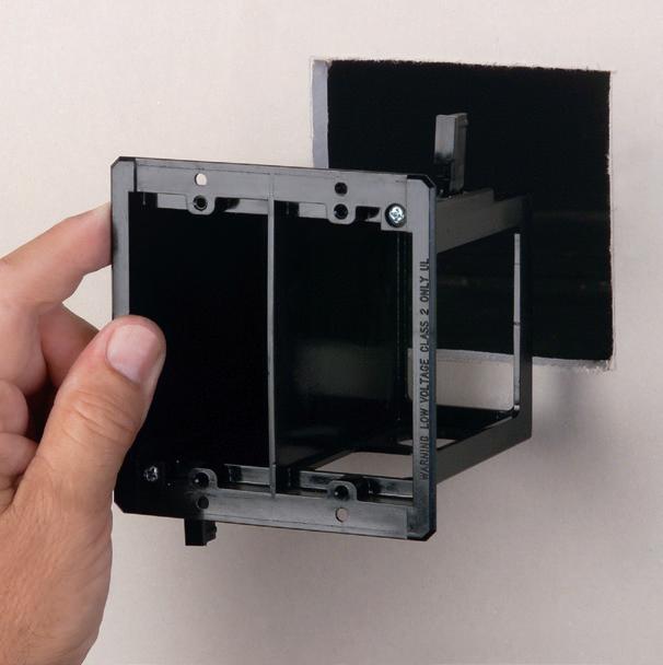
Arlington’s Low Voltage Mounting Brackets are the solution for fast and easy cut-in installation and mounting of Class 2 communications, computer and cable TV wiring and connections.
Introducing METAL low voltage mounting brackets for EXISTING or RETROFIT construction...
LV1M and LV2M COMMERCIAL GRADE
• Extra rigidity and stability where performance and visibility are important or critical
• Threaded holes for easy, fast device installation
• Adjustable bracket for 1/4" to 1" wall board thicknesses
Our LV1S and LV2S PLATED STEEL bracket design, provide excellent stability and secure installation of low voltage devices in 1/4" to 1-1/4" walls - without an electrical box.
drivers provide local battery back-up where circuits are hard to reach, or you want targeted wayfinding light (Fig. 1).
Approach No. 2: LED emergency drivers provide local battery back-up where circuits are hard to reach, or you want targeted wayfinding light (Fig. 2).
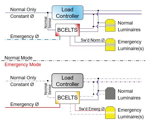
Approach No. 3 : Central inverters/generator (EPSS) keep normal luminaires on during outages — great for large open areas and corridors, and to reduce battery proliferation (Fig. 3).
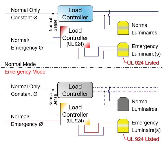
Approach No. 5: For controlled spaces, add UL 924 ELCD/ ALCR (bypass/force-on) or specify DCEL luminaires so dimmed scenes cannot suppress the emergency state (Fig. 5).
THE CONTROL DILEMMA
Can lighting controls used to enhance lighting quality and energy savings also play a role in emergency lighting? After all, this is a lighting control article, right?
In a lot of projects, lighting controls are required by energy codes to turn lights off or dim them during normal operation. Yet emergency lighting must provide a reliable
path of egress that those same controls cannot turn off. How can two seemingly opposite requirements coexist — sometimes even within the same luminaire?
Fig. 2.
Fig. 1.
Fig. 3.
Fig. 4.
Fig. 5.
Mitch Hefter Consulting
Mitch Hefter Consulting
Mitch Hefter Consulting
Mitch Hefter Consulting
Mitch Hefter Consulting
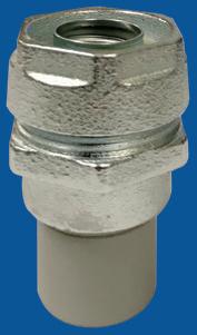
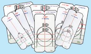
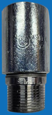
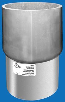
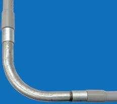
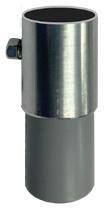
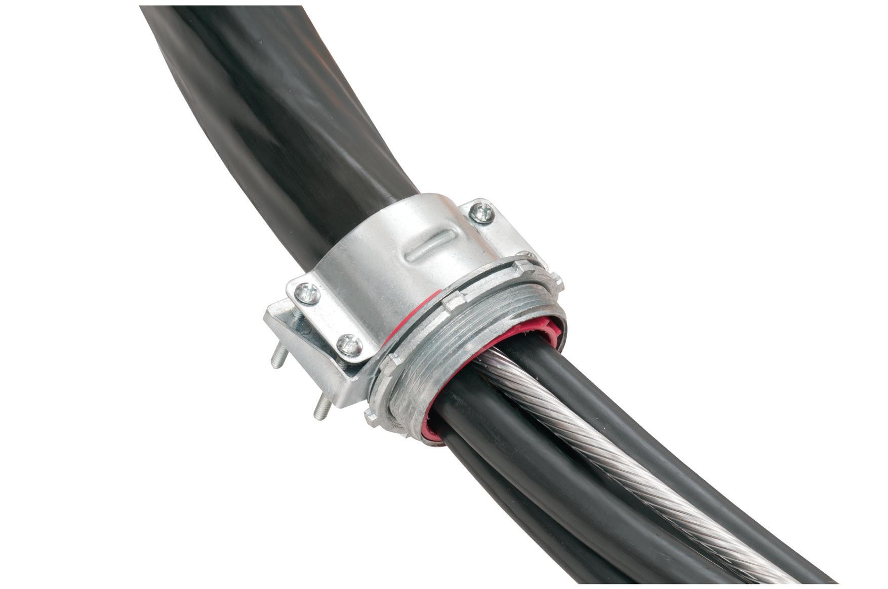
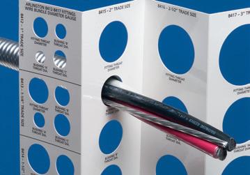
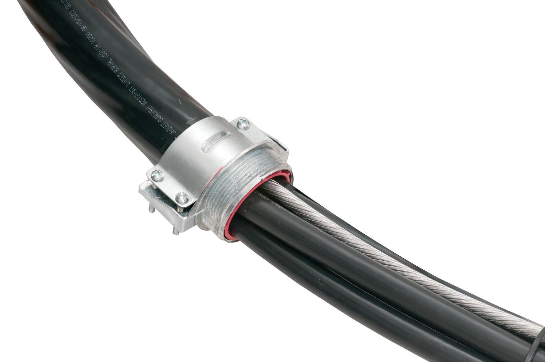
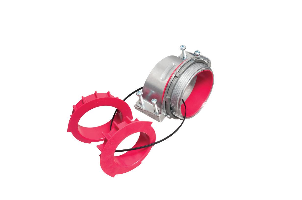
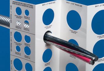
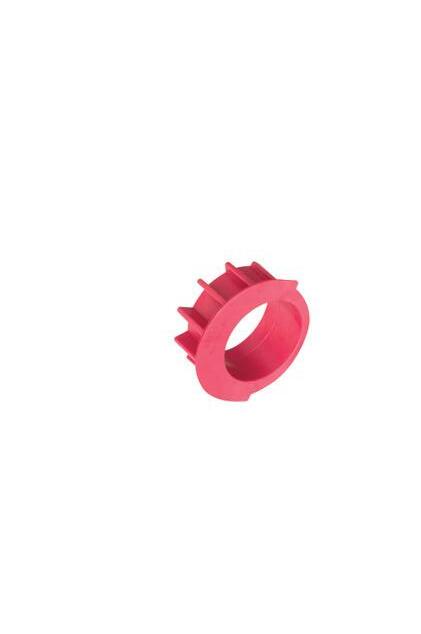
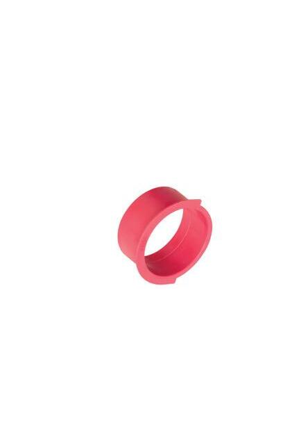
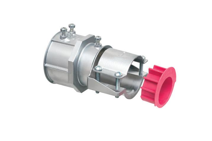
Perfect for data center remote power panel feeds, panels, equipment feeds and EV Chargers in parking garages, Arlington’s Listed CableStop® Transition Fittings deliver the efficient, cost-effective way to transition feeder cables to 1.25", 2.5", 3" and 3.5" EMT, IMC and RMC conduit in protective drops, risers and feeds to panels and equipment. Our new CableStop fittings integrate our patented, versatile and SKU-reducing 8412 series cable fittings, with Arlington conduit fittings, allowing for easy transitions to larger knockout sizes.
Available with set-screw or compression connections into 1.25", 2.5", 3" and 3.5" conduit, they ship with multiple end stop bushings that vary the size of the opening – along with a free template select the right bushing for the cable.
Wiring Diagram DIMMABLE EMERGENCY LIGHTING SYSTEM
diagram
In May 2020 (effective May 2022), UL added Clause 29A to UL 924 and tied it to the ELCD test sequence in 47.2(c), which states that if an Emergency Lighting Control Device (ELCD) provides control functions — on/off/ dim — it must continuously monitor the “normal-power present” signal for its controlled branch circuit. That monitoring can be wired or wireless, but it must remain functionally independent of the emergency power feeding through the device. In other words, even while passing emergency current, the ELCD must still watch normal-power status and respond automatically and fail-safe.
This is the technical bridge that finally lets general lighting controls participate in emergency-lighting control. When implemented with UL-listed ELCDs or directly controlled emergency luminaires (DCELs), the same control infrastructure that dims, senses, and reports during everyday use can — upon loss of normal power — automatically shift into emergency mode, delivering required illumination while preserving code compliance. Why? Because the key factor is a system with a fail-safe behavior: The control system may add intelligence, but the UL-924 device guarantees that light comes on even if the regular power signal monitored by the control system disappears, or if the system overall disappears.
There is no pre-set dimming anymore, nor is there an end-user changing the light levels from a wall station.
AREN’T WE TRYING TO DO THE OPPOSITE PER THE LATEST ENERGY
BUILDING CODES?
Yes, both building and energy codes are designed to coexist: Life safety wins in an emergency, and energy efficiency governs in normal operation. Most energy codes (Title 24/ASHRAE/IES 90.1, and IECC) exclude emergency lighting that is normally off from lighting power and control requirements, so dedicated emergency luminaires aren’t penalized for being “ready-but-off.” For maintained luminaires (used every day), you still meet energy rules (dimming, occupancy, daylighting) until normal power is lost; then, a UL 924 override or directly controlled emergency input takes priority and drives the required emergency level for 90 min. Here’s a summary of U.S. energycode exceptions.
• ASHRAE/IES 90.1 excludes normally off emergency lighting from its lighting power and control scope.
• IECC 2021 likewise exempts 24-hour emergency/security lighting and emergency egress lighting that is normally off.
• California’s Title 24 allows up to 0.1 W/ft2; of designated means-of-egress
lighting to remain continuously on without the usual area/automatic shutoff controls.
SHOW ME THE MONEY
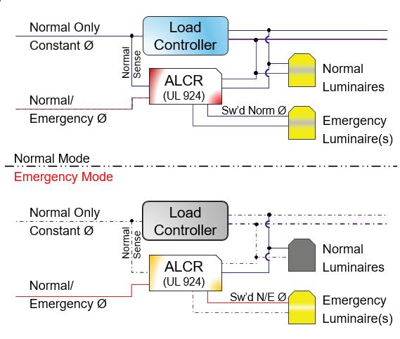
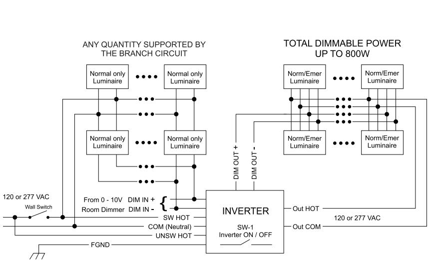
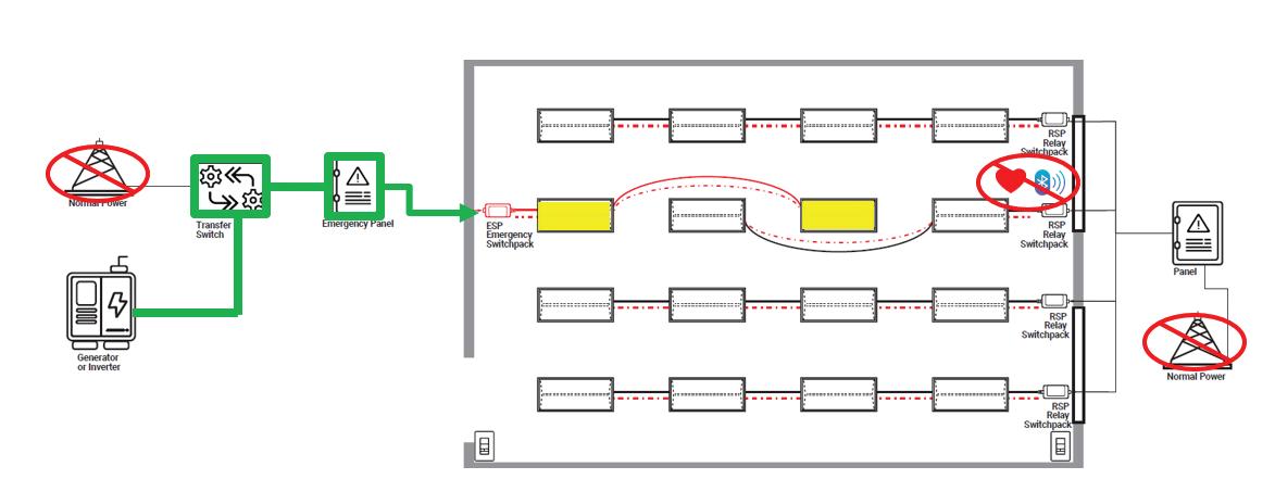
Using a 0–10V dimmable luminaire with central inverters with 0-10V dimming capabilities lets you keep everyday lighting quality and still meet emergency egress requirements — with better, more uniform light during outages (Fig. 6). Under normal power, the inverter simply passes through the room’s 0–10V control, so your maintained luminaires behave like any other dimmable load. If normal power fails, the inverter generates AC from its battery and takes control of the 0–10V line, driving the luminaires to a predetermined emergency level that fits the inverter’s rating (e.g., a 40VA luminaire in normal mode can be auto-dimmed to ~10VA in emergency). The result is code-minimum egress illumination with less glare, better contrast, and more luminaires on (at a safe reduced level), while acknowledging real-world inefficiencies may modestly reduce the total achievable load.
DALI
As we know, DALI control systems communicate on a low-voltage control bus to LED drivers and other control
Fig. 6. Wiring
of a sample dimmable emergency lighting system.
Super-secure installation!
Our lowest cost, L-shaped fan/fixture box mounts to single or double joists with a captive center screw. No loose parts!
screws ship captive, ready to install box and bracket.
For 1/2" or 5/8" drywall
Fast, easy installation
• Locator posts assure proper positioning of fan/fixture bracket • 2-hour Fire Rating
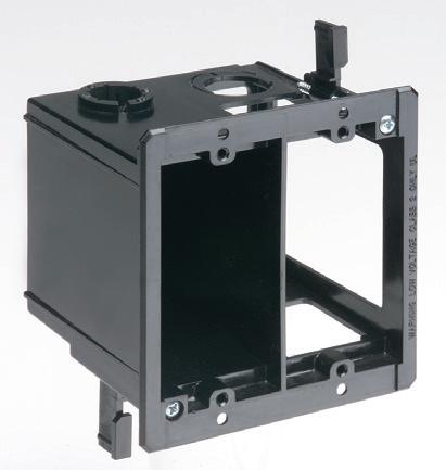
This convenient combo box has power and low voltage openings in the same box for a neat, time-saving installation.
The box adjusts to fit wall thicknesses from 1/4" to 1-1/2". Mounting wing screws hold it securely in place.
• 2-Hour Fire Rating
• Low voltage side has a combo 1/2" and 3/4" KO for raceway
• Includes NM cable connector (power side)
Product info aifittings.com/ landing/ combo-boxes
and
projects. There's more room in the box for wires and it installs horizontally or vertically to properly position low voltage connections behind the TV.
• Ideal for home theater systems: multiple connections for sound systems, satellite TV, CATV, DVRs
• Brackets for neater cables, with a 1-1/2" knockout for ENT and other low voltage wiring
• Box mounts to stud in new work; for retrofit, mounting wing screws secure
gear. During an emergency, the power continuity still comes from your EPSS (generator/central inverter) or local batteries. In normal operation, DALI runs scenes, occupancy/daylight, and keeps DALI emergency devices (IEC 62386-202) on a schedule for self-test and status reporting. When normal power is lost, two things happen: (1) the emergency power source keeps the designated circuits/luminaires energized, and (2) the emergency input/ logic takes over — either a UL 924 interface forces maintained luminaires to the required output (bypassing dimming), or DALI emergency control gear inside the luminaire automatically switches to its emergency state at a defined level and logs the event. Because the emergency behavior lives in the listed device, luminaires go to (and hold) the coderequired output without relying on the central controller, while DALI still gives you grouping, test automation, and fault reporting to prove compliance.
Keep in mind that a DALI system, when disconnected, doesn’t fail to high as 0-10V. In addition, the emergency lighting scenes need to be programmed. Self-contained emergency is included as part of DALI-2 certification. It typically includes support for function and duration tests, next to drivers going into emergency mode upon mains power failure.
DALI Alliance released to its members a new Part 254, which extends the emergency specifications with information on batteries. Although not released yet or part of the certification program, there is work being done by the DALI Alliance around centrally supplied emergency lighting.
DMX512
Similar behavior can be achieved with a DMX512 system. This is a good solution for theatrical lighting-related applications, such as theater or sports-related environments. DMX512 is a unidirectional show-control protocol that streams levels to luminaires; it doesn’t provide power continuity — that still comes from your EPSS (generator/central inverter) or local batteries.
For egress lighting, you must make DMX fail-safe: Insert a UL 924 emergency interface (or ELCD/ALCR) that,
Overview — Normal Operation
on loss of normal power or on an emergency contact, overrides DMX and drives designated channels/luminaires to the required emergency level (typically full). Don’t rely on a console or “hold last look/blackout” loss-of-signal behavior; instead, wire an emergency input from the EPSS/fire alarm/inverter to the UL 924 device or architectural DMX controller’s emergency input so the scene changes automatically. Document which DMX universes/channels are egress, show that dimming is bypassed in emergency mode, and keep the emergency
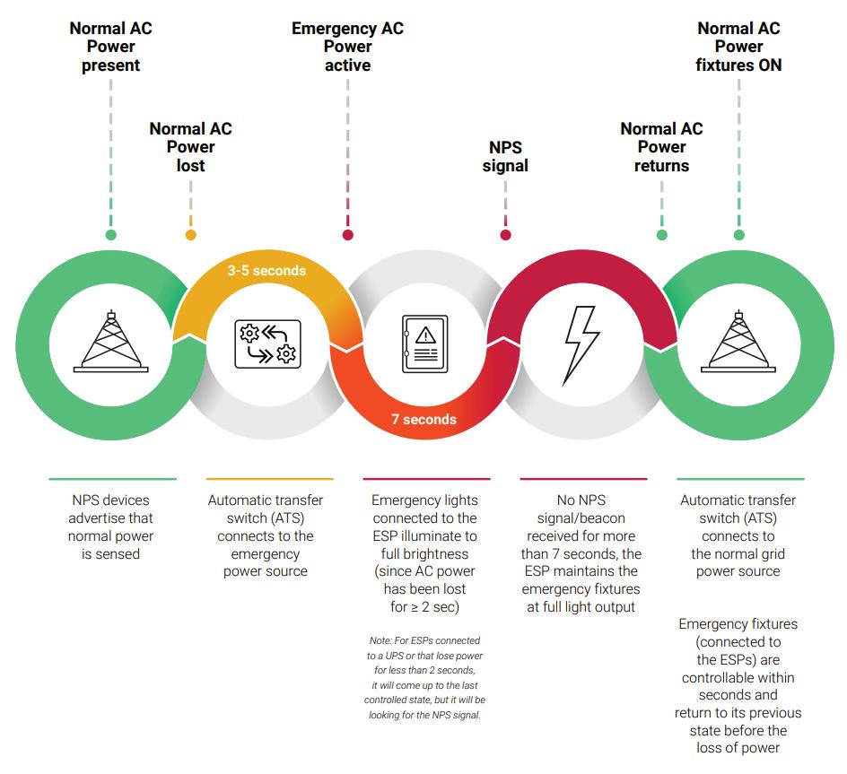
Fig. 7. Full sequence of operation when normal AC power is interrupted.
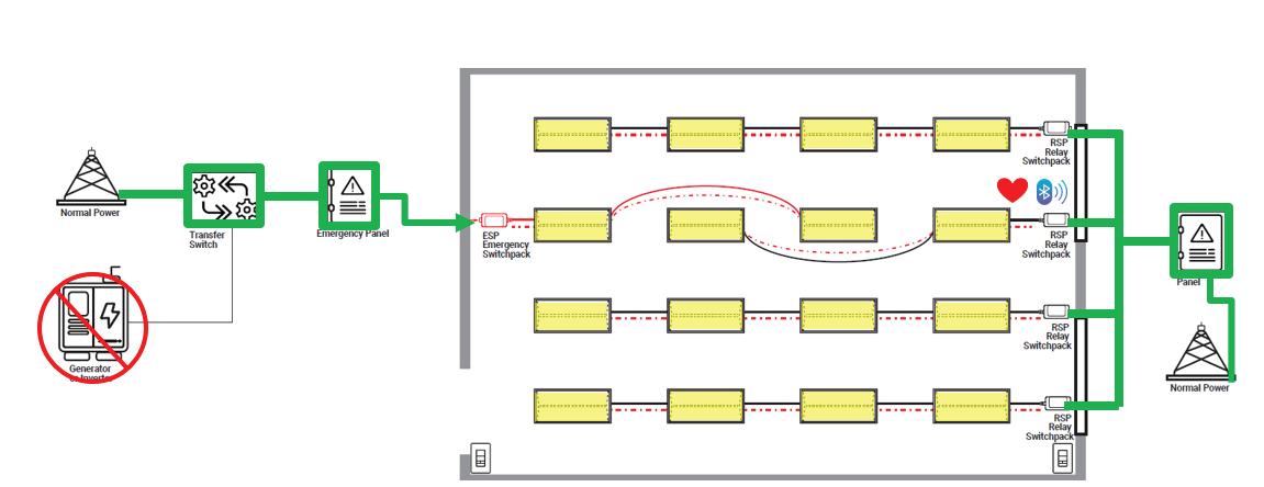
Fig. 8. Schematic illustrating normal operation. WaveLinxEM
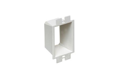
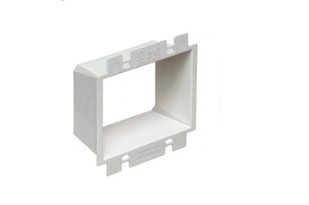
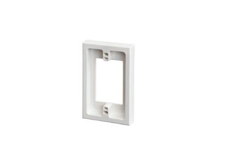
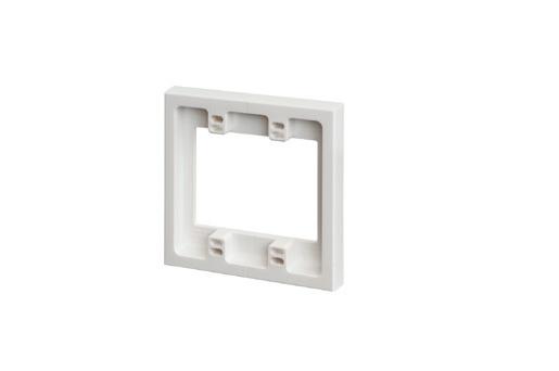
LISTED BOX EXTENDERS
Arlington’s variety of cULus Listed Box Extenders extend set back electrical boxes up to 1-1/2".
Made of heavy-duty, 105°C continuous use 94V0 rated, flame retardant plastic, they level and support wiring devices, while protecting wires against damage and stripping.
Choose the one that’s right for you!
BE1, BE2, BE3, BE4...Single-, two-, three- and four-gang, and BE1R for round or octagonal boxes...
Box Extenders
device support in oversized or mis-cut wall openings, available in single-, two-, three- and four-gang, (patented BE1X, BE2X, BE3X, BE4X.)
Our new heavy duty, COMMERCIAL-GRADE steel support plate! As shipped, single and two-gang BE1XLS and BE2XLS work with maxi cover plates, but they’re and standard plates. Convenient. Saves time. Great for poorly cut drywall.
For all standard devices, switches and GFCIs, our box extenders comply with NEC Article 314.20 for set back boxes.
circuits/luminaires energized by the listed source. If you use RDM/sACN for monitoring, treat it as supervision only — the listed UL 924 override is what satisfies the life-safety requirement.
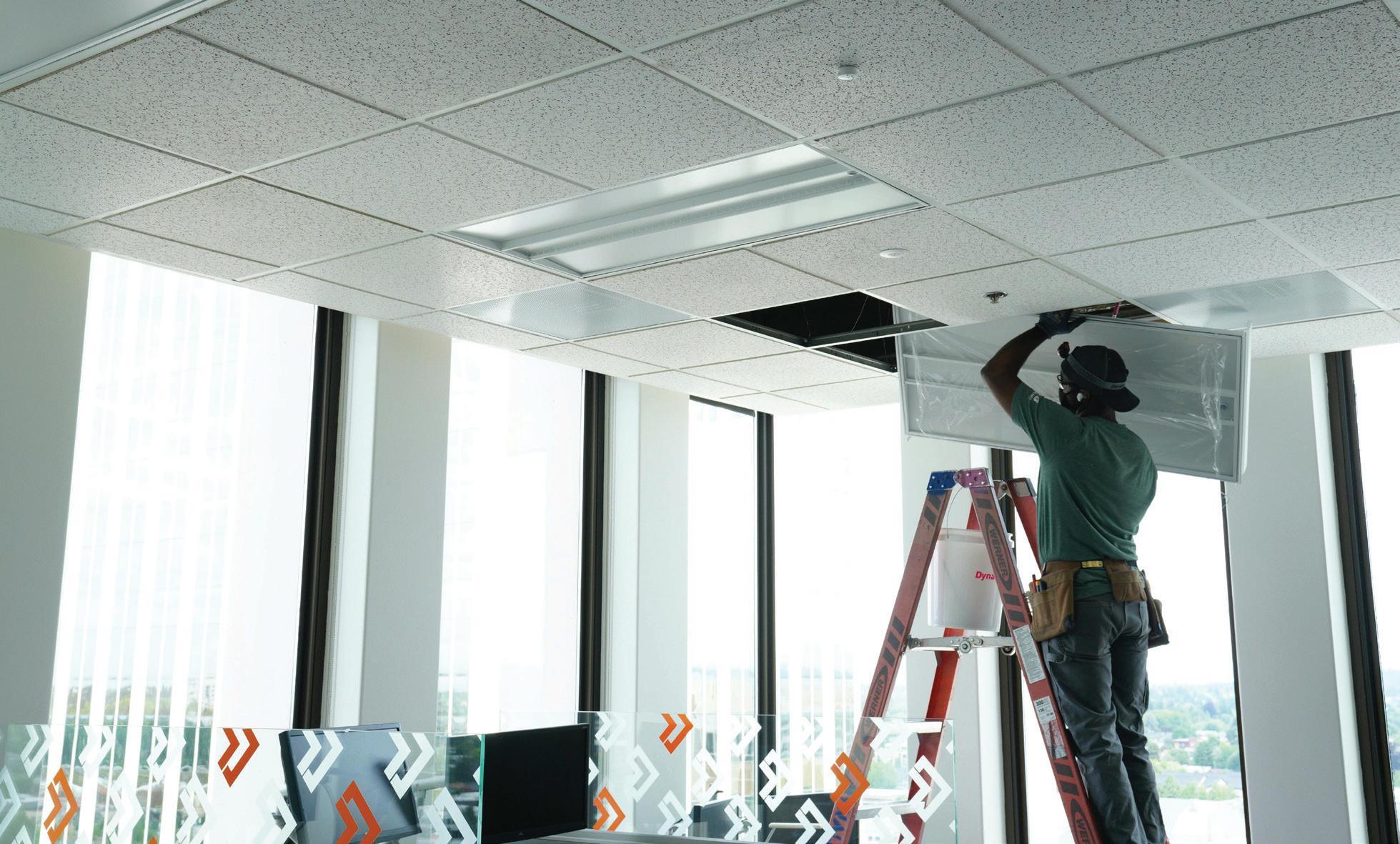
HOW ABOUT WIRELESS SOLUTIONS?
The recent twist is that we can often deliver those outcomes with far fewer new wires by pairing listed emergency devices with a wireless control/ supervision layer. The result is faster retrofits, cleaner ceilings, and better testing/ records without compromising life safety.
Figure 7 on page 46 illustrates the full sequence of operation when normal AC power is interrupted. Under normal conditions, NPS devices broadcast that electric utility power is present, and all luminaires operate in their normal, controlled mode. When normal power is lost, the automatic transfer switch (ATS) shifts to the emergency source within 3 to 5 sec. After 2 sec of power loss, emergency luminaires on the ESP drive to full output. If no NPS signal is received for more than 7 sec, the ESP keeps those emergency lumianires at full brightness until normal AC power is restored. Once electric utility power returns, the ATS reconnects to the grid, and the emergency luminaires quickly transition back to their previous, nonemergency lighting state.
This solution includes selected lumianires to be wired to the emergency power system and deliver emergency lighting, and other selected luminaires providing the normal power signal (NPS), sometimes referred to the heartbeat or beacon, to communicate that the regular power is present on site (Fig. 8 on
page 46). Wireless is not your life-safety source; the emergency power source and any power transfer devices remain your hard-wired and listed source.
The wireless solution, mostly a mesh network solution, needs to be designed with layers like critical plumbing: Stagger broadcasts, avoid network-wide floods, and ensure each emergency device has a local fail-safe path that does not depend on receiving a packet at the worst moment. In other words, optimize to prioritize emergency beacon signals, versus traditional control commands such as manual switch dimming, daylighting override, or a scheduled dimming action for a specific zone. If the beacon signal isn’t prioritized and is not received by an ambient luminaire acting as an emergency luminaire, it will default to high or its emergency lighting pre-programmed level. Fail-safe, but unnecessary overrides on-site are to be avoided (Fig. 9).
The mesh continually heartbeats the NPS beacon signal as defined by UL924 and seen earlier in the text; if heartbeats stop, emergency devices go to emergency light level output, something their full output or other planned leveler per minimum level requirements. Outside emergency lighting mode, an override command can be sent so luminaires go to the required emergency state on loss of normal power or control for testing, or site inspections.
The same system backbone can provide supervision and testing with an instant access to the status of your system and constantly monitor is status, and not only when scheduled for testing or inspection. It can automate and perform all required testing monthly 30-sec and annual 90-min. tests, store digital logs and
or email reports — a must for AHJ audits, with no searching for reports during an inspection. There are no ladders, no pushing buttons, and no documentation; reports can be easily exported to prove the system status is 100%.
CONCLUSION
The bottom line is emergency egress lighting isn’t about gadgets — it’s about outcomes: the right light, for long enough, every time. The good news is that modern, technology-neutral codes let you pair proven life-safety hardware (UL 924/UL 1008) with smarter control layers — wireless meshes, DALI Emergency, 0–10V with inverter auto-dim, and even DMX with UL-924 overrides — to deliver better visibility, simpler installs, and automated testing/records.
If this article sparked ideas, take the next step by piloting a small zone that blends your everyday controls with a listed emergency method, document the fail-safe sequence, and review it with your AHJ. Then scale what works — add selftest reporting, digital logs, and wireless supervision — to reduce OPEX (operating expenditures) while raising safety and light quality. Cut the cord where it helps, keep the code where it counts, and keep learning — because the fastest path to safer buildings is staying current on the tools that make compliance easier and outcomes better.
Mercier, P.Eng., is strategic marketing manager for IoT and connected systems for Cooper Lighting Solutions, a division of Signify (formerly known as Philips Lighting), based in Peachtree City, Ga. He can be reached at martin.mercier@ cooperlighting.com.
Fig. 9. Schematic of backup power operation.
From lettuce to cannabis, LEDs are becoming a major technology in horticulture lighting. But energy efficiency isn’t the only business driver.
By Tim Kridel, Freelance Writer
PPE stands for personal protective equipment — unless you’re working in horticulture lighting. Then it’s also short for photosynthetic photon efficacy, which measures the amount of electricity used to generate light that plants can use to grow. And not all light is created equal. Some wavelengths are better than others when it comes to optimizing a crop’s maturity, flavor, shelf life, cannabinoid profile, and other characteristics that directly affect the grower’s competitiveness and bottom line.
Those are just a few examples of artificial lighting’s role in controlled environment agriculture (CEA) facilities, which include greenhouses, warehouses, vertical farms, and even
caves. The CEA market will grow from nearly $10 billion this year to $27.7 billion by 2035, Business Research Insights estimates.
LED lighting is helping enable that growth. For years, it struggled to get a toehold in CEA, which was dominated by technologies such as high-intensity discharge (HID). That’s changed.
“The technology and cost for LEDs was not there in terms of ROI for most growers,” says Jud McCall, Hydrofarm Commercial CEA food and floral director. “The promise was, but the output, spectrum, and cost per unit were just not practical. This kind of reached an inflection point in 2020 to 2021. Up to that point, we were selling [about] 80% HID, but then it just flipped in the space of maybe 12 to 16 months to 80% LED.
This happened due to lower cost along with better quality, spectrum, and output on newer LEDs.”
That trend continues.
“In 2024, total lighting sales based on our own market characterization was about 60% LED, which I think is a big indicator that the industry is coming along in terms of new facilities being built,” says Kasey Holland, DesignLights Consortium senior technical manager for horticultural lighting. “That being said, in most of the CEA space, the greenhouses and legacy infrastructure are still relying on non-LED technology. LED adoption is not lagging behind anymore, but I would estimate the CEA industry is probably not even 15% LED yet.”
For electrical contractors and design firms, that relatively small installed base
means ample opportunities over the next several years to help growers upgrade existing CEA facilities to LED.
“We still do see some high-pressure sodium and HID lights being sold, but that is dropping off quite significantly in the last year or two in favor of LED,” says Chris Bezuyen, who manages Signify’s North America team of application engineers for the traditional horticulture and cannabis markets.
MORE LIGHT FOR LESS MONEY
One major and obvious reason for LED adoption is energy efficiency.
“They’re selecting LED instead of HID or HPS because they can achieve higher light levels for the same electrical energy input,” Bezuyen says. “Generally, they can achieve 30% to 40% higher light levels watt for watt.”
Efficiency doesn’t just save money. It can also help make money by enabling each watt to feed more plants.
“Leveraging more energy-efficient technology can actually allow them to scale without using more energy,” Holland says. “That’s definitely a big value prop for energy-efficient technologies.”
LEDs still have a price premium compared to traditional horticulture lighting technologies. But that up-front cost is something growers know, unlike the wild card of electric rates three or five years from now, especially if hyperscale data centers sprout up nearby.
“We can fairly easily demonstrate a rapid ROI, especially with the everincreasing energy costs,” Bezuyen says. “That ROI becomes more and more attractive every quarter.”
Utilities also see value in LED, which is why they incentivize them.
“With rising energy costs, the 40% to 60% energy savings of LEDs are vital,” says Kassim Tremblay, Sollum senior VP of sales. “Many U.S. utility providers offer significant rebates for shifting to energy-efficient horticultural lighting, which helps offset capital expenditure [for growers].”
Many utilities use the DLC’s horticultural lighting Qualified Products List (QPL) when reviewing rebate submissions.
“We have a lot of different thresholds, and we make sure manufacturers
demonstrate compliance with those,” Holland says. “That’s really what gives utilities confidence that the QPL products are meeting that bare minimum and worth incentivizing. The value of these utility rebates is quite drastic, depending on how large the project is. I’ve heard they often exceed $150,000 per project into the millions.”
Longevity also helps offset the price premium.
“LEDs with an L90 or Q90 of 50,000 hours means that they will still have 90% of their output for 10+ years of 12-hour-a-day operation,” McCall says. “Traditional single-ended and doubleended HID systems, whether HPS or MH, require that lamps be replaced every year or two based on hours of operation to maintain optimal spectrum and output. Combining lamp replacements and added electrical cost of HID systems, a grower can end up paying more for HID lighting versus LED lighting over the long term.”
CROP TYPE AND GEOGRAPHY AFFECT ADOPTION
Crop type and geography are two additional factors.
“Perhaps, you’re a bedding plant grower in Oklahoma and just need
supplemental lighting for an early start for your bedding plant crops in January/February,” McCall says. “There could be an ROI advantage to using HIDs versus paying twice as much for LEDs that you’re not going to use for 10 months of the year. However, if you are a greenhouse tomato grower in Michigan, you will need more supplemental light for more months of the year, and the added electricity and required HID lamp replacements quickly erode any perceived savings HIDs might appear to offer. Also, LEDs offer more optimal PAR spectrum versus HID. We are at the point for most growers where LED is the preferred choice, and HID lighting options are disappearing from the market increasingly as demand for the older tech continues to decline. ”
The cannabis legalization trend is helping drive the LED market.
“Adoption of LEDs is much higher for cannabis growers because it’s a cash crop,” Holland says. “Food producers and floriculture (and various other kinds of sectors within CEA) are still seeing growth in terms of LED adoption. But if they don’t have the same kind of profit margins, they’re not necessarily as eager about doing it unless there are other kind of business factors.”
From lettuce to cannabis, LEDs are becoming a major technology in horticulture lighting, which historically has been dominated by HID lighting.
One of those factors is location.
“I’ve got a couple of customers in British Columbia where, due to the mountain ranges and where they are on the latitude of the Earth, they generally have dark winters and cloudy weather,” Bezuyen says. “They’ve done a phenomenal job of implementing these lighting strategies. Then, as we get further south, we’ve got greenhouses that use it for just a few months a year to extend their day in the dark months of winter.”
CONTROLLED GROWTH
Another business driver for LEDs is their ability to support dynamic spectrum, which can improve quantity and quality.
“That has been a real hot topic the last year or two,” Bezuyen says. “Growers want independent control of red, green, blue, and far-red bands of light spectrum. Dynamic spectrum control allows them to dial in an optimal light spectrum recipe for the various crop phases.”
This capability carries a premium.
“The cost of adopting luminaires capable of dynamic spectrum generally is 15% to 20% higher than conventional LED where it’s a static spectrum,” Bezuyen says.
The payoff is more and better products.
“Dynamic lighting allows for ‘light recipes’ that can increase yields,” Tremblay says. “We’ve seen up to 20% increases in tomatoes. [It also helps] improve the shelf life and nutritional density of produce.”
Greenhouses use sunlight, whose quantity and quality varies significantly based on the weather and season. Dynamic spectrum control enables growers to supplement natural light with LEDs.
“It really allows them to fine-tune the productivity of their cultivation operation,” Bezuyen says. “It allows them to dial in precisely what the plant needs and wants to draw out certain characteristics. They can improve plant health and quality for fruits and vegetables. In the middle of the day, they can optimize their lighting spectrum to the very high efficacy pure red. Then when the sun starts to set, they can deliver to the
plant what the sun is not giving during that time.”
Fruit and vegetable producers are the biggest users so far.
“The cannabis market, I think, is only now discovering what they can do with dynamic spectrum to increase certain THC profiles or flavor profiles or cannabinoids,” Bezuyen says.
LED CREATES HVAC OPPORTUNITIES
LED’s impact on utility costs isn’t limited to lighting.
“In northern U.S. climates, HPS lamps traditionally provided ‘free’ radiant heat,” Tremblay says. “When switching to LEDs, growers must rethink their HVAC and greenhouse heating strategies, as LEDs run much cooler.”
This change can create opportunities for electrical contractors that also provide commercial and industrial HVAC services.
“It’s not always just about managing heat load, but also about managing the dehumidification of the facility,” Bezuyen says. “HID and HPS luminaires have a higher percentage of radiant heat in comparison to LED, so growers need to manage humidity in a different way than they did with HID and HPS.”
Control systems are critical for coordinating HVAC, fans, irrigation, and heaters and automating supplemental lighting for all types of CEA growing.
“Our LEDs, like many others, offer dimmable output, and they can adjust in real time with the right control system,” McCall says. “The PAR sensors and controller say: ‘The clouds just rolled in. Time to turn the lights on. We don’t need them at 100% output. Let’s run them at 30% to keep desired light level constant for the day.’ Some growers use that cultivation approach where lighting consistency is paramount. Other growers might just run their lights X number of hours a day at 100% output to ensure their crop is meeting optimal DLI requirements in the winter months for their region. Let’s say you have a greenhouse in Ohio. In December, you might need to run them all
day, most days, given the average DLI requirement for many crops.”
Full control system capabilities are coming down in price for smaller greenhouses.
“A full greenhouse controller historically is an expensive proposition, but it can control and automate lighting and many things for a large, multiple-bay greenhouse operation,” McCall says. “However, for smaller greenhouse growers, the price for this degree of control was not always practical. That has changed.”
GENERATORS AND COGENERATION
Growers rarely use solar to augment their grid supply, such as in places where rates vary by time of day. That’s mainly because it would take an enormous array to generate enough power.
Instead, some use cogeneration systems, which generate heat as a useful by-product.
“They’re using natural gas to run a generator, and they’re using the carbon dioxide by-product and sending it through the greenhouse,” Bezuyen says. “They don’t just blow off the heat into the atmosphere. They also do heat buffering where during the day they warm up giant storage tanks and then reuse that heat through the evening as they try to level load.”
Cogen adoption varies somewhat by location and fuel prices.
“Cogen used to be a lot more attractive because natural gas was so cheap,” Bezuyen says. “I’m seeing that starting to level off a little bit in North America. I’m seeing fewer and fewer cogens being installed.”
Some CEA facilities use diesel generators. Like cogen, these systems are yet another opportunity for electrical firms.
“Typically those are greenhouses where they just cannot get the electrical energy from the grid because the infrastructure just isn’t there yet,” Bezuyen says. “It’s actually fairly cheap for them to run those generators.”
Kridel is an independent analyst and freelance writer with experience in covering technology, telecommunications, and more. He can be reached at tim@ timkridel.com.
Harnessing the Power of Connected Lighting Systems and IoT
An in-depth look at how connected lighting systems are evolving into IoT-enabled platforms that deliver energy savings, enhanced user experience, and integrated building performance
By Arati Sakhalkar and Samarth Kathare, Affiliated Engineers, Inc.
Lighting systems have evolved far beyond their traditional role of simply providing illumination to become intelligent ecosystems that enhance functionality and user experience. Through sensors, connectivity, and software, modern lighting systems can optimize lighting conditions across spaces, reduce energy consumption, track movement, and improve occupant health and productivity. Lighting infrastructure already exists in virtually every building, powered at the ceiling level and positioned for visibility, coverage, and a clear line of sight. When connected to centralized software platforms, connected lighting systems can function as a distributed data-collection network that supports a wide range of operational and experiential use cases.
The rise of connected lighting systems represents a major step forward in how we perceive and utilize lighting within our environments. Harnessing their full potential in today’s data-driven world requires moving beyond standalone lighting capabilities and vendor-specific ecosystems by focusing on how lighting data is integrated, contextualized, and acted upon across building systems. Beyond their core capabilities, connected lighting systems should be viewed as a valuable data source within the broader building ecosystem, enabling cross-system outcomes and intelligent building operations.
CONNECTED LIGHTING: A POWERFUL IOT ECOSYSTEM
A connected lighting system is an intelligent network where fixtures, sensors, switches, and control devices communicate seamlessly over a digital infrastructure. At its core, a connected lighting system consists of five key components: lighting fixtures and switches that provide illumination; sensors that monitor environmental conditions; control devices that manage how fixtures operate; a communication network that enables device-to-device interaction; and a centralized platform that collects data, performs analytics, and generates actionable insights (see the Figure at right). It illustrates the key components and high-level architecture of a connected lighting system.
Conceptually, this three-layer connected lighting architecture aligns with the Open Systems Interconnection (OSI) networking model. The device layer corresponds to the physical and data link layers, where fixtures,
Key components and high-level architecture of a connected lighting system.
sensors, and controllers communicate over wired or wireless media. The network layer supports the addressing, routing, and transport of lighting data, while the management layer operates at the application level and provides
visualization, analytics, system integration, and control.
For years, commercial building lighting systems have incorporated occupancy and daylight sensors to automatically shut off and adjust artificial lighting to
save energy. However, the integration of additional sensors, such as indoor environmental quality (IEQ) sensors and Bluetooth Low Energy (BLE) beacons, has unlocked a broader range of use cases. This has transformed the lighting infrastructure into a powerful Internet of Things (IoT) ecosystem and a data collection network. By integrating embedded or standalone sensors, these systems do far more than just capture lighting metrics.
• Daylighting and occupancy sensors allow artificial lighting to adapt dynamically to available natural light and occupancy. Based on motion, time of day, or ambient light level, sensors can trigger preprogrammed lighting settings to turn on, shut off, dim, or change the color or intensity of lighting. These automated responses help to reduce energy use and improve the occupant experience while maintaining appropriate lighting levels for different activities and environments.
• Indoor Environmental Quality (IEQ) sensors provide real-time insights into temperature, humidity, CO₂, TVOCs, and air quality index, helping occupants to understand and engage with their environment. This promotes occupant health, comfort, and productivity while enhancing the overall workplace experience.
• BLE beacons, when integrated into lighting infrastructure, enable locationbased services such as indoor navigation, wayfinding, asset tracking, and occupant engagement. When paired with mobile applications and workplace platforms, these capabilities support connected experiences and streamline workflows.
USE CASES AND OUTCOMES ENABLED BY CONNECTED LIGHTING SYSTEMS
Connected lighting systems enable a broad range of operational, analytical, and occupant-focused use cases by combining control, sensing, and connectivity within a single, distributed infrastructure. While these systems deliver significant standalone value, additional efficiencies can be realized when lighting system data is integrated with other building systems.
At a fundamental level, connected lighting systems allow facility and operations teams to remotely monitor system performance, adjust schedules, configure
zones, and deploy changes across individual spaces, entire floors, or multiple buildings. This centralized management improves operational consistency, reduces manual intervention, and enables faster responses to changes in occupancy, usage, or operational requirements.
Connected lighting systems also support predictive maintenance by continuously monitoring the health and performance of fixtures. Data on power usage, lumen output, and operational cycles is collected and analyzed to identify early signs of wear or impending failure. Facility teams can receive proactive alerts before issues occur, allowing timely interventions that reduce downtime, lower replacement costs, and extend the lifespan of lighting assets.
When sensors and advanced controls are applied effectively, connected lighting systems have demonstrated measurable performance and cost benefits. By embedding occupancy sensors and analytics into the lighting infrastructure, these systems extend their value beyond traditional lighting control. Occupancy sensors support automated control while enabling space utilization analysis. Beyond simple on/ off logic, granular occupancy data can reveal how frequently spaces are used, how long they are occupied, and how usage patterns change over time. By analyzing room-level occupancy data, facilities teams can identify underutilized areas and make more informed
decisions related to space planning, scheduling, and real estate utilization.
For example, in a large corporate office, a connected lighting system with integrated occupancy sensors provided detailed insights into space utilization. Analytics revealed that many work areas were more underutilized than anticipated. This information allowed the facilities team to optimize layouts, reallocate underused areas, and better align real estate resources with actual demand, thereby improving overall efficiency and reducing costs.
When integrated with other building systems, this data can further inform broader operations and enable crosssystem outcomes. In a large financial institution, for example, granular occupancy data was shared with the janitorial staff to enable demand-based cleaning. This shifted cleaning operations from a fixed schedule to a purpose-driven approach focused on actual space utilization. As a result, the organization improved cleaning productivity, reduced facilities-related complaints, and delivered a more consistent and positive workplace experience for occupants.
Connected lighting can also play a direct role in occupant safety and emergency response by coordinating with other building systems. In emergency scenarios like code blue events, signals from emergency response systems can trigger coordinated actions across multiple platforms. Notifications are sent
Modern lighting solutions enhance ambiance, improve energy efficiency, and support connected control strategies in today’s hospitality environments.
Courtesy
to response teams while the system automatically illuminates designated pathways at full intensity, providing clear visual guidance and supporting a faster, more coordinated response.
CONSIDERATIONS FOR IMPLEMENTING CONNECTED LIGHTING SYSTEMS
Design for adaptability, operational needs, and compliance
Careful consideration must be given to both the technology and long-term operational goals when designing a connected lighting system. This will ensure that the system not only meets immediate demands but also remains relevant as technologies and user needs evolve.
A primary factor is the system architecture and complexity. Organizations must weigh the benefits and trade-offs of wired versus wireless solutions. Wired systems offer high reliability and predictable performance, while wireless systems provide flexibility and easier installation, especially for retrofit projects. Understanding which approach is most cost-effective and best aligns with the building’s operational needs is critical. The maturity of the technology is another important consideration, as selecting proven, reliable components reduces the risk of failure and ensures consistent performance.
Designers also face challenges in ensuring seamless interoperability across devices and platforms. Each manufacturer uses different protocols for their products (e.g., Bluetooth, Zigbee, DALI), often with proprietary extensions, which can hinder communication and data sharing between systems and devices. The lack of universal standardization can also complicate system expansion, upgrades, and long-term maintenance. Prioritizing solutions that adhere to open, widely adopted standards can help avoid vendor lock-in and maximize long-term flexibility.
Compliance with codes and regulations must also be considered. Traditional lighting systems must comply with local energy code requirements at a minimum and often aim to meet recommended energy performance standards (e.g., ASHRAE 90.1). Connected lighting and IoT systems, however, introduce additional layers of complexity with the collection, transmission, and integration
of sensor data from occupancy sensors and BLE beacons. As a result, these systems must also address data protection and privacy considerations to ensure secure and responsible operations. In addition, guidance from standards such as ANSI/IES LP-12-21 can help better inform design and deployment of connected lighting and IoT systems.
Collaborate with stakeholders and validate performance
The deployment of connected lighting systems demands both technical diligence and meticulous coordination with stakeholders. Alignment between owner needs, design intent, and implementation is critical.
Overly complex systems do not automatically translate into better results and may fail to meet owners’ requirements. Conversely, cost-driven compromises during bidding or installation can dilute the original design intent, resulting in a basic solution that underperforms and fails to deliver long-term value. Differences in interpretation, installation practices, or component selection can either overcomplicate or compromise system functionality, ultimately reducing the value delivered to end users.
Setting up a pilot program or proof of concept can validate performance, measure return on investment, and identify potential challenges before fullscale deployment. Early involvement of IT teams is also essential, as connected lighting systems often intersect with network infrastructure, cybersecurity requirements, and data management practices. Security and cybersecurity considerations must be addressed in collaboration with IT teams to protect both the network and sensitive occupant data, ensuring a secure deployment.
Provide user support and training
Successful operation of a connected lighting system requires clear planning for both technical support and enduser engagement. Technical complexity is a key challenge. Advanced sensors, varied protocols, and analytics platforms require specialized skills and ongoing attention to software updates and cybersecurity. Therefore, it’s essential to determine who will maintain the system, whether internal staff or external service providers. This decision should be informed by an assessment of in-house
technical expertise, IT support capacity, and overall operational responsibilities.
End-user training and change management are also critical in realizing the system’s value. Connected lighting systems offer many advanced capabilities, but their benefits can only be realized if building operators understand how to use them effectively. Providing structured training, clear documentation, and ongoing support helps maintain longterm performance, energy efficiency, and user adoption.
SHAPING THE FUTURE OF SMART BUILDINGS
Connected lighting and IoT systems are transforming buildings in exciting and promising ways. Successful implementation, however, requires more than simply installing networked lighting fixtures. It demands alignment and engagement among owners and stakeholders, critical design thinking, careful product selection to ensure performance, interoperability, and safety, and attention to commissioning and end-user training. Looking ahead, the integration of machine learning and artificial intelligence with connected lighting platforms promises to further elevate their value. Systems will be capable of learning usage patterns, predicting maintenance needs, optimizing energy consumption, and personalizing lighting experiences in real time. This combination of connectivity, data, and intelligent algorithms will drive greater operational efficiency, enhance occupant comfort, and enable new levels of automation within the built environment. Connected lighting is no longer just a utility; it is becoming a dynamic, data-driven platform shaping the future of smart buildings.
Arati Sakhalkar is a Project Manager and Mechanical Engineer at Affiliated Engineers, Inc. (AEI), specializing in intelligent building design, systems integration, mechanical design, and HVAC controls for commercial, institutional, health care, and research development facilities.
Samarth Kathare is a Mechanical Engineer at Affiliated Engineers, Inc. (AEI), contributing to the design and optimization of intelligent building systems for health care and academic facilities.
By Shaun Taylor, Lutron
How outcome-based energy and emissions mandates are reshaping retrofit strategies, lighting controls, and long-term compliance planning for electrical contractors
All new construction and major renovations are subject to state or local energy codes, which are typically based on national model energy codes such as the IECC and ASHRAE 90.1. Because they primarily apply to new construction and major renovations and do not address the ongoing performance of most existing buildings, these energy codes are limited in their ability to help achieve long-term sustainability and emissions goals. As a result, many states and local jurisdictions have developed additional requirements — Building Performance Standards (BPS) — that define energyuse and/or emissions performance thresholds for existing buildings, often with compliance deadlines that phase-in over time and impose financial penalties for noncompliance.
HOW BUILDING PERFORMANCE STANDARDS COMPARE TO MODEL ENERGY CODES
Model energy codes are written to address design efficiency at the time of construction or renovation, while BPS focus on measured, ongoing building performance, and often become stricter over time. BPS programs typically regulate measured whole-building performance, using metrics such as
energy-use intensity, greenhouse gas emissions, or other building-wide indicators derived from benchmarking data, often relying on ENERGY STAR Portfolio Manager to track and demonstrate compliance. Rather than prescribing specific technologies, these programs set outcome-based performance targets and often provide multiple compliance pathways to achieve them.
BPS requirements are currently mandatory in many jurisdictions across the country, but they differ widely among local and state governments. While some jurisdictions address on-site fossil fuel use through emissions-based performance thresholds or related electrification policies, the more immediate impact for electrical contractors comes from the operational nature of BPS compliance.
Since BPS are evaluated over multiple performance periods, decisions made during design and installation directly influence whether a building owner will face future penalties, require costly retrofits, or be able to maintain compliance over time. Let’s look at a few specific examples of BPS requirements.
The city of Cambridge, Mass., for example, has adopted a Building Energy Use Disclosure Ordinance (BEUDO) that applies to non-residential properties with more than 25,000 covered sq ft. Buildings with more than 100,000 covered sq ft are
required to begin reducing emissions in 2026, while smaller buildings have until 2030 to initiate compliance (see Table on page 58). Emissions for each property are measured against declining emissions intensity limits (based on building type and square footage), and owners of covered properties are required to report their data annually.
In 2019, New York City adopted Local Law 97, which establishes building-specific greenhouse gas emissions intensity caps for buildings over 25,000 sq ft as part of the city’s goal to reduce building emissions 40% by 2030 and 80% by 2050.
While many BPS standards are localized, there are several state-wide policies. Colorado, for example, has approved BPS rules that apply across the entire state, encompassing commercial, multifamily, and public buildings 50,000 sq ft or larger. Affected owners must annually benchmark and report energy use, and buildings must meet energy performance targets established through state rulemaking. These standards align with Colorado’s broader statutory goal of reducing statewide greenhouse gas emissions 50% by 2030 and 90% by 2050 (from 2005 levels).
Lighting systems, advanced controls, commissioning, submetering, and long-term system flexibility often
A connected, wireless lighting and shading control system can improve building performance while providing over-the-air software updates to keep your client’s building ready for what’s next.
represent some of the most impactful and cost-effective compliance tools, placing electrical scope at the center of building owners’ long-term performance strategies.
For electrical contractors and facility managers, understanding local BPS will help you advise your customers about energy-efficient solutions they should invest in now, so they’re not scrambling to meet standards that will take effect over the next few years. Knowing how BPS differ from traditional energy codes is critical to managing risk, delivering sustainable systems, and adding value to your projects.
BUILDING PERFORMANCE STANDARDS DRIVE MEANINGFUL ENERGY IMPACT
The number of existing buildings far surpasses new commercial construction and, as such, codes that apply solely to new builds and major renovations cannot deliver energy reductions at scale. BPS requirements aim to meet those large-scale goals. Even if your area
has not adopted BPS, it’s essential to be aware of what might lie ahead.
BPS requirements typically apply to existing buildings regardless of when they were constructed, meaning buildings that were fully code-compliant at the time of construction may still be required to meet new performance targets. Investing in more flexible, energy-efficient lighting control solutions as part of a lighting retrofit means that you are much less likely to have to replace or rethink a system that’s only three to five years old as requirements change.
While BPS details vary by locality, the technical direction is consistent: Buildings must reduce energy use or meet emissions intensity thresholds over time. Penalties for non-compliance can range from flat fees to substantial fines based on building square footage or excessive carbon emissions, and, in some jurisdictions, penalties tied to excessive emissions or square footage can reach into the millions of dollars per compliance cycle. In most cases, the goal is to encourage
energy-efficient upgrades rather than to raise revenue. For electrical contractors, these standards translate into opportunities to advise clients on the best lighting layouts, control zoning, commissioning scope, and documentation to help ensure that the building can achieve compliance across multiple performance periods.
LIGHTING AND CONTROLS AS CORE COMPLIANCE INFRASTRUCTURE
Smart lighting and control upgrades, such as LED retrofits, networked lighting controls with occupancy sensing, daylight-responsive dimming, and scheduling, can deliver significant energy reductions while minimizing disruption to workflow and productivity. When integrated with other systems, including HVAC and plug-load controls, these solutions can further improve building performance and provide a more comfortable, human-centric space. Advanced lighting controls also position buildings to respond to future compliance pathways, such as load
flexibility, time-of-use optimization, and integration with building management or reporting platforms. Data generated by smart lighting control platforms can help facilities teams track energy use, validate savings, and identify opportunities for additional energy efficiency enhancements. Under performance-based standards, the ability to continuously adapt over time is often as important as the initial energy-reduction strategies.
DESIGNING FOR FLEXIBILITY AND FUTURE PERFORMANCE
One challenge associated with BPS upgrades is keeping flexible control technologies on the bill of materials. Value-engineered designs with minimal control capability or limited system scalability may reduce initial cost but can expose owners to future compliance risk. Cost-benefit analyses often show that systems designed to meet only today’s targets can fall out of compliance well before the
end of their expected service life, since many BPS programs also become more stringent with each compliance cycle. Advanced lighting control systems are designed to support additional energy-saving strategies, and a cloudbased system can enable performance improvements through software updates, reprogramming, or recommissioning without costly changes to installed hardware. Considering the financial penalties for a system that fails to meet ongoing BPS, or the cost of replacing the system before its endof-life, the delta between installing a code-compliant lighting system and an advanced lighting and control system can be significantly less than those incremental costs.
From a design and installation standpoint, incorporating adaptable control architectures, flexible zoning, and integration-ready infrastructure helps mitigate risk and reduce the likelihood of expensive rework.
DELIVERING DURABLE SYSTEMS IN A PERFORMANCEBASED ENVIRONMENT
BPS are becoming more commonplace, especially in states and municipalities with aggressive emissions reduction goals and decarbonization mandates. For electrical contractors, understanding local BPS requirements is a differentiator that demonstrates expertise to clients and provides value long after the installation is complete, encouraging repeat customers.
Get familiar with any applicable local performance standards, design for adaptability and long-term system performance, and be better positioned to reduce risk, win more projects, and deliver higher value over time.
Shaun Taylor, Government Relations Supervisor at Lutron, has a diverse professional background, including key leadership roles in sustainability and sales.
Integrating lighting and shading control into building systems, such as HVAC, can provide facility managers with a comprehensive, single-pane-of-glass view into energy performance.
CODE BASICS
NEC Requirements for Overvoltage Protection
Overvoltage protective devices are key to an effective overvoltage protection strategy, but only if correctly selected and installed.
By Mike Holt, NEC Consultant
Barring something like an incorrect transformer tap connection, an overvoltage is a momentary event in which voltage “surges” beyond nominal. We often call that a transient. A breaker or fuse is designed to protect against overcurrent, not overvoltage.
To protect against transient overvoltage, you need a surge protection device (SPD). An SPD limits transient overvoltages by diverting or limiting surge current and preventing its continued flow while remaining capable of repeating these functions [Art. 100]. Article 242 provides the general, installation, and connection requirements for overvoltage protection and SPDs (Fig. 1).
SPDs are:
• Designed to shunt transient overvoltages away from the load to protect equipment.
• Arranged so the voltage to the load does not exceed the equipment’s maximum voltage rating as designed by the manufacturer.
• Installed to reduce transient overvoltages for the purpose of protecting electronic safety equipment such as smoke detectors, AFCIs, GFCIs, CO detectors, emergency systems, fire pump equipment, elevators, and electronic breakers.
• Connected in parallel with the load.
• Not a magic fix-all for bonding deficiencies or other installation errors.
Also, they:
• Typically use metal-oxide varistors (MOVs) to divert transient current and limit the overvoltage from a surge to the connected load.
• Change the impedance from open to closed to clamp transient overvoltage and current pulses. For example, it’s typical for an SPD to start clamping at over 150V for a 120V circuit.
Key factors in a successful SPD installation are:
• Having the correct short-circuit current rating for the application.
• Selecting the correct SPD type.
• Installing the SPD in the correction location (both in the circuit and physically).
• Determining the best practical conductor routing and sizing.
• Workmanship that results in smooth bends.
SPDS (1,000V OR LESS)
An SPD must be listed [Sec. 242.6]. The SPD must be marked with its shortcircuit current rating and cannot be installed where the available fault current exceeds that rating [Sec. 242.8].
SPDs are susceptible to failure at high fault currents. A hazardous condition is present if the short-circuit current rating of an SPD is less than the available fault current. To understand more about this, we turn to Sec. 110.10. This has a long
Fig. 1. Article 242 provides the general, installation, and connection requirements for overvoltage protection and SPDs.
CODE BASICS
CodeWatch
This e-newsletter, published four times per month, is dedicated to coverage of the National Electrical Code. The content items are developed by well-known Code experts.
CodeWatch promises to:
• Explain how to properly apply the Code
• Test your knowledge of the Code
• Provide information on upcoming Code-related seminars and shows
• Offer Code quizzes and real-world Code violations
Subscribe Today
See all of our EC&M e-newsletters at www.ecmweb.com
first sentence, the crux of which is the protective devices must be selected and coordinated so they can clear a fault without extensive damage to the equipment.
An SPD must indicate that it is functioning properly [Sec. 242.9], as shown in Fig. 2. When you install an SPD, ensure this indication is readily visible without needing to move aside conductors or to stand on one’s head to see it.
TYPE 1 AND 2 SPDS
A Type 1 SPD is listed for installation at or ahead of the service disconnect [Art. 100]. It can be connected in one of the two locations specified in Sec. 242.13(A):
(1) On the supply side of the service disconnect as permitted by Sec. 230.82(4).
(2) On the load side of the service disconnect per Sec. 242.14.
Where installed at services, Type 1 SPDs must be connected to one of the points listed in Sec. 242.13(B)(1) through (4):
(1) Service neutral conductor.
(2) Grounding electrode conductor.
(3) Grounding electrode for the service.
(4) Equipment grounding terminal in the service equipment.
A Type 2 SPD is listed for the installation on the load side of the service disconnect, e.g., a feeder [Art. 100] and cannot be installed on the line side of the
service, unless installed in accordance with Sec. 230.82(8) [Sec. 242.14(A)].
Notice that you can use a Type 1 SPD on the service side or the load side, but you can typically use a Type 2 SPD only on the load side. So should you simply specify Type 1 SPDs, since they appear to be better? It’s not that one is better than the other, it’s that you need to select an SPD that is appropriate for the conditions at its point of connection in your distribution system. You have several specifications to consider, such as the clamping voltage.
CONNECTING
Only one conductor can be connected to a terminal unless the terminal is identified for multiple conductors [Sec. 110.14(A)]. Ignoring this rule is a fairly common Code violation for SPD installations.
If two conductors can fit into the terminal and you can tighten the lug with no problem, then it’s good. Right? Let’s make a brief stop in the world of mechanical physics. The fastener is designed to exert X amount of clamping force onto a conductor of Y size by stretching a certain tiny distance. If you effectively double the size of that conductor, the amount of clamping force is severely reduced. That X value is chosen to keep the wire effectively clamped
Fig. 2. An SPD must indicate that it is functioning properly.
despite vibration, thermal expansion and contraction, and the force of gravity.
Some people who violate Sec. 110.14(A) believe that if they turn the screw tighter, that makes up for the extra conductor. But going back to mechanical physics, the excess torque does not increase the elastic limit of the fastener and thus produce more clamping force. Instead, it may reduce clamping force by exceeding the fastener’s elastic limit and make the problem even worse. While these poor connections show up on an infrared scan after vibration, thermal expansion and contraction, and gravity take their toll, a conscientious electrician doesn’t make them in the first place.
If you install a surge-protective device (a unit containing multiple SPDs), you must connect it to each phase conductor of the circuit [Sec. 242.20].
Don’t make SPD conductors any longer than necessary. Avoid unnecessary bends [Sec. 242.24], as shown in Fig. 3. Don’t make sharp bends, either. Shorter conductors and minimal bends (both in quantity and angle) will improve the performance of the surge protection by helping to reduce conductor impedance during high-frequency transient events.
OVERVOLTAGE PROTECTION STRATEGY
For industrial and commercial applications, you can’t just install an SPD at a panel and consider everything protected. Any given SPD will clamp between X voltage and Y voltage. Because of that, a successful SPD implementation uses a tiered approach.
Typically, for an SPD system, you start at the service and install SPDs that will trap, divert, or block high-voltage transients (nearly always induced by lightning) coming in from the outside. There’s an upper limit to that voltage, and lightning is well above it. So a lightning protection system is your first line of defense. Assuming that’s in place, you want your service level SPDs to knock the transient voltage down to something your service equipment can handle. Then the next level of SPDs might be at each feeder distribution panel. Again, you knock the transient voltage down. At the branch panels, you knock it down again. Utilization equipment may have its own
SPDs. For example, you commonly find MOVs connected across the hot and neutral of the power supply of plug-in devices.
How granular you get and how much you spend on an SPD implementation depends on how much risk you can assume in terms of equipment loss and operations interruption.
For residential applications, an SPD at the main panel is usually considered sufficient even though the typical home doesn’t have a lightning protection system. It does have several utility connections (water, phone, gas, cable, electric) and each is grounded. If you connect these various grounds (as required by Sec. 250.64(D)(2)), you create the equivalent of a long ground rod in the form of bare copper wire run horizontally. This is called a “counterpoise.”
The residential SPD system is designed to stop induced transients. It won’t stop lightning, which can jump across the SPD terminals. Lightning travels miles across the open sky, a few more inches is no challenge. To fully protect connected equipment inside a home, you must unplug it.
The spark gap arrestor is a type of SPD that takes advantage of lightning’s tendency to jump. A very high transient voltage will jump from the line across a gap to ground, leaving a reduced (but still high)
voltage in the line. These are typically used in commercial and industrial applications such as roof-mounted chillers (HVAC) and telecommunications equipment.
The NEC doesn’t go into details about developing a strategy for a given application, because that is outside the scope of the NEC [Sec. 90.2]. But the reality is the same people following the NEC to make an installation is essentially free from hazard also make decisions about how to optimize the installation to meet the various goals of the owner and/or tenant. A two-tiered SPD system might be fine for one factory but inadequate for another.
Yet, an SPD implementation is only part of an overvoltage protection strategy. A good strategy also includes having zero defects in your equipment grounding (bonding) conductor, bonding of metallic objects, anti-induction routing of conductors, using soft starters on big motors where practical, judicious use of distribution transformers to isolate loads from transient sources, and zero neutral-ground bonds on the load side of the service or separately derived system.
These materials are provided by Mike Holt Enterprises in Leesburg, Fla. To view Code training materials offered by this company, visit www.mikeholt.com/code.
Fig. 3. Don’t make SPD conductors longer than necessary, and avoid unnecessary bends.
CODE VIOLATIONS
Illustrated Catastrophes
By Russ LeBlanc, NEC Consultant
All references are based on the 2026 edition of the NEC.
SHARP TURN AHEAD!
I’m guessing this installer did not have an LB, a box, a 90-degree rigid PVC conduit fitting, or a rigid PVC conduit bender. So, instead of using the correct fittings or bending methods to make this turn, he simply glued a piece of liquidtight flexible nonmetallic conduit (LFNC) into the rigid PVC conduit coupling and connector. The second paragraph of Sec. 300.17 (Sec. 300.15 in 2023 edition) requires fittings and connectors to be “used only with wiring methods for which they are designed and listed.” Similarly, Sec. 356.42 requires only fittings listed for use with LFNC to be used with LFNC. Rigid PVC conduit connectors and couplings are not listed for use with LFNC. Using fittings with wiring methods for which they are not listed is also a violation of Sec. 110.3(B). The ultra-sharp bend in the LFNC certainly does not comply with the bending requirements in Sec. 356.24. A sharp bend like that will make it virtually impossible to pull conductors through that raceway! Lastly, I would say that this insulation was not done in a professional and skillful manner and does not comply with Sec. 110.12.
A FORGOTTEN OR OVERLOOKED RULE
While this string of temporary lights may be installed for temporary lighting purposes — and the installers may be following some of the requirements in Art. 590 for temporary wiring — they
may have forgotten or overlooked one of the most important rules in Art. 590.
Section 590.4(A) [Sec. 590.2(A) in 2023 edition] requires all of the applicable requirements for permanent wiring to
apply to temporary wiring installations unless modified by Art. 590. Section 590.6(I) [Sec. 590.4(J) in 2023 edition)] contains requirements for supporting cable assemblies and flexible cords and flexible cables differently than might otherwise be required in Chapters 3 and 4 for the respective wiring methods or equipment, but I don’t find any language in Art. 590 that modifies the requirements in Sec. 358.12(2), which prohibits EMT from being used to support luminaires or other equipment. Nor do I find any language in Art. 590 that modifies the requirements in Sec. 300.13(C) [Sec. 300.11(C) in 2023 edition] restricting the use of raceways for supporting cables or other equipment. None of the language in Sec. 300.13(C) or Sec. 358.12(2) allows this lighting string to be supported by EMT.
CODE QUIZ OF THE MONTH
Test Your Code IQ
By Mike Holt, NEC Consultant
All questions and answers are based on the 2023 NEC.
Q1: In a dwelling unit, dimmer control of lighting outlets for interior stairways installed in accordance with Sec. 210.70(A)(2)(3) shall not be permitted unless the listed control devices can provide dimming control _____ at each control location for the interior stairway illumination.
a) for illumination
b) for emergency lighting
c) to maximum brightness
d) for effective lighting
Q2: The grounded circuit conductor for the controlled lighting circuit shall be installed at the location where switches control lighting loads that are supplied by a grounded general-purpose branch circuit serving _____.
a) habitable rooms or occupiable spaces
b) attics
c) crawlspaces
d) basements
Q3: Transformers, other than Class 2 or Class 3 transformers, shall have a disconnecting means located either in sight of the transformer or in a remote location. Where located in a remote location, the disconnecting means shall be lockable open in accordance with Sec. 110.25, and
a) its location shall be field marked on the transformer
b) accessible only to qualified persons
c) placed in supervisory locations
d) none of these
Q4: A(An) or larger grounding electrode conductor exposed to physical damage shall be protected in rigid metal conduit, IMC, Schedule 80 PVC conduit, reinforced thermosetting resin conduit XW (RTRC-XW), EMT, or cable armor.
a) 10 AWG
b) 8 AWG
c) 6 AWG
d) 4 AWG
Q5: The minimum thickness of sealing compound in Class I locations shall not be less than the trade size of the conduit or sealing fitting, and, in no case, shall the thickness of the compound be less than
a) 1/8 in.
b) ¼ in
c) 3/8 in.
d) 5/8 in.
Q6: Expansion, expansion-deflection, or deflection fittings and telescoping sections of metal raceways shall be made _____ continuous by equipment bonding jumpers or other means.
a) physically
b) mechanically
c) electrically
d) directly
See the answers to these Code questions online at ecmweb.com/55358974.
ADVERTISER INDEX
Arlington
Arlington
Arlington
Arlington
Arlington
Arlington
Arlington
Arlington
Arlington
Arlington Industries, Inc.
Arlington Industries, Inc. 45 800-233-4717 www.aifittings.com
Arlington Industries, Inc. 47 800-233-4717 www.aifittings.com
Champion Fiberglass, Inc. 64, BC championfiberglass.com
EASA - Electrical Apparatus Service Association 53 314-993-2220 easa.com/convention
Facilities Expo 2026 IBC www.facilitiesexpo.com
Intermatic, Inc. IFC www.intermatic.com
Ledvance LLC 22 www.ledvance.com/en-us
Mike Holt Enterprises 11 888-632-2633 www.mikeholt.com/ceu
Orbit Industries, Inc. 34 213-451-6091 www.orbitelectric.com
Barrington, RI 02806 (401) 246-1903 dsevin@endeavorb2b.com
Midwest, Southeast,and Southwest
Jay Thompson Account Manager
7450 W. 130th Street, Suite #210
Overland Park, KS 66213 (913) 967-7543 jthompson@endeavorb2b.com
Marketplace/Inside Sales
Steve Suarez
Media Account Exec
7450 W. 130th Street, Suite #210
Overland Park, KS 66213 (816) 588-7372
ssuarez@endeavorb2b.com
CODE VIOLATIONS
By Russ LeBlanc, NEC Consultant
How well do you know the Code? Think you can spot violations the original installer either ignored or couldn’t identify? Here’s your chance to moonlight as an electrical inspector and second-guess someone else’s work from the safety of your living room or office. Can you identify the specific Code violation(s) in this photo? Note: Submitted comments must include specific references from the 2023 NEC.
Hint: 1 EMT + 5 cables = fail
‘TELL THEM WHAT THEY’VE WON...’
JANUARY WINNER
I received several great email responses from our readers trying to cite the violations with this installation, so I randomly chose Bernie Lennon, an electrical project manager, LEED green associate certified building operator, real estate services group, for Federal Reserve Bank of Boston. He knew that red paint on this circuit breaker was problematic!
The manufacturer’s markings are completely obscured! Is this a 20A breaker or a 15A breaker? What is the AIC rating of this breaker? While the color red might be great for identifying fire alarm circuits, this is simply too much of a good thing. Section 760.121(B)(4) prohibits any red markings from obscuring the manufacturer’s markings. Another problem is the type of “breaker lock” installed to keep the breaker from being inadvertently turned off. Since a screwdriver is needed to loosen or tighten the set screw to remove the breaker lock, the circuit breaker is not “readily accessible” as required by Sec. 240.24(A). A break lock with a thumb screw would be ok.
Using the 2023 NEC, correctly identify the Code violation(s) in this month’s photo — in 200 words or less — and you could win a 40-oz. insulated tumbler valued at $39.99, courtesy of ABB. E-mail your response, including your name and mailing address, to russ@russleblanc.net, and Russ will select two winners (excluding manufacturers and prior winners) at random from the correct submissions. Note that submissions without an address will not be eligible to win. NO LOGO?
Carlon® blue can’t be faked.
WHERE FACILITY CHALLENGES FIND SOLUTIONS
SOUTHERN CALIFORNIA
April 8-9, 2026
Anaheim, CA
NORTHERN CALIFORNIA
September 2026
Santa Clara, CA
NORTHWEST
April 29-30, 2026
Portland, OR
NORTH TEXAS
October 14-15, 2026
Irving, TX
RENO
August 19-20, 2026
Reno, NV
NO BURN-THROUGH EASY CONNECTION ELBOWS
FOR MEDIUM VOLTAGE DATA
CENTERS
No burn-through eliminates elbow repairs
Light weight facilitates a smooth, safe, cost-effective installation
Low conduit coefficient of friction makes cable pulling a breeze
Durable and corrosion-resistant for lower total cost of ownership
A 110 °C temperature rating results in less ampacity derating for the cable