TOP TIPS TO IMPROVE YOUR ELECTRICAL TROUBLESHOOTING SKILLS

on pg. 20


on pg. 20


MC Glide® is the only metal clad cable on the market with a patented armor designed to glide through metal studs.
Say goodbye to the struggles of traditional cables – experience smoother, faster, quieter cable pulls with MC Glide®.

Learn more
Scan to learn more about the MC Glide ® product line


these common


The multi-wire branch is here to stay; so is ground fault protection. But we should unite these technologies only when it’s a good match.


With its exclusive online content, ecmweb.com is a valuable source of industry insight for electrical professionals. Here’s a sample of what you can find on our site right now:

10
Gallery A new study compiled data regarding fatal accidents on job sites across various industries to determine the rankings. ecmweb.com/55130269

EC&M TECH TALK — HOW TO USE THE PPE CATEGORY METHOD
Video Randy demonstrates how to use the PPE Category Method to select electrical PPE when the arc flash warning label is not on the equipment. ecmweb.com/55130122

Safety Nearly all of the injuries that occur with this kind of work can be prevented with simple steps. ecmweb.com/55130191
Editorial
Group Editorial Director - Buildings & Construction: Michael Eby, meby@endeavorb2b.com
Editor-in-Chief: Ellen Parson, eparson@endeavorb2b.com
Managing Editor: Ellie Coggins, ecoggins@endeavorb2b.com
Editor: Michael Morris, mmorris@endeavorb2b.com
Art Director: David Eckhart, deckhart@endeavorb2b.com
Consultants and Contributors
NEC Consultant: Mike Holt, mike@mikeholt.com
NEC Consultant: Russ LeBlanc, russ@russleblanc.net
Sales and Marketing
VP/Market Leader - Buildings & Construction: Mike Hellmann, mhellmann@endeavorb2b.com
Regional/Territory Account Manager: David Sevin, dsevin@endeavorb2b.com
Regional/Territory Account Manager: Jay Thompson, jthompson@endeavorb2b.com
Regional/Territory Key Account Manager: Ellyn Fishman, efishman@endeavorb2b.com
Media Account Executive – Classifieds/Inside Sales: Steve Suarez, ssuarez@endeavorb2b.com
Production and Circulation
Production Manager: Josh Troutman, jtroutman@endeavorb2b.com
Ad Services Manager: Deanna O’Byrne, dobyrne@endeavorb2b.com
User Marketing Manager: James Marinaccio, jmarinaccio@endeavorb2b.com
Endeavor Business Media, LLC
CEO: Chris Ferrell President: June Griffin COO: Patrick Rains
CRO: Paul Andrews
Chief Digital Officer: Jacquie Niemiec
Chief Administrative and Legal Officer: Tracy Kane
EVP, Group Publisher – Buildings/Lighting/Digital Infrastructure: Tracy Smith
Electrical Construction & Maintenance (USPS Permit 499-790 , ISSN 1082-295X print, ISSN 2771-6384 online) is published monthly by Endeavor Business Media, LLC. 201 N. Main St 5th Floor, Fort Atkinson, WI 53538. Periodicals postage paid at Fort Atkinson, WI, and additional mailing offices. POSTMASTER: Send address changes to Electrical Construction & Maintenance, PO Box 3257, Northbrook, IL 60065-3257. SUBSCRIPTIONS: Publisher reserves the right to reject non-qualified subscriptions. Subscription prices: U.S. ($68.75 year); Canada/Mexico ($ 112.50); All other countries ($162.50). All subscriptions are payable in U.S. funds. Send subscription inquiries to Electrical Construction & Maintenance, PO Box 3257, Northbrook, IL 60065-3257. Customer service can be reached toll-free at 877-382-9187 or at electricalconstmaint@omeda.com for magazine subscription assistance or questions.
Printed in the USA. Copyright 2024 Endeavor Business Media, LLC. All rights reserved. No part of this publication may be reproduced or transmitted in any form or by any means, electronic or mechanical, including photocopies, recordings, or any information storage or retrieval system without permission from the publisher. Endeavor Business Media, LLC does not assume and hereby disclaims any liability to any person or company for any loss or damage caused by errors or omissions in the material herein, regardless of whether such errors result from negligence, accident, or any other cause whatsoever. The views and opinions in the articles herein are not to be taken as official expressions of the publishers, unless so stated. The publishers do not warrant either expressly or by implication, the factual accuracy of the articles herein, nor do they so warrant any views or opinions by the authors of said articles.
Reprints: Contact reprints@endeavorb2b.com to purchase custom reprints or e-prints of articles appearing in this publication.
Photocopies: Authorization to photocopy articles for internal corporate, personal, or instructional use may be obtained from the Copyright Clearance Center (CCC) at (978) 750-8400. Obtain further information at www.copyright.com.
Archives and Microform: This magazine is available for research and retrieval of selected archived articles from leading electronic databases and online search services, including Factiva, LexisNexis, and ProQuest.
Privacy Policy: Your privacy is a priority to us. For a detailed policy statement about privacy and information dissemination practices related to Endeavor Business Media products, please visit our website at www.endeavorbusinessmedia.com.
Please Note: The designations “National Electrical Code,” “NE Code,” and “NEC” refer to the National Electrical Code®, which is a registered trademark of the National Fire Protection Association. Corporate


By Ellen Parson, Editor-in-Chief

Every August, we unveil the year’s top three winners (platinum, gold, and silver) for EC&M’s longstanding Product of the Year competition. Launched in 2001 to recognize excellence in new product development in the electrical industry, this prominent awards program is still going strong, showcasing the most innovative products of the past year, recognizing the talent and commitment of those involved with all aspects of new product development, and demonstrating the evolution of electrical equipment technology advancements and capabilities.
It’s hard to believe it’s been more than 20 years since we created this special recognition program (yes, I was around back then). Obviously, so many things have changed during that time, but when you really think about it, so many others have stayed the same. For example, the creativity, innovation, and inventiveness exemplified in the new products electrical manufacturers bring to market year after year are nothing short of remarkable. The desire to ensure electrical professionals can perform their jobs more efficiently, effectively, and safely is also still the driving force behind new product introductions and updates alike. Products eligible for the 2024 competition were those introduced to market between Jan. 1, 2023 and Dec. 31, 2023. Out of 123 product entries we received in 2024 (a total that was 12% higher than the previous year), a panel of 12 independent industry expert judges (representing the electrical engineering, electrical contractor, and plant/facility segments of our audience) narrowed down the field as part of phase one. Ranking each product based on a uniform listing of scoring criteria, the group ranked each entry, ultimately identifying 30 category winners. The top three winners were then determined by an online voting process administered on the EC&M website between May 19 and June 23. Note: Only EC&M print and digital edition subscribers can vote in this competition. To keep the voting objective and make sure winners are selected solely on technical merit, any votes from manufacturers or manufacturers’ reps are thrown out.
I recently had the opportunity to sit down and chat with representatives from all three manufacturers of the winning products for my EC&M On Air podcast. Don’t miss this episode (available at https://www.ecmweb.com/podcasts/ecm-on-air), which will drop toward the end of August — the same time this issue hits the hands of our print subscribers.
First I talked with Tia Willett, product marketing manager for NEMA safety switches at ABB. Winning the silver award in the power distribution equipment (breakers & switches) category, ABB’s Spec Setter Safety Switch definitely answered the industry’s call. “As part of our commitment to continuous improvement, and over the course of just talking and watching and looking at electrical contractors, we saw how difficult it was to install large ampacity safety switches,” Tia said. “We thought there has to be a better way. This is when we developed a new mounted bracket.”
Next, Rebecca Lore, industrial product manager with Lex Products, joined me to discuss its PowerRACK, part of the company’s Load Master Series. Winning the gold award in the power distribution category, this product offers flexibility and convenience for companies that provide temporary power applications where a range of power loads are required and changed frequently. “There’s no rewiring, no changing breakers or gland plates to get the breaker protection that is needed,” Rebecca explained.
Finally, I spoke with Jim Cuzuppe, Eaton’s product line manager – cable tray systems for North America, to go over highlights of this year’s overall platinum winner — the KwikRail Cable Tray System, representing the conduit, raceways, and wireways category. “Our primary design goal with this product is basically to offer an advantage over standard wire basket or conduit systems, and we feel we achieved just that,” he said. “For an award of this nature. We realize the significance, and we’re humbled by it.” In a nutshell, the cable tray system helps contractors improve project speed and simplify installation. “It really offers superior cable management compared to conduit systems, as well as the ability to field modify the system itself for future expansion, and these benefits are achieved in part by Eaton’s innovative tab and lock trapeze system,” he said. “That system actually eliminates the need for hold down hardware, which results in significant time savings when positioning and clamping cable tray supports, and it also requires less hardware compared to traditional strut trapeze solutions.”
Turn to page 16 for more details on all three winners, and don’t forget to catch the Product of the Year podcast, coming soon to ecmweb.com or wherever you listen to podcasts.


By Jim Lucy, Electrical Wholesaling
Have you noticed many of the local electrical supply houses in your market selling to larger companies? It’s part of a national surge in acquisition activity in the electrical wholesaling industry that’s quite possibly the biggest ever. In the past five years, Electrical Wholesaling magazine, EC&M’s sister publication, has counted more than 60 mergers or acquisitions. Combined, these deals represent millions of dollars in sales of electrical products moving from many family-owned independent distributors to a handful of largze national and regional distributors. Many of these deals were done by WESCO Distribution Inc., Pittsburgh; Sonepar North America, North Charleston, S.C.; Graybar Electric Co., St. Louis; Rexel USA, Dallas; and Consolidated Electrical Distributors (CED), Irving, Texas.
These acquisitions have fueled consolidation in the electrical wholesaling industry, and Electrical Wholesaling estimates the 10 largest electrical distributors have enormous clout in the electrical market. Together, they had combined 2023 revenues of more than $75.5 billion. That’s approximately 52% of the $145.3 million in 2023 sales Electrical Wholesaling estimates was sold through U.S. via electrical distributors. If you’re looking for more information, visit www.ewweb.com/55125909 to download this free e-book on them.
Because of all these acquisitions, this year, Electrical Wholesaling had to trim down its annual ranking of the largest distributors in North America from 150 companies to 100 companies. The fifty largest companies are in Table 1, and you can visit

www.ewweb.com/55055225 to see the rest of the rankings.
In the past two years alone, Sonepar or one of its subsidiaries has acquired eight large independent distributors, including most recently Echo Electric, Council Bluffs, Iowa; Electric Supply Center, Burlington, Mass., as well as Madison Electric Co., Warren, Mich.; Standard Electric Co., Saginaw, Mich.; Electrozad, Windsor, Ontario; Billows Supply, Philadelphia; Sunrise Electric Supply, Addison, Ill.; and Electric Supply of Tampa, Tampa, Fla. Other national or super-regional distributors were active acquirers, too, including Rexel, which in 2023 or 2024 bought Electrical Supplies Inc., Miami; Buckles-Smith, Santa Clara, Calif.; Teche Electric, Lafayette, La.; and Talley Inc., Los Angeles, a large VDV specialist.
Graybar Electric, Consolidated Electrical Distributors, and Border States Electric also bought some big distributors. Graybar acquired Shepherd Electric Supply, Baltimore, and Blazer Electric Supply, Colorado Springs, Colo.; CED

bought Parrish-Hare Electrical Supply, Irving, Texas; and Border States Electric acquired Dominion Electric Supply, Arlington, Va., and Winston Engineering, West Hollywood, Calif.
You may or may not see much of a change in your local supply house if one of these large distributors purchases it because these companies very often try to keep local management and employees in place after the acquisition — and being part of a larger company can often give smaller firms access to resources to grow the business that they previously did not have when they were privately owned.
When one of these larger chains moves into town, they can provide some tough competition for the independents still in the market, particularly on pricing. Theoretically, these larger companies can negotiate more lucrative volume purchasing discounts for the products they buy from electrical manufacturers, and then pass some of the savings on to customers. Many of the remaining independent electrical


45

distributors battle this price competition by banding together with other distributors in buying/marketing groups like the recently merged Affiliated Distributors, Wayne, Pa., and IMARK Group, Bowie, Md., to receive better pricing from the electrical vendors in these groups.
Not every remaining independent distributors sees the growth of the largest distributors as an insurmountable obstacle. Some respondents said smaller distributors can still react faster to market opportunities and may have better access to local talent.
At Inline Electric Supply, Huntsville, Ala., Bruce Summerville, president said, “We are one of the last multi-location independent distributors left in our area of the country. My perception is that fact, along with us being a 100% ESOP, gives us an advantage in recruiting new ‘A players’ to our team. The bigger guys that we are competing with are probably going to put a bit of a squeeze on our margins, but overall I am confident that we will be able
to outperform them due to having better and more qualitied people.”
Richard Booth, electrical division manager for Coburn Supply, Beaumont, Texas, says the acquisitions sometimes give larger companies advantages with their vendor relationships. “Big-name companies come into play with stronger vendor relationships than an independent regional has in some cases,” he wrote in his response. “It forces the smaller distributor into corners we have to fight out of. Vendors who promised to work with you as you entered a new market now back out of that agreement when the larger national chain gobbles up the competition.”
Unfortunately for electrical contractors and distributors’ other customers hoping for some relief in the astronomical lead times for switchgear, the situation doesn’t sound like it will improve anytime soon.
Only 8% of the respondents to Electrical Wholesaling’s Top 100 survey thought things would get back to normal by the end of the year, and 59% of Top 100 distributors don’t think lead times for switchgear will improve until 2025.
This year’s companies have seen plenty of challenges. On average, Electrical Wholesaling’s Top 100 distributors are fairly optimistic about the 2024 business climate, but 43% of respondents see business slowing in the second half of 2024. Sixteen percent of respondents said they already saw signs in 2Q 2024 that the economy is contracting. On a positive note, none of the respondents see a recession anytime in 2024.
Many distributors on the 2024 Top 100 list were quite bullish about opportunities in the market because of all
Distributor
Town/City State Involvement with Large Construction Projects
Access Electric Supply Renton WA Two hospitals, numerous data centers
American Electric Supply, Inc. Corona CA Large warehouse buildings to support the Los Angeles and Long Beach port along with health care and mental care facilities.
Border States Fargo ND Data centers, EV-component manufacturing facilities, utility infrastructure, transportation, and chemical processing.
Butler Supply Inc St Louis MO Boeing plant addition
CBT Co. Cincinnati OH New bridge over Ohio River planned to begin construction in 2025
CEEUS Inc.
West Columbia SC Data centers, EV manufacturing and related
Central Supply Co. Indianapolis IN Indiana University Health facility & data centers
D&S Electrical Supply Co. Pocatello ID Bayer facility in Soda Springs, Idaho & Idaho National Lab
Dulles Electric Supply Corp. Sterling VA Data centers
Echo Group, Inc.
Council Bluffs IA Data centers
Eckart Supply Corydon IN Ford’s Blue Oval EV plants & Meta
Electric Supply & Equipment Co.
Greensboro NC Toyota plant, Wolfspeed, Boom Supersonic Jets, VinFast Korean Manufacturer
Facility Solutions Group Austin TX Helix - Health and Life Science Exchange NJ & Lions Gate Studios, N.J.
Franklin Empire St-Laurent QC A hospital, battery plants & Ontario Power Generation
G&G Electric Supply Co., Inc. New York NY JP Morgan tower at 270 Park Ave. project & the Gateway Tunnel project under Hudson River
Gresco Utility Supply Inc. Forsyth GA Electric Cooperatives’ fiber to the home projects.
Hein Electric Supply Co. West Allis WI Microsoft
Independent Electric Supply Billerica MA Bio lab space & college projects
Inline Electric Supply Co. Huntsville Al FBI project and Facebook project in Huntsville, AL
Jackson Electric Supply Jacksonville FL The Four Seasons Resort project in Florida that’s part of the Jacksonville Shipyards redevelopment project.
Loeb Electric Columbus OH Intel microchip plant
LoneStar Electric Supply Houston TX Samsung and Texas Instruments chip plants
Mars Electric Mayfield Village OH Major Cleveland Clinic new construction projects
Metro Wire & Cable Corp. Sterling Heights MI Automotive and solar projects
Nassau National Cable Great Neck NY California High-Speed Rail, Vineyard Wind Project, Chokecherry, and Sierra Madre Wind Energy Project, ongoing data center development.
O’Neil Electric Supply Woodbridge ON Multi-unit high rise condos in the greater Toronto area (Canada) — forecast is for 500 more condos to be added in the next six years.
Schwing Electrical Supply Corp. Farmingdale NY Hospital renovations, Brookhaven National Labs, Amazon Logistic centers, Multi-unit dwellings
Service Electric Supply, Inc. Romulus MI University of Michigan Critical Care Tower
Van Meter Inc. Cedar Rapids IA Data centers
Wesco International Pittsburgh PA
$30-million contract to support an ethylene cracker; a $100-million contract to provide power distribution units, fiber optic cable, cabinets and other data center materials to a large EV manufacturer; and a $125-million, five-year contract to deliver high-voltage breakers for a renewable project.
Table 1. These are the biggest current and upcoming projects that 2024 Top 100 electrical distributors are supplying.
the electrical construction spending related to data centers, semiconductor plants, and electric vehicle (EV) or EV battery factories.
Not every Top 100 distributor is fortunate enough to have one of these mega-projects in their backyard. But the billions of dollars in the electrical spend for these projects now washing over the electrical wholesaling industry is quite impressive. Look at some of the biggest
projects 2024 Top 100 distributors worked on or are currently supplying in Table 2
Although consolidation is changing the ownership of many independent distributors (whether they are independent or owned by global distribution giants), they still must provide stellar service and reasonable pricing to win business from you and other end users
in local markets. In particular, electrical contractors will always command tremendous mind share with these distributors because they very often account for 50% or more of the typical distributor’s business. Large or small, all EW Top 100 distributors want your business, and the smart ones are hustling to get it. As the saying goes in the electrical wholesaling industry, “Whoever is closest to the customer wins.”
By Mark Lamendola, Electrical Consultant

Safety experts often focus on educating people against making common mistakes. They identify the mistake and tell you what to do instead. That’s good because those mistakes have a disproportionate effect on workplace safety compared to uncommon mistakes. But this focus has a downside — namely that uncommon mistakes may be just as deadly, injurious, debilitating, or disfiguring when they occur.
The so-called “freak accident” comes as a surprise, but a skilled observer watching the safety mistakes leading up to it would likely say it was predictable.
Consider the following four examples of uncommon safety mistakes during this motor installation:
• Tim and Brad failed to obtain the correct lifting device for the space they were working in, so their “cherry picker” didn’t have quite enough reach.
• Brad failed to ensure the lifting strap was secure within the lifting eye, and that the load was balanced.
• Tim stood with his left foot directly under the motor.
• Tim and Brad jostled the motor manually to make up for the lack of reach. Each mistake is fairly uncommon. But these added up to a “freak accident”
that sent Tim to the hospital, where most of his left foot was amputated.
Would it have helped for Tim or Brad to have memorized a list of uncommon safety mistakes? Or do you think the problem is something else? If so, what do you think that might be? Consider these three characteristics, which you will find in NFPA 70E:
• Awareness
• Self-discipline
• Being a qualified person
It appears that neither Tim nor Brad received the proper training for using the lifting device. Therefore, neither fit the definition of a “qualified person” [NFPA
70E Sec. 110.6(A)(1)]. Both should have been aware of this when the “cherry picker” didn’t reach as far as they needed it to — and they should have had the self discipline to ask their supervisor about the situation.
Consider this confined entry case. Jake filled out the permit using the information the operators gave him, plus what was on the work order and electrical drawings. He knew there was a possibility that the O2 reading might quickly drop below the minimum level, so he wore extraction gear — and the operations department assigned him an attendant. What he didn’t foresee is the space contains bracing upon which his clothes or the extraction gear can snag. So there was a “freak accident” resulting from the inability of the attendant, who is half Jake’s weight, to pull him out. There is a solution to this — we’ll get to it in a moment.
A “freak accident” is a kind of safety failure that can occur even when safety training does a great job with the expected (e.g., common mistakes), yet does not also address the unexpected (e.g., uncommon mistakes). It’s unrealistic to expect people to memorize long lists of potential mistakes or unexpected safety problems. So what is the alternative?
You can train for the unexpected without defining or even naming the possible dangers during training. Workers must
develop a mindset of methodically looking for mistakes, potential dangers, and unexpected problems.
They must apply this mindset in specific ways so they can protect themselves. Here are four ways people can apply that mindset.
Assess the area. Teach people to pause and assess the area before proceeding into it. A commonly taught method is the “look, listen, smell” method. You pause to visually scan left to right, top to bottom, and ask, “What are the dangers here, and how do I protect myself?” You also listen for unusual sounds (e.g., the hiss of steam) and sniff the air for “red flag” odors (e.g., smoldering plastic, odd chemical smell, smoke).
In Jake’s case, upon entering the confined space, he should have noticed those snag points and then promptly exited. Some discussion should have ensued as to how to deal with those. Cover them with cardboard temporarily? Perhaps a tarp? And why the size difference between Jake and his attendant — isn’t that dangerous?
Use gear correctly. Improperly used safety gear is another cause of uncommon mistakes. Stepping outside the electrical industry for a moment, consider what happened to Marty Hoey, a professional climber, in 1982. She had made thousands of climbs, but on her last one, she didn’t go through the normal safety check climbers perform. She leaned back in her harness, and it opened, allowing her to fall 6,000 ft. Her body was never recovered.


One aspect of using extraction gear correctly is to ensure the extractor has the physical strength to extract the other person. Using the example of Jake, can you think of other mistakes people can make when using the gear required for confined entry? How, for example, do you know your O2 meter is functioning? Do you check the calibration sticker on it and take a reference reading outside the confined space? Or do you just wait until you’re inside before looking at it?
The term “gear” is more inclusive than just personal protective equipment (PPE) or safety gear in general. It includes tools, test equipment, and things like ladders. Never use any gear in a manner that is outside its design parameters or intended purpose. Many people have “saved time” by using a ratchet extension where a punch is required, only to have tool steel shatter in their face (that shaft is hardened for tensile strength, not for impact resistance).


When it comes to test equipment, pay attention to the CAT rating. As a general rule, for example, factory maintenance personnel should use only CAT III or CAT IV test equipment to service production equipment.


Have rote rituals. A ritual is rote when you do it the same way every time. This eliminates a potential source of errors. A rote ritual climbers used for many years was that before each ascent the climber and belayer (person operating the rope) would check the harness “D” clips in an exact sequence to ensure they were fastened. This ritual was rendered obsolete when harness manufacturers eliminated the D clips. But the climber and belayer still check other things. Had Marty performed the simple D clip-checking ritual, she’d probably be alive today.
You’ve never heard a commercial airline pilot say, “Welcome aboard flight 317 to New York. I’ve got 20 years of experience, so we aren’t doing the pre-flight checks before taking off.” But you may have heard an electrician say, “I’ve done lockout/tagout on this circuit many times. I don’t need to use my meter to check that it’s de-energized.” Maybe you have skipped this step when changing a switch or receptacle in your home. Going back to Marty and also to the pilot, now what do you think about skipping this step under any circumstances?
The tool check is another ritual that people might skip to “save time.” They might get away with this for years or even decades, until a “freak accident” occurs when there’s a metallic path between two phases at the time power is restored.
It’s not enough that you don’t skip these safety check rituals. You should also do them the same way every time. If you vary a safety check ritual, you introduce the potential for error. If you always do your voltage check the same way, you don’t have that extra error factor working against you. For tool count, do the same thing.
Don’t be there. Going back to the motor example, what if Tim and Brad had been joined by Gary? He’d have been a person who didn’t have to be there for that job to get done. Had Tim and Brad been “qualified persons” and thus correctly used the correct lifting device, then nobody would have “been there” on the business end of the lifting device.
Once the lifting device acquires the load, human hands and feet have no business being near the load. A similar thing applies when setting the new motor in place. Tim could have used a metal bar or similar tool to nudge the motor an inch or so this way or that, but there was no reason for his foot to be under the motor. And he should have stood well away until the motor was almost done being lowered onto its base.
Often, a thermographer is outsourced and an in-house electrician takes him from panel to panel. When a thermographer is working in an open panel, there is no need for the in-house person to be standing in front of the open panel. Only one person needs to be exposed to that energy.
Ideally, your company’s safety culture would produce a situation in which safety mistakes don’t happen. However, mistakes are inevitable. The trick is to catch them before they catch you. By adopting the mindset of looking for those mistakes, no matter how uncommon or unlikely, and adopting rote safety checks to identify them, you can prevent the “freak accidents” that uncommon mistakes eventually produce.
Mark Lamendola is an electrical consultant based in Merriam, Kan. He can be reached at mark@mindconnection.com.


The KwikRail cable tray system, which meets NEMA 12A and 12B requirements, can be modified on site, reducing labor hours and installed cost.
By Amy Fischbach, Freelance Writer
Cable tray systems have emerged as a popular alternative to electrical conduit systems in the electrical construction market. Their dependability and design flexibility are a good fit for commercial and industrial applications.
“A properly designed and installed cable tray system enables outstanding reliability for a facility’s control, communication, data, instrumentation, and power systems cabling and wiring,” says Jim Cuzzupe, product line manager, cable tray systems (North America) for Eaton.
Eaton, an intelligent power management company, launched its KwikRail cable tray, the 2024 EC&M Platinum Product of the Year award winner, when it identified a gap in the market for a better ladder tray system meeting NEMA 12A and 12B requirements. Over the course of two years, the manufacturer consolidated features from its existing Redi-Rail and KwikSplice cable tray systems into a new product.
“By combining the best aspects of both products, we aimed to provide customers with a best-inclass product that not only offered lower total installed cost but could also be easily modified in the field and seamlessly integrated into various verticals including data centers,” Cuzzupe says.
Eaton designed the system for NEMA 12A and 12B (CSA class C-3 and D-3M) load classes for small power and instrumentation tray cable management in multiple applications including commercial buildings, light industrial, and more.
The team at Eaton designed the KwikRail cable tray system with several major considerations in mind. For example, the product includes I-beam rungs for a high strength-to-weight ratio. In addition, the system features an I-beam side rail splice retention groove allowing installers to easily guide and snap the splice in place with two bolts compared to the four or eight bolts required for traditional solutions.

The KwikRail cable tray system helps contractors improve project speed and simplify installation by requiring up to 80% fewer parts and being up to 75% faster to install. It also offers improved cable management compared to conduit systems and features the ability to field modify for future expansion.
The product, which won the Conduit, Raceways & Wireways category, became commercially available in April 2023 following rigorous lab testing and achieving third-party UL classification and a CSA rating.
In addition, Eaton’s team engineered a tab and lock trapeze hanger design eliminating the need for hold-down hardware, offering time savings compared to traditional strut trapeze systems. To achieve this, the straight sections and fittings feature perforations along the side rail that allow the installers to quickly and easily alter the system. One of the greatest technical challenges of designing the system was figuring out how to incorporate perforations into the side rail, Cuzzupe says.
Eaton engineered the solution to provide customers with the option to choose between welded rungs or bolted rungs. The Add-A-Rung kits enable installers to add an additional rung to either welded or bolted KwikRail configurations using pre-cut rung sections and included attachment hardware.
“This means contractors can quickly adjust the system to prevent cable sagging, providing an extra layer of support without compromising performance,” he says.
The system also facilitates direct dropouts with the use of a waterfall accessory, and a wide range of fittings and accessories are available to accommodate nearly any cable management layout.


Arlington’s heavy-duty Grounding Bridges provide reliable intersystem bonding between power and communication grounding systems. And handle multiple hookups of communications systems: telephone, CATV and satellite.
Our new GB5T is THREADED for threaded conduit or another GB5T – with a SET SCREW for use on EMT or PVC.
Arlington’s zinc and bronze grounding bridges...
• Four termination points; more than required by the NEC
• Meet 2020 NEC bonding requirements for 250.94
• Fast, simple installation indoors or outside
• Textured, paintable plastic cover (except GB5NC)


• Easy access for inspections


“Overall, our primary design goal was to offer an advantage over standard wire basket or conduit systems — and we achieved just that,” he says. “The KwikRail cable tray system meets the cable management demands of today and tomorrow at a lower total installed cost, with the ability to expand alongside evolving needs and be easily modified in the field.”
The cost of the system depends on the project, but Eaton has a savings calculator available for its KwikRail cable tray system at Eaton.com/KwikRail. This calculator demonstrates the total cost differences between the KwikRail cable tray and other cable management methods. It considers material costs, labor costs, and potential support structure cost savings. For example, a 1,000-ft run of KwikRail generates a savings of nearly 50% compared to a wire basket alternative.
“These savings are attributed not only to optimized labor efficiency, but also to material savings,” he says. “Wire baskets support every 5 ft to 8 ft, while KwikRail only needs support every 10 ft to 12 ft, reducing the number of supports needed.”
Splicing hardware is also included in the straights and
fittings for KwikRail, which is not typically included in wire basket solutions. Further, the two-bolt splicing method is quicker and requires fewer parts than a standard wire basket washer splice kit.
Today, the KwikRail system is stocked as part of the company’s Ready, Set, Stock program across Eaton warehouses in North America. So far, the ease of installation and versatility of the system have impressed customers in vertical markets such as data centers, alternative energy sites, government projects, and hospital projects.
“With KwikRail, we are proud to provide an easier and faster-to-install cable management solution that enables significant time and material savings compared to other ladder or wire basket systems,” he says. “We’re extremely proud of our KwikRail cable tray system because it is a perfect demonstration of how we work closely with our customers to understand their day-to-day challenges.”
For more information, visit https://www.eaton.com/us/ en-us/catalog/support-systems/kwikrail-cable-tray.html.
Lex Products’ PowerRACK for Outdoor Use (the Power Distribution Equipment category winner and overall Gold winner) is designed for rough use and harsh environments. The product provides enhanced safety and durability where a range of power loads are required.
The first cULus-listed portable power distribution unit eliminates the need to reconfigure or rewire panels for each job. Fed directly from a power source, these units deliver 800A of 3-phase power to multiple circuits, creating a main power distribution station within the job site. Part of the Load Master Series, these racks feature outputs with electronic 100% rated adjustable circuit breakers. Ranging from 60A to 600A, overcurrent protection is configurable to match specific application loads.


In the Power Distribution Equipment (Breakers & Switches) category, ABB redesigned the 400A to 600A General Duty and Heavy Duty Spec Setter Safety Switch with premium features to improve safety. The product, which won the silver award, includes a wall mounting bracket and securing clips, plus a clear line shield and neutral kit as a standard offering. The viewing window option extends to the heavy-duty product offering. The new wall mounting bracket is designed to ease Safety Switch installation by decreasing installation time and improving installation accuracy. The door latch of the enclosure also comes with a new secure clip, which ensures the latch does not accidentally open. Handles are now level to the product enclosure during the shipping process, resulting in reduced warehouse footprint and decreased packaging material. These 400A-600A General Duty Safety Switches are available in NEMA Type 1 and Type 3R enclosures, fusible and non-fusible with a maximum voltage rating of 240VAC, 250VDC.


Arlington’s new Furred Wall Box™ kit makes challenging outlet box installations fast and easy!
Versatile mounting options Our high strength FSB series outlet box kits are designed for use with existing 1x2 drywall furring strips – but can also be mounted directly to a concrete block wall between furring strips – so installers can place the box or outlet where it’s needed.
No cable pullout! Accommodates GFCI and USB receptacles. Convenient kits simplify ordering.
Large, pancake-style box with cover
High-strength No breakage in cold weather
Integral Mounting Flanges


and


By Randy Barnett, NTT Training
Avoiding these common mistakes in electrical system evaluation and diagnosis leads to increased efficiency and reduced downtime

Photo 1. A good practice whether troubleshooting or maintenance testing is to clip the black test lead of a digital multimeter onto a common terminal and use the red test lead to “probe” at different points in the circuit to measure voltage as applicable. In this image, X2 is the common from the control power transformer, and the red probe is testing for voltage at terminal 4 —and can be easily moved to the next terminal when ready. The meter is supported by a magnetic strap attached to the panel door.
We’ve all had those long days where you wish you could just find the electrical problem and get to the next job — or go home! The best way to try and avoid these frustrating days is to review prints beforehand, stay abreast of the latest troubleshooting technologies, and understand that some problems are not easily diagnosed but hidden in the distribution system.
Electrical prints may contain more information than you first realize. Choosing the best test tools to locate and diagnose the issue will not only help reduce troubleshooting time but also provide much more detailed information to help solve a problem. In some cases, you may have to dig into the distribution system itself and determine if the power being delivered to loads is of good quality. Reducing downtime is an important business goal, and so is increasing your comfort level with your troubleshooting abilities.
To spend time troubleshooting a control problem only to find out you have been barking up the wrong tree is truly frustrating. Interpreting an electrical diagram is more than just identifying the symbol types and component numbers. First, use the symbols and current flow path to determine the system operation. Pay attention to additional information, such as equipment numbers, and

location. Then, use a systematic and logical approach to trace through the circuit with a digital multimeter (DMM). Typically, you look for the “missing voltage.” That is, if there is no voltage at a component and there should be, then where did it get lost?
Knowing the symbols is a must. If not accompanying the diagram, many resources are available to identify drawing symbols. Though equipment manufacturers may use somewhat different types of layout schemes, the purpose of the electrical schematic is to depict the sequence of operation of the system’s electrical components. Being able to follow this sequence and identify where the system faults are is what troubleshooting is all about. The ladder diagram is one of the most common arrangements for depicting the operation of a circuit and is basic for understanding all types of electrical schematics.
Using Fig. 1 on page 22 as an example, notice the information that is available to reduce troubleshooting time. This system is spread out through a chemical
plant. However, there is information that could send you to the best location to start the troubleshooting process.
• Understand the overall operation of this ladder diagram: Current flows into the circuit from X1 through the 10A fuse, down the power rail on the left, across the 1052 rung of the ladder through the 3612 R1 relay coil, then through the X2 return rail on the right and back to its source at X2.
• The overall operation of the component is evident: The PS-1 pressure switch contacts close to energize the 3612 R1 relay coil.
• The legend identifies not only the meaning of the symbols but also the location of all components in the plant.
• Once at the correct panel, the ladder diagram identifies the individual terminal strip and the terminal number for each specific wire.
• When the coil is energized, the numbers to the right of the ladder rung indicate that the relay contacts operated by the coil are electrically connected in lines 1053 and 1057 of the ladder diagram.
• To check whether a voltage is being applied to the PS-1 pressure switch, you could go into the field, find the switch, and, assuming it is convenient to access, remove the cover and check for the presence of voltage at terminal 1 of the switch. Or you could just (safely) open the main control panel and test for voltage on terminal strip 36P, terminal number 69.
• This ladder diagram is well over 1,000 rungs long. Based on your knowledge of the system, you should decide to start troubleshooting at the most logical point that makes sense for you. The more you know about the system, the quicker you can expect to find the problem.
Photo 1 on page 20 is a practical application of using the DMM for troubleshooting. Tracing through a circuit often goes quite quickly. Time can be saved by using a magnetic strap or other means to place the test instrument in a convenient location. Placing the black test lead (black for conventional purposes only) to the control circuit Common (X2) port, the red test lead can be used to go from terminal to terminal as identified on the print to check for voltage.


Fig. 1. Troubleshoot the ladder diagram just as you would step down from a ladder. Start at the top rung and come down one rung at a time checking for voltage from left to right across each rung. Interpret all of the information on the diagram to facilitate troubleshooting.
The use of IEC prints is common, depending upon the equipment manufacturer. The components and the electricity obviously still work the same, but the symbols are different. Figure 2 on page 24 is a comparison of drawings between a NEMA start-stop circuit and an IEC start-stop circuit for energizing a starting contactor. If you troubleshoot using IEC prints, be sure you are familiar with these symbols. The troubleshooting methodology remains the same.
Safety Tip: While following lockout/ tagout procedures, reading resistance is always the preferred method for troubleshooting — although it’s not always feasible. Most often control circuits must be energized for troubleshooting.
Be sure to follow your electrical safety rules for diagnostic testing when working on energized circuits (see Sidebar below, “Troubleshooting Methods Have Evolved”).
It is said that “experience is the best teacher — as long as it is someone else’s experience.” Case in point: An electrician tested a 3-phase AC induction motor onboard a nuclear submarine. The electrician pronounced the windings were shorted, and the motor needed to be replaced. A hole was cut in the titanium hull to remove and replace the motor. To
diagnose the problem, the electrician disconnected the motor from its source and then measured resistance phase-to-phase at the motor leads. He noticed very low resistance values. Resistance values were consistent between all phase-to-phase measurements. Therefore, the electrician diagnosed that the windings were shorted together due to the low resistance, and the motor needed replacement. By using only a DMM and not understanding the construction of the motor, the electrician jeopardized the success of a mission — and at a significant financial cost. Similar mistakes are no doubt made every day throughout the industry. Training and knowledge of the latest technologies can help prevent such costly errors.
The Good Old Days
Here’s a quote from the 1942 edition of the American Electrician’s Handbook.
“Electricians often test circuits for the presence of voltage by touching the conductors with the fingers.” The handbook then describes the “proper” methods to perform this including “tasting” low voltages. Yikes!
In the 2000 edition of the NFPA 70E, Standard for Electrical Safety in the Workplace, a new section on test equipment stated, “Test instruments and equipment and all associated
test leads, cables, power cords, probes, and connectors shall be visually inspected for external defects and damage before the equipment is used on any shift.” Subsequent editions begin to revise and expand the requirements.
The 2024 edition of the standard requires that only qualified persons may use test equipment and that an inspection must be made “before each use.” Also addressed are rating and design requirements, repairs, and operation verification. The standard requirement is not specific to multimeters but applies to all types of test equipment — from non-contact detectors to surge comparison testers to power quality analyzers.

Arlington’s convenient fan/fixture pan box works with 1/2", and single or double 5/8" drywall –on furring strips or hat channel.
• Easy mounting in new work
•Fan bracket installation screws ship captive until ready for use
•Secure joist-mount installation
•14.4 cu. in. UL/CSA Listed


Product info aifittings.com/catalog/fan-fixture-boxes/fan-fixturemounting-boxes-for-drywall-with-furring-strips-or-hat-channel/FB412


Arlington’s IN/OUT™ fan/fixture boxes adjust up to 1-1/2" to accommodate varying ceiling thicknesses, like single or double FBA426 is Listed for fans up to 70 lbs; fixtures up to 100 lbs. Pre-set for 1/2" ceiling – depth adjustment screw positions the box flush with the ceiling after it’s in place Complies with 2020 NEC, 314.20 for set back boxes
• (4) screws attach box securely to joist in new work • 2-Hour Fire Rating


Fig. 2. IEC prints are prevalent. The components all function the same, just different symbols are used to depict the components. Use the same methodology to troubleshoot both diagrams.
While the DMM is a valuable tool for the first analysis of motor windings, a more detailed test, such as a surge comparison test can accurately diagnose winding issues. The surge comparison tester injects a high-voltage signal into an individual phase winding. As the waveform decays there should be only one waveform present on the screen of the surge comparison tester. The appearance of a second waveform indicates a potential problem. See Fig. 3 for examples.
The lessons learned from such an incident can be applied to all testing and troubleshooting. Here are three tips to improve your maintenance and troubleshooting skills:
• Know your equipment. OSHA, the NEC, and NFPA 70E all require qualified persons to be knowledgeable in the construction and operation of their equipment. Learn to be inquisitive and be open to all learning opportunities.
• Select test tools and methods that give the most complete data to make a decision.
• Know your test equipment and how to interpret the results.
When a load does not operate properly and there are no apparent causes, the quality of the electrical distribution power should be investigated. Just a few short decades ago, power quality issues were relatively unheard of. Other than brownouts and blackouts, the quality of the power delivered to incandescent lamps and motors was of little concern. However, the grid is

(a) Good winding

(b) Short circuit between turns

Fig. 3. The surge comparison test discharges a high voltage into the winding. One decaying waveform (a) on the test equipment screen indicates a good winding. The appearance of a second waveform (b) indicates deteriorating insulation and a short between turns.
no longer loaded with just motors and incandescent lamps.
Electronic loads, such as variablespeed drives, battery chargers, data servers, and electronic ballasts, produce currents that flow back into the facility distribution system. Those currents flow back in at multiples of the primary frequency of 60 Hertz (Hz) — 3 times 60 Hz equals 180 Hz, or the third harmonic; 300 Hz would be the fifth harmonic, etc. The effects of harmful harmonic frequencies include overheated neutrals and transformers, motor inefficiency, and misoperation of electronic equipment. Other power quality issues include voltage transients, sags and swells, and distortion of the primary 60 Hz sine wave.
The use of a power quality analyzer is not difficult (see Photo 2 on page 22). Interpreting the results and comparing them to standard maximum values requires knowledge obtained through training. Analyzing and interpreting power quality data is the first step in
solving some of the more significant power distribution issues.
In summary, increase your trouble shooting skills to become more efficient and reduce downtime. Study electrical diagrams before the problems arise. Know how the system operates, and realize there may be information on the print that can help streamline the troubleshooting pro cess. Select test tools that provide the most complete data to help diagnose problems. Understand that power quality problems do exist and can be isolated and corrected. You may never solve all the world’s electrical problems, but following some basic tips can reduce downtime and satisfactorily get you to your next goal.


Randy Barnett is an NFPA Certified Electrical Safety Professional, a long-time journeyman electrician, instructor, and author with expertise in industrial electrical construction and maintenance. He is Electrical Codes & Safety Manager for NTT Training. He can be reached at electricrb@yahoo.com.
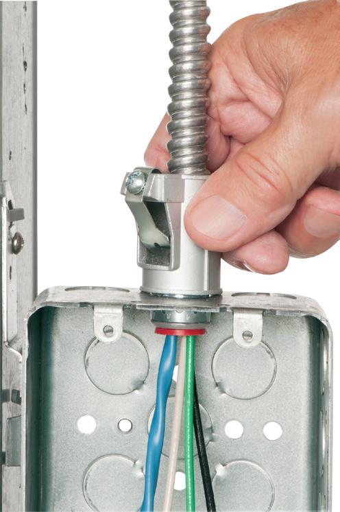
Fully assembled, SNAP2IT® fittings handle the widest variety of MC cable AND THE NEW MC-PCS cables.

Compared to fittings with a locknut and screw, you can’t beat these snap in connectors for time-savings!
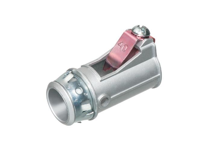


LISTED SNAP2IT ® CONNECTORS FOR NEW MC-PCS CABLE ...lighting & low voltage circuits in the same cable


• Fits widest range and variety of MC cable 14/2 to 3/3
AC, MC, HCF, MC continuous corrugated aluminum cable and MCI-A cables (steel and aluminum)...including the new MC-PCS cable that combines power and low voltage in the same MC cable
ANY Snap2It Connectors LISTED for MC cable are also LISTED for MC-PCS cable! These products offer the greatest time-savings.
• Fast, secure snap-on installation
• Easy to remove, reusable connector From cable Loosen screw on top. Remove connector from cable. From box Slip screwdriver under notch in Snap-Tite® Remove connector.


By Mose Ramieh III, CBS Field Services
Electrical power systems are often built with crucial auxiliary systems, which are often dependent on each other to ensure these power users have systems that are safe and reliable. The DC battery system might be one of the more significant of these systems.
DC batteries provide power to protective relays, breaker trip circuits, and other vital system-control systems. If these battery systems are not properly maintained and monitored, the safe operation of the entire power system will be placed in jeopardy.
When planning for DC battery system preventive maintenance, reference the ANSI/NETA Standards for Maintenance Testing Specifications for Electrical Equipment and Systems, Section 7.18.1 – 7.18.3. The specifications provide detailed recommended visual/mechanical inspections and electrical tests for batteries, chargers, and rectifiers.


Arlington’s steel SliderBar™ offers the easy, NEAT way to mount single or two-gang boxes between wood or metal studs with non-standard stud cavities.
No more cutting, nailing and fitting extra 2x4s to fill the space! SliderBar saves about 20 minutes per box. Designed for studs spaced 12” to 18” apart, SL18 allows positioning of one or more boxes anywhere in the stud cavity.
• Bending guides on bracket assure proper positioning on studs
• Interlocking tab stop prevents accidental disassembly


• Pre-punched pilot holes on BOTH sides of S for easy attachment of one or two boxes


Electrical Testing Education articles are provided by the InterNational Electrical Testing Association (NETA), www.NETAworld.org. NETA was formed in 1972 to establish uniform testing procedures for electrical equipment and systems. Today the association accredits electrical testing companies; certifies electrical testing technicians; publishes the ANSI/NETA Standards for Acceptance Testing, Maintenance Testing, Commissioning, and the Certification of Electrical Test Technicians; and provides training through its annual conferences (PowerTest and EPIC — Electrical Power Innovations Conference) and its expansive library of educational resources.
Deficient battery string conditions occur most commonly when a battery system is placed behind doors or covers.
One manufacturing facility suffered a catastrophic failure of its switchgear because of a loss of control power — the loss of control power to the medium-voltage switchgear created a situation where the electromechanical protective relays operated during an overcurrent condition in the system, but there was no DC control power to trip the breakers. This inability to trip the breakers allowed the fault to persist, doing more damage, until the fault was finally cleared by the upstream electric utility fuses.
The battery system had been overlooked for years because it was located in the rear of the switchgear behind a bolted cover. Photo 1 on page 26 shows the battery system with the cover removed.
While this is an odd place to locate the battery system, it is not entirely rare. The equipment lineup in Photo 2 also hides a battery system.
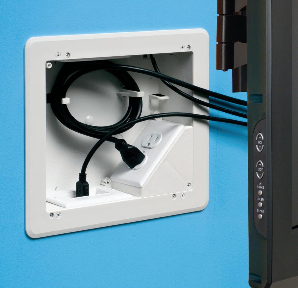
Arlington’s 8X10 TV Box™ with a Plastic or Steel Box offers the ultimate in versatility for installing TVs in new and retrofit projects. There's more room in the box for wires and it installs horizontally or vertically to properly position low voltage connections behind the TV.
• Ideal for home theater systems: multiple connections for sound systems, satellite TV, CATV, DVRs
• Brackets for neater cables, with a 1-1/2" knockout for ENT and other low voltage wiring


• Box mounts to stud in new work; for retrofit, mounting wing screws secure


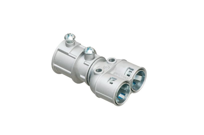
Arlington’s new duplex diecast couplings save time and easy transitions from 3/4" EMT to 3/8" trade size flexible metal cables – perfect for running MC cable above a drop ceiling and connecting EMT to feed a box or switch.
combination couplings install easily on AC, MCI-A, HCF steel and aluminum cable, flexible metal conduit (steel and aluminum, regular and reduced wall), MCI cable and continuous corrugated aluminum. And offer independent securing of different size cables.
• Tested, LISTED to exceed UL ground fault requirements Compatible with 3/4" EMT
SADDLE GRIP® styles

The best solution is to place battery systems where they are visible during a standard system walk-through. In utility substations, these battery strings are typically located on the floor of the substation control room and are completely visible so that even minor issues can be observed ( Photo 3 on page 28).
Getting back to our failure at a manufacturing facility example, there were visible warning signs that the DC control power had failed. Unfortunately, those responsible for monitoring the power systems were not familiar enough to recognize the warning signs. You might be guilty of this too if you have ever ignored a breaker with a red (breaker closed) light that is not illuminated. This could indicate something as simple as a blown lamp, but it could also be something as critical as a bad trip coil or a complete loss of control power — as was the case in this example.
Photo 4 illustrates the worst case of battery corrosion. This situation clearly indicates the power system was neglected with no service or inspection for many years.
The facility lacked the trained personnel necessary to ensure the system was properly maintained. This neglected system was discovered in response to flood recovery efforts. If not for a flood, this power system’s negligence would have likely continued.
All power system safety and reliability programs start with good housekeeping. When it comes to DC battery systems, a great deal can be learned — and issues can be avoided — from routine visual inspections. These are the items you should focus on:
• General corrosion on battery posts.
• Other cracked or damaged internals such as a cracked internal seal (Photo 5).
• Acid levels not between the high and low marks (Photo 5).
• Damage to plates including positive plate growth.
• Bright lead-sulfate crystals on the negative plates indicate the battery is being undercharged.


Designed for new construction, Arlington’s non-metallic FR series device and fixture boxes mount directly to a flat surface without the need to cut an opening in the substrate. They feature interchangeable backs and extension rings so ONE box works with almost any cladding system – including engineered foam/stucco systems.
Extra-wide flanges prevent water and air-intrusion, helping to meet the International Energy Conservation Code, and eliminating the need for gaskets or caulking.
• FR series boxes ship ready for use with 1-3/8” finish or cladding thickness Depth can be set for custom depth finishes or cladding materials up to 1-7/8"
• Install before or after the weather barrier house wrap - Installation of box before the house wrap at right
• 20 cu inch volume


Inspect the battery (particularly the bottom) for material that could eventually cause a short between plates.
An electric utility was making a system modification that necessitated de-energizing the control power transformer. “No problem, right?” they said. “Our substation doesn’t need AC power except for lighting and air conditioning in the relay control house.” Of course, this also created a loss of AC power to the battery charger.
During a short window — from a few hours to even as much as a couple of days — this is not an issue. However, the lack of a charging current causes the battery string to be slowly depleted. In this particular case, the slow depletion of the batteries created a DC undervoltage condition that led to protective devices tripping and knocking the entire substation offline. This interrupted power to thousands of customers. Recovery efforts included having to bring in a portable generator to power the charger as well as relays to be reset and breakers closed.
Most power system designs include DC battery-voltage monitoring by the protective relays. Those same systems will also trip breakers before the DC control power becomes too low to protect the system from being in a configuration where the breakers wouldn’t be able to trip.
Modern communication technology can be utilized to provide early warning for this type of system issue. In this example, a text message to the substation supervisor would have allowed an intervention to avoid the system tripping itself offline.
Additional inspections and testing that can be performed vary from easy to difficult. Here are some to keep in mind.
1. Note any indicator lights on the battery charger that represent a fault condition and/or error codes on a display. Avoid normalizing deviation and maintain an error code and fault-free system. Positive/negative DC grounds are one example of errors that can be difficult to resolve. Troubleshooting this type of error takes time and the ability to isolate portions of the system to locate and correct the ground.
2. Measure the voltage of the entire battery string with the charger DC output breaker off.
3. Measure the voltage of each half of the battery string. This value should be roughly half of the measurement of the entire string. Any significant variation should be investigated by measuring the voltage of each cell (which is also an option; it just takes longer).
4. Measure the charger output for AC ripple. Excessive AC ripple can shorten battery life by creating a situation where the battery is repeatedly undercharged and discharged.
a. One battery manufacturer recommends that a maximum ripple of 1.5% of the voltage be allowed during the bulk phase of the charging and a maximum of 0.5% voltage ripple during the float phase.
b. Remember to check battery charger manufacture

literature for ripple levels. The nameplate in Photo 6 lists the design ripple as 100mV rms.
5. Float and equalize charger settings. Settings that are too low or too high will damage the batteries and shorten their service life.
6. Check the specific gravity level of the batteries.
7. Perform a load bank test.
Remember to always use the appropriate personal protective equipment (PPE) when working on and around batteries. Ensure that eye wash stations are available and working (the water tank is full and/or water is available to the system). Use insulated tools when working on a battery system. Wrapping a wrench or screwdriver with electrical tape does not make it an insulated tool.
Mose Ramieh III is vice president, business development at CBS Field Services and has been in the electrical testing industry for 26 years. Over the years, he has held various positions including field service technician, operations, sales, business development, and company owner across four companies.

Arlington’s Concrete Pipe Sleeves are the economical way to sleeve through concrete pours in tilt-up construction WALLS – and FLOORS allowing cable and conduit to run easily from one floor to the next.
No costly core drilling – No cutting holes in the form. Plus, you can position the hole prior to pouring the concrete.
• Attaches to form with nails or screws
• Stackable up to 23" h for extra deep pours
• Vents keep wet pipe sleeves from sticking together
• Multiple hole sizes: 1-1/2"


Arlington’s new one-piece RETROFIT SNAP2IT® fittings are easy to use in an OLD WORK installation, and handle the widest variety of cables! They’re ideal for adding additional circuits to a load center. And you get the same labor-savings in a retrofit installation!
Easy snap-in installation - NO TOOLS. Install connector into the knockout in an existing box, pulling cable/conduit through the knockout. Slip the fitting onto the cable, then snap the assembly into the box. That’s it... a secure installation with no pullout

Widest total cable ranges 14/2 to 10/3
Widest variety of cables AC, MC, HCF, MC continuous corrugated aluminum cable, MCI-A cables (steel and aluminum), AC90,


The multi-wire branch is here to stay; so is ground-fault protection. But we should unite these technologies only when it’s a good match.

By Randal Andress, Electrical Engineer (retired from Northrop Grumman)
Ground-fault protection and the multi-wire branch circuit (MWBC) are both common topics in the electrical industry. This article discusses their union — the use of a 2-pole GFCI/GFPE breaker to protect the two 120V legs (L1 and L2) of a 120V/240V split-phase, 3-wire (L1/ L2/N), shared neutral circuit. You may be surprised (as I was) to find that the protection provided is attended with subtle (if not troublesome and problematic) differences from the protection provided by a single-pole breaker on a 2-wire circuit (hot/neutral). The manifestation of these differences in a marine environment is of particular interest and will be highlighted in this piece. Several years ago, I began thinking about the effects of marina basin background current (sometimes called foreign or stray current) on the measurement of AC leakage from boats — as is commonly made by clamping the shore power cord with an ammeter. I concluded that the effect of background current depends on whether it originates from the same or opposite leg (L1/L2) of the distribution source as the current leaking from the boat circuit.
That led to the question of how fault/leaks from different legs of a main or feeder panel would be seen by a 2-pole (L1/L2/N) ground-fault protection breaker. So far, I have been unable to locate a treatment of this subject. (Perhaps readers will be able to provide me with references.) So based on my analysis, simulation, and testing as well as interaction with a few electrical professionals, I have reached preliminary conclusions. They are presented in this article with the expectation that they will elicit

Arlington’s recessed STEEL combination power/low voltage TV BOX™ is the best way to mount an LED or Hi-Def TV flush against a wall.
TV BOX provides power and/or low voltage in one or more of the openings. Plugs and connectors stay inside the box, without extending past the wall.

Designed for use in new or retrofit commercial construction where metal raceway is used, we have a STEEL TV BOX for almost any application!


• Steel box; non-metallic paintable white trim plate
• Easy, secure installation
• Optional covers


ROOF TOPPER® supports raise conduit/raceway 4" or more off the roof surface, allowing contractors to comply with the 2017 NEC® for temperature adjustment for circular conduit.
The heavy-duty base, made of 100% recycled material, sits on the roof deck. There’s no need to mount ROOF TOPPER to the surface with mechanical fasteners.


Offered in a variety of sizes and configurations, ROOF TOPPER supports up to 2000 lbs, and stands up to extreme rooftop conditions protecting and elevating conduit or raceway above the roof deck.


comments, critique, and reader feedback from the EC&M audience.
Before considering the 2-pole groundfault protection breaker on an MWBC, let’s look briefly at the single-pole, 2-wire (H/N), GFCI/GFPE breaker (Fig. 1). Its heart is the residual current transformer (CT). The core of the transformer is typically a toroid — a doughnut-shaped ring of magnetic material (the heavy black ring in Fig. 1). Both the hot and neutral conductors are passed through the toroid, making each of these conductors a single-turn primary winding of the CT.
The transformer’s secondary is a multi-turn winding on the toroid that functions as a sensor. It is energized when the sum of the currents in the hot and neutral primaries is non-zero. Consider current flowing through the toroid on the hot or neutral from the source toward the load to have one sign (+ or -) and current flowing in the other direction to have the opposite sign (- or +, respectively). If the current that flows from the source out on the hot wire is equal to that returning through the neutral, then a net-zero primary current results — so no magnetic
field is generated; therefore, no current flows in the secondary winding. This is the case when the circuit has no leaks or faults to ground.
On the other hand, if some of the cur rent returns to the source — not on the neutral but on the safety ground or through some environmental path — (e.g., a person, a building structure, and the earth), then there is a current imbalance. The neutral return current will be less than the hot supply current. These unequal, opposite direction hot and neutral currents do not offset each other. The result is a non-zero net cur rent through the primary windings that produces a magnetic field whose AC dynamics induce a current in the sens ing secondary winding — a current that is proportional to the imbalanced cur rent sum. If the imbalance reaches the trip level for the breaker (e.g., 5mA for a GFCI and 20, 30, or 100mA for a GFPE), then the breaker is tripped by processing circuitry, which opens the hot conduc tor path.
To be able to periodically test its functionality, a GFCI/GFPE breaker is equipped with a manual test circuit. A push-button switch completes a path from the load side hot through a resis tor to the supply side neutral, thereby providing a return path for a test current

• All normal currents flow out on Hot (H) and return on Neutral (N) producing a zero current sum in the CT primary and no current in the sensing secondary.
Fault/leak current flows out on Hot through the current summing transformer and returns on the Gnd without any offsetting current on Neutral.
• This imbalanced net flow in the CT primary (fault/leak current) creates a magentic field which generates a non-zero current in the current summing secondary.

Normal current to load returning on neutral
Fault/leak current returning on ground
Current in CT secondary due to H/N imbalance
No connection
Connection
Fig. 1. Ground-fault protection of a single 120V branch circuit using a single-pole ground fault protection (GFP) breaker.


Perfect for EV Chargers in parking garages, panels, equipment feeds and data center remote power panel feeds, Arlington’s Listed CableStop™ Transition Fittings deliver the efficient, cost-effective way to transition feeder cables to 2-1/2" EMT, IMC and RMC conduit in protective drops, risers and feeds to panels and equipment.
Our new CableStop fittings integrate our patented, versatile and SKU-reducing 8412 series cable fittings, with Arlington conduit fittings, allowing for easy transitions to larger knockout sizes.
Available with set-screw or compression connections into 2-1/2" conduit, they ship with multiple end-stop bushings that vary the size of the opening –along with a to help installers select the right bushing for the cable.


2" Trade Size • 2-1/2" Conduit size
Listed for EMT, IMC, RMC conduit 841516 Set Screw connection


that does not flow through the toroid. The imbalance created simulates an actual fault or leak. Since the resistor is chosen so that the current is just above the trip limit, the breaker trips in the usual way. Typically, this test is to be performed monthly.
Now let’s consider the subject circuit: a 120V/240V multi-wire branch protected by a 2-pole (L1/L2/N) GFCI/ GFPE breaker ( Fig. 2 ). A second ungrounded conductor (red in Fig. 2) is added to the single-pole breaker current transformer as a third primary. This conductor originates on the opposite leg (line or split-phase) of the single-phase service source. It takes a switched path through the breaker and passes through the CT toroid to a loadside connector. From there, it is wired to a separate 120V circuit (L2), but it uses the same neutral as a return path. Normal load current flows out L1 hot or L2 hot to the load and returns on L2 hot or L1 hot, respectively, or on the neutral. The current on the neutral is the difference between the L1 and L2 currents [iN = | iL1 – iL2 |]. An L1 fault or leak to ground (red zigzag in Fig. 2) flows through the current summing transformer (on L1) without any offsetting current in L2 or N. Just as in the single-pole breaker, this imbalanced net flow in the primaries creates a magnetic field that generates a nonzero current in the current summing secondary, and the breaker trips at the designed trip current level.
That explains the case of a fault/leak on one leg (L1) or the other (L2). But suppose there are fault/leaks on both the L1 and the L2 120V branch circuits. First, consider the case of equal fault/leaks (Fig. 3 on page 40).
The current flow for equal fault/leaks is similar to that of equal loads (L1 and L2) — the return current for each uses the opposite leg. Follow the L1 fault/leak current (orange arrow in Fig. 3) from the L1 source through the CT out to the L1 leg fault. It flows to ground through the L1 fault path and then through the L2

•
• L1 Hot fault/leak to ground flows through the CT without any offsetting current in L2 Hot or N.
• This imbalanced net flow in the CT primary (|L1- L2|fault/leak current difference) creates a magnetic field which generates a current in the CT current sum sensing secondary.
Normal load current during 2nd half cycle
Fault current direction during 1st half cycle
Fault current direction during 2nd half cycle
Secondary current generated by primary imbal.
Fault/leak current from L1 Hot
No connection Connection
Fig. 2. Ground-fault protection of a multi-wire branch circuit using a 2-pole GFP breaker when only one leg (L1) has a fault/leak.
fault to L2 and returns on L2 through the CT to the source. So no current returns on the ground or the neutral. The current that flows from L1 returns in L2 and vice versa. The current sum in the CT primaries is zero; therefore, there is no magnetic field, no current in the secondary, and no trip. Note that regardless of the size of the fault/leaks, if they are equal, the breaker will not trip.
But suppose one leak is smaller than the other (Fig. 4 on page 42). Let’s say the 2-pole breaker is a GFPE with a 30mA trip limit. Suppose the appliances connected to L1 have a total fault/leak current of 25mA, and the L2 total is 15mA.
Normal currents (not fault/leaks) flow to and from the load on the L1/ L2/N as usual; therefore, they will flow in equal amounts in both directions through the CT and will not contribute to any current imbalance measured by the secondary. They are being ignored in this analysis.
Let’s trace the fault/leak currents on the positive AC half-cycle (i.e., when the instantaneous L1 voltage is greater than the L2 voltage. See the orange arrows in
Fig. 4). The L1 current, 25mA, travels from the source through the CT to the fault/leaks and then through them to ground. At the ground point, 15mA of the 25mA travels through the L2 fault/ leakage path to the L2 circuit and returns through the CT to the source on the L2 circuit. The remaining 10mA follows the ground path back to the source via the panel ground to neutral bus connection. During the negative half-cycle, the currents all reverse on the same paths and in the same amounts. (The negative halfcycle is not shown in Fig. 4; they would be blue arrows equal in size and head to head with each orange arrow.)
The current imbalance in the CT primaries is: 25mA L1 source to load (+), 15mA L2 load to source (-) and 0mA through the neutral, 25mA + (-15 mA) + 0 = 10mA. The resulting magnetic field induces a current in the secondary indicative of a 10mA imbalance so the breaker will not trip (10mA < the trip level of 30mA).
Let’s look at another case. With L1 still faulting/leaking at 25mA, suppose L2


the cable into the connector and rotate the connector clockwise.

YEARS
Available in 3/8" trade size, both connectors install into a 1/2" knockout, and are Listed for steel and aluminum AC, HCF, MCI and MCI-A cable.
The tinted 40STS has more room inside for easier cable insertion.
for use with AC90 and ACG90 cable.
• Tested to UL 514B and Listed to meet UL ground fault requirements
• Removable Unscrew the connector counterclockwise to remove it from the cable. Remove the connector from the box using a flat blade screw driver. Release the snap tangs from the inside of the box while pulling the connector out of the knockout.
• Packed in heavy-duty, 200-piece boxes
CATALOG NUMBER CABLE RANGES STEEL Snap2It® connectors
38STSC AC, HCF, MCI, MC!-A 14/2 w ground, 14/3, 14/2 12/2 w ground, 12/3, 12/2 • 10/2 w ground, 10/3, 10/2 .405” Dia. Minimum to .605” Dia. Maximum
40STSC AC, HCF, MCI, MC!-A Tinted 12/2 w ground, 12/3, 12/2 • 10/2 w ground, 10/3, 10/2 .480” Dia. Minimum to .605” Dia. Maximum

All normal current (not shown) flows out L1 Hot or L2 Hot and returns on L2 Hot or L1 Hot, respectively, or on the Neutral without creating a CT current imbalance. If equal, L1 and L2 fault/leak currents return through the series connected fault/leak in the opposite leg (not on the Neutral, the Gnd, or the earth).
• The current sum through the CT primary is zero so the magnetic field is zero and the current in CT secondary sensing winding is zero.
Current direction during 1st half cycle
Fault/leak current from L1 Hot
Fault/leak current from L2 Hot
Fig. 3. Failure of a 2-pole GFP breaker to detect equal ground fault/leaks when present on both legs (L1 and L2) of a multi-wire branch circuit.
gets an additional 35mA fault (5mA over the 30mA trip limit) — bringing its total fault/leak to 50mA (15mA + 35mA). Using an analysis similar to the above, we can trace the fault/leak currents but use the negative AC halfcycle this time. The 50mA L2 current flows from the source on L2 through the CT toward the load but takes a fault path to ground. From there, it splits — 25mA takes the L1 fault/leakage path to the L1 circuit and returns through the CT on the L1 conductor. The remaining 25mA returns through the ground to the neutral bar in the panel. With a 50mA source to load on L2 and a 25mA load to source on L1, the CT imbalance is 25mA detected by the secondary. But that is still 5mA short of the required 30mA to trip. So with 75mA flowing through faulting/leaking paths, 25mA on L1, and 50mA on L2, the 30mA breaker still will not trip.
Looking closer, there’s still more confusion. Suppose that 20mA of the 25mA L1 fault/leak is due to a fault in a single appliance. If this faulty appliance is removed, the L1 fault/leakage drops to
5mA, the imbalance increases to 45mA (50mA L2 – 5mA L1 = 45mA > 30mA), and the breaker trips.
If we reconnect the faulting appliance and reset the breaker, it does not trip because the imbalance goes back down to 25mA.
One of the most troublesome and unhelpful consequences of 2-pole ground-fault protection of an MWBC is the effect on the push-to-test feature (Fig. 5 on page 44). As described earlier, the test button produces a current imbalance just above the trip limit. Let’s suppose in the case of our 30mA trip example GFPE, the test circuit draws 31mA from L1 (shown in Fig. 5 by large orange arrows circled in black).
Provided there is no leak or fault on L2, the breaker will trip when the test button is pressed since the entire 31mA will be an imbalance. But if there is a leak or fault on L2 (shown in Fig. 5 by mid-sized orange arrows circled in red), a portion of the test current flows through the neutral-ground connection in the panel, through the L2 fault/ leak and onto the load side of L2, and
then back through the CT to the source, thus reducing the 31mA imbalance by the amount of the L2 leak. If the L2 leak is more than 1 or 2mA, the test button imbalance will not be enough to trip the breaker (31mA - 2mA < 30mA). Unless L2 is essentially free of fault/leaks, the push to test button will misidentify a good breaker as faulty.
Let’s return to our continuing example and actuate the test button. After reconnecting the faulting appliance, L1 has 25mA of fault/leak current and L2 has 50mA. If the test button is pushed, ~31mA is added to the 25mA L1 leakage path, bringing the L1 total fault/leak up to 56mA. With L2 fault/leak current at 50mA, there is a 6mA imbalance, 56mA + (- 50mA) + 0mA = 6mA, which is less than the trip limit. The breaker does not trip, thus indicating a bad breaker. A good breaker fails the push button test.
Note how difficult this circuit would be to diagnose. If all appliances were removed, the breaker would test “good.” Then, as the devices are reconnected, the point at which the breaker would test bad, or trip (even if it would trip at all) would depend on the order of reconnection. If L2 were disconnected or all L2 loads removed (only L1 connected, 25mA fault/leak current), the breaker would not trip, and the test button would trip the breaker. If L1 were disconnected from the breaker or all L1 loads removed (only L2 connected, 50mA fault/leak current), the L2 fault/leaks themselves would trip the breaker. We could multiply similar examples of unnecessary confusion when trying to track down problems — confusion that would not exist if 120V circuits requiring ground-fault protection were provided their own neutral return rather than sharing a neutral with another circuit on a multi-wire branch. Before dismissing this musical connections scenario as unlikely, consider the marina where connecting and disconnecting boat shore power with varying and uncertain order is the norm.
In a nutshell, what we find is that when feeding an MWBC, the 2-pole
for


and UNTHREADED RIGID and IMC
Get convenience and time-savings with Arlington’s 550 series SPLIT grounding bushings. The split allows the addition of a bushing AFTER conductors are installed in threaded or unthreaded Rigid/IMC conduit. Great for tight spaces!
• In 1/2" to 4" trade sizes – Ships Assembled
• Compatible with EMT, 2-1/2" to 4" trade sizes, and threaded electrical fittings
1 Loosen side screws. Allow bushing to pivot around installed cables
2 Tighten set screw to seat bushing on conduit EASY TO INSTALL


1


2
aifittings.com/landing/split-grounding-bushings
In a tight spot? Arlington’s new SNAP-TITE® Transition Fitting offers the time-saving solution for installing additional conduit or cable in an already congested panel.
It allows installers to work around tightly spaced, installed fittings in a panel, box or enclosure
– where installing and tightening additional locknut fittings would be next to impossible.

Convenient, Time-Saving 2450ST snaps into a 1/2" knockout and connects 1/2" trade size threaded fittings or pipe.


ground-fault protection breaker trips when the imbalance caused by the difference in the L1 vs. L2 fault/leaks exceeds the trip limit. In other words, it trips when:
|(L1 leaks & faults) – (L2 leaks & faults) | > Trip Limit.
It is incapable of tripping on an L1 fault at the trip limit unless the leakage and fault current of L2 is equal to or less than that of the pre-fault L1 circuit. For the faults or leaks on one leg (L1) to cause a trip, they must exceed the total faults and leaks on the other leg (L2) by at least the trip limit.
To put it another way, the common multi-wire branch circuit cannot be protected against ground faults to the same degree and with the same precision, the same measures of protection, consistency, and expectation of behavior, etc., as a branch with its own neutral. This is not all that surprising when you consider that by sharing a neutral, the return current of each branch is made anonymous as to its origin (L1 vs. L2).
Here are some of the effects of using a 2-pole ground-fault protection breaker on an MWBC:
• Fault current on one leg above the rated ground-fault protection level is required to trip the breaker in the presence of a fault/leakage current on the other leg, thus decreasing fault detection sensitivity.
• The manual test button will not reliably perform a valid test. A good breaker will test bad when L2 fault/ leakage current is greater than that of L1 (plus test current margin) or when L1 fault/leakage current is greater than that of L2 (plus margin), depending on whether or not the current for the test button is drawn from L1 or L2, respectively.
• L1 and L2 circuits may be able to sustain leakage/fault currents well above the rated ground fault protection level. That is, fault/leaks may be arbitrarily high without tripping the breaker so long as their fault/leakage difference (L1 vs. L2) is less than the rated groundfault protection level. For example, a faulty/leaky boat, which trips the feeder’s 2-pole GFCI/GFPE when connected to an L1 120V/30A circuit, could work just fine without tripping if moved to
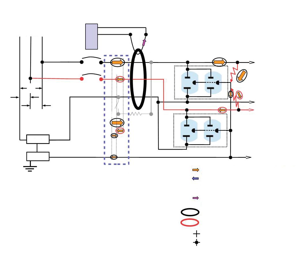
• If fault/leak currents are not equal, e.g. L1 fault/leak > L2, the part of the greater (L1) that is equal to the lesser (L2) returns through the series connected fault/leak in the opposite leg (L2) and in the opposite direction through the CT creating a current imbalance. The remainder of the greater (L1) fault/leak current returns through the ground and not back through the CT.
• The imbalance is equal to the difference between the L1 fault/leak and the L2 fault/leak and induces a proportional current in the CT sensing secondary.
Current direction during 1st half cycle
Current direction during 2nd half cycle — not shown but equal and opposite to orange arrows
Secondary current generated by primary imbalance
Fault/leak current from L1 Hot
Fault/leak current from L2 Hot
No connection Connection
Fig. 4. Failure of a 2-pole GFP breaker to detect a fault/leak on one leg (L1) that is in excess of the trip limit on a multi-wire branch circuit in the presence of a smaller fault/ leak on the other leg (L2).
an adjacent L2-powered receptacle. If, when moved to L2, the L2 fault/leaks are now greater than those of L1, then the fault/leaks of the next boat to connect to an L2-powered receptacle could cause a trip. But likewise, it could then be moved to L1, and so on. So long as the difference in fault/leaks between L1 and L2 remains below the trip limit, faulty/ leaky boats could continue to be added, increasing the total fault/leakage current flowing through the GFPE device into the water.
• The removal of an appliance or device from a circuit could cause a trip. This happens when the fault/leak in the removed device is of such value that, when removed, it increases the L1 vs. L2 difference up to the trip level. The order of appliance connection and disconnection determines the possible, trip/ non-trip, circuit states.
These effects apply to virtually every 120V multi-wire branch that consists of a grounded neutral conductor and two ungrounded conductors from opposite
legs (L1 and L2) of the 240V split-phase source. However, the implications in some cases are decidedly more significant than in others.
On the less troublesome end of the spectrum might be the dishwasher and garbage disposal split duplex receptacle that is fed by a 2-pole Type A GFCI breaker (where permitted by applicable codes). In the first place, the Class A GFCI trip point is low (~5mA), so the test button dead zone (where good breakers will test bad) for a test current of 7mA would be only about 3mA wide (i.e., for fault/leak differences of greater than about 2mA and less than 5mA). Also, there is only one appliance connected to either leg (L1/L2), there are no available additional receptacles, and the two that do exist are typically not conveniently accessible to be subject to change. Lastly, but perhaps most importantly, both the wiring and the appliances are subject to mandatory standards and codes.
At the more troublesome end might be a 2-pole (L1/L2/N) 100mA GFPE multi-wire branch circuit at a marina

Captive screws attach bracket ends to joists


Arlington’s heavy-duty, plated steel fan/ fixture box has an adjustable bracket that mounts securely between joists spaced 16" to 24" o.c.
Flush ceiling installations

FBRS415 is designed for ceilings up to 1-1/4" thick. For 1/2" ceilings, use the pre-bent positioning tab. For other ceiling thicknesses, bend along the appropriate score line.
• 15.6 cu. inch box ships with captive screws, mud cover, installed NM cable connector


that supplies 120V/240V as well as both L1 and L2 120V to shore power pedestals which could contain 2-pole 30mA GFPE feeding 120V/240V shore power receptacles. The circuits’ connected loads (i.e., the boats) vary widely both as to the mix of appliances and devices onboard and also with time (here today, gone tonight, in a different slip tomorrow) and are not subject to mandatory codes. In addition, the circuit fault/leaks could exceed a safe limit and could be flowing through persons or animals in the water.
GFCI/GFPE breakers are the focus of this article, but what other devices might be subject to some of these same effects when used on shared neutral circuits (L1/L2/N)? Any of the alphabet soup of residual current devices (RCDs) that provide ground-fault protection is suspect.
For example, the ELCI used onboard boats that is called for in the American Boat and Yacht Council (ABYC) E-11 standard is another ground-fault protection device that uses residual current detection. Those that provide 3-wire 120V/240V (L1/L2/N) multi-wire branch protection are subject to these same issues.
What about the arc fault circuit interrupter (AFCI)? If some AFCI breakers use residual detection as a component of its functionality, then perhaps a 2-pole (L1/L2/N) AFCI feeding a multi-wire branch circuit could be subject to some of the same problematic behaviors as are GFCI/GFPE devices depending on its implementation. This needs further study.
The question is, for circuits requiring ground-fault protection (personnel or equipment), do the savings of the MWBC justify the additional safety and usability costs? And secondly, although not secondarily, are these safety and usability costs sufficiently understood by those who design, construct, and maintain them?
Each of us operates in our own sphere of activity and influence, whether that be standards and code-making, engineering, construction, maintenance,

• The direction of L2 fault/leak current is opposite to that of L1 test current during the 1st half-cycle.
The test current that flows from L1 that would otherwise produce an imbalance just over the trip limit is offset by any fault/leaks in the opposite line (L2).
• If the L2 fault/leak is greater than the test current minus the trip limit, then the imbalance is reduced to a value below the trip limit and the breaker will not trip when tested.
Current direction during 1st half cycle
Secondary current generated by primary imbalance
Test current from L1 Hot Fault/leak current from L2 Hot
No connection
Connection
Fig. 5. Push-to-test of a 2-pole GFP beaker can misidentify a good breaker as faulty.
or property owner. We should all look for ways to combat the confusion and problems of the GFCI/GFPE-MWBC union. Some ways in which we can do this might include:
• Advance the awareness and understanding of this behavior in forums, presentations, publications, and continuing education.
• Consider limiting the use of a 2-pole GFP device on an MWBC for ground-fault protection of 120V circuits to small, well defined, or stable circuits with small numbers of appliances and few, if any, open receptacles (sockets), such as for garbage disposals and dishwashers using a split duplex receptacle.
• Minimize their use at docks, marinas, boathouses, and aboard boats. Where permitted and feasible at docks and marinas, provide ground-fault protected 120V L1 and L2 feeder circuits to carry 120V service to the pedestal rather than drawing it from a 120/240V MWBC circuit in or near the pedestal. By doing this, the only circuits subject to the limitations of the 2-pole GFP device will be those boats that connect to 120V/240V shore cords.
• Aboard boats, provide single-pole GFP devices to protect 120V circuits that
are supplied by a 120/240V shore cord — even those connected through an ELCI (L1/L2/N/).
• Most ill effects of offsetting fault/ leaks may be substantially reduced by feeding L1 and L2 with two phases of 3-phase 208Y/120V service. Any two phases differ by 120 degrees, whereas the two legs of 240/120V split-phase service, the subject of this article, are directly opposed (differ by 180 degrees). It can be shown that an L1 to ground fault/leak will only increase the L2 fault/ leak current required to trip by at most about 15%. For example, a GFPE with a nominal 100mA trip limit would require at most about 115mA (nominal) to trip in the presence of an existing fault on the other leg. For environments such as boatyards and marinas where fault/leaks are likely and are especially dangerous, this advantage of 208Y/120V service should be considered.

Randal Andress holds a B.S. in Electrical Engineering and is retired from Northrop Grumman. He is a Vietnam era veteran (USAF) and is a member of NFPA and the Electric Shock Drowning Prevention Association. He can be reached at randalpandress@gmail.com.


(SEE ABOVE)

• Easy snap-in cable installation Save time over 90° 2-screw MC Connectors at same cost per connector
• Handles widest range & variety of cables: 14/2 to 10/2 AC, MC, HCF, MC continuous corrugated aluminum cable, MCI-A cables (steel & aluminum), AC90 and ACG90
• Fast, secure installation...No pullout
• Easy to remove from box...reusable

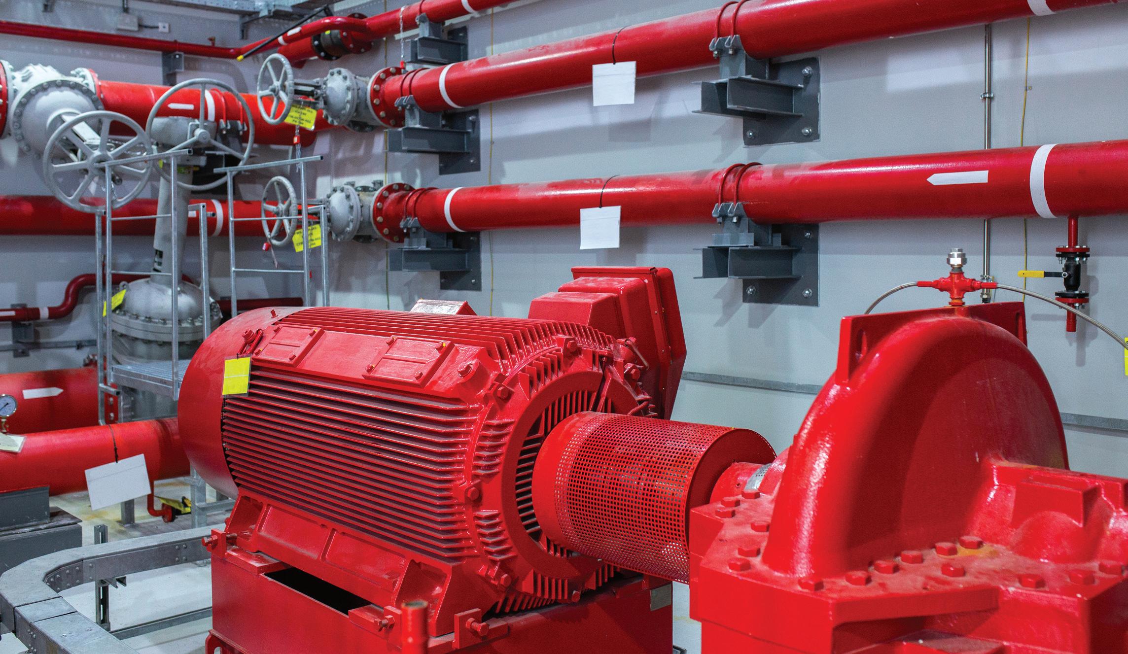
One of the most misinterpreted and misapplied NEC requirements in the electrical industry is power service to electric fire pumps.
By Brian E. Smith, The Engineering Enterprise
In my consulting business, I have the opportunity to peer review construction documents prepared by other electrical engineering firms. In doing so, I find it astounding how many times I comment on the fire pump service not being in conformance with Code requirements. This common problem should never occur due to the critical nature of a fire pump’s function.
Some of the more common non-Code-compliant applications I see are:
• Fire pump disconnects in the same lineup as the main service disconnect and other distribution breakers.
• Fire pumps fed from the meter/main disconnect located on the opposite side of the electric utility pull section from that of the building meter/main disconnect.
• Fire pumps tapped downstream of the building main disconnect.
• Fire pumps served from alternate source generators with disconnects not grouped in vertical section(s) for emergency loads [National Electrical Code (NEC) Art. 700].
• Improper survivability applied to fire pump feeders and/ or service conductors.
This situation is so prevalent in the industry that I see it

Arlington’s economical CUS6 galvanized steel Cable Support holds cable secure and centered on a metal or wood stud.
It’s perfect for fastening and individual metal clad cables –or six NM cables on a 2x4. to a wood or metal stud, and position the cables. Next bend the strap at the foldline (centerline). Fold the strap over the cables and insert the locking tab in the opening as shown to hold


Arlington’s mounting brackets are the best way to install Class 2 wiring. They seat wall plates flush with the mounting surface and install fast! Our new single gang, zinc mounting bracket, LV1M, for existing construction, offers extra rigidity so it won’t bend as easily as plastic. Plus, it has threaded holes for easy, fast device installation – and LABOR SAVINGS.
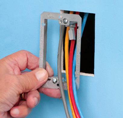


done wrong many more times than I see it done right. This series of articles, presented in three parts, offers design guidelines for electric fire pump power services. This first installment provides a summary of fire pump requirements (along with Code-related references in the NEC) to help assist electrical designers in their design process.
The idea behind the electric services to fire pumps is to maintain the operation of the pump for as long as possible under the worst possible conditions. The oversizing of the normal source overcurrent protective device at lock rotor current (approximately six times the rating of the motor) is to allow the motor to continue operating even in an overcurrent and/or overheating condition without the device tripping. This is the opposite approach of what the NEC requires for any other piece of equipment in a building — where the overcurrent protective device is there to protect both the equipment and conductors.
In earlier editions of the NEC, the reason for routing the conductors outside the buildings, or concrete encased within the building, was to protect the building from possible fire caused by the overheating of the conductors. The 2023 NEC implies the reason is to protect the conductors from conditions within a building, such as a fire.
However, both these conditions are met in the current NEC.
As per NEC Sec. 695.3 Power Source(s) for Electric Motor-Driven Fire Pumps, “Electric motor-driven fire pumps shall have a reliable source of power.”
I have never encountered a situation where the local inspector argued that the electric utility service was not considered reliable, but I assume it could happen. If so, you might want to consider using a diesel-driven fire pump in place of an electric-driven fire pump. The other option would require a generator as an alternate source of power to an electric fire pump with the primary source being electric utility power.
Assuming the electric utility source is reliable — and the building is not high-rise construction — the following would apply:
“NEC 695.3(A)(1) Electric Utility Service Connection. A fire pump shall be permitted to be supplied by a separate service, or from a connection located ahead of and not within the same cabinet, enclosure, vertical switchgear section, or vertical switchboard section as the service disconnecting means. The connection shall be located and arranged so as to minimize the possibility of damage by fire from within the premises and from exposing hazards. A
tap ahead of the service disconnecting means shall comply with 230.82(5). The service equipment shall comply with the labeling requirements in 230.2 and the location requirements in 230.72(B).”
The above allows three different approaches for serving a fire pump. The first approach is to have the electric utility company provide a separate service lateral for the fire pump. Because it is a service lateral, the electric utility company will include a grounded neutral conductor, along with the phase conductors, requiring termination in a switchboard with a neutral disconnect link. The fire pump service entrancerated switchboard will also include a utility meter and main disconnect device. The Code does not require the fire pump to have a disconnecting means, but most electric utility companies will. This approach would not be my first choice, as the electric utility company would generally tap the same utility transformer as the building’s permanent service to serve the fire pump, meaning two service laterals from the same source. It would also require a utility metering section and would be the most expensive of the three approaches. For an example of this approach, see Fig. 1.
You will notice Fig. 1 includes a jockey pump, also known as a pressure maintenance pump. The purpose of the jockey pump is to maintain constant pressure in the sprinkler system piping. This ensures that if a sprinkler head is

Arlington’s variety of cULus Listed Box Extenders extend set back electrical boxes up to 1-1/2”.
Made of heavy-duty, 105°C continuous use 94V0 rated, flame retardant plastic, they level and support wiring devices, while protecting wires against damage and stripping.


Choose the one that’s right for you!
BE1, BE2, BE3, BE4...Single-, two-, three- and four-gang, and BE1R for round or octagonal boxes...
Box Extenders


device support in oversized or mis-cut wall openings, available in single-, two-, three- and four-gang, (patented BE1X, BE2X, BE3X, BE4X.)
Our new heavy duty, COMMERCIAL-GRADE steel support plate! As shipped, the single gang BE1XLS works with maxi cover plates, but it’s Convenient. Saves time. Great for poorly cut drywall.

For all standard devices, switches and GFCIs, our box extenders comply with NEC Article 314.20 for set back boxes.


activated, the loss of pressure would be sensed at the fire pump controller, causing the fire pump to automatically start.
The second approach, very similar to the first, would have only one service lateral to the building and then tap the bussing in the utility pull section of the main switchboard, ahead of the utility meter and main disconnect device, for service to the fire pump switchboard. This is an extension of the service lateral, so the electric utility company
would again require termination of the grounded neutral conductor and neutral disconnect link in the fire pump switchboard. The fire pump service entrance-rated switchboard would also include a utility meter and main disconnect device. Of the three approaches, this would be the second most expensive. For an example of this approach, see Fig. 2
The third approach is my preferred method for fire pump services. It requires a vertical section of switchboard
(nominally 18 in. wide), between the utility meter section and the main disconnect section, where the switchboard bussing is tapped to serve the fire pump disconnect. In this case, only a fire pump disconnect is required because the tap occurs downstream of the utility meter. These tapped conductors shall meet the requirements for service-entrance conductors and include the grounded neutral conductor to the fire pump disconnect, where it should be bonded to
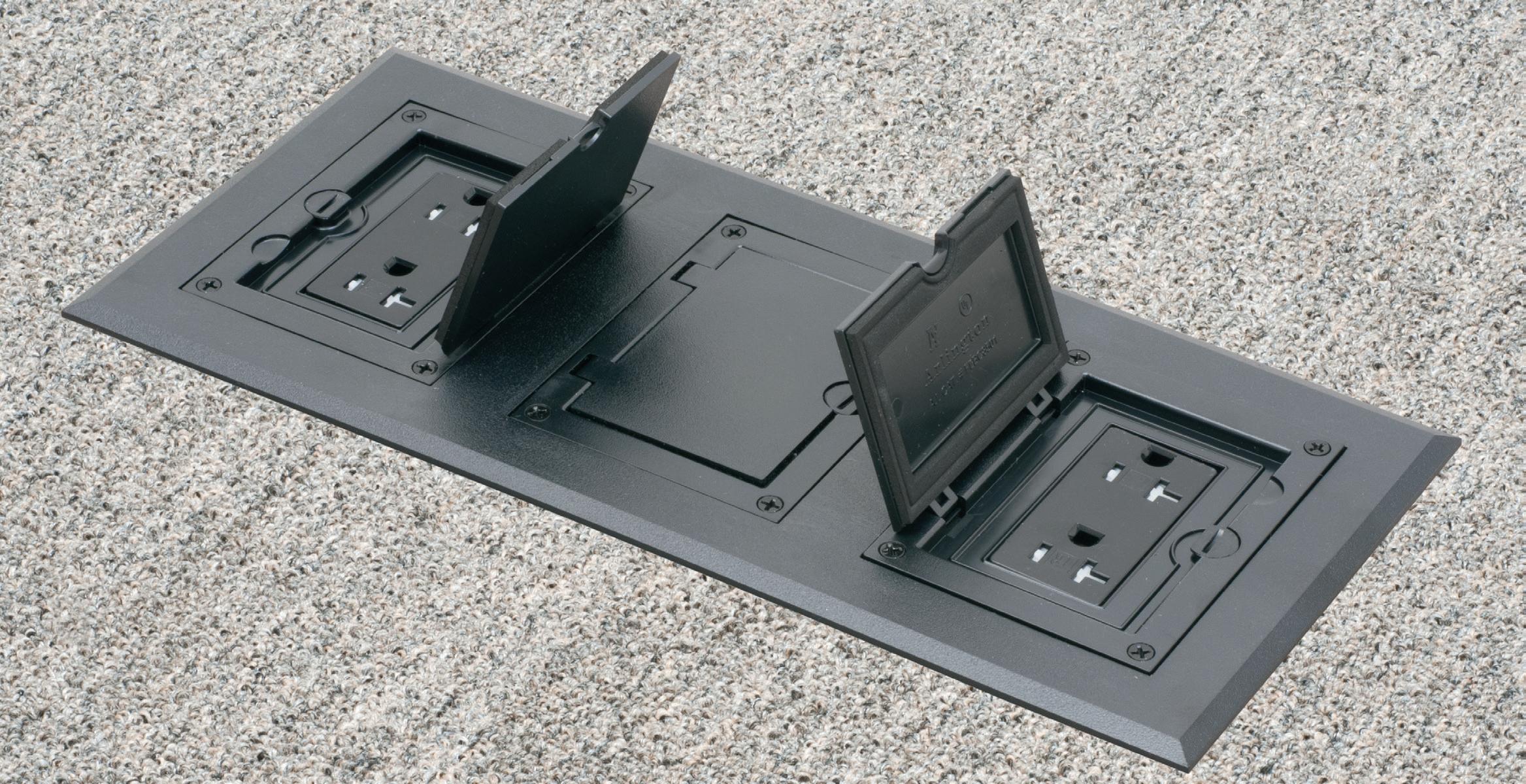


FLBC8500 Single gang box FLBC8500
(3) FLBC8500 boxes

Cover/frame kits


in USA Plastic Cover/frame Kit
Single gang
FLBC8510BR Brown
FLBC8510BL Black
FLBC8510GY Gray
FLBC8510CA Caramel
FLBC8510LA Lt Almond
Two-gang
FLBC8520BR Brown
FLBC8520BL Black
FLBC8520GY Gray
FLBC8520CA Caramel
FLBC8520LA Lt Almond

Three-gang
FLBC8530BR Brown
FLBC8530BL Black
FLBC8530GY Gray
FLBC8530CA Caramel
FLBC8530LA Lt Almond


a two-gang box. Add another for three-gang!

Build a two- or three-gang concrete floor box by simply locking single gang boxes together!
Then buy the UL LISTED single, two- or three-gang cover/frame kit, with devices included, in PLASTIC, FIVE COLORS – or in economical diecast zinc with a brass or nickel finish. Fast, easy installation.
Cover installs with hinge on either side.
Cover/frame Kit


Two-gang FLBC8520MB
Three-gang FLBC8530MB
Three-gang FLBC8530NL


This e-newsletter tracks the research, development, design, installation and operation of all types of lighting and control products.
This twice-a-month product is geared toward professionals working in the industrial, commercial, retail, residential, institutional, health care, government, and utility market sectors.
the main building ground. It is my preferred method due to the simplicity of the installation and because it is the least expensive (Fig. 3 on page 50).
An earlier NEC reference mentioned there was a requirement for compliance with Sec. 230.82(5) and Sec. 230.72(B). These Code Sections read as follows:
“NEC 230.82(5) Equipment Connected to the Supply Side of Service Disconnect. Only the following equipment shall be permitted to be connected to the supply side of the service disconnecting means:
“(5) Conductors used to supply load management devices, circuits for standby power systems, fire pump equipment, and fire and sprinkler alarms, if provided with service equipment and installed in accordance with requirements for service-entrance conductors.
“NEC 230.72(B) Additional Service Disconnecting Means. The one or more additional service disconnecting means for fire pumps, emergency systems, legally required standby, or optional standby services permitted by 230.2 shall be installed remote from the one to six service disconnecting means for normal service to minimize the possibility of simultaneous interruption of supply.”
Fire pumps can be connected to the supply side of the service disconnecting means and they are also exempt from the limitation of two to six service disconnecting means.
We do not find the application for NEC Sec. 695.3(A)(2) [On-Site Power Production Facility] too often on our projects, so we have not addressed it here. In addition, NEC Sec. 695.3(A)(3) [Dedicated Feeder] is covered under Sec. 695.3(A)(1) above.
695.3(A) and an on-site standby generator complying with 695.3(D).”
The two options above require two sources of power for the electric fire pump, but it is the second option that would apply to most projects. This option requires an electric utility power source as the primary service, outlined above, and a generator power source, outlined under NEC Sec. 695.3(D), as the alternate service.
Unreliable power is not the only application where a standby generator is required to serve a fire pump. The International Building Code (IBC) also requires a generator for high-rise construction and further clarifies what system the fire pump falls under.
“IBC 403.4.8 Standby and emergency power. A standby power system complying with Section 2702 and Section 3003 shall be provided for the standby power loads specified in Section 403.4.8.3. An emergency power system complying with Section 2702 shall be provided for the emergency power loads specified in Section 403.4.8.4.”
The reference to Sec. 2702 above is for Emergency and Standby Power Systems and only describes the use of a stationary emergency and standby power generator system. The following identifies the fire pump as an emergency system load.
“IBC 403.4.8.4 Emergency power loads. The following are classified as emergency power loads:
1. Exit signs and means of egress illumination required by Chapter 10.
2. Elevator car lighting.
3. Emergency voice/alarm communication system.
4. Automatic fire detection systems.
5. Fire alarm systems.
Subscribe Today
See all of our EC&M e-newsletters at www.ecmweb.com
As mentioned above, where the electric utility source for an electric fire pump is determined to be unreliable, NEC Sec. 695.3(B) would apply:
“NEC 695.3(B) Multiple Sources. If reliable power cannot be obtained from a source described in 695.3(A), power shall be supplied by one of the following:
“1) Individual Sources. An approved combination of two or more of the sources from 695.3(A).
“2) Individual Source and On-site Standby Generator. An approved combination of one or more of the sources in
6. Electrically powered fire pumps.
7. Power and lighting for the fire command center required by Section 403.4.6.”
Where an alternate source of power is required, it shall conform with the following:
“NEC 695.3(D) On-Site Standby Generator as Alternate Source. An on-site standby generator(s) used as an alternate source of power shall comply with 695.3(D)(1) through (D)(3).”
The three items referenced below this paragraph are related to the generator capacity to accommodate the fire pump.

Save time and money! Arlington’s low cost MC cable fittings, for dry locations only, are super-convenient and cost-effective. End stop bushings vary the size of the opening so ONE trade size fits several cable sizes!
Changing end stop bushings is fast and easy. No need to remove the strap. Insert the bushing that works the best with the cables you’re installing. Reduce inventory –
Costs much less than steel and malleable iron fittings Built-in end stop
8412 1" .780 1.120 .660 1.000 6/3, 6/4, 4-3, 4-4, 2-3, 2-4, 1-3 8413 1-1/4" 1.000 1.460 .870 1.370 2-3, 2-4, 1-3, 1-4, 1/0-3, 1/0-4, 2/0-3, 2/0-4, 3/0-3 8414 1-1/2" 1.360 1.770 1.250 1.590 2/0-4, 3/0-3, 3/0-4, 4/0-3, 4/0-4, 250-3, 250-4 8415 2" 1.700 2.200 1.550 2.050 250-4, 300-4, 350-3, 350-4, 500-3
8416 2-1/2" 2.100 2.700 1.950 2.400 500-3, 500-4, 600-3, 600-4, 750-3 8417 3" 2.500 3.300 2.350 3.000 600-4, 750-3, 750-4 8418 3-1/2" 3.300 3.600 3.031 3.500 750-3, 750-4, 1000-4
* Examples of 3- and 4-conductor cables accommodated.


This convenient combo box has power and low voltage openings in the same box for a neat, time-saving installation. The box adjusts to fit wall thicknesses from 1/4" to 1-1/2". Mounting wing screws hold it securely in place.
• 2-Hour Fire Rating
• Low voltage side has a combo 1/2" and 3/4" KO for raceway
• Includes NM cable connector (power side)

This eliminates the requirement for tapping ahead of the generator disconnecting means and alleviates the requirement of Sec. 430.113 for disconnect means on both the utility and generator source within the fire pump room.
Where more than one source of power is provided to a fire pump, the transfer of power shall take place in the fire pump room ahead of the pump controller [NEC Sec. 695.3(F)]. This automatic transfer switch (ATS) is generally furnished as part of the fire pump controller equipment by the fire pump vendor.
Assuming the alternate source is coming from an emergency generator, the feeder shall come directly from a generator source (i.e., not passing through any other ATS). Some interpret this to mean directly from an output breaker on the generator, but my preference is to have the generator output feed directly into a generator distribution board without a breaker in the generator. This board would contain output breakers for emergency ATS(s), legally required standby ATS(s), fire pump ATS(s), and possibly optional standby ATS(s). The reasoning for not including an output breaker in the generator is two-fold: 1) The generator already contains overcurrent protection; and 2) It is much harder to coordinate the overcurrent protection devices if the generator breaker is a different manufacturer than the distribution equipment. See Fig. 4 for the typical approach when two
sources of power are required, and one is a standby generator.
Notice the jockey pump is no longer shown when the fire pump is served from a generator. NEC Art. 695 does not address the connection requirements for jockey pumps. In previous NEC cycles, NFPA 20 included single line diagrams showing a tapped connection of the fire pump circuit, ahead of the pump controller (not within the controller) for service to the jockey pump. This is allowed by Art. 695 and is what is shown in previous exhibits within this document without generator backup. It is also shown this way in the NFPA 70, NEC Handbook. This demonstrates the importance of maintaining electrical service to the jockey pump but would not be the appropriate approach if the jockey pump requires generator backup. Tapping the electric utility fire pump feeder ahead of the fire pump ATS (ATS is furnished as part of the fire pump controller) for service to the jockey pump would not ensure jockey pump operation during a power outage.
The NEC does not allow the tapping of the jockey pump feeder between the ATS and the fire pump controller. If the operation of the jockey pump is critical to the fire pump operation, it should also be backed up on the generator. The only viable option left is to service the jockey pump from the emergency branch distribution system, as the fire pump and
accessory loads are considered part of the emergency systems covered under NEC Art. 700.
If you have a building (not highrise construction) with an electric fire pump that includes an emergency generator, but the electric utility source is considered reliable, you might give the owner the option of supplying the fire pump with an alternate generator feed, although not required by the Code. It is sometimes difficult to explain to an insurance carrier why the most critical part of a life safety system was not backed up when there was a generator on the project.
This wraps up Part 1 of this threepart series on electric fire pump power services. Look for Part 2, which will address the continuity of power requirement in the NEC, and Part 3, which will dive further into specific wiring requirement and applications, online and in print.
Brian has spent 48 years of his career with the electrical engineering consulting firm of The Engineering Enterprise, a California-based company. He can be reached at bes@engent.com.
**Reproduced with edits and permission of NFPA from NFPA 70*, National Electrical Code, 2017 edition. Copyright© 2016, National Fire Protection Association. For a full copy of the NFPA 70, please go to www.nfpa.org.

HOMe-Boost seeks to address the demand for reliable and fast EV charging for homeowners. It features 30kVA of prime power and provides either fast Level 2 or Level 3 EV charging. HOMe-Boost provides flexibility to use either the prime generator or the grid, using advanced intelligent power switching components. According to the company, installation is easy, and the elements of the system are designed to provide an “island” mode option (completely off-grid) to the residential customer. The new product platform will also provide homeowners with the flexibility to choose between on-site power generation or utilization of utility rates. Both natural gas and propane versions of HOMe-Boost are offered.
Pioneer Power Solutions

The release of CitrineOS 1.3.0 advances implementation of an open charge point protocol (OCPP) 2.0.1 compliant charging station management system (CSMS). It introduces several major new features designed to streamline operations and enhance user experience. The first is support for OCPP 2.0.1 Smart Charging, which enables intelligent and efficient management of charging stations, optimizing energy use, and cost. It also introduces support for the OCPI 2.2.1 protocol. The protocol powers interoperability between charging networks and eMobility operators, letting users of one mobile app access charging stations from multiple charging networks. The backend of eMobility operators’ mobile apps will use this protocol to communicate with CitrineOS.
LF Energy

The Voltpost curbside EV charging solution retrofits lamp posts into a modular and upgradable Level 2 EV charging platform powered by a mobile app. The platform provides convenient and affordable charging while reducing the install cost and time, maintenance, and footprint of chargers for communities. The product includes an integrated retractable cable management system, 20 ft of cable for convenient access to any part of the vehicle, and a flexible/adaptive design for various use cases and environments, accommodating either two or four charging ports. In addition, the product is equipped with the proprietary ChargePlug with a pulsing light that routes the cable at a 90° angle to the car socket. This ensures that the cable does not present a hazard to adjacent traffic and pedestrians.
Voltpost

The company has introduced a plug-in version of the EV Series Smart Home. The stations are compatible with the My Leviton App, allowing users to take control of their entire smart home, including lighting, load centers, and EV charging. Using the app, users can schedule efficient charging sessions in advance, such as scheduling during off-peak utility hours. Additionally, users can remotely stop and start charging from anywhere if the vehicle is plugged in, view status, receive fault notifications, and more.
Leviton

SICHARGE D electric vehicle fast charger has a maximum output of 400kW for IEC markets. According to the company, SICHARGE D fulfills the relevant standards, protocols, and norms and can adapt to current and future charging needs. With the SICHARGE D dispenser, it can charge up to four vehicles at the same time with one grid connection. SICHARGE D is designed for different use cases like destination charging, public fast-charging, or highway charging and can offer continuous, stable power output of 400kW at 40°C ambient temperature. It features a multi-language touchscreen with an intuitive user interface and cable management at both the charger and the dispenser for easy cable handling. Siemens

The company has introduced its first Level 2 charger. The EV charger is Wi-Fi and Bluetooth enabled, offering enhanced connectivity and control through the company’s EV charging app to monitor and manage scheduled charging remotely. The company’s L2 EV Charger features five distinct charging modes to accommodate various needs and preferences and comes with a three-year warranty. According to the company, the L2 EV charger is up to eight times faster than an L1 charger, and its power-sharing capabilities allow users to connect multiple chargers to the same circuit to optimize power usage.
Generac
Disconnecting means and wiring methods for solar installations must meet requirements specific to solar photovoltaic systems.
By Mike Holt, NEC Consultant
Areadily accessible disconnecting means is required to disconnect power from each photovoltaic (PV) system [690.13(A)(1)], as shown in Fig. 1
The door or hinged cover for the PV system disconnect must be locked or require a tool to open [Sec. 690.13(A) (2)]. The PV system disconnect must indicate if it is in the open (OFF) or closed (ON) position and must be marked “PV SYSTEM DISCONNECT” or equivalent [Sec. 690.13(B)].
Where the line and load terminals of the PV system disconnect may be energized when the disconnect is in the open (OFF) position, the disconnect must be marked with an electric shock warning [Sec. 690.13(B)]. The warning markings on the disconnect must be permanently affixed and have sufficient durability to withstand the environment involved [Sec. 110.21(B)].
The disconnecting means for each PV system must:
• Consist of not more than six switches and/or six sets of circuit breakers [Sec. 690.13(C)]. A single PV system disconnect is permitted for the combined AC output of one or more microinverters or AC modules. However, this requirement of a maximum of six PV system disconnects does not limit the number of PV systems on a premises.
• Be rated for the circuit current, the available fault current, and voltage [Sec. 690.13(D)].
• Be capable of being locked in the open position per Sec. 110.25 [Sec. 690.13(E)].
• Be one of the five types listed in

Fig. 1. A readily accessible disconnecting means is required to disconnect power from each PV system.
Sec. 690.13(E). For example, a pullout switch with sufficient interrupting rating.
An equipment disconnect or isolating device must be provided for AC PV modules, fuses, DC-to-DC converters, and inverters. It must meet the four requirements of Sec. 690.15(A) through (D). For example, it can be a disconnect per Sec. 690.15(C). With the 2023 revision, these requirements have been extensively rewritten. Pay particular attention to where these can be located and how they can be controlled [Sec. 690.15(D)].
Where wiring devices with integral enclosures are used, a sufficient length of cable must be provided to facilitate replacement [Sec. 690.31(A)(1)]. PV system DC circuit conductors operating at over 30V that are readily accessible to unqualified persons must be guarded, or installed within a raceway, in multiconductor jacketed cable, or Type MC cable [Sec. 690.31(A)(2)].
PV circuit conductors with insulation rated at 105°C and 125°C can have their ampacities determined per Table 690.31(A)(3)(1) and corrected per Table 690.31(A)(3)(2) [Sec. 690.31(A)(3)]. Wiring systems specifically listed for PV systems are permitted [Sec. 690.31(A)(4)].
PV system DC circuit conductors can be installed in the same enclosure, cable, or raceway with other PV system DC circuit conductors, unless prohibited by equipment listing [Sec. 690.31(B)(1)].
But PV system DC circuit conductors cannot be installed in the same enclosure, cable, or raceway with inverter AC output circuit conductors or other conductors unless separated by a barrier or partition.
Exception: Where all conductors or cables have an insulation rating equal to at least the maximum circuit voltage applied to any conductor, then:
(1) Multiconductor jacketed AC cables can be in the same enclosure with DC circuits where all circuits serve the PV system.
(2) Inverter output AC circuits can be in the same enclosure or wireway with PV system DC circuits identified and grouped per Sec. 690.31(B)(2) and (B) (3), as shown in Fig. 2.
(3) Multiconductor jacketed cable, Type MC cable, or listed wiring harnesses identified for the application can be in the same enclosure or raceway with non-PV system circuits.
PV system DC circuit conductors must have all termination, connection, and splice points permanently identified for polarity by color coding, marking tape, tagging, or per Sec. 690.31(B)(2) (a) and (B)(2)(b) [Sec. 690.31(B)(2)].
PV system DC and AC conductors in the same enclosure or wireway must be grouped separately with cable ties or similar means at least once and at intervals not to exceed 6 ft [Sec. 690.31(B)(3)].
Exception: Grouping is not required if the DC circuit enters from a cable or raceway unique to the circuit that makes the grouping obvious.
Single conductor cables for PV systems must comply with Sec. 690.31(C) (1)(a) through (C)(1)(c). For example, exposed cables 8 AWG or smaller must be supported and secured at intervals not to exceed 24 in. Use cable ties, straps, hangers, or similar fittings listed and identified for securement and support in outdoor locations.
Single-conductor Type PV wire, Type PV cable, or Type DG cable can be installed in cable trays in outdoor locations [Sec. 690.31(C)(2)].
Where installed in uncovered cable trays, the ampacity of single-conductor

Fig. 2. Inverter output AC circuits can be in the same enclosure or wireway with PV system DC circuits that are identified and grouped per 690.31(B)(2) and (B)(3).
PV wire smaller than 1/0 AWG and the adjustment factors for 1/0 AWG singleconductor cables in Sec. 392.80(A)(2) can be used.
Where single-conductor PV wire smaller than 1/0 AWG is installed in ladder-ventilated trough cable trays, the following apply:
(1) All single conductors must be installed in a single layer.
(2) Conductors bound together to comprise each circuit pair can be installed in other than a single layer.
(3) The sum of the diameters of all single-conductor cables must not exceed the cable tray width.
Flexible cords connected to moving parts of tracking PV arrays must be installed per Art. 400, be identified as hard-service cord or portable power cable, be suitable for extra-hard usage, and be listed for outdoor use, water resistant, and sunlight resistant [Sec. 690.31(C)(4)].
Flexible, finely stranded cables must terminate on terminals, lugs, devices, or connectors identified for the use of finely stranded conductors per Sec. 110.14 [Sec. 690.31(C)(5)].
Wiring methods for PV system DC circuits on or in buildings must comply with several additional requirements [Sec. 690.31(D)]. For example, PV
system DC circuit conductors inside a building must be installed in a metal raceway, Type MC cable that complies with Sec. 250.118(A)(10)(b), and metal enclosures (Fig. 3 on page 58).
Exception: PV hazard control system conductors that are installed for a rapid shutdown application per Sec. 690.12(B)(2)(1) can be provided with (or listed for use with) nonmetallic enclosures, nonmetallic raceways, and nonmetallic cables at the point of penetration of the building.
Roof-mounted PV array mounting systems can be held in place with an approved means other than those required by Sec. 110.13 and must utilize wiring methods that allow for any expected movement of the array [Sec. 690.31(F)]. The expected movement of unattached PV arrays is often included in structural calculations.
PV system DC circuits greater than 1,000V are not permitted on or in oneand two-family dwellings or within buildings containing habitable rooms [Sec. 690.31(G)]. They must be located less than 10 ft above grade on the exterior of buildings and cannot be attached to the building surface for more than 33 ft from the equipment.
Fittings and connectors for PV systems with concealed wiring methods must be


This e-newsletter, published four times per month, is dedicated to coverage of the National Electrical Code. The content items are developed by well-known Code experts.
CodeWatch promises to:
• Explain how to properly apply the Code
• Test your knowledge of the Code
• Provide information on upcoming Code-related seminars and shows
• Offer Code quizzes and real-world Code violations
See all of our EC&M e-newsletters at www.ecmweb.com

Wiring methods for PV system DC circuits on or in buildings must comply with several additional requirements.
listed for the on-site interconnection of modules or other array components [Sec. 690.32]. Building-integrated PV systems are a part of the building structure and have PV system DC circuit conductors concealed by built-up, laminate, or membrane roofing materials as well as solar shingle and facade systems.
Mating connectors, other than listed connectors for building-integrated PV systems as covered in Sec. 690.32, must comply with the following [Sec. 690.33]:
(A) Configuration. Mating connectors must be polarized and be noninterchangeable with other electrical systems on the premises.
(B) Guarding. Mating connectors must be constructed and installed to guard against inadvertent contact with live parts by persons.
(C) Type. Mating connectors must be of the latching or locking type and, where readily accessible, require a tool for opening. Where mating connectors are not of the identical type and brand, they must be listed and identified for intermatability as described in the manufacturer’s instructions.
(D) Interruption of Circuit. Mating connectors must comply with one of the following requirements.
(1) Mating connectors must be rated to interrupt the current without hazard to the operator.
(2) A tool must be required to open the mating connector, and the mating connectors must be marked “DO NOT DISCONNECT UNDER LOAD” or “NOT FOR CURRENT INTERRUPTING.”
(3) Mating connectors supplied as part of listed equipment must be used per instructions provided with the listed connected equipment.
Some listed equipment, such as microinverters, are evaluated to make use of mating connectors as disconnect devices even though the mating connectors are marked as “DO NOT DISCONNECT UNDER LOAD” or “NOT FOR CURRENT INTERRUPTING.”
The NEC allows you to locate junction, pull, and outlet boxes behind PV modules [Sec. 690.34].
Before engineering the interconnection of PV system components, remember there are special requirements for disconnects and wiring methods for these systems. Choose your disconnects, raceway, fittings, wiring, and connectors only after a thorough review of Parts III and IV of Art. 690.
These materials are provided by Mike Holt Enterprises in Leesburg, Fla. To view Code training materials offered by this company, visit www.mikeholt.com/code.


NORTHERN CALIFORNIA
October 9-10, 2024
Santa Clara, CA
NORTH TEXAS
October 29-30, 2024
Irving, TX


How
By Mike Holt, NEC Consultant
All questions and answers are based on the 2023 NEC.

Q1: Electric vehicle power export equipment (EVPE) and bidirectional electric vehicle supply equipment (EVSE) that incorporate a power export function shall be permitted to be a part of an interconnected power system operating in .
a) series mode
b) tandem mode
c) parallel mode
d) island mode
Q2: Electrical nonmetallic tubing (ENT) shall be installed as a system per Sec. 300.18 and shall be securely fastened in place by an approved means and supported in accordance with Sec. 362.30(A) and (B).
a) complete
b) underground
c) overhead
d) none of these
Q3: The vertical clearance of final spans of overhead conductors above or within measured horizontally of platforms, projections, or surfaces that will permit personal contact shall be maintained per Sec. 225.18.
a) 3 ft c) 8 ft
b) 6 ft d) 10 ft
Q4: Alternating-current general-use snap switches shall only be used on AC circuits and may be used for controlling motor loads not exceeding of the ampere rating of the switch at its rated voltage.
a) 70% c) 110%
b) 80% d) 125%
Q5: For circuit sizing and current calculation of photovoltaic (PV) systems, the maximum PV source current is equal to the sum of the short-circuit
current ratings of the PV modules connected in multiplied by 125%.
a) series
b) parallel
c) series-parallel
d) multiwire
Q6: To prevent the entrance of _____, service-entrance conductors shall be connected to the service drop or overhead service conductors either below the level of the service head or below the level of the termination of the serviceentrance cable sheath.
a) rain
b) snow
c) ice crystals
d) moisture
See the answers to these Code questions online at ecmweb.com/55129826.
By Russ LeBlanc, NEC Consultant
All references are based on the 2023 edition of the NEC.
The plumbing pipes located directly above this enclosed panelboard show a great way to violate the dedicated space requirements of Sec. 110.26(E). With no leak protection apparatus installed to protect the electrical equipment, any leak of water or other fluids into the electrical equipment could cause a sudden and catastrophic failure.
According to Sec. 110.26(E)(1)(a), the space directly below and directly above this enclosed panelboard is reserved for electrical installations. This “dedicated electrical space” extends from the floor to a height of 6 ft above the panelboard enclosure or to the structural ceiling — whichever is lower. Only electrical equipment can be installed in this space. Foreign systems, such as plumbing and heating pipes, HVAC ductwork, drains, oil lines, and even leak protection apparatus, are prohibited from being installed in this space. The area above the “dedicated electrical space” is permitted to contain these foreign systems, provided some type of protection against leaks or breaks in those foreign systems is provided for the electrical equipment.
Another problem is the improper supporting methods used for the NM cables entering the top of the panelboard enclosure. These cables are not properly secured and supported in accordance with Sec. 334.30. Using the EMT raceway to support the NM cables is a violation of Sec. 358.12(2) and does not comply with Sec. 300.11(C).


This run of rigid PVC conduit and the outlet box reminds me of a submarine periscope rising up and out of the submarine. I doubt that was what the installer was hoping for though.
Using rigid PVC conduit as the only support for the outlet box is a violation of Sec. 352.12(B). Plugging cords into the receptacle installed in the box will cause the box to move around and the conduit to bend unless the user holds the box firmly in place while plugging or unplugging any cords. This continued bending and flexing of the conduit could eventually lead to failed joints or conduit damage. Section 314.23(A) through (H) provides lots of Code-compliant options for supporting boxes. Unfortunately for this installer, none of those options include using rigid PVC conduit as a supporting means.
The cover for the box is not completely closed and may not fully provide for an enclosure that complies with Sec. 406.9(B). In wet locations, 15A and 20A, 125V and 250V receptacles need to be installed in an enclosure that is weatherproof whether or not any attachment plug cap is plugged in. This unlatched cover can flap in the wind and allow rain to damage the receptacle during rainstorms.
By Russ LeBlanc, NEC Consultant

When I first spotted this LB-type conduit body (mostly covered by the concrete walkway), my first instinct was to assume this was a violation because the concrete would need to be broken up to access the wiring inside of the LB. But when I started digging deeper into the wording of Sec. 314.29, I started to question whether my instincts were correct. What I discovered was that my initial instincts were based on older editions of the Code.
In 2017 and earlier editions, Sec. 314.29 was one paragraph and one sentence. It required boxes, conduit bodies, and handhole enclosures to be installed so the wiring contained in them could be rendered accessible without removing any part of the building/structure or, for underground installations, without excavating sidewalks, paving, earth, or other substances used to establish the finished grade. The Photo shows a violation of that requirement. This is the information my instincts were relying upon.
The exception in the 2017 and earlier editions permitted listed boxes and handhole enclosures to be covered by gravel, light aggregate, or noncohesive granulated soil if their location was effectively identified and accessible for excavation. The exception made no mention of conduit bodies, however.
For the 2020 edition, Sec. 314.29 was separated into multiple paragraphs, including new sections 314.29(A) and 314.29(B). Something got lost during this transition. Section 314.29(A) only applied to boxes and conduit bodies in buildings or other structures. Section 314.29(B) applied to underground installations but only applied to boxes and handholes with no mention of conduit bodies. The exception remained unchanged from 2017.
For the 2023 edition, more revisions happened, including new sections 314.29(A)(1), (A)(2), and (A)(3), but none of them applied to installations of underground conduit bodies like the one in the Photo. There were no revisions to Sec. 314.29(B), which still only applies to underground boxes and handholes but makes no mention of conduit bodies. The exception for Sec. 314.29(B) was revised for 2023 to clarify the requirements for the description of the location of buried boxes and handhole enclosures but still makes no mention of conduit bodies. So, if you are using the 2017 or earlier Code editions, the installation in the Photo is definitely a violation of Sec. 314.29. If you are using the 2020 or 2023 edition, you may want to have a discussion with your AHJ about the applicability of Sec. 314.29 and the Art. 100 definition of “accessible.”


No burn-through eliminates elbow repairs
Lower materials and installation costs
Fault resistance makes repairing cables easy

Arlington Industries, Inc. 17 800-233-4717 www.aifittings.com
Arlington Industries, Inc. 19 800-233-4717 www.aifittings.com
Arlington Industries, Inc. 23 800-233-4717 www.aifittings.com
Arlington Industries, Inc. 25 800-233-4717 www.aifittings.com
Arlington Industries, Inc. 27 800-233-4717 www.aifittings.com
Arlington Industries, Inc. 29 800-233-4717 www.aifittings.com
Arlington Industries, Inc. 31 800-233-4717 www.aifittings.com
Arlington Industries, Inc. 33 800-233-4717 www.aifittings.com
Arlington Industries, Inc. 35 800-233-4717 www.aifittings.com
Arlington Industries, Inc. 37 800-233-4717 www.aifittings.com
Arlington Industries, Inc. 39 800-233-4717 www.aifittings.com
Arlington Industries, Inc. 41 800-233-4717 www.aifittings.com
Arlington Industries, Inc. 43 800-233-4717 www.aifittings.com
Arlington Industries, Inc. 45 800-233-4717 www.aifittings.com
Arlington Industries, Inc. 47 800-233-4717 www.aifittings.com
Arlington Industries, Inc. 49 800-233-4717 www.aifittings.com
Arlington Industries, Inc. 51 800-233-4717 www.aifittings.com
Arlington Industries, Inc. 53 800-233-4717 www.aifittings.com
Atkore IFC www.atkore.com
Champion Fiberglass, Inc. 7, BC championfiberglass.com
Facilities Expo 2024 59 www.facilitiesexpo.com
Griplock Systems, Llc 14 805-566-0064 www.griplocksystems.com
Mike Holt Enterprises IBC 888-632-2633 www.mikeholt.com
Orbit Industries, Inc. 11 213-451-6091 www.orbitelectric.com
Progressive Insurance 1 ProgressiveCommercial.com
SP Products Inc 5 800-233-8595 www.SPProducts.com supplyhouse.com 9 www.supplyhouse.com
Uline 15 800-295-5510 www.uline.com Underground Devices 3 847-205-9000 www.udevices.com

(Every effort is made to ensure the accuracy of this index. However, the publisher cannot be held responsible for errors or omissions.) LEARN MORE ABOUT BABA-COMPLIANT FIBERGLASS CONDUIT
By Russ LeBlanc, NEC Consultant
How well do you know the Code? Think you can spot violations the original installer either ignored or couldn’t identify? Here’s your chance to moonlight as an electrical inspector and second-guess someone else’s work from the safety of your living room or office. Can you identify the specific Code violation(s) in this photo? Note: Submitted comments must include specific references from the 2023 NEC.
Hint: I wood knot do this if I were you.

Using the 2023 NEC, correctly identify the Code violation(s) in this month’s photo — in 200 words or less — and you could win a $25 Amazon gift card. E-mail your response, including your name and mailing address, to russ@russleblanc.net, and Russ will select one winner (excluding manufacturers and prior winners) at random from the correct submissions. Note that submissions without an address will not be eligible to win.

Our winner this month was Christopher Mitchell with Grimes Electric of Del City, Okla.
Occupants in the top floor apartment can easily come in contact with the energized service conductors while standing on their deck. The conductors entering/exiting the weatherhead are only a few inches away from the railing and can easily be reached through the railing, over the railing, or possibly out of the window.
Section 230.9(A) requires service conductors to have a clearance of no less than 3 ft from windows designed to be open, doors, porches, balconies, ladders, fire escapes, or similar locations. For final spans within 3 ft horizontally of platforms, projections, or surfaces, such as decks or porches that permit personal contact, the conductors must be installed with the vertical clearances specified in Sec. 230.24(B). In this case, the lowest point of the conductors, including the drip loops, would need to be located at least 10 ft above the deck in accordance with Sec. 230.24(B)(1).


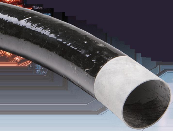

No burn-through eliminates elbow repairs
Lower material and installation costs
Fault resistance makes repairing cables easy
Durable and corrosion-resistant for project longevity

