

STOP INHERITING OTHER TRADES’ PROBLEMS
How AI-powered routing and coordination can eliminate weeks of coordination rework
Read more on pg. 38


As electrical firms ramp up their use ofartificial intelligence, some trends areemerging in why, where, how, and for whom.


ECMWEB.COM
With its exclusive online content, ecmweb.com is a valuable source of industry insight for electrical professionals. Here’s a sample of what you
NEC A look at the most bizarre “what’s wrong here” photos we ran this year
ecmweb.com/55335994
Editorial
Editor-in-Chief: Ellen Parson, eparson@endeavorb2b.com
Managing Editor: Ellie Coggins, ecoggins@endeavorb2b.com
Editor: Michael Morris, mmorris@endeavorb2b.com
Art Director: David Eckhart, deckhart@endeavorb2b.com
Consultants and Contributors
NEC Consultant: Mike Holt, mike@mikeholt.com
NEC Consultant: Russ LeBlanc, russ@russleblanc.net
BEST PRACTICES FOR SAFE OPERATION OF RECIPROCATING SAWS
Safety A reciprocating saw can be used safely and accurately if you understand some tricks and tips about using it. ecmweb.com/55340735 THE BEST OF THE WORST: 2025’S MOST INTERESTING WHAT’S WRONG HERE PHOTOS
Sales and Marketing
VP/Market Leader - Buildings & Construction: Mike Hellmann, mhellmann@endeavorb2b.com
Regional/Territory Account Manager: David Sevin, dsevin@endeavorb2b.com
Regional/Territory Account Manager: Jay Thompson, jthompson@endeavorb2b.com
Regional/Territory Key Account Manager: Ellyn Fishman, efishman@endeavorb2b.com
Account Manager: Steve Suarez, ssuarez@endeavorb2b.com

Production and Circulation
Production Manager: Josh Troutman, jtroutman@endeavorb2b.com
Ad Services Manager: Deanna O’Byrne, dobyrne@endeavorb2b.com
User Marketing Manager: James Marinaccio, jmarinaccio@endeavorb2b.com
Endeavor Business Media, LLC
CEO: Chris Ferrell
COO: Patrick Rains
CDO: Jacquie Niemiec
CMO: Amanda Landsaw CALO: Tracy Kane EVP Building & Construction Group: Chris Perrino VP of Content Strategy: Mike Eby
Electrical Construction & Maintenance (USPS Permit 499-790, ISSN 1082-295X print, ISSN 2771-6384 online) is published monthly by Endeavor Business Media, LLC. 201 N. Main St 5th Floor, Fort Atkinson, WI 53538. Periodicals postage paid at Fort Atkinson, WI, and additional mailing offices. POSTMASTER: Send address changes to Electrical Construction & Maintenance, PO Box 3257, Northbrook, IL 60065-3257. SUBSCRIPTIONS: Publisher reserves the right to reject non-qualified subscriptions. Subscription prices: U.S. ($68.75 year); Canada/Mexico ($ 112.50); All other countries ($162.50). All subscriptions are payable in U.S. funds. Send subscription inquiries to Electrical Construction & Maintenance, PO Box 3257, Northbrook, IL 60065-3257. Customer service can be reached toll-free at 877-382-9187 or at electricalconstmaint@omeda.com for magazine subscription assistance or questions.

on our site right now: ELECTRICAL SAFETY REFRESHER
E-Book From the EC&M e-books library: Best practices for fostering an electrically safe working environment ecmweb.com/55337125
Printed in the USA. Copyright 2026 Endeavor Business Media, LLC. All rights reserved. No part of this publication may be reproduced or transmitted in any form or by any means, electronic or mechanical, including photocopies, recordings, or any information storage or retrieval system without permission from the publisher. Endeavor Business Media, LLC does not assume and hereby disclaims any liability to any person or company for any loss or damage caused by errors or omissions in the material herein, regardless of whether such errors result from negligence, accident, or any other cause whatsoever. The views and opinions in the articles herein are not to be taken as official expressions of the publishers, unless so stated. The publishers do not warrant either expressly or by implication, the factual accuracy of the articles herein, nor do they so warrant any views or opinions by the authors of said articles.
Reprints: Contact reprints@endeavorb2b.com to purchase custom reprints or e-prints of articles appearing in this publication.
Photocopies: Authorization to photocopy articles for internal corporate, personal, or instructional use may be obtained from the Copyright Clearance Center (CCC) at (978) 750-8400. Obtain further information at www.copyright.com.
Archives and Microform: This magazine is available for research and retrieval of selected archived articles from leading electronic databases and online search services, including Factiva, LexisNexis, and ProQuest.
Privacy Policy: Your privacy is a priority to us. For a detailed policy statement about privacy and information dissemination practices related to Endeavor Business Media products, please visit our website at www.endeavorbusinessmedia.com.
Please Note: The designations “National Electrical Code,” “NE Code,”


How AI Is Reshaping the Electrical Industry’s Path Forward
By Ellen Parson, Editor-in-Chief

Last month, we presented our annual construction forecast to evaluate business conditions and help our audience prepare for the upcoming year. Written by Jim Lucy, head of content for Electrical Wholesaling and Electrical Marketing, this piece covered significant factors that will affect the market but emphasized one key trend in particular: market bifurcation — characterized by high growth in areas such as data centers in contrast with declining activity in others (like residential, office, and industrial sectors), ultimately revealing the “K-shaped” economy concept everyone’s been hearing about lately. Other significant considerations in 2026’s economic outlook included the potential impact of tariffs, immigration enforcement, and supply chain issues not to mention material price increases and ongoing skilled labor shortages. Following up on the K-shaped economy conversation, we have an excellent article in this month’s issue, starting on page 47 and written by Alex Chausovsky, director of analytics and consulting at the Bundy Group, that outlines what this could mean for our readers as we enter 2026. He suggests: “Planning for mild, single-digit macroeconomic growth next year appears to be the prudent thing to do. However, an acknowledgement of the fact that we’re traversing a K-shaped economy — with winning and losing sectors — is equally prudent.” Ultimately, in order to be competitive, electrical design and electrical contracting firms should adopt a nimble approach to capitalize on high-growth sectors (upper arm of the “K”) and mitigate risks from the underperforming areas (lower arm). Since AI is fueling the data center construction boom, it becomes a driving force behind the K-shaped economy, concentrating growth for companies working in the electrical space that can align their strategy with AI-driven infrastructure demand going into the new year. That’s one reason we made “AI and automation in electrical applications” a key theme in this January issue. To see how electrical firms are ramping up their use of artificial intelligence, turn to page 42 for a lesson on “The Electrical Industry’s AI Learning Curve,” written by Freelancer Tim Kridel. For electrical professionals who may worry about AI taking their jobs someday, I absolutely loved the analogy given by Ryan Elbert, executive vice president and global director of engineering and development services at Black & Veatch. He believes: “One day soon, you’ll catch yourself telling interns and apprentices, ‘Before we had AI ...,’” In the article, Elbert reminisces about the days when he didn’t even have a computer on his desk — let alone one connected to the internet/cloud. All these years later, he’s happy to report he wasn’t replaced by a computer; therefore, it’s unlikely you’ll be replaced by AI anytime soon. As powerful as AI is, the article reminds us that it is still just a tool — one that’s far better at answering questions than knowing what to ask. Another expert source interviewed for that article, Dustin Schafer, CTO of Henderson Engineers, reminds us: “You don’t lose your job to AI. You lose your job to a person who’s using AI — and everyone wants to be the person using AI.”
In the cover story, starting on page 38, Aaron Szymanski, co-founder and head of product at Augmenta, delivers a phenomenal piece on how electrical contractors can “Stop Inheriting Other Trades’ Problems” by outlining the ways in which AI-powered routing and coordination can eliminate weeks of coordination rework. By using this novel approach, electrical contractors can move away from siloed workflows to foster a more collaborative environment and minimize costly rework and scheduling delays. “The solution is a fundamental shift in philosophy that moves construction design closer to the automated, rule-based efficiency found in advanced manufacturing” he writes. “This can be achieved through the introduction of spatial AI in the design process.” Read the full article for tips on how adopting advanced technology can position you as a strategic partner in the building process, which translates into securing more complex, high-margin projects with greater confidence in the long run.


ELECTRICAL TESTING EDUCATION Understanding NFPA 70E and the Condition of Maintenance
Are you familiar with Informative Annex S and its role in assessing/maintaining electrical equipment?
By Ron Widup, Shermco Industries
Condition of maintenance” is a phrase often used in NFPA codes and standards, but do you really understand what it means? If not, take a look at Informative Annex S, “Assessing the Condition of Maintenance,” in the 2024 edition of NFPA 70E, Standard for Electrical Safety in the Workplace.
NFPA 70E REQUIREMENTS
Where is the condition of maintenance referred to in NFPA 70E? Let’s look at a few relevant Sections.
The general requirements in Sec. 110.3 state that the condition of maintenance must be addressed.
Sec. 110.3(C) Condition of Maintenance. The electrical safety program shall include elements that consider the condition of maintenance of electrical equipment and systems.
Annex S, Sec. S.3, Electrical Safety Program, clearly states that you must consider the condition of maintenance in your electrical safety program:
… the employer shall implement and document an overall electrical safety program that directs activity appropriate to the risk associated with electrical hazards.
This is further clarified in Sec. 110.5, Host and Contract Employers’ Responsibilities, which also states:
Sec. 110.5(C) Condition of Maintenance. An electrical safety program must consider the condition of maintenance of the equipment and its component parts.
Now you have a clear requirement in general terms. You also have a specific requirement, if you are a host
employer or a contract employer, to consider the condition of maintenance in your electrical safety program, as per Art. 205:
… safe normal operation of equipment is dependent on the condition of maintenance.
WHAT IS A CONDITION OF MAINTENANCE?
Let’s start with the definition of “condition of maintenance,” which is the same in NFPA 70B, Standard for Electrical Equipment Maintenance, and NFPA 70E: The state of the electrical equipment considering the manufacturers’ instructions, manufacturers’ recommendations, and the applicable industry codes, standards, and recommended practices.
Now, let’s dissect the three main parts of the definition to understand its meaning further.
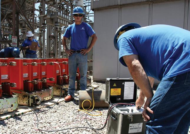
PART 1: THE STATE OF THE ELECTRICAL EQUIPMENT
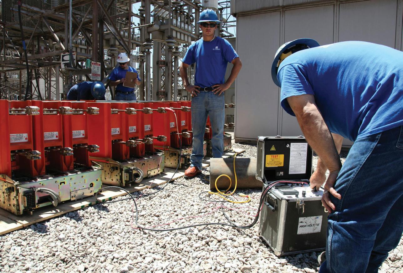
It seems obvious, but don’t overlook the state of electrical equipment. It’s the overall condition of the equipment (Photo 1) as you see it and begin to interact with it. Is it new? Service aged? Clean? Dirty? Good condition? Poor condition? All those factors need to be considered.
PART 2: CONSIDERING THE MANUFACTURERS’ INSTRUCTIONS AND RECOMMENDATIONS
You now need to apply further reasoning and analysis to the overall condition of
Photo 1. These workers are testing a medium-voltage circuit breaker. How equipment has been cared for is part of the condition of maintenance analysis.
the electrical equipment. You will want to consider:
• How well has it been cared for?
• What environment does it live in?
• Is the environment suitable?
• Is the equipment rated for your application?
• How did the original manufacturer expect you to use it?
• Has it been installed in an area as intended and designed?
These considerations can affect things greatly if not answered correctly.
PART 3: CONSIDERING APPLICABLE INDUSTRY CODES, STANDARDS, AND RECOMMENDED PRACTICES.
Finally, have the previous two components been considered in conjunction with best practices and industry consensus? Are you looking after it properly and maintaining it in accordance with what those in the industry say you should? This is another important aspect of the

Electrical Testing Education articles are provided by the InterNational Electrical Testing Association (NETA), www.NETAworld.org. NETA was formed in 1972 to establish uniform testing procedures for electrical equipment and systems. Today the association accredits electrical testing companies; certifies electrical testing technicians; publishes the ANSI/NETA Standards for Acceptance Testing, Maintenance Testing, Commissioning, and the Certification of Electrical Test Technicians; and provides training through its annual conferences (PowerTest and EPIC — Electrical Power Innovations Conference) and its expansive library of educational resources.

definition and an important piece of the overall definition.
ADDITIONAL ELEMENTS TO CONSIDER FOR PROPER OPERATING CONDITION
Remember: Operating condition and condition of maintenance are two different things. Maintenance is just one part of normal operation. Other elements of operating condition include these seven items:
• The equipment is properly installed.
• The equipment is properly maintained.
• The equipment is rated for the available fault current.
• The equipment is used in accordance with the instructions included in the listing and labeling and with the manufacturer’s instructions.
• The equipment doors are closed and secured.
• All equipment covers are in place and secured.
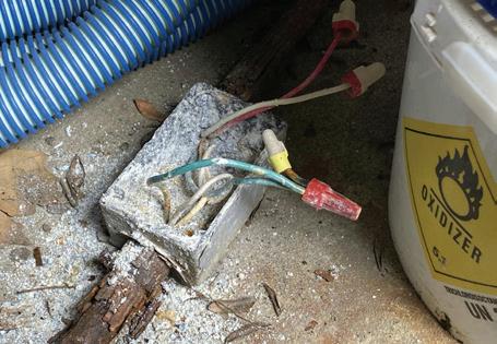
• There is no evidence of impending failure (Photo 2).
DIVING INTO INFORMATIVE ANNEX S
Now that we understand what shape the equipment is in, it’s clear that Art. 205 states safe operation is dependent on it. But where can you seek guidance in NFPA 70E for the condition
of maintenance? Look to Informative Annex S, Assessing the Condition of Maintenance.
It provides guidance for understanding the condition of maintenance. Here’s an abbreviated summary of the information. For a complete review, study NFPA 70E, Informative Annex S in full.
S.1 Introduction. The objective of these requirements is to emphasize the inherent risk to workers associated with performing tasks on electrical equipment that is not properly rated, installed, and maintained, or otherwise exhibits evidence of an increased risk level for electrical workers or operators.
S.2 Assess the risk. Safe work practices should always be used when gathering information to be used to assess the condition of maintenance of electrical equipment.
S.3 Visual inspection. Visual inspection of equipment (Photo 3 on page 12) can be used to verify that it is installed professionally and skillfully in accordance with applicable industry codes and standards and the manufacturer’s instructions.
S.4 — Periodic testing and inspection. Periodic testing and detailed inspection methods are used to help workers determine the condition of the equipment at the time of the test.
S.5 — Permanently installed monitoring. Continuous monitoring of specific equipment conditions can
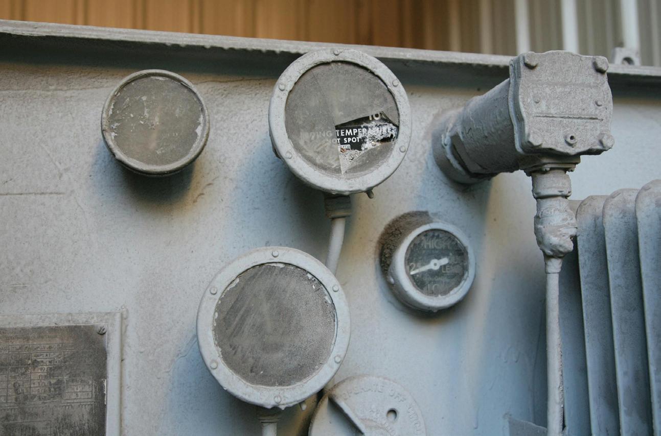
Photo 2. Environment and evidence of impending failure must be considered before interacting with equipment.
ELECTRICAL TESTING EDUCATION

PQ Newsbeat
If you’re an engineer, commercial or industrial facility manager, or electric utility employee concerned about the quality and reliability of power delivery, this e-newsletter (sent out monthly) is for you.
Topics covered include:
• Power quality
• Voltage sags & swells
• Transients
• Harmonics
• Power factor
• Test & measurement techniques
Subscribe Today
See all of our EC&M e-newsletters at www.ecmweb.com
be performed using an uninterrupted method of data collection. The use of real-time data is useful when determining the condition of the equipment and is also used to modify (shorten or lengthen) the predetermined maintenance intervals for other inspections and tests.
S.6 — Predictive techniques. These technologies and methods often detect minor items before they propagate into major issues or equipment failure, enabling workers to interact with or operate the equipment while it is still in a normal operating condition as opposed to an abnormal condition.
S.7 — Maintenance history. The maintenance history of electrical equipment is an important factor to consider when assessing if the equipment has been properly maintained in accordance with the manufacturer’s recommendations and applicable industry codes and standards.
• S.7.1 — Labels. Labels, decals, or other markings might be color-coded and placed on the exterior enclosure or surface of the electrical equipment or device to communicate the condition of maintenance as of the last assessment (see Figure above).
• S.7.2 — Digital and other electronic methods. Digital technology is used as a method of storing and sharing maintenance-related information.
S.8 — Standard for electrical equipment maintenance. NFPA 70B provides a means to establish and maintain an acceptable condition of maintenance of electrical equipment and systems to address safety and reliability.
CONCLUSION
If you apply the guidance provided in the ANSI/NETA testing standards to your electrical equipment, you can be assured that the proper visual, mechanical, and electrical tests have been performed on the equipment, which ultimately leads to a safer and more reliable power system.
In summary: Read the standards, and understand the content. You’ll be glad you did.
Ron Widup is the vice chairman, board of directors, and senior advisor of technical services for Shermco Industries and has been with Shermco since 1983. He can be reached at rwidup@shermco.com
Visual inspection is an important aspect of overall risk assessment. What do you think when you look at these transformer gauges?
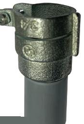
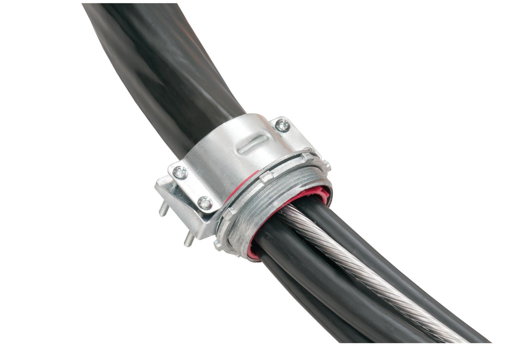
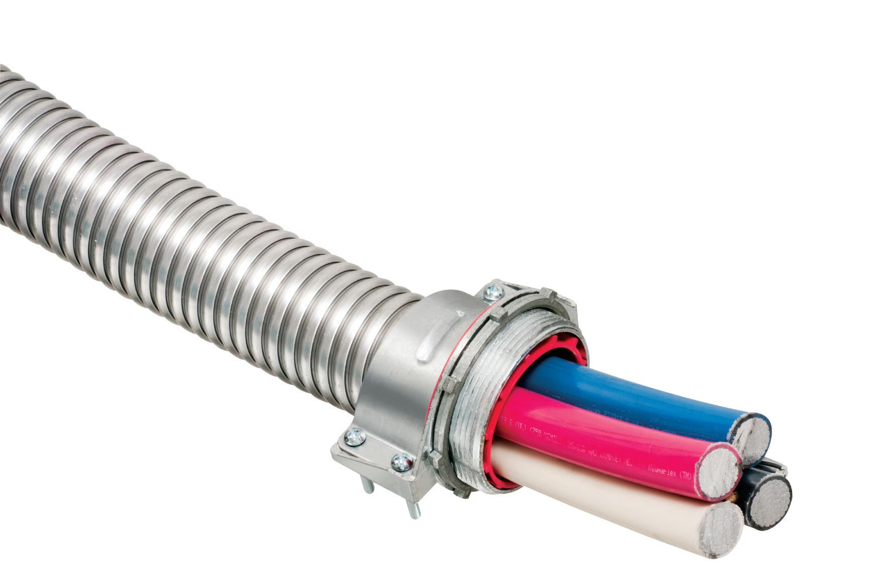
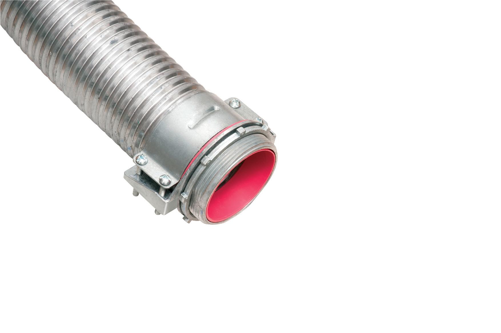
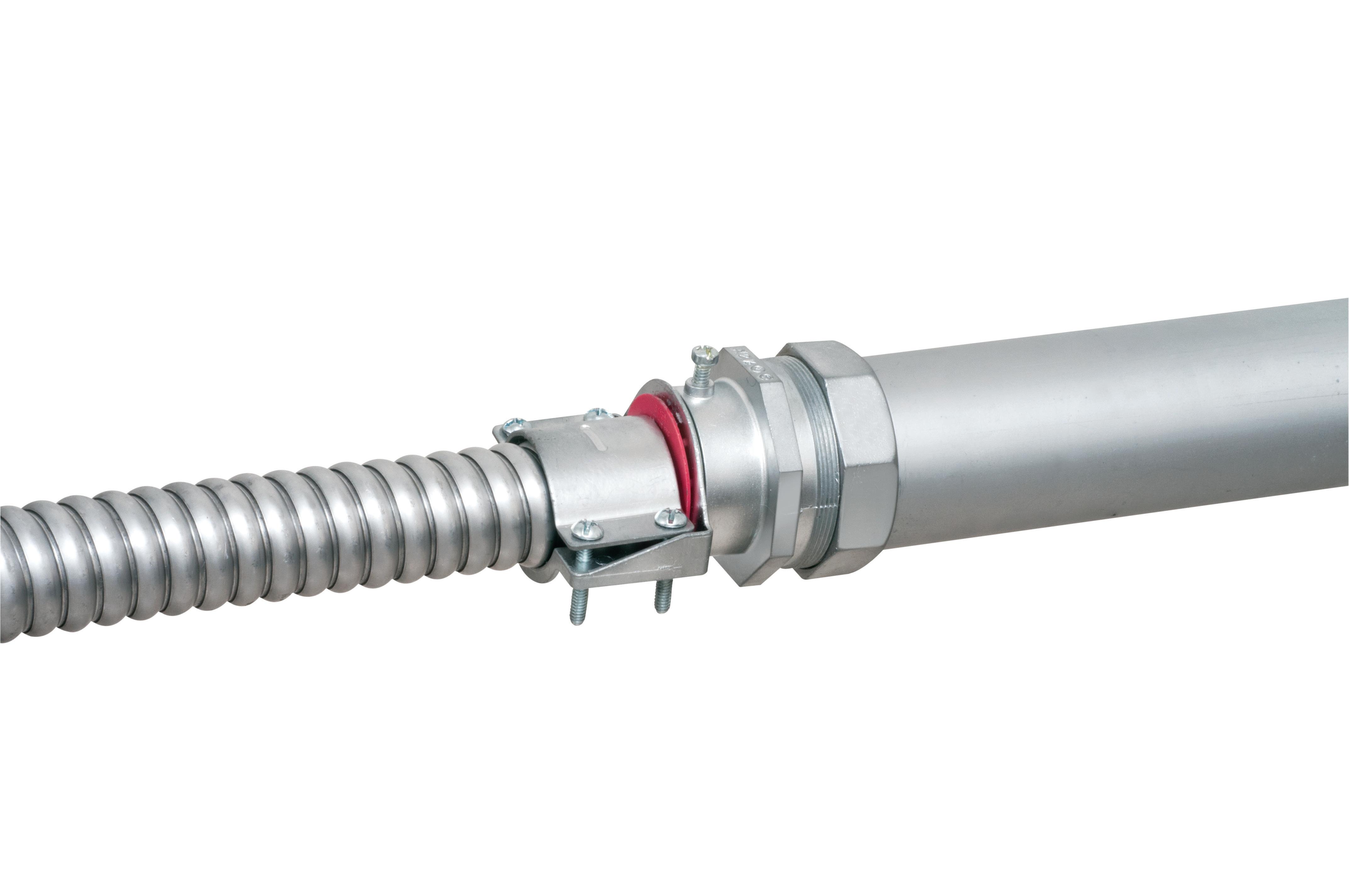
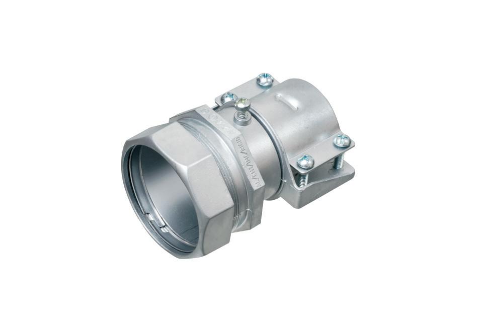
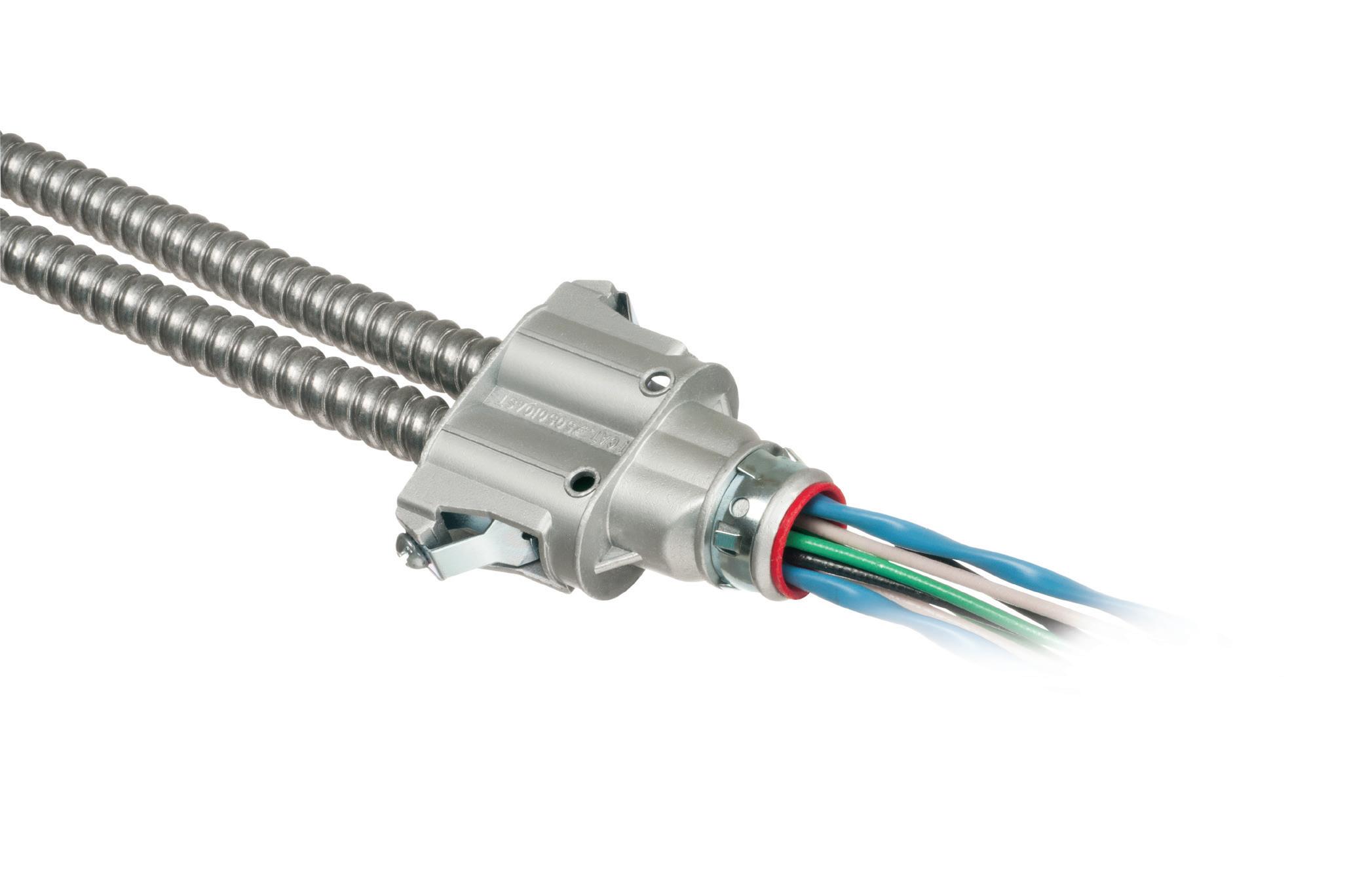
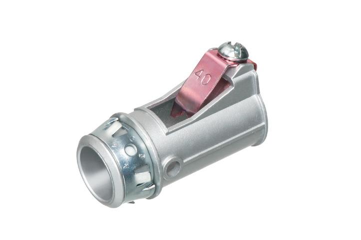
MC CABLE FITTINGS
ONE FITTING FITS MULTIPLE CABLE/CONDUIT TYPES & SIZES


* Aluminum & Steel Flexible Metal Conduits

ONE trade size fits SEVERAL cable types and sizes, plus flexible metal conduit for super convenience and cost-savings! Reduces inventory and material handling too.

Patented
Conductor Size CSA TECK90 Conductor Size # of Conductors* # of Conductors* (AWG/KCMIL) (AWG/KCMIL/ACWU) 6/3, 6/4, 4-3, 4-4, 8/3, 8/4, 6/3
2-3, 2-4, 1-3
2-3, 2-4, 1-3, 1-4, 6/3, 6/4, 4/3, 4/4, 3/3, 1/0-3, 1/0-4, 2/0-3, 3/4, 2/3, 2/4
2/0-4, 3/0-3
2/0-4, 3/0-3, 3/0-4, 2/4, 1/3, 1/4, 1/0-3 4/0-3, 4/0-4, 250-3, 250-4 1/0-4, 2/0-3 250-4, 300-4, 350-3, 2/0-3, 2/0-4, 3/0-3, 3/0-4, 350-4, 500-3 4/0-3, 4/0-4, 250-3 500-3, 500-4, 600-3 4/0-4, 250-3, 250-4, 300-3 600-4, 750-3 300-4, 350-3, 350-4, 500-3 600-4, 750-3, 750-4 350-4, 500-3, 500-4 750-3, 750-4, 1000-4 750-3, 750-4, 1000-3
Concrete tight when taped
10 Hot Local Markets to Watch in 2026
See which markets will be strong in 2026 — and which surprise areas are ripe for electrical construction work.
By Jim Lucy, Editor-in-Chief, Electrical Wholesaling

Electrical Marketing ’s ( EM ’s) annual picks for hot markets to watch over the next 12 months are in, and there are a few surprises as well as some perennial all-stars.
Most of our picks this year have made our list of hot markets in the past because of impressive increases in both estimated sales potential and population growth. We also watch residential closely at the local level, but in many markets, both single-family and multifamily building permits aren’t currently increasing at impressive levels.
LOUDOUN COUNTY
New to our picks (see Table on page 18) is Loudoun County, Va., which enjoyed some huge growth in electrical contractor potential, thanks in large part to being home to the largest concentration of data centers in the United States. In addition to the $1.92-billion Realty LLC data center campus that entered the planning stages in April 2025, there’s also a $500-million
retrofit of Dulles Airport’s Concourse E on the drawing boards. Loudoun County’s estimated electrical contractor sales potential increased by $178 million YOY, according to EM’s estimates.
CINCINNATI, COLUMBUS, AND INDIANAPOLIS METROS
We are also highlighting three metropolitan statistical areas (MSAs) in the Midwest — Cincinnati, Ohio-Ky.-Ind.; Columbus, Ohio; and Indianapolis-Carmel-Anderson, Ind.
The Cincinnati metro has a big hospital project in the pipeline: the $365-million Cincinnati Children’s Hospital in Liberty, Ohio. Columbus contractors are working on the $1.8-billion John Glenn Columbus Airport project that broke ground in February 2025 and are hoping plans for billions in new construction become a reality, including Intel Corp.’s plan (recently delayed) for the $20-billion Johnstown Gateway Planned District near several

semiconductor plants; a $500-million Amazon data center in Jefferson, Ohio; and Google’s $28-billion expansion project in New Albany, Ohio.
The Indianapolis metro is seeing a nice mix of commercial, institutional, and industrial construction. The largest construction project underway that EM’s editors found is the $2.25-billion Eli Lilly Medicine Foundry in Lebanon, Ind., an Indianapolis suburb. Also of note are the $571-million Signia Hotel project underway in Indianapolis, the $200-million Westin Hotel being built at Indianapolis Airport, and the $187-million Purdue University Academic Success Building being built in West Lafayette, Ind.
BOISE, IDAHO
Boise, Idaho caught the eye of EM’s editors because of its growth over the past year in estimated total sales potential, electrical contractor sales, and industrial sales potential. EM estimates that its 2025 total electrical sales potential

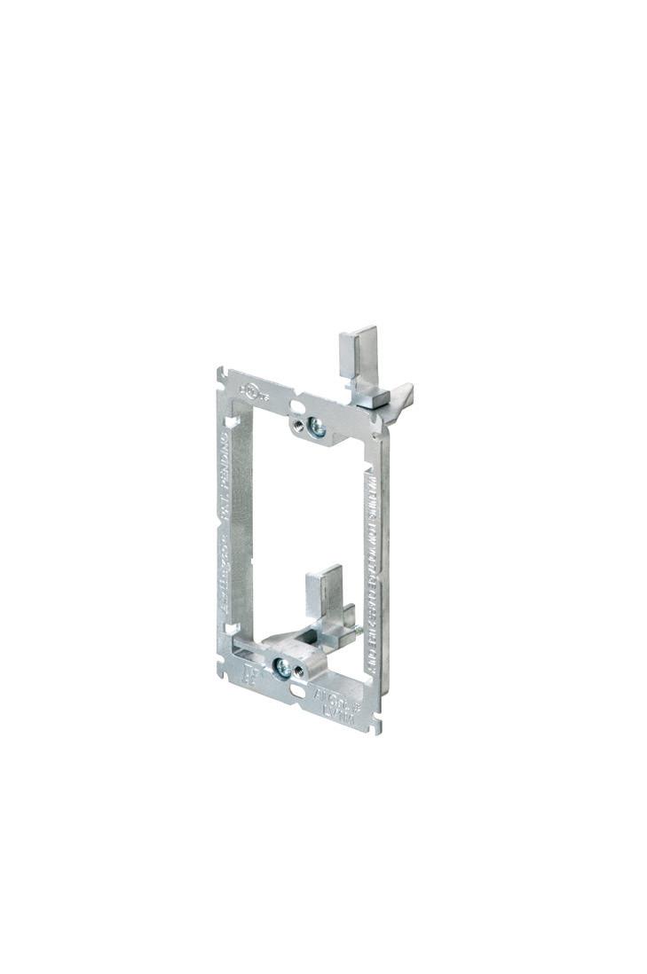

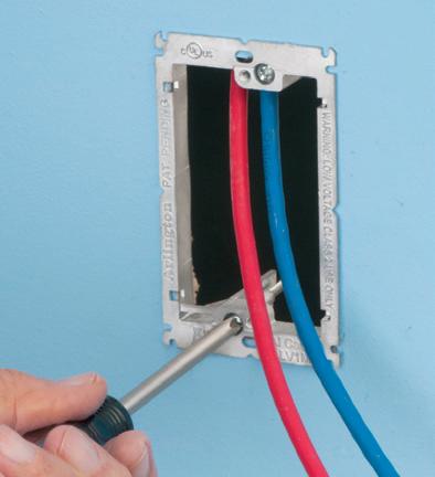
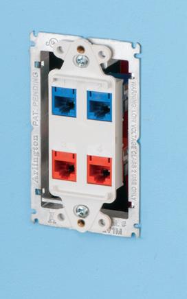


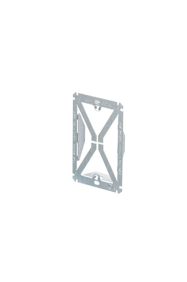
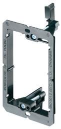
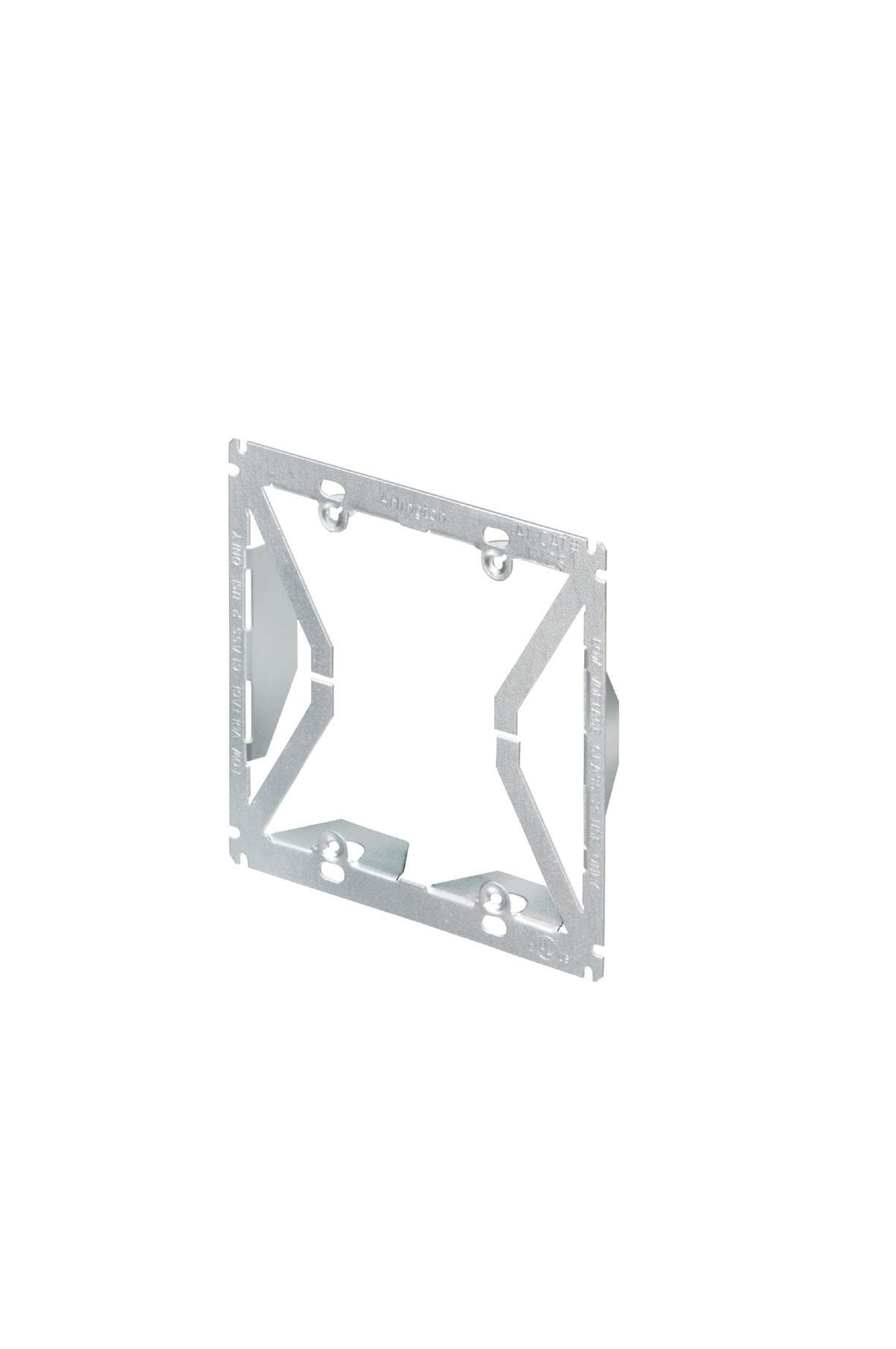
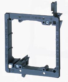
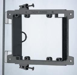
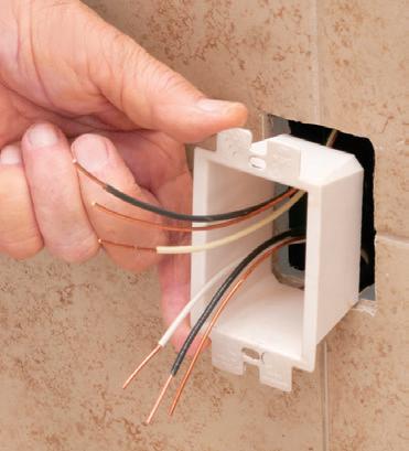
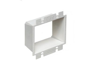
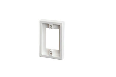
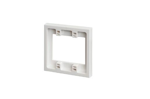
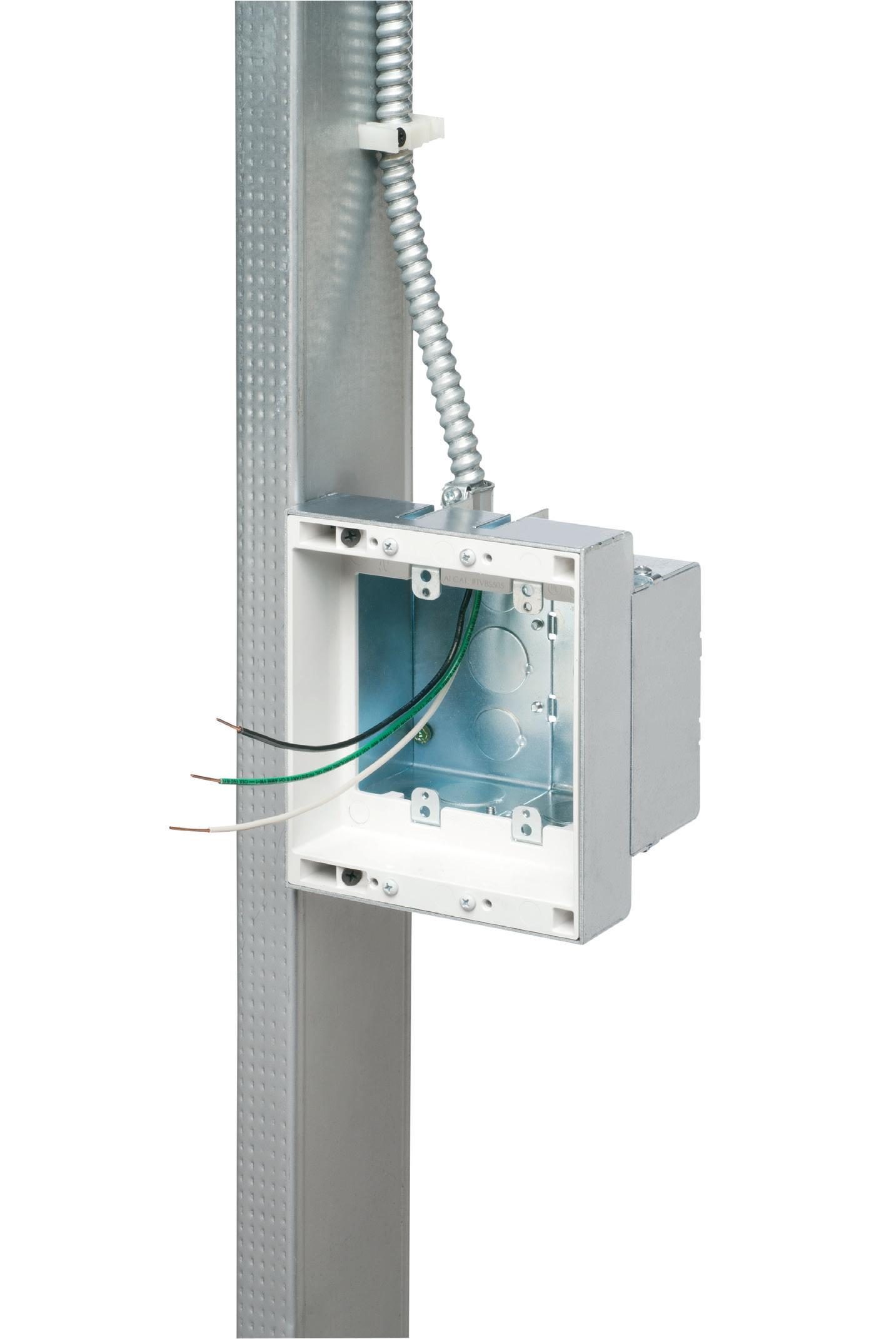
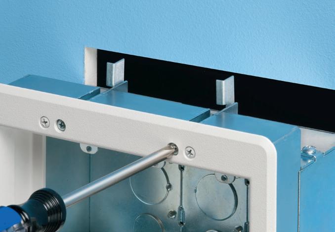
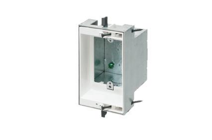
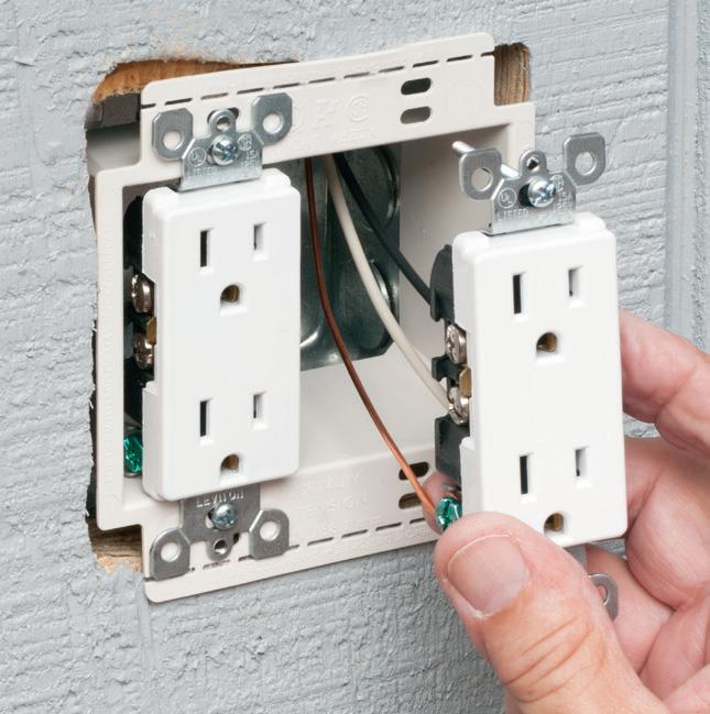
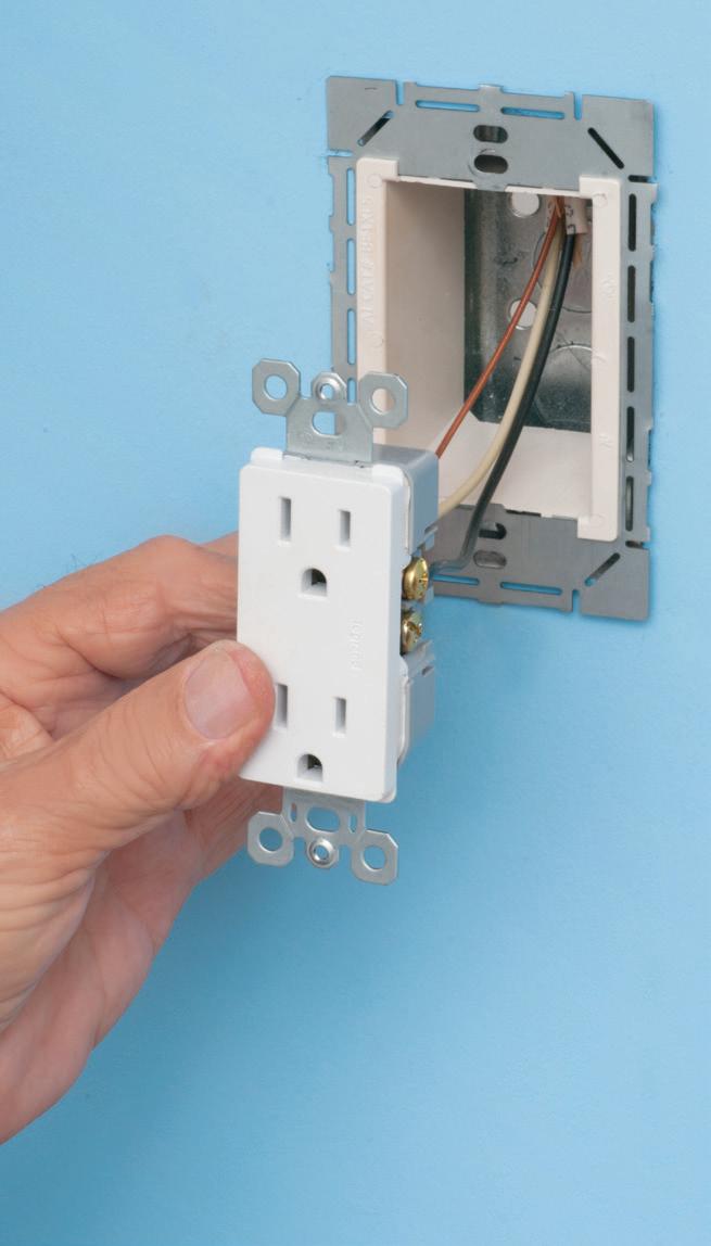
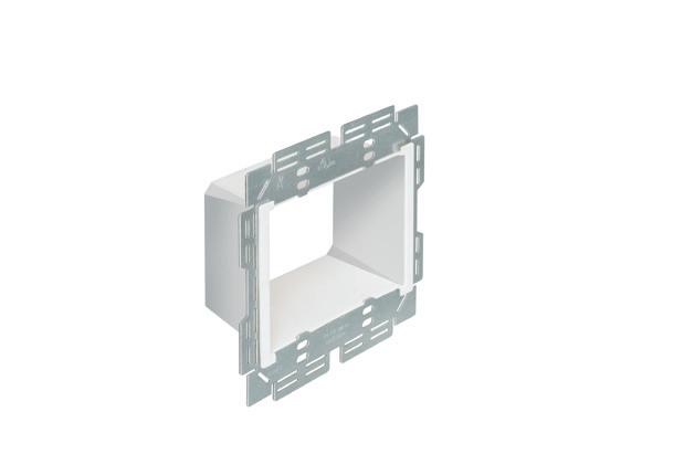
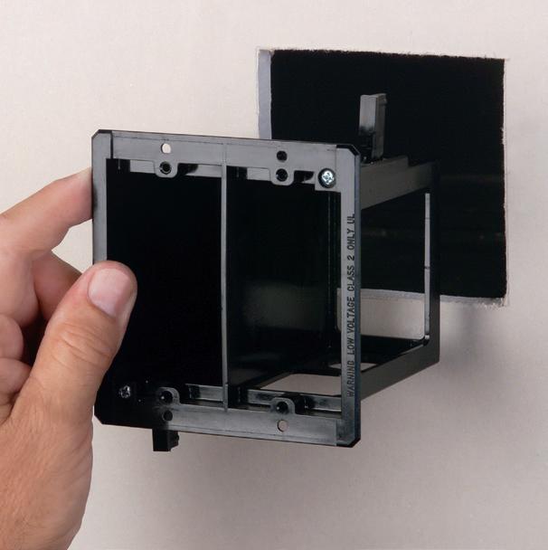
Arlington’s Low Voltage Mounting Brackets are the solution for fast and easy cut-in installation and mounting of Class 2 communications, computer and cable TV wiring and connections.
Introducing METAL low voltage mounting brackets for EXISTING or RETROFIT construction...
LV1M and LV2M COMMERCIAL GRADE
• Extra rigidity and stability where performance and visibility are important or critical
• Threaded holes for easy, fast device installation
• Adjustable bracket for 1/4" to 1" wall board thicknesses
Our LV1S and LV2S PLATED STEEL bracket design, provide excellent stability and secure installation of low voltage devices in 1/4" to 1-1/4" walls - without an electrical box.


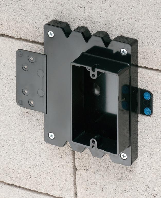
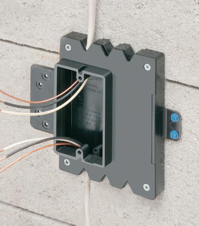
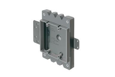
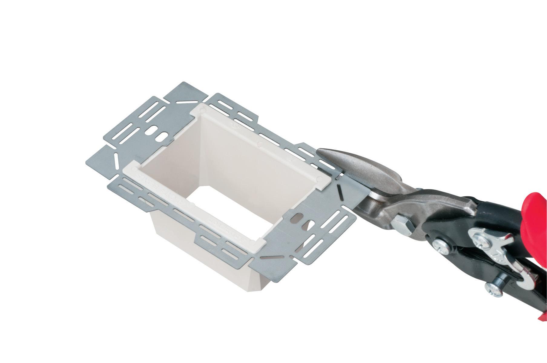
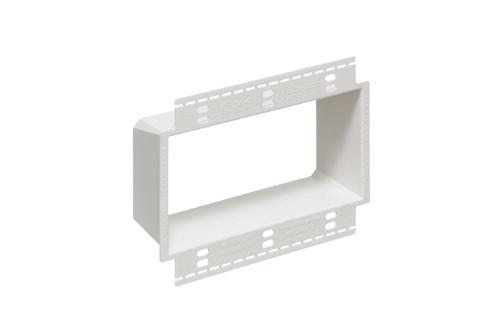
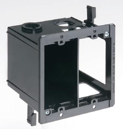
Large Volume FURRED WALL BOX
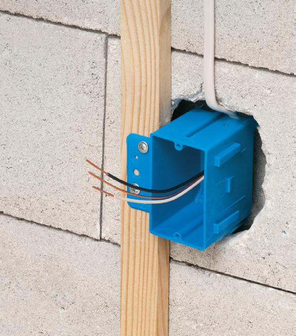


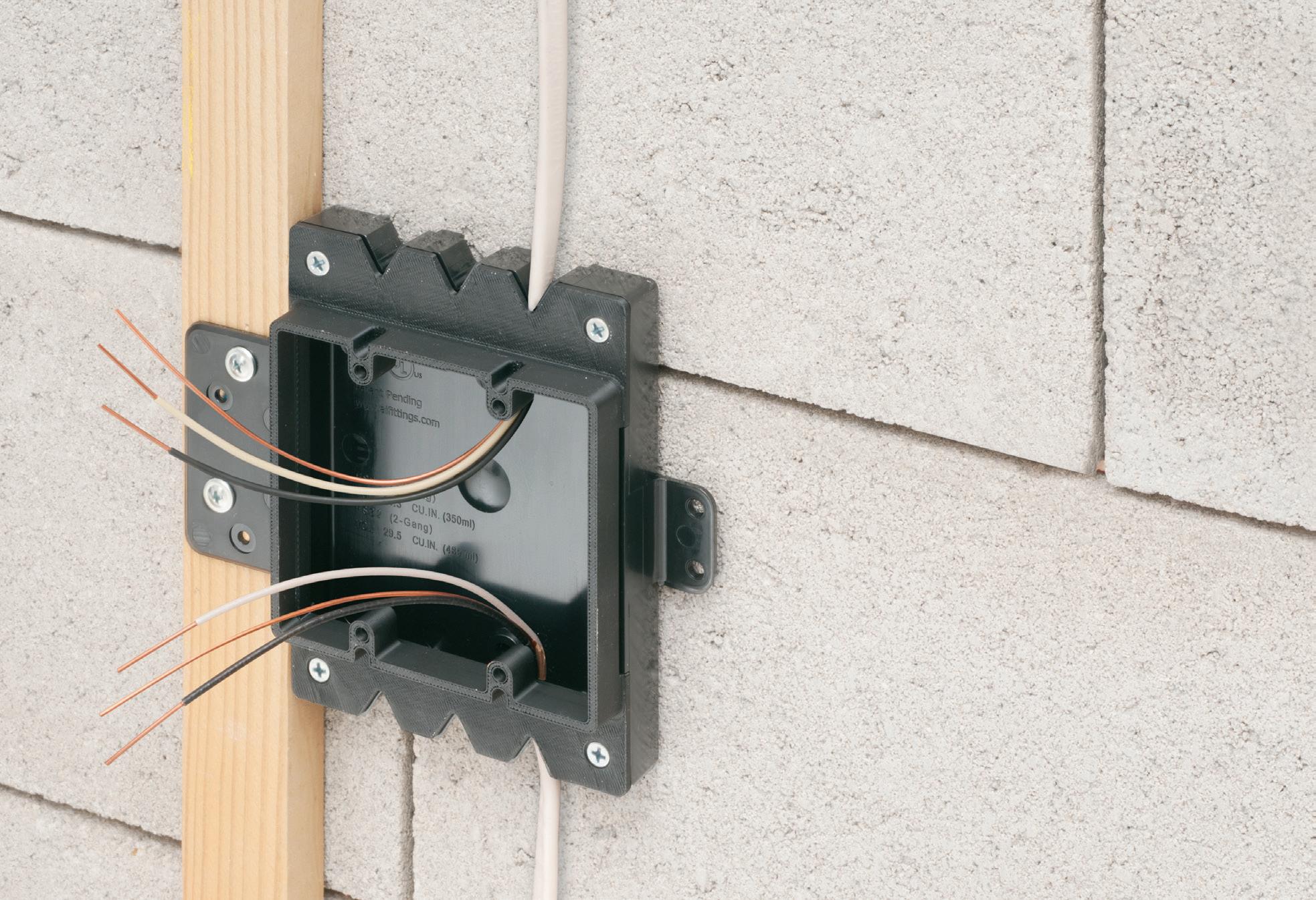
Arlington’s new Furred Wall Box® kit makes challenging outlet box installations fast and easy!
Versatile mounting options Our high strength FSB series outlet box kits are designed for use with existing 1x2 drywall furring strips – but can also be mounted directly to a concrete block wall between furring strips. Place the box or outlet where it’s needed.
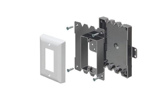
Integral cable securement – No pullout! Accommodates GFCI and USB receptacles. Convenient kits simplify ordering of FSB1 and FSB2.
High-strength No breakage in cold weather
Integral Mounting Flanges
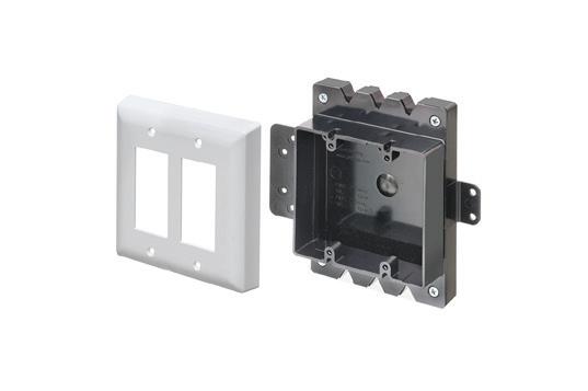
FSB2
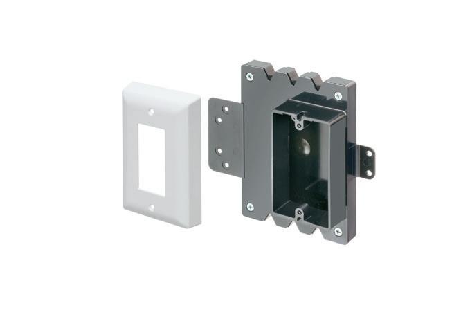
FSB1 Single gang on Block Wall
Low Profile
NEW FSB12 * FSB22
ADD OUR BOX EXTENDERS to BROADEN APPLICATION and USE
Furring strip flange Mounting Bracket
Base
Assemblies for 1/2" Wall Thickness & Standard Depth
Install on 1x2 Furring Strips or Block Wall with 1/2" Drywall
One-gang FSB12
Block wall flange Mounting
Our NEW Low Profile single and two-gang Furred Wall Box® base assemblies have 1/2" raised ring for use with standard wall plates.
They combine with Arlington’s Box Extenders to deliver installation solutions for wall thicknesses from 1/2" to 1-1/2" and varying device depths
• Integral cable securement – No pullout!
• For standard and GFCI devicesUses standard wall plates
• Single gang FSB12 - 17.0 cu. in. Two-gang FSB22 - 20.5 cu. in.

Add our BOX EXTENDERS for these specific conditions...
1 if Total Wall Layer Thickness is GREATER than 1/2" (up to 1-1/2") Add BE1 or BE2

if Using a Deep Depth Device with 1/2" Wall Thickness Add BES1 or BES2

or Dimmer

Bracket
MARKET WATCH
10 LOCAL MARKETS TO WATCH IN 2025
Sources: Metropolitan Statistical Area (MSA) data from 2Q 2025 and 2Q 2024 from the U.S. Bureau of Labor Statistics (BLS); Loudoun County, VA, data from 1Q 2025 and 2Q 2024 from BLS. Building permit and population data downloaded from U.S. Census Bureau website.
While many of the hottest markets are in the Sunbelt, Cincinnati, Columbus, Ohio, and Indianapolis also made this year’s list of fast-growing construction metros.
grew $58.6 million to $612.7 million, a solid 10.6% increase supported in large part by a $43.4-million increase (12%) in contractor sales potential.
The largest construction project underway in the Boise area is a new 1.2 million-sq-ft Micron plant, which, according to www.wscarpenters.org, is
worth $15 billion in total construction value and will employ 2,000 workers at its expected 2026 opening date.
The area continues to attract new residents in a big way, with the population of the area growing by 75,605 between 2020 and 2024. That averages out to an estimated 41 new residents per day.
CHARLOTTE-CONCORDGASTONIA, N.C.-S.C. AND RALEIGH, N.C.
For years, North Carolina has been a top growth market, and these two MSAs are often powering a big chunk of the construction activity and population growth. The state was also recently


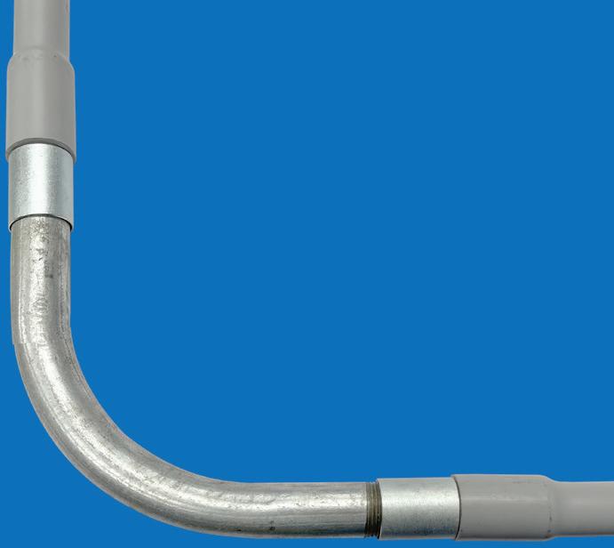
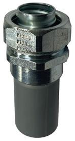
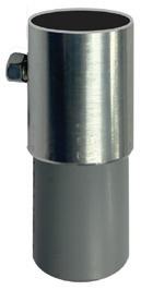
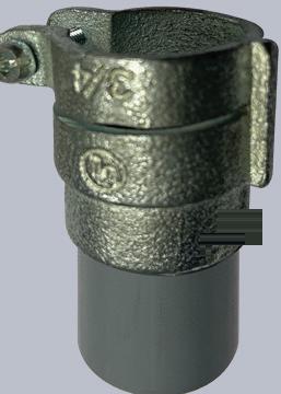
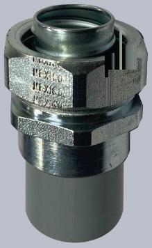
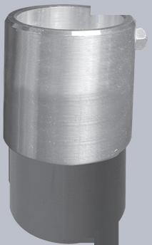
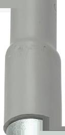
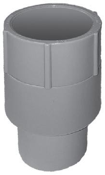
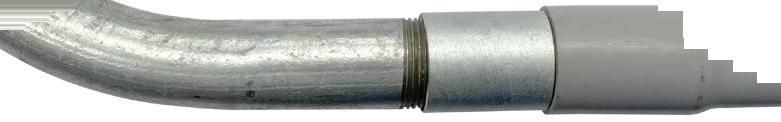
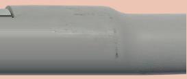
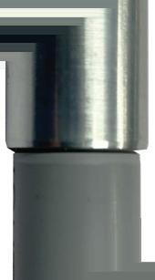
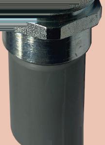
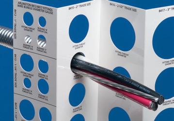
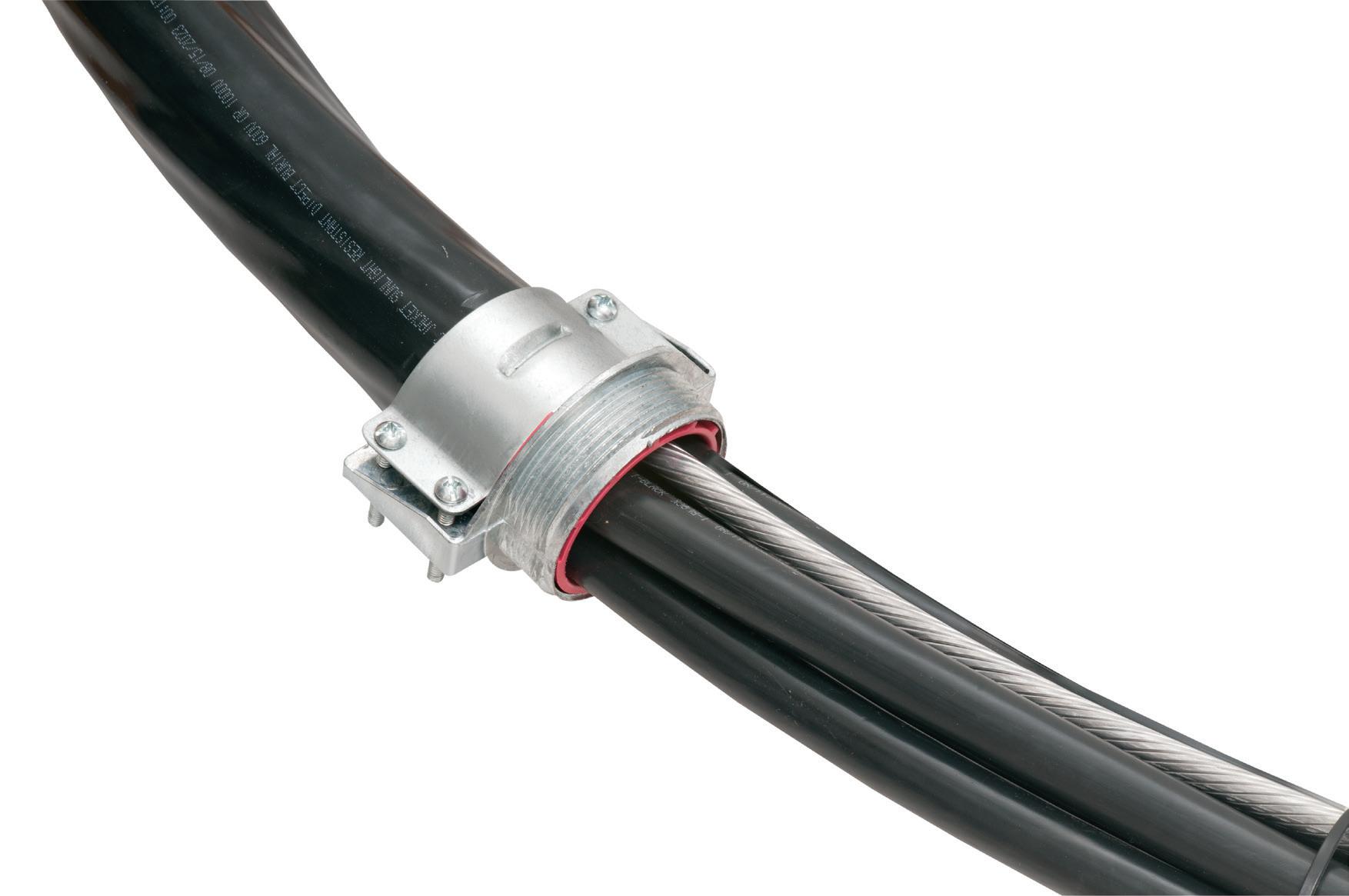
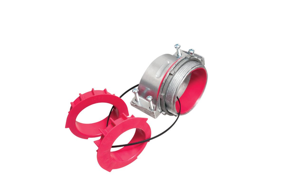
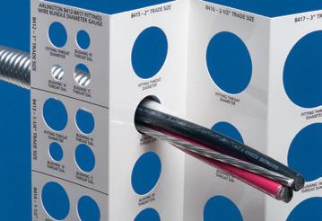
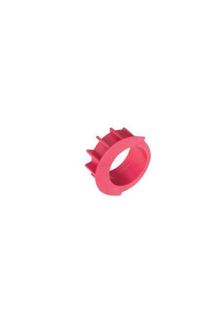
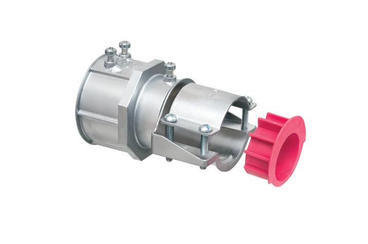
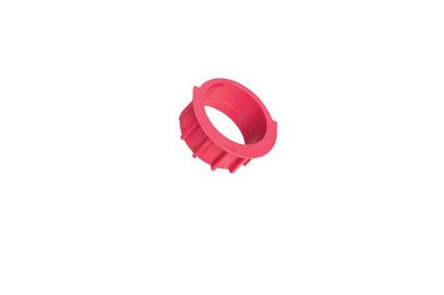
Perfect for data center remote power panel feeds, panels, equipment feeds and EV Chargers in parking garages, Arlington’s Listed CableStop® Transition Fittings deliver the efficient, cost-effective way to transition feeder cables to 1.25", 2.5", 3" and 3.5" EMT, IMC and RMC conduit in protective drops, risers and feeds to panels and equipment. Our new CableStop fittings integrate our patented, versatile and SKU-reducing 8412 series cable fittings, with Arlington conduit fittings, allowing for easy transitions to larger knockout sizes.
Available with set-screw or compression connections into 1.25", 2.5", 3" and 3.5" conduit, they ship with multiple end stop bushings that vary the size of the opening – along with a free template select the right bushing for the cable.


MARKET WATCH

ElectricalZone
This weekly e-newsletter offers subscribers a unique and inside view into the most important trends, technologies, and developments taking place within the electrical industry.
Topics covered include:
• EC&M videos & podcasts
• Market forecasts and analysis
• Code Quiz of the Week
• Online-only feature articles
• Late-breaking industry news
Subscribe Today
See all of our EC&M e-newsletters at www.ecmweb.com

recognized as 2025’s No. 1 State for Business by CNBC.
Although both metros are seeing increases in contractor sales potential at just over the national level percentage of roughly 2%, big construction projects in the pipeline, a double-digit YOY increase in Raleigh’s multi-family building permits, and the always impressive population growth in both cities made these metros Top 10 picks. The Charlotte metro has several big data center projects in the proposal stage, including a $10-billion Amazon data center and AI campus in Hamlet, N.C. A large industrial project of note is the $380-million PPG factory under consideration in Shelby, N.C. Charlotte has also seen massive population growth over the past four years, according to U.S. Census Bureau data. The metro’s population increased by 215,006 residents from 2020 to 2024.
Raleigh is also seeing big-time population growth, with an increase of 144,861 from 2020-2024 for an estimated 86 new residents each day. Through July 2025, the metro was one of the few MSAs in the nation seeing a double-digit increase in multi-family building permits, with a 13.8% year-to-date increase to 3,682 permits. No doubt some of these new residents will eventually be moving into two new multi-family projects now under construction — the $200-million Strand mixed-use project with 362 units and the $200-million Highline
Glenwood residential tower that will top out at 37 stories. The city also announced plans for a $387-million expansion of its convention center in October.
MIAMI, ORLANDO, AND TAMPA-ST. PETERSBURG
It was tough to not include perennial high-growth Florida metros like Jacksonville, Sarasota, and Fort Myers-Cape Coral in this year’s picks, but Miami, Orlando, and Tampa-St. Petersburg just had too many construction projects underway and in the pipeline to ignore. Miami had five multi-family projects topping $200 million in total contract value, the $350-million Riverside Wharf mixed-use project, as well as a $600-million airport project and eye-popping numbers of new residents moving into the area — 324,486 from 2020-2024 and an estimated 307 new folks coming into town every day. The Orlando area has plenty of stadium, airport, and theme park construction in the pipeline to keep contractors busy for a long time, as well as stellar population growth numbers. And the Tampa-St. Petersburg metro has a $1.5-billion airport project underway, a ton of downtown construction, and an estimated 148 new residents moving in each day.
Additional data on these markets, as well as 300 other MSAs, can be downloaded at www.electricalmarketing.com.
Multi-family construction projects and vast numbers of new residents moving to the area continue to change Miami’s downtown skyline.


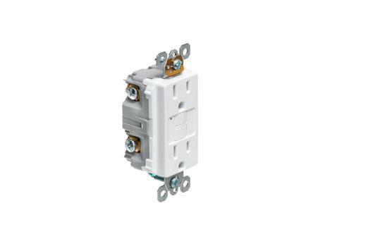
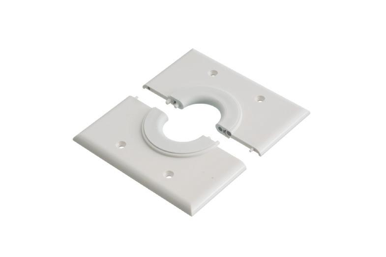
SPLIT WALL PLATES

Arlington’s non-metallic Split Wall Plates provide a simple and effective way to accommodate pre-connectorized low voltage cable(s) of varying size and quantity or pre-existing low voltage cables.
Multiple split grommets are provided with our single- and two-gang wall plates for increased versatility in effectively sizing and covering the hole/opening.
Use as shipped, or with one of the supplied bushings to alter the size of the opening.
• Single-gang CESP1 w/ 1-1/2" opening, bushings for .312" • .500" • 1" openings


bushings for .750" • 1.250" openings

Product info aifittings.com/landing/split-wall-plates

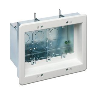
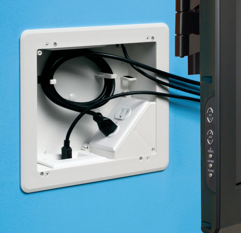
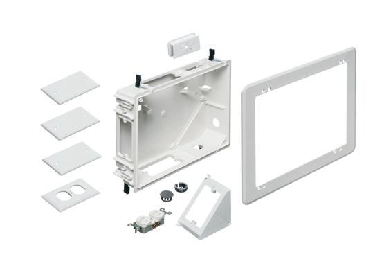
Arlington’s recessed STEEL combination power/low voltage TV BOX® is the best way to mount an LED or Hi-Def TV flush against a wall.
TV BOX provides power and/or low voltage in one or more of the openings. Plugs and connectors stay inside the box, without extending past the wall.
Designed for use in new or retrofit commercial construction where metal raceway is used, we have a STEEL TV BOX for almost any application!
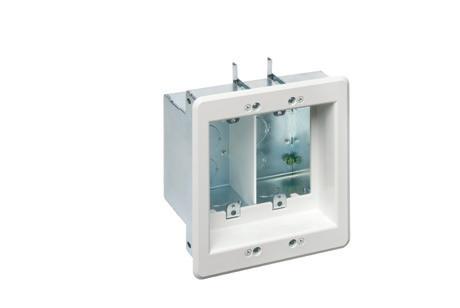

• Steel box; non-metallic paintable white trim plate
• Easy, secure installation
• Optional covers


CESP1 w/ .312" bushing
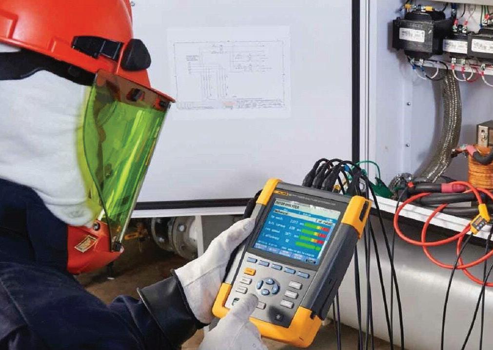
When Equipment Fails Without Warning
How contractors can detect hidden electrical transients
By Jason Axelson, Fluke
Troubleshooting electrical systems often demands more than technical skill — it requires the mindset of an investigator. Issues don’t always announce themselves clearly. Instead, they hide behind symptoms that point in several directions at once: equipment that fails without cause, circuits that seem fine during inspection, or downtime that reappears despite repairs.
When these situations arise, an electrician must combine experience, systematic testing, and the right diagnostic tools to uncover the truth. In this article, we’ll follow one such investigation into a well-maintained manufacturing plant and draw out the lessons every electrical contractor can apply when facing elusive electrical problems.
THE PERSISTENT FAILURE
A contractor has been called in to investigate a large 3-phase motor that has failed multiple times over a three-year span. Each failure had cost the facility significant downtime. Standard steps had already been taken: the motor was replaced, the wiring was inspected, and protective devices verified. Each time, the system looked correct on paper, yet the failures kept returning.
For the contractor, the situation was a classic riddle. If the equipment and installation were sound, what else could be lurking beneath the surface?
THE INVESTIGATION PROCESS
The contractor begins where most failures start — closest to the equipment. Connections are examined, torque is verified, and insulation resistance is tested. No defects are found. Next, attention turns upstream. Breakers, bus connections, and feeders are all checked. Voltage readings appear
normal under load. Power factor and harmonics are evaluated, but nothing out of the ordinary emerges.
At this point, the process turns from routine troubleshooting to detective work. If nothing in the visible system explains the repeated failures, perhaps the problem lies in what can’t be seen with standard meters.
THE UNSEEN ENEMY: ELECTRICAL TRANSIENTS
That’s when the contractor considers electrical transients. These short-duration surges of voltage or current last only microseconds to milliseconds. They can originate from inside the facility (such as motor switching, faulty breaker contacts, or variable-speed drives) or from outside (utility grid switching, capacitor bank operations, or lightning strikes).
Though invisible to the eye and too fast for most instruments to capture, their impact is real. Sensitive equipment
such as PLCs, sensors, and industrial drives can degrade with repeated exposure. Over time, this leads to:
• Premature component failure
• Corrupted data and communication errors
• Costly unplanned downtime
• Higher maintenance expenses
The contractor realizes that specialized monitoring is needed to confirm or rule out transients.
TOOLS THAT REVEAL THE INVISIBLE
Unlike standard digital multimeters or clamp meters, identifying transients requires high-speed power quality analyzers capable of logging and capturing events at very fine resolutions. These tools allow electricians to:
• Capture transient waveforms with sub-millisecond accuracy.
• Measure magnitude, duration, and frequency of each event.

Fluke


up to $26.00
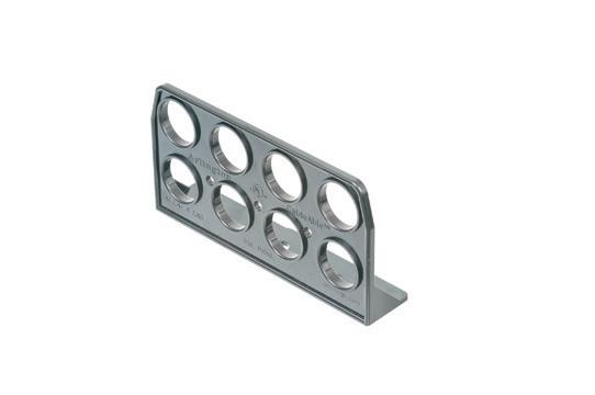
Stacking CableAble Support Brackets on Threaded Rod
• Power, data, communications, control systems
• Plenum applications per NEC 300.22(c)
• Applications with temps from -5°C (23°F) to 90°C (194°F)
• Outdoor use, in wet locations
• Lowering total installed costs
• Minimizing space required for supportand reducing ceiling congestion


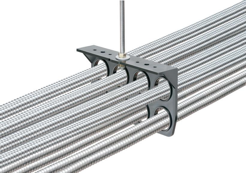
WATCH THE SAVINGS STACK UP with CableAble® Support Brackets... the ONE BRACKET for reliable support of EMT or flexible metal conduit, power MC and NM cables, and low voltage cables, in commercial or residential work, with plenum or non-plenum ceilings.
Four- and eight-hole CableAble mounts horizontally or vertically to studs or unistrut. And horizontally to all thread and beam clamps.


INSIDE PQ
Correlate disturbances to equipment operation (e.g., motor startup, switching).
PQ Newsbeat
If you’re an engineer, commercial or industrial facility manager, or electric utility employee concerned about the quality and reliability of power delivery, this e-newsletter (sent out monthly) is for you.
Topics covered include:
• Power quality
• Voltage sags & swells
• Transients
• Harmonics
• Power factor
• Test & measurement techniques
Subscribe Today
See all of our EC&M e-newsletters at www.ecmweb.com
Distinguish internal vs. external sources by testing at different points in the system.
The contractor sets up the analyzer first at the motor connection, then progressively upstream toward the service entrance. This step-by-step approach systematically narrows in on the root cause of the transient activity, ultimately allowing for the next step to occur: solutioning toward prevention.
BUILDING THE CASE FOR MITIGATION
After several days of monitoring, the contractor has enough data to start piecing together the story. Each captured transient has its own fingerprint — magnitude, duration, timing, and waveform shape. Interpreting these clues points to different sources and, ultimately, different corrective measures.
When the source is internal switching equipment…
The contractor notices sharp spikes each time a large motor starts. These impulsive events are traced back to load switching inside the facility.
Solution: Install transient voltage surge suppressors (TVSSs) at the affected panels and sensitive equipment. These devices act as the first line of defense, clamping the voltage before it can damage controls or drives.
When the pattern shows oscillatory disturbances…
At another point in the system, the data reveals fast, back-and-forth waveforms each time capacitor banks engage. The oscillatory nature of the disturbance suggests resonance within the system.
Solution: Apply line filters or isolation transformers to smooth out the fluctuations and keep them from propagating downstream.
When grounding is the weak link
In reviewing the facility’s bonding system, the contractor finds inconsistent connections that create high-impedance paths. The captured transient events appear amplified compared to their likely source, confirming poor grounding as a contributing factor.
Solution: Improve grounding and bonding practices, ensuring a low impedance return path that reduces both the frequency and severity of transient events.
When the trail leads outside the plant
Finally, some events show up across multiple points simultaneously, with no clear internal trigger. Their timing matches with known utility switching operations in the area.
Solution: Coordinate with the utility provider for a broader power quality review. External sources require collaboration beyond the facility walls to implement utility-side solutions.
By walking through each scenario and applying the right mitigation strategy, the contractor not only resolves the motor failures but also helps the facility strengthen its entire power quality program.
LESSONS LEARNED
Electrical transients are among the most elusive of power quality problems. They don’t appear in normal testing, yet their consequences can be devastating. For contractors, the key lessons from this case are:
• Don’t stop at the obvious. If equipment continues to fail despite replacements, broaden the investigation.
• Use the right tools. Only high-speed analyzers can capture transient events.
• Think systematically. Start at the point of failure and work upstream to localize the source.
• Apply targeted solutions. Mitigation depends on the transient type and origin.
THE TAKEAWAY
Electrical troubleshooting is as much about persistence and process as it is about technical skill. By approaching unexplained failures with an investigative mindset — and by leveraging advanced diagnostic tools — contractors can uncover hidden threats like transients before they cause long-term damage.
Reliability begins with visibility and sometimes seeing what happens in less than a millisecond makes all the difference.
Jason Axelson is a subject matter expert at Fluke specializing in power quality, electrical test equipment, and product applications.


Extra-duty one-piece design
Pre-installed strut clip for faster installation on strut

corrosion-resistant QUICKLATCH® pipe hangers cost the same as a steel pipe hanger with a bolt and nut – but better. They’re faster and easier to install. And SAVE 25 seconds* per installation! • UV rated for outdoor

AROUND THE CIRCUIT
Working Space Requirements for Elevated and Other Nonstandard Equipment Locations
How to ensure a Code-compliant installation of a disconnect switch or circuit breaker located next to equipment installed above an accessible drop ceiling or at a readily accessible location
By Sayed Aasif, C.Engg, and William McGugan, P.E., CDM Smith
This article offers an overview of National Fire Protection Association (NFPA) Standard 70, The National Electrical Code (NEC) minimum requirements applicable to working space and accessibility requirements, considerations for elevated and other nonstandard equipment locations, and a summary of exceptions and requirements related to non-standard locations. Unless otherwise noted, the NEC references in this article are from the 2026 edition of the Code.
GENERAL OVERVIEW OF WORKING SPACE AND ACCESSIBILITY
Most engineers are familiar with NEC basic requirements related to working space as detailed in Sec. 110.26, which applies to spaces about electrical equipment of 1,000VAC or 1,500VDC or less. Fewer may be familiar with sections for equipment of higher voltages (those over 1,000VAC or 1,500VDC) — Sec. 110.32, Sec. 110.33, and Sec. 110.34 — because such equipment is less common than lower-voltage
Fig. 1. Disconnect switch mounted above the ceiling grid with accessible panels.
Courtesy of CDM Smith
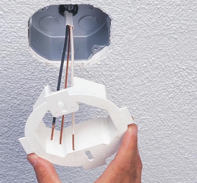
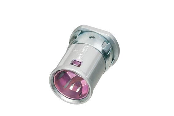
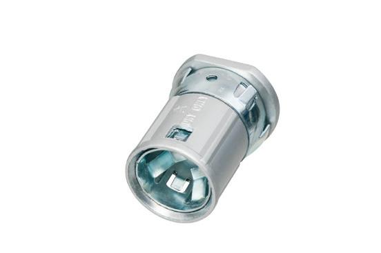
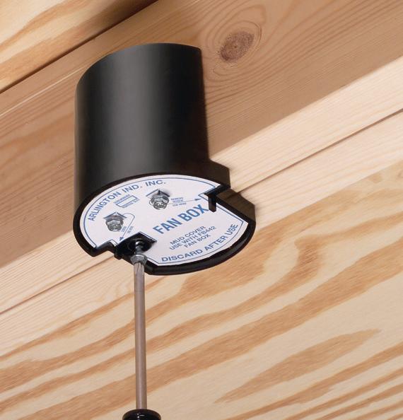
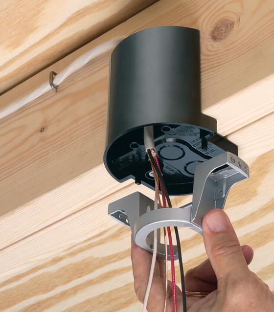
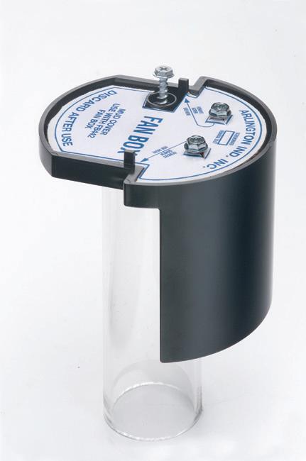
FAN FIXTURE BOX


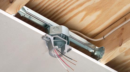
Arlington’s heavy-duty, plated steel fan/ fixture box has an adjustable bracket that mounts securely between joists spaced 16" to 24" o.c.
Flush ceiling installations

FBRS415 is designed for ceilings up to 1-1/4" thick. For 1/2" ceilings, use the pre-bent positioning tab. For other ceiling thicknesses, bend along the appropriate score line.
• 15.6 cu. inch box ships with captive screws, mud cover, installed NM cable connector

sizes – as well as a variety of other products such as timers, disconnects, inlet boxes and more. UV rated, paintable plastic for long outdoor life.
Squared-off corners make them gangable so you can create the mounting base needed for the product you’re installing.


AROUND THE CIRCUIT
equipment. Even fewer engineers may be familiar with Sec. 240.24, Sec. 404.10, Sec. 430.102, and NEC Chapter 6, “Special Equipment,” mostly because of the relative rarity of installing electrical equipment in special situations. Unless otherwise noted, all equipment discussed in this article should be considered 1,000VAC nominal or less.
The NEC provides minimum requirements for equipment installations, not necessarily ideal or even (as many field personnel will attest) adequate spaces, concerning the ability to safely and efficiently perform work. Designers should not only consult the NEC, but also local building codes, utility requirements, and experienced personnel in their design process.
To best understand and apply the NEC sections discussed, the following NEC Art. 100 definitions are provided:
• Accessible: When applied to equipment, “Capable of being reached for operation, renewal, and inspection.”
• Readily accessible: “Capable of being reached quickly for operation, renewal, or inspection without those requiring ready access to take actions such as to use tools other than keys, to climb over or under, to remove obstacles, or to resort to portable ladders.”
In brief, Sec. 110.26 requires electrical equipment of 1,000VAC nominal or less to be installed with a minimum width [Sec. 110.26(A)(2)] of the greater of 30 in. or the width of the equipment, a minimum height [Sec. 110.26(A)(3)] of the greater of 6.5 ft or the height of the equipment, and a depth between 3 ft and 5 ft, depending on the nominal lineto-ground system voltage and the grounded/not grounded conditions and/or the exposure of live parts of the installation [Sec. 110.26(A)(1)].
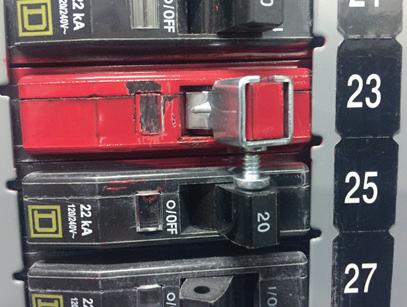
Regarding working space requirements, in terms of where and how equipment may normally be located, the NEC also requires that switches and circuit breakers used as switches be located so that they can be operated from a readily accessible place. Article 404 provides requirements for installing switches, with Sec. 404.10(A) specifically addressing the accessibility and grouping requirements for switches — particularly those used for disconnecting means in electrical installations (see Fig. 1 on page 28).
While the NEC provides a general, qualifiable definition of “readily accessible” in Art. 100, Sec. 240.24 and Sec. 404.10(A) further define and quantify this as “the center of the grip of the operating handle… when in its highest position,” of 6 ft 7 in. or less above the floor or working platform. Exceptions to this height requirement are discussed in subsequent sections of this article.
EXCEPTIONS AND MODIFICATIONS TO WORKING SPACE REQUIREMENTS
As noted previously, there are multiple exceptions and other requirements for equipment installed in locations outside of common locations (e.g., on the floor of an electrical room).
Sec. 110.26(A)(4) relates to equipment installed above lay-in ceilings or within crawl spaces. It provides separate requirements for equipment located in spaces with limited access because of installation or functional requirements. For equipment installed above a lay-in ceiling, the area must be
accessible through an opening that is not smaller than 22 in. by 22 in. For equipment installed in a crawl space, the area must be accessible through an opening that is not smaller than 22 in. by 30 in. Such installations must still have a working space with a minimum width and depth as required by Sec. 110.26(A)(1) and Sec. 110.26(A)(2). However, the height of the working space need only be that which is “necessary to install the equipment.”
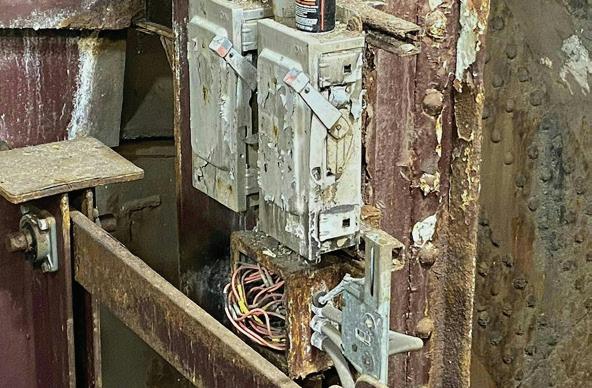
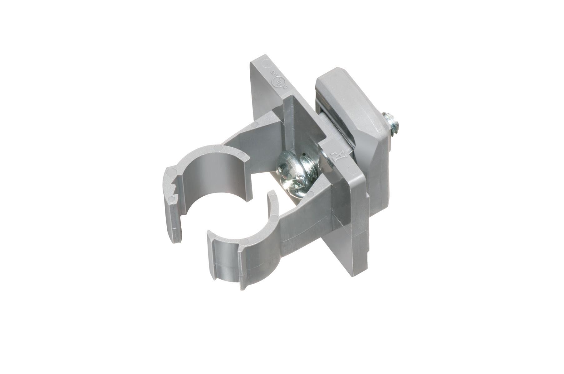
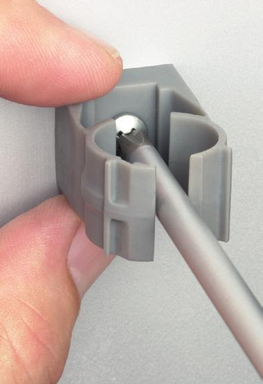
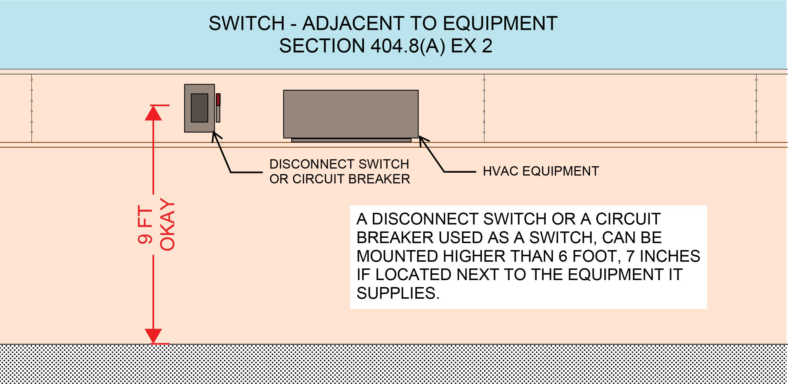
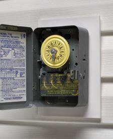
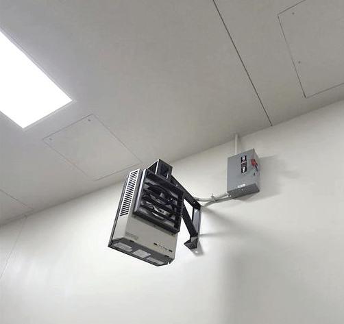
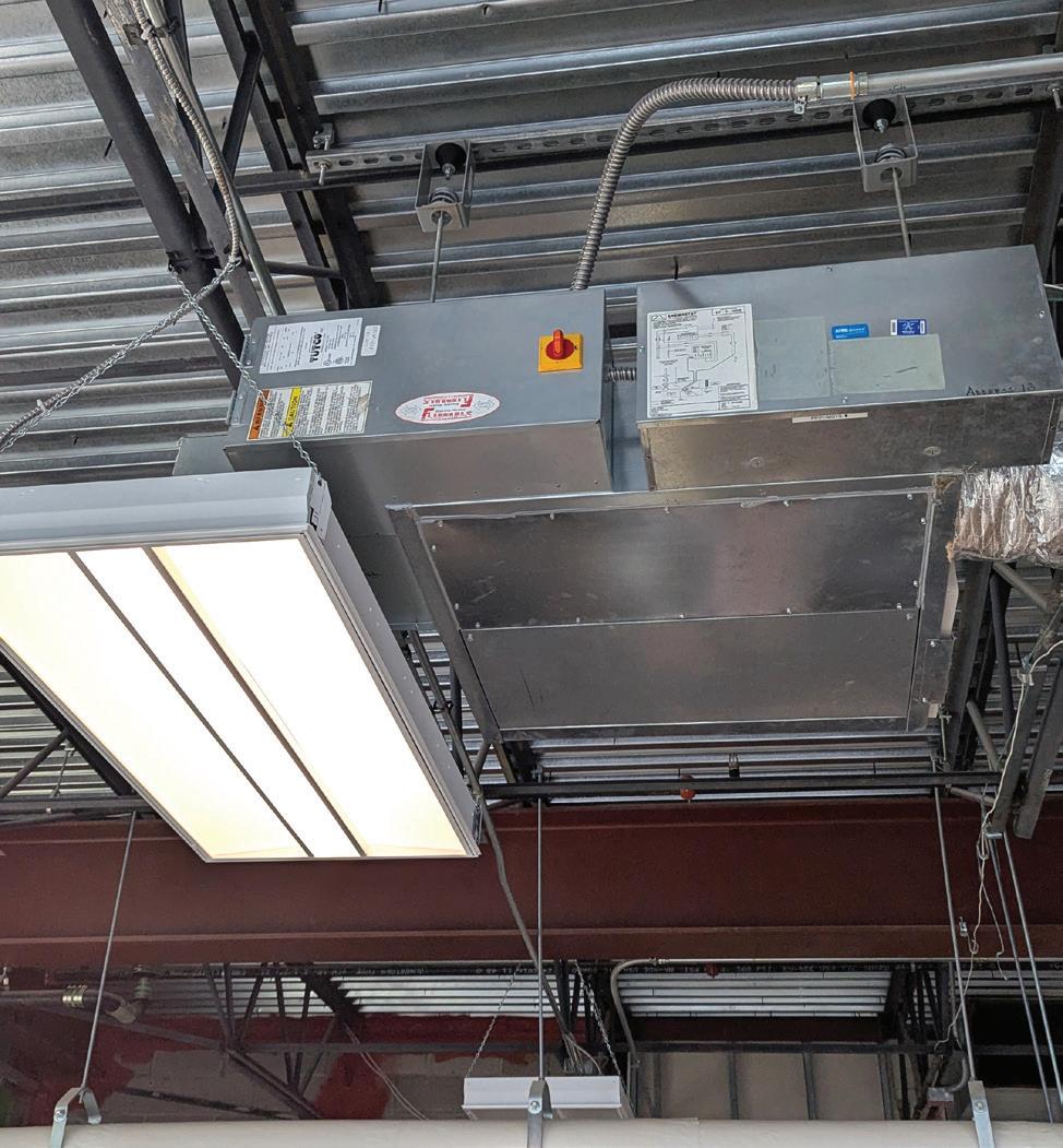
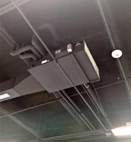
Section 240.24(A)(4) and Sec. 404.10(A), Exception No. 2 relates to equipment co-located with utilization equipment. They permit devices adjacent to the utilization equipment they supply to be mounted higher than 6 ft, 7 in. and accessed by portable means. This means if a device is near the equipment it protects, it does not necessarily have to be permanently and readily accessible; portable access, like a ladder or lift, is acceptable. This clause provides flexibility in installations where permanent accessibility might be impractical, as long as the device is still reasonably reachable when needed (Photo 1). These NEC Articles provide flexibility for installations in non-standard locations, such as above accessible drop ceilings or in elevated positions. It allows switches and circuit breakers used as switches to be mounted above the standard height of 6 ft, 7 in., provided they are installed adjacent to the equipment they serve and are accessible by portable means (e.g., ladders). This exception is especially relevant in scenarios where aesthetics or space constraints necessitate overhead installations. Understanding and applying this provision ensures Code compliance while accommodating practical design and architectural considerations (Photo 2 on page 32).
Sections 240.24(A)(1), 368.17(C), and 404.10(A)(1) relate to busways. Busways in industrial installations are often installed well above the working floor, with overcurrent devices for feeders and branch circuits mounted on the busway itself. Section 404.10(A)(1) permits overcurrent protective devices of busway installations to be located at the

Photo 1. Disconnect switch co-located with heater.
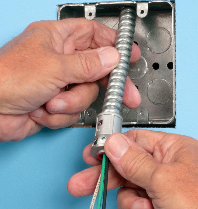
SNAP2IT® CONNECTORS

17SAVE seconds
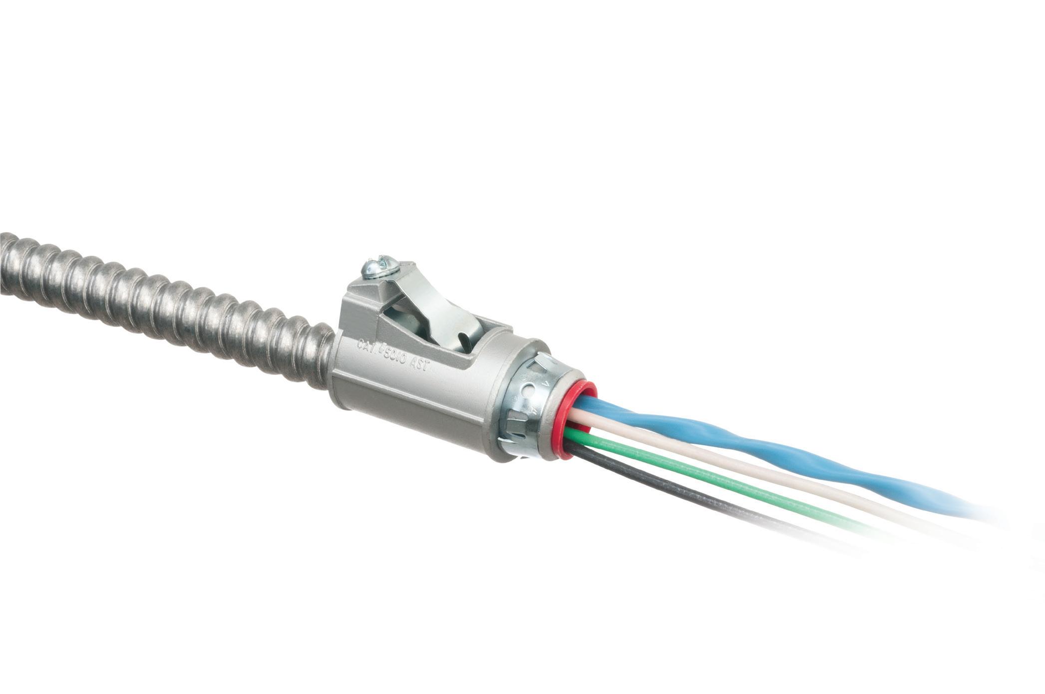
Fully assembled, SNAP2IT® fittings handle the widest variety of MC cable AND THE NEW MC-PCS cables.

Compared to fittings with a locknut and screw, you can’t beat these snap in connectors for time-savings!


LISTED SNAP2IT ® CONNECTORS FOR NEW MC-PCS CABLE ...lighting & low voltage circuits in the same cable


• Fits widest range and variety of MC cable 14/2 to 3/3
AC, MC, HCF, MC continuous corrugated aluminum cable and MCI-A cables (steel and aluminum)...including the new MC-PCS cable that combines power and low voltage in the same MC cable
ANY Snap2It Connectors LISTED for MC cable are also LISTED for MC-PCS cable! These products offer the greatest time-savings.
• Fast, secure snap-on installation
• Easy to remove, reusable connector From cable Loosen screw on top. Remove connector from cable. From box Slip screwdriver under notch in Snap-Tite® Remove connector.


Easy to Snap into Box!
AROUND THE CIRCUIT
same level as the busway. Section 368.17(C) permits such an arrangement provided the disconnecting means can be operated via “suitable means such as ropes, chains, or sticks” [Sec. 368.17(C)].
Additional exceptions to Sec. 240.24, specifically Sec. 240.24(A)(2) and Sec. 240.24(A)(3), provide other overcurrent protective device exceptions in situations where the overcurrent protective device on the line side of a circuit is not readily accessible or the overcurrent protective device is not required by Code.
Section 240.10 does not require supplemental overcurrent protective devices used for luminaires, appliances, and similar equipment to be readily accessible.
Section 225.40 and 230.92 require branch-circuit overcurrent devices to be installed on the load side of a circuit in a readily accessible location, if fed from a feeder or service overcurrent protective device that is not readily accessible. When located on the load side, the overcurrent protective devices must be of a lower ampere rating than the corresponding overcurrent protective devices on the line side.
ADDITIONAL REQUIREMENTS AND EXCEPTIONS
Chapter 6, “Special Equipment,” provides additional requirements for certain types and installations of electrical equipment. Examples include:
• Article 600, Electric Signs and Outline Lighting. Section 600.21(D) requires a minimum working space of 3 ft by 3 ft by 3 ft for certain types of equipment related to electric signs and outline lighting.
• Article 610, Cranes and Hoists. Sec. 610.57 requires a minimum working space dimension of 2.5 ft be maintained in the direction of access to live parts that may
need examination, adjustment, servicing, or maintenance while energized.
• Article 646, Modular Data Centers. Section 646.19 permits the working space and entrance/egress requirements to be modified if specific listed exceptions are met. While Sec. 430.102 does not provide requirements related to working space around motor protective devices, it provides other related requirements, such as that a disconnecting means be located in sight of the driven equipment unless certain exceptions are met.
SUMMARY
In general, the NEC requires electrical equipment to be located such that it has a minimum working space of approximately 30 in. wide (or the width of the equipment), 6 ft, 6 in. high, and 3 ft to 5 ft deep, and requires that switches and overcurrent protective devices be located no higher than 6 ft, 7 in. However, exceptions abound. Where equipment is installed adjacent to the equipment it supplies (e.g., ceiling-mounted heating, ventilation, and air-conditioning equipment; equipment installed in specific locations with irregular access), the NEC permits alternative working space dimensions and installation criteria.
Sayed Aasif, C.Engg is part of the electrical and licensed Institution of Engineers’ Chartered Engineer based in India, specializing in water, commercial, industrial, and substation industry, with experience on various U.S. projects.
William McGugan, P.E. is an electrical engineer with more than 10 years of experience in power electrical engineering, including the design, maintenance, and analysis of power systems for municipal, commercial, industrial, and federal projects.
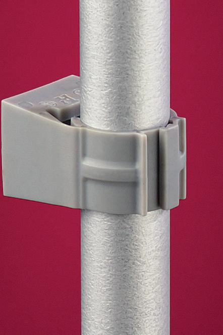
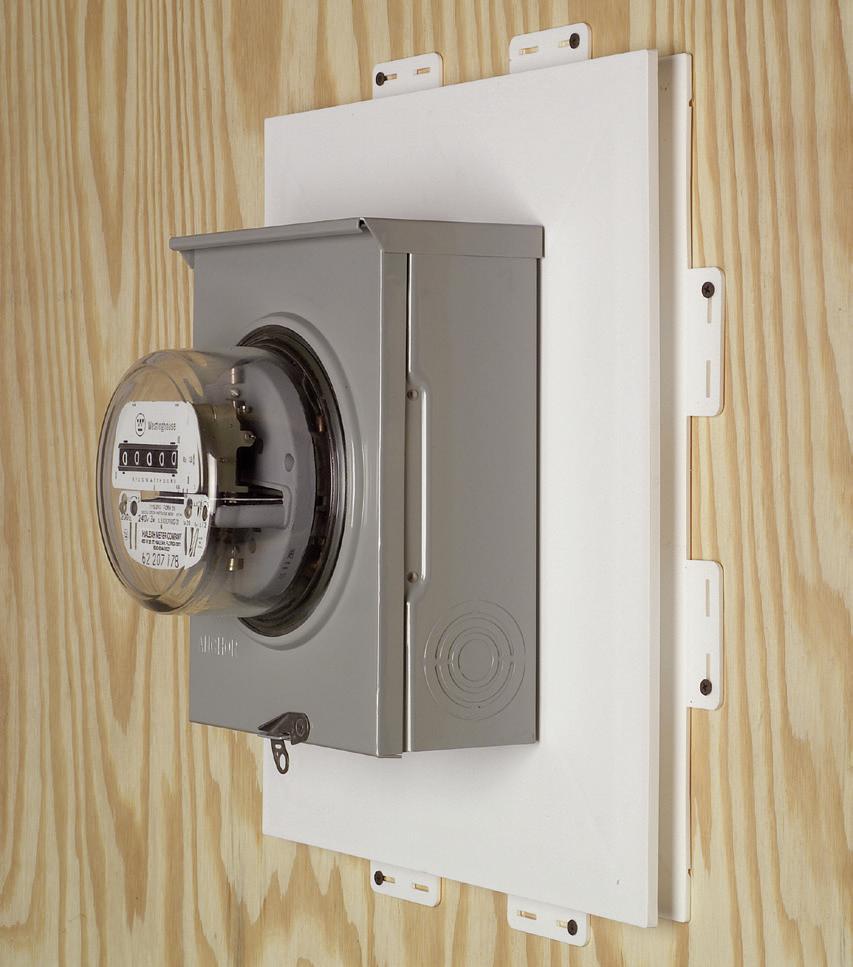
Photo 2. Disconnect switches mounted in elevated positions.
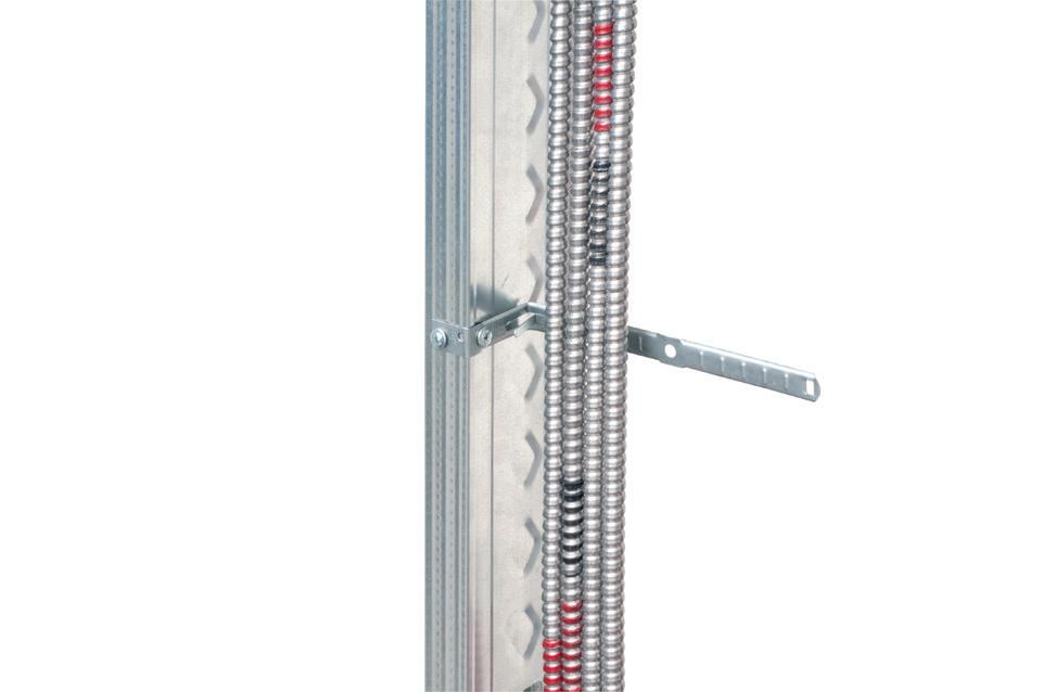
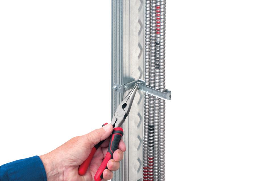
CABLE SUPPORT
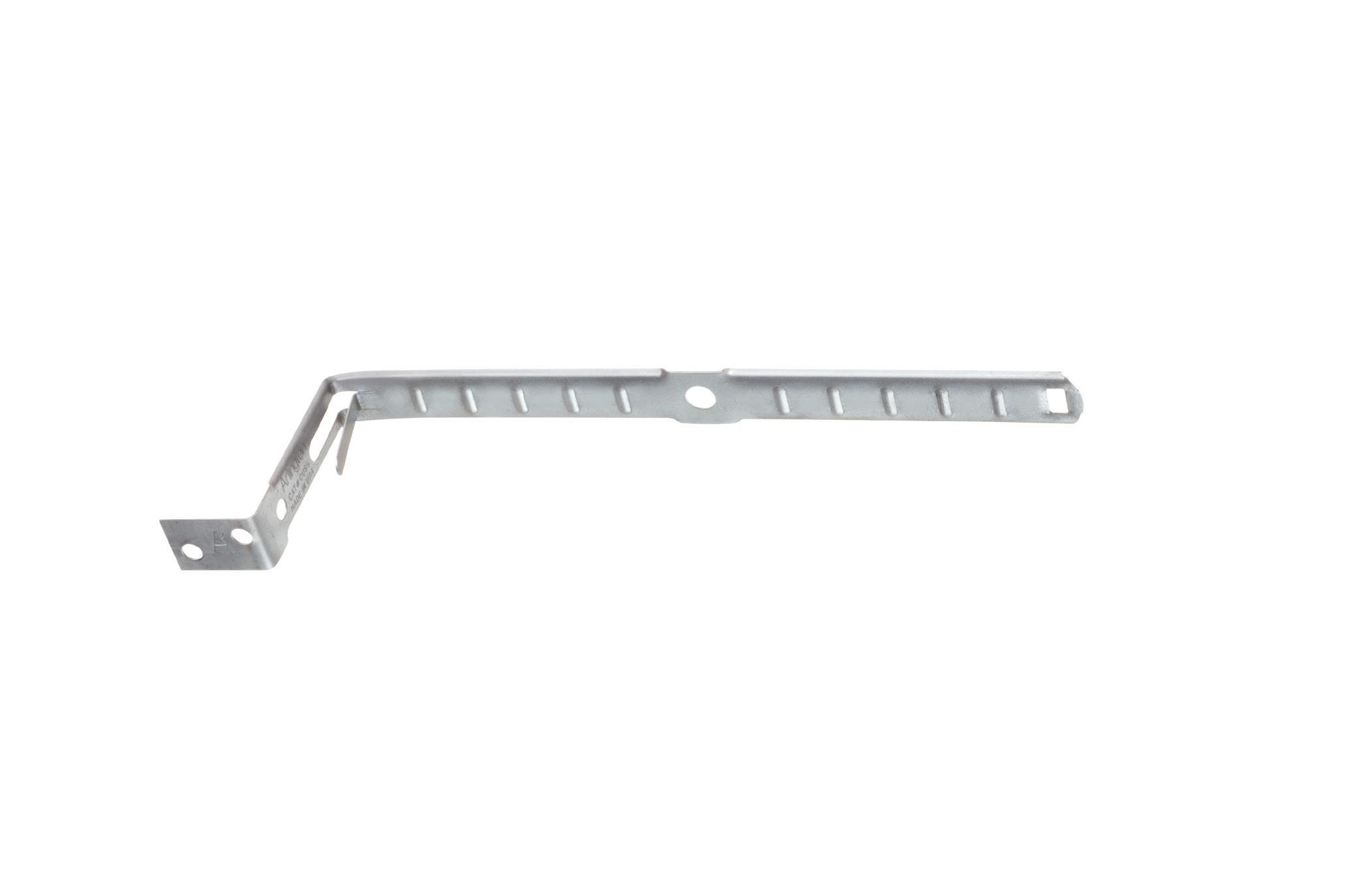
Arlington’s economical CUS6 galvanized steel Cable Support holds cable secure and centered on a metal or wood stud.
It’s perfect for fastening and individual metal clad cables –or six NM cables on a 2x4. to a wood or metal stud, and position the cables. Next bend the strap at the foldline (centerline). Fold the strap over the cables and insert the locking tab in the opening as shown to hold


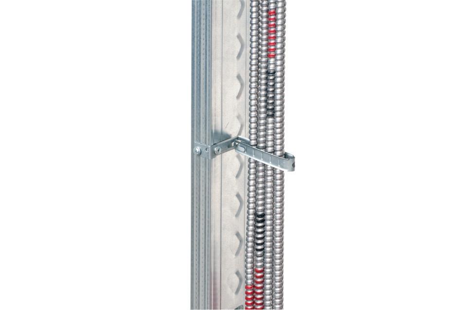
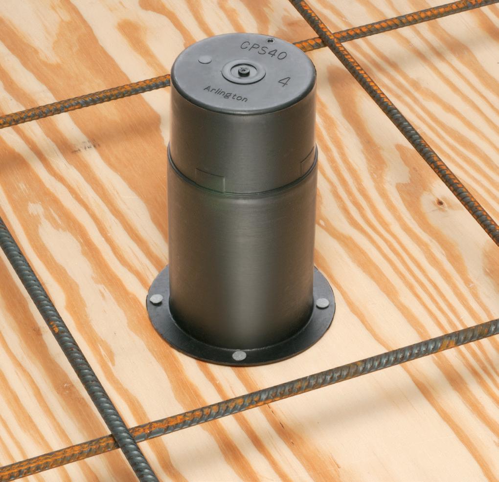
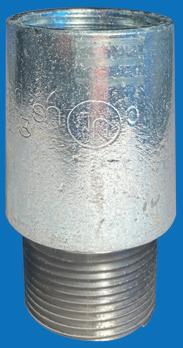
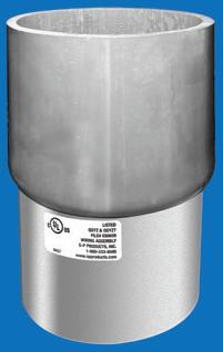
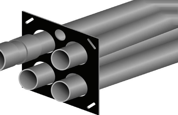
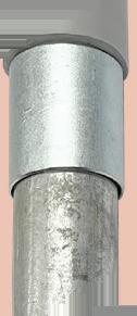
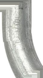
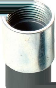
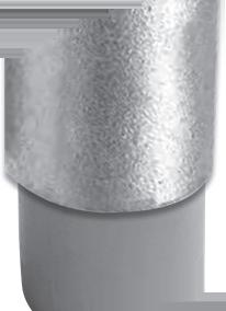
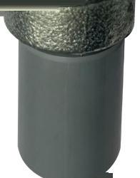
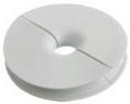
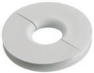
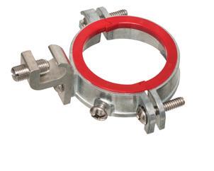
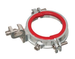
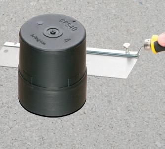
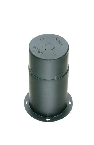
Arlington’s Concrete Pipe Sleeves are the economical way to sleeve through concrete pours in tilt-up construction WALLS – and FLOORS allowing cable and conduit to run easily from one floor to the next.
No costly core drilling – No cutting holes in the form. Plus, you can position the hole prior to pouring the concrete.
• Attaches to form with nails or screws
• Stackable up to 23" h for extra deep pours
• Vents keep wet pipe sleeves from sticking together
• Multiple hole sizes: 1-1/2"
2"


Selecting The Right Motor Control Centers for Mechanical Applications
Learn how MCCs centralize motor management, improve safety, enhance maintenance processes, and provide cost savings.
By Elizabeth Whelan, Current Midwest
Motors drive the equipment that keeps production moving in any industrial or mechanical operation. Managing those motors effectively requires wiring them to power sources — and also calls for a structured system that can protect and control them. That’s the role of a motor control center (MCC).
MCCs consolidate electrical components (motor starters, circuit protection, and control devices) into one central unit, providing a safer and more efficient way to handle multiple motors in a facility.
Selecting the right MCC for your facility means looking beyond the basics. Consider factors such as load requirements and environmental conditions. It also requires you to ensure compliance with industry standards and stay within a budget.
These factors all influence long-term performance and safety while also providing better cost efficiency for your business.
WHAT DOES A MOTOR CONTROL CENTER DO?
An MCC serves as the main hub for managing multiple electric motors in one location rather than separately. It’s responsible for controlling and distributing power to motors that keep your equipment running smoothly while also protecting motors from damage and reducing hazards. MCCs include several components, such as:
• Motor starters
• Circuit breakers
• Variable-frequency drives (VFDs)
• Other control devices

The role of a motor control center (MCC) is to consolidate electrical components into a central unit, allowing for safer and more efficient management of multiple motors in a facility.”
LISTED BOX EXTENDERS

Arlington’s variety of cULus Listed Box Extenders extend set back electrical boxes up to 1-1/2".
Made of heavy-duty, 105°C continuous use 94V0 rated, flame retardant plastic, they level and support wiring devices, while protecting wires against damage and stripping.
Choose the one that’s right for you!
BE1, BE2, BE3, BE4...Single-, two-, three- and four-gang, and BE1R for round or octagonal boxes...
Box Extenders


device support in oversized or mis-cut wall openings, available in single-, two-, three- and four-gang, (patented BE1X, BE2X, BE3X, BE4X.)
Our new heavy duty, COMMERCIAL-GRADE steel support plate! As shipped, single and two-gang BE1XLS and BE2XLS work with maxi cover plates, but they’re and standard plates. Convenient. Saves time. Great for poorly cut drywall.
For all standard devices, switches and GFCIs, our box extenders comply with NEC Article 314.20 for set back boxes.


MOTOR FACTS
All these components work together to keep motors functioning safely and with better efficiency overall.
Many industries use MCCs. Examples include manufacturing, oil and gas, water treatment, HVAC, and material handling. Centralizing motor management offers facilities within these industries a reliable, streamlined way to maintain productivity and keep operations and processes on track.
BENEFITS OF USING MCCS IN YOUR FACILITY
Here are reasons to consider utilizing MCCs:
• Management and monitoring in one place. MCCs offer a centralized way to oversee management remotely for some or all motors in a facility as needed. This helps reduce the need for installing and maintaining extra equipment throughout buildings, such as running extra wiring.
• Better safety. These enclosures come with their own protective measures, keeping motors, bus ducts, and other connected equipment, and staff safe. These built-in features help lower the risk of electrical-related hazards that may result in dangerous or costly accidents.
• Easier troubleshooting and maintenance. Having a main hub for managing motors helps simplify maintenance, enhancing the ability to keep all components and equipment in optimal condition. MCCs also make it easier to detect problems early and address them right away, reducing the need for repairs and downtime.
• Greater efficiency. MCCs help improve motor performance, resulting in more efficient energy use via VFDs and other devices.
FACTORS TO CONSIDER WHEN CHOOSING AN MCC
Industry standard compliance. Selecting an MCC that meets industry standards and ratings, along with any applicable regulations, ensures compliance. A few organizations set requirements or provide ratings for performance and safety in different conditions, such as:
• National Electrical Manufacturers Association (NEMA)
• National Electrical Code (NEC)
• American National Standards Institute (ANSI)
• International Electrotechnical Commission (IEC) for international compatibility
Short-circuit protection. Sudden faults can result in motor failure or other damage and disrupt operations. Choosing an MCC with protective devices that guard against short circuiting, such as fuses, relays, and circuit breakers, helps reduce these risks.
Integration capabilities. The right integrations with automation systems provide seamless functioning and
Selecting an MCC that meets industry standards and ratings, along with any applicable regulations, ensures compliance.
enhance performance and safety. Look for an MCC with the ability to connect with programmable logic controllers (PLCs) and supervisory control and data acquisition (SCADA) systems or other automation platforms as needed.
Load requirements. Consider the demands of individual motors and overall facility load when choosing an MCC. This helps ensure that it can handle peak operating conditions without becoming overheated or overloading. Selecting the right size reduces risks, such as premature wear and tear and unexpected failures.
Scalability. Keep operational needs and business growth in mind for MCC selection. A motor control center that meets current operating conditions may not be able to handle increases or expansions, resulting in the need to replace it. To avoid this, choose an MCC design that offers scalability as conditions shift, such as modular designs.
Environmental conditions. MCCs vary in terms of the environmental factors they’re built to withstand. Depending on facility type, you may need to consider conditions, such as:
• Dust
• Humidity and moisture exposure
• Temperature
• Chemical exposure
• Vibration
Look for an MCC that has the appropriate NEMA rating for enclosures to ensure protection against environmental hazards. This helps lower the risk of damage or failure, while also keeping maintenance costs lower and protecting staff.
Basic and advanced control options. Consider facility needs when determining which types of control options an MCC must have. Basic options, such as on/off starters, may be suitable when straightforward motor operation is needed. But advanced options, such as digital monitoring and remote access, may offer more convenience while also enhancing efficiency and performance. Initial and life-cycle costs. Choosing an MCC with a budget in mind involves more than comparing upfront pricing. Factor in maintenance, energy usage, and other life-cycle costs. A lower initial cost may result in higher costs over time due to higher energy consumption or incorrect sizing that causes more wear and tear. Investing in an MCC with advanced features and capabilities may help offset the initial cost and provide years of reliable performance.
IMPROVED SAFETY, EFFICIENCY, AND COST SAVINGS
Selecting an MCC that’s suitable for your facility may not be a quick decision. But taking the time to choose based on key factors and considerations helps ensure you install a motor control center that fits your facility’s needs — from environmental conditions and load requirements to your budget. The result is a safer working environment and increased productivity — along with cost savings.
Elizabeth Whelan has been with Current Midwest since 2018 in the role of marketing manager.
SNAP2IT® CONNECTORS
Arlington’s new one-piece RETROFIT SNAP2IT® fittings are easy to use in an OLD WORK installation, and handle the widest variety of cables! They’re ideal for adding additional circuits to a load center. And you get the same labor-savings in a retrofit installation!
Easy snap-in installation - NO TOOLS. Install connector into the knockout in an existing box, pulling cable/conduit through the knockout. Slip the fitting onto the cable, then snap the assembly into the box. That’s it... a secure installation with no pullout
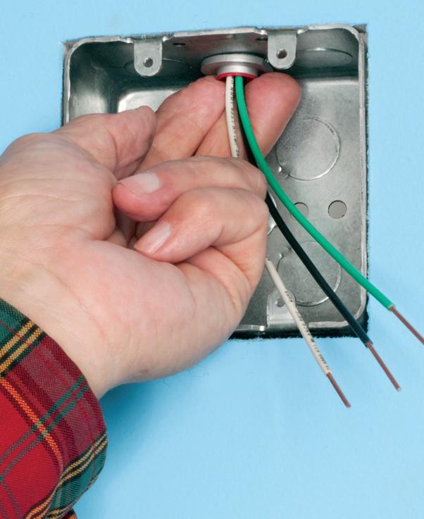
Widest total cable ranges 14/2 to 10/3
Widest variety of cables AC, MC, HCF, MC continuous corrugated aluminum cable, MCI-A cables (steel and aluminum), AC90,
Super-secure


The box adjusts to fit wall thicknesses from 1/4" to 1-1/2". Mounting wing screws hold it securely in place.
•
• Low voltage side has a combo 1/2" and 3/4" KO for raceway
• Includes NM cable connector (power side)
By Aaron Szymanski, Augmenta
Stop Inheriting Other Trades’ Problems
How AI-powered routing and coordination can eliminate weeks of coordination rework
When electrical contractors (ECs) start most projects, they’re already behind schedule. Their work is, by nature, one of the final pieces in the building puzzle. Electrical work is expected to fit perfectly around the complex structural, mechanical, and plumbing systems already in place. As a result, ECs inherit the cumulative friction of every design misstep, spatial conflict, and scheduling error that occurred upstream. Poor
project coordination — the root cause of this last-minute friction — is to blame, and it has major consequences on every EC’s bottom line.
According to the general contractors (GCs) that employ ECs, successful trade coordination is critical to success. In fact, research shows it’s what enables 71% of projects to finish on time and 76% to be completed within budget. Yet, the reality is that one-third of GCs face on-site quality challenges from poor coordination, which inevitably cascades into schedule delays, costly
rework, uncomfortable conversations, and significant profit erosion across the trades. This friction is one of the industry’s greatest choke points, leading to losses estimated at more than $17 billion annually.
For the EC, poor coordination translates into a labor and material disaster. An unexpected change in mechanical ductwork or a relocated plumbing pipe can force ECs to rework their entire electrical routing, all while the clock and the labor budget run out. This cycle accelerates and is amplified on the large-scale,
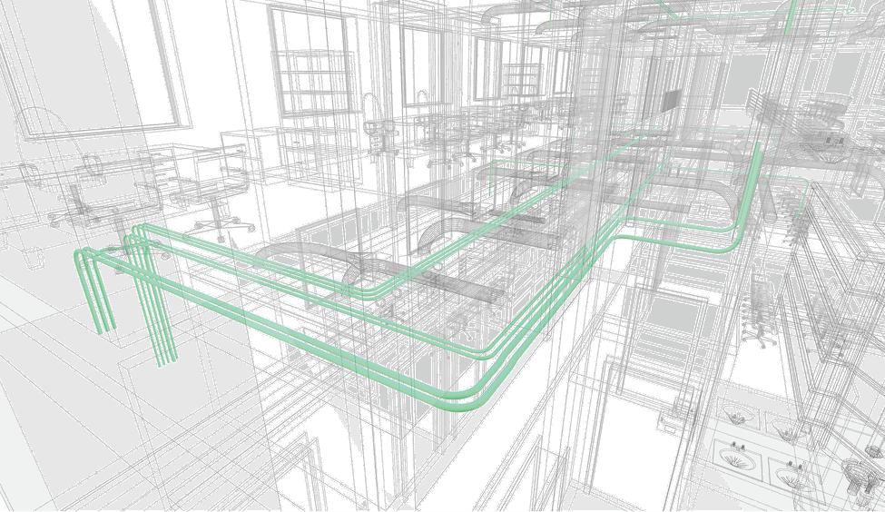
With advancements in AI, important information like relevant specifications and building codes, the spatial constraints and preferences of the site model, and the fabrication requirements (from conduit spacing and bend angles to support preferences and rack sizing) can be incorporated into the design.

mission-critical projects that often need to accommodate frequent design changes and demand zero margin for error.
The path to regaining control lies in reimagining pre-construction coordination. By embracing technology that moves beyond single-trade mindsets, electrical contractors can have their voices heard earlier in the process, resulting in a collaborative pre-construction design process that enables a clash-free path from the start. This approach gives ECs unprecedented control over the process from prefabrication to the grand opening.
THE FRAGMENTATION TRAP
The fundamental challenge here is that most construction projects begin in fragmented silos. Trades work in isolation, pass their models along, and hope the final assembly works — this is how it’s always been done. This siloed approach immediately forces subcontractors into a zero-sum game, leading to trades constantly fighting for space within a building.
Computer-aided design (CAD) and building information modeling (BIM) have improved the process. Electrical teams have come to appreciate these as ways to better manage project complexity, but, while helpful, their impact
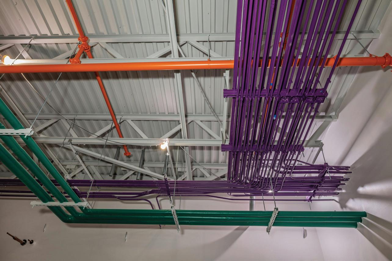
Poor project coordination with other trades adversely affects project scheduling, causing teams to spend excessive time at their computers rather than installing conduit.
has been somewhat limited. BIM, for example, has been invaluable in aggregating and accounting for all relevant information/data in a construction process. It can account for a massive amount of project data, and can flag when two systems are going to occupy the same space. It is not, however, an active problem solver, leaving ECs to manually resolve conflicts — a process that can
take weeks, both in front of a computer and on site.
When a potential conflict is flagged, ECs oftentimes wait for notoriously contentious multi-trade coordination meetings, then manually go back into the models and spend weeks reconsidering new raceway design options, and finally re-coordinate with the GC and other trades. This clunky process is a
massive friction point, costing valuable pre-construction time. As a result, accurate project scheduling is nearly impossible, and teams are forced to spend excessive time at their computer rather than installing conduit on site. It’s time to find a better way.
DESIGNING THE WAY OUT OF CONFLICT AND INTO PREDICTABILITY
The solution is a fundamental shift in philosophy that moves construction design closer to the automated, rulebased efficiency found in advanced manufacturing. This can be achieved through the introduction of spatial AI in the design process.
Instead of using AI to document a single design idea, ECs are now empowered to use technology advancements to become an active hand in problemsolving. These new solutions can feed all of the important context of a project: the relevant specifications and building codes, the spatial constraints and preferences of the site model, and the fabrication requirements — from conduit spacing and bend angles to support preferences and rack sizing. Then, they process countless design possibilities and rapidly generate a set of optimal design alternatives. Without manual coordination, this technology incorporates the key considerations for the design of the entire building (electrical, mechanical, structural, and plumbing) simultaneously.
The output is a constructible, codecompliant design that is not only clash-detected but also clash-free from the start. For the EC, this is a transformational difference. With this technology, the project handoff is not a suggestion that requires weeks of manual rework; it is an executable roadmap.
IMPACTS OF BUILDING A PREDICTABLE PROJECT
A clash-free design delivers immediate, tangible benefits to the EC’s bottom line and operational capabilities, including:
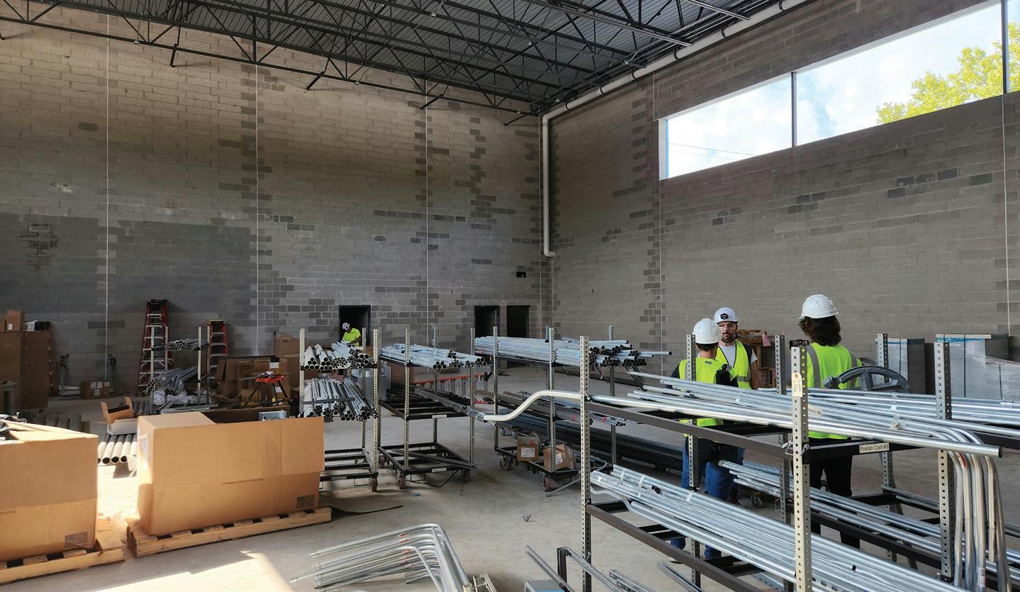
• Improved time-to-execution: By eliminating the multi-week coordination gridlock, ECs can move directly to detailing and prefabrication. The design is a final, constructible plan that reduces project volatility.
• Accurate sub-trade pricing: An AI-optimized design accounts for all materials with precision, eliminating the costly contingency that must be built into estimates to account for field-level design changes. This predictable cost structure stabilizes profit margins.
• Maximized off-site prefabrication: When the correct electrical pathway is guaranteed, ECs can confidently maximize off-site fabrication of assemblies and racks. This eliminates pre-construction design risks by transforming high-cost, high-risk field labor into controlled, high-efficiency shop work that boosts profitability, safety, and quality.
before they happen, transforming the role of the EC.
This technology is not intended to replace electrical professionals. With automation handling the massive, months-long effort of design coordination and conflict resolution, ECs are freed to take on higher-value, projectmanagement-focused roles. These leaders can then orchestrate the job from a technical standpoint and manage the critical human elements — the reasoning, negotiation, and on-site nuances. This transition grants ECs the time to focus on adding additional value for their clients.
AI-powered generative design will allow the construction industry to
When a issues arise on a job site, electrical contractors often must wait for multi-trade coordination meetings, which inevitably leads to them having to manually go back into the models and spend weeks reconsidering new raceway design options.
• Scalability for high-margin services: With AI automating low-level, high-friction work, design teams gain a tremendous productivity boost. This enables EC firms to confidently take on more complex projects and capture more revenue per project, evolving from a subcontractor to a core design partner.
THE CONNECTED BUILDER: LIBERATED TO INNOVATE AND CREATE VALUE
Coordination issues are the clearest signal of an inefficient process. By unifying the trades earlier in the preconstruction process, AI-powered generative design stops bottlenecks
move away from an outdated system of constant conflict resolution and toward a collaborative model with integrated project delivery. As a result, the EC can focus its expertise on technical mastery and high-value installation, liberated to innovate and help create structures that are built on time, under-budget, and more sustainably by default.
Aaron Szymanski is a co-founder and head of product at Augmenta. He leads Augmenta’s product definition and design efforts, bridging the gap between computational science, artificial intelligence, and the needs of users and organizations within the AEC industry.
Augmenta
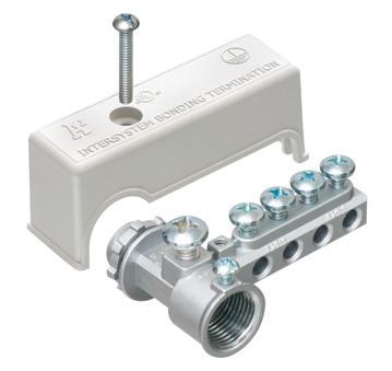
GROUNDING BRIDGE
MULTIPLE ZINC & BRONZE STYLES MEET NEC GROUND

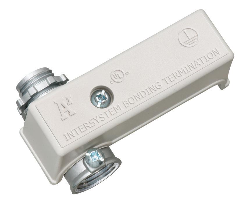


Arlington’s heavy-duty Grounding Bridges provide reliable intersystem bonding between power and communication grounding systems. And handle multiple hookups of communications systems: telephone, CATV and satellite.
Our new GB5T comes with a Combination Threaded and Set-Screw hub for Threaded Rigid – or EMT Conduit.
Arlington’s zinc and bronze grounding bridges...
• Four termination points; more than required by the NEC
• Meet 2020 NEC bonding requirements for 250.94
• Fast, simple installation indoors or outside
• Textured, paintable plastic cover (except GB5NC)


• Easy access for inspections


Inside the Electrical Industry’s AI Learning Curve
As electrical firms ramp up their use of artificial intelligence, some trends are emerging in why, where, how, and for whom.

By Tim Kridel, Freelance Writer
One day soon, you’ll catch yourself telling interns and apprentices, “Before we had AI...,” just like Ryan Elbert reminisces about a time when there wasn’t even a computer on his desk — let alone one connected to the internet and the cloud and running AI. He wasn’t replaced by a computer, and it’s unlikely that you’ll be replaced by AI anytime soon. Why? As powerful as it is, AI is still just a tool — one that’s far better at answering questions rather than knowing what to ask.
“We see AI as a powerful tool, but its true value is realized when used by skilled technical professionals,” says Elbert, a Black & Veatch executive vice president and global director of engineering and development services. “While it can be used to automate repetitive tasks and streamline workflows, having a human in the loop is


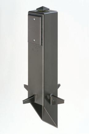
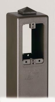
Arlington’s Gard-N-Post® enclosures and supports offer the attractive, safe, and easy way to install a light fixture and/or one or two devices outdoors!
• Non-metallic, heavy-duty UV rated plastic
• Damage resistant
• No chipping... 4 permanent colors
• GARD-N-POST... a variety of styles, 9" to 73" tall


really essential, especially when it comes to construction and design.”
In electrical, AI use cases run the gamut, from producing multiple iterations of a design to creating slide decks to present those design options to a client. A common denominator — and a big part of the business case — is that AI does grunt work that otherwise would tie up highly skilled employees.
“A lot of our integration has been using Copilot to simplify routine tasks and enable our professionals to devote more time to higher-value work,” Elbert says. “I’ve used it to turn emails into PowerPoint presentations. It’s really useful for people like me to increase our skills and utilize Excel more effectively.”
Henderson Engineers is using AI for automating design work in some cases and optimizing it in others. An automation example is AI creating a basic design using criteria for where to place receptacles, luminaires, and Ethernet drops in a room full of workstations. An optimization example is having the AI analyze multiple design iterations to pinpoint the one that best meets the client’s requirements.
“If they said, ‘Optimize this for cost,’ you might get something that was easier to build, faster to build, and reduced labor,” says Dustin Schafer, CTO.
Although ChatGPT made AI an overnight sensation when it was released in November 2022, it’s just one type of AI: generative, which means it uses raw materials such as text and images to create things such as the design for an electrical raceway or a PowerPoint deck. Some electrical firms have been using other types of AI for longer.
“Rosendin has been using AI in one capacity or another for the past six years, starting with more traditional AI use cases, like predictive analytics, and leading up to using generative AI in its current form starting in late 2022,” says Jad Chalhoub, senior director of innovation. “We have also deployed a lot of automation software that I wouldn’t necessarily classify as AI, but that has had massive impacts on repetitive tasks.”
NO SILVER BULLET
Black & Veatch, Henderson, and Rosendin are part of a trend in the overall
construction and engineering (C&E) sector. According to a 2025 survey of more than 300 senior C&E executives, 91% plan to spend even more on AI in 2026. Another, larger survey conducted by the same company — IFS, which specializes in industrial AI software — found that 58% of those in C&E were creating departments dedicated to implementing AI.
“One thing I would like to point out is the importance of focusing on incremental enhancements,” Chalhoub says. “We are not looking at a silver bullet solution, but rather at utilities that will make [something] 1% better, over and over again.”
Henderson also isn’t looking for a silver bullet.
According to a 2025 survey of more than 300 senior C&E executives, 91% plan to spend even more on AI in 2026.
“It doesn’t do everything, but it does a few things really well,” Schafer says. “There are 2,000 places you could apply those few things and have a big impact. We’re focused on the orchestration of existing workflows and calculations.”
As EC&M explored in a June 2024 article, “Is AI the Future of BIM?”, chatbots and other AI-powered tools can serve as a user interface for multiple software platforms and databases. This also helps minimize hallucinations, where AI basically makes up responses to compensate for incomplete information and prompts.
“We have a lot of design tools and a lot of design standards, and we’re starting to use agents to orchestrate those automations in a way that gives us deterministic outputs,” Schafer says. “It reduces the hallucinations. We’re not counting on the agents to give us an answer. We’re using the agents to sit between the users
and the tools to automate streams of calculations so we can do things faster but still get the same good answers we were getting before.”
This is another example of why AI is unlikely to eliminate skilled jobs.
“You really have to have a human in the loop that understands exactly what the design requirements are and how you get to the right answers to validate what AI generates,” Elbert says. “That’s what our licensed engineers do. They have to understand the math and the theory behind the output. The other challenge is the codes and standards. There’s so much interpretation that has to be done. That’s best done by a human.”
Like any other tool, AI’s effectiveness depends on the skill of the people using it.“There aren’t a lot of buttons to learn like traditional software, but knowing how to talk to AI and what to expect out of it is incredibly important to harness its power,” Chalhoub says.
Black & Veatch agrees.
“We’ve learned that effective prompting and experimentation are really the key to unlocking its true potential,” Elbert says. “To become successful in AI, I encourage professionals to share prompt strategies, to collaborate, and even leverage AI to build stronger prompts. You can ask it to help you with prompting.”
DIY PROFESSIONALS
There’s a large selection of off-the-shelf AI tools for general business applications. They’re useful for many electrical use cases, but other applications require AI with industry-specific capabilities.
“A lot of the processes in electrical construction are similar to other office jobs, and leveraging the abundance of tools available for these applications is as important as finding tools for the niche use cases of electrical construction,” Chalhoub says. “We are actively working with a number of providers and startups working on electrical-construction-specific AI tools that we are hoping will address these niche needs.”
Sometimes those niche needs are best met with a tool developed in house.
“There’s no off-the-shelf option that works because all of [our] calculations are proprietary,” says Henderson’s
FOR NEW CONCRETE FLOORS
Side connections lock single gang FLBC8500 boxes together
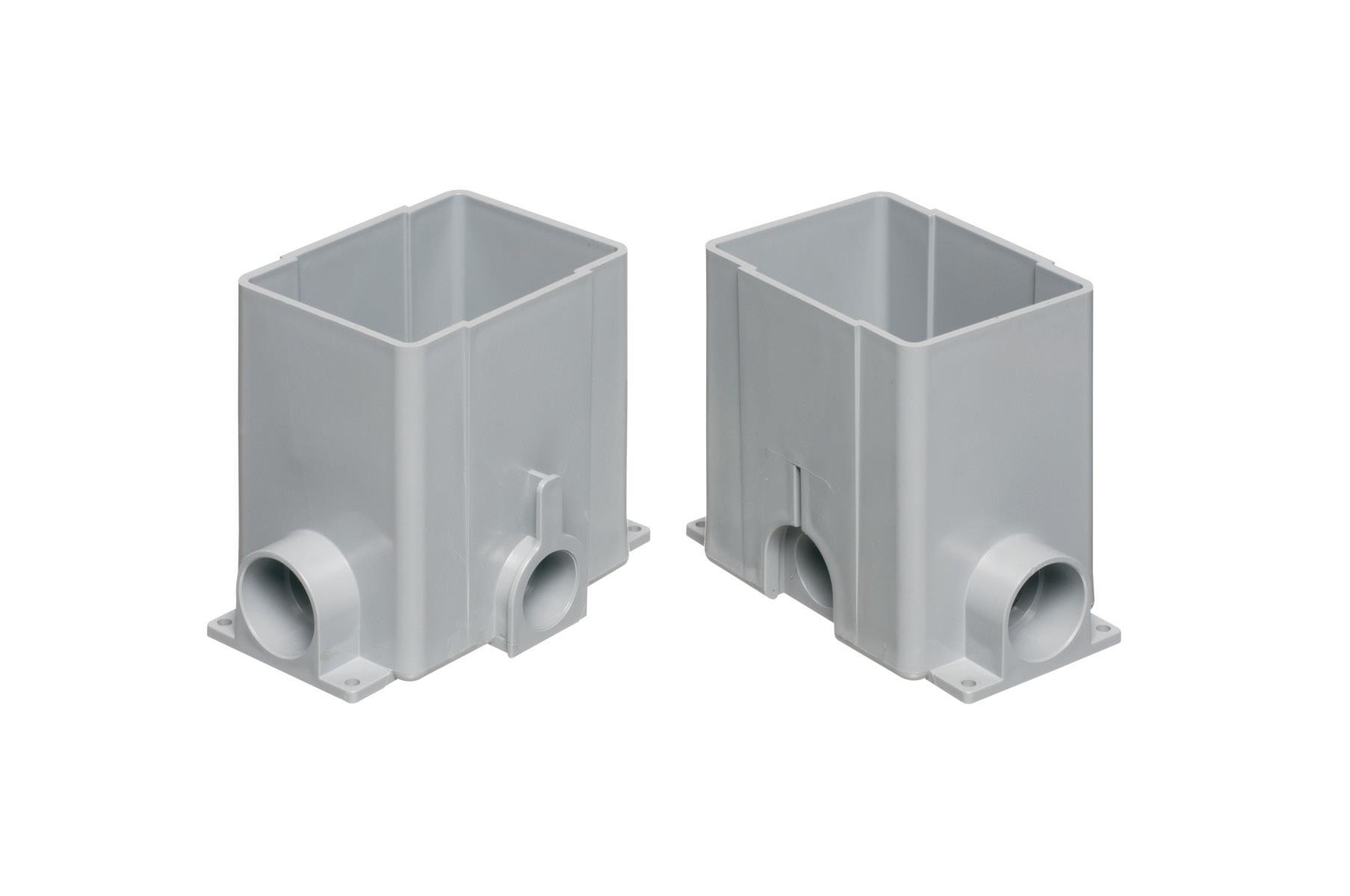
Single gang box
(3) FLBC8500 boxes
(1) FLBC8530BL Black PLASTIC cover/frame kit

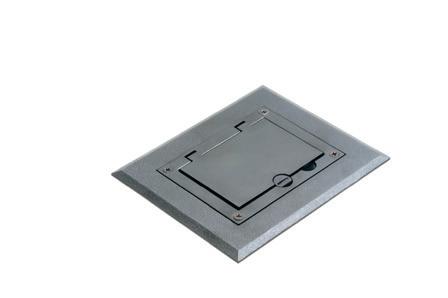
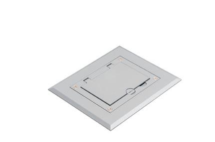
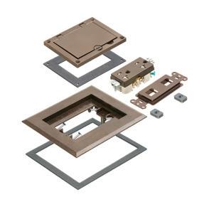

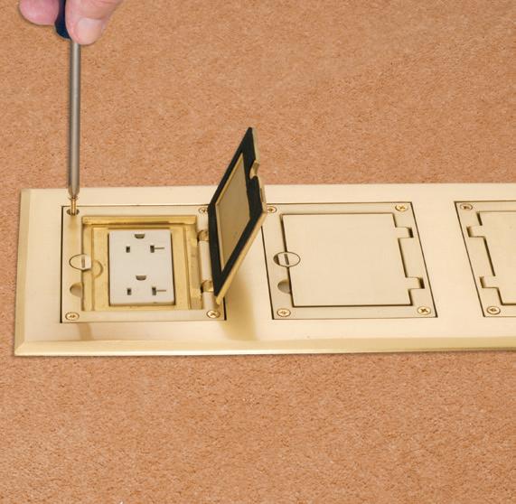


Lock two boxes together for a two-gang box. Add another for three-gang!
Here’s the easy way to add receptacles in a commercial concrete pour. Lock single gangable boxes together to build a two- or three-gang floor box!
Then add the UL LISTED single, two- or three-gang Cover/Frame kit, with devices included.
• PLASTIC in Black, Brown, Gray, Light Almond, Caramel...
• DIECAST ZINC with a Brass or Nickel finish... Furniture feed inserts also available with brass or nickel finish
• PLATED, PLASTIC or POWDER-COATED with Flip Lids
Fast, easy cover installation. Installs with hinge on either side.
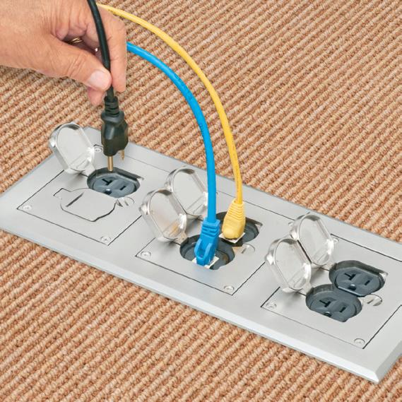

FLBC8500
Schafer. “By nature, they’re intellectual property because it is the way you work. Your workflows are baked into your calculations, so you have to build agents to orchestrate those calculations. I’m actually struggling to think of an idea design-wise that is so straightforward I would want to buy a third-party tool to do it.”
Some of these homegrown tools are chatbots, such as Black & Veatch’s BV Ask.
“We’ve been around for over a hundred years, and those hundred years have baked valuable knowledge into our policies, our processes, our procedures, our lessons learned,” Elbert says. “Our professionals can ask a question and [receive] responses with context and citations and point them right to the policy and procedure that applies, to subject matter experts, and things like that. That’s been a really important use case for us.”
Another example is CannonDesign’s Billie chatbot.
“In 2024, we were experimenting with the major off-the-shelf tools available at the time, but we quickly identified a significant gap between their consumer capabilities and our specific professional needs,” says Joel Yow, director of digital products. “The primary shortcoming wasn’t just that they were general business tools, but that they operated as closed systems with limited access to relevant data. Off-the-shelf models could write a convincing paragraph, but they couldn’t reference our past projects, our specific design standards, or the vast institutional knowledge we’ve built over decades. They were brilliant, but at the time, they were blind to who CannonDesign was.”
Developing AI tools in-house also reduces reliance on vendors that could discontinue products or go out of business completely.
“A significant risk with consumer AI products right now is that many are ‘wrappers’: user interfaces built on top of OpenAI, Google, or Anthropic that serve to replicate key functionality but do not fully understand our business processes,” Yow says. “One of our key vendor selection criteria is, ‘Does this product have proprietary data or
a unique workflow engine that cannot easily be replicated?’ If we feel the product is fundamentally reselling access to frontier models, especially those models being offered by vendors that are not profitable yet, they are high-risk for the AI bubble pop due to pricing changes or slow enterprise adoption. Getting a company of our size hooked on a product or API that a vendor decides is no longer profitable and shuts down is not an option for us.”
This risk is why CannonDesign gave Billie a nimble architecture that was easily extensible.
One key to a great design — whether it’s an ultra-secure AI tool or a LEED Platinum building — is experience, which is where relying on AI can actually be detrimental.
“Right now, it connects to many different models, including OpenAI, and we are responsible for the development of our own modularity and features.” Yow says. “If OpenAI were to disappear tomorrow, or if a better, cheaper model emerges from Google, AWS, or Meta, we can ‘swap the engine’ in the background or update functionality with very little friction or negative impact to our users.”
CYBERSECURITY AND JOB SECURITY
Developing chatbots and other AI tools in-house also helps ensure that proprietary company and client data doesn’t inadvertently wind up in a software vendor’s cloud.
“We focus a lot on ‘secure by design,’” says Heath Jeppson, Stanley Consultants senior cybersecurity analyst and author
of a forthcoming book, AI Exposed: The Naked Truth. “You have to take every possible avenue to harden the system where you can. We even go beyond the NERC Critical Infrastructure Protection (CIP) requirements by designing these systems so they have that robustness that is going to be required in the future.”
One key to a great design — whether it’s an ultra-secure AI tool or a LEED Platinum building — is experience, which is where relying on AI can actually be detrimental.
“In the cybersecurity field itself, there’s a lot of boring grunt work that goes on behind the scenes that most people have no idea about,” Jeppson says. “It’s kind of a double-edged sword because the industry no longer has junior analysts going through logs and looking for patterns. We’re seeing organizations use AI to do that instead. But that experience is what kind of forges you in the cybersecurity world — spending that time in the trenches.”
One thing is clear: AI isn’t going away, and neither are the people who use it.
“I was talking to some college students, and they’re really worried whether there will be jobs for them when they graduate,” Elbert says. “I go back to when I started at Black & Veatch. Computers showed up, and we’re still here. Like computers many years ago, AI is a powerful tool to assist engineers in efficiently producing quality deliverables.”
In other cases, new graduates and experienced professionals alike are looking at a firm’s AI adoption when deciding which job offer to take.
“Employees are demanding that we figure this out,” says Henderson’s Schafer. “Employees don’t want to work at a firm that isn’t using AI because they worry that that’s where the jobs will get lost. They feel like if a firm is doing this, that’s where the job will get retained and added. There’s the adage of ‘You don’t lose your job to AI. You lose your job to a person who’s using AI.’ Everyone wants to be the person using AI.”
Kridel is an independent analyst and freelance writer with experience in covering technology, telecommunications, and more. He can be reached at tim@ timkridel.com.
Making Sense of the K-Shaped Economy
Retail Activity Trend Accelerated in 2025
Advanced Retail Trade and Food Services: U.S. Total — Rates of Change
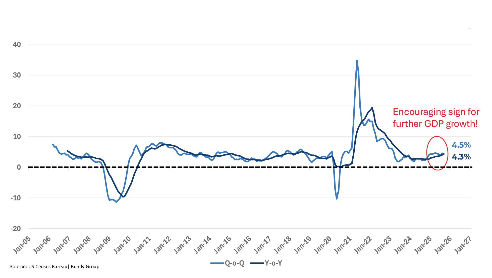
Fig. 1. Consumption remained healthy in 2025, accelerating throughout the year.
What the latest economic data means for the electrical industry as we enter 2026.
TBy Alex Chausovsky, the Bundy Group
he macroeconomic outlook remains mixed as we enter 2026, partly due to the absence of reliable data stemming from the longest government shut down in history and the disconnect between the messages that hard data (like retails sales, industrial production, capital investment, and jobs) and soft data (like consumer and CEO confidence) are sending right now. As we plan for 2026, an objective assessment is necessary to have realistic expectations for the economy and for growth in the electrical industry in the year ahead. Planning for mild, single-digit macroeconomic growth next year appears to be the prudent thing to do. However, an acknowledgement of the fact that we’re traversing a K-shaped economy — with winning and losing sectors — is equally prudent.
RETAIL SALES AND LABOR MARKET TRENDS
Consumption is the main driver of the U.S. economy, with personal consumption expenditures comprising about two-thirds of gross domestic product (GDP) every
Job Gains Weaker Since April (Liberation Day)
U.S. Total Nonfarm Employees — Change, Thousands of persons
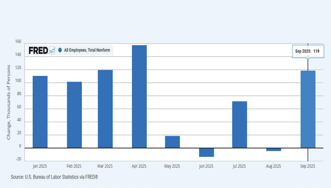
year. An effective way to track consumption, which reflects the consumer’s willingness and ability to spend money, is through a data series called “Advance Retail Sales for Retail Trade and Food Services,” published monthly by the U.S. Census Bureau. As of the third quarter of 2025, this series alone represented more than $8.6 trillion of economic activity on an annualized basis.
Despite all the policy uncertainty and geopolitical turmoil witnessed in 2025, retail sales accelerated over the course of the year and were up 4.3% on a cyclical basis (year-over-year) through September (Fig. 1 on page 47). Initial data for holiday sales, specifically the critical Black Friday through Cyber Monday weekend, is coming in stronger than anticipated. This shows that U.S. consumers, despite feeling gloomy about the economy, kept spending throughout the year, although the bulk of that spending is attributed to high-income earners (more on this later).
The job market rebounded in September, with the U.S. economy adding 119,000 jobs (Fig. 2), bucking the recent trend of weaker job gains since April. Although unemployment ticked up slightly to 4.4%, wages were up 3.8% over the past 12 months, outpacing inflation and helping consumers feel like they can continue to spend money. Unfortunately, revisions to employment data from July and August showed that job gains for the two months were 33,000 lower than previously reported. May and June were also quite weak from a hiring perspective.
Objectively, it’s evident that the labor market is noticeably weaker since April, when “Liberation Day” launched a moreaggressive reciprocal tariff regime against America’s trade partners, and companies adopted a wait-and-see mentality regarding their robust hiring plans.
CONSUMER AND BUSINESS CONFIDENCE
While the latest available “hard” data for retail sales and job gains was somewhat encouraging, “soft” proprietary data that tracks sentiment and reflects how individuals and businesses think, feel, and talk about the economy was more negative in November (as it was not interrupted by the government shutdown), and has been compared to the hard data for many months. In assessing data series
such as U.S. Consumer Confidence and CEO Confidence from the Conference Board, we get a glimpse into the mindset of consumers and businesses, including those in the electrical industry, allowing us to ascertain what their outlook is heading into 2026.
The Consumer Confidence Index (Fig. 3) declined by 6.8 points in November to 88.7, falling to its lowest level since April after moving sideways for several months. The pullback was evident in both the Present Situation Index, which reflects consumers’ assessment of current business and labor market conditions, and the Expectations Index, which portrays consumers’ near-term outlook. Consumers were notably more pessimistic about business conditions six months from now and indicated plans to curb spending, at least to a degree, in the months to come.
The Measure of CEO Confidence (Fig. 4 on page 49) is a barometer of the health of the U.S. economy from the perspective of U.S. chief executives and gauges CEOs’ expectations about future actions their companies plan to take regarding capital spending, employment, recruiting, and wages. The Index, which has declined precipitously since early 2025, fell to 48.0 in Q4, down one point from 49.0 in Q3. A reading below 50 reflects more negative than positive responses. CEOs’ views of general economic conditions now versus six months ago remained slightly negative, while CEO’s six-month expectations for the economy turned from neutral to pessimistic. This points
Weak Consumer Confidence as of Late 2025 Consumer Confidence Index®
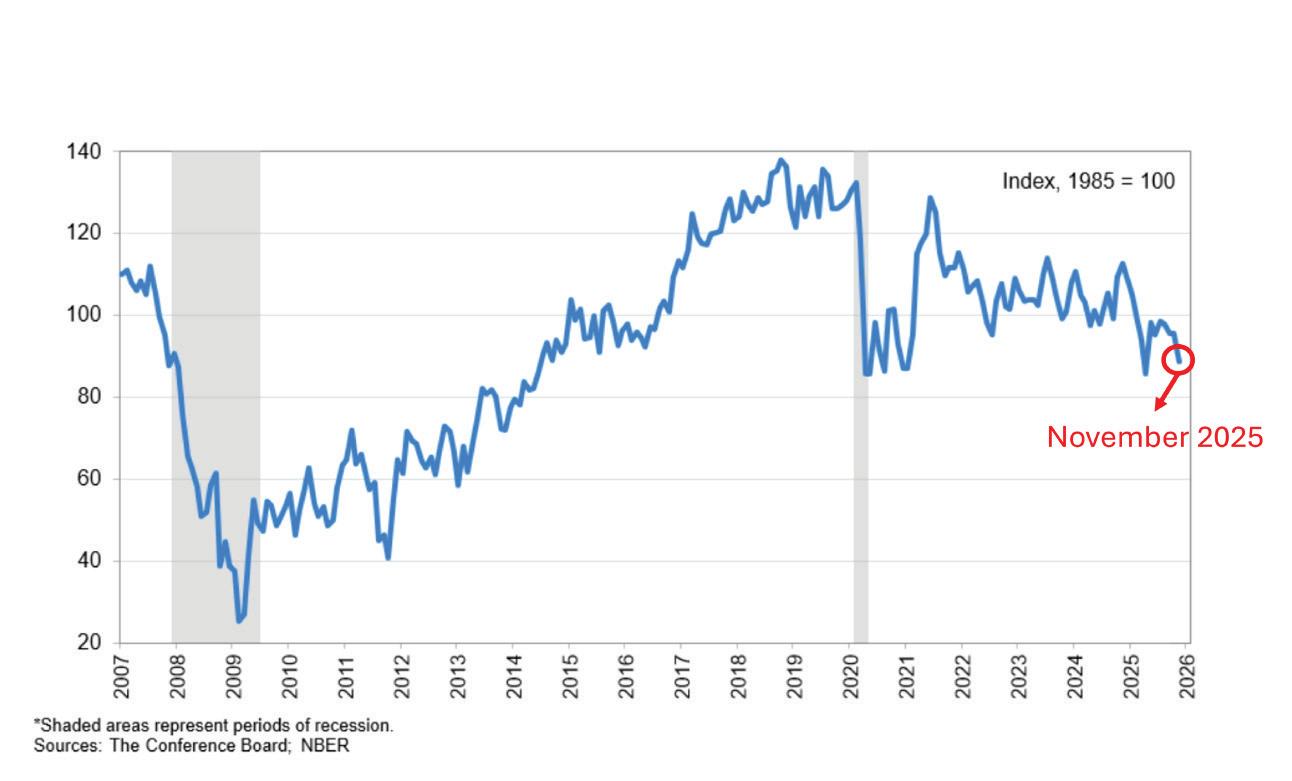
Fig. 3. Consumers are nearly as pessimistic today as they were during COVID.
Fig. 2. April’s tariff announcement stymied hiring activity last year.
to persisting headwinds for the industrial economy and, potentially, for the electrical industry as we enter 2026.
INDUSTRIAL PRODUCTION AND CAPITAL INVESTMENT
U.S. Industrial Production, a benchmark for the volume of industrial activity/ capital spending and a reflection of the B2B economy, is a much better barometer for the electrical industry than consumption or overall job gains. The industrial production business cycle (assessing rates-of-change on a yearover-year basis) closely matches that of the electrical industry, with turns in the cycle and transitions from periods of growth to contraction and vice versa happening on a similar timeline.
A recent annual revision of “U.S. Industrial Production” data from the Federal Reserve Board showed that there has been essentially no growth in the industrial economy over the last two years. In fact, comparing the 12-month moving total values from September 2023 to September 2025 yields growth of -0.002% during this 24-month timespan (Fig. 5). This is a validation of the notable headwinds the electrical sector has faced in recent years. In the last few months, Industrial Production has been slowly accelerating, and currently the shortterm (quarter-over-quarter) growth rate stands at 1.3%, while the longer term (year-over-year) growth rate remains a more-anemic 0.4%. However, the upside momentum in the quarterly rate was broken after April’s “Liberation Day” announcement, and the current trajectory of the series, including the latest input from leading indicators, points to sideways movement as the most likely trajectory over the next two quarters.
Capital spending data, represented by a series called “U.S. Nondefense Capital Goods New Orders,” is performing much better. Through September 2025, annual Capital Goods New Orders were up 2.1%. Furthermore, the quarterly growth rate was 4.1%, implying more upside momentum is imminent for the annual growth rate over the next two quarters (Fig. 6). However, as this series is dollar-denominated, whereas Industrial Production is an index, the acceleration in the New Orders data is at least partially
CEOs Lack Confidence Heading into 2026
CEO Confidence ticked down to further below neutral in Q4
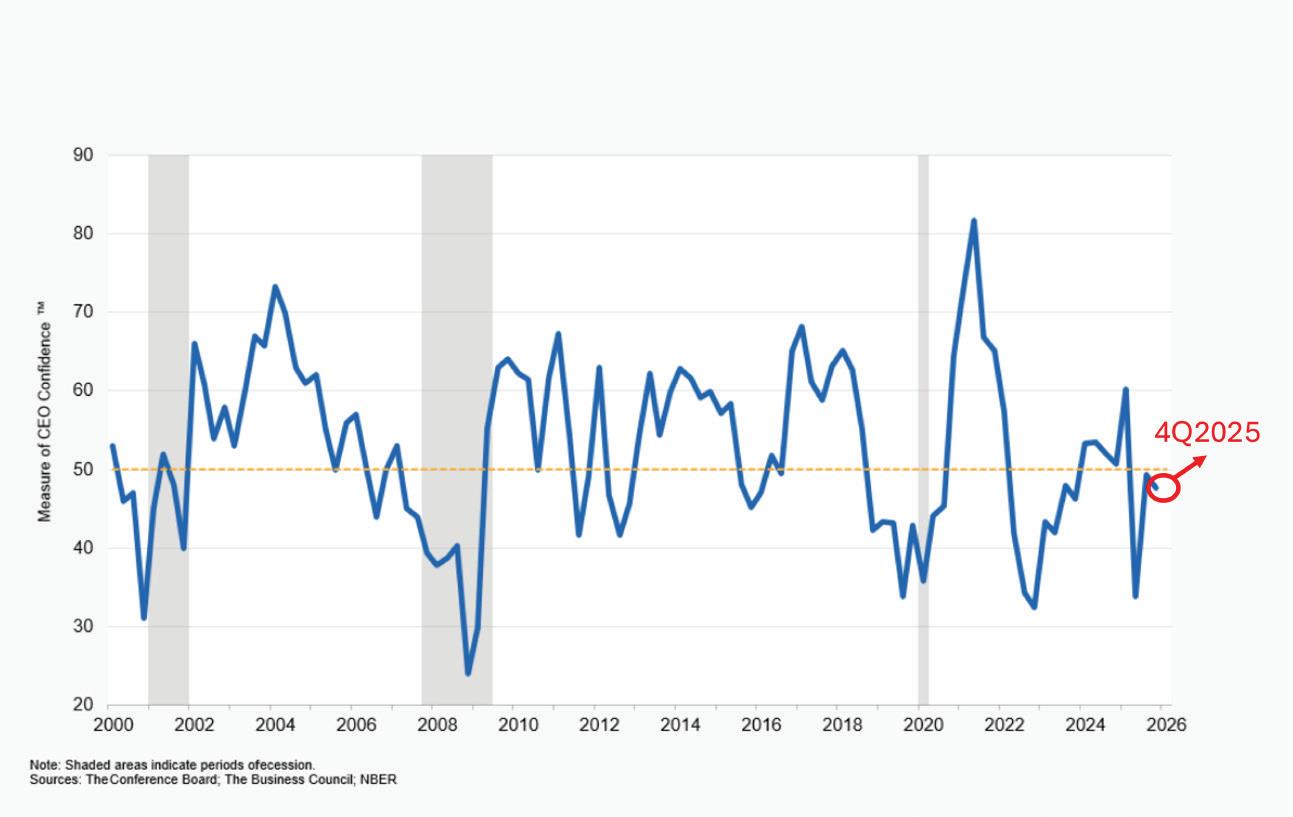
U.S. Industrial Production (B2B Economy) Index — Revised data through September 2025
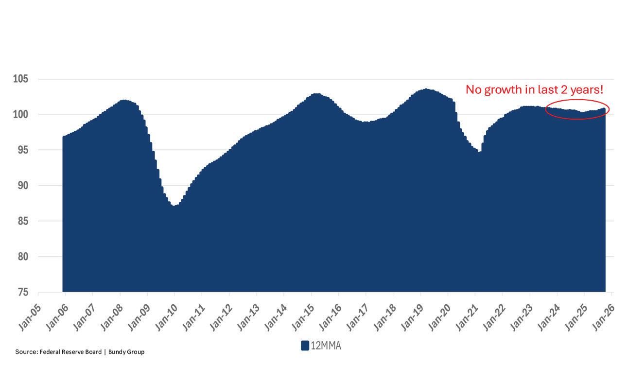
Price Increases Driving New Orders Higher
U.S. Manufacturers’ New Orders Quarterly and Annual Growth Rates (%) Revised data through September 2025
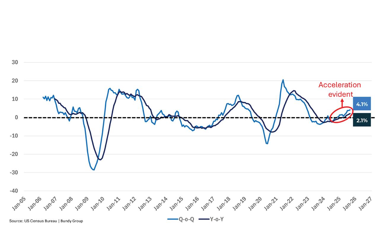
Fig. 4. Lackluster business confidence reflects an uncertain policy landscape.
Fig. 5. The industrial economy has not grown since 2023.
Fig. 6. Acceleration in new orders is mostly driven by price increases.
reflecting the impact of price increases — and not just organic market growth. In other words, the disparity between the growth rates of the two series in Fig. 5 and Fig. 6 on page 49 presents clear evidence of inflationary pressure. Heading into 2026, companies in the electrical industry must focus on profitable revenue growth, as inflation will likely continue to accelerate into 2026.
Companies in the electrical industry must focus on profitable revenue growth, as inflation will likely continue to accelerate into
2026.
THE K-SHAPED ECONOMY
A K-shaped economy describes a bifurcated economic landscape, where different segments of the economy perform at vastly different rates — like the two diverging lines of the letter “K.” In late 2025, examples of a K-shaped economy can be found in both the retail sales-driven consumption sector, which comprises nearly 70% of GDP, and the capital investment-driven construction sector, which is more directly relevant to companies in the electrical industry. Figure 7 shows that while overall Retail sales are growing at a healthy clip through September, it is the top 20% of income earners that are driving growth, while the middle-class and bottom 40% of income earners are just keeping up with inflation. As shown in Fig. 8, the K-shaped economy is also evident as data center construction is up by $16 billion from the start of 2024, while the rest of nonresidential construction is down by more than $55 billion over the same time frame.
The K-shaped economy highlights an unusually complex period for the electrical industry. Macro-economic
The K-Shaped Economy: Consumption
The U.S. economy depends on consumption by the rich Wealthy Americans in the top 20% continue to grow their spending. Meanwhile, the “revenge spending” era for middle-class and lower-income Americans is over. Their spending is roughly in line with inflation. (Chart shows growth in personal outlays vs. inflation.)
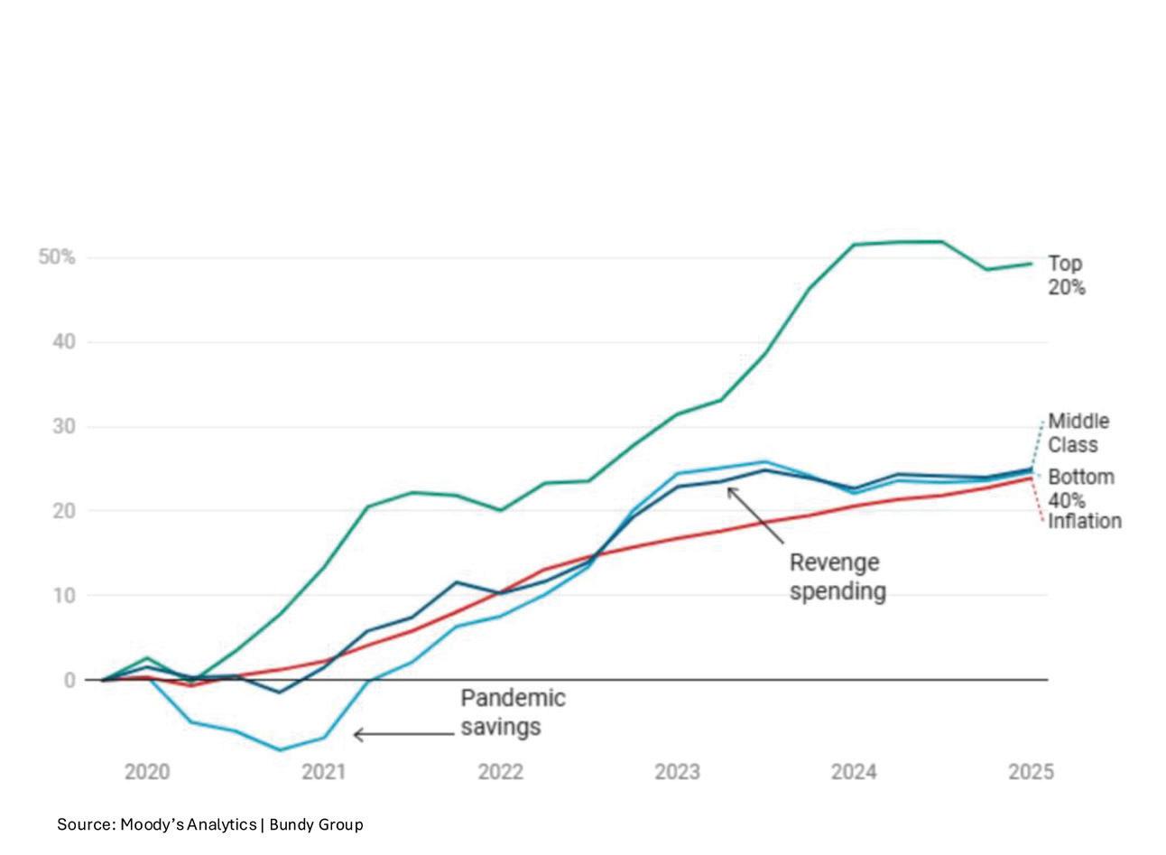
The
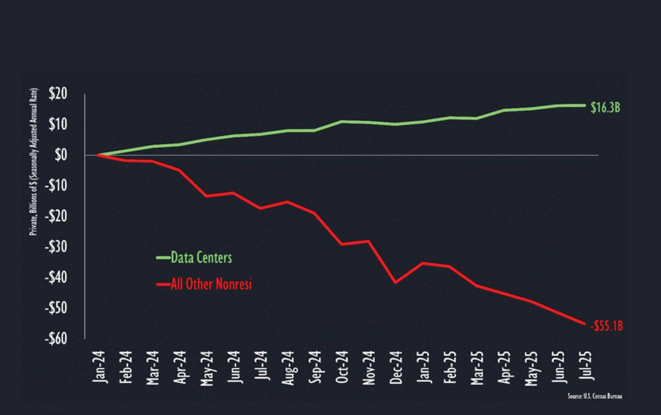
growth appears solid, yet hiring is sluggish, and the unemployment rate has ticked up. Overall, consumer spending is still rising, but Americans are less confident. AI-related data center construction is soaring while nonresidential construction and the housing sector are in recession. This conflicting narrative underscores the need for companies in the electrical industry to remain nimble and to pivot to the outperforming sectors of the market — all while mitigating the downside pressure and risks associated with the
underperforming sectors. A proactive strategic approach — one that requires market share gains and new customer acquisition — is the only certain way to ensure company performance meets targets and objectives in 2026.
Director of Analytics and Consulting at the Bundy Group, Alex is a highly experienced market researcher and analyst with more than two decades of expertise across industries such as automation, industrial technology, health care, business services and manufacturing.
Fig. 7. Top 20% of income earners driving most consumption growth since 2020.
K-Shaped Economy: Construction Change in Private Construction Spending Since Start of 2024
Fig. 8. Data center construction is a bright spot in the nonresidential sector.
Mastering Advanced Bidding Strategies in Electrical Contracting
From document review to post-bid analysis, a playbook for modern electrical estimating success

By Melvin Newman, PataBid
In the competitive world of electrical contracting, knowing how to estimate electrical jobs effectively can make the difference between winning profitable projects and missing out on opportunities. For electrical contractors, mastering advanced estimating methodologies isn’t just about calculating material costs. It’s about developing a comprehensive strategy that positions your electrical business for success.
UNDERSTANDING ESTIMATING FUNDAMENTALS
Before diving into advanced techniques, let’s clarify what electrical construction estimating entails. At its core, electrical construction estimating is the process of predicting the costs, resources, and time required to complete an electrical project. Your estimation method directly impacts your ability to win bids while maintaining healthy profit margins. A robust estimation methodology considers not only materials and labor, but also risk factors, market conditions, and competitive positioning. Modern estimating technologies have revolutionized how electrical contractors approach this critical process, enabling more accurate electrical takeoffs and streamlined bid
Courtesy of PataBid


Safety Matters
This twice-a-month e-newsletter delivers the latest trends and information on electrical safety, reports on specific accidents in the field, and provides tutorials and evergreen safety content that can be used for reference and training.
Topics covered include:
• Best practices for safely working on electrical equipment
• Accidents and investigations
• Arc flash
• PPE
• Shock and electrocution
• Fire and security
• Safety audits
Subscribe Today
See all of our EC&M e-newsletters at www.ecmweb.com
preparation. However, technology is only as effective as the methodology behind it.
ESSENTIAL DRAWING AND DOCUMENT REVIEW METHODS
Comprehensive drawing analysis
The foundation of accurate electrical estimating begins with a meticulous review of drawings. Read all notes on every drawing, and identify any scope that is in addition to the core electrical specifications. This means going beyond the obvious — look for notations in corners, revision clouds, and general notes that might reference additional electrical work not immediately visible in the electrical plans. Many electrical estimators miss scope items hidden in these details, leading to underbidding or costly change-orders later.
Thorough specification review
Your estimating methodology must include a complete review of the electrical specifications. Read all documents, and identify any electrical items that you need to supply, along with the associated labor and costing required. Electrical specifications often contain requirements for testing, commissioning, warranties, and electrical submittals that don’t appear on drawings. Each of these items carries both material and labor costs that must be captured in your estimate. According to industry research, careful consideration of all electrical project costs — both direct construction costs and indirect construction costs that support project completion — is essential for better project performance. This comprehensive approach ensures nothing falls through the cracks.
Addendum management and version control
One of the most common estimating errors is working from outdated information. Check to see if there are any addenda, and make sure to load them into your electrical drawing package. Make notes to ensure you’re using the correct drawing, as there might be multiple copies of the same electrical drawing. Always use the most current version of each drawing. Create a systematic approach: Maintain a master log of all drawing revisions and addenda, mark superseded electrical drawings
clearly, and cross-reference your electrical takeoff to ensure you’re working from current documents.
STRATEGIC BIDDING POSITIONING
Proactive general contractor engagement
Understanding how to estimate electrical jobs also means understanding the bidding landscape. Reach out to the project architect or representative and find out which general contractors are planning to bid on the project. Once you have that list, reach out to the GCs and introduce yourself. Ask to be added to their bidding list. Don’t limit yourself by only bidding to one GC. This approach serves multiple purposes: It expands your opportunities, provides leverage in negotiations, and significantly increases your chances of securing work.
Competitive intelligence through supplier relationships
Your electrical suppliers can be valuable sources of market intelligence. When you submit your electrical bill of materials (BOMs) to your suppliers, ask them how many other electrical contractors are bidding on the RFQ. This information helps you gauge competition levels and adjust your strategy accordingly. Suppliers often know which electrical contractors are actively pursuing projects and can provide insights into electrical pricing trends.
Strategic risk and effort analysis for bids
Not every project deserves equal pursuit. Complete a risk/effort analysis for the project. If you find out that many electrical contractors are chasing the same project, determine if you have an edge that will make you competitive. It may be in your best interest to just move on to the next project opportunity. Consider factors such as your relationship with the GC, your experience with similar projects, your current workload capacity, and whether you have unique capabilities that give you an advantage. Sometimes the smartest electrical bid is the one you don’t submit, allowing you to focus resources on opportunities with better win probability. Using software to create a risk registry, which quantifies risks, can be an effective way to determine which jobs to target.
MANAGING DISCREPANCIES AND SCOPE CLARIFICATION
Drawing conflicts are inevitable when working on complex electrical projects. As you read through electrical drawings, you will notice discrepancies. If it is something small, make a note within your quote letter — upon award, this could be your first change notice. If it is something larger, it will probably be best to pose it as a request for information (RFI). This will force the engineer to clarify the situation. It should also ensure that all electrical contractors bidding on the project are estimating the same scope of work. This estimation method protects you from electrical scope gaps while ensuring competitive equity. Document everything: Take screenshots of electrical conflicts, note sheet and detail numbers, and maintain a clarification log.
MAINTAIN BIDDING PIPELINE CONSISTENCY
Understanding electrical construction estimating includes recognizing that estimating is not a feast-or-famine activity. You always need to be bidding, or your work activity will start to feel like a roller coaster. Constantly bidding will keep the electrical work flowing. Develop a disciplined approach: Allocate specific time each week to electrical estimating regardless of current workload, maintain a pipeline of electrical opportunities at various stages, and track bid dates in a calendar system. Successful electrical contractors treat estimating as a core business function — not something done only when work slows down.
POST-BID WORK AND MARKET INTELLIGENCE
Your electrical estimation method shouldn’t end when you submit a proposal. Follow up on every electrical bid with every GC. This will tell you how your bid compares to your competition. If you are constantly high, you need to reduce either your electrical labor rate or your markup. With this information, you’ll also start to see who the more successful GCs are — if they’re getting the work, you want to be bidding to them. Create a tracking system that records your bid amount, competitors’ pricing (when available), winning contractor, and final award amounts. This data is
invaluable for calibrating your estimates through post-project analysis — where you can evaluate the cost components that deviated from the estimate and why. This continuous improvement cycle is essential for long-term success.
LEVERAGING SUPPLIER RELATIONSHIPS
Material costs often represent the larg est component of estimates. If you have a substantial material list, you can ask your supplier to provide a package price for the material. It doesn’t hurt to ask for a buydown on the material when work ing with package deals. This is a good way to reduce your price and possibly gain an edge over your competitors.
INTEGRATING METHODS FOR ESTIMATING EXCELLENCE
Mastering how to estimate jobs requires more than technical takeoff skills. It demands a comprehensive project estimation methodology that encompasses thorough document review, strategic bidding positioning, intelligent risk assessment, and continuous market intelligence gathering.

EV Infrastructure
Electrical contractors who consistently win profitable work aren’t necessarily the ones with the lowest labor rates. They’re the ones who have developed systematic, repeatable estimating methodologies that minimize errors, maximize strategic positioning, and leverage every available advantage in the competitive bidding environment. By implementing these advanced techniques into your daily estimation practice, you’ll improve your win rate and ensure the electrical projects you do win are properly scoped, competitively priced, and positioned for profitability from day one.
Melvin Newman is the visionary force behind PataBid. As President/CTO, he’s not just a seasoned pro with 15+ years in construction estimating — he’s also a trailblazing entrepreneur. Melvin cofounded PataBid in 2018, revolutionizing the industry through cutting-edge software and digital tools. From estimator and Contech guru to a dynamic full stack developer, Melvin brings unparalleled expertise in AI, ML, systems development and their intersection with the construction industry.
This twice-a-month e-newsletter tracks the development, design, installation, and safe operation of electric vehicle supply equipment and systems.
Topics covered include:
• Applying NEC requirements
• Industry news and trends
• New products
• Federal investment allocation
• National EV charging infrastructure buildout development
Subscribe Today
See all of our EC&M e-newsletters at www.ecmweb.com
Understanding Organizational Changes to the 2026 NEC
Key changes to the latest edition of the National Electrical Code, including structure, definitions, additions, deletions, and reorganization
By Randy Barnett, Electrical Specialist
The National Electrical Code (NEC) has undergone a major reorganization of content for the 2026 edition. Reorganizing information into applicable topic areas improves usability and effectiveness, thus reducing user frustration.
Electrical workers have long welcomed
change within the industry. Electronic tablets, electric conduit benders, laser levels, digital multimeters, non-contact voltage detectors, and cordless band saws are just a few of the examples of productivity tools that were not available in 1937 — the last time the NEC was reorganized. Improvements to the most important tool we have for building compliant and
safe installations (the NEC) were needed and result in a commonsense improvement to the document.
CHANGING THE STRUCTURE
Using the 2026 NEC requires familiarity with a new Code structure. Section 90.3 addresses the overall arrangement of content (Fig. 1 on page 54). Chapters 5 through 8 have been retitled to more correctly address their content. Chapter 8 is no longer standalone. Two Articles in this chapter have been deleted, and it now only addresses communications systems and wiring outside and entering a building. Once inside the building, the communication wiring requirements are now found in new Chapter 7 Articles on Limited-Energy Systems. The content of Art. 805 [Communication Circuits] has been moved to Chapter 7 and Art. 840 [Premises-Powered Broadband Communication Systems] has been deleted.
Informative Annexes provide supplemental information for Code users. Two Annexes have been deleted. Annex E [Types of Construction] and Annex J [ADA Standards for Accessible Design] no longer exist.
Of special interest is the new Informative Annex L, which provides the proposed organization for the 2029 National Electrical Code. This future edition is proposed to have more than 20 chapters! Understanding the 2026 reorganization and the grouping of various topics into the many new Articles should make perfect sense for 2029. Usability will be even more improved with this next edition. Informative Annex L provides topics by Chapter and Article, then gives the location of the material in the 2023 NEC, the 2026 NEC, and the proposed 2029 NEC. This makes for easy comparison and becomes beneficial for Code users attempting to find the new location of certain topics within the 2026 edition.
REORGANIZATION OF ARTICLES BY TOPIC
Modern data center construction is an excellent example of how technology has forced Code structure changes. Consider the installation of the entire electrical system in a large, campus-style data center. Medium-voltage switchgear is installed at the service for incoming electric utility power. Large mediumvoltage generators are installed for required power reliability. Voltages are transformed to utilization voltages for 480V, 208V, and 120V systems. Feeders, branch circuits, and equipment must all be installed to distribute this power. Then at the heart of the data center is the myriads of low-voltage copper and optical fiber communication wiring.
The major differences in the construction and installation techniques for these systems account for much of the Code reorganization for 2026. Systems greater than 1,000VAC or 1,500VDC require certain knowledge and skills for installation. Medium- and high-voltage cables are required to be installed by specially trained and qualified personnel. Impedance grounding is installed for these systems. Overcurrent protection is accomplished using current transformers and protective relays.
The communication system wiring installed is powered from limited-energy sources. A new “Limited-Energy System” definition explains that these systems either limit the current and voltage levels to much safer values than the
Generalization of Titles for New Articles for Systems and Equipment
Rated Over 1,000VAC, 1,500VDC, Nominal
Article 245 for Overcurrent Protection
Article 265 for Branch Circuits
Article 266 for Feeders
Article 267 for Outside Branch Circuits and Feeders
Article 268 for Services
Article 270 for Grounding and Bonding
Fig. 2. New Articles have been added to Chapter 2 [Wiring and Protection]. Previous Arts. 305, 315, and 495 covering these systems and equipment have been left in place. Often referred to in the field as medium- or high-voltage systems, the NEC has not yet defined these terms.
Generalization of Titles for New Limited-Energy (L-E) System Articles
Article 720 for General Requirements for L-E Wiring Methods and Materials
Article 721 for Power Sources
Article 272 for L-E Cables (Includes Optical Fiber)
Article 723 for Raceways, Cable Routing Assemblies, and Cable Trays
Article 742 for Overvoltage Protection
Article 270 for Grounding and Bonding
Fig. 3. Two Articles from the previous edition in Chapter 8 [Communication Systems] have been deleted and information incorporated into Chapter 7 Articles on limited-energy. Article 770 [Optical Fiber Cable] has also been deleted, with information placed into these new limited-energy Articles.
remaining distribution system or quickly deenergize the source. Code requirements will thus be less restrictive than for those systems that can injure personnel or create fire hazards. Communication cable trays, Cat-rated Ethernet cable, and optical fiber cable are examples of wiring and systems that must be installed.
Much of the 2026 NEC reorganization simplifies the location of the various installation requirements.
• The medium-voltage systems have been logically grouped into new Articles in Chapter 2 [Wiring and Protection]. Article 305 [General Requirements for Wiring Methods and Materials for Systems Rated Over 1,000VAC, 1,500VDC, Nominal and Article 315 Medium Voltage Conductors, Cable, Cable Joints,
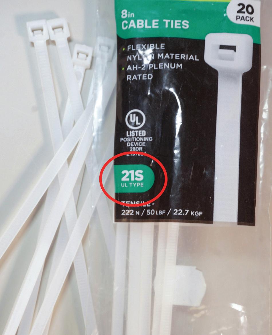
Fig. 4. Section 300.13(E) [Cable Ties Used as Means of Securement and Support] requires cable ties used to secure and support cable, flexible conduit, and flexible tubing be listed and identified for securement and support. The new Art. 100 definition “Cable Tie” provides an informational note indicating the “21S UL Type” has been evaluated for these securement and support purposes. The new definition clarifies that these cable ties would comply with this requirement.
and Cable Terminations] remain in their current location in Chapter 3 [Wiring Methods and Materials], as seen in Fig. 2 on page 55). Limited-energy systems, including communication wiring, are now in Chapter 7 [Specific Conditions and Systems]. The previous Art. 770 [Optical Fiber Cables] has been deleted and its information relocated into the new Limited-Energy System Articles (Fig. 3 on page 55).
• Chapter 1 [General] now includes two Articles relocated from elsewhere in the Code. Article 220 from Chapter 2 is now Art. 120 [Branch-Circuit, Feeder, and Service Load Calculations]. Article 750 is now Art. 130 [Energy Management Systems].
• For the commonly installed electrical equipment, little has changed. There has been no reorganization on topics such as transformers, motors, panelboards, fuses, and circuit breakers, and the sizing of conductors and raceways; only the typical technical content changes associated with any new Code edition have taken place.
GLOBAL IMPROVEMENTS
Readability has been improved by revising some lengthy paragraphs into lists of items. Expanded use of acronyms eases online searches when accessing the NEC through NFPA Link. New definitions and acronyms help add clarity for interpretation and enforcement.
There have also been changes for identifying revised material. Some specific Sections within each Article are now standardized as to content. See the sidebar on “Navigating the Changes to the 2026 National Electrical Code” below for help in identifying these global changes and navigating the 2026 NEC.
NEW DEFINITIONS AND ARTICLES
Proper terminology is always key to interpreting Code rules. New definitions and revisions to some existing terms help to
Navigating Changes to the 2026 National Electrical Code
When navigating the NEC, understand the methods NFPA uses to denote changes. Also refer to nfpa.org for current Tentative Interim Amendment (TIA) and Errata information.
These specific Sections are now formatted the same for all Articles:
• XXX.2 Listing Requirements
• XXX.3 Reconditioned Equipment
Revision symbols used in the 2026 NEC:
• Colored (Shaded) Text = revised text
• D D before Section = words with the Section have been deleted
• D to the left of a table or figure number = revised table or text
• D entire Chapter marked throughout = Chapter heavily revised
• · = one or more Sections deleted. Bullet symbol appears between deleted Sections.
• N = new Chapter, text, Section, table, figure
• T = Tentative Interim Amendment (TIA) revision
• M = Section has moved from another location
provide clarity. Examples of new Art. 100 definitions include:
• Cable Tie, and Cable Tie Fixing Device provide clarity for components used in many installation applications (Fig. 4 on page 56).
• Conductive Pavement Heating System definition applies to installations in Art. 426 [Fixed Outdoor Electric Deicing and Snow-Melting Equipment].
• Electric Self-Propelled Vehicle (ESV), Electric Self-Propelled Vehicle Supply Equipment (ESVSE), and Electric Self-Propelled Vehicle Power Export Equipment (ESVPE) all apply to the new Art. 624 addressing nonautomotive type electric vehicles.
The definition for Special Purpose Ground-Fault Circuit Interrupter (SPGFCI) has been expanded to individually define the specific classes based on their purpose.
For example, all SPGFCIs are for circuits where no conductor exceeds 300V to ground. A Class C SPGFCI can be used where reliable equipment grounding or double insulation is provided. A Class D SPGFCI is installed with specially sized grounding so that the voltage across the body during a fault does not exceed 150V. A Class E SPGFCI is designed to rapidly open the faulted circuit before current flow through the body would cause ventricular fibrillation.
Some terms we often use in the field are now defined in Art. 100:
• Line-to-ground
• Line-to-line
• Line-to-neutral
• Generator terminals
• Transformer secondary conductors
A new Art. 206 [Non-Power-Limited Remote-Control and Signaling Circuits] addresses typical lighting and motor control circuits (Fig. 5). Remote-control is provided by start and stop pushbuttons located at some distance from the motor. Green and red lamps are generally used to indicate motor operation. The power supply for these circuits is not limited to safe values.
Article 624 [Electric Self-Propelled Vehicle Power Transfer Systems (ESVSEs)] covers the installation and wiring of the charging systems for electric vehicles that are not automotivetype, such as electric-driven forklifts.
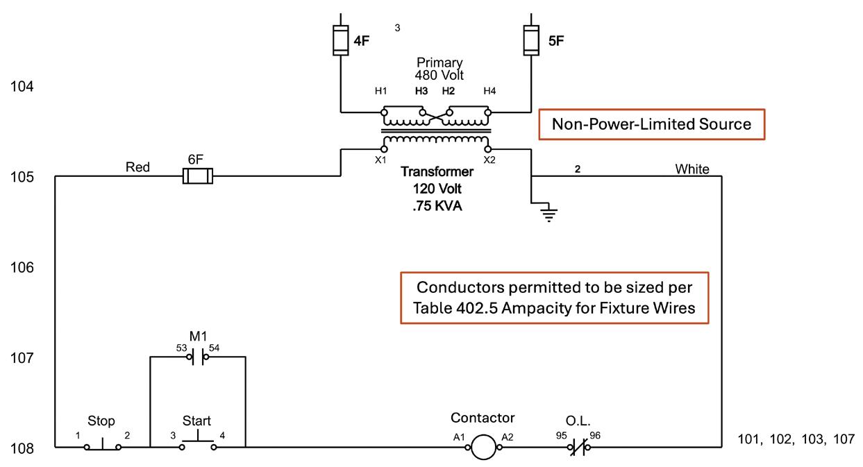
Fig. 5. This new Article separates the general requirements for circuits often used for motor or lighting control into their own Article. A non-power-limited source provides power to a contactor, which is remotely energized to close contacts and energize the load.
STUDY THE RULE CHANGES.
Individual rule changes are numerous. For example, Sec. 110.14 [Electrical Connections] changes the term “suitable” to “identified.” Sec. 250.64 [Grounding Electrode Conductor Installation] now gives provisions for splicing the grounding electrode conductor. Section 300.4 [Limitations] has a new requirement to replace damaged wiring (Fig. 6). Section 314.16(B) [Box Fill Calculations] now specifies that splicing connectors (e.g., twist-on, push-in connectors) are not to be included in box fill calculations. Snap switches have been moved from Art. 404 [Switches] to Art. 406 [Wiring Devices] because they are a wiring device. Looking for information in the wrong place creates confusion and frustration.
Reviewing the many changes takes a large amount of time and effort. Code users should identify the major changes of interest, then consider more in-depth research and training on topics that affect their work.
SUMMARY
The 2026 NEC is the first major step in reorganizing Code material into topics that identify how we install electrical systems. It is much easier to stay within one area within the Code to locate information than referencing back and forth between Chapters and Articles. New Articles for “Systems Rated Over 1,000VAC, 1,500VDC, Nominal” have been grouped in

Fig. 6. Damaged wiring is now addressed in Sec. 300.4(C) [Damaged Conductors and Wiring Methods]. Overheating, fire, corrosion, and moisture can all damage wiring, which then must be evaluated and replaced if required.
Chapter 2. Limited-Energy Systems information has been grouped into new Articles in Chapter 7. Chapter 8 is now Communications Systems — Outside and Entering Buildings. New and revised definitions provide clarity. As is true with any new Code edition, many technical content changes require individual study. Electrical workers, inspectors, and other Code users will find improved usability with this new edition. Review the layout of the 2026 NEC, and study the individual changes to ensure compliance and a safe built environment.
Randy Barnett is a Master Electrician and Certified Electrical Safety Compliance Professional. He can be reached at www.randybarnett.net.
PRODUCT NEWS
Work Boot
The Second Shift waterproof steel-toe work boot is a rugged work boot designed for job-site durability and safety. It features a steel toe that protects against impact and compression. In addition, the boot offers electrical hazard protection in accordance with ASTM standards. A full waterproof membrane and waterproof full grain leather keeps feet dry in wet conditions. The boot includes a slip-resistant, industrial-grade rubber outsole for traction on slick or uneven surfaces, and Goodyear welt construction that provides maximum durability for the product.
Cat Footwear
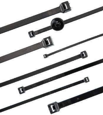
Cable Ties

Post-industrial recycled nylon 6.6 cable ties are created with up to 100% post-industrial recycled nylon. The latest addition to the company’s cable tie lineup helps manufacturing organizations meet their sustainability goals by reducing their carbon footprint through the use of recycled material content in these cable tie products. The cable ties provide long-lasting performance, making them an effective alternative to standard plastic cable ties, according to the company. They are impact-modified, heat-stabilized, and UV resistant to support outdoor or indoor installations.
Panduit
Power Distribution Block
The company has expanded its line of TOPJOB S power distribution terminal blocks with a new 4-gauge input. The product has a 0.5-in. compact design that significantly reduces its footprint on the DIN rail. The 2216 and 2016 Series are all UL-1059 certified and rated for 70A/600V applications. Other benefits include a built-in meter lead test port for touch-safe troubleshooting, moulded conductor entry markings for easy identification, and compatibility with 2004 series TOPJOB S push-in jumper bars for scalable connectivity.
WAGO

Beam Laser Measure
S50 green-beam laser measure is a laser distance meter designed for job sites, renovations, and challenging conditions. It uses a bright green-beam laser for improved visibility — even outdoors — and supports measurements up to 400 ft with ±1/16 in. precision up to 400 ft. The device offers up to eight measurements per second and multiple measurement modes, including distance, area, volume, and point-to-point (P2P).
A 2.4-in. IPS display and multiple reference-point options (front, back, tripod, side-laser alignment) make it flexible for different jobs. Powered by rechargeable batteries (or USB-C), it features a durable, dust- and water-resistant housing suitable for professional use.
MILESEEY
Circuit Tracer
The SureTrace Pro circuit tracer provides an accurate breaker, conductor, and fault-finding solution for energized/de-energized electrical systems, including 3-phase. The transmitter is equipped with auto continuity tester, voltage measurement (24VAC to 600VAC and 12VDC to 600VDC), DC polarity, and receptacle testing features. Measure amperage (0 to 600A AC) with the inductive sensing clamp and/or use the clamp to induce a tracing signal on conductors when access to termination points is not possible. Users can trace circuits and locate breakers in all positions and low-light conditions using the integrated work light.
IDEAL Electrical

Safety Eyewear
Spike safety eyewear combines anti-fog technology, UV protection, and adjustable features. Its BK-Anti-Fog+ layer is fused into the lens during manufacturing to provide long-term fog resistance and meet EN 166/168 performance standards. According to the company, the product is equipped with UV 6 protection that blocks 99.99% of UVA and UVB rays. The design includes five-step angle-adjustable temples, a floating rubber nosepiece, an integrated brow guard, and flexible temple tips to support a customized fit. The rimless style offers a lightweight option for workers seeking comfort and consistent eye protection.
Brass Knuckle

Circular Saw
Pliers Set

The TwinGrip pliers set is a versatile tool kit featuring front- and side-gripping jaws to handle screws, bolts, or fasteners (even stripped or worn) across a size range of 1/8 in. to 11/16 in. According to the company, the slim-head design and narrow turning profile make it effective in confined spaces. The jaws are forged from chrome-vanadium steel, oil-hardened for durability, and hardened to approximately 61 HRC for strong grip. The product has a box-joint construction, serrated gripping surfaces, and a pinch guard add safety and long-term reliability. Finally, the adjustable slip-joint positions (three for the 6 in., five for the 8 in., and seven for the 10 in.) allow flexible gripping capacities for different tasks.
KNIPEX Tools
The 20V MAX XR 7¼-in. metal cutting circular saw is designed for tough applications, delivering up to 1,400 MWO of power while maintaining a lightweight design for easier handling. This tool can complete a variety of applications with a 2⅝-in. depth of cut and features an integrated chip collector to help maintain a clean work area. The product is built for productivity across a variety of metal-cutting tasks, and the saw is part of the company’s 20V MAX* XR lineup. Maximum initial battery voltage (measured without a workload) is 20 and 60. Nominal voltage is 18 and 54, respectively.
DEWALT
Leather Pouch
Heated Hoodie

The M12 heated hoodie uses the company’s Hexon Heat Technology to provide adjustable warmth for job-site and outdoor use. The garment features two heat zones in the chest and back with high, medium, and low settings, offering up to 8 hr of runtime on low, 4 hr on medium, and 2 hr on high. A battery pass-through pocket allows the power source to be positioned in the front or back. The hoodie is made from a cotton/polyester fleece blend with a jersey lining, a three-panel hood, full-zip front, and three pockets.
Milwaukee Tool
The heavy-duty 8-pocket leather pouch is a rugged, top-grain leather tool pouch designed for efficient job-site use. It features a large divided main pocket and four smaller compartments to keep tools organized and accessible. Washer-reinforced rivets, a heavy-duty tape-measure holder, a tape chain, and an extra-large metal tool clip add durability and convenience. The pouch fits tool belts up to 3 in. wide and offers tapered pockets for secure tool stability — designed for electricians, maintenance, or general trade work.
Greenlee

NEC Requirements for Outside Circuits
Circuits installed outside are more vulnerable than those installed inside; therefore they have special requirements.
By Mike Holt, NEC Consultant
Article 225 contains requirements for outside branch circuits and feeders not over 1,000VAC or 1,500VDC, installed on or between buildings, structures, or poles (Fig. 1).
Conductors installed outdoors can serve many purposes, such as lighting and power for outdoor equipment or providing power to separate buildings. For overhead spans up to 50 ft long, you can use conductors 10 AWG and larger. For spans over 50 ft, the minimum size conductor is 8 AWG, unless supported by a messenger wire [Sec. 225.6(A)(1)]. The reason for these size requirements is the need for adequate mechanical strength to support the weight of the conductors and to withstand wind, ice, and other similar conditions.
Overhead conductors for “festoon lighting” cannot be smaller than 12 AWG and must be supported by messenger wire (with strain insulators) whenever the spans exceed 40 ft long [Sec. 225.6(A)(B)].
The point of attachment for overhead conductors to buildings must be at least 10 ft above the finished grade. You may need to raise the point of attachment so the overhead conductors will comply with the clearances from building openings and other building areas required by Sec. 225.19 [Sec. 225.16(A)]. It’s wise to look for an alternate route that avoids these conflicts.
Open conductors must be attached to buildings by fittings identified for use with conductors or to noncombustible, nonabsorbent insulators securely attached to the building [Sec. 225.16(B)].
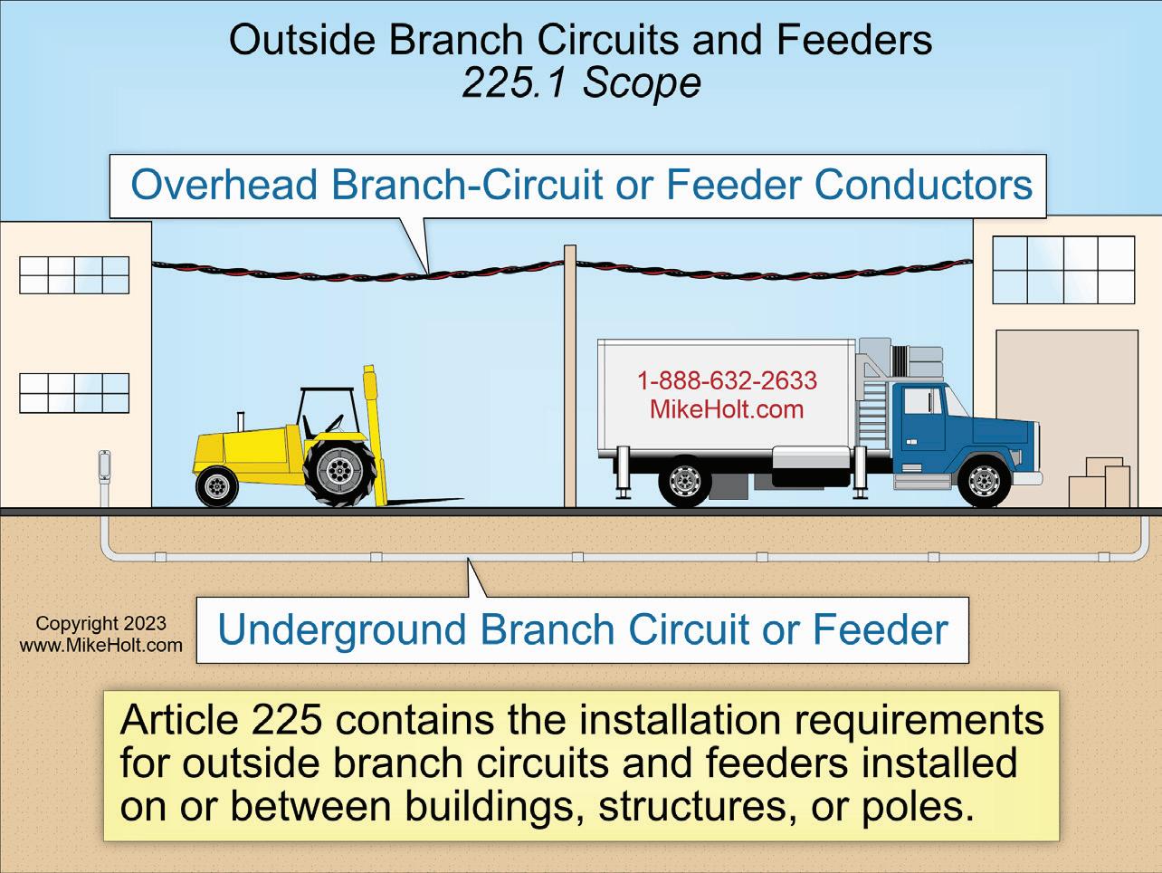
Fig. 1. Article 225 contains requirements for outside branch circuits and feeders not over 1000VAC or 1500VDC, installed on or between buildings, structures, or poles.
SUPPORTS
Any mast for the support of overhead conductors must have adequate strength, braces, or guy wires to safely withstand the strain caused by the overhead conductors [Sec. 225.17(A)]. Overhead conductors cannot be attached to a mast between a weatherhead and a coupling located above the last point of securement or where the coupling is above the roof [Sec. 225.17(B)].
You cannot use vegetation to support overhead conductor spans [Sec. 225.26,].
CLEARANCE FOR OVERHEAD CONDUCTORS
Overhead conductor spans must
maintain clearances as outlined in Sec. 225.18. For example, they must be 18 ft over public streets, alleys, roads, parking areas subject to truck traffic, driveways on other than residential property, and other areas traversed by vehicles such as those used for cultivation, grazing, forestry, and orchards. They must also maintain vertical and horizontal clearances from buildings as outlined in Sec. 225.19. For example:
• Vertical clearance of 8 ft, 6 in. above the surface of a roof for at least 3 ft from the edge of the roof.
• Clearance of at least 3 ft from signs, chimneys, radio and television antennas, tanks, and other nonbuilding
structures; and from windows that open, doors, porches, balconies, ladders, stairs, fire escapes, or similar locations.
RACEWAYS
Raceways on exteriors of buildings must be arranged to drain and be listed or approved for use in wet locations [Sec. 225.22]. Where an outside raceway enters a building, it must be sealed with a sealant that is identified for use with the conductor insulation [Sec. 225.27], as shown in Fig. 2.
WHEN FEEDERS SUPPLY BUILDINGS
A building can be supplied by only one feeder, except as permitted in Sec. 225.30(A) through (F). For example, you can use additional feeders to supply fire pumps and emergency systems. Other examples are when you have different voltages, frequencies, or uses, such as controlling outside lighting from multiple locations.
DISCONNECTING MEANS
A disconnect is required for all feeders that supply, enter, or pass through a building [Sec. 225.31(A)].
Install the feeder supplied disconnect at a readily accessible location, either outside or inside the building nearest the point of entrance of the conductors [Sec. 225.31(B)]. Feeder conductors under at least 2 in. of concrete or encased in at least 2 in. of concrete are considered outside a building in accordance with Sec. 230.6.
The building feeder disconnecting means can consist of no more than six switches or six circuit breakers in a single enclosure or in separate enclosures grouped together [Sec. 225.33(A)].
The building feeder disconnecting means must be grouped in one location and marked to indicate the loads they serve [Sec. 225.34(A)].
To minimize the possibility of accidental interruption of critical power systems, the disconnect for a fire pump, emergency systems, legally required standby systems, or optional standby systems must be installed remotely from the normal power disconnect [Sec. 225.34(B)].
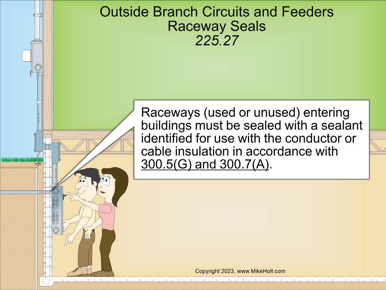
IDENTIFY MULTIPLE SUPPLIES
If a building is fed by more than one feeder or service, a permanent plaque or directory must be installed at each feeder disconnect location denoting all other feeders and services supplying that building and the area served by each [Sec. 225.37].
This information is critically important to first responders who almost certainly will not be familiar with the electrical distribution system of the facility but will need to disconnect power to the building during an emergency.
The feeder disconnect must meet minimum ampere ratings per Sec. 225.39(A) through (D).
• Single branch circuit: 15A
• Two 2-wire branch circuits: 30A
• One-family dwelling: 100A
• Other installations: 60A
EMERGENCY DISCONNECTS
For one- and two-family dwellings, an emergency disconnect must be installed at a readily accessible outdoor location on or “within sight” of the dwelling unit [Sec. 225.41(A)(1)]. The emergency disconnect must have a short-circuit current rating equal to or greater than the available fault current [Sec. 225.41(A)(2)]. If more than
one emergency disconnect is provided at a building, they must be grouped [Sec. 225.41(A)(3)].
Where disconnects for other energy source systems are not adjacent to the emergency disconnect, a plaque or directory identifying the location of other energy source disconnects must be adjacent to the emergency disconnect [Sec. 225.41(B)]. See Secs. 445.18, 480.7, 705.20, and 706.15 for examples of other energy source system disconnecting means.
The emergency disconnect must be marked “EMERGENCY DISCONNECT“ [Sec. 225.41(C)]. Markings must be permanently affixed and be sufficiently durable to withstand the environment involved per Sec. 110.21(B). The emergency disconnect marking or label must be on the outside front of the disconnect with a red background and white text, and the letters must be at least 1/2 in. high.
SURGE PROTECTION
Where any of the following occupancies are supplied by an outside feeder, a surge protective device (SPD) is required [Sec. 225.42(A)]:
• Dwelling units (Fig. 3 on page 62)
• Dormitory units
Fig. 2. Where an outside raceway enters a building, it must be sealed with a sealant that is identified for use with the conductor insulation.
CODE BASICS

CodeWatch
This e-newsletter, published four times per month, is dedicated to coverage of the National Electrical Code. The content items are developed by well-known Code experts.
CodeWatch promises to:
• Explain how to properly apply the Code
• Test your knowledge of the Code
• Provide information on upcoming Code-related seminars and shows
• Offer Code quizzes and real-world Code violations
Subscribe Today
See all of our EC&M e-newsletters at www.ecmweb.com
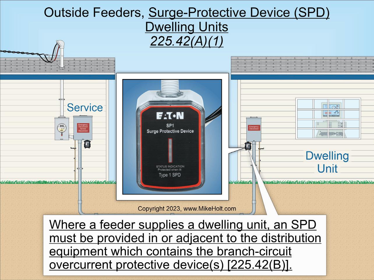
• Guest rooms and guest suites of hotels and motels
• Areas of nursing homes and limited-care facilities used exclusively as patient sleeping rooms.
The feeder SPD must be either Type 1 or Type 2 [Sec. 225.42(C)] and have a nominal discharge current rating (In) of at least 10kA [Sec. 225.42(E)].
Where feeder supplied distribution equipment is replaced, an SPD is required for the distribution equipment [Sec. 225.42(D)].
Install it in (or adjacent to) feeder distribution equipment [Sec. 225.42(B)]. Surges can be generated from lightning, the electric utility, or utilization equipment. Surge protection is most effective when installed closest to the branch circuit(s) with lead lengths of conductors to the SPD kept as short and straight as is practical. See Parts I and II of Art. 242 for installation requirements that apply to SPDs.
PRO TIP
To ensure an outside conductor installation is both Code compliant and completed efficiently, actively look for alternatives to your original plans before sending them out to the field. This takes
time and some thinking, but the payoff can be big.
For example, it looks like you save money on conductors in your bill of materials by using the most direct and obvious path when routing. But if that path takes you over a balcony or through some trees when you could instead go around them, you will have a more complex installation that carries higher material costs, longer installation time, and higher risk of a Code violation — and probably higher maintenance costs.
Using a different path, you could reduce the complexity and thus the total installation cost and the total lifetime cost — even if it’s longer and uses more materials. Maybe going around the east side of the building instead of the west side would eliminate half a dozen clearance concerns.
Map out the location of every connection point, and then decide the conductor routing between those points based on what is actually there. Consider what is above, below, and adjacent to the proposed routing.
These materials are provided by Mike Holt Enterprises in Leesburg, Fla. To view Code training materials offered by this company, visit www.mikeholt.com/code.
Fig. 3. Per Sec. 225.42(A), a surge protective device (SPD) is required for dwelling units supplied by an outside feeder.
CODE QUIZ OF THE MONTH
Test Your Code IQ
How much do you know about the National Electrical Code?
By Mike Holt, NEC Consultant
All questions and answers are based on the 2023 NEC.

Q1: Receptacles shall not be installed inside the tub or shower or within a zone measured 3 ft horizontally from any outside edge of the bathtub or shower stall. Receptacles installed where a hydromassage bathtub is _____ with the supply receptacle accessible only through a service access opening shall be permitted.
a) rated 20A or less
b) rated 30A or less
c) six or more
d) less than 125V
Q2: The minimum ampacity of conductors feeding a group of welders shall be based on the individual currents determined in Sec. 630.11(A) as the sum of _____ of the two largest welders, plus 85% of the third largest welder, plus 70% of the fourth largest welder, plus 60% of all remaining welders.
a) 100% c) 150%
b) 125% d) 175%
Q3: A circuit breaker with a _____ rating, such as 120V/240V or 480Y/277V can be used on a solidly grounded circuit where the nominal voltage of any conductor to ground does not exceed the lower of the two values, and the nominal voltage between any two conductors does not exceed the higher value.
a) straight
b) slash
c) high
d) low
Q4: Where the opening to an outlet, junction, or switch point is less than 8 in. in any dimension, the length of free conductor of each conductor, spliced or unspliced, shall extend at least _____ outside the opening of the enclosure.
a) 1 in.
b) 3 in.
c) 6 in.
d) 12 in.
Q5: Metal underground systems or structures such as piping systems, underground tanks, and underground metal well casings that are not bonded to a metal _____ are permitted as grounding electrodes.
a) gas pipe
b) fire-sprinkler pipe
c) water pipe
d) none of these
Q6: Type NM cable on a wall of an unfinished basement installed in a listed raceway shall have a _____ installed at the point where the cable enters the raceway.
a) suitable insulating bushing or adapter
b) sealing fitting
c) bonding bushing
d) junction box
See the answers to these Code questions online at ecmweb.com/55340095.
CODE VIOLATIONS
Illustrated Catastrophes
By Russ LeBlanc, NEC Consultant
All references are based on the 2023 edition of the NEC.
POOL CHEMICALS CAUSING PROBLEMS
I think this photo shows us a great example of how badly electrical equipment can be damaged by corrosive pool chemicals. The aluminum box is corroding into a bluish-white powder, and the galvanized metal conduits are rusting away. This is typical of what can happen to certain metals when exposed to strong oxidizing agents like chlorine.
For general installations, Sec. 300.6 requires raceways, boxes, fittings, supports, support hardware, and other equipment and components to be made of materials suitable for the environment in which they are to be installed. For installations in corrosive environments at swimming pools, Sec. 680.14(A) provides a short list of permitted wiring methods: RMC, IMC, PVC conduit, RTRC (fiberglass conduit), and LFNM conduit. For other equipment, such as boxes and enclosures, Sec. 680.14(B) requires them to be suitable for use in corrosive environments or be installed in identified corrosion-resistant enclosures. Equipment specifically listed for pool and spa use is also permitted for this use. While RMC is permitted here, perhaps stainless-steel or PVC-coated RMC might have held up better against the corrosion. Also, while Sec. 680.14 does not specifically prohibit installing aluminum boxes here, installing aluminum conduit and aluminum
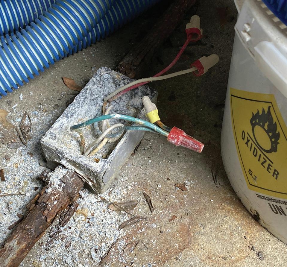
tubing is prohibited. A stainless-steel box or nonmetallic box may have been a better choice here.
SAD WIRING ON THIS SIGN
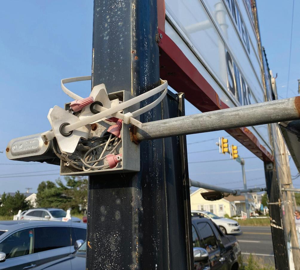
I’m not sure what those cable ties are for, but I think they were used to attach a banner to this signpost. In any case, spotting those giant cable ties is what drew me over to this installation, where I discovered the cover missing off of the box installed here. Section 314.15 requires completed box installations to have a cover, faceplate, lampholder, or luminaire canopy installed to cover the box and protect the wiring and splices. These wires and splices are exposed to sun, rain, ice, and whatever else Mother Nature can throw at them. The wire connectors have faded and are becoming dried and brittle from being exposed to the elements. The same can be said about the conductors. The missing cover and damaged wires/wire connectors can increase the chances of people getting shocked since this equipment is fully accessible to the general public. Another problem here is lack of support for the RMC and boxes for the luminaires. The supporting of the RMC does not comply with Sec. 344.30. The boxes installed in the RMC for mounting of the luminaires do not comply with any of the box supporting requirements found in Sec. 314.23(A) through (H).
ADVERTISER INDEX
To place a display ad (1/6 page or larger), call the Advertising Sales Representative for your area.
Vice President
Mike Hellmann
Andover, MA • (978) 289-0098
E-mail: mhellmann@endeavorb2b.com
Western U.S. & Western Canada
Ellyn Fishman | Key Account Manager (949) 239-6030
Email: efishman@endeavorb2b.com
Northeast U.S. & Eastern Canada
David Sevin | Account Manager 24 Houghton Street • Barrington, RI 02806 (401) 246-1903
E-mail: dsevin@endeavorb2b.com
Midwest, Southeast,and Southwest
Jay Thompson | Account Manager 7450 W. 130th Street, Suite #210
Overland Park, KS 66213 • (913) 967-7543
E-mail: jthompson@endeavorb2b.com
Marketplace/Inside Sales
Steve Suarez | Media Account Exec 7450 W. 130th Street, Suite #210 Overland Park, KS 66213 • (816) 588-7372
E-mail: ssuarez@endeavorb2b.com


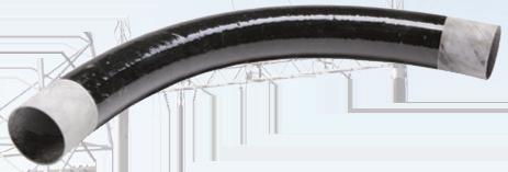


CODE VIOLATIONS
By Russ LeBlanc, NEC Consultant
How well do you know the Code? Think you can spot violations the original installer either ignored or couldn’t identify? Here’s your chance to moonlight as an electrical inspector and second-guess someone else’s work from the safety of your living room or office. Can you identify the specific Code violation(s) in this photo? Note: Submitted comments must include specific references from the 2023 NEC.
Hint: A fire alarm circuit fiasco.
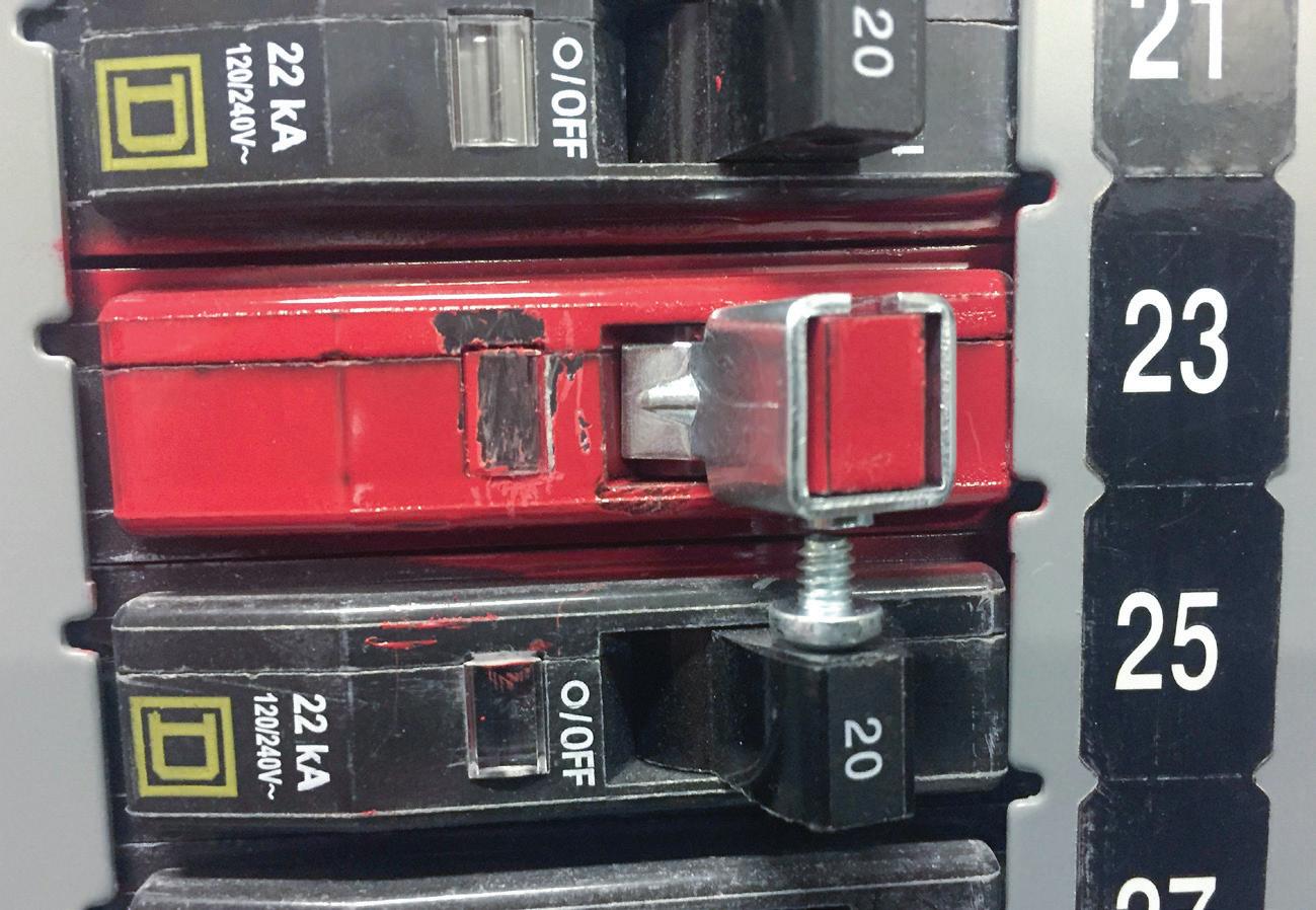
‘TELL THEM WHAT THEY’VE WON...’
”: Using the 2023 NEC, correctly identify the Code violation(s) in this month’s photo — in 200 words or less — and you could win a 40-oz. insulated tumbler valued at $39.99, courtesy of ABB. E-mail your response, including your name and mailing address, to russ@russleblanc.net, and Russ will select two winners (excluding manufacturers and prior winners) at random from the correct submissions. Note that submissions without an address will not be eligible to win.
NOVEMBER WINNER
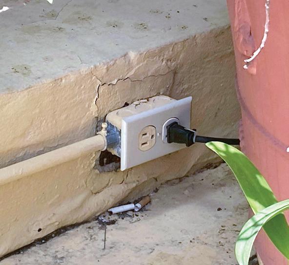
Our winner this month is Pete Paone, senior electrical engineer for NDI Engineering in Thorofare, N.J. He correctly cited several Code violations, including Sec. 406.9(B)(1), which requires a weatherproof enclosure for receptacles rated 15A or 20A, 125V or 250V installed in wet locations. The enclosure must be weatherproof whether anything is plugged into the receptacles. The enclosure in the photo is definitely not weatherproof.
That same Code Section also requires the receptacle to be listed and identified as a weather-resistant (WR) type of receptacle. This duplex receptacle is not a WR type. Lastly, the set screw type of EMT connector is not suitable for use in this wet location and does not comply with Sec. 358.42 or Sec. 314.15, which requires boxes, conduit bodies, outlet box hoods, and fittings installed in wet locations to be listed for use in wet locations.


WHERE FACILITY CHALLENGES FIND SOLUTIONS
CENTRAL VALLEY
March 18-19, 2026
Lodi, CA


SOUTHERN CALIFORNIA
April 8-9, 2026
Anaheim, CA
NORTHWEST
April 29-30, 2026
Portland, OR


UTILITIES PROJECT SOLUTIONS FROM CHAMPION FIBERGLASS®
No burn-through eliminates elbow repairs
Lower material and installation costs
Mechanical strength protects conductors
Low coefficient of friction for smooth pulls
Height adjustable utility risers for easy installation
Operable in temperatures of -40° to +230°F