51 West End Avenue - Design Presentation


Bedroom 2-1 1


GENERAL
THE FOLLOWING SPECIFICATION MUST BE READ IN CONJUNCTION WITH ALL ARCHITECTURAL GENERAL ARRANGEMENT DRAWINGS, SCHEDULES ETC. AND IS APPLICABLE WHETHER SPECIFICALLY REFERRED TO OR NOT. IT IS THE RESPONSIBILITY OF THE CONTRACTOR/SUB-CONTRACTOR TO ENSURE THAT ALL THEIR WORK IS IN COMPLIANCE WITH THE APPROPRIATE REQUIREMENTS OF THE RELEVANT BUILDING REGULATIONS, NHBC STANDARDS AND OTHER ALLIED LEGISLATION.
ALL MATERIALS ARE TO BE USED AND INSTALLED IN ACCORDANCE WITH THE RELEVANT MANUFACTURER'S INSTRUCTIONS AND RECOMMENDATIONS. ALL NEW SERVICES ARE TO BE PROVIDED IN ACCORDANCE WITH THE STATUTORY UNDERTAKER'S REQUIREMENTS. THE QUALITY OF ANY MATERIAL SHALL NOT BE LOWER THAN THAT DEFINED IN THE RELEVANT BRITISH STANDARD, OR THAT THE MATERIAL HAS BEEN SATISFACTORILY ASSESSED BY AN APPROPRIATE INDEPENDENT AUTHORITY I.E. BBA, BRE.
THE CONTRACTOR/SUB-CONTRACTOR MUST ENSURE THAT MATERIALS ARE 'FULLY SUITABLE' FOR THEIR LOCATION AND THAT ALLIED MATERIALS/BACKGROUNDS ARE APPROPRIATE. WHERE THERE IS NO LEGISLATED STANDARD, THE QUALITY AND USE OF THE PRODUCT SHALL BE IN ACCORDANCE WITH ESTABLISHED SATISFACTORY CUSTOMS AND PRACTICES. ALL WORK SHALL BE CARRIED OUT IN A SOUND, NEAT, DURABLE AND WORKMANLIKE MANNER. REASONABLE PRECAUTIONS SHALL BE TAKEN TO PROTECT FIXED AND UNFIXED MATERIALS AGAINST ANY DAMAGE LIKELY TO AFFECT THE FINISHED QUALITY OF THE BUILDING.
ALL CONTRACTORS/SUB-CONTRACTORS MUST ENSURE TO THEIR OWN SATISFACTION THAT THEY ARE IN POSSESSION OF THE CURRENTLY ISSUED DRAWINGS AND DETAILS, BEFORE COMMENCING THE RELEVANT 'WORK-STAGE' ON SITE.
NOTE: UNLESS STATED ALL CONSTRUCTION DETAILS ARE TO BE IN ACCORDANCE WITH THE ROBUST DETAILS DOCUMENT - LIMITING THERMAL BRIDGING AND AIR LEAKAGE PUBLISHED BY DTLR.
THE PRINCIPLE CONTRACTOR IS TO ENSURE THAT THE PROVISIONS OF THE CONSTRUCTION DESIGN MANAGEMENT (CDM) REGULATIONS ARE CARRIED OUT FULLY, INCLUDING ALL NOTIFICATIONS OF WORK REQUIRED UNDER LEGISLATION, PRIOR TO START OF WORKS.
FOUNDATIONS
THE EXISTING GROUND WITHIN THE EXTENT OF THE PROPOSED BUILDING CONSTRUCTION SITE SHALL BE CLEARED OF ALL TURF AND VEGETABLE MATTER PRIOR TO ANY FURTHER EXCAVATION BEING MADE. METHOD OF DISPOSAL OF ANY CONTAMINATED SOIL TO BE AGREED WITH THE LOCAL ENVIRONMENTAL OFFICER. FOUNDATION TRENCHES SHALL BE CLEAN AND TRUE AND CHECKED FOR SOFT AREAS, WATER ETC. AND LEFT WITH COMPACTED BOTTOMS.
FOUNDATIONS SHALL BE LOCATED CENTRALLY UNDER EXTERNAL AND LOAD BEARING INTERNAL WALLS UNLESS IS IT INDICATED IN ARCHITECTURAL DRAWINGS. ALL FOUNDATIONS SHALL BE DESIGNED WITH DUE REGARD TO SUBSOIL CONDITIONS, WATER TABLE, PRESENCE OF SULPHATES AND PREVIOUS GROUND USES ETC. DEPTH OF THE FOUNDATIONS TO SUIT SOIL CONDITIONS, ORIGINAL AND PROPOSED GROUND LEVELS, DRAINAGE TRENCHES AND PROXIMITY OF TREES/HEDGES, ALL TO THE SATISFACTION OF THE RELEVANT BUILDING CONTROL AUTHORITY/NHBC INSPECTOR. READY MIXED CONCRETE WILL ONLY BE ACCEPTABLE FROM SUPPLIERS USING A FULL QUALITY CONTROL SYSTEM.
ENTIRE FOUNDATION DESIGN TO BE IN-ACCORDANCE WITH STRUCTURAL ENGINEERS DESIGN DRAWINGS AND CALCULATIONS.
CONTRACTOR / SUB-CONTRACTOR TO MAKE SURE THERE IS NO ENCROACHMENTS ON SITE.
BELOW GROUND DRAINAGE
ALL DRAINAGE WORKS SHALL BE IN FULL ACCORDANCE WITH APPROVED DOCUMENT H OF THE BUILDING REGULATIONS, BS 8301 AND TO THE COMPLETE SATISFACTION OF THE RELEVANT BUILDING CONTROL BODY.
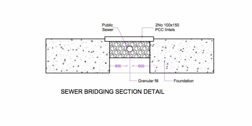
WHERE DRAINS PASS THROUGH EXTERNAL WALLS THEY ARE TO BE PROTECTED WITH A PRE-STRESSED CONCRETE LINTEL OVER (AS DESIGNED BY ENGINEER) WITH MIN. 150MM END BEARINGS, WITH 150MM CLEARANCE ALL ROUND PIPE AND THE OPENING IS TO BE MASKED WITH RIGID SHEET MATERIAL TO PREVENT THE INGRESS OF VERMIN OR FILL.
IF APPLICABLE, REFER TO DRAINAGE ENGINEER'S DETAILED DRAWINGS FOR DRAINAGE LAYOUT AND SPECIFICATION DETAILS.
GROUND FLOOR CONSTRUCTION AS INDICATED IN ARCHITECTURAL GENERAL ARRANGEMENT DRAWINGS AND TO BE CONFIRMED BY ENGINEER.
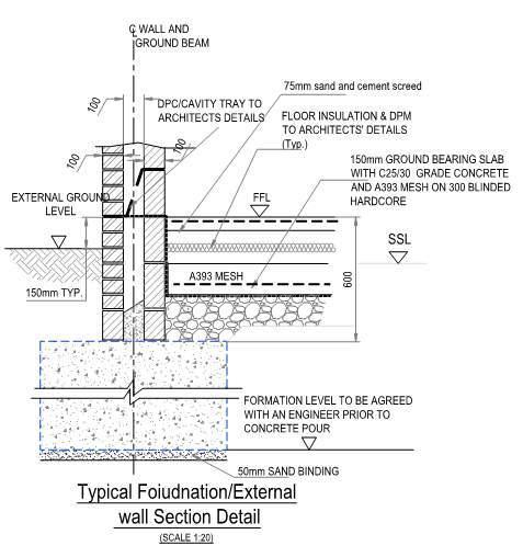
GROUND BEARING FLOOR 75MM REINFORCED SAND/CEMENT SCREED (UNDER FLOOR HEATING TO SPECIALIST'S DESIGN - TO BE CONFIRMED BY THE END USE) ON 1200G POLYTHENE PROTECTION LAYER ON 100MM GA4000 CELOTEX INSULATION (FF4000 FOR UNDER FLOOR HEATING) OR SIMILAR APPROVED ON 1200G DPM ON 150MM CONCRETE GROUND BEARING FLOOR SLAB WITH A393 MESH REINFORCEMENT WITH MIN. 50MM COVER, (ENGINEER TO CONFIRM), ON BRICK BALLAST/CRUSHED STONE BASE ON WELL COMPACTED SOIL 25MM CELOTEX INSULATION STRIP TO BE PROVIDED TO ALL PERIMETER WALLS. CONSTRUCTION TO ACHIEVE U-VALUE OF 0.16
PLEASE NOTE FOR EXTENSIONS ANY EXISTING FLOOR VENTS TO BE CONNECTED WITH 4" PIPE AND VENTED TO EXTERNAL LEAF.
SUSPENDED BEAM AND BLOCK FLOOR : IF REQUIRED 75MM REINFORCED SAND/CEMENT SCREED (UNDER FLOOR HEATING TO SPECIALIST'S DESIGNTO BE CONFIRMED BY THE END USE) ON 1200G POLYTHENE PROTECTION LAYER ON 100MM GA4000 CELOTEX INSULATION (FF4000 FOR UNDER FLOOR HEATING) OR SIMILAR APPROVED ON 1200G DPM ON 150MM BEAM AND BLOCK SUSPENDED FLOOR (ENGINEER TO CONFIRM), WITH MINIMUM 225MM VOID BELOW. 25MM CELOTEX INSULATION STRIP TO BE PROVIDED TO ALL PERIMETER WALLS. CONSTRUCTION TO ACHIEVE U-VALUE OF 0.16
REDUCED LEVEL BENEATH FLOOR SLAB, TO BE TREATED WITH 'APPROVED' WEED KILLER, PRIOR TO INSTALLATION OF FLOOR BEAMS. UNDER FLOOR VOID TO BE CROSS VENTILATED WITH 225X75 AIR BRICK TO BS 493 AT MAXIMUM 2000 CENTRES AND MAXIMUM 450 FROM EXTERNAL/PALARTY WALLS.
FLOOR BEAMS TO BE POSITIONED TO ENSURE THAT BEAMS DO NOT BEAR DIRECTLY OVER 'UNDERFLOOR' VOID VENTILATORS. CAVITY TRAY DPC'S TO BE INSTALLED WHERE EXTERNAL WALL CAVITY IS BRIDGED.
PRE-CAST CONCRETE FLOOR BEAMS TO BE BBA APPROVED ('BISON' OR SIMILAR APPROVED). MINIMUM 450MM FROM UNDERSIDE OF BEAM & BLOCK / CONCRETE FLOOR TO TOP OF FOUNDATION. CONSTRUCTION TO BE CONFIRMED AND DETALED BY STRUCTURAL ENGINEERS ENGINEER.
DAMP PROOF COURSE
HORIZONTAL DAMP PROOF COURSE TO BE MINIMUM 150MM ABOVE ADJACENT GROUND LEVEL. A SECONDARY DPC WILL BE PROVIDED 150MM ABOVE FLOOR LEVEL FOR MINIMUM DISTANCE OF 1.5M FROM ALL EXTERNAL DOORS WITH A LEVEL THRESHOLD. DPC/ CAVITY TRAY TO BE MARLEY AQUAGARD OR SIMILAR APPROVED AND IS TO BE INSTALLED STRICTLY IN ACCORDANCE WITH THE MANUFACTURERS INSTRUCTIONS AND RECOMMENDATIONS.
IF THE EXTERNAL GROUND LEVEL IS EQUAL OR ABOVE THE INTERNAL FINISH FLOOR LEVEL, THEN DOUBLE DPC TO BE PROVIDED, ONE AT FINISHED FLOOR LEVEL AND THE SECONDARY 150MM ABOVE EXTERNAL GROUND LEVEL. BOTH HORIZONTAL DPC'S TO BE CONNECTED WITH AND VERTICAL LAYER OF DPC ALL IN ACCORDANCE WITH ARCHITECTURAL DESIGN AND DETAILS.
CAVITY CLOSURE TO ALL WINDOWS AND DOORS TO REPLACE ALL VERTICAL DPC'S AND IN ORDER TO AVOID COLD BRIDGING.
THE HORIZONTAL DAMP PROOF COURSE SHALL CONSIST OF A LAYER OF 2000 GAUGE POLYTHENE DAMP COURSE TO BS 743/6515 ADEQUATELY LAPPED AT CORNERS AND JOINTS AND LAID ON A MORTAR BED.
WHERE EXTERNAL WALL CAVITY IS BRIDGED I.E. AIR BRICK/VENTILATOR OPENINGS AND METER CUPBOARD ETC. PROVIDE POLYTHENE CAVITY TRAYS COMPLETE WITH STOP ENDS OVER IN THE EXTERNAL WALL WITH OPEN PROPRIETARY PERPENDS. CAVITY TRAYS ARE TO PROJECT 150MM BEYOND EITHER SIDE OF LINTEL/OPENING.
AT ALL ROOF ABUTMENTS I.E PORCHES, GARDEN ROOMS ENSURE STEPPED D.P.C'S CAVITY TRAY WITH STOP ENDS ARE PROVIDED AND LINKED TO CODE 4 LEAD FLASHINGS AND SOAKERS. CODE 4 LEAD DRESSED BENEATH CAVITY TRAYS AND OVER ROOF SLOPES WITH ALTERNATE PERPENDS LEFT OPEN FOR WEEPHOLES ALL AS NECESSARY TO FORM WEATHER PROOF JUNCTION. ALL LEADWORK TO SOAKERS, FLASHINGS, VALLEYS ETC. ARE TO BE IN COMPLIANCE WITH THE RECOMMENDATIONS OF THE LATEST EDITION OF THE LEAD SHEET ASSOCIATION'S 'GUIDE TO GOOD PRACTICE'.
REFER TO FLOOR PLANS AND STRUCTURAL ENGINEERS DETAILS FOR RECOMMENDED LOCATION OF MOVEMENT JOINTS TO OUTER LEAF BRICKWORK/BLOCKWORK, GENERALLY TO BE PROVIDED AT NOT GREATER THAN 6 METRE CENTRES FOR BLOCKWORK AND 12-15 METRE CENTRES FOR BRICKWORK. MOVEMENT JOINTS TO BE 10MM MINIMUM WIDE, LOCATED BEHIND RAIN WATER DOWN PIPES WHERE POSSIBLE AND FORMED WITH PROPRIETARY POLYURETHANE SEALING STRIP, WITH FLAT TIES BETWEEN PANELS AT 450MM VERTICAL CENTRES WITH ONE END DE-BONDED WITH POLY-SULPHIDE SEALANT TO EXTERNAL FACE OF BRICKWORK - COLOUR TO MATCH. NOTE : PROVIDE CAVITY WALL TIES WITHIN 150MM HORIZONTALLY, AT 225MM MAXIMUM VERTICAL CENTRES, EITHER SIDE OF MOVEMENT JOINTS.
CAVITY WALLS TO COMPLY WITH BS 5628.
360.5MM EXTERNAL WALL CONSTRUCTION ABOVE DPC COMPRISING 100MM AIRCRETE BLOCKWORK (TC 0.11) INNER SKIN, STRENGTH TO BE 7.3 N/MM.SQ, 12.5MM PLASTERBOARD ON DABS, STRICTLY IN ACCORDANCE WITH THE MANUFACTURER'S RECOMMENDATIONS. ALL WALLS ARE TO RECEIVE A PLASTER SKIM FINISH READY TO RECEIVE DECORATION.
CAVITY TO BE FULLY FILLED WITH 140MM KNAUF DRITHERM 32 (TC 0.037) OR SIMILAR APPROVED IN ACCORDANCE WITH MANUFACTURERS DETAILS. OUTER LEAF GENERALLY TO BE 102.5MM (FL DURABILITY) FACING BRICKWORK TO LOCAL AUTHORITY APPROVAL. TOTAL EXTERNAL CAVITY WALL TO ACHIEVE MINIMUM 'U' VALUE 0.18 W PER M2K.
WALL TIES ARE TO BE SPACED MAX. 750MM HORIZONTALLY & 450MM VERTICALLY & STAGGERED. ADDITIONAL WALL TIES ARE TO BE PROVIDED TO COINCIDE WITH EACH BLOCK COURSE AT OPENINGS.
THE CAVITY IS TO BE FILLED WITH A LEAN MIX CONCRETE UP TO A LEVEL OF 225MM MINIMUM BELOW DPC & IS TO BE LAID WITH SULPHATE RESISTANT MORTAR. PROVIDE PERPEND WEEPHOLES EVERY FOURTH VERTICAL JOINT N THE OUTER LEAF AT THE BASE OF THE CAVITY AT 150MM BELOW D.P.C.
PROVIDE PROPRIETARY INSULATED CAVITY CLOSERS AT ALL WINDOW/DOOR OPENINGS AND CLOSE CAVITY AT TOP WITH INSULATED LINTEL.
INTERNAL LOAD BEARING MASONRY OR NON-LOAD BEARING MASONRY WALLS TO BE 100MM DENSE CONCRETE BLOCK, (STRENGTH TO BE MINIMUM 7.3 N/MM. SQ) WITH 12.5MM PLASTERBOARD ON DABS TO BOTH SIDES, TAPED, JOINTED AND SKIMMED READY TO RECEIVE DECORATION. LOAD BEARING WALLS TO HAVE FOOTINGS AS PER ENGINEER'S FOUNDATION DETAILS. DPCS TO BE PROVIDED.
INTERNAL PARTITIONS TO BE BRITISH GYPSUM 'GYPWALL' METAL STUD-PARTITIONING SYSTEM OR APPROVED TIMBER STUDS, TOTAL OVERALL THICKNESS 95MM. USING 70MM METAL /TIMBER STUDS AT 600MM CTRS. WITH 12.5MM BRITISH GYPSUM 'SOUNDBLOC' BOTH SIDES (MOISTURE RESISTANT TO BATHROOM & ENSUITES). PARTITION TO ACHIEVE 40DB SOUND REDUCTION.
PARTITIONS PARALLEL TO THE SPAN ARE TO BE LOCATED ON MULTIPLE JOISTS WHERE POSSIBLE AS RECOMMENDED BY ENGINEERED JOIST MANUFACTURER AND STRUCTURAL ENGINEER, OR SUPPORTED BY CLIPPED NOGGINS AS DETAILED BY MANUFACTURER..
ADDITIONAL 12.5MM STRUCTURAL PLY BOARD TO BE ADDED BETWEEN/ABOVE BATTENS TO SUPPORT THE KICHETN/BATHROOM FITTINGS AND APPLIANCES.
UPPER FLOOR IN ACCORDANCE WITH SPECIALISTS'S DESIGN AND DETAILS 18-22MM THICK MOISTURE-RESISTANT FLOORING TYPE C4 CHIPBOARD TO B.S 5669, ENSURE THROUGHOUT EDGES OF BOARDS SUPPORTED ON JOISTS OR NOGGINS, WITH 10MM EXPANSION GAP AT ROOM PERIMETERS BETWEEN CHIPBOARD AND WALLS.
BOARDS TO BE SECURELY FIXED THROUGH TO 50X200MM (TBC BY ENGINEER) DEEP C24 TIMBER JOIST SYSTEM OR ATTIC TRUSSES AT CENTRES AS SPECIFIED BY SPECIALIST MANUFACTURER/ STRUCTURAL ENGINEER. THE ENTIRE FLOOR IS TO BE INSTALLED IN STRICT ACCORDANCE WITH THE MANUFACTURER'S INSTRUCTIONS - STANDARD DETAILS AND SETTING OUT
JOISTS TO BE SUPPORTED ON HANGERS AT PARTY WALL AND EXTERNAL WALL. AT PARTY WALLS THE JOISTS ARE TO BE SEALED FOR FIRE AND ACOUSTIC REQUIREMENTS IN STRICT ACCORDANCE WITH THE MANUFACTURERS INSTRUCTIONS.
UNDERSIDE OF JOISTS TO RECEIVE 12.5MM SOUNDBLOCK PLASTERBOARD CEILING, TAPED, SKIMMED AND SET FINISHED. FLOOR VOID TO HAVE 100MM THICK MINERAL FIBRE INSULATION FOR SOUND REDUCTION.
OVERALL CONSTRUCTION TO ACHIEVE MINIMUM AIRBORNE SOUND REDUCTION OF 40DB
ROOF DESIGNER/STRUCTURAL ENGINEER TO BE RESPONSIBLE FOR THE DESIGN OF THE WHOLE FOR THE ROOF INCLUDING ALL NECESSARY WIND BRACING ETC IN ACCORDANCE WITH BS5268: PART 3. ROOF TIMBERS DESIGNED AROUND A 200MM DEEP RAFTER.
ROOFING TILES AS SPECIFIED IN ARCHITECTURAL DRAWINGS (TO BS 5534 PT.1
AMENDED 1981) LAID WITH PITCH AND LAP IN ACCORDANCE WITH MANUFACTURER'S INSTRUCTIONS ON 50X38MM SW BATTENS (SIZE TO BE N ACCORDANCE WITH BS 5534) ON 'TYVEK SUPRO' OR SIMILAR APPROVED VAPOUR PERMEABLE BREATHER MEMBRANE. MEMBRANE DRESSED INTO GUTTERS ON 'TYVEK' EAVES CARRIER. ON SW PRE FABRICATED TRUSSED RAFTERS AND BRACINGS TO BS 5268 PART 3 1985, AT MAX 600 CTS. 30X5G.S RESTRAINT STRAPS AT VERGE AND CEILING LEVEL. PROVIDE AND BED ON 1:1:6
MORTAR 100X50MM SW TREATED WALL PLATE WITH RESTRAINT STRAPS TO WALL PLATE AT MAX 2 M CTS. TO BS 5628 PART 1. ALL EXTERNAL TIMBERS TO BE PRESERVATIVE TREATED.
SLOPING CEILING - MINIMUM 150MM DEEP LOOSE RAFTERS / TRUSS RAFTERS AT 400C/C TO ROOF MANUFACTURER'S OR ENGINEER'S DESIGN AND DETAILS. AT SLOPING SCEILING, BREATHABLE ROOFING MEMBRANE WITH 100MM CELOTEX GA4000 OR SIMILAR APPROVED INSULATION BETWEEN RAFTERS WITH MIN 50MM VOID OVER INSULATION AND CELOTEX PL4065 (65+12.5) OR EQUIVALENT UNDER RAFTERS WITH VAPOUR CHECK LAYER, ROOF CONSTRUCTION TO ACHIEVE MIN. U-VALUE OF 0.15
FLAT ROOF LOFT VOID - ROOF INSULATION TO FLAT CEILING AREAS TO BE 350MM GLASS FIBRE INSULATION QUILT LAID IN 3 LAYERS. 100MM LAID BETWEEN TRUSSED RAFTERS/CEILING JOISTS AND 2 LAYERS 125MM CROSS LAID AT RIGHT ANGLES OVER. THE FIRST LAYER IS TO EXTEND THROUGH EAVES TO BUTT AGAINST THE CAVITY CLOSER AT THE TOP OF THE EXTERNAL WALL.
FLAT ROOF AT RAFTER LEVEL (WARM FLAT ROOF) , FIBER GLASS WATER PROOFING LAYER OR SIMILAR APPROVED TO MANUFACTURER'S INSTRUCTIONS AND DETAILS. ON 18MM OSB 3 BOARD, ON 140MM CELOTEX RIGID INSULATION OR KINGSPAN TR26 INSULATION OR SIMILAR APPROVED WITH VAPOUR CONTROL LAYER ON BOTH SIDES, ON 18MM OSB2 BOARD, ON SW FURRINGS TO GIVE MINIMUM 1:60 FALL, ON 150/175/200MM JOISTS (TBC BY ENGINEER), 15MM CEILING BOARD WITH VAPOUR CONTROL LAYER, CONSTRUCTION TO ACHIEVE U-VALUE OF 0.15
FLAT ROOF (COLD ROOF) FIBER GLASS WATER PROOFING LAYER OR SIMILAR APPROVED TO MANUFACTURER'S INSTRUCTIONS AND DETAILS. ON 18MM OSB 3 BOARD, ON SW FURRINGS TO GIVE MINIMUM 1:60 FALL, ON 150/200MM JOISTS (TBC BY ENGINEER), THE JOISTS SHOULD BE PROVIDED EITHER WITHOUT CEILING BOARD OR 10MM WIDE AIR GAP TO BE PROVIDED TO ALL SIDES FOR CROSS VENTILATION.
ALLOW FOR CUTTING THE OVERHANGING RAFTER FEET SQUARELY TO ACHIEVE PERFECT VERTICAL ALIGNMENT TO THE NEW FASCIA BOARDS, AS WELL AS A CONSTANT SOFFIT WIDTH.
TRUSSES TO BE SECURED TO WALL PLATES USING PROPRIETARY TRUSS CLIPS WITH NAILS FIXED THROUGH EACH AVAILABLE HOLE.
FORM HIPS AND RIDGE USING PROPRIETARY RIDGE AND BONNET HIP TILES, & CODE 5 LEAD ON VALLEY BOARDS IN ACCORDANCE WITH LEAD ASSOCIATION DETAILS,(ALTERNATIVELY A GRP VALLEY CAN BE USED AND INSTALLED STRICTLY IN ACCORDNACE WITH MANUFACTURES / SUPPLIERS GUJIDLINES AND RECOMMENDATIONS.
PROVIDE CAVITY TRAYS & CODE 4 STEPPED AND APRON LEAD FLASHINGS AT ABUTMENTS OF ALL ROOFS WITH WALLS, LEAD CHASED INTO WALLS AND WEDGED AT MAXIMUM 450MM CENTRES AND POINTED IN 1:3 CEMENT/ SAND MORTAR. PROVIDE SOAKERS TO HIPS, VALLEYS AND ROOF/ WALL ABUTMENTS.
PROVIDE CAVITY TRAYS & CODE 4 STEPPED AND APRON LEAD FLASHINGS AT ABUTMENTS OF ALL ROOFS WITH WALLS, LEAD CHASED INTO WALLS AND WEDGED AT MAXIMUM 450MM CENTRES AND POINTED IN 1:3 CEMENT/ SAND MORTAR. PROVIDE SOAKERS TO HIPS, VALLEYS AND ROOF/ WALL ABUTMENTS.
THE VENTILATION REQUIREMENTS ARE TO BE IN ACCORDANCE WITH THE BUILDING REGULATIONS 2006, WITH PARTICULAR REFERENCE TO THE FOLLOWING ITEMS:-
HABITABLE ROOMS - AN OPENING WINDOW OF 1/20TH (MINIMUM) OF FLOOR AREA, TOGETHER WITH A TRICKLE VENTILATION OPENING NOT LESS THAN 8000MM2 IN AREA TO HABITABLE ROOMS AND 4000MM2 ELSEWHERE DUCTING FROM EXTRACT FANS TO EXTERNAL AIR IS TO INCORPORATE CONDENSATION TRAPS. DUCTWORK SHALL FOLLOW THE SHORTEST PRACTICAL ROUTE TO THE EXTERNAL GRILLE WITHIN THE CONFINES OF STRUCTURAL VOIDS. ANY DEVIATIONS FROM THESE ZONES IMPACTING ON FINISHED ARCHITECTURAL SURFACE LEVELS MUST HAVE PRIOR APPROVAL
KITCHEN - A COOKER HOOD WITH AN EXTRACT OF 30 LITRES PER SECOND, DUCTED TO EXTERNAL AIR WITH 15 MINUTE OVERRUN. EXTRACT FANS IN KITCHENS WITH WINDOWS NEED NOT HAVE 15 MINUTE OVERRUN BUT THE WINDOWS MUST BE OPENABLE AND HAVE TRICKLE VENTILATION OF 8000MM2.
WINDOWS: UPVC WINDOWS STYLE TO MATCH AS INDICATED ON ARCHITECTURAL DRAWINGS. ALL FIRST FLOOR WINDOWS AND ABOVE TO BE DESIGNED WITH EASY CLEAN HINGES TO ALLOW FOR CLEANING EXTERNAL GLAZING FROM WITHIN ROOM. NO WINDOW OPENINGS FIRST FLOOR AND ABOVE TO BE LESS THAN 800MM ABOVE FINISH FLOOR LEVEL UNLESS SAFETY GLAZING & GUARDING, (REFER TO AD N1 AND GLAZING SPECIFICATION BELOW), PROVIDED TO AT LEAST THE HEIGHT OF 800MM FROM FFL. CHILD RETRACTORS TO BE FITTED.
WINDOWS/EXTERNAL DOORS TO ALL HABITABLE ROOM UPTO 4.5M FROM GROUND LEVEL TO BE EMERGENCY EGRESS WINDOWS WITH UNOBSTRUCTED OPENABLE AREA 0.33M² WITH MIN 450X450MM OPENING AND BOTTOM OF OPENING NOT MORE THAN 1100MM FROM FFL, ALL INACCORDANCE WITH AD PART B.
PROVIDE TRICKLE VENTILATOR UNITS TO HEAD OF WINDOWS PROVIDING 2500MM2 EQUIVALENT TO HABITABLE ROOMS AND STRICTLY ACCORDANCE WITH AD PART F.
WINDOWS TO BE FITTED TO PROVIDE A 30MM EXTERNAL REVEAL FROM THE FACE OF BRICKWORK AND TO OVERHANG CAVITY CLOSURES BY A MINIMUM OF 30MM.
DOORS: PROPRIETARY MADE. PROVIDE LEVEL THRESHOLD IN COMPLIANCE WITH BUILDING REGULATION REQUIREMENTS PART M, ACCESS FOR THE DISABLED
FRONT ENTRANCE DOORS TO BE PROVIDED WITH A LEVEL THRESHOLD AND RAMPED ACCESS IN ACCORDANCE WITH AD PART M. DRAUGHT STRIPPING TO ALL EXTERNAL DOORS AND WINDOWS. MASTIC TO BE APPLIED BETWEEN FRAMES AND BRICKWORK INTERNALLY AND EXTERNALLY.
WINDOWS AND DOORS TO ACHIEVE A U-VALUE OF 1.4 W/M2K.UNLESS STATED ON THE SCHEDULE.
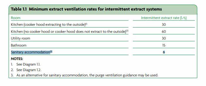
BATHROOM - A MECHANICAL FAN WITH AN EXTRACT RATE OF 15 LITRES PER SECOND DUCTED TO EXTERNAL AIR WITH 15 MINUTE OVERRUN. WINDOWS IN BATHROOMS TO BE OPENABLE TOGETHER WITH TRICKLE VENTILATION OF 4000MM2. UTILITY ROOM - WILL HAVE AN INTERMITTENT EXTRACT VENTILATION RATE OF AT LEAST 30L/S IN ACCORDANCE WITH APPROVED DOCUMENT F, TABLE 1.1
INTERNAL DWELLINGS WITH NO THROUGH VENTILATION ARE TO HAVE WHOLE HOUSE VENTILATION SYSTEMS IN ACCORDANCE WITH SPECIALIST MANUFACTURERS DESIGN, SPECIFICATION AND FULLY IN ACCORDANCE WITH THE BUILDING REGULATIONS
ALL GLAZING TO WINDOWS BELOW 800MM AND GLAZING TO DOORS BELOW 1500MM INCLUDING SIDELIGHTS WITHIN 300MM HORIZONTALLY TO BE FITTED WITH LAMINATED SAFETY GLAZING TO BS 6206 : 1981. ALL HEIGHTS TO BE MEASURED FROM FINISHED FLOOR LEVEL.
GLAZING TO BE INSTALLED IN FULL ACCORDANCE WITH AD PART L OF THE BUILDING REGULATIONS. 36MM TRIPPLE SEALED GLAZED UNITS WITH LOW-E GLASS TO BE USED. OBSCURE GLASS TO WC AND BATHROOM WINDOWS.
ALL SANITARY PIPEWORK TO BE IN ACCORDANCE WITH BS 5572 : 1994 AND THE BUILDING REGULATIONS.
SOIL AND WASTE TO BE A SINGLE STACK DRAINAGE SYSTEM TO BS 5572:1978, CONNECTING VIA A SUITABLE ADAPTER TO THE UNDERGROUND DRAINAGE SYSTEM.
DEPTH TO INVERT TO BE MINIMUM 450MM AT CONNECTIONS TO SVP.
INTERNAL VENT PIPES - REDUCE TO 75MM DIAMETER ABOVE TOPMOST CONNECTION AND TERMINATE WITH AN AIR ADMITTANCE VALVE IN ROOF SPACE WHERE POSSIBLE, OTHERWISE FIT AN AIR VENT IN THE BOX-OUT. DRAINAGE SCHEMES TO BE DESIGNED TO MEET THE REQUIREMENTS OF BUILDING REGULATIONS APPROVED DOCUMENT H, IN ACCORDANCE WITH THE INSTITUTE OF PLUMBING ENGINEERS ENGINEERING SERVICES DESIGN GUIDE AND IN ACCORDANCE WITH MANUFACTURERS INSTRUCTIONS AND BBA CERTIFICATION.
ALL WASTES TO HAVE 75MM DEEP SEAL TRAPS. ALL APPLIANCE TRAPS TO BE EITHER REMOVABLE OR FITTED WITH CLEANING EYE FACILITY. SVP - 100MM DIA PVCU TERMINATED AT PROPRIETARY ROOF VENT TILE 900MM ABOVE ANY WINDOW OPENING, OR DURGO AIR ADMITTANCE VALVE, WHERE INDICATED.
BRANCH WASTES TO BE SVP CONNECTED EITHER ABOVE CENTRE LINE OR 200MM BELOW CENTRE LINE OF WC SOIL CONNECTION. ROCKER PIPES USED WHERE DRAINS PASS THROUGH EXTERNAL WALLS. UNLESS OTHERWISE INDICATED - BATH, SINK AND SHOWER - 40MM DIA. UP TO 3M MAX. LENGTH 50MM DIA. FROM 3M - 4M MAX. LENGTH. WASH BASIN, BIDET - 32MM DIA. UP TO 1.7M MAX. LENGTH 40MM DIA. FROM 1.7M - 3M LENGTH .
100 NOMINAL DIAMETER, SALT GLAZED WARE, SUPERSLEVE OR SIMILAR OR EQUAL APPROVED. TOP RUNS MINIMUM GRADIENT OF 1:40 WITH INSPECTION CHAMBERS AT MAXIMUM 12M INTERVALS. PIPEWORK BELOW BUILDINGS TO BE ENCASED IN 100 THICK GRANULAR OR OTHER FLEXIBLE FILLING IN ACCORDANCE WITH THE MANUFACTURER'S RECOMMENDATIONS. SEE SITE DRAINAGE PLAN FOR DRAINAGE RUNS, GRADIENTS AND MANHOLE INVERTS. DRAINS PASSING THROUGH WALLS TO HAVE 50MM CLEARANCE ALL ROUND WITH LINTEL OVER.
ID THE PROPOSED BUILDING IS WITHIN 3M FROM PUBLIC SEWER, THEN A BUILD OVER AGREEMENT IS REQUIRED WITH THE THAMES WATER BEFORE THE START OF CONSTRUCTION ON SITE. PLEASE MAKE SURE THAT THE AGREEMENT IS IN-PLACE BEFORE THE START OF WORK.
SERVICES
SEAL AT FLOOR AND CEILING LEVELS THE BOXING-IN OF CONCEALED SERVICES. SEAL AROUND ALL PIPED SERVICES WHERE THEY PENETRATE OR PROJECT INTO HOLLOW CONSTRUCTIONS OR VOIDS.
7.1 EXISTING WALLS/PARTITIONS ENCLOSING STAIRWELL AT, FIRST AND SECOND FLOOR LEVEL ARE TO BE UPGRADED AS REQUIRED BY THE BUILDING CONTROL SURVEYOR TO ACHIEVE 30 MINUTES FIRE RESISTANCE.
7.2 NEW DOOR OPENINGS THROUGH THE STAIRWELL ENCLOSURE ( WITH THE EXCEPTION OF THOSE TO BATH/SHOWER ROOMS AND WCS) ARE TO BE FITTED WITH 30 MINUTE FIRE RESISTING DOOR/FRAME SETS TESTED IN ACCORDANCE WITH BS.476. POSITIONS MARKED ■ ON PLAN.
7.3 EXISTING DOOR OPENINGS THROUGH THE STAIRWELL ENCLOSURE ARE TO BE FITTED WITH 30 MINUTE FIRE RESISTING DOORS TESTED IN ACCORDANCE WITH BS476 AND FITTED WITH INTUMESCENT STRIPS POSITIONS MARKED FD20 ON PLAN.
7.4 THE STAIRWELL ENCLOSURE AND IT FIRE RESISTING ENCLOSURE SHALL CONTINUE TO A FINAL EXIT FROM THE BUILDING.
7.5 ANY NEW OR EXISTING GLAZING IN THE STAIRWAY ENCLOSURE AND ITS DOORS SHALL BE OF GEORGIAN WIRED POLISHED PLATE OR PYROGLAZE PROVIDING 30 MINUTES FIRE RESISTANCE, AND OF SAFETY OR TOUGHENED GLASS IN “CRITICAL LOCATIONS ”
7.6 MAINS POWERED SMOKE DETECTORS/ALARMS, WITH BATTERY BACKUP, CONFORMING WITH L1 STANDARD OF BS.5839 WILL BE PROVIDED IN THE STAIRWELL AT GROUND, FIRST AND SECOND FLOOR AND IN EACH HABITABLE ROOM. THE KITCHEN WILL BE PROVIDED WITH A HEAT DETECTOR.
7.7 THE PARTITIONS FORMING THE INTERNAL ENTRANCE LOBBY TO EACH FLAT WILL BE CONSTRUCTED TO ACHIEVE A MINIMUM OF 30 MINUTES FIRE RESISTANCE. ANY DOORWAYS IN THESE PARTITIONS WILL BE FITTED WITH 30 MINUTE FIRE DOORS.
7.8 STEELWORK WILL BE ENCASED OR OTHERWISE TREATED SO AS TO HAVE AT LEAST 30 MINUTES FIRE RESISTANCE."
ELECTRICAL INSTALLATION
ELECTRICAL INSTALLATION TO BE IN ACCORDANCE WITH PPROVED DOCUMENT PART P WITH LOCATIONS OF SWITCHES, SPURS ETC IN ACCORDANCE WITH APPROVED DOCUMENT PART M. REFER TO ELECTRICAL SERVICES INSTALLATION AND DRAWINGS, WHERE APPLICABLE.
EXTENDED CILLS OF APPROPRIATE LENGTH ARE TO BE ALLOWED FOR AREAS OVER RENDER / TILE HANGINGS/ STUB CILLS TO BE PROVIDED FOR WINDOWS ABOVE STONE CILL
LINTELS SIMILAR AS INDICATED IN ARCHITECTURAL DRAWINGS TO BE CONFIRMED AND DESIGNED BY STRUCTURAL ENGINEERS. GENERALLY IG GALVANIZED PRESSED METAL LINTELS OR SIMILAR WITH INTEGRAL INSULATION AND CAVITY TRAYS OVER, SIZE, TYPE, END BEARING & INSULATION TO MANUFACTURERS RECOMMENDATIONS TO SUPPORT ALL OPENINGS IN ALL INTERNAL & EXTERNAL LOAD BEARING WALLS. PROVIDE CONTINUOUS DPC CAVITY TRAYS BUILT OVER ALL LINTELS IN EXTERNAL CAVITY WALL. CAVITY TRAYS JOINED AND LAPPED MINIMUM 100MM AND SEALED BY APPROPRIATE CONTACT ADHESIVE. ALL LINTELS TO HAVE A MIN END BEARING OF 150MM EACH SIDE. PROVIDE MIN. 2 NO WEEP HOLES PER LINTEL AND AT 450MM CENTRES ABOVE LINTELS.
STRUCTURAL STEELWORK
STRUCTURAL STEEL WORK TO BS 5950.
ALL STEELWORK TO BE PAINTED WITH RED OXIDE PRIMER OR EQUIVALENT
THESE NOTES DO NOT COMPRISE A FULL SPECIFICATION. THEY ARE FOR GENERAL GUIDANCE ONLY AND THEIR PRIMARY FUNCTION IS TO ASSIST LOCAL AUTHORITY OFFICERS IN DETERMINING BUILDING REGULATION APPLICATIONS.
WHERE CLARIFICATION IS CONSIDERED NECESSARY, REFERENCE SHOULD BE MADE TO THE ARCHITECTURAL SERVICES CONSULTANT.
THE BUILDER WILL BE RESPONSIBLE FOR ENSURING THAT ALL BUILDING WORK CARRIED OUT BY THEM OR UNDER THEIR INSTRUCTIONS COMPLIES WITH THE RELEVANT CURRENT REGULATIONS, BRITISH STANDARDS AND CODES OF PRACTICE, BYE-LAWS AND MANUFACTURERS' INSTRUCTIONS.
THE U-VALUES QUOTED ABOVE ASSUME THAT A CALCULATION UNDER THE GOVERNMENT'S STANDARD ASSESSMENT PROCEDURE. BETTER VALUES MAY BE REQUIRED BY THE BUILDING REGULATION AUTHORITY TO IMPROVE THE ENERGY PERFORMANCE.
ALL ELECTRICAL WORK REQUIRED TO MEET THE REQUIREMENTS OF PART P, MUST BE DESIGNED, INSTALLED, INSPECTED AND TESTED BY A PERSON COMPETENT TO DO SO. PRIOR TO COMPLETION THE COUNCIL SHOULD BE SATISFIED THAT PART P HAS BEEN COMPLIED WITH. THIS MAY REQUIRE AN APPROPRIATE BS 7671 ELECTRICAL INSTALLATION CERTIFICATE TO BE ISSUED FOR THE WORK BY A PERSON COMETENT TO DO SO.
115MM WIDE PVC-U OR TO MATCH WITH THE EXISTING HALF ROUND DEEP FLOW GUTTERS LAID TO FALLS TO DISCHARGE INTO 63MM DIA. UPVC RAINWATER DOWNPIPES. RAINWATER DRAINAGE DESIGN TO BE IN ACCORDANCE WITH APPROVED DOCUMENT H AND VERIFIED BY THE SUPPLIER.
ALL GUTTERS ADJACENT TO TREES TO BE PROVIDED WITH EAVES GUARD.
SMOKE ALARMS
AUTOMATIC MAINS OPERATED SELF-CONTAINED SMOKE DETECTORS WITHIN EACH UNIT CONFORMING TO BS 5446 TO BE PROVIDED TO CEILINGS AT LOCATIONS INDICATED ON THE PLANS. ALARMS TO HAVE PERMANENTLY WIRED CONNECTION WITH BATTERY BACK UP, INTERLINKED ONE AT EACH FLOORAND PROVIDED WITH SEPARATE FUSED CIRCUIT AT DISTRIBUTION BOARD IN ACCORDANCE WITH CURRENT IEE REGULATION. ALARMS TO BE LOCATED MINIMUM 300MM CLEAR FROM ANY WALL OR FITTINGS, AND NOT LOCATED DIRECTLY ABOVE ANY RADIATORS. HEAT ALARMS TO BE PROVIDED IN OPEN PLAN KITCHEN.
STEELS WITHIN FLOOR CONSTRUCTION AND SUPPORTING ANY STRUCTURE TO ACHIEVE A MIN. 30 MIN. FIRE RESISTANCE BY USING INTESUMENT PAINT OR 2 LAYERS OF FIRE RESISTANT BOARDS.
ALL EXTERNAL STEEL AND METAL WORK TO BE PAINTED GLASS BLACK.
TIMBER TREATMENT
ALL SOFTWOOD TIMBERS TO BE ADEQUATELY TREATED TO PREVENT INFESTATION BY THE HOUSE LONGHORN BEETLE IN ACCORDANCE WITH CURRENT BUILDING REGULATIONS. ALL STRUCTURAL TIMBERS, EXTERNAL FRAMES, WINDOW & SOFTWOOD CLADDING SHALL BE TREATED AGAINST FUNGAL ATTACK. ALL STRUCTURAL TIMBER TO BE MARKED DRY OR KD AND TO HAVE STRESS GRADE MARK.
THE BUILDER WILL BE RESPONSIBLE FOR ENSURING THAT ALL BUILDING WORK CARRIED OUT BY THEM OR UNDER THEIR INSTRUCTIONS COMPLIES WITH THE RELEVANT CURRENT REGULATIONS, BRITISH STANDARDS AND CODES OF PRACTICE, BYE-LAWS AND MANUFACTURERS' INSTRUCTIONS.
THE U-VALUES QUOTED ABOVE ASSUME THAT A CALCULATION UNDER THE GOVERNMENT'S STANDARD ASSESSMENT PROCEDURE. BETTER VALUES MAY BE REQUIRED BY THE BUILDING REGULATION AUTHORITY TO IMPROVE THE ENERGY PERFORMANCE.


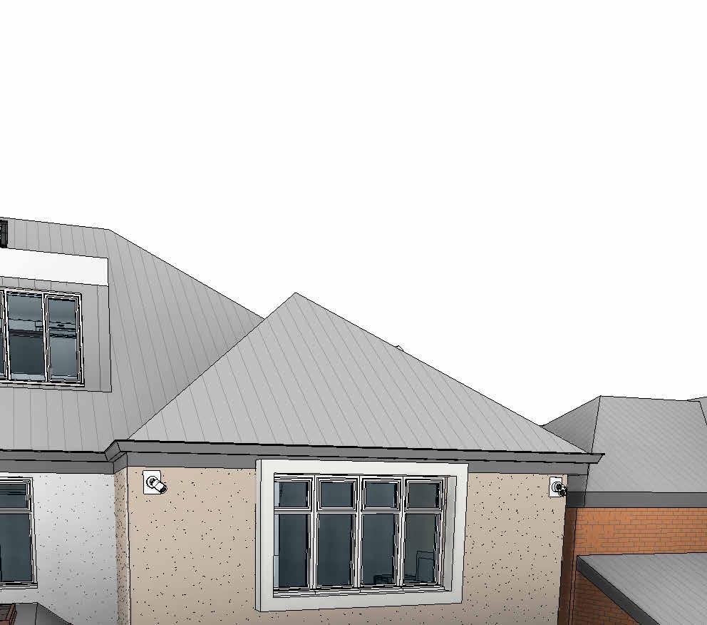
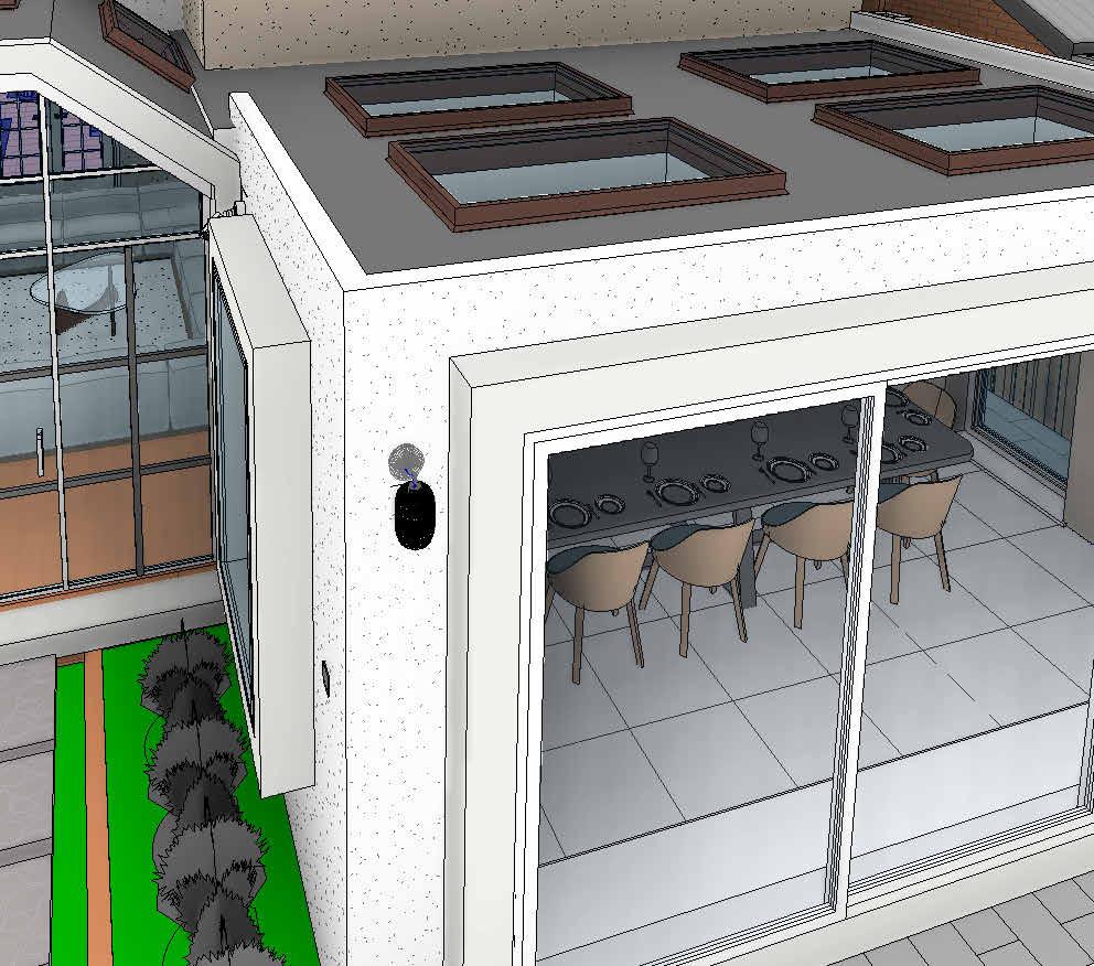
Architectural Specification for External CCTV Cameras with 4K Resolution and Power over Ethernet (PoE) for a Residential Building
1. General Overview
This specification outlines the requirements for the supply, installation, and commissioning of external CCTV cameras for a residential building. The cameras must feature 4K resolution for high-quality video capture and be powered using Power over Ethernet (PoE) technology to reduce cable clutter and enhance system reliability. This system is designed to enhance security and surveillance in key external areas of the building
2. Project Scope
•
Building Type: Residential Building
Location: External Perimeter (Entrances, Walkways, Parking Areas, Courtyards, etc.)
Cameras Required: As determined by site plan (minimum 8-12 cameras)
Resolution: 4K Ultra HD (3840 x 2160 pixels)
Power Supply: Power over Ethernet (PoE)
3. Standards and Compliance
The entire system shall comply with the following standards:
IP Rating: Minimum IP66 or higher for weatherproofing
IK Rating: IK10 for vandal resistance (especially in vulnerable areas)
IEEE Standards for PoE: IEEE 802.3af/at compliant (PoE/PoE+)
Compression Technology: H.265/H.264 video compression to reduce bandwidth and storage requirements
ONVIF Compliance: The cameras shall comply with ONVIF Profile S for easy integration with other devices
4. Camera Technical Specifications
4.1 General Features
Resolution: 4K Ultra HD (3840x2160) at 30 frames per second (fps)
Lens Type: Varifocal lens (2.8-12mm) with auto-focus capability
Field of View (FoV): Horizontal FoV between 80° and 120°, depending on lens
Infrared (IR) Range: Minimum 30 meters for night vision
Dynamic Range: Wide Dynamic Range (WDR) of 120dB or higher for better image clarity under varying lighting conditions
Image Sensor: 1/2.5" or larger CMOS sensor for optimal low-light performance
Day/Night Mode: Automatic switching between day (color) and night (black and white) modes, with integrated IR illumination
Audio Capability: Built-in microphone with noise reduction technology (optional)
4.2 Power Supply and Network
Power Source: PoE (Power over Ethernet) compliant with IEEE 802.3af/at standards
Ethernet Cable Requirements: Cat5e or Cat6 cabling to support both data transmission and power supply over PoE
Network Interface: RJ45 10/100/1000 Mbps Ethernet interface
Bandwidth: Optimized to work under 20 Mbps per stream using H.265 compression
4.3 Environmental Requirements
Weatherproofing: IP66 or higher to ensure the cameras are suitable for all weather conditions, including rain, snow, and extreme heat
Vandal Resistance: IK10 vandal-proof rating, particularly in exposed or public areas
Operating Temperature: -30°C to +60°C
Humidity: 10% to 90% non-condensing
4.4 Mounting and Housing
Mount Type: Wall, ceiling, or pole mount, depending on site-specific requirements
Material: Anti-corrosion, UV-resistant housing made of aluminum or stainless steel
Tamper Detection: Alerts for unauthorized attempts to interfere with the camera (optional)
4.5 Smart Features (Optional)
Motion Detection: Configurable motion detection with customizable zones
Intrusion Detection: Notification alerts when motion is detected in pre-defined areas
Line-Crossing Detection: Alerts when virtual boundary lines are crossed
Facial Recognition/License Plate Recognition: Optional AI features for advanced security applications
Storage: Local SD card slot (minimum 128 GB support), plus compatibility with centralized network video recorders (NVRs)
5. Installation Requirements
5.1 Cabling
Ethernet Cable: Minimum Category 5e or 6 UTP/FTP cable to support both network connectivity and PoE
Cable Runs: All cable runs shall comply with industry standards (maximum 100m for direct PoE from a switch)
Conduit/Trunking: Outdoor-rated conduits for weather protection and enhanced durability in harsh environments
Grounding and Surge Protection: Appropriate grounding and surge protection measures should be included for all external cables
5.2 Mounting Locations
Entrances and Exits: High-resolution cameras must cover all building entrances and exits
Perimeter Walls: Cameras shall be mounted to cover the external perimeter walls, ensuring no blind spots
Parking Areas: Coverage of all parking spaces and vehicle entry/exit points
Walkways and Common Areas: Strategic placement to monitor areas where foot traffic is high
Height of Cameras: Install cameras at a minimum height of 2.5 meters to avoid tampering, but no higher than 5 meters to ensure effective coverage and facial recognition capability
6. Network and Storage Requirements
6.1 Network
Switches: All network switches should be PoE-capable and support the required power draw of the cameras. If cameras are located far from power sources, PoE injectors or mid-span PoE devices may be required.
Bandwidth: A minimum of 50 Mbps upload speed is recommended for remote monitoring of live video streams in 4K resolution
6.2 Storage
NVR Compatibility: The cameras shall be compatible with NVRs (Network Video Recorders) that support 4K resolution recording and H.265/H.264 video compression.
Recording Capacity: Based on continuous 24/7 recording, a minimum of 30 days of footage retention shall be available, with scalable storage solutions or 6 TeraBytes of Minimum Hard Disk Drive space.
Cloud Storage (Optional): The system should offer the capability to upload footage to a secure cloud storage solution for offsite backups.
7. System Management and Monitoring
7.1 Control Software
VMS (Video Management System): The system must be capable of integrating with a VMS, allowing for remote monitoring, playback, and video management from a central interface (PC or mobile)
User Access Control: Role-based access to the system with varying levels of permissions (e.g., view-only, administrative control, etc.)
7.2 Mobile Application
Mobile Viewing: The system should support live view and playback of footage on mobile applications (iOS and Android) with push notifications for alarms or motion detection events
7.3 Alarms and Notifications
Alarm Triggering: The system should be configured to send notifications via email or SMS in the event of motion detection or tampering
Integration with Alarm System: The CCTV system should have the capability to be integrated with the building's existing alarm system, if applicable
8. Testing and Commissioning
System Testing: Upon completion of installation, the entire system shall be tested to ensure full functionality of each camera, power supply, and recording system
Quality Check: Ensure 4K video quality, clarity in day/night modes, and effectiveness of all smart detection features
Training: Provide training for building management or residents on how to use the system, including mobile app features and alarm notifications
9. Documentation and Warranty
As-Built Drawings: Detailed installation drawings showing the camera locations and cable routes
Operation Manuals: Provide user manuals for the CCTV system hardware and software
Warranty: A minimum 3-year warranty on all CCTV equipment including cameras, cabling, NVRs, and switches
10. Conclusion
This specification ensures the installation of a high-quality, reliable, and scalable external CCTV system to enhance security at the residential building. The use of IP68 4K resolution cameras powered by PoE ensures clarity in surveillance footage, while reducing the complexity of the installation by combining power and data through a single cable.

SB-02/ UKC203x203x46

/Padstone 450x100x215mm
/Padstone 300x100x215mm
/Padstone 450x100x215mm
SB05/ UKC203x203x60

SB05/ UKC203x203x60
SB-03/ UKC203x203x46
/Padstone 450x100x215mm
/Padstone 450x100x215mm
SB-06/ UKC203x203x46
UKC203x203x46 SB-05A/ UKB203x102x23
/Padstone 550x100x275mm /Padstone 650x100x325mm
SHS80x80x8
SB01/ UKC203x203x46
UKC254x254x167


SP3SHS80x80x8
SB01 / UKC203x203x46
TP3100x100 TP5100x100
SB-05A/ UKB203x102x23
UKC203x203x46
SB-09/ SHS80x80x8
SB-09 / SHS80x80x8
SB-09/ SHS80x80x8
/Padstone 400x100x215mm
SB-02/ UKC203x203x46
TP6100x100 100x100 TP4100x100 / Padstone 450x100x215mm Padstone 450x100x215mm
SB-03/ UKC203x203x46
SB04/ UKC203x203x60 SP1SHS100x100x10 TP6100x100
/ Padstone 550x100x275mm
SB-11 / UKC254x254x167
SB-06/ UKC203x203x46 TP6100x100
SP4SHS100x100x10
SB-08/ UKB203x102x23
SP3SHS80x80x8
SB-10 / SHS100x100x10
SB05 / UKC203x203x60
SB-07 / UKC203x203x46
/Padstone 450x100x215mm
SB05 / UKC203x203x60
SP4SHS100x100x10
/Padstone 300x100x215mm
SP5SHS200x200x10
1.0 GENERAL
1.1 DO NOT SCALE DRAWINGS. THE CONTRACTOR IS TO CHECK ALL DIMENSIONS ON SITE BEFORE CARRYING OUT ANY WORKS.
1.2 THIS SPECIFICATION TOGETHER WITH THE STRUCTURAL ENGINEER'S DRAWINGS AND CALCULATIONS ARE TO BE READ IN CONJUNCTION WITH ARCHITECT'S AND ALL OTHER CONSULTANT'S DRAWINGS AND SPECIFICATIONS, WHICH SHOULD BE USED TO VERIFY LAYOUT, SETTING OUT, FINISHES ETC.,. ANY DISCREPANCIES ARE TO BE REPORTED TO THE ARCHITECT BEFORE PROCEEDING WITH THE WORKS.
1.3 THE CONTRACTOR MUST ENSURE THAT THE CLIENT HAS AGREED ALL NECESSARY PARTY WALL NOTICES PRIOR TO CARRYING OUT WORKS UNDER, ON OR ADJACENT TO PARTY WALL.
1.4 SETTING OUT DETAILS ARE SHOWN ON THE ARCHITECT'S DRAWINGS UNLESS NOTED OTHERWISE ON THE DRAWINGS.
1.5 THE CONTRACTOR IS TO INFORM THE ARCHITECT AND STRUCTURAL ENGINEER IF THE EXISTING FABRIC, INCLUDING FOUNDATIONS, IS OPENED UP AND FOUND TO BE INADEQUATE, UNSUITABLE TO SUPPORT THE PROPOSED WORKS, OR AT VARIANCE FROM THE DETAILS SHOWN ON THE DRAWINGS.
1.6 ITEMS NOTED ON THE DRAWINGS "TO BE VERIFIED ON SITE" ARE TO BE EXPOSED BY THE CONTRACTOR FOR INSPECTION BY THE STRUCTURAL ENGINEER AT THE EARLIEST OPPORTUNITY.
1.7 HOLES OR CHASES MUST NOT BE CUT THROUGH ANY STRUCTURAL MEMBERS WITHOUT THE WRITTEN CONSENT OF THE STRUCTURAL ENGINEER.
1.8 NOTHING INCLUDED OR OMITTED FROM THIS OUTLINE SPECIFICATION WILL RELIEVE THE CONTRACTOR OF HIS DUTY TO CARRY OUT THE WORKS IN ACCORDANCE WITH CURRENT STANDARDS OF SAFETY AND GOOD BUILDING PRACTICE.
2.0 TOLERANCES
2.1 ALL TOLERANCES ARE TO BE AGREED WITH THE ARCHITECT, AND THE CONTRACTOR WILL BE RESPONSIBLE FOR ENSURING THAT SUFFICIENT TOLERANCES ARE PROVIDED AND INTEGRATED THROUGHOUT ALL ELEMENTS OF THE WORKS.
2.2 THE CONTRACTOR IS TO TAKE ACCOUNT OF TOLERANCES DETAILED ELSEWHERE IN THE DRAWINGS, APPENDED SPECIFICATIONS, AND BRITISH STANDARDS WHEN COMPLYING WITH THE ABOVE CLAUSE
3.0 MATERIALS AND WORKMANSHIP
3.1 ALL ARTICLES, MATERIALS AND GOODS SHALL BE NEW AND OF GOOD QUALITY, SUITABLE FOR THE REQUIRED PURPOSE AND SHALL CONFORM TO THE APPROPRIATE BRITISH STANDARD WHERE SUCH EXISTS. WHERE REFERENCES TO THE ABOVE ARE MADE IT SHALL BE INFERRED THAT THE LATEST EDITION APPLIES, TOGETHER WITH SUBSEQUENT AMENDMENTS, UNLESS OTHERWISE SPECIFIED.
4.0 TEMPORARY WORKS AND STABILITY
4.1 THE CONTRACTOR IS ENTIRELY RESPONSIBLE FOR MAINTAINING THE STABILITY OF ALL EXISTING BUILDINGS AND STRUCTURES, WITHIN AND ADJACENT TO THE WORKS, AND OF ALL THE WORKS FROM THE DATE OF POSSESSION OF THE SITE UNTIL PRACTICAL COMPLETION OF THE WORKS.
4.2 THE CONTRACTOR SHALL DESIGN, INSTALL AND MAINTAIN ALL NECESSARY TEMPORARY WORKS AND SHALL ADVISE BOTH THE ARCHITECT AND STRUCTURAL ENGINEER AT LEAST TEN WORKING DAYS FROM COMMENCEMENT OF THE WORKS, OF HIS PROPOSALS FOR TEMPORARY SUPPORTS AND SEQUENCE OF CONSTRUCTION FOR THE WORKS. THESE PROPOSALS SHALL BE SUPPORTED BY DESIGN CALCULATIONS IFREQUESTED.
4.3 THE DESIGN OF TEMPORARY WORKS SHALL INCLUDE AN ASSESSMENT OF THE LOADS TO BE RESISTED AND IS TO BE UNDERTAKEN BY A COMPETENT PERSON. DUE REGARD SHALL BE GIVEN TO LATERAL STABILITY AS WELL AS TO THE SUPPORT OF VERTICAL LOADS. TEMPORARY SHORING TO VERTICAL ELEMENTS (EG. PARTY WALLS) TO BE DESIGNED TO RESIST A MINIMUM OF 5% OF DEAD LOAD, SUPPORTED BY THE PARTICULAR ELEMENT, ABOVE ANY LEVEL OF THE POINT OF CONTACT OF THE SHORING.
4.4 THE CONTRACTOR IS TO FAMILIARISE HIMSELF WITH THE BUILDING AND ITS STRUCTURE SO THAT HE IS AWARE OF THE NATURE AND MAGNITUDE OF THE LOADS TO BE SUPPORTED.
4.5 PARTICULAR CARE IS TO BE TAKEN TO ENSURE THAT TEMPORARY PROPS REMAIN ADEQUATELY SEATED AND TIGHTENED SO THAT SUPPORT TO THE STRUCTURE ABOVE IS NOT ALLOWED TO YIELD DURING BUILDING OPERATIONS.
4.6 THE CONTRACTOR IS TO ENSURE THAT TEMPORARILY PROPPED STRUCTURE IS ADEQUATELY WEDGED, PINNED OR PACKED OFF THE PERMANENT WORKS PRIOR TO REMOVAL OF ANY TEMPORARY SUPPORTS.
4.7 THE CONTRACTOR SHALL ENSURE THAT ANY COMPLETED OR PARTIALLY COMPLETED STRUCTURAL ELEMENT IS NOT OVERLOADED. DETAILS OF DESIGN LOADS MAY BE OBTAINED FROM THE STRUCTURAL ENGINEER.
4.8 ALL TEMPORARY WORKS TO SUPPORT THE SIDES OF EXCAVATIONS FOR NEW FOUNDATIONS SHALL BE DESIGNED IN ACCORDANCE WITH BS 8000 PART 1: 1989 AND ANY OTHER APPROVED DOCUMENTS.
4.9 EXCAVATIONS SHALL IN NO CIRCUMSTANCES ENCROACH WITHIN 45° OF THE BOTTOM NEAR SIDE OF ANY EXISTING FOOTING.
5.0 DEMOLITION
5.1 DEMOLITION IS TO BE CARRIED OUT TO AND IN ACCORDANCE WITH BS 6187: 1982, HEALTH AND SAFETY EXECUTIVE GUIDANCE NOTE GS 29/1 PARAGRAPH 32, AND ANY OTHER RELEVANT STATUTORY UNDERTAKINGS OR REGULATIONS.
5.2 DEMOLITION IS TO BE UNDERTAKEN IN THE REVERSE ORDER OF CONSTRUCTION. NO PART OF THE STRUCTURE IS TO BE LEFT IN AN UNSUPPORTED CONDITION OVERNIGHT OR FOR LONG PERIODS.
5.3 DEMOLITION IS TO BE UNDERTAKEN IN A MANNER WHICH AVOIDS EXCESSIVE NOISE AND NUISANCE. ALL WORK IS TO BE WELL-WATERED TO MINIMISE DUST. ALL MATERIAL IS TO BE CARTED AWAY FROM SITE AS SOON AS PRACTICABLE.
6.0 EXCAVATING AND FILLING
6.1 TRIAL PITS TO BE CARRIED OUT TO INDICATE UNDERLYING SOIL.
6.2 GROUND WATER LEVEL ON THE SITE IS NOT KNOWN.
6.3 INSPECT ALL AVAILABLE DRAWINGS AND MAKE ENQUIRIES ABOUT EXISTING SERVICES ON SITE. VERIFY POSITIONS AND DEPTH OF ALL SERVICES BEFORE COMMENCEMENT OF WORK ON SITE. SERVICES WHICH ARE BEING RETAINED DURING ANY PHASE OF THE WORKS ARE TO BE PROTECTED.
6.4 BEFORE STARTING WORK VERIFY WITH THE ARCHITECT WHICH EXISTING FENCES, GATES, WALLS, PAVED AREAS, TREES, SHRUBS, HEDGES, BUSHES AND ANY OTHER SITE FEATURES ARE TO BE REMOVED. MATERIALS ARISING ARE TO BE REMOVED FROM SITE.
6.5 WORKMANSHIP FOR EXCAVATING TO COMPLY WITH BS 8000: PART 1, SECTIONS 3.1, 3.2 AND 3.3.
6.6 WHERE AN EXCAVATION ENCROACHES BELOW A LINE DRAWN AT AN ANGLE OF 45° FROM THE HORIZONTAL FROM THE NEAREST FORMATION LEVEL OF ANOTHER HIGHER EXCAVATION, THE LOWER EXCAVATION, ALL WORK WITHIN IT AND BACKFILLING THERETO MUST BE COMPLETED BEFORE THE HIGHER EXCAVATION IS MADE.
6.7 MAKE ADVANCE ARRANGEMENTS WITH THE BUILDING CONTROL OFFICER AND/OR ARCHITECT FOR INSPECTION OF FOUNDATIONS AND TRENCHES REQUESTED AT THE BEGINNING OF THE WORKS.REMOVE THE LAST 150mm OF EXCAVATIONS JUST BEFORE INSPECTION. TRIM EXCAVATIONS TO REQUIRED PROFILES AND LEVELS, AND REMOVE ALL LOOSE MATERIALS. UNLESS OTHERWISE INSTRUCTED SEAL FORMATIONS WITHIN 4 HOURS OF INSPECTION WITH CONCRETE OR OTHER SPECIFIED FILL.
6.8 BACKFILL ANY EXCAVATIONS FOR FOUNDATIONS TAKEN DEEPER THAN REQUIRED WITH LEAN MIX CONCRETE. EXCAVATIONS OTHER THAN FOUNDATIONS TAKEN DEEPER THAN REQUIRED MAY BE BACKFILLED WITH WELL GRADED GRANULAR MATERIAL.
6.9 HARDCORE TO BE GRANULAR MATERIAL, FREE FROM HARMFUL MATTER, WELL GRADED, PASSING A 75mm BS SIEVE AND ONE OF THE FOLLOWING: - CRUSHED CONCRETE, BRICK OR TILE, FREE FROM OLD PLASTER. - GRAVEL. SPREAD AND LEVEL BOTH BACKFILLING AND GENERAL FILLING IN LAYERS NOT EXCEEDING 150mm. THOROUGHLY COMPACT EACH LAYER WITH A VIBRATORY ROLLER, VIBRATING PLATE COMPACTOR, VIBRO- TAMPER, POWER RAMMER OR OTHER SUITABLE MEANS APPROPRIATE TO THE AREA BEING WORKED.
6.10 HARDCORE UNDER GROUND BEARING CONCRETE SLABS TO BE AS ABOVE AND NOT LESS THAN 150mm THICK, UNLESS NOTED OTHERWISE ON THE DRAWINGS. EXCAVATE EXTRA MATERIAL AS NECESSARY. INCREASE THICKNESS OF HARDCORE AS NECESSARY TO MAKE UP LEVELS FROM STRIPPED SITE LEVELS TO UNDERSIDE OF SLABS.
6.11 SURFACES OVER HARDCORE TO RECEIVE SHEET OVERLAYS OR CONCRETE TO BE BLINDED WITH SUFFICIENT SAND OR FINE GRAVEL TO FILL INTERSTICES AND PROVIDE A CLOSE SMOOTH SURFACE (50mm MIN THICKNESS), UNLESS NOTED OTHERWISE ON THE DRAWINGS. PERMISSIBLE DEVIATIONS ON SURFACE LEVEL TO BE + 0-15mm.
6.12 MINIMUM VOID UNDER SUSPENDED GROUND FLOORS TO BE 225mm FOR PRECAST CONCRETE AND 300mm FOR TIMBER FLOORS. SUSPENDED IN-SITU CONCRETE FLOORS SHALL BE CAST OVER A SUITABLE VOID FORMER TO PROVIDE A VOID OF 150MM UNDER THE SLAB, UNLESS NOTED OTHERWISE ON THE DRAWINGS.
7.0 FOUNDATIONS
7.1 FOUNDATIONS ARE TO BE CAST TO THE PROFILES INDICATED ON THE DRAWINGS. THEY ARE TO BE CAST SYMMETRICALLY ABOUT PIERS, STANCHIONS OR WALLS, UNLESS NOTED OTHERWISE ON THE DRAWINGS. ALL FORMATION LEVELS FOR FOUNDATIONS TO BE AGREED WITH BUILDING INSPECTOR ON SITE.
7.2 NEW FOUNDATIONS HAVE BEEN DESIGNED TO IMPOSE A SAFE BEARING PRESSURE OF 100kN/m2 ON CLAY 1100mm BELOW FINAL EXTERNAL GROUND LEVEL. THE CONTRACTOR IS TO ENSURE THAT ALL NEW FOUNDATIONS BEAR A MINIMUM OF 150mm ONTO FIRM CLAY. WHERE POOR GROUND CONDITIONS ARE ENCOUNTERED OR THE BUILDING CONTROL OFFICER REQUESTS AMENDMENTS THE STRUCTURAL ENGINEER IS TO BE NOTIFIED IMMEDIATELY.
7.3 WHERE TREE ROOTS ARE ENCOUNTERED, FOUNDATIONS ARE TO EXTEND 600MM BELOW THE LAST TRACE OF ANY ROOT ACTIVITY.
7.4 FOUNDATIONS SITED WITHIN A ZONE 1.25 X MATURE TREE HEIGHT FOR HIGH WATER DEMAND TREES, 0.75 X MATURE TREE HEIGHT FOR MODERATE WATER DEMAND TREES AND 0.50 X MATURE TREE HEIGHT FOR LOW WATER DEMAND TREES WHICH ARE TO REMAIN OR TO BE REMOVED, OR OVER TREES AFTER REMOVAL, ARE TO BE PROTECTED AGAINST CLAY HEAVE AS FOLLOWS:
(i) TRENCH FILL FOUNDATIONS
PROVIDE COMPRESSIBLE MATERIAL AGAINST INSIDE FACE OF ALL EXTERNAL WALL FOUNDATIONS GREATER THAN 1.5M DEEP TO GIVE A 35mm VOID. THE COMPRESSIBLE MATERIAL IS TO BE POSITIONED 500mm ABOVE THE BOTTOM OF THE FOUNDATION.
(ii) PIER AND GROUND BEAM FOUNDATIONS
PROVIDE COMPRESSIBLE MATERIAL AGAINST FACES OF ALL PIER FOUNDATIONS GREATER THAN 1.5m DEEP TO GIVE A 35mm VOID. THE COMPRESSIBLE MATERIAL IS TO BE POSITIONED 500mm ABOVE THE BOTTOM OF THE FOUNDATIONS. ALSO, PROVIDE COMPRESSIBLE MATERIAL OR VOID FORMER BELOW ALL GROUND BEAMS AND AGAINST THE INSIDE FACE OF EXTERNAL GROUND BEAMS TO GIVE A 150mm AND 35mm VOID RESPECTIVELY.
(iii) PILE AND GROUND BEAM FOUNDATIONS PROVIDE COMPRESSIBLE MATERIAL OR VOID FORMER BELOW ALL GROUND BEAMS AND AGAINST THE INSIDE FACE OF THE EXTERNAL GROUND BEAMS TO GIVE A 150mm AND 35mm VOID RESPECTIVELY. PILES ARE TO BE DESIGNED IN ACCORDANCE WITH THE PERFORMANCE PILING SPECIFICATION.
7.5 WHERE CONSTRUCTION JOINTS IN TRENCH FILL FOUNDATIONS ARE UNAVOIDABLE THEY SHOULD NOT BE POSITIONED NEAR A RETURN IN THE FOUNDATION. CONSTRUCTION JOINTS SHOULD BE FORMED USING 4 NO. 20mm DIAMETER AND 1200 LONG HIGH TENSILE DOWEL BARS CAST 600mm INTO ADJACENT SECTIONS.
7.6 THE CONTRACTOR IS TO ENSURE THAT THE BUILDING CONTROL OFFICER IS NOTIFIED FOR HIS INSPECTION OF THE BOTTOM OF ALL FOUNDATIONS PRIOR TO CONCRETING
8.0 INSITU CONCRETE
8.1 MATERIALS AND WORKMANSHIP ARE TO COMPLY WITH BS 8110.
8.2 CONCRETE FOR NEW FOUNDATIONS IS TO BE DESIGNATED MIX FND 2 TO BS 5328. "SUITABLE FOR CLASS 2 SULPHATE CONDITIONS"
8.3 CONCRETE FOR REINFORCED CONCRETE STRUCTURES, INCLUDING GROUND BEARING SLABS, IS TO BE DESIGNATED MIX RC35 TO BS 5328.
8.4 CONCRETE FOR THE ENCASEMENT OF STEEL BEAMS AND FOR PADSTONES IS TO BE GEN3 TO BS 5328 WITH 10mm MAXIMUM AGGREGATE AND 260 kg/m3 OF CEMENT
8.5 READY MIX CONCRETE IS TO BE USED UNLESS OTHERWISE ALLOWED BY THE STRUCTURAL ENGINEER. THIS MUST BE OBTAINED FROM A PLANT WHICH HOLDS A CURRENT CERTIFICATE OF ACCREDITATION UNDER THE QUALITY SCHEME FOR READY MIX CONCRETE. DETAILS OF CEMENT TYPE, AGGREGATE GRADING AND SOURCES, WITH CHLORIDE AND SULPHATE CONTENT OF MIXES TO BE SUBMITTED TO THE STRUCTURAL ENGINEER FOR HIS APPROVAL PRIOR TO ORDERING ANY CONCRETE.
8.6 THE USE OF SITE MIXED CONCRETE FOR STRUCTURAL ELEMENTS MAY ONLY BE USED FOLLOWING THE WRITTEN APPROVAL OF THE STRUCTURAL ENGINEER. BATCHING AND MIXING EQUIPMENT WILL NEED TO COMPLY WITH BS 1305 AND BS 4251.
8.7 THE CONTRACTOR IS RESPONSIBLE FOR THE DESIGN AND INSTALLATION OF ALL FORMWORK. DESIGN AND STRIKING OF THE FORMWORK IS TO BE IN ACCORDANCE WITH BS 8110.
8.8 DO NOT PLACE CONCRETE WHEN THE AMBIENT AIR TEMPERATURE IS LESS THAN 5°C.
8.9 ALL HOLES SHALL BE FORMED AND ALL INSERTS CAST IN AT THE TIME OF POURING CONCRETE. NO PART OF THE CONCRETE WORKS SHALL BE DRILLED OR CUT AWAY WITHOUT THE APPROVAL OF THE STRUCTURAL ENGINEER.
8.10 REINFORCEMENT SHALL BE:
(i) PLAIN BARS TO BS 4449, GRADE 250 (MILD STEEL), PREFIX R ON DRAWINGS AND SCHEDULE. OR (ii) DEFORMED BARS TO BS 4449, OR BS 4461, GRADE 460 (HIGH YIELD) TYPE 2, PREFIX T ON DRAWINGS AND SCHEDULES. MESH TO BS 4483.
8.11 REINFORCEMENT SHALL BE FIXED ADEQUATELY USING TYING WIRE OR STEEL CLIPS. CONCRETE COVER IS TO BE AS SPECIFIED ON THE DRAWINGS. CHAIRS AND SPACERS ARE TO BE PROVIDED BY THE CONTRACTOR AS NECESSARY TO MAINTAIN THE SPECIFIED COVER.
8.12 UNLESS NOTED OTHERWISE ON DRAWINGS, ALL REINFORCEMENT IS TO BE LAPPED 50D (WHERE D IS DIAMETER OF THE SMALLER BAR).
8.13 THE RATE OF SAMPLING FOR COMPRESSIVE TESTING OF CONCRETE S TO BE AGREED WITH THE STRUCTURAL ENGINEER PRIOR TO COMMENCEMENT OF ANY CONCRETE WORKS
8.14 USE MECHANICAL VIBRATION TO FULLY COMPACT CONCRETE FOR STRUCTURAL ELEMENTS. COMPACT CONCRETE TO FULL DEPTH (UNTIL AIR BUBBLES CEASE TO APPEAR ON THE TOP SURFACE), ESPECIALLY AROUND REINFORCEMENT, CAST-IN ACCESSORIES, INTO CORNERS OF FORMWORK AND AT JOINTS.
8.15 BEFORE PLACING STRUCTURAL CONCRETE (NOT BLINDING) ON HARDCORE OR OTHER ABSORBENT SUBSTRATES LAY BUILDING PAPER TO BS 1521 CLASS 3 OR POLYTHENE SHEET 250 MICRONS THICK. LAP EDGES 150MM. THIS IS NOT A DPM - SEE ARCHITECT'S DETAILS FOR THIS.
8.16 STRIKE FORMWORK WITHOUT DISTURBING, DAMAGING OR OVERLOADING STRUCTURE, AND WITHOUT DISTURBING PROPS. NOTWITHSTANDING OTHER CLAUSES IN THIS SPECIFICATION AND ANY CHECKING OR APPROVALS BY THE CA, THE RESPONSIBILITY FOR SAFE REMOVAL OF ANY PART OF THE FORMWORK AND ANY SUPPORTS WITHOUT DAMAGING THE STRUCTURE RESTS WITH THE CONTRACTOR.
8.17 MINIMUM PERIODS: THE FOLLOWING PERIODS (IN DAYS) FOR RETAINING FORMWORK IN POSITION BEFORE STRIKING APPLY TO CLASS 42.5 OR SULFATE- RESISTING PORTLAND CEMENT CONCRETE WITH NO CEMENT REPLACEMENT MATERIALS OR ADMIXTURES:
SUBMIT DETAILS OF PROPOSED PERIODS FOR MIXES USING ADMIXTURES OR OTHER TYPES OF CEMENT.
MINIMUM PERIODS: ALTERNATIVE METHODS OF DETERMINING MINIMUM PERIODS FOR RETAINING FORMWORK IN POSITION MAY BE SUBMITTED FOR APPROVAL. ACCEPT RESPONSIBILITY FOR COST OF CHECKING OF PROPOSALS BY CA AND FOR ANY TESTING.
8.18 FORMED FINISHES
BASIC FINISH: NO PARTICULAR REQUIREMENTS, EXCEPT THOSE FOR TOLERANCES AND FULL COMPACTION. FINISH TO RECEIVE ASPHALT TANKING: PRODUCE AN EVEN FINISH WITH A SHEET MATERIAL (E.G. PLYWOOD), SUITABLE TO RECEIVE ASPHALT, AND ACCEPTABLE TO ASPHALT CONTRACTOR. AVOID EXCESSIVE USE OF RELEASE AGENTS. ABRUPT IRREGULARITIES TO BE NOT GREATER THAN 3mm. GRADUAL IRREGULARITIES, EXPRESSED AS A MAXIMUM PERMISSIBLE DEVIATION FROM A 1mm STRAIGHT EDGE, TO BE NOT GREATER THAN 3mm. BLOWHOLES LESS THAN 10mm IN DIAMETER WILL BE PERMITTED BUT OTHERWISE SURFACE TO BE FREE FROM VOIDS, HONEYCOMBING, SEGREGATION AND OTHER LARGE DEFECTS.
8.19 TOLERANCES
UNLESS SHOWN OTHERWISE ON THE DRAWINGS, THE MAXIMUM PERMITTED DEVIATIONS OF DIMENSIONS AND LEVELS IN THE COMPLETED STRUCTURE FROM THOSE SHOWN ON, OR CALCULABLE FROM, THE DRAWINGS ARE SET OUT BELOW.
THE FIGURES GIVEN INCLUDE, BUT ARE NOT LIMITED TO, SUCH VARIABLES AS:
a) POSITION ON PLAN OF ANY POINT OF THE STRUCTURE FROM NEAREST GRID LINE.
b) VERTICALLY.
c) CROSS SECTION AND OTHER LINEAR DIMENSION OF MEMBER.
d) CLEAR HORIZONTAL AND VERTICAL DIMENSIONS BETWEEN MEMBERS.
e) BOW AND CAMBER OTHER THAN SPECIFIED CAMBER
f) TWIST (THE DISTANCE OF ANY CORNER FROM A PLANE CONTAINING THE OTHER THREE CORNERS).
g) SQUARENESS OF CORNERS (THE LONGER OF TWO ADJACENT SIDES SHALL BE TAKEN AS THE BASE LINE). DEVIATION IS
h) RELATED TO THE LENGTH OF THE SHORTER SIDE.
9.0
9.1 WORKMANSHIP IS TO COMPLY GENERALLY WITH BS 5628 PARTS 1 & 3. BRICKWORK TO BE BS 3921. BLOCKWORK TO BE TO BS 6073.
9.2 NEW BRICKWORK ABOVE DPC IS TO BE A MINIMUM OF CLASS 3 CLAY BRICKS (20 N/mm2) SET IN 1:1:6 MORTAR UNLESS NOTED OTHERWISE ON THE DRAWINGS.
9.3 NEW BLOCKWORK ABOVE DPC IS TO BE OF MINIMUM STRENGTH OF 10.4N/mm2 SET IN 1:1:6 MORTAR, UNLESS NOTED OTHERWISE ON THE DRAWINGS.
9.4 BRICKWORK AND BLOCKWORK ARE TO BE LAID PROPERLY BONDED AS AGREED WITH THE ARCHITECT AND FULLY BONDED INTO EXISTING WORK OR AS SPECIFIED OTHERWISE ON THE DRAWINGS. ALL PERPENDS MUST BE FULLY FILLED WITH MORTAR.
9.5 NEW FACING BRICKWORK BELOW DPC IS TO BE MINIMUM FL DURABILITY BRICKS SET IN 1:3 MORTAR WITH SRPC, UNLESS NOTED OTHERWISE ON THE DRAWINGS.
9.6 ALL OTHER MASONRY BELOW DPC IS TO BE CLASS B ENGINEERING BRICKS, SET IN 1:3 MORTAR WITH SRPC OR AS NOTED OTHERWISE ON THE DRAWINGS.
9.7 DO NOT LAY MASONRY WHEN THE AMBIENT AIR TEMPERATURE IS LESS THAN 5°C.
9.8 CAVITY WALL TIES SHALL BE STAINLESS STEEL DOUBLE TRIANGLE TYPE TIES TO BS 1243, FOR CAVITIES OF 75mm OR LESS, SPACED AT 450mm c/c VERTICALLY, 900CRS HORIZONTALLY STAGGERED, AND AT 225mm c/c VERTICALLY 150mm FROM ALL OPENINGS, CORNERS, MOVEMENT JOINTS AND REVEALS. MINIMUM EMBEDMENT TO BE 50mm INTO EACH MASONRY LEAF. CAVITIES OF GREATER THAN 75MM WIDTH TO HAVE STAINLESS STEEL VERTICAL TWIST TIES AT SIMILAR CENTRES.
9.9 MOVEMENT JOINTS IN FACING BRICKWORK ARE TO BE FORMED BY BUILDING IN 'AEROFIL' JOINT FILLER BY SERVICISED LTD, AS THE WORKS PROCEED ENSURING NO PROJECTIONS INTO CAVITIES. IN JOINTS TO BE POINTED WITH SEALANT, POSITION FILLER ACCURATELY AT THE RECOMMENDED DISTANCE FROM THE FACE OF WALL. LEAVE JOINTS OPEN FOR AS LONG AS POSSIBLE BEFORE SEALING WITH APPROPRIATE SEALANT TO ARCHITECTS' SPECIFICATION.
9.10 WHERE PINNING UP TO SOFFITS IS REQUIRED, COMPLETELY FILL THE JOINT AT THE TOP OF LOADBEARING WALLS WITH 1:3 CEMENT/SHARP SAND DRY PACK MORTAR, WELL RAMMED INTO POSITION USING TEMPORARY SHUTTERING.
9.11 CARRY UP WORK WITH NO PORTION OR SECTION OF WALL MORE THAN 1.2m ABOVE ANOTHER AT ANY TIME, RAKING BACK BETWEEN LEVELS. DO NOT CARRY UP WORK HIGHER THAN 1.5m IN ONE DAY. 9.12 SPACING OF MOVEMENT JOINTS IN BRICKWORK AND BLOCKWORK ARE NOT TO EXCEED 12.0m AND 6.0M, RESPECTIVELY.
9.13 PROVIDE STAINLESS STEEL BED JOINT REINFORCEMENT, "BRICKTOR" BY BRC, AT 225mm AND 450mm VERTICAL CENTRES ABOVE EXTERNAL DOORS & ALSO ABOVE AND BELOW WINDOWS. BED JOINT REINFORCEMENT TO EXTENT 500mm MINIMUM PAST DOOR / WINDOW LINE.
10.0 STRUCTURAL TIMBER
10.1 NEW TIMBER IN THE WORKS IS TO BE SELECTED STRUCTURAL TIMBER NOT INFERIOR TO EUROPEAN REDWOOD/WHITEWOOD GRADE SC3 TO BS 5268: PART 2, UNLESS NOTED OTHERWISE ON THE DRAWINGS.
10.2 NEW TIMBER IN THE WORKS IS TO BE VACUUM IMPREGNATED WITH PRESERVATIVE TO BS 5268: PART 5 AND THE MANUFACTURER'S RECOMMENDATIONS. CUT ENDS ARE TO BE THOROUGHLY TREATED WITH BRUSH APPLIED COATS OF APPROPRIATE PRESERVATIVE BEFORE FIXING. ALL PRESERVATIVES ARE TO BE TO THE ARCHITECT'S APPROVAL.
10.3 STRUCTURAL TIMBERS MAY ONLY BE DRILLED OR CUT FOR SERVICES AS NOTED BELOW. NOTCHES IN THE JOISTS ARE TO BE AT THE TOP AND LOCATED BETWEEN 0.1 AND 0.25 OF THE SPAN FROM THE SUPPORT. NOTCH CANNOT BE DEEPER THAN 0.125 OF THE JOIST DEPTH. HOLES IN THE JOISTS ARE TO BE ALONG THE CENTRE WITH MAXIMUM DIAMETER OF 0.125 OF THE JOIST DEPTH.
10.4 SIZES OF NEW STRUCTURAL TIMBERS NOTED ON THE DRAWINGS ARE SAWN BASIC SIZES. 10.5 ALL SCREWS, NAILS, TIMBER CONNECTORS, JOIST HANGERS, STEEL STRAPS ETC., ARE TO BE GALVANISED. JOIST HANGERS, STRAPS, CONNECTORS ETC., SHALL BE PURPOSE MADE AND OF MANUFACTURE OR PERFORMANCE STATED ON THE DRAWINGS. ALL SUCH ITEMS ARE TO BE FIXED IN ACCORDANCE WITH THE MANUFACTURER'S RECOMMENDATIONS, UNLESS SHOWN OTHERWISE ON THE DRAWINGS.
10.6 ALL EXISTING TIMBERS ARE TO BE INSPECTED AT THE BEGINNING OF THE WORKS BY A SPECIALIST SUB- CONTRACTOR FOR ROT AND INFESTATION. DETAILS OF REPLACING OR STRENGTHENING ANY DEFECTIVE TIMBERS RECOMMENDED BY THE SPECIALIST ARE TO BE AGREED ON SITE.
10.7 TRIMMERS TO OPENINGS IN FLOORS AND CEILING CONSTRUCTION SHALL BE JOINTED TO THE TRIMMING JOISTS WITH JOIST HANGERS UNLESS NOTED OTHERWISE ON THE DRAWINGS. 10.8 DOUBLE UP JOISTS UNDER NEW PARTITIONS RUNNING PARALLEL TO THE JOIST SPAN. DOUBLED JOISTS ARE TO BE BOLTED TOGETHER AT 600mm c/c USING M12 BOLTS AND OVERSIZE WASHERS, UNLESS NOTED OTHERWISE ON THE DRAWINGS. PROVIDE SOLID NOGGINS UNDER NEW PARTITIONS RUNNING PERPENDICULAR TO THE JOIST SPAN.
10.9 IN ALL NEW TIMBER FLOORS FULL DEPTH NOGGINS 50mm WIDE ARE TO BE PROVIDED ALONG LINES OF SUPPORT AND AT MID SPAN FOR SPANS EXCEEDING OVER 2500mm AND AT 1/3 AND 2/3 SPAN POSITIONS FOR SPANS EXCEEDING 4500mm, UNLESS NOTED OTHERWISE ON THE DRAWINGS. IN EXISTING FLOORS NEW NOGGINS ARE TO BE PROVIDED AS SHOWN ON THE DRAWINGS.
11.0 STEELWORK
11.1 ALL WORKMANSHIP IS TO COMPLY WITH BS 5950: PART 2 AND THE STRUCTURAL STEELWORK SPECIFICATION BY BRITISH STEEL.
11.2 ALL STRUCTURAL STEEL SECTIONS ARE TO BE GRADE S275 JR TO BS 5950, UNLESS NOTED OTHERWISE ON THE DRAWINGS.
11.3 ERECTING STEELWORK: SET OUT AND ERECT TO BS 5950 : PART 2. PROVIDE ALL TEMPORARY ERECTION BRACING NECESSARY TO ENSURE STABILITY OF THE BUILDING DURING ERECTION. REMOVE WHEN IT IS SAFE TO DO SO, TIMING TO BE AGREED WITH THE MAIN CONTRACTOR. DO NOT DISTORT STEELWORK AND DO NOT EXCEED STRESS LIMITS DURING ERECTION UNLESS OTHERWISE APPROVED.
11.4 ALL BOLTS ARE TO BE GRADE 8.8 PRECISION BOLTS TO BS 3692. BOLTS TO HAVE A CLASS 1 SHERARDISED FINISH TO BS 4921.
11.5 ALL WELDING IS TO COMPLY WITH BS 5135. SITE WELDING SHALL NOT BE PERMITTED EXCEPT WITH THE WRITTEN APPROVAL OF THE STRUCTURAL ENGINEER.
11.6 ALL WELDS ARE TO BE 6MM FILLET WELDS OR FULL STRENGTH BUTT WELDS, UNLESS NOTED OTHERWISE ON THE DRAWINGS.
11.7 THE STEEL FABRICATOR IS TO OBTAIN DIMENSIONS FROM SITE. SETTING OUT DIMENSIONS ARE TO BE OBTAINED FROM THE ARCHITECT'S DRAWINGS.
11.8 ALL STEELWORK IS TO BE THOROUGHLY POWER BRUSHED CLEAN DOWN TO BRIGHT STEEL IN ORDER TO REMOVE ALL MILL SCALE, RUST, OIL, GREASE ETC., AND PAINTED WITH TWO COATS ALKYD BASED HIGH BUILD ZINC PHOSPHATE BEFORE ERECTION, UNLESS NOTED OTHERWISE ON THE DRAWINGS.
ENDS OF BEAMS WHICH ARE BUILT INTO THE INNER LEAF OF A CAVITY WALL OR INTO SOLID BRICK WALLS ARE TO BE PAINTED WITH AN ADDITIONAL COAT ON SITE OF HB BITUMEN PAINT TO DRY FILM THICKNESS OF 175 MICRONS .
CONTRACTOR TO ENSURE THAT ALL COATING MATERIALS TO BE USED ARE RECOMMENDED BY THEIR MANUFACTURERS FOR THE PARTICULAR SURFACE AND CONDITIONS OF EXPOSURE, AND THAT THEY ARE COMPATIBLE WITH EACH OTHER.
11.9 FIRE PROTECTION TO ALL STEELWORK IS TO BE TO THE ARCHITECT'S DETAILS.
11.10 STEELWORK THAT IS TO BE CONCRETE ENCASED IS TO BE CLEANED AS NOTED ABOVE AND LEFT UNPAINTED. WRAP STEELWORK WITH D98 MESH PRIOR TO CONCRETING. PROVIDE A MINIMUM 50MM OF CONCRETE TO THE STEEL BEAM, WITH THE MESH PLACED CENTRALLY WITHIN THE CONCRETE. SEE CONCRETE SPECIFICATION FOR MIX REQUIREMENTS.
11.11 ALL STEELWORK THAT IS BURIED IN THE GROUND TO HAVE A MINIMUM OF 100 MM CONCRETE ENCASEMENT AND MESH AS NOTED ABOVE. REFER TO CONCRETE SPECIFICATION FOR FOUNDATION CONCRETE MIX REQUIREMENTS.
11.12 ENSURE THAT INSIDES OF HOLLOW SECTIONS ARE DRY AND CLEAR OF DEBRIS, BEFORE SEALING ENDS AND OPENINGS.
11.13 THE FINISH OF ANY STEELWORK THAT IS TO REMAIN VISIBLE OR IS OF AN ARCHITECTURAL NATURE MUST BE AGREED WITH THE ARCHITECT PRIOR TO MANUFACTURE. ALL WELDS IN AREAS NOTED ABOVE ARE TO BE GROUND SMOOTH.
11.14 ALL FABRICATION DRAWINGS TO BE SUBMITTED TO ENGINEER, ALLOWING 10 WORKING DAYS FOR CONSIDERATION.
11.15 EXTERNAL STEELWORK IS TO GALVANIZED IN ACCORDANCE WITH ITEM 11.18 BELOW.
11.16 ALL STEELWORK IN CAVITIES TO BE BLASTED CLEAN TO SA2.5 OF BS7079:PART A1:1989 AND FINISHED WITH 125 MICRONS OF 'LEIGH'S PAINTS' 'EPIGRIP M555 SHEEN PROTECTIVE FINISH' EPOXY ZINC PHOSPHATE.
11.17 TOLERANCES: THE TOLERANCES FOR THE ERECTED STEELWORK AT ANY LEVEL ARE RELATED TO THE MAJOR GRID LINES AND DATUM PROVIDED BY THE CONSTRUCTION MANAGER AT THAT LEVEL. THE TOLERANCES FOR THE ERECTED STEELWORK SHALL BE AS FOLLOWS:
POSITION OF CENTRE LINE OF COLUMN AND COLUMN BASE ± 3mm
LINEAR DIMENSIONS UP TO 9m ± 6mm
LINEAR DIMENSIONS UP TO 18m ± 10mm
PLUM OF COLUMN CENTRE LINE WHICH IS WITHIN THE POSITIONAL TOLERANCE:
-IN ANY STOREY HEIGHT -IN ANY TWO STOREY HEIGHT -OVERALL HEIGHT
6mm
8mm
LEVEL OF BASE OF FIRST ERECTED COLUMN ± 5mm
LEVEL OF BEAM AT JUNCTION WITH COLUMN MEASURED FROM THE TRANSFERRED BENCH MARK
LEVELS OF UPPER OR LOWER SURFACES OF TWO OR MORE BEAMS MEETING AT A COLUMN
DIFFERENCE IN LEVEL OF ENDS OF A BEAM OR TRUSS TOLERANCES ARE: -UP TO 9m -UP TO 18m
8mm
3mm
12. LINTELS
12.1 PRECAST CONCRETE LINTELS ARE TO BE BS 5977: PART 2 BY TARMAC 'TOPFLOOR', TELEPHONE 01335 360601. SIZES AND TYPES ARE AS INDICATED ON THE DRAWINGS. END BEARING LENGTHS ARE TO BE AT LEAST 150MM ON NEW MASONRY AND 225MM ON EXISTING MASONRY, UNLESS NOTED OTHERWISE ON THE DRAWINGS.
12.2 GALVANISED STEEL LINTELS ARE TO BE BS 5977: PART 2 BY CATNIC COMPONENTS LTD, PONTYWINDY ESTATE, CAERPHILLY, MID GLAMORGAN, CF8 2WJ, TELEPHONE 0222-885-955. SIZES AND TYPES ARE AS INDICATED ON DRAWINGS. END BEARING LENGTHS ARE TO BE AT LEAST 150MM ON NEW MASONRY AND 225MM ON EXISTING MASONRY, UNLESS NOTED OTHERWISE ON THE DRAWINGS. 12.3 THE CONTRACTOR SHALL OBTAIN THE STRUCTURAL ENGINEER'S OR ARCHITECT'S WRITTEN CONSENT, PRIOR TO COMMENCEMENT OF THE WORK, TO THE USE OF LINTELS BY ALTERNATIVE MANUFACTURERS TO THOSE LISTED ABOVE.
THE CONTRACTOR SHALL NOTE THE TOLERANCES OF THE SETTING-OUT GRID AND DATUMS IN ARRIVING AT ANY ABSOLUTE VALUES OF HEIGHT OR DISTANCE BETWEEN STEELWORK COMPONENTS. 11.18 GALVANIZING PLUS DECORATIVE COATING ALL EXPOSED STEELWORK IS TO BE GALVANISED. UNLESS NOTED OTHERWISE ON DRAWINGS. EXPECTED PERIOD TO FIRST MAINTENANCE: GREATER THAN 18 YEARS IN POLLUTED INLAND ENVIRONMENT.
PREPARATION: BLAST CLEANING TO BS 7079:PART A1, PREPARATION GRADE SA2 (FOR ROUGHNESS) USING CHILLED IRON GRIT GRADE G24, FOLLOWED BY ACID PICKLING.
GALVANISING: TO BS729, MINIMUM AVERAGE COATING THICKNESS 85 MICRONS. PREPARATION FOR PAINTING: THOROUGHLY DEGREASE (USING AN EMULSIFYING AGENT), LIGHTLY ABRADE (BY HAND USING WIRE-WOOL OR BY LIGHTLY BLASTING WITH A FINE GRADE NON-METALLIC ABRASIVE) FOLLOWED BY RINSING WITH FRESH CLEAN WATER. RESIDUE OF GREASE AND/OR INSUFFICIENT ABRASION: REPEAT PREPARATION LOCALLY AND RE-APPLY MORDANT WASH.
SHOP PRIMER: APPLY ONE COAT EPOXY MI0 (E.G. W & J LEIGHS EPIGRIP K267). DRY FILM THICKNESS: 50 MICRONS.
DECORATIVE TOP COATS: APPLY TWO COATS ACRYLIC URETHANE SHEEN (E.G. W & J LEIGH'S RESISTEX M237). DRY FILM THICKNESS: 40 MICRONS EACH COAT. COLOUR: AS SPECIFIED BY ARCHITECT.
FINISH: IF GLOSS FINISH IS REQUIRED THEN THE SECOND TOP COAT SHOULD BE REPLACED WITH AN ACRYLIC URETHANE ENAMEL. (E.G W E J LEIGH'S RESISTEX M437)
03/07/2024
51 West End Avenue, Pinner, HA5 1BN
Section:
Calc. by KP Date 03/07/2024
Chk'd By Date App'd Date
INTRODUCTION:
The following document is associated with the construction work to take place at the above mentioned address and contains design calculations for structural elements, as well as approximate schematic arrangements of those elements.
This document is intended to be accompanied by all relevant architect’s and engineer's drawings, and all relevant documentation should be considered prior to commencement of the work. Engineer's drawings relating to this document will be explicitly outlined herein.
This document should be reviewed in its entirety (along with any other relevant documentation) by the builder, architect (if applicable) and client, prior to commencement of the work. Any layouts, instructions or recommendations should be considered. Any deviations from the proposals outlined herein are to be approved by the engineer prior to the work being undertaken. Any deviations from the proposals made without the engineer's consent are beyond the scope of this document and the engineer cannot be held liable for any adverse consequences of such deviations.
The calculations within this document have been carried out in good faith based on the data provided by the client and/or builder/architect. Extracts of the information provided will be included within this document for reference where appropriate. It is the responsibility of the architect (where applicable) or client to notify the engineer when changes are made to the information. This will enable the design to be reviewed and, where necessary, changes made.
Approval of these calculations and drawings by the Local Authority Building Control should be obtained prior to any ordering of material or fabrication. No liability is accepted for any changes that may be required as a result of work having commenced prior to such an approval having been obtained.
Where information about the existing arrangements of buildings is not available (e.g. floor / roof span orientations or load-bearing wall arrangements) the engineer will use their judgement to make assumptions. These (generally conservative) assumptions will be clearly outlined within the document, and should be confirmed by a suitably qualified individual on site. The engineer is then to be notified of any discrepancies prior to commencement of the work as design changes may be necessary.
Where drawings, construction specifications, method statements or additional design calculations are omitted and are not referenced it is because these have not been requested by the client. These can be made available by the engineer at the client's request.
It should be noted that until the existing structure has been exposed it is not always possible to foresee what the existing structural arrangement will be. This may include floor and roof span directions, construction materials and existing beam locations among other aspects. It is therefore advised to remove finishes from areas being modified as early as possible to avoid any delays on site that the untimely discovery of such information can lead to. In addition, it is advised to carry out some form of ground investigation as early as possible to avoid any unexpected construction requirements which may cause delays on site e.g. piled foundations. Wherever there is any uncertainty we will make every effort to highlight where this lies, however suitable project planning / management by the contractor/client are essential to the smooth execution of any construction project.
Calc. by KP Date 03/07/2024
Chk'd By Date App'd Date
It should be noted that structural work, particularly where this involves the transit and installation of large, heavy structural elements, has the potential to be hazardous. Where possible any specific risks are identified either within these calculations or drawings related to this document.
An overview of the health and safety risks which may result from the undertaking of instructions noted in this document (and related documents), and possible means of mitigating these risks are noted in the table below. If you would like any guidance on the table below please ask the engineer.
Description of
1 Crushing due to falling structural elements High Death Serious Injury Damage to Property
2 Collapsing trenches / banks or retained earth High Death Serious Injury
3 Rupture of Concrete Shuttering
Medium Serious Injury Damage to Property
4 Fire from Site Welding High Death Serious Injury Damage to Property
5 Fire from Shot-Firing Medium Death Serious Injury Damage to Property
6 General Site Risk i.e. Falls from height, falling objects, hazardous/heavy machinery etc
If the building work involves:
High Death Serious Injury Damage to Property
a) Reduce weight of elements.
b) Find alternative method of construction.
c) Splicing of large / heavy structural elements to reduce handling weights.
d) Produce method statement for installation.
e) Use of suitable lifting equipment.
f) Ensure suitable temporary works in place
a) Stabilise earth using box shutters / raking shores / sheet piles or other during construction.
b) Restricting persons from working in deep trenches or adjacent to steep banks of un-retained earth
a) Ensure concrete pour heights of not more than 0.75m
b) Ensure suitable shuttering in place
a) Check for combustible materials in vicinity. Implement suitable precautionary measures.
e.g. removal or shielding of combustible materials
b) Avoid shot firing except where absolutely necessary
a) Check for combustible materials in vicinity. Implement suitable precautionary measures.
e.g. removal or shielding of combustible materials
b) Avoid shot firing except where absolutely necessary
a) Use PPE (i.e. hard hat, gloves, goggles, hi-viz clothing, earplugs, site boots et al)
b) Implement general precautionary measures (i.e. installation of necessary barriers, signage, alarms)
c) Conduct site-specific H&S assessments
d) Produce Method Statements
➢ work on an existing wall which is shared with another property, or
➢ building on the boundary with a neighbouring property, or
➢ excavating near a neighbouring building,
then the client must find out whether the work falls under the Party Wall Act. If it does, the Act requires the client to notify all affected neighbours of proposed works. Refer to your architect for guidance, or see this website for guidance:https://www.gov.uk/guidance/party- wall-etc-act-1996-guidance.
Calc. by KP Date 03/07/2024
1. Any SPAN / HEIGHT DIMENSIONS shown in this document are for CALCULATION PURPOSES ONLY and are not to be used as a final dimension for the fabrication / machining of structural elements.
2. All dimensions are to be checked on site by the builder / contractor / fabricator prior to commencement of fabrication / machining / construction. Any discrepancies between the information outlined herein and the dimensions on site are to be reported to the engineer.
3. Temporary works are the sole responsibility of the builder / contractor. Temporary works method statements are to be provided to the engineer by the builder / contractor prior to commencement of the work.
4. All parties are assumed to be aware of their responsibilities under the Construction Design and Management (CDM) Regulations 2015. If you are unsure ofthis please contact the engineer.
5. SAI Developers Limited take no responsibility for any elements outside of the scope of these calculations. For structural elements not covered by this document it is assumed that a design is being prepared / provided by others, if additional calculations / drawings / specifications are required then please contact SAI Developers Limited and we can provide a fee for their design.
6. All structural work has to be carried out by a competent builder in accordance with the requirements of The Building Regulations Part A and the recommendations set out in BS8103 Parts 1-3.
7. This document is to be read in conjunction with the architectural drawings / details, and any discrepancies reported to the engineer immediately. Final steel levels and dimensions are to be confirmed by the architectural consultant.
8. SAI Developers Limited have not visited site and therefore take no responsibility for the quality of construction nor its compliance with this document. It is the contractor's responsibility to ensure that all works comply with the drawings, notes and assumptions made within these calculations.
9. The client / contractor should be aware of beam, frame and column deflections and their impact on existing or adjacent elements, for example beam deflection on bi-fold doors. Typical beam deflections will be span/200 total (Dead+Live) for beams and height/300 (Wind) for columns. The following calculations provide anticipated deflections within the relevant sections.
10. The client should be aware that where beams are installed within existing masonry structures it is likely that minor cracking will occur within the masonry above due to the load redistribution. It is recommended that the contractor allows to make suitable repairs within their contract.
11. All proprietary (i.e. off-the-shelf) items specified within this document are to be installed in strict accordance with the manufacturer's recommendations. This includes, but is not limited to restraint straps, lintels, chemical / resin anchors and fixing brackets.
12. For structural elements not considered within the scope of this document it is assumed that a suitable specification is to be made by others. If additional calculations, specifications or drawings are required then please contact SAI Developers Limited and we can provide a fee for their design.
13. At locations where beam bearing information is provided on the layout this will be in a position where load-bearing masonry (with foundations / support) has been assumed. It should be confirmed by a suitably qualified individual that these walls are load-bearing, and the masonry is to be inspected for suitability prior to commencement of the work.
Calc. by KP Date 03/07/2024
1. Unless noted otherwise:
Chk'd By Date App'd Date
2. All concrete is to be Grade C28/35 to BS8500-1. All reinforcement for concrete is to be high yield (fy = 500 N/mm2) to BS4449:2005.
3. All strip / pad foundations are to be reinforced concrete construction with minimum 2 layers A393 mesh (1 top, 1 bottom)
▪ Minimum cover to reinforcement is to be:- 25mm in slabs (top)
▪ 50mm in pad foundations / footings / ground beams / rafts / basement slabs (bottom)
▪ 40mm in retaining walls, slabs (bottom)
4. Where existing loadbearing walls have been assumed in this calculation document, the foundation supporting the wall should be exposed and checked/approved by the Building Inspector prior to commencement of works. This includes areas where openings are to be created which may reduce the effective area of the foundations, or where the load is to be focused on a particular area of existing foundations e.g. where there is a column or pier.
5. Any foundation design calculations will, unless noted otherwise, be based on an assumed bearing capacity of 100kN/m2. For the design to be valid it should be ensured that the formation level bearing stratum is inspected for suitability on site by an approved Building Control Officer (BCO) or other suitably qualified individual prior to commencement of the work.
6. Where the thickness of concrete specified in spread foundations is not sufficient to reach a suitable bearing stratum the excavation can be filled using either well compacted crushed hardcore or lean-mix concrete up to foundation formation level. If the formation level stratum is deemed not to be suitable by the BCO for any reason then the engineer is to be notified immediately as a design review will be required.
7. Columns / posts / piers / walls / must be placed CENTRALLY on any new foundation (including padstones) unless specifically noted otherwise. Padstones should be placed immediately below the lower point at which it is indicated that the column terminates on the layout. The under-build to existing masonry walls may need to be extended, or the cavity fillled with concrete (where applicable) to provide a suitable seating for the padstone.
8. Where extra load or an additional storey is to be added onto an existing wall / foundation, the existing foundation is to be exposed and inspected by the BCO to check it is adequate to support the new loads. Contact the engineer if further guidance is needed, or if the BCO requests calculations to be provided
9. Unless detailed site investigation permits, final foundation depths will not be specified within this document. This is because itbis not possible without such information to know what the ground conditions will be at a particular location.
10. Specified minimum footing depths are generally to be taken from ground floor level. Where the limiting criteria noted in the calculations may relate to existing foundations the foundations are to be inspected prior to commencement of the work to ensure that the limiting geometry can be achieved.
11. If new pad foundations are required adjacent to existing strip footing or brick spread foundations then the new pad should extend to at least as deep as the existing adjacent footing. If the existing adjacent footing is shallower than the proposed pad formationlevel then local underpinning may be required to prevent undermining.
12. General minimum depths for strip footings / spread foundations are not less than 450mm for bearing strata other than clay, and not less than 900mm for footings in shrinkable clay with no nearby vegetation. For foundations in shrinkable clays the proximity of nearby vegetation should be carefully considered and the guidance of the engineer and/or BCO should be sought as spread foundations may not be suitable or the footing depth may need to be calculated
13. Unless specified within the document the width of new strip footing foundations are to be sized / installed as per the requirements set out in the Building Regulations Part A Document. The width of footing is to be agreed on-site with the BCO prior to pouring concrete.
14. For foundations in chemically aggressive soil conditions the guidance in BS8500-1 and BRE Special Digest 1 should be followed, if in doubt chemical testing should be undertaken by a suitably qualified geotechnical engineer and provided to the LABC officer for further consideration.
15. It is to be ensured that ground bearing foundations do not surcharge drains or manholes. This is usually acheived by ensuring that the formation level is not above the invert level of adjacent drains. An appropriate lintelling detail should be adopted when bridging over drains. In the Greater London Area, if an existing drain passes through your proposed development, it is advised you consult with your Architect to see whether a Thames Water Build-Over Agreement is required.
Section:
Calc. by KP Date 03/07/2024 Chk'd By Date
DESIGN PHILOSOPHY:
All structural members are designed to be capable of withstanding applied loads during construction, operation and maintenance of the building without any distress, failure, loss of function, damage or durability problems. They are to support the most onerous combinations of dead, imposed and (where applicable) wind loads tending to produce either maximum ultimate stresses or deflection. For this project the stability is to be provided by the following structural systems or a combination thereof:
Global Lateral Stability: masonry piers or shear walls with dead load restoring moment / floors or ceilings to provide diaphragm (boarded & strapped where critical)
Wall Panel Local Lateral Stabilty: masonry piers or walls/floors, ceilings or rafters (boarded & strapped where critical)/timber stud walls
Vertical Loads: masonry walls, piers or columns with padstones for concentrated loads where necessary/strip footings/timber stud walls/steel beams/timber beams
Calc. by KP Date 03/07/2024
GENRAL SPECIFICATIONS:
Structural Steelwork:
1. All Materials and workmanship to be in accordance with BS5950
2. Structural Steelwork sections to be Grade S275JR for internal steel and S275J2 for external steel in accordance with EN10025:Part 2:2004
3. Bolts to be Grade 8.8 unless noted otherwise
4. Welds to be 6mm continuous fillet, unless noted otherwise
5. Contractor to varify all dimensions on site before commencing any work or making fabrication drawings which are to be issued to the engineer for approval. No dimensions are to be taken from drawings. Discrepencies are to be reported to teh engineer prior to proceeding. The engineer requires 7 working days to check and make comments on any fabrication drawings.
6. Steel fabricator to design all connetions for maximum moments and reactions indicated on drawings or within the calculation document issued to the contractor unless part of the engineers design brief.
7. Steelwork which is not required to be galvanised or encased in concrete to be blast cleaned/wire brushed free from mill scale, rust and other contaminants and painted with two coats of approved primer as soon as possible but no longer than 4 hours after cleaning.
8. Uncased columns and beams loacated within an external wall to have a minimum gap of 40mm from face of external or alternately 25mm minimum impermeable insulation from the face of the steel the the rxternal wall, unless galvalised.
9. All steel encased in concrete to be unpainted.
10. All pockets formed in brickwork or blockwork for steel beams to be made good in C35 Concrete.
11. Bolted connections to have a minimum of 4 M16 Bolts per member, unless noted otherwise
12. Steels to have a minimum bearing of 100mm
13. External Steelwork and where otherwise noted to be galvanised to a minimum of 140 microns thickness unless noted otherwise and in accordance with BS728.
14. HSFG bolt connections are to be metal to metal and painted on site after the connection has been completed and load indicating washers are in their final position
15. Where cranked elements are specified these should be full-strength butt-welded at the cranked joint by a suitably qualified steel fabricator. Joints should be tested in accordance with the relevant British or European standards.
16. Where columns / posts are situated adjacent to a wall (as shown on the indicative layouts) they are to be fixed back to the wall. This can be achieved by either welding / shot-firing frame cramps to the web / flange @ 450mm vertical centres and coursing into the masonry bed joints. Alternatively bolt to the face of the wall by welding mild steel brackets to the flanges of the column @ 450mm vertical centres and bolting through using chemically bonded M12 anchors.
17. Beams and posts are to be seated centrally on padstones and posts unless noted otherwise. Generally, the beam location relative to the supported wall will be dictated by the padstone or post location as indicated on the element layouts. If there is any doubt about the location of the padstone or post contact the engineer immediately. Final locations are to be confirmed in conjunction with the architectural consultant and contractor. In most instances the beam will be central to the wall, or cavity wall, above except in some cases where acting as a lintel in an external facing cavity wall.
18. If a column is indicated as going from "ground floor level" this may also indicate that the column needs to extend further below ground floor level to the top surface of a pad foundation. This depends on the appropriate foundation type.
19. Unless noted otherwise in the design or layout information beams are to bear over the full width of any spreader or post. This does not apply when a supporting padstone runs in line with the beam - in which case see shim detail in padstone notes.
20. Ensure clearance is provided to under-side of steelwork at interesecting wall locations where no bearing information is shown so as to prevent unintended load transfer to non load-bearing walls.
21. Steelwork finish / paint systems shall be in accordance with the recommendations of the Corus / Tata guide; "The Prevention of Corrosion on Structural Steelwork". For typical situations we recommend the following; Internal Steelwork in a heated building with clean atmosphere - typically primer only. For steelwork in environments which may be subject to moisture variations (e.g. within a cavity, with outer leaf shelf plates, or external steelwork) consideration should be given to the use of galvanizing to the relevant European Standards (typically 85m galvanised or paint applied system to the approval of Building Control).
22. Fire protection of steelwork is to be specified by the architect, if intumescent painting is required (e.g.; columns) then the
Section: Sheet no./Rev. 7
Calc. by KP Date 03/07/2024
Chk'd By Date
paint system should be compatible with the primer / underlying corrosion protection system.
App'd Date
23. Where possible beams installed in PAIRS should be bolted together through the centre of the webs using M12 bolts @ 500mm centres with spacer tubes in between.
24. Where possible beams are to be bolted to the centreline of the supporting masonry wall / column / padstone using 2 No. M12 chemically bonded anchors, and the padstone strapped down to the adjacent masonry using 2 No. mild steel restraint straps. DO NOT BOLT AWAY FROM THE CENTRE LINE OF THE MASONRY / PADSTONE. Where the centre line of the masonry / padstone is not accessible the beam itself is to be strapped.
25. Shelf plates will be required in certain instances to be agreed with the architectural consultant and contractor. Shelf plates should extend for the full beam length (including bearings) and be grouted into the masonry bed joints at the bearings. The following are typical shelf plate arrangements:
a) Single Beams supporting cavity Walls b) Beams acting as lintels in external walls
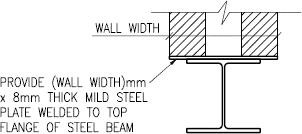
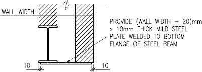
1. All Materials and workmanship to be in accordance with BS8110 parts 1 & 2 – The structural use of concrete
2. Concrete quality to be 35N/mm2 at 28 Days unless noted otherwise, Max aggrigate to be 20mm, Min Cement content 330kg/m3, max water to cement ratio 0.6
3. Reinforcement to be placed in accordance with BS8110
4. Concrete cubes to be taken at 7 & 28 Days to obtain required crushing strengths
5. Concrete quality for mass concrete foundations in non aggressive soils to be 25N/mm2
6. No reinforcement to be cut displaced or omitted without prior written agreement of the engineer.
7. Cover to reinforcement to be in accordance with BS8110 Part 1 tables 3.3 & 3.4
8. Ground Slab to be blinded into 50mm of lean mix prior to reinforcement being placed in position, blinding concrete mix to be 1/10 to all reinforcement bases except for water resisting structures.
9. If no soil investigation and been carried out then sulphate – resisting cement should be used within the ground.
10. For below ground structures provide waterproof concrete installed and detailed to specialist specifications.
Calc. by KP Date 03/07/2024
Chk'd By Date App'd Date
Timber:
1. All Materials and workmanship to be in accordance with BS5268: Part 2 - Structural Use of Timber
2. Roof Trusses and bracing to be designed and detailed by specialist subcontractor. Trusses to be designed and fabricated in accordance with BS5268: Parts 2 & 3
3. All timbers to have a minimum grade of C16 (unless noted otherwise) and to have maximum moisture content of 18%
4. Joists to have a minimum end bearing of 50mm
5. Ends of joists built into cavity walls should not project into the cavity, and should be painted with two coats of bituminous primer
6. Multiple timber members to be bolted together at 600c.c. with M12 Bolts and 50x50x3mm washers unless noted otherwise.
7. No notches, holes or rebates etc. to be cut in any member without the written consent of the engineer
8. All structural timber to be adequately protected against adverse weather conditions during stacking and after erection
9. All structural timber to be treated by vacuum pressure impregnation of organic or waterborne preservative, to a dry salt retention in accordance with the manufacturer’s recommendations. Type of treatment may be: - ‘Tanalith’, ‘Celcure’, ‘Promtim’, or other only with the prior approval of the Architect.
10. All fixings in the roof space are to be galvanised unless noted otherwise
11. Strutting Requirement
<2.5m non required
2.5m – 4.5m at mid-span
>4.5m at 1/3 span points
12. Where strutting is required provide solid strutting with a minimum thickness of 38mm and a depth no less than ¾ of the joist depth and strutting should be blocked solidly to perimeter walls
13. Strutting or blocking should not block the ventilation space in cold deck flat roofs
14. Restraint strapping - 100mm x 50mm wall plate strapped down to walls. Ceiling joists and rafters to be strapped to walls and gable walls, straps built into cavity, across at least 3 timbers with noggins. All straps to be 1000 x 30 x 5mm galvanized straps or other approved to BSEN 845-1 at 2m centres, in accordance with CP111 Part 2.
15. Where purlins are designed to support the rafters, rafters are to be birdsmouthed to the purlin.
16. Where supported by timber posts, the bearing should be the full width of any such supporting post. Where beams are to be seated on posts they are to be positioned centrally on the posts unless noted otherwise.
17. Where members are notched at the supports to a depth greater than 1/3 depth of the member the engineer is to be notified.
18. At the top and bottom of timber column / post positions a minimum of 2No horizontal restraint straps and noggins should be provided running orthogonally to the joist / rafter to provide restraint. These straps should be a minimum of 1200mm long x 30mm wide by 5mm thick in galvanised mild steel (or similar proprietary product). Straps will be suitably fixed to both the column and noggin.
19. For columns / posts directly adjacent to existing masonry, these should be resin anchored into the masonry using M12 HiltiHY70 anchors (or similar) @ 450mm vertical centres. Angle brackets may be used if preferred to direct fixing.
20. Where steelwork is to be installed in loft conversions ensure there is a 25mm gap between the top of the existing ceiling joist and the underside of the steel beam to avoid unintended load transfer.
21. Joints between members are to be created using either traditional joinery techniques or proprietary fixings. Where input is required contact the engineer.
22.Insulation and Ventilation requirements will not have been considered within this document when specifying joists/rafter sizes. The joist/rafter sizes mentioned might need to be increased in depth to allow for the relevant insulation/ventilation to be provided. Refer to architects details for minimum joist/rafter depth requirements for insulation/ventilation purposes.
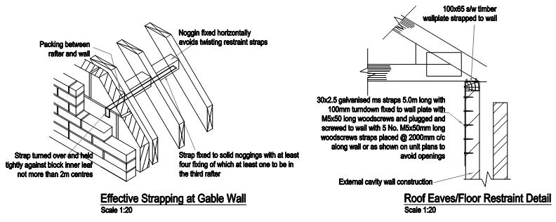
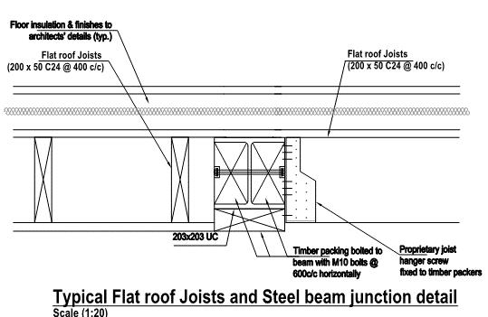
23. All Materials and workmanship to be in accordance with BS5628 Code of Practice for the Structural Use of Brickwork
24. Brickwork to have average crushing strength of 20.5N/mm2 unless noted otherwise
25. Blockwork belowground to be high density concrete blocks with a minimum compressive strength of 10N/mm2, above ground provide aerated lightweight blocks with a minimum compressive strength of 7.3N/mm2 unless nother otherwise
26. Mortar to be Class ii below ground and Class iii above ground unless noted otherwise.
27. ‘Hyload’ DPC or similar approved to all walls.
28. Wall ties to be stainless steel vertical twist type ties to comply with BS1243 at a maximum spacing of 900mm horzonatally and 450mm vertically with a minimum embedment of 50mm in the mortar joint unless noted otherwise. Where cavity width is >90mm ties to be placed 450mm vertically and horizontally. Additional ties to be provided at the sides of all openings so that there is at least one tie at 300mm c/c maximum
29. Wall ties shall not slop inwards
30. Brickwork restraints to be in accordance with BS5628 PT 1 at 1200mm c/c restraints to brickwork and 1200mm c/c for vertical straps.
31. Joints to masonry to be a minimum of 6m centres for blockwork and with a minimum distance of 3m from the end of any wall in accordance with BS5628 and a maximum of 12m centres for brickwork.
32. At brick/block junctions, brickwork is to be block bonded into blockwork unless noted otherwise.
33. Where blocks are laid flat they are to be solid concrete blocks.
34. Lintel Bearings to be in accordance with manufacturers recommendations.
35. Where existing masonry is deemed to be of poor quality, or where the mortar has degraded significantly, the brickwork should be either re- pointed or replaced in its entirety as appropriate prior to loading.
36. Unless noted otherwise all concrete blocks are to be bedded on narrow edge i.e. NOT laid flat.
37. Horizontal / Vertical restraint strapping to floors and roofs as indicated in the Building Regulations Part A "Lateral support by roofs and floors" [Diagrams 15 and 16] must be provided.
38. Ties movement joints should be provided at the following maximum centres; 6m centres in blockwork, 12m centres in brickwork. Joint locations should be as per the architects recommendations but our recommendation is that they are positioned adjacent to wind-posts, columns or buttressing walls, joint spacing should be reduced at positions of restraint i.e. cranks & corners. If joint centres cannot be achieved then we recommend that bed joint reinforcement is used at 450mm vertical centres.
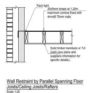
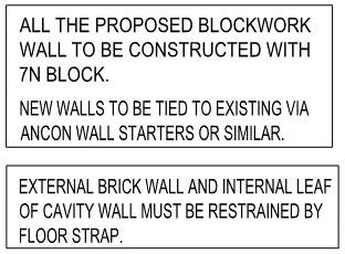
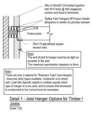
Section:
Calc. by KP Date 03/07/2024
Chk'd By Date App'd Date
1. Where steel beams bear directly onto masonry (i.e. no padstones) they are to be bedded onto a dry / level mortar bed. Unless noted otherwise all concrete blocks are to be bedded on narrow edge i.e. NOT laid flat.
2. In many instances historic buildings, particularly in the south east, will have poor quality masonry and degrading mortar capable of sustaining only a limited amount of compressive force. In such cases the engineer should be notified as the padstone sizes specified may need to be increased in size.
3. All padstones specified are to be C35 concrete. Where it is not possible to find "off the shelf" padstone sizes it may be necessary to cast in- situ padstones, or to cut/stack lintels to give the correct padstone dimension requirements. Lintels can be stacked as shown below, if a padstone with significant depth is required (example below shows two 800mm long 140x100 pre-cast concrete lintels stacked on top of eachother to create an 800x100x300 padstone). Lintels can be stacked to achieve the required depth, but must not be positioned side-by-side in any circumstances.
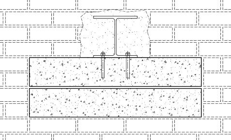
4. Mild steel spreader plates may be used as an alternative to padstones providing the following detail, with stiffeners to prevent the bearing plates from bending, is applied:
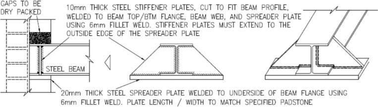
5. Where beams are oriented in the same direction of the padstone (i.e. parrallel), then mild steel shims must be used, as per the detail below, to ensure even pressure distribution on the padstone.
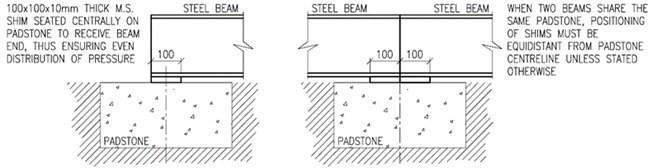
Padstone specifications are called-up thus: 440 x 100 x 215 (LENGTH) (WIDTH) (HEIGHT)
6. If the padstone width is referred to as "(wall width)" this means that the padstone width is to be equal to the full supporting wall width, including the cavity where appropriate. In no case should the padstone width be less than 200mm.
7. Padstones should in no case be wider than the wall (or single leaf of a cavity wall) upon which they are supported. If the supporting wall width is found to be less than the width of the specified padstone the engineer should be notified immediately.
8. Where two beams share the same padstone they are to be arranged symmetrically on the padstone, so that (unless noted otherwise) neither padstone is offset from the centre of the padstone more or less than the other.
Pitch 45 ° Tile type : Concrete Tiles (assumed)
(a) ROOF DEAD LOAD
Clay Tiles (Plain - Machine Made 101.6 mm gauge)
Clay Tiles (Single Lap Interlocking)
Concrete Tiles (Plain - Stone Aggregate 101.6 mm gauge)
Concrete Tiles (Single Lap Interlocking)
Slates (Including 76.2 mm Lap + Nails)
Membrane + Insulation
Boarding (Battenboard, blockboard, laminboard)
Battens + Felt
(b) FLAT ROOF DEAD LOAD
Finish (2 Layers, 19.1mm)
Felt (3 Layer)
Boarding (Battenboard, blockboard, laminboard)
+ Skim (12.7mm)
Joists + Insulation
(c) CEILING DEAD LOAD
(e) ROOF AND CEILING IMPOSED LOADS
Applicabel In Plan
(a) WALLS LOADINGS (100mm Inner Leaf)
(b) EXTERNAL CAVITY WALLS (100mm Inner Leaf)
(c) PARTY WALLS (per leaf) (100mm cavity)
(d) INTERNAL LOADBEARING MASONRY WALLS
(e) TIMBER WALLS
e.1 Timber stud - Dormer Cheek - (1.0 Hr Fire Resistance)
e.2 Internal timber stud partition- (1.0 Hr Fire Resistance)
(b) UPPER FLOORS : DEAD LOADS (HOUSES)
(c) UPPER FLOORS : IMPOSED LOADS
(d) GROUND FLOOR : DEAD LOADS
(d) GROUND FLOOR : DEAD LOADS
DEAD LOAD
(a) FLIGHTS (Timber)
with Risers and 12.5mm plasterboard
(b) IMPOSED LOADS (Hosues)
(c) FLIGHTS (Precast Concrete)
(d) LANDINGS/LOBBY AREAS (Precast Concrete)
(e) IMPOSED LOADS (Apartments)
Your name goes here Your address goes here
Site: 51 West End Avenue, Pinner, HA5 1BN
Job:
Job number:
Project started 25 Jun 2024 byKP
Site address: 51 West End Avenue, Pinner, HA5 1BN
Client: DESIGNLABS LONDON
ITEMS:
1: Beam: TRJ-1 (Rafters)
Span: 3.6 m.
Reactions (unfactored/factored): R1: 1.37/1.91 kN R2: 1.37/1.91 kN
Use 50 x 200 C24
2: Beam: TB-01 (Slopping rafter)
Span: 3.6 m.
Reactions (unfactored/factored): R1: 7.86/11.02 kN R2: 5.92/8.41 kN
Use 3no 50 x 200 C24
3: Beam: TB-01 (Not to use in print)
Span: 2.3 m.
Reactions (unfactored/factored): R1: 4.82/6.81 kN R2: 4.67/6.62 kN
4: Beam: HB-01
Span: 3.3 m.
Reactions (unfactored/factored): R1: 6.51/9.14 kN R2: 9.14/12.82 kN
Use 3no 50 x 250 C24
5: Beam: HB-02
Span: 5.0 m.
Made byKP
Page 1
File copy
Steel.eubPrinted 19 Jul 2024 09:25
Reactions (unfactored/factored): R1: 14.68/20.56 kN R2: 16.97/23.77 kN
Use 2no 50 x 250 C24 + 20 x 240 flitch plate
6: Beam: HB-02A
Span: 3.2 m.
Reactions (unfactored/factored): R1: 2.23/3.12 kN R2: 4.46/6.23 kN
Use 2no 50 x 250 C24 + 20 x 240 flitch plate
7: Beam: VB-01
Span: 5.4 m.
Reactions (unfactored/factored): R1: 9.23/12.90 kN R2: 5.13/7.17 kN
Use 2no 50 x 250 C24 + 20 x 240 flitch plate
8: Beam: VB-01A
Span: 3.2 m.
Reactions (unfactored/factored): R1: 3.04/4.25 kN R2: 1.52/2.12 kN
Use 3no 50 x 200 C24
9: Beam: RB-01
Span: 1.8 m.
Reactions (unfactored/factored): R1: 1.85/2.59 kN R2: 1.57/2.19 kN
Use 2no 50 x 200 C24
10: Beam: VB-02
Span: 2.2 m. + 1.85 m. RH cantilever
Reactions (unfactored/factored): R1: -5.81/-2.35 kN R2: 20.25/28.37 kN
Use 2no 50 x 250 C24 + 20 x 240 flitch plate
Your name goes here Your address goes here
Site: 51 West End Avenue, Pinner, HA5 1BN
Job:
Job number:
11: Beam: HB-03
Span: 2.0 m. + 1.50 m. RH cantilever
Reactions (unfactored/factored): R1: -0.50/0.29 kN R2: 5.02/7.01 kN
Use 3no 50 x 200 C24
12: Beam: RB-02
Span: 3.55 m.
Made byKP
Page 2
File copy
Steel.eub Printed 19 Jul 2024 09:25
Reactions (unfactored/factored): R1: 19.15/26.89 kN R2: 20.61/28.91 kN
Use 2no 50 x 250 C24 + 20 x 240 flitch plate
13: Beam: Existng ValleyBeam
Span: 5.7 m.
Reactions (unfactored/factored): R1: 5.41/7.57 kN R2: 10.83/15.13 kN
Use 2no 50 x 250 C24 + 10 x 240 flitch plate
14 Timber post/stud: TP-1
Use 100 x 100 C24
15 Timber post/stud: TP-2
Use 100 x 100 C24
16 Timber post/stud: TP-4
Use 100 x 100 C24
17 Timber post/stud: TP-5
Use 100 x 100 C24
18 Timber post/stud: TP-6
Use 100 x 100 C24
19 Timber post/stud: TP-3
Use 100 x 100 C24
20: Column: SP-3
Section: 100 x 100 x 10.0 SHS Grade S355
Sum of stress ratios = 0.137 OK
21: Beam: Existing Floor joists over Bedroom-1 Span: 3.6 m.
Reactions (unfactored/factored): R1: 2.08/2.96 kN R2: 1.67/2.40 kN
Use 50 x 200 C24
22: Beam: Propsoed newLoft floor joists
Span: 2.75 m.
Reactions (unfactored/factored): R1: 2.17/3.09 kN R2: 2.53/3.59 kN
Use 50 x 200 C24
23: Beam: TB-02
Span: 2.9 m.
Reactions (unfactored/factored): R1: 6.67/9.38 kN R2: 3.18/4.50 kN
Use 3no 50 x 200 C24
Your name goes here Your address goes here
Site: 51 West End Avenue, Pinner, HA5 1BN
Job:
Made byKP
Page 3
Job number: File copy
Steel.eub Printed 19 Jul 2024 09:25
24: Beam: TB-03
Span: 1.9 m.
Reactions (unfactored/factored): R1: 3.30/4.61 kN R2: 3.30/4.61 kN
Use 2no 50 x 200 C24
25: Beam: TB-04
Span: 2.9 m.
Reactions (unfactored/factored): R1: 4.31/6.03 kN R2: 5.53/7.73 kN
Use 2no 50 x 200 C24
26: Beam: TB-05
Span: 3.65 m.
Reactions (unfactored/factored): R1: 9.49/13.32 kN R2: 19.26/26.92 kN
Use 2no 50 x 200 C24 + 10 x 190 flitch plate
27: Beam: TB-07
Span: 2.75 m.
Reactions (unfactored/factored): R1: 5.73/8.16 kN R2: 7.49/10.65 kN
Use 3no 50 x 200 C24
28: Beam: SB-05A
Span: 4.1 m.
Reactions (unfactored/factored): R1: 10.01/14.00 kN R2: 29.32/41.07 kN
Use 203 x 102 x 23 UB S275
29: Beam: Existing beam check
Span: 5.3 m.
Reactions (unfactored/factored): R1: 42.15/60.04 kN R2: 32.75/46.86 kN
Use 203 x 203 x 46 UC S275
30: Beam: SB-1
Span: 5.2 m.
Reactions (unfactored/factored): R1: 50.02/70.62 kN R2: 35.05/49.69 kN
Use 203 x 203 x 46 UC S275
31: Beam: SB-2
Span: 3.75 m.
Reactions (unfactored/factored): R1: 14.41/20.12 kN R2: 17.52/24.68 kN
Use 203 x 203 x 46 UC S275
32: Beam: SB-3
Span: 3.75 m.
Reactions (unfactored/factored): R1: 34.01/47.76 kN R2: 25.43/35.78 kN
Use 203 x 203 x 46 UC S275
33: Beam: SB-4
Span: 4.3 m.
Reactions (unfactored/factored): R1: 73.86/104.72 kN R2: 61.62/87.02 kN
Use 203 x 203 x 60 UC S275
34: Beam: SB-5
Span: 4.6 m.
Reactions (unfactored/factored): R1: 34.93/49.06 kN R2: 50.49/71.13 kN
Use 203 x 203 x 60 UC S275
Your name goes here Your address goes here
Site: 51 West End Avenue, Pinner, HA5 1BN
Job:
Made byKP
Page 4
Job number: File copy
Steel.eub Printed 19 Jul 2024 09:25
35: Column: SP-1
Section: 100 x 100 x 10.0 SHS Grade S355
Sum of stress ratios = 0.285 OK
36: Column: SP-2
Net moments: My = 7.16 kNm Mz = 0.00kNm
Section: 100 x 100 x 10.0 SHS Grade S355
Sum of stress ratios = 0.254 OK
37: Beam: First floor joists
Span: 4.45 m.
Reactions (unfactored/factored): R1: 1.50/2.18 kN R2: 1.50/2.18 kN
Use 50 x 200 C24
38: Beam: First floor Flat roof joists
Span: 3.8 m.
Reactions (unfactored/factored): R1: 1.33/1.88 kN R2: 1.33/1.88 kN
Use 50 x 200 C24
39: Beam: SB-6
Span: 4.5 m.
Reactions (unfactored/factored): R1: 70.78/99.68 kN R2: 86.33/122.17 kN
Use 203 x 203 x 46 UC S275
40: Beam: SB-7
Span: 5.15 m.
Reactions (unfactored/factored): R1: 33.01/45.40 kN R2: 33.01/45.40 kN
Use 203 x 203 x 46 UC S275
41: Beam: SB-8
Span: 3.0 m.
Reactions (unfactored/factored): R1: 26.34/36.01 kN R2: 20.81/28.53 kN
Use 203 x 102 x 23 UB S275
42: Beam: SB-09
Span: 3.05 m.
Reactions (unfactored/factored): R1: 18.17/24.76 kN R2: 18.17/24.76 kN
Use 100 x 100 x 10.0 HF SHS S355
43: Column: SP-3
Net moments: My = 0.00 kNm Mz = 3.47kNm
Section: 80 x 80 x 8.0 SHS Grade S355
Sum of stress ratios = 0.309 OK
44: Beam: SB-10
Span: 3.0 m.
Reactions (unfactored/factored): R1: 8.42/11.59 kN R2: 8.42/11.59 kN
Use 100 x 100 x 10.0 HF SHS S355
45: Column: SP-4
Section: 100 x 100 x 10.0 SHS Grade S355
Sum of stress ratios = 0.014 OK
Your name goes here Your address goes here
Site: 51 West End Avenue, Pinner, HA5 1BN
Job:
Job number:
46: Beam: SB-11
Span: 8.1 m.
Made byKP
Page 5
File copy
Steel.eub Printed 19 Jul 2024 09:25
Reactions (unfactored/factored): R1: 53.71/75.50 kN R2: 109.40/152.34 kN
Use 254 x 254 x 167 UC S275
47: Column: SP-5
Section: 200 x 200 x 10.0 SHS Grade S355
Sum of stress ratios = 0.061 OK
48: Column: SP-5A
Section: 200 x 200 x 10.0 SHS Grade S355
Sum of stress ratios = 0.030 OK
49: Web cleat connection
Beam [Item 40]: 203x102x23 UB connects to web of beam [Item 41]: 203x203x46 UC
Factored load carried byconnection = 0.000 kN
Use 150mm long S275 angle cleats with 2 rows of M16 bolts at 75 c/s Connection design unsuitable
50: Web cleat connection
Beam [Item 33]: 203x102x23 UB connects to web of beam [Item 34]: 203x203x46 UC
Factored load carried byconnection = 0.000 kN
Use 150mm long S275 angle cleats with 2 rows of M16 bolts at 60 c/s Connection design unsuitable
51: Web cleat connection
Beam [Item 40]: 203x102x23 UB connects to web of beam [Item 41]: 203x203x46 UC
Factored load carried byconnection = 0.000 kN
Use 150mm long S275 angle cleats with 2 rows of M16 bolts at 75 c/s Connection design unsuitable
52: Beam: Rafters - !st floor level
Span: 3.1 m.
Reactions (unfactored/factored): R1: 1.18/1.65 kN R2: 1.18/1.65 kN
Use 50 x 150 C24
53: Beam: Typical WindowTrimmer
Span: 3.6 m.
Reactions (unfactored/factored): R1: 2.02/2.82 kN R2: 1.21/1.69 kN
Use 2no 50 x 150 C24
54: Beam: TB-09
Span: 4.2 m.
Reactions (unfactored/factored): R1: 1.18/1.62 kN R2: 1.29/1.85 kN
Use 2no 50 x 200 C24
55: Beam: TB-08
Span: 2.8 m.
Reactions (unfactored/factored): R1: 18.15/25.87 kN R2: 18.15/25.87 kN
Use 2no 50 x 200 C24 + 10 x 190 flitch plate
Your name goes here Your address goes here
Site: 51 West End Avenue, Pinner, HA5 1BN
Made byKP
Job: Page 6
Job number: File copy Steel.eub Printed 19 Jul 2024 09:25
Beam: TRJ-1 (Rafters)
Load types: U:UDL; Load positions are measured in m. from R1
Load durations: G: Dead; Qx: Imposed: QA: Residential
Maximum B.M. = 1.72 kNm (6.10) at 1.80 m. from R1
Maximum S.F. = -1.91 kN (6.10) at R2
Mid-span deflections: Dead: 1.14 x 10⁸/EI (E in N/mm2, I in cm4)
Live: 0.52 x 10⁸/EI
Total: 1.66 x 10⁸/EI
Timber beam calculation to BS EN1995-1-1 using C24 timber
Use 50 x 200 C24 4.2 kg/m approx
Wel,y = 333.3 cm3 Iy = 3,333 cm4 Depth factor, kh,y = 1.00 [EC5 eq.(3.1)]
Timber grade: C24
Grade bending strength, fm,k = 24.0 N/mm2 [BS EN 338: 2009 Table 1]
Grade shear strength, fv,k = 4.0 N/mm2 [BS EN 338: 2009 Table 1]
Material partial factor, gM = 1.3 [EC5 UK Table NA.3]
E0.05 = 7,400 N/mm2; E0,mean = 11,000 N/mm2 [BS EN 338: 2009 Table 1]
Loading modification factor, kmod = 0.7 (Service class 2; Live load duration: Long term) [EC5 Tables 2.2/3.1]
Load sharing factor, ksys = 1.1 [EC5 6.6(2)]
Deflection modification factor, kdef = 0.80 [EC5 Table 3.2]
Bending
Height factor, kh = 1.0 [EC5 3.2(3)]
Design bending strength, fm,y,d = fm,k.kmod.kh.ksys/gm = 24.0 x 0.70 x 1.00 x 1.1/1.30 = 14.22 N/mm2
Design bending stress, sm,y,d = 1.72 x 1000/333.3 = 5.16 N/mm2 OK
Bending resistance = 14.22 x 333.3/1000 = 4.74 kNm
Shear
Effective width for shear, bef = kcr.b = 0.67 x 50 = 33.5 mm. [A1:2008 (6.13a)]
Design shear strength, fv,d = fv,k.kmod.ksys/gm = 4.00 x 0.70 x 1.1/1.30 = 2.37 N/mm2
Design shear stress, sv,y,d = 1.91 x 1000 x (3/2)/(33.5 x 200) = 0.43 N/mm2 OK
Shear resistance = 2.37 x 33.5 x 200 x (2/3)/1000 = 10.6 kN
Deflection
Final deflection limit = L/250 = 14.40 mm
Instantaneous mid-span shear deflection = 1.2 x 1.23 x 106/((E/16) x 50 x 200) = 0.21 mm
Final shear deflection is assumed to increase in proportion to total bending deflection
Your name goes here Your address goes here
Site: 51 West End Avenue, Pinner, HA5 1BN
Made byKP
Job: Page 7
Job number: File copy
Steel.eub Printed 19 Jul 2024 09:25
Your name goes here Your address goes here
Site: 51 West End Avenue, Pinner, HA5 1BN
Made byKP
Job: Page 8
Job number: File copy Steel.eub Printed 19 Jul 2024 09:25
: TB-01 (Slopping rafter)
Load types: U:UDL; V:Variable load; Load positions are measured in m. from R1 Load durations: G: Dead; Qx: Imposed: QA: Residential
Maximum B.M. = 8.21 kNm (6.10) at 1.65 m. from R1
Maximum S.F. = 11.0 kN (6.10) at R1
Mid-span deflections: Dead: 4.59 x 10⁸/EI (E in N/mm2, I in cm4)
Live: 3.30 x 10⁸/EI
Total: 7.90 x 10⁸/EI
Timber beam calculation to BS EN1995-1-1 using C24 timber
Use 3no 50 x 200 C24 12.6 kg/m approx
Wel,y = 1,000 cm3 Iy = 10,000 cm4 Depth factor, kh,y = 1.00 [EC5 eq.(3.1)]
Timber grade: C24
Grade bending strength, fm,k = 24.0 N/mm2 [BS EN 338: 2009 Table 1]
Grade shear strength, fv,k = 4.0 N/mm2 [BS EN 338: 2009 Table 1]
Material partial factor, gM = 1.3 [EC5 UK Table NA.3]
E0.05 = 7,400 N/mm2; E0,mean = 11,000 N/mm2 [BS EN 338: 2009 Table 1]
Loading modification factor, kmod = 0.7 (Service class 2; Live load duration: Long term) [EC5 Tables 2.2/3.1]
Load sharing factor, ksys = 1.0
Deflection modification factor, kdef = 0.80 [EC5 Table 3.2]
Bending
Height factor, kh = 1.0 [EC5 3.2(3)]
Design bending strength, fm,y,d = fm,k.kmod.kh.ksys/gm = 24.0 x 0.70 x 1.00 x 1.0/1.30 = 12.92 N/mm2
Design bending stress, sm,y,d = 8.21 x 1000/1,000 = 8.21 N/mm2 OK
Bending resistance = 12.92 x 1,000/1000 = 12.9 kNm
Shear
Effective width for shear, bef = kcr.b = 0.67 x 150 = 100.5 mm. [A1:2008 (6.13a)]
Design shear strength, fv,d = fv,k.kmod.ksys/gm = 4.00 x 0.70 x 1.0/1.30 = 2.15 N/mm2
Design shear stress, sv,y,d = 11.0 x 1000 x (3/2)/(100.5 x 200) = 0.82 N/mm2 OK
Shear resistance = 2.15 x 100.5 x 200 x (2/3)/1000 = 28.9 kN
Deflection
Final deflection limit = L/250 = 14.40 mm
Instantaneous mid-span shear deflection = 1.2 x 5.77 x 106/((E/16) x 150 x 200) = 0.34 mm
Final shear deflection is assumed to increase in proportion to total bending deflection
Your name goes here Your address goes here
Site: 51 West End Avenue, Pinner, HA5 1BN
Made byKP
Job: Page 9
Job number: File copy
Steel.eub Printed 19 Jul 2024 09:25
Your name goes here Your address goes here
Site: 51 West End Avenue, Pinner, HA5 1BN Made byKP
Job:
Job number:
: TB-01 (Not to use in print)
10
Load types: U:UDL; V:Variable load; P:Point load; Load positions are measured in m. from R1 Load durations: G: Dead; Qx: Imposed: QA: Residential
Maximum B.M. = 4.58 kNm (6.10) at 1.25 m. from R1
Maximum S.F. = 6.81 kN (6.10) at R1
Mid-span deflections: Dead: 0.97 x 10⁸/EI (E in N/mm2, I in cm4) Live: 0.70 x 10⁸/EI
Total: 1.67 x 10⁸/EI
Your name goes here Your address goes here
Site: 51 West End Avenue, Pinner, HA5 1BN Made byKP
Job:
Job number:
: HB-01
Load types: V:Variable load; P:Point load; Load positions are measured in m. from R1
Load durations: G: Dead; Qx: Imposed: QA: Residential
Maximum B.M. = 11.9 kNm (6.10) at 1.80 m. from R1
Maximum S.F. = -12.8 kN (6.10) at R2
Mid-span deflections: Dead: 5.49 x 10⁸/EI (E in N/mm2, I in cm4)
Live: 3.17 x 10⁸/EI
Total: 8.66 x 10⁸/EI
Timber beam calculation to BS EN1995-1-1 using C24 timber
Use 3no 50 x 250 C24 15.8 kg/m approx
Wel,y = 1,563 cm3 Iy = 19,531 cm4 Depth factor, kh,y = 1.00 [EC5 eq.(3.1)]
Timber grade: C24
Grade bending strength, fm,k = 24.0 N/mm2 [BS EN 338: 2009 Table 1]
Grade shear strength, fv,k = 4.0 N/mm2 [BS EN 338: 2009 Table 1]
Material partial factor, gM = 1.3 [EC5 UK Table NA.3]
E0.05 = 7,400 N/mm2; E0,mean = 11,000 N/mm2 [BS EN 338: 2009 Table 1]
Loading modification factor, kmod = 0.7 (Service class 1; Live load duration: Long term) [EC5 Tables 2.2/3.1]
Load sharing factor, ksys = 1.0
Deflection modification factor, kdef = 0.60 [EC5 Table 3.2]
Bending
Height factor, kh = 1.0 [EC5 3.2(3)]
Design bending strength, fm,y,d = fm,k.kmod.kh.ksys/gm = 24.0 x 0.70 x 1.00 x 1.0/1.30 = 12.92 N/mm2
Design bending stress, sm,y,d = 11.89 x 1000/1,563 = 7.61 N/mm2 OK
Bending resistance = 12.92 x 1,563/1000 = 20.2 kNm
Shear
Effective width for shear, bef = kcr.b = 0.67 x 150 = 100.5 mm. [A1:2008 (6.13a)]
Design shear strength, fv,d = fv,k.kmod.ksys/gm = 4.00 x 0.70 x 1.0/1.30 = 2.15 N/mm2
Design shear stress, sv,y,d = 12.8 x 1000 x (3/2)/(100.5 x 250) = 0.77 N/mm2 OK
Shear resistance = 2.15 x 100.5 x 250 x (2/3)/1000 = 36.1 kN
Deflection
Final deflection limit = L/250 = 13.20 mm
Your name goes here Your address goes here
Site: 51 West End Avenue, Pinner, HA5 1BN
Job:
Made byKP
Page 12
Job number: File copy
Steel.eub Printed 19 Jul 2024 09:25
Instantaneous mid-span shear deflection = 1.2 x 8.12 x 106/((E/16) x 150 x 250) = 0.38 mm
Final shear deflection is assumed to increase in proportion to total bending deflection
Mid-span deflections: x 1e8/EI
Your name goes here Your address goes here
Site: 51 West End Avenue, Pinner, HA5 1BN
Load types: U:UDL; V:Variable load; P:Point load; Load positions are measured in m. from R1
Load durations: G: Dead; Qx: Imposed: QA: Residential
Maximum B.M. = 33.6 kNm (6.10) at 2.75 m. from R1
Maximum S.F. = -23.8 kN (6.10) at R2
Mid-span deflections: Dead: 38.9 x 10⁸/EI (E in N/mm2, I in cm4)
Live: 20.2 x 10⁸/EI
Total: 59.1 x 10⁸/EI
Timber beam calculation to BS EN1995-1-1 using C24 timber
Use 2no 50 x 250 C24 + 20 x 240 flitch plate 48.2 kg/m approx
Timber: Wel,y = 1,042 cm3 Iy = 13,021 cm4 Depth factor, kh,y = 1.00 [EC5 eq.(3.1)]
Flitch plate: Wel,y = 192.0 cm3 Iy = 2,304 cm4 EIsteel = 210,000 x 2,304 x 104 = 4,838 x 109 Nmm2
Timber grade: C24
Grade bending strength, fm,k = 24.0 N/mm2 [BS EN 338: 2009 Table 1]
Grade shear strength, fv,k = 4.0 N/mm2 [BS EN 338: 2009 Table 1]
Material partial factor, gM = 1.3 [EC5 UK Table NA.3]
E0.05 = 7,400 N/mm2; E0,mean = 11,000 N/mm2 [BS EN 338: 2009 Table 1]
Loading modification factor, kmod = 0.7 (Service class 1; Live load duration: Long term) [EC5 Tables 2.2/3.1]
Load sharing factor, ksys = 1.0
Deflection modification factor, kdef = 0.60 [EC5 Table 3.2]
Loading will be carried by the timber members and flitch plate in proportion to their EI values. Checks are made using the mean and minimum E-values for timber to produce worst case stresses on timber and steel members respectively. See TRADA guidance document GD9, 2008, for more information.
Calculate timber bending and shear enhancement factor (kfl)
Design strengths can be multiplied by1.04 if the flitch plate takes 0.2-0.8 of total load (using E0,mean) GD9 Eq.(5)
EItimber = 11,000 x 13,021 x 104 = 1,432 x 109 Nmm2: Ktimber = EItimber/EItotal = 1,432/(1,432 + 4,838) = 0.228
Ksteel = 1 - 0.228 = 0.772: kfl = 1.04
Calculate effect of bolt holes
M10 bolts, staggered alternatelyabove/below NA, centres offset 0 mm from NA: assume 11 mm holes
Bending stress factor for a single hole = (h2(h2 - h.d' + 2d'.y)) /(h4 - h3d' +h.d'3 + d'4 -12h.d'y2) GD9 Eq.(10)
h = member height; d' = hole diameter; y = offset centre of hole from member centre
Your name goes here Your address goes here
Site: 51 West End Avenue, Pinner, HA5 1BN
Job:
Job number:
Resulting factors: Timber: 1.0 Steel: 1.0
Timber bending
Height factor, kh = 1.0 [EC5 3.2(3)]
Design bending strength, fm,y,d = fm,k.kmod.ksys.khy.kfl/gm
fm,y,d = 24.0 x 0.70 x 1.0 x 1.00 x 1.04/1.30 = 13.44 N/mm2
Made byKP
Page 14
File copy
Steel.eub Printed 19 Jul 2024 09:25
Design bending stress, sm,y,d = 0.228 x 33.6 x 1.000 x 1000/1041.7 = 7.37 N/mm2 OK
Timber shear
Effective width for shear, bef = kcrb = 0.67 x 100 = 67.0 mm. [A1:2008 (6.13a)]
Design shear strength, fv,d = fv,k.kmod.ksys.kfl/gm = 4.00 x 0.70 x 1.0 x 1.04/1.30 = 2.24 N/mm2
Design shear stress, ta = 0.228 x 23.8 x 1000 x (3/2)/(67.0 x 250) = 0.49 N/mm2 OK
Shear resistance = 2.24 x 67.0 x 250 x (2/3)/(0.228 x 1000) = 109.5 kN
Bearings
Grade compressive strength perpendicular to grain, fc,90,d = fc,90,k.kmod.ksys.kfl/gm fc,90,d = 2.50 x 0.70 x 1.0 x 1.04/1.3 = 1.40 N/mm2
Minimum bearing lengths: R1: 20.6 x 1000/(1.40 x 100) = 191mm (subject to adequate support under bearing) R2: 23.8 x 1000/(1.40 x 100) = 221mm
Deflection
Calculate instantaneous and final deflections, uinst, ufin: ufin = S(1+ kdef y2)uinst
Instantaneous deflection
Timber carries 1,432/(1,432+4,838) = 0.228 of total load (as above)
Bending deflection = 0.228 x 59.1 x 108/(1,432 x 109/104) = 9.4 mm
Mid-span shear deflection = 0.228 x 1.2 x 23.5 x 106/(E/16) x 100 x 250 = 0.4 mm (0.040 of bending deflection)
Total deflection = 9.43 + 0.38 = 9.8 mm (0.0020 L) OK
Final deflection
Efin = Einst x uinst/ufin
Emean,fin = 11,000 x 59.12/86.11 = 7,552 N/mm2
Using Emean,fin, Timber EI = 7,552 x 13,021 x 104 = 983 x 109 Nmm2
Timber carries 983/(983+4,838) = 0.169 of total load
Final deflection = 0.169 x 1.040 x 86.11 x 108/(983 x 109/104) = 15.4 mm (0.0031 L) OK
Flitch plate bending
Emin,fin = 7,400 x 59.12/86.11 = 5,080 N/mm2; Timber EI = 5,080 x 13,021 x 104 = 661 x 109 Nmm2
Using Emin,fin for timber, flitch plate carries 4,838/(662 + 4,838) = 0.880 of total load
Per TRADA GD9, factor load by 1.1 to allow for slip and shear deflection in plate
Flitch plate fbc = 0.880 x 33.62 x 1.1 x 1.000 x 1000/192.0 = 169.4 N/mm2 OK
Moment capacityis limited bysteel plate: Moment capacity= 265 x 192.0/(1000 x 1.000 x 1.1 x 0.880) = 52.6 kNm (timber: 61.3 kNm)
Your name goes here Your address goes here
Site: 51 West End Avenue, Pinner, HA5 1BN
Job:
Job number:
Bolting:
Made byKP
Page 15
File copy
Steel.eub Printed 19 Jul 2024 09:25
Use M10 4.6 bolts. Bolt numbers are calculated assuming worst case load on flitch plate Embedment strength, load in direction of grain, fh,0,k = 0.082(1 - 0.01d)pk = 0.082 x (1 - 0.10) x 350 = 25.8 N/mm2 (8.32) k90 = 1.35 + 0.015d = 1.35 + 0.15 = 1.50 EC5 (8.30) softwood fh,1,k = embedment strength 90° to grain, fh,90,k = fh,0,k/k90 = 25.8/1.50 = 17.2 N/mm2 (8.31)
Bolt characteristic axial capacity, Fax,Rk = 3.fc,90,k.Awasher = 3 x 2.5 x 594/1000 = 4.45 kN (compression under washer governs) 8.5 Fax,Rk has been calculated using a washer diameter of 3d, d+2 hole
Characteristic bolt yield moment, My,Rk = 0.3.fu,k.d2.6 = 0.3 x 400 x 102.6 = 47,773 Nmm EC5 (8.30)
Bolt capacity, Fv,Rk (per plane) EC5 Eq.(8.11)
Eq.(8.11f) (timber bearing): Fv,Rk = fh,1,k.t1.d = 8.61 kN
Eq.(8.11g) (bolt bending): Fv,Rk = fh,1,k.t1.d( (2 + 4My,Rk/(fh,1,k.d.t1 2)) -1) + Fax,Rk/4* = 5.96 kN <<<
Eq.(8.11h) (bolt yielding): Fv,Rk = 2.3 (My,Rk.fh,1,k.d) + Fax,Rk/4* = 7.71 kN
* Rope effect: use (0.25 x Johansen load) [first term] if < Fax,Rk/4 EC5 8.2.2(2)
Bolt design load capacity(double shear), Fv,Rd = kmod.Fv,Rk/gm = 2 x 0.7 x 5.96/1.3 = 6.42 kN
Bearings: R1 (20.6kN): Required number of bolts = 0.880 x 20.6/(6.42) = 2.82 i.e. 3 bolts min. R2 (23.8kN): Required number of bolts = 0.880 x 23.8/(6.42) = 3.26 i.e. 4 bolts min. For load transference a minimum of 7 bolts are also required across the span
Recommended bolting pattern across span: Bolts spaced at lesser of 2.5h or 600mm (i.e. 600 mm c/s) , alternately set max 63 mm (h/4) above and below centre line of beam with additional centred bolt(s) at each significant point load position - see GD9 for further guidance
Your name goes here Your address goes here
Site: 51 West End Avenue, Pinner, HA5 1BN
Made byKP
Job: Page 16
Job number: File copy Steel.eub Printed 19 Jul 2024 09:25
: HB-02A
Load types: V:Variable load; Load positions are measured in m. from R1
Load durations: G: Dead; Qx: Imposed: QA: Residential
Maximum B.M. = 3.84 kNm (6.10) at 1.85 m. from R1
Maximum S.F. = -6.23 kN (6.10) at R2
Mid-span deflections: Dead: 1.95 x 10⁸/EI (E in N/mm2, I in cm4)
Live: 0.90 x 10⁸/EI
Total: 2.85 x 10⁸/EI
Timber beam calculation to BS EN1995-1-1 using C24 timber
Use 2no 50 x 250 C24 + 20 x 240 flitch plate 48.2 kg/m approx
Timber: Wel,y = 1,042 cm3 Iy = 13,021 cm4 Depth factor, kh,y = 1.00 [EC5 eq.(3.1)]
Flitch plate: Wel,y = 192.0 cm3 Iy = 2,304 cm4 EIsteel = 210,000 x 2,304 x 104 = 4,838 x 109 Nmm2
Timber grade: C24
Grade bending strength, fm,k = 24.0 N/mm2 [BS EN 338: 2009 Table 1]
Grade shear strength, fv,k = 4.0 N/mm2 [BS EN 338: 2009 Table 1]
Material partial factor, gM = 1.3 [EC5 UK Table NA.3]
E0.05 = 7,400 N/mm2; E0,mean = 11,000 N/mm2 [BS EN 338: 2009 Table 1]
Loading modification factor, kmod = 0.7 (Service class 1; Live load duration: Long term) [EC5 Tables 2.2/3.1]
Load sharing factor, ksys = 1.0
Deflection modification factor, kdef = 0.60 [EC5 Table 3.2]
Loading will be carried by the timber members and flitch plate in proportion to their EI values. Checks are made using the mean and minimum E-values for timber to produce worst case stresses on timber and steel members respectively. See TRADA guidance document GD9, 2008, for more information.
Calculate timber bending and shear enhancement factor (kfl)
Design strengths can be multiplied by1.04 if the flitch plate takes 0.2-0.8 of total load (using E0,mean) GD9 Eq.(5)
EItimber = 11,000 x 13,021 x 104 = 1,432 x 109 Nmm2: Ktimber = EItimber/EItotal = 1,432/(1,432 + 4,838) = 0.228
Ksteel = 1 - 0.228 = 0.772: kfl = 1.04
Calculate effect of bolt holes
M10 bolts, staggered alternatelyabove/below NA, centres offset 0 mm from NA: assume 11 mm holes
Bending stress factor for a single hole = (h2(h2 - h.d' + 2d'.y)) /(h4 - h3d' +h.d'3 + d'4 -12h.d'y2) GD9 Eq.(10) h = member height; d' = hole diameter; y = offset centre of hole from member centre
Resulting factors: Timber: 1.0 Steel: 1.0
Timber bending
Height factor, kh = 1.0 [EC5 3.2(3)]
Design bending strength, fm,y,d = fm,k.kmod.ksys.khy.kfl/gm
fm,y,d = 24.0 x 0.70 x 1.0 x 1.00 x 1.04/1.30 = 13.44 N/mm2
Design bending stress, sm,y,d = 0.228 x 3.84 x 1.000 x 1000/1041.7 = 0.84 N/mm
Your name goes here Your address goes here
Site: 51 West End Avenue, Pinner, HA5 1BN
Job:
Job number:
Timber shear
Effective width for shear, bef = kcrb = 0.67 x 100 = 67.0 mm. [A1:2008 (6.13a)]
Made byKP
Page 17
File copy
Steel.eub Printed 19 Jul 2024 09:25
Design shear strength, fv,d = fv,k.kmod.ksys.kfl/gm = 4.00 x 0.70 x 1.0 x 1.04/1.30 = 2.24 N/mm2
Design shear stress, ta = 0.228 x 6.23 x 1000 x (3/2)/(67.0 x 250) = 0.13 N/mm2 OK
Shear resistance = 2.24 x 67.0 x 250 x (2/3)/(0.228 x 1000) = 109.5 kN
Bearings
Grade compressive strength perpendicular to grain, fc,90,d = fc,90,k.kmod.ksys.kfl/gm fc,90,d = 2.50 x 0.70 x 1.0 x 1.04/1.3 = 1.40 N/mm2
Minimum bearing lengths: R1: 3.12 x 1000/(1.40 x 100) = 29mm (subject to adequate support under bearing) R2: 6.23 x 1000/(1.40 x 100) = 58mm
Deflection
Calculate instantaneous and final deflections, uinst, ufin: ufin = S(1+ kdef.y2)uinst
Instantaneous deflection
Timber carries 1,432/(1,432+4,838) = 0.228 of total load (as above)
Bending deflection = 0.228 x 2.85 x 108/(1,432 x 109/104) = 0.5 mm
Mid-span shear deflection = 0.228 x 1.2 x 2.68 x 106/(E/16) x 100 x 250 = 0.0 mm (0.094 of bending deflection)
Total deflection = 0.46 + 0.04 = 0.5 mm (0.0002 L) OK
Final deflection
Efin = Einst x uinst/ufin
Emean,fin = 11,000 x 2.85/4.19 = 7,496 N/mm2
Using Emean,fin, Timber EI = 7,496 x 13,021 x 104 = 976 x 109 Nmm2
Timber carries 976/(976+4,838) = 0.168 of total load
Final deflection = 0.168 x 1.094 x 4.19 x 108/(976 x 109/104) = 0.8 mm (0.0002 L) OK
Flitch plate bending
Emin,fin = 7,400 x 2.85/4.19 = 5,043 N/mm2; Timber EI = 5,043 x 13,021 x 104 = 657 x 109 Nmm2
Using Emin,fin for timber, flitch plate carries 4,838/(657 + 4,838) = 0.881 of total load
Per TRADA GD9, factor load by 1.1 to allow for slip and shear deflection in plate
Flitch plate fbc = 0.881 x 3.84 x 1.1 x 1.000 x 1000/192.0 = 19.4 N/mm2 OK
Moment capacityis limited bysteel plate: Moment capacity= 265 x 192.0/(1000 x 1.000 x 1.1 x 0.881) = 52.5 kNm (timber: 61.3 kNm)
Bolting:
Use M10 4.6 bolts. Bolt numbers are calculated assuming worst case load on flitch plate
Embedment strength, load in direction of grain, fh,0,k = 0.082(1 - 0.01d)pk = 0.082 x (1 - 0.10) x 350 = 25.8 N/mm2 (8.32) k90 = 1.35 + 0.015d = 1.35 + 0.15 = 1.50 EC5 (8.30) softwood fh,1,k = embedment strength 90° to grain, fh,90,k = fh,0,k/k90 = 25.8/1.50 = 17.2 N/mm2 (8.31)
Bolt characteristic axial capacity, Fax,Rk = 3.fc,90,k.Awasher = 3 x 2.5 x 594/1000 = 4.45 kN (compression under washer governs) 8.5 Fax,Rk has been calculated using a washer diameter of 3d, d+2 hole
Characteristic bolt yield moment, My,Rk = 0.3.fu,k.d2.6 = 0.3 x 400 x 102.6 = 47,773 Nmm EC5 (8.30)
Bolt capacity, Fv,Rk (per plane) EC5 Eq.(8.11)
Eq.(8.11f) (timber bearing): Fv,Rk = fh,1,k.t1.d = 8.61 kN
Eq.(8.11g) (bolt bending): Fv,Rk = fh,1,k.t1.d( (2 + 4My,Rk/(fh,1,k.d.t1 2)) -1) + Fax,Rk/4* = 5.96 kN <<<
Eq.(8.11h) (bolt yielding): Fv,Rk = 2.3 (My,Rk.fh,1,k.d) + Fax,Rk/4* = 7.71 kN
Your name goes here Your address goes here
Site: 51 West End Avenue, Pinner, HA5 1BN
Job:
Job number:
* Rope effect: use (0.25 x Johansen load) [first term] if < Fax,Rk/4 EC5 8.2.2(2)
Made byKP
Page 18
File copy
Steel.eub Printed 19 Jul 2024 09:25
Bolt design load capacity(double shear), Fv,Rd = kmod.Fv,Rk/gm = 2 x 0.7 x 5.96/1.3 = 6.42 kN
Bearings: R1 (3.12kN): Required number of bolts = 0.881 x 3.12/(6.42) = 0.43 i.e. 1 bolt min.
R2 (6.23kN): Required number of bolts = 0.881 x 6.23/(6.42) = 0.85 i.e. 1 bolt min.
For load transference a minimum of 2 bolts are also required across the span
Recommended bolting pattern across span: Bolts spaced at lesser of 2.5h or 600mm (i.e. 600 mm c/s) , alternately set max 63 mm (h/4) above and below centre line of beam with additional centred bolt(s) at each significant point load position - see GD9 for further guidance
Your name goes here Your address goes here
Site: 51 West End Avenue, Pinner, HA5 1BN
Made byKP
Job: Page 19
Job number: File copy Steel.eub Printed 19 Jul 2024 09:25 Beam: VB-01
Load types: V:Variable load; Load positions are measured in m. from R1
Load durations: G: Dead; Qx: Imposed: QA: Residential
Maximum B.M. = 13.8 kNm (6.10) at 2.34 m. from R1
Maximum S.F. = 12.9 kN (6.10) at R1
Mid-span deflections: Dead: 20.1 x 10⁸/EI (E in N/mm2, I in cm4)
Live: 9.3 x 10⁸/EI
Total: 29.4 x 10⁸/EI
Timber beam calculation to BS EN1995-1-1 using C24 timber
Use 2no 50 x 250 C24 + 20 x 240 flitch plate 48.2 kg/m approx
Timber: Wel,y = 1,042 cm3 Iy = 13,021 cm4 Depth factor, kh,y = 1.00 [EC5 eq.(3.1)]
Flitch plate: Wel,y = 192.0 cm3 Iy = 2,304 cm4 EIsteel = 210,000 x 2,304 x 104 = 4,838 x 109 Nmm2
Timber grade: C24
Grade bending strength, fm,k = 24.0 N/mm2 [BS EN 338: 2009 Table 1]
Grade shear strength, fv,k = 4.0 N/mm2 [BS EN 338: 2009 Table 1]
Material partial factor, gM = 1.3 [EC5 UK Table NA.3]
E0.05 = 7,400 N/mm2; E0,mean = 11,000 N/mm2 [BS EN 338: 2009 Table 1]
Loading modification factor, kmod = 0.7 (Service class 1; Live load duration: Long term) [EC5 Tables 2.2/3.1]
Load sharing factor, ksys = 1.0
Deflection modification factor, kdef = 0.60 [EC5 Table 3.2]
Loading will be carried by the timber members and flitch plate in proportion to their EI values. Checks are made using the mean and minimum E-values for timber to produce worst case stresses on timber and steel members respectively. See TRADA guidance document GD9, 2008, for more information.
Calculate timber bending and shear enhancement factor (kfl)
Design strengths can be multiplied by1.04 if the flitch plate takes 0.2-0.8 of total load (using E0,mean) GD9 Eq.(5)
EItimber = 11,000 x 13,021 x 104 = 1,432 x 109 Nmm2: Ktimber = EItimber/EItotal = 1,432/(1,432 + 4,838) = 0.228 Ksteel = 1 - 0.228 = 0.772: kfl = 1.04
Calculate effect of bolt holes
M10 bolts, staggered alternatelyabove/below NA, centres offset 0 mm from NA: assume 11 mm holes
Bending stress factor for a single hole = (h2(h2 - h.d' + 2d'.y)) /(h4 - h3d' +h.d'3 + d'4 -12h.d'y2) GD9 Eq.(10) h = member height; d' = hole diameter; y = offset centre of hole from member centre
Resulting factors: Timber: 1.0 Steel: 1.0
Timber bending
Height factor, kh = 1.0 [EC5 3.2(3)]
Design bending strength, fm,y,d = fm,k.kmod.ksys.khy.kfl/gm
fm,y,d = 24.0 x 0.70 x 1.0 x 1.00 x 1.04/1.30 = 13.44 N/mm2
Design bending stress, sm,y,d = 0.228 x 13.8 x 1.000 x 1000/1041.7 = 3.03 N/mm2 OK
Your name goes here Your address goes here
Site: 51 West End Avenue, Pinner, HA5 1BN
Job:
Job number:
Timber shear
Effective width for shear, bef = kcrb = 0.67 x 100 = 67.0 mm. [A1:2008 (6.13a)]
Made byKP
Page 20
File copy
Steel.eub Printed 19 Jul 2024 09:25
Design shear strength, fv,d = fv,k.kmod.ksys.kfl/gm = 4.00 x 0.70 x 1.0 x 1.04/1.30 = 2.24 N/mm2
Design shear stress, ta = 0.228 x 12.9 x 1000 x (3/2)/(67.0 x 250) = 0.26 N/mm2 OK
Shear resistance = 2.24 x 67.0 x 250 x (2/3)/(0.228 x 1000) = 109.5 kN
Bearings
Grade compressive strength perpendicular to grain, fc,90,d = fc,90,k.kmod.ksys.kfl/gm fc,90,d = 2.50 x 0.70 x 1.0 x 1.04/1.3 = 1.40 N/mm2
Minimum bearing lengths: R1: 12.9 x 1000/(1.40 x 100) = 120mm (subject to adequate support under bearing) R2: 7.17 x 1000/(1.40 x 100) = 67mm
Deflection
Calculate instantaneous and final deflections, uinst, ufin: ufin = S(1+ kdef.y2)uinst
Instantaneous deflection
Timber carries 1,432/(1,432+4,838) = 0.228 of total load (as above)
Bending deflection = 0.228 x 29.4 x 108/(1,432 x 109/104) = 4.7 mm
Mid-span shear deflection = 0.228 x 1.2 x 9.70 x 106/(E/16) x 100 x 250 = 0.2 mm (0.033 of bending deflection)
Total deflection = 4.70 + 0.15 = 4.9 mm (0.0009 L) OK
Final deflection
Efin = Einst x uinst/ufin
Emean,fin = 11,000 x 29.45/43.21 = 7,496 N/mm2
Using Emean,fin, Timber EI = 7,496 x 13,021 x 104 = 976 x 109 Nmm2
Timber carries 976/(976+4,838) = 0.168 of total load
Final deflection = 0.168 x 1.033 x 43.21 x 108/(976 x 109/104) = 7.7 mm (0.0014 L) OK
Flitch plate bending
Emin,fin = 7,400 x 29.45/43.21 = 5,043 N/mm2; Timber EI = 5,043 x 13,021 x 104 = 657 x 109 Nmm2
Using Emin,fin for timber, flitch plate carries 4,838/(657 + 4,838) = 0.881 of total load
Per TRADA GD9, factor load by 1.1 to allow for slip and shear deflection in plate
Flitch plate fbc = 0.881 x 13.81 x 1.1 x 1.000 x 1000/192.0 = 69.7 N/mm2 OK
Moment capacityis limited bysteel plate: Moment capacity= 265 x 192.0/(1000 x 1.000 x 1.1 x 0.881) = 52.5 kNm (timber: 61.3 kNm)
Bolting:
Use M10 4.6 bolts. Bolt numbers are calculated assuming worst case load on flitch plate
Embedment strength, load in direction of grain, fh,0,k = 0.082(1 - 0.01d)pk = 0.082 x (1 - 0.10) x 350 = 25.8 N/mm2 (8.32) k90 = 1.35 + 0.015d = 1.35 + 0.15 = 1.50 EC5 (8.30) softwood fh,1,k = embedment strength 90° to grain, fh,90,k = fh,0,k/k90 = 25.8/1.50 = 17.2 N/mm2 (8.31)
Bolt characteristic axial capacity, Fax,Rk = 3.fc,90,k.Awasher = 3 x 2.5 x 594/1000 = 4.45 kN (compression under washer governs) 8.5 Fax,Rk has been calculated using a washer diameter of 3d, d+2 hole
Characteristic bolt yield moment, My,Rk = 0.3.fu,k.d2.6 = 0.3 x 400 x 102.6 = 47,773 Nmm EC5 (8.30)
Bolt capacity, Fv,Rk (per plane) EC5 Eq.(8.11)
Eq.(8.11f) (timber bearing): Fv,Rk = fh,1,k.t1.d = 8.61 kN
Eq.(8.11g) (bolt bending): Fv,Rk = fh,1,k.t1.d( (2 + 4My,Rk/(fh,1,k.d.t1 2)) -1) + Fax,Rk/4* = 5.96 kN <<<
Eq.(8.11h) (bolt yielding): Fv,Rk = 2.3 (My,Rk.fh,1,k.d) + Fax,Rk/4* = 7.71 kN
Your name goes here Your address goes here
Site: 51 West End Avenue, Pinner, HA5 1BN
Job:
Job number:
* Rope effect: use (0.25 x Johansen load) [first term] if < Fax,Rk/4 EC5 8.2.2(2)
Made byKP
Page 21
File copy
Steel.eub Printed 19 Jul 2024 09:25
Bolt design load capacity(double shear), Fv,Rd = kmod.Fv,Rk/gm = 2 x 0.7 x 5.96/1.3 = 6.42 kN
Bearings: R1 (12.9kN): Required number of bolts = 0.881 x 12.9/(6.42) = 1.77 i.e. 2 bolts min.
R2 (7.17kN): Required number of bolts = 0.881 x 7.17/(6.42) = 0.98 i.e. 1 bolt min.
For load transference a minimum of 3 bolts are also required across the span
Recommended bolting pattern across span: Bolts spaced at lesser of 2.5h or 600mm (i.e. 600 mm c/s) , alternately set max 63 mm (h/4) above and below centre line of beam with additional centred bolt(s) at each significant point load position - see GD9 for further guidance
Your name goes here Your address goes here
Site: 51 West End Avenue, Pinner, HA5 1BN
Made byKP
Job: Page 22
Job number: File copy Steel.eub Printed 19 Jul 2024 09:25 Beam: VB-01A
Load types: V:Variable load; Load positions are measured in m. from R1
Load durations: G: Dead; Qx: Imposed: QA: Residential
Maximum B.M. = 2.62 kNm (6.10) at 1.35 m. from R1
Maximum S.F. = 4.25 kN (6.10) at R1
Mid-span deflections: Dead: 1.33 x 10⁸/EI (E in N/mm2, I in cm4)
Live: 0.61 x 10⁸/EI
Total: 1.95 x 10⁸/EI
Timber beam calculation to BS EN1995-1-1 using C24 timber
Use 3no 50 x 200 C24 12.6 kg/m approx
Wel,y = 1,000 cm3 Iy = 10,000 cm4 Depth factor, kh,y = 1.00 [EC5 eq.(3.1)]
Timber grade: C24
Grade bending strength, fm,k = 24.0 N/mm2 [BS EN 338: 2009 Table 1]
Grade shear strength, fv,k = 4.0 N/mm2 [BS EN 338: 2009 Table 1]
Material partial factor, gM = 1.3 [EC5 UK Table NA.3]
E0.05 = 7,400 N/mm2; E0,mean = 11,000 N/mm2 [BS EN 338: 2009 Table 1]
Loading modification factor, kmod = 0.7 (Service class 2; Live load duration: Long term) [EC5 Tables 2.2/3.1]
Load sharing factor, ksys = 1.0
Deflection modification factor, kdef = 0.80 [EC5 Table 3.2]
Bending
Height factor, kh = 1.0 [EC5 3.2(3)]
Design bending strength, fm,y,d = fm,k.kmod.kh.ksys/gm = 24.0 x 0.70 x 1.00 x 1.0/1.30 = 12.92 N/mm2
Design bending stress, sm,y,d = 2.62 x 1000/1,000 = 2.62 N/mm2 OK
Bending resistance = 12.92 x 1,000/1000 = 12.9 kNm
Shear
Effective width for shear, bef = kcr.b = 0.67 x 150 = 100.5 mm. [A1:2008 (6.13a)]
Design shear strength, fv,d = fv,k.kmod.ksys/gm = 4.00 x 0.70 x 1.0/1.30 = 2.15 N/mm2
Design shear stress, sv,y,d = 4.25 x 1000 x (3/2)/(100.5 x 200) = 0.32 N/mm2 OK
Shear resistance = 2.15 x 100.5 x 200 x (2/3)/1000 = 28.9 kN
Deflection
Final deflection limit = L/250 = 12.80 mm
Instantaneous mid-span shear deflection = 1.2 x 1.82 x 106/((E/16) x 150 x 200) = 0.11 mm
Final shear deflection is assumed to increase in proportion to total bending deflection
Your name goes here Your address goes here
Site: 51 West End Avenue, Pinner, HA5 1BN
Made byKP
Job: Page 23
Job number: File copy
Steel.eub Printed 19 Jul 2024 09:25
Your name goes here Your address goes here
Site: 51 West End Avenue, Pinner, HA5 1BN
Made byKP
Job: Page 24
Job number: File copy Steel.eub Printed 19 Jul 2024 09:25
Beam: RB-01
Load types: V:Variable load; Load positions are measured in m. from R1
Load durations: G: Dead; Qx: Imposed: QA: Residential
Maximum B.M. = 1.08 kNm (6.10) at 0.86 m. from R1
Maximum S.F. = 2.59 kN (6.10) at R1
Mid-span deflections: Dead: 0.18 x 10⁸/EI (E in N/mm2, I in cm4)
Live: 0.08 x 10⁸/EI
Total: 0.26 x 10⁸/EI
Timber beam calculation to BS EN1995-1-1 using C24 timber
Use 2no 50 x 200 C24 8.4 kg/m approx
Wel,y = 666.7 cm3 Iy = 6,667 cm4 Depth factor, kh,y = 1.00 [EC5 eq.(3.1)]
Timber grade: C24
Grade bending strength, fm,k = 24.0 N/mm2 [BS EN 338: 2009 Table 1]
Grade shear strength, fv,k = 4.0 N/mm2 [BS EN 338: 2009 Table 1]
Material partial factor, gM = 1.3 [EC5 UK Table NA.3]
E0.05 = 7,400 N/mm2; E0,mean = 11,000 N/mm2 [BS EN 338: 2009 Table 1]
Loading modification factor, kmod = 0.7 (Service class 2; Live load duration: Long term) [EC5 Tables 2.2/3.1]
Load sharing factor, ksys = 1.0
Deflection modification factor, kdef = 0.80 [EC5 Table 3.2]
Bending
Height factor, kh = 1.0 [EC5 3.2(3)]
Design bending strength, fm,y,d = fm,k.kmod.kh.ksys/gm = 24.0 x 0.70 x 1.00 x 1.0/1.30 = 12.92 N/mm2
Design bending stress, sm,y,d = 1.08 x 1000/666.7 = 1.62 N/mm2 OK
Bending resistance = 12.92 x 666.7/1000 = 8.62 kNm
Shear
Effective width for shear, bef = kcr.b = 0.67 x 100 = 67.0 mm. [A1:2008 (6.13a)]
Design shear strength, fv,d = fv,k.kmod.ksys/gm = 4.00 x 0.70 x 1.0/1.30 = 2.15 N/mm2
Design shear stress, sv,y,d = 2.59 x 1000 x (3/2)/(67.0 x 200) = 0.29 N/mm2 OK
Shear resistance = 2.15 x 67.0 x 200 x (2/3)/1000 = 19.2 kN
Deflection
Final deflection limit = L/250 = 7.20 mm
Instantaneous mid-span shear deflection = 1.2 x 0.769 x 106/((E/16) x 100 x 200) = 0.07 mm
Final shear deflection is assumed to increase in proportion to total bending deflection
Your name goes here Your address goes here
Site: 51 West End Avenue, Pinner, HA5 1BN
Job:
Made byKP
Page 25
Job number: File copy
Steel.eub Printed 19 Jul 2024 09:25
Your name goes here Your address goes here
Site: 51 West End Avenue, Pinner, HA5 1BN
Made byKP
Job: Page 26
Job number: File copy Steel.eub Printed 19 Jul 2024 09:25
: VB-02
Span:
Load types: V:Variable load; P:Point load; Load positions are measured in m. from R1
Load durations: G: Dead; Qx: Imposed: QA: Residential
Maximum B.M. = -20.0 kNm at R2 (6.10)
Maximum S.F. = -6.44 kN at R2 (6.10)
Mid-span deflections: Dead = -3.10 x 10⁸/EI (E in N/mm2, I in cm4)
Live = 0.13 x 10⁸/EI (Live loads on span only)
Total = -2.98 x 10⁸/EI
RH cantilever:
Maximum B.M. = -23.9 kNm (6.10)
Maximum S.F. = 16.1 kN (6.10)
End deflections: Dead = 26.56 x 10⁸/EI (E in N/mm2, I in cm4)
Live = 14.41 x 10⁸/EI
Total = 40.97 x 10⁸/EI
Timber beam calculation to BS EN1995-1-1 using C24 timber
Use 2no 50 x 250 C24 + 20 x 240 flitch plate 48.2 kg/m approx
Timber: Wel,y = 1,042 cm3 Iy = 13,021 cm4 Depth factor, kh,y = 1.00 [EC5 eq.(3.1)]
Flitch plate: Wel,y = 192.0 cm3 Iy = 2,304 cm4 EIsteel = 210,000 x 2,304 x 104 = 4,838 x 109 Nmm2
Timber grade: C24
Grade bending strength, fm,k = 24.0 N/mm2 [BS EN 338: 2009 Table 1]
Grade shear strength, fv,k = 4.0 N/mm2 [BS EN 338: 2009 Table 1]
Material partial factor, gM = 1.3 [EC5 UK Table NA.3]
E0.05 = 7,400 N/mm2; E0,mean = 11,000 N/mm2 [BS EN 338: 2009 Table 1]
Loading modification factor, kmod = 0.7 (Service class 1; Live load duration: Long term) [EC5 Tables 2.2/3.1]
Load sharing factor, ksys = 1.0
Deflection modification factor, kdef = 0.60 [EC5 Table 3.2]
Checking of flitch beams extended as cantilevers is not included in EuroBeam
Your name goes here Your address goes here
Site: 51 West End Avenue, Pinner, HA5 1BN
Made byKP
Job: Page 27
Job number: File copy Steel.eub Printed 19 Jul 2024 09:25
: HB-03
Span:
Load types: V:Variable load; P:Point load; Load positions are measured in m. from R1
Load durations: G: Dead; Qx: Imposed: QA: Residential
Maximum B.M. = -3.22 kNm at R2 (6.10)
Maximum S.F. = -3.43 kN at R2 (6.10)
Mid-span deflections: Dead = -0.29 x 10⁸/EI (E in N/mm2, I in cm4)
Live = 0.09 x 10⁸/EI (Live loads on span only)
Total = -0.20 x 10⁸/EI
RH cantilever:
Maximum B.M. = -3.89 kNm (6.10)
Maximum S.F. = 2.59 kN (6.10)
End deflections: Dead = 2.85 x 10⁸/EI (E in N/mm2, I in cm4)
Live = 1.54 x 10⁸/EI
Total = 4.38 x 10⁸/EI
Timber beam calculation to BS EN1995-1-1 using C24 timber
Use 3no 50 x 200 C24 12.6 kg/m approx
Wel,y = 1,000 cm3 Iy = 10,000 cm4 Depth factor, kh,y = 1.00 [EC5 eq.(3.1)]
Timber grade: C24
Grade bending strength, fm,k = 24.0 N/mm2 [BS EN 338: 2009 Table 1]
Grade shear strength, fv,k = 4.0 N/mm2 [BS EN 338: 2009 Table 1]
Material partial factor, gM = 1.3 [EC5 UK Table NA.3]
E0.05 = 7,400 N/mm2; E0,mean = 11,000 N/mm2 [BS EN 338: 2009 Table 1]
Loading modification factor, kmod = 0.7 (Service class 2; Live load duration: Long term) [EC5 Tables 2.2/3.1]
Load sharing factor, ksys = 1.0
Deflection modification factor, kdef = 0.80 [EC5 Table 3.2]
Bending
Height factor, kh = 1.0 [EC5 3.2(3)]
Design bending strength, fm,y,d = fm,k.kmod.kh.ksys/gm = 24.0 x 0.70 x 1.00 x 1.0/1.30 = 12.92 N/mm2
Design bending stress, sm,y,d = 3.89 x 1000/1,000 = 3.89 N/mm2 OK
Bending resistance = 12.92 x 1,000/1000 = 12.9 kNm
(at root of cantilever)
Shear
Effective width for shear, bef = kcr.b = 0.67 x 150 = 100.5 mm. [A1:2008 (6.13a)]
Design shear strength, fv,d = fv,k.kmod.ksys/gm = 4.00 x 0.70 x 1.0/1.30 = 2.15 N/mm2
Your name goes here Your address goes here
Site: 51 West End Avenue, Pinner, HA5 1BN
Job:
Job number:
Design shear stress, sv,y,d = 3.43 x 1000 x (3/2)/(100.5 x 200) = 0.26 N/mm2 OK
Shear resistance = 2.15 x 100.5 x 200 x (2/3)/1000 = 28.9 kN
Deflection
Final deflection limits: Span: L/250 = 8.00 mm; R2 cantilever: L/125 = 12.00 mm
Made byKP
Page 28
File copy
Steel.eub Printed 19 Jul 2024 09:25
Instantaneous mid-span shear deflection = 1.2 x -0.726 x 10⁶/((E/16) x 150 x 200) = -0.04 mm
Final shear deflection is assumed to increase in proportion to total bending deflection
Mid-span deflections: x 1e8/EI Inst. mm y2 k
deflection:
mm. -0.22 -0.46 OK
RH cantilever deflection (LL on cant only) = (2.85+1.54) x 108/(11,000 x 10,000) = 3.99 mm (0.0027 L) OK
Your name goes here Your address goes here
Site: 51 West End Avenue, Pinner, HA5 1BN Made byKP
Job number:
: RB-02
Load types: V:Variable load; P:Point load; Load positions are measured in m. from R1
Load durations: G: Dead; Qx: Imposed: QA: Residential
Maximum B.M. = 23.0 kNm (6.10) at 1.87 m. from R1
Maximum S.F. = -28.9 kN (6.10) at R2
Mid-span deflections: Dead: 14.1 x 10⁸/EI (E in N/mm2, I in cm4) Live: 8.1 x 10⁸/EI Total: 22.2 x 10⁸/EI
Timber beam calculation to BS EN1995-1-1 using C24 timber
Use 2no 50 x 250 C24 + 20 x 240 flitch plate 48.2 kg/m approx
Timber: Wel,y = 1,042 cm3 Iy = 13,021 cm4 Depth factor, kh,y = 1.00 [EC5 eq.(3.1)]
Flitch plate: Wel,y = 192.0 cm3 Iy = 2,304 cm4 EIsteel = 210,000 x 2,304 x 104 = 4,838 x 109 Nmm2
Timber grade: C24
Grade bending strength, fm,k = 24.0 N/mm2 [BS EN 338: 2009 Table 1]
Grade shear strength, fv,k = 4.0 N/mm2 [BS EN 338: 2009 Table 1]
Material partial factor, gM = 1.3 [EC5 UK Table NA.3]
E0.05 = 7,400 N/mm2; E0,mean = 11,000 N/mm2 [BS EN 338: 2009 Table 1]
Loading modification factor, kmod = 0.7 (Service class 1; Live load duration: Long term) [EC5 Tables 2.2/3.1]
Load sharing factor, ksys = 1.0
Deflection modification factor, kdef = 0.60 [EC5 Table 3.2]
Loading will be carried by the timber members and flitch plate in proportion to their EI values. Checks are made using the mean and minimum E-values for timber to produce worst case stresses on timber and steel members respectively. See TRADA guidance document GD9, 2008, for more information.
Calculate timber bending and shear enhancement factor (kfl)
Design strengths can be multiplied by1.04 if the flitch plate takes 0.2-0.8 of total load (using E0,mean) GD9 Eq.(5) EItimber = 11,000 x 13,021 x 104 = 1,432 x 109 Nmm2: Ktimber = EItimber/EItotal = 1,432/(1,432 + 4,838) = 0.228 Ksteel = 1 - 0.228 = 0.772: kfl = 1.04
Calculate effect of bolt holes
M10 bolts, staggered alternatelyabove/below NA, centres offset 0 mm from NA: assume 11 mm holes
Bending stress factor for a single hole = (h2(h2 - h.d' + 2d'.y)) /(h4 - h3d' +h.d'3 + d'4 -12h.d'y2) GD9 Eq.(10) h = member height; d' = hole diameter; y = offset centre of hole from member centre
Resulting factors: Timber: 1.0 Steel: 1.0
Your name goes here Your address goes here
Site: 51 West End Avenue, Pinner, HA5 1BN
Job:
Job number:
Timber bending
Height factor, kh = 1.0 [EC5 3.2(3)]
Design bending strength, fm,y,d = fm,k.kmod.ksys.khy.kfl/gm
fm,y,d = 24.0 x 0.70 x 1.0 x 1.00 x 1.04/1.30 = 13.44 N/mm2
Made byKP
Page 30
File copy
Steel.eub Printed 19 Jul 2024 09:25
Design bending stress, sm,y,d = 0.228 x 23.0 x 1.000 x 1000/1041.7 = 5.05 N/mm2 OK
Timber shear
Effective width for shear, bef = kcrb = 0.67 x 100 = 67.0 mm. [A1:2008 (6.13a)]
Design shear strength, fv,d = fv,k.kmod.ksys.kfl/gm = 4.00 x 0.70 x 1.0 x 1.04/1.30 = 2.24 N/mm2
Design shear stress, ta = 0.228 x 28.9 x 1000 x (3/2)/(67.0 x 250) = 0.59 N/mm2 OK
Shear resistance = 2.24 x 67.0 x 250 x (2/3)/(0.228 x 1000) = 109.5 kN
Bearings
Grade compressive strength perpendicular to grain, fc,90,d = fc,90,k.kmod.ksys.kfl/gm fc,90,d = 2.50 x 0.70 x 1.0 x 1.04/1.3 = 1.40 N/mm2
Minimum bearing lengths: R1: 26.9 x 1000/(1.40 x 100) = 250mm (subject to adequate support under bearing) R2: 28.9 x 1000/(1.40 x 100) = 269mm
Deflection
Calculate instantaneous and final deflections, uinst, ufin: ufin = S(1+ kdef y2)uinst
Instantaneous deflection
Timber carries 1,432/(1,432+4,838) = 0.228 of total load (as above)
Bending deflection = 0.228 x 22.2 x 108/(1,432 x 109/104) = 3.5 mm
Mid-span shear deflection = 0.228 x 1.2 x 16.4 x 106/(E/16) x 100 x 250 = 0.3 mm (0.074 of bending deflection)
Total deflection = 3.55 + 0.26 = 3.8 mm (0.0011 L) OK
Final deflection
Efin = Einst x uinst/ufin
Emean,fin = 11,000 x 22.24/32.16 = 7,605 N/mm2
Using Emean,fin, Timber EI = 7,605 x 13,021 x 104 = 990 x 109 Nmm2
Timber carries 990/(990+4,838) = 0.170 of total load
Final deflection = 0.170 x 1.074 x 32.16 x 108/(990 x 109/104) = 5.9 mm (0.0017 L) OK
Flitch plate bending
Emin,fin = 7,400 x 22.24/32.16 = 5,116 N/mm2; Timber EI = 5,116 x 13,021 x 104 = 666 x 109 Nmm2
Using Emin,fin for timber, flitch plate carries 4,838/(666 + 4,838) = 0.879 of total load
Per TRADA GD9, factor load by 1.1 to allow for slip and shear deflection in plate
Flitch plate fbc = 0.879 x 23.02 x 1.1 x 1.000 x 1000/192.0 = 115.9 N/mm2 OK
Moment capacityis limited bysteel plate:
Moment capacity= 265 x 192.0/(1000 x 1.000 x 1.1 x 0.879) = 52.6 kNm (timber: 61.3 kNm)
Your name goes here Your address goes here
Site: 51 West End Avenue, Pinner, HA5 1BN
Job:
Job number:
Bolting:
Made byKP
Page 31
File copy
Steel.eub Printed 19 Jul 2024 09:25
Use M10 4.6 bolts. Bolt numbers are calculated assuming worst case load on flitch plate Embedment strength, load in direction of grain, fh,0,k = 0.082(1 - 0.01d)pk = 0.082 x (1 - 0.10) x 350 = 25.8 N/mm2 (8.32) k90 = 1.35 + 0.015d = 1.35 + 0.15 = 1.50 EC5 (8.30) softwood fh,1,k = embedment strength 90° to grain, fh,90,k = fh,0,k/k90 = 25.8/1.50 = 17.2 N/mm2 (8.31)
Bolt characteristic axial capacity, Fax,Rk = 3.fc,90,k.Awasher = 3 x 2.5 x 594/1000 = 4.45 kN (compression under washer governs) 8.5 Fax,Rk has been calculated using a washer diameter of 3d, d+2 hole
Characteristic bolt yield moment, My,Rk = 0.3.fu,k.d2.6 = 0.3 x 400 x 102.6 = 47,773 Nmm EC5 (8.30)
Bolt capacity, Fv,Rk (per plane) EC5 Eq.(8.11)
Eq.(8.11f) (timber bearing): Fv,Rk = fh,1,k.t1.d = 8.61 kN
Eq.(8.11g) (bolt bending): Fv,Rk = fh,1,k.t1.d( (2 + 4My,Rk/(fh,1,k.d.t1 2)) -1) + Fax,Rk/4* = 5.96 kN <<<
Eq.(8.11h) (bolt yielding): Fv,Rk = 2.3 (My,Rk.fh,1,k.d) + Fax,Rk/4* = 7.71 kN
* Rope effect: use (0.25 x Johansen load) [first term] if < Fax,Rk/4 EC5 8.2.2(2)
Bolt design load capacity(double shear), Fv,Rd = kmod.Fv,Rk/gm = 2 x 0.7 x 5.96/1.3 = 6.42 kN
Bearings: R1 (26.9kN): Required number of bolts = 0.879 x 26.9/(6.42) = 3.68 i.e. 4 bolts min. R2 (28.9kN): Required number of bolts = 0.879 x 28.9/(6.42) = 3.96 i.e. 4 bolts min. For load transference a minimum of 8 bolts are also required across the span
Recommended bolting pattern across span: Bolts spaced at lesser of 2.5h or 600mm (i.e. 600 mm c/s) , alternately set max 63 mm (h/4) above and below centre line of beam with additional centred bolt(s) at each significant point load position - see GD9 for further guidance
Your name goes here Your address goes here
Site: 51 West End Avenue, Pinner, HA5 1BN
Job:
Job number:
Made byKP
32
copy
Printed 19 Jul 2024 09:25 Beam: Existng ValleyBeam
Load types: V:Variable load; Load positions are measured in m. from R1
Load durations: G: Dead; Qx: Imposed: QA: Residential
Maximum B.M. = 16.6 kNm (6.10) at 3.29 m. from R1
Maximum S.F. = -15.1 kN (6.10) at R2
Mid-span deflections: Dead: 26.8 x 10⁸/EI (E in N/mm2, I in cm4)
Live: 12.4 x 10⁸/EI
Total: 39.2 x 10⁸/EI
Timber beam calculation to BS EN1995-1-1 using C24 timber
Use 2no 50 x 250 C24 + 10 x 240 flitch plate 29.4 kg/m approx
Timber: Wel,y = 1,042 cm3 Iy = 13,021 cm4 Depth factor, kh,y = 1.00 [EC5 eq.(3.1)]
Flitch plate: Wel,y = 96.0 cm3 Iy = 1,152 cm4 EIsteel = 210,000 x 1,152 x 104 = 2,419 x 109 Nmm2
Timber grade: C24
Grade bending strength, fm,k = 24.0 N/mm2 [BS EN 338: 2009 Table 1]
Grade shear strength, fv,k = 4.0 N/mm2 [BS EN 338: 2009 Table 1]
Material partial factor, gM = 1.3 [EC5 UK Table NA.3]
E0.05 = 7,400 N/mm2; E0,mean = 11,000 N/mm2 [BS EN 338: 2009 Table 1]
Loading modification factor, kmod = 0.7 (Service class 1; Live load duration: Long term) [EC5 Tables 2.2/3.1]
Load sharing factor, ksys = 1.0
Deflection modification factor, kdef = 0.60 [EC5 Table 3.2]
Loading will be carried by the timber members and flitch plate in proportion to their EI values. Checks are made using the mean and minimum E-values for timber to produce worst case stresses on timber and steel members respectively. See TRADA guidance document GD9, 2008, for more information.
Calculate timber bending and shear enhancement factor (kfl)
Design strengths can be multiplied by1.04 if the flitch plate takes 0.2-0.8 of total load (using E0,mean) GD9 Eq.(5)
EItimber = 11,000 x 13,021 x 104 = 1,432 x 109 Nmm2: Ktimber = EItimber/EItotal = 1,432/(1,432 + 2,419) = 0.372
Ksteel = 1 - 0.372 = 0.628: kfl = 1.04
Calculate effect of bolt holes
M10 bolts, staggered alternatelyabove/below NA, centres offset 0 mm from NA: assume 11 mm holes
Bending stress factor for a single hole = (h2(h2 - h.d' + 2d'.y)) /(h4 - h3d' +h.d'3 + d'4 -12h.d'y2) GD9 Eq.(10) h = member height; d' = hole diameter; y = offset centre of hole from member centre
Resulting factors: Timber: 1.0 Steel: 1.0
Timber bending
Height factor, kh = 1.0 [EC5 3.2(3)]
Design bending strength, fm,y,d = fm,k.kmod.ksys.khy.kfl/gm
fm,y,d = 24.0 x 0.70 x 1.0 x 1.00 x 1.04/1.30 = 13.44 N/mm2
Design bending stress, sm,y,d = 0.372 x 16.6 x 1.000 x 1000/1041.7 = 5.93 N/mm
Your name goes here Your address goes here
Site: 51 West End Avenue, Pinner, HA5 1BN
Job:
Job number:
Timber shear
Effective width for shear, bef = kcrb = 0.67 x 100 = 67.0 mm. [A1:2008 (6.13a)]
Made byKP
Page 33
File copy
Steel.eub Printed 19 Jul 2024 09:25
Design shear strength, fv,d = fv,k.kmod.ksys.kfl/gm = 4.00 x 0.70 x 1.0 x 1.04/1.30 = 2.24 N/mm2
Design shear stress, ta = 0.372 x 15.1 x 1000 x (3/2)/(67.0 x 250) = 0.50 N/mm2 OK
Shear resistance = 2.24 x 67.0 x 250 x (2/3)/(0.372 x 1000) = 67.3 kN
Bearings
Grade compressive strength perpendicular to grain, fc,90,d = fc,90,k.kmod.ksys.kfl/gm fc,90,d = 2.50 x 0.70 x 1.0 x 1.04/1.3 = 1.40 N/mm2
Minimum bearing lengths: R1: 7.57 x 1000/(1.40 x 100) = 71mm
(subject to adequate support under bearing) R2: 15.1 x 1000/(1.40 x 100) = 141mm
Deflection
Calculate instantaneous and final deflections, uinst, ufin: ufin = S(1+ kdef.y2)uinst
Instantaneous deflection
Timber carries 1,432/(1,432+2,419) = 0.372 of total load (as above)
Bending deflection = 0.372 x 39.2 x 108/(1,432 x 109/104) = 10.2 mm
Mid-span shear deflection = 0.372 x 1.2 x 11.6 x 106/(E/16) x 100 x 250 = 0.3 mm (0.030 of bending deflection)
Total deflection = 10.17 + 0.30 = 10.5 mm (0.0018 L) OK
Final deflection
Efin = Einst x uinst/ufin
Emean,fin = 11,000 x 39.17/57.47 = 7,496 N/mm2
Using Emean,fin, Timber EI = 7,496 x 13,021 x 104 = 976 x 109 Nmm2
Timber carries 976/(976+2,419) = 0.287 of total load
Final deflection = 0.287 x 1.030 x 57.47 x 108/(976 x 109/104) = 17.4 mm (0.0031 L) OK
Flitch plate bending
Emin,fin = 7,400 x 39.17/57.47 = 5,043 N/mm2; Timber EI = 5,043 x 13,021 x 104 = 657 x 109 Nmm2
Using Emin,fin for timber, flitch plate carries 2,419/(657 + 2,419) = 0.787 of total load
Per TRADA GD9, factor load by 1.1 to allow for slip and shear deflection in plate
Flitch plate fbc = 0.787 x 16.60 x 1.1 x 1.000 x 1000/96.0 = 149.6 N/mm2 OK
Moment capacityis limited bysteel plate: Moment capacity= 275 x 96.0/(1000 x 1.000 x 1.1 x 0.787) = 30.5 kNm (timber: 37.6 kNm)
Bolting:
Use M10 4.6 bolts. Bolt numbers are calculated assuming worst case load on flitch plate
Embedment strength, load in direction of grain, fh,0,k = 0.082(1 - 0.01d)pk = 0.082 x (1 - 0.10) x 350 = 25.8 N/mm2 (8.32) k90 = 1.35 + 0.015d = 1.35 + 0.15 = 1.50 EC5 (8.30) softwood fh,1,k = embedment strength 90° to grain, fh,90,k = fh,0,k/k90 = 25.8/1.50 = 17.2 N/mm2 (8.31)
Bolt characteristic axial capacity, Fax,Rk = 3.fc,90,k.Awasher = 3 x 2.5 x 594/1000 = 4.45 kN (compression under washer governs) 8.5 Fax,Rk has been calculated using a washer diameter of 3d, d+2 hole
Characteristic bolt yield moment, My,Rk = 0.3.fu,k.d2.6 = 0.3 x 400 x 102.6 = 47,773 Nmm EC5 (8.30)
Bolt capacity, Fv,Rk (per plane) EC5 Eq.(8.11)
Eq.(8.11f) (timber bearing): Fv,Rk = fh,1,k.t1.d = 8.61 kN
Eq.(8.11g) (bolt bending): Fv,Rk = fh,1,k.t1.d( (2 + 4My,Rk/(fh,1,k.d.t1 2)) -1) + Fax,Rk/4* = 5.96 kN <<<
Eq.(8.11h) (bolt yielding): Fv,Rk = 2.3 (My,Rk.fh,1,k.d) + Fax,Rk/4* = 7.71 kN
Your name goes here Your address goes here
Site: 51 West End Avenue, Pinner, HA5 1BN
Job:
Job number:
* Rope effect: use (0.25 x Johansen load) [first term] if < Fax,Rk/4 EC5 8.2.2(2)
Made byKP
Page 34
File copy
Steel.eub Printed 19 Jul 2024 09:25
Bolt design load capacity(double shear), Fv,Rd = kmod.Fv,Rk/gm = 2 x 0.7 x 5.96/1.3 = 6.42 kN
Bearings: R1 (7.57kN): Required number of bolts = 0.787 x 7.57/(6.42) = 0.93 i.e. 1 bolt min.
R2 (15.1kN): Required number of bolts = 0.787 x 15.1/(6.42) = 1.85 i.e. 2 bolts min.
For load transference a minimum of 3 bolts are also required across the span
Recommended bolting pattern across span: Bolts spaced at lesser of 2.5h or 600mm (i.e. 600 mm c/s) , alternately set max 63 mm (h/4) above and below centre line of beam with additional centred bolt(s) at each significant point load position - see GD9 for further guidance
Your name goes here Your address goes here
Site: 51 West End Avenue, Pinner, HA5 1BN
Job:
Job number:
Calculations for timber post/stud to BS EN1995 using C24 timber
Location: TP-1
Load durations: G: Dead
Made byKP
Page 35
File copy
Steel.eub Printed 19 Jul 2024 09:25
Member length = 1.1 m
Use: 100 x 100 C24
Grade properties:
Loading duration factor, kmod = 0.7 [EC5 Table 3.1] Ksys (load sharing factor) = 1.0
Material partial factor, gm = 1.3 [EC3 NA Table NA.3]
Grade compression stress, fc,0,k = 21.0 N/mm2
Design compressive strength, fc,0,d = kmod.ksys.fc,0,k/gm = 0.7 x 1.0 x 21.0/1.3 = 11.31 N/mm2
Compression y-yaxis
Design compressive stress, sc,0,d = 7.01 x 1000/(100 x 100) = 0.701 N/mm2
Effective length = LEy = 1.0L = 1.1 m
Slenderness, ly = 1.1 x 1000/(100/ 12) = 38.1
lrel,y = (ly/p) (fc,O,k/E0.05)) = (38.1/p) (21.0/7,400) = 0.646 [EC5 6.3.2 Eq.(6.21)]
ky = 0.5(1+ Bc(lrel,y - 0.3) + lrel,y 2) = 0.5 x (1+ 0.2 x (0.646 - 0.3) + 0.6462) = 0.743 [EC5 6.3.2 Eq.(6.27)]
Bc is 0.2 for solid timber, 0.1 for glulam and LVL [EC5 6.3.2 Eq.(6.29)]
kc,y = 1/(ky + (ky 2 - lrel,y 2)) = 1/(0.743 + (0.7432 - 0.6462)) = 0.900 [EC5 6.3.2 Eq.(6.25)]
Design compressive strength = kc,z.fc,0,d = 0.900 x 11.31 = 10.2 N/mm2
Design axial load resistance = 10.18 x 100 x 100/1000 = 102 kN <<< OK
Compression z-z axis
Design compressive stress, sc,0,d = 7.01 x 1000/(100 x 100) = 0.701 N/mm2
Effective length = Le,z = 1.0L = 1.1 m
Slenderness, lz = 1.1 x 1000/(100/ 12) = 38.1
lrel,z = (lz/p) (fc,O,k/E0.05)) = (38.1/p) (21.0/7,400) = 0.646 [EC5 6.3.2 Eq.(6.22)]
kz = 0.5(1+ Bc(lrel,z - 0.3) + lrel,z 2) = 0.5 x (1+ 0.2 x (0.646 - 0.3) + 0.6462) = 0.743 [EC5 6.3.2 Eq.(6.28)]
Bc is 0.2 for solid timber, 0.1 for glulam and LVL [EC5 6.3.2 Eq.(6.29)]
kc,z = 1/(kz + (kz 2 - lrel,z 2)) = 1/(0.743 + (0.7432 - 0.6462)) = 0.900 [EC5 6.3.2 Eq.(6.26)]
Design compressive strength = kc,z.fc,0,d = 0.900 x 11.31 = 10.2 N/mm2
Design axial load resistance = 10.18 x 100 x 100/1000 = 102 kN <<< OK
Bending about y-yaxis:
N/A
Bending about z-z axis:
N/A
Your name goes here Your address goes here
Site: 51 West End Avenue, Pinner, HA5 1BN
Made byKP
Job: Page 36
Job number: File copy
Steel.eub Printed 19 Jul 2024 09:25
Calculations for timber post/stud to BS EN1995 using C24 timber
Location: TP-2
Load durations: G: Dead
Member length = 1.1 m
Use: 100 x 100 C24
Grade properties:
Loading duration factor, kmod = 0.7 [EC5 Table 3.1] Ksys (load sharing factor) = 1.0
Material partial factor, gm = 1.3 [EC3 NA Table NA.3]
Grade compression stress, fc,0,k = 21.0 N/mm2
Design compressive strength, fc,0,d = kmod.ksys.fc,0,k/gm = 0.7 x 1.0 x 21.0/1.3 = 11.31 N/mm2
Compression y-yaxis
Design compressive stress, sc,0,d = 28.36 x 1000/(100 x 100) = 2.84 N/mm2
Effective length = LEy = 1.0L = 1.1 m
Slenderness, ly = 1.1 x 1000/(100/ 12) = 38.1
lrel,y = (ly/p) (fc,O,k/E0.05)) = (38.1/p) (21.0/7,400) = 0.646 [EC5 6.3.2 Eq.(6.21)]
ky = 0.5(1+ Bc(lrel,y - 0.3) + lrel,y 2) = 0.5 x (1+ 0.2 x (0.646 - 0.3) + 0.6462) = 0.743 [EC5 6.3.2 Eq.(6.27)]
Bc is 0.2 for solid timber, 0.1 for glulam and LVL [EC5 6.3.2 Eq.(6.29)]
kc,y = 1/(ky + (ky 2 - lrel,y 2)) = 1/(0.743 + (0.7432 - 0.6462)) = 0.900 [EC5 6.3.2 Eq.(6.25)]
Design compressive strength = kc,z.fc,0,d = 0.900 x 11.31 = 10.2 N/mm2
Design axial load resistance = 10.18 x 100 x 100/1000 = 102 kN <<< OK
Compression z-z axis
Design compressive stress, sc,0,d = 28.36 x 1000/(100 x 100) = 2.84 N/mm2
Effective length = Le,z = 1.0L = 1.1 m
Slenderness, lz = 1.1 x 1000/(100/ 12) = 38.1
lrel,z = (lz/p) (fc,O,k/E0.05)) = (38.1/p) (21.0/7,400) = 0.646 [EC5 6.3.2 Eq.(6.22)]
kz = 0.5(1+ Bc(lrel,z - 0.3) + lrel,z 2) = 0.5 x (1+ 0.2 x (0.646 - 0.3) + 0.6462) = 0.743 [EC5 6.3.2 Eq.(6.28)]
Bc is 0.2 for solid timber, 0.1 for glulam and LVL [EC5 6.3.2 Eq.(6.29)]
kc,z = 1/(kz + (kz 2 - lrel,z 2)) = 1/(0.743 + (0.7432 - 0.6462)) = 0.900 [EC5 6.3.2 Eq.(6.26)]
Design compressive strength = kc,z.fc,0,d = 0.900 x 11.31 = 10.2 N/mm2
Design axial load resistance = 10.18 x 100 x 100/1000 = 102 kN <<< OK
Bending about y-yaxis:
N/A
Bending about z-z axis:
N/A
Your name goes here Your address goes here
Site: 51 West End Avenue, Pinner, HA5 1BN
Made byKP
Job: Page 37
Job number: File copy
Steel.eub Printed 19 Jul 2024 09:25
Calculations for timber post/stud to BS EN1995 using C24 timber
Location: TP-4
Load offsets are measured in mm. from faces of member; moments in kNm
Load durations: G: Dead
Member length = 1.1 m
Use: 100 x 100 C24
Grade properties:
Loading duration factor, kmod = 0.7 [EC5 Table 3.1] Ksys (load sharing factor) = 1.0
Material partial factor, gm = 1.3 [EC3 NA Table NA.3]
Grade compression stress, fc,0,k = 21.0 N/mm2
Design compressive strength, fc,0,d = kmod.ksys.fc,0,k/gm = 0.7 x 1.0 x 21.0/1.3 = 11.31 N/mm2
Grade bending stress, fm,k = 24.0 N/mm2
Design bending strength, fm,d = kmod.ksys.fm,k/gm = 0.7 x 1.0 x 24.0/1.3 = 12.92 N/mm2
Depth factors, kh,y = (150/100)0.2 = 1.08; kh,z = (150/100)0.2 = 1.08 [EC5 3.2]
Applying kh depth factors fm,y,d = 1.08 x 12.92 = 14.01 N/mm2 fm,z,d = 1.08 x 12.92 = 14.01 N/mm2
Compression y-yaxis
Design compressive stress, sc,0,d = 26.79 x 1000/(100 x 100) = 2.68 N/mm2
Effective length = LEy = 1.0L = 1.1 m
Slenderness, ly = 1.1 x 1000/(100/ 12) = 38.1
lrel,y = (ly/p) (fc,O,k/E0.05)) = (38.1/p) (21.0/7,400) = 0.646 [EC5 6.3.2 Eq.(6.21)]
ky = 0.5(1+ Bc(lrel,y - 0.3) + lrel,y 2) = 0.5 x (1+ 0.2 x (0.646 - 0.3) + 0.6462) = 0.743 [EC5 6.3.2 Eq.(6.27)]
Bc is 0.2 for solid timber, 0.1 for glulam and LVL [EC5 6.3.2 Eq.(6.29)]
kc,y = 1/(ky + (ky 2 - lrel,y 2)) = 1/(0.743 + (0.7432 - 0.6462)) = 0.900 [EC5 6.3.2 Eq.(6.25)]
Design compressive strength = kc,z.fc,0,d = 0.900 x 11.31 = 10.2 N/mm2
Design axial load resistance = 10.18 x 100 x 100/1000 = 102 kN <<< OK
Compression z-z axis
Design compressive stress, sc,0,d = 26.79 x 1000/(100 x 100) = 2.68 N/mm2
Effective length = Le,z = 1.0L = 1.1 m
Slenderness, lz = 1.1 x 1000/(100/ 12) = 38.1
lrel,z = (lz/p) (fc,O,k/E0.05)) = (38.1/p) (21.0/7,400) = 0.646 [EC5 6.3.2 Eq.(6.22)]
kz = 0.5(1+ Bc(lrel,z - 0.3) + lrel,z 2) = 0.5 x (1+ 0.2 x (0.646 - 0.3) + 0.6462) = 0.743 [EC5 6.3.2 Eq.(6.28)]
Bc is 0.2 for solid timber, 0.1 for glulam and LVL [EC5 6.3.2 Eq.(6.29)]
kc,z = 1/(kz + (kz 2 - lrel,z 2)) = 1/(0.743 + (0.7432 - 0.6462)) = 0.900 [EC5 6.3.2 Eq.(6.26)]
Design compressive strength = kc,z.fc,0,d = 0.900 x 11.31 = 10.2 N/mm2
Design axial load resistance = 10.18 x 100 x 100/1000 = 102 kN <<< OK
Bending about y-yaxis:
Design bending strength, fm,y,d = 14.01 N/mm2
Elastic section modulus, Wyy = 100 x 1002/(6 x 1000) = 166.7 cm4
Design bending moment = 0.312 kNm
Design bending stress, sm,y,d = 0.31 x 1000/166.7 = 1.87 N/mm2 OK
Moment resistance = 14.0 x 166.7/1000 = 2.34 kNm OK
Your name goes here Your address goes here
Site: 51 West End Avenue, Pinner, HA5 1BN
Job:
Made byKP
Page 38
Job number: File copy
Steel.eub Printed 19 Jul 2024 09:25
Bending about z-z axis: N/A
Combined compression and bending
Ratios: Buckling y-axis : 2.68/10.18 = 0.263
Buckling z-axis : 2.68/10.18 = 0.263
Bending y-axis : 1.87/14.01 = 0.133
Bending z-axis : 0.00/14.01 = 0.000
Check (sc,0,d/fc,0,d)2 + (sm,y,d/fm,y,d) + km(sm,z,d/fm,z,d) <= 1 [EC5 6.2.4 Eq.(6.19)] and (sc,0,d/fc,0,d)2 + km(sm,y,d/fm,y,d) + (sm,z,d/fm,z,d) <= 1 [EC5 6.2.4 Eq.(6.20)]
For rectangular solid wood, glulam and LVL sections km = 0.7 [EC5 6.1.6]
Check 1: 0.263 + 0.133 + 0.7 x 0.000 = 0.397 <= 1.0 OK
Check 2: 0.263 + 0.7 x 0.133 + 0.000 = 0.357 <= 1.0 OK
Your name goes here Your address goes here
Site: 51 West End Avenue, Pinner, HA5 1BN
Made byKP
Job: Page 39
Job number: File copy
Steel.eub Printed 19 Jul 2024 09:25
Calculations for timber post/stud to BS EN1995 using C24 timber
Location: TP-5
Load offsets are measured in mm. from faces of member; moments in kNm
Load durations: G: Dead
Member length = 1.1 m
Use: 100 x 100 C24
Grade properties:
Loading duration factor, kmod = 0.7 [EC5 Table 3.1] Ksys (load sharing factor) = 1.0
Material partial factor, gm = 1.3 [EC3 NA Table NA.3]
Grade compression stress, fc,0,k = 21.0 N/mm2
Design compressive strength, fc,0,d = kmod.ksys.fc,0,k/gm = 0.7 x 1.0 x 21.0/1.3 = 11.31 N/mm2
Grade bending stress, fm,k = 24.0 N/mm2
Design bending strength, fm,d = kmod.ksys.fm,k/gm = 0.7 x 1.0 x 24.0/1.3 = 12.92 N/mm2
Depth factors, kh,y = (150/100)0.2 = 1.08; kh,z = (150/100)0.2 = 1.08 [EC5 3.2]
Applying kh depth factors fm,y,d = 1.08 x 12.92 = 14.01 N/mm2 fm,z,d = 1.08 x 12.92 = 14.01 N/mm2
Compression y-yaxis
Design compressive stress, sc,0,d = 15.04 x 1000/(100 x 100) = 1.50 N/mm2
Effective length = LEy = 1.0L = 1.1 m
Slenderness, ly = 1.1 x 1000/(100/ 12) = 38.1
lrel,y = (ly/p) (fc,O,k/E0.05)) = (38.1/p) (21.0/7,400) = 0.646 [EC5 6.3.2 Eq.(6.21)]
ky = 0.5(1+ Bc(lrel,y - 0.3) + lrel,y 2) = 0.5 x (1+ 0.2 x (0.646 - 0.3) + 0.6462) = 0.743 [EC5 6.3.2 Eq.(6.27)]
Bc is 0.2 for solid timber, 0.1 for glulam and LVL [EC5 6.3.2 Eq.(6.29)]
kc,y = 1/(ky + (ky 2 - lrel,y 2)) = 1/(0.743 + (0.7432 - 0.6462)) = 0.900 [EC5 6.3.2 Eq.(6.25)]
Design compressive strength = kc,z.fc,0,d = 0.900 x 11.31 = 10.2 N/mm2
Design axial load resistance = 10.18 x 100 x 100/1000 = 102 kN <<< OK
Compression z-z axis
Design compressive stress, sc,0,d = 15.04 x 1000/(100 x 100) = 1.50 N/mm2
Effective length = Le,z = 1.0L = 1.1 m
Slenderness, lz = 1.1 x 1000/(100/ 12) = 38.1
lrel,z = (lz/p) (fc,O,k/E0.05)) = (38.1/p) (21.0/7,400) = 0.646 [EC5 6.3.2 Eq.(6.22)]
kz = 0.5(1+ Bc(lrel,z - 0.3) + lrel,z 2) = 0.5 x (1+ 0.2 x (0.646 - 0.3) + 0.6462) = 0.743 [EC5 6.3.2 Eq.(6.28)]
Bc is 0.2 for solid timber, 0.1 for glulam and LVL [EC5 6.3.2 Eq.(6.29)]
kc,z = 1/(kz + (kz 2 - lrel,z 2)) = 1/(0.743 + (0.7432 - 0.6462)) = 0.900 [EC5 6.3.2 Eq.(6.26)]
Design compressive strength = kc,z.fc,0,d = 0.900 x 11.31 = 10.2 N/mm2
Design axial load resistance = 10.18 x 100 x 100/1000 = 102 kN <<< OK
Bending about y-yaxis:
Design bending strength, fm,y,d = 14.01 N/mm2
Elastic section modulus, Wyy = 100 x 1002/(6 x 1000) = 166.7 cm4
Design bending moment = 0.106 kNm
Design bending stress, sm,y,d = 0.11 x 1000/166.7 = 0.64 N/mm2 OK
Moment resistance = 14.0 x 166.7/1000 = 2.34 kNm OK
Your name goes here Your address goes here
Site: 51 West End Avenue, Pinner, HA5 1BN
Job:
Made byKP
Page 40
Job number: File copy
Steel.eub Printed 19 Jul 2024 09:25
Bending about z-z axis: N/A
Combined compression and bending
Ratios: Buckling y-axis : 1.50/10.18 = 0.148
Buckling z-axis : 1.50/10.18 = 0.148
Bending y-axis : 0.64/14.01 = 0.045
Bending z-axis : 0.00/14.01 = 0.000
Check (sc,0,d/fc,0,d)2 + (sm,y,d/fm,y,d) + km(sm,z,d/fm,z,d) <= 1 [EC5 6.2.4 Eq.(6.19)] and (sc,0,d/fc,0,d)2 + km(sm,y,d/fm,y,d) + (sm,z,d/fm,z,d) <= 1 [EC5 6.2.4 Eq.(6.20)]
For rectangular solid wood, glulam and LVL sections km = 0.7 [EC5 6.1.6]
Check 1: 0.148 + 0.045 + 0.7 x 0.000 = 0.193 <= 1.0 OK
Check 2: 0.148 + 0.7 x 0.045 + 0.000 = 0.180 <= 1.0 OK
Your name goes here Your address goes here
Site: 51 West End Avenue, Pinner, HA5 1BN Made byKP
Job: Page 41
Job number: File copy Steel.eub Printed 19 Jul 2024 09:25
Calculations for timber post/stud to BS EN1995 using C24 timber
Location: TP-6
Load offsets are measured in mm. from faces of member; moments in kNm
Load durations: G: Dead
Member length = 1.1 m
Use: 100 x 100 C24
Grade properties:
Loading duration factor, kmod = 0.7 [EC5 Table 3.1] Ksys (load sharing factor) = 1.0
Material partial factor, gm = 1.3 [EC3 NA Table NA.3]
Grade compression stress, fc,0,k = 21.0 N/mm2
Design compressive strength, fc,0,d = kmod.ksys.fc,0,k/gm = 0.7 x 1.0 x 21.0/1.3 = 11.31 N/mm2
Grade bending stress, fm,k = 24.0 N/mm2
Design bending strength, fm,d = kmod.ksys.fm,k/gm = 0.7 x 1.0 x 24.0/1.3 = 12.92 N/mm2
Depth factors, kh,y = (150/100)0.2 = 1.08; kh,z = (150/100)0.2 = 1.08 [EC5 3.2]
Applying kh depth factors fm,y,d = 1.08 x 12.92 = 14.01 N/mm2 fm,z,d = 1.08 x 12.92 = 14.01 N/mm2
Compression y-yaxis
Design compressive stress, sc,0,d = 15.22 x 1000/(100 x 100) = 1.52 N/mm2
Effective length = LEy = 1.0L = 1.1 m
Slenderness, ly = 1.1 x 1000/(100/ 12) = 38.1
lrel,y = (ly/p) (fc,O,k/E0.05)) = (38.1/p) (21.0/7,400) = 0.646 [EC5 6.3.2 Eq.(6.21)]
ky = 0.5(1+ Bc(lrel,y - 0.3) + lrel,y 2) = 0.5 x (1+ 0.2 x (0.646 - 0.3) + 0.6462) = 0.743 [EC5 6.3.2 Eq.(6.27)]
Bc is 0.2 for solid timber, 0.1 for glulam and LVL [EC5 6.3.2 Eq.(6.29)]
kc,y = 1/(ky + (ky 2 - lrel,y 2)) = 1/(0.743 + (0.7432 - 0.6462)) = 0.900 [EC5 6.3.2 Eq.(6.25)]
Design compressive strength = kc,z.fc,0,d = 0.900 x 11.31 = 10.2 N/mm2
Design axial load resistance = 10.18 x 100 x 100/1000 = 102 kN <<< OK
Compression z-z axis
Design compressive stress, sc,0,d = 15.22 x 1000/(100 x 100) = 1.52 N/mm2
Effective length = Le,z = 1.0L = 1.1 m
Slenderness, lz = 1.1 x 1000/(100/ 12) = 38.1
lrel,z = (lz/p) (fc,O,k/E0.05)) = (38.1/p) (21.0/7,400) = 0.646 [EC5 6.3.2 Eq.(6.22)]
kz = 0.5(1+ Bc(lrel,z - 0.3) + lrel,z 2) = 0.5 x (1+ 0.2 x (0.646 - 0.3) + 0.6462) = 0.743 [EC5 6.3.2 Eq.(6.28)]
Bc is 0.2 for solid timber, 0.1 for glulam and LVL [EC5 6.3.2 Eq.(6.29)]
kc,z = 1/(kz + (kz 2 - lrel,z 2)) = 1/(0.743 + (0.7432 - 0.6462)) = 0.900 [EC5 6.3.2 Eq.(6.26)]
Design compressive strength = kc,z.fc,0,d = 0.900 x 11.31 = 10.2 N/mm2
Design axial load resistance = 10.18 x 100 x 100/1000 = 102 kN <<< OK
Bending about y-yaxis:
N/A
Bending about z-z axis:
Design bending strength, fm,z,d = 14.01 N/mm2
Elastic section modulus, Wzz = 100 x 1002/(6 x 1000) = 166.7 cm4
Design bending moment = 0.340 kNm
Your name goes here Your address goes here
Site: 51 West End Avenue, Pinner, HA5 1BN
Job:
Made byKP
Page 42
Job number: File copy
Steel.eub Printed 19 Jul 2024 09:25
Design bending stress, sm,z,d = 0.34 x 1000/166.7 = 2.04 N/mm2 OK
Moment resistance = 14.0 x 166.7/1000 = 2.34 kNm OK
Combined compression and bending Ratios: Buckling y-axis : 1.52/10.18 = 0.150
Buckling z-axis : 1.52/10.18 = 0.150
Bending y-axis : 0.00/14.01 = 0.000
Bending z-axis : 2.04/14.01 = 0.146
Check (sc,0,d/fc,0,d)2 + (sm,y,d/fm,y,d) + km(sm,z,d/fm,z,d) <= 1 [EC5 6.2.4 Eq.(6.19)] and (sc,0,d/fc,0,d)2 + km(sm,y,d/fm,y,d) + (sm,z,d/fm,z,d) <= 1 [EC5 6.2.4 Eq.(6.20)] For rectangular solid wood, glulam and LVL sections km = 0.7 [EC5 6.1.6]
Check 1: 0.150 + 0.000 + 0.7 x 0.146 = 0.252 <= 1.0 OK
Check 2: 0.150 + 0.7 x 0.000 + 0.146 = 0.295 <= 1.0 OK
Your name goes here Your address goes here
Site: 51 West End Avenue, Pinner, HA5 1BN
Made byKP
Job: Page 43
Job number: File copy
Steel.eub Printed 19 Jul 2024 09:25
Calculations for timber post/stud to BS EN1995 using C24 timber
Location: TP-3
Load offsets are measured in mm. from faces of member; moments in kNm
Load durations: G: Dead
Member length = 1.1 m
Use: 100 x 100 C24
Grade properties:
Loading duration factor, kmod = 0.7 [EC5 Table 3.1] Ksys (load sharing factor) = 1.0
Material partial factor, gm = 1.3 [EC3 NA Table NA.3]
Grade compression stress, fc,0,k = 21.0 N/mm2
Design compressive strength, fc,0,d = kmod.ksys.fc,0,k/gm = 0.7 x 1.0 x 21.0/1.3 = 11.31 N/mm2
Grade bending stress, fm,k = 24.0 N/mm2
Design bending strength, fm,d = kmod.ksys.fm,k/gm = 0.7 x 1.0 x 24.0/1.3 = 12.92 N/mm2
Depth factors, kh,y = (150/100)0.2 = 1.08; kh,z = (150/100)0.2 = 1.08 [EC5 3.2]
Applying kh depth factors fm,y,d = 1.08 x 12.92 = 14.01 N/mm2 fm,z,d = 1.08 x 12.92 = 14.01 N/mm2
Compression y-yaxis
Design compressive stress, sc,0,d = 9.68 x 1000/(100 x 100) = 0.968 N/mm2
Effective length = LEy = 1.0L = 1.1 m
Slenderness, ly = 1.1 x 1000/(100/ 12) = 38.1
lrel,y = (ly/p) (fc,O,k/E0.05)) = (38.1/p) (21.0/7,400) = 0.646 [EC5 6.3.2 Eq.(6.21)]
ky = 0.5(1+ Bc(lrel,y - 0.3) + lrel,y 2) = 0.5 x (1+ 0.2 x (0.646 - 0.3) + 0.6462) = 0.743 [EC5 6.3.2 Eq.(6.27)]
Bc is 0.2 for solid timber, 0.1 for glulam and LVL [EC5 6.3.2 Eq.(6.29)]
kc,y = 1/(ky + (ky 2 - lrel,y 2)) = 1/(0.743 + (0.7432 - 0.6462)) = 0.900 [EC5 6.3.2 Eq.(6.25)]
Design compressive strength = kc,z.fc,0,d = 0.900 x 11.31 = 10.2 N/mm2
Design axial load resistance = 10.18 x 100 x 100/1000 = 102 kN <<< OK
Compression z-z axis
Design compressive stress, sc,0,d = 9.68 x 1000/(100 x 100) = 0.968 N/mm2
Effective length = Le,z = 1.0L = 1.1 m
Slenderness, lz = 1.1 x 1000/(100/ 12) = 38.1
lrel,z = (lz/p) (fc,O,k/E0.05)) = (38.1/p) (21.0/7,400) = 0.646 [EC5 6.3.2 Eq.(6.22)]
kz = 0.5(1+ Bc(lrel,z - 0.3) + lrel,z 2) = 0.5 x (1+ 0.2 x (0.646 - 0.3) + 0.6462) = 0.743 [EC5 6.3.2 Eq.(6.28)]
Bc is 0.2 for solid timber, 0.1 for glulam and LVL [EC5 6.3.2 Eq.(6.29)]
kc,z = 1/(kz + (kz 2 - lrel,z 2)) = 1/(0.743 + (0.7432 - 0.6462)) = 0.900 [EC5 6.3.2 Eq.(6.26)]
Design compressive strength = kc,z.fc,0,d = 0.900 x 11.31 = 10.2 N/mm2
Design axial load resistance = 10.18 x 100 x 100/1000 = 102 kN <<< OK
Bending about y-yaxis:
Design bending strength, fm,y,d = 14.01 N/mm2
Elastic section modulus, Wyy = 100 x 1002/(6 x 1000) = 166.7 cm4
Design bending moment = 0.106 kNm
Design bending stress, sm,y,d = 0.11 x 1000/166.7 = 0.64 N/mm2 OK
Moment resistance = 14.0 x 166.7/1000 = 2.34 kNm OK
Your name goes here Your address goes here
Site: 51 West End Avenue, Pinner, HA5 1BN
Job:
Made byKP
Page 44
Job number: File copy
Steel.eub Printed 19 Jul 2024 09:25
Bending about z-z axis: N/A
Combined compression and bending
Ratios: Buckling y-axis : 0.97/10.18 = 0.095
Buckling z-axis : 0.97/10.18 = 0.095
Bending y-axis : 0.64/14.01 = 0.045
Bending z-axis : 0.00/14.01 = 0.000
Check (sc,0,d/fc,0,d)2 + (sm,y,d/fm,y,d) + km(sm,z,d/fm,z,d) <= 1 [EC5 6.2.4 Eq.(6.19)] and (sc,0,d/fc,0,d)2 + km(sm,y,d/fm,y,d) + (sm,z,d/fm,z,d) <= 1 [EC5 6.2.4 Eq.(6.20)]
For rectangular solid wood, glulam and LVL sections km = 0.7 [EC5 6.1.6]
Check 1: 0.095 + 0.045 + 0.7 x 0.000 = 0.141 <= 1.0 OK
Check 2: 0.095 + 0.7 x 0.045 + 0.000 = 0.127 <= 1.0 OK
Your name goes here Your address goes here
Site: 51 West End Avenue, Pinner, HA5 1BN
Job:
Made byKP
Page 45
Job number: File copy
Steel.eub Printed 19 Jul 2024 09:25
Column calculation to EN1993-1-1 using S355 steel
Location: SP-3
Length: 2.5 m.
1
1
2
2

Load offsets are measured in mm. from faces of member; moments in kNm Load durations: G: Dead
SECTION SIZE : 100 x 100 x 10.0
Classification: Flange: c/t = 70.0/10.0 = 7.00 <= 33e (26.8): Class 1, plastic [Table 5.2] Web: c/t = 70.0/10.0 = 7.0 <= 396e/(13a - 1) = 52.0 (a = 0.553): Class 1, plastic a = 0.5(1 + NEd/(fy.c.tw))) = 0.5 x (1 + 52.9 x 1000/(355 x 70.0 x 2 x 10.0)) = 0.553 [SCI P362 Table 5.1 note 1]
Major axis: LEx = 1.0L = 2.50 m. Slenderness, ly = 2.50 x 100/3.64 = 68.7
Minor axis: LEy = 1.0L = 2.50 m. Slenderness, lz = 2.50 x 100/3.64 = 68.7
This calculation is based on NCCI SN048b - only valid if bending moment diagrams about each axis are linear and the member is restrained at each floor level but unrestrained between floors. Only Class 1, 2 or 3 hot rolled I or H sections or rectangular hollow sections can be considered
Compression
Design axial load, NEd = 52.9 kN
Design compression resistance, Nc,Rd = A.fy/gM0 = 34.9 x 100 x 355/(1.0 x 1000) = 1,239 kN OK
Calculate flexural buckling resistances, Nb,Rd
Buckling about y-y(major) axis
ly = ly/93.9e = 68.7/(93.9 x 0.814) = 0.899 [EC3 6.3.1.3]
Use curve a: a = 0.210 f = 0.5(1 + a(l - 0.2)l2) = 0.977 [EC3 (6.49)]
Flexural buckling reduction factor, cy = 1/(f + (f2 -l2)) = 0.735 [EC3 (6.49)]
Design buckling resistance, Nb,y,Rd = cyA.fy/gM1 = 0.735 x 34.9 x 100 x 355/(1.0 x 1000) = 910.1 kN OK [EC3 (6.47)]
Buckling about z-z (minor) axis
lz = lz/93.9e = 68.7/ (93.9 x 0.814) = 0.899 [EC3 6.3.1.3]
Use curve a: a = 0.210 f = 0.5(1 + a(l - 0.2)l2) = 0.977 [EC3 Table 6.2]
Flexural buckling reduction factor, cz = 1/(f + (f2 - l2)) = 0.735 [EC3 (6.49)]
Design buckling resistance, Nb,z,Rd = czA.fy/gM1 = 0.735 x 34.9 x 100 x 355/(1.0 x 1000) = 910.1 kN OK [EC3 (6.47)]
Bending about y-y(major) axis:
Design moment, My,Ed = 3.24 kNm
Moment resistance, Mc,y,Rd = fy.Wpl,y = 355 x 116/1000 = 41.2 kNm OK
Lateral-torsional buckling check not required for square hollowsections
Your name goes here Your address goes here
Site: 51 West End Avenue, Pinner, HA5 1BN
Job:
Made byKP
Page 46
Job number: File copy
Steel.eub Printed 19 Jul 2024 09:25
Bending about z-z (minor) axis: N/A
Summary: = 52.9/910.1 = min,b,Rd/NEdN 0.058 [1] = 3.24/41.2 = bs/My,EdM 0.079 [2] = z,cb,Rd.Mz,EdM 0.000 [3] x 1.5 [NCCI SN048]
Sum of stress ratios [1] + [2] + 1.5 x [3] = 0.137 OK subject to all SN048b criteria being complied with
Your name goes here Your address goes here
Site: 51 West End Avenue, Pinner, HA5 1BN Made byKP
Job:
Job number:
: Existing Floor joists over Bedroom-1
copy
Printed 19 Jul 2024 09:25
Load types: U:UDL; P:Point load; Load positions are measured in m. from R1
Load durations: G: Dead; Qx: Imposed: QA: Residential
Maximum B.M. = 2.93 kNm (6.10) at 1.25 m. from R1
Maximum S.F. = 2.96 kN (6.10) at R1
Mid-span deflections: Dead: 1.33 x 10⁸/EI (E in N/mm2, I in cm4)
Live: 1.27 x 10⁸/EI
Total: 2.60 x 10⁸/EI
Timber beam calculation to BS EN1995-1-1 using C24 timber
Use 50 x 200 C24 4.2 kg/m approx
Wel,y = 333.3 cm3 Iy = 3,333 cm4 Depth factor, kh,y = 1.00 [EC5 eq.(3.1)]
Timber grade: C24
Grade bending strength, fm,k = 24.0 N/mm2 [BS EN 338: 2009 Table 1]
Grade shear strength, fv,k = 4.0 N/mm2 [BS EN 338: 2009 Table 1]
Material partial factor, gM = 1.3 [EC5 UK Table NA.3]
E0.05 = 7,400 N/mm2; E0,mean = 11,000 N/mm2 [BS EN 338: 2009 Table 1]
Loading modification factor, kmod = 0.7 (Service class 2; Live load duration: Long term) [EC5 Tables 2.2/3.1]
Load sharing factor, ksys = 1.1 [EC5 6.6(2)]
Deflection modification factor, kdef = 0.80 [EC5 Table 3.2]
Bending
Height factor, kh = 1.0 [EC5 3.2(3)]
Design bending strength, fm,y,d = fm,k.kmod.kh.ksys/gm = 24.0 x 0.70 x 1.00 x 1.1/1.30 = 14.22 N/mm2
Design bending stress, sm,y,d = 2.93 x 1000/333.3 = 8.79 N/mm2 OK
Bending resistance = 14.22 x 333.3/1000 = 4.74 kNm
Shear
Effective width for shear, bef = kcr.b = 0.67 x 50 = 33.5 mm. [A1:2008 (6.13a)]
Design shear strength, fv,d = fv,k.kmod.ksys/gm = 4.00 x 0.70 x 1.1/1.30 = 2.37 N/mm2
Design shear stress, sv,y,d = 2.96 x 1000 x (3/2)/(33.5 x 200) = 0.66 N/mm2 OK
Shear resistance = 2.37 x 33.5 x 200 x (2/3)/1000 = 10.6 kN
Deflection
Final deflection limit = L/250 = 14.40 mm
Instantaneous mid-span shear deflection = 1.2 x 1.92 x 106/((E/16) x 50 x 200) = 0.33 mm
Final shear deflection is assumed to increase in proportion to total bending deflection
Your name goes here Your address goes here
Site: 51 West End Avenue, Pinner, HA5 1BN
Made byKP
Job: Page 48
Job number: File copy Steel.eub Printed 19 Jul 2024 09:25
Your name goes here Your address goes here
Site: 51 West End Avenue, Pinner, HA5 1BN Made byKP
Job:
Job number:
Load types: U:UDL; P:Point load; Load positions are measured in m. from R1
Load durations: G: Dead; Qx: Imposed: QA: Residential
Maximum B.M. = 3.27 kNm (6.10) at 1.60 m. from R1
Maximum S.F. = -3.59 kN (6.10) at R2
Mid-span deflections: Dead: 0.90 x 10⁸/EI (E in N/mm2, I in cm4)
Live: 0.70 x 10⁸/EI
Total: 1.60 x 10⁸/EI
Timber beam calculation to BS EN1995-1-1 using C24 timber
Use 50 x 200 C24 4.2 kg/m approx
Wel,y = 333.3 cm3 Iy = 3,333 cm4 Depth factor, kh,y = 1.00 [EC5 eq.(3.1)]
Timber grade: C24
Grade bending strength, fm,k = 24.0 N/mm2 [BS EN 338: 2009 Table 1]
Grade shear strength, fv,k = 4.0 N/mm2 [BS EN 338: 2009 Table 1]
Material partial factor, gM = 1.3 [EC5 UK Table NA.3]
E0.05 = 7,400 N/mm2; E0,mean = 11,000 N/mm2 [BS EN 338: 2009 Table 1]
Loading modification factor, kmod = 0.7 (Service class 2; Live load duration: Long term) [EC5 Tables 2.2/3.1]
Load sharing factor, ksys = 1.1 [EC5 6.6(2)]
Deflection modification factor, kdef = 0.80 [EC5 Table 3.2]
Bending
Height factor, kh = 1.0 [EC5 3.2(3)]
Design bending strength, fm,y,d = fm,k.kmod.kh.ksys/gm = 24.0 x 0.70 x 1.00 x 1.1/1.30 = 14.22 N/mm2
Design bending stress, sm,y,d = 3.27 x 1000/333.3 = 9.80 N/mm2 OK
Bending resistance = 14.22 x 333.3/1000 = 4.74 kNm
Shear
Effective width for shear, bef = kcr.b = 0.67 x 50 = 33.5 mm. [A1:2008 (6.13a)]
Design shear strength, fv,d = fv,k.kmod.ksys/gm = 4.00 x 0.70 x 1.1/1.30 = 2.37 N/mm2
Design shear stress, sv,y,d = 3.59 x 1000 x (3/2)/(33.5 x 200) = 0.80 N/mm2 OK
Shear resistance = 2.37 x 33.5 x 200 x (2/3)/1000 = 10.6 kN
Deflection
Final deflection limit = L/250 = 11.00 mm
Instantaneous mid-span shear deflection = 1.2 x 2.13 x 106/((E/16) x 50 x 200) = 0.37 mm
Final shear deflection is assumed to increase in proportion to total bending deflection
Your name goes here Your address goes here
Site: 51 West End Avenue, Pinner, HA5 1BN
Made byKP
Job: Page 50
Job number: File copy
Steel.eub Printed 19 Jul 2024 09:25
Your name goes here Your address goes here
Site: 51 West End Avenue, Pinner, HA5 1BN Made byKP
number:
: TB-02
Load types: U:UDL; P:Point load; Load positions are measured in m. from R1 Load durations: G: Dead; Qx: Imposed: QA: Residential
Maximum B.M. = 6.67 kNm (6.10) at 0.75 m. from R1
Maximum S.F. = 9.38 kN (6.10) at R1
Mid-span deflections: Dead: 2.09 x 10⁸/EI (E in N/mm2, I in cm4)
Live: 1.34 x 10⁸/EI
Total: 3.43 x 10⁸/EI
Timber beam calculation to BS EN1995-1-1 using C24 timber
Use 3no 50 x 200 C24 12.6 kg/m approx
Wel,y = 1,000 cm3 Iy = 10,000 cm4 Depth factor, kh,y = 1.00 [EC5 eq.(3.1)]
Timber grade: C24
Grade bending strength, fm,k = 24.0 N/mm2 [BS EN 338: 2009 Table 1]
Grade shear strength, fv,k = 4.0 N/mm2 [BS EN 338: 2009 Table 1]
Material partial factor, gM = 1.3 [EC5 UK Table NA.3]
E0.05 = 7,400 N/mm2; E0,mean = 11,000 N/mm2 [BS EN 338: 2009 Table 1]
Loading modification factor, kmod = 0.7 (Service class 2; Live load duration: Long term) [EC5 Tables 2.2/3.1]
Load sharing factor, ksys = 1.0
Deflection modification factor, kdef = 0.80 [EC5 Table 3.2]
Bending
Height factor, kh = 1.0 [EC5 3.2(3)]
Design bending strength, fm,y,d = fm,k.kmod.kh.ksys/gm = 24.0 x 0.70 x 1.00 x 1.0/1.30 = 12.92 N/mm2
Design bending stress, sm,y,d = 6.67 x 1000/1,000 = 6.67 N/mm2 OK
Bending resistance = 12.92 x 1,000/1000 = 12.9 kNm
Shear
Effective width for shear, bef = kcr.b = 0.67 x 150 = 100.5 mm. [A1:2008 (6.13a)]
Design shear strength, fv,d = fv,k.kmod.ksys/gm = 4.00 x 0.70 x 1.0/1.30 = 2.15 N/mm2
Design shear stress, sv,y,d = 9.38 x 1000 x (3/2)/(100.5 x 200) = 0.70 N/mm2 OK
Shear resistance = 2.15 x 100.5 x 200 x (2/3)/1000 = 28.9 kN
Deflection
Final deflection limit = L/250 = 11.60 mm
Instantaneous mid-span shear deflection = 1.2 x 3.66 x 106/((E/16) x 150 x 200) = 0.21 mm
Your name goes here Your address goes here
Site: 51 West End Avenue, Pinner, HA5 1BN
Job:
Made byKP
Page 52
Job number: File copy
Steel.eub Printed 19 Jul 2024 09:25
Final shear deflection is assumed to increase in proportion to total bending deflection Mid-span
Your name goes here Your address goes here
Site: 51 West End Avenue, Pinner, HA5 1BN
Made byKP
Job: Page 53
Job number: File copy Steel.eub Printed 19 Jul 2024 09:25 Beam: TB-03
Load types: U:UDL; Load positions are measured in m. from R1 Load durations: G: Dead; Qx: Imposed: QA: Residential
Maximum B.M. = 2.19 kNm (6.10) at 0.95 m. from R1
Maximum S.F. = -4.61 kN (6.10) at R2
Mid-span deflections: Dead: 0.40 x 10⁸/EI (E in N/mm2, I in cm4)
Live: 0.19 x 10⁸/EI
Total: 0.59 x 10⁸/EI
Timber beam calculation to BS EN1995-1-1 using C24 timber
Use 2no 50 x 200 C24 8.4 kg/m approx
Wel,y = 666.7 cm3 Iy = 6,667 cm4 Depth factor, kh,y = 1.00 [EC5 eq.(3.1)]
Timber grade: C24
Grade bending strength, fm,k = 24.0 N/mm2 [BS EN 338: 2009 Table 1]
Grade shear strength, fv,k = 4.0 N/mm2 [BS EN 338: 2009 Table 1]
Material partial factor, gM = 1.3 [EC5 UK Table NA.3]
E0.05 = 7,400 N/mm2; E0,mean = 11,000 N/mm2 [BS EN 338: 2009 Table 1]
Loading modification factor, kmod = 0.7 (Service class 2; Live load duration: Long term) [EC5 Tables 2.2/3.1]
Load sharing factor, ksys = 1.0
Deflection modification factor, kdef = 0.80 [EC5 Table 3.2]
Bending
Height factor, kh = 1.0 [EC5 3.2(3)]
Design bending strength, fm,y,d = fm,k.kmod.kh.ksys/gm = 24.0 x 0.70 x 1.00 x 1.0/1.30 = 12.92 N/mm2
Design bending stress, sm,y,d = 2.19 x 1000/666.7 = 3.29 N/mm2 OK
Bending resistance = 12.92 x 666.7/1000 = 8.62 kNm
Shear
Effective width for shear, bef = kcr.b = 0.67 x 100 = 67.0 mm. [A1:2008 (6.13a)]
Design shear strength, fv,d = fv,k.kmod.ksys/gm = 4.00 x 0.70 x 1.0/1.30 = 2.15 N/mm2
Design shear stress, sv,y,d = 4.61 x 1000 x (3/2)/(67.0 x 200) = 0.52 N/mm2 OK
Shear resistance = 2.15 x 67.0 x 200 x (2/3)/1000 = 19.2 kN
Deflection
Final deflection limit = L/250 = 7.60 mm
Instantaneous mid-span shear deflection = 1.2 x 1.57 x 106/((E/16) x 100 x 200) = 0.14 mm
Final shear deflection is assumed to increase in proportion to total bending deflection
Your name goes here Your address goes here
Site: 51 West End Avenue, Pinner, HA5 1BN
Made byKP
Job: Page 54
Job number: File copy
Steel.eub Printed 19 Jul 2024 09:25
Your name goes here Your address goes here
Site: 51 West End Avenue, Pinner, HA5 1BN Made byKP
Job:
Job number:
copy
Printed 19 Jul 2024 09:25 Beam: TB-04
Load types: U:UDL; R:Part UDL; V:Variable load; Load positions are measured in m. from R1
Load durations: G: Dead; Qx: Imposed: QA: Residential
Maximum B.M. = 5.17 kNm (6.10) at 1.55 m. from R1
Maximum S.F. = -7.73 kN (6.10) at R2
Mid-span deflections: Dead: 2.19 x 10⁸/EI (E in N/mm2, I in cm4)
Live: 1.03 x 10⁸/EI
Total: 3.22 x 10⁸/EI
Timber beam calculation to BS EN1995-1-1 using C24 timber
Use 2no 50 x 200 C24 8.4 kg/m approx
Wel,y = 666.7 cm3 Iy = 6,667 cm4 Depth factor, kh,y = 1.00 [EC5 eq.(3.1)]
Timber grade: C24
Grade bending strength, fm,k = 24.0 N/mm2 [BS EN 338: 2009 Table 1]
Grade shear strength, fv,k = 4.0 N/mm2 [BS EN 338: 2009 Table 1]
Material partial factor, gM = 1.3 [EC5 UK Table NA.3]
E0.05 = 7,400 N/mm2; E0,mean = 11,000 N/mm2 [BS EN 338: 2009 Table 1]
Loading modification factor, kmod = 0.7 (Service class 2; Live load duration: Long term) [EC5 Tables 2.2/3.1]
Load sharing factor, ksys = 1.0
Deflection modification factor, kdef = 0.80 [EC5 Table 3.2]
Bending
Height factor, kh = 1.0 [EC5 3.2(3)]
Design bending strength, fm,y,d = fm,k.kmod.kh.ksys/gm = 24.0 x 0.70 x 1.00 x 1.0/1.30 = 12.92 N/mm2
Design bending stress, sm,y,d = 5.17 x 1000/666.7 = 7.76 N/mm2 OK
Bending resistance = 12.92 x 666.7/1000 = 8.62 kNm
Shear
Effective width for shear, bef = kcr.b = 0.67 x 100 = 67.0 mm. [A1:2008 (6.13a)]
Design shear strength, fv,d = fv,k.kmod.ksys/gm = 4.00 x 0.70 x 1.0/1.30 = 2.15 N/mm2
Design shear stress, sv,y,d = 7.73 x 1000 x (3/2)/(67.0 x 200) = 0.87 N/mm2 OK
Shear resistance = 2.15 x 67.0 x 200 x (2/3)/1000 = 19.2 kN
Deflection
Final deflection limit = L/250 = 11.60 mm
Instantaneous mid-span shear deflection = 1.2 x 3.68 x 106/((E/16) x 100 x 200) = 0.32 mm
Your name goes here Your address goes here
Site: 51 West End Avenue, Pinner, HA5 1BN
Job:
Made byKP
Page 56
Job number: File copy
Steel.eub Printed 19 Jul 2024 09:25
Final shear deflection is assumed to increase in proportion to total bending deflection Mid-span
Your name goes here Your address goes here
Site: 51 West End Avenue, Pinner, HA5 1BN
byKP Job:
57 Job number:
Load types: U:UDL; R:Part UDL; P:Point load; Load positions are measured in m. from R1
Load durations: G: Dead; Qx: Imposed: QA: Residential
Maximum B.M. = 16.0 kNm (6.10) at 1.59 m. from R1
Maximum S.F. = -26.9 kN (6.10) at R2
Mid-span deflections: Dead: 10.69 x 10⁸/EI (E in N/mm2, I in cm4)
Live: 5.24 x 10⁸/EI
Total: 15.94 x 10⁸/EI
Timber beam calculation to BS EN1995-1-1 using C24 timber
Use 2no 50 x 200 C24 + 10 x 190 flitch plate 23.3 kg/m approx
Timber: Wel,y = 666.7 cm3 Iy = 6,667 cm4 Depth factor, kh,y = 1.00 [EC5 eq.(3.1)]
Flitch plate: Wel,y = 60.2 cm3 Iy = 572 cm4 EIsteel = 210,000 x 572 x 104 = 1,200 x 109 Nmm2
Timber grade: C24
Grade bending strength, fm,k = 24.0 N/mm2 [BS EN 338: 2009 Table 1]
Grade shear strength, fv,k = 4.0 N/mm2 [BS EN 338: 2009 Table 1]
Material partial factor, gM = 1.3 [EC5 UK Table NA.3]
E0.05 = 7,400 N/mm2; E0,mean = 11,000 N/mm2 [BS EN 338: 2009 Table 1]
Loading modification factor, kmod = 0.7 (Service class 1; Live load duration: Long term) [EC5 Tables 2.2/3.1]
Load sharing factor, ksys = 1.0
Deflection modification factor, kdef = 0.60 [EC5 Table 3.2]
Loading will be carried by the timber members and flitch plate in proportion to their EI values. Checks are made using the mean and minimum E-values for timber to produce worst case stresses on timber and steel members respectively. See TRADA guidance document GD9, 2008, for more information.
Calculate timber bending and shear enhancement factor (kfl)
Design strengths can be multiplied by1.04 if the flitch plate takes 0.2-0.8 of total load (using E0,mean) GD9 Eq.(5)
EItimber = 11,000 x 6,667 x 104 = 733 x 109 Nmm2: Ktimber = EItimber/EItotal = 733/(733 + 1,200) = 0.379
Ksteel = 1 - 0.379 = 0.621: kfl = 1.04
Calculate effect of bolt holes
M10 bolts, staggered alternatelyabove/below NA, centres offset 0 mm from NA: assume 11 mm holes
Bending stress factor for a single hole = (h2(h2 - h.d' + 2d'.y)) /(h4 - h3d' +h.d'3 + d'4 -12h.d'y2) GD9 Eq.(10)
h = member height; d' = hole diameter; y = offset centre of hole from member centre
Your name goes here Your address goes here
Site: 51 West End Avenue, Pinner, HA5 1BN
Job:
Job number:
Resulting factors: Timber: 1.0 Steel: 1.0
Timber bending
Height factor, kh = 1.0 [EC5 3.2(3)]
Design bending strength, fm,y,d = fm,k.kmod.ksys.khy.kfl/gm
fm,y,d = 24.0 x 0.70 x 1.0 x 1.00 x 1.04/1.30 = 13.44 N/mm2
Made byKP
Page 58
File copy
Steel.eub Printed 19 Jul 2024 09:25
Design bending stress, sm,y,d = 0.379 x 16.0 x 1.000 x 1000/666.7 = 9.09 N/mm2 OK
Timber shear
Effective width for shear, bef = kcrb = 0.67 x 100 = 67.0 mm. [A1:2008 (6.13a)]
Design shear strength, fv,d = fv,k.kmod.ksys.kfl/gm = 4.00 x 0.70 x 1.0 x 1.04/1.30 = 2.24 N/mm2
Design shear stress, ta = 0.379 x 26.9 x 1000 x (3/2)/(67.0 x 200) = 1.14 N/mm2 OK
Shear resistance = 2.24 x 67.0 x 200 x (2/3)/(0.379 x 1000) = 52.8 kN
Bearings
Grade compressive strength perpendicular to grain, fc,90,d = fc,90,k.kmod.ksys.kfl/gm fc,90,d = 2.50 x 0.70 x 1.0 x 1.04/1.3 = 1.40 N/mm2
Minimum bearing lengths: R1: 13.3 x 1000/(1.40 x 100) = 124mm (subject to adequate support under bearing) R2: 26.9 x 1000/(1.40 x 100) = 251mm
Deflection
Calculate instantaneous and final deflections, uinst, ufin: ufin = S(1+ kdef y2)uinst
Instantaneous deflection
Timber carries 733/(733+1,200) = 0.379 of total load (as above)
Bending deflection = 0.379 x 15.9 x 108/(733 x 109/104) = 8.2 mm
Mid-span shear deflection = 0.379 x 1.2 x 11.3 x 106/(E/16) x 100 x 200 = 0.4 mm (0.045 of bending deflection)
Total deflection = 8.24 + 0.37 = 8.6 mm (0.0024 L) OK
Final deflection
Efin = Einst x uinst/ufin
Emean,fin = 11,000 x 15.94/23.29 = 7,525 N/mm2
Using Emean,fin, Timber EI = 7,525 x 6,667 x 104 = 502 x 109 Nmm2
Timber carries 502/(502+1,200) = 0.295 of total load
Final deflection = 0.295 x 1.045 x 23.29 x 108/(502 x 109/104) = 14.3 mm (0.0039 L) OK
Flitch plate bending
Emin,fin = 7,400 x 15.94/23.29 = 5,062 N/mm2; Timber EI = 5,062 x 6,667 x 104 = 337 x 109 Nmm2
Using Emin,fin for timber, flitch plate carries 1,200/(337 + 1,200) = 0.781 of total load
Per TRADA GD9, factor load by 1.1 to allow for slip and shear deflection in plate
Flitch plate fbc = 0.781 x 15.97 x 1.1 x 1.000 x 1000/60.2 = 227.9 N/mm2 OK
Moment capacityis limited bysteel plate: Moment capacity= 275 x 60.2/(1000 x 1.000 x 1.1 x 0.781) = 19.3 kNm (timber: 23.6 kNm)
Your name goes here Your address goes here
Site: 51 West End Avenue, Pinner, HA5 1BN
Job:
Job number:
Bolting:
Made byKP
Page 59
File copy
Steel.eub Printed 19 Jul 2024 09:25
Use M10 4.6 bolts. Bolt numbers are calculated assuming worst case load on flitch plate Embedment strength, load in direction of grain, fh,0,k = 0.082(1 - 0.01d)pk = 0.082 x (1 - 0.10) x 350 = 25.8 N/mm2 (8.32) k90 = 1.35 + 0.015d = 1.35 + 0.15 = 1.50 EC5 (8.30) softwood fh,1,k = embedment strength 90° to grain, fh,90,k = fh,0,k/k90 = 25.8/1.50 = 17.2 N/mm2 (8.31)
Bolt characteristic axial capacity, Fax,Rk = 3.fc,90,k.Awasher = 3 x 2.5 x 594/1000 = 4.45 kN (compression under washer governs) 8.5 Fax,Rk has been calculated using a washer diameter of 3d, d+2 hole
Characteristic bolt yield moment, My,Rk = 0.3.fu,k.d2.6 = 0.3 x 400 x 102.6 = 47,773 Nmm EC5 (8.30)
Bolt capacity, Fv,Rk (per plane) EC5 Eq.(8.11)
Eq.(8.11f) (timber bearing): Fv,Rk = fh,1,k.t1.d = 8.61 kN
Eq.(8.11g) (bolt bending): Fv,Rk = fh,1,k.t1.d( (2 + 4My,Rk/(fh,1,k.d.t1 2)) -1) + Fax,Rk/4* = 5.96 kN <<<
Eq.(8.11h) (bolt yielding): Fv,Rk = 2.3 (My,Rk.fh,1,k.d) + Fax,Rk/4* = 7.71 kN
* Rope effect: use (0.25 x Johansen load) [first term] if < Fax,Rk/4 EC5 8.2.2(2)
Bolt design load capacity(double shear), Fv,Rd = kmod.Fv,Rk/gm = 2 x 0.7 x 5.96/1.3 = 6.42 kN
Bearings: R1 (13.3kN): Required number of bolts = 0.781 x 13.3/(6.42) = 1.62 i.e. 2 bolts min. R2 (26.9kN): Required number of bolts = 0.781 x 26.9/(6.42) = 3.27 i.e. 4 bolts min. For load transference a minimum of 5 bolts are also required across the span
Recommended bolting pattern across span: Bolts spaced at lesser of 2.5h or 600mm (i.e. 500 mm c/s) , alternately set max 50 mm (h/4) above and below centre line of beam with additional centred bolt(s) at each significant point load position - see GD9 for further guidance
Your name goes here Your address goes here
Site: 51 West End Avenue, Pinner, HA5 1BN Made byKP
Job:
Job number:
: TB-07
60
Load types: U:UDL; P:Point load; Load positions are measured in m. from R1
Load durations: G: Dead; Qx: Imposed: QA: Residential
Maximum B.M. = 11.4 kNm (6.10) at 1.60 m. from R1
Maximum S.F. = -10.7 kN (6.10) at R2
Mid-span deflections: Dead: 2.73 x 10⁸/EI (E in N/mm2, I in cm4)
Live: 2.42 x 10⁸/EI
Total: 5.15 x 10⁸/EI
Timber beam calculation to BS EN1995-1-1 using C24 timber
Use 3no 50 x 200 C24 12.6 kg/m approx
Wel,y = 1,000 cm3 Iy = 10,000 cm4 Depth factor, kh,y = 1.00 [EC5 eq.(3.1)]
Timber grade: C24
Grade bending strength, fm,k = 24.0 N/mm2 [BS EN 338: 2009 Table 1]
Grade shear strength, fv,k = 4.0 N/mm2 [BS EN 338: 2009 Table 1]
Material partial factor, gM = 1.3 [EC5 UK Table NA.3]
E0.05 = 7,400 N/mm2; E0,mean = 11,000 N/mm2 [BS EN 338: 2009 Table 1]
Loading modification factor, kmod = 0.7 (Service class 2; Live load duration: Long term) [EC5 Tables 2.2/3.1]
Load sharing factor, ksys = 1.0
Deflection modification factor, kdef = 0.80 [EC5 Table 3.2]
Bending
Height factor, kh = 1.0 [EC5 3.2(3)]
Design bending strength, fm,y,d = fm,k.kmod.kh.ksys/gm = 24.0 x 0.70 x 1.00 x 1.0/1.30 = 12.92 N/mm2
Design bending stress, sm,y,d = 11.39 x 1000/1,000 = 11.39 N/mm2 OK
Bending resistance = 12.92 x 1,000/1000 = 12.9 kNm
Shear
Effective width for shear, bef = kcr.b = 0.67 x 150 = 100.5 mm. [A1:2008 (6.13a)]
Design shear strength, fv,d = fv,k.kmod.ksys/gm = 4.00 x 0.70 x 1.0/1.30 = 2.15 N/mm2
Design shear stress, sv,y,d = 10.7 x 1000 x (3/2)/(100.5 x 200) = 0.79 N/mm2 OK
Shear resistance = 2.15 x 100.5 x 200 x (2/3)/1000 = 28.9 kN
Deflection
Final deflection limit = L/250 = 11.00 mm
Instantaneous mid-span shear deflection = 1.2 x 7.03 x 106/((E/16) x 150 x 200) = 0.41 mm
Final shear deflection is assumed to increase in proportion to total bending deflection
Your name goes here Your address goes here
Site: 51 West End Avenue, Pinner, HA5 1BN
Made byKP
Job: Page 61
Job number: File copy
Steel.eub Printed 19 Jul 2024 09:26
Your name goes here Your address goes here
Site: 51 West End Avenue, Pinner, HA5 1BN
Made byKP
Job: Page 62
Job number: File copy Steel.eub Printed 19 Jul 2024 09:26 Beam: SB-05A
Load types: U:UDL; P:Point load; Load positions are measured in m. from R1 Load durations: G: Dead; Qx: Imposed:
Maximum B.M. = 40.8 kNm (6.10) at 3.10 m. from R1
Maximum S.F. = -41.1 kN (6.10) at R2
Mid-span deflections: Dead: 25.2 x 10⁸/EI (E in N/mm2, I in cm4) Live: 12.7 x 10⁸/EI Total: 37.9 x 10⁸/EI
Beam calculation to BS EN1993.1.1 using S275 steel
SECTION SIZE : 203 x 102 x 23 UB S275 (Class 1, plastic)
D=203.2 mm B=101.8 mm t=5.4 mm T=9.3 mm Iy=2,100 cm4 iz=2.36
Classification: Flange: c/t = 40.6/9.3 = 4.37 <= 9e (8.32): Class 1, plastic
EC3 Table 5.2 Web: c/t = 169.4/5.4 = 31.4 <= 72e (66.6): Class 1, plastic
Shear
Design shear force, VEd = 41.07 kN
Shear area, Av = A - 2btf + (tw + 2r)tf = 29.4 x 100 - 2 x 102 x 9.30 + (5.40 + 2 x 7.60) x 9.30 = 1,238 mm2 [EC3 6.2.6 (3)]
Shear resistance, Vpl,Rd = Av.(fy/ 3)/gM0 = 1,238 x (275/ 3)/(1.0 x 1000) = 196.6 kN (>=41.07) OK [EC3 6.2.6]
Shear buckling: hw/tw = 184.6/5.4 = 34.19 <= 72e (66.56): check not required [EC3 6.2.6(6)]
Moment resistance
Design moment, MEd = 40.80 kNm
Moment resistance, Mc,y,Rd = fy.Wpl,y = 275 x 234/1000 = 64.35 kNm OK
Beam is laterallyrestrained at supports only: effective length = 1.0L
Lateral-torsional buckling check
Design buckling resistance moment, Mb,Rd = cLT,mod.Mc,Rd
cLT,mod = cLT/f (but <=1/lLT 2 and <=1.0) [Eq.6.58]
f = 1 - 0.5(1-kc)[1 - 2(lLT - 0.8)2] 6.3.2.3(2) kc = 1/ C1 [NA2.18]
Use buckling curve b: a = 0.340 [EC3 Tables 6.3/6.4 NA 2.17]
cLT = 1/[fLT + (FLT 2 -blLT 2)] [EC3 (6.57)]
FLT = 0.5[1 + aLT(lLT - lLT,0) + blLT 2]
lLT,0 = 0.4 b = 0.75 [EC3 UK NA 2.17]
lLT = (fy.Wpl,y/Mcr)
Mcr = C1(p2EIz/L2) (Iw/Iz + L2GIT/p2EIz) SN003
Wy = 234.0 cm3 Iw = 0.015 dm6 IT = 7.02 cm4 G = 81,000N/mm2
Your name goes here Your address goes here
Site: 51 West End Avenue, Pinner, HA5 1BN
Job:
Job number:
Made byKP
Page 63
File copy
Steel.eub Printed 19 Jul 2024 09:26
[Wong & Driver, AISC Eng. Journal, Q1 2010]
Combined bending and shear
VEd <= 0.5 Vc,Rd : Check for bending/shear interaction not required [EC3 6.2.8(2)]
Web capacityat bearings
Resistance of web to transverse forces, F
fyw = 275 N/mm2
cF = 0.5/lF <= 1.0
cr)
Fcr = 0.9kf.E.(tw 3/hw) kF = 2 + 6((Ss + c)/hw)2 <= 6
Type (c) load application assumed:
ly = min Ss + 2tf(1 + (m1 + m2)), le + tf (m1/2 + (le/tf)2 + m2) or le + tf (m1 + m2) le = kF.E.tw 2/(2.fyw.hw) <= ss + c m1 = fyf.bf/(fyw.tw) m2 = 0.02(hw/tf)2 if lF > 0.5 else 0.0
Reaction R1: 14.00 kN
Required minimum stiff bearing length, Ss = 0 mm
c (end of beam to stiff bearing) taken as 0.0 m1 = 18.9 m2 = 0.00 Fcr = 322 kN kF = 2.00 le = 0.00 ly = 28.55 lF = 0.363
Resistance of web to transverse forces, FR,d = 275 x 28.55 x 5.4/(1000 x 1.0) = 42.4 kN OK
Reaction R2: 41.07 kN
Required minimum stiff bearing length, Ss = 0 mm
c (end of beam to stiff bearing) taken as 0.0 m1 = 18.9 m2 = 0.00 Fcr = 322 kN kF = 2.00 le = 0.00 ly = 28.55 lF = 0.363
Resistance of web to transverse forces, FR,d = 275 x 28.55 x 5.4/(1000 x 1.0) = 42.4 kN OK
Deflection
LL deflection = 12.7 x 1e8/(210,000 x 2,100) = 2.9 mm (L/1420) OK
TL deflection = 37.9 x 1e8/(210,000 x 2,100) = 8.6 mm (L/477)
Bearing details (bearing plate sizing to EC3)
203x102x23 UB stiff bearing length, b1 = t + 1.6r + 2T = 36.2 mm
R1: None
R2: 300 x 200 mm bearing plate
Masonry: 7N/mm2 brick, M2 mortar, categoryII mfr, class 2 execution,
Shape factor, d = 0.850 Normalised compressive strength, fb = 7.00 x 0.850 = 5.95
Characteristic compressive strength, fk = 0.50fb 0.70.fm 0.30 = 2.15 N/mm2
Design compressive strength, fd = fk/gm = 2.15/3.0 = 0.715 N/mm2
Bearing plate projection beyond stiff bearing length = (300-36.2)/2 = 131.9mm
Factored stress under plate = 41.07 x 1000/300 x 200 = 0.68 N/mm2
Required plate thickness = (3 x 0.68 x 132 x 132/275) = 11.4 mm: use 15mm
Factored bending stress in plate = 0.68 x 132 x (132/2)/(15 x 15/6) = 158.8 N/mm2 (fy=275 N/mm2)
Your name goes here Your address goes here
Site: 51 West End Avenue, Pinner, HA5 1BN
byKP Job:
number:
: Existing beam check
Load types: U:UDL; P:Point load; Load positions are measured in m. from R1 Load durations: G: Dead; Qx: Imposed: QA: Residential
Maximum B.M. = 87.9 kNm (6.10) at 1.80 m. from R1
Maximum S.F. = 60.0 kN (6.10) at R1
Mid-span deflections: Dead: 84.7 x 10⁸/EI (E in N/mm2, I in cm4) Live: 82.1 x 10⁸/EI Total: 166.8 x 10⁸/EI
Beam calculation to BS EN1993.1.1 using S275 steel
SECTION SIZE : 203 x 203 x 46 UC S275 (Class 1, plastic)
D=203.2 mm B=203.6 mm t=7.2 mm T=11.0 mm Iy=4,570 cm4 iz=5.13 cm Wpl,y=497 cm3 Wel,y
Classification: Flange: c/t = 88.0/11.0 = 8.00 <= 9e (8.32): Class 1, plastic
EC3 Table 5.2 Web: c/t = 160.8/7.2 = 22.3 <= 72e (66.6): Class 1, plastic
Shear
Design shear force, VEd = 60.04 kN
Shear area, Av = A - 2btf + (tw + 2r)tf = 58.7 x 100 - 2 x 204 x 11.0 + (7.20
Shear resistance, Vpl,Rd = Av.(fy/ 3)/gM0 = 1,694 x (275/ 3)/(1.0 x 1000) = 269.0 kN (>=60.04) OK [EC3 6.2.6]
Shear buckling: hw/tw = 181.2/7.2 = 25.17 <= 72e (66.56): check not required [EC3 6.2.6(6)]
Moment resistance
Design moment, MEd = 87.95 kNm
Moment resistance, Mc,y,Rd = fy.Wpl,y = 275 x 497/1000 = 136.7 kNm OK
Beam is laterallyrestrained at supports only: effective length = 1.0L
Lateral-torsional buckling check
Design buckling resistance moment, Mb,Rd = cLT,mod.Mc,Rd
cLT,mod = cLT/f (but <=1/lLT 2 and <=1.0) [Eq.6.58]
f = 1 - 0.5(1-kc)[1 - 2(lLT - 0.8)2] 6.3.2.3(2) kc = 1/ C1 [NA2.18]
Use buckling curve b: a = 0.340 [EC3 Tables 6.3/6.4 NA 2.17]
cLT = 1/[fLT + (FLT 2 -blLT 2)] [EC3 (6.57)]
FLT = 0.5[1 + aLT(lLT - lLT,0) + blLT 2]
lLT,0 = 0.4 b = 0.75 [EC3 UK NA 2.17]
lLT = (fy.Wpl,y/Mcr)
Mcr = C1(p2EIz/L2) (Iw/Iz + L2GIT/p2EIz) SN003
Wy = 497.0 cm3 Iw = 0.143 dm6 IT = 22.2 cm4 G = 81,000N/mm2
Your name goes here Your address goes here
Site: 51 West End Avenue, Pinner, HA5 1BN
Made byKP
Job: Page 65
Job number: File copy
Steel.eub Printed 19 Jul 2024 09:26
[Wong & Driver, AISC Eng. Journal, Q1 2010]
Combined bending and shear
VEd <= 0.5 Vc,Rd : Check for bending/shear interaction not required [EC3 6.2.8(2)]
Web capacityat bearings
Resistance of web to transverse forces, FRd
fyw = 275 N/mm2
cF = 0.5/lF <= 1.0
Fl
/Fcr)
Fcr = 0.9kf.E.(tw 3/hw) kF = 2 + 6((Ss + c)/hw)2 <= 6
Type (c) load application assumed:
ly = min Ss + 2tf(1 + (m1 + m2)), le + tf (m1/2 + (le/tf)2 + m2) or le + tf (m1 + m2) le = kF.E.tw 2/(2.fyw.hw) <= ss + c m1 = fyf.bf/(fyw.tw) m2 = 0.02(hw/tf)2 if lF > 0.5 else 0.0
Reaction R1: 60.04 kN
Required minimum stiff bearing length, Ss = 0 mm
c (end of beam to stiff bearing) taken as 0.0 m1 = 28.3 m2 = 0.00 Fcr = 779 kN kF = 2.00 le = 0.00 ly = 41.36 lF
Resistance of web to transverse forces, FR,d =
Reaction R2: 46.86 kN
Required minimum stiff bearing length, Ss = 0 mm
c (end of beam to stiff bearing) taken as 0.0 m1 = 28.3 m2 = 0.00 Fcr = 779 kN kF = 2.00 le = 0.00 ly = 41.36 l
Resistance of web to transverse forces, FR,d = 275 x
Deflection
LL deflection = 82.1 x 1e8/(210,000 x 4,570) = 8.6 mm (L/620) OK
TL deflection = 166.8 x 1e8/(210,000 x 4,570) = 17.4 mm (L/305)
Bearing details (bearing plate sizing to EC3)
203x203x46 UC stiff bearing length, b1 = t + 1.6r + 2T = 45.5 mm
R1: None
R2: 700 x 100 mm bearing plate
Masonry: 7N/mm2 brick, M2 mortar, categoryII mfr, class 2 execution,
=
Shape factor, d = 0.850 Normalised compressive strength, fb = 7.00 x 0.850 = 5.95
Characteristic compressive strength, fk = 0.50fb 0.70.fm 0.30 = 2.15 N/mm2
Design compressive strength, fd = fk/gm = 2.15/3.0 = 0.715 N/mm2
Bearing plate projection beyond stiff bearing length = (700-45.5)/2 = 327.2mm
Factored stress under plate = 46.86 x 1000/700 x 100 = 0.67 N/mm2
Required plate thickness = (3 x 0.67 x 327 x 327/265) = 28.5 mm: use 30mm
Factored bending stress in plate = 0.67 x 327 x (327/2)/(30 x 30/6) = 239.0 N/mm2 (fy=265 N/mm2)
Your name goes here Your address goes here
Site: 51 West End Avenue, Pinner, HA5 1BN
Load types: U:UDL; R:Part UDL; P:Point load; Load positions are measured in m. from R1 Load durations: G: Dead; Qx: Imposed: QA: Residential
Maximum B.M. = 69.1 kNm (6.10) at 2.10 m. from R1
Maximum S.F. = 70.6 kN (6.10) at R1
Mid-span deflections: Dead: 74.9 x 10⁸/EI (E in N/mm2, I in cm4)
Live: 62.3 x 10⁸/EI
Total: 137.2 x 10⁸/EI
Beam calculation to BS EN1993.1.1 using S275 steel
SECTION SIZE : 203 x 203 x 46 UC S275 (Class 1, plastic)
D=203.2 mm B=203.6 mm t=7.2 mm T=11.0 mm Iy
Classification: Flange: c/t = 88.0/11.0 = 8.00 <= 9e (8.32): Class 1, plastic
EC3 Table 5.2 Web: c/t = 160.8/7.2 = 22.3 <= 72e (66.6): Class 1, plastic
Shear
Design shear force, VEd = 70.62 kN
Shear area, Av = A - 2btf + (tw + 2r)tf = 58.7 x 100 - 2 x 204 x 11.0 + (7.20 + 2 x 10.2) x 11.0 = 1,694 mm2 [EC3 6.2.6 (3)]
Shear resistance, Vpl,Rd = Av.(fy/ 3)/gM0 = 1,694 x (275/ 3)/(1.0 x 1000) = 269.0 kN (>=70.62) OK [EC3 6.2.6]
Shear buckling: hw/tw = 181.2/7.2 = 25.17 <= 72e (66.56): check not required [EC3 6.2.6(6)]
Moment resistance
Design moment, MEd = 69.07 kNm
Moment resistance, Mc,y,Rd = fy.Wpl,y = 275 x 497/1000 = 136.7 kNm OK
Beam is laterallyrestrained at supports only: effective length = 1.0L+2D
Lateral-torsional buckling check
Design buckling resistance moment, Mb,Rd = cLT,mod.Mc,Rd cLT,mod = cLT/f (but <=1/lLT 2 and <=1.0) [Eq.6.58]
f = 1 - 0.5(1-kc)[1 - 2(lLT - 0.8)2] 6.3.2.3(2) kc = 1/ C1 [NA2.18]
Your name goes here Your address goes here
Site: 51 West End Avenue, Pinner, HA5 1BN
Job:
Job number:
Use buckling curve b: a = 0.340 [EC3 Tables 6.3/6.4 NA 2.17]
cLT = 1/[fLT + (FLT 2 -blLT 2)] [EC3 (6.57)]
FLT = 0.5[1 + aLT(lLT - lLT,0) + blLT 2]
lLT,0 = 0.4 b = 0.75 [EC3 UK NA 2.17]
lLT = (fy.Wpl,y/Mcr)
Mcr = C1(p2EIz/L2) (Iw/Iz + L2GIT/p2EIz) SN003 Wy = 497.0 cm3 Iw = 0.143 dm6 IT = 22.2 cm4 G = 81,000N/mm2
Segment
Made byKP
Page 67
File copy
Steel.eub Printed 19 Jul 2024 09:26
* C1 = 4Mmax/ (Mmax 2+4Ma 2+7Mb 2+4Mc 2) <= 2.5 [Ma,b,c quarter pt moments] [Wong & Driver, AISC Eng. Journal, Q1 2010]
Combined bending and shear
VEd <= 0.5 Vc,Rd : Check for bending/shear interaction not required [EC3 6.2.8(2)]
Web capacityat bearings
Resistance of web to transverse forces, FRd = fyw.Leff.tw/gM1
fyw = 275 N/mm2 Leff = cFly
cF = 0.5/lF <= 1.0 lF = (ly.tw.fyw/Fcr)
Fcr = 0.9kf.E.(tw 3/hw) kF = 2 + 6((Ss + c)/hw)2 <= 6
Type (c) load application assumed:
ly = min Ss + 2tf(1 + (m1 + m2)), le + tf (m1/2 + (le/tf)2 + m2) or le + tf (m1 + m2)
le = kF.E.tw 2/(2.fyw.hw) <= ss + c
m1 = fyf.bf/(fyw.tw) m2 = 0.02(hw/tf)2 if lF > 0.5 else 0.0
Reaction R1: 70.62 kN
Required minimum stiff bearing length, Ss = 0 mm
c (end of beam to stiff bearing) taken as 0.0 m1 = 28.3 m2 = 0.00 Fcr = 779 kN kF = 2.00 le = 0.00 ly = 41.36 lF
Resistance of web to transverse forces, FR,d = 275 x 41.36 x 7.2/(1000 x 1.0) = 81.9 kN OK
Reaction R2: 49.69 kN
Required minimum stiff bearing length, Ss = 0 mm c (end of beam to stiff bearing) taken as 0.0 m1 = 28.3 m2 = 0.00 Fcr = 779 kN kF = 2.00 le = 0.00 ly = 41.36 l
Resistance of web to transverse forces, FR,d = 275 x
Deflection
LL deflection = 62.3 x 1e8/(210,000 x 4,570) = 6.5 mm (L/801) OK
TL deflection = 137.2 x 1e8/(210,000 x 4,570) = 14.3 mm (L/364)
Bearing details (bearing plate sizing to EC3)
203x203x46 UC stiff bearing length, b1 = t + 1.6r + 2T = 45.5 mm
R1: None
R2: 700 x 100 mm bearing plate
Masonry: 7N/mm2 brick, M2 mortar, categoryII mfr, class 2 execution, Shape factor, d = 0.850 Normalised compressive strength, fb = 7.00 x 0.850 = 5.95
Characteristic compressive strength, fk = 0.50fb 0.70.fm 0.30 = 2.15 N/mm2
Design compressive strength, fd = fk/gm = 2.15/3.0 = 0.715 N/mm2
Bearing plate projection beyond stiff bearing length = (700-45.5)/2 = 327.2mm
Factored stress under plate = 49.69 x 1000/700 x 100 = 0.71 N/mm2
Required plate thickness = (3 x 0.71 x 327 x 327/265) = 29.3 mm: use 30mm
Factored bending stress in plate = 0.71 x 327 x (327/2)/(30 x 30/6) = 253.4 N/mm2 (fy=265 N/mm2)
Your name goes here Your address goes here
Site: 51 West End Avenue, Pinner, HA5 1BN
byKP Job:
number:
: SB-2
Load types: U:UDL; R:Part UDL; P:Point load; Load positions are measured in m. from R1
Load durations: G: Dead; Qx: Imposed: QA: Residential
Maximum B.M. = 23.5 kNm (6.10) at 1.74 m. from R1
Maximum S.F. = -24.7 kN (6.10) at R2
Mid-span deflections: Dead: 15.3 x 10⁸/EI (E in N/mm2, I in cm4)
Live: 8.3 x 10⁸/EI
Total: 23.5 x 10⁸/EI
Beam calculation to BS EN1993.1.1 using S275 steel
SECTION SIZE : 203 x 203 x 46 UC S275 (Class 1, plastic)
D=203.2 mm B=203.6 mm t=7.2 mm T=11.0 mm Iy
Classification: Flange: c/t = 88.0/11.0 = 8.00 <= 9e (8.32): Class 1, plastic
EC3 Table 5.2 Web: c/t = 160.8/7.2 = 22.3 <= 72e (66.6): Class 1, plastic
Shear
Design shear force, VEd = 24.68 kN
Shear area, Av = A - 2btf + (tw + 2r)tf = 58.7 x 100 - 2 x 204 x 11.0 + (7.20 + 2 x 10.2) x 11.0 = 1,694 mm2 [EC3 6.2.6 (3)]
Shear resistance, Vpl,Rd = Av.(fy/ 3)/gM0 = 1,694 x (275/ 3)/(1.0 x 1000) = 269.0 kN (>=24.68) OK [EC3 6.2.6]
Shear buckling: hw/tw = 181.2/7.2 = 25.17 <= 72e (66.56): check not required [EC3 6.2.6(6)]
Moment resistance
Design moment, MEd = 23.55 kNm
Moment resistance, Mc,y,Rd = fy.Wpl,y = 275 x 497/1000 = 136.7 kNm OK
Beam is laterallyrestrained at supports only: effective length = 1.0L+2D
Lateral-torsional buckling check
Design buckling resistance moment, Mb,Rd = cLT,mod.Mc,Rd
cLT,mod = cLT/f (but <=1/lLT 2 and <=1.0) [Eq.6.58]
f = 1 - 0.5(1-kc)[1 - 2(lLT - 0.8)2] 6.3.2.3(2) kc = 1/ C1 [NA2.18]
Use buckling curve b: a = 0.340 [EC3 Tables 6.3/6.4 NA 2.17]
cLT = 1/[fLT + (FLT 2 -blLT 2)] [EC3 (6.57)]
FLT = 0.5[1 + aLT(lLT - lLT,0) + blLT 2]
lLT,0 = 0.4 b = 0.75 [EC3 UK NA 2.17]
Your name goes here Your address goes here
Site: 51 West End Avenue, Pinner, HA5 1BN
Job:
Job number:
lLT = (fy.Wpl,y/Mcr) Mcr = C1(p2EIz/L2) (Iw/Iz + L2GIT/p2EIz) SN003 Wy = 497.0 cm3 Iw = 0.143 dm6 IT = 22.2 cm4 G = 81,000N/mm2
Made byKP
Page 69
File copy
Steel.eub Printed 19 Jul 2024 09:26
* C1 = 4Mmax/ (Mmax 2+4Ma 2+7Mb 2+4Mc 2) <= 2.5 [Ma,b,c quarter pt moments] [Wong & Driver, AISC Eng. Journal, Q1 2010]
Combined bending and shear
VEd <= 0.5 Vc,Rd : Check for bending/shear interaction not required [EC3 6.2.8(2)]
Web capacityat bearings
Resistance of web to transverse forces, FRd = fyw.Leff.tw/gM1
fyw = 275 N/mm2 Leff = cFly
cF = 0.5/lF <= 1.0 lF = (ly.tw.fyw/Fcr)
Fcr = 0.9kf.E.(tw 3/hw) kF = 2 + 6((Ss + c)/hw)2 <= 6
Type (c) load application assumed:
ly = min Ss + 2tf(1 + (m1 + m2)), le + tf (m1/2 + (le/tf)2 + m2) or le + tf (m1 + m2)
le = kF.E.tw 2/(2.fyw.hw) <= ss + c m1 = fyf.bf/(fyw.tw) m2 = 0.02(hw/tf)2 if lF > 0.5 else 0.0
Reaction R1: 20.12 kN
Required minimum stiff bearing length, Ss = 0 mm
c (end of beam to stiff bearing) taken as 0.0 m1 = 28.3 m2 = 0.00 Fcr = 779 kN
Resistance of web to transverse forces, FR,d = 275 x 41.36 x 7.2/(1000 x 1.0) = 81.9 kN OK
Reaction R2: 24.68 kN
Required minimum stiff bearing length, Ss = 0 mm c (end of beam to stiff bearing) taken as 0.0 m1 = 28.3 m2 = 0.00 Fcr = 779 kN kF = 2.00 l
Resistance of web to transverse forces, FR,d = 275 x 41.36 x 7.2/(1000 x 1.0) = 81.9 kN OK
Deflection
LL deflection = 8.3 x 1e8/(210,000 x 4,570) = 0.9 mm (L/4358) OK TL deflection = 23.5 x 1e8/(210,000 x 4,570) = 2.5 mm (L/1529)
Bearing details (bearing plate sizing to EC3)
203x203x46 UC stiff bearing length, b1 = t + 1.6r + 2T = 45.5 mm
R1: None
R2: 400 x 100 mm bearing plate
Local design strength of masonry(factored) = 0.700 N/mm2 (User-ented value)
Bearing plate projection beyond stiff bearing length = (400-45.5)/2 = 177.2mm
Factored stress under plate = 24.68 x 1000/400 x 100 = 0.62 N/mm2
Required plate thickness = (3 x 0.62 x 177 x 177/275) = 14.5 mm: use 15mm
Factored bending stress in plate = 0.62 x 177 x (177/2)/(15 x 15/6) = 258.4 N/mm2 (fy=275 N/mm2)
Your name goes here Your address goes here
Site: 51 West End Avenue, Pinner, HA5 1BN
number:
: SB-3
types: U:UDL; R:Part UDL; P:Point load; Load positions are measured in m. from R1 Load durations: G: Dead; Qx: Imposed: QA: Residential
Maximum B.M. = 56.1 kNm (6.10) at 1.50 m. from R1
Maximum S.F. = 47.8 kN (6.10) at R1
Mid-span deflections: Dead: 32.1 x 10⁸/EI (E in N/mm2, I in cm4)
Live: 18.5 x 10⁸/EI
Total: 50.6 x 10⁸/EI
Beam calculation to BS EN1993.1.1 using S275 steel
SECTION SIZE : 203 x 203 x 46 UC S275 (Class 1, plastic) D=203.2 mm B=203.6 mm t=7.2 mm T=11.0 mm Iy=4,570
Classification: Flange: c/t = 88.0/11.0 = 8.00 <= 9e (8.32): Class 1, plastic
EC3 Table 5.2 Web: c/t = 160.8/7.2 = 22.3 <= 72e (66.6): Class 1, plastic
Shear
Design shear force, VEd = 47.76 kN
Shear area, Av = A - 2btf + (tw + 2r)tf = 58.7 x 100 - 2 x 204 x 11.0 + (7.20 + 2 x 10.2) x 11.0 = 1,694 mm2 [EC3 6.2.6 (3)]
Shear resistance, Vpl,Rd = Av.(fy/ 3)/gM0 = 1,694 x (275/ 3)/(1.0 x 1000) = 269.0 kN (>=47.76) OK [EC3 6.2.6]
Shear buckling: hw/tw = 181.2/7.2 = 25.17 <= 72e (66.56): check not required [EC3 6.2.6(6)]
Moment resistance
Design moment, MEd = 56.08 kNm
Moment resistance, Mc,y,Rd = fy.Wpl,y = 275 x 497/1000 = 136.7 kNm OK
Beam is laterallyrestrained at supports only: effective length = 1.0L+2D
Lateral-torsional buckling check
Design buckling resistance moment, Mb,Rd = cLT,mod.Mc,Rd
cLT,mod = cLT/f (but <=1/lLT 2 and <=1.0) [Eq.6.58] f = 1 - 0.5(1-kc)[1 - 2(lLT - 0.8)2] 6.3.2.3(2) kc = 1/ C1 [NA2.18]
Use buckling curve b: a = 0.340 [EC3 Tables 6.3/6.4 NA 2.17]
cLT = 1/[fLT + (FLT 2 -blLT 2)] [EC3 (6.57)]
FLT = 0.5[1 + aLT(lLT - lLT,0) + blLT 2]
lLT,0 = 0.4 b = 0.75 [EC3 UK NA 2.17]
lLT = (fy.Wpl,y/Mcr)
Your name goes here Your address goes here
Site: 51 West End Avenue, Pinner, HA5 1BN
Job:
Job number:
Made byKP
Page 71
File copy
Steel.eub Printed 19 Jul 2024 09:26 Mcr = C1(p2EIz/L2) (Iw/Iz + L2GIT/p2EIz) SN003 Wy = 497.0 cm3 Iw = 0.143 dm6 IT = 22.2 cm4 G = 81,000N/mm2 Segment
Combined bending and shear
VEd <= 0.5 Vc,Rd : Check for bending/shear interaction not required [EC3 6.2.8(2)]
Web capacityat bearings
Resistance of web to transverse forces, FRd = fyw.Leff.tw/gM1
fyw = 275 N/mm2 Leff = cFly cF = 0.5/lF <= 1.0 lF = (ly.tw.fyw/Fcr)
Fcr = 0.9kf.E.(tw 3/hw) kF = 2 + 6((Ss + c)/hw)2 <= 6
Type (c) load application assumed:
ly = min Ss + 2tf(1 + (m1 + m2)), le + tf (m1/2 + (le/tf)2 + m2) or le + tf (m1 + m2)
le = kF.E.tw 2/(2.fyw.hw) <= ss + c m1 = fyf.bf/(fyw.tw) m2 = 0.02(hw/tf)2 if lF > 0.5 else 0.0
Reaction R1: 47.76 kN
Required minimum stiff bearing length, Ss = 0 mm
c (end of beam to stiff bearing) taken as 0.0 m1 = 28.3 m2 = 0.00 Fcr = 779 kN kF = 2.00 le = 0.00
Resistance of web to transverse forces, FR,d = 275 x 41.36 x 7.2/(1000 x 1.0) = 81.9 kN OK
Reaction R2: 35.78 kN
Required minimum stiff bearing length, Ss = 0 mm
c (end of beam to stiff bearing) taken as 0.0 m1 = 28.3 m2 = 0.00 F
Resistance of web to transverse forces, FR,d = 275 x 41.36 x 7.2/(1000 x 1.0) = 81.9 kN OK
Deflection
LL deflection = 18.5 x 1e8/(210,000 x 4,570) = 1.9 mm (L/1944) OK
TL deflection = 50.6 x 1e8/(210,000 x 4,570) = 5.3 mm (L/711)
Your name goes here Your address goes here
Site: 51 West End Avenue, Pinner, HA5 1BN
Load types: U:UDL; R:Part UDL; P:Point load; Load positions are measured in m. from R1 Load durations: G: Dead; Qx: Imposed: QA: Residential
Maximum B.M. = 91.0 kNm (6.10) at 2.78 m. from R1
Maximum S.F. = 104.7 kN (6.10) at R1
Mid-span deflections: Dead: 75.2 x 10⁸/EI (E in N/mm2, I in cm4)
Live: 54.7 x 10⁸/EI
Total: 130.0 x 10⁸/EI
Beam calculation to BS EN1993.1.1 using S275 steel
SECTION SIZE : 203 x 203 x 60 UC S275 (Class 1, plastic)
D=209.6 mm B=205.8 mm t=9.4 mm T=14.2 mm I
Classification: Flange: c/t = 88.0/14.2 = 6.20 <= 9e (8.32): Class 1, plastic
EC3 Table 5.2 Web: c/t = 160.8/9.4 = 17.1 <= 72e (66.6): Class 1, plastic
Shear
Design shear force, VEd = 104.7 kN
Shear area, Av = A - 2btf + (tw + 2r)tf = 76.4 x 100 - 2 x 206 x 14.2 + (9.40 + 2 x 10.2) x 14.2 = 2,218 mm2 [EC3 6.2.6 (3)]
Shear resistance, Vpl,Rd = Av.(fy/ 3)/gM0 = 2,218 x (275/ 3)/(1.0 x 1000) = 352.2 kN (>=104.7) OK [EC3 6.2.6]
Shear buckling: hw/tw = 181.2/9.4 = 19.28 <= 72e (66.56): check not required [EC3 6.2.6(6)]
Moment resistance
Design moment, MEd = 91.00 kNm
Moment resistance, Mc,y,Rd = fy.Wpl,y = 275 x 656/1000 = 180.4 kNm OK
Beam is laterallyrestrained at supports only: effective length = 1.0L+2D
Lateral-torsional buckling check
Design buckling resistance moment, Mb,Rd = cLT,mod.Mc,Rd cLT,mod = cLT/f (but <=1/lLT 2 and <=1.0) [Eq.6.58] f = 1 - 0.5(1-kc)[1 - 2(lLT - 0.8)2] 6.3.2.3(2) kc = 1/ C1 [NA2.18]
Use buckling curve b: a = 0.340 [EC3 Tables 6.3/6.4 NA 2.17]
cLT = 1/[fLT + (FLT 2 -blLT 2)] [EC3 (6.57)]
Your name goes here Your address goes here
Site: 51 West End Avenue, Pinner, HA5 1BN
Job:
Job number:
FLT = 0.5[1 + aLT(lLT - lLT,0) + blLT 2]
lLT,0 = 0.4 b = 0.75 [EC3 UK NA 2.17]
lLT = (fy.Wpl,y/Mcr) Mcr = C1(p2EIz/L2) (Iw/Iz + L2GIT/p2EIz) SN003 Wy = 656.0 cm3 Iw = 0.197 dm6 IT = 47.2 cm4 G = 81,000N/mm2 Segment
Made byKP
Page 73
File copy
Steel.eub Printed 19 Jul 2024 09:26
* C1 = 4Mmax/ (Mmax 2+4Ma 2+7Mb 2+4Mc 2) <= 2.5 [Ma,b,c quarter pt moments] [Wong & Driver, AISC Eng. Journal, Q1 2010]
Combined bending and shear
VEd <= 0.5 Vc,Rd : Check for bending/shear interaction not required [EC3 6.2.8(2)]
Web capacityat bearings
Resistance of web to transverse forces, FRd = fyw.Leff.tw/gM1
fyw = 275 N/mm2 Leff = cFly
cF = 0.5/lF <= 1.0 lF = (ly.tw.fyw/Fcr)
Fcr = 0.9kf.E.(tw 3/hw) kF = 2 + 6((Ss + c)/hw)2 <= 6
Type (c) load application assumed:
ly = min Ss + 2tf(1 + (m1 + m2)), le + tf (m1/2 + (le/tf)2 + m2) or le + tf (m1 + m2)
le = kF.E.tw 2/(2.fyw.hw) <= ss + c
m1 = fyf.bf/(fyw.tw) m2 = 0.02(hw/tf)2 if lF > 0.5 else 0.0
Reaction R1: 104.7 kN
Required minimum stiff bearing length, Ss = 0 mm
c (end of beam to stiff bearing) taken as 0.0 m1 = 21.9 m2 = 0.00 Fcr = 1,733 kN kF = 2.00 le = 0.00
Resistance of web to transverse forces, FR,d = 275 x 46.98 x 9.4/(1000 x 1.0) = 121 kN OK
Reaction R2: 87.02 kN
Required minimum stiff bearing length, Ss = 0 mm
c (end of beam to stiff bearing) taken as 0.0 m1 = 21.9 m2 = 0.00 Fcr = 1,733 kN kF = 2.00
Resistance of web to transverse forces, FR,d = 275 x 46.98 x 9.4/(1000 x 1.0) = 121 kN OK
Deflection
LL deflection = 54.7 x 1e8/(210,000 x 6,120) = 4.3 mm (L/1010) OK
TL deflection = 130.0 x 1e8/(210,000 x 6,120) = 10.1 mm (L/425)
Your name goes here Your address goes here
Site: 51 West End Avenue, Pinner, HA5 1BN
Load types: U:UDL; R:Part UDL; P:Point load; Load positions are measured in m. from R1 Load durations: G: Dead; Qx: Imposed: QA: Residential
Maximum B.M. = 113.0 kNm (6.10) at 2.90 m. from R1
Maximum S.F. = -71.1 kN (6.10) at R2
Mid-span deflections: Dead: 89.8 x 10⁸/EI (E in N/mm2, I in cm4)
Live: 56.0 x 10⁸/EI
Total: 145.9 x 10⁸/EI
Beam calculation to BS EN1993.1.1 using S275 steel
SECTION SIZE : 203 x 203 x 60 UC S275 (Class 1, plastic)
D=209.6 mm B=205.8 mm t=9.4 mm T=14.2
Classification: Flange: c/t = 88.0/14.2 = 6.20 <= 9e (8.32): Class 1, plastic
EC3 Table 5.2 Web: c/t = 160.8/9.4 = 17.1 <= 72e (66.6): Class 1, plastic
Shear
Design shear force, VEd = 71.13 kN
Shear area, Av = A - 2btf + (tw + 2r)tf = 76.4 x 100 - 2 x 206 x 14.2 + (9.40 + 2 x 10.2) x 14.2 = 2,218 mm
[EC3 6.2.6 (3)]
Shear resistance, Vpl,Rd = Av.(fy/ 3)/gM0 = 2,218 x (275/ 3)/(1.0 x 1000) = 352.2 kN (>=71.13) OK [EC3 6.2.6]
Shear buckling: hw/tw = 181.2/9.4 = 19.28 <= 72e (66.56): check not required [EC3 6.2.6(6)]
Moment resistance
Design moment, MEd = 113.0 kNm
Moment resistance, Mc,y,Rd = fy.Wpl,y = 275 x 656/1000 = 180.4 kNm OK
Beam is laterallyrestrained at supports only: effective length = 1.0L+2D
Lateral-torsional buckling check
Design buckling resistance moment, Mb,Rd = cLT,mod.Mc,Rd cLT,mod = cLT/f (but <=1/lLT 2 and <=1.0) [Eq.6.58] f = 1 - 0.5(1-kc)[1 - 2(lLT - 0.8)2] 6.3.2.3(2) kc = 1/ C1 [NA2.18]
Use buckling curve b: a = 0.340 [EC3 Tables 6.3/6.4 NA 2.17]
Your name goes here Your address goes here
Site: 51 West End Avenue, Pinner, HA5 1BN
Job:
Job number:
cLT = 1/[fLT + (FLT 2 -blLT 2)] [EC3 (6.57)]
FLT = 0.5[1 + aLT(lLT - lLT,0) + blLT 2]
lLT,0 = 0.4 b = 0.75 [EC3 UK NA 2.17]
lLT = (fy.Wpl,y/Mcr) Mcr = C1(p2EIz/L2) (Iw/Iz + L2GIT/p2EIz) SN003 Wy = 656.0 cm3 Iw = 0.197 dm6 IT = 47.2 cm4 G = 81,000N/mm2
Segment
Made byKP
Page 75
File copy
Steel.eub Printed 19 Jul 2024 09:26
* C1 = 4Mmax/ (Mmax 2+4Ma 2+7Mb 2+4Mc 2) <= 2.5 [Ma,b,c quarter pt moments] [Wong & Driver, AISC Eng. Journal, Q1 2010]
Combined bending and shear VEd <= 0.5 Vc,Rd : Check for bending/shear interaction not required [EC3 6.2.8(2)]
Web capacityat bearings
Resistance of web to transverse forces, FRd = fyw.Leff.tw/gM1
fyw = 275 N/mm2 Leff = cFly
cF = 0.5/lF <= 1.0 lF = (ly.tw.fyw/Fcr) Fcr = 0.9kf.E.(tw 3/hw) kF = 2 + 6((Ss + c)/hw)2 <= 6
Type (c) load application assumed:
ly = min Ss + 2tf(1 + (m1 + m2)), le + tf (m1/2 + (le/tf)2 + m2) or le + tf (m1 + m2)
le = kF.E.tw 2/(2.fyw.hw) <= ss + c
m1 = fyf.bf/(fyw.tw) m2 = 0.02(hw/tf)2 if lF > 0.5 else 0.0
Reaction R1: 49.06 kN
Required minimum stiff bearing length, Ss = 0 mm
c (end of beam to stiff bearing) taken as 0.0
m1 = 21.9 m2 = 0.00 Fcr = 1,733 kN kF = 2.00 le = 0.00 ly = 46.98 lF = 0.265 cf = 1.00
Resistance of web to transverse forces, FR,d = 275 x 46.98 x 9.4/(1000 x 1.0) = 121 kN OK
Reaction R2: 71.13 kN
Required minimum stiff bearing length, Ss = 0 mm
c (end of beam to stiff bearing) taken as 0.0 m1 = 21.9 m2 = 0.00 Fcr = 1,733 kN kF = 2.00 le = 0.00 l
Resistance of web to transverse forces, FR,d = 275 x 46.98 x 9.4/(1000 x 1.0) = 121 kN OK
Deflection
LL deflection = 56.0 x 1e8/(210,000 x 6,120) = 4.4 mm (L/1055) OK
TL deflection = 145.9 x 1e8/(210,000 x 6,120) = 11.3 mm (L/405)
Bearing details (bearing plate sizing to EC3)
203x203x60 UC stiff bearing length, b1 = t + 1.6r + 2T = 54.1 mm
R1: 400 x 100 x 200h mm padstone
Masonry: 7N/mm2 100mm perforated block, M4 mortar, categoryII mfr, class 2 execution, Shape factor, d = 1.38 Normalised compressive strength, fb = 7.00 x 1.38 = 9.66
Characteristic compressive strength, fk = 0.52fb 0.70.fm 0.30 = 3.86 N/mm2
Design compressive strength, fd = fk/gm = 3.86/3.0 = 1.29 N/mm2
Stress under padstone = 49.06 x 1000/400 x 100 = 1.23 N/mm2 OK
R2: 210 x 500 mm bearing plate
Local design strength of masonry(factored) = 0.715 N/mm2 (User-ented value)
Bearing plate projection beyond stiff bearing length = (210-54.1)/2 = 77.9mm
Factored stress under plate = 71.13 x 1000/210 x 500 = 0.68 N/mm2
Required plate thickness = (3 x 0.68 x 77.9 x 77.9/275) = 6.70 mm: use 8mm
Factored bending stress in plate = 0.68 x 77.9 x (77.9/2)/(8 x 8/6) = 192.9 N/mm2 (fy=275 N/mm2)
Your name goes here Your address goes here
Site: 51 West End Avenue, Pinner, HA5 1BN
Made byKP
Job: Page 76
Job number: File copy
Steel.eub Printed 19 Jul 2024 09:26
Column calculation to EN1993-1-1 using S355 steel
Location: SP-1
Length: 2.5 m.
Load offsets are measured in mm. from faces of member; moments in kNm
Load durations: G: Dead
SECTION SIZE : 100 x 100 x 10.0 HF SHS S355
Section properties: Ag = 34.9cm2 iz = 3.64 cm Wpl = 116 cm3 Wel = 92.4 cm3
Design strength, fy = 355 N/mm2 e = 0.814
Classification: Flange: c/t = 70.0/10.0 = 7.00 <= 33e (26.8): Class 1, plastic [Table 5.2] Web: c/t = 70.0/10.0 = 7.0 <= 396e/(13a - 1) = 43.9 (a = 0.641): Class 1, plastic a = 0.5(1 + NEd/(fy.c.tw))) = 0.5 x (1 + 141 x 1000/(355 x 70.0 x 2 x 10.0)) = 0.641 [SCI P362
Major axis: LEx = 1.0L = 2.50 m. Slenderness, ly = 2.50 x 100/3.64 = 68.7
Minor axis: LEy = 1.0L = 2.50 m. Slenderness, lz = 2.50 x 100/3.64 = 68.7
This calculation is based on NCCI SN048b - only valid if bending moment diagrams about each axis are linear and the member is restrained at each floor level but unrestrained between floors. Only Class 1, 2 or 3 hot rolled I or H sections or rectangular hollow sections can be considered
Compression
Design axial load, NEd = 140.5 kN
Design compression resistance, Nc,Rd = A.fy/gM0 = 34.9 x 100 x 355/(1.0 x 1000) = 1,239 kN OK
Calculate flexural buckling resistances, Nb,Rd
Buckling about y-y(major) axis
ly = ly/93.9e = 68.7/(93.9 x 0.814) = 0.899 [EC3 6.3.1.3]
Use curve a: a = 0.210 f = 0.5(1 + a(l - 0.2)l2) = 0.977 [EC3 (6.49)]
Flexural buckling reduction factor, cy = 1/(f + (f2 -l2)) = 0.735 [EC3 (6.49)]
Design buckling resistance, Nb,y,Rd = cyA.fy/gM1 = 0.735 x 34.9 x 100 x 355/(1.0 x 1000) = 910.1 kN OK [EC3 (6.47)]
Buckling about z-z (minor) axis
lz = lz/93.9e = 68.7/ (93.9 x 0.814) = 0.899 [EC3 6.3.1.3]
Use curve a: a = 0.210 f = 0.5(1 + a(l - 0.2)l2) = 0.977 [EC3 Table 6.2]
Flexural buckling reduction factor, cz = 1/(f + (f2 - l2)) = 0.735 [EC3 (6.49)]
Design buckling resistance, Nb,z,Rd = czA.fy/gM1 = 0.735 x 34.9 x 100 x 355/(1.0 x 1000) = 910.1 kN OK [EC3 (6.47)]
Bending about y-y(major) axis:
Design moment, My,Ed = 5.37 kNm
Moment resistance, Mc,y,Rd = fy.Wpl,y = 355 x 116/1000 = 41.2 kNm OK
Lateral-torsional buckling check not required for square hollowsections
Bending about z-z (minor) axis: N/A
Your name goes here Your address goes here
Site: 51 West End Avenue, Pinner, HA5 1BN
Made byKP
Job: Page 77
Job number: File copy
Steel.eub Printed 19 Jul 2024 09:26 Summary: =
Sum of stress ratios [1] + [2] + 1.5 x [3] =
OK subject to all SN048b criteria being complied with
Your name goes here Your address goes here
Site: 51 West End Avenue, Pinner, HA5 1BN
Job:
Made byKP
Page 78
Job number: File copy
Steel.eub Printed 19 Jul 2024 09:26
Column calculation to EN1993-1-1 using S355 steel
Location: SP-2
Length: 2.5 m.
1 QA B/F
Load offsets are measured in mm. from faces of member; moments in kNm
Load durations: G: Dead
SECTION SIZE : 100 x 100 x 10.0 HF SHS S355
Section properties: Ag = 34.9cm2 iz = 3.64 cm Wpl = 116 cm3 Wel = 92.4 cm3
Design strength, fy = 355 N/mm2 e = 0.814
Classification: Flange: c/t = 70.0/10.0 = 7.00 <= 33e (26.8): Class 1, plastic [Table 5.2] Web: c/t = 70.0/10.0 = 7.0 <= 396e/(13a - 1) = 50.0 (a = 0.573): Class 1, plastic a = 0.5(1 + NEd/(fy.c.tw))) = 0.5 x (1 + 72.4 x 1000/(355 x 70.0 x 2 x 10.0)) = 0.573 [SCI P362 Table 5.1
Major axis: LEx = 1.0L = 2.50 m. Slenderness, ly = 2.50 x 100/3.64 = 68.7
Minor axis: LEy = 1.0L = 2.50 m. Slenderness, lz = 2.50 x 100/3.64 = 68.7
This calculation is based on NCCI SN048b - only valid if bending moment diagrams about each axis are linear and the member is restrained at each floor level but unrestrained between floors. Only Class 1, 2 or 3 hot rolled I or H sections or rectangular hollow sections can be considered
Compression
Design axial load, NEd = 72.4 kN
Design compression resistance, Nc,Rd = A.fy/gM0 = 34.9 x 100 x 355/(1.0 x 1000) = 1,239 kN OK
Calculate flexural buckling resistances, Nb,Rd
Buckling about y-y(major) axis
ly = ly/93.9e = 68.7/(93.9 x 0.814) = 0.899 [EC3 6.3.1.3]
Use curve a: a = 0.210 f = 0.5(1 + a(l - 0.2)l2) = 0.977 [EC3 (6.49)]
Flexural buckling reduction factor, cy = 1/(f + (f2 -l2)) = 0.735 [EC3 (6.49)]
Design buckling resistance, Nb,y,Rd = cyA.fy/gM1 = 0.735 x 34.9 x 100 x 355/(1.0 x 1000) = 910.1 kN OK [EC3 (6.47)]
Buckling about z-z (minor) axis
lz = lz/93.9e = 68.7/ (93.9 x 0.814) = 0.899 [EC3 6.3.1.3]
Use curve a: a = 0.210 f = 0.5(1 + a(l - 0.2)l2) = 0.977 [EC3 Table 6.2]
Flexural buckling reduction factor, cz = 1/(f + (f2 - l2)) = 0.735 [EC3 (6.49)]
Design buckling resistance, Nb,z,Rd = czA.fy/gM1 = 0.735 x 34.9 x 100 x 355/(1.0 x 1000) = 910.1 kN OK [EC3 (6.47)]
Bending about y-y(major) axis:
Design moment, My,Ed = 7.16 kNm
Moment resistance, Mc,y,Rd = fy.Wpl,y = 355 x 116/1000 = 41.2 kNm OK
Lateral-torsional buckling check not required for square hollowsections
Bending about z-z (minor) axis: N/A
Your name goes here Your address goes here
Site: 51 West End Avenue, Pinner, HA5 1BN
Made byKP
Job: Page 79
Job number: File copy
Steel.eub Printed 19 Jul 2024 09:26
Summary: =
Sum of stress ratios [1] + [2] + 1.5 x [3] =
OK subject to all SN048b criteria being complied with
Your name goes here Your address goes here
Site: 51 West End Avenue, Pinner, HA5 1BN
Made byKP
Job: Page 80
Job number: File copy Steel.eub Printed 19 Jul 2024 09:26
Beam: First floor joists
Load types: U:UDL; Load positions are measured in m. from R1
Load durations: G: Dead; Qx: Imposed: QA: Residential
Maximum B.M. = 2.42 kNm (6.10) at 2.22 m. from R1
Maximum S.F. = -2.18 kN (6.10) at R2
Mid-span deflections: Dead: 1.15 x 10⁸/EI (E in N/mm2, I in cm4)
Live: 2.30 x 10⁸/EI
Total: 3.45 x 10⁸/EI
Timber beam calculation to BS EN1995-1-1 using C24 timber
Use 50 x 200 C24 4.2 kg/m approx
Wel,y = 333.3 cm3 Iy = 3,333 cm4 Depth factor, kh,y = 1.00 [EC5 eq.(3.1)]
Timber grade: C24
Grade bending strength, fm,k = 24.0 N/mm2 [BS EN 338: 2009 Table 1]
Grade shear strength, fv,k = 4.0 N/mm2 [BS EN 338: 2009 Table 1]
Material partial factor, gM = 1.3 [EC5 UK Table NA.3]
E0.05 = 7,400 N/mm2; E0,mean = 11,000 N/mm2 [BS EN 338: 2009 Table 1]
Loading modification factor, kmod = 0.7 (Service class 2; Live load duration: Long term) [EC5 Tables 2.2/3.1]
Load sharing factor, ksys = 1.1 [EC5 6.6(2)]
Deflection modification factor, kdef = 0.80 [EC5 Table 3.2]
Bending
Height factor, kh = 1.0 [EC5 3.2(3)]
Design bending strength, fm,y,d = fm,k.kmod.kh.ksys/gm = 24.0 x 0.70 x 1.00 x 1.1/1.30 = 14.22 N/mm2
Design bending stress, sm,y,d = 2.42 x 1000/333.3 = 7.27 N/mm2 OK
Bending resistance = 14.22 x 333.3/1000 = 4.74 kNm
Shear
Effective width for shear, bef = kcr.b = 0.67 x 50 = 33.5 mm. [A1:2008 (6.13a)]
Design shear strength, fv,d = fv,k.kmod.ksys/gm = 4.00 x 0.70 x 1.1/1.30 = 2.37 N/mm2
Design shear stress, sv,y,d = 2.18 x 1000 x (3/2)/(33.5 x 200) = 0.49 N/mm2 OK
Shear resistance = 2.37 x 33.5 x 200 x (2/3)/1000 = 10.6 kN
Deflection
Final deflection limit = L/250 = 17.80 mm
Instantaneous mid-span shear deflection = 1.2 x 1.67 x 106/((E/16) x 50 x 200) = 0.29 mm
Final shear deflection is assumed to increase in proportion to total bending deflection
Your name goes here Your address goes here
Site: 51 West End Avenue, Pinner, HA5 1BN
Made byKP
Job: Page 81
Job number: File copy
Steel.eub Printed 19 Jul 2024 09:26
Your name goes here Your address goes here
Site: 51 West End Avenue, Pinner, HA5 1BN
Made byKP
Job: Page 82
Job number: File copy Steel.eub Printed 19 Jul 2024 09:26
Beam: First floor Flat roof joists
Load types: U:UDL; Load positions are measured in m. from R1
Load durations: G: Dead; Qx: Imposed: QA: Residential
Maximum B.M. = 1.79 kNm (6.10) at 1.90 m. from R1
Maximum S.F. = -1.88 kN (6.10) at R2
Mid-span deflections: Dead: 1.09 x 10⁸/EI (E in N/mm2, I in cm4)
Live: 0.81 x 10⁸/EI
Total: 1.90 x 10⁸/EI
Timber beam calculation to BS EN1995-1-1 using C24 timber
Use 50 x 200 C24 4.2 kg/m approx
Wel,y = 333.3 cm3 Iy = 3,333 cm4 Depth factor, kh,y = 1.00 [EC5 eq.(3.1)]
Timber grade: C24
Grade bending strength, fm,k = 24.0 N/mm2 [BS EN 338: 2009 Table 1]
Grade shear strength, fv,k = 4.0 N/mm2 [BS EN 338: 2009 Table 1]
Material partial factor, gM = 1.3 [EC5 UK Table NA.3]
E0.05 = 7,400 N/mm2; E0,mean = 11,000 N/mm2 [BS EN 338: 2009 Table 1]
Loading modification factor, kmod = 0.7 (Service class 2; Live load duration: Long term) [EC5 Tables 2.2/3.1]
Load sharing factor, ksys = 1.1 [EC5 6.6(2)]
Deflection modification factor, kdef = 0.80 [EC5 Table 3.2]
Bending
Height factor, kh = 1.0 [EC5 3.2(3)]
Design bending strength, fm,y,d = fm,k.kmod.kh.ksys/gm = 24.0 x 0.70 x 1.00 x 1.1/1.30 = 14.22 N/mm2
Design bending stress, sm,y,d = 1.79 x 1000/333.3 = 5.36 N/mm2 OK
Bending resistance = 14.22 x 333.3/1000 = 4.74 kNm
Shear
Effective width for shear, bef = kcr.b = 0.67 x 50 = 33.5 mm. [A1:2008 (6.13a)]
Design shear strength, fv,d = fv,k.kmod.ksys/gm = 4.00 x 0.70 x 1.1/1.30 = 2.37 N/mm2
Design shear stress, sv,y,d = 1.88 x 1000 x (3/2)/(33.5 x 200) = 0.42 N/mm2 OK
Shear resistance = 2.37 x 33.5 x 200 x (2/3)/1000 = 10.6 kN
Deflection
Final deflection limit = L/250 = 15.20 mm
Instantaneous mid-span shear deflection = 1.2 x 1.26 x 106/((E/16) x 50 x 200) = 0.22 mm
Final shear deflection is assumed to increase in proportion to total bending deflection
Your name goes here Your address goes here
Site: 51 West End Avenue, Pinner, HA5 1BN
Made byKP
Job: Page 83
Job number: File copy
Steel.eub Printed 19 Jul 2024 09:26
Your name goes here Your address goes here
Site: 51 West End Avenue, Pinner, HA5 1BN
number:
Load types: U:UDL; P:Point load; Load positions are measured in m. from R1
Load durations: G: Dead; Qx: Imposed: QA: Residential
Maximum B.M. = 88.7 kNm (6.10) at 3.77 m. from R1
Maximum S.F. = -122.2 kN (6.10) at R2
Mid-span deflections: Dead: 54.4 x 10⁸/EI (E in N/mm2, I in cm4)
Live: 41.6 x 10⁸/EI
Total: 96.0 x 10⁸/EI
Beam calculation to BS EN1993.1.1 using S275 steel
SECTION SIZE : 203 x 203 x 46 UC S275 (Class 1, plastic) D=203.2 mm B=203.6 mm t=7.2 mm T=11.0 mm
Classification: Flange: c/t = 88.0/11.0 = 8.00 <= 9e (8.32): Class 1, plastic
EC3 Table 5.2 Web: c/t = 160.8/7.2 = 22.3 <= 72e (66.6): Class 1, plastic
Shear
Design shear force, VEd = 122.2 kN
Shear area, Av = A - 2btf + (tw + 2r)tf = 58.7 x 100 - 2 x 204 x 11.0 + (7.20 + 2 x 10.2) x 11.0 = 1,694 mm2 [EC3 6.2.6 (3)]
Shear resistance, Vpl,Rd = Av.(fy/ 3)/gM0 = 1,694 x (275/ 3)/(1.0 x 1000) = 269.0 kN (>=122.2) OK [EC3 6.2.6]
Shear buckling: hw/tw = 181.2/7.2 = 25.17 <= 72e (66.56): check not required [EC3 6.2.6(6)]
Moment resistance
Design moment, MEd = 88.65 kNm
Moment resistance, Mc,y,Rd = fy.Wpl,y = 275 x 497/1000 = 136.7 kNm OK
Beam is laterallyrestrained at supports only: effective length = 1.0L+2D
Lateral-torsional buckling check
Design buckling resistance moment, Mb,Rd = cLT,mod.Mc,Rd
cLT,mod = cLT/f (but <=1/lLT 2 and <=1.0) [Eq.6.58]
f = 1 - 0.5(1-kc)[1 - 2(lLT - 0.8)2] 6.3.2.3(2) kc = 1/ C1 [NA2.18]
Use buckling curve b: a = 0.340 [EC3 Tables 6.3/6.4 NA 2.17]
cLT = 1/[fLT + (FLT 2 -blLT 2)] [EC3 (6.57)]
FLT = 0.5[1 + aLT(lLT - lLT,0) + blLT 2]
lLT,0 = 0.4 b = 0.75 [EC3 UK NA 2.17]
lLT = (fy.Wpl,y/Mcr)
Mcr = C1(p2EIz/L2) (Iw/Iz + L2GIT/p2EIz) SN003
Your name goes here Your address goes here
Site: 51 West End Avenue, Pinner, HA5 1BN
Job:
Job number:
Wy = 497.0 cm3 Iw = 0.143 dm6 IT = 22.2 cm4 G = 81,000N/mm2
Segment
Made byKP
Page 85
File copy
Steel.eub Printed 19 Jul 2024 09:26
* C1 = 4Mmax/ (Mmax 2+4Ma 2+7Mb 2+4Mc 2) <= 2.5 [Ma,b,c quarter pt moments] [Wong & Driver, AISC Eng. Journal, Q1 2010]
Combined bending and shear
VEd <= 0.5 Vc,Rd : Check for bending/shear interaction not required [EC3 6.2.8(2)]
Web capacityat bearings
Resistance of web to transverse forces, FRd = fyw.Leff.tw/gM1
fyw = 275 N/mm2 Leff = cFly
cF = 0.5/lF <= 1.0 lF = (ly.tw.fyw/Fcr) Fcr = 0.9kf.E.(tw 3/hw) kF = 2 + 6((Ss + c)/hw)2 <= 6
Type (c) load application assumed:
ly = min Ss + 2tf(1 + (m1 + m2)), le + tf (m1/2 + (le/tf)2 + m2) or le + tf (m1 + m2)
le = kF.E.tw 2/(2.fyw.hw) <= ss + c m1 = fyf.bf/(fyw.tw) m2 = 0.02(hw/tf)2 if lF > 0.5 else 0.0
Reaction R1: 99.68 kN
Required minimum stiff bearing length, Ss = 10 mm
c (end of beam to stiff bearing) taken as 0.0 m1 = 28.3 m2 = 0.00 Fcr = 908 kN kF = 2.33 le = 10.0 ly = 52.55 lF =
Resistance of web to transverse forces, FR,d = 275 x 52.55 x 7.2/(1000 x 1.0) = 104 kN OK
Reaction R2: 122.2 kN
Required minimum stiff bearing length, Ss = 20 mm
c (end of beam to stiff bearing) taken as 0.0
m1 = 28.3 m2 = 0.00 Fcr = 1,036 kN kF = 2.66 le = 20.0 ly = 65.94 lF = 0.355 cf = 1.00 Leff = 65.94
Resistance of web to transverse forces, FR,d = 275 x 65.94 x 7.2/(1000 x 1.0) = 131 kN OK
If the stiff bearing length(s) above cannot be provided, stiffeners will be required
Deflection
LL deflection = 41.6 x 1e8/(210,000 x 4,570) = 4.3 mm (L/1038) OK
TL deflection = 96.0 x 1e8/(210,000 x 4,570) = 10.0 mm (L/450)
Bearing details
203x203x46 UC stiff bearing length, b1 = t + 1.6r + 2T = 45.5 mm
Masonry: 10.4N/mm2 0mm block, M4 mortar, categoryII mfr, class 2 execution, Shape factor, d = 1.48 Normalised compressive strength, fb = 10.4 x 1.48 = 15.4
Characteristic compressive strength, fk = 0.55fb 0.70.fm 0.30 = 5.65 N/mm2
Design compressive strength, fd = fk/gm = 5.65/3.0 = 1.88 N/mm2
R1: 550 x 100 x 275h mm padstone
Stress under padstone = 99.68 x 1000/550 x 100 = 1.81 N/mm2 OK
R2: 650 x 100 x 325h mm padstone
Stress under padstone = 122.17 x 1000/650 x 100 = 1.88 N/mm2 OK
Your name goes here Your address goes here
Site: 51 West End Avenue, Pinner, HA5 1BN
byKP Job:
86 Job number:
: SB-7
Load types: U:UDL; Load positions are measured in m. from R1
Load durations: G: Dead; Qx: Imposed: QA: Residential
Maximum B.M. = 58.5 kNm (6.10) at 2.58 m. from R1
Maximum S.F. = -45.4 kN (6.10) at R2
Mid-span deflections: Dead: 97.4 x 10⁸/EI (E in N/mm2, I in cm4)
Live: 20.0 x 10⁸/EI
Total: 117.4 x 10⁸/EI
Beam calculation to BS EN1993.1.1 using S275 steel
SECTION SIZE : 203 x 203 x 46 UC S275 (Class 1, plastic)
D=203.2 mm B=203.6 mm t=7.2 mm T=11.0
Classification: Flange: c/t = 88.0/11.0 = 8.00 <= 9e (8.32): Class 1, plastic
EC3 Table 5.2 Web: c/t = 160.8/7.2 = 22.3 <= 72e (66.6): Class 1, plastic
Shear
Design shear force, VEd = 45.40 kN
Shear area, Av = A - 2btf + (tw + 2r)tf = 58.7 x 100 - 2 x 204 x 11.0 + (7.20 + 2 x 10.2) x 11.0 = 1,694 mm2 [EC3 6.2.6 (3)]
Shear resistance, Vpl,Rd = Av.(fy/ 3)/gM0 = 1,694 x (275/ 3)/(1.0 x 1000) = 269.0 kN (>=45.40) OK [EC3 6.2.6]
Shear buckling: hw/tw = 181.2/7.2 = 25.17 <= 72e (66.56): check not required [EC3 6.2.6(6)]
Moment resistance
Design moment, MEd = 58.45 kNm
Moment resistance, Mc,y,Rd = fy.Wpl,y = 275 x 497/1000 = 136.7 kNm OK
Beam is laterallyrestrained at supports only: effective length = 1.0L+2D
Lateral-torsional buckling check
Design buckling resistance moment, Mb,Rd = cLT,mod.Mc,Rd
cLT,mod = cLT/f (but <=1/lLT 2 and <=1.0) [Eq.6.58] f = 1 - 0.5(1-kc)[1 - 2(lLT - 0.8)2] 6.3.2.3(2) kc = 1/ C1 [NA2.18]
Use buckling curve b: a = 0.340 [EC3 Tables 6.3/6.4 NA 2.17]
cLT = 1/[fLT + (FLT 2 -blLT 2)] [EC3 (6.57)]
FLT = 0.5[1 + aLT(lLT - lLT,0) + blLT 2]
lLT,0 = 0.4 b = 0.75 [EC3 UK NA 2.17]
lLT = (fy.Wpl,y/Mcr)
Your name goes here Your address goes here
Site: 51 West End Avenue, Pinner, HA5 1BN
Job:
Made byKP
Page 87
Job number: File copy
Steel.eub Printed 19 Jul 2024 09:26 Mcr = C1(p2EIz/L2) (Iw/Iz + L2GIT/p2EIz) SN003 Wy = 497.0 cm3 Iw = 0.143 dm6 IT = 22.2 cm4 G = 81,000N/mm2 Segment
Combined bending and shear
VEd <= 0.5 Vc,Rd : Check for bending/shear interaction not required [EC3 6.2.8(2)]
Web capacityat bearings
Resistance of web to transverse forces, FRd = fyw.Leff.tw/gM1
fyw = 275 N/mm2 Leff = cFly cF = 0.5/lF <= 1.0 lF = (ly.tw.fyw/Fcr)
Fcr = 0.9kf.E.(tw 3/hw) kF = 2 + 6((Ss + c)/hw)2 <= 6
Type (c) load application assumed:
ly = min Ss + 2tf(1 + (m1 + m2)), le + tf (m1/2 + (le/tf)2 + m2) or le + tf (m1 + m2)
le = kF.E.tw 2/(2.fyw.hw) <= ss + c m1 = fyf.bf/(fyw.tw) m2 = 0.02(hw/tf)2 if lF > 0.5 else 0.0
Reactions R1 & 2: 45.40 kN
Required minimum stiff bearing length, Ss = 0 mm
c (end of beam to stiff bearing) taken as 0.0 m1 = 28.3 m2 = 0.00 Fcr = 779 kN kF = 2.00 le = 0.00 ly = 41.36 lF =
Resistance of web to transverse forces, FR,d = 275 x 41.36 x 7.2/(1000 x 1.0) = 81.9 kN OK
Deflection
LL deflection = 20.0 x 1e8/(210,000 x 4,570) = 2.1 mm (L/2472) OK
TL deflection = 117.4 x 1e8/(210,000 x 4,570) = 12.2 mm (L/421)
Bearing details
203x203x46 UC stiff bearing length, b1 = t + 1.6r + 2T = 45.5 mm
R1: 250 x 100 x 100h mm padstone
Masonry: 10.4N/mm2 0mm block, M4 mortar, categoryII mfr, class 2 execution, Shape factor, d = 1.48 Normalised compressive strength, fb = 10.4 x 1.48 = 15.4
Characteristic compressive strength, fk = 0.55fb 0.70.fm 0.30 = 5.65 N/mm2
Design compressive strength, fd = fk/gm = 5.65/3.0 = 1.88 N/mm2
Stress under padstone = 45.40 x 1000/250 x 100 = 1.82 N/mm2 OK
R2: None
Your name goes here Your address goes here
Site: 51 West End Avenue, Pinner, HA5 1BN
byKP Job:
88 Job number:
: SB-8
Load types: U:UDL; R:Part UDL; P:Point load; Load positions are measured in m. from R1
Load durations: G: Dead; Qx: Imposed: QA: Residential
Maximum B.M. = 41.2 kNm (6.10) at 1.53 m. from R1
Maximum S.F. = 36.0 kN (6.10) at R1
Mid-span deflections: Dead: 20.3 x 10⁸/EI (E in N/mm2, I in cm4)
Live: 3.3 x 10⁸/EI Total: 23.6 x 10⁸/EI
Beam calculation to BS EN1993.1.1 using S275 steel
SECTION SIZE : 203 x 102 x 23 UB S275 (Class 1, plastic)
D=203.2 mm B=101.8
Classification: Flange: c/t = 40.6/9.3 = 4.37 <= 9e (8.32): Class 1, plastic
EC3 Table 5.2 Web: c/t = 169.4/5.4 = 31.4 <= 72e (66.6): Class 1, plastic
Shear
Design shear force, VEd = 36.01 kN
Shear area, Av = A - 2btf + (tw + 2r)tf = 29.4 x 100 - 2 x 102 x 9.30 + (5.40 + 2 x 7.60) x 9.30 = 1,238 mm2 [EC3 6.2.6 (3)]
Shear resistance, Vpl,Rd = Av.(fy/ 3)/gM0 = 1,238 x (275/ 3)/(1.0 x 1000) = 196.6 kN (>=36.01) OK [EC3 6.2.6]
Shear buckling: hw/tw = 184.6/5.4 = 34.19 <= 72e (66.56): check not required [EC3 6.2.6(6)]
Moment resistance
Design moment, MEd = 41.22 kNm
Moment resistance, Mc,y,Rd = fy.Wpl,y = 275 x 234/1000 = 64.35 kNm OK
Beam is laterallyrestrained at supports only: effective length = 1.0L+2D
Lateral-torsional buckling check
Design buckling resistance moment, Mb,Rd = cLT,mod.Mc,Rd
cLT,mod = cLT/f (but <=1/lLT 2 and <=1.0) [Eq.6.58] f = 1 - 0.5(1-kc)[1 - 2(lLT - 0.8)2] 6.3.2.3(2) kc = 1/ C1 [NA2.18]
Use buckling curve b: a = 0.340 [EC3 Tables 6.3/6.4 NA 2.17]
cLT = 1/[fLT + (FLT 2 -blLT 2)] [EC3 (6.57)]
FLT = 0.5[1 + aLT(lLT - lLT,0) + blLT 2]
lLT,0 = 0.4 b = 0.75 [EC3 UK NA 2.17]
lLT = (fy.Wpl,y/Mcr)
Mcr = C1(p2EIz/L2) (Iw/Iz + L2GIT/p2EIz) SN003
Wy = 234.0 cm3 Iw = 0.015 dm6 IT = 7.02 cm4 G = 81,000N/mm2
Your name goes here Your address goes here
Site: 51 West End Avenue, Pinner, HA5 1BN
Made byKP
Job: Page 89
Job number: File copy
Steel.eub Printed 19 Jul 2024 09:26
[Wong & Driver, AISC Eng. Journal, Q1 2010]
Combined bending and shear
VEd <= 0.5 Vc,Rd : Check for bending/shear interaction not required [EC3 6.2.8(2)]
Web capacityat bearings
Resistance of web to transverse forces, FRd
fyw = 275 N/mm2
cF = 0.5/lF <= 1.0
Fl
/Fcr)
Fcr = 0.9kf.E.(tw 3/hw) kF = 2 + 6((Ss + c)/hw)2 <= 6
Type (c) load application assumed:
ly = min Ss + 2tf(1 + (m1 + m2)), le + tf (m1/2 + (le/tf)2 + m2) or le + tf (m1 + m2) le = kF.E.tw 2/(2.fyw.hw) <= ss + c m1 = fyf.bf/(fyw.tw) m2 = 0.02(hw/tf)2 if lF > 0.5 else 0.0
Reaction R1: 36.01 kN
Required minimum stiff bearing length, Ss = 0 mm
c (end of beam to stiff bearing) taken as 0.0 m1 = 18.9 m2 = 0.00 Fcr = 322 kN kF = 2.00 le = 0.00 ly = 28.55 lF
Resistance of web to transverse forces, FR,d = 275 x 28.55 x 5.4/(1000 x 1.0) = 42.4 kN OK
Reaction R2: 28.53 kN
Required minimum stiff bearing length, Ss = 0 mm
c (end of beam to stiff bearing) taken as 0.0 m1 = 18.9 m2 = 0.00 Fcr = 322 kN kF = 2.00 le = 0.00 ly = 28.55 lF
Resistance of web to transverse forces, FR,d = 275 x 28.55 x 5.4/(1000 x 1.0) = 42.4 kN OK
Deflection
LL deflection = 3.3 x 1e8/(210,000 x 2,100) = 0.7 mm (L/4021) OK
TL deflection = 23.6 x 1e8/(210,000 x 2,100) = 5.3 mm (L/561)
Bearing details
203x102x23 UB stiff bearing length, b1 = t + 1.6r + 2T = 36.2 mm
R1: 204 x 100 x 100h mm padstone
Masonry: 10.4N/mm2 0mm block, M4 mortar, categoryII mfr, class 2 execution, Shape factor, d = 1.48 Normalised compressive strength, fb = 10.4 x 1.48 = 15.4
Characteristic compressive strength, fk = 0.55fb 0.70.fm 0.30 = 5.65 N/mm2
Design compressive strength, fd = fk/gm = 5.65/3.0 = 1.88 N/mm2
Stress under padstone = 36.01 x 1000/204 x 100 = 1.77 N/mm2 OK
R2: 102 x 400 x 50h mm padstone
Masonry: 7N/mm2 100mm block, M4 mortar, categoryII mfr, class 2 execution, Shape factor, d = 1.38 Normalised compressive strength, fb = 7.00 x 1.38 = 9.66
Characteristic compressive strength, fk = 0.55fb 0.70.fm 0.30 = 4.08 N/mm2
Design compressive strength, fd = fk/gm = 4.08/3.0 = 1.36 N/mm2
Stress under padstone = 28.53 x 1000/102 x 400 = 0.70 N/mm2 OK
Your name goes here Your address goes here
Site: 51 West End Avenue, Pinner, HA5 1BN Made byKP
Job:
Job number:
19 Jul 2024 09:26 Beam: SB-09
Load types: U:UDL; Load positions are measured in m. from R1 Load durations: G: Dead; Qx: Imposed: QA: Residential
Maximum B.M. = 18.9 kNm (6.10) at 1.52 m. from R1
Maximum S.F. = -24.8 kN (6.10) at R2
Mid-span deflections: Dead: 12.31 x 10⁸/EI (E in N/mm2, I in cm4)
Live: 1.12 x 10⁸/EI Total: 13.43 x 10⁸/EI
Beam calculation to BS EN1993.1.1 using S355 steel
SECTION SIZE : 100 x 100 x 10.0 HF SHS S355 (27.4 kg/m) (Class 1, plastic)
Ix=462 cm4 iz=3.64 cm Wpl,y=116 cm3 Wel,y=92.4 cm3 A=34.9 cm2
Classification: Flange: c/t = 70.0/10.0 = 7.00 <= 33e (26.8): Class 1, plastic
Table 5.2 Web: c/t = 70.0/10.0 = 7.00 <= 72e (58.6): Class 1, plastic
Shear
Design shear force, VEd = 24.76 kN
Shear area, Av = Ah/(b+h) = (34.9x 100 x 100)/(100+100) = 1,745 mm2 [EC3 6.2.6 (3)]
Shear resistance, Vpl,Rd = Av.(fy/ 3)/gM0 = 1,745 x (355/ 3)/(1.0 x 1000) = 357.7 kN (>=24.76) OK [EC3 6.2.6]
Shear buckling: hw/tw = 80.0/10.0 = 8.00 <= 72e (58.58): check not required [EC3 6.2.6(6)]
Moment resistance
Design moment, MEd = 18.88 kNm
Moment resistance, Mc,y,Rd = fy.Wpl,y = 355 x 116/1000 = 41.18 kNm OK
Lateral-torsional buckling check not required for square hollowsections
Combined bending and shear
VEd <= 0.5 Vc,Rd : Check for bending/shear interaction not required [EC3 6.2.8(2)]
Web buckling and crushing have not been checked
Deflection
LL deflection = 1.12 x 1e8/(210,000 x 462) = 1.1 mm (L/2653) OK
TL deflection = 13.43 x 1e8/(210,000 x 462) = 13.8 mm (L/220)
Your name goes here Your address goes here
Site: 51 West End Avenue, Pinner, HA5 1BN Made byKP
Job: Page 91
Job number: File copy Steel.eub Printed 19 Jul 2024 09:26
Column calculation to EN1993-1-1 using S355 steel
Location: SP-3
Length: 2.8 m.
Load offsets are measured in mm. from faces of member; moments in kNm Load durations: G: Dead
SECTION SIZE : 80 x 80 x 8.0 HF SHS S355
Section properties: Ag = 22.4cm2 iz = 2.91 cm Wpl = 59.5 cm3 Wel = 47.3 cm3
Design strength, fy = 355 N/mm2 e = 0.814
Classification: Flange: c/t = 56.0/8.0 = 7.00 <= 33e (26.8): Class 1, plastic [Table 5.2] Web: c/t = 56.0/8.0 = 7.0 <= 396e/(13a - 1) = 53.6 (a = 0.539): Class 1, plastic a = 0.5(1 + NEd/(fy.c.tw))) = 0.5 x (1 + 24.8 x 1000/(355 x 56.0 x 2 x 8.00)) = 0.539 [SCI P362
Major axis: LEx = 1.0L = 2.80 m. Slenderness, ly = 2.80 x 100/2.91 = 96.2
Minor axis: LEy = 1.0L = 2.80 m. Slenderness, lz = 2.80 x 100/2.91 = 96.2
This calculation is based on NCCI SN048b - only valid if bending moment diagrams about each axis are linear and the member is restrained at each floor level but unrestrained between floors. Only Class 1, 2 or 3 hot rolled I or H sections or rectangular hollow sections can be considered
Compression
Design axial load, NEd = 24.8 kN
Design compression resistance, Nc,Rd = A.fy/gM0 = 22.4 x 100 x 355/(1.0 x 1000) = 795.2 kN OK
Calculate flexural buckling resistances, Nb,Rd
Buckling about y-y(major) axis
ly = ly/93.9e = 96.2/(93.9 x 0.814) = 1.26 [EC3 6.3.1.3]
Use curve a: a = 0.210 f = 0.5(1 + a(l - 0.2)l2) = 1.40 [EC3 (6.49)]
Flexural buckling reduction factor, cy = 1/(f + (f2 -l2)) = 0.494 [EC3 (6.49)]
Design buckling resistance, Nb,y,Rd = cyA.fy/gM1 = 0.494 x 22.4 x 100 x 355/(1.0 x 1000) = 392.6 kN OK [EC3 (6.47)]
Buckling about z-z (minor) axis
lz = lz/93.9e = 96.2/ (93.9 x 0.814) = 1.26 [EC3 6.3.1.3]
Use curve a: a = 0.210 f = 0.5(1 + a(l - 0.2)l2) = 1.40 [EC3 Table 6.2]
Flexural buckling reduction factor, cz = 1/(f + (f2 - l2)) = 0.494 [EC3 (6.49)]
Design buckling resistance, Nb,z,Rd = czA.fy/gM1 = 0.494 x 22.4 x 100 x 355/(1.0 x 1000) = 392.6 kN OK [EC3 (6.47)]
Bending about y-y(major) axis: N/A
Bending about z-z (minor) axis:
Design moment, Mz,Ed = 3.47 kNm
Moment resistance, Mz,cb,Rd = fy.Wpl,z = 355 x 59.50/1000 = 21.1 kNm
1]
Your name goes here Your address goes here
Site: 51 West End Avenue, Pinner, HA5 1BN
Made byKP
Job: Page 92
Job number: File copy
Steel.eub Printed 19 Jul 2024 09:26
Summary: = 24.8/392.6 = min,b,Rd/NEdN
Sum of stress ratios [1] + [2] + 1.5 x [3] = 0.309 OK subject to all SN048b criteria being complied with
Your name goes here Your address goes here
Site: 51 West End Avenue, Pinner, HA5 1BN
Made byKP
Job: Page 93
Job number: File copy Steel.eub Printed 19 Jul 2024 09:26 Beam: SB-10
Load types: U:UDL; Load positions are measured in m. from R1
Load durations: G: Dead; Qx: Imposed: QA: Residential
Maximum B.M. = 8.69 kNm (6.10) at 1.50 m. from R1
Maximum S.F. = -11.6 kN (6.10) at R2
Mid-span deflections: Dead: 4.88 x 10⁸/EI (E in N/mm2, I in cm4)
Live: 1.04 x 10⁸/EI
Total: 5.92 x 10⁸/EI
Beam calculation to BS EN1993.1.1 using S355 steel
SECTION SIZE : 100 x 100 x 10.0 HF SHS S355 (27.4 kg/m) (Class 1, plastic) Ix=462 cm4 iz=3.64
Classification: Flange: c/t = 70.0/10.0 = 7.00 <= 33e (26.8): Class 1, plastic
Table 5.2 Web: c/t = 70.0/10.0 = 7.00 <= 72e (58.6): Class 1, plastic
Shear
Design shear force, VEd = 11.59 kN
Shear area, Av = Ah/(b+h) = (34.9x 100 x 100)/(100+100) = 1,745 mm2 [EC3 6.2.6 (3)]
Shear resistance, Vpl,Rd = Av.(fy/ 3)/gM0 = 1,745 x (355/ 3)/(1.0 x 1000) = 357.7 kN (>=11.59) OK [EC3 6.2.6]
Shear buckling: hw/tw = 80.0/10.0 = 8.00 <= 72e (58.58): check not required [EC3 6.2.6(6)]
Moment resistance
Design moment, MEd = 8.695 kNm
Moment resistance, Mc,y,Rd = fy.Wpl,y = 355 x 116/1000 = 41.18 kNm OK
Lateral-torsional buckling check not required for square hollowsections
Combined bending and shear
VEd <= 0.5 Vc,Rd : Check for bending/shear interaction not required [EC3 6.2.8(2)]
Web buckling and crushing have not been checked
Deflection
LL deflection = 1.04 x 1e8/(210,000 x 462) = 1.1 mm (L/2788) OK
TL deflection = 5.92 x 1e8/(210,000 x 462) = 6.1 mm (L/491)
Your name goes here Your address goes here
Site: 51 West End Avenue, Pinner, HA5 1BN
Made byKP
Job: Page 94
Job number: File copy
Steel.eub Printed 19 Jul 2024 09:26
Column calculation to EN1993-1-1 using S355 steel
Location: SP-4
Length: 2.8 m.
Load durations: G: Dead
SECTION SIZE : 100 x 100 x 10.0 HF SHS S355
Section properties: Ag = 34.9cm2 iz = 3.64 cm
Design strength, fy = 355 N/mm2 e = 0.814
Classification: Flange: c/t = 70.0/10.0 = 7.00 <= 33e (26.8): Class 1, plastic [Table 5.2] Web: c/t = 70.0/10.0 = 7.00 <= 33e (26.8): Class 1, plastic
Major axis: LEx = 1.0L = 2.80 m. Slenderness, ly = 2.80 x 100/3.64 = 76.9
Minor axis: LEy = 1.0L = 2.80 m. Slenderness, lz = 2.80 x 100/3.64 = 76.9
Compression
Design axial load, NEd = 11.6 kN
Design compression resistance, Nc,Rd = A.fy/gM0 = 34.9 x 100 x 355/(1.0 x 1000) = 1,239 kN OK
Calculate flexural buckling resistances, Nb,Rd
Buckling about y-y(major) axis
ly = ly/93.9e = 76.9/(93.9 x 0.814) = 1.01 [EC3 6.3.1.3]
Use curve a: a = 0.210 f = 0.5(1 + a(l - 0.2)l2) = 1.09 [EC3 (6.49)]
Flexural buckling reduction factor, cy = 1/(f + (f2 -l2)) = 0.661 [EC3 (6.49)]
Design buckling resistance, Nb,y,Rd = cyA.fy/gM1 = 0.661 x 34.9 x 100 x 355/(1.0 x 1000) = 818.7 kN OK [EC3 (6.47)]
Buckling about z-z (minor) axis
lz = lz/93.9e = 76.9/ (93.9 x 0.814) = 1.01 [EC3 6.3.1.3]
Use curve a: a = 0.210 f = 0.5(1 + a(l - 0.2)l2) = 1.09 [EC3 Table 6.2]
Flexural buckling reduction factor, cz = 1/(f + (f2 - l2)) = 0.661 [EC3 (6.49)]
Design buckling resistance, Nb,z,Rd = czA.fy/gM1 = 0.661 x 34.9 x 100 x 355/(1.0 x 1000) = 818.7 kN OK [EC3 (6.47)]
Bending about y-y(major) axis: N/A
Bending about z-z (minor) axis: N/A
Your name goes here Your address goes here Site: 51 West End Avenue, Pinner, HA5 1BN
Load types: U:UDL; R:Part UDL; P:Point load; Load positions are measured in m. from R1
Load durations: G: Dead; Qx: Imposed: QA: Residential
Maximum B.M. = 245.6 kNm (6.10) at 5.20 m. from R1
Maximum S.F. = -152.3 kN (6.10) at R2
Mid-span deflections: Dead: 756 x 108/EI (E in N/mm2, I in cm4)
Live: 339 x 108/EI
Total: 1,095 x 108/EI
Beam calculation to BS EN1993.1.1 using S275 steel
SECTION SIZE : 254 x 254 x 167 UC S275 (Class 1, plastic)
D=289.1 mm B=265.2 mm t=19.2 mm T=31.7 mm Iy=30,000 cm4 iz
Classification: Flange: c/t = 110.3/31.7 = 3.48 <= 9e (8.48): Class 1, plastic
EC3 Table 5.2 Web: c/t = 200.3/19.2 = 10.4 <= 72e (67.8): Class 1, plastic
Shear
Design shear force, VEd = 152.3 kN
Shear area, Av = A - 2btf + (tw + 2r)tf = 213 x 100 - 2 x 265 x 31.7 + (19.2 + 2 x 12.7) x 31.7 = 5,900
Shear resistance, Vpl,Rd = Av.(fy/ 3)/gM0 = 5,900 x (265/ 3)/(1.0 x 1000) = 902.7 kN (>=152.3) OK [EC3 6.2.6]
Shear buckling: hw/tw = 225.7/19.2 = 11.76 <= 72e (66.56): check not required [EC3 6.2.6(6)]
Moment resistance
Design moment, MEd = 245.6 kNm
Moment resistance, Mc,y,Rd = fy.Wpl,y = 265 x 2,420/1000 = 641.3 kNm OK
Beam is laterallyrestrained at supports only: effective length = 1.0L+2D
Lateral-torsional buckling check
Design buckling resistance moment, Mb,Rd = cLT,mod.Mc,Rd cLT,mod = cLT/f (but <=1/lLT 2 and <=1.0) [Eq.6.58]
Your name goes here Your address goes here
Site: 51 West End Avenue, Pinner, HA5 1BN
Job:
Made byKP
Page 96
Job number: File copy
Steel.eub Printed 19 Jul 2024 09:26
f = 1 - 0.5(1-kc)[1 - 2(lLT - 0.8)2] 6.3.2.3(2) kc = 1/ C1 [NA2.18]
Use buckling curve b: a = 0.340 [EC3 Tables 6.3/6.4 NA 2.17]
cLT = 1/[fLT + (FLT 2 -blLT 2)] [EC3 (6.57)]
FLT = 0.5[1 + aLT(lLT - lLT,0) + blLT 2] lLT,0 = 0.4 b = 0.75 [EC3 UK NA 2.17]
lLT = (fy.Wpl,y/Mcr) Mcr = C1(p2EIz/L2) (Iw/Iz + L2GIT/p2EIz) SN003 Wy = 2,420 cm3 Iw = 1.63 dm6 IT = 626 cm4 G = 81,000N/mm2
Segment
0.00-8.10 244.4 1.22* 0.90 1613.0 1.441 0.631 0.688 0.903 0.946
OK * C1 = 4Mmax/ (Mmax 2+4Ma 2+7Mb 2+4Mc 2) <= 2.5 [Ma,b,c quarter pt moments] [Wong & Driver, AISC Eng. Journal, Q1 2010]
Combined bending and shear
VEd <= 0.5 Vc,Rd : Check for bending/shear interaction not required [EC3 6.2.8(2)]
Web capacityat bearings
Resistance of web to transverse forces, FRd = fyw.Leff.tw/gM1
fyw = 265 N/mm2 Leff = cFly
cF = 0.5/lF <= 1.0 lF = (ly.tw.fyw/Fcr) Fcr = 0.9kf.E.(tw 3/hw) kF = 2 + 6((Ss + c)/hw)2 <= 6
Type (c) load application assumed:
ly = min Ss + 2tf(1 + (m1 + m2)), le + tf (m1/2 + (le/tf)2 + m2) or le + tf (m1 + m2) le = kF.E.tw 2/(2.fyw.hw) <= ss + c m1 = fyf.bf/(fyw.tw) m2 = 0.02(hw/tf)2 if lF > 0.5 else 0.0
Reaction R1: 75.50 kN
Required minimum stiff bearing length, Ss = 0 mm c (end of beam to stiff bearing) taken as 0.0 m1 = 13.8 m2 = 0.00 Fcr = 11,854 kN kF = 2.00 le = 0.00 ly = 83.31 lF = 0.189 cf = 1.00 L
Resistance of web to transverse forces, FR,d = 265 x 83.31 x 19.2/(1000 x 1.0) = 424 kN OK
Reaction R2: 152.3 kN
Required minimum stiff bearing length, Ss = 0 mm c (end of beam to stiff bearing) taken as 0.0 m1 = 13.8 m2 = 0.00 Fcr = 11,854 kN kF = 2.00 le = 0.00 ly = 83.31 lF = 0.189 cf = 1.00 Leff = 83.31
Resistance of web to transverse forces, FR,d = 265 x 83.31 x 19.2/(1000 x 1.0) = 424 kN OK
Deflection
LL deflection = 339 x 1e8/(210,000 x 30,000) = 5.4 mm (L/1507) OK
TL deflection = 1095 x 1e8/(210,000 x 30,000) = 17.4 mm (L/466)
Your name goes here Your address goes here
Site: 51 West End Avenue, Pinner, HA5 1BN
Made byKP
Job: Page 97
Job number: File copy
Steel.eub Printed 19 Jul 2024 09:26
Column calculation to EN1993-1-1 using S355 steel
Location: SP-5
Length: 2.8 m.
Load durations: G: Dead
SECTION SIZE : 200 x 200 x 10.0 HF SHS S355
Section properties: Ag = 74.9cm2 iz = 7.72 cm
Design strength, fy = 355 N/mm2 e = 0.814
Classification: Flange: c/t =
plastic
Major axis: LEx = 1.0L = 2.80 m. Slenderness, ly = 2.80 x 100/7.72 = 36.3
Minor axis: LEy = 1.0L = 2.80 m. Slenderness, lz = 2.80 x 100/7.72 = 36.3
Compression
Design axial load, NEd = 152.3 kN
Design compression resistance, Nc,Rd = A.fy/gM0 = 74.9 x 100 x 355/(1.0 x 1000) = 2,659 kN OK
Calculate flexural buckling resistances, Nb,Rd
Buckling about y-y(major) axis
ly = ly/93.9e = 36.3/(93.9 x 0.814) = 0.475 [EC3 6.3.1.3]
Use curve a: a = 0.210 f = 0.5(1 + a(l - 0.2)l2) = 0.642 [EC3 (6.49)]
Flexural buckling reduction factor, cy = 1/(f + (f2 -l2)) = 0.932 [EC3 (6.49)]
Design buckling resistance, Nb,y,Rd = cyA.fy/gM1 = 0.932 x 74.9 x 100 x 355/(1.0 x 1000) = 2,478 kN OK [EC3 (6.47)]
Buckling about z-z (minor) axis
lz = lz/93.9e = 36.3/ (93.9 x 0.814) = 0.475 [EC3 6.3.1.3]
Use curve a: a = 0.210 f = 0.5(1 + a(l - 0.2)l2) = 0.642 [EC3 Table 6.2]
Flexural buckling reduction factor, cz = 1/(f + (f2 - l2)) = 0.932 [EC3 (6.49)]
Design buckling resistance, Nb,z,Rd = czA.fy/gM1 = 0.932 x 74.9 x 100 x 355/(1.0 x 1000) = 2,478 kN OK [EC3 (6.47)]
Bending about y-y(major) axis: N/A
Bending about z-z (minor) axis: N/A
Your name goes here Your address goes here
Site: 51 West End Avenue, Pinner, HA5 1BN
Job:
Made byKP
Page 98
Job number: File copy
Steel.eub Printed 19 Jul 2024 09:26
Column calculation to EN1993-1-1 using S355 steel
Location: SP-5A
Length: 2.8 m.
Load durations: G: Dead
SECTION SIZE : 200 x 200 x 10.0 HF SHS S355
Section properties: Ag = 74.9cm2 iz = 7.72 cm
Design strength, fy = 355 N/mm2 e = 0.814
Classification:
plastic
Major axis: LEx = 1.0L = 2.80 m. Slenderness, ly = 2.80 x 100/7.72 = 36.3
Minor axis: LEy = 1.0L = 2.80 m. Slenderness, lz = 2.80 x 100/7.72 = 36.3
Compression
Design axial load, NEd = 75.5 kN
Design compression resistance, Nc,Rd = A.fy/gM0 = 74.9 x 100 x 355/(1.0 x 1000) = 2,659 kN OK
Calculate flexural buckling resistances, Nb,Rd
Buckling about y-y(major) axis
ly = ly/93.9e = 36.3/(93.9 x 0.814) = 0.475 [EC3 6.3.1.3]
Use curve a: a = 0.210 f = 0.5(1 + a(l - 0.2)l2) = 0.642 [EC3 (6.49)]
Flexural buckling reduction factor, cy = 1/(f + (f2 -l2)) = 0.932 [EC3 (6.49)]
Design buckling resistance, Nb,y,Rd = cyA.fy/gM1 = 0.932 x 74.9 x 100 x 355/(1.0 x 1000) = 2,478 kN OK [EC3 (6.47)]
Buckling about z-z (minor) axis
lz = lz/93.9e = 36.3/ (93.9 x 0.814) = 0.475 [EC3 6.3.1.3]
Use curve a: a = 0.210 f = 0.5(1 + a(l - 0.2)l2) = 0.642 [EC3 Table 6.2]
Flexural buckling reduction factor, cz = 1/(f + (f2 - l2)) = 0.932 [EC3 (6.49)]
Design buckling resistance, Nb,z,Rd = czA.fy/gM1 = 0.932 x 74.9 x 100 x 355/(1.0 x 1000) = 2,478 kN OK [EC3 (6.47)]
Bending about y-y(major) axis: N/A
Bending about z-z (minor) axis: N/A
Your name goes here Your address goes here
Site: 51 West End Avenue, Pinner, HA5 1BN
Job:
Job number:
Notched beam angle cleat connection check (EC3 + UK NA)
Made byKP
Page 99
File copy
Steel.eub Printed 19 Jul 2024 09:26
Beam side calcs based on NCCI SN017a (fin plates), support side on SN014a (end plates)
Location: eb Connection for SB-7 & SB-8
Factored load at support = 45.40 kN
Beam: S275 203x203x46 UC connection to web of S275 203x102x23 UB
Section dims: 203 x 203 x 46 UC: D=203.2 mm B=203.6 mm t=7.2 mm
203 x 102 x 23 UB: D=203.2 mm B=101.8 mm t=5.4
Notch dimensions: Top: 75 x 22mm Bottom: 75 x 23mm
Use 2no 150mm long 90x90x10 angle cleats 2no sets of M16 8.8 bolts at 75 mm centres
Check detailing
Check plate/cleat length (150mm) >= 0.6 x beam depth (122mm) OK
Check bolt pitch (75mm) >= 2.2d0 (39.6mm) OK
Check bolt end clearance (37mm) >= 1.2d0 (21.6mm) OK
Check bolt edge clearance (45mm) >= 1.2d0 (21.6mm) OK
Bolt resistance (M16 8.8 bolts)
Shear resistance per bolt = Fv,Rd = av.fub.As/gM2 = 0.6 x 800 x 157/(1.25 x 1000) = 60.3 kN [EC3-1-8 Table 3.4]
Bolt bearing resistance, Fb,Rd = k1 ab.fu.d.tp/gM2 [EC3-18 Table 3.4]
where av = 0.6; fub = 800 N/mm2; As = 157.0 mm2; gM2 = 1.25
ab is the smallest of ad, fub/fu or 1.0
ad = e1/3d0 for end bolts, (p1/3d0) - 0.25 for inner bolts (bolts in direction of load transfer)
k1 is the smaller of 2.8e2/d0 - 1.7 or 2.5 for edge bolts (bolts perpendicular to load transfer) and the smaller of 1.4p2/d0 - 1.7 or 2.5 for edge bolts (do.)
d0: bolt hole diameter (18 mm); e1: end distance; e2: edge distance; p1: pitch fu for t = 3-100mm: S275: 410N/mm2; S355: 470N/mm2 [EC3-1-1 UK NA 2.4: use product values not those in EC3-1-1]
VRd,1, Beam web bolts in shear
VRd,1 = n.Fv,Rd/ ((1 + an)2 + (Bn)2) [NCCI SN017a 3]
Fv,rd = 2 x 60.3 = 120.6 kN (bolts are in double shear)
For a single line of bolts a = 0; B = 6z/(n(n+1)p1) = 6 x 45/(2 x (2 + 1) x 75) = 0.600
VRd,1 = n.Fv,rd/ (1 + (Bn)2) = 2 x 120.6/ (1 + (0.600 x 2)2) = 154.4 kN OK
Your name goes here Your address goes here
Site: 51 West End Avenue, Pinner, HA5 1BN
Job:
Made byKP
Page 100
Job number: File copy
Steel.eub Printed 19 Jul 2024 09:26
VRd,2, Cleat in bearing (beam web bolts)
VRd,2 = n/ (((1 + an)/Fb,Rd,ver)2 + (Bn/Fb,Rd,hor)2) a and B as above [NCCI SN017a 4]
Fb,Rd = k1 ab.fu.d.tp/gM2
Fb,Rd,ver = 2.50 x 0.694 x 410 x 16 x 10/(1.25 x 1000) = 91.11 kN
Fb,Rd,hor = 2.50 x 0.833 x 410 x 16 x 10/(1.25 x 1000) = 109.33 kN
VRd,2 = 2 x 2/ ((1/91.11)2 + (0.600 x 2/109.33)2) = 257.7 kN OK
VRd,3, Cleats in shear (gross section)
VRd,3 = Av.fy,p/( 3gM0) [NCCI SN017a 5]
Av = tp.hp/1.27 = 150 x 10/1.27 = 1,181 mm2
VRd,3 = 2 x 1,181 x 275/( 3 x 1.0 x 1000) = 375.1 kN OK
VRd,4, Cleats in shear (net section)
VRd,4 = Av,net.fu,p/( 3gM2) [NCCI SN017a 6]
Av,net = (150 - 2 x 18) x 10 = 1,140 mm2
VRd,4 = 2 x 1,140 x 410/( 3 x 1.10 x 1000) = 490.6 kN OK
VRd,5, Cleats in shear (block shear)
VRd,5 = 0.5.fu,p.Ant/gM2 + (1/ 3).fy,p.Anv/gM0 [EC3-1-8 3.10.2(3)]
Ant = net area in tension = 36 x 10 = 360mm2; Anv = net area in shear = 85.5 x 10 = 855mm2
VRd,5 = 2 x (0.5 x 410 x 360/1.10 + (1/ 3) x 275 x 855/1.0)/1000 = 405.7 kN OK
VRd,6, Support-side bolts in shear
Fv,Rd,red = 0.8 Fv,Rd = 0.8 x 60.3 = 48.2 kN (0.8 reduction factor allows for tension in bolt)
VRd,6 = n.Fv,rd,red = 2 x 2 x 60.3 = 192.9 kN OK [NCCI SN014a 3]
VRd,7, Cleat in bearing (support-side bolts)
Bolt bearing resistance, Fb,Rd = k1.ab.fu.d.tp/gM2
Fb,Rd,top = 2.50 x 0.694 x 410 x 16 x 10/(1.25 x 1000) = 91.1 kN
Fb,Rd,oth = 2.50 x 1.000 x 410 x 16 x 10/(1.25 x 1000) = 131.2 kN
As Fv,Rd,red (48.2 kN) < Fb,Rd,max (131 kN),VRd,7 = n.Fb,rd,min
VRd,7 = 2 x 2 x 91.1 = 364.4 kN OK [NCCI SN014a 4]
VRd,8, Beam web in bearing
Fb,Rd = k1 ab.fu.d.tp/gM2
Fb,Rd,ver = 2.50 x 0.694 x 410 x 16 x 10/(1.25 x 1000) = 65.60 kN
Fb,Rd,hor = 2.50 x 0.648 x 410 x 16 x 10/(1.25 x 1000) = 61.23 kN
VRd,8 = 2/ ((1/65.60)2 + (0.600 x 2/61.23)2) = 80.5 kN OK
VRd,9, Beam web in shear (gross section)
VRd,9 = Av,b.fy,b1/( 3gM0) [NCCI SN017a 11]
Av,b = (203.2 - (22 + 23)) x 7.2 = 1,139 mm2 (Remaining web area only)
VRd,9 = 1,139 x 275/( 3 x 1.0 x 1000) = 180.8 kN OK [NCCI SN017a 11]
VRd,10, Beam web in shear (net section)
VRd,10 = Av,b,net.fu,b1/( 3gM2) [NCCI SN017a 12]
Av,b,net = 1,139[Av,b] - (2 x 18 x 7.2) = 880 mm2
VRd,10 = 880 x 410/( 3 x 1.10 x 1000) = 189.3 kN OK
VRd,11, Beam web in shear (block shear)
VRd,11 = 0.5.fu,p.Ant/gM2 + (1/ 3).fy,p.Anv/gM0 [EC3-1-8 3.10.2(3)]
Ant = net area in tension = 26 x 7.2 = 187mm2
Anv = net area in shear = 85.5 x 7.2 = 616mm2
VRd,11 = (0.5 x 410 x 187/1.10 + (1/ 3) x 275 x 616/1.0)/1000 = 132.6 kN OK
Your name goes here Your address goes here
Site: 51 West End Avenue, Pinner, HA5 1BN
Made byKP
Job: Page 101
Job number: File copy
Steel.eub Printed 19 Jul 2024 09:26
VRd,12, Supporting member in bearing
VRd,12 = nFb,Rd
Fb,Rd = k1.ab.fu.d.t/gM2 = 1.80 x 1.00 x 800 x 16 x 5.4/(1.25 x 1000) = 51.0 kN
VRd,12 = 2 x 2 x 51.0 = 204.0 kN OK []
Ductilitycheck
Check VRd (80.5 kN) < VRd,1 (154.4 kN) OK [SN017a 16]
Rotational capacityhas not been checked
Summary:
VRd,1 Beam web bolts in shear 154.4 kN
VRd,2 Cleat in bearing (beam web bolts) 257.7 kN
VRd,3 Cleats in shear (gross section) 375.1 kN
VRd,4 Cleats in shear (net section) 490.6 kN
VRd,5 Cleats in shear (block shear) 405.7 kN
VRd,6 Support-side bolts in shear 192.9 kN
VRd,7 Cleat in bearing (support-side bolts) 364.4 kN
VRd,8 Beam web in bearing 80.5 kN <<<
VRd,9 Beam web in shear (gross section) 180.8 kN
VRd,10 Beam web in shear (net section) 189.3 kN
VRd,11 Beam web in shear (block shear) 132.6 kN
VRd,12 Supporting member in bearing 204.0 kN
Critical design check: 8 - Beam web in bearing: Connection resistance = 80.5kN OK
Your name goes here Your address goes here
Site: 51 West End Avenue, Pinner, HA5 1BN
Job:
Job number:
Notched beam angle cleat connection check (EC3 + UK NA)
Made byKP
Page 102
File copy
Steel.eub Printed 19 Jul 2024 09:26
Beam side calcs based on NCCI SN017a (fin plates), support side on SN014a (end plates)
Location: SB-4 to SB-5 Conenction
Factored load at support = 87.02 kN
Beam: S275 203x203x60 UC connection to web of S275 203x203x60 UC
Section dims: 203 x 203 x 60 UC: D=209.6 mm B=205.8 mm t=9.4 mm T=14.2
203 x 203 x 60 UC: D=209.6 mm B=205.8 mm
Notch dimensions: Top: 105 x 30mm Bottom: 105 x 26mm
Use 2no 150mm long 90x90x10 angle cleats 2no sets of M16 8.8 bolts at 60 mm centres
Check detailing
Check plate/cleat length (150mm) >= 0.6 x beam depth (126mm) OK
Check bolt pitch (60mm) >= 2.2d0 (39.6mm) OK
Check bolt end clearance (45mm) >= 1.2d0 (21.6mm) OK
Check bolt edge clearance (35mm) >= 1.2d0 (21.6mm) OK
Bolt resistance (M16 8.8 bolts)
Shear resistance per bolt = Fv,Rd = av.fub.As/gM2 = 0.6 x 800 x 157/(1.25 x 1000) = 60.3 kN [EC3-1-8 Table 3.4]
Bolt bearing resistance, Fb,Rd = k1 ab.fu.d.tp/gM2 [EC3-18 Table 3.4]
where av = 0.6; fub = 800 N/mm2; As = 157.0 mm2; gM2 = 1.25
ab is the smallest of ad, fub/fu or 1.0
ad = e1/3d0 for end bolts, (p1/3d0) - 0.25 for inner bolts (bolts in direction of load transfer)
k1 is the smaller of 2.8e2/d0 - 1.7 or 2.5 for edge bolts (bolts perpendicular to load transfer) and the smaller of 1.4p2/d0 - 1.7 or 2.5 for edge bolts (do.)
d0: bolt hole diameter (18 mm); e1: end distance; e2: edge distance; p1: pitch fu for t = 3-100mm: S275: 410N/mm2; S355: 470N/mm2 [EC3-1-1 UK NA 2.4: use product values not those in EC3-1-1]
VRd,1, Beam web bolts in shear
VRd,1 = n.Fv,Rd/ ((1 + an)2 + (Bn)2) [NCCI SN017a 3]
Fv,rd = 2 x 60.3 = 120.6 kN (bolts are in double shear)
For a single line of bolts a = 0; B = 6z/(n(n+1)p1) = 6 x 55/(2 x (2 + 1) x 60) = 0.917
VRd,1 = n.Fv,rd/ (1 + (Bn)2) = 2 x 120.6/ (1 + (0.917 x 2)2) = 115.5 kN OK
Your name goes here Your address goes here
Site: 51 West End Avenue, Pinner, HA5 1BN
Made byKP
Job: Page 103
Job number: File copy
Steel.eub Printed 19 Jul 2024 09:26
VRd,2, Cleat in bearing (beam web bolts)
VRd,2 = n/ (((1 + an)/Fb,Rd,ver)2 + (Bn/Fb,Rd,hor)2) a and B as above [NCCI SN017a 4]
Fb,Rd = k1 ab.fu.d.tp/gM2
Fb,Rd,ver = 2.50 x 0.833 x 410 x 16 x 10/(1.25 x 1000) = 109.33 kN
Fb,Rd,hor = 2.50 x 0.648 x 410 x 16 x 10/(1.25 x 1000) = 85.04 kN
VRd,2 = 2 x 2/ ((1/109.33)2 + (0.917 x 2/85.04)2) = 170.8 kN OK
VRd,3, Cleats in shear (gross section)
VRd,3 = Av.fy,p/( 3gM0) [NCCI SN017a 5]
Av = tp.hp/1.27 = 150 x 10/1.27 = 1,181 mm2
VRd,3 = 2 x 1,181 x 275/( 3 x 1.0 x 1000) = 375.1 kN OK
VRd,4, Cleats in shear (net section)
VRd,4 = Av,net.fu,p/( 3gM2) [NCCI SN017a 6]
Av,net = (150 - 2 x 18) x 10 = 1,140 mm2
VRd,4 = 2 x 1,140 x 410/( 3 x 1.10 x 1000) = 490.6 kN OK
VRd,5, Cleats in shear (block shear)
VRd,5 = 0.5.fu,p.Ant/gM2 + (1/ 3).fy,p.Anv/gM0 [EC3-1-8 3.10.2(3)]
Ant = net area in tension = 26 x 10 = 260mm2; Anv = net area in shear = 78 x 10 = 780mm2
VRd,5 = 2 x (0.5 x 410 x 260/1.10 + (1/ 3) x 275 x 780/1.0)/1000 = 344.6 kN OK
VRd,6, Support-side bolts in shear
Fv,Rd,red = 0.8 Fv,Rd = 0.8 x 60.3 = 48.2 kN (0.8 reduction factor allows for tension in bolt)
VRd,6 = n.Fv,rd,red = 2 x 2 x 60.3 = 192.9 kN OK [NCCI SN014a 3]
VRd,7, Cleat in bearing (support-side bolts)
Bolt bearing resistance, Fb,Rd = k1.ab.fu.d.tp/gM2
Fb,Rd,top = 2.50 x 0.833 x 410 x 16 x 10/(1.25 x 1000) = 109.3 kN
Fb,Rd,oth = 2.50 x 0.861 x 410 x 16 x 10/(1.25 x 1000) = 113.0 kN
As Fv,Rd,red (48.2 kN) < Fb,Rd,max (113 kN),VRd,7 = n.Fb,rd,min
VRd,7 = 2 x 2 x 109.3 = 437.3 kN OK [NCCI SN014a 4]
VRd,8, Beam web in bearing
Fb,Rd = k1 ab.fu.d.tp/gM2
Fb,Rd,ver = 2.50 x 0.833 x 410 x 16 x 10/(1.25 x 1000) = 102.77 kN
Fb,Rd,hor = 2.50 x 0.833 x 410 x 16 x 10/(1.25 x 1000) = 102.77 kN
VRd,8 = 2/ ((1/102.77)2 + (0.917 x 2/102.77)2) = 98.4 kN OK
VRd,9, Beam web in shear (gross section)
VRd,9 = Av,b.fy,b1/( 3gM0) [NCCI SN017a 11]
Av,b = (209.6 - (30 + 26)) x 9.4 = 1,444 mm2 (Remaining web area only)
VRd,9 = 1,444 x 275/( 3 x 1.0 x 1000) = 229.2 kN OK [NCCI SN017a 11]
VRd,10, Beam web in shear (net section)
VRd,10 = Av,b,net.fu,b1/( 3gM2) [NCCI SN017a 12]
Av,b,net = 1,444[Av,b] - (2 x 18 x 9.4) = 1,105 mm2
VRd,10 = 1,105 x 410/( 3 x 1.10 x 1000) = 237.9 kN OK
VRd,11, Beam web in shear (block shear)
VRd,11 = 0.5.fu,p.Ant/gM2 + (1/ 3).fy,p.Anv/gM0 [EC3-1-8 3.10.2(3)]
Ant = net area in tension = 36 x 9.4 = 338mm2
Anv = net area in shear = 78.0 x 9.4 = 733mm2
VRd,11 = (0.5 x 410 x 338/1.10 + (1/ 3) x 275 x 733/1.0)/1000 = 179.5 kN OK
Your name goes here Your address goes here
Site: 51 West End Avenue, Pinner, HA5 1BN
Made byKP
Job: Page 104
Job number: File copy
Steel.eub Printed 19 Jul 2024 09:26
VRd,12, Supporting member in bearing
VRd,12 = nFb,Rd
Fb,Rd = k1.ab.fu.d.t/gM2 = 2.50 x 0.861 x 800 x 16 x 9.4/(1.25 x 1000) = 106.2 kN
VRd,12 = 2 x 2 x 106.2 = 424.8 kN OK []
Ductilitycheck
Check VRd (98.4 kN) < VRd,1 (115.5 kN) OK [SN017a 16]
Rotational capacityhas not been checked
Summary:
VRd,1 Beam web bolts in shear 115.5 kN
VRd,2 Cleat in bearing (beam web bolts) 170.8 kN
VRd,3 Cleats in shear (gross section) 375.1 kN
VRd,4 Cleats in shear (net section) 490.6 kN
VRd,5 Cleats in shear (block shear) 344.6 kN
VRd,6 Support-side bolts in shear 192.9 kN
VRd,7 Cleat in bearing (support-side bolts) 437.3 kN
VRd,8 Beam web in bearing 98.4 kN <<<
VRd,9 Beam web in shear (gross section) 229.2 kN
VRd,10 Beam web in shear (net section) 237.9 kN
VRd,11 Beam web in shear (block shear) 179.5 kN
VRd,12 Supporting member in bearing 424.8 kN
Critical design check: 8 - Beam web in bearing: Connection resistance = 98.4kN OK
Your name goes here Your address goes here
Site: 51 West End Avenue, Pinner, HA5 1BN
Job:
Job number:
Notched beam angle cleat connection check (EC3 + UK NA)
Made byKP
Page 105
File copy
Steel.eub Printed 19 Jul 2024 09:26
Beam side calcs based on NCCI SN017a (fin plates), support side on SN014a (end plates)
Location: SB-7 to SB-8
Factored load at support = 45.40 kN
Beam: S275 203x203x46 UC connection to web of S275 203x102x23 UB
Section dims: 203 x 203 x 46 UC: D=203.2 mm B=203.6 mm t=7.2 mm
203 x 102 x 23 UB: D=203.2 mm B=101.8 mm
Notch dimensions: Top: 50 x 22mm Bottom: 50 x 18mm
Use 2no 150mm long 90x90x10 angle cleats 2no sets of M16 8.8 bolts at 75 mm centres
Check detailing
Check plate/cleat length (150mm) >= 0.6 x beam depth (122mm) OK
Check bolt pitch (75mm) >= 2.2d0 (39.6mm) OK
Check bolt end clearance (37mm) >= 1.2d0 (21.6mm) OK
Check bolt edge clearance (40mm) >= 1.2d0 (21.6mm) OK
Bolt resistance (M16 8.8 bolts)
Shear resistance per bolt = Fv,Rd = av.fub.As/gM2 = 0.6 x 800 x 157/(1.25 x 1000) = 60.3 kN [EC3-1-8 Table 3.4]
Bolt bearing resistance, Fb,Rd = k1 ab.fu.d.tp/gM2 [EC3-18 Table 3.4]
where av = 0.6; fub = 800 N/mm2; As = 157.0 mm2; gM2 = 1.25
ab is the smallest of ad, fub/fu or 1.0
ad = e1/3d0 for end bolts, (p1/3d0) - 0.25 for inner bolts (bolts in direction of load transfer)
k1 is the smaller of 2.8e2/d0 - 1.7 or 2.5 for edge bolts (bolts perpendicular to load transfer) and the smaller of 1.4p2/d0 - 1.7 or 2.5 for edge bolts (do.)
d0: bolt hole diameter (18 mm); e1: end distance; e2: edge distance; p1: pitch fu for t = 3-100mm: S275: 410N/mm2; S355: 470N/mm2 [EC3-1-1 UK NA 2.4: use product values not those in EC3-1-1]
VRd,1, Beam web bolts in shear
VRd,1 = n.Fv,Rd/ ((1 + an)2 + (Bn)2) [NCCI SN017a 3]
Fv,rd = 2 x 60.3 = 120.6 kN (bolts are in double shear)
For a single line of bolts a = 0; B = 6z/(n(n+1)p1) = 6 x 50/(2 x (2 + 1) x 75) = 0.667
VRd,1 = n.Fv,rd/ (1 + (Bn)2) = 2 x 120.6/ (1 + (0.667 x 2)2) = 144.7 kN OK
Your name goes here Your address goes here
Site: 51 West End Avenue, Pinner, HA5 1BN
Made byKP
Job: Page 106
Job number: File copy
Steel.eub Printed 19 Jul 2024 09:26
VRd,2, Cleat in bearing (beam web bolts)
VRd,2 = n/ (((1 + an)/Fb,Rd,ver)2 + (Bn/Fb,Rd,hor)2) a and B as above [NCCI SN017a 4]
Fb,Rd = k1 ab.fu.d.tp/gM2
Fb,Rd,ver = 2.50 x 0.694 x 410 x 16 x 10/(1.25 x 1000) = 91.11 kN
Fb,Rd,hor = 2.50 x 0.741 x 410 x 16 x 10/(1.25 x 1000) = 97.19 kN
VRd,2 = 2 x 2/ ((1/91.11)2 + (0.667 x 2/97.19)2) = 227.7 kN OK
VRd,3, Cleats in shear (gross section)
VRd,3 = Av.fy,p/( 3gM0) [NCCI SN017a 5]
Av = tp.hp/1.27 = 150 x 10/1.27 = 1,181 mm2
VRd,3 = 2 x 1,181 x 275/( 3 x 1.0 x 1000) = 375.1 kN OK
VRd,4, Cleats in shear (net section)
VRd,4 = Av,net.fu,p/( 3gM2) [NCCI SN017a 6]
Av,net = (150 - 2 x 18) x 10 = 1,140 mm2
VRd,4 = 2 x 1,140 x 410/( 3 x 1.10 x 1000) = 490.6 kN OK
VRd,5, Cleats in shear (block shear)
VRd,5 = 0.5.fu,p.Ant/gM2 + (1/ 3).fy,p.Anv/gM0 [EC3-1-8 3.10.2(3)]
Ant = net area in tension = 31 x 10 = 310mm2; Anv = net area in shear = 85.5 x 10 = 855mm2
VRd,5 = 2 x (0.5 x 410 x 310/1.10 + (1/ 3) x 275 x 855/1.0)/1000 = 387.0 kN OK
VRd,6, Support-side bolts in shear
Fv,Rd,red = 0.8 Fv,Rd = 0.8 x 60.3 = 48.2 kN (0.8 reduction factor allows for tension in bolt)
VRd,6 = n.Fv,rd,red = 2 x 2 x 60.3 = 192.9 kN OK [NCCI SN014a 3]
VRd,7, Cleat in bearing (support-side bolts)
Bolt bearing resistance, Fb,Rd = k1.ab.fu.d.tp/gM2
Fb,Rd,top = 2.50 x 0.694 x 410 x 16 x 10/(1.25 x 1000) = 91.1 kN
Fb,Rd,oth = 2.50 x 1.000 x 410 x 16 x 10/(1.25 x 1000) = 131.2 kN
As Fv,Rd,red (48.2 kN) < Fb,Rd,max (131 kN),VRd,7 = n.Fb,rd,min
VRd,7 = 2 x 2 x 91.1 = 364.4 kN OK [NCCI SN014a 4]
VRd,8, Beam web in bearing
Fb,Rd = k1 ab.fu.d.tp/gM2
Fb,Rd,ver = 2.50 x 0.694 x 410 x 16 x 10/(1.25 x 1000) = 65.60 kN
Fb,Rd,hor = 2.50 x 0.741 x 410 x 16 x 10/(1.25 x 1000) = 69.97 kN
VRd,8 = 2/ ((1/65.60)2 + (0.667 x 2/69.97)2) = 82.0 kN OK
VRd,9, Beam web in shear (gross section)
VRd,9 = Av,b.fy,b1/( 3gM0) [NCCI SN017a 11]
Av,b = (203.2 - (22 + 18)) x 7.2 = 1,175 mm2 (Remaining web area only)
VRd,9 = 1,175 x 275/( 3 x 1.0 x 1000) = 186.6 kN OK [NCCI SN017a 11]
VRd,10, Beam web in shear (net section)
VRd,10 = Av,b,net.fu,b1/( 3gM2) [NCCI SN017a 12]
Av,b,net = 1,175[Av,b] - (2 x 18 x 7.2) = 916 mm2
VRd,10 = 916 x 410/( 3 x 1.10 x 1000) = 197.1 kN OK
VRd,11, Beam web in shear (block shear)
VRd,11 = 0.5.fu,p.Ant/gM2 + (1/ 3).fy,p.Anv/gM0 [EC3-1-8 3.10.2(3)]
Ant = net area in tension = 31 x 7.2 = 223mm2
Anv = net area in shear = 85.5 x 7.2 = 616mm2
VRd,11 = (0.5 x 410 x 223/1.10 + (1/ 3) x 275 x 616/1.0)/1000 = 139.3 kN OK
Your name goes here Your address goes here
Site: 51 West End Avenue, Pinner, HA5 1BN
Job:
Made byKP
Page 107
Job number: File copy
Steel.eub Printed 19 Jul 2024 09:26
VRd,12, Supporting member in bearing
VRd,12 = nFb,Rd
Fb,Rd = k1.ab.fu.d.t/gM2 = 2.19 x 1.00 x 800 x 16 x 5.4/(1.25 x 1000) = 62.0 kN
VRd,12 = 2 x 2 x 62.0 = 248.1 kN OK []
Ductilitycheck
Check VRd (82.0 kN) < VRd,1 (144.7 kN) OK [SN017a 16]
Rotational capacityhas not been checked
Summary:
VRd,1 Beam web bolts in shear 144.7 kN
VRd,2 Cleat in bearing (beam web bolts) 227.7 kN
VRd,3 Cleats in shear (gross section) 375.1 kN
VRd,4 Cleats in shear (net section) 490.6 kN
VRd,5 Cleats in shear (block shear) 387.0 kN
VRd,6 Support-side bolts in shear 192.9 kN
VRd,7 Cleat in bearing (support-side bolts) 364.4 kN
VRd,8 Beam web in bearing 82.0 kN <<<
VRd,9 Beam web in shear (gross section) 186.6 kN
VRd,10 Beam web in shear (net section) 197.1 kN
VRd,11 Beam web in shear (block shear) 139.3 kN
VRd,12 Supporting member in bearing 248.1 kN
Critical design check: 8 - Beam web in bearing: Connection resistance = 82.0kN OK
Your name goes here Your address goes here
Site: 51 West End Avenue, Pinner, HA5 1BN
Made byKP
Job: Page 108
Job number: File copy
Steel.eub Printed 19 Jul 2024 09:26
Beam: Rafters - !st floor level
Load types: U:UDL; Load positions are measured in m. from R1
Load durations: G: Dead; Qx: Imposed: QA: Residential
Maximum B.M. = 1.28 kNm (6.10) at 1.55 m. from R1
Maximum S.F. = -1.65 kN (6.10) at R2
Mid-span deflections: Dead: 0.63 x 10⁸/EI (E in N/mm2, I in cm4)
Live: 0.29 x 10⁸/EI
Total: 0.91 x 10⁸/EI
Timber beam calculation to BS EN1995-1-1 using C24 timber
Use 50 x 150 C24 3.2 kg/m approx
Wel,y = 187.5 cm3 Iy = 1,406 cm4 Depth factor, kh,y = 1.00 [EC5 eq.(3.1)]
Timber grade: C24
Grade bending strength, fm,k = 24.0 N/mm2 [BS EN 338: 2009 Table 1]
Grade shear strength, fv,k = 4.0 N/mm2 [BS EN 338: 2009 Table 1]
Material partial factor, gM = 1.3 [EC5 UK Table NA.3]
E0.05 = 7,400 N/mm2; E0,mean = 11,000 N/mm2 [BS EN 338: 2009 Table 1]
Loading modification factor, kmod = 0.7 (Service class 2; Live load duration: Long term) [EC5 Tables 2.2/3.1]
Load sharing factor, ksys = 1.1 [EC5 6.6(2)]
Deflection modification factor, kdef = 0.80 [EC5 Table 3.2]
Bending
Height factor, kh = 1.0 [EC5 3.2(3)]
Design bending strength, fm,y,d = fm,k.kmod.kh.ksys/gm = 24.0 x 0.70 x 1.00 x 1.1/1.30 = 14.22 N/mm2
Design bending stress, sm,y,d = 1.28 x 1000/187.5 = 6.80 N/mm2 OK
Bending resistance = 14.22 x 187.5/1000 = 2.67 kNm
Shear
Effective width for shear, bef = kcr.b = 0.67 x 50 = 33.5 mm. [A1:2008 (6.13a)]
Design shear strength, fv,d = fv,k.kmod.ksys/gm = 4.00 x 0.70 x 1.1/1.30 = 2.37 N/mm2
Design shear stress, sv,y,d = 1.65 x 1000 x (3/2)/(33.5 x 150) = 0.49 N/mm2 OK
Shear resistance = 2.37 x 33.5 x 150 x (2/3)/1000 = 7.94 kN
Deflection
Final deflection limit = L/250 = 12.40 mm
Instantaneous mid-span shear deflection = 1.2 x 0.913 x 106/((E/16) x 50 x 150) = 0.21 mm
Final shear deflection is assumed to increase in proportion to total bending deflection
Your name goes here Your address goes here
Site: 51 West End Avenue, Pinner, HA5 1BN
Made byKP
Job: Page 109
Job number: File copy
Steel.eub Printed 19 Jul 2024 09:26
Your name goes here Your address goes here
Site: 51 West End Avenue, Pinner, HA5 1BN Made byKP
Job number:
Load types: U:UDL; R:Part UDL; P:Point load; Load positions are measured in m. from R1 Load durations: G: Dead; Qx: Imposed: QA: Residential
Maximum B.M. = 2.44 kNm (6.10) at 1.40 m. from R1
Maximum S.F. = 2.82 kN (6.10) at R1
Mid-span deflections: Dead: 1.44 x 10⁸/EI (E in N/mm2, I in cm4)
Live: 0.70 x 10⁸/EI
Total: 2.13 x 10⁸/EI
Timber beam calculation to BS EN1995-1-1 using C24 timber
Use 2no 50 x 150 C24 6.3 kg/m approx
Wel,y = 375.0 cm3 Iy = 2,813 cm4 Depth factor, kh,y = 1.00 [EC5 eq.(3.1)]
Timber grade: C24
Grade bending strength, fm,k = 24.0 N/mm2 [BS EN 338: 2009 Table 1]
Grade shear strength, fv,k = 4.0 N/mm2 [BS EN 338: 2009 Table 1]
Material partial factor, gM = 1.3 [EC5 UK Table NA.3]
E0.05 = 7,400 N/mm2; E0,mean = 11,000 N/mm2 [BS EN 338: 2009 Table 1]
Loading modification factor, kmod = 0.7 (Service class 2; Live load duration: Long term) [EC5 Tables 2.2/3.1]
Load sharing factor, ksys = 1.1 [EC5 6.6(2)]
Deflection modification factor, kdef = 0.80 [EC5 Table 3.2]
Bending
Height factor, kh = 1.0 [EC5 3.2(3)]
Design bending strength, fm,y,d = fm,k.kmod.kh.ksys/gm = 24.0 x 0.70 x 1.00 x 1.1/1.30 = 14.22 N/mm2
Design bending stress, sm,y,d = 2.44 x 1000/375.0 = 6.51 N/mm2 OK
Bending resistance = 14.22 x 375.0/1000 = 5.33 kNm
Shear
Effective width for shear, bef = kcr.b = 0.67 x 100 = 67.0 mm. [A1:2008 (6.13a)]
Design shear strength, fv,d = fv,k.kmod.ksys/gm = 4.00 x 0.70 x 1.1/1.30 = 2.37 N/mm2
Design shear stress, sv,y,d = 2.82 x 1000 x (3/2)/(67.0 x 150) = 0.42 N/mm2 OK
Shear resistance = 2.37 x 67.0 x 150 x (2/3)/1000 = 15.9 kN
Deflection
Final deflection limit = L/250 = 14.40 mm
Your name goes here Your address goes here
Site: 51 West End Avenue, Pinner, HA5 1BN
Job:
Made byKP
Page 111
Job number: File copy
Steel.eub Printed 19 Jul 2024 09:26
Instantaneous mid-span shear deflection = 1.2 x 1.57 x 106/((E/16) x 100 x 150) = 0.18 mm
Final shear deflection is assumed to increase in proportion to total bending deflection
Mid-span deflections: x 1e8/EI
Your name goes here Your address goes here
Site: 51 West End Avenue, Pinner, HA5 1BN
Job:
Job number:
Made byKP
copy Steel.eub Printed 19 Jul 2024 09:26 Beam: TB-09
Load types: R:Part UDL; Load positions are measured in m. from R1
Load durations: G: Dead; Qx: Imposed: QA: Residential
Maximum B.M. = 1.05 kNm (6.10) at 3.06 m. from R1
Maximum S.F. = -1.85 kN (6.10) at R2
Mid-span deflections: Dead: 0.93 x 10⁸/EI (E in N/mm2, I in cm4)
Live: 0.51 x 10⁸/EI
Total: 1.44 x 10⁸/EI
Timber beam calculation to BS EN1995-1-1 using C24 timber
Use 2no 50 x 200 C24 8.4 kg/m approx
Wel,y = 666.7 cm3 Iy = 6,667 cm4 Depth factor, kh,y = 1.00 [EC5 eq.(3.1)]
Timber grade: C24
Grade bending strength, fm,k = 24.0 N/mm2 [BS EN 338: 2009 Table 1]
Grade shear strength, fv,k = 4.0 N/mm2 [BS EN 338: 2009 Table 1]
Material partial factor, gM = 1.3 [EC5 UK Table NA.3]
E0.05 = 7,400 N/mm2; E0,mean = 11,000 N/mm2 [BS EN 338: 2009 Table 1]
Loading modification factor, kmod = 0.7 (Service class 2; Live load duration: Long term) [EC5 Tables 2.2/3.1]
Load sharing factor, ksys = 1.1 [EC5 6.6(2)]
Deflection modification factor, kdef = 0.80 [EC5 Table 3.2]
Bending
Height factor, kh = 1.0 [EC5 3.2(3)]
Design bending strength, fm,y,d = fm,k.kmod.kh.ksys/gm = 24.0 x 0.70 x 1.00 x 1.1/1.30 = 14.22 N/mm2
Design bending stress, sm,y,d = 1.05 x 1000/666.7 = 1.58 N/mm2 OK
Bending resistance = 14.22 x 666.7/1000 = 9.48 kNm
Shear
Effective width for shear, bef = kcr.b = 0.67 x 100 = 67.0 mm. [A1:2008 (6.13a)]
Design shear strength, fv,d = fv,k.kmod.ksys/gm = 4.00 x 0.70 x 1.1/1.30 = 2.37 N/mm2
Design shear stress, sv,y,d = 1.85 x 1000 x (3/2)/(67.0 x 200) = 0.21 N/mm2 OK
Shear resistance = 2.37 x 67.0 x 200 x (2/3)/1000 = 21.2 kN
Deflection
Final deflection limit = L/250 = 16.80 mm
Instantaneous mid-span shear deflection = 1.2 x 0.686 x 106/((E/16) x 100 x 200) = 0.06 mm
Final shear deflection is assumed to increase in proportion to total bending deflection
Your name goes here Your address goes here
Site: 51 West End Avenue, Pinner, HA5 1BN
Made byKP
Job: Page 113
Job number: File copy
Steel.eub Printed 19 Jul 2024 09:26
Your name goes here Your address goes here
Site: 51 West End Avenue, Pinner, HA5 1BN
byKP Job:
114 Job number:
:
Load types: U:UDL; P:Point load; Load positions are measured in m. from R1 Load durations: G: Dead; Qx: Imposed: QA: Residential
Maximum B.M. = 18.8 kNm (6.10) at 1.40 m. from R1
Maximum S.F. = -25.9 kN (6.10) at R2
Mid-span deflections: Dead: 5.24 x 10⁸/EI (E in N/mm2, I in cm4)
Live: 5.36 x 10⁸/EI
Total: 10.59 x 10⁸/EI
Timber beam calculation to BS EN1995-1-1 using C24 timber
Use 2no 50 x 200 C24 + 10 x 190 flitch plate 23.3 kg/m approx
Timber: Wel,y = 666.7 cm3 Iy = 6,667 cm4 Depth factor, kh,y = 1.00 [EC5 eq.(3.1)]
Flitch plate: Wel,y = 60.2 cm3 Iy = 572 cm4 EIsteel = 210,000 x 572 x 104 = 1,200 x 109 Nmm2
Timber grade: C24
Grade bending strength, fm,k = 24.0 N/mm2 [BS EN 338: 2009 Table 1]
Grade shear strength, fv,k = 4.0 N/mm2 [BS EN 338: 2009 Table 1]
Material partial factor, gM = 1.3 [EC5 UK Table NA.3]
E0.05 = 7,400 N/mm2; E0,mean = 11,000 N/mm2 [BS EN 338: 2009 Table 1]
Loading modification factor, kmod = 0.7 (Service class 1; Live load duration: Long term) [EC5 Tables 2.2/3.1]
Load sharing factor, ksys = 1.0
Deflection modification factor, kdef = 0.60 [EC5 Table 3.2]
Loading will be carried by the timber members and flitch plate in proportion to their EI values. Checks are made using the mean and minimum E-values for timber to produce worst case stresses on timber and steel members respectively. See TRADA guidance document GD9, 2008, for more information.
Calculate timber bending and shear enhancement factor (kfl)
Design strengths can be multiplied by1.04 if the flitch plate takes 0.2-0.8 of total load (using E0,mean) GD9 Eq.(5)
EItimber = 11,000 x 6,667 x 104 = 733 x 109 Nmm2: Ktimber = EItimber/EItotal = 733/(733 + 1,200) = 0.379
Ksteel = 1 - 0.379 = 0.621: kfl = 1.04
Calculate effect of bolt holes
M10 bolts, staggered alternatelyabove/below NA, centres offset 0 mm from NA: assume 11 mm holes
Bending stress factor for a single hole = (h2(h2 - h.d' + 2d'.y)) /(h4 - h3d' +h.d'3 + d'4 -12h.d'y2) GD9 Eq.(10)
h = member height; d' = hole diameter; y = offset centre of hole from member centre
Resulting factors: Timber: 1.0 Steel: 1.0
Your name goes here Your address goes here
Site: 51 West End Avenue, Pinner, HA5 1BN
Job:
Job number:
Timber bending
Height factor, kh = 1.0 [EC5 3.2(3)]
Design bending strength, fm,y,d = fm,k.kmod.ksys.khy.kfl/gm
fm,y,d = 24.0 x 0.70 x 1.0 x 1.00 x 1.04/1.30 = 13.44 N/mm2
Made byKP
Page 115
File copy
Steel.eub Printed 19 Jul 2024 09:26
Design bending stress, sm,y,d = 0.379 x 18.8 x 1.000 x 1000/666.7 = 10.67 N/mm2 OK
Timber shear
Effective width for shear, bef = kcrb = 0.67 x 100 = 67.0 mm. [A1:2008 (6.13a)]
Design shear strength, fv,d = fv,k.kmod.ksys.kfl/gm = 4.00 x 0.70 x 1.0 x 1.04/1.30 = 2.24 N/mm2
Design shear stress, ta = 0.379 x 25.9 x 1000 x (3/2)/(67.0 x 200) = 1.10 N/mm2 OK
Shear resistance = 2.24 x 67.0 x 200 x (2/3)/(0.379 x 1000) = 52.8 kN
Bearings
Grade compressive strength perpendicular to grain, fc,90,d = fc,90,k.kmod.ksys.kfl/gm fc,90,d = 2.50 x 0.70 x 1.0 x 1.04/1.3 = 1.40 N/mm2
Minimum bearing lengths: R1: 25.9 x 1000/(1.40 x 100) = 241mm (subject to adequate support under bearing) R2: 25.9 x 1000/(1.40 x 100) = 241mm
Deflection
Calculate instantaneous and final deflections, uinst, ufin: ufin = S(1+ kdef y2)uinst
Instantaneous deflection
Timber carries 733/(733+1,200) = 0.379 of total load (as above)
Bending deflection = 0.379 x 10.6 x 108/(733 x 109/104) = 5.5 mm
Mid-span shear deflection = 0.379 x 1.2 x 13.2 x 106/(E/16) x 100 x 200 = 0.4 mm (0.079 of bending deflection)
Total deflection = 5.48 + 0.44 = 5.9 mm (0.0021 L) OK
Final deflection
Efin = Einst x uinst/ufin
Emean,fin = 11,000 x 10.59/14.70 = 7,928 N/mm2
Using Emean,fin, Timber EI = 7,928 x 6,667 x 104 = 529 x 109 Nmm2
Timber carries 529/(529+1,200) = 0.306 of total load
Final deflection = 0.306 x 1.079 x 14.70 x 108/(529 x 109/104) = 9.2 mm (0.0033 L) OK
Flitch plate bending
Emin,fin = 7,400 x 10.59/14.70 = 5,333 N/mm2; Timber EI = 5,333 x 6,667 x 104 = 356 x 109 Nmm2
Using Emin,fin for timber, flitch plate carries 1,200/(356 + 1,200) = 0.771 of total load
Per TRADA GD9, factor load by 1.1 to allow for slip and shear deflection in plate
Flitch plate fbc = 0.771 x 18.76 x 1.1 x 1.000 x 1000/60.2 = 264.6 N/mm2 OK
Moment capacityis limited bysteel plate:
Moment capacity= 275 x 60.2/(1000 x 1.000 x 1.1 x 0.771) = 19.5 kNm (timber: 23.6 kNm)
Your name goes here Your address goes here
Site: 51 West End Avenue, Pinner, HA5 1BN
Job:
Job number:
Bolting:
Made byKP
Page 116
File copy
Steel.eub Printed 19 Jul 2024 09:26
Use M10 4.6 bolts. Bolt numbers are calculated assuming worst case load on flitch plate Embedment strength, load in direction of grain, fh,0,k = 0.082(1 - 0.01d)pk = 0.082 x (1 - 0.10) x 350 = 25.8 N/mm2 (8.32) k90 = 1.35 + 0.015d = 1.35 + 0.15 = 1.50 EC5 (8.30) softwood fh,1,k = embedment strength 90° to grain, fh,90,k = fh,0,k/k90 = 25.8/1.50 = 17.2 N/mm2 (8.31)
Bolt characteristic axial capacity, Fax,Rk = 3.fc,90,k.Awasher = 3 x 2.5 x 594/1000 = 4.45 kN (compression under washer governs) 8.5 Fax,Rk has been calculated using a washer diameter of 3d, d+2 hole
Characteristic bolt yield moment, My,Rk = 0.3.fu,k.d2.6 = 0.3 x 400 x 102.6 = 47,773 Nmm EC5 (8.30)
Bolt capacity, Fv,Rk (per plane) EC5 Eq.(8.11)
Eq.(8.11f) (timber bearing): Fv,Rk = fh,1,k.t1.d = 8.61 kN
Eq.(8.11g) (bolt bending): Fv,Rk = fh,1,k.t1.d( (2 + 4My,Rk/(fh,1,k.d.t1 2)) -1) + Fax,Rk/4* = 5.96 kN <<<
Eq.(8.11h) (bolt yielding): Fv,Rk = 2.3 (My,Rk.fh,1,k.d) + Fax,Rk/4* = 7.71 kN
* Rope effect: use (0.25 x Johansen load) [first term] if < Fax,Rk/4 EC5 8.2.2(2)
Bolt design load capacity(double shear), Fv,Rd = kmod.Fv,Rk/gm = 2 x 0.7 x 5.96/1.3 = 6.42 kN
Bearings: R1 (25.9kN): Required number of bolts = 0.771 x 25.9/(6.42) = 3.11 i.e. 4 bolts min. R2 (25.9kN): Required number of bolts = 0.771 x 25.9/(6.42) = 3.11 i.e. 4 bolts min. For load transference a minimum of 7 bolts are also required across the span
Recommended bolting pattern across span: Bolts spaced at lesser of 2.5h or 600mm (i.e. 500 mm c/s) , alternately set max 50 mm (h/4) above and below centre line of beam with additional centred bolt(s) at each significant point load position - see GD9 for further guidance
LL1(SIDE EXTERNAL WALL - TWO STOREY- WORST CASE)
LL2 (REAREXTERNAL WALL - SINGLE STOREY- WORSTCASE) - GB-01
LL4( INTERNAL SOLID BLOCKWORK WALL- Between Front Leaving-Utilityroom)

81 Prioryway, North Harrow Harrow
HA2 6DQ
Calcs for Eccentric Pad Foundation for Column SP-5 (Worst Case)
Calcs by KP Calcs date 03/07/2024
Start page no./Revision 1
Checked byChecked dateApproved byApproved date
Pad footing details
Length of pad footing;
L = 1700 mm
Width of pad footing; B = 2500 mm
Area of pad footing; A = L B = 4.250 m2
Depth of pad footing; h = 500 mm
Depth of soil over pad footing; hsoil = 200 mm
Density of concrete; conc = 23.6 kN/m3
Column details
Column base length; lA = 200 mm
Column base width; bA = 200 mm
Column eccentricity in x; ePxA = 550 mm
Column eccentricity in y; ePyA = 0 mm
Soil details
Density of soil; soil = 20.0 kN/m3
Design shear strength; ’ = 25.0 deg
Design base friction; = 19.3 deg
Allowable bearing pressure; Pbearing = 100 kN/m2
Axial loading on column
Dead axial load on column;
GA = 78.0 kN
Imposed axial load on column; PQA = 38.5 kN
Wind axial load on column;
Total axial load on column;
81 Prioryway, North Harrow Harrow
HA2 6DQ
Foundation loads
Dead surcharge load;
Imposed surcharge load;
Pad footing self weight;
Soil self weight;
Total foundation load;
Calculate pad base reaction
Total base reaction;
Eccentricity of base reaction in x;
Eccentricity of base reaction in y;
Calcs for Eccentric Pad Foundation for Column SP-5 (Worst Case)
Calcs by KP Calcs date 03/07/2024
Start page no./Revision 2
Checked byChecked dateApproved byApproved date
Check pad base reaction eccentricity
Calculate pad base pressures
Tx) / L + abs(eTy) / B = 0.205
Base reaction acts outside of middle third of base
1 = 0.000 kN/m2 q2 = 0.000 kN/m2
Minimum base pressure; qmin = min(q1, q2, q3, q4) = 0.000 kN/m2
Maximum base pressure; qmax = max(q1, q2, q3, q4) = 97.731 kN/m2
PASS - Maximum base pressure is less than allowable bearing pressure
Contractorisresponsibleandliableforensuringthestabilityof temporaryandpermanentworks,adjoiningstructuresandservices atallstageofconstruction.
Contractorisresponsibletoprovidetemporarytrenchsupportand dewateringthetrencheswheredeepexcavationisnecessary.
Constructionsequencetobedeterminedbycontractoralongwith temporaryworksarrangementanddetails.
Proposednewfoundationtobefoundedintonaturalundisturbed londonclayatminimum1.0mfromnaturalexistinggroundlevel (U.N.O)
Foundationdepthstobeassessedbybuildingcontrolofficeron site.groundconditionstobeconfirmedonsiteviatrialpitsby contractor.
FOundationsmayrequiretobedeepenedbasedonbuilding controlofficersadvice&requirements
Allnewfoundationmustconnecttoexistingfoundationasshown intypicalnewfoundation/wallstarterdetails.
FOUNDATIONS:
Allfoundationsaredesignedwithasafebearing capacityof100kn/m²bearingaminimumof 200mmintoundisturbedground. theformationshallbeblindedwithgen1grade 50mmthickconcreteblinding. allexistingfoundationsaretobegrubbedout priortoconstructionofnewfoundations. allfootingsmustbefoundedinconsistent material. wheresoftspotsareencountered,theexcavation mustbedeepeneduntilasatisfactoryfounding materialisreached.localisedsoftspotsaretobe removedandreplacedbyasuitablefillmaterial adequatelycompactedtothesatisfactionofthe s.o.
allfootingstobeminimum1000mmdeepfrom ffl.
newfoundationstobe1:2:4sulphateresisting concretetraditionalstripfoundationsminimum 600mmwideand750mmonboundary(u.n.o)and minimumdepth1.1minaccordancewithnhbc documentchapter4.2buildingneartrees. tobeaminimumof600mmwideand1.0mbelow lowestgroundlevelortolevelofadjacentdrains ortonhbcspecificationson"buildingneartrees" orasrequiredbythecouncilsurveyor,whichever isdeeper.tobeexcavated0.6mbelowanyroots foundintrench.usegrade20concretewith sulphateresistingcementunlessitcanbe demonstratedthatfoundationmaterialisfree fromsulphates. includefor75mmclaymastertobothsidesof foundationsfinished600mmfrombottomof trenchiffoundationsaredeeperthan1.4m. actualdepthtobeascertainedandapprovedby buildinginspectorsonsite.
CAVITYWALLSBELOWDPC: 300mmo/awidth,outerskintobe102mmsemi engineeringbrickworkinstretcherbond,100mm nominalcavityandinnerskinof102mmsemi engineeringbrickwork.mortarmixtobe1:3 sulphateresistingcement/sand.fillcavitiesto within225mmofdpclevelwith1:10weakmix concretesplayedtowardsouterskin.
NewFoundationtobeminimum200mmbelow theinvertlevelofexistingorproposeddrainage. FinalFoundingdepthotbeagreedonsitewith buildingcontrolengineer.
TYPICALELEVATIONOFINTERNAL

Denotes
Denotes proposed steel beam.
Denotes bearing plate/Concrete padston
Denotes proposed timber beam.
Denotes CH90/100 Cavity lintel (UNO)
Denotes existing steel beam. TBC on site.
Denotes Steel post
Denotes Concrete padston (450X100X215DP)
Denotes proposed 50x 200 C24 @ 400mm centres timber First floor Flat roof joists.
Denotes location for crank
Assumed existing loft floor joists supporting existing timber partition wall. To be upgraded to 50x200, C24@ 300mm c/c
Existing timber floor joists to be upgraded to 50x200, C24@ 300mm c/c
Denotes proposed 50x 200 C24 @ 400mm centres timber loft floor joists.
Denotes proposed steel beam.
Denotes bearing plate/Concrete padston
Denotes proposed timber beam.
Denotes CH90/100 Cavity lintel (UNO)
Denotes existing steel beam. TBC on site.
Denotes timber post
Denotes Concrete padston
Denotes Steel post
700x100x30mm thick bearing plate. TBC on site.
Assumed load bearing masonry wall. TBC on site. Assumed existing loft floor joists supporting existing timber partition wall. To be upgraded to 50x200, C24@ 300mm c/c
Assumed existing hip beam and rafters to be retained.
Existing timber floor joists need to be 50x 200 C24 @ 300mm centres. TBC on site
Denotes proposed timber rafters.
Denotes proposed timber flat roof joists.
Denotes proposed steel beam.
Denotes bearing plate/Concrete padston
Denotes proposed timber beam.
Denotes CH90/100 Cavity lintel (UNO)
Denotes existing steel beam. TBC on site.
Denotes timber post
STEEL BEAM REF
TIMBER SCHEDULE
TRJ-1 50 x 200, C24 @ 400mm c/c -TIMBER PITCH ROOF RAFTERS
TRJ-2
BEAM REF 50 x 150, C24 @
c/c -FLAT ROOF JOISTS OR PITCH ROOF RAFTERS
RB-1 2No 50 x 200, C24 bolted together with M10 bolts @ 350mm staggered c/c
TB-1, HB-1 , HB-3 (Cantilever from TP-1) & VB-1A 3No 50 x 250, C24 bolted together with M10 bolts @ 350mm staggered c/c
HB-2, HB-2A, VB-2 (Cantilever from TP-2), VB-1 & RB-2
2No 50 x 250, C24 + 240 x 20mm thick M.S plate bolted together with M10 bolts @ 350mm staggered c/c
TP-1, TP-2, TP3, TP-4, TP-5 & TP-6 100 x 100, C24. 2 No 90x90x10 cleat angels fixed to post with M12 through bots and securely fixed to wall/steel beam below and bolted to timber/steel beam over with M16 bolts.
Existing Valley beam to be upgraded to 2No 50 x 250, C24 + 240 x 10mm thick M.S plate bolted together with M10 bolts @ 350mm staggered c/c
Contractorisresponsibleandliableforensuringthestabilityof temporaryandpermanentworks,adjoiningstructuresandservices atallstageofconstruction.
Contractorisresponsibletoprovidetemporarytrenchsupportand dewateringthetrencheswheredeepexcavationisnecessary.
Constructionsequencetobedeterminedbycontractoralongwith temporaryworksarrangementanddetails.
Proposednewfoundationtobefoundedintonaturalundisturbed londonclayatminimum1.0mfromnaturalexistinggroundlevel (U.N.O)
Foundationdepthstobeassessedbybuildingcontrolofficeron site.groundconditionstobeconfirmedonsiteviatrialpitsby contractor.
FOundationsmayrequiretobedeepenedbasedonbuilding controlofficersadvice&requirements
Allnewfoundationmustconnecttoexistingfoundationasshown intypicalnewfoundation/wallstarterdetails.
FOUNDATIONS:
Allfoundationsaredesignedwithasafebearing capacityof100kn/m²bearingaminimumof 200mmintoundisturbedground. theformationshallbeblindedwithgen1grade 50mmthickconcreteblinding. allexistingfoundationsaretobegrubbedout priortoconstructionofnewfoundations. allfootingsmustbefoundedinconsistent material. wheresoftspotsareencountered,theexcavation mustbedeepeneduntilasatisfactoryfounding materialisreached.localisedsoftspotsaretobe removedandreplacedbyasuitablefillmaterial adequatelycompactedtothesatisfactionofthe s.o.
allfootingstobeminimum1000mmdeepfrom ffl.
newfoundationstobe1:2:4sulphateresisting concretetraditionalstripfoundationsminimum 600mmwideand750mmonboundary(u.n.o)and minimumdepth1.1minaccordancewithnhbc documentchapter4.2buildingneartrees. tobeaminimumof600mmwideand1.0mbelow lowestgroundlevelortolevelofadjacentdrains ortonhbcspecificationson"buildingneartrees" orasrequiredbythecouncilsurveyor,whichever isdeeper.tobeexcavated0.6mbelowanyroots foundintrench.usegrade20concretewith sulphateresistingcementunlessitcanbe demonstratedthatfoundationmaterialisfree fromsulphates. includefor75mmclaymastertobothsidesof foundationsfinished600mmfrombottomof trenchiffoundationsaredeeperthan1.4m. actualdepthtobeascertainedandapprovedby buildinginspectorsonsite.
CAVITYWALLSBELOWDPC: 300mmo/awidth,outerskintobe102mmsemi engineeringbrickworkinstretcherbond,100mm nominalcavityandinnerskinof102mmsemi engineeringbrickwork.mortarmixtobe1:3 sulphateresistingcement/sand.fillcavitiesto within225mmofdpclevelwith1:10weakmix concretesplayedtowardsouterskin.
NewFoundationtobeminimum200mmbelow theinvertlevelofexistingorproposeddrainage. FinalFoundingdepthotbeagreedonsitewith buildingcontrolengineer.
TYPICALELEVATIONOFINTERNAL
Denotes
Denotes proposed steel beam.
Denotes bearing plate/Concrete padston
Denotes proposed timber beam.
Denotes CH90/100 Cavity lintel (UNO)
Denotes existing steel beam. TBC on site.
Denotes Steel post
Denotes Concrete padston (450X100X215DP)
Denotes proposed 50x 200 C24 @ 400mm centres timber First floor Flat roof joists.
Denotes location for crank
Assumed existing loft floor joists supporting existing timber partition wall. To be upgraded to 50x200, C24@ 300mm c/c
Existing timber floor joists to be upgraded to 50x200, C24@ 300mm c/c
Denotes proposed 50x 200 C24 @ 400mm centres timber loft floor joists.
Denotes proposed steel beam.
Denotes bearing plate/Concrete padston
Denotes proposed timber beam.
Denotes CH90/100 Cavity lintel (UNO)
Denotes existing steel beam. TBC on site.
Denotes timber post
Denotes Concrete padston
Denotes Steel post
700x100x30mm thick bearing plate. TBC on site.
Assumed load bearing masonry wall. TBC on site. Assumed existing loft floor joists supporting existing timber partition wall. To be upgraded to 50x200, C24@ 300mm c/c
Assumed existing hip beam and rafters to be retained.
Existing timber floor joists need to be 50x 200 C24 @ 300mm centres. TBC on site
Denotes proposed timber rafters.
Denotes proposed timber flat roof joists.
Denotes proposed steel beam.
Denotes bearing plate/Concrete padston
Denotes proposed timber beam.
Denotes CH90/100 Cavity lintel (UNO)
Denotes existing steel beam. TBC on site.
Denotes timber post
STEEL BEAM REF
TIMBER SCHEDULE
TRJ-1 50 x 200, C24 @ 400mm c/c -TIMBER PITCH ROOF RAFTERS
TRJ-2
BEAM REF 50 x 150, C24 @
c/c -FLAT ROOF JOISTS OR PITCH ROOF RAFTERS
RB-1 2No 50 x 200, C24 bolted together with M10 bolts @ 350mm staggered c/c
TB-1, HB-1 , HB-3 (Cantilever from TP-1) & VB-1A 3No 50 x 250, C24 bolted together with M10 bolts @ 350mm staggered c/c
HB-2, HB-2A, VB-2 (Cantilever from TP-2), VB-1 & RB-2
2No 50 x 250, C24 + 240 x 20mm thick M.S plate bolted together with M10 bolts @ 350mm staggered c/c
TP-1, TP-2, TP3, TP-4, TP-5 & TP-6 100 x 100, C24. 2 No 90x90x10 cleat angels fixed to post with M12 through bots and securely fixed to wall/steel beam below and bolted to timber/steel beam over with M16 bolts.
Existing Valley beam to be upgraded to 2No 50 x 250, C24 + 240 x 10mm thick M.S plate bolted together with M10 bolts @ 350mm staggered c/c