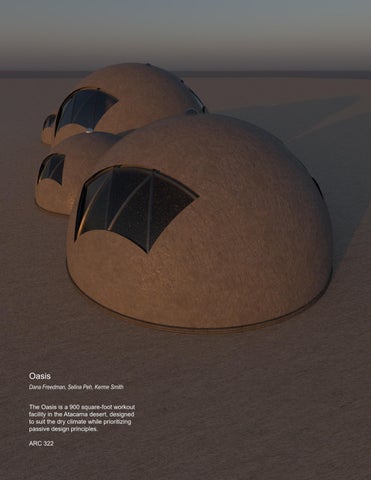
The Oasis is a 900 square-foot workout facility in the Atacama desert, designed to suit the dry climate while prioritizing passive design principles.
ARC 322 Oasis
Dana Freedman, Selina Peh, Kerme Smith
Table of Contents
Designing for Climate
Climate Analysis
Building Concept
Analysis of Building Adaptation to Climate
Passive Design in Action
Precedent Research
Climactic Strategies
Designing the Envelope
Detail drawings Life Cycle Analysis
Summer Wind
Winter Wind
Daily Summer Temp
Dailey Winter Temp
Daily Raidiation
Annual Raidiation
Annual Avg. Temp
Avg. Humidity
Avg. Precipitation
Vegetation and animals
Leaf Eared Mouse
Guanaco
Gray Fox
Chilean woodstar
Bromeliads
Herbaceous plant
Vulture
The Atacama Desert is clasified as a cold desert climate (BWk) under the Koppen-Geiger classification system. The region experiences relatively mild summer temperatures, with only slight variations between seasons. It recieves high levels of solar radiation from the sun all year round. The site is located on the leeward site of the Andes because it is sheltered from the wind, so it recieves very little precipitation. There are winds from the Pacific that bring moisture from the ocean in the form of fog but the droplets are too fine to fall as rain. Thus it gets humid during the summer. There is also drastic change in
The main program is situated underground to keep the space cool due to consistent low ground temps throughout the year to combat the high outdoor temperature in the desert. Lighting is provided from the windows in the dome as well as through a solar tube mechanism installed in the top of each tube. The building is completely passive, with ventilation and lighting systems that rely on natural environmental principles.
The main building concept consists of four concrete shelled domes arranged lengthwise along the site reinforced with a geodesic steel structure. Windows are cut out of the concrete dome following the steel structure. The building houses a gym complete with a reception area, workout space, locker room, bathrooms, and showers.
Exterior render Interior
The load bearing structure underground is composed of flat web steel sheet piles. It resist lateral loads from the surrounding soil with the tensile forces acting on the interlocking pieces. These sheet piles are a permanent fixture that driven deep into the ground at the beginning of construction and layers of waterproofing, insulation and finishing can be added once excavation of the site occurs. A concrete floor slab is then poured in situ into the excavated site. The underground structure serves as both foundational and programmatic systems of this project.
Additional layers of waterproofing, insulation and finishing are added on to the walls and floors after the construction of the loadbearing system. The steel piles are capped with concrete capping beams that circle round each of the domes, and serve as a footing for the geodesic steel structure of the domed roofs above.
Circulation through the building is sequential. Each program is accessed one at a time according to a sequence that provides convenience to the gym’s users. Communal spaces like the reception and gym are designed with a circular path to maximise use of the building’s round massing. This strategy was employed to adapt to the long, narrow site of the project.
The entrance of the gym is situated at the north end of the site near a foot path and the main road. A sheltered staircase leads down to the main reception area, which is buried 8 feet underground.The main gym area is 12 feet underground, and can be accessed via another set of stairs from the reception area. The lockers, bathrooms and showers are located on the same level as the gym.
The windows of the building are specifically oriented to take advantage of the climate characteristics of the site - they face southeast and southwest to avoid direct radiation and heat gain from the sun, while still providing an avenue for indirect lighting throughout the day. The southeast and southwest orientation also captures the predominant breezes throughout the year, allowing for consistent cross-ventilation to occur in each dome. The placement of the domes also supports this intention by ensuring that the windows are not blocked. These windows can be opened to allow for both cross and stack ventilation to occur.
The four domed masses are each lit up by Solatubes, a passive system that makes use of reflective mirrors to capture diffused sunlight from the surroundings, and direct it indoors. The dry climate of the Atacama desert is ideal for allowing quick evaporation of
sweat when accompanied by adequate ventilation. The windows on the roofs can also be fitted with fog catchers during the humid summer period to collect water from the surroundings.
The rationale of creating domed masses was to capitalise on the high thermal mass of concrete, and to ensure that no one orientation receives the bulk of solar radiation - a dome allows for the most equal distribution of radiation throughout the day. This diagram shows the annual radiation received by the concrete domesexcept for the base area facing the south, radiation received is consistent.
9am, dec 21
According to the radiation and illumination studies conducted to optimise the aperture and lighting placements in the design, the best way to ensure even lighting in the space throughout the day without excessive heat gain is to position the windows facing east-west. In the midday when the sun is highest in the sky and hottest, the Solatubes provide adequate lighting without inviting in excessive heat. They can also be removed to create another opening in the top of the roof for stack ventilation.
12 pm, dec 21
3 pm, dec 21
Scale: 1/8”- 1’-0”
Analysis of Building Adaptation to Climate
This diagram summarises the project’s adaptations to the Atacama desert’s climate, and programmatic needs of a gym and its users. It considers windflow and ventilation, solar radiation and lighting, as well as heat transfer across the envelope. Windows for cross and stack ventilation are paired with an earth air tunnel air cooling system to keep the space ventilated and cool. The high thermal mass of the concrete envelope above ground and underground structure further complement this strategy by slowing down heat transfer from exterior to interior.
Aloni House, situated on the Greek island of Antiparos, is an example of climate responsive architecture, blending seamlessly into the natural landscape of Antiparos, Greece. The house takes advantage of earth sheltering, a passive design strategy that uses the earth’s thermal mass to regulate indoor temperature and reduce the need for mechanical heating and cooling.
The design attempts to minimize exposure to strong winds while capturing natural ventilation and sunlight. Integrated naturally into the landscape, this reduces visual impact and improves natural insulation, making the building energy efficient and, connected to its landscape, and adapted to its climate.
Saieh, Nico. “Pearl Academy of Fashion / Morphogenesis.” ArchDaily, November 13, 2009. https:// www.archdaily.com/40716/pearl-academy-of-fashion-morphogenesis.
Another example of climate-responsive architecture is the Pearl Academy of Fashion by Morphogenesis Architects in Jaipur, India. This building several passive cooling strategies in order to reduce energy use and maintain comfort in the hot desert climate. It has an earth air tunnel system, in which air is drawn through underground pipes through the earth and then circulated inside the building. This greatly cuts down on the need for mechanical air conditioning.
Project: Shell Home
Architect: Binishells Inc.
Location: Malibu, California
Year construction completed: 2022
Passive strategy: thermal mass envelope (day cooling/ night heating) + evaporative cooling (cooling)
3. continuous, curving concrete shell thermal mass minimises thermal bridging
Shell Homes, dome-like structures made of reinfroced thin-shelled concrete, are developed with passive strategies to optimize interior comfort. One design strategy is evaporative cooling, in which the structure promotes airflow that cools the interior through the evaporation of moisture. Other features include thermal massing, in which the thick concrete walls absorb and store heat gained during the day and slowly release it at night, stabilizing indoor temperatures. The use of light-colored surfaces also reflects solar radiation, minimizing heat absorbtion.
Ott, Clara. “Shell Home / Binishells Inc..” ArchDaily, August 1, 2024. https://www. archdaily.com/1017819/shell-home-binishells-inc.
1. evaporative cooling through operable vents
2. light colored surface re ects radiation from sun
1. evaporative cooling pools
Project: Eastgate Building
Architect: Mick Pearce
Location: Zimbabwe
Year construction completed: 1996
Passive strategy: thermal mass envelope (day cooling/ night heating) + stack ventilation (cooling)
The Eastgate Building takes advantage of natural stack ventilation and thermal mass for indoor temperature regulation. This building is made of thick concrete and has a high thermal mass, absorbing heat during the day and releasing it at night to maintain indoor temperatures.
Pearce, Mick. “Eastgate Building.” Eastgate Building Harare. Accessed October 19, 2024. https://www.mickpearce.com/Eastgate.html.
Air Extraced From the O ce
Air Intake Fans
Cool Air from Atrium
Concrete Floor
Cold Air
Hot
In the desert city of Yazd, Iran, vernacular windcatchers are an ingenious traditional architectural feature, allowing natural ventilation and cooling. Tall, tower-like structures, they capture prevailing winds and channel them down into buildings where the cooler air is funneled through interior spaces. Under the hot and dry Yazd climate with extreme temperatures and low humidity, windcatchers become an essential element in the creation of a comfortable indoor environment. They are usually designed to work together with subterraneous waterways, qanats, that cool the air even further as it is crossing over running water, providing a passive cooling system that functions without depending on mechanical ventilation systems.
Project: Iranian Windcatcher
Architect: vernacular architecture
Location: Yazd, Iran
Year construction completed: date back to the 13 century Passive strategy: windcatcher/windtower (cooling)
Project: Casa Caldera
Architect: DUST
Location: Arizona, USA
Year construction completed: 2015
Passive strategy: cross ventilation (cooling)
Casa Caldera is located in the dry desert of Arizona. The region has extreme temperatures, low humidity, and dust. The cooling strategy at Casa Caldera allows natural air to flow through the building, facilitating cross ventilation. Its thick adobe walls have a high thermal mass, absorbing heat during the day and releasing it at night, helping to regulate indoor temperature. As a result of this design, very little mechanical cooling is necessary, while the sheltered courtyard of the home and windows minimize dust infiltration, provide additional ventilation, and frame the desert landscape.
Hernandez, D. (2016, May 4). Casa Caldera / Dust. ArchDaily. https://www.archdaily. com/786813/casa-caldera-dust
Airflow
Low window opening
Cold air drawn in
High window opening
Warm air rises and is expelled
Warm air is expelled
Cool air enters
Interior spaces cooled
1
At night, the high thermal masses slowly releases heat absorbed from the sun throughout the day back into the interior, warming up the gym. This is useful due to the diurnal temperature swings of the Atacama desert, ensuring that the interior spaces remain at a relatively consistent temperature. This supports the strategy of building underground to maintain consistently cool interior temperatures.
The rationale of creating domed masses was to capitalise on the high thermal mass of concrete, and to ensure that no one orientation receives the bulk of solar radiation - a dome allows for the most equal distribution of radiation throughout the day. This diagram shows the annual radiation received by the concrete domesexcept for the base area facing the south, radiation received is consistent.
South facade - 9am
South facade - 12pm
South facade - 3pm
North facade - 9am
North facade - 12pm
North facade - 3pm
Interior plan highlighting air movement
Hot air exiting through windows via Stack E ect
Cool air entering through Wind Tower
Wind Tower
Roof plans highlighting winter winds and cross ventilation
Keeping the building space partially underground helps to fulfil the programmatic need of having a taller, well-ventilated workout space for the gym. It also helps to facilitate stack ventilation when the windows are open, keeping the main gym space cool and comfortable for users.
Operable Windows on the domed roof
Winter Wind from the W and SW
Winter wind cooling the interior through Cross Ventilation
Roof plans highlighting summer winds and cross ventilation
Air entering through by the stairs
Summer wind from the E and NE
Winter wind cooling the interior through Cross Ventilation
Operable Windows on the domed roof
Lower
night to keep
Louvre closed at night limits ventilation to keep interior warm
Windows closed Limits ventilation to keep interior wwarm
Air wamed by the earth 45°F outside air temperature
Temperature
Wind Tower
Earth Air Tunnel
Earth
55°F Passive Radiative Heating due to Earth Sheltering
Thermal Mass and Earth Sheltering Diagrams
The building takes advantage of earth sheltering, a passive design strategy that uses the earth’s thermal mass to regulate indoor temperature and reduce the need for mechanical heating and cooling.
Releases heat into the
45°F
Strategy 1: Concrete thermal mass (day cooling/night heating)
Strategy 3: Earth air tunnel used in conjunction with wind tower (day cooling/night heating)
Windows for cross and stack ventilation are paired with an earth air tunnel air cooling system to keep the space ventilated and cool. The high thermal mass of the concrete envelope above ground and underground structure further complement this strategy
braced corrugated steel piling (permanent) 3ft wide corrugations, material is 1/4” thick
concrete wall
8” thick, reinforced with rebar mesh
Peca ll nish - brand of vapor retarder and smooth surface to build upon steel piling
batt/sheet insulation
3” thick
airtight, triangular aluminium window frames
low-e, low SHGC windows
This wall assembly is a passive design and envelope strategy with an emphasis on energy efficiency and durability. This layered assembly allows maximum energy conservation through controlled heat flow and moisture management, creating comfort while providing a durable and highperformance envelope for the climate of the Aticama Desert.
oor nishing
foundation concrete slab, 8” thick: sheet piling is built into this foundation slab
Detail exploded axon of dome wall layers
XPS foam insulation, 3” thick
exterior concrete nish (shotcrete) ~1” thick
low-e, low SHGC glass window panels
The exterior wall system highlights principles of passive design through the use of an advanced envelope strategy, with emphasis placed on insulation and thermal mass efficiency in the regulation of energy. The exterior finish is a shotcrete durable finish, providing durability and weather protection. Beneath sits spray insulation for thermal resistance, supported by a vapor retarder that controls moisture. The structure is a geodesic steel frame, with steel bars encased within the concrete surface, with concrete on either side to maintain structural integrity. An concrete shell inside acts as the primary thermal mass. Embedded window frames support flat triangular low-e, low-SHGC glass panels to enhance thermal performance while minimizing heat gain.
vapor retarder
urethane spray insulation (closed-cell) ~3” thick
metal supporting structure, geodesic conguration ~1” thick steel bars, welded together
interior concrete shell ~8” thick window frames
interior wall nish footing
Detail 1
braced corrugaated steel piling ~3’ wide corrugations, material is 1/4” thick
hollow structural steel (in geodesic con guration)
vapor retarder
spray urethane foam (~3” thick)
exterior concrete nish (~1” thick)
air gap
weep hole
shotcrete shell layer (8” thick)
concrete ring footing (meets ground level; embeds concrete shell dome and steel sheet piling)
vapor retarder hollow structural (in geodesic con
steel sheet piling (structural)
spray urethane
supporting steel sheet bracing for main piling wall
exterior concrete
Chunk 1, detail 3 drawings
concrete ring footing
gypsum board nish
batt insulation - 3” thick
concrete wall
peca ll membrane (waterproo ng + vapor barrier)
steel sheet piling
supporting steel sheet bracing
Vapor Barrier
Concrete
Peca ll
Waterproo ng
Membrane
Sheet piling
The foundation structure consists of a concrete slab, reinforced with sheet piling to provide stability, while an outer layer of braced corrugated steel piling forms the long-term structural system. High-performance insulation allows for the reduction of heat transfer. Pecall finish acts as a vapor barrier, ensuring a smooth surface and preventing moisture from entering. A reinforced concrete wall completes the assembly, optimized for thermal mass and strength.
Floor Slab
Crushed Stone
Drain pipe
Wall Finish Insulation
Rebar
ll
Sheet piling
Concrete
Peca
Gpysum Board Insulation
Rebar
Concrete
Blocking
Anchor
Steel Door Frame
Door
Wall Finish Insulation
Sheet piling
Floor Finish Insulation
Rebar
Concrete
Peca ll
Rebar
Concrete
Peca ll
Concrete
ALTERNATIVE APPROACH:
Interior air and vapor control is executed by placing the vapor barrier on the interior of the insulation layer, ensuring that vapor from themore humid interior does not get to the colder inner surface of the exterior concrete wall
Average temperature range consistently remains above dew point: however, average temperature is not a meaningful measure as it is not re ective of the large diurnal temperature swings Dew point at 35% RH, 70°F (interior temperature of gym) is approximately 40°F
Coldest temperatures at night from Mar to Nov drop signi cantly below dew point
HOWEVER, we chose not to add exterior insulation to prevent condensation, as that insulation would obstruct the concrete wall’s function as a thermal mass
ALTERNATIVE APPROACH:
Interior air and vapor control is executed by placing the vapor barrier on the interior of the insulation layer, ensuring that vapor from the more humid interior does not get to the colder inner surface of the exterior concrete wall.
Average ground temperature range consistently remains above dew point: little to no danger of condensation within wall layers, so no exterior insulation is added
Dew point at 50% RH, 70°F (interior temperature of gym) is approximately 50°F
Dew point at 35% RH, 70°F (interior temperature of gym) is approximately 40°F
Life Cycle Analysis
The LCA results from our Athena simulation are summarized in the tables below, accounting for all materials and layers used in the building’s concrete foundations, floors, underground walls, and domed roofs. The simulation generates a whole life carbon report, accounting for both embodied and operational carbon released by the building throughout its lifetime, from production and construction (A), operation (B), end-of-life demolition processes (C) and recycling/reuse of building material (D). These categories of emissions make up the total carbon footprint of the building throughout its entire lifetime. Overall, the carbon footprint of the building is rather evenly split between embodied and operational carbon throughout its lifetime.
The bill of materials breaks down the individual materials used in assembling the walls, roofs and floors of the building. Steel makes up a significant proportion of the bill of materials due to its role as the structural/load-bearing material for both the underground walls and domed roof portions of the building. A significant amount of concrete is used as well in the project because it makes up the main domed geometry of the building masses, as well as the foundations of the building.
Global warming potential (GWP) is a measure of the building’s carbon footprint based on the amount of embodied and operational carbon released by the building throughout its lifetime.
Since the embodied and operational carbon released by the building is roughly equal, it is possible to conclude that there is more to be done in terms of reducing the operational emissions of the building. The simulation results point towards the effectiveness of implementing renewable energy sources for the building like solar panels to offset the significant operational carbon GWP of this design.
Operational energy usage calculations: Natural gas usage is assumed to be 0 as building is designed to be passively heated and cololed, electricity is used only fore appliances.