DIVYA_KOLI
SELECTION OF PROFESSIONAL AND ACADEMIC PROJECTS 2018-23
VVAVVVVV PORTFOLIO PORTFOLIO ARCHITECTURE INTERIOR INTERIOR ARCHITECTURE LANDSCAPE LANDSCAPE
DIVYA_KOLI
An architecture designer eager to pursue my passion in structural and landscape design. Architecture, in my opinion, is not about form, but about the standards and cultural aspects that we choose to preserve. A critical thinker whose goal is to create all Sustainability-oriented spaces. I am currently searching for a job that will assist me in expanding my skills, gaining practical knowledge, and pushing the boundaries.
LANGUAGE PROFICIENCY
MASS HOUSING WORKSHOP - AR YATIN PANDYA
CLIMATOLOGY WORKSHOP - AR SHIVRAM AND AR KULDEEP
WORKSHOPS ABOUT
MURAL - ADITYA BIRLA GROUP
BORIVALI COLUMN PAINTING - BMC
DEPLOYABLE WORKSHOP
BAMBOO WORKSHOP
WEBINARS
A DESIGN PRACTICE - AR RASHNA KAPADIA

TAKING THE LINE FOR A WALK - AR SANJAY MHATRE
CHARLES CORREA MEMORIAL SEMINAR - AR ROHAN SHIVKUMAR
LANDSCAPE DESIGN - AR SRIGANESH RAJENDRAN
EARTHQUAKE RESISTANT WEBINAR SERIES - AR SANGEETA DATE
DOCUMENTATIONS
KARNATAKA : VITHALA TEMPLE BADAMI CAVES
AIHOLE : LADHKHAN TEMPLE DURGA TEMPLE PATTADAKHAL
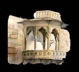
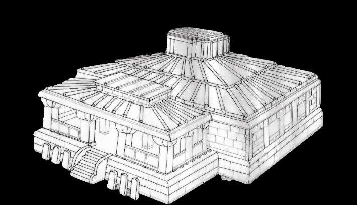
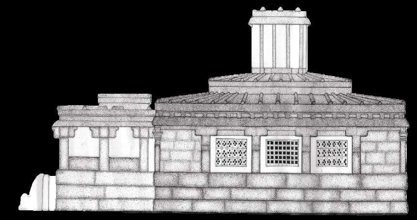
RAJASTHAN : JASWANT THADA
HIMACHAL PRADESH : GARLI OTHER SKILLS
TEAMWORK MANAGEMENT INNOVATIVE COMMUNICATION

WORK EXPERIENCE
Architecture Internship : STUDIO 55, Pune.
STUDIO 55 is a young design-oriented practice working in the fields of architecture and interior design. They have formed a design association with Raymond Hall Ltd. based in London and Hall Black Douglas based in belfast ,UK. Ideally placed to deliver high quality architectural, interior, and urban design in India.
Principle Architects : AR. SIDDHARTH RAJURKAR


AR. GIRISH MOHILE
COA no : CA/2010/47824


CA/2010/47835
Location : Pune, India
ENGLISH HINDI MARATHI
ACADEMIC STUDIES
2004-2016
SOFTWARE SKILLS
HIGHER SECONDARY CERTIFICATE: Nirmala Memorial Foundation, Kandivali (w), Mumbai

SECONDARY SCHOOL CERTIFICATE: Mary Immaculate Girls High School, Borivali (W), Mumbai .
2016-2018

HANDS ON STRENGTHS
2018-2023
INTERNSHIP : STUDIO 55, Pune


B.Arch: Aditya College Of Architecture, Borivali (w), Mumbai -400103.
HOBBIES
2021-2022
NATIONALITY : Indian D.O.B - 02-05-2000
DAHISAR (W),MUMBAI -068
kolidivya2000@gmail.com

+91-9969964369
divya_koli.02 art_creatif.02
COMMUNICATION DECISION-MAKING
GRAPHIC DESIGN
MUSIC TEAMWORK
SKETCHING DRAFTING MODEL-MAKING TRAVELLING
LLOYD WRIGHT
“AN IDEA IS SALVATION BY IMAGINATION.” -FRANK
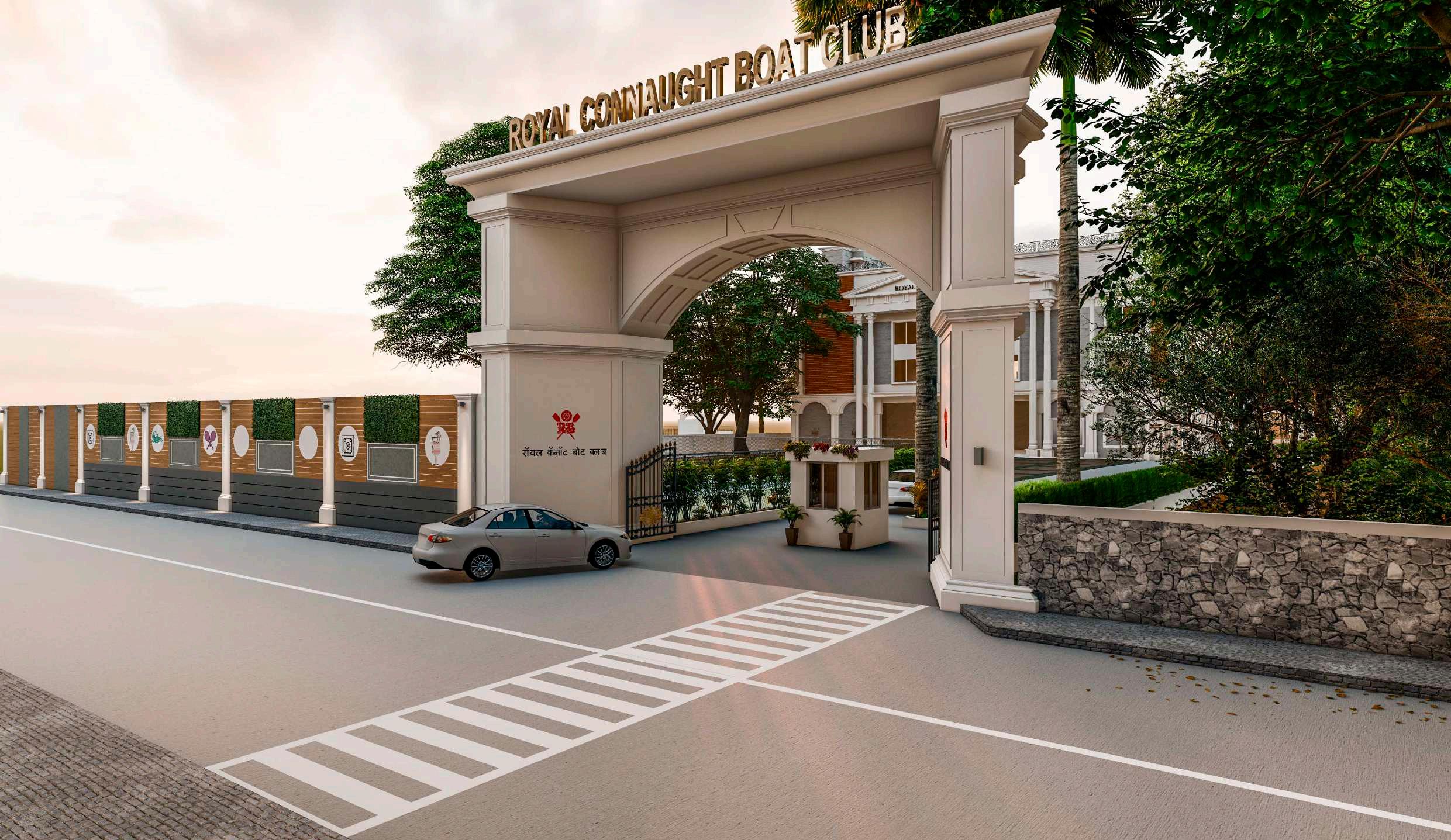
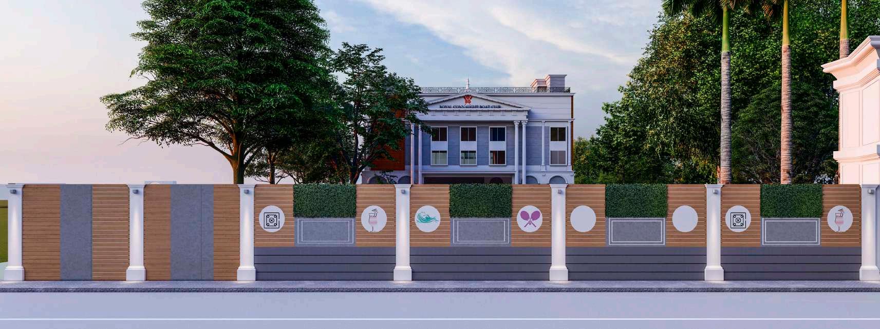
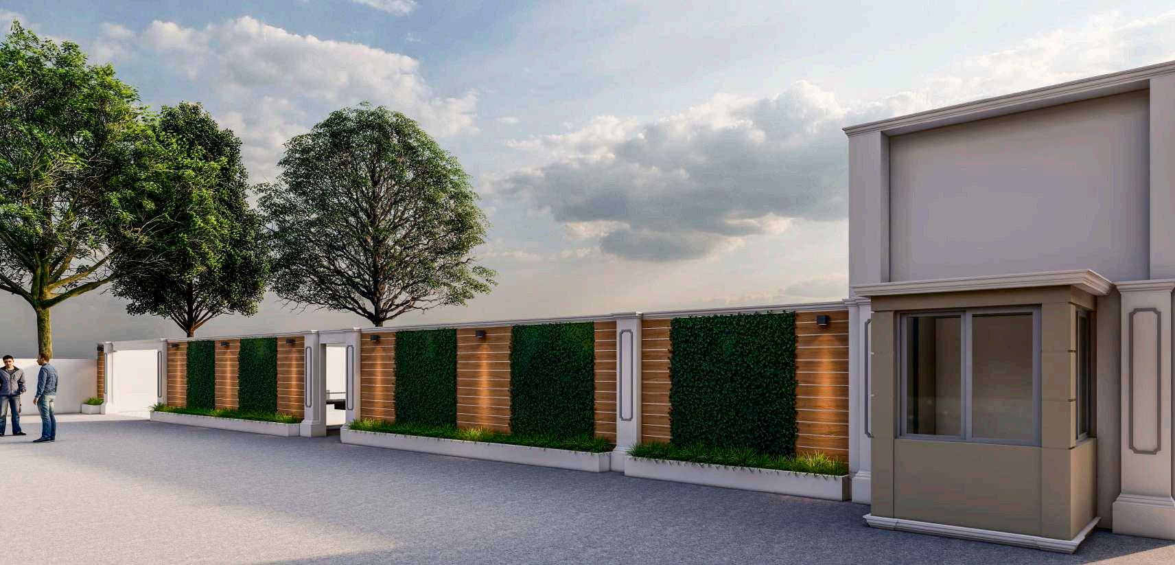
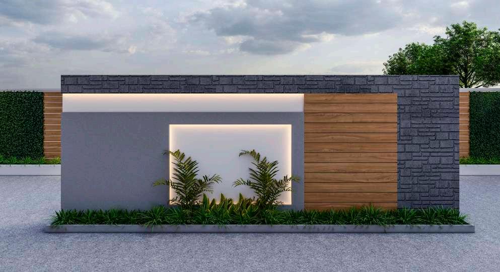
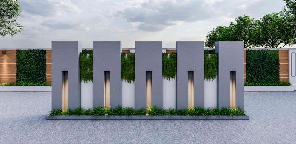
ROYAL CONNAUGHT BOAT CLUB
OFFICE SPACE INTERIOR AT WEST PORT
BHIMALE RESIDENCE
GAUTAM APARTMENTS
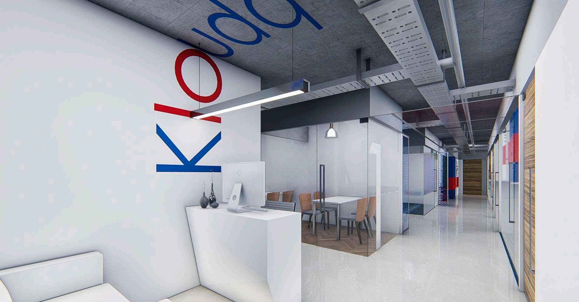
KLOUD Q
ARCHITECTURAL DESIGN
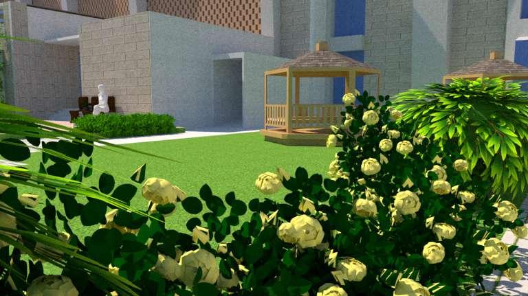
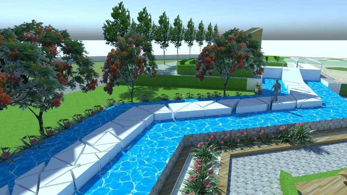
SEM 04: RESORT LANDSCAPE SITE: JODHPUR , RAJASTHAN
SEM 06:
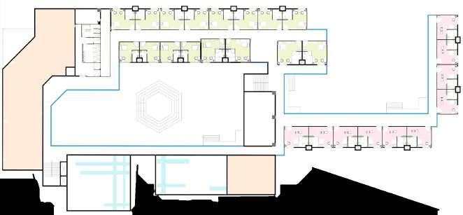
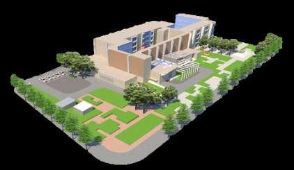
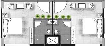
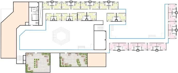
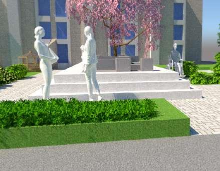
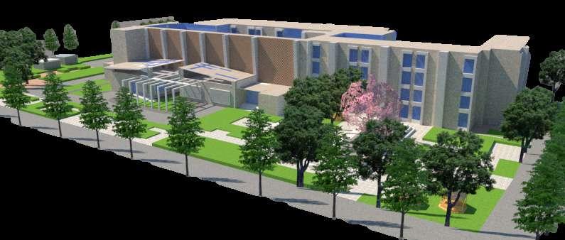
WORKING WOMENS HOSTEL SITE : BORIVALI, MUMBAI, INDIA
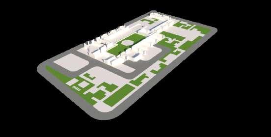
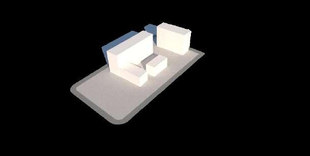
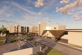
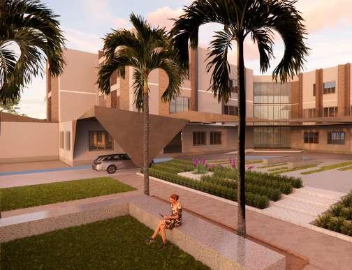
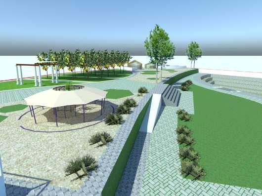
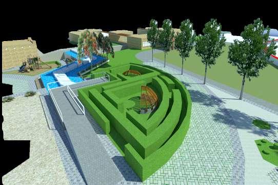
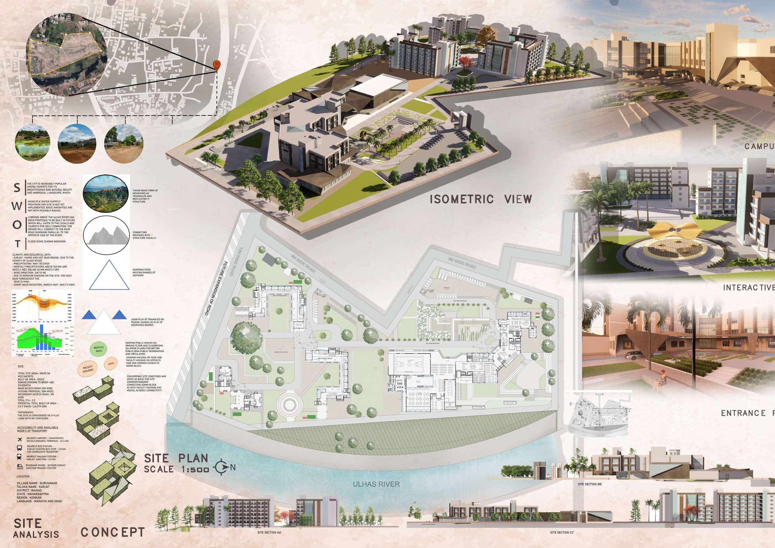
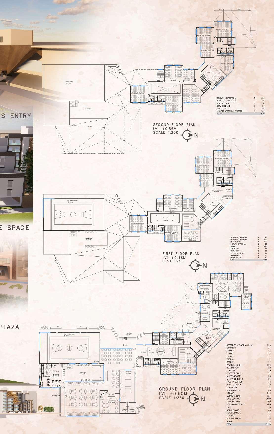
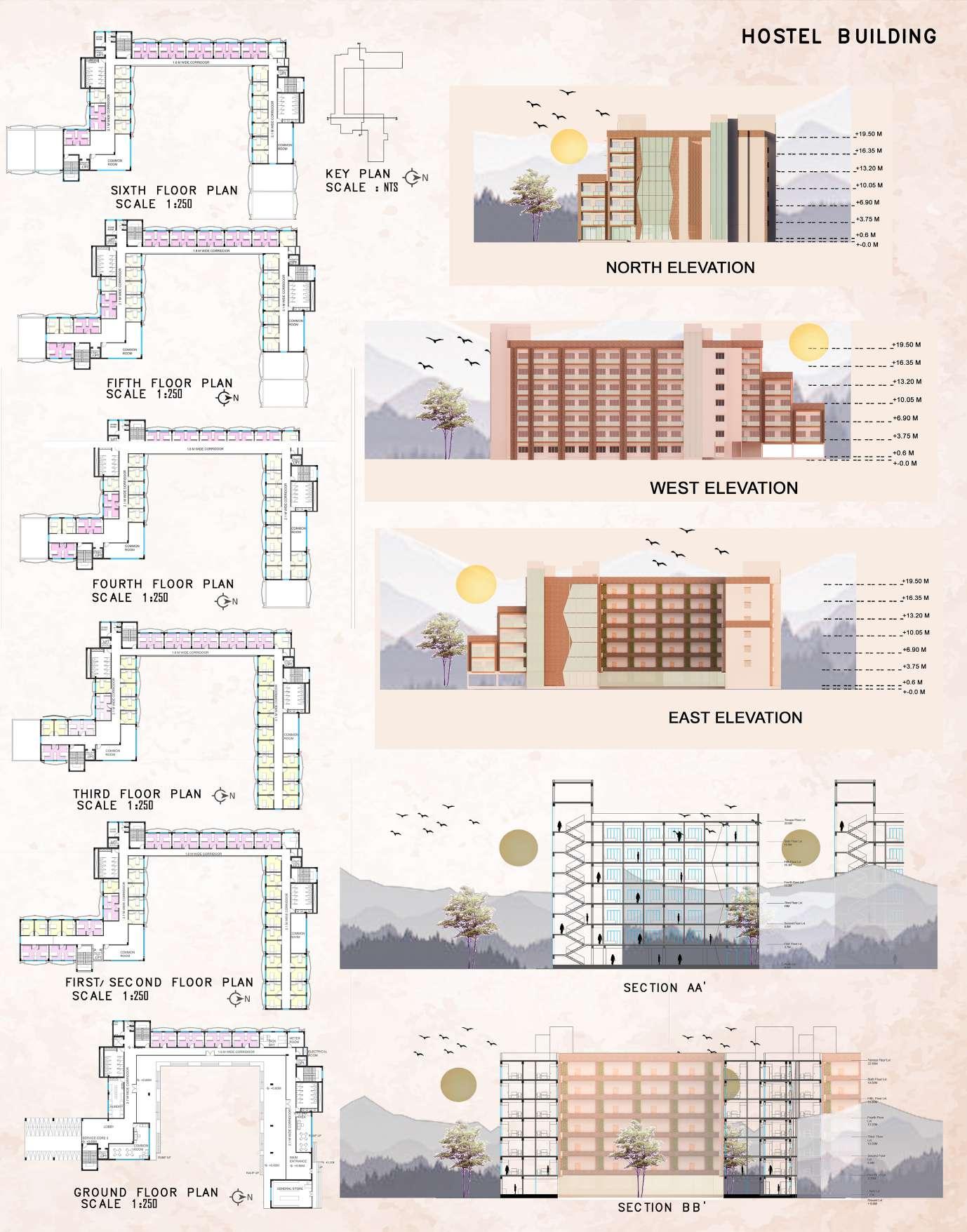
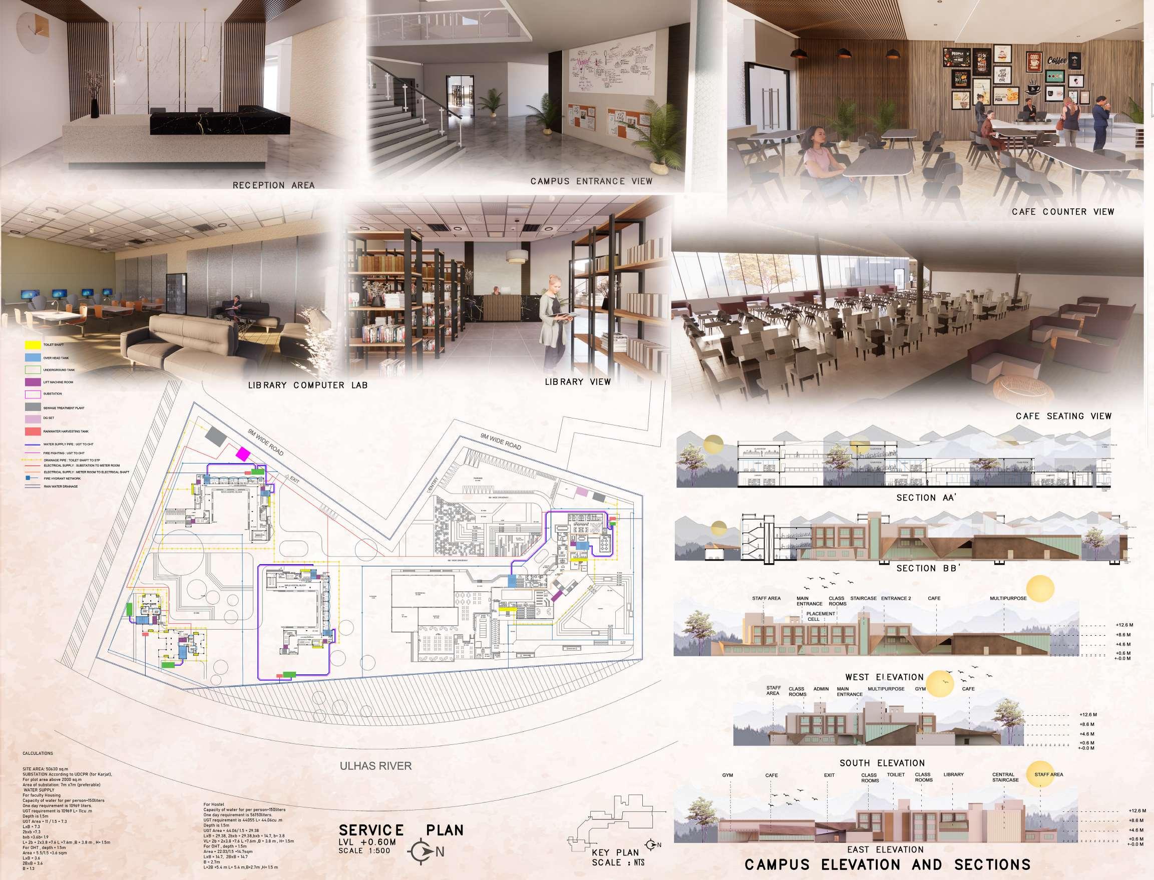
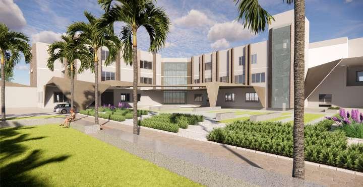
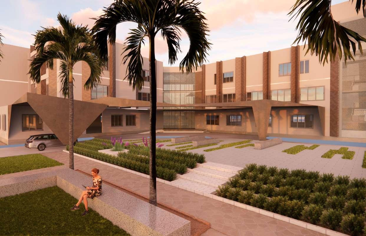
SEM 09: MANAGEMENT INSTITUTE SITE: KARJAT, MAHARASHTRA
INTERIORS
CAFETERIA STUDIO APARTMENT
MISCELLANEOUS
MURAL PAINTING : ADITYA BIRLA BORIVLI COLUMN PAINTING: BMC
BAMBOO WORSHOP SKETCHES
DOCUMENTATION


KARNATAKA : VITHALA TEMPLE BADAMI CAVES
RAJASTHAN : JASWANT THADA HIMACHAL PRADESH :GARLI
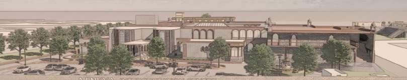
VVAVVVVV THESIS : AJINKYA - INTERPRETATION CENTRE, ARNALA
VVAVVVVV
P R O F E S S I O N A L P R A C T I C E A C A D E M I C S
professional practice C O N T E X T
SEM 04 : RESORT LANDSCAPE
SITE: JODHPUR , RAJASTHAN
SEM 06 : WORKING WOMENS HOSTEL
SITE : BORIVALI, MUMBAI, INDIA
SEM 09 : MANAGEMENT INSTITUTE
SITE: KARJAT, MAHARASHTRA
SEM 10 :


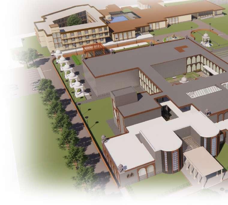
THESIS : AJINKYA - INTERPRETATION CENTRE, ARNALA


INTERIORS
CAFETERIA
STUDIO APARTMENT


ACADEMIC WORK 2018-2023
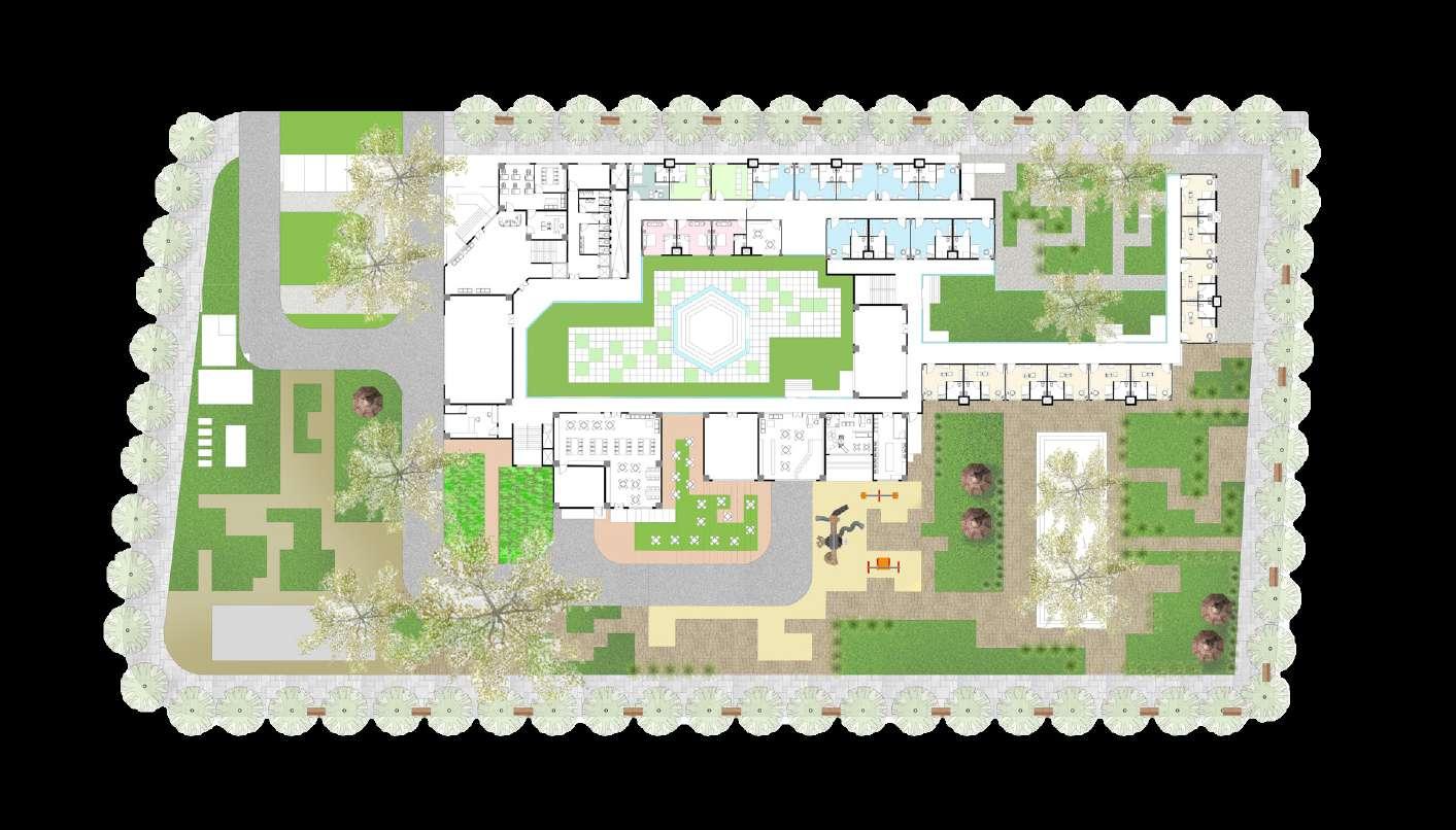
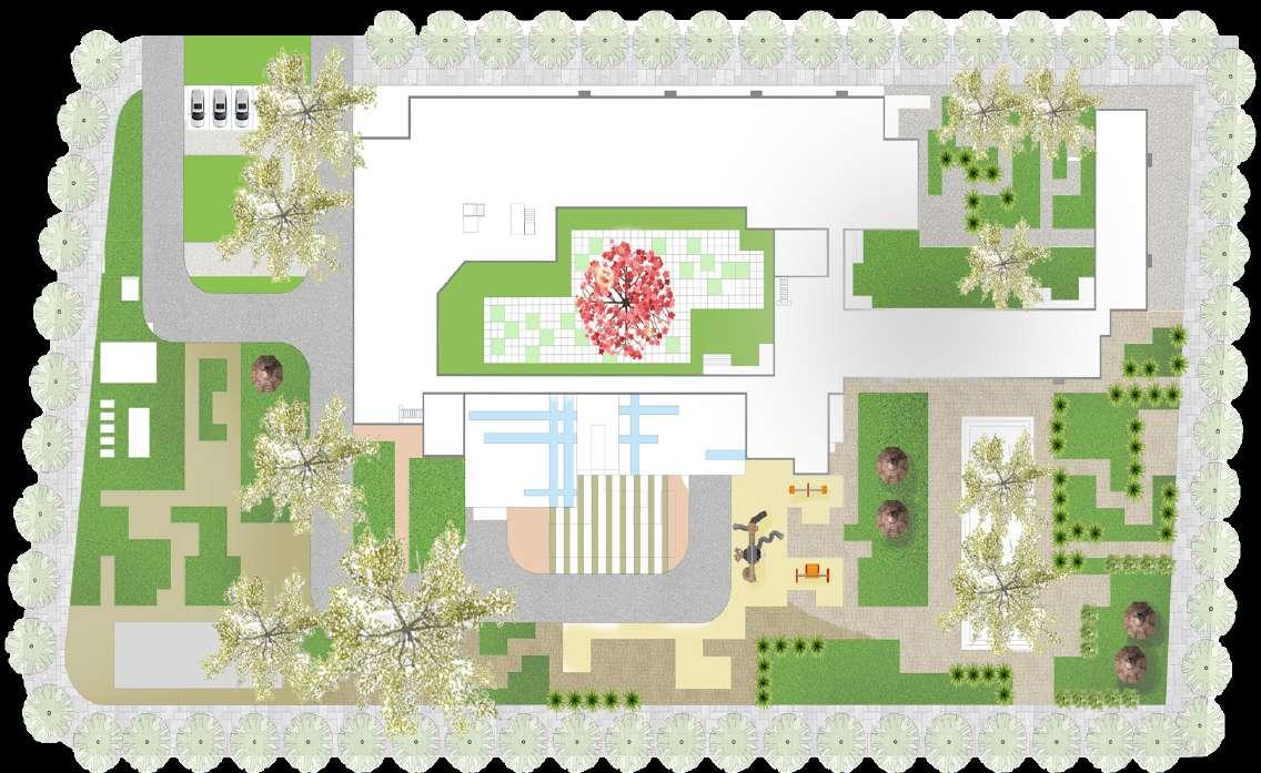
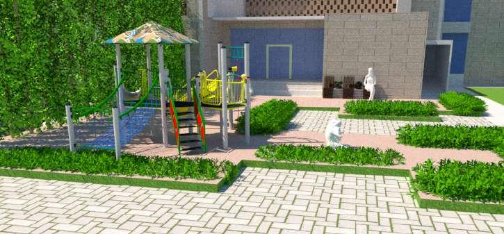
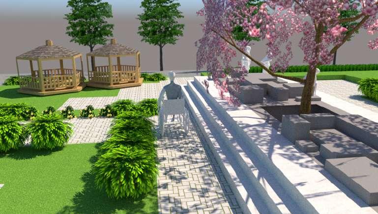
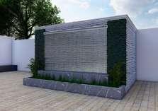
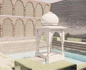
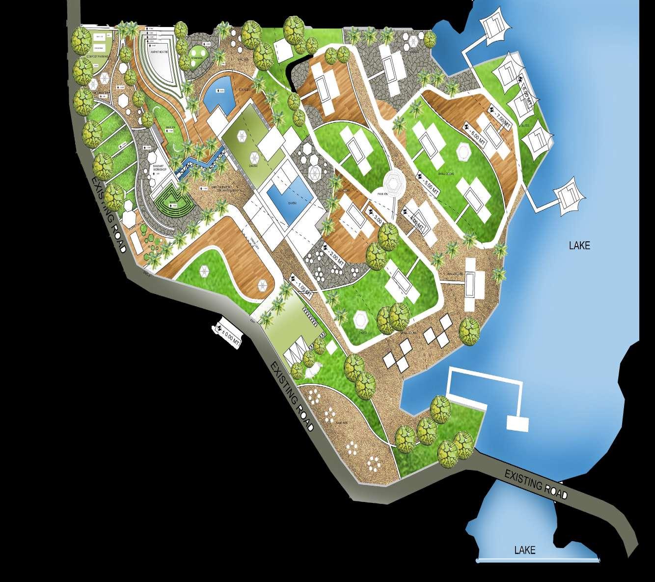
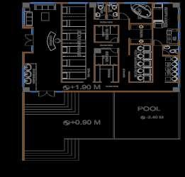
THE DESIGN IS INSPIRED FROM LOCAL CULTURE AND TRADITIONAL ARCHITECTURAL STYLE OF JODHPUR. THE DESIGN FURTHER PROCEEDED BY USING NATURALLY AND LOCALLY AVAILABLE MATERIALS SUCH AS SANDSTONE. THE AREA IN CONSIDERATION PROMOTES ACTIVITES SUCH AS ORGANIC FARMING , SAND ART WORKSHOPS , PUPPET SHOWS, AMPHITHEATRE AND SPA AREA. SERVICES INCLUDE CATCHMENT AREAS, RAIN WATER HARVESTING, USE OF SOLAR PANELS TO ENHANCE SELF SUFFICENCY AND LOW CARBON FOOTPRINT.
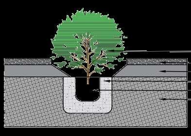
SINCE THE SOIL ON THE SITE IS NOT FERTILE ENOUGH FOR FARMING, A LOCAL MINERAL NAMED DOLOMITE IS USED, WHICH HELPS IN REGULATING THE PH LEVELS OF SOIL MAKING IT FERTILE FOR CULTIVATION, COMPOST AND MANURE CULTIVATION
SITE LOCATION : KALYANA LAKE , JODHPUR
SITE AREA : 64000 SQ M AREA CONSIDERED FOR LANDSCAPE DESIGN: 25000 SQM TOPOGRAPHY : CONTOURS RANGE FROM 0 TO -8 M . KALYANA LAKE LOCATED TO ITS NORTHEAST. THE REGION FALLS UNDER THE CATEGORY OF HOT SEMI ARID ZONE.
AIM : TO DESIGN AS EXPERIMENTAL LANDSCAPE FOR LAKESIDE ECO-RESORT ENHANCING THE VALUE ALONG WITH SITE CONTEXT.
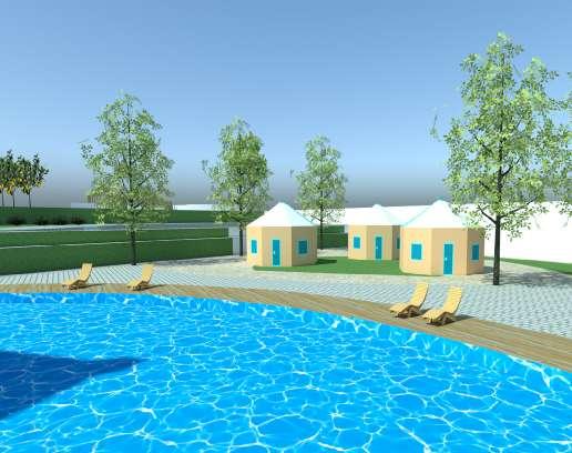
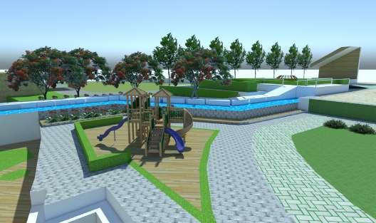
OBJECTIVES: TO UNDERSTAND THE NATURAL SETTING OF THE SITE. TO INCULCATE THE DEEPLY ROOTED CULTURAL ASPECTS TO THE SITE IN FORM OF LANDSCAPE. TO CREATE SENSUAL EXPERIENCE. TO UNDERSTAND THE CONSTRUCTION DETAILS.
MANAGEMENT INSTITUTE,KARJAT
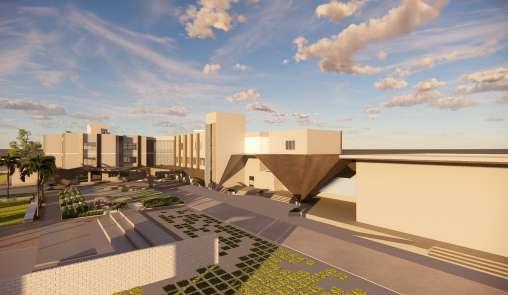
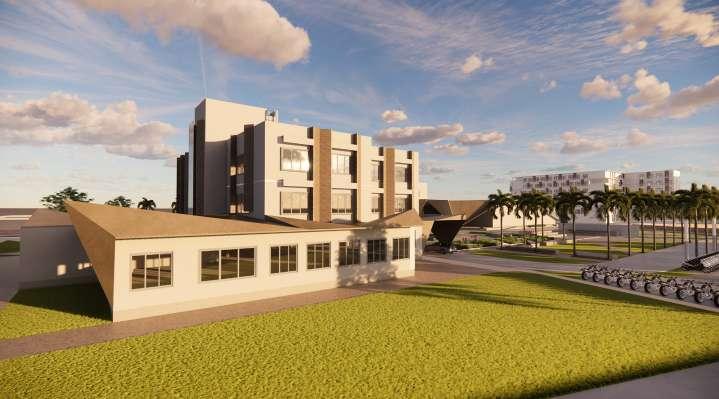
V I E W S
“India is not, as people keep calling it, an underdeveloped country, but rather, in the context of its history and cultural heritage, a highly developed one in an advanced state of decay”


-Shashi Tharoor
ARE WE WELL VERSED WITH OUR LOCAL CULTURE?
WHAT IS HERITAGE ? IMPORTANCE ??
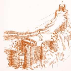
WHAT DO FORTS REPRESENT ?
NEED FOR CONSERVATON ? REVENUE ??
LACK OF AWARNESS ?? GOVERNMENT POLICIES ?
WHAT MEASURES CAN BE TAKEN WHICH WILL CONTRIBUTE IN RETRIVING MEDIVAL KNOWLEGE OF ART AND ARCHITECTURE ?


CHARIOTS / SHOPS
WORSHOP, SOUVENEIR SHOP

ARTISANS AUDITORIUM
STABLES
HISTORY GALLERIES
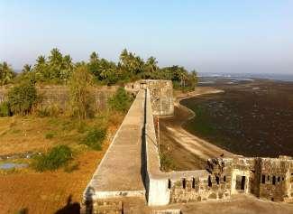
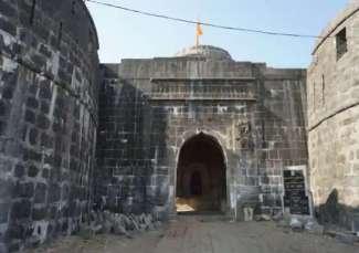
ARNALA FORT
S
FORT ON ISLAND : JANJIRE ARNALA
RICH HISTORIC PAST
LEFT IN THE STATE OF RUIN
YET THERE IS SCOPE FOR RESTORATION
THE FORT IS UTILIZED BY THE INHABITANTS FOR FARMING.
INSPITE THE CURRENT CONDITION THERE IS STILL CONSIDERABLE AMOUT OF TOURIST VISITING THE FORT.

PROBLEMS IDENTIFIED IN THE VICINITY IF THE FORT
PEOPLE LIVING ON THE ISLAND HAVE BEEN DEPRIVED OF MANY FACILITIES INCLUDING FEASIBLE COOMUTE.
THE ONLY WAY OF TRANSPORTATION IS THROUGH SMAL BOATS

THUS THERE ARE VERY FEW AUTOMOBILES ON THE ISLAND.
NO HOSPITALS OR HEALTHCARE FACILITIES ARE AVAILABLE IN CASE OF EMERGENCIES.
ONLY PRIMARY EDUCATION ID PROVIDED FOR SECONDARY AND HIGHER EDUCATION THE STUDENT HAVE TO TRAVEL TO VIRAR AFTER CROSSING THE ISLAND THROUGH BOAT.
WATER SCARCIY IS OBSERVED DURING CERTAIN PERIOD OF THE YEAR WHEN THE LEVEL OF GROUND WATER TABLE IS LOW

W O T
STRENGTHS
1. Located at the threshold of greater Mumbai
2. Strong rail and road connectivity with the metropolis
3. hilly rolling terrain with excellent forest cover and scenic charm
WEAKNESS
1. Has low profile with no identity of its own


2. There is extreme scarcity of drinking water
3. There is no underground sewerage system
OPPORTUNITIES
1. Large chunks of open land available for future development

2. Good potential for water front development for use as water transport, water sports THREATS
1. Illegal and haphazard development may take place on salt pan land
2. Scarcity of drinking water may stunt further growth of city
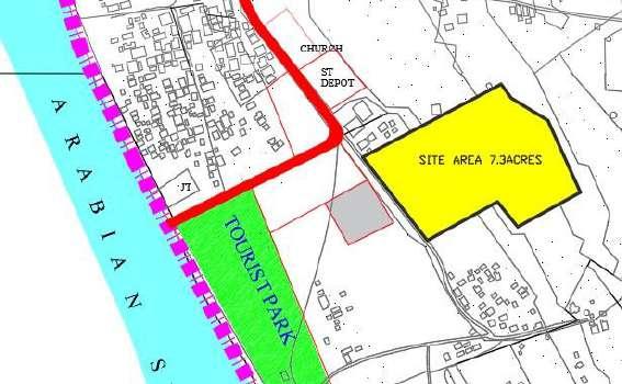
SITE ACCORDING TO DCPR

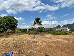
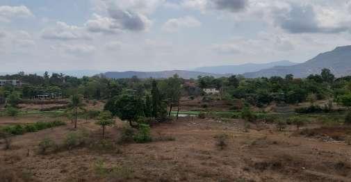
SITE VIEWS
SITE SURROUNDINGS
ENTRY/ EXIT TO SITE VIA
AVERAGE TEMPERATURE VASAI-VIRAR CLIMATE: tropical wet and dry climate HUMIDITY Humidity ranges from 49% to 85% with the highest humidity in the month of July. (Vasai Virar City Development Plan under scheme of UID in Satellite Towns)
WIND DIRECTION: The wind direction is predominantly from, west and southwest for a major period of the year . the mean wind speek is 16.52 km/hr.
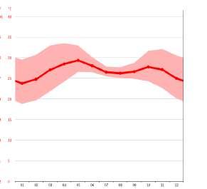

(Vasai Virar City Development Plan under scheme of UID in Satellite Towns, n.d.)
SOIL TYPE: Alluvial And Loamy
vv
ROYALS/ BRAHMINS TOURIST ACCOMODATION
KSHATRIYA ACCOMODATION / GRAIN STORAGE RESEARCH AND DEVELOPMENT CELL
KITCHEN CAFÉ , RESTURANT, BANQUET
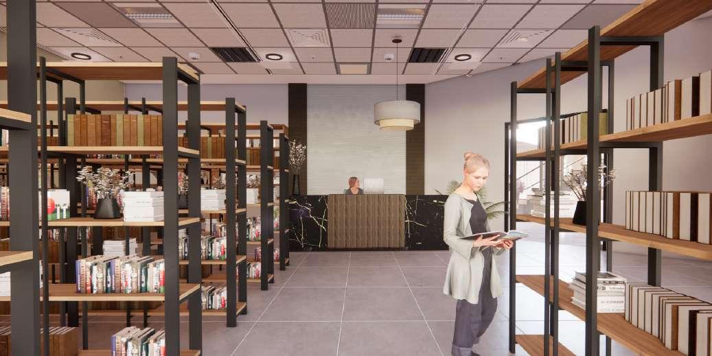
TREASURY LIBRARY
STOREHOUSE VIRTUAL REALITY SCREEN
SPA
-
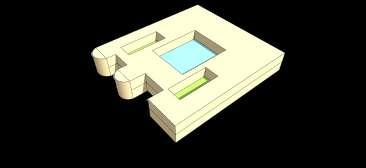
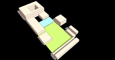
Layout Of Fort According To Arthashastra And Its Amalgamation With Modern Requirements
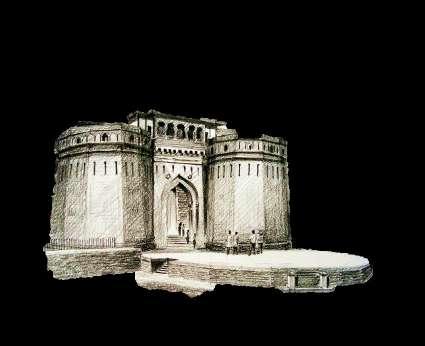
HERITAGE INTERPRETATION CENTRE, ARNALA
Entrance
Rampart
Arnala Island
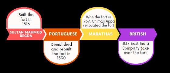
TIMELINE OF RULERS OF ARNALA
EXISITING SETTLEMENTS EXISITING ROAD PROPOSED ORGANISED OPEN SPACES PROPOSED ROAD PARKING LOT
FORM EVOLUTION TOURIST ACCOMODATION Adminstration State Government SECONDARY USER
IDENTIFICATION PRIMARY USER Tourists Koli Community ASI Other Locals SITE AREA 7.3 ACRES CLIMATE ANALYSIS
MONTH VASAI-VIRAR
USER
WEATHER BY
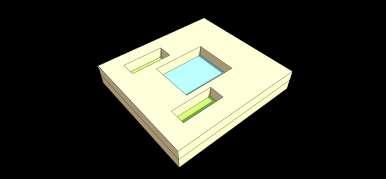
ISOMETRIC VIEW
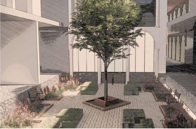
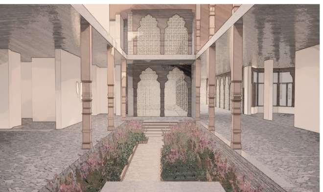
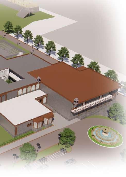
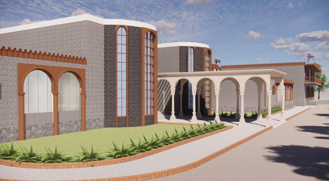
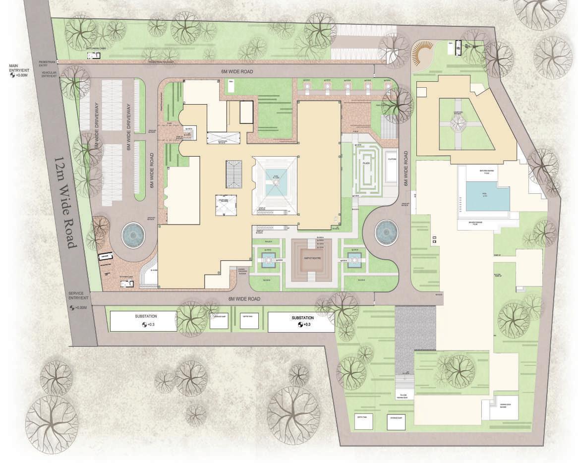


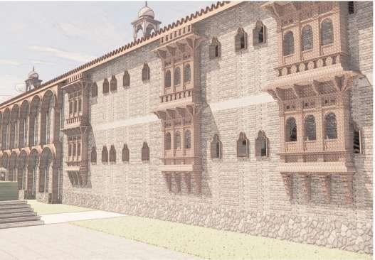
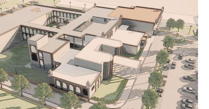
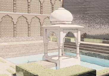
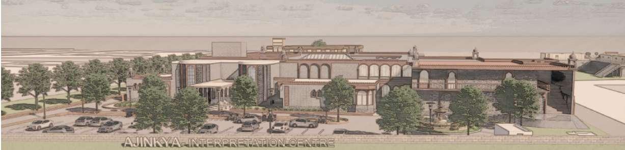

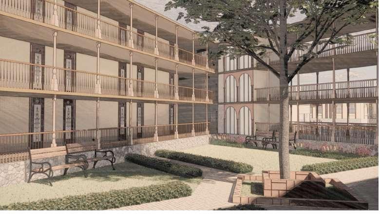
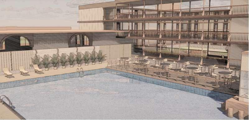
INTERPRETATION CENTRE TOP VIEW KUNDVIEW INTERPRETATION CENTRE COURTYARD INTERPRETATION CENTRE COURTYARD INTERPRETATION CENTRE EAST FACADE INTERPRETATION CENTRE ENTRANCE VIEW SITE PLAN
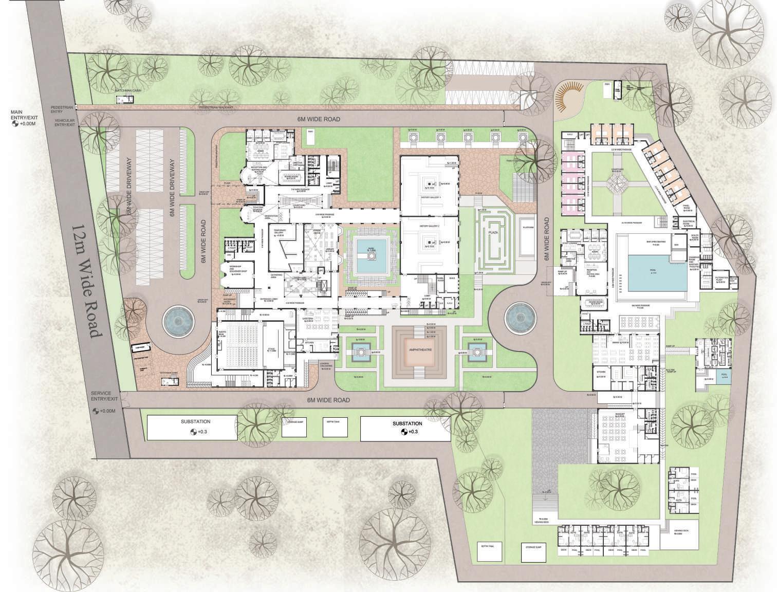


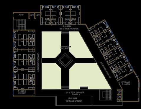
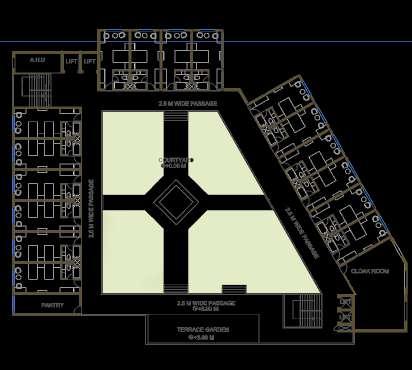


W 12m Wide Road TEMPORARY 6M WIDE ROAD 6M WIDE ROAD 6M WIDE ROAD COURTYARD MAIN ENTRY/EXIT SERVICE ENTRY/EXIT 6M WIDE DRIVEWAY +0.00M +0.00M +0.00 6M WIDE ROAD +0.00 +0.90 M ROOM SANITARY MWIDE PASS GE M WATCHMAN CABIN SUBSTATION SUBSTATION +0.3 +0.3 SEPTIK TANK FIGHTING ROOM VEHICULAR ENTRY/EXIT PEDESTRIAN ENTRY 6M WIDE DRIVEWAY SWD PIPE MAIN WATER SUPPLY MUNICIPAL SUPPLY LINE FROM UGT TO OHT SUPPLY LINE FROM RWH TO ELECTRICAL SUPPLY LINE DRAINAGE LINE TO SEPTIC TANK FROM SUBSTATION TO METER ROOM LINE TO UGT OHT(FLUSHING) OHT RWH TANK STORAGE SUMP 9M 9M 9M X 9M 6.85M 12M 5.25M 8.4M 33M X 9M GARBAGE DISPOSAL 3.0M X 6.0M 4.75M 5.5M WET RISER PIPE THK 100MM FIRE HYDRANTS LOOP SUBSTATION SEPTIC TANK FIRE HYDRANTS IC CHAMBER SWD PIPE MAIN WATER SUPPLY MUNICIPAL SUPPLY LINE FROM UGT TO OHT SUPPLY LINE FROM RWH TO ELECTRICAL SUPPLY LINE DRAINAGE LINE TO SEPTIC TANK FROM SUBSTATION TO METER ROOM LINE TO UGT OHT(FLUSHING) OHT RWH TANK STORAGE SUMP 9M X 9M 9M X 9M 6.85M X 12M 5.25M X 8.4M 33M X 9M GARBAGE DISPOSAL 3.0M 6.0M 4.75M X 5.5M WET RISER PIPE THK 100MM FIRE HYDRANTS LOOP SUBSTATION SEPTIC TANK ü FIRE HYDRANTS IC CHAMBER GULLY TRAP DRAINAGE SLOPE DIRECTION WATER METER SITE PLAN GROUND FLOOR INTERPRETATION CENTRE FIRST FLOOR PLAN TOURIST ACCOMODATION FIRST FLOOR PLAN TOURIST ACCOMODATION SECOND FLOOR PLAN SPA PLAN SUITE PLAN TWIN BEDROOM PLAN DOUBLE BEDROOM PLAN
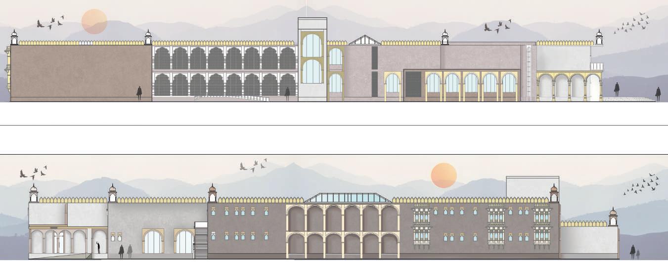

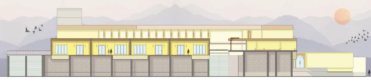
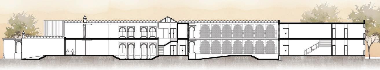

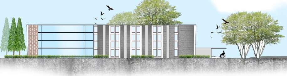
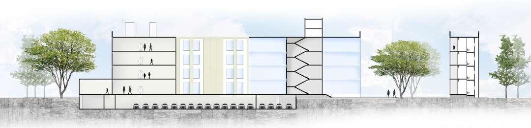
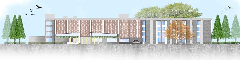
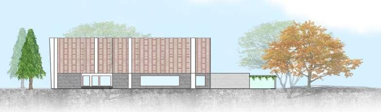
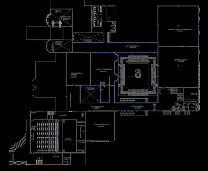
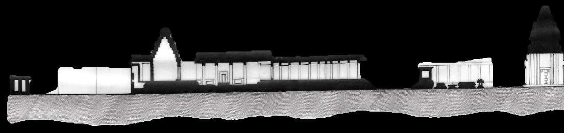
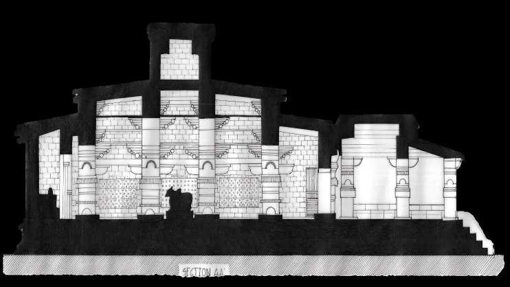
W INTERPRETATION CENTRE NORTH ELEVATION INTERPRETATION CENTRE EAST ELEVATION Gallery Jali Corridoor Library Atrium Admin Double Height reception Main Entrance Auditorium Cafeteria Service Core Library Atrium Gallery Admin TOURIST ACCOMODATION SOUTH ELEVATION Suites Rooms Suites Spa SECTION AA’ +9.00M +4.90M +0.90M +0.00M Workshop/ Souvenier shop Secondary Entry Gathering Area Courtyard Library Jali Corridoor Lobby Service Lobby 500x500 R.C.C. COLUMN 25 MM Ø COLUMN REINFORCEMENT 12 BARS 8 MM Ø LINKS AT 100 MM C/C 40 MM THK COLUMN CLEAR COVER 25 MM THK EXTERNAL PLASTER 15 THK INTERNAL PLASTER 600X300 R.C.C. BEAM 1750X1750 DROP PANEL 12 MM Ø DROP PANEL REINFORCEMENT IN BOTH DIRECTIONS 1500 1500 15 THK INTERNAL PLASTER 20 MM THK STONE TILING 1750X1750 DROP PANEL 20 MM THK SCREEDING 400 MM THK RCC FLAT SLAB 25 Ø TWO TIERED SLAB REINFORCEMENT AT 520 C/C IN BOTH DIRECTIONS 25 MM Ø COLUMN REINFORCEMENT 8 BARS 8 MM Ø LINKS AT 100 MM C/C 600X300 R.C.C. BEAM 16 MM Ø BEAM MAIN REINFORCEMENT 25 MM THK EXTERNAL PLASTER 40 MM THK COLUMN CLEAR COVER 12 MM Ø DROP PANEL REINFORCEMENT IN BOTH DIRECTIONS 25 MM THK CLEAR COVER SPAN/4=2000 SPAN/4=2000 150 100 100 100 100 100 ALUMINUM SNAP CAP BEYOND RIDGE FLASHING EPDM GLAZING GASKET TEK SCREW ALUMINUM PURLIN CLIP ALUMINUM SNAP BOTTOM INTER-SKY PURLIN CONDENSATION GUTTER BEYOND INTER-SKY RAFTER BEYOND MACHINE SCREW INTERNAL SPLICE PLATE 12MM TOUGHEND GLASS SILICONE SEAL ALUMINUM SNAP BOTTOM TEK SCREW EPDM GLAZING GASKET ALUMINUM PURLIN CLIP EPDM SETTING BLOCK SILICONE SEAL ALUMINUM SNAP CAP BEYOND INTER-SKY PURLIN W/ FIN ANCHOR ALUMINUM PLATE INTER-SKY RAFTER BEYOND SILL FLASHING GLAZING SCREW BOSS ALUMINUM SNAP CAP ALUMINUM PRESSURE CAP 12MM TOUGHEND GLASS EPDM GLAZING GASKET 1/4"-20 BOLT (8" O.C.) INTER-SKY RAFTER CONDENSATION GUTTER EPDM SETTING BLOCK EPDM GLAZING GASKET SILICONE SEAL ALUMINUM SNAP CAP BEYOND INTER-SKY SILL WEEP HOLE INTER-SKY RAFTER BEYOND ANCHOR SILL FLASHING 12MM TOUGHEND GLASS PLANTATION FINISH GRADE BACKFILL WITH EXACAVATED MATERIAL EARTH PEBBLES MULCH 50MM THICK GRASS IN OPENINGS CONCRETE PAVERS 75MM THICK CURB BEDDING COURSE 50 MM THICK STONE OPEN-GRADED BASE 100 MM THICK STONE SUBBASE 150MM THICK UNDISTURBED EARTH
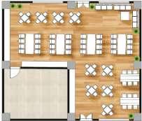
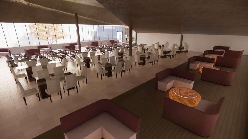
CAFETERIA
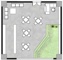
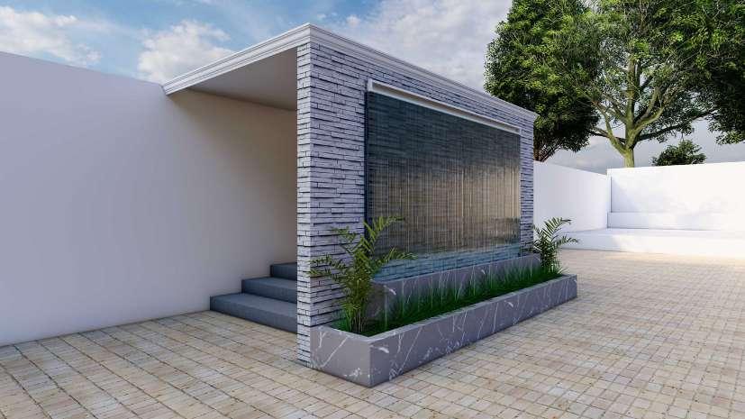
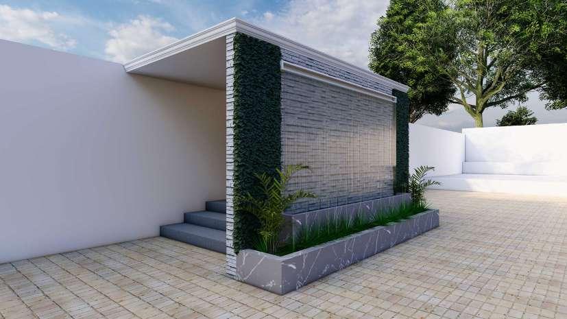
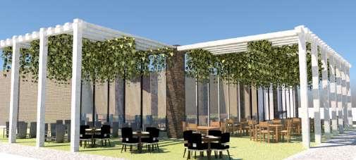
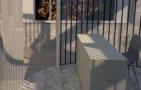
BRIEF : TO DESIGN AN INTERIOR SPACE WHICH WILL CATER TO THE REQUIREMENT OF A CAFE ALONG WITH INDOOR AS WELL AS OUTDOOR SEATING.
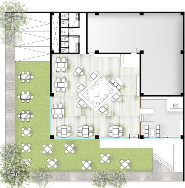
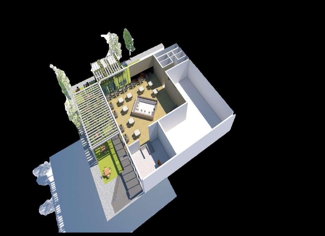
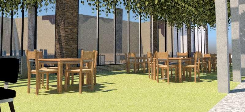
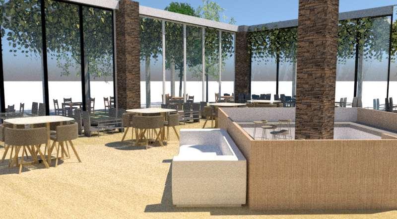
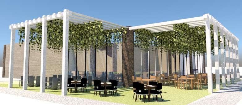
THEME: RUSTIC
CONCEPT : THE IDEA BEHIND THE THEME IS TO DESIGN A SPACE WHICH EMPHASIZES ON RUGGED NATURAL BEAUTY. THEREFORE

NATURAL MATERIALS ARE USED TO EMBRACE NATURE INSPIRED
TEXTURES, SIMPLE AND EARTHY COLOURS AND AN UNPRETENTIOUS ORGANIC WARMTH.
MATERIAL CHART
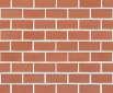
BRICK: WALL CLADDING
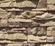
STONE: COLUMN CLADDING
GLASS: GLAZING

PVC WOOD : FLOORING

COLOUR SCHEME
MARBLE : FLOORING
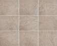


CERAMIC TILES: TOILETS
GRASS: OUTDOOR

STONE PAVERS : PATHWAY
SECTION AA’
SECTION BB’
B A’
PLAN A B’
OUTDOOR SEATING INTERIOR VIEW ISOMETRIC VIEW
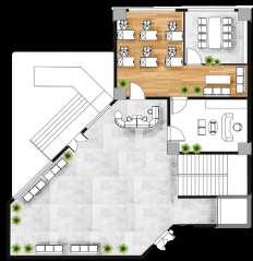
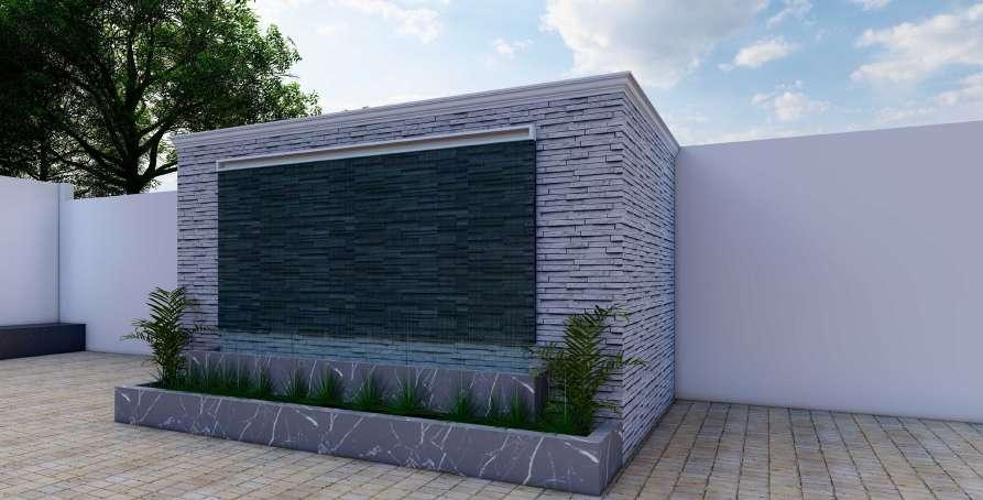
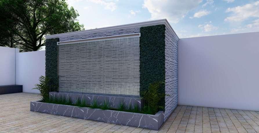
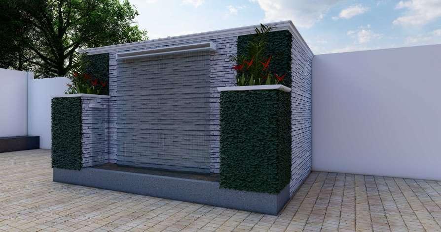
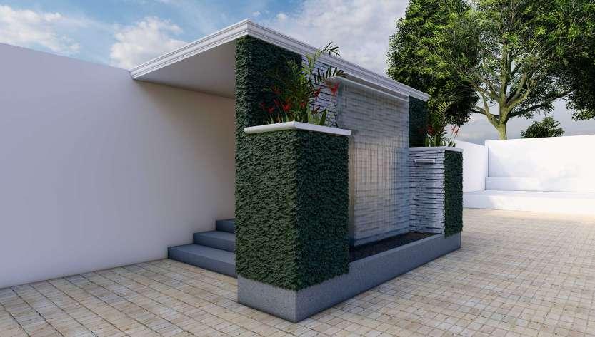
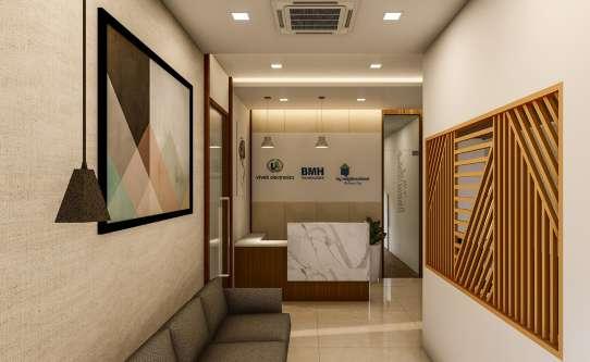
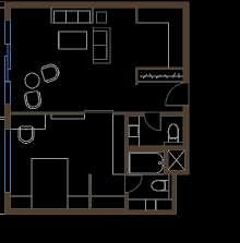
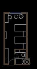
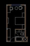
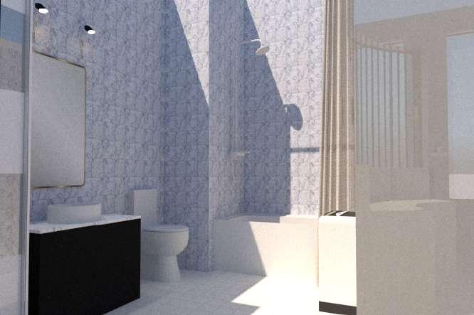
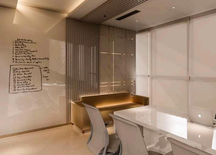
CONCEPT : TO CREATE AN ENVIRONMENT WITH MAXIMUM DAYLIGHTING AND NATURAL MATERIALS TO ENHANCE AESTHETICS AND IMPROVE CREATIVITY. THE MAIN ELEMENT IN THE DESIGN IS THE PARTITION WALL WHICH IS BUILT TO EMPHASIZE THE WORKSTATION TO SIGNIFY THE HARDWORK AND POTENTIAL OF AN ARTIST. IT ALSO BREAKS THE LINEARITY OF THE SPACE AT THE SAME TIME IS AESTHETICALLY PLEASING.


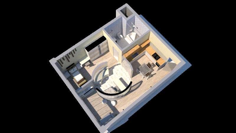
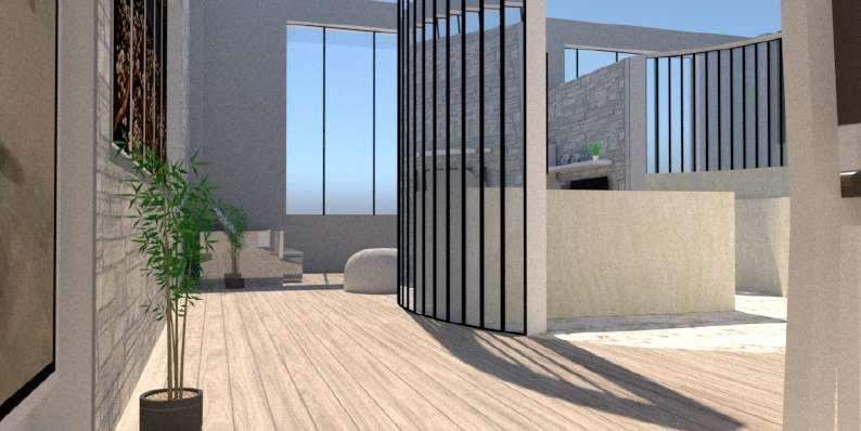
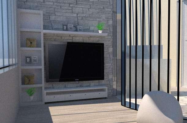
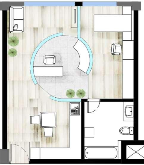

STUDIO APARTMENT
GLASS: PARTITION WALL
FAUX WOOD: FLOORINGWALL
B’ B A A’
LIVING AREA WORKSTATION
PLAN SECTION
CERAMIC TILES: BATHROOM SECTION
MATERIAL
CHART
ISOMETRIC VIEW
BATHROOM
BB’
AA’
BRIEF : TO DESIGN A STUDIO APARTMENT FOR AN ARTIST.
SECTION

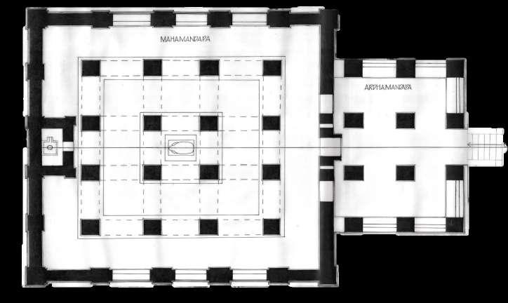
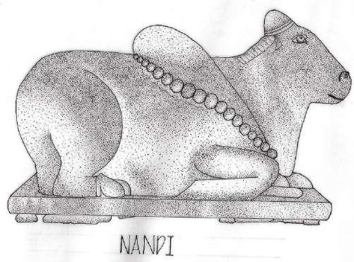
The temple shows clear signs of following early timber models, none of which have survived. This is seen for example in the construction of the roof of the mandapa. Originally dedicated to Vishnu, now the main shrine houses a Shiva Linga with a Nandi. The temple was built in a Panchayatana style, indicating a very early experiment in temple construction. The special feature of this temple is that it starts with a rectangular structure and ends with a square structure. Based on a wooden construction design, the square and rectangular plan has a steep roof, which is an adaptation of wooden styles in stone.
TEMPLE
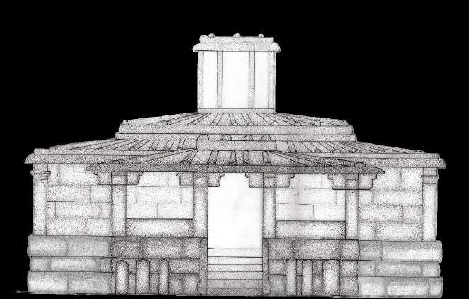
The Chalukya Shiva Temple(earlier known as Lad Khan Temple), dedicated to Shiva, is one of the oldest Hindu temples and is located in the group of monuments at Aihole in the state of Karnataka, India. Formerly dated to the 7th or 8th century, it is now dated to about the 5th century. It is located to the south of the Durga temple, Aihole.
ISOMETRIC VIEW
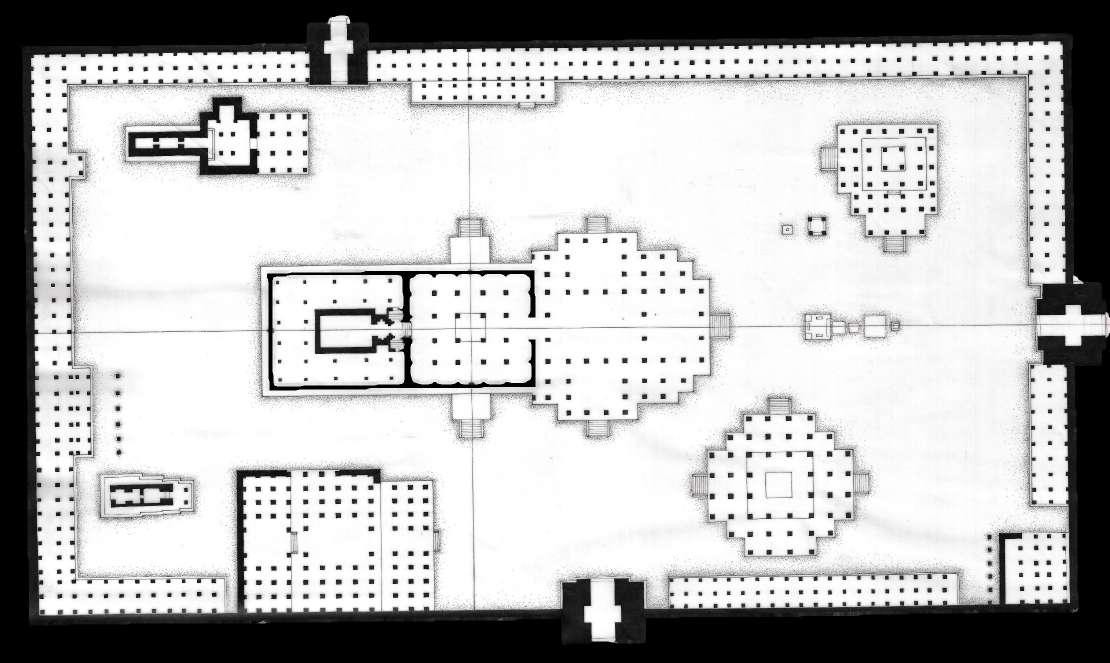
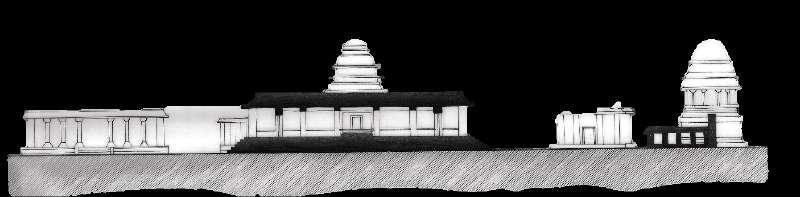
Vittala Temple is the most extravagant architectural showpiece of Hampi. The temple was originally built in the 15th century AD. The temple is built in the form of a sprawling campus with compound wall andgateway .The iconic temple has amazing stone structures such as the incomparable stone chariot and the fascinating musical pillars, towers. There are many halls, pavilions and temples located inside this campus. The Vittala Temple is presumed to be the grandest of all temples and monuments in Hampi. The temple exemplifies the immense creativity and architectural excellence possessed by the sculptors and artisans of the Vijayanagara era.
The Vittala temple is built in the Dravidian style of architecture. It has traits and features that ARE characteristicS of typical south Indian temple architecture.
LADAKHAN
ELEVATION ELEVATION
SECTION BB’
SECTION AA’
LADAKHAN TEMPLE
B B’ A A’
VITTHALA TEMPLE
PLAN
KARNATAKA DOCUMENTATION


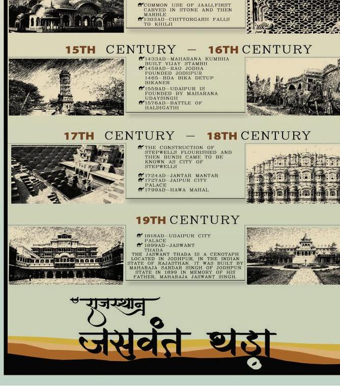
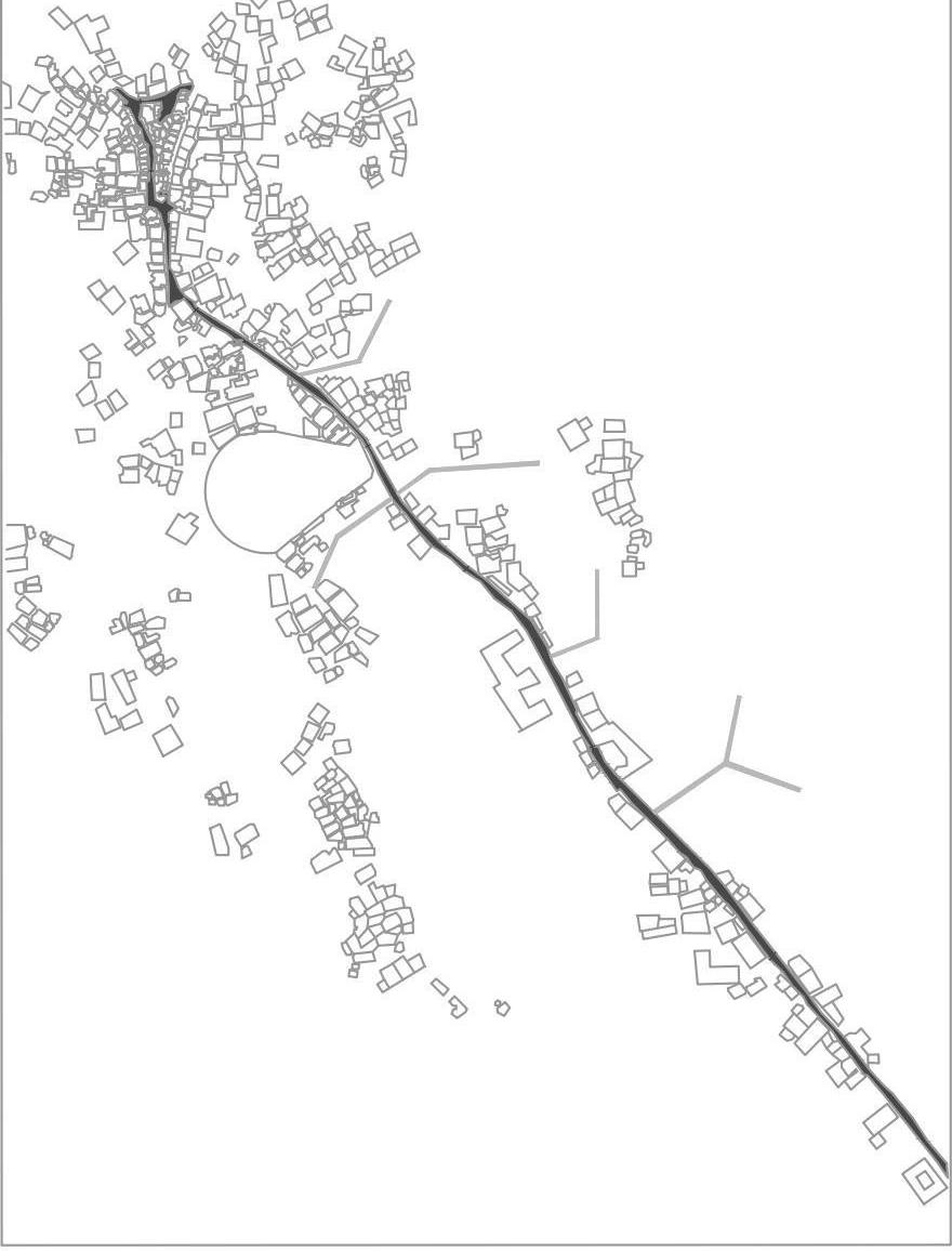
DETAILS LOCATION MAP PLAN ELEVATION ISOMETRIC VIEW ROOF PLAN SECTION ELEVATION ELEVATION PRODUCED BY AN AUTODESK STUDENT VERSION PRODUCED BY AN AUTODESK STUDENT VERSION PRODUCED BY AN AUTODESK STUDENT VERSION JASWANT THADA DOCUMENTATION
TIMELINE OF GARLI
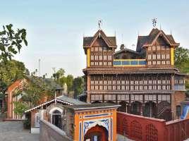
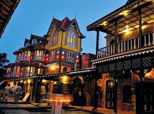
CHATEAU GARLI
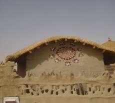
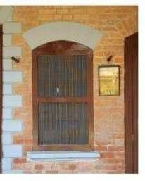
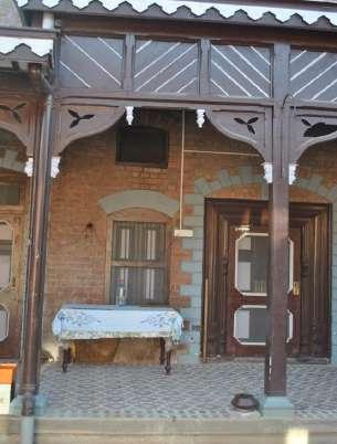
INTRO: THE OLD FASHIONED YET ATTRACTIVE HISTORIC CITIES , OR HERITAGE VILLAGES ARE REMARKABLE FOR THEIR HISTORIC ARCHITECTURE AND LOCAL CULTURE WITH ITS IMPECCABLE HERITAGE RESOURCES. INDIA IS THE MULTICULTURAL COUNTRY WITH ITS SCENIC VALLEY OF DHAUL ADHARRANGE i.e GARLI. GARLI IN HIMACHAL PRADESH IS A POPULAR HERITAGE VILLAGE, FOR ITS ANCIENT ARCHITECTURE, HERITAGE AND LOCAL CULTURE. IT HAS VARIED ARCHITECTURAL STYLE:PORTUGUESE, ITALIAN, BRITISH, KANGRA, RAJPUT ETC.
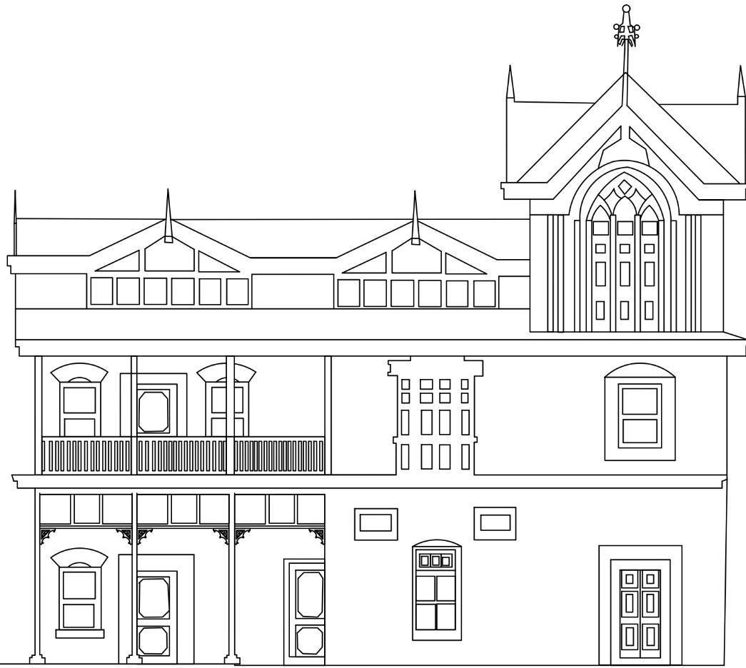
THE MAIN BUILDING IS THREE STOREY TALL BUILDING. HIGHER THAN THE HEIGHT OF THE SURROUNDING AREAS TO CREATE A SENSE OF COMPLEXITY. A COURTYARD IS LOCATED ON THE SIDE OF THE BUILDING. A SMALL DOUBLE STOREY STRUCTURE ON THE EITHER SIDE OF THE COURTYARD ISSUED AS KITCHEN.
ABOUT:
GARLI IS LOCATED IN KANGRA VALLEY. IT IS HOME OF THE FAMOUS KANGRA SCHOOL OF PAINTING.
THE KANGRA DISTRICT DERIVES ITS NAME FROM KANGRA TOWN WHICH WAS CALLED NAGARKOT IN ANCIENT TIMES.
THE SITE CHOSEN FOR GARLI LIES IN THE FOOTHILLS OF DHAULADHAR
LOCATION:
COUNTRY: INDIA
STATE: HIMACHAL
PRADESH DISTRICT: KANGRA
TEHSIL: PRAGPUR
VILLAGE: GARLI
ELEVATION: 2000FT(550)MABOVE SEA LEVEL
❑ ARCHITECTURAL CHARACTER OF GARLI IS ONE OF THE FINEST EXAMPLES OF TRADITIONAL ARCHITECTURE OF HIMACHAL PRADESH.
❑ PLANNING FEATURES AND CONSTRUCTION


TECHNIQUES HAVE BEEN HIGHLY INFLUENCED FROM MUGHAL ARCHITECTURE AND COLONIAL PRESENCE.
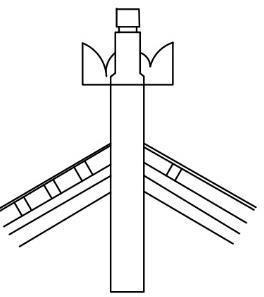
❑ GOTHIC SPIRES WITH DECORATIVE AND ORNATE FINIALS CAN BE FOUND IN PROMINENT BUILDINGS AT GARLI.
❑ THERE ARE MANY ELEGANT HAVELIS, MANSION BUILDINGS THAT ARE INTERCEPTED AMONGST MUD PLASTERED AND SLATE ROOF HOUSES WHICH LIE ALONGSIDE STREETS PAVED WITH DRESSED COBBLESTONE.
SECOND FLOOR PLAN
SECOND FLOOR CONSISTS OF 5 ROOMS ALL OF THEM BEING USED AS BEDROOMS. EACH OF THE SMALL ROOM BEING ACCESSIBLE THROUGH THE VERANDA,TWO OF THE ROOMS HAVE ACCESS THROUGH THE ROOM ITSELF THE CONCEPT WAS TO USE ONE ROOM AS MASTER-BED ROOM.
FIRST FLOOR PLAN
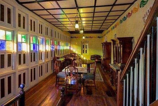
THE FIRST FLOOR CONSISTS OF FOUR BEDROOMS. THESE ROOMS ARE ACCESSED BY TWO STAIRCASES. THE MAIN STAIRCASE LEADS TO THE CORRIDOR. CORRIDOR IS BEEN USED AS A RECREATIONAL AREA TO PLAY INDOOR SPORTS. ON ONE SIDE OF THE CORRIDOR THERE ARE TWO ROOMS AND TO THE RIGHT SIDE THERE IS A SERIES OF STAINED GLASS WINDOWS GIVING ACCESS TO BEAUTIFULLY FILTERED LIGHT INSIDE THE CORRIDOR.
GROUND FLOOR PLAN
AN OPEN VERANDA AT THE ENTRANCE. TOTAL 4 ROOMS ON THE GROUND FLOOR. ENTRANCE LEADS TO DRAWING ROOM. DRAWING ROOM IS FURTHER CONNECTED TO DINING ROOM. ROOMS AT THE BACK ARE USED AS BEDROOM WITH ATTACHED STOREROOM.
THE CONCEPT OF ATTACHED STOREROOM TO BEDROOM IS INSPIRED FROM PORTUGUESE ARCHITECHTURE.
TWO STAIRCASES LEADING TO FIRST FLOOR. COURTYARD IS VISIBLE FROM BEDROOM AREA.
THE PLAN IS ORIENTED SUCH THAT THE BEDROOM AREA GETS SUNLIGHT.
KANGRA WAS FOUNDED BY KATOCH KSHATRIYA RAJPUTS OF CHANDERVANSHI LINEAGE BY KATOCHKSHATRIYA RAJPUTS OF CHAN DERVANSHI LINEAGE.
THEY HAD A STRONG HOLD WITH A FORT AND LAVISH TEMPLES
PRAGPUR WAS FOUNDED TO COMMEMORATE PRINCESS PRAG DEI. VARIOUS COMMUNITIES WERE ALLOCATED DISTINCTIVE LIVING SPACES RAKKAR, PIRSALUTI,ETC WERE SOME OF THE CLANS OF HILL SOODS


THE SOODS FOUNDED GARLI THEY BUILT VARIOUS HAVELIS, VILLAS, MOMUMENTSETC.
1806:THEGURKHA ARMY ENTERED THE GATES OF NAGARKOT 1806
1846:KANGRA WAS CAPTURED BY BRITISH
1846:KANGRA WAS CAPTURED BY BRITISH
1836:CONSTRUCTION OF BANTA RESIDENCE
1877:CONSTRUCTION OF BISHNUNIWAS
1898:CONSTRCUTION OF MOHANNIWAS
1912: CONTRUCTION OF NAURANG YATRI NIWAS
1921: CHATEAUE GARLI AFTER INDEPENDENCE KANGRA WAS MERGED IN INDIA 1948 : IT WAS PART OF PUNJAB 1966 TRANFERED TO HIMACHAL PRADESH 1997 DECLARED AS HERITAGE VILLAGE BY INDIAN GOV

M A N BU LD NG COURTYAR D KITCHEN
PLAN
ROOF PLAN SITE
LOCATION MAP
GARLI- HIMACHALPRADESH DOCUMENTATION
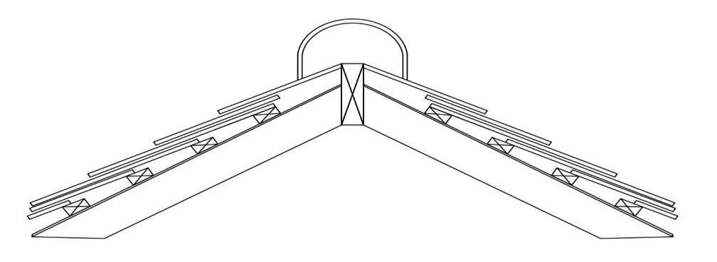
ROOFS ARE STEEPLY PITCHED, EMULATING THE PITCHED,THATCHED ROOFS USED TO DEAL WITH THE WET CLIMATE ROOFS ARE EITHER GABLED OR CROSS GABLED, NOT HIPPED ROOFS ARE CONSTRUCTED OUT OF WOODEN BEAMS FOLLOWED BY PURLINS AND RAFTERS,TOPPED BY SLATES SLATES TO ALSO WEIGHS DOWN THE STRUCTURE AGAINST STRONGWINDS.
GROUND FLOOR IN BRICK MASONRY AND COARSELY DETAILED.
A PARTIAL SCREEN OF WOOD IS PROVIDED TO SHADE THE VERANDA.
DECORATIVE EAVEBOARD TO HIGHLIGHT THE BOUNDRYFLOOR GAP.
A SERIES OF STAINED JET TIED FIRST FLOOR WITH HALF TIMBER CONSTRUCTION.
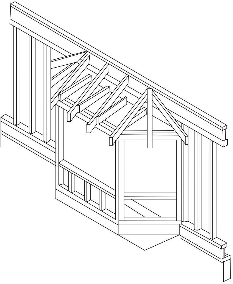
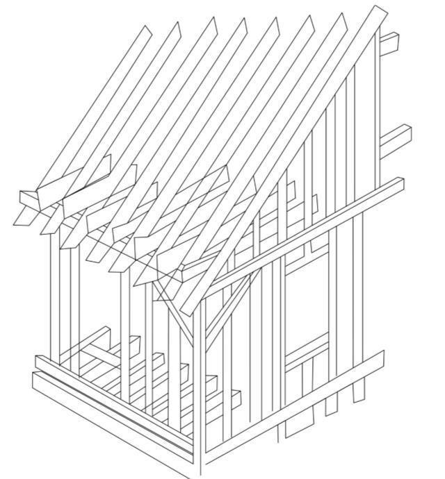
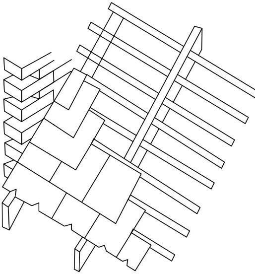
WATTLE AND DAUB TIMBER CONSTRUCTION IS DONE.
TOP FLOOR CONSISTS OF TWOGABLED ROOFS ON EITHER SIDE A CENTRAL OPEN AREA.
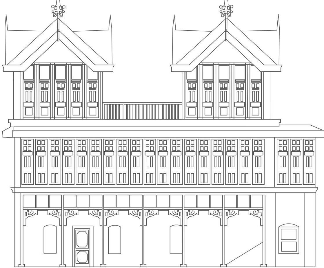
SERIES OF STAINED GLASS WINDOWS WITH INTRICATELY CARVED EAVEBOARD.
GROUND FLOOR THICKBRICK MASONRY AND COARSELY DETAILED.
A PARTIAL SCREEN OF WOOD IS PROVIDED TO SHADE THE VERANDA.
GIBBS SURROUND DOORS AND WINDOWS ON FIRSTAND GROUND FLOOR.
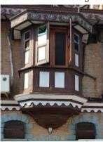
BAY WINDOW ARE INSTALLED ON SECOND FLOOR.
CROSS GABLE ROOF WITH SPIRE ON TOP WOODEN CORNICES ON GROUND FLOOR.
OCTAGONAL WINDOW:
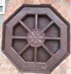
OCTAGONAL WINDOW IS USED AS A PROMINENT FEATURE IN THE BUILDING. IT IS DERIVED FROM GOTHIC ARCHITECTURE.
AN ORIEL WINDOW IS A FORM OF A BAYWINDOW WHICH PROTRUDES FROM MAIN WALL OF A BUILDING BUT DOES NOT REACH TO THE GROUND SUPPORTED BY CORBELS, BRACKETOR SIMILAR ON ORIEL WINDOW IS MOST COMMONLY FOUND PROJECTING FROM AN UPPER FLOOR BUT ITS ALSO SOMETIMES USED ON GROUND FLOOR.
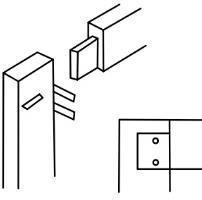

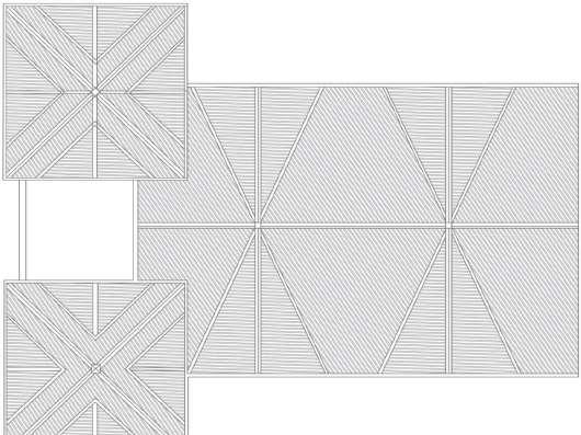
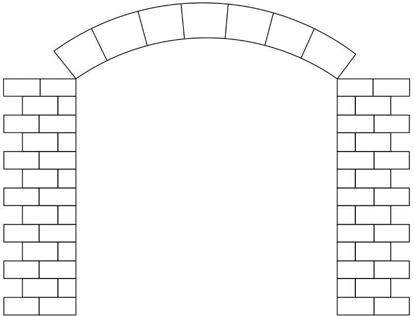
+9200MM +6200 M M +4000 MM +225 MM +9200MM +6200 M M +4000 M M +225 MM SLATE ROOF ALONG WITH RIDGE TILE FRONT ELEVATION SPIRE DETAIL MUGHAL INFLUENCE JOINERY DETAIL DEATIL C DETAIL B DETAIL A A C SIDE ELEVATION SLATE ARRANGEMENT DETAIL TIMBER ROOFING ORIEL WINDOW DETAIL ORIEL WINDOW SEGMENTED ARCH SEGMENTED ARCH GIBBS
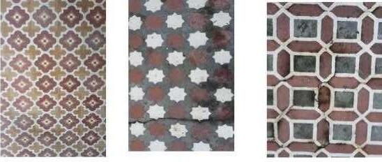
STONE TILE FLOORING IN VERANDA AND FOYER AREA
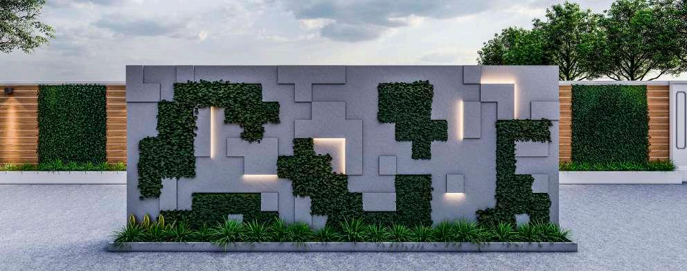
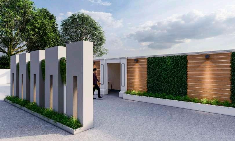
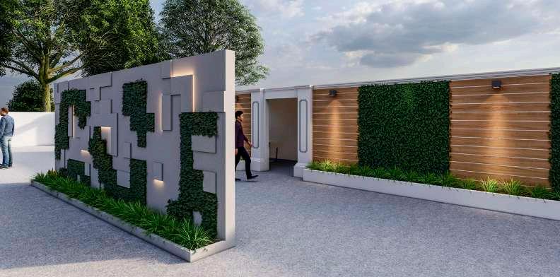
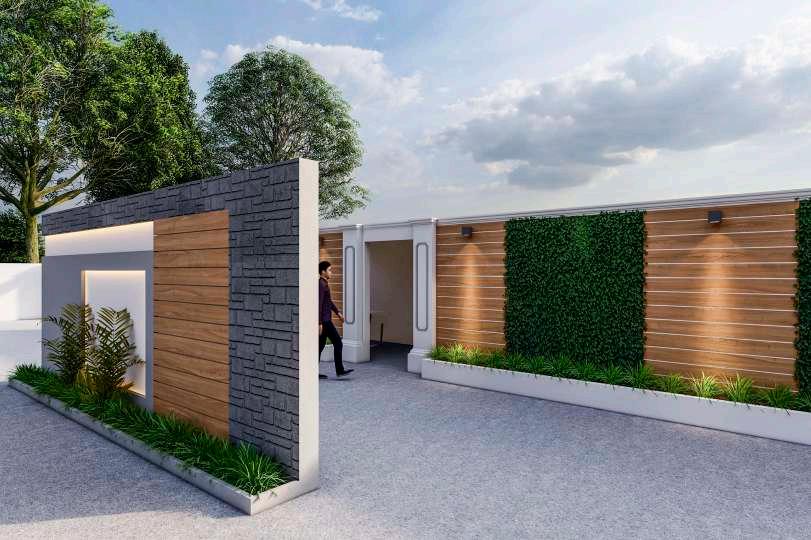
ROYAL CONNAUGHT BOAT CLUB
OFFICE SPACE INTERIOR AT WEST PORT
BHIMALE RESIDENCE
GAUTAM APARTMENTS
KLOUD Q
PROFESSIONAL PRACTICE 2021-2022
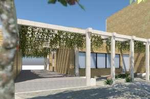
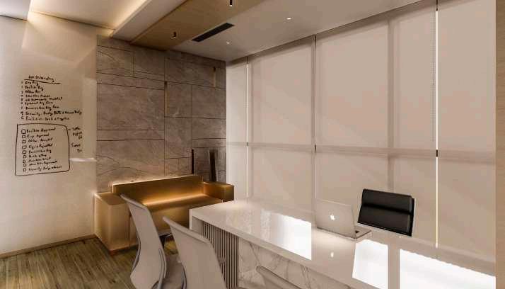
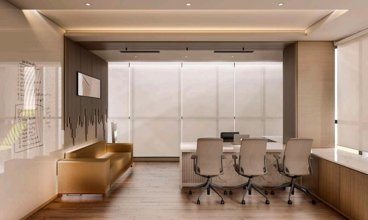
OFFICE SPACE INTERIOR AT WEST PORT
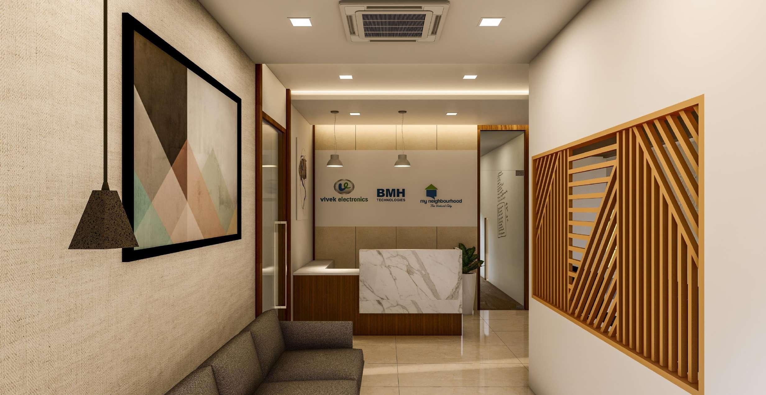
STATUS : ON GOING
SITE AREA : 130SQM (CARPET)
TYPOLOGY : COMMERCIAL INTERIOR
LOCATION : BANER, PUNE
GOOD FOR CONSTRUCTION
Notes:
1) All dimensions are in meter unless otherwise specified.
2) Do not scale the drawing. only written dimensions are to be followed.
3) For R.C.C. column and beams, please refer structural drawings.
4) Dimensions & levels shown to be verified on site before commencing work. Any discrepancies noted be brought to notice of Studio 55 prior to commencement of work.
5) Relevant MEP and landscape drawings to be read simultaneously to provide any sleeves/ cutouts as required.
Commercial Interior At West Port
GOOD FOR CONSTRUCTION
Drawing No:
Issue Date: Revision date:
Purpose of release: 03.03.2022
Project Code:
Drawn by:DK
Issued by:
Drawing : Furniture Layout
Checked by: OA
Scale: 1:100
1208, Ganga Yamuna, Flat No. 3, J.M. Road, Shivajinagar, Pune-411004
This drawing is the sole property of Studio 55 architects, Pune. Any use other than mentioned needs prior approval from Studio 55 architects, Pune, India.
Reception 10'6"X9'9" Waiting 7'6"x9'6" M Printer Pantry 12'6"x5'10" Toilet 5'0"x6'1" Entrance Accounts 15'6"x15'3" Marketing Software Head A M A M M Full height storage upto 9'6" Low height storage 2'6" ht. + Overhead storage Low height storage 2'6" ht. Low height storage 2'6" ht. Low height storage 2'6" ht. Marketing Head Accounts Head Low height 2'6" storage W W W W W W W W W W Technical Head Overhead storage 2'-6" 4' 5' 7" 5" 3' 10'-10" 2'-6" 18'6" 2' 4'-7" 2' 3'-5" 2' 1'-6" 14'8" 3'-5" 6" 3'-5" 2' 2' 3'7" 1'-6" 14'-10" 1'-6" 3'10" 3'-6" 3'-6" 3'-6" 5' 2' 2 Software 12'6"x15'9" 3'-6" 2' 2' 2' 3'-6" 3'-6" 8' 1'-6" 4'-5" 3' 3' 4'-7" 3' 9'-3" Conference 15'6"x12'6" 3'-6" 3' 1' 1'-9" 5'-3" 1'-9" 5' 1'-3" 12' 3'-6" 3'-6" 1'-8" 2' 1' 1' 2' 4' 8" 5" 4" 2'-3" 1'9" 4'-1" 6' 2 12'X18'6" Director cabin 12'X18'4" 15'-3" Full height storage upto 9' 5'-5" 2'8" 1'-6" 13'-6" 2' 1'-3" 4' 1'-9" 15'-6" 18'-5 1 2 9'-3" 7'-6" 4'-5" 5' Table 1'6"x1'6" 2'-4 1 2 6'-8 1 2 Low height storage 2'6" ht. + Overhead storage Low height 2'6" storage Low height storage 2'6" ht.
Current revision
Project
Project architects
01
GOOD FOR CONSTRUCTION
Notes:
1) All dimensions are in meter unless otherwise specified.
2) Do not scale the drawing. only written dimensions are to be followed.
3) For R.C.C. column and beams, please refer structural drawings.
4) Dimensions & levels shown to be verified on site before commencing work. Any discrepancies noted be brought to notice of Studio 55 prior to commencement of work.
5) Relevant MEP and landscape drawings to be read simultaneously to provide any sleeves/ cutouts as required.
Project
Purpose of
GOOD FOR CONSTRUCTION
07.04.2022
Project Code:
Drawn by:DK
Issued by:
Current revision
Checked by: OA
Drawing : False Ceiling Layout
Drawing No: Issue Date: Revision date: Project architects
01
Scale: 1:100
1208, Ganga Yamuna, Flat No. 3, J.M. Road, Shivajinagar, Pune-411004
This drawing is the sole property of Studio 55 architects, Pune. Any use other than mentioned needs prior approval from Studio 55 architects, Pune, India.
Reception 10'6"X6'3" Waiting 7'6"x9'6" M Printer Pantry 12'6"x5'10" Toilet 5'0" x 6' Entrance Accounts 15'6"x15'3" M Full height storage Low height storage Low height storage Marketing Head Full height storage (accounts & marketing) Low height storage Accounts Head Low height storage W W W W W W W W W W Technical Head Overhead storage Software 12'6"x15'9" Conference 15'6"x12'6" 12'X18'6" Director cabin 12'X18'4" Full height storage Marketing
release:
2'-6" 2'-6" 1'-6" 3' 4' eq 3' eq 1'-6" 2' eq 2' 4' 3' 2' 3'-3" 2'-6" 3'-0 1 2 1'-3" eq eq eq 1'-6" 1'-6" 4' 2' 2' eq 8" 4' 3'-11" 3'-11" 1'-9" 1'-9" 2'-6" 1'-9" 1'-9" 4' 4' 4'-6" 4'-6" 8" 1'-9" 4' 3'-10" 3'-6" 2'-10" eq eq 8" 1'-9" 4' 4' 8' 3'-1" 3'-11" 2' 4' 3'-1" 4' 4' 3'-1" 3'-1" 3'-5" 1'-8" eq 4'-1" eq 3'-5" eq eq eq eq 2'7" 2'7" 2'7" eq 1' eq eq 2'-10" 1'-10" 2'-5" eq eq eq eq ELECTRICAL DWG LEGEND Surface/ Concealed Light (12W) Linear Profile Light 4 ft 12" EXHAUST FAN Designer Hanging Light Grid lights Wall lights Magnetic light CCTV 6" 1'-2" 6" 1' 1'-3" 1'-3" 6" 6" 6" 1' 4'-1" 3'-5" 5'-7" 5'-7" 12'-5" eq 6'-10" eq eq 1'-9" 1' 1' eq 1' 3'-3" 3'-3" 1' 2'-5" 2'-4 1 2 3'-10" 3'-10" 3'-10" Commercial Interior At West Port
GOOD FOR CONSTRUCTION
Notes:
1) All dimensions are in meter unless otherwise specified.
2) Do not scale the drawing. only written dimensions are to be followed.
3) For R.C.C. column and beams, please refer structural drawings.
4) Dimensions & levels shown to be verified on site before commencing work. Any discrepancies noted be brought to notice of Studio 55 prior to commencement of work.
5) Relevant MEP and landscape drawings to be read simultaneously to provide any sleeves/ cutouts as required.
GOOD FOR CONSTRUCTION
Drawing No:
Issue Date: Revision date:
Purpose of release: 07.04.2022
Project Code:
Drawn by:DK
by:
Drawing : Electrical Layout
Current revision
Scale: 1:100
1208, Ganga Yamuna, Flat No. 3, J.M. Road, Shivajinagar, Pune-411004
This drawing is the sole property of Studio 55 architects, Pune. Any use other than mentioned needs prior approval from Studio 55 architects, Pune, India.
Reception 10'6"X6'3" Waiting 7'6"x9'6" M Printer Pantry 12'6"x5'10" Toilet 5'0" x 6' Entrance Accounts 15'6"x15'3" M Full height storage Low height storage Low height storage Marketing Head Full height storage (accounts & marketing) Low height storage Accounts Head Low height storage W W W W W W W W W W Technical Head Overhead storage Software 12'6"x15'9" Conference 15'6"x12'6" 12'X18'6" Director cabin 12'X18'4" Full height storage Marketing 2'-6" 2'-6" 1'-6" 3' 4' eq 3' eq 1'-6" 2' eq 2' 4' 3' 2' 3'-6" 2'-6" 3'-0 1 2 " 1'-3" 2 3 4 eq eq eq 1'-6" 1'-6" 4' 2' 2' eq 8" 4' 3'-11" 3'-11" 1'-9" 1'-9" 2'-6" 1'-9" 1'-9" 4' 4' 4'-6" 4'-6" 8" 1'-9" 4' 3'-10" 3'-6" 2'-10" eq eq 8" 1'-9" 4' 4' 8' 3'-1" 3'-11" 2' 4' 3'-1" 4' 4' 3'-1" 3'-1" 3'-5" 1'-8" eq 4'-1" eq 3'-5" eq eq eq eq 2'7" 2'7" 2'7" eq 1' eq eq 2'-10" 1'-10" 5 6 7 8 13 15a 10 18 17 16 W1 W1 W1 W1 W1 W1 W1 W1 W1 W1 W1 W1 W1 W1 W1 W1 W1 W1 15 10a 14 2'-5" eq eq eq eq 1a 6" 1'-2" 6" 1' 1'-3" 1'-3" 6" 6" 6" W1 1' 1b 1c 4'-1" 3'-5" 5'-7" 5'-7" 12'-5" eq 6'-10" eq eq 1'-9" 9 1' 1' eq 11 12 1' W1 W1 3'-6" 3'-6" 1' 2'-5" 2'-4 1 2 3'-10" 3'-10" 3'-10" W1 W1
Project architects Project Checked by: OA
01
ELECTRICAL DWG LEGEND Surface/ Concealed Light (12W) Linear Profile Light 4 ft 12" EXHAUST FAN Designer Hanging Light Grid lights Wall lights Magnetic light CCTV Commercial Interior At West Port Issued
SB noSB LocationSB Height Description 1a Reception 2'10" 3 no. switches 1 no. 6 amp plug with switch 1 telecom point 1 no. switch 1b Reception 2' 3 no. amp plugs 1 lan point 1c Reception 2'10" 1 no. switch for 3 ceiling light points 1 no. switch for 2 Hanging light points 1 no. switch for 2 cove light points 2 Conference 4'6"1 no. amp plug with switch for T.V 3 Conference 4'6"2 no. switches for 6 ceiling light points (3 Each) 2 no. switches for 4 panel lights points (2 Each) 1 no Of switch for magnetic light 4 Waiting area 4'6" 1 no. switches for 2 cove light points 3 no. switches for 6 ceiling light points(2 each) 5 Waiting area 2'1 no. amp plug with switch 6 Pantry 3'6"1 no. switch for 3 ceiling lights 2 no. 16 amp plug with switches 7 Toilet 4'6"1 no. Switch for ceiling light point 1 no. Switch for Exhaust fan 8 Toilet 4'6"1 no. switch for wall light point 1 no. of 6 amp plug with switch 9 Software 3'10"1 no. switch for 2 ceiling light point 2 no. switches for 4 panel light points (2 Each) 10 Marketing Head 2'10"2 no. switches for 4 ceiling light points (2 Each) 10a Accounts Head 2'10"2 no. switches for 4 ceiling light points (2 Each) 11 Software 3'6"1 no. switch for 2 ceiling light point 2 no. switches for 6 panel light points (3 Each) 12 Software 2'10" 2 no. 6 amp plug with switches for printer 1 telecom point 13 Technical Head 4'6" 1 no. switch for 2 panel light points 1 no. switch for 3 panel light point 14 Director Cabin 4'6" 1 no. Switches for ceiling light points 3 no. Switches for ceiling light points (2 Each) 15a Director Cabin 2' 3 no. amp plug points 1 no. LAN point 15 Director Cabin 2'10" Two way switch for ceiling light points 2 no. switches 1 no. telecom point 1 no. 6 amp plug with switch 1 no. switch point 16 Director Cabin 4'6"1 no. amp plug with switch 1 no. LAN point 17 Director Cabin 2'10" 2 no. amp plugs with switches 18 Director Cabin 2'10"1 no. of 6 amp plug with switch W1 2' 2 switches 3 Plug points 1 no. telephone point 1 no. of LAN point Electrical Schedule
GOOD FOR CONSTRUCTION
Notes:
1) All dimensions are in meter unless otherwise specified.
2) Do not scale the drawing. only written dimensions are to be followed.
3) For R.C.C. column and beams, please refer structural drawings.
4) Dimensions & levels shown to be verified on site before commencing work. Any discrepancies noted be brought to notice of Studio 55 prior to commencement of work.
5) Relevant MEP and landscape drawings to be read simultaneously to provide any sleeves/ cutouts as required.
Project
Commercial Interior At West Port
GOOD FOR CONSTRUCTION
W Current revision
Drawing No:
Purpose of release: 15.03.2022
Project Code:
Drawn by:DK
Issued by:
Drawing : Wall elevations
Issue Date: Revision date: Project architects
01
Checked by: OA
Scale: 1:100
1208, Ganga Yamuna, Flat No. 3, J.M. Road, Shivajinagar, Pune-411004
This drawing is the sole property of Studio 55 architects, Pune. Any use other than mentioned needs prior approval from Studio 55 architects, Pune, India.
Elevation - D 3" thk skirting Openable shutter made of 12mm thk ply and finished with 1mm thk regular grey laminate. TV as per selection Tile as per selection Shutter Shutter Shutter Shutter Shutter Shutter 1 2"thk Counter top made of plywood and finished with regular white laminate as per selection Desk made of 18mm thk ply and finished with laminte as per selection 3" 2'-1" 1" 1" 1" 2'-1" 2'-6" 1" 2'-1" 6'-7" 2'-6" Shelf Shelf Shelf Shelf Elevation A Openable shutter made of 12mm thk plywood finished with 1mm thk grey laminate 3" thk skirting Openable shutter made of 12mm thk plywood finished with 1mm thk orange laminate finish/ duco as per selection Laminate as per selection Glass partition of 12mm thk toughened glass with aluminium framing (refer seperate drawings) 1 "thk Counter top made of plywood and finished with regular white laminate as per selection SS Finish handles as per selection 3" 2" 2'-1" 2" 3" 2'-7" 7'-1" 2" 1" 2'5" 1" 1'-11" 4' 1" 1'-5" 6'-11" 2" 2' 5' 5' 4'-11" Elevation - B 3" thk skirting Openable shutter made of 12mm thk plywood finished with 1mm thk laminate finish/ duco as per selection Open Shelf Shelf Shelf 3'-6" 3" 5'-3" 1" 1'8" 5" 1'-6" 10" 9" 1'-11" 2'-5" 2'-8" 2'-8" 3'-10" 3" Low height storage 2'6" ht. Low height storage 2'6" ht. Full height storage 4" Director cabin 12'X18'4" W W M M M M Marketing Head Low height storage 2'6" ht. + Overhead storage Low height storage 2'6"ht. Elevation A Marketing Head cabin Openable shutter made of 12mm thk ply and finished with 1mm thk laminate as per selection Openable shutter made of 12mm thk ply and finished with 1mm thk regular grey laminate as per selection 1 "thk Counter top made of plywood and finished with regular white laminate as per selection 3" thk skirting 2'-6" 3" 1' 3'-5" 2'-6" 1" 1" 2'1" 3" W Director Cabin
GOOD FOR CONSTRUCTION
Notes:
1) All dimensions are in meter unless otherwise specified.
2) Do not scale the drawing. only written dimensions are to be followed.
3) For R.C.C. column and beams, please refer structural drawings.
4) Dimensions & levels shown to be verified on site before commencing work. Any discrepancies noted be brought to notice of Studio 55 prior to commencement of work.
5) Relevant MEP and landscape drawings to be read simultaneously to provide any sleeves/ cutouts as required.
Project
Commercial Interior At West Port
GOOD FOR CONSTRUCTION
Drawing No:
Purpose of release: 15.03.2022
Project Code:
Drawn by:DK
Issued by:
Drawing : Wall elevations
Issue Date: Revision date: Project architects
Current revision
Checked by: OA
Scale: 1:100
1208, Ganga Yamuna, Flat No. 3, J.M. Road, Shivajinagar, Pune-411004
This drawing is the sole property of Studio 55 architects, Pune. Any use other than mentioned needs prior approval from Studio 55 architects, Pune, India.
01
Full height storage Technical Head Overhead storage 4'-7" 18'6" 2' 3'-5" 2' 2' 3'-5" 1'-6" 4' 1'-3" 6" 14'8" 12' Workstation 12'X18'6" Elevation - B Openable shutter made of 12mm thk plywood finished with 1mm thk laminate finish/ duco as per selection 3" 2'-6" 1" 4' 1" 2'-1" 9' Shelf Shelf Shelf Elevation - C Drawer Drawer Drawer Drawer Drawer Drawer 3" thk skirting Openable shutter made of 12mm thk plywood finished with 1mm thk orange laminate finish/ duco as per selection Openable shutter made of 12mm thk ply and finished with 1mm thk regular grey laminate. SS Finish handles as per selection 2'-6" 1' 2' 3'-6" 2" 2'4" 9' 7' 2"3" 2'5" 4' 1" 2' 1'-5" W 4'-7" 3' 9'-3" 3'-6" Full height storage upto 9' 1'-6" 13'-6" 2'-6" Conference 15'6"x12'6" 3'10" Elevation A Storage shutter made of 18mm thk ply and finished with 1mm thk regular laminate as per selection 1 1 "thk Counter top made of plywood and finished with regular white laminate as per selection Drawer Drawer 1" thk plywood panelling made of 12mm thk ply and finished with 4mm thk veneer as per selection Wall paint as per selection Drawers made up of 18mm thk and 12mm thk plywood and finished with 1mm thk regular white finish laminate. 3" thk skirting 3'-6" 1'-5" 8" 1'-10" 2" 1" Shelf Shelf Shelf Elevation - B Openable shutter made of 12mm thk plywood finished with 1mm thk laminate finish as per selection Tile as per selection 1" thk plywood panelling made of 12mm thk ply and finished with 4mm thk veneer as per selection 3" 3'10'' 2" 2'5" 1'5" 1" 1'-5" eq eq 3'-7" 1'9" 1'9" eq

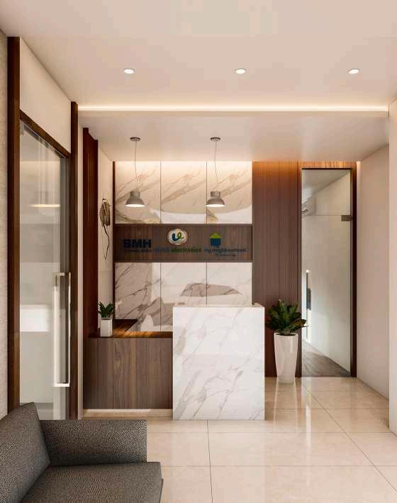
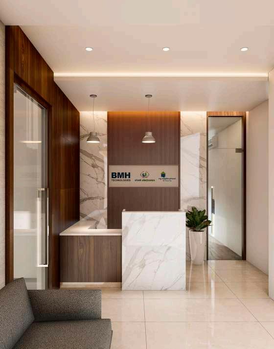
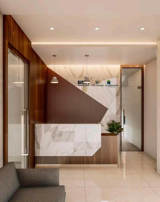
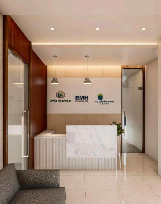
reception optional views OPTION 1 OPTION 3 OPTION 2 OPTION 4
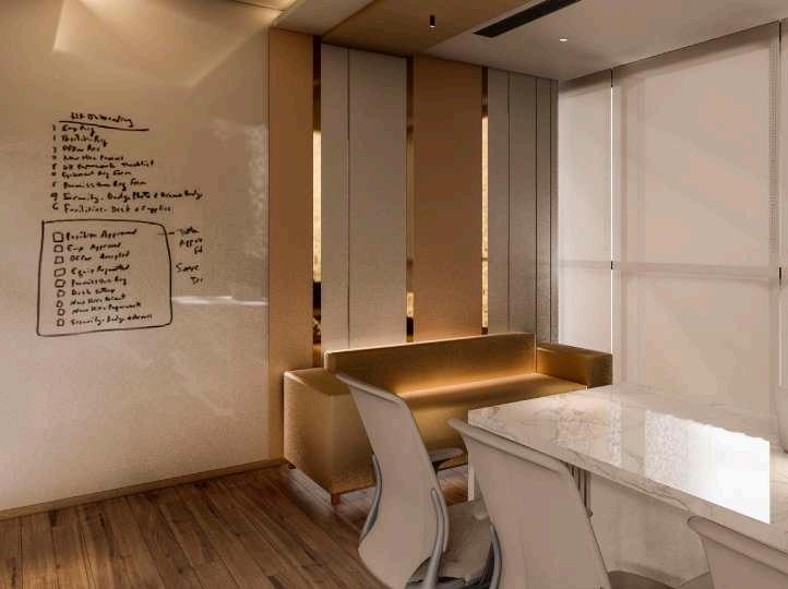
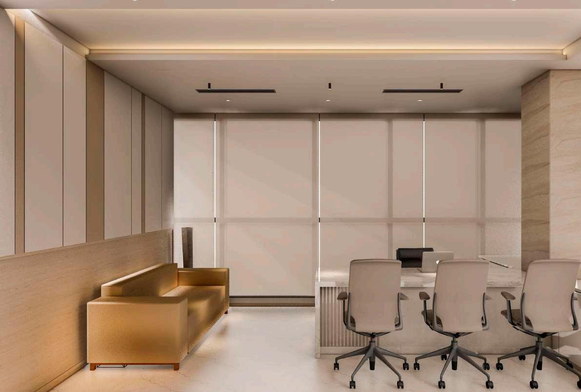
DIRECTOR CABIN optional views OPTION 1 OPTION 4 VIEW 1 OPTION 3 OPTION 4 OPTION 5 OPTION 2
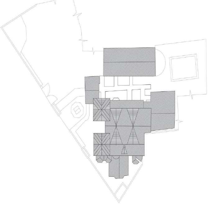
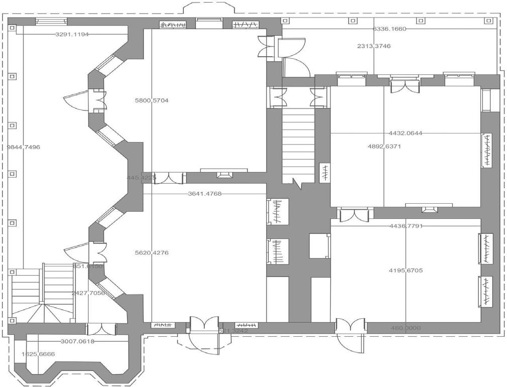
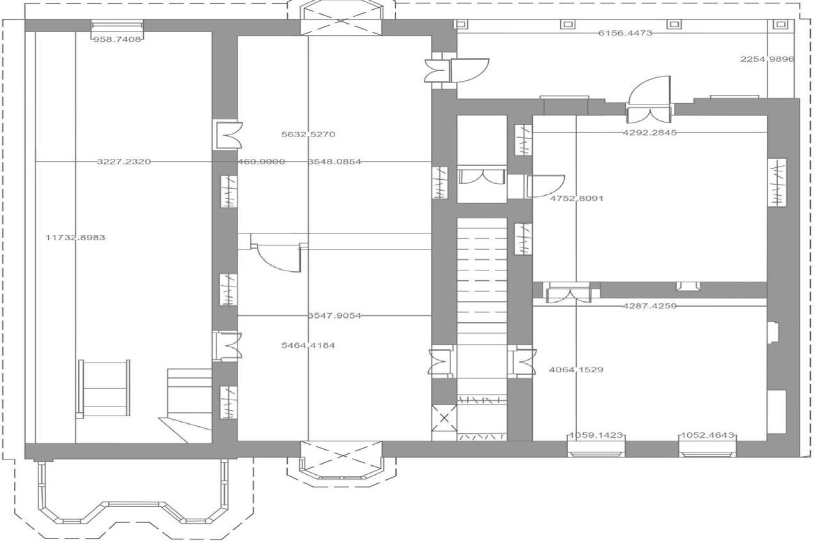
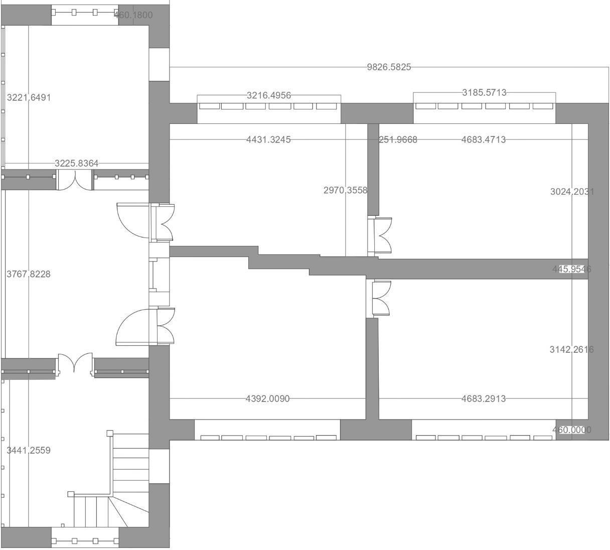
BHIMALE RESIDENCE
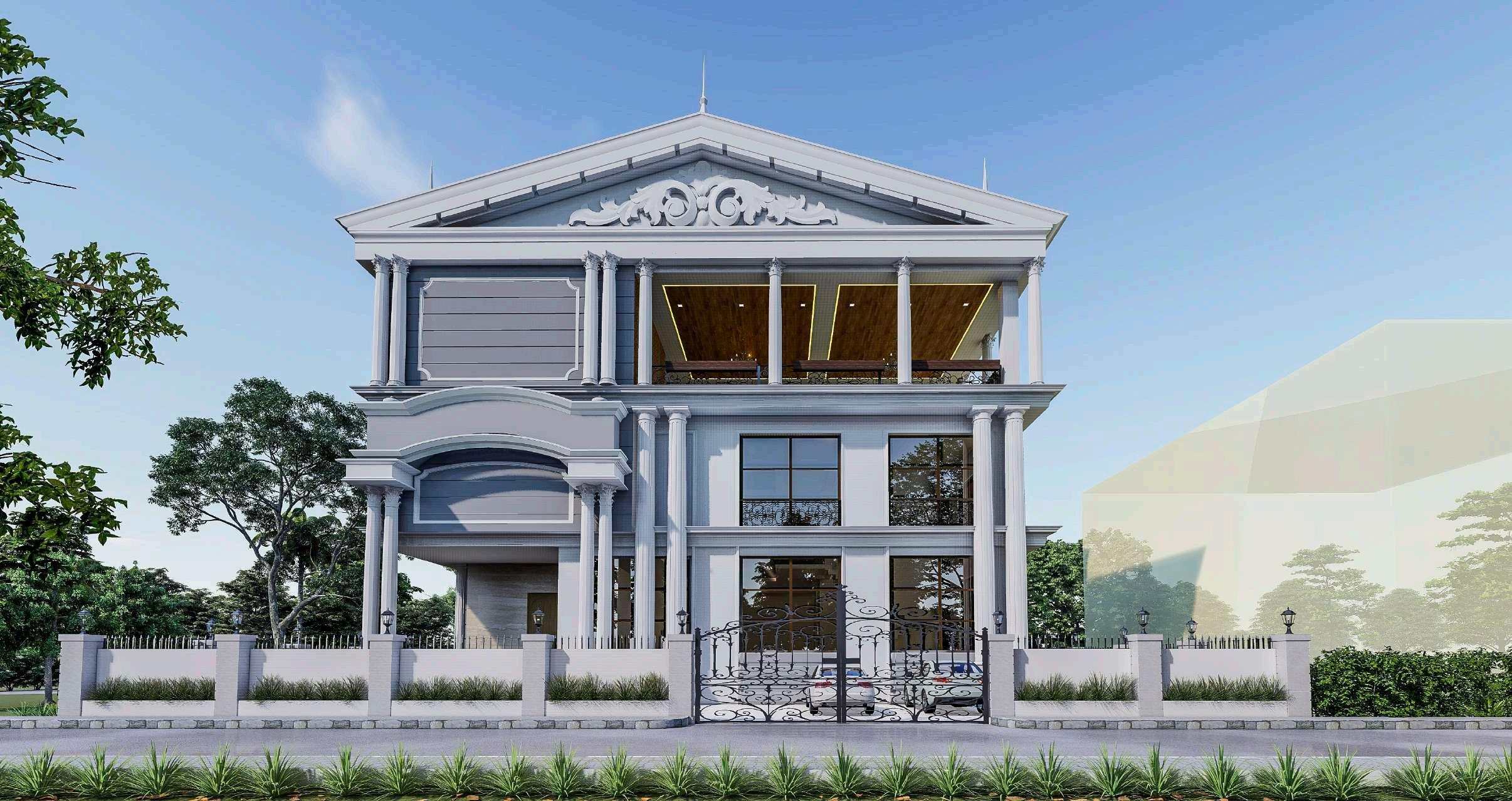
STATUS : ON GOING
SITE AREA : 797.48 SQM
BUILT-UP AREA : 921.63SQM
TYPOLOGY : RESIDENTIAL BUNGALOW
LOCATION : PUNE
1.
Good for construction
General Notes:
2.
All dimensions are in MM unless otherwise specified. Do not scale the drawing. Only written dimensions are to be followed
3.
4.
For R.C.C. columns and beams, please refer structural drawings Dimensions & levels shown to be verified on site before commencing work. Any discrepancies noted be brought to notice of Studio 55 prior to commencement of work.
5. 6.
Relevant MEP and landscape drawings to be read simultaneously to provide any sleeves/ cutouts as required.
Bathroom, dry balcony and terrace slab sunks are 200 MM deep unless otherwise specified.
Dimensions & levels shown are structural unless other specified. 7.
This drawing should be read in reference with R.C.C. drawing for 8. column and footing.
This drawing should be reference with drawing No. - 9. 2005.Building setout plan.01.
PURPOSE OF RELEASE
Drawing No:
Issue Date:
20.04.2022
Drawn by: DK
Ground Floor Plan
Project:
Bhimale Residence
Good for construction
Scale: 1:100
Floor:
Drawing
2005.Toilet details -
Toilet Details
Project Architects
Phone: 020 25512505
www.studio55.in
1205/8, "Ganga Yamuna" Building Flat No.3, First floor, Off. J.M. Road, Shivaji Nagar, Pune India-411004
This drawing is the sole property of Studio 55 architects, Pune. Any use other than mentioned needs prior approval from Studio 55 architects, Pune, India.
PARENT'S TOILETGROUND FLOOR ELEVATION C PLAN V2 A C B D
Fixture Chart Sr.no Fixture Code Height Make 1 Diverter KUP-CHR-35065NKPM 2 Bath-Spout SPJ-CHR-35463PM 3 Health-FaucetBib Cock ALD-CHR-573 4 Control Plate JCP-CHR-352415 5 Bottle Trap ALD-CHR-769L300X190 6 Wall Hung WC SLS-WHT-6953BIUFSM 7 Basin Mixer KUP-CHR-35011BPM 750 1200 550 1025 350 450 800 Jaquar Jaquar Jaquar Jaquar Jaquar Jaquar Jaquar SUNK 750 1200 450 800 1025 2100 3380 600 600 1000 1800 850 1200 3050 3335 550 1200 1116 465 40 450 1116 370 520 1200 200 558 558 550 150 100 50 100 50 1000 1200 150 GROUND FLOOR COMMON TOILET A C B D ELEVATION C PLAN 2660 900 1575 800 450 400 400 50 900 450 520 370 450 2100 1025 750 360 1200 800 3050 465 450 975 550 V2 50 100 900 873 230X500 230X500 03 500X230 04 05 230X500 230X500 09 230X500 230X500 230X500 230X500 19 230X500 22 230X500 230X500 230X500 230X350 14 700X230 15
1
Good for construction
General Notes:
1.
2.
All dimensions are in MM unless otherwise specified. Do not scale the drawing. Only written dimensions are to be followed
3.
For R.C.C. columns and beams, please refer structural drawings
4.
Dimensions & levels shown to be verified on site before commencing work. Any discrepancies noted be brought to notice of Studio 55 prior to commencement of work.
5.
Relevant MEP and landscape drawings to be read simultaneously to provide any sleeves/ cutouts as required.
6.
Bathroom, dry balcony and terrace slab sunks are 200 MM deep unless otherwise specified.
7.
Dimensions & levels shown are structural unless other specified.
This drawing should be read in reference with R.C.C. drawing for 8. column and footing.
This drawing should be reference with drawing No. - 9. 2005.Building setout plan.01.
PURPOSE OF RELEASE
Drawing No:
Issue Date:
Project:
Bhimale Residence
Good for construction
2
5 Bottle Trap ALD-CHR-769L300X190
20.04.2022
Drawn by: DK
Scale: 1:100
Floor:
Drawing
2005.Toilet details -
Toilet Details
Project Architects
Phone: 020 25512505
www.studio55.in
1205/8, "Ganga Yamuna" Building Flat No.3, First floor, Off. J.M. Road, Shivaji Nagar, Pune , India-411004
This drawing is the sole property of Studio 55 architects, Pune. Any use other than mentioned needs prior approval from Studio 55 architects, Pune, India.
SUNK SERVENT'S TOILET PLAN
Fixture Chart Sr.no Fixture Code Height Make
Diverter KUP-CHR-35065NKPM
Bath-Spout
Health-Faucet
Bib Cock
SPJ-CHR-35463PM 3
-
ALD-CHR-573
4 Control Plate JCP-CHR-352415
Basin Mixer KUP-CHR-35011BPM 750 1200 550 1025 350 450 800 Jaquar Jaquar Jaquar Jaquar Jaquar Jaquar Jaquar 500 eq eq 453 760 413 525 928 450 800 750 450 1025 3050 3050 1206 450 1200 40 275 195 465 1200 800 40 250 200 465 3050 465 150 150 1220 1100 451 230X500 230X500 04 05 230X500 500X230 230X500 230X500 08 230X500 230X500 230X500 230X500 230X500 230X500 20 22 21 230X500 230X500 230X500 230X700 700X230 1350 1350 Ground Floor Plan
6 Wall Hung WC SLS-WHT-6953BIUFSM 7
Good for construction
General Notes:
1.
All dimensions are in MM unless otherwise specified.
2.
Do not scale the drawing. Only written dimensions are to be followed
3.
For R.C.C. columns and beams, please refer structural drawings
4.
Dimensions & levels shown to be verified on site before commencing work. Any discrepancies noted be brought to notice of Studio 55 prior to commencement of work.
5.
Relevant MEP and landscape drawings to be read simultaneously to provide any sleeves/ cutouts as required.
6.
Bathroom, dry balcony and terrace slab sunks are 200 MM deep unless otherwise specified.
7.
Dimensions & levels shown are structural unless other specified.
This drawing should be read in reference with R.C.C. drawing for 8. column and footing.
This drawing should be reference with drawing No. - 9. 2005.Building setout plan.01.
PURPOSE OF RELEASE
Drawing No:
Issue Date:
20.04.2022
Drawn by: DK
Project:
Bhimale Residence
Good for construction
Scale: 1:100
Floor:
Drawing :
2005.Toilet details -
Toilet Details
Project Architects
Phone: 020 25512505
www.studio55.in
1205/8, "Ganga Yamuna" Building Flat No.3, First floor, Off. J.M. Road, Shivaji Nagar, Pune India-411004
This drawing is the sole property of Studio 55 architects, Pune. Any use other than mentioned needs prior approval from Studio 55 architects, Pune, India.
BATH TUB FIRST FLOOR DAUGHTER TOILET PLAN A C B D ELEVATION B
Fixture Chart Sr.no Fixture Code Height Make 1 Diverter KUP-CHR-35065NKPM 2 Bath-Spout SPJ-CHR-35463PM 3 Health-FaucetBib Cock ALD-CHR-573 4 Control Plate JCP-CHR-352415 5 Bottle Trap ALD-CHR-769L300X190 6 Wall Hung WC SLS-WHT-6953BIUFSM 7 Basin Mixer KUP-CHR-35011BPM 750 1200 550 1025 350 450 800 Jaquar Jaquar Jaquar Jaquar Jaquar Jaquar Jaquar SUNK 900 1920 550 900 900 900 4000 450 450 370 1236 750 1200 2100 800 450 1025 550 1200 3050 465 250 900 200 520 200 150 50 eq eq 50 100 150 SUNK FIRST FLOOR COMMON TOILET PLAN A C B D ELEVATION D 1790 2670 750 1200 2100 500 1025 800 1226 eq eq 450 550 1200 40 250 3050 465 200 750 900 50 956 50 100 18 230X500 20 230X500 230X500 230X500 09 230X500 15 700X230 230X500 500X230 04 230X500 500X230 230X500 230X500 230X700 700X230 250X250
First Floor Plan
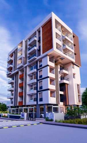
GAUTAM APARTMENTS
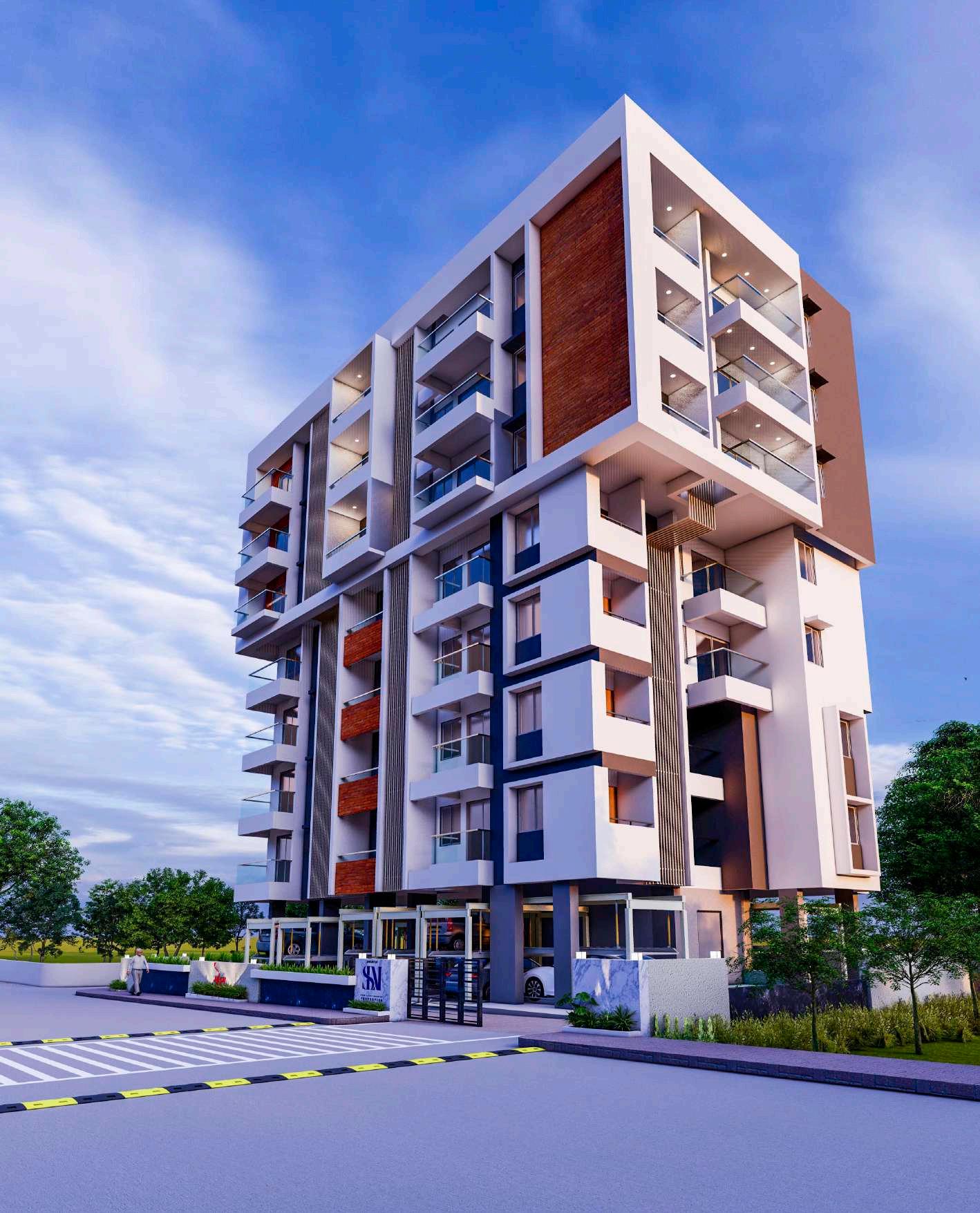
STATUS : ON GOING
SITE AREA : 526.62 SQM
BUILT-UP AREA : 1684.02SQM
TYPOLOGY : REDEVELOPMENT RESIDENTIAL BUILDING
STILT + 7 FLOORS
LOCATION : PUNE
GOOD FOR CONSTRUCTION
1. All dimensions are in MM unless otherwise specified.
2. For R.C.C. columns, beams, slabs; please refer structural drawing.
3. Dimensions & levels shown to be verified on site before commencing work. Any discrepancies noted be brought to notice of Studio 55 prior to commencement of work.
4. Relevant MEP,structural drawings and landscape drawings to be read simultaneously to provide any sleeves/ cutouts as required.
5. Bathroom, dry balcony and terrace slab sunks are 150 MM deep unless otherwise specified.
6. Dimensions & levels shown are structural unless other specified.
7. Do not scale the drawing. Only written dimensions to be followed.
pipes shown in plan are indicative & for showing their positions only. Refer MEP consultant's drawing for the same.
0.10m thk. BB masonry
Type
1205/8 "Ganga Yamuna" Building Flat No.3, First floor, Off. J.M. Road Shivaji Nagar, Pune-411004 This drawing is the sole property of Studio 55 architects, Pune. Any use other than mentioned needs prior approval from Studio 55 architects, Pune, India. Notes Stilt floor plan Drawn by: DKStilt floor plan Additional
Service
Drawing Floor: 1:75 Scale: Project code: 30/ 03 /2022 Issue Date Revision Date Current Revision Drawing No. Purpose of release: GOOD FOR CONSTRUCTION Project Name- GAUTAM APARTMENTS
note:
0.15m thk. BB masonry 0.23m thk. R.C.C. Pardi Size Size Schedule of openings Description Type Description D D1 D2 SD1 SD2 V 1.00 X 2.35 0.90 X 2.35 0.75 X 2.35 2.75 2.35 1.50X 2.35 0.60 1.15 45 MM. TK. FLUSH DOOR 45 MM. TK. FLUSH DOOR 45 MM. TK. FLUSH DOOR ALUMINUM SLIDING DOOR ALUMINUM SLIDING DOOR GLASS LOUVERED VENTILATOR. W1 1.50 X 1.50 0.20m thk. BB masonry Wall Hatch Legend ALUMINUM SLIDING WINDOW. SD3 SD4 SD5 1.65X 2.35 2.45X 2.35 1.70X 2.35 ALUMINUM SLIDING DOOR ALUMINUM SLIDING DOOR ALUMINUM SLIDING DOOR SD6 2.30X 2.35 ALUMINUM SLIDING DOOR N 1.15 X 1.50 Proposed redevelopment of Gautam Apartments at Salisbury Park, Sr. no. 585, Pune ALUMINUM SLIDING WINDOW. W 0.00 1.00 3.00 5.00 8.00 10.00 L1 L3 L2 C17 300 x 1100 C16 300 x 750 C15 300 x 600 C7 1000 x 300 C13 300 x 1100 C8 300x700 C9 800 x 300 C11 600 x 300 C10 800 x 300 C5 380 x 500 C6 600 x 300 C4 300 x 800 C3 300 x 800 C2 800 x 300 C1 850 x 300 C12 800 x 300 C18 1000 x 300 C19 600 x 300 C14 300 x 1100 UP CCTV 1.20 x 3.70 1,2 3,4 5,6 7,8 9,10 11,12 13,14 17,18 15,16 19,20 21,22 Lift Shaft Lobby 2.05 x 2.05 4.95 x 3.75 23 Seating Name plate Seating Letter box Temple VDP Op02 VDP Op01 W +0.450 M 1 2 3 4 5 7 8 9 16 14 10 11 12 13 14 17 18 19 20 2550 3700 1200 150 1200 350 685 1500 1025 1500 1 2 3 1550 2950 4920 250 250 3850 450 1500 12450 7700 Top/ Bottom Chajja @ 19950 Slab LVL 600 600 LD Lift opening as per manual TREAD= 0.25 RISER = 0.15 450 2050 2050 850 6 15
STILT FLOOR PLAN (SCALE=1:75)
pipes shown in plan are indicative & for showing their positions only. Refer MEP consultant's drawing for the same.
(SCALE=1:75)
1050 1.70X1.25 Toilet V Sunk200 mm Sunk150mm 600 C19 600 x 200 1200 500 1800 150mm thk 200mm thk Brick masonry Brick masonry DETAIL 2 DETAIL 1 DETAIL 3 W1 450 450 100mm thk Brick masonry Duct 2.80 x 0.5 V Beam Line 200mm thk Brick masonry 100 200 C16 200 x 750 300 500 200 Beam Line 200mm thk Brick masonry DETAIL 4 DETAIL 6 DETAIL 5 C17 200 x1100 Beam Line 200mm thk Brick masonry 150mm thk Brick masonry A A B B C C D D E E D D 0.10m thk. BB masonry Type 1. All dimensions are in MM unless otherwise specified. 2. For R.C.C. columns, beams, slabs;
structural drawing. 3. Dimensions &
of Studio 55
work. 4. Relevant MEP,structural drawings
landscape drawings to
simultaneously
sleeves/ cutouts as required. 5. Bathroom, dry balcony and terrace slab sunks are 150 MM deep unless otherwise specified. 6. Dimensions & levels shown are structural unless other specified. 7. Do not scale the drawing. Only written dimensions to be followed. 1205/8 "Ganga Yamuna" Building Flat No.3, First floor, Off. J.M. Road Shivaji Nagar, Pune-411004 This drawing is the sole property of Studio 55 architects, Pune. Any use other than mentioned needs prior approval from Studio 55 architects, Pune, India. Notes First floor plan Drawn by: DKFirst floor Additional
Drawing Floor: 1:75 Scale: Project code: 31/ 03 /2022 Issue Date Revision Date Current Revision Drawing No. Purpose of release: GOOD FOR CONSTRUCTION Project Name- GAUTAM APARTMENTS GOOD FOR CONSTRUCTION 0.15m thk. BB masonry 0.23m thk. R.C.C. Pardi Size Size Schedule of openings Description Type Description D D1 D2 SD1 SD2 1.00 2.10 0.90 X 2.10 0.75 2.10 2.75 X 2.10 1.50X 2.10 0.60 X 0.90 45 MM. TK. FLUSH DOOR 45 MM. TK. FLUSH DOOR 45 MM. TK. FLUSH DOOR ALUMINUM SLIDING DOOR ALUMINUM SLIDING DOOR GLASS LOUVERED VENTILATOR. W1 W2 W3 W4 W5 W6 W7 1.50 X 1.50 2.40 X 1.50 1.50 1.50 1.35 X 0.90 1.05 X 1.50 0.90 X 0.90 0.80 X 1.50 0.20m thk. BB masonry Wall Hatch Legend ALUMINUM SLIDING WINDOW. ALUMINUM SLIDING WINDOW. ALUMINUM SLIDING WINDOW. ALUMINUM SLIDING WINDOW. ALUMINUM FIXED WINDOW. ALUMINUM FIXED WINDOW. SD3 SD4 SD5 1.65X 2.10 2.45X 2.10 1.75X 2.10 ALUMINUM SLIDING DOOR ALUMINUM SLIDING DOOR ALUMINUM SLIDING DOOR SD6 2.30X 2.10 ALUMINUM SLIDING DOOR N 0.75 X 1.50 Proposed redevelopment of Gautam Apartments at Salisbury Park, Sr. no. 585, Pune ALUMINUM SLIDING WINDOW. ALUMINUM FIXED WINDOW. W 0.00 1.00 3.00 5.00 8.00 10.00 LW1 C17 200 x1100 C16 200 x 750 C15 200 x 600 C7 1000 x 200 C13 200 x 1100 C8 200x700 C9 800 x 200 C11 600 x 200 C10 800 x 200 C5 300 x 500 C6 600 x 200 C4 200 x 800 C3 200 x 800 C2 800 x 200 C1 850 x 200 C12 800 x 200 C18 1000 x 200 C19 600 x 200 C14 200 x 1100 LW3 LW2 900 700 2300 700 1950 800 3150 300 1200 525 1050 600 900 600 150 850 23 Sitout 2.95 X 1.25 1ST FLOOR PLAN 25 26 UP 19 D2 D1 D2 D1 D2 D1 D D D2 LD SD5 D2 D1 D1 D2 D2 Flat 102 Flat 101 D D2 600 2750 eq 1600 eq 2300 1350 600 3050 750 Sink 3100 650 600 300 2300 900 550 600 600 1700 150 2750 250 2550 525 1200 5250 600 600 650 250 1950 500 1800 2470 550 2000 775 775 1700 200 TREAD= 0.250 RISER = 0.164 22 24 28 27 20 16 29 18 17 15 Sunk-250mm 800 SD3 SD6 W4 W8 W6 V W7 W2 V W5 800 800 2050 Sunk-150mm 100 Sunk-250mm Sunk-250 mm Sunk-250mm 200 450 1200 Sunk 250 mm Beam projection 1300 3 BHK 2 BHK Beam Beam SD1 2500 SD2 SD4 1950 V V 2000 V V W1 W3 2050 T.O.C. level= +4.50 DETAIL 6 DETAIL 1 Lift opening as per manual DETAIL 2 DETAIL 4 DETAIL 5 DETAIL 3 350 500 400 Sunk-150mm Sunk-150mm Sunk-150mm Sunk-150mm 150 2750 Refer seprate Details for 100x50 mm box section details for duct closer. 100mm thick concrete pardi 300mm high 100mm thick concrete pardi 800mm high . eq eq eq eq 500 Refer Seperate Details for Glass railing Refer Seperate Details for Glass railing Refer Seperate Details for Glass railing Refer seprate Details for 100x50 mm box section details for duct closer. Refer Seperate Details for Glass railing 1150 550 eq eq 150x150mm Cut out for R.W. line Refer Seperate Details for Glass railing 300 750 1650 600 3150 600 350 Chajja Projection 1200 1500 1000 300 100 500 200
please refer
levels shown to be verified on site before commencing work. Any discrepancies noted be brought to notice
prior to commencement of
and
be read
to provide any
note: Service
21 1000 1000 600 Refer Seperate details for Glass railing 650 Refer seprate Details for 100x50 mm box section details for duct closer. Refer seprate Details for 100x50 mm box section details for duct closer. 30 31 32 D D B B W8 0.75 X 0.9 ALUMINUM FIXED WINDOW. 3100 4550 eq eq Bedroom 03 6.11 X 3.10 Toilet 1.35 X 2.10 Toilet 1.35 X 2.10 Duct 2.85 x 0.5 Dry Balcony 2.75 x 1.25 Duct 1.30 x 2.10 Kitchen 2.75 X 3.10 Living/Dinning 7.30 X 3.45 Balcony 2.0 X 0.9 Sitout 1.60 X 3.35 Bedroom 02 3.90 x 3.75 Bedroom 01 3.65 X 3.75 Toilet 1.35 X 2.30 Toilet 1.70X1.25 Toilet 1.60X1.20 Toilet 1.45 X 2.15 Sitout 1.25 X 2.80 Sitout 1.75 x 1.05 Duct 1.35 x 0.5 Lobby 2.55 X1.55 LIFT SHAFT 2.05 X 2.05 Living/Dinning 4.00 X 3.70 Office -01 4.95 X 4.10 Bedroom 01 3.10 X 3.45 Bedroom 02 2.60 X 3.90 Kitchen 2.70 X 2.55 Sitout 0.9 X 2.45 Dry Balcony 1.1 X 1.7 Sunk150mm Sunk-250mm Top/ Bottom Chajja @ 1ST Slab LVL Top/ Bottom Chajja @ 1ST Slab LVL Top/ Bottom Chajja @ 1ST Slab LVL
slab sunks are 150 MM deep unless otherwise specified.
6. Dimensions & levels shown are structural unless other specified.
7. Do not scale the drawing. Only written dimensions to be followed.
0.00 1.00 3.00 5.00 8.00 10.00 600 200 150 150 150mm thk Brick masonry 200mm thk Brick masonry 200 W1 100mm thk Brick masonry 115 450 600 200 200 600 300 150 100 D2 200 600 150 100 750 Beam 150 mm Sunk 100mm Slab(S6) 200mm thk Brick masonry Beam Line C16 Duct 0.5x1.25 V 900 1200 250 1200 900 2100 SunkSunkBeam 600 2950 Slab LVL depth 250mm 150mm SECTION BB SECTION AA SECTION CC SECTION DD SECTION FF SECTION EE 100mm Slab(S6) LW1 C17 200 x1100 C16 200 x 750 C15 200 x 600 C7 1000 x 200 C13 200 x 1100 C8 200x700 C9 800 x 200 C11 600 x 200 C10 800 x 200 C5 300 x 500 C6 600 x 200 C4 200 x 800 C3 200 x 800 C2 800 x 200 C1 850 x 200 C12 800 x 200 C18 1000 x 200 C19 600 x 200 C14 200 x 1100 LW3 LW2 900 700 2300 700 1950 800 3150 300 1200 eq 1400 600 900 600 150 850 43 Sitout 2.95 X 1.25 45 46 UP 35 D2 D1 D2 D1 D2 D1 D D D2 LD SD5 D2 D1 D1 D2 D2 Flat 102 Flat 101 D D2 600 2750 350 1600 350 2300 600 3050 750 Sink 3100 650 600 300 2300 900 550 600 600 1700 150 2750 250 2550 eq 1200 5250 600 600 650 250 1950 500 1800 2470 550 2000 775 775 1700 200 TREAD= 0.250 RISER = 0.164 40 41 44 48 47 36 49 34 33 Sunk-250mm 800 SD3 SD6 W4 W8 W6 V W7 W2 V W5 800 800 2050 Sunk-150mm 100 Sunk-250mm Sunk-250mm Sunk-250mm 200 450 400 300 1200 750 Beam projection 1300 3 BHK 2 BHK Duct 0.5x 1.25 Beam SD1 2500 SD2 SD4 1950 V V 2000 V V W1 W3 2050 T.O.C. level= +4.50 DETAIL 6 DETAIL 1 Lift opening as per manual DETAIL 2 DETAIL 4 DETAIL 5 DETAIL 3 350 500 400 Sunk-150mm Sunk-150mm SunkSunk-150mm 150mm Sunk-150mm 200 2750 Refer seprate Details for 100x50 mm box section details for duct closer. 100mm thick concrete pardi 300mm high . 100mm thick concrete pardi 800mm high . eq eq eq eq 500 Refer Seperate Details for Glass railing Refer Seperate Details for Glass railing Refer Seperate Details for Glass railing Refer seprate Details for 100x50 mm box section details for duct closer. Refer Seperate Details for Glass railing 1150 550 eq eq 150x150mm Cut out for R.W. line 150 150 Refer Seperate Details for Glass railing 300 750 1650 600 3150 600 350 Chajja Projection 1200 1500 1300 1000 300 100 500 200
Sunk-150mm Refer Seperate Details for Glass railing 37 38 39 42 50 0.10m thk. BB masonry Type 1. All dimensions are in MM unless otherwise specified. 2. For R.C.C. columns, beams, slabs; please refer structural drawing. 3. Dimensions & levels shown to be verified on site before commencing work. Any discrepancies noted be brought to notice of Studio 55 prior to commencement of work. 4. Relevant MEP,structural drawings and landscape drawings to be read simultaneously to provide any sleeves/ cutouts as required. 5. Bathroom, dry balcony and terrace
2ND FLOOR PLAN (SCALE=1:75)
1205/8 "Ganga Yamuna" Building Flat No.3, First floor, Off. J.M. Road Shivaji Nagar, Pune-411004 This drawing is the sole property of Studio 55 architects, Pune. Any use other than mentioned needs prior approval from Studio 55 architects, Pune, India. Notes First floor plan Drawn by: DKFirst floor Additional note: Service pipes
Drawing Floor: 1:75 Scale: Project code: 04/ 04 /2022 Issue Date Revision Date Current Revision Drawing No. Purpose of release: GOOD FOR CONSTRUCTION Project Name- GAUTAM APARTMENTS
0.15m thk. BB masonry 0.23m thk. R.C.C. Pardi Size Size Schedule of openings Description Type Description D1 D2 SD1 SD2 V 1.00 X 2.10 0.90 2.10 0.75 X 2.10 2.75 X 2.10 1.50X 2.10 0.60 X 0.90 45 MM. TK. FLUSH DOOR 45 MM. TK. FLUSH DOOR 45 MM. TK. FLUSH DOOR ALUMINUM SLIDING DOOR ALUMINUM SLIDING DOOR GLASS LOUVERED VENTILATOR. W1 W2 W3 W4 W5 W6 W7 1.50 X 1.50 2.40 X 1.50 1.50 X 1.50 1.35 X 0.90 1.05 X 1.50 0.90 0.90 0.80 X 1.50 0.20m thk. BB masonry Wall Hatch Legend ALUMINUM SLIDING WINDOW. ALUMINUM SLIDING WINDOW. ALUMINUM SLIDING WINDOW. ALUMINUM SLIDING WINDOW. ALUMINUM FIXED WINDOW. ALUMINUM FIXED WINDOW. SD3 SD4 SD5 1.65X 2.10 2.45X 2.10 1.75X 2.10 ALUMINUM SLIDING DOOR ALUMINUM SLIDING DOOR ALUMINUM SLIDING DOOR SD6 2.30X 2.10 ALUMINUM SLIDING DOOR N 0.75 X 1.50 Proposed redevelopment of Gautam Apartments at Salisbury Park, Sr. no. 585, Pune ALUMINUM SLIDING WINDOW. ALUMINUM FIXED WINDOW. W W8 0.75 X 0.9 ALUMINUM FIXED WINDOW.
Top/ Bottom Chajja @ 1ST Slab LVL Top/ Bottom Chajja @ 1ST Slab LVL LIFT SHAFT 2.05 X 2.05 Bedroom 03 6.11 X 3.10 Toilet 1.35 X 2.10 Toilet 1.35 X 2.10 Dry Balcony 2.75 x 1.20 Kitchen 2.75 X 3.10 Living/Dinning 7.30 X 3.45 Sitout 1.60 X 3.35 Bedroom 02 3.90 x 3.75 Bedroom 01 3.65 X 3.75 Toilet 1.45 X 2.15 Sitout 1.25 X 2.80 Sitout 1.75 x 1.05 Duct 1.35 x 0.5 Duct 2.80 x 0.5 Duct 1.30 x 2.10 Sunk 250 mm Balcony 2.0 X 0.9 Toilet 1.35 X 2.30 Toilet 1.70X1.25 Toilet 1.60X1.20 Living/Dinning 4.00 X 3.70 Office -01 4.95 X 4.10 Bedroom 01 3.10 X 3.45 Bedroom 02 2.60 X 3.90 Kitchen 2.70 X 2.55 Dry Balcony 1.1 X 1.7 Sunk150mm Sunk-250mm Sitout 1.15 X 2.45 Lobby 2.55 X1.55 Second floor Second floor
shown in plan are indicative & for showing their positions only. Refer MEP consultant's drawing for the same.
GOOD FOR CONSTRUCTION
Top/ Bottom Chajja @ 1ST Slab LVL
1. All dimensions are in MM unless otherwise specified.
2. For R.C.C. columns, beams, slabs; please refer structural drawing.
3. Dimensions & levels shown to be verified on site before commencing work. Any discrepancies noted be brought to notice of Studio 55 prior to commencement of work.
4. Relevant MEP,structural drawings and landscape drawings to be read simultaneously to provide any sleeves/ cutouts as required.
5. Bathroom, dry balcony and terrace slab sunks are 150 MM deep unless otherwise specified.
6. Dimensions & levels shown are structural unless other specified.
7. Do not scale the drawing. Only written dimensions to be followed.
D2 C17 200 x 1000 C16 200 x 650 C15 200 x 530 C7 900 x 200 C13 200 x 1000 C8 200x600 C9 700 x 200 C11 530 x 200 C10 700 x 200 C5 300 x 500 C6 530 x 200 C4 200 x 700 C3 200 x 700 C2 700 x 200 C1 750 x 200 C12 700 x 200 C18 900 x 200 C19 530 x 200 C14 200 x 1000 LW1 LW3 LW2 UP D1 D1 D2 D2 D D1 D2 D1 D2 D2 D2 SD1 D1 D1 LD Flat 302,402 Flat 301,401 D V V V V V 750 2200 300 750 550 2150 200 eq 2100 2550 1800 900 1600 200 1200 150 2550 60 61 62 63 64 57 56 55 54 53 52 51 65 66 600 3100 1600 6200 375 375 2300 600 600 900 3050 2600 600 1700 2750 300 600 1950 500 1950 350 3900 655 2000 450 1200 2000 500 500 350 1550 400 2150 350 2600 eq 1150 200 300 2470 600 700 5250 1200 3100 2300 400 1500 2450 eq 900 Lift opening as per manual T.O.C. level= +10.4 Sunk-250mm Sunk-250mm 800 Sunk-250mm 1400 Sunk-150mm Sunk-150mm 200 1950 750 550 1800 1700 3 BHK 2 BHK W1 W7 W5 W4 W10 W9 600 850 Sunk-150mm 600 Sunk-150mm 2050 2050 Sunk-150mm Sunk-150mm Sunk-150mm Sunk-150mm Sunk-150mm 0.10m thk. BB masonry
1205/8 "Ganga Yamuna" Building Flat No.3, First floor, Off. J.M. Road Shivaji Nagar, Pune-411004 This drawing is the sole property of Studio 55 architects, Pune. Any use other than mentioned needs prior approval from Studio 55 architects, Pune, India. Notes Floor plan Drawn by: DKThird floor & Forth floor plan Additional note: Service pipes shown in plan are indicative & for showing their positions only. Refer MEP consultant's drawing for the same. Drawing Floor: 1:75 Scale: Project code: 04/ 04/2022 Issue Date Revision Date Current Revision Drawing No. Purpose of release: GOOD FOR CONSTRUCTION Project Name- GAUTAM APARTMENTS
0.15m thk. BB masonry 0.23m thk. R.C.C. Pardi 0.20m thk. BB masonry Wall Hatch Legend N Proposed redevelopment of Gautam Apartments at Salisbury Park, Sr. no. 585, Pune 0.00 1.00 3.00 5.00 8.00 10.00 3RD & 4TH FLOOR PLAN (SCALE=1:75) Beam projection 200 2750 Refer seprate Details for 100x50 mm box section details for duct closer. 100mm thick concrete pardi 800mm high . Refer Seperate Details for Glass railing 1500 1150 300 500 200 Refer Seperate Details for Glass railing Refer Seperate Details for Glass railing Refer Seperate Details for Glass railing Refer seprate Details for 100x50 mm box section details for duct closer. Beam Refer Seperate Details for Glass railing Refer Seperate Details for Glass railing 150x150mm Cut out for R.W. line 150 150 100 100mm thick concrete pardi 300mm high Refer Seperate Details for Glass railing 58 59 67 68 3150 1200 450 Refer seprate Details for 100x50 mm box section details for duct closer. 1200 eq eq eq eq 600 1300 eq W8 SD6 SD2 SD3 SD5 SD3 SD7 W6 Type Size Size Description Type Description D D1 D2 SD1 SD2 1.00 X 2.10 0.90 X 2.10 0.75 X 2.10 2.75 X 2.10 1.50X 2.10 0.60 X 0.90 45 MM. TK. FLUSH DOOR 45 MM. TK. FLUSH DOOR 45 MM. TK. FLUSH DOOR ALUMINUM SLIDING DOOR ALUMINUM SLIDING DOOR GLASS LOUVERED VENTILATOR. W1 W2 W3 W4 W5 W6 W7 1.50 X 1.50 2.40 X 1.50 1.50 1.50 1.35 X 0.90 1.05 X 1.50 0.90 X 0.90 0.80 X 1.50 ALUMINUM SLIDING WINDOW. ALUMINUM SLIDING WINDOW. ALUMINUM SLIDING WINDOW. ALUMINUM SLIDING WINDOW. ALUMINUM FIXED WINDOW. ALUMINUM FIXED WINDOW. SD3 SD4 SD5 1.65X 2.10 2.45X 2.10 1.75X 2.10 ALUMINUM SLIDING DOOR ALUMINUM SLIDING DOOR ALUMINUM SLIDING DOOR SD6 2.30X 2.10 ALUMINUM SLIDING DOOR 0.75 X 1.50 ALUMINUM SLIDING WINDOW. ALUMINUM FIXED WINDOW. W W8 0.75 X 0.90 ALUMINUM FIXED WINDOW. W9 0.60X 1.50 ALUMINUM FIXED WINDOW. W10 ALUMINUM FIXED WINDOW. 0.90 X 1.50 Schedule of openings LIFT SHAFT 2.05 X 2.05 Sitout 2.95 X 1.25 Sunk-250mm Bedroom 03 6.11 X 3.10 Toilet 1.35 X 2.10 Toilet 1.35 X 2.10 Dry Balcony 2.75 x 1.20 Kitchen 2.75 X 3.10 Living/Dinning 7.30 X 3.45 Sitout 1.70 X 3.35 Bedroom 02 3.90 x 3.75 Bedroom 01 3.65 X 3.75 Toilet 1.45 X 2.15 Sitout 1.25 X 2.80 Sitout 1.75 x 1.05 Duct 1.30 x 2.10 Balcony 2.0 X 0.9 Toilet 1.35 X 2.30 Toilet 1.50 x 1.85 Living/Dinning 5.20 x 3.70 Bedroom 01 3.10 X 3.45 Bedroom 03 2.60 X 3.65 Kitchen 2.70 X 2.85 Dry Balcony 1.1 X 1.7 Sitout 1.25 x 2.30 Lobby 2.55 X1.55 Bedroom 02 3.30 x 2.90 Balcony 2.15 x 1.10 Sunk-250mm Duct 2.80 x 0.5 Duct 1.35 x 0.5 Top/ Bottom Chajja @ 3RD/4TH Slab LVL Top/ Bottom Chajja @ 3RD/4TH Slab LVL Top/ Bottom Chajja @ 3RD/4TH Slab LVL Top/ Bottom Chajja @ 3RD/4TH Slab LVL DETAIL 7 DETAIL 8 DETAIL 9 200 900 W4 300 C18 900 x 200 C19 530 x 200 200 mm thk Brick masonry G G DETAIL 7 300 600 150 2250 1200 200 mm thk Brick masonry W4 400 W9 C6 530 x 200 850 600 600 900 2100 450 200 mm thk Brick masonry Chajja Slab SD1 525 Sunk-150mm 150 150 Sitout 1.70 X 3.35 525 Railing Beam 600 200 150 450 300 600 150 mm Sunk SECTION GG H H I DETAIL 8 SECTION HH DETAIL 9 SECTION II
GOOD FOR CONSTRUCTION
2. For R.C.C. columns, beams, slabs; please refer structural drawing.
3. Dimensions & levels shown to be verified on site before commencing work. Any discrepancies noted be brought to notice of Studio 55 prior to commencement of work.
4. Relevant MEP,structural drawings and landscape drawings to be read simultaneously to provide any sleeves/ cutouts as required.
5. Bathroom, dry balcony and terrace slab sunks are 150 MM
deep unless otherwise specified.
6. Dimensions & levels shown are structural unless other specified.
Additional
masonry
1205/8 "Ganga Yamuna" Building Flat No.3, First floor, Off. J.M. Road Shivaji Nagar, Pune-411004 UP D1 D Notes Fifth floor plan Drawn by: DKFifth floor
N Proposed redevelopment of 3 BHK Gautam Apartments at Salisbury Park, Sr. no. 585, Pune Refer Seperate Details for Glass railing 93 400 C17 200 x 1000 C16 200 x 650 C15 200 x 530 C7 900 x 200 C13 200 x 1000 C8 200x600 C9 700 x 200 C11 530 x 200 C10 700 x 200 C5 300 x 500 C6 530 x 200 C4 200 x 700 C3 200 x 700 C2 700 x 200 C1 750 x 200 C12 700 x 200 C18 900 x 200 C19 530 x 200 C14 200 x 1000 LW1 LW3 LW2 3450 D2 D D2 D1 D2 D2 D2 D1 D2 D2 D2 D2 LD Flat 502 Flat 501 V V V V V V V D1 D1 96 97 98 99 100 94 92 91 89 87 90 88 95 Lift opening as per manual T.O.C. level= +16.3 600 1600 600 1200 6200 750 600 550 700 650 2550 3350 eq eq eq eq 300 750 1300 eq eq 250 3370 2600 650 100 600 2700 2400 600 200 500 1500 570 365 1700 2250 1850 1850 400 350 3350 800 800 1900 600 1750 5400 4950 1450 700 1400 600 1700 600 300 2600 350 500 Sunk-150mm Sunk-150mm Sunk-200 mm Sunk-200 mm Sunk-200 mm 400 Sunk-200 mm 5TH FLOOR PLAN (SCALE=1:75) Refer Seperate Details for Glass railing 100mm thick concrete pardi 800mm high Refer Seperate Details for Glass railing Refer Seperate Details for Glass railing Refer seprate Details for 100x50 mm box section details for duct closer. W1 Refer Seperate Details for Glass railing Refer Seperate Details for Glass railing 800 Sunk-150mm Sunk-150mm Sunk-150mm Sunk-150mm Sunk-150mm 800 800 0.00 1.00 3.00 5.00 8.00 10.00 D1 Sink Sink eq 2300 4050 3500 800 850 1650 150 3300 1350 W12 W7 W6 W5 W4 W8 W7 W11 W3 eq eq 135 SD3 SD7 SD5 SD8 3 BHK SD2 Refer seprate Details for 100x50 mm box section details for duct closer. than mentioned needs prior approval from Studio 55 architects, Pune, India. 150x150mm Cut out for R.W. line 2900 1450 2850 1500 eq eq eq This drawing is the sole property of Studio 55 architects, Pune. Any use other 250 2300 1100 eq eq 800 2050 2050 Refer seprate Details for 100x50 mm box section details for duct closer. 101 102 103 104 2650 2300 200 700 600 850 Refer seprate Details for 100x50 mm box section details for duct closer. eq eq Refer seprate Details for 100x50 mm box section details for duct closer. Type Size Size Description Type Description D D1 D2 SD1 SD2 V 1.00 X 2.10 0.90 X 2.10 0.75 X 2.10 2.75 X 2.10 1.50X 2.10 0.60 X 0.90 45 MM. TK. FLUSH DOOR 45 MM. TK. FLUSH DOOR 45 MM. TK. FLUSH DOOR ALUMINUM SLIDING DOOR ALUMINUM SLIDING DOOR GLASS LOUVERED VENTILATOR. W1 W2 W3 W4 W5 W6 W7 1.50 X 1.50 2.40 X 1.50 1.50 X 1.50 1.35 0.90 1.05 1.50 0.90 X 0.90 0.80 X 1.50 ALUMINUM SLIDING WINDOW. ALUMINUM SLIDING WINDOW. ALUMINUM SLIDING WINDOW. ALUMINUM SLIDING WINDOW. ALUMINUM FIXED WINDOW. ALUMINUM FIXED WINDOW. SD3 SD4 SD5 1.65X 2.10 2.45X 2.10 1.75X 2.10 ALUMINUM SLIDING DOOR ALUMINUM SLIDING DOOR ALUMINUM SLIDING DOOR SD6 2.30X 2.10 ALUMINUM SLIDING DOOR 0.75 X 1.50 ALUMINUM SLIDING WINDOW. ALUMINUM FIXED WINDOW. W W8 0.75 X 0.90 ALUMINUM FIXED WINDOW. W9 0.60X 1.50 ALUMINUM FIXED WINDOW. W10 ALUMINUM FIXED WINDOW. 0.90 X 1.50 Schedule of openings 1350 W11 1.20 X 1.50 ALUMINUM SLIDING WINDOW. W12 1.55 X 1.50 ALUMINUM SLIDING WINDOW. SD7 3.20X 2.10 ALUMINUM SLIDING DOOR SD8 2.50X 2.10 ALUMINUM SLIDING DOOR eq Top/ Bottom Chajja @ 5TH Slab LVL Top/ Bottom Chajja @ 5TH Slab LVL Top/ Bottom Chajja @ 5TH Slab LVL LIFT SHAFT 2.05 X 2.05 Sitout 2.95 X 1.30 Bedroom 03 6.11 X 3.35 Toilet 1.35 X 2.35 Toilet 1.35 X 2.35 Dry Balcony 2.75 x 1.30 Kitchen 2.75 X 3.35 Living/Dinning 9.20 X 4.0 Sitout 1.85 X 3.95 Bedroom 02 3.65 x 3.75 Bedroom 01 3.65 X 3.75 Toilet 1.45 X 2.15 Sitout 1.85 x 1.15 Duct 1.55 x 0.5 Covered Sitout 2.90 x 1.30 Toilet 1.50 x 2.45 Toilet 1.50 x 1.85 Living/Dinning 6.90 x 3.70 Bedroom 02 5.50 x 3.90 Bedroom 03 3.20 x 3.65 Kitchen 3.50 x 2.55 Covered Dry Balcony 1.20x2.55 Covered Sitout 1.55 x 3.30 Lobby 2.55 X1.55 Bedroom 01 3.30 x 4.10 Duct 2.85 x 0.5 Duct 1.35 x 0.5 Sunk-200mm Sunk-200mm Toilet 1.45 X 2.15 Duct 0.5x1.25 Toilet 2.30x1.25 Sunk-200mm Duct 1.40 x 0.25 DETAIL 10 DETAIL 11 DETAIL 12 SD2 300 450 650 150 150 950 Refer Seperate Details for Glass railing 600 850 Sunk-150mm SD2 Sitout 2.95 X 1.30 Beam 450 J J V V eq eq eq eq Sunk-200 mm Duct 2.85 x 0.5 K K 200 mm Toilet Sunk V 100x50 mm box section for duct closer 100x50 mm box section for duct closer 1850 Refer Seperate Details for Glass railing Sunk-150mm SD7 150x150mm Cut out for R.W. line Sitout 1.85 X 3.95 L L SD7 150 mm Sunk 600 450 300 150 Refer Seperate Details for Glass railing 200 DETAIL 10 SECTION JJ DETAIL 11 SECTION KK DETAIL 12 SECTION LL
0.10m
0.15m thk. BB
0.23m
thk. BB masonry 0.20m
thk. R.C.C. Pardi
thk. BB masonry Wall Hatch Legend
1. All dimensions are in MM unless otherwise specified.
Drawing Floor: 1:75 Scale: Project code: 4/ 04 /2022 Issue Date Revision Date Current Revision Drawing No. Purpose of release: GOOD FOR CONSTRUCTION Project Name- GAUTAM APARTMENTS
7. Do not scale the drawing. Only written dimensions to be followed.
note: Service pipes shown in plan are indicative & for showing their positions only. Refer MEP consultant's drawing for the same.
GOOD FOR CONSTRUCTION
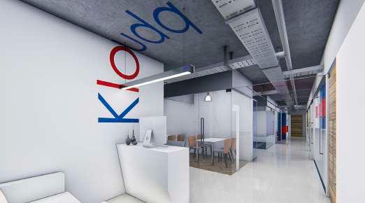
KLOUD- Q
STATUS : ON GOING
SITE AREA : 290 SQM CARPET
TYPOLOGY : OFFICE SPACE INTERIOR
LOCATION : PUNE
Fourth Floor Furniture Layout
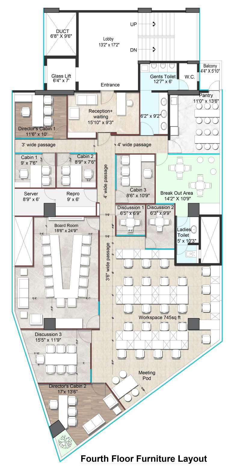
All dimensions are in feet and inches unless otherwise specified. Do not scale the drawing. Only written dimensions are to be followed Dimensions & levels shown to be verified on site before commencing work. Any discrepancies noted be brought to notice of Studio 55 prior to commencement of work. 1. 2. 3. 4. 15 Shivajinagar, Pune 411005 Tel 020 32328703 www.studio55.in File path: Drawing Drawing No: Current revision Issue Date: Floor: Project Code: This drawing is the sole property of Studio 55 architects, Pune. Any use other than mentioned needs prior approval from Studio 55 architects, Pune, India. Project Drawn by: Checked by: SR Scale: Dimensions & levels shown are structural unless other specified. NTS Revision date: 21.02.2022 DK Furniture layout Furniture layout Kloudq Interiors
X:\Studio 55 Interior\Commercial interiors\Kloudq Revamp Client's name Fourth Floor Joints of all paneling work and carpentry material (Ply, MDF, Veneer, Laminates etc.) should be clean with no deviation, gaps, wobbles,etc. In case of any level differences or unfinished work in false ceiling, it is in the scope of the respected vendor to redo it completely as per the architect's requirement. 5. 6. Kloudq Technologies Ltd. Seating Capacity Reception+waiting AREA SEATS 1 2 3 15 14 Cabins (1, 2, 3) 3 29 Extra workstations WALL/ PARTITION LEGENDS Existing Partitions to be Demolished Full Ht. Partitions 6mm thk glass partition (Glass upto 7' Gypsum above,till ceiling) W.C. Gents Toilet Reception+ waiting 15'10" x 9'3" Cabin 3 8'6" x 10'9" Pantry 11'0" x 13'6" 4' wide passage 4' wide passage Entrance Ladies Toilet 5' x 10'3" Workspace 745sq ft
For Discussion
Server 8'9'' x 6' Break Out Area 14'2" X 10'9" Board Room 18'6" x 24'9" Director's Cabin 2 17'x 13'6" Director's Cabin 1 11'6" x 10' 6'2" x 9'2" 12'7" x 6' 3'6" wide passage Cabin 1 9' x 7'6" Discussion 1 6'5" x 6'9" Cabin 2 8'9" x 7'6" Discussion 2 6'3" x 9'9" Discussion 3 15'5" x 11'9" Glass Lift UP DUCT DN 6'8'' X 9'6" 6'4'' x 7' Others Finance Sales HR WORKSTATION LEGENDS 2'-9" Others Finance Sales HR 4'-5" 4' Director Cabins (1,2) Pantry Discussion (1, 2, 3) Board Room TOTAL 3 7 5 12 5 4'-7" 8'-9" 3'-6" 3'-6" 3' 4' 3' 3'-10" 5'-3" 6' 4' 6' 4' 5'-7" 2' 3'-6" Meeting Pod 3' wide passage 6'-5" Repro 9' x 6'

DIVYA KOLI +91-9969964369 , +91-9326791926 EMAIL ID : kolidivya2000@gmail.com