Divya Portfolio
[FORM AND FABRICATION]
[PERFORMATIVE INTELLIGENCE] Hospital Design, Chandigarh, India.
[SIEMENS, DCF, FORCHHEIM] Laboratory Building, Germany
[WEISSENBRUNN GEMEINDEHAUS] Restoration and Extension Project, Germany
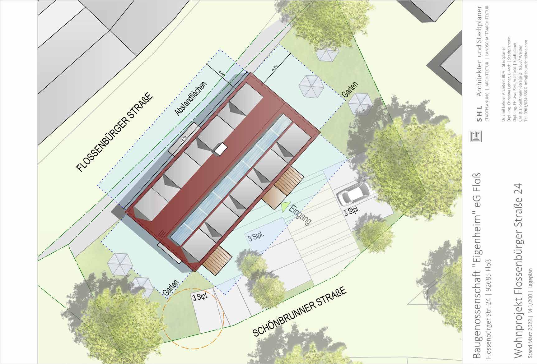
[FLOSSENBURGER
[CONSTRUE] Private Residence, Panchkula, India [CONTENTS]
[OBERVIECHTACH UNTERKUNFTGEBAUDE] MachberkeitStudy, Bavaria, Germany
01
Crowd sourcing public game 02 [VISUAL STUDIES] Deep Texture and Strong Silhouette 03
[CO-CONSTRUCT]
04
[HYPERTHREADS] Worrkshop, Bangalore, India
05
06
07
08
09
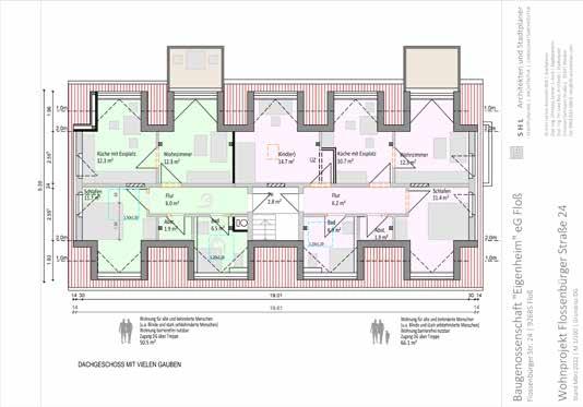
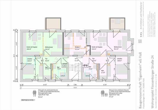
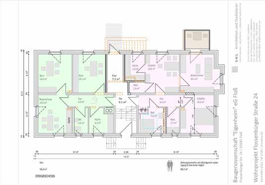
STRASSE] Renovation Project, Germany
10
[CO-CONSTRUCT]
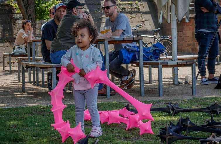
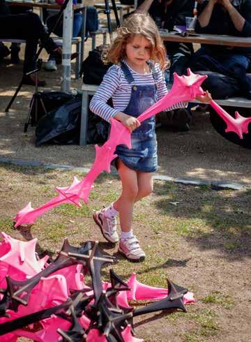
Distributed Public Game, Master Thesis Project in Advanced Architectural Design at SAC.
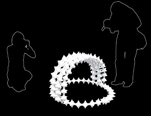
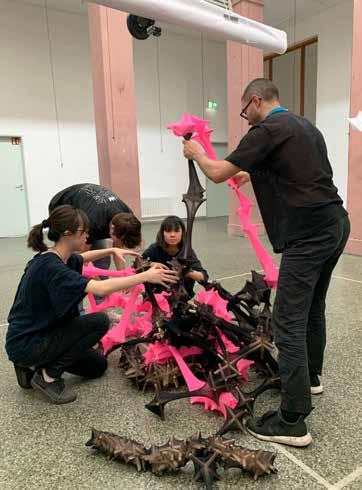
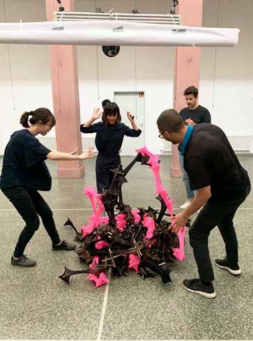
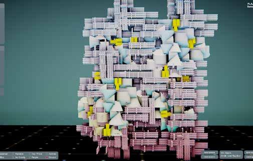
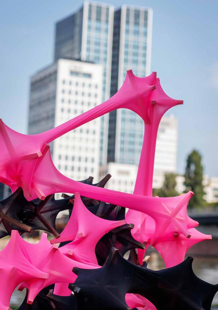
Co-Construct is a public urban game designed to speculate on participatory approach towards design and space making.
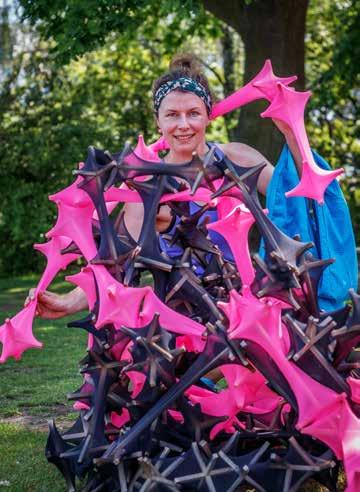
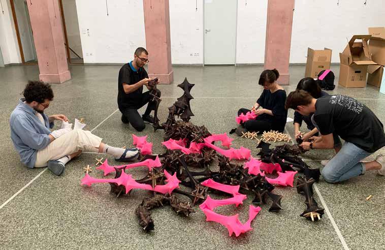
Co-Construct explores the visual language of a conscious body. Cognizant is conceptualized as an urban toy, a distributed social game and collective ‘making’ experience that seeks to engage people in order to construct open-ended design formations. The participatory design process aims to bring phenomena of social networks and game culture to the physical environment at urban scale. The collective act of coming to one place building together becomes a shared memory for people attending. The energy for Cognizant is sourced from people’s interactions. None of the pieces can do anything on its own, and only when they are put together do the game “Co-Construct” emerges.
link to the video:
https://vimeo.com/349143037
https://vimeo.com/354972408
https://vimeo.com/354971209
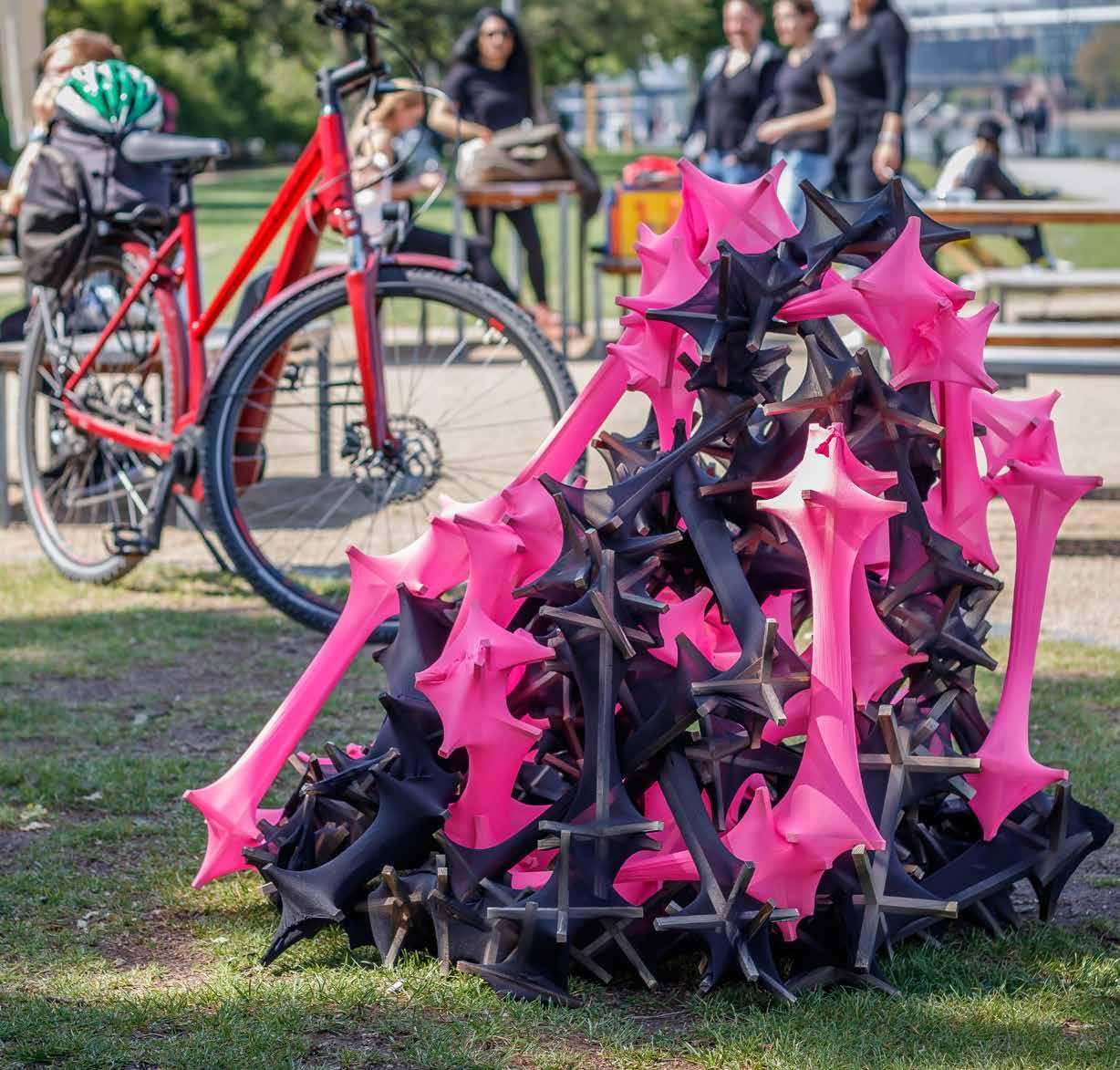
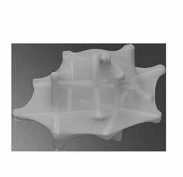

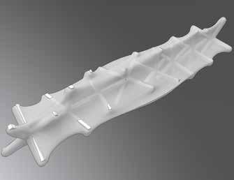
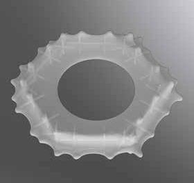
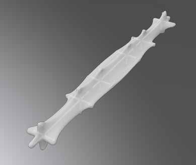
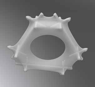
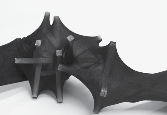
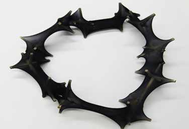
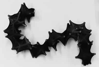
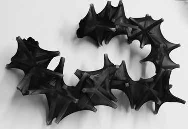
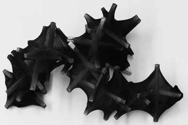
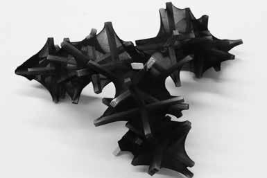
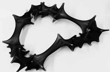
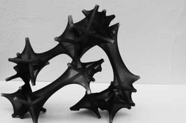
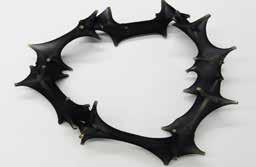
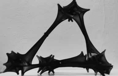
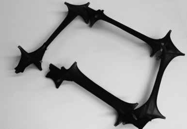
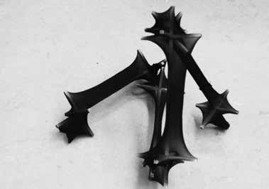
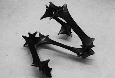
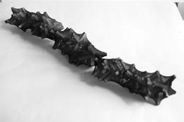
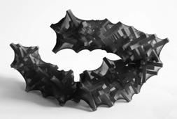
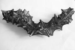
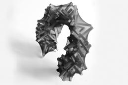
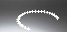
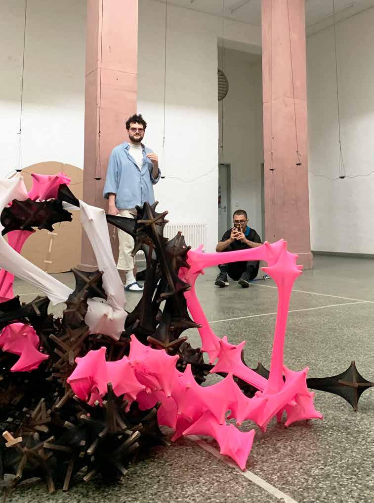
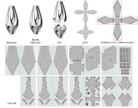
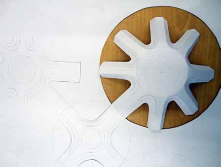
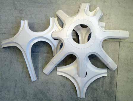
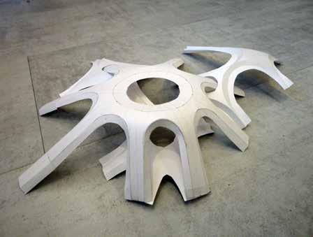
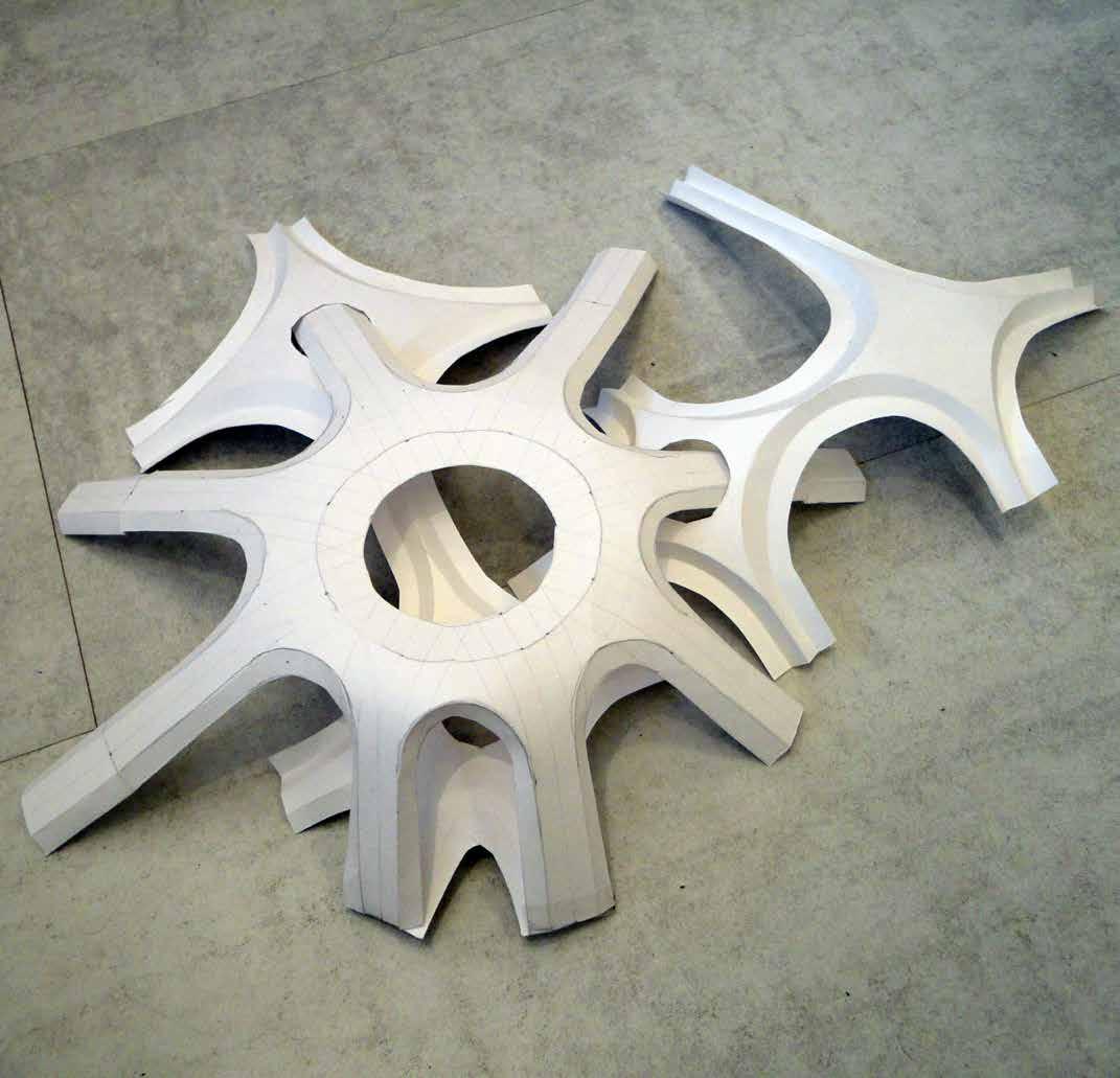
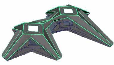
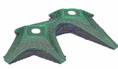
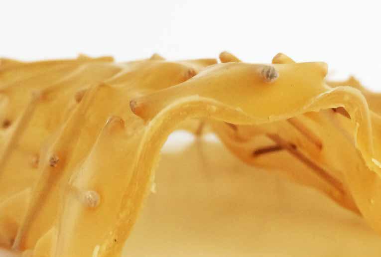
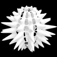
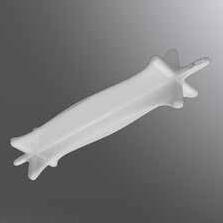
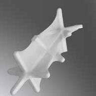
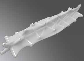
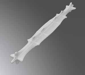
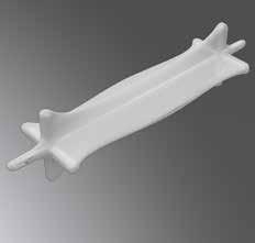
Physical prototypes designed based on skeleton aggregation logic with respect to the skin. Stitching and different aggregation techniques result in different folding behavior onto each prototype. An extensive application logic has been derived on the aggregation of spicules and resulting outcome behavior to analyze the differences between the outcomes.
textile engineer
the
as a way of Conceptualization
Based
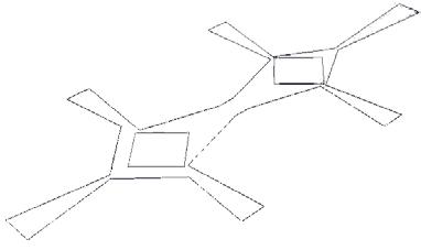
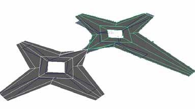
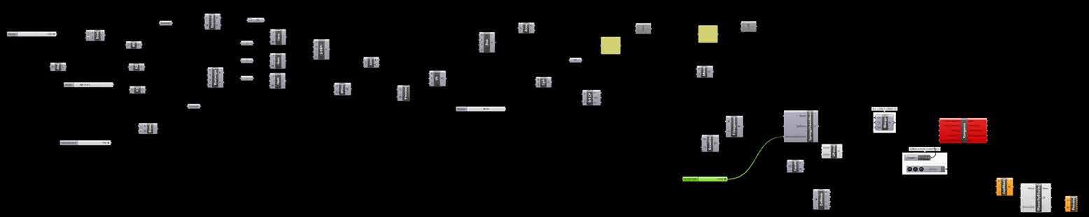
Digital
simulations of the prototypes with different spicule arrangement and typology analyzing the
with respect to
loosely arranged wooden aggregates. Prototyping
Agent
Design

skeleton
homogeneous
05] skeleon
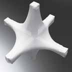
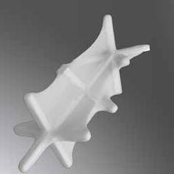
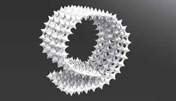
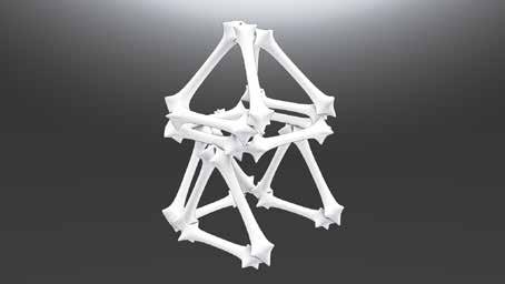
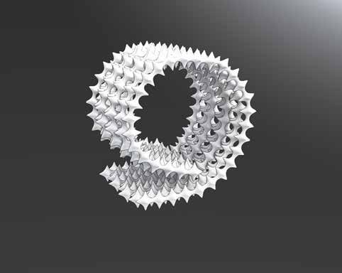
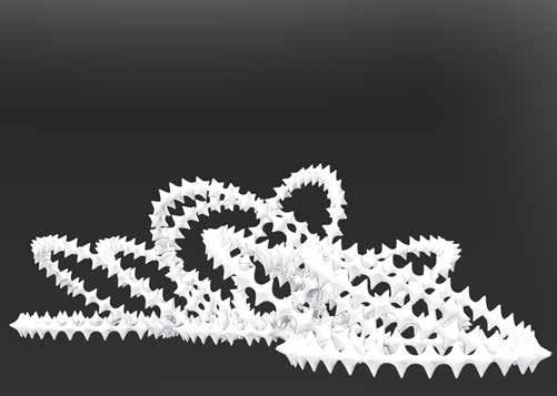
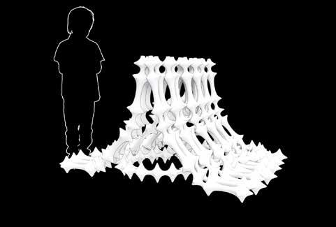
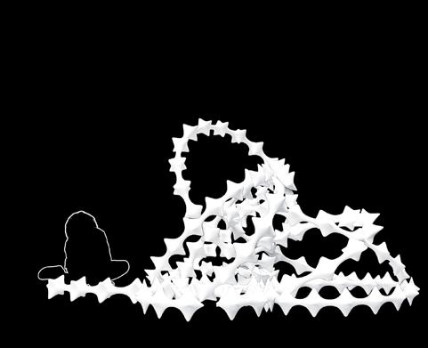
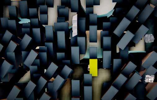
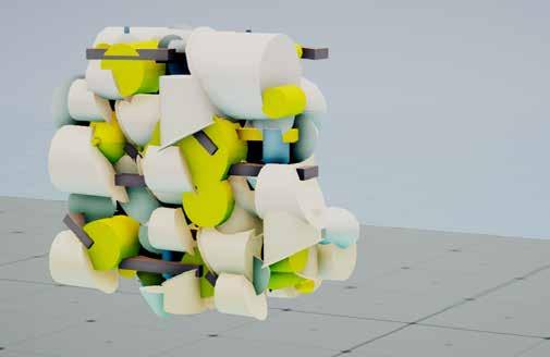
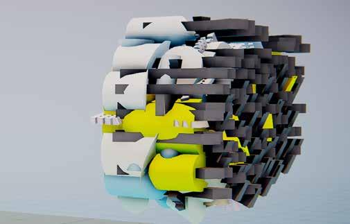
6 homogeneous spicule arrangement [type 06] skeleton type 6 homogeneous spicule arrangement [type 04] skeleton type 4 & 6 homogeneous spicule arrangement [type 02] skeleton type 2 with stitch Module Typology and Behavior homogeneous spicule arrangement [type 07] skeleton type 1 with stitch hybrid spicule arrangement [type 8] skeleton type 1 & 2 Diagrams illustrate the outcome of the various types of modules based on variation in the aggregation and tensioning constraints i.e. the length of textile strands and skeleton type. Each of the module behaviour results in various outcomes from flexible to rigid. Differences in each of the module type depend on the symbiotic relationship generated between constraints when they are put together. Some of the Patterns derived are similar in their outcome but with varying degree of folding. Pattern Derivation
[Open Ended] [Close Ended]
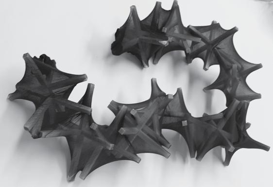
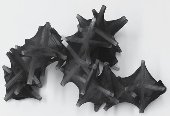
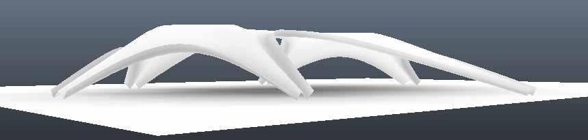
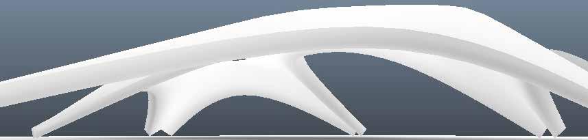
[Linear] [Stitched Body] [Rigid Body] [Arches] Images show various module typology resulting from constraint aggregation arrangement over the textile membrane in variety of ways. Folding of the modules controlled by the spicule logic results in flexible to rigid linear strands, to rigid geometrical entities to highly rigid assembling modules. Inherent consciousness of the skin accomplished through tensioning and interlocking comes into play to create different assembling behaviour. A consistent dialogue between two species results in a conscious system.
homogeneous spicule arrangement [type 01]
type 2 homogeneous spicule arrangement [type 03] skeleton type 2 & 4
spicule arrangement [type
type
[Bifurcation]
[Curvilinear]


Rule Set for Game Development as Co-Construct Various
Variety
Put them together in your
way
derive new patterns
ways of exploring Co-Construct The above rule set explains the way the game has been developed to achieve the notion of participatory design. A three step ruleset derived to communicate and help engage the participants along with giving them opportunity to engage, evolve new sequences or use the defined ones to play and achieve open ended design formations. Thus, crowd sourcing is accomplished through this defined ruleset as a way for people to approach “cognizant”.
Co-construct seeks to engage people at collective level where collective comes into action when people interact with “cognizant” and evolve and co-evolve new ways of designing space and themselves. A way of approaching architecture through Architecture Intelligence and communication with our environment and each other enabling us to think how we can interact and involve with our surroundings in future. Diagrams above show co-construct with human agent where open ended design formations are achieved by applying the ruleset. The participatory design approach brings phenomena of crowd sourcing as a way of space making through introduction of game culture in the discourse.
sequence evolved from varying arrangement of set of spicules.
of spicules explored as constraints to derive a logic set for the participants and create their own prototype.
own
and
and
Co-Construct and Human Agent

designing
Real-time
of
as a game being organized at Frankfurt Maincafe with a given instruction set for the participants to involve. The game involved people from various age groups playing in their
ways.
“Co-Construct” being organized at Staedelschule Licht Halle with an aim to organize a workshop and help participants engage in
a more democratic way by
cognizant in their own ways and thus, following the ruleset to create design formations.
documentation
“Co-Construct”
own
[VISUAL STUDIES]
Deep Texture and Strong Silhouette, first semester work at SAC.
The work problematizes about contemporary image culture through critical study and analysis of images. This involves Visual studies including rationalizing formal properties of objects and images which further help in evolution of one’s interest in a specific field of study. With the aim to study about different experimental workflows and generating a relation between these workflows, the project has been evolved not as a solution but an intensive study towards a new image culture.
With the intent to understand object oriented ontology the result has been achieved by amalgamation of two different workflows i.e. visually analyze chosen painting by Marx Ernst and produce literal or implied space of the painting to 3 dimensional speculative graphic space and visual study of image data generated using special composition techniques respectively which direct towards making a case termed “Deep texture and strong silhouette.”
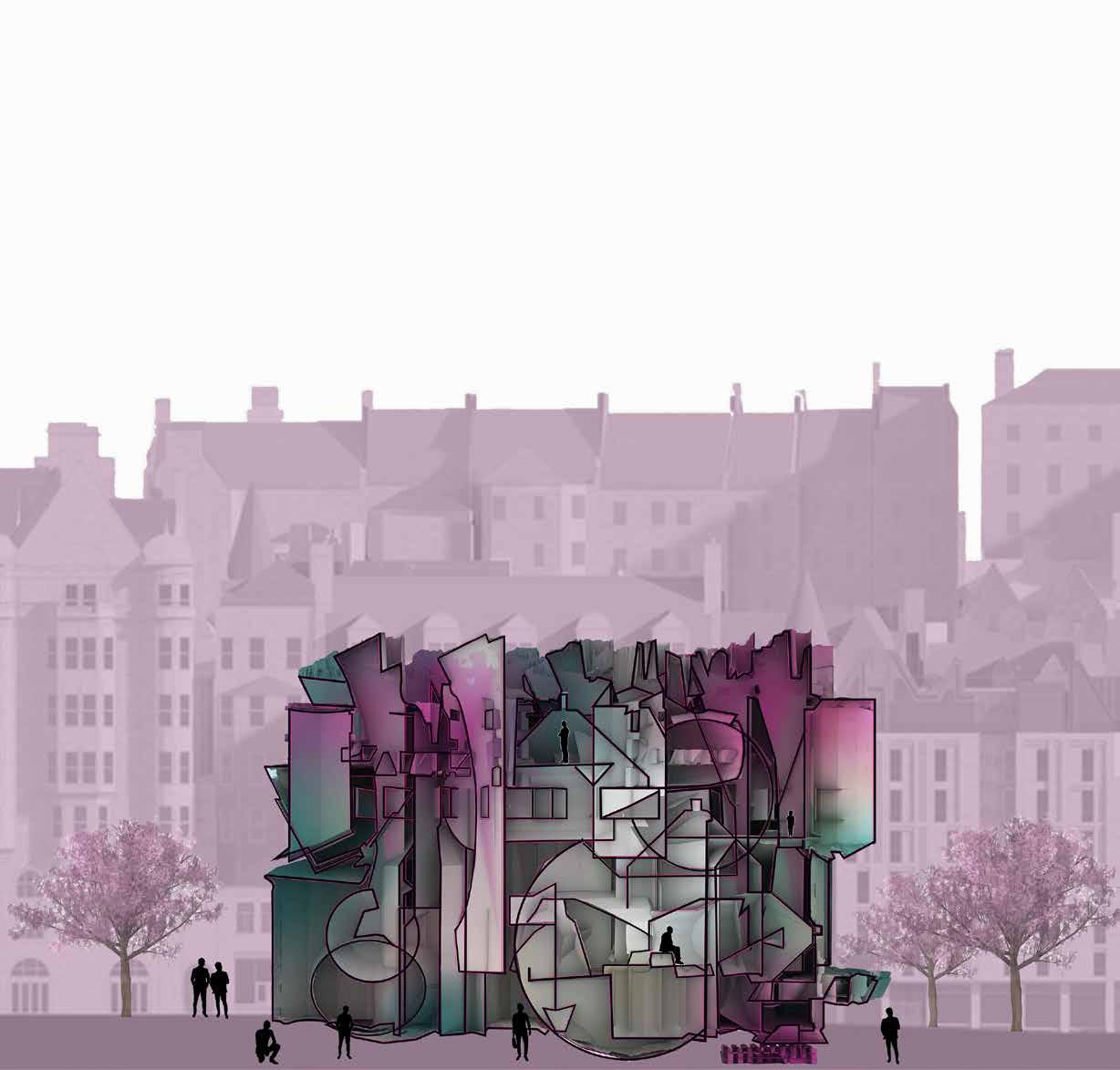
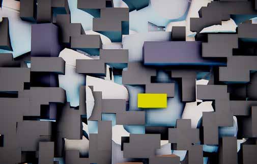
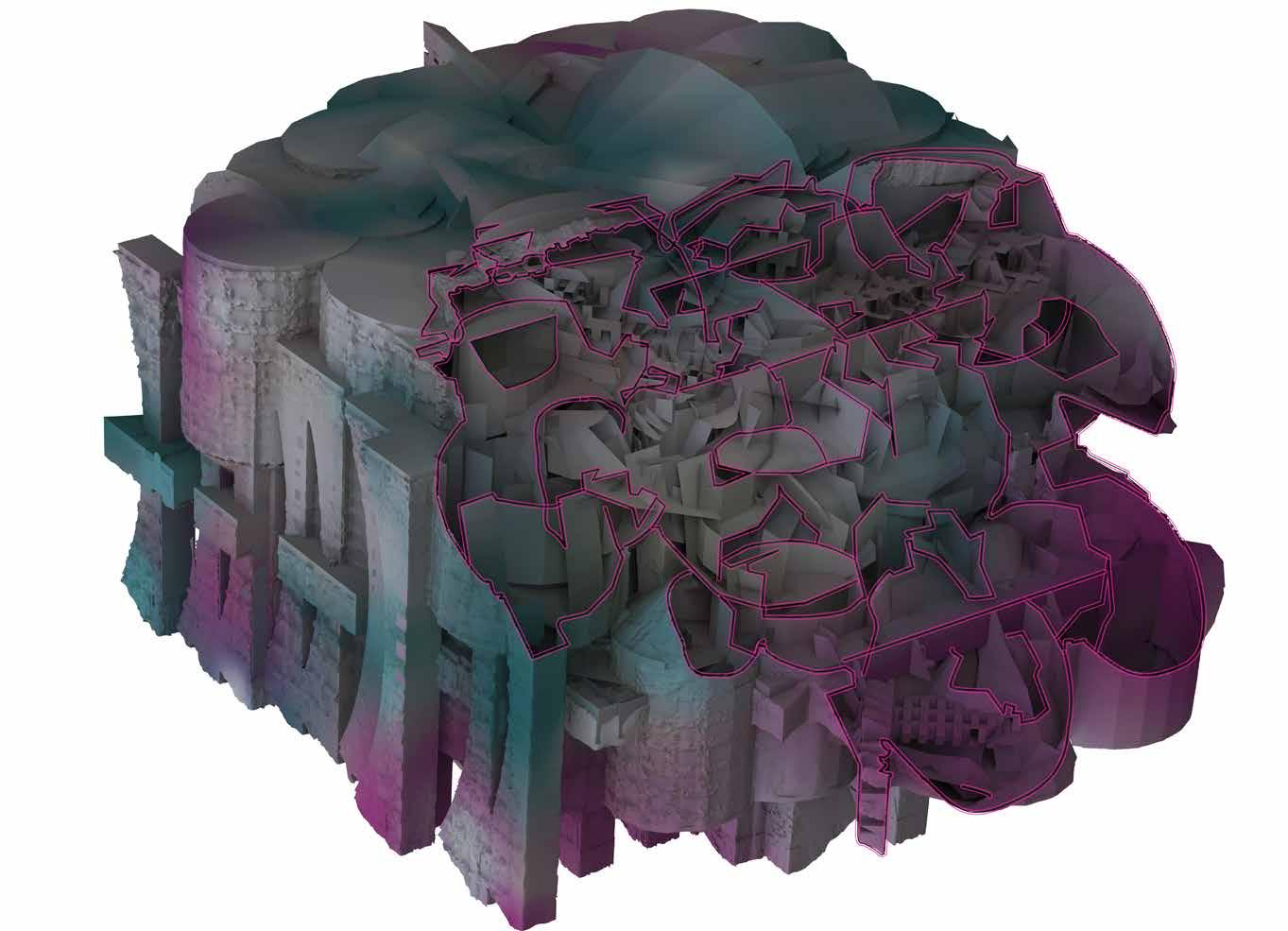
The catalogue above show set of selected images which have 2 specific characteristics i.e. texture and silhouette resulting by amalgamation, repetition and arrangement of defined set of objects. These characteristics are further developed using a strategy towards designing a “heterogeneous object”. The object is thus explained through the argument made as “Deep texture and Strong silhouette”.
of images with an aim to design and define “texture” as a formal quality using various 2 dimensional and 3 dimensional ways of arrangement of the pre-defined set of objects.
Set
of
an aim to design and define objects with a highly defined “silhouette” as a formal quality using various 2 dimensional and 3 dimensional ways of arrangement of the pre-defined set of objects. Formal Qualities
Set
images with
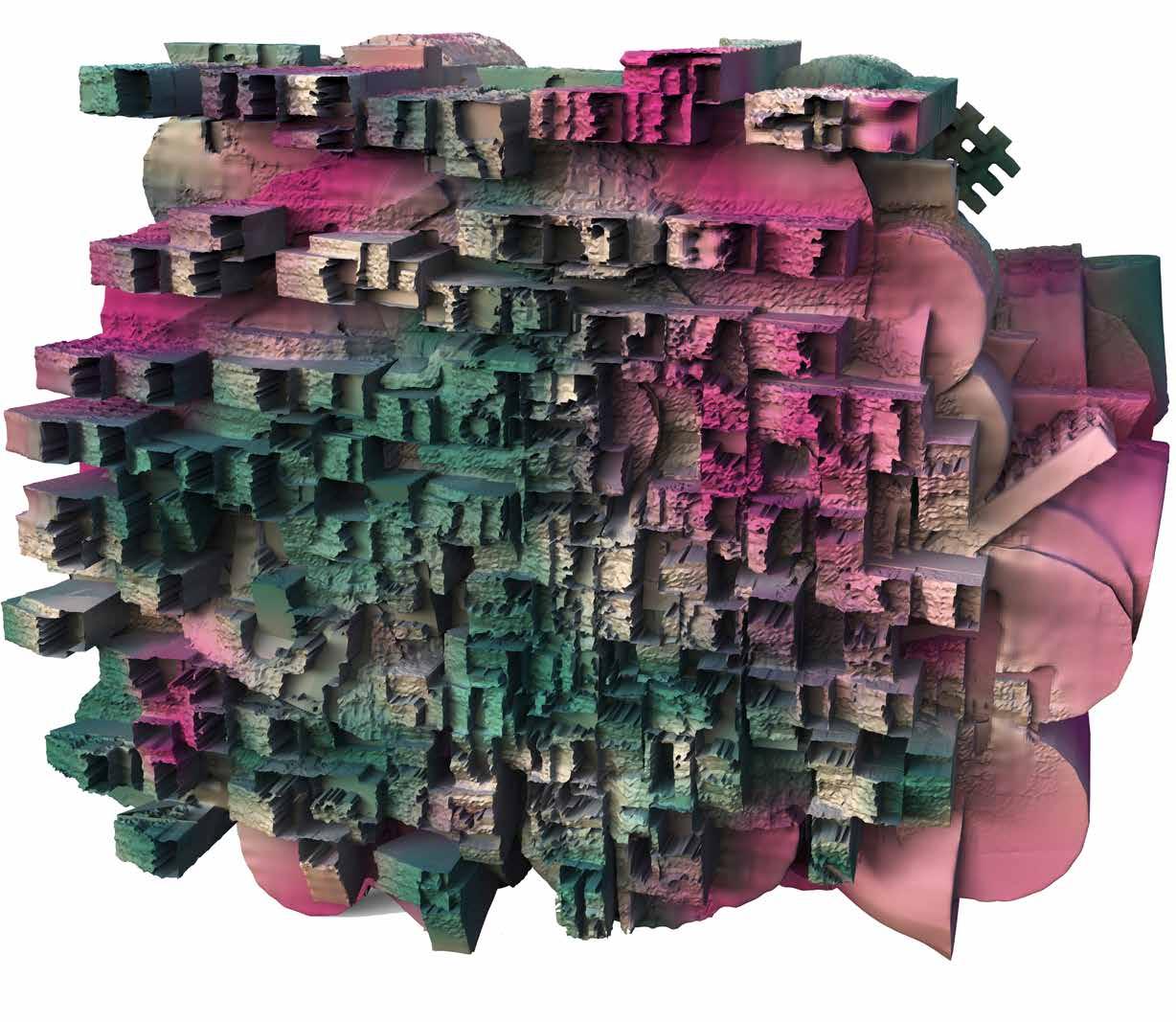
Axonometric View showing detailed overview of the interior core of dense set of intersecting set of pre-defined objects along with a heterogeneous facade on all sides. The object is a new way of achieving and perceiving a 3-dimensional object in digital space. The outcome object is a way to speculate towards designing a new contemporary and futuristic space through the use of readymade objects in a world already full of pre-existing information i.e. readymade architectural objects.
Heterogeneous Object
Axonometric View
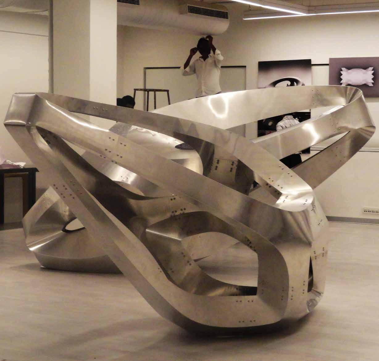
[HYPERTHREADS]
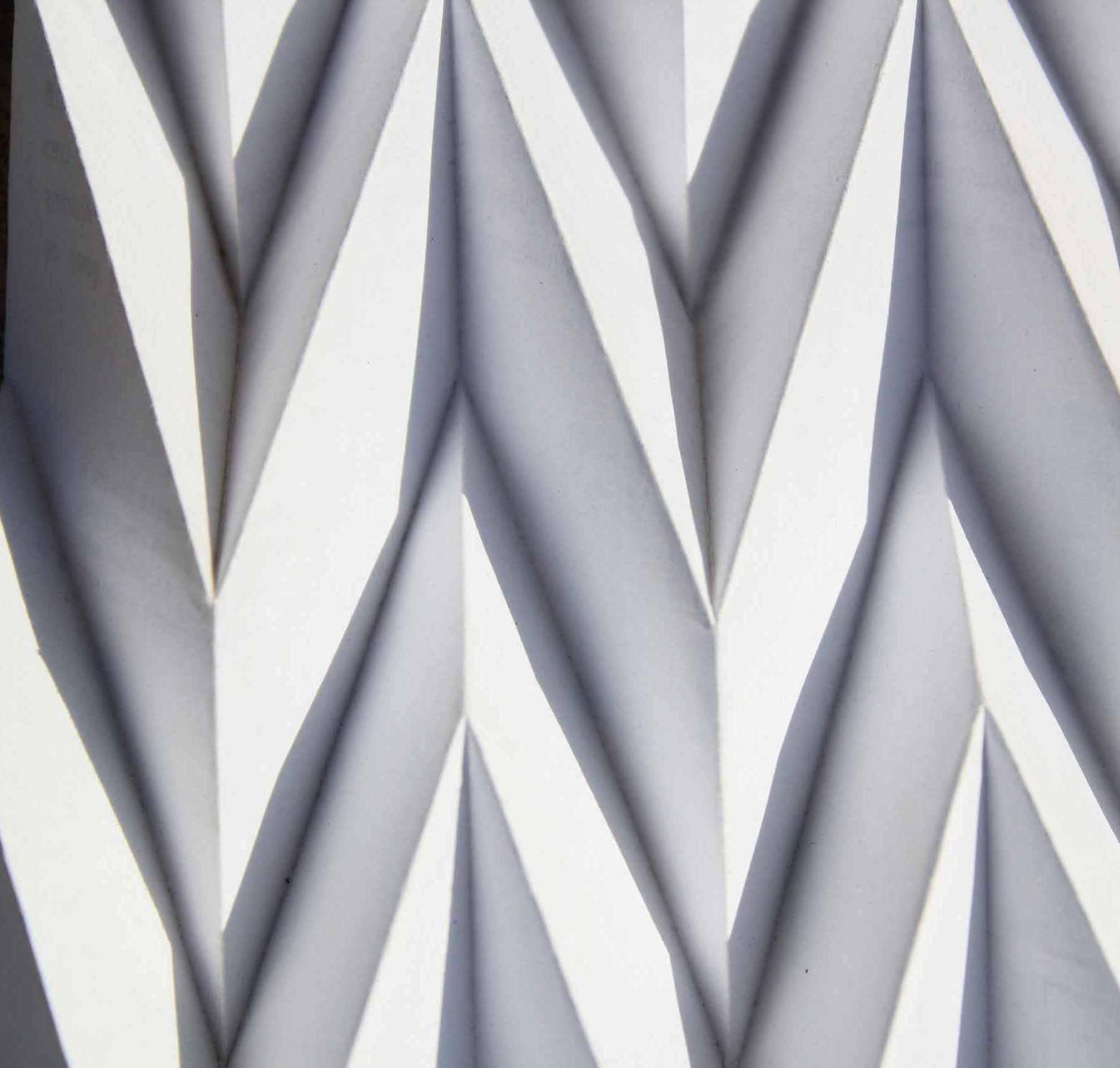
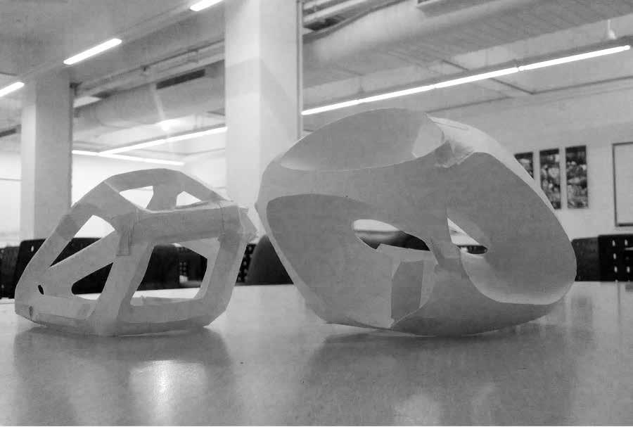
The aim of the workshop is Intuitive designing from sheet to form which is subjected to geometry and material. Objectives include understanding the impact of various types of folds and curves on paper acting as a structure in itself. Thus analysing the structural stability. Further exploration of physical prototypes into digital explorations further testing their strength.
 Geometrical Analysis
and fabrication techniques include computer aided manufacturing to install the predesigned module.
Geometrical analysis
Form Finding and Digital Development Paper Modelling
Geometrical analysis and fabrication techniques include computer aided manufacturing to install the predesigned module.
[FORM AND FABRICATION]
This includes set of selected work showcasing different ways of experimenting and fabrication using variety of materials from metal to paper, latex, silicon, wood and textile.
Fabrication
Digital Explorations
Simulation Techniques
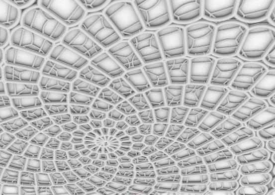
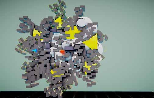
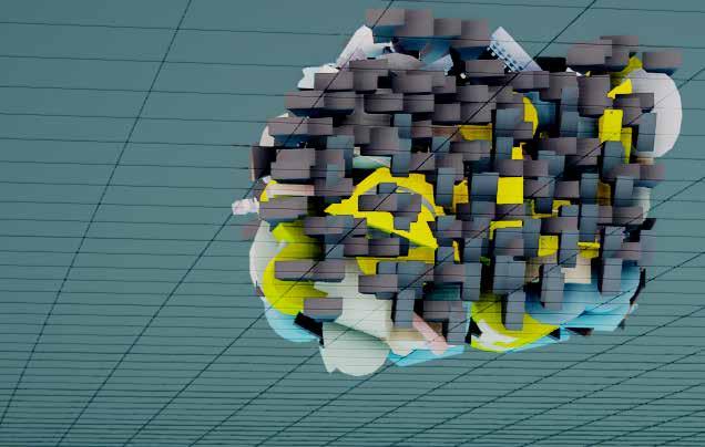
Radial taxonomy
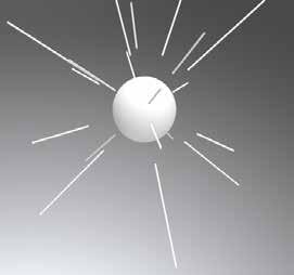


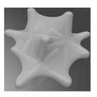
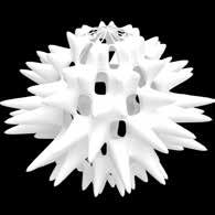
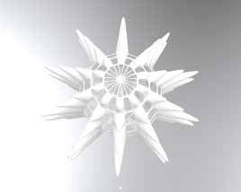
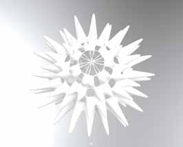

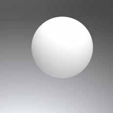
Digital explorations showing radial taxonomy being applied onto spherical geometry to obtain different results. The outward force leading to deformations in the geomtery thus resulting in different outcomes.
script generated to apply Radial Taxonomy on spherical object.
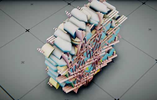
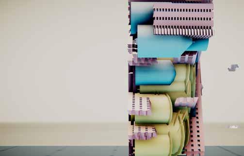
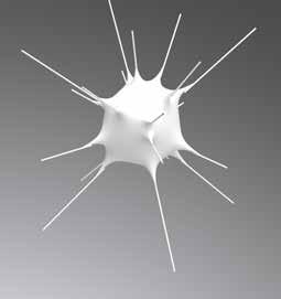
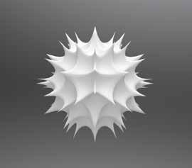
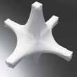
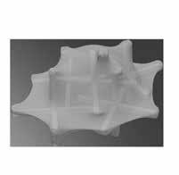
Clustered aggregation and strand aggregation

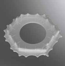
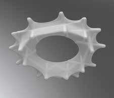
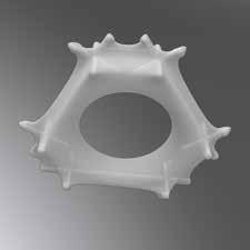
Simulation Techniques showing Aggregation using varying number of skeletons over textile membrane with an icosahedron geometry to analyse skin behaviour wrt each arrangement.
Grasshopper and Maya based simulation applied using varying skeletons over textile membrane to analyse skin behaviour wrt each arrangement.
Link to animations: https://vimeo.com/354972408
Digital Explorations
Grasshopper
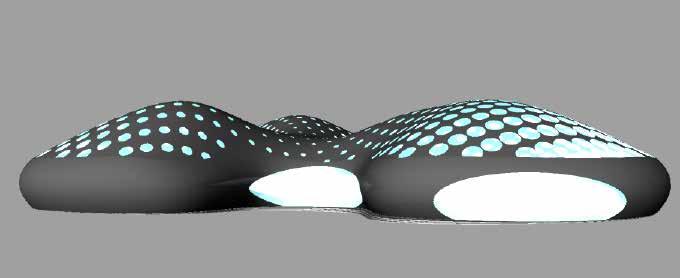
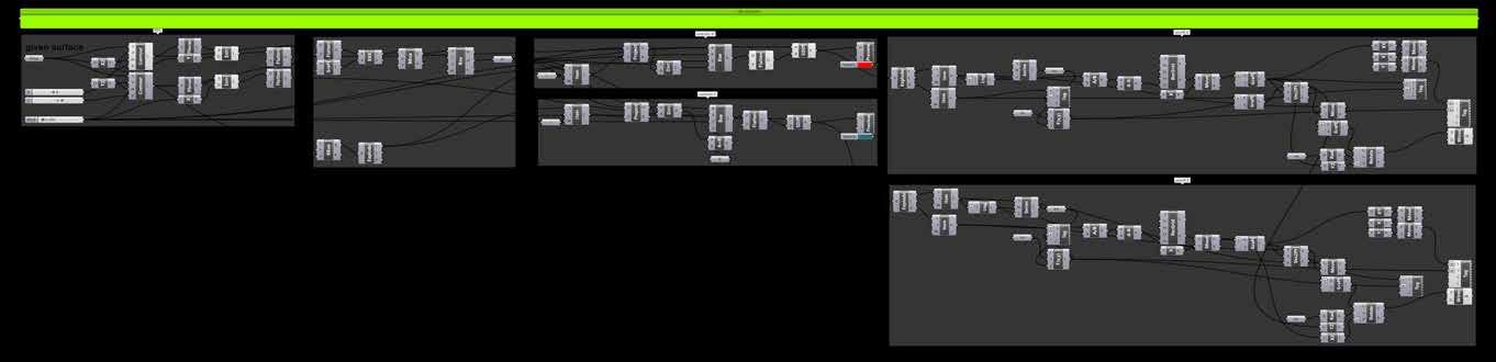
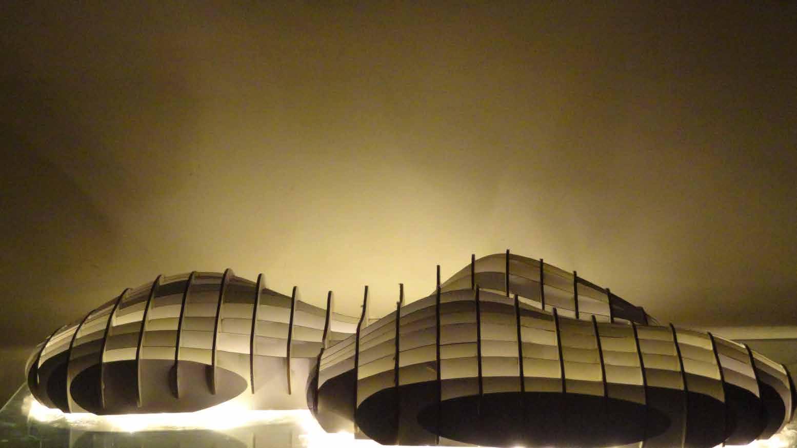
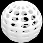
Digital and Physical Prototype for a Pavilion. Perforated Roof Design developed using parametric techniques. Rib structure technique using grasshopper was used to create the physical prototype. Pavilion Design Digital Exploration Physical Prototype
School Design
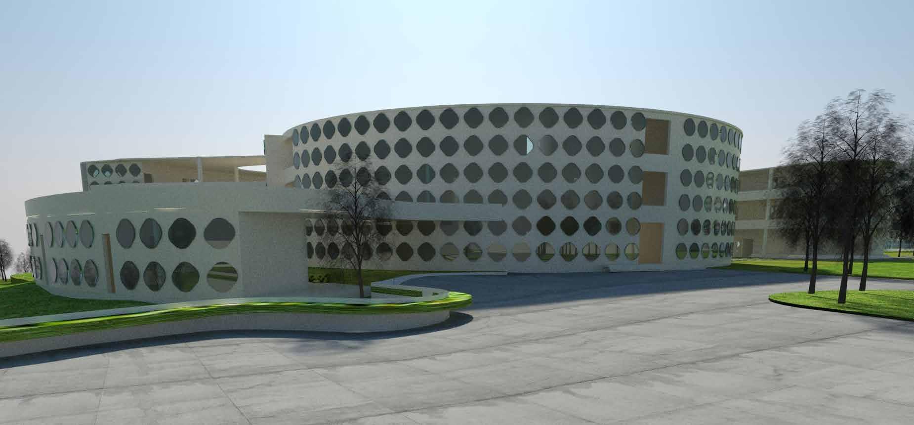
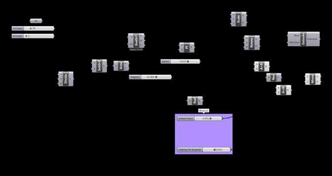
3 D Model developed for School Design. The intent was to provide a new visual language to the building. Along with the design process and spatial devellopment a new facade was developed throughout the complex to give a contemporary outlook to the school building. the outer facade was a shell of perforated windows provided to cater to the functional requirements of the porject and along with that providing a new visual language to it.
To the right: Grasshopper script developed to work out the outer facade shell for the building.
Design Development
Spatial Organization
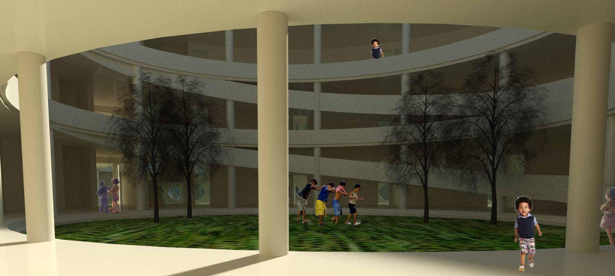
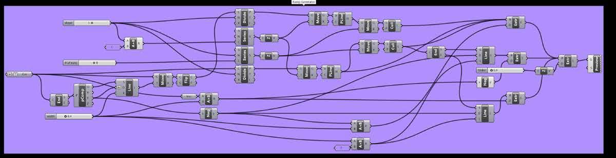
Spatial Organization including courtyard space and circulation elements revolving around it. The courtyard space is a means of recreation, gathering, play and provding solution to the climatic conditions of the region. The ramp has been design as a playful elemen being a circulation element.
To The Right: Grasshopper script showing evolution of the ramp and its surroundings.
Digital Explorations Facade Development for
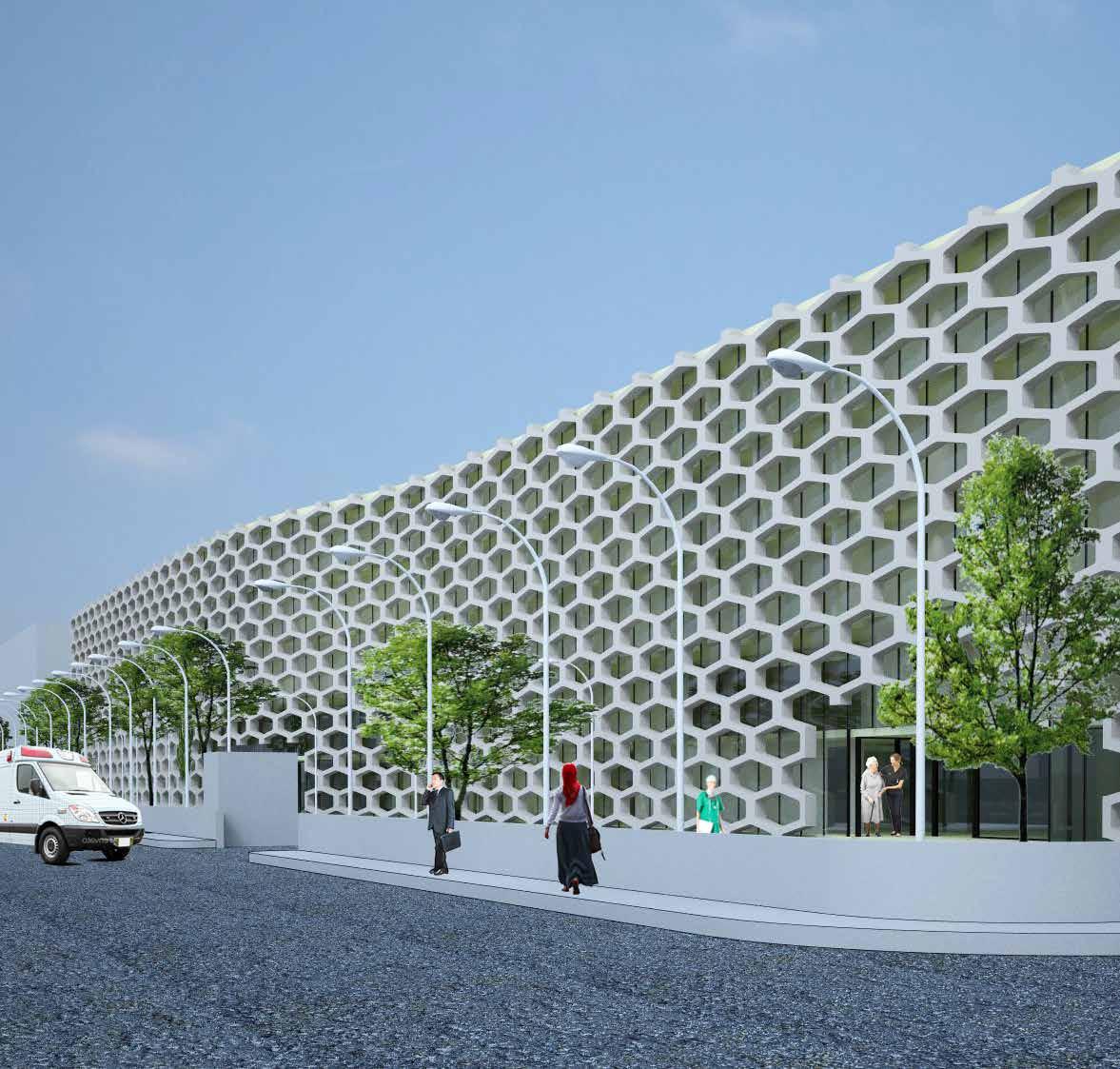
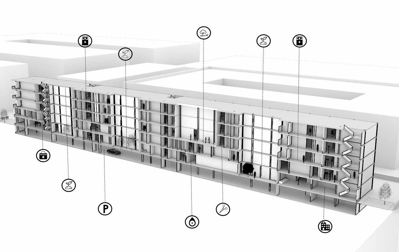
[PERFORMATIVE INTELLIGENCE]
Hospital Design, Chandigarh, India.
The project is an extension to the existing hospital complex of PGIMER, Chandigarh. The project aims to design and execute a 200 bedded multi speciality hospital in the block. A highly specialized and well designed space based on the climatic conditions of the region is the aim of the project.
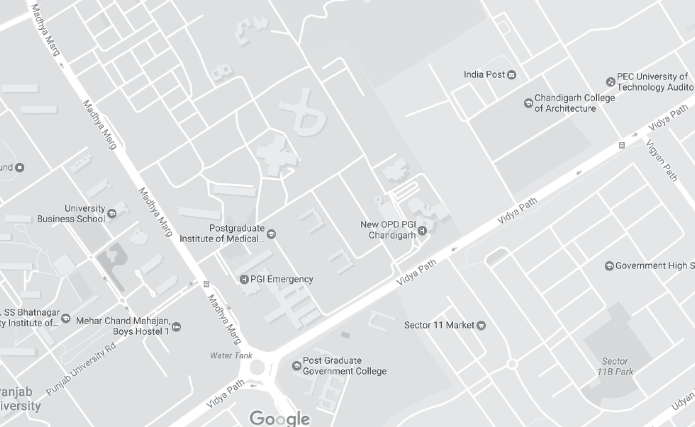
Map of the existing campus of PGIMER, Chandigarh and its connection to the other sectors along madhya marg. The new site is an extension to the existing nehru hospital adjacent to the site. Site
Surroundings Existing Block PGIMER City Road Network V3 Sectoral Road Network V2 Main Entrance 01 Entrance 02 Site for New Multi Speciality Block
and
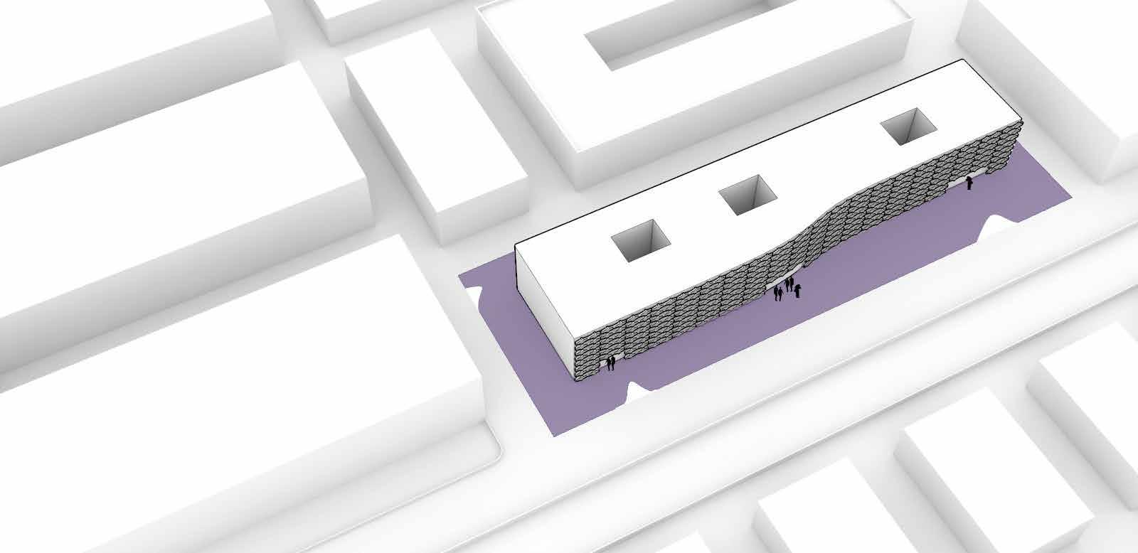


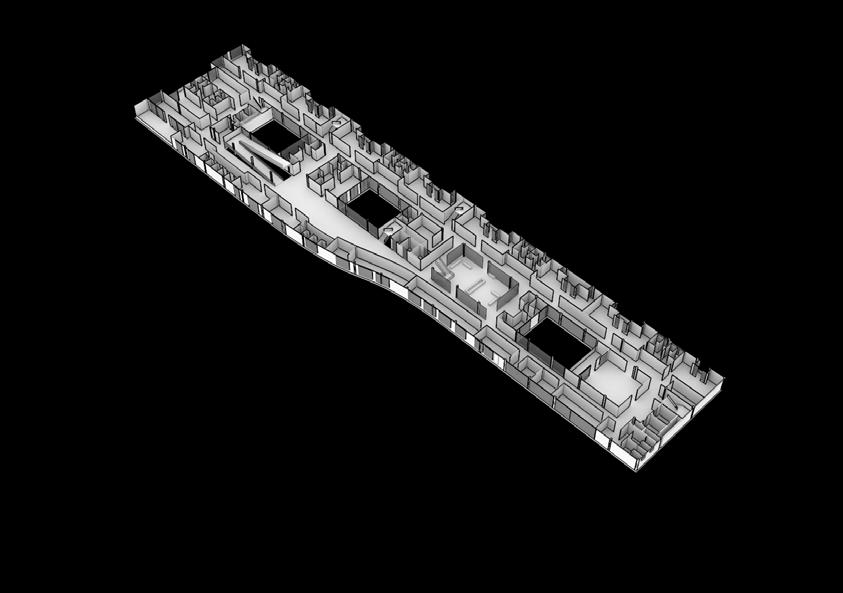

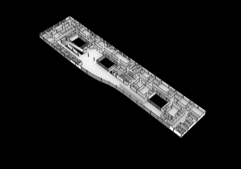
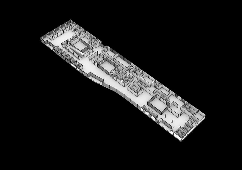
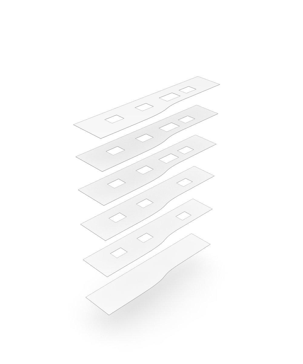
Services Outpatient Department Outpatient Department (Maternity/Obstetrics) Inpatient Department Inpatient Department Inpatient Department Emergency and Diagnostics O.T. Complex Service Entry Lower Ground Floor Plan Ground Floor Plan First Floor Plan Second Floor Plan Third Floor Plan Fourth Floor Plan Exit Central Service Core Recreational Zone Design Development Schematic diagram showing allocation of OPD and IPD departments and their services in the hospital. Plot size is 8498.5 sq. metreand is located adjacent to the existing nehru hospital in the campus of PGIMER, chandigarh. ? SITE The plot is connected to the other areas through major axial roads within the campus. There are separate service entry and main entrance and exit is through the parallel road running along the plot. ACCESS Longitudnal blocking has been done according to the plot shape and direction. BLOCKING Provision of courtyards for cross ventilation and natural lighting within the hospital block. COURTYARD ALLOCATION Diagrams showing conceptual stages from site layout including access and orientation to courtyard planning within the building block catering to the climatic conditions of the region. These courtyard spaces include spaces for recovery and recreation of the users. Design Conceptualization Main Entrance Exit Service Entry
Facade
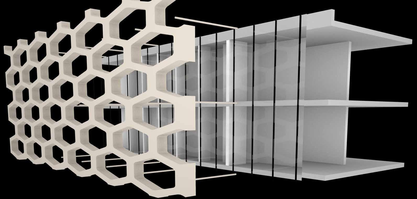
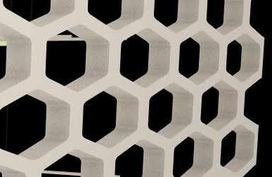
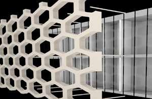
Details of facade based on hexagonal grid pattern. Each hexagonal unit is considered hollow with perforations to act as skin for the internal layer of the exterior of the block providing both ventilation and shelter from direct south sun on the facade.
Development
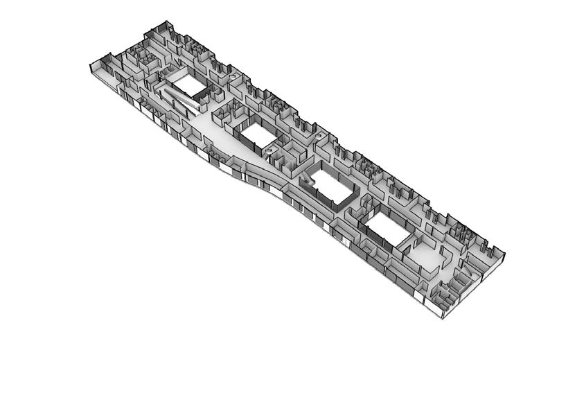
the building showing vertical arrangement
the block
Isometric section through
across
COURTYARD 01 PARKING BLOOD BANK O.T. COMPLEX EMERGENCY IPD 01 IPD 02 RECREATIONAL ZONE COURTYARD 03 COURTYARD 02 Design is based on the performance of all the functional regions therefore location of each region has been of main consideration in the design process. Provision of three courtyards within the longitundinal block provide with natural light and ventilation across the block.
OPD
[LABORATORY BUIDLING]
Siemens Healthineers DCF, Forchheim
The work problematizes design development and execution of the laboratory space and technical space required for the project. The main goal is Digitizing projects using Building Information Modeling techniques to achieve highly efficient user oriented solutions.
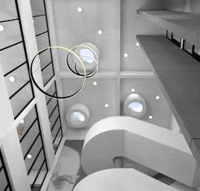
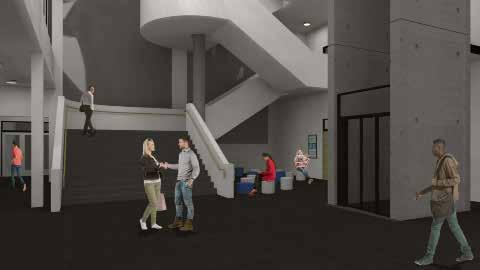
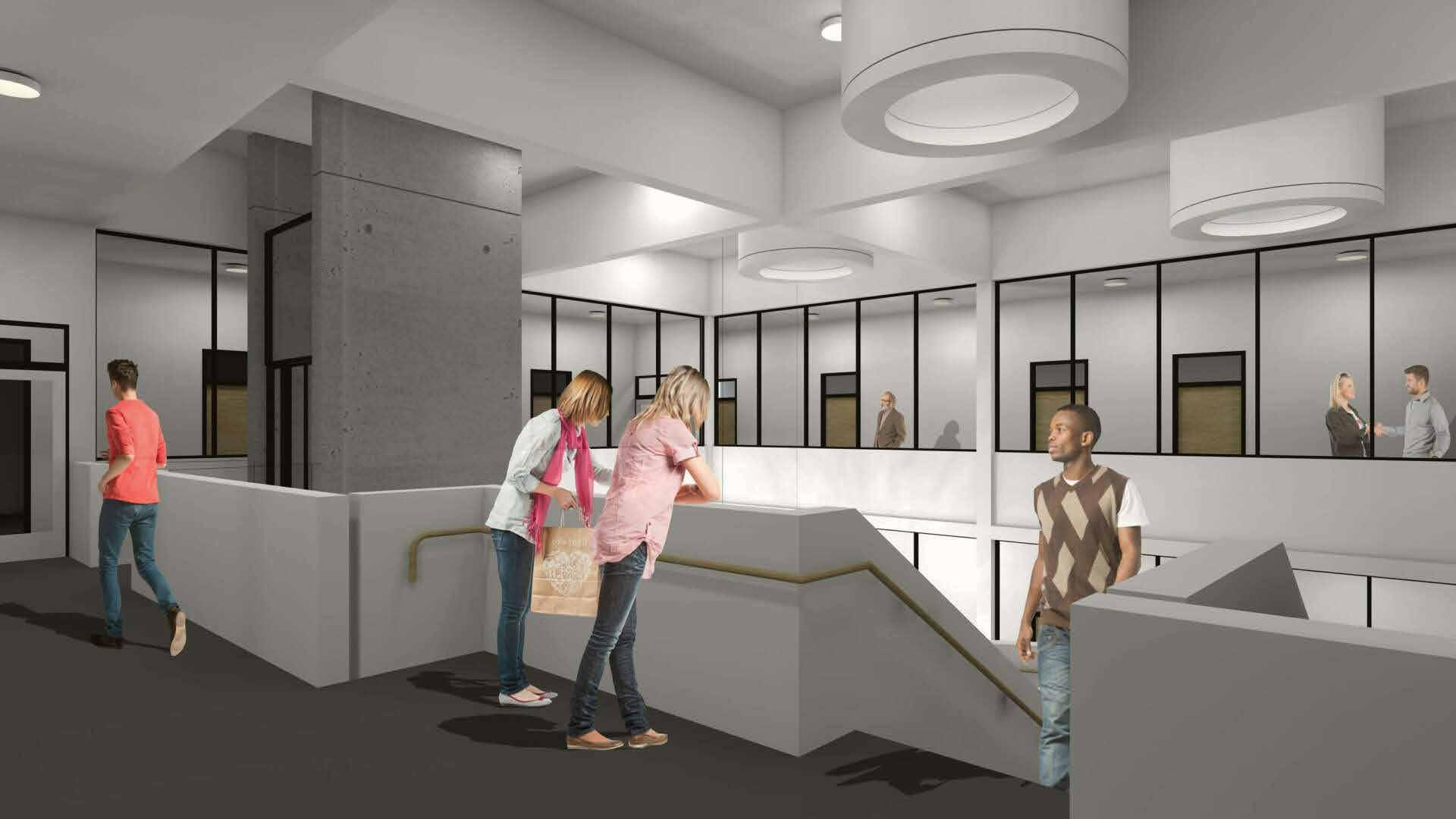
Laboratory Building Foyer Overview
Renders show the 3 major parts of the building complex. The Technical Space, Laboratory Space and Foyer/Meeting Space. The new building complex follows the visual language of contemporary aesthetic techniques along with reviving the exisitng and providing a relatable outcome to the whole complex.
Residential Building 3D View
Renders show a small residential Set up in the surroundings of Frankfurt. The idea was to provide a concept design for the residence.
FB_02: 1
FB_03
_GD_100_Bd FB_03
FB_03: 3
FB_04
_GD_100_Al FB_04
FB_04: 2
GD_01
_GD_200_BK GD_01
GD_01:
GD_03
_GD_250_WH GD_03
GD_03: Gesamt: 15
Floor Plan
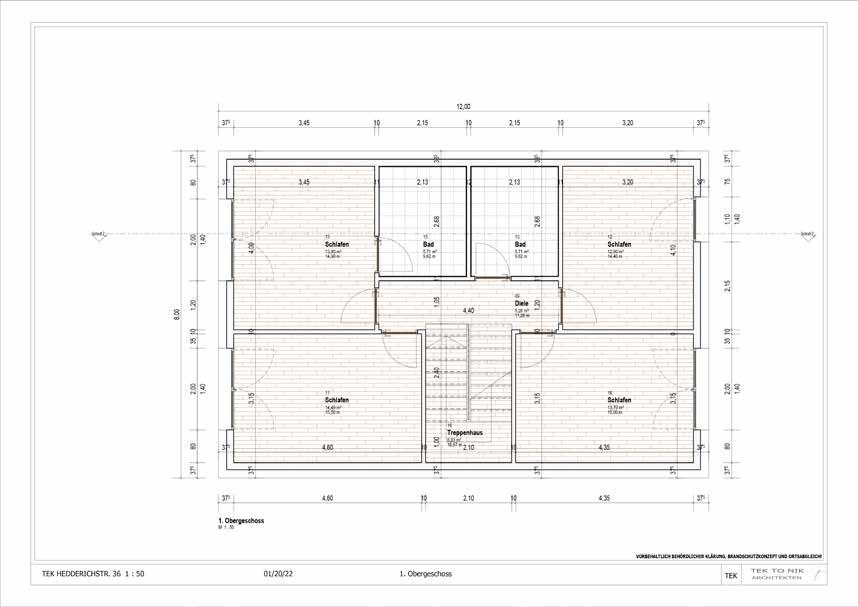
00_EBENENLISTE Typ Name Ansicht Gebäudegeschoss Geschoss darüber Tragwerk Ebene OK FFB 09_UG_OK_FFB -1,00 m Ja Standard Nein Ebene OK FFB 10_EG_OK_FFB 0,00 m Ja Standard Nein Ebene OK FFB 11_1OG_OK_FFB 3,00 m Ja Standard Nein Ebene OK FFB 12_2OG_OK_FFB 6,00 m Nein Standard Nein Ebene Rohbau Oberkante 10_EG_OK_RD -0,10 m Nein Standard Ja Ebene Rohbau Oberkante 11_1OG_OK_RD 2,90 m Nein Standard Ja Ebene Rohbau Oberkante 12_2OG_OK_RD 5,90 m Nein Standard Ja Ebene Rohbau Unterkante 10_EG_UK_RD -0,35 m Nein Standard Nein Ebene Rohbau Unterkante 11_1OG_UK_RD 2,65 m Nein Standard Nein Ebene Rohbau Unterkante 12_2OG_UK_RD 5,65 m Nein Standard Nein Typ Geschoss Beschreibung DL_800x2000 1-teilig ML_1000x2136 1-teilig ML_1260x2135_GF_800 2-teilig Gesamt: 11 Typ Typenmarkierung _WF_375 WF_01 _WI_10 _WI_10_F WI_02 _WI_100 WI_01 Gesamt: 37 RÄUME-nach Ebene mit Fläche & Umfang Nummer Name Umfang Brutto 10_EG_OK_FFB 01 Flur 11,89 m 6,68 m² 02 Küche 13,50 m 10,44 m² 03 Wohnen/Éssen 23,70 m 33,35 m² 04 Büro 15,00 m 13,70 m² 05 Bad 9,00 m 5,04 m² 06 Diele 7,20 m 3,15 m² 07 Treppenhaus 10,69 m 6,83 m² 08 Balkon 15,10 m 9,08 m² 11_1OG_OK_FFB 13,70 m² 14,49 m² 12,80 m² 13,80 m² 5,71 m² 5,71 m² 12,11 m² 81,56 m² ING GESCHOSSDECKENLISTE Typ Typenmarkierun g Anzahl Umfang Fläche Volumen Beschreibung _GD_100_Diele 1 16,10 m 9,83 m² 0,98 m³FB_100_Diele 16,10 m 9,83 m² 0,98 m³ FB_01 _GD_100_Wo FB_01 3 146,18 m 189,33 m² 18,93 m³FB_100_Wohnung
3 146,18 m 189,33 m² 18,93 m³ FB_02 _GD_100_Ku FB_02 1 13,50 m 10,44 m² 1,04 m³FB_100_Küche
FB_01:
A U F
A B B 4 4 3 3 2 2 1 1 Küche Bad 23,70 m Wohnen/Éssen Büro Flur 1 4 0 2 1 3 1 4 0 3 0 3 0 3 0 3 0 3 0 3 0 1 7 5 1,50 37 4,35 10 2,10 10 4,60 37 12,00 3 7 8 0 2 2 5 2 0 0 1 6 5 2 2 5 2 0 0 8 0 3 7 8 0 0 37 4,60 10 2,20 4,35 37 9 7 6 0 5 9 7 37 4,60 10 2,10 10 4,35 37 3 7 3 1 5 1 0 1 5 0 1 0 2 4 0 3 7 10 2,10 10 4,35 37 1 0 30 30 30 30 30 1,50 3,15 m² Treppenhaus 15,10 m TEK TO NIK ARCHITEKTEN VORBEHALTLICH BEHÖRDLICHER KLÄRUNG, BRANDSCHUTZKONZEPT UND ORTSABGLEICH! TEK HEDDERICHSTR. 36 50 TEK Erdgeschoss 04/12/23
A
Upper Floor Plan
Ground
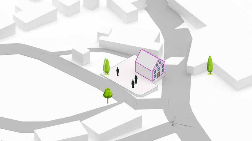
[GEMEINDEHAUS WEISSENBRUNN]
Revival and Extension of Socio Cultural Lankdmark
Gemeindehaus Weissenbrunn is a 200 year old important landmark. The main goal of the project is to revive the existing Lernershaus which serves as an important cultural point for the region. Along with it the idea is to provide a new Gemeindehaus, a part of the church of Weissenbrunn. Both the objects have been designed based on the surrounding context and visual language of the neighbouring objects. Bridging the historic with the contemporary is an important and intriguing challenge set up for the project and its execution. Konzeptionelle
Entwicklung
Weissenbrunn
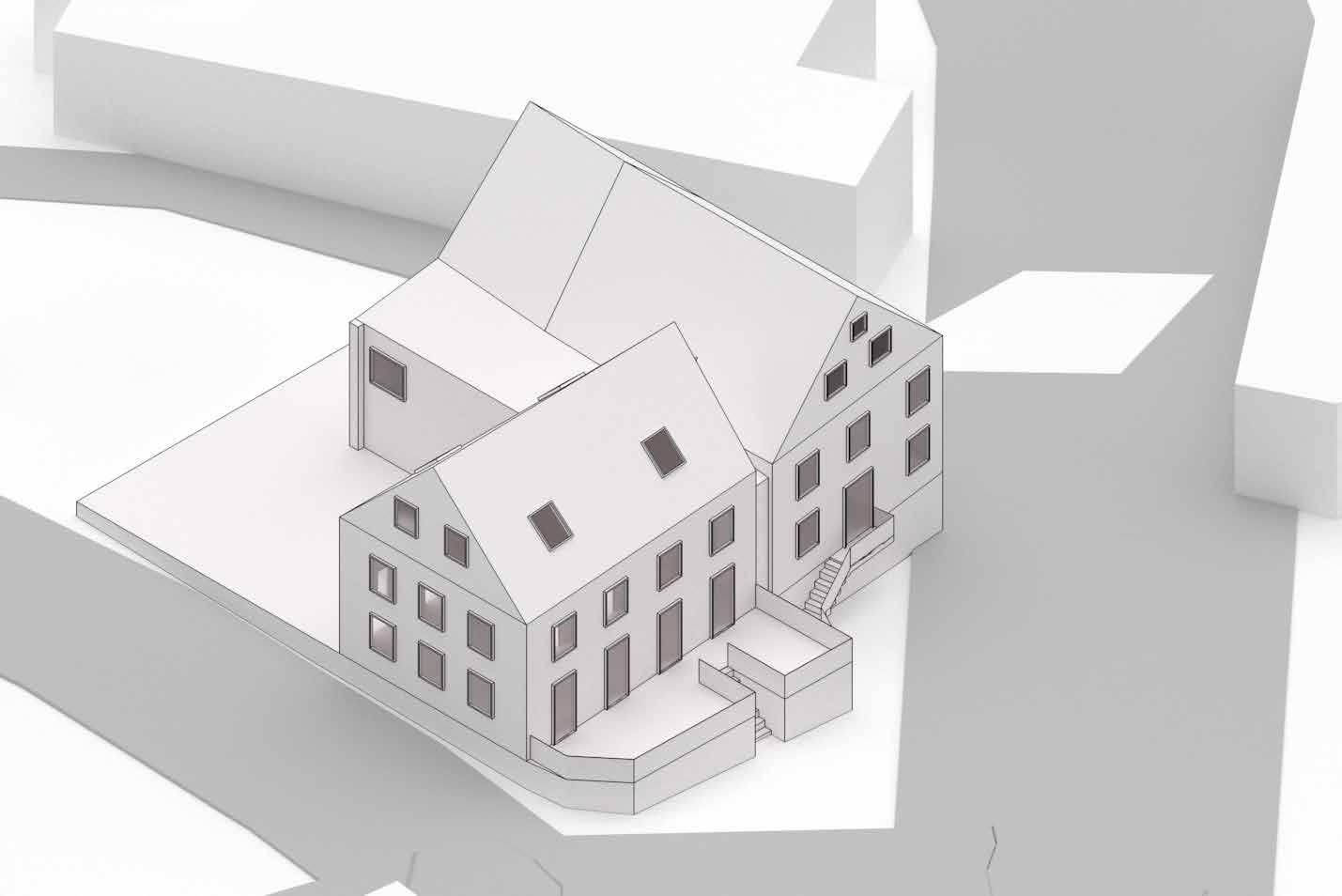
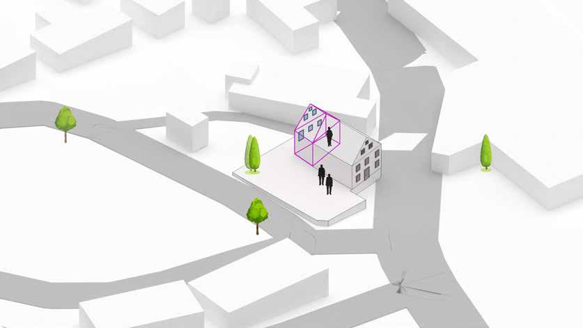
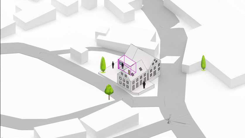
Schematic Overview
Diagram illustrates the 3 major parts of the building complex. The Lernershaus, Gemeindehaus and the Treppenhaus. The new building complex follows the visual language of the old bulding complex which results in amalgamation of historic and contemporary aesthetic techniques along with reviving the exisitng and providing a relatable outcome to the whole complex.


Existing Site: Lernerhaus


Revitalization: Lernerhaus

Extention: Gemeindehaus


Treppenhaus


Conference hall Connecting Block Barrier free environemnt
Connectivity:
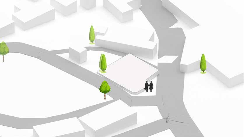
Site Layout Social infrastructure Culturall landmark Social space Social space Common space /lobby
Construction Details
Gemeindehaus: New Construction
Lernershaus: Renovation and Extention

Renovation Details
Lernershaus: Renovation and Extention
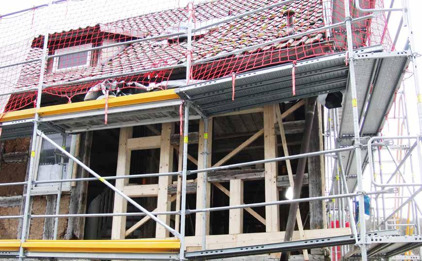
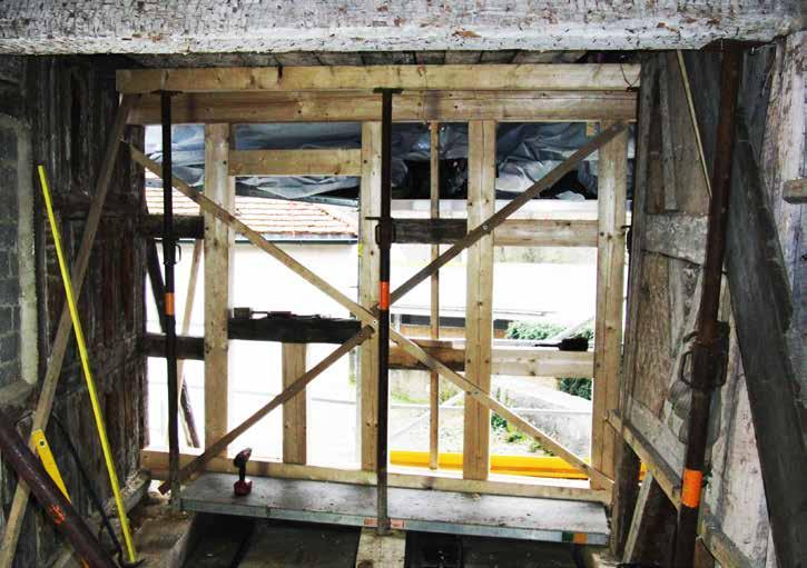
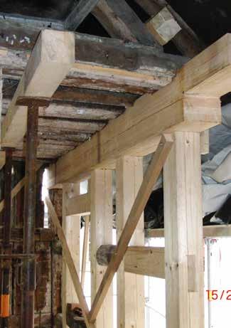 Interior renovation details: renovation of existing framework.
Renovation Details of Fachwork.
Roof Detail for treppenhaus/Lernershaus
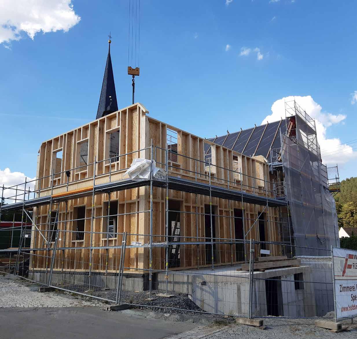
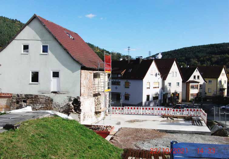
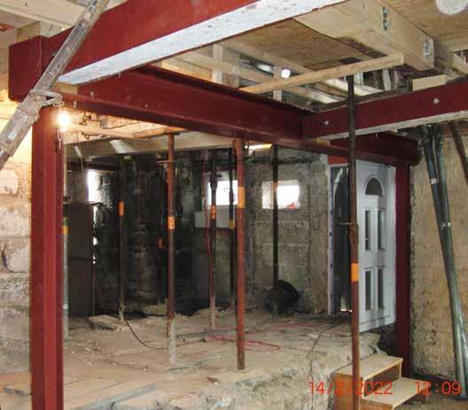
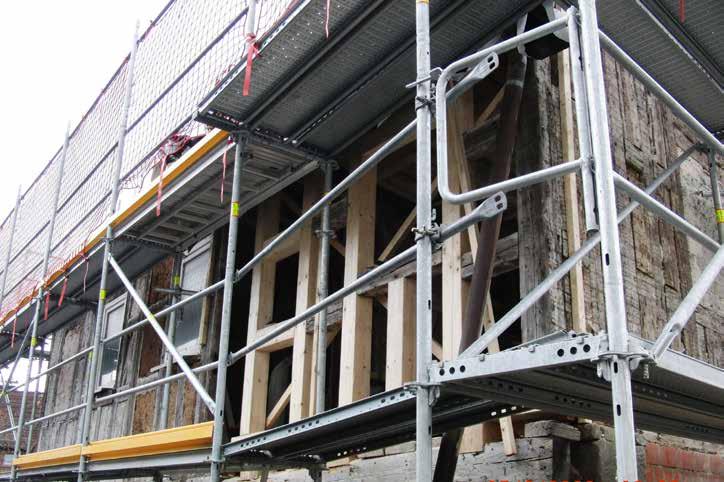
Site Execution of the Gemeindehaus along the existing Lernershaus.
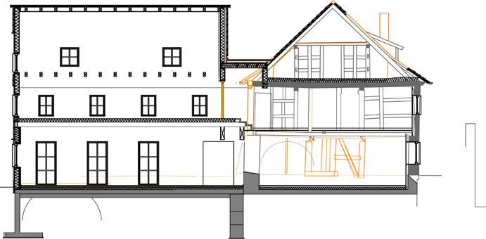
Sectional view Lernershaus and Gemeindehaus
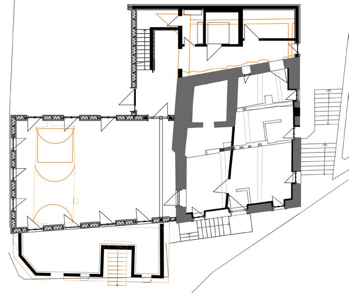
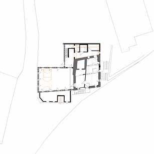
Floor plan showcasing existing Lernershaus, Gemeindehaus and extention.
Site Execution of the Gemeindehaus along the existing Lernershaus.
Interior renovation details: renovation of existing framework.
Renovation Details of Fachwork.
Roof Detail for treppenhaus/Lernershaus
Site Execution of the Gemeindehaus along the existing Lernershaus.
Sectional view Lernershaus and Gemeindehaus
Floor plan showcasing existing Lernershaus, Gemeindehaus and extention.
Site Execution of the Gemeindehaus along the existing Lernershaus.
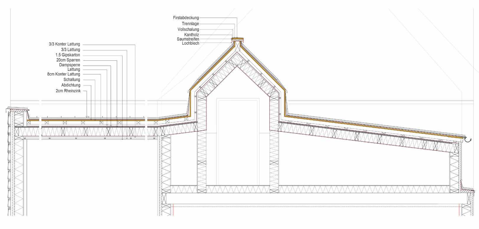
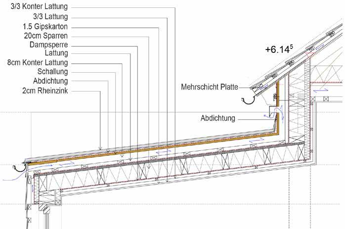
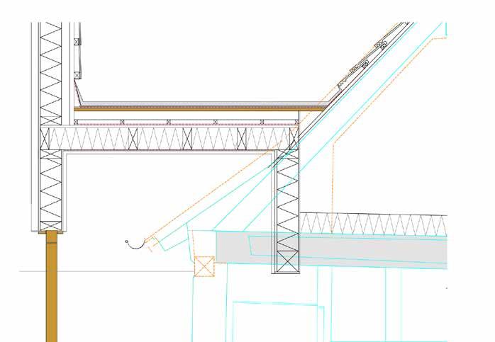
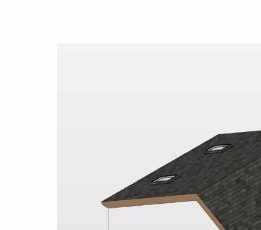
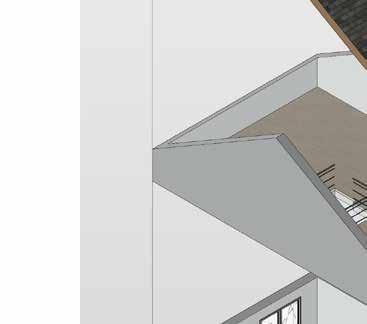
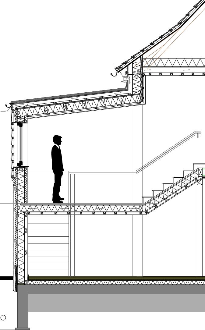
Roof Construction Details Longitudinal
Roof detail through the 3 major volumes is an important technical representation of juxtaposition of roof details of each block. Each block has been provided with separate roofs merging into single outcome. Each roof has been detailed with different varieties of materials based on the site requirement. The lernershaus and gemeindehaus follow the traditinal shingle detail belonging to the Franken region whereas the connecting spaces have been designed and detailed using Zinc metal in contruction techniques.
Roof
detail through the treppe and
old
building roof from lernershaus. Fachwork reconstruction in Lernershaus.
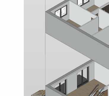
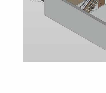
Section through the lernershaus, gemeindehaus and treppenhaus
Renovation of Residential Project in Bayern.
The project belongs to social housing project in the region. Therefore the prior requirement is to provide barrier free as well as contemporary outlook to the existing piece of work. Thus resulting conceptual proposal is graphical representation as a speculation or “story telling” in order to come up with new outcomes overcoming the challenges of the pre existing traditional building.
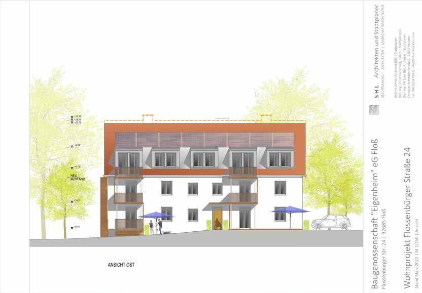
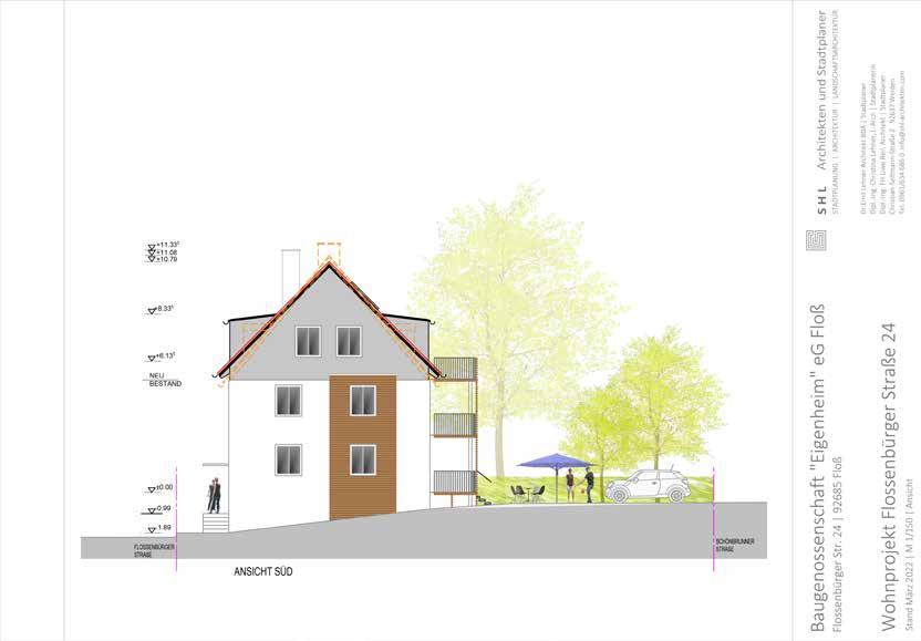
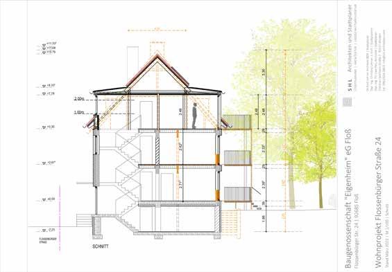
Drawings show the existing layout with details shocasing extention and demolition in order toachieve the required layout and language complimenting the genre belonging to the contemporary style. Section Elevation Elevation
[FLOSSENBURGER STRASSE]
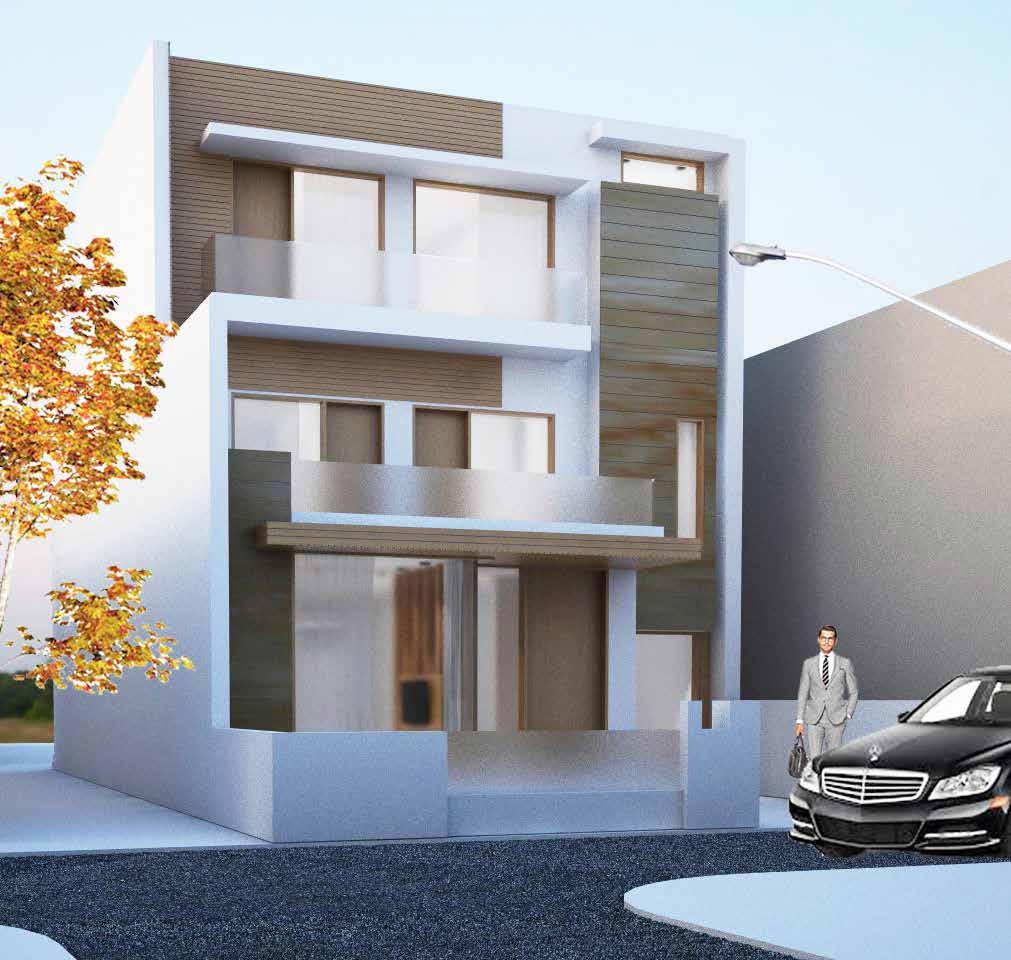
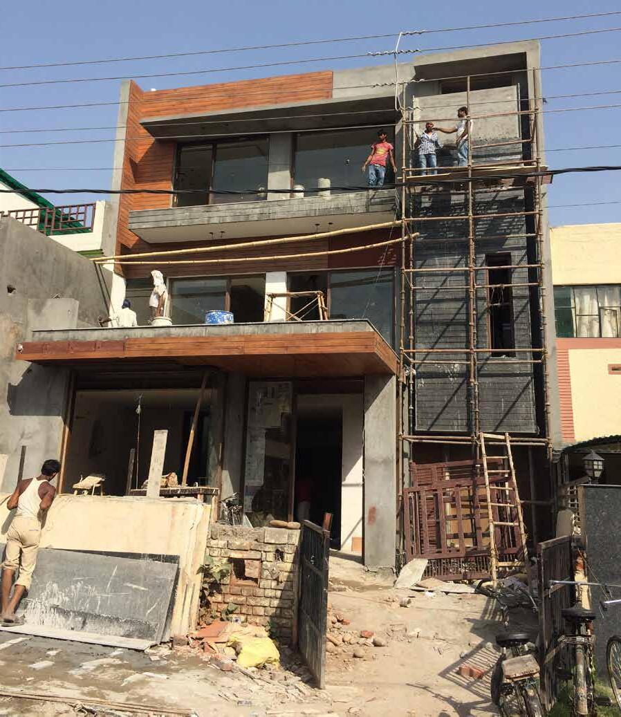
Private residence, Panchkula, India.
A residence for modern day nuclear family was the focal point for the design proposal for the project involving designing and execution of every minute detail from wall to wardrobe. The design proposal, execution and construction includes formulation of spaces based on requirements of the client and taking zoning as per bylaws and site orientation into consideration.
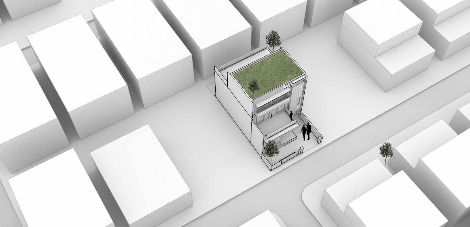


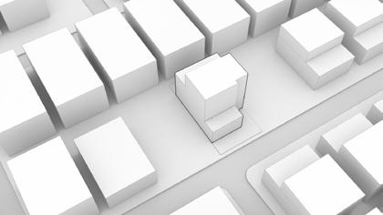

? SITE Plot size is 2722.51 sq. ft and is located in densely populated street of sector 15 panchkula CONNECTION Base massing with the required 3240.98sq ft. 3240.98sq .ft CUBOID MODIFICATION Modi cation of cuboid according to the zoning lines from the front and rear area, keeping the area limits into consideration. STACKING BASED ON REQUIREMENTS Rearrangement of spaces according to individual oor requirement and provision of terraces in relation to the context. Design Conceptualization Design conceptualization stages developed based on plot size, orientation and city bylaws. The site layout has been designed based on zoning bylaws and frame style of the house in which frame is mandatory in the front and rear elevation, also keeping in mind the permissible area limits for each floor.
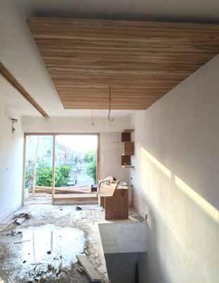
[CONSTRUE]
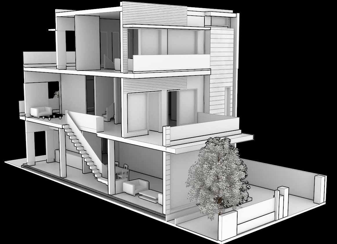
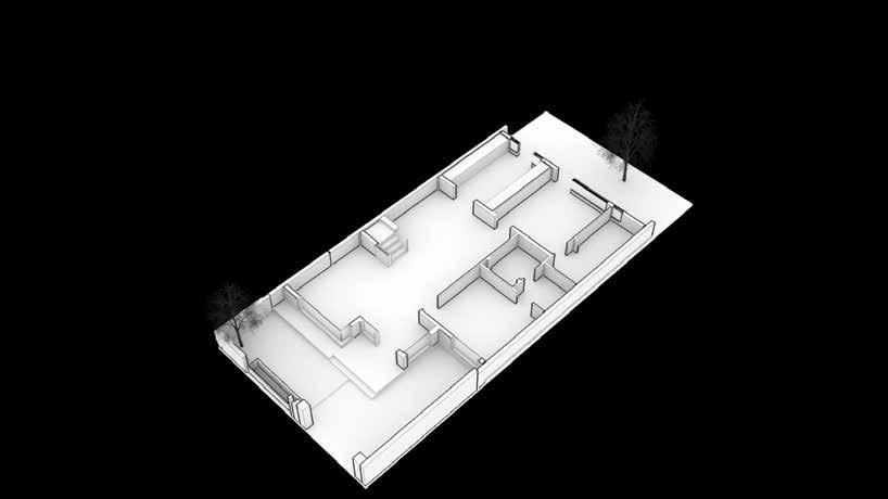
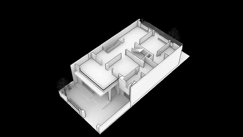
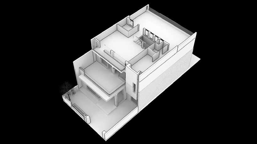
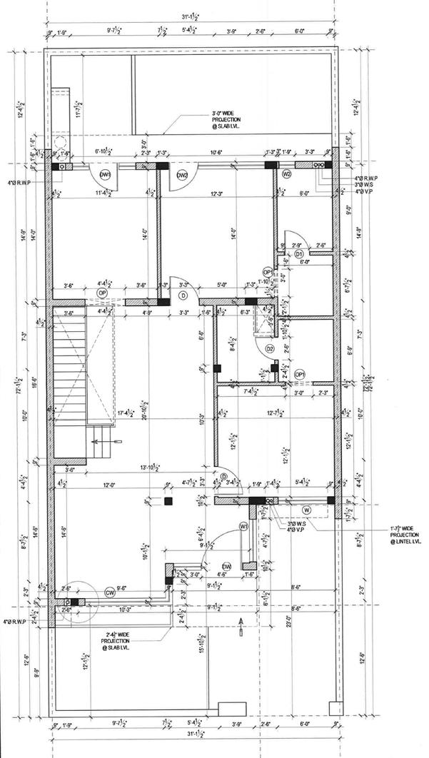
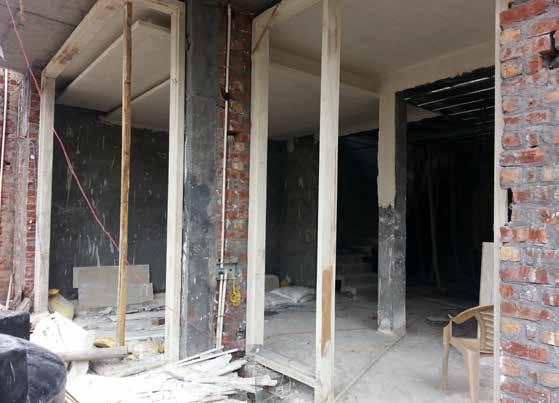
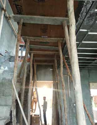
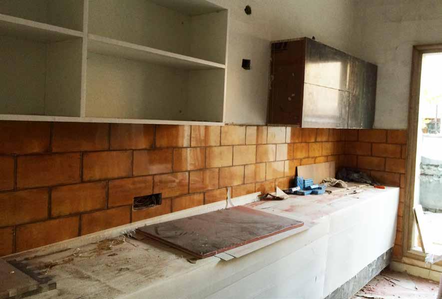
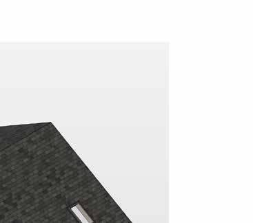
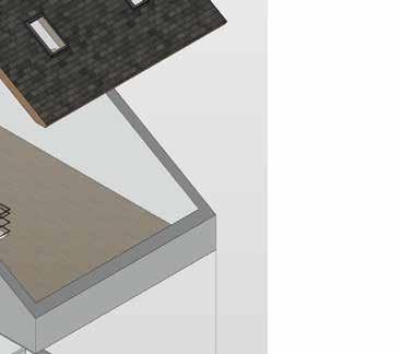
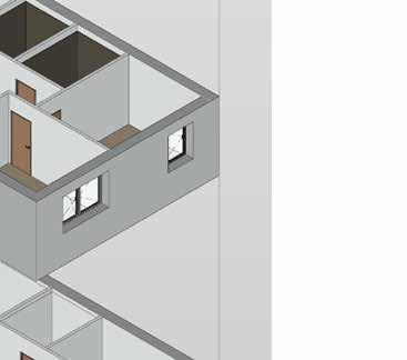
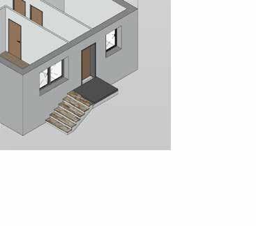
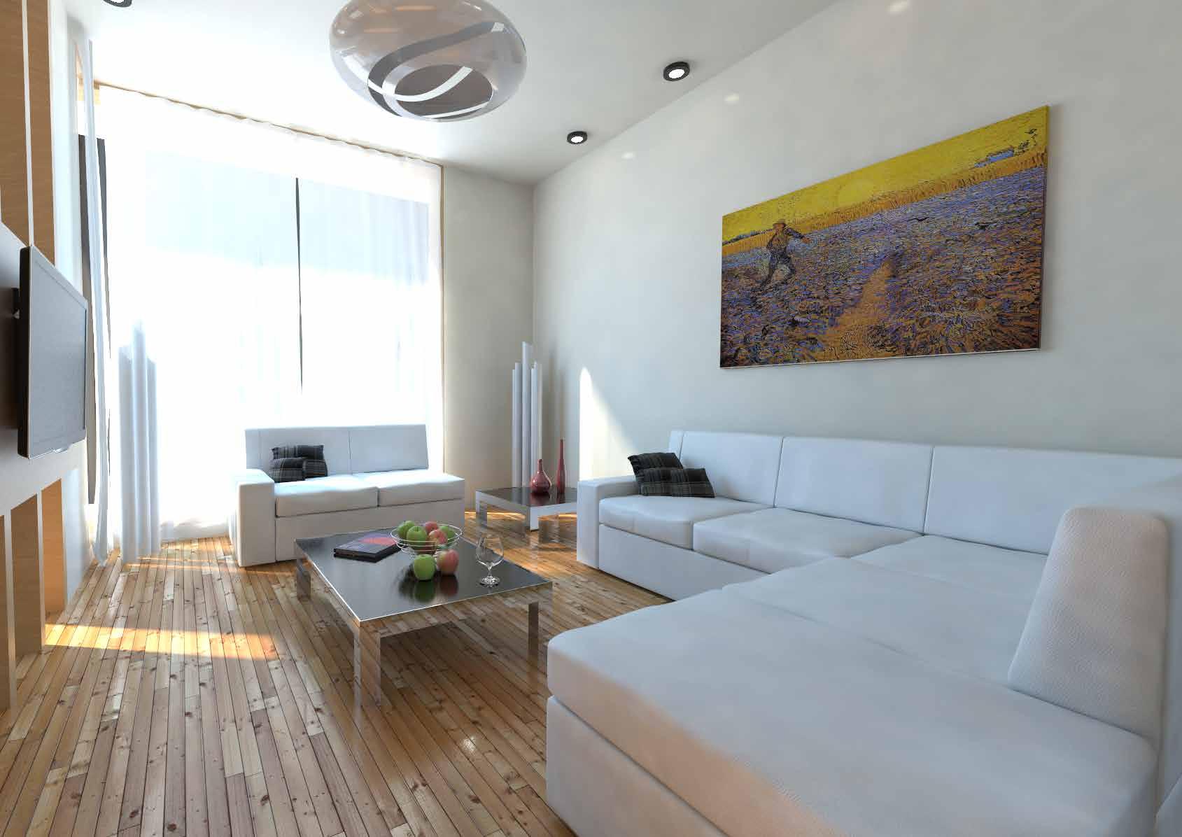
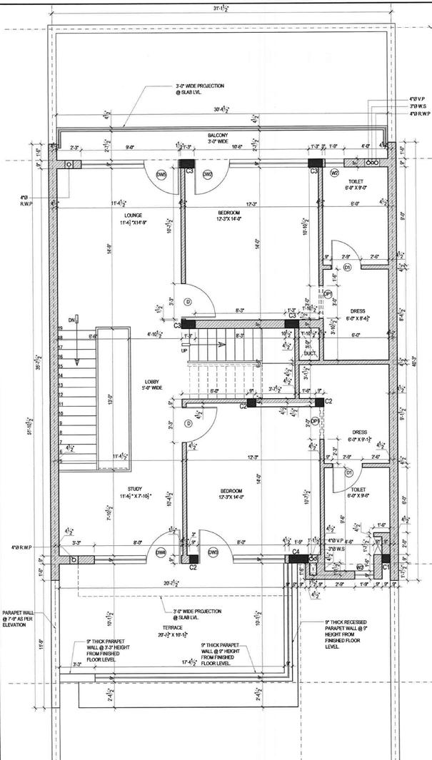
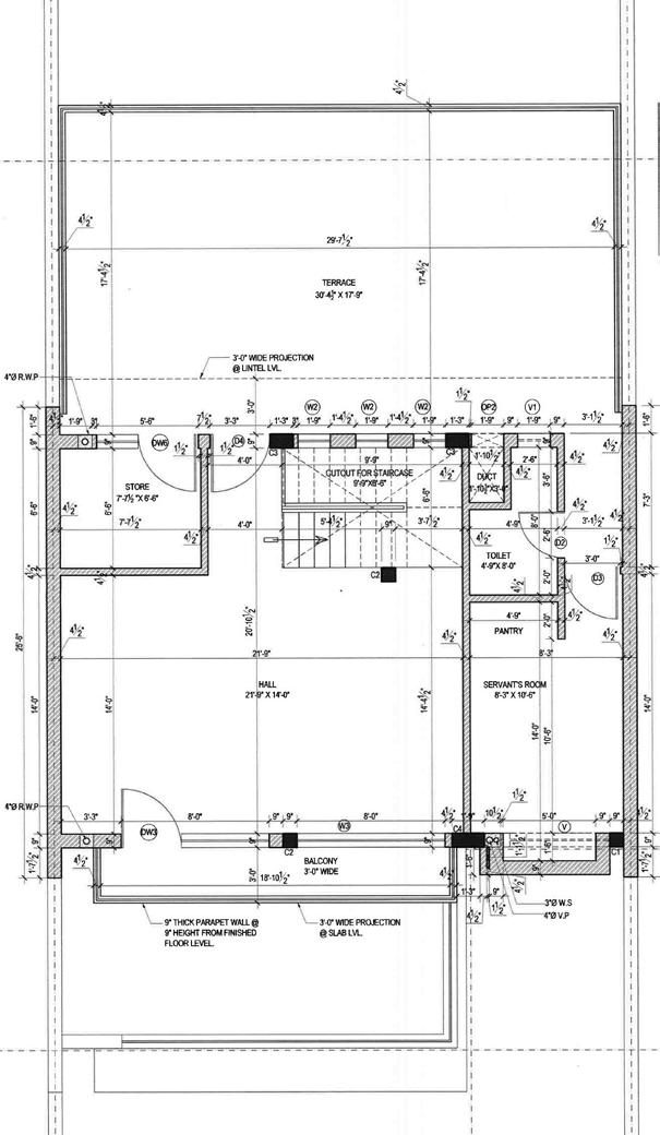
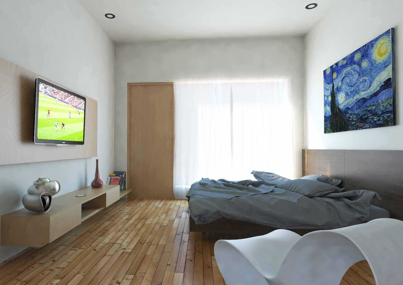
1 3 2 Detail of civil work with woodwork and ceiling of the front entrance area. Detail of kitchen interior woodwork including cabinet design along with other wall and floor finishes using tiles. Ceiling framework construction along staircase. 3 2 1 Ground Floor Working Drawing Execution and Construction Design Development Isometric views showing internal layout and cross section Isometric views with floor wise integration of spaces and other areas such as lobby as living space, bedrooms connected with balconies and terraces. Generation of spatial and visual connection i.e. working out of elevations in context with the internal spaces. First Floor View Ground Floor View Second Floor View
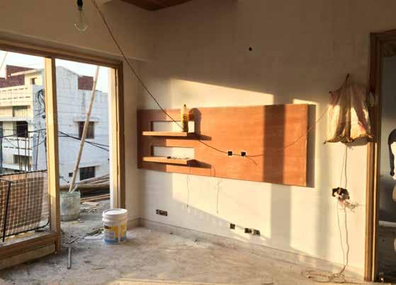
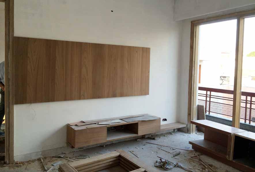
3 2 1 1 3 2 Details of interior woodwork on first floor. The woodwork has been designed according to the electrical details of all the areas. Details of bedroom interior details like lcd panels, doors, false ceiling, railings etc. First Floor Working Drawing
the
lobby area.
Furniture
details through
central
1
Second Floor Working Drawing
1 Front view of the residence with final stages of RCC work carried out for the boxing feature on the elevation. Use of wooden panels and grooving over parapets on the front face.
