


SEMESTER 2 YEAR 3, 2023
PROJECT 2 : THE ENERGISING INSTITUTE OF SUSTAINABILITY AND BIODIVERISTY.

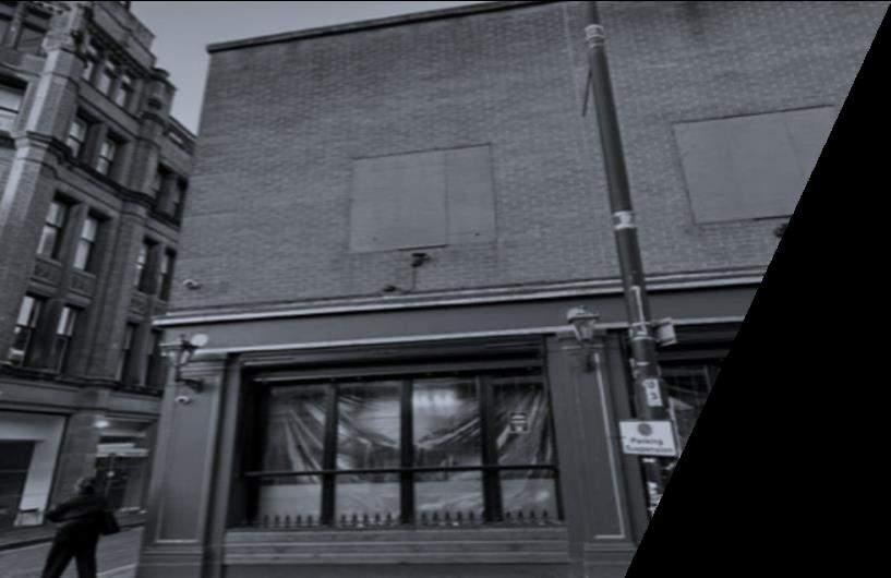
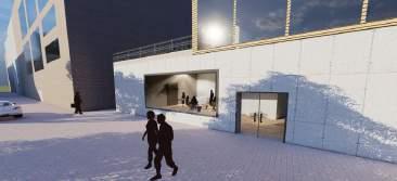
A team will be dedicated to analyse which buildings in St. Peter Square are viable in terms of location and site space for demolition and repurposing for the design portfolio 3B. The ideal building will be fitted with renewable technologies, green architecture and solar panel roofs which gather resources and conduct municipal experiments All the studies and research on Manchester City Crossing, including the solar studies, climate, population analysis on the area and the technicalities on solar trees featured in design studio 3A, will be compiled in the activities that will be held in relation to the objective of this design.
The client’s vision is to construct a leading facility in the centre of Manchester, to assist research on sustainable development, biodiversity conservation, and ecosystem management. The research centre should act as a hub for collaboration and information exchange, bringing together academics, researchers, businesses, and governmental organisations to work together to create a sustainable and biodiverse future.

The consumer perceives working with other institutions or organisations, including schools, research centres or non-governmental organisations, to utilise their expertise and resources. A specific budget and funding from other sources such as RIBA and BREEAM, will also be considered for the establishment and operation. However, the client could choose to collaborate with or seek out experts in several fields related to biodiversity and sustainability research, specialists like biologists, egologists, conservationists or climate scientists.
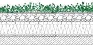
The construction of the research centre ought to place a priority on energy efficiency and minimal environmental effect. To achieve this, use of the most up-to-date sustainable design concepts, including green roofs, rainwater collecting, and renewable energy sources like solar and wind power should be made Environmentally friendly building methods and structures which are flexible and adaptable enough to fulfil changing research demands, must be used.
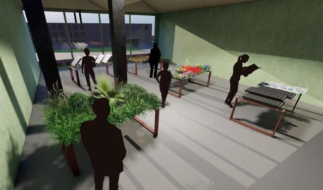
The improvement of the local ecology should be a high focus whilst the research centre is being constructed A prime example of incorporating ecological needs into the construction includes scenic spaces, like green walls that provide habitats for nearby wildlife. The facility should act as a model on how biodiversity conservation and sustainable development can coexist to benefit both the environment and future generations of humanity


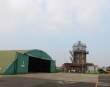
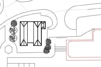
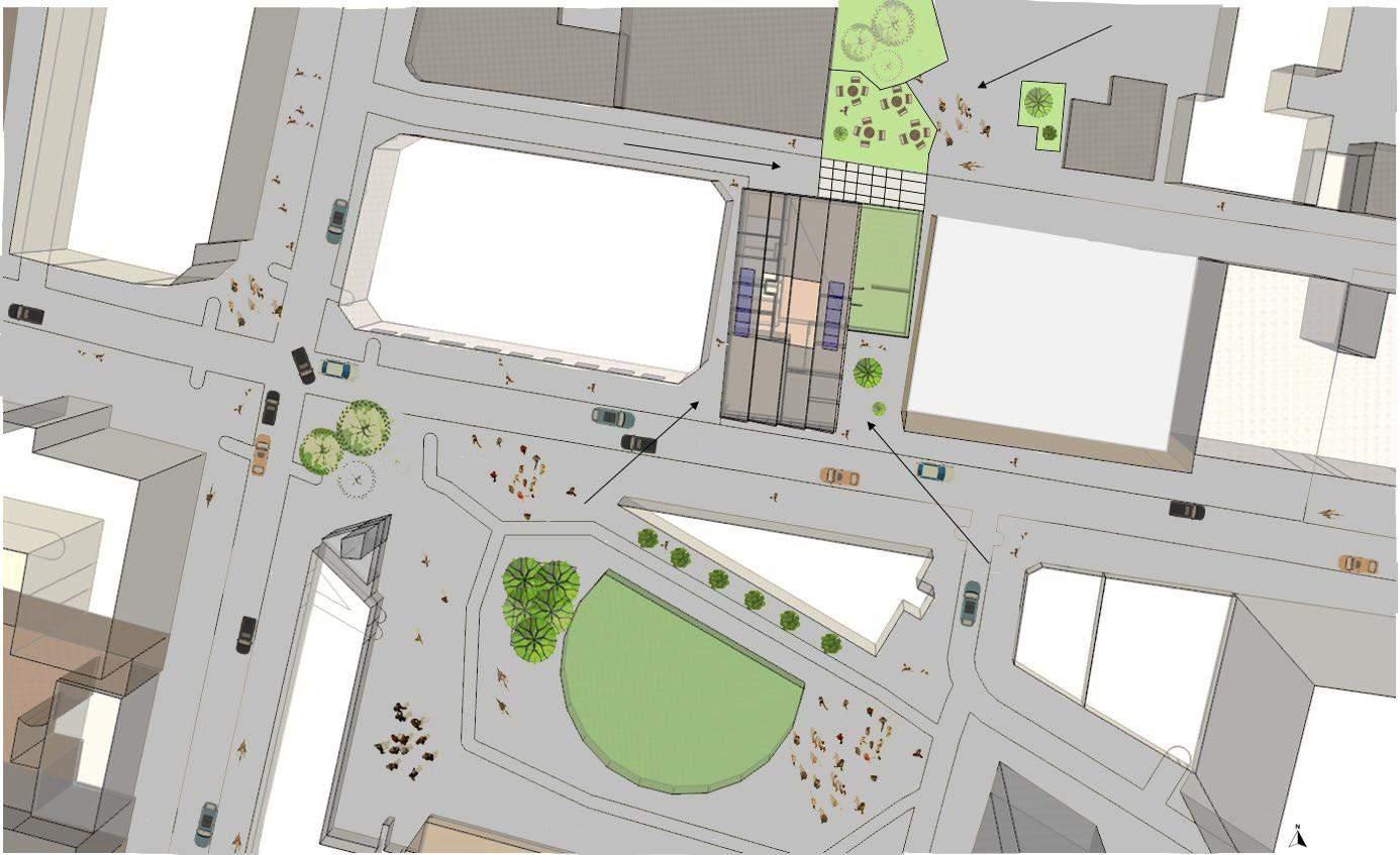
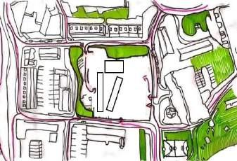
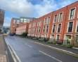
SURROUNDING BUILDINGS AND NOISE

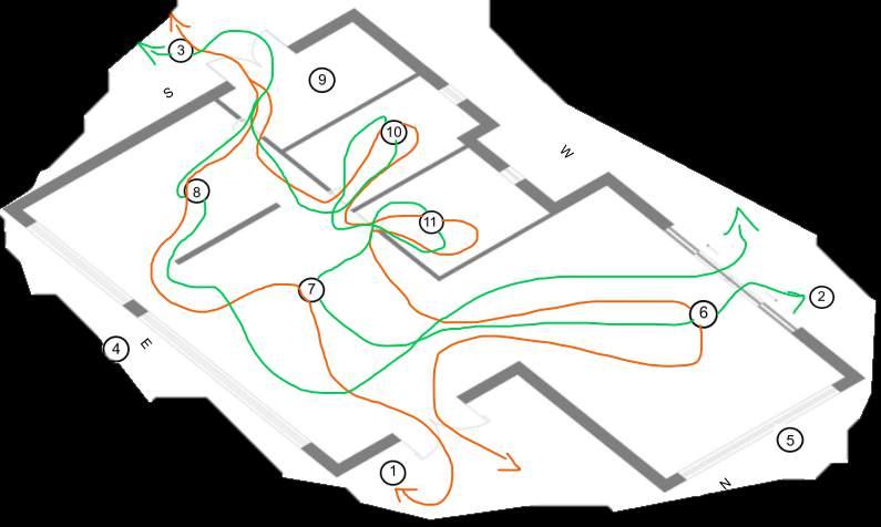
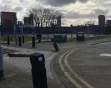
CIRCULATION
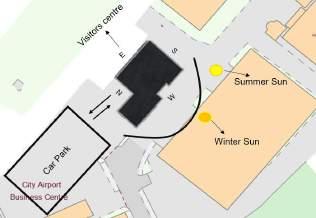
CLIMATE CONTEXT
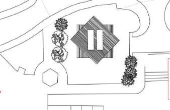
Site Location Greenway connection
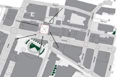
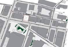
Main distributor road
Pedestrians & cycle links


Unproductive open space
Steep level change

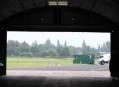
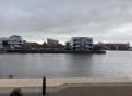
VIEWS IN AND OUT OF SITE
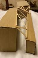
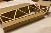
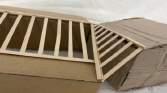
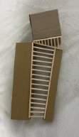
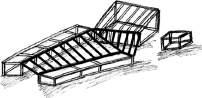
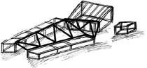
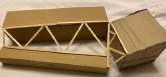
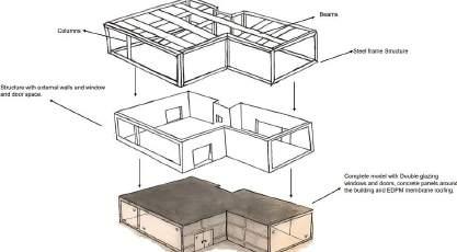
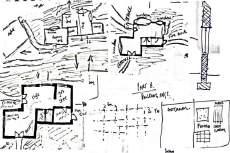
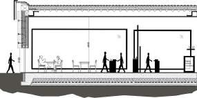
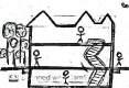
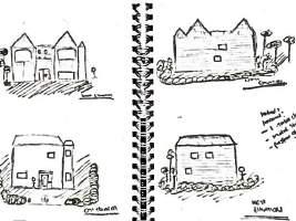
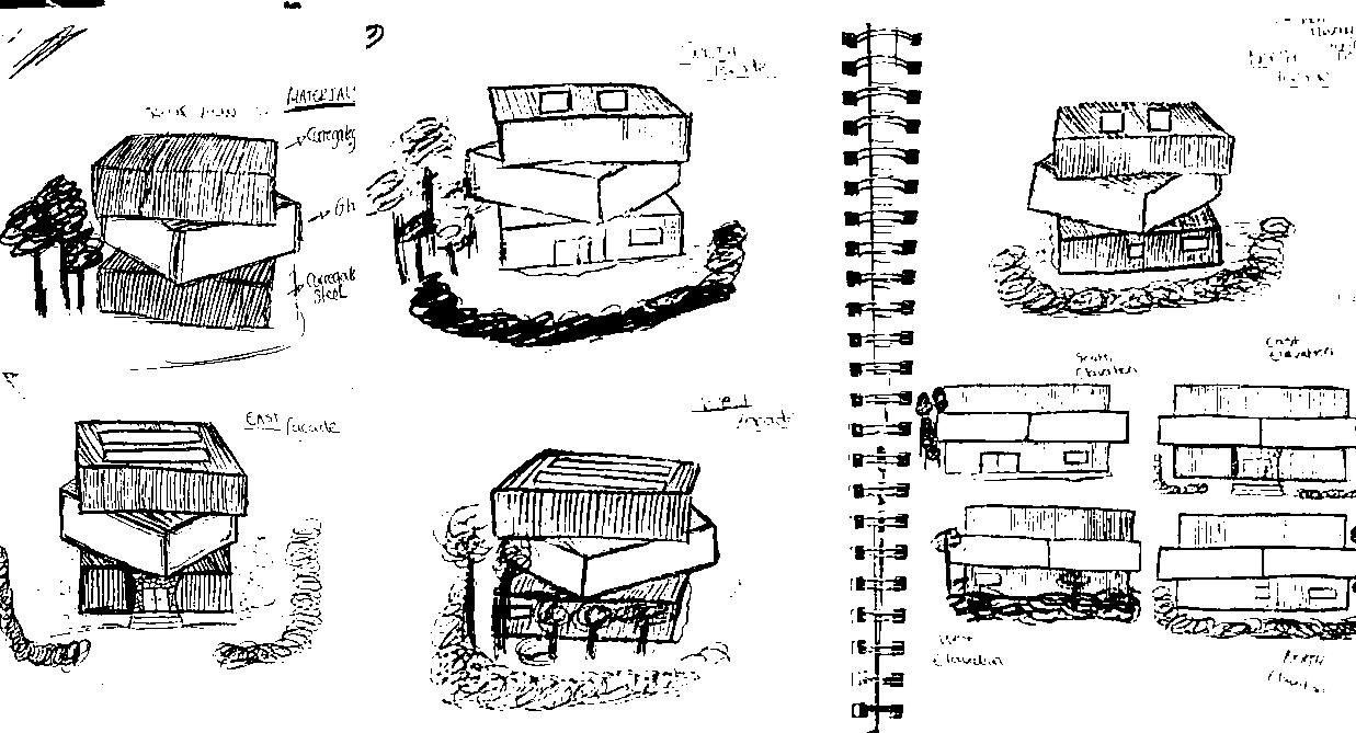
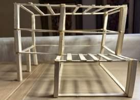
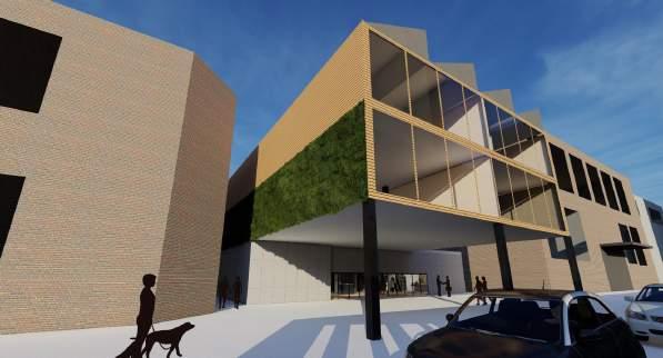
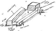
During the concept design development stage, a process of creating four distinct designs was undertaken to reach the final idea. Subsequently, the decision was made to generate 3D models to visualize and determine the most suitable design for the project. This additional effort provided a sense of assurance that the chosen cantilever style for the concept design is the most practical option.


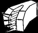

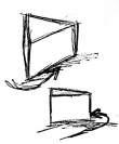
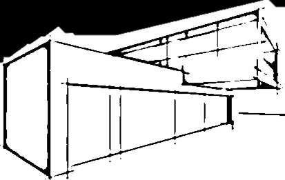


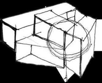


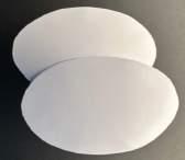

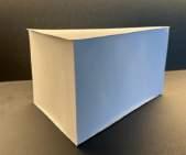
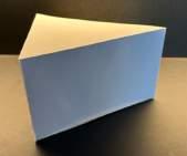


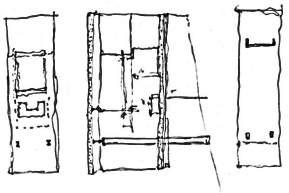


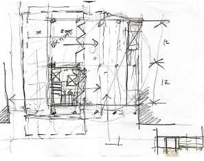


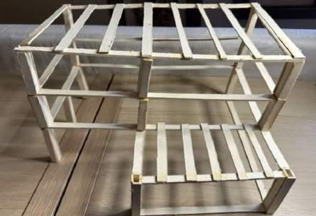
The following diagrams above showcase the structural order of the 2 storey cantilever style. The hand drawn exploded axonometric has been created into a digital model which illustrates the first layer to the designs main body which will be constructed with steel.


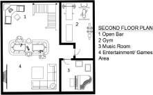
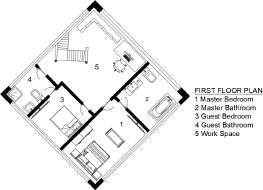
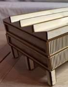
– STRUCTURAL MODEL 1:50 + FINAL MODEL 1:100


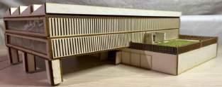


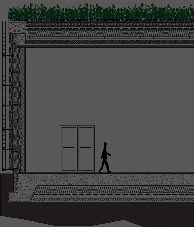
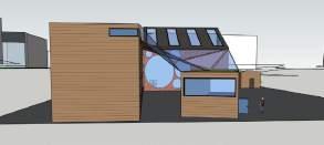
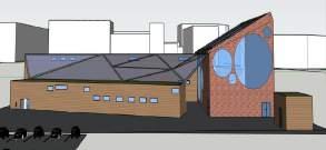
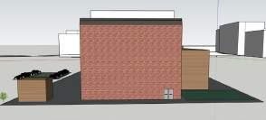
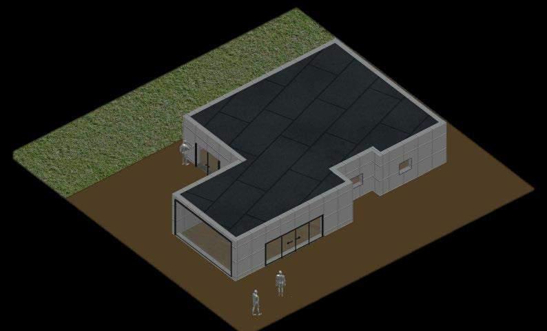
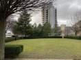
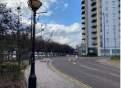
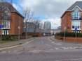
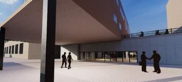
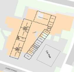
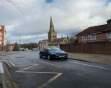
The area surrounding Peter Street is renowned for having a wide variety of residential and commercial buildings The area around the street is a centre for culture, since it is home to several well-known theatres and music venues, including the Bridgewater Hall and the Manchester Opera House, down with being easily accessible by foot, there are several tram stops and bus lines that travel down the street. In my design I have utilised the surrounding vacant space on Bootle Street, situated on the south façade of my building, transforming it into a green space addition that will mainly be used in the summer months.


Insulate Roof Panels
Z Purlins
Sawtooth Roof Steel Structure
Level Two
Timber Battens
Vertical Timber Cladding
Level One
Aluminium Window Frames
Double Glazed Glass
Waterproof Membrane
Standard System Panels
Planting Panels

Ground Level
Screed
Concrete Slab
DPM Membrane
Insulation
DPM Membrane
PV Solar Panels
KS1000RW Quadcore
Lattice Trusses Gutters


Breather Membrane Insulation
Vapour Control Layer
Insulated Plasterboard
Skim Finish
Concrete Cladding
Breather Membrane
Insulation
Vapour Control Layer
Concrete
Skim Finish
Sand Binding
Hardcore
Concrete Footing
Insulated Panel Quadcore KS1000RW
Steel Structure Insulated Panel
Gutters
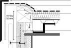
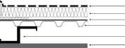
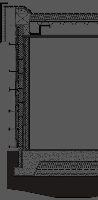
SAWTOOTH ROOF CALL OUT
Solar Panels
Stitching Screw Z Purlins

Lattice Truss


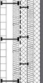
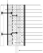
VERTICAL TIMBER CLADDING WALL CALL OUT
Vertical Timber Cladding
Breather Membrane over OSB
Sheathing

Vertical Timber Counter Battens
Horizontal Timber Battens

Stainless Steel Side Trim Irrigation System
Waterproof Membrane
Concrete Wall With Smooth Surface
Frame Connecting Panels Wedge Anchor
Standard System Panel
Planting Panels
Foundation Blockwork
3 mm Skim Finish
32.5mm Insulated Plasterboard
Vapour Control Layer
Timber Stud Wall With 120 mm Insulation
GREEN WALL CONCRETE CLADDING WALL CALL OUT
3 mm Skim Finish
Joint Sealant With Backing Rod Stainless Steel Bracket
Substrate – Concrete Wall
Vapour Control Layer
Insulation Mechanically Fixed To Substrate
Breather Membrane
CONCRETE FOUNDATION CALL OUT
Screed Concrete Slab
DPM Membrane Insulation
DPM Membrane
Sand Binding Hardcore


AN OBJECT FOR THE CITY


SEMESTER 1 YEAR 3, 2022
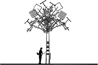
PROJECT 1 : SOLAR TREES.


BRIEF


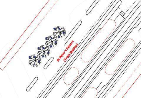
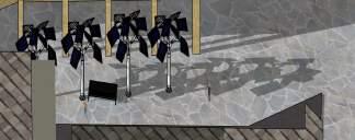
This project encompasses the creation of sketches, elevations, sections, and floor plans for 'an object in the city' that will be situated on St Peter Square

CONCEPT


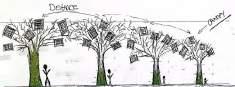
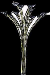
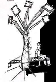
Solar trees are a commendable idea as they harness clean energy, reduce carbon emissions, and enhance urban aesthetics. They serve multiple functions such as providing shade, charging stations, and Wi-Fi hotspots, contributing to sustainable and convenient public spaces


• Power: Solar panel

• Sun friendly: yes
• User friendly: yes
• Width: 2.80 m

• Length 4.15 m


• Solar panel L x W: 0.5 x 0.4 m

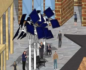

• Thickness of solar panel: 0.3 m
• Energy: 144W
• USB ports: 8
• Features: USB charging, canopy, and night illumination.


SEMESTER 2 YEAR 2, 2022
PROJECT 2 : EDUCATIONAL INSTITUTE.
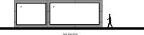
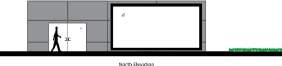
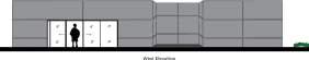
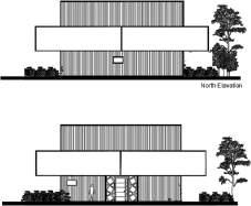
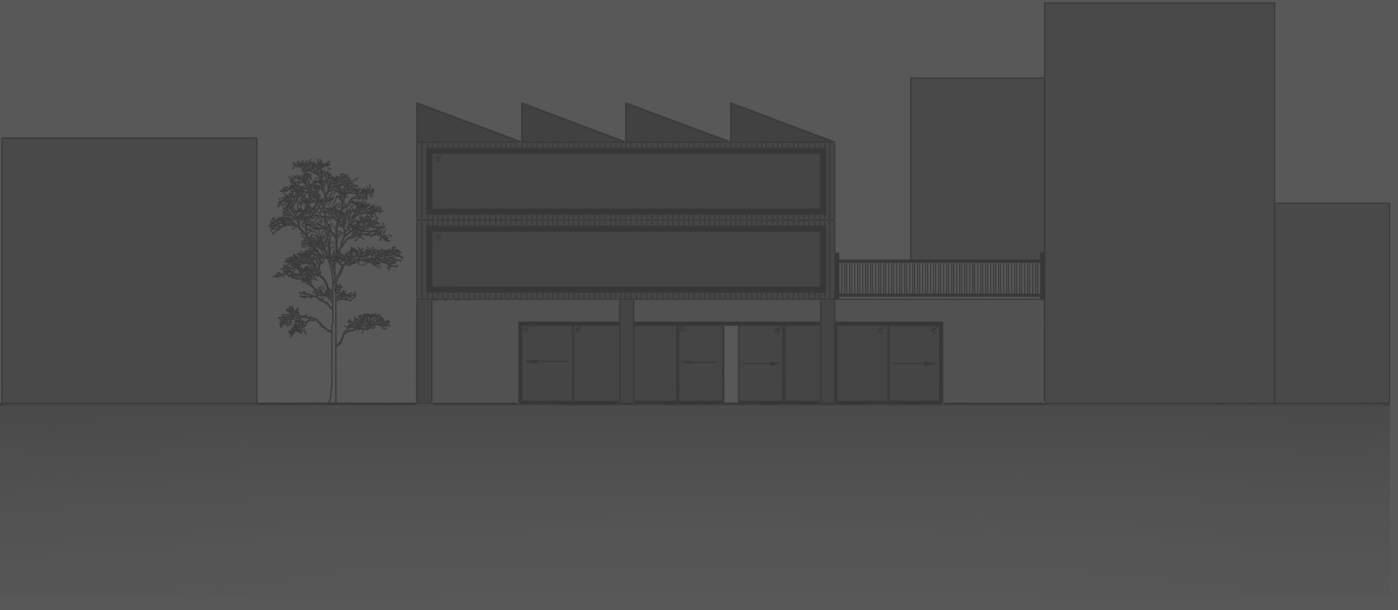
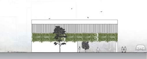
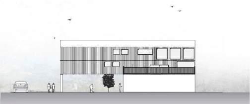
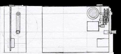
CAD ELEVATIONS


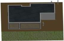
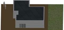
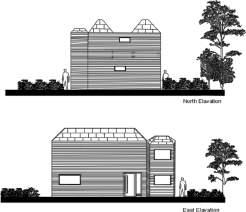
NORTH ELEVATION
BRIEF
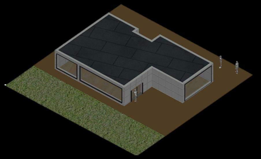
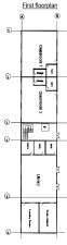
This project entails the development of sketches, elevations, sections, and floor plans for an educational primary institute situated in Salford Furthermore, meticulous consideration will be given to selecting a site that best meets the client's needs and preferences


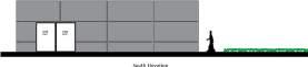
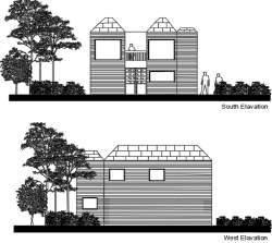
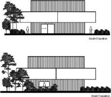
SOUTH ELEVATION
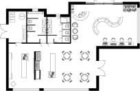
CONCEPT
The educational institute's concept prioritizes the safety of children and staff by strategically locating a central playground within the school premises, as well as high walls around Thereby minimizing the potential for any hazardous incidents or unsafe activities This design approach aims to create a secure and protected environment for all stakeholders involved.
NORTH ELEVATION