Dartmouth College Dartmouth College
Dartmouth Digital Commons
Dartmouth Digital Commons
Dartmouth College Master’s Theses Theses and Dissertations
Summer 9-26-2024
Design, Characterization, and Simulation of a 2D Dual-Rail
Design, Characterization, and of a 2D
Quantum Processor Quantum Processor
Diego Barrutia
Follow this and additional works at: https://digitalcommons.dartmouth.edu/masters_theses
Part of the Nanoscience and Nanotechnology Commons, and the Quantum Physics Commons
Design,Characterization,andSimulationofa2DDual-RailQuantum Processor
AThesis
SubmittedtotheFaculty inpartialfulfillmentoftherequirementsforthe degreeof
MasterofScience in EngineeringSciences
byDiegoBarrutiaAlta
ThayerSchoolofEngineering GuariniSchoolofGraduateandAdvancedStudies
DartmouthCollege Hanover,NewHampshire
September2024
ExaminingCommittee:
Chairman_______________________ MattiasFitzpatrick,PhD
Member________________________ LauraRay,PhD
Member________________________ JifengLiu,PhD
F.JonKull,Ph.D. DeanoftheGuariniSchoolofGraduateandAdvancedStudies
Member________________________ RufusBoyack,PhD
Abstract Bosonicsystems,suchasthree-dimensional(3D) � 4 coaxialcavitiesandtwo-dimensional (2D) � 2 coplanarwaveguide(CPW)resonators,arequantumharmonicoscillatorsthat encodeinformationinphasespace,o↵eringahardware-e�cientroutetowardquantum errorcorrectionandsimulationinsuperconductingcircuits.Inthisthesis,wepresent thedesign,characterization,andsimulationofadual-railprocessorconstructedwith a2D � 2 coplanarwaveguideresonators,demonstratingapercenterrorbetweenexperimentalandanalyticalresultswithinarangeof3.31%-13.16%.Theanalyticalresults exhibithighprecisionbutloweraccuracyrelativetoexperimentalmeasurements.By integratingbothclosed-sourceandopen-sourcesoftwaretools,wedevelopane�cient workflowforextractingcriticalsystemparametersandsimulatingquantumdynamics. Ourapproachprovidesinsightintoadesignlayoutofafullyplanardual-railarchitecturetocontributeinthedevelopmentofscalable,fault-tolerantquantumprocessors.
Acknowledgements IarrivedatThayerSchoolofEngineeringwithlittlelabexperience:Ididnotknow howtouseavacuum,mountaqubit,orwireRFequipment.Inpursuingthework describedinthisthesis,Ilearnedthroughtheexamplesetbyotherotherlabmembers, notjustthesetechnicalskills,buthowtoworkinaspiritofcollaborationandshared success.IthinkthiscollaborativelabcultureisthemostvaluablethingItakeaway frommyexperiencehereandforthatIthankyouall.
Iwouldliketofirstthankmyadvisor,Prof.MattiasFitzpatrick,forhisguidance andvision.Mattiasleadsbyexample,andisanexcellentrolemodelinresearchand life.Hisoftenreminderon polishingyourdata hasstronglyshapedhowIapproach problemsbothinresearchandoutsidethelab.DoingphysicswithMattiashasbeen alotoffun.Ihadthepleasureofworkingdirectlywithhimon,amongotherthings, thefirstqubitreadoutsbeingdoneinFitzLabearlySpring,aprojectwhichwasfun andexcitingandhighlyrelevanttofutureworkdescribedinthisthesis.Forthese learningexperiences,Iamdeeplygratefulandhonoredtohavehadtheopportunity tolearnfromandworkwithMattiasthroughoutmytimeatThayer.
WhenIfirstjoinedFitzLab,JuanSebasti´anSalcedoandAlexCarneymeetme withkindnessandencouragedmycuriousnature.Inmyearlydaysinthelab,I struggledtouseRFequipmentalongwithunderstandingthetheoryofdissipation andcoupling.Theirnever-endingpatienceinexplainingeachcomponentofanexperimentalsetupallowedmetounderstandtheworkofthisthesisatadeeperlevel.
Icannotthankmylabmate,ChrisWang,enough.Heisnotonlyanexceptional researcherbutalsoaconstantsourceofsupportandmentorship,alwaysencouraging theteamtodeepenourunderstandingofourwork.Hisguidancewasinvaluable, particularlyduringourworkwiththedesignrulecheckusingtheCalibresoftware, whichdemandedHerculean-likee↵ort.Hisunwaveringdedicationplayedasignificant roleinthefabricationstagesofthisproject.
Iwouldliketodedicatethisthesistomyfamilymembers:myparentsWalterand Araceli,myoldersiblings,andtherestofmyfamilyinLima,Per´u.Myfamilyhas helpedmebelieveIamcapableofanythingthroughtheirloveandencouragement, andIalwaysstrivetomakethemproud.
4.1.1Non-DrivenEvolutionwith
4.1.2DrivenEvolutionwith
4.2.1VacuumStatePreparation.....................88
4.2.2CodeWordsPreparation......................92
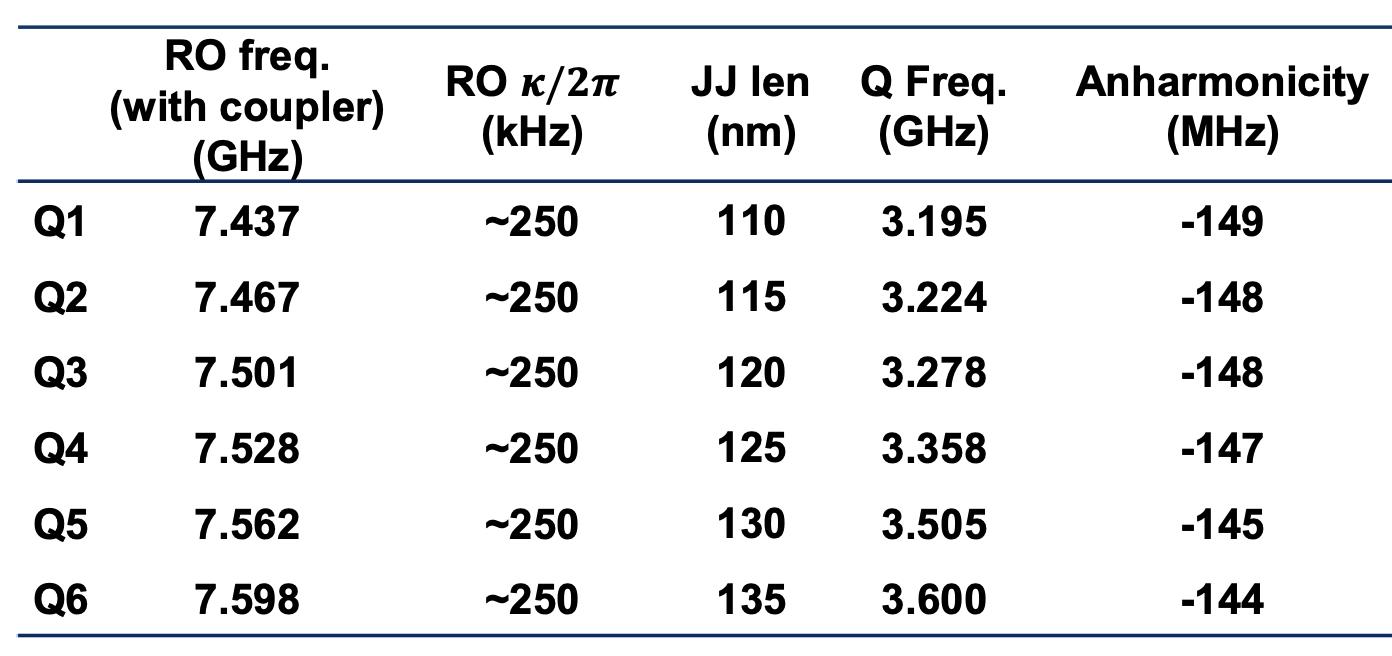
ListofTables 3.1Measuredparametersforsixtransmons,includingROfrequencies,couplingrates,qubitfrequencies,andanharmonicities...........56
3.2Circuitdesignparametersfortheauxiliarytransmonfordual-rail1 Transmon1,auxiliarytransmonfordual-rail2 Transmon2,andcouplertransmonbetweendual-rail1anddual-rail2 Coupler......74
3.3Hybridizedmodesofthepairofdual-rails,withnon-hybridrizedmodes ofdual-railcavityqubitsshowninparentheses..............74
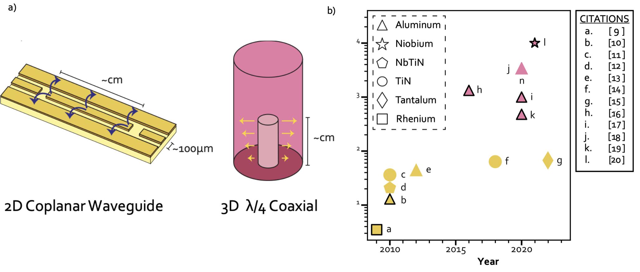
ListofFigures 1.1Adaptedfrom[8].Designsofsuperconductingresonatorsandtheir lifetimes.(a)Illustrationsoftwopopularresonatordesignsinbosonic cQED,withindicationsoftheirapproximatesizesandelectricfielddirection.(b)Aselectedcollectionofresonator T1 lifetimesforthetwoillustratedresonatordesignsextractedfromtheliterature.Thelifetimes ofresonatorshavebeensteadilyincreasingoverthelast15yearsdueto theengineeringofmaterialsandgeometries.Theshapeofthepoints indicatesthesuperconductingmaterial,andthecolorcorrespondsto theadjacentdiagrams.Wehighlightstudiesthatsuccessfullyintegrate oneormorenonlinearcircuitswithablackborder.References:CPW: [9,10,11,12,13,14,15],3D � 4 coaxialcavity:[16,17,18,19,20]..3
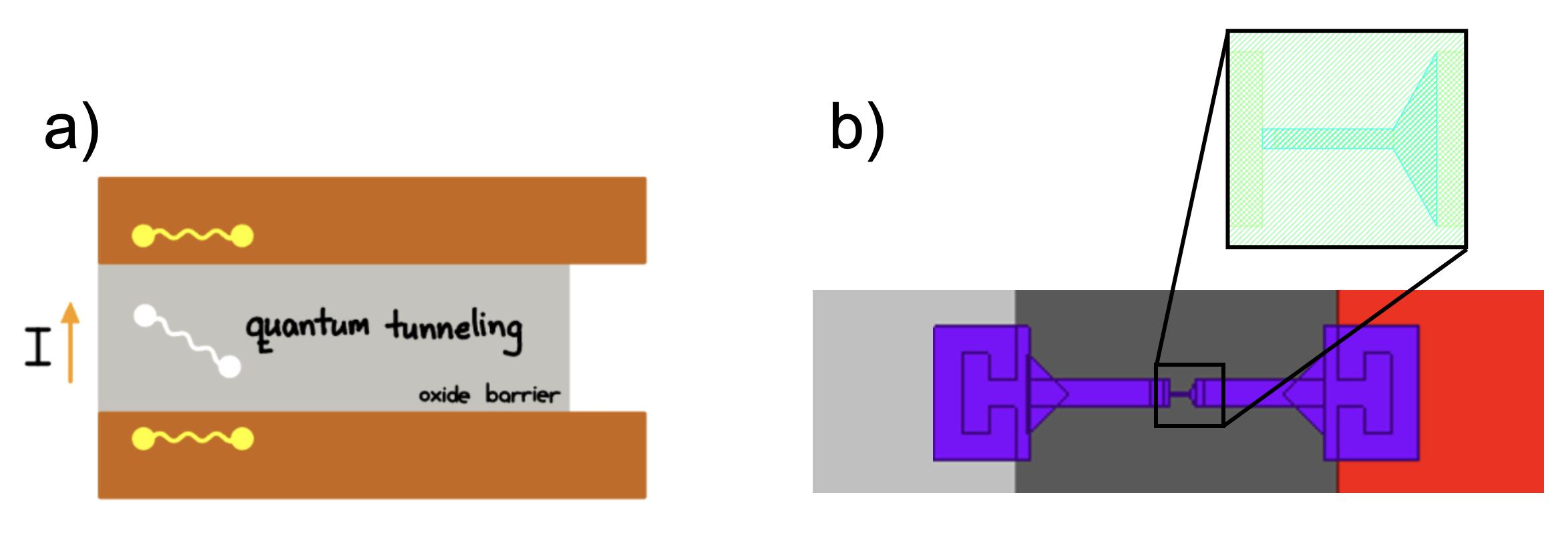
2.1IllustrationofaJosephsonjunction.(a)Cross-sectionalviewshowing quantumtunnelingacrosstheinsulatingbarrier(oxidebarrier)sandwichedbytwoelectrodes.(b)Topviewofashadow-evaporatedDolan BridgeJosephsonjunctioninbetweentwoaluminumlayers(greyand red).Thequantumtunnelingoccursinthenarrow,finger-stylestructure,showninthezoomed-inarea....................10
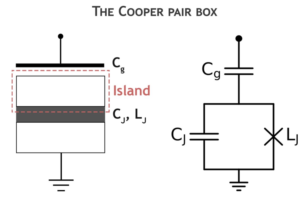
2.2SchematiccircuitrepresentationofaCooperpairbox.Theisland isseparatedfromtherestofthecircuitbyacapacitor Cg andthe Josephsonbarrier.............................13 x
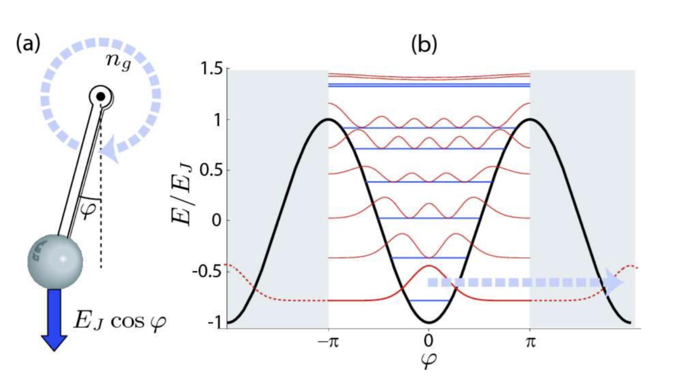
2.3Adaptedfrom[54].TheCooperpairboxisanalogoustoacharged, sti↵-rodquantumrotorinaconstantmagneticfieldrepresentedby ng .Therotor’spositionisdeterminedbythephase ',anditsangular momentumisdescribedbythediscreteoperatorˆ n...........14
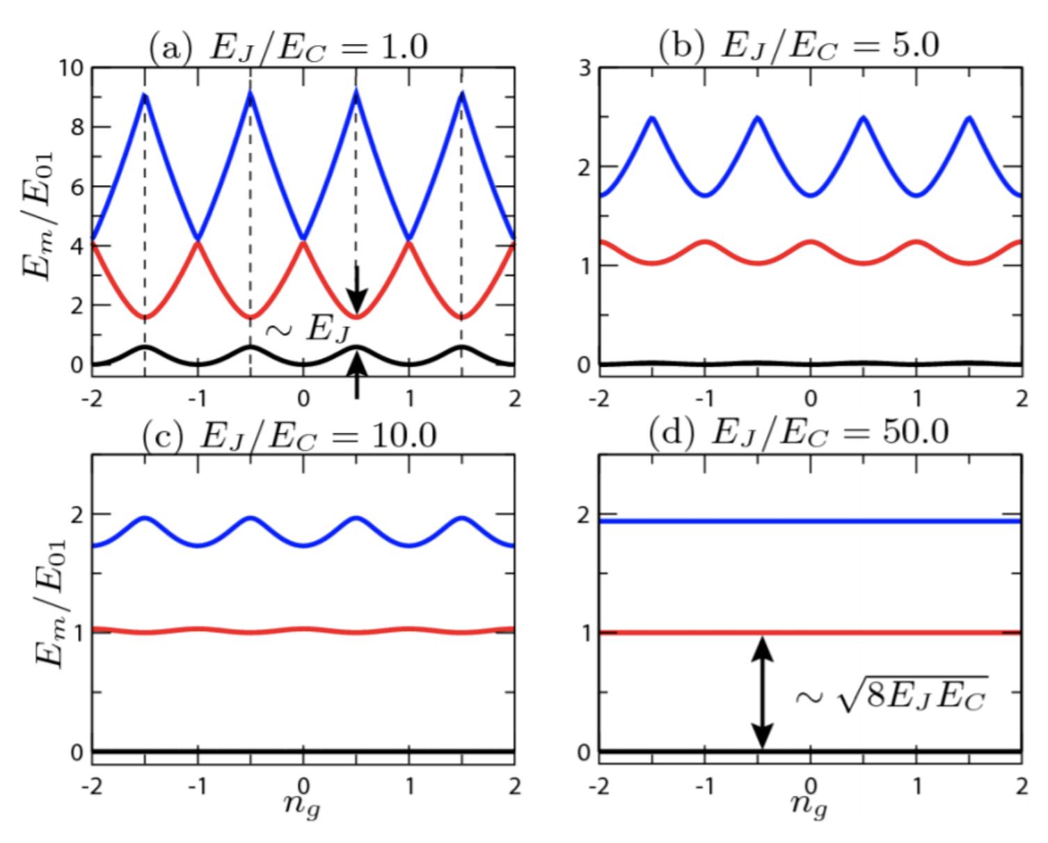
2.4Adaptedfrom[54].Thisfigureillustratestheenergylevelsfordi↵erent ratiosof EJ /EC .Increasingthisratio,achievedbyshuntingtheCooper pairboxwithalargecapacitance,reducesthestrongdependenceon gatebias ng andthusminimizessensitivitytochargenoise.Thearrows in(a)indicatethesweetspot.Theregimedepictedin(d),where EJ � EC ,isknownasthetransmonregime..............17
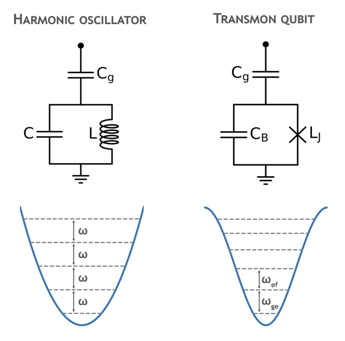
2.5Comparisonoftheenergylevelspacingbetweenaharmonicoscillator andatransmonqubit.Theharmonicoscillator’squadraticpotential resultsinequidistantenergylevels,allseparatedbythesameenergy, whichmakesitunsuitableforuseasaqubit.Incontrast,thetransmon qubit,withitscosinepotential,hasvaryingtransitionenergiesbetween subsequentenergylevels.Thisvariationallowsforprecisecontrolover individualtransitionsbetweentransmonstates.............18
2.6TheBlochsphereforageneralqubit.Thebluecirclesindicatethe sixcardinalstates: {|0i , |1i , |+i , |�i , |+ii , | ii}.Thepurplelines indicatethepolarangle ✓ andtheazimuthalangle �..........25
2.7Lorentzianshapeofthequbitspectrum.Thelinewidth � arisesfrom thedephasingrateandisdefinedbythefull-width-half-maximum(FWHM) ofthespectrum...............................31
3.1 TransmonCross:Transmonwithadjustabledimensions.........36
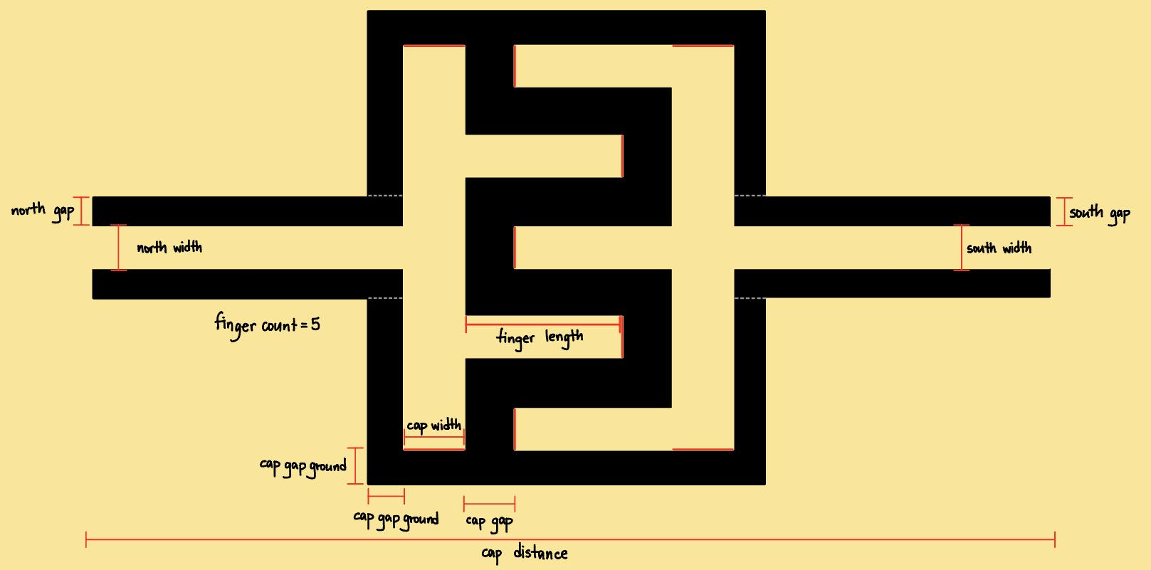
3.2 CapInterdigital:Interdigitalcapacitorwithadjustabledimensions.36
3.3CreatingaDesignPlanarobjectandinitializingitsGUI........38
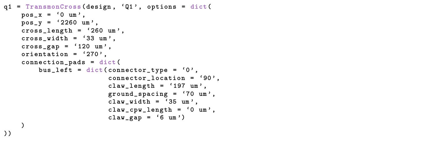
3.4Metalcodeforgeneratinga TransmonCross...............40
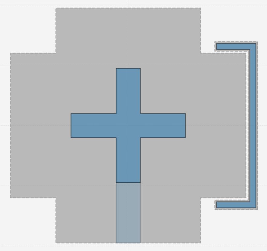
3.5 TransmonCross designinMetal......................40
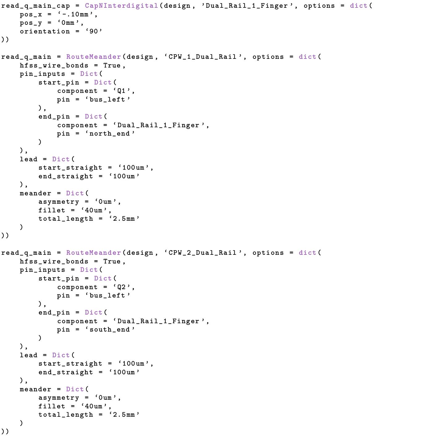
3.6Metalcodeforgeneratingadual-railsystemcoupledtotwoauxilliary TransmonCross...............................41
3.7Dual-railcoupledtotwo TransmonCross showninMetalGUI.....42
3.8Metalcodeforsettingupandrunningasimulationforadual-rail systeminHFSS..............................45
3.9(a)PlotsoftheeigenmodesobtainedusingHFSSforthedualrailchip design,showcasingthedistributionofelectromagneticfieldsforte two TransmonCross andthetwo RouteMeander.(b)FrequenciescorrespondingtoeachresonantmodefromANSYSHFSS.Both TransmonCross hasJosephsonJunctionwithinductanceof10nHandhavealmostidenticalresonantmodeasreportedinMode1andMode2.The500MHz di↵erencebetweenthesetwomodes,despitethedual-railshavingthe sameresonatorlengthandgeometry,istheresultofhybridization.(c) Illustrationofthefirstharmonicmodeforanopen-endharmonicoscillator,highlightingthedistributionofnodesatthecenterpointand antinodesattheopenendofthelengthharmonicstructure......45
3.10CodetoinitializeANSYSQ3Dforcapacitanceextraction.......48
3.11Methodoverview.(a)Illustrationofthesingledual-railsystem(partial,not-to-scale).Left: TransmonCross 1(purple)withHamiltonian
ˆ H0 connectedtoCPWwithHamiltonian ˆ H1 .Right: TransmonCross 2(orange)withHamiltonian ˆ H2 connectedtoCPWwithHamiltonian
ˆ H3 .Thelayoutisdividedintosubsystemsandcells.(b)Example simulationmodelofcell0 andcell1 withsimulationmesh.Thecells includequbitpads B0 and B2 ,CPWcouplerfingers B1 and B3 ,and thegroundsegment G consideredforthecapacitancematrix.(c)Partialschematicofthecomposite-systemnetworkshowingnodesand elementsofcell0 andcell1 ,andtheirconnectionstoneighboringcells. Nodesarecapacitivelycoupledbyafully-connectedgraph(thickline). AJosephsonjunctionconnects B0 to G and B0 to G.(d)Depictionof dressedsubsystemsasbuildingblocksandtheirinteractions,described byHamiltonians ˆ H01 , ˆ H03 , ˆ H12 , ˆ H13 ,and
3.12CodetosetupANSYSQ3Dandextractcapacitancematrix......50
3.13 Q1 capacitancematrix,withvaluesexpressedinfF...........50
3.14CompositesystemconstructionforonetransmonscoupledbyaCPW.52
3.15Criticalparametersprintedfrom hilbertspace object.........53
3.16CompositesystemHamiltonianinGHz..................54
3.17Variablestouseintheequations.....................54
3.18Pythonfunctionsforcalculating �q,r , gq,r ,and Cr ............55
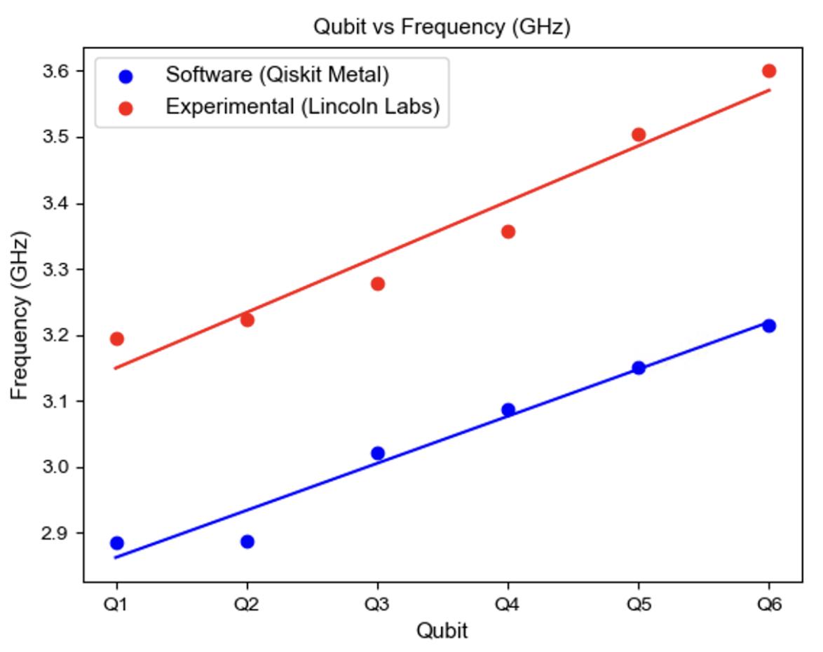
3.19Experimental(red)vsanalytical(blue)transmonfrequencyresultsfor apre-characterizedquantumprocessorhostingsixtransmons Q1, Q2, Q3, Q4, Q5, Q6................................57
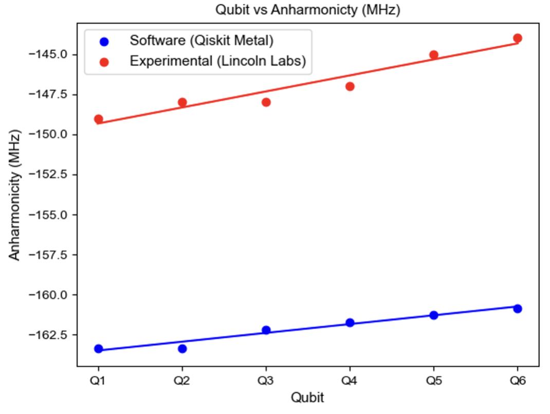
3.20Experimental(red)vsanalytical(blue)trasmonanharmonicitiesresultsforapre-characterizedquantumprocessorhostingsixtransmons
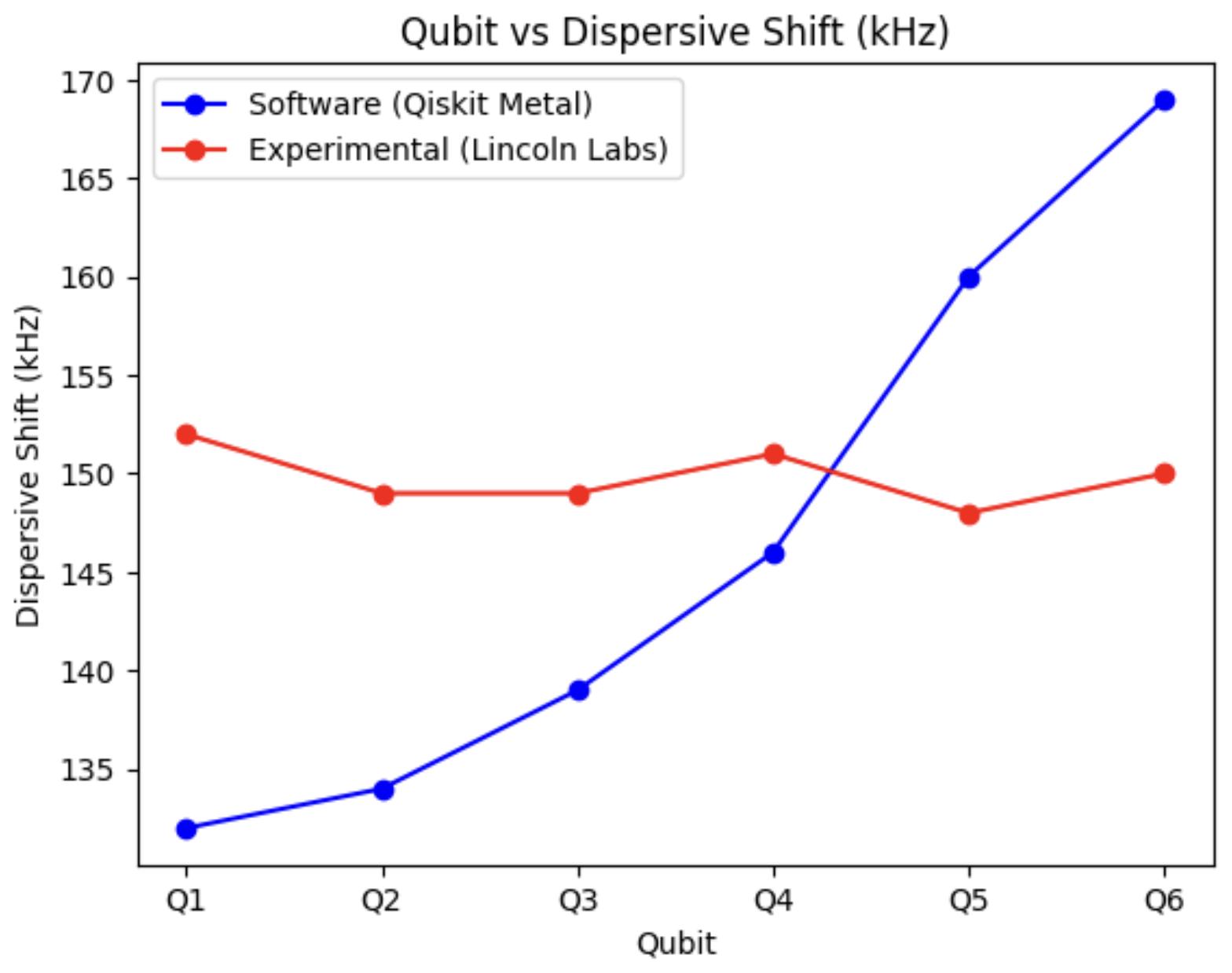
3.21Experimental(red)vsanalytical(blue)trasmonanotherimportantresultsforapre-characterizedquantumprocessorhostingsixtransmons Q1, Q2, Q3, Q4, Q5, Q6...........................58
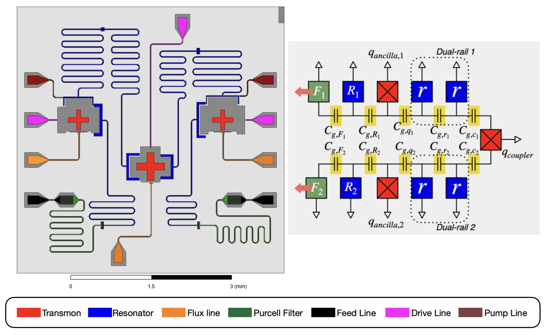
3.22Micrographofthedevice.Thefalsecolorsrepresenttheelementsof thelumpedelementmodel,asshowninthetoprightinset.Signals enterthesystemthrougheitherofthetwofeedlines(black).The Purcellfilter(green)isa � 2 standingwaveresonator,openatboth ends,andisstronglycoupledtothefeedline,withanimpedancemismatchbetweenthemactingasafilteringstep.ThisPurcellfilteris weaklycoupledtothereadoutresonator(blue),whichisinturncoupledtothequbit(red).Signalsinjectedintothefeedlinearemostly reflectedattheweaklycoupledinterfacebetweenthePurcellfilterand thereadoutresonator.Thetransmittedenergythatreachesthereadoutresonatorexcitesitsresonance,whichinteractswiththequbit. Theresultingmodulatedsignal,influencedbythequbitstate,isthen transmittedbackthroughthePurcellfilterandexitsthroughthesame feedline.Theredarrowindicatesthepathbywhichenergyleaves thefilterthroughawirebond(notshown)andenterstheexternaldetectionhardware,includingaparametricandHEMTamplifier.This S(2,1)measurementenablesthereadoutofthequbitstatebyanalyzing changesinthetransmittedsignal’samplitudeandphase........60
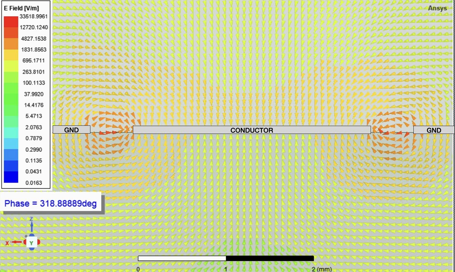
3.23Cross-sectionofaCPWresonatorshowingE-fielddistribution(V/m) ata318.8phase..............................62
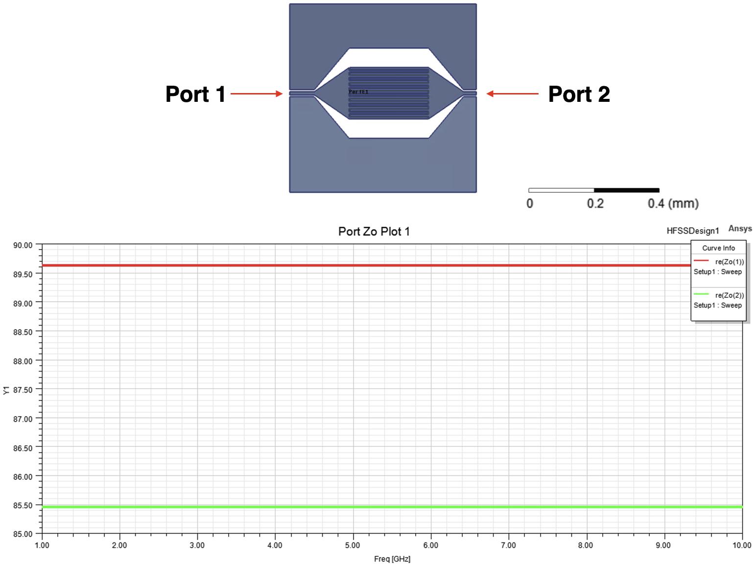
3.24DiagramoftheinterdigitalcapacitordesignbetweenthePurcellfilter andthefeedline,labeledwithPort1andPort2,alongwiththecorresponding Z0 impedanceplot.Theimpedanceplotshowstherealpart oftheimpedanceatbothportsacrossafrequencyrangeof1to10GHz. Port1exhibitsanimpedanceofapproximately89.5ohms,whilePort 2showsanimpedanceofabout85.5ohms,bothdeviatingsignificantly fromthestandard50-ohmcharacteristicimpedance.Thisintentional impedancemismatchenhancestheresonator-filtercouplingbycreating ahigh-impedanceenvironmentthatoptimizessignaltransmissionand minimizesunwantedreflectionsattheoperationalfrequencies.....63
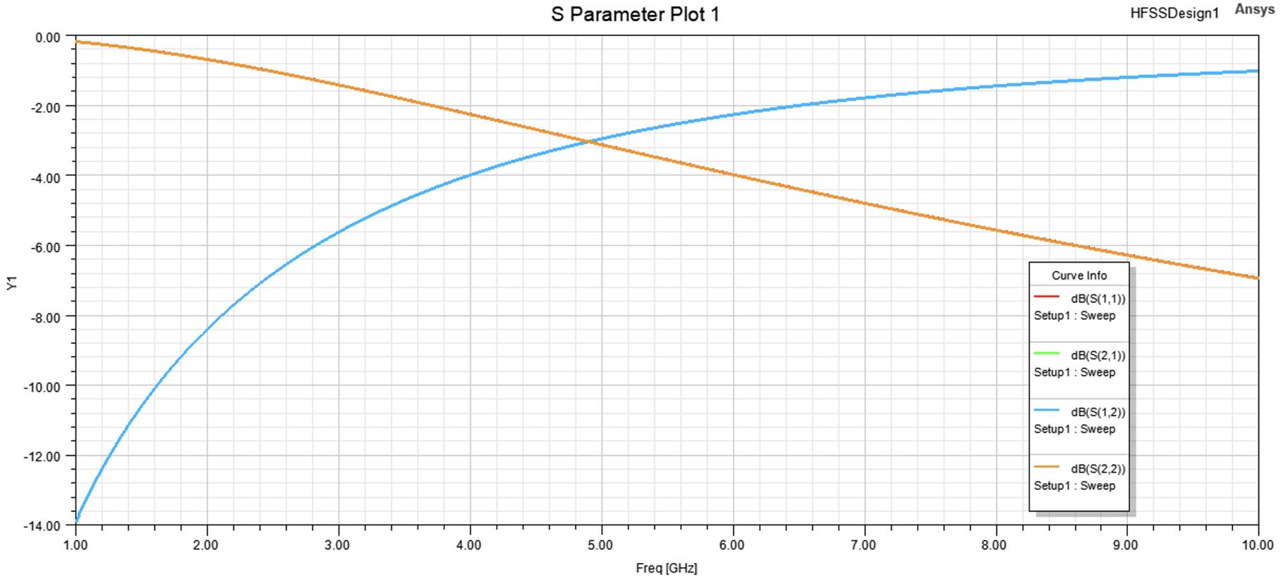
3.25S-parameterplotshowingthereflectionandtransmissioncharacteristicsoftheinterdigitalcapacitordesignintheresonator-filtercoupling system.Theplotincludesthereturnloss(S (1, 1)and S (2, 2))and transmissioncoe�cients(S (1, 2)and S (2, 1))betweenPorts1and2, demonstratingthefrequency-dependentbehaviorofthesystemand thee↵ectivenessoftheimpedancemismatchinachievingthedesired coupling...................................64
3.26Flux-tunabletransmoncomprisedoftwoJosephsonjunctioninparallel withashuntingcapacitortotheleft.Themagneticfluxisthreaded andinducedbysendingcurrentinthefluxlinetotherightofthe Josephsonjunctions.Aslotlineisaddedbetweenthefluxlineandthe flux-tunabletransmontoprotectthetransmonfrompotentialexeternal noiseresources...............................68
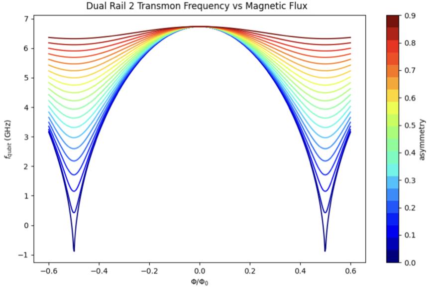
3.27Qubittransitionfrequency fqubit asafunctionofnormalizedmagnetic flux �/�0 foradual-railtransmon.ThecolorscaleindicatestheasymmetrybetweenthetwoJosephsonjunctionsintheSQUIDloop....69
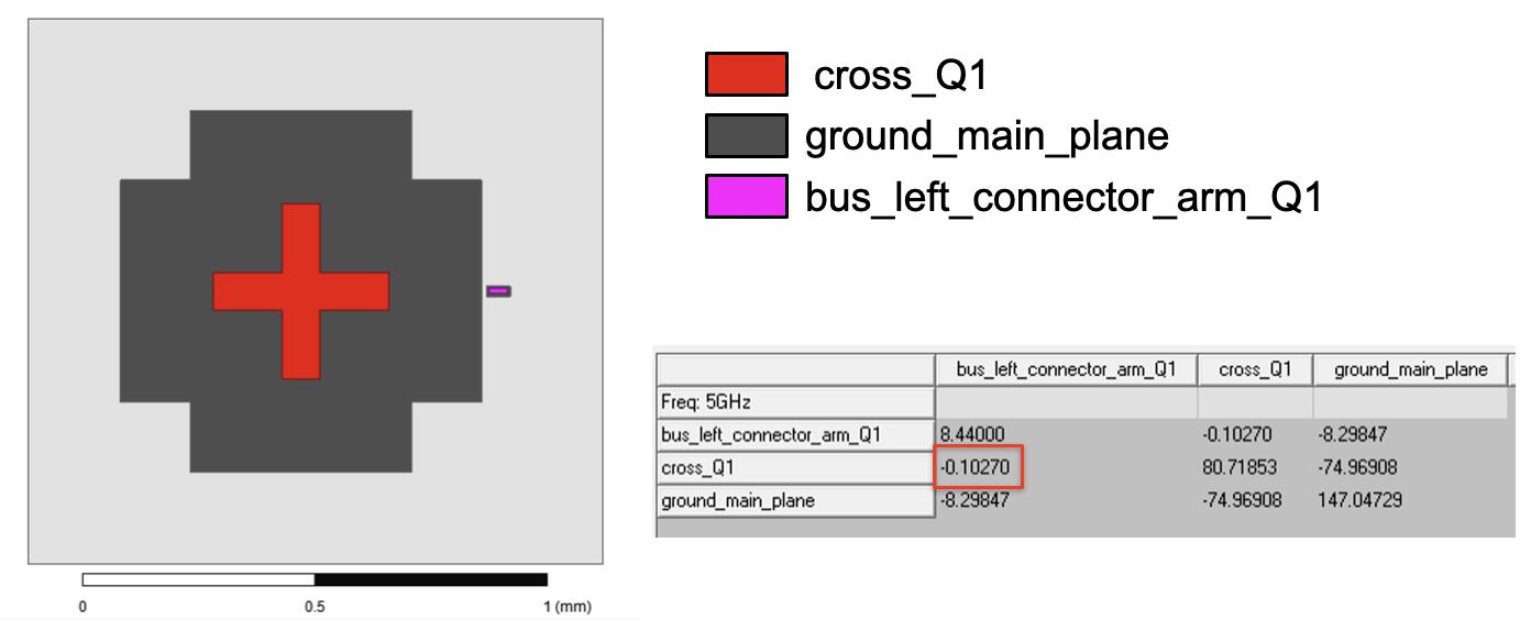
3.28Capacitancematrixbetweenthedriveline bus left connector arm Q1, thetransmon cross Q1,andground ground main plane.Thecapacitancebetweenthedrivelineandtransmon(redbox)isengineeredto be0.1fF..................................70
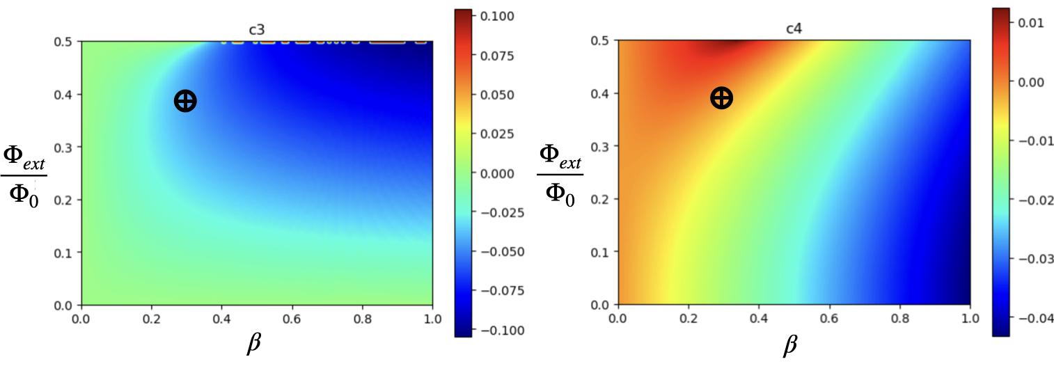
3.29Heatmapsofthecubic(c3 )andquartic(c4 )nonlinearcoe�cients,obtainedviasymbolicdi↵erentiationoftheSNAILpotential,asfunctions ofthereducedexternalflux �ext /�0 andtheratio � betweenthelarge andsmallJosephsonjunctionenergies.Theblackcrossesmarkthe chosenwhere c3 isnonzeroand c4 isclosetozero,indicatingminimal Kerrnonlinearity..............................71
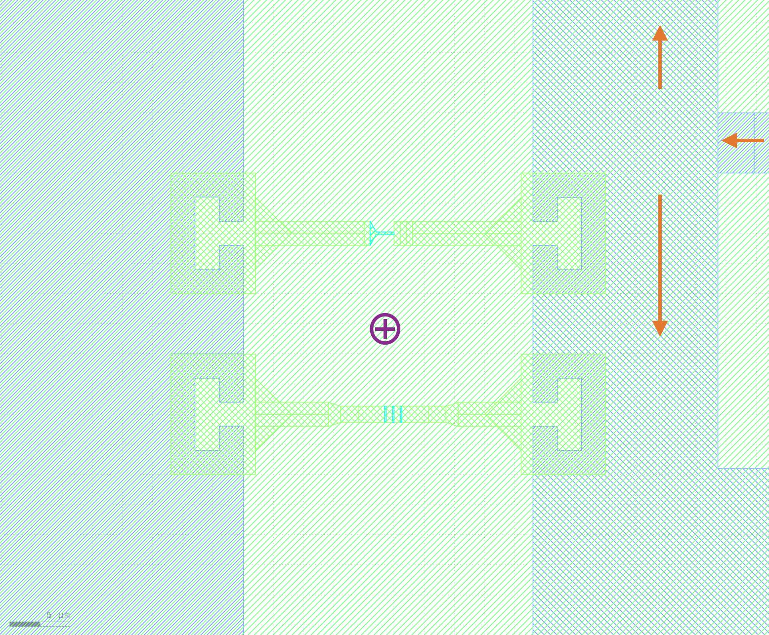
3.30Flux-tunableSNAILcomprisedofthreelargeJosephsonjunctionand asinglesmallerjunctionwithashuntingcapacitortotheleft.The magneticfluxisthreadedandinducedbyacurrentcominginfromthe
4.1Constructing |1i asa Qobj inQuTiP..................78
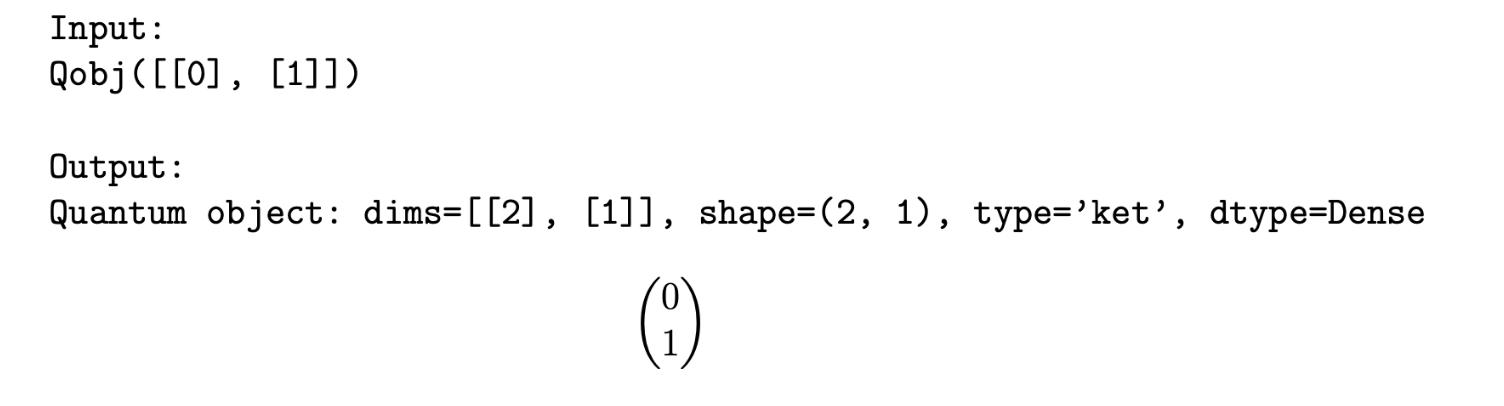
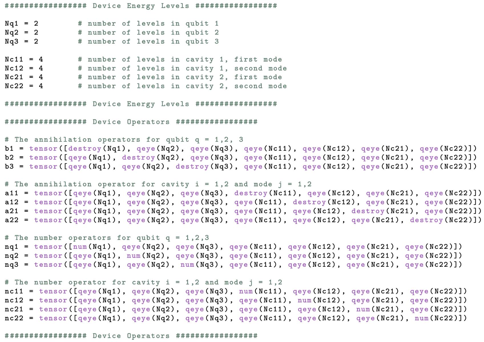
4.2LoweringandFockstateoperatorconstructions.............80
4.3LoweringandFockstateoperatorconstructions.............81
4.4Initialstatevectorconstructionwithauxiliarytransmonsintheexcited state.....................................81
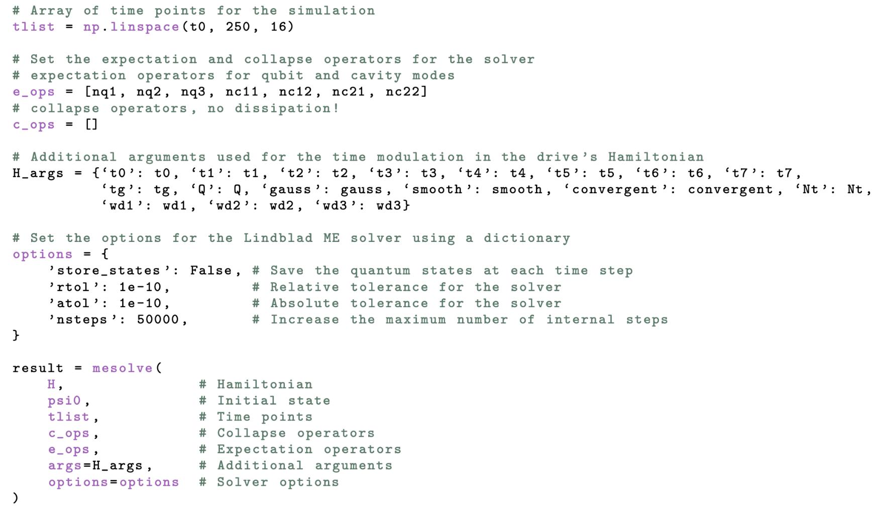
4.5Evolvesystemwith mesolve.Notethatsincethecollapseoperatorlist c ops isempty,the mesolve usestheSchrodingerequation.....82
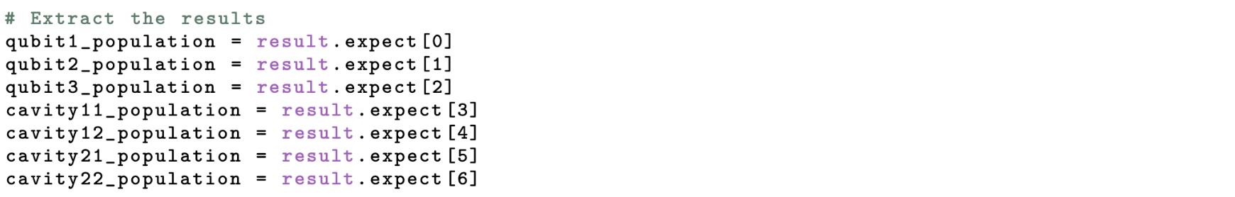
4.6Calculatingoccupationprobability....................83
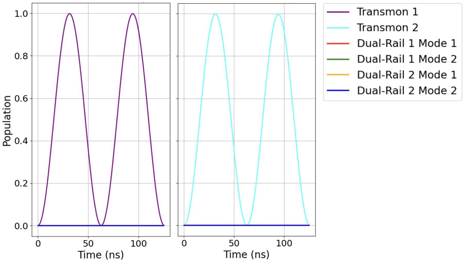
4.7Occupationprobabilityof Transmon1, Transmon2, Cavity1Mode 1, Cavity1Mode2, Cavity2Mode1,and Cavity2Mode2 with Transmon1 and Transmon2 initiallyintheexcitedstateandtherest ofthesysteminthegroundstate.....................84
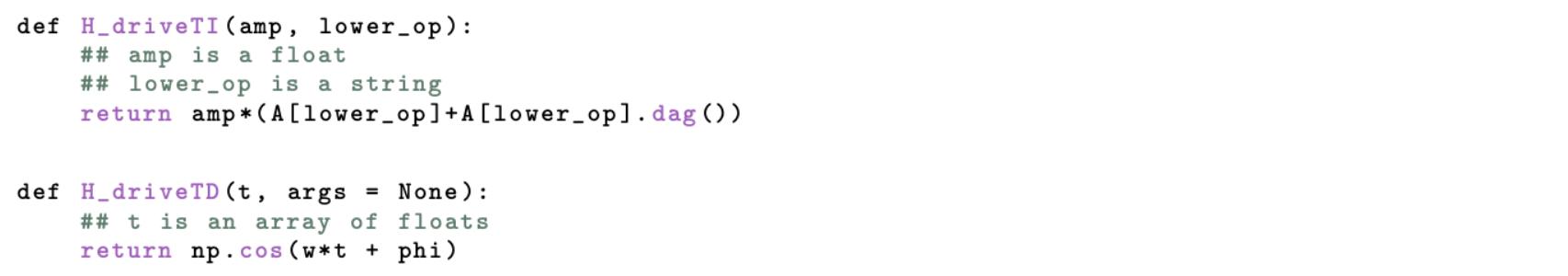
4.8 H driveTI and H driveTD functions...................85
4.9BeamsplitterinteractionsdefinitionforthedrivingHamiltonian ˆ HDrive 86
4.10 ˆ HDrive function...............................86
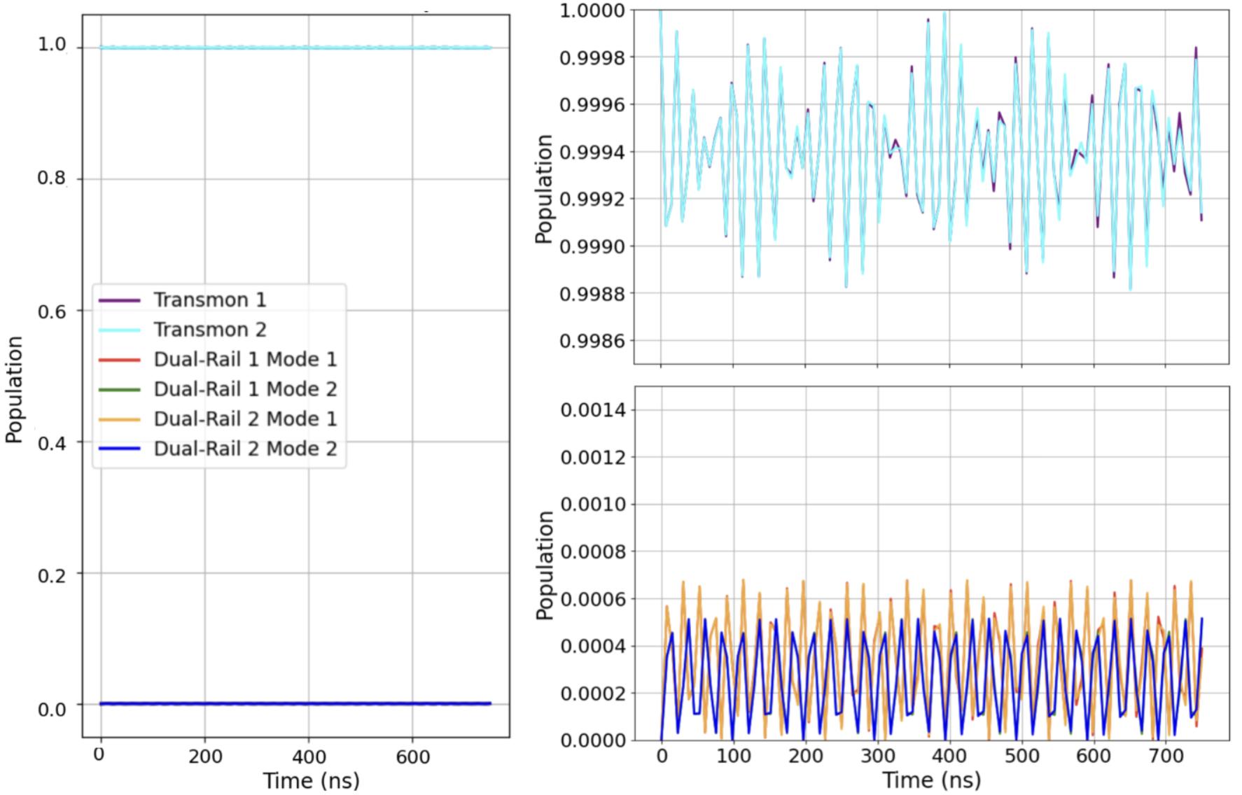
4.11Occupationprobabilityof Transmon1, Transmon2, Cavity1Mode 1, Cavity1Mode2, Cavity2Mode1,and Cavity2Mode2 with Transmon1 and Transmon2 initiallyintheexcitedstateandtherest ofthesysteminthegroundstate.....................87
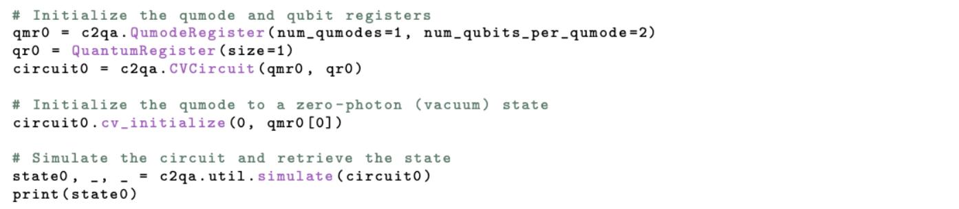
4.12BosonicQiskitcodeforgeneratingazero-photonFockstate......88
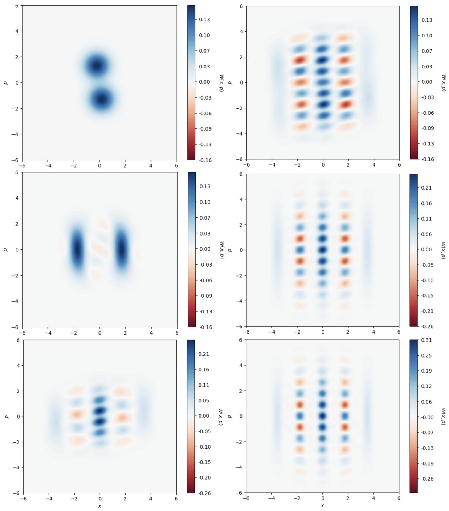
4.132Dand3DWignerfunctionrepresentationofthevacuumstatewith respecttothequadraturesoperators ˆ X andmomentum ˆ P .......90
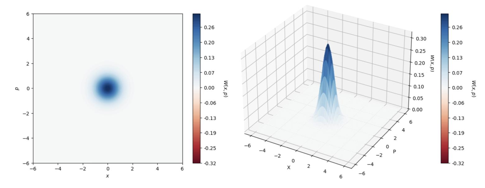
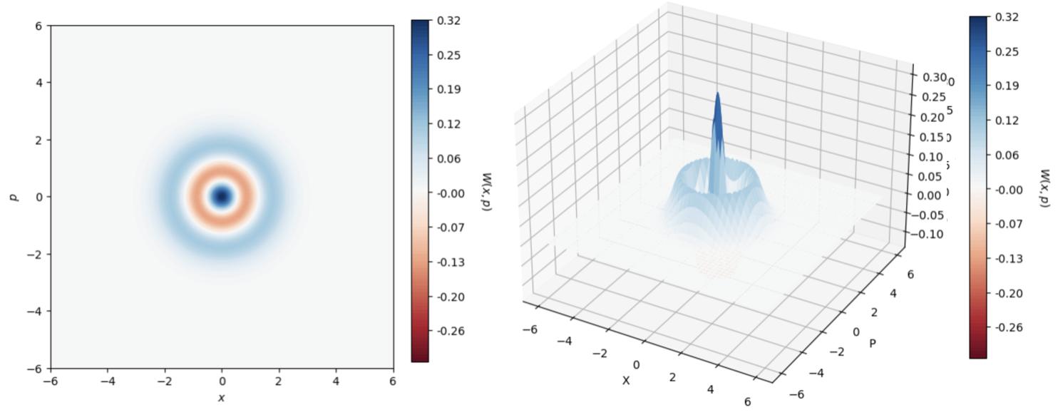
4.14Firstexcitedlevelwithrespecttothequadraturesoperators ˆ X and momentum ˆ P .Thenegativityofthedistribution,aclearproofofthe non-classicalcharacterofthestate,isevidentaroundtheorigin....91
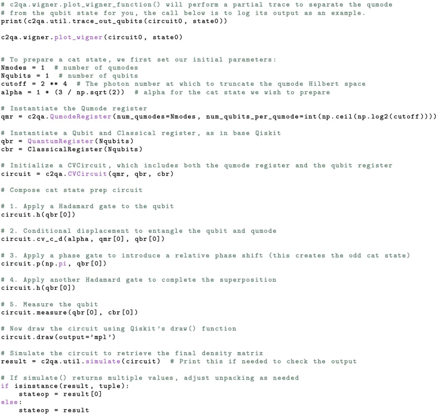
4.15BosonicQiskitcodeforgeneratinganevencatstate..........93
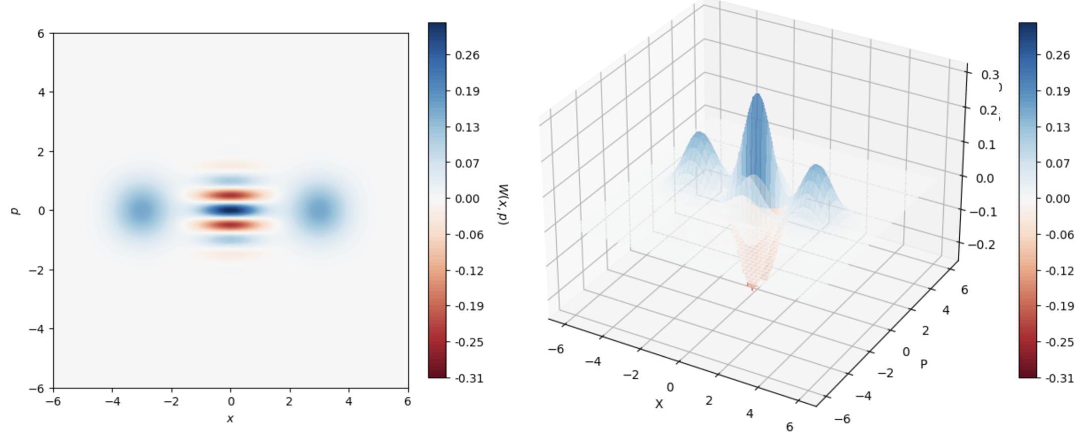
4.162Dand3DWignerfunctionrepresentationofanevencatstateinterms ofquadratures ˆ X and ˆ P ..........................94
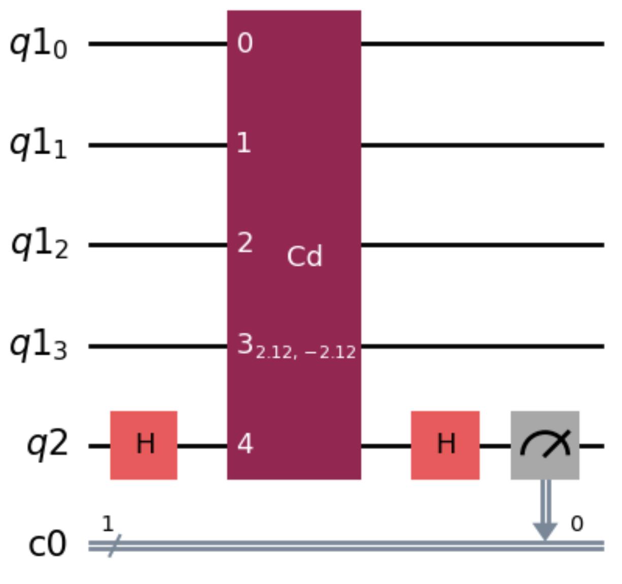
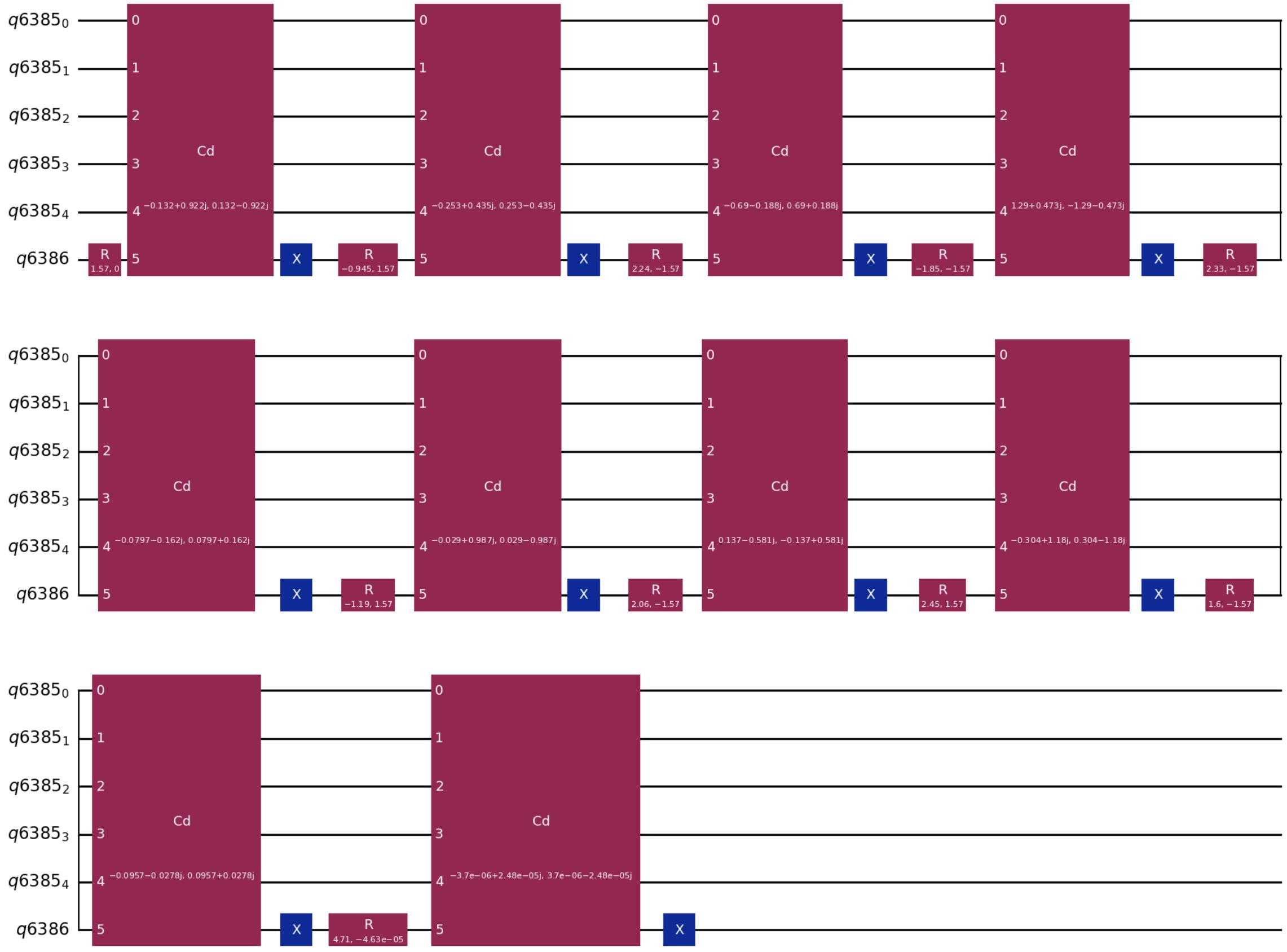
4.17Quantumcircuittocreateanevencatstateillustratingacontrolled operationonaqubit-resonatorsystemwithaqumodcuto↵ dimension of24 .....................................94
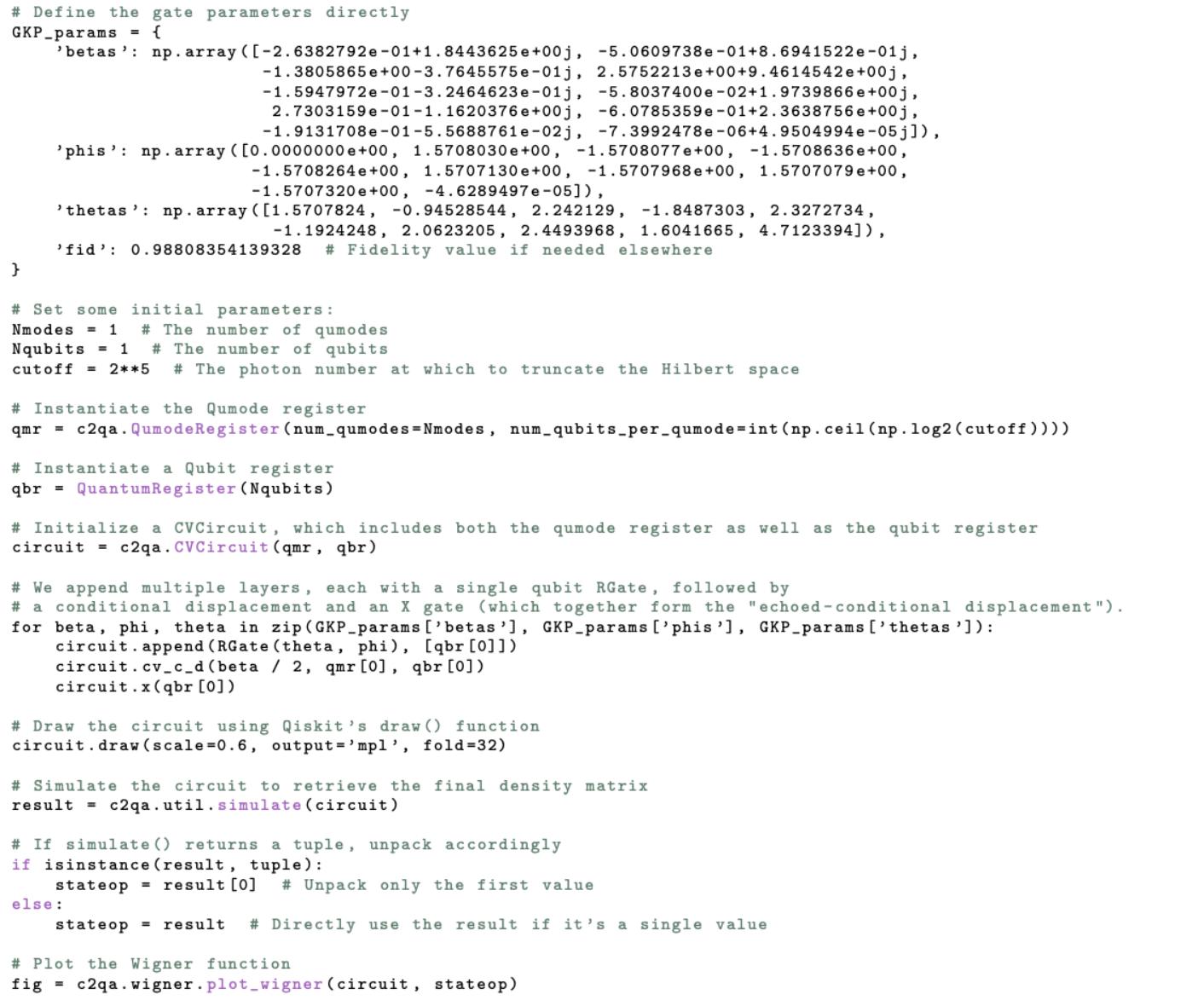
4.18BosonicQiskitcodeforgeneratingan+ZGKPcodeword.......95
4.192DWignerfunctionrepresentationofanevencatstateintermsof quadratures ˆ X and ˆ P ...........................96
4.20Quantumcircuittocreatea+ZCKPcodeworkillustratingacontrolledoperationonaqubit-resonatorsystemwithaqumodcuto↵ dimensionof24 ...............................97
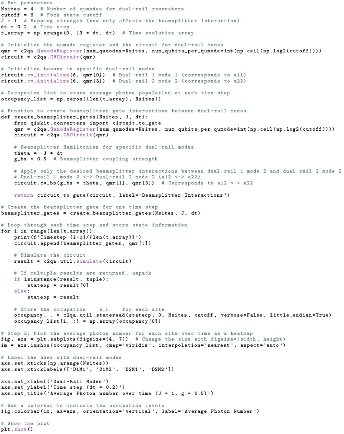
4.21BosonicQiskitcodeforgeneratingbeam-splitterinteractionbetween twodual-rails................................99
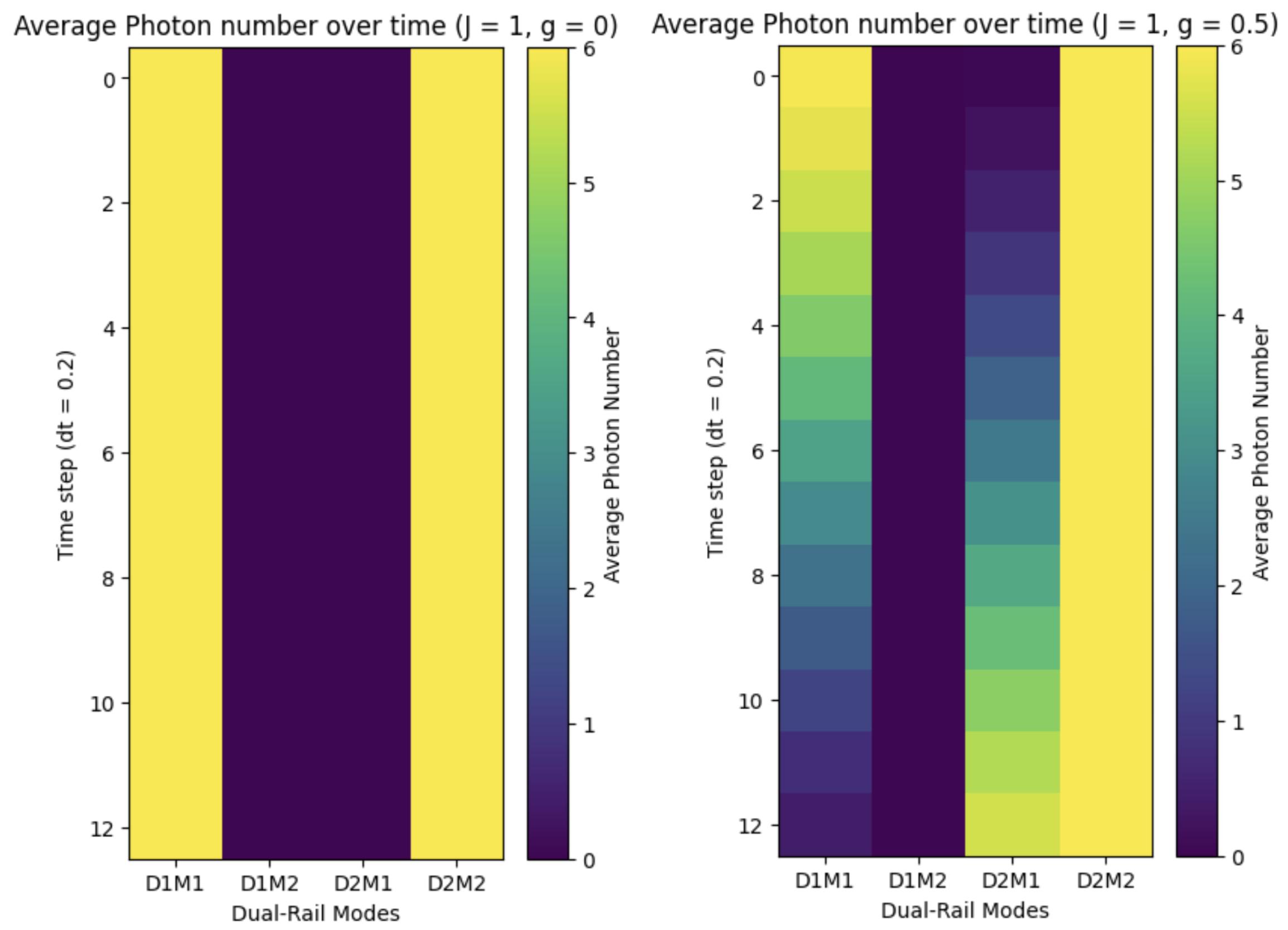
4.22Simulationofbeam-splitterinteractionbetweenfourqumodeswith hoppingrateJandbeam-splitterinteractionstrengthU.Weinitialize thesystemsuchthat Dual-Rail1Mode1 and Dual-Rail2Mode
2 have6photonseach,and Dual-Rail1Mode2 and Dual-Rail2 Mode1 arevacant.Theaveragephotonnumberasafunctionoftime forvariousJ/Uisshownwhenthemicrowavepumpisdrivenatthe detuningbetween Dual-Rail1Mode1 and Dual-Rail2Mode1..100
ListofAcronyms EC ChargingEnergy
EJ JosephsonEnergy
T1 DepolarizationTime
T2 DephasingTime
UUnitaryOperator
ˆ
a(t)Cavity(Creation)AnnihilationOperator
ˆ
b(t)Qubit(Creation)AnnihilationOperator
�ij Di↵erenceFrequency, !i !j
ed DriveStrength
✏p ProbeStrength
�i i-componentPauliMatrix
�+ PauliCreationOperator
� PauliAnnihilationOperator
⌃ij SumFrequency, !i + !j
� Gauge-InvariantPhaseDi↵erence
ˆ
� Gauge-InvariantPhaseDi↵erenceOperator
� DispersiveShift
| i QuantumState
LJ JosephsonInductance
!q qubitresonantfrequency
↵ qubitanharmonicity
!r CPWresonatorresonantfrequency
1 Motivation Wetypicallythinkofquantumcomputersassystemsengineeredtostoreandmanipulatequantuminformationusinganensembleofqubits,whichmaybephysically implementedwithsuperconductingcircuits,trappedions,photonics,orothertechnologies.However,thedecisiontousequbits—two-levelquantumsystems—asthe baseunitofinformationisnottheonlychoice,norisitnecessarilythemoste�cient one.Forquantumerrorcorrectionandquantumsimulation,itismoreproductiveto considerothermethodsinwhichthebasicunitsincludemorethantwolevels.
Onepromisingavenueistheuseofhardwaresupportingbosonicmodes,eitherin concertwithqubits—inhybridqubit-bosonicsystems—orasanalternativetothe useofqubitsentirely,asincontinuous-variablequantumcomputing.Abosonicmode islikeaquantumharmonicoscillatorand,inthecontextofquantumcomputing,is generallyreferredtoasa“qumode.”Theideaistoencodealogicalqubitinthevast Hilbertspaceofabosonicmodeandemploythe“extraspace”forerror-correction. Therearemanyoptionsforhowtoembedalogicalqubitinabosonicmode,e.g., thecatcode[1][2],binomialcode[3][4],andGKPcode[5][6][7].Allthreeofthese codeshaveexperimentallyreachedorexceeded“break-even,”(i.e.,thelifetimeofthe logicalqubitexceedsthatofallbasecomponentsinthesystem),afeatyettobe achievedinqubit-basederrorcorrection.
Theworkofthisthesisexploresqumodesasthefundamentalbaseunitofinformationmotivatedbythe quantumlight-switchexperiment,whichisintroducedinthe followingsection.
Figure1.1:Adaptedfrom[8].Designsofsuperconductingresonatorsandtheirlifetimes.(a)IllustrationsoftwopopularresonatordesignsinbosoniccQED,with indicationsoftheirapproximatesizesandelectricfielddirection.(b)Aselectedcollectionofresonator T1 lifetimesforthetwoillustratedresonatordesignsextracted fromtheliterature.Thelifetimesofresonatorshavebeensteadilyincreasingover thelast15yearsduetotheengineeringofmaterialsandgeometries.Theshapeof thepointsindicatesthesuperconductingmaterial,andthecolorcorrespondstothe adjacentdiagrams.Wehighlightstudiesthatsuccessfullyintegrateoneormorenonlinearcircuitswithablackborder.References:CPW:[9,10,11,12,13,14,15],3D � 4 coaxialcavity:[16,17,18,19,20]
1.1 Thequantumlight-switchexperiment ThephotoninteractionexperimentbetweentwoqumodesfromBenjaminJ.Chapmanetal.[21]aimedtocontrolphotonhoppingbetweentwobosonicsystemswith minimalphotonstatedegradation.Inthisexperiment,quantuminformationisencodedinthemultiplediscreteenergylevelsoflightwithinahighlycoherent3D � 4 coaxialresonator,duetoitsabilitytoachievelifetimesof104 µs(seeFig.1.1).Its lifetimeisamongthelongestrecordedforanybosonicsystem,secondonlytoanother 3Dbosonicsystemknownasthe3DShrooms(notpicturedinFig.1.1).Next,they coupledatransmontoeachofthe3D � 4 coaxialoscillatorindependentlytoprepare quantumstatesthatinvolvequbit-resonatorsystem.Thequbit-resonatorsystemis
complementedbyresonator-resonatorsystemstomeettherequirementsforuniversal controlofthequantumharmonicoscillatorknownas non-Gaussiansingle-moderesources andand Gaussiantwo-moderesources.Non-Gaussiansingle-moderesources refertoquantumstatesthatexhibitnon-Gaussianbehaviorinphasespace,such asphoton-addedorcatstates,andGaussiantwo-moderesourcesrefertoentangled statesbetweentwomodes,liketwo-modesqueezedstates.Thisapproachmirrors paradigmsinlinearoptics,whereuniversalcontrolofcontinuous-variablesystems isachievedwithGaussiantwo-modeinteractionsandanon-Gaussiansingle-mode resource[22,23].Unlikefullylinearopticsystems,thebigadvantagesofusingtransmonqubitand3D � 4 coaxialoscillatoristhestrongcouplingthatcanbeinduced betweenthetwo,allowingforfastercreationandmanipulationofquantumstates. Thestudyoftheseinteractionsinsideabosonicsystemisknownasbosoniccircuit quantumelectrodynamics.
IfwenowfocusedontheGaussiantwo-moderesources,whenphotonspassesfrom one3D � 4 coaxialresonatortoanotherthroughatransmoncoupler,theperformance hasbeenlimitedbythespeedandfidelityoftheengineeredbeam-splitterinteraction [24].Typically,spuriousHamiltonianinteractionsandadditionalerrorchannelsfrom thetransmoncouplerelementisthesourceofthisdistortionofthephotons.Inthis experiment,theteamsuccessfullysuppressedthesespuriousHamiltonianinteractions withoutintroducingunwantedinteractionsbetweenthetwo3D � 4 coaxialresonator usingatunablecouplerbasedonasuperconductingnonlinearasymmetricinductive element(SNAIL)dipoleelement.Theengineeredcouplerrapidlytransferphotons fromonecavitytoanotherwithoutdegradingthephotons’quantumstate.This experimentalresultgivesinsightintothecrucialsteptowardsfastandhigh-quality quantumgatesforquantumcomputersbasedonbosonicsystems.In2024,their advancementshavesignificantlyinfluencedthefieldsofquantumerrorcorrection[25, 26,27,28],quantumoptics[29,30,31],quantuminstrumentation[32,33,34],and
1.2 Theexperimentonthechip Thisthesisispartofalargerprojectaimedatdemonstratingtheinteractionbetween qumodesusingaSNAILdipoleelementonafullyplanarsolid-statechip.Instead ofencodingthequbitina3D � 4 coaxialoscillator,wereplicatetheinteractionusing 2D � 2 CPWresonators.Inoursetup,thenon-Gaussiansingle-moderesourcesare replicatedbycouplingatransmontoaCPWresonator.Remarkably,thetransmon isvisibletothenakedeyeandiscomposedofbillionsofatoms,yetithasaquantized setofenergylevels.TheGaussiantwo-moderesourcesarereplicatedbycouplingtwo CPWresonatorsthroughaSNAILdipoleelement.Toextendthenumberofenergy levelsofthebosonicsystemcoupledtothetransmon,wereplacedeachindividual CPWresonatorwithapairofCPWresonators,collectivelyknownas dual-rails. Ultimately,theplanarsolid-statechipcanbedescribedastheinteractionbetween twoplanardual-railsusingaSNAILdipoleelementwithnon-Gaussiansingle-mode andGaussiantwo-moderesources.
ThemajoradvantageofcircuitQEDoverotherapproaches,suchascavityQED, isthatthepropertiesofallcircuitelementscanbeengineered[37].IncavityQED, wearelimitedbythenaturalpropertiesofatoms,whereasincircuitQED,wecan designandadjusttheshapes,parameters,andcharacteristicsofourcomponents, withpotentialsetupsallowingfor insitu flux-dependenttuning.Thisflexibility isconstrainedonlybyourfabricationtechniquesandcreativity.Additionally,the largesizeofthetransmonenablesmuchstrongercouplingbetweentransmonand resonatorsbecausethetransmon’se↵ectivedipolemomentcanbeordersofmagnitudelargerthanthoseofalkaliandRydbergatomstypicallyusedincavityQED [38].Inthesenewlyemergedparameterregimes,thecouplingstrengthssurpassthe
decayrates,allowingforstrongcoherentinteractions[39].Theseregimeshaveenabledexperimentaltestingofphenomenainquantumopticsthatwerepreviouslyonly theoreticallypredicted[40].Finally,thequantumdynamicsonourmacroscopicchip canbeconvenientlycontrolledwithclassicalmicrowavelightfieldssources,suchas theUltra-FastQuantumControlHardwareOPX+fromQuantumMachines[41]and QuantumInstrumentationControlKit(QICK[42]).
Anotherimportantdi↵erencebetweencavityQEDandcircuitQEDisthatin circuitQED,thetransmonandCPWresonatorsarebothfixedinplace.Onthechip, weplacethetransmonandtheCPWresonatorsclosetoeachother,butweengineer themtohaveverydi↵erentresonantfrequencies.Whenthechipisnotdriven,thereis littletonoenergyexchangebetweenthetransmonsandtheCPWresonatorsbecause excitingtheresonantofonecomponentrequiresadi↵erentamountofenergythan excitingtheother.Nevertheless,thestatesofthetransmonsandCPWresonators canbeinferredfromthefrequencyshiftcausedbythecapacitiveloadingtheyexert oneachotherknownasdispersiveshift.
Theenergyexchangebetweenqumodesofthepairofdual-railsrequiredforthe Gaussiantwo-moderesourcescanbeachievedbystronglycouplingthedual-railsto aflux-dependentSNAILdipoleelement,whichisalsostronglycoupledtomicrowave drive/pump.Whenthedrivefrequencyofthemicrowavepumpdrivematchesthe energydi↵erencebetweentwoqumodesofeachdual-rail,photonswillstarthopping betweenthesetwobosonicsystems.Ontheotherhand,theenergyexchangebetweenthetransmonandtheCPWresonatorsrequiredfortheGaussiansingle-mode resourcescanbeachievingusingindependentweaklycoupleddrivestothetransmon andCPWresonators.
1.3 Applicationsofsuperconductingquantumcircuits CircuitQEDleveragesquantumphenomenasuchassuperpositionandentanglement toexponentiallyexpandthecomputationalspace,enablingmassiveparalleloperations[43].ThismakescircuitQEDoneoftheleadingarchitecturesforbuildingscalablequantumcomputerswithmanyqubits.In1982,RichardFeynmanproposedthe ideaofsimulatingonequantumsystemwithanother[44],highlightingthepotential ofquantumcomputingtotacklecomplexproblemsthatclassicalcomputersstruggle with,suchasmedicinaldrugdiscoveryandhigh-temperaturesuperconductivity[33].
Today,quantumsimulationsareappliedtovariousfields,includingcondensedmatterphysics,smallmolecularsystems[45,46],andchemicalprocesses[47].A remarkableexampleofquantumcomputing’spotentialwasdemonstratedinapaper publishedbyGoogleQuantumAI,claimingtohaveachievedquantumsupremacy [48].Theirtransmon-basedquantumcomputersuccessfullysampledtheoutputofa pseudo-randomquantumcircuitin200seconds—ataskestimatedtotakeastate-ofthe-artsupercomputer2.5days.
Despitetheseadvancements,theboundariesbetweenquantumandclassicalcomputationalcapabilitiescontinuetoevolve.AstrikingdevelopmentcamefromEwin Tangshowedthataclassicalalgorithmcouldsolvethe“recommendationproblem”— ataskpreviouslybelievedtobenefitfromquantumspeedup—justase�cientlyas aquantumalgorithm[49].Thisdiscoverychallengedthenotionofquantumadvantageinthisarea,demonstratingthatclassicalcomputerscansometimesreplicatethe e�cienciesofquantumalgorithms.
Tang’sworkunderscoresthedynamicinterplaybetweenquantumandclassical computing,revealingthatbothhaveuntappedpotentialandencouragingcontinued explorationinbothdomains.Asquantumcomputingadvances,itremainscrucial
toidentifyareaswherethecomputationalcomplexitiesofquantumcomputingtruly excelsoverclassicalmethods,buildingadeeperunderstandingofeachapproach’s capabilitiesandlimitations.
1.4 Structureofthethesis ThisthesiswillbeginbydiscussingthetheoreticalaspectsofcircuitQEDinChapter 2,layingthegroundworkforourmathematicalandphysicalunderstandingofthe variouselementsandinteractionsonthechip.Chapter3willpresentthemethods usedtodesignandanalyzeafullyplanardual-railquantumprocessor.Chapter4 willdescribethetechniquesemployedtosimulatenon-drivenanddrivenevolutionof thetransmonalongwithhigh-levelbosonicstatesimulations.Finally,Chapter5will presenttheconclusionsofthiswork,alongwithrecommendationsforfutureresearch.
2 Theoryofcircuitquantumelectrodynamics Figure2.1:IllustrationofaJosephsonjunction.(a)Cross-sectionalviewshowing quantumtunnelingacrosstheinsulatingbarrier(oxidebarrier)sandwichedbytwo electrodes.(b)Topviewofashadow-evaporatedDolanBridgeJosephsonjunctionin betweentwoaluminumlayers(greyandred).Thequantumtunnelingoccursinthe narrow,finger-stylestructure,showninthezoomed-inarea.
2.1 Thetransmonqubit Wehavechosenthetransmonastheauxiliaryqubitthatcouplestothedual-rails. ThetransmoncanbemodeledasaquantumLC-oscillatorwherethelinearinductor L isreplacedbyanonlinearinductor.Incomparisonwithothersuperconducting-based qubits,thetransmonisparticularlynotableforitsreducedsensitivitytochargenoise. Thissectionwillbeginbydiscussingthekeycomponentofthetransmonqubit—the Josephsonjunction—andexplorevarioususefultransmonmodels.
2.1.1 TheJosephsonJunction WestartourconstructionofthequbitwiththeJosephsonjunction.Thejunctionis fabricatedbytwosuperconductingelectrodesseparatedbyathininsulatingbarrier [50]asillustratedinFig.2.1.Inthesuperconductingstate,electronswithopposite spinarepairedupintoCooperpairs.Becauseoftheinsulatingbarrier,thesepairs cannotelectricallytunnelacrossthejunction,givingrisetoaphasedi↵erence ' in themacroscopicwavefunctionacrossthebarrier.
Ifwediveintothemathematicaldescriptionofthisphenomenon,inthepresence ofapotentialdi↵erence V acrossthejunction,thephaseevolvesas
[51]wherethefactor2comesfromthefactthatweconsiderpairedelectrons.The Josephsone↵ecttellsusthatthecurrentthroughandthevoltageoverthejunction arerelatedtothephasedi↵erence ' as
where I0 isthemaximumcurrentthatcanflowthroughthejunctiontheso-called ascritical-currentparameterand �0 = h/2e isthemagneticfluxquantum.Wegain moreinsightfromthesetwoexpressionsbytakingthetimederivativeof IJ andthe substitutionof V .Thisyieldsthedi↵erentialequationgivenby
whereweknowtheinductanceisdefinedbytherelationship:
ThisleadstotheconclusionthattheJosephsonjunctionbehavesasanon-linear inductorwithaJosephsoninductancegivenby
where ' rangesfrom ⇡ to ⇡ duetotheperiodicityof2⇡ periodicityinherentin thesuperconductingphasefromthetwosuperconductingelectrodes.Incontrastto linearinductors,wheretheenergyisstoredinamagneticfieldcreatedbytheflowof current,intheJosephsonjunction,itisstoredinphase-dependentsupercurrentsof
Cooperpairs;therefore,behavingasakineticinductor.
TheCooperpairwavefunctiondecaysexponentiallyfromboundariestothemiddle oftheinsulatingbarrier.Thatis,theprobabilityoffindingaCooperpairinthe middleofthebarrierisaminimumandattheedgesitisamaximum.WhenCooper pairstunnelacrossthejunctiontheirmomentuminthemiddleofthebarriershould bemoreattheedges.Thismomentumisiswhattheenergyisstoredin.Thetotal energystoredinthejunctionisgivenby
where
isknownastheJosephsonenergy.TheJosephsonenergyquantifiestheenergyassociatedwithaCooperpairtunnelingacrossthejunction.
2.1.2 TheCooperPairBox ToprovidetheJosephsonjunctionwithasinkandasourceofCooperpairs,wecan connectitwithtwosuperconductingislandsinseriestoacapacitor.ThisconfigurationisknownastheCooperpairbox(CPB)asillustratedinFig2.2.
TheCPBischaracterizedbytwokeyenergyscales[37],[52].Ononehand, thereistheenergy EJ storedinthejunctionasacurrentpassesthrough.Onthe otherhand,thereisthechargingenergy EC = e2 /(2C⌃ )ofasingleelectrononthe capacitance,whichis,inotherwords,theenergyrequiredtoaddasingleelectron tothecapacitance[53].Here,thetotalcapacitance C⌃ = Cg + CJ oftheCPBto groundisthesumofthegatecapacitance Cg andthee↵ectivecapacitance CJ of theJosephsonjunction’spairofelectrodes.TheHamiltonianoperatordescribingthe totalenergyoftheCPBisneatlyderivedin[43]usingcircuitquantization.Itisgiven by
Figure2.2:SchematiccircuitrepresentationofaCooperpairbox.Theislandis separatedfromtherestofthecircuitbyacapacitor Cg andtheJosephsonbarrier.
Inthisexpression,ˆ n isthediscretenumberoperatorofCooperpairsthathave tunneledthroughthejunction,andˆ ' istheoperatorofthephasedi↵erence ' across thejunctionexploredinSection2.1.1.Thegatecharge ng =(Qr + Cg Vg )/2e can fluctuateduetoenvironmentalinfluences[54,55]andisdefinedbythevoltage Vg atthegateandtheo↵setcharge Qr .Thefactorof4infrontof EC arisesbecause theCoulombenergyrequiredtochargeaCooperpairisfourtimeslargerthanfora singleelectron[55].TheenergylevelsoftheCPBcanbedividedintotwocategories [56]:(1)thoseconfinedbytheJosephsonpotential,and(2)higherunconfinedstates typicallyconsiderednegligible,exceptunderstrongdrivingconditionsasshownin rightpictureinFig.2.3(b).
WecanvisualizetheCPBasaquantumrotorinagravitationalfield[54]and showninFig.2.3(a).Imagineamassconnectedtoamasslessrod,rotatingarounda frictionlesspivot.Therotor’spositionisdeterminedbytheangle ',andthenumber operatorˆ n isanalogoustoitsangularmomentum.Thechargingenergy EC represents themomentofinertia,whiletheJosephsonenergy EJ isthetorqueproducedby gravitationalforce.Tounderstand ng ,wecanimaginethequantumrotorcarryinga
chargeandbeinginthepresenceofauniformmagneticfield,perdiculartotheplane ofmotion.Thee↵ectoftheo↵setcharge ng canbeinterpretedasthethee↵ectof theangularmomentumofthechargedmassduetotheforceoftheexternalmagnetic field.
Figure2.3:Adaptedfrom[54].TheCooperpairboxisanalogoustoacharged, sti↵-rodquantumrotorinaconstantmagneticfieldrepresentedby ng .Therotor’s positionisdeterminedbythephase ',anditsangularmomentumisdescribedbythe discreteoperatorˆ n
ChargeBasisRepresentation TheCPBregimeisdefinedbythecondition EC � EJ ,sothecapacitivecharging oftheislandisthedominantenergyscaleintheCPB.Inthisregime,knownasthe chargequbit,itisnaturaltoexpressdynamicsintheeigenbasis |ni oftheCooper pairnumberoperatorˆ n,labeledbytheexcessnumber n ofCooperpairsontheisland [52].Thenumberoperatorˆ n isdefinedas
wherethesumrunsfrom �1 to+1 foraninfinitenumberofCooperpairs.
Whenthenumberoperatorˆ n actsontheeigenstate |ni,ityieldstheeigenvalue n,whichcorrespondstothenumberofCooperpairsinthatstate.Mathematically, thiscanbeexpressedas:
whereˆ n ise↵ectivelytheoperatorthatmeasurestheexcessnumberofCooper pairsontheisland.
Similarly,thephaseoperatorisgivenbythecanonicalcommutationrelation [ˆn,ei' ]= ei' ,resultingin
functioningasaladderoperatorforthechargestates.Expressingthecosinefrom Eq.(2.8)inexponentialformallowsustowritetheCPBHamiltonianinthecharge basisas
2.1.3 TheTransmonRegime Forpracticalapplications,thequbitwewanttoengineermustbesu�cientlyanharmonicandstable.IfweexaminetheCPB’senergylevelsinthe EC � EJ regime reveals,itrevealsthattheenergyrequiredtoexcitetheCPBishighlydependenton theo↵setcharge ng asshowninFig.2.4,makinghighlysusceptibletoenvironment influences.Havingtheabilitytopreciselycontrolthegatechargewouldallowfor stabletransitionenergiesbetweentheCPB’senergylevels.However,inpractice, fluctuationsfromenvironmentalelectrons,quantumfluctuations,andinstrumental imperfectionsinducevariationsin ng ,a↵ectingtransitionfrequenciesandcausing chargedispersion,whichcanobscureCPB’sphaseinformation.
Onestrategytomitigatethisdispersioninvolvesbiasingthegatevoltagetothe CPB’schargedegeneracypoint,knownasthesweetspot,wheretransitionfrequency derivativesarezero,asshowninthedashedlinesinthetopleftinsetinFig.2.4. Anotherapproach,proposedbyKochetal[54],involvesshuntingthejunctionwitha largecapacitance CB ,minimizing EC andelevating EJ asthedominantenergy.This reduceschargesensitivity,andinthetransmonregime EJ � EC ,theCPBbecomes relativelyinsensitivetogatechargenoise,withany ng consideredasweetspot,as showninthelowerrightinsetinFig.2.4.
Anharmonicity Oneoftherequirementstoinducethenon-Gaussiansingleresourcesdiscussedin theMotivationsectionisthequbit-resonatorsystem.Inthissystem,wewantthe transmontobesu�cientlyanharmonictoe↵ectivelyworkasatwo-levelsystem. Aharmonicoscillator,withequidistantenergylevels,isunsuitablebecauseapulse atthetransitionfrequencymightexcitehigherstates(seeFig.2.5).Denotingthe
Figure2.4:Adaptedfrom[54].Thisfigureillustratestheenergylevelsfordi↵erent ratiosof EJ /EC .Increasingthisratio,achievedbyshuntingtheCooperpairbox withalargecapacitance,reducesthestrongdependenceongatebias ng andthus minimizessensitivitytochargenoise.Thearrowsin(a)indicatethesweetspot.The regimedepictedin(d),where EJ � EC ,isknownasthetransmonregime.
groundstateas |g i,thefirstexcitedstateas |ei,andthesecondas |f i,werequire thetransitionfrequency !ge tobedistinctfrom !ef ,definingtheanharmonicityas
↵ = !ge !ef
TwoprimarysourcesofanharmonicityexistfortheCPB[57]:increasedquantum fluctuationsathigherexcitations,characterizedbyzero-pointphasefluctuationsgiven by
wherethefluxladderoperatorisgivenby ˆ � = �ZPF ( ˆ b + ˆ b† ).Here, ˆ b and ˆ b† arethe ladder(annihilationandcreation,respectively)operatorsofthequbitexcitations.In
Figure2.5:Comparisonoftheenergylevelspacingbetweenaharmonicoscillatorand atransmonqubit.Theharmonicoscillator’squadraticpotentialresultsinequidistant energylevels,allseparatedbythesameenergy,whichmakesitunsuitableforuse asaqubit.Incontrast,thetransmonqubit,withitscosinepotential,hasvarying transitionenergiesbetweensubsequentenergylevels.Thisvariationallowsforprecise controloverindividualtransitionsbetweentransmonstates.
theextentofEq.(2.13),wefindforhigherexcitationsthat
Theseconde↵ectcontributingtotheanharmonicityisthenon-lineardependence onthephase ' duetothecosineinEq.2.8.Together,thesee↵ectsresultinnondegeneratetransitionfrequenciesbetweenhigherexcitedstates.
WhiletheCPB’sregimeo↵erslargeanharmonicity,itissensitivetogatecharge fluctuations.Thetransmon,conversely,isnot,thoughitsanharmonicitydecreases withincreased EJ /EC ratio.Fortunately,thenoisesensitivitydecreasesexponentiallywhileanharmonicitydeclinesonlyalgebraically,maintainingfunctionalityin thetransmonregime[54].
Returningtotherotoranalogy,high EJ /EC impliesstronggravitationalpull, keepingtherotornearperpendiculartotheground ' =0.Theanharmonicityisa minorperturbationontheharmonicbehavior[54,43,57,58],allowingustotruncate theTaylorexpansionof EJ cosˆ ' atthefourthorder:
ThisdescribesthetransmonasaDu�ngoscillator.
2.1.4 CouplingtoaCavity ThebosonicsystemwehavechoseninthisthesisworkistheCPWresonator.This quasi-one-dimensionaltransmissionlinefeaturesanarrowcenterconductorflankedby groundplanesandsupportsstandingwaveresonancesdeterminedbyitslengthand geometry.Eachmode j oftheresonatorcanbemodeledasaparallelLCresonator, describedbytheHamiltonian
whereˆ a(†) j istheannihilation(creation)operatorformode j atfrequency !j , satisfying[ˆ aj , ˆ a† j 0 ]= �j,j 0 [59].
Addingaphotonofmode j increasestheenergyby ~!j ,makingtheCPWresonatoraharmonicoscillator.Nearasingleresonatormodefrequency ! 0 c ,othermodes arenegligible,allowingEq.2.15tobesimplified[53]andaddedtothetransmon HamiltonianinEq.2.14togettheHamiltonianofaCPWresonatorcoupledtoa transmon:
Fortheanalysisofthesystemdynamics,aconstantenergyo↵setcorrespondsto aglobalphaseshiftofthesystemandthusplaysnorole.Thisallowsfortheglobal phaseshifttobedisregarded,simplifyingtheanalysisandallowingustoignorethe
HowcanwenowcreateacouplingbetweentheCPWresonatorandthetrasmon? Wehaveatthispointconsideredtoindependentelectroniccircuitelements.The keyinthecouplingishiddeninthegatecharge ng .Asa �/2resonator,theCPW resonatorhaveopen-endswheretheopenboundaryconditionofitsfieldrequireszero currentbutmaximumvoltageatthatends.Ifweplaceatransmoncloseoneofthe CPWresonator’sends,theCPWresonatorwillcreateavoltagedi↵erenceacrossthe twoelements.Fromthise↵ectfollowsthecouplingbetweenthetransmonandthe CPWresonator.
Thegatecharge ng canbedecomposedintotwocomponents:aconstant(DC) partandafluctuating(AC)part.Asdiscussedintheprevioussection,thetransmon istypicallyinsensitivetoDCnoise,whichmeansitdoesnotrespondsignificantly toconstantcharges.However,theACresponseiscrucialbecauseitarisesfromthe transmon’scouplingtofluctuationsin ng thatoscillateatthetransmon’sresonance frequency.ThisACresponseisparticularlysignificantasitenhancesthecoupling betweenthetransmonandtheresonator.
Thestrengthofthiscouplingincreaseswiththeratio(EJ /EC )1/4 [54],where EJ istheJosephsonenergy,and EC isthechargingenergy.Thisrelationshiphighlights howthetransmon’ssensitivitytoACfluctuationsallowsittointeracte↵ectivelywith theresonator,facilitatingthedesiredcoupling.
Thefluctuatingpartof ng canbewritteninthephotonladderoperatorssuchthat
where nac isthermsnumberofvacuum-inducedCooperpairs,givenby
2eV 0 rms (Cg /C⌃ )1/2 .AfterneglectingtheDCcomponent,Eq.2.16becomes
Thetermquadraticin nac involvesphoton-conservingandnon-conservingterms. Rapidlyrotatingnon-conservingtermscanbeneglectedintheinteractionpicture usingtherotatingwaveapproximation(RWA)[57]:
Weredefinetheresonatorfrequencyas !c = !
.IncircuitQED,as thetransmonandCPWresonatorarefixedandalwayscoupled, ! 0 c and EJ cannotbe consideredindependentparameters[58].Asafinalsteptowardsanexplicitexpression ofthecoupling,wedefinetheCooperpairnumberoperatoras
[60].Aftersubstitutingthisintothelinear nac term,thecouplingbetweenthe transmonandCPWresonatorisdeterminedbycrossproductsbetweenthetransmon’sandresonator’sladderoperators
withthecouplingstrength(vacuumRabicoupling) g definedas ~g =4
.TheinteractionHamiltonian ˆ Hint describesthecoherent energyexchangebetweenthetransmonandCPWresonator.Thisexchangeisparticularlyobservablewhenthecouplingismuchlargerthanthedecoherenceratesof thetransmonandresonators[38].
ThetotalHamiltonianisexpressedasthesumoftheenergiesassociatedwiththe transmon,theCPWresonator,andtheirinteraction.Itisgivenby:
Inthetransmon’schargebasis,thisHamiltonianisrepresentedas:
[54].
Thisisreferredtoasthe generalizedRabiHamiltonian [58].Thedipolecoupling energies ~gi,j di↵erforvarioustransmonstatepairsandaredefinedby n
2.1.5 ThreeRepresentationsoftheTransmonQubit
Whencoupledtoaresonator,thetransmoncanbeapproximatedbythreeoscillators: theDu�ngoscillator,theKerroscillator,andthetwo-levelsystem.TheDu�ng oscillatorsimplifiestheshuntedCooperpairbox,theKerroscillatorsimplifiesthe Du�ngoscillator,andthetwo-levelsystemisasimplificationoftheKerroscillator.
TheDu�ngOscillator Inthesection2.1.3,wediscussedthatexpandingthecosineintheCPBHamiltonian tofourthorder,givensmallphasedeviations,isvalidforatransmon.Theresulting HamiltonianinEq.2.14describesaDu�ngoscillator.WewillfurtherdevelopEq. 2.22toderiveamoreusefulexpressionforthesystem’stotalenergy.Thenumber operatorˆ n andphaseoperatorˆ ' arerelatedthroughcanonicalcommutationrelations:
Withˆ n definedasinEq.2.20,wedefineˆ ' as
ThisgivesusthetransmonHamiltonianas Inthefirstelementofthesum,werecognizeaharmonicoscillatorwithabare
frequency ! 0 q = p8EJ EC /~.Thelastterm,containingthefourthpowerofthetransmon’sladderoperators,definesthequantumDu�ngoscillator.Itcontainsphotonconservingelementsandelementsthatcreateorannihilatetwoorfourphotons.It isimportanttonotethatthefirsttransitionfrequencyofthisDu�ngoscillatoris
notequalto ! 0 q .Itdeviatesfrom ! 0 q byroughly EC duetothefourth-powerterm.
Forexample,ifwechoose
⇡ =6 500GHzand EC
=0 200GHz,thenbydiagonalizing ˆ Hq ,wefindthetransmon’sfirsttransitiontocorrespondtoafrequencyof6.286 GHz.Thus, ! 0 q isratheraconvenientparameterofthesystemtowritethetotal Hamiltonianas
Notethatin ˆ Hq ,wehaveswitchedtotheconventionwithouttheimaginaryprefactor.
TheKerrOscillator
Acommonapproximationistoneglectthetransmon’sself-interaction,expressedby thenon-conserving,o↵-diagonalelementsinthesecondterm E
)4 inEq.2.26. Theseself-interactingtermsaremuchmorerapidlyrotatingintheinteractionpicture thanthediagonalelements.Ifweapplyarotatingwaveapproximationontheselfinteraction,wecanexpresstheDu�ngoscillatorasaKerroscillator:
Thefirsttermontheright-handside, 1
,iscalledtheKerrnon-linearity.
Ifwediscardtheconstant EC /4,whichcorrespondstoanirrelevantglobalphase shift,anddefinethenewqubitfrequencyas !q
,wearriveatthetotal HamiltonianintheKerrapproximation:
TheTwo-LevelSystem Wecouldsimplifythemodelevenmorebyrestrictingourselvestoonlythefirsttwo qubitlevelsinEq.2.23,whichwedenoteby |g i and |ei.Thistwo-levelsystem(TLS) isespeciallyusefulforcomputationalpurposeswherethetwolevelsformabit[62]. Whileaclassicalbitcanunambiguouslybeeither0or1,aqubitinatwo-dimensional Hilbertspacecanbeinanysuperpositionstatebetweenthestates |g i and |ei:
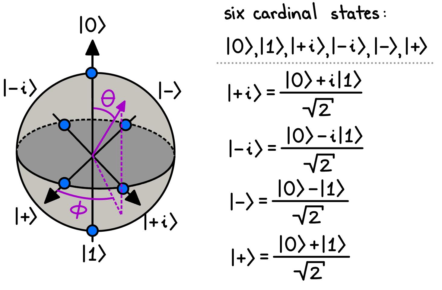
wheretheweights ↵ and � arecomplexscalars.Sincetheprobabilitiesoffinding thequbitinitsgroundorexcitedstateare Pg = |↵|2 and Pe = |� |2 ,respectively,the weightsarenormalizedas |↵|2 + |� |2 =1.Itishelpfultovisualizethesequbitstates onthesurfaceoftheBlochSphereasshowninFig.2.6.
IntheBlochsphererepresentation,wecanseeacleargeometricmappingbetween thepositionofthestateontheBlochsphereifwerewriteourqubitstateas
where ✓ isthepolarangleand � istheazimuthalangle.Notethatorthogonal qubitstatesareantipodalontheBlochsphere!Representingthestatesofaqubit thiswayallowsforthechangesofthestateofthequbittoberepresentedasrotations
Figure2.6:TheBlochsphereforageneralqubit.Thebluecirclesindicatethesix cardinalstates: {|0i , |1i , |+i , |�i , |+ii , | ii}.Thepurplelinesindicatethepolar angle ✓ andtheazimuthalangle � alongtheBlochSphere.
OnemustbecautiouswiththeapproximationbyaTLS,asthevalidityofthe approximationdependsonthetransitionamplitudetohigherstatesbeingnegligibly small.Thisisespeciallytruewhentheanharmonicityissu�cientlylargeand g ⌧
|!q !c | ⌧ EC
Withinthetwo-levelapproximation,thecoupledsystemcanbedescribedbythe quantumRabimodel(QRM),characterizedbytheRabiHamiltonian:
whereˆ �i representsthe i-componentofthePaulispin- 1 2 matrix.WithintheQRM, itiscommontoapplyarotatingwaveapproximationontheinteractionHamiltonian andignoresimultaneous(de)excitationsofthequbitandCPWresonator,asthe termsexchangingenergybetweenthetransmonandCPWresonator( h
(ˆ
)) nearlyconserveallenergy,andthecounter-rotatingtermsarerapidlyrotatinginthe interactionpicture.Neglectingthecounter-rotatingtermsistypicallydonewhenthe
energyrequiredtoexciteboththequbitandCPWresonatorismuchlargerthanthe couplingstrengthandenergydi↵erencebetweenthem: !q + !c � g, |!q !c | [63].
Atthispoint,wearriveatthewell-knownJaynes-CummingsHamiltonian:
ThestrengthofthisHamiltonianformisthatitisanalyticallysolvable[53].
2.2 ConsequencesoftheQubit-CavityCoupling WehaveseenthatcouplingtheCPWresonatortothetransmonallowsforinteraction betweenthetwo.Thisinteractiongivesrisetovariousnon-triviale↵ects.Toillustrate thesee↵ects,wewillusethesimplestmodel—theJaynes-Cummingsmodel,asit providesananalyticallysolvableform.
Whenatransmoniscoupledtoaresonator,suchasaCPWresonator,thestates ofthetransmonandthephotonnumberstatesoftheCPWresonatorarenolonger thesystem’seigenstates[38].Instead,weconsider‘dressed’eigenstateswithshifted energies.Thereareprimarilytworegimestoconsider—theresonantregimeandthe dispersiveregime.Inthisthesiswork,wewillonlyconsiderthedispersiveregime.
DispersiveCoupling Inthedispersiveregime,thedetuningbetweenthetransmonandCPWresonator frequencyismuchlargerthantheircouplingstrength: |�qc | � g .Inthisregime,there islittletononeoscillatoryenergyexchangesincethetransmon’sexcitationenergy doesnotmatchtheCPWresonatorresonantfrequencydeterminedbyitslengthand geomtry.Instead,virtualphotonsmediatethedispersiveinteraction,leadingtoshifts inthesystem’seigenstates[63].Theinteractioncanbeanalyzedthroughaunitary Schrie↵er-Wol↵ transformation:
[62,64].Tosecondorderin g ,thetransformedJaynes-CummingsHamiltonian becomes:
Thecouplingtermisreplacedbyastate-dependentfrequencyshift � =
2 /�
, knownasthedispersiveshiftorACStarkshift.Thiscanbeinterpretedasashift inthetransmonfrequencydependingonthenumberofphotons,orasashiftinthe CPWresonatorfrequencydependingonthequbitstate[36,55,62].Thisphenomenon enablesaquantummeasurementtechniqueknownasquantumnon-demolition(QND) measurement[65],wherethestateofthetransmoncanbeinferredbymeasuring aCPWresonatorknownasthereadoutresonatorwithoutalteringthetransmon’s state.Forthisreason,wewillbeaddingthereadoutresonatorstothedesignforeach auxiliaryqubit.
Howcanweunderstandthisfrequencyshiftphysically?Wehavenotaltered thegeometryoftheCPWresonator,whichretainsthesamelengthandconfigurationofopen-ends.Thesubtletyofthise↵ectliesintheboundaryconditionsofthe CPWresonator’selectromagneticfield.Thepresenceofthetransmonmodifiesthe boundaryconditionsattheopenendoftheCPWresonatorbyalteringtheelectric fielddistributionthroughinductiveandcapacitiveloading.Thisinteractiona↵ects thestandingwavepatterns,changingthee↵ectiveimpedanceandthustheresonant frequenciesoftheCPWresonator.Asaresult,thefrequenciesatwhichtheCPW resonatorresonatesshift.
BeyondtheJaynes-CummingsModel Calculatingthedispersivelevelshiftsofamulti-leveltransmonqubitanalytically iscomplex,partlybecausethecouplingstrengthvariesbetweendi↵erenttransmon energylevels.Whileperturbativeformulasexist[54]toestimatetheshiftedenergy levels,theymaylacktheprecisionrequiredforapplicationsdemandingaccuraciesof upto100kHzoreven10kHz.
Threekeypointsshouldbenoted:
1. ResonantFrequencyShifts: Thedressedenergylevelsofadispersivelycoupledtransmonqubitand[65]areshiftedrelativetothebareenergylevels, regardlessofwhetherthetransmonismodeledasaDu�ngorKerroscillator.
2. ModelDependence: Themagnitudeanddirectionoftheseshiftsdependon thespecificmodelusedtodescribethesystem.
3. QNDMeasurements: Duetothesedispersiveshifts,quantumnon-demolition (QND)measurementisnotuniquetotheJaynes-Cummingsmodelandcanalso berealizedusingtheDu�ngandKerrapproximations.
2.3 InteractionwiththeEnvironment Ideally,wewouldliketohaveadual-railquantumprocessorthatiscompletelystable, withtransitionfrequenciesthatdonotchangeovertimeandarenota↵ectedbythe environmentasitisassumedinthehigh-levelbosonicsimulationsinChapter4. Yet,theprocessorshouldhaveanopenporttotheoutsideworldthroughwhich wecanmeasureandcontrolitsstate.Inreality,nosystemiseverentirelyisolated fromtheoutsideworld.Moreover,ifoursystemwerecompletelyisolated,itwould alsobedecoupledfromourmeasurementinstrumentsandtherewouldbenoway togaininformationaboutit.Decouplingfromnoisesourcesandstrongcouplingto
ourmeasurementinstrumentsandcontrolelectronicsisoneofthemainexperimental challengesintransmonandsetupdesign[39].Theinteractionwiththeenvironment, whichcanbemodeledasabathwithmanydegreesoffreedom,inherentlyleadsto noiseinourmeasurementsinanunpredictableanduncontrolledway[70].Theloss ofinformationintotheenvironmentduetothecouplingtofluctuationsinitiscalled decoherence.Inmathematicalterms,Hamiltoniandynamicspreservesthepurityof thewavefunction,whereasthecouplingtotheenvironmentcausesthedensitymatrix ⇢ tobemixed,leadingtofundamentaluncertaintyaboutthequantumstateour systemisin.Therearetwocontributionswithcharacteristictimescalesthatleadto thislossofcoherence—depolarizationanddephasing.
2.3.1 Depolarization DepolarizationistheundesiredanduncontrolledchangeofthetransmonorCPW resonatorstate[70].Thenameoriginatesfromthetwo-levelatom,whereits |g i and |ei statesarerepresentedbythepolesontheBlochsphere.Whentheatomis initiallyinitsexcitedstate,itcanspontaneouslyloseitsenergybyemittingaphoton andfallingbacktoitsgroundstate.Ontheotherhand,ifnoisesourcesfromthe environmentareofsu�cientlyhighfrequencynear !ge ,theatomcanabsorbaphoton ofthisfrequencyandbecomeexcited.Obviously,theseprocessesarenotuniquefor atwo-levelatom,butholdaswellforthedi↵erentpossibletransitionsofamore realisticmulti-leveltransmonqubitandCPWresonator.Inthecaseofareadout resonatorconstructedalsofromaCPWresonator,forexample,thetransmissionline willnotbeperfectlytransparent,andphotonsmayescapefromthefeedline[71].
Thetotaldepolarizationrateisgivenbythesumoftheabsorptionrate �" and theemissionrate �# [72]:
Inthequantumlimit,thenegativeandpositivefrequencycontributionofthe spectralnoisedensityisasymmetric.Therefore,therelaxationrate �# andabsorption rate �" canbedi↵erent.Tocontrolandevaluatethesystem’sstate,thestatesare requiredtobesu�cientlylong-livedcomparedtothemanipulationtimes.Sowe havetoenhancetodepolarizationtime T1 =2⇡ /�1 .Tosuppresstheabsorption bythequbitandCPWresonator,wecooldownthesystemtoverylowcryogenic temperatures(10mKinoursetup),where kB T ⌧ ~!0 .Withthethermalnoise exponentiallysuppressed, �" ⇡ 0and �1 ⇡ �# .Thatiswhythedepolarizationrate iscommonlyreferredtoastheenergy(orlongitudinal)relaxationrate.
SystemsthatshowmultipleRabicyclesbeforetheenergyislosttotheenvironmentaresaidtooperateinthestrongcouplingregime,thatis g � �1 .Thecoherent interactionbetweenthequbitandtheresonatoristhedominantformofinteraction. Intheoppositeregime,where g< �1 ,theinteractionisbasicallyincoherentanddominatedbythedampingrates �1 and 1 .Circuitsetupsprovidetheeasypartofstrong qubit-resonatorcouplingfortheRabicycles,manipulation,andreadout.Themore di�cultpartistheclosetoperfectlyshieldingofthechipfrominteractionswiththe environmentsothatdissipativelossissuppressedandquantumvacuumfluctuations donottriggerspontaneousemission[53].
2.3.2
Dephasing Dephasingistherandomizationofthephasedi↵erencebetweentwoeigenstates[73]. Thedephasingrate �� isacombinationofthedepolarizationrate �1 andthepure dephasingrate �' : �� = 1 2 �1 + �' (2.37)
Depolarizationisincludedbecausethecoherentsuperpositionoftwoeigenstates,
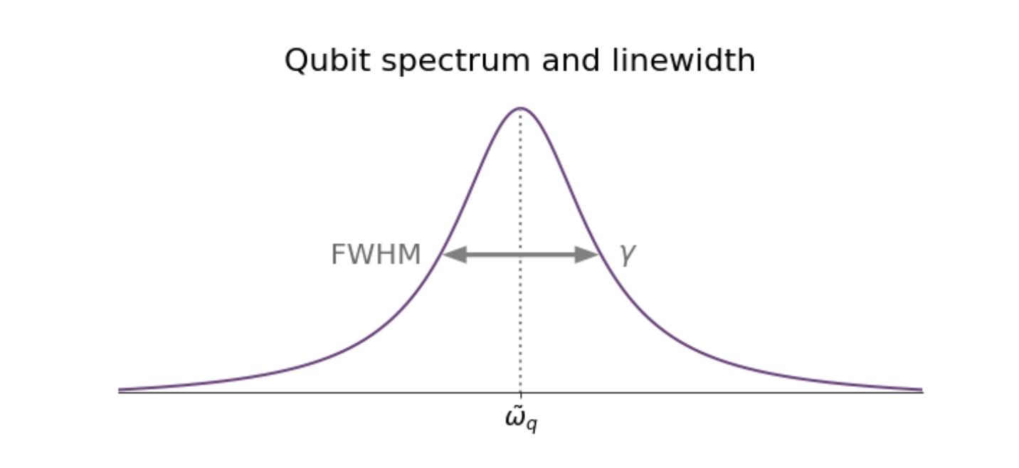
say |g i and |ei,isdestroyedifthequbitmakesatransitionbetweenthem.Thepure dephasingarisesfromadiabaticfluctuationsintheenergyspacingbetweentwoeigenstates.Thelatterisnon-dissipative,soitdoesnotinvolveanyenergyexchangewith theenvironment.DephasingusuallygivesthequbitandCPWresonatorspectrum theirfinitelinewidth,whichwedefineasthespectrum’sfull-width-half-maximum (FWHM,seeFig.2.7).
Figure2.7:Lorentzianshapeofthequbitspectrum.Thelinewidth � arisesfrom thedephasingrateandisdefinedbythefull-width-half-maximum(FWHM)ofthe spectrum.
Here,weshoulddistinguish �2 from �⇤ 2 .Wheretheformerdescribesanintrinsic timescaleforthedecoherence,thelatterisameasureforanensembleofrepeatedly performedmeasurements.Fluctuationsonthetimescaleofatleastonemeasurementthenresultindi↵erentconditionsfordi↵erentmeasurements,whichreduces theactualobserveddecoherencetimefrom T2 =2
2 to T
2 =2
/�
2 [73]. T ⇤ 2 isassociatedwithbothhomogeneousandinhomogeneousbroadeningofthespectrumand canbemeasuredbyaRamseyexperiment[74]. T2 canbedeterminedbyspin-echo measurements[75],whicheliminatetheinhomogeneousbroadeninge↵ects[55].
2.3.3 TimeEvolutionofanOpenQuantumSystem Thetimeevolutionofthestateofanopenquantumsysteminteractingwithits environmentcanbecompletelydescribedbytheLindbladmasterequation(LME).
Thedynamicsarecapturedbythedensitymatrixˆ ⇢,Hamiltonian ˆ H ,andcollapse operators ˆ Cn as
[76].Weseethatthestateofthesystem,describedbyˆ ⇢,evolvesinaunitaryway (throughtheLiouvillian)andanon-unitaryway(throughtheLindbladian).TheLiouvilliandescribestheevolutionofthequbit-resonatorsystemasifitwerecompletely disentangledfromtheenvironment.Thenon-unitarypart,ontheotherhand,does representtheinteractionwiththeenvironment,leadingtoalossofcoherence.The collapseoperators ˆ Cn quantifythedissipationanddephasing.
Tosimulatethetimeevolutionofopenquantumsystemslikequbitsandresonators,wecanusetheQuTiP(QuantumToolboxinPython)libraryparticularly inChapter4.QuTiPprovidese�cientmethodstosolvetheLindbladmasterequation,allowingustomodelthedynamicsofquantumsystemsundertheinfluence ofenvironmentalinteractions.Itcansimulatetheevolutionofthedensitymatrix, trackpopulationchanges,andstudythee↵ectsofdi↵erentnoisesourcesandcontrol fields,makingitanessentialtoolforexploringquantumcoherenceanddecoherence inrealisticsettings.
3 DesignandAnalysis Animportantdecisionmadeatthebeginningoftheprojectwastouseofpairof CPWresonators,collectivelyknownasdual-railsinsteadofindividualCPWresonators.Eachdual-railiscoupledtoaflux-dependentauxiliarytransmonknownas superconductingquantuminterferencedevice(SQUID)usedforquantumstatecreation,statemanipulationandstatereadout.Similartoatransmon,aSQUIDconsists oftwoJosephsonjunctionsconnectedinparallel,whichformasuperconductingloop, shuntedbyacapacitance.Forthecouplerbetweenthetwodual-rails,weoptedfor asuperconductingnonlinearasymmetricinductiveelement(SNAIL).Theadvantage ofusingaSNAILliesinitsabilitytosuppressundesiredfrequencyshiftimpartedby theJosephsonjunctions[21].Thisproblemisanalogoustothatgeneratedby �(3) mediainnonlinearoptics[96].ThesuppressionisengineeredbycreatinganasymmetryintheinductancebetweentheJosephsonjunctionscomposingtheSNAILwith threadedmagneticfield.However,inordertothreadmagneticfieldintheSNAIL, theSNAILmustbecoupledtoafluxline,asitissimilardonewiththeSQUIDs, whichposesthedisadvantageofincreasingthetransmonsexposuretoexternalnoise andpotentialdecoherence.Toaddressthisexperimentalchallenge,wechosetoadd slotlinesbetweenthefluxlinesandtheJosephsonjunctionscomposingtheSQUIDs andSNAIL.
Todevelopacomprehensivedesign,simulation,andoptimizationflowforthe experimentonthechip,weutilizedarangeofbothopen-sourceandclosed-source softwaretools.Thisincludestheopen-sourcesoftwaresQiskitMetal,QuTiP,and SCQubitsandtheclosed-sourcesoftwareANSYSQ3DandANSYSHFSS.Although open-sourcecapacitanceextractionsoftwareexistthatcanreplicateANSYSQ3Dsuch asElmerFEM[77],currently,noopen-sourcesoftwareexistsforeigenmodedesignand optimizationthatcanreplicatetoANSYSHFSS.E↵ortsareongoing[82]todevelop acompleteopen-sourceeigenmodesimulator,whichwouldexpandtheaccessibility ofquantumprocessordesigntothosewhodonothaveaccesstoexpensivesoftware
suites.
3.1 QiskitMetal QiskitMetal(Metal)isaPython-basedsoftwarepackagewithinQiskitdesignedto facilitatethedesignlayoutandelectromagneticsimulationofsuperconductingqubits. ItallowsuserstocreatequbitdesignsfromscratchandexportthemasGDSfilesfor fabrication[83,84].Metalcontainsmultiplemodelsofsuperconductingcomponents andallowstheusertoconstructtransmonsdesignsfromscratch.Theusercancustomizetheprecisedimensionsofeachcomponentofthetransmon,suchastheshunted capacitorsize,aswellasthedimensionsthecouplersbetweenthetransmonandthe CPWresonatorandbetweenpairofCPWresonators,asshowninFig.3.1andFig. 3.2.Oncethemaintransmondesigniscompleted,theCPWresonatorcanthenbe coupledbyadditionalCPWresonatorstocreateadual-rail.Metalthenallowsforthe designtobeexportedtocommonelectromagneticrendererssuchasANSYSQ3D.
Metalhasseveralanalyticaltechniqueswhichcanbeusedforcriticalparameter extractioninconjunctionwithelectromagneticsimulationincludingEnergyParticipationRatio(EPR),impedancescatteringandLumpedOscillatorModel(LOM). ThesetechniqueshoweverhavelargelybeenoptimizedforthefullversionofANSYS andonlylimitedtechniquesexistinMetalforanalysisutilizingotheropen-source renders.OnesuchmethodintheLumpedOscillatorModel(LOM)analysis,which usestheextractedcapacitancematrixfromanelectromagneticrenderertoconstruct acompositesystemHamiltonian,whichcanthenbeusedinquantumsimulation softwaretoextractcriticalqubitparameters.
Figure3.1: TransmonCross:Transmonwithadjustabledimensions.
Figure3.2: CapInterdigital:Interdigitalcapacitorwithadjustabledimensions.
3.2 SinglePlanarDual-RailQuantumProcessor Design
3.2.1 DesignConsiderations Whendesigningaplanardual-railquatumprocessor,therearemanydesignsconsiderationtobetakenintoaccount.TheseincludethephysicaldimensionsofeachCPW resonatorscomposingthedual-rail,thematerialsusedinfabrication,thedimensions ofeachtransmoncoupledtothedual-rails,thedimensionofthecouplerbetweenthe dual-railsamongmanyotherfactorswhicha↵ecttheendperformanceoftheprocessor.Duetothecomplexityofthedual-railquantumprocessor,itisthensimplestto beginwiththeessentialbuildingblock—asingledual-rail.
Asingledual-railconsistsoftwoCPWresonatorscoupledtoSQUIDauxiliary transmons.Theprimarydesignconsiderationsaretheparametersthathavethe greateste↵ectonthedual-railperformance,suchasthetransmonresonantfrequency !q ,anharmonicity ↵,theCPWresonatorresonantfrequency !r ,thecouplingcapacitancebetweenthetransmonsandtheCPWresonators Cq,CPW ,andthecoupling capacitancebetweenthepairofCPWresonators CCPW,CPW .Eachoftheseparametersisdeterminedbythephysicallayoutofthe TransmonCross showninFig.3.1for thetransmonand CapInterdigital showninFig.3.2fortheCPWresonators.As discussedinSection2.1.3,onecanoperateasuperconductingqubitinthetransmon regimebyensuring EC ⌧ EJ .Inpractice,thisisaccomplishedbyincreasingthecross lengthorcrosswidthofeach TransmonCross.Thisincreaseincapacitanceisdueto thelargercapacitancecouplingbetweenthe TransmonCross crossandtheground Additionally,alteringthecapacitanceofthe TransmonCross ortheinductanceofthe Josephsonjunctionchangesthe !q ofthetransmon.Therefore,thesemodifications mustbemadewithcarefulconsiderationtoensurethatthe !q ofthe TransmonCross isthetargetfrequency.
Anotherimportantdesignconsiderationisthecouplingcapacitance g betweenthe transmonandCPWresonatorandbetweenthepairofCPWresonators.Asshown
inSection2.2,gisdependenton Cq,CPW and CCPW,CPW ,respectively.Thisallows ustodesign g byaltering Cg .Thiscouplingstrengthinturndeterminesthequbits relaxationtime T1 anditsdephasingtime T2 makingitimportantconsiderationswhen designingadual-railquantumprocessor,astheydeterminethee↵ectivelifetimeof thetransmonanddual-railquantumstate.
3.2.2 ProcessorDesigninMetal Designingasingledual-railprocessorinMetalismoste�cientlydoneusingaJupyter Notebook.Thefirststepinthedesignprocessistodefinethetypeofchiptobe built.Metalprovidesseveraldesignoptions,includingplanar(2Dchip),multiplanar (multi-layered3Dchip),andflip-chipdesigns.Foraplanardual-railquantumprocessor,eitheraplanarormultiplanarchipcanbechosen,withminimaldi↵erencein resultsduringthecapacitanceextraction.Consideringthatthequantumprocessor isfabricatedwitha250nmlayerofaluminum(Al)ona350 µmsiliconsubstrate,a 2Dplanarsimulationcapturestheelectrodynamicsofthesystem.
Figure3.3:CreatingaDesignPlanarobjectandinitializingitsGUI
Thesizeofeachchipcanbeexplicitlydefinedorsettoitsdefaultdimensions.
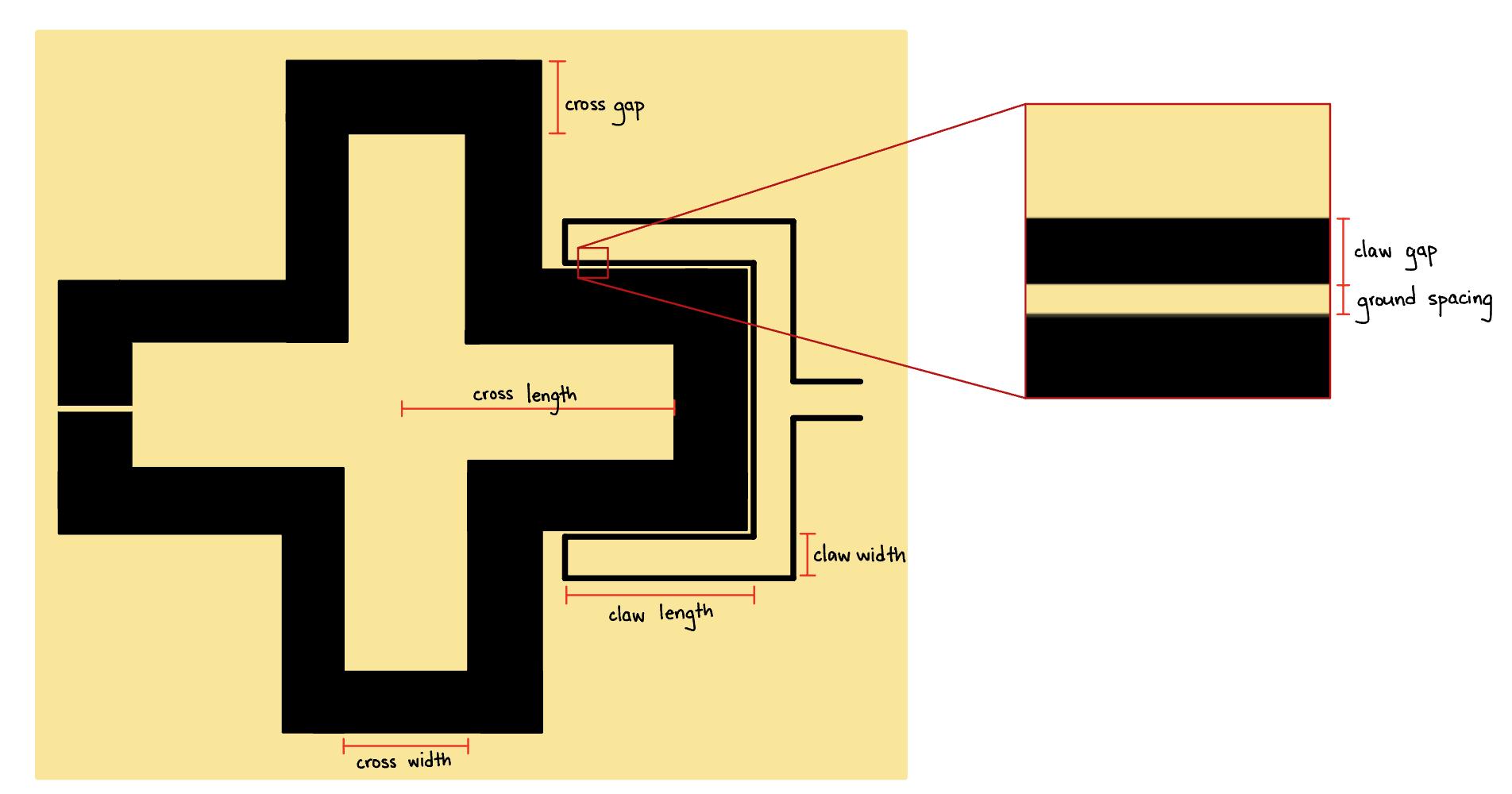
TransmonCross canthenbeaddedtothedesignbycallingthe qubit classinsidethe library qlibrary andpassingargumentstodefinethe TransmonCross dimensions andrelativepositiononthechip.Whena TransmonCross isadded,itisplacedwith agroundplanesurroundingit,whichisconnectedtothegroundoftheCPW.The heightandwidthofthegroundplanegaparereferredtoasthe cross gap.The heightandwidthofthecross-shapeislandarereferredtoasthe cross length and cross width,respectively.Byadjustingthe pos x and pos y options,whichdefine theo↵setofthecenterofeach TransmonCross fromtheoriginofthechip,onecan
preciselyplaceeachtransmononthechip.Additional,interdigitalcapacitorsthat comesincludedin TransmonCross asshowninFig.3.1,whichwehavenicknamesthe “claw”,canbeaddedfortransmon-CPWresonatorcouplingbypassingadictionary to connection pads.Theclawnotonlycouplestheresonatortothetransmonbut alsoaddssignificantgeometriclengthtotheCPWchangingitsresonancefrequency !r tobeconsideredlaterduringeigenmodedesignandoptimization.Whendefining connectionfingers,itisimportanttonotethattherearetwotypesof connector type: ‘0’fortheclawcoupleror‘1’foralinecoupler.Thoughtnotshowninthisprocedure, thelinecoupleristhetypeofcouplerwewanttouseforthedrivelinescoupledto eachSQUIDauxiliarytransmon.Thestandard TransmonCross supportsuptothree connectionfingers(oneconnectionpercrossarmexpectthearmwherethejunctionis located),and connector location defineswhichofthreearmsthe TransmonCross addstheclaw.Foradditionaloptionsforthe TransmonCross,referto[86].An importantthingtonoteisthatatcertaindimensionsoftheclaw,adiscontinuityin theconnectionbetweentheclawandtheCPWiscreatedwithoutanapparentreason.
Bysetting claw cpw length =0,weeliminatethediscontinuitybyforcingtheCPW tocreateadirectconnectiontotheclaw.Anexampleofasingletransmondesignis showninFig.3.4,andtheresulting TransmonCross isshowninFig.3.5.
Nowthatwehavedefinedthedimensionsofthe TransmonCross,wecangoahead andconstructthepairCPWresonatorsthatconstitutesthesingledual-rail.The designoftheCPWresonatorsisstraightforward,andtheprimarydesignconsiderationatthisstageisdefiningalengththatcorrespondstothedesiredCPWresonance frequency.Toaddadual-rail,wefirstpassthe CapNInterdigital componentthat servesasthecouplerbetweenthetwoCPWresonators,creatingtwotermination points.Then,wecanaddasecond TransmonCross toreplicatethesame“claw”couplerforthesecondCPWresonator,creatingthefourthterminationpoint.Sincewe haveintotalfourterminationpoints,wecannowpassapairofterminationpoints toadictionary options() of RouteMeander thatcreatesasingleCPWresonator.
Figure3.4:Metalcodeforgeneratinga TransmonCross
Figure3.5: TransmonCross designinMetal.
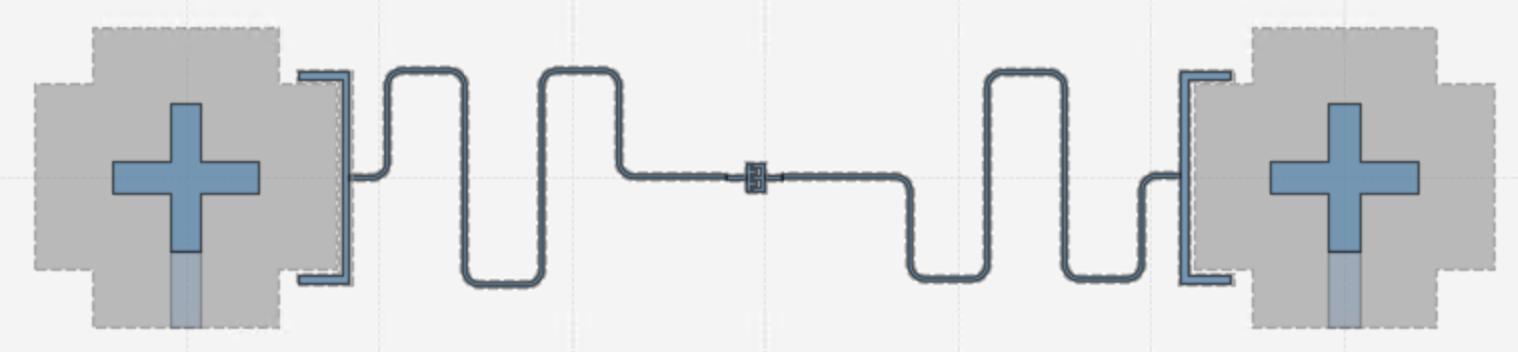
Thesamedictionary options() alsoincludesthedefinitionofthelengthoftheCPW resonator total length,theradiusofthecurvature fillet,andthedirectionofthe meanderswithrespecttotheassignedstartpin asymmetry.Anexampleofsample codedefiningameandereddual-railwithlengthof2.5mmforeachCPWwithclaw couplerstotwotransmonisshownFig.3.6,withtheresultingdual-railshowninFig. 3.7.
Figure3.6:Metalcodeforgeneratingadual-railsystemcoupledtotwoauxilliary TransmonCross.
Figure3.7:Dual-railcoupledtotwo TransmonCross showninMetalGUI.
3.3
ANSYSHigh-FrequencyStructure(HFSS)Anal- ysis
ANSYSHFSSisoneofthemostcommonsoftwaretoolsusedinelectromagneticsimulationsforsuperconductingqubitsandotherhigh-frequencycomponents.Itprovides adirectwayofdoingaccurate3Dmodelingandsimulationofsuperconductingcircuits.ThemaincapabilitiesofHFSSinthisthesisworkistheeigenmodesimulation oftheCPWresonatorsconsideringtheircomplicatedgeometriclengthaddedbythe clawcouplers.
3.3.1
HFSSAnalysisConsiderations BeforeperformingLOManalysistocharacterizethetransmon,itisusefultofirst determinetheresonancefrequency !r oftheCPWs.TheCPWresonancefrequency !r isincludedintheconstructionofcompositeHamiltonianofthedeviceduring theLOManalysis,whichcharacterizesthetransmonresonantfrequency !q andthe anharmonicity ↵
ANSYSHFSSo↵erstwomajortypesof3Delectromagneticanalyses:
1. DrivenModalAnalysis:Thisinvolvesexcitationviawaveports,whereenergyissuppliedtothestructurefromanexternalsource,yieldinginternalfields andportS-parameters.Adefinedfieldatagivenportboundaryisappliedas
excitationforthe3Delectromagneticstructure,causingelectromagneticfields tobuildupinthestructureandpropagatetootherports.
2. EigenmodeAnalysis:Thistypeofanalysisperformsan‘undriven’analysiswithnoexternalpowersourceinvolvedandnowaveportsused.Acertain amountofstoredenergyisassumedtobe“trapped”inthestructure,andthe eigenmodesolverrevealstheresultingmodesandtheirfieldproperties.
Fortheplanardual-railquantumprocessor,bothtypesof3Delectromagnetic analysisworktofindtheresonantfrequencyofthedual-rail.Nevertheless,onlythe eigenmodeanalysisisintegratedwithintheJupyterNotebookenvironmentandwill betheoneweuseinthefollowingsection.Thedrivenmodalanalysiswillbeused laterintheSection3.6.2tofindS-parameterandimpedancebehaviorofacomb-like couplerusedbetweenaPurcellfilterandfeedline.
Furthermore,theeigenmodeanalysisisknowntobeabledtosolvetheresonant frequenciesofnotonlyCPWresonatorsbutalsofortransmons.Neverthless,wewill usethecompositeHamiltonianconstructedintheLOManalysisformorecomprehensiveunderstandingofthedevice.Furthermore,theeigenmodeanalysisisknown tobeabledtosolvetheresonantfrequenciesofnotonlyCPWresonatorsbutalso fortransmons.Neverthless,wewillusethecompositeHamiltoniantoderivethese variables
3.3.2 ProcessorAnalysisinANSYSHFSS
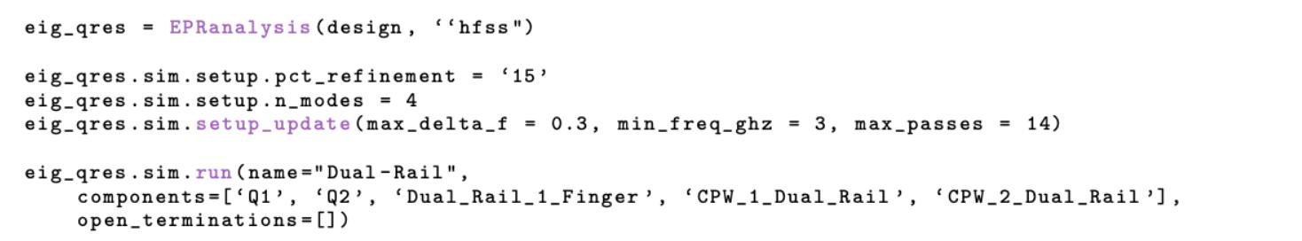
Inordertosetuptheeigenmodeanalysis,wefirstcreatean EPRanalysis classwhere weinputthename design ofthequantumprocessorwenamedinFig.3.3.The secondinputofthe EPRanalysis specifiesthetypeofsimulation hfss whichisdefaultedforeigenmodeanalysis.Thequantumprocessorrenderingandeigenmode analysissimulationcanbeoptimizedwith pct refinement standingforpercentage
refinement.ThisparametercontrolsgranularityofthequantumprocessorasitrendersinANSYSHFSS.Arefinementlevelof15hasbeenfoundtoprovideaccurate resultscomparingfromexperimentaldata,althoughhigherlevelscanbeemployedfor greateraccuracyespeciallyfortherenderingofbiggerstructureswiththetradeo↵ of increasedcomputationalcomplexityandlongersimulationtimes.Anotherimportant parameteris n modes,whichdeterminesthenumberofmodestobeidentifiedinthe simulation.Giventhatthesystemhastwo TransmonCross andtwo RouteMeander, thesimulationcanbeaimedtoresolvefourmodestocapturethefundamentalmode ofthetwotransmonandthetwolowestspatialmodefrequenciesofthedual-rail.An additionalcriticalparameteris max delta f=0.3,whichcontrolswhenthesimulationstopsbasedonfrequencyconvergence.Ifthesimulationresultsinfrequencies di↵erencehigher0.3GHz,thesimulationwilleitherrefinethemeshfurtherbasedon the pct refinement orstopifithasreachedthemaximumnumberofpasses.Bysettingthisparameter,theconsistencyofthesimulationiscontrolled,ensuringthatthe resultsbetweeneachpassarewithinasmallmarginoferror.Similarly,theparameter min freq ghz=1 GHzestablishestheminimumfrequencyatwhichthesimulation beginsfindingresonantmodesinthechip.Forinstance,settingthisminimumfrequencyto10GHzwouldexcludetheelementwithresonantfrequencieslowerthan 10GHz.Theparameter max passes=30 definesthemaximumnumberofpassesif the max delta f isnotmet.Theseparametersareconsideredduringtherenderingof the design toANSYSHFSSasshowninFig.3.8,withthefirstfourlowestresonant modesofthechipvisualizedinFig.3.9(a)andfrequenciescorrespondingtoeach modedisplayedinFig.3.9(b).Additionalparameterscanbedefinedandexamined byrunningthecommand eig qb.sim.setup
Figure3.8:Metalcodeforsettingupandrunningasimulationforadual-railsystem inHFSS
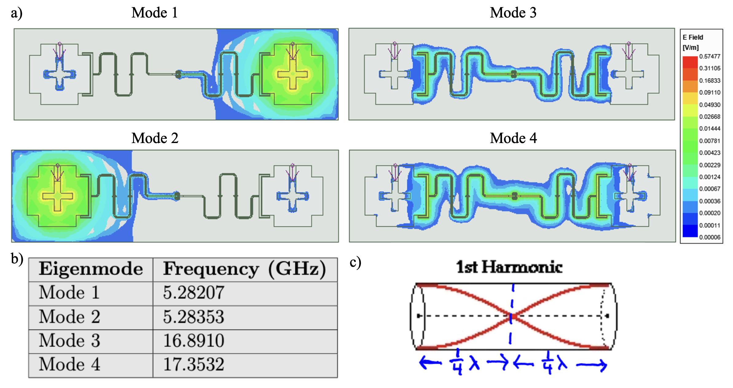
Figure3.9:(a)PlotsoftheeigenmodesobtainedusingHFSSforthedualrail chip design,showcasingthedistributionofelectromagneticfieldsfortetwo TransmonCross andthetwo RouteMeander.(b)Frequenciescorrespondingtoeach resonantmodefromANSYSHFSS.Both TransmonCross hasJosephsonJunction withinductanceof10nHandhavealmostidenticalresonantmodeasreportedin Mode1andMode2.The500MHzdi↵erencebetweenthesetwomodes,despitethe dual-railshavingthesameresonatorlengthandgeometry,istheresultofhybridization.(c)Illustrationofthefirstharmonicmodeforanopen-endharmonicoscillator, highlightingthedistributionofnodesatthecenterpointandantinodesattheopen endofthelengthharmonicstructure.
NotethatMode3andMode4inFig.3.9(a)representthetwolowestfundamental resonantmodesofthedual-railwiththenodesandantinodesplacementcharacteristic of � 2 resonatorsasshowninFig.3.9(c).ThehybridizationofMode3andMode 4isstronglydependentonthecouplingstrengthbetweenthepairof RouteMeander
definedbythe CapInterdigital inFig.3.6.
Withthefundamentalresonantfrequencies !r ofthedual-railfound,weareready tocharacterizethetransmonusingLOManalysis.
3.4 LumpedOscillatorModel(LOM)Analysis 3.4.1
LOMAnalysisConsiderations TheLumpedOscillatorModel(LOM)isaquantizationmethodusedtoextractcritical Hamiltonianparametersofaquantumsystem.TheLOMatitscoresetsoutto extractcriticalparametersforseparateunitswithinthequantumsystem,knownas subsystems.Eachsubsystemisanalyzedindependently,andthecriticalHamiltonian parameters,suchasthechargingenergy Ec andanharmonicity ↵,areextractedby analyzingtheircompositeHamiltonian.ThefullsystemHamiltonian ˆ Hfull ,alsocalled thecomposite-systemHamiltonian,withasubsystemcoupledto K neighborsisthus representedbythesummation:
Here, ˆ H0 istheHamiltonianofthesubsystem, ˆ Hn istheHamiltonianofthe n-th neighbor,and ˆ Hnm istheinteractiontermbetweenthe n-thand m-thsystems.The interactiontermHamiltonianisfurtherdefinedas:
where Cnm and Lnm representthee↵ectivecouplingcapacitanceandinductance betweenthe n-thand m-thsystems,respectively[87,83].
TheHamiltonianoftheCPWisconstructedbydefiningtheresonatorresonance frequencyfoundinSection3.3.2,characteristicimpedance,andphasevelocity.It
hasbeenshownin[87,88]thattheHamiltoniansexpressedinEquations(3.1)and (3.2),alongwiththeresonator-transmoncouplingcoe�cientfromEq.2.21,canbe approximatedusingtheMaxwellcapacitancematrixofeachsubsystem,aswellas theJosephsonjunction’scapacitanceandinductance.Forthisthesis,theJosephson junction’scapacitance,inductance,andenergyhavebeensetto12nHand2fF, whicharethedefaultvaluesprovidedbyMetal.Itshouldbenotedthatthesevalues dependonhowthejunctionisfabricatedandcanbeadjustedinMetaltoreflectthe expectedperformanceafterfabrication.
AfterconstructingthefullHamiltonianofthecompositesystem,itcanbeanalyzedusingquantumsimulatorssuchasQuantumToolboxinPython(QuTiP).These simulatorscanextractcriticalparameters,suchastheresonancefrequency !q and anharmonicity ↵ ofeachtransmon.
TheMaxwellcapacitancematrixdescribestherelationshipbetweenthevoltages andchargesonasetofconductors.Forexample,givenfourconductorswithpotentials
V1 ,V2 ,V3 ,V4 whereeachconductoriscapactivelycoupledtoeachother,thecharge on Q1 canbeexpressedas:
wherethisequationcanberepresentedasthefirstrowofthe4x4capacitance matrix,onerowperconductor:
Using(3.4)andconsideringanarbitrary n numberofconductors,theMaxwell capacitancematrixtakestheform:
3.4.2 ProcessorAnalysisintheLOMAnalysis CapacitanceExtraction TheMaxwellcapacitancematrixforeach TransmonCross canbeextractedsending thedesigntotheelectromagneticrenderingANSYSQ3D.Metalhasstreamlinedthe electromagneticrenderingandLOManalysiswithANSYSQ3D,onlyrequiringafew linesofcodetocompletethe TransmonCross renderingandparameterextraction process.Inordertosetupthecapacitancematrixextraction,wefirstinitializethe q3d renderingwithinthedesignenvironmentnamed Q3dAncillaDesign withthe argument capacitive foracapacitanceanalysis.Wecanspecifytheexactelement torenderusing render design asshowninFig.3.10.Theresultingmeshforthefor Q1 and Q2 isshowninFig.3.11alongwithmethodoverviewofLOManalysisforthe dual-rail.
Figure3.10:CodetoinitializeANSYSQ3Dforcapacitanceextraction
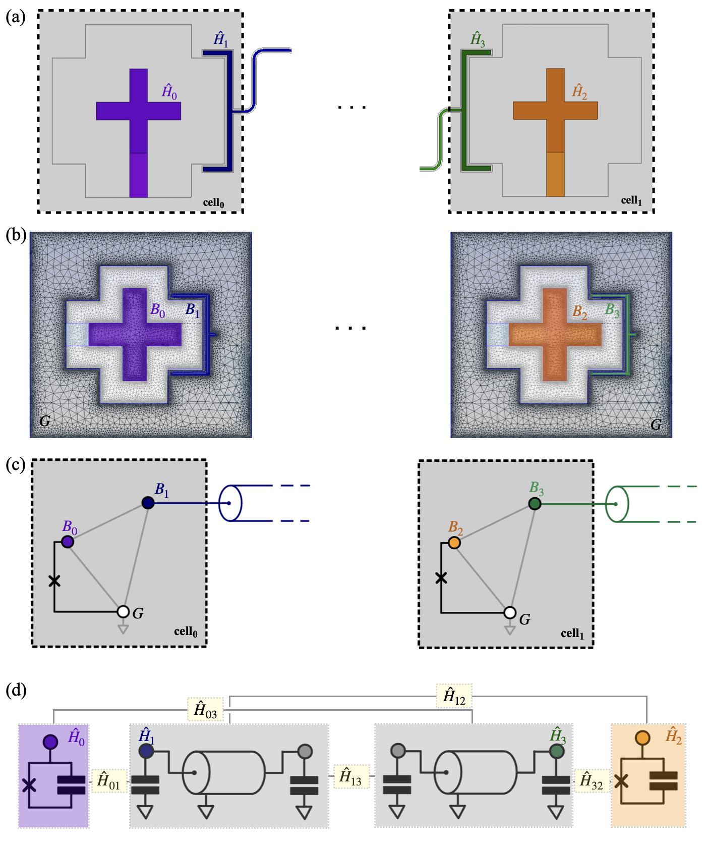
Figure3.11:Methodoverview.(a)Illustrationofthesingledual-railsystem(partial, not-to-scale).Left: TransmonCross 1(purple)withHamiltonian ˆ H0 connectedto CPWwithHamiltonian ˆ H1 .Right: TransmonCross 2(orange)withHamiltonian ˆ H2 connectedtoCPWwithHamiltonian ˆ H3 .Thelayoutisdividedintosubsystems andcells.(b)Examplesimulationmodelofcell0 andcell1 withsimulationmesh. Thecellsincludequbitpads B0 and B2 ,CPWcouplerfingers B1 and B3 ,andthe groundsegment G consideredforthecapacitancematrix.(c)Partialschematicof thecomposite-systemnetworkshowingnodesandelementsofcell 0 andcell1 ,and theirconnectionstoneighboringcells.Nodesarecapacitivelycoupledbyafullyconnectedgraph(thickline).AJosephsonjunctionconnects B0 to G and B0 to G.(d)Depictionofdressedsubsystemsasbuildingblocksandtheirinteractions, describedbyHamiltonians ˆ H01 , ˆ H03 , ˆ H12 , ˆ H13 ,and ˆ H32
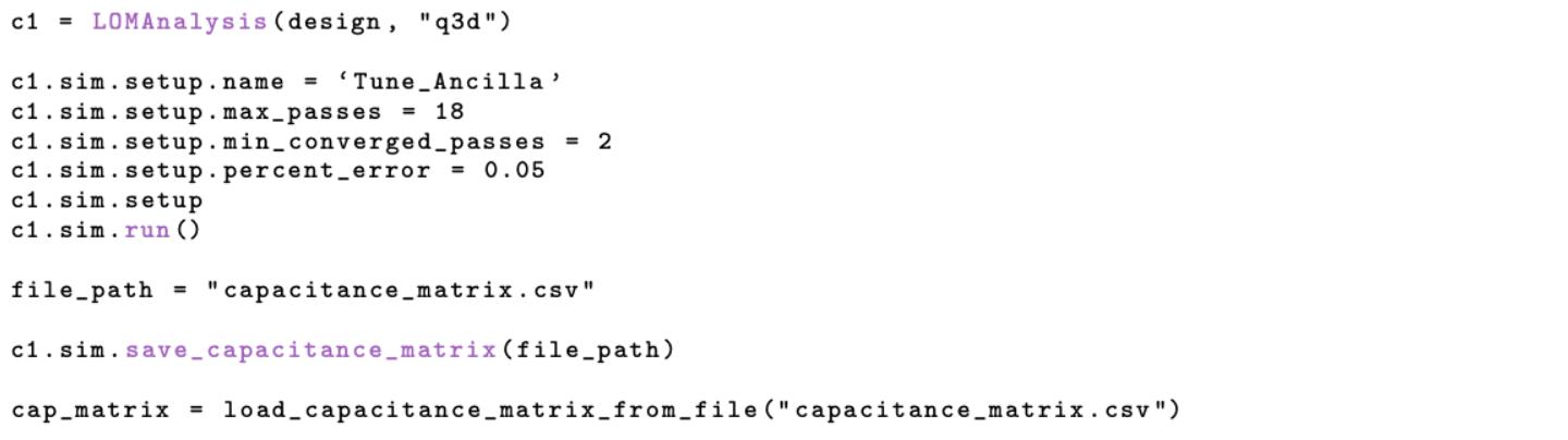
WecancreatetheanalysissetupinsideANSYSQ3Dbycalling LOMAnalysis to specifysimulationparameterssuchasthemaximumnumberofpasses max passes, theminimumnumberofpassesrequiredforconvergence min converged passes,and thepercenterrorforthesimulation percent error asshowninFig.3.12.Thecode alsosavestheresultingcapacitancematrixtoacsvfileforcompatibiltywiththe LOManalysisandtheresultinginthecapacitancematrixisgiveninFig.3.13.
Figure3.12:CodetosetupANSYSQ3Dandextractcapacitancematrix.
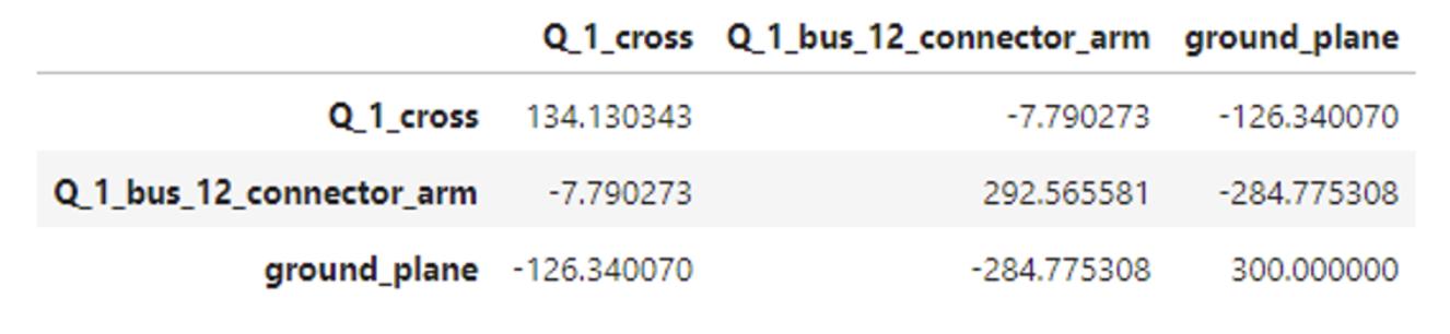
Figure3.13: Q1 capacitancematrix,withvaluesexpressedinfF.
NotethatANSYSQEDplacesdefaultnames Q 1 cross, Q 1 bus 12 connector arm, and ground plane correspondingtothenodes B0 , B1 ,andGrespectivelyinFig.3.11 (c).Thisprocessshouldberepeatedforeachqubitinthesystem,witheachcapacitancematrixsavedasacsvfilebeingsavedfortheLOManalysis.
CompositeSystemHamiltonianConstruction Asdiscussedinsection3.4.1,theLOManalysisisconductedbyconstructingthe compositesystemHamiltonian.ThecompositesystemHamiltonianconstructionin
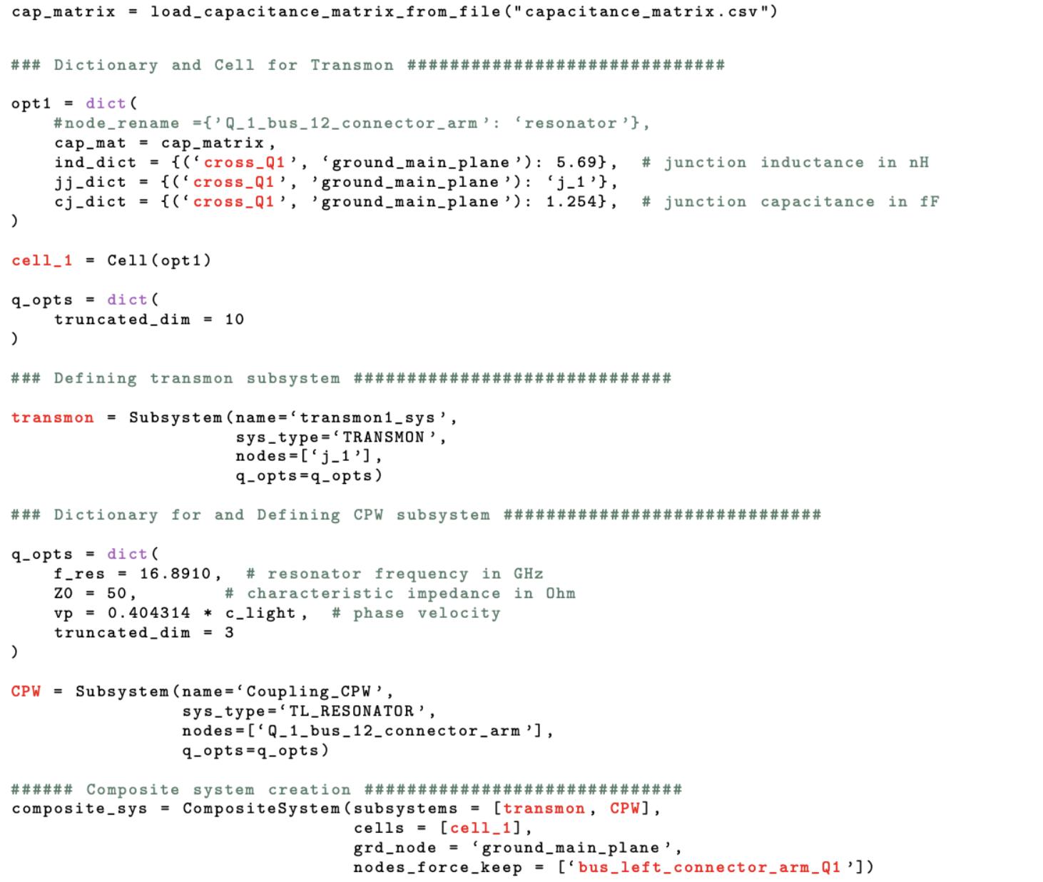
MetalutilizesMetal’ssubpackage lom core analysis,whichincludesclassesthat definethesubsystemforthecompositesystem.Thispackageincludesbuilderclasses whichbuildthetransmonandCPW.Toconstructthetransmonsubsystem,wefirst defineadictionarycontainingthecapacitancematrixsavedfromCapacitanceExtractionsectionandtheJosephsonjunction’sinductanceandcapacitance.Wethenpass thisdictionarytothe Cell classdepictedshowninFig.3.11(a).Next,weconstruct thetransmonsubsystembycallingthe Subsystem classanddefiningthesystemtype as TRANSMON andbydefiningthenodeofthesystem,whichistheJosephsonjunction forthetransmon.Additionalparameterscanbepassedtothesubsystembypassing adictionaryto q opts,suchassetting truncated dim,whichtruncatestheenergy levelsofthetransmontotheprovidedvalue.Itshouldbenotedthatthedefault energyleveldimensionforeachtransmonis10.
Afterconstructingthetransmon’ssubclass,wenowmovetoconstructingtheCPW subclass.Webeginbydefiningadictionarycontainingthefrequency,characteristic impedance,andphasevelocityoftheCPW.Wethenpassthisdictionarytoanother Cell andconstructanewsubsystemfortheCPW.Thesubsystemwehavechosen hereis TL RESONATOR,whichisusedtodefinetheCPW.Additionally,wedefinethe nodesoftheCPW,whichis Q 1 bus 12 connector arm inthecapacitancematrix. Aswiththetransmonssubclass,theenergylevelsoftheCPWcanbechangedfrom theirdefaultof3bypassinganewvalueto truncated dim.
Lastly,weconstructthecompositesystemobjectbycallingtheclass CompositeSystem andpassalistofthesubsystemsandcells.Additionally,wedefinedthegroundnode asthegroundplane(ground plane)inthedesign.Thecodetoconstructacomposite systemofonetransmontransmonscoupledbyaCPWisshowninFig.3.14.
Figure3.14:CompositesystemconstructionforonetransmonscoupledbyaCPW.
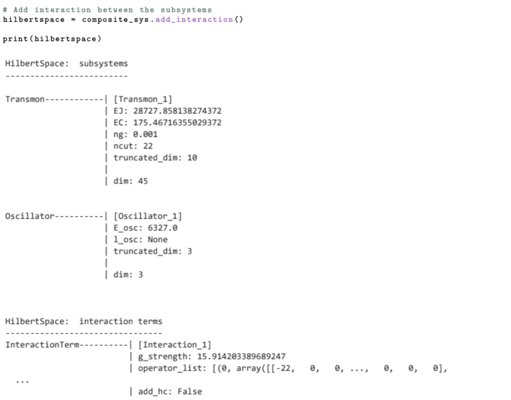
ThecompositesystemobjectconstructedinthecodeabovemustnowbeconvertedintoafullcompositesystemHamiltonian,suchasinEquation3.1.Todo thiswemustfirstaddtheinteractionterms,describedby(3.2).Thisisdonein astraightforwardmannerbycallingthemethod add interaction ofthecompositesystemobject.Whencallingthismethod,MetalwillfirstconstructaSCQubits hilbertspace object,formingtheHilbertspaceoftheonetransmonandCPWonly, whereSCQubitsisaquantumsimulatorshownin[89,90].Next,Metalwillcalculate theoscillator-transmoncouplingconstant g forthecouplingpadoneachtransmonby callingthe compute gs methodofthe CompositeSystem class.Finally,Metalwilladd theinteractiontothe hilbertspace objectbycallingthe add interaction method.
Theresulting hilbertspace objectcanthenbeprintedtoshowsomeofthecritical parametersforthecoupledtransmons,reportedinMHz,asshowninFig.3.15.
Figure3.15:Criticalparametersprintedfrom hilbertspace object.
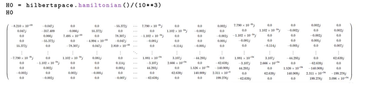
TheresultingfullcompositeHamiltonian,includingtheinteractionterms,can thenbedisplayedfromthe hilbertspace objectbycallingthehamiltonianmethod. Theresultisa Qobj whichisaquantumobjectdefinedbytheQuantumToolboxin Python(QuTiP)andisbydefaultinunitsofMHzandcanbeconvertedtoGHzby dividingby103 .AnimageoftheresultingcompositesystemHamiltonianconverted toGHzisgiveninFig.3.16.
Figure3.16:CompositesystemHamiltonianinGHz.
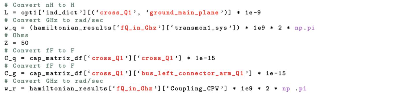
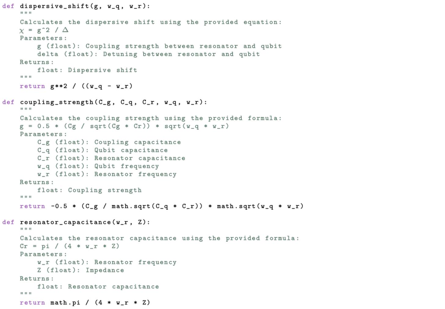
Wecanalsomodelthee↵ectivecapacitanceoftheCPW,denotedas Cr ,which characterizestheCPW’sabilitytostoreelectricalenergy.Additionally,wemodel thecouplingstrengthbetweentheresonatorandthetransmon, gq,r ,whichdefines theinteractionratebetweenthetransmonandtheCPW.Finally,weconsiderthe dispersiveshift,alsodenotedas �q,r ,whichdescribesthefrequencyshiftoftheresonatorduetothepresenceofthetransmon,asdiscussedinSection2.2.Thisshift enablesquantumnon-demolitionmeasurementthroughthereadoutCPW’sfrequency response,asdescribedin[92].Tomodel Cr , gq,r ,and �q,r wewillusethehamiltonian resultsandcapacitancematrixfromtheLOManalysisasshowninFig.3.17.The operationsdefinedinthisclassisshowninFig.3.18.
Figure3.17:Variablestouseintheequations.
Figure3.18:Pythonfunctionsforcalculating �q,r , gq,r ,and Cr
Notethatitisessentialtoperformunitconversionsduringtheparameterextractionstoensuretheconsistencyofthecalculations.Forinstance,inductancesare convertedfromnanohenries(nH)tohenries(H)bymultiplyingby1 ⇥ 10 9 .Frequenciesgiveningigahertz(GHz)areconvertedtoradianspersecondbymultiplyingby 2⇡ ⇥ 109 ,andsimilarly,frequenciesinmegahertz(MHz)areconvertedtoradiansper secondbymultiplyingby2⇡ ⇥ 106 .Capacitancesoriginallyinfemtofarads(fF)are convertedtofarads(F)bymultiplyingby1 ⇥ 10 15 .Theseconversionsarecrucial becausetheoperationsassumeSIunits.
3.5 AnalysisResults
Totesttheaccuracyoftheanalysisprocedure,wehavecomparedtheanalytical resultswithexperimentalresultsforapre-characterizedchiphostingsixtransmon
Q1,Q2,Q3,Q4,Q5,andQ6coupledtoreadoutresonators.Thepre-characterized chiphastheparametersshowninTable3.1.
Table3.1:Measuredparametersforsixtransmons,includingROfrequencies,coupling rates,qubitfrequencies,andanharmonicities.
Foreachofthesixtransmons,theinductanceoftheJosephsonjunctioniscalculatedbydeterminingthecriticalcurrent, Ic ,basedonthejunction’slength,width, andthecriticalcurrentdensity:
Similarly,thecapacitancecanbedeterminedusingtheJosephsonjunction’scapacitance.With Lj and Cj ,thesevaluescanbeincludedintheLOMdictionary foreachofthesix TransmonCross devices,asissimilarlydoneinFig.3.14.The dimensionsofeachpre-characterized TransmonCross ismeasuredfromachiplayout visualizationknownasKLayout.Withthedimensionlisted,wecanreconstructeach pre-characterized TransmonCross inQiskitMetaltofindeachtransmon’scapacitance matrix.
Thereportedvaluesofthetransmonfrequency,anharmonicity,andanotherimportantfromTable3.1isplottedwiththeanalyticalresultsoftheLOManalysisin Fig.3.19-3.21.
Figure3.19:Experimental(red)vsanalytical(blue)transmonfrequencyresultsfor apre-characterizedquantumprocessorhostingsixtransmons Q1, Q2, Q3, Q4, Q5, Q6.
Theaverageconstanto↵setbetweentheexperimentalandtheoreticalresultsin thetransmonfrequencyis0.319GHzleadingtoapercenterrorbetween8.44%and 5.26%asshownbyFigure3.19.
Theaverageconstanto↵setbetweentheexperimentalandtheoreticalresultsin thetransmonanharmonicityis-15MHzwithapercenterrorbetween10.74%and 8.44%asshownbyFigure3.20.
Theaverageconstanto↵setbetweentheexperimentalandtheoreticalresultsin thetransmonanharmonicityis-15MHzwithapercenterrorbetween13.16%and 3.31%asshownbyFigure3.21.
Figure3.20:Experimental(red)vsanalytical(blue)trasmonanharmonicitiesresults forapre-characterizedquantumprocessorhostingsixtransmons Q1, Q2, Q3, Q4, Q5, Q6
Figure3.21:Experimental(red)vsanalytical(blue)trasmonanotherimportantresultsforapre-characterizedquantumprocessorhostingsixtransmons Q1, Q2, Q3, Q4, Q5, Q6.
3.6 DeviceCircuitDesign Inthissectionwedescribethephysicalimplementationofthedualrailquantum processorincludingdetailsofhowthechosencircuitparameterswererealizedonthe physicalchip.
3.6.1
Layout AmicrographofthedeviceisshowninFig.3.22.Thedevicecontainssixtransmonresonatorpairs(blue).Fourofthesepairsareusedtocreatetwoplanardual-rails, whiletheremainingtwotransmon-resonatorpairsusedfortransmonstatereadout. ThereadoutresonatorsarecapacitivelycoupledtoindependentPurcellfilters(green). TheresultingstandingwaveinthePurcellfilterisusedasafilterresonance.
Figure3.22:Micrographofthedevice.Thefalsecolorsrepresenttheelementsof thelumpedelementmodel,asshowninthetoprightinset.Signalsenterthesystem througheitherofthetwofeedlines(black).ThePurcellfilter(green)isa � 2 standing waveresonator,openatbothends,andisstronglycoupledtothefeedline,withan impedancemismatchbetweenthemactingasafilteringstep.ThisPurcellfilteris weaklycoupledtothereadoutresonator(blue),whichisinturncoupledtothequbit (red).Signalsinjectedintothefeedlinearemostlyreflectedattheweaklycoupled interfacebetweenthePurcellfilterandthereadoutresonator.Thetransmittedenergythatreachesthereadoutresonatorexcitesitsresonance,whichinteractswith thequbit.Theresultingmodulatedsignal,influencedbythequbitstate,isthen transmittedbackthroughthePurcellfilterandexitsthroughthesamefeedline.The redarrowindicatesthepathbywhichenergyleavesthefilterthroughawirebond (notshown)andenterstheexternaldetectionhardware,includingaparametricand HEMTamplifier.ThisS(2,1)measurementenablesthereadoutofthequbitstateby analyzingchangesinthetransmittedsignal’samplitudeandphase.
3.6.2 PurcellFilter ThePurcellfilterisimplementedasa �/2CPWresonator.Thevoltageantinodes areformedatthelocationoftheinterdigitalcapacitorswherethefilterconnectswith thefeedlineandthereadoutresonator.
Impedance Thecharacteristicimpedanceofthefilterisrelatedtothedesiredimpedanceby
where ✏e↵ =(1+ ✏s )/2isthee↵ectivedielectricconstant, ✏r istherelativedielectric constant, h isthedielectricthicknessofthechip, a iswidthoftheconductor,and b isthesumoftheconductorwidthandthegapineithersidesasshownFig.3.23.In ourexperimentweusedsiliconsubstratewith ✏r =11.45,dielectricthicknessof350 microns,conductorwidthof10microns,sumofconductorwidthandgapateither sidesof26micronsgivingacharacteristicimpedanceof50ohms.
Figure3.23:Cross-sectionofaCPWresonatorshowingE-fielddistribution(V/m)at a318.8phase.
Feedline-PurcellFilter:Combcoupler
Theinputcapacitance Cin controlsthecouplingbetweenthefeedlineandthePurcell filter,ensuringe�cientenergytransferwithoutoverloadingthereadoutresonator. Thisdesignintroducesanintentionalimpedancemismatch,withPort1andPort2 havinganimpedanceof89.5 ⌦ and85.5 ⌦ respectively,asshowninFig.3.24.The S-parametershowsreflectionintheS12measurementcharacteristicofanimpedance mismatchasshowinFig.3.25.
Themismatchcreatesahigh-impedanceenvironmentthatoptimizessignaltransmissionbyincreasingthedesiredreflectionsattheresonantfrequenciesofthePurcell filterandthereadoutresonator,whilesimultaneouslyminimizingunwantedreflectionsatotherfrequencies.Byengineeringthisimpedance,wecanenhancestheinteractionbetweenthefilterandtheresonator,ensuringmoree�cientenergytransfer andreducingphotondissipationintotheoutputcircuitry.
Figure3.24:DiagramoftheinterdigitalcapacitordesignbetweenthePurcellfilter andthefeedline,labeledwithPort1andPort2,alongwiththecorresponding Z0 impedanceplot.Theimpedanceplotshowstherealpartoftheimpedanceatboth portsacrossafrequencyrangeof1to10GHz.Port1exhibitsanimpedanceof approximately89.5ohms,whilePort2showsanimpedanceofabout85.5ohms,both deviatingsignificantlyfromthestandard50-ohmcharacteristicimpedance.Thisintentionalimpedancemismatchenhancestheresonator-filtercouplingbycreatinga high-impedanceenvironmentthatoptimizessignaltransmissionandminimizesunwantedreflectionsattheoperationalfrequencies.
Figure3.25:S-parameterplotshowingthereflectionandtransmissioncharacteristics oftheinterdigitalcapacitordesignintheresonator-filtercouplingsystem.Theplot includesthereturnloss(S (1, 1)and S (2, 2))andtransmissioncoe�cients(S (1, 2)and S (2, 1))betweenPorts1and2,demonstratingthefrequency-dependentbehaviorof thesystemandthee↵ectivenessoftheimpedancemismatchinachievingthedesired coupling.
3.6.3 ReadoutResonators Thereadoutresonators,likethePurcellfilter,wereimplementedas �/2CPWresonatorwithcharacteristicimpedanceof50 ⌦.Inthissectionweexplainhowwe designedthecouplingbetweenthemeasurementresonatorsandtransmonandbetweenthemeasurementresonatorsandthePurcellfilter.
Readout-Transmonresonatorcoupling:clawcoupler Thereadoutresonatorwerecapacitivelycoupledtothequbits.Weusedinterdigitalcapacitorsnicknamed“claw”capacitor.Theclawcapacitornotonlycouplesthe resonatortothetransmon,butalsoformsalargecapacitancetoground.Thiscapacitancetogroundchangestheresonator’se↵ectivelengthrequiringANSYSHFSS analysistoextractthereadoutresonator’sresonantfrequenciesasshowninSection 3.3.3.Tofacilitatethedispersiveshiftinteractionwithstrongcouplingbetweenthe
qubitandreadoutresonator � = g 2 /�,thecouplingstrength g wasengineeringtobe relativelyhighat146MHzbymakingthe claw width =43microns, claw length = 91microns,and claw gap =6microns.
Readout-PurcellFilter:fingercoupler ThecapacitivecouplingbetweenthereadoutresonatorandthePurcellfilterwasimplementedusinginterdigitalcapacitorswithseveralfingersnicknamednicknamed “finger”.AsshowninFig.3.2,theparametersfor finger length, cap width, cap gap,and finger number wereadjustedtogetthedesiredcouplingcapacitance. ThiscapacitancewasextracteddoingANSYSQ3DasshowninSection3.4.2.
3.6.4 Dual-Rail Thedual-railresonators,likethePurcellfilterandthereadoutresonators,wereimplementedas �/2CPWresonatorwithcharacteristicimpedanceof50 ⌦.Inthis sectionweexplainhowwedesignedthecouplingbetweenthepairofCPW,between theCPWandthetransmon,andbetweentheCPWandthecoupler.
Dual-Rail1 The �/2CPWresonatorwerecapacitivelycoupledtothetransmomusingtheclaw capacitorasitissimilarlydoneinthereadout-transmoncapacitor.Toensurethe dispersiveregimewithweakcouplingbetweenthetransmonandtheresonatorrequiredforthecreationandmanipulationofbosonicgates,thecouplingstrength g is relativelylowat33.71MHzcomplementedwitharelativehighfrequencydetuningof 1.5GHz.Thecapacitordimensionare claw width =13.3microns, claw length = 140micronsmicrons,and claw gap =6microns.Inourdeviceweused !r =6.327 GHzforeachofthetwoCPWmakingupthedual-rail.
ThecouplingbetweentheCPWisdependentontheamountofhybridizationwe
wanttoinduce.WeobservedinFig.3.9thehybridizationoftworesonantmodesof adual-rail.Thishybridizationisdependentonthecapacitancecouplinginducedby thefingercapacitorbetweenthetwoCPW.Inthisdesign,wehavereplicatedthis capacitancecoupling Cg =18.5fFusing finger count =5, finger length =40 microns,and cap gap =2microns.Ahigherhybridizationcanbeengineeredby increasing Cg withthedimensionavailableinthedictionaryofthefingercapacitor inMetal.
Dual-Rail2 Theseconddual-railinthechipfollowsthesamedesignprocedureasthefirstdual-rail withafrequencydi↵erenceof1.5GHz.
3.6.5 Transmons ThetransmonsmadeofAluminiumisfabricatedonasiliconchipalongwithareadoutresonatorandaPurcellfilter.Thepurposeofthetransmonsinthedual-rail quantumprocessoristwo-fold:topreparequantumstatesinthethebosonicmodes viaauxiliarytransmonsandtoinducephotoninteractionbetweenthebosonicmodes viaasuperconductivenonlinearasymetricinductiveelement(SNAIL).
AuxiliaryTransmons Bymeasuringthedispersiveinteractionbetweenthedual-railandtheauxiliarytransmon,statepreparationandjoint-Wignertomographycanbeperformed.Todothis, itisimportanttomaintainaweaklycoupleddispersiveinteractiontothebosonic modestominimizedecoherenceintheCPWresonator.Thisisachievedbytherelativehighdetuningof1.5GHzandlowcouplingstrengthof33.71MHz.Inourdevice weused Lj =8.23nH, !q /2⇡ =4.681GHz,and ↵ =-251MHzfortheauxiliary transmonforDual-Rail1and Lj =5.30nH, !q /2⇡ =6.181GHz,and ↵ =-251MHz
fortheauxiliarytransmonforDual-Rail2.
Tobeabletotunethefrequencyoftheauxiliarytransmon,wehavemadefluxtunabletransmonscomprisetwoJosephsonjunctionsinaSQUIDloopinparallel withtheshuntingcapacitorbuiltby TransmonCross inMetal.Thisisdonebyfirst determiningtheareaoftheJosephsonjunctionforeachdual-railgivenby Lj ,critical currentdensity,Josephsonjunctionwidth,andJosephsonjunctionlengthasdiscussed inSection3.5.TheareaoftheoriginalsingleJosephsonjunctionisdividedbytwo andsharedareaequallywithtwoJosephsonJunctionsinaSQUIDloop.Wecan controlthee↵ectiveJosephsonenergy EJ oftheSQUID,andthereforethetransitionfrequencybetweenthegroundandthefirst-excitedstateofthetransmon,by threadingmagneticfluxthroughtheSQUIDasshowninFig.3.26.
Figure3.26:Flux-tunabletransmoncomprisedoftwoJosephsonjunctioninparallel withashuntingcapacitortotheleft.Themagneticfluxisthreadedandinducedby sendingcurrentinthefluxlinetotherightoftheJosephsonjunctions.Aslotlineis addedbetweenthefluxlineandtheflux-tunabletransmontoprotectthetransmon frompotentialexeternalnoiseresources.
Thefrequencyofthetransmoninresponsetoanappliedexternalflux �ext is approximatelygivenby[89]:
where EC isthetransmonchargingenergyand f max = �p8E
EC � /h is themaximumqubitfrequency.Theasymmetryparameter d oftheSQUIDjunctions isgivenby d = |
,where EJ,1 and EJ,2 aretheJosephsonenergiesofthe twoSQUIDjunctions.Theaboveequationisshownwithrespecttofrequencyand normalizedmagneticfluxoftheauxiliaryqubitofdual-rail2inFig.3.27.Notethat theequationisanapproximationbecauseitholdsonlyinthelimit EJ � EC inthe
transmonwedesigned.
Figure3.27:Qubittransitionfrequency fqubit asafunctionofnormalizedmagnetic flux �/�0 foradual-railtransmon.Thecolorscaleindicatestheasymmetrybetween thetwoJosephsonjunctionsintheSQUIDloop.
Inordertodrivethetransmon,adrivelineisweaklycoupledforeachofthetwo auxiliary.Theoptimalcouplingcapacitancebetweenadrivelineandatransmonto reduceenergylossmechanisminducebytheenvironmentcouplinghasbeenfoundto be0.1fF[91].UsingthecapacitanceextractioninSection3.4.2,wecanengineera linecouplerusing claw type =1inMetalsuchthatthecouplingcapacitancematches 0.1fFasshowninFig.3.28.
Figure3.28:Capacitancematrixbetweenthedriveline bus left connector arm Q1, thetransmon cross Q1,andground ground main plane.Thecapacitancebetween thedrivelineandtransmon(redbox)isengineeredtobe0.1fF.
CouplerTransmon:SNAIL TheSNAIL(SuperconductingNonlinearAsymmetricInductiveeLement)consistsof asuperconductingloopwith n largeJosephsonjunctionsandasinglesmallerjunction. Theproposedcircuithastheinductiveenergy:
where ' isthesuperconductingphaseacrossthesmalljunction, � istheasymmetrybetweenthelargeJosephsonjunctionsandthesmallerjunction, 'ext =2⇡ �ext /�0 isthereducedappliedmagneticflux,and �0 = h/2e isthemagneticfluxquantum. NotethatEq.3.9isonlyafunctionofasingledegreeoffreedom ' asweeliminated thedynamicsduetoanyintra-arraymodesandconsideredonlycommonexcitations acrossthearrayof n junctions.Thisreductionisvalidwhen EJ � EC foreach junctionwhere EC = e2 /2CJ istheCoulombchargingenergyofthejunctionwith capacitance CJ .Wewillassumeinthefollowingthattheseconditionsarerealized. ThroughnumericalminimizationofEq.3.9,weanalyzetheSNAIL’smixing
capabilitiesbyTaylorexpandingabouttheminimum 'min toobtainthee↵ective potentialfor˜ ' = ' 'min :
where(c2 ,c3 ,c4 , ··· )arenumericallydeterminablecoe�cientswhosespecificvaluesdependon n, ↵,and �ext .Toachieveapurecubicnonlinearitywithoutany Kerre↵ect,weaimforapotentialwithanonzero c3 ,whilesetting c4 =0,e↵ectively eliminatingthequartic(Kerr)term.
Thecoe�cients c3 and c4 canbecalculatedbydi↵erentiatingtheSNAILpotential withrespectto ',andsincethepotentialdependson � ,thevaluesof c3 and c4 change as � changes.Wecanthereforefindacombinationof � and �ext �0 tominimizethe quarticterm c4 asshowninFig.3.29.
Figure3.29:Heatmapsofthecubic(c3 )andquartic(c4 )nonlinearcoe�cients, obtainedviasymbolicdi↵erentiationoftheSNAILpotential,asfunctionsofthe reducedexternalflux �ext /�0 andtheratio � betweenthelargeandsmallJosephson junctionenergies.Theblackcrossesmarkthechosenwhere c3 isnonzeroand c4 is closetozero,indicatingminimalKerrnonlinearity.
Inourdevice,weused Lj =5.30, !c =5 250, ↵ =-149,and � =0.29withaflux linecoupledtotheSNAILasshowninFig.3.30.
Figure3.30:Flux-tunableSNAILcomprisedofthreelargeJosephsonjunctionand asinglesmallerjunctionwithashuntingcapacitortotheleft.Themagneticfluxis threadedandinducedbyacurrentcominginfromthefluxlinetotheright.
Thedispersiveshiftsbetween Dual-Rail1 andtheSNAIL,andbetween Dual-Rail 2 andtheSNAIL,arematchedtoachievecross-Kerrmatchingfore↵ectivejoint Wignertomographyonthetwo-modeHilbertspace.
3.6.6 DeviceCircuitParameters FromouranalysisofthetransmonandCPW,wehaveengineeredtheparametersfor eachcomponentinourdevice(Table3.2andTable3.3).Thetransmon-resonator couplingstrength g isdeterminedseparatelydependingonwhetherthecouplingis betweenatransmonandareadoutresonatororatransmonandadual-rail.Each transmoniscanbedrivenandisflux-tunable.
L j [nH] ! q / 2 ⇡ [GHz] ↵ [MHz] ! r / 2 ⇡ [GHz] � / 2 ⇡ [kHz] g q,d / 2 ⇡ [MHz] C q [fF] C g,drive [fF]
Transmon18.234.681-2516.327-516.5933.7186.640.10
Transmon25.296.181-2517.828-517.2933.7085.750.10
Coupler5.305.250-1496.327,7.828-2124,-212088.49,264.98139.960.93
Table3.2:Circuitdesignparametersfortheauxiliarytransmonfordual-rail1 Transmon1 ,auxiliarytransmonfor dual-rail2 Transmon2 ,andcouplertransmonbetweendual-rail1anddual-rail2 Coupler
Mode ! r / 2 ⇡ [GHz]
Dual-Rail1Mode16.216(6.327)
Dual-Rail1Mode26.437(6.327)
Dual-Rail2Mode17.716(7.828)
Dual-Rail2Mode27.937(7.828)
Table3.3:Hybridizedmodesof thepairofdual-rails,withnon- hybridrizedmodesofdual-railcavity qubitsshowninparentheses.
3.7 Fabrication ThedeviceisbeingfabricatedbyMITLincolnLaboratoryusingthin-filmaluminum onasiliconsubstrate.ThewiringcrossoversandJosephsonjunctionsaremadefrom anAl/AlOx /Altri-layer.Thefabricationprocessincludesthefollowingsteps:
1. Definingcontrollinesandresonators:
(a) Aluminumfilm,approximately100nmthick,wasdepositedona3-inch siliconwaferusingelectronbeamevaporation.
(b) Driveandfluxlineswerepatternedviaopticallithographyandetchedwith aninductivelycoupledplasma(ICP)usingBCl3 /Cl2
2. Etchingthetransmonqubit:
(a) Thecrossshapeofthetransmonqubitwasetchedintothealuminumlayer usingthesameprocessasforthecontrollinesandresonators,separated tominimizeprocessingstepsandpotentialdamagetoqubitfeatures.
3. Alignmentmarkpatterning:
(a) Goldalignmentmarkswereformedusingelectronbeamevaporatedgold throughalift-o↵ processtoaligntheelectronbeampatternwiththeopticalpatternsforthesubsequentstepinJosephsonjunctionformation accurately.
4. Josephsonjunctionformation:
(a) Josephsonjunctionswerefabricatedusingdouble-angleshadowmaskevaporationinthePlassyschamber.Theshadowmaskwasdefinedviaelectron beamlithography,with insitu ionmillingofthebaselayertoremovenativeoxidebeforedeposition.
4 Inthepastdecade,QuantumToolboxinPython(QuTiP)hasevolvedintooneofthe leadingopen-sourcequantumsimulatorsforquantumprocessors.Whileotheropensourcequantumprocessorssimulatorsareavailable,QuTiPisthesimulatorwiththe mostextensivetutorialsavailable[95].Inthiswork,wewilluseQuTiPtosimulatethe non-drivenanddrivenevolutionofthetransmonsinthedual-railquantumprocessors.
QuantumSimulation AlongwithQuTiP,theuseofBosonicQiskitwillenableustocreate,simulate,and studyhigh-levelsingle-andmulti-qumodegatesandphase-spacevisualizationthat canbepeformedinthedual-railquantumprocessor.Inthiswork,wewilluseBosonic Qiskittosimulateevenandoddcatstates,+ZGKPcodeword,andbeam-splitter interactionbetweenbosonicmodes.
4.1 QuTiP ThecoreQuTiPpackageisthemainmodulethatprovidestheenvironmentforcarryingoutmostquantumsimulations.QuTiP,inessence,isbasedonaquantumobject classcalled Qobj,whichenablestherepresentationofquantumoperatorsandbra/ket vectors.Earlier,wediscussedthestatevectors |0i and |1i asthebasisstatesoftransmons.Thesestatesarealsoreferredtoasket-vectors,orsimplykets.Everykethasa correspondingHermitianconjugate,whichisitselfavector,calledabra-vector.For instance,thebraof |1i isgivenby:
Diracnotation,commonlyusedtorepresentquantumstates,iswell-suitedfor expressingtheinnerandtensorproductsinvolvedinquantummechanics.QuTiP simplifiestheconstructionofthesestatesbyallowinguserstoeasilyrepresentkets andbraswiththe Qobj class.Forexample,constructingthequbitstate |1i canbe doneusingacorresponding Qobj,asshowninFig.4.1.QuTiPalsoprovidesbuilt-in
functions,suchas basis,togeneratethesestatesdirectly[ref].
|1i asa Qobj inQuTiP
Whendealingwithqubit-qumodesystems,weextendbeyondthefinitequbit spacetoincorporatetheinfinite-dimensionalHilbertspaceofqumodes.Aqumode, representedbyFockstates |ni,canhostaninfinitenumberofstates,makingitdistinct fromaqubit’stwo-statesystem.Forinstance,ifwecombineaqubitinstate |0i and aqumodeintheFockstate |ni,theirtensorproductisrepresentedas:
InQuTiP,thecreationofqumodescomesmustcomewithacuto↵ dimension thattruncatestheitsinfinite-dimensionalHilbertspace.Thechoiceofcuto↵ dimensioncanberefinedbygraduallyincreasingituntilasteadysimulationisachieved. ThisishighlydependentonthestatesandinteractionsconsideredinthecompositeHamiltonian.BecauseBosonicQiskitisspecificallydesignedtohandlequmodes moree�ciently,wewilluseQuTiPtosimulatethedynamicsofonlttheauxiliary transmonsinthedual-railquantumprocessor.
4.1.1 Non-DrivenEvolutionwith mesolve
WewillbeginthesimulationofdualrailquantumprocessorbyevolvingthetimeindependentHamiltonianofthedevice.Todothis,wemustdefinetheFockstate
Figure4.1:Constructing
operators,sowecanplottheexpectedenergylevelasafunctionoftime.Thenumber operatorisdefinedastheproductoftheraisingandloweringoperator.FortheQuTiP code,wewillbelabeling transmon 1 fordual-rail1auxiliarytransmon, transmon 2 fordual-rail2auxiliarytransmon, transmon 3 forthecoupler, cavity 11 forthe firstfundamentalresonantmodeofdual-rail1, cavity 12 forthesecondfundamental resonantmodeofdual-rail1, cavity 21 forthefirstfundamentalresonantmodeof dual-rail2,and cavity 22 forthesecondfundamentalresonantmodeofdual-rail2.
Theintrinsictime-independentHamiltonianisgiventheJaynes-CummingHamiltonianfromEq.2.31:
areapproximated fromTable3.2and3.3and ˆ bi (†) istheannihilation(creation)operatorforauxiliary transmoniwherei=1,2andˆ ajk (†) istheannihilation(creation)operatorforthe dual-railjmodekwherej,k=1,2.
Becausetheraisingoperatorissimplytheconjugatetransposeofthelowering operator,wewillfocusonconstructingtheloweringoperatorfirstandthenwillsimply callthe dag methodofthe Qobj toconstructtheraisingoperator.Wemustconstruct eachoperatorsoithascompatibledimensionswiththecompositeHamiltonian.We willbeusingthecuto↵ dimensionsof2for transmon 1, transmon 2, transmon 3 and 4for cavity 11, cavity 12, cavity 21, cavity 22 asshowninFig.4.2Ideally,we wanthighercuto↵ dimensionfortheCPWresonatorbutsincewearefocusingon drivenandnon-driveevolutionoftheHamiltonian,wedonotneedtoworryhigher levelexcitations.
Figure4.2:LoweringandFockstateoperatorconstructions.
Notethatweusethe qeye function,whichreturnsan N ⇥ N identitymatrix,where Nistheinputdimension.Usingthisfunctionwillallowustocomposetheoperators withthecorrectdimensions.Additionally,wewillusethe destroy functionwhich constructstheloweringoperatorwithinputdimensionsN.
Withthecreationoftheloweringoperatorsandnumberoperators,weareableto definedtheHamiltonianfromEq.3.3inQuTiPgivenby
Figure4.3:LoweringandFockstateoperatorconstructions.
Next,wewilldefinetheinitialstatesofeachsubsystem,byusingthe basis function.Wewillinitiallyset Transmon 1 and Transmon 2 intheexcitedstateand therestofthesysteminthegroundstate.Weaccomplishthisbytakingthetensor productoftheirstatestoconstructthestatevectorofthesystemgivenby Figure4.4:Initialstatevectorconstructionwithauxiliarytransmonsintheexcited state.
WecannowpasstheinitialstatevectordefinedandtheintrinsicHamiltonian alongwiththetimestepofthesimulation tlist to mesolve toevolvethesystem withtheSchr¨odingerequationasshowninFig.4.5.Inthissimulation,weconstruct tlist rangingfrom0to250nswith1000incrementsincrementstoensurethereis adequatetimetocapturethesystem’stimeevolution.
Figure4.5:Evolvesystemwith mesolve.Notethatsincethecollapseoperatorlist c ops isempty,the mesolve usestheSchrodingerequation
Notetherangeandincrementsoftlistmayneedtobealteredtodependingon thedurationofthesystemstimeevolution.Additionally,notethat mesolve havea parametercalledOptionsusedtocustomizethesolver’sbehavior.Inthissimulation, wedefinetheoptiontonotstorethequantumstateateachtimestep, store states, tobe False.Theusercanset store states to True toextractthequantumstateof eachtransmonateachtimestepandobservehowthetransmonrevolvesintimein aBlochSphere.Theparametercopsrepresentsthelistofcollapseoperators,which areusedtomodeldissipationanddecoherenceinthesystem.Inthissimulation,
however,weassumeaperfectlylosslesssystem,sonocollapseoperatorsareincluded. Theparameter e ops isthelistofexpectationoperatorsbeingtrackedduringthe simulation.
Nowthatwehaveevolvedthesystem,wewillusethe result todisplaythe expectationvalueoftheoccupiedstate,oroccupationprobability,ofeachauxiliary transmonanddual-railmodes.Tofindtheexpectationvalue,weusethe expect functionwheretheindexnumberassociatedwitheachtransmonanddual-railmode isbasedontheorderingin e ops inFig.4.5.Notethatthefirstelementinthelist isindex0,soqubit1isassociatedwith result.expect[0].
Figure4.6:Calculatingoccupationprobability.
Wecanthenplotaquasi-occupationprobabilityusing matplotlib asshownin
Fig.4.7
Inthisplot,weobserveboth Transmon1 and Transmon2 intheexcitedstate withapopulationprobabilityrangingbetween99.88%and99.99%.Thereasonwhy thepopulationprobabilitiesoftheauxiliarytransmonsarenot100%isduetoweak crosstalkwiththedual-rails.AsdiscussedinSection [weaklycoupling],thedualrailsandauxiliarytransmonsareinthedispersiveregimewithweakcoupling.This weakcouplinginducesasmallamountofcrosstalkbetweenthem.
Animportantpointtonoteisthat Dual-Rail2Mode1 and Dual-Rail1Mode 2 experiencethesameamplitudeofcrosstalkbecausetheirdetuningwiththeirrespectiveauxiliarytransmonisidentical.Asimilarsituationoccurswith Dual-Rail2 Mode2 and Dual-Rail1Mode1,wheretheircrosstalkamplitudeislowerthantheir counterpartsduetohavinggreaterdetuningwiththeirauxiliarytransmon.Thissim-
Figure4.7:Occupationprobabilityof Transmon1, Transmon2, Cavity1Mode1, Cavity1Mode2, Cavity2Mode1,and Cavity2Mode2 with Transmon1 and Transmon2 initiallyintheexcitedstateandtherestofthesystemintheground state.
ulationshowsthatdespiteengineeringtwodi↵erentdual-railswithdistinctresonant frequencies,theircrosstalkamplitudecanbethesamewhenthecouplingstrength anddetuningbetweentheauxiliarytransmonandthedual-railsarethesame,asour parametersshowinTable3.3andTable3.4.
4.1.2 DrivenEvolutionwith mesolve
Inthissection,wewilldiscussthedrivenevolutionofthedual-railquantumprocessor byconsideringthedriveslinesofeachauxiliarytransmon.TheHamiltonianofthe simulationissimilartoEq.4.3withanadditionaldrivingtermrepresentingthe drivingmicrowavesignalappliedoneitherauxiliarytransmon.
ThedriveHamiltonian ˆ HDrive canbedecomposedintotimeindependentoperator ˆ HDriveTI andtimedependentscalar ˆ HDriveTD :
where ⌦ isthedriveamplitudeinVolts, !q istheresonantfrequencyofthetransmonbeingdriven,ˆ a† q andˆ aq aretheraisingandloweringoperatorsofthetransmon beingdriven,and � istheinitialphasegiventothedrivesignal.
Next,wewillconstructafunctionfor ˆ HDriveTI whichwilldefinewhichqubitwill bedrivenandtheamplitudeofthedrivesignal.Theprocessisstraightforward,and wewilltakeadvantageoftheoperatordictionariesweconstructed.Thecodeto constructthe H driveTI and H driveTD functionsisgivenby
Figure4.8: H driveTI and H driveTD functions.
This H driveTI functiontakestwoarguments, amp whichisanumberthatrepresents ⌦ in(4.3)and lower op whichrepresentsthekeyfortheloweringoperator dictionary A anddefineswhichqubitwillbedriven.Thetime-dependentHamiltonianisconstructedinasimilarlystraightforwardmannerwhere t isanarrayof evenlyspacedtimeintervalswhichthesolverwillpass, w istheresonancefrequency ofthetransmontobedriveninGrads/s,and � isthephaseshiftimposedonthe drivesignal.Notethatwewillnotpass w and � tothefunctionandmustdefine theseBeamsplitterinteractionsselsewhere.Wewillpassthefunctionwithoutcalling
ittothefullHamiltonian,whichwillallow mesolve topassthesamelistoftimesto thefunctionwhenthesolveriscalled.
Nowwewilldefine amp, � and lower op.WewillinitiallydefinetheseBeam splitterinteractionssasshowninFig.4.9.WewillthenconstructtheHamiltonian byconstructinganew Qobj asshowninFig.4.10whereweusedtheannihilation operatorsdefinedduringthenon-drivenevolutionoftheHamiltonian.
Figure4.9:BeamsplitterinteractionsdefinitionforthedrivingHamiltonian ˆ HDrive
Figure4.10: ˆ HDrive function.
Finally,wewillrunthesimulationinthesamefashionasinSection4.1.1andwill setallinitialstatestothegroundstate.TheresultisaRabioscillationin Transmon 1 and Transmon2 state.
Figure4.11:Occupationprobabilityof Transmon1, Transmon2, Cavity1Mode1, Cavity1Mode2, Cavity2Mode1,and Cavity2Mode2 with Transmon1 and Transmon2 initiallyintheexcitedstateandtherestofthesystemintheground state.
4.2 BosonicQiskit BosonicQiskitisanextensionofthecoreQiskitframeworkdesignedtosimulatequbitresonatorsystemsconsistingofbothqubitsandqumodes.InBosonicQiskit,qumodes arerepresentedascontinuous-variablesystems,whilequbitsremaindiscrete-variable systems.UnlikeQuTiP,whichisbuiltaroundthe Qobj classforrepresentingquantum states,BosonicQiskitreliesonQiskit’s QuantumCircuit structure,enhancedthrough the CVCircuit classthatintegratesqumodesviathe QumodeRegister.Thisallow userswhoarealreaydfamiliriazedwithQiskittoconstructandmanipulatequbitqumodesystems.
BosonicQiskitalsoallowstheapplicationofvariousqubit-controlledgatesand operationsonqumodes,enablinghybridquantumalgorithms.Onecommonexample isthepreparationofcatstates,whereaqubitandqumodeareentangledthrough
conditionaldisplacementoperations.Thesystem’sevolutionissimulatedusingbuiltinfunctions,andresultslikeWignerfunctionscanbevisualizeddirectly.Thechoice ofcuto↵ dimensionforqumodesisacrucialparameterinthesimulationsbecause itdefinesthemaximumnumberofenergylevelsconsideredforeachmode,directly impactingtheprecisionandconvergenceoftheresults.
4.2.1 VacuumStatePreparation Toinitializethevacuumstate,weusethe cv initialize functionfromthe c2qa library.Thisfunctionsetsthequmodetothezero-photonFockstate,denotedby |0i,whichcorrespondstothevacuumstateinquantumoptics.Thevacuumstateis mathematicallydescribedas:
whereˆ a istheannihilationoperator.Thismeansthatapplyingtheannihilation operatortothevacuumstateleavesitunchanged,confirmingtheabsenceofphotons.
Intheexamplebelow,asinglequmodeispreparedinthisstateusingacircuitthat combinesaqubitregister(QuantumRegister)andaqumoderegister(QumodeRegister).
Figure4.12:BosonicQiskitcodeforgeneratingazero-photonFockstate.
Theresultingstatevectorcorrespondstothequmodeinthezero-photonstate |0i, whichisconfirmedbytheoutputshowingthevacuumstatewithnocontribution fromhigherphotonnumberstates(suchas |1i, |2i,etc.):
Statevector([1.+0.j,0.+0.j,0.+0.j,0.+0.j,0.+0.j,0.+0.j,0.+0.j,
0.+0.j,0.+0.j,0.+0.j,0.+0.j,0.+0.j,0.+0.j,0.+0.j, 0.+0.j,0.+0.j,0.+0.j,0.+0.j,0.+0.j,0.+0.j,0.+0.j, 0.+0.j,0.+0.j,0.+0.j,0.+0.j,0.+0.j,0.+0.j,0.+0.j, 0.+0.j,0.+0.j,0.+0.j,0.+0.j,0.+0.j,0.+0.j,0.+0.j, 0.+0.j,0.+0.j,0.+0.j,0.+0.j,0.+0.j,0.+0.j,0.+0.j, 0.+0.j,0.+0.j,0.+0.j,0.+0.j,0.+0.j,0.+0.j,0.+0.j, 0.+0.j,0.+0.j,0.+0.j,0.+0.j,0.+0.j,0.+0.j,0.+0.j, 0.+0.j,0.+0.j,0.+0.j,0.+0.j,0.+0.j,0.+0.j,0.+0.j, 0.+0.j,0.+0.j,0.+0.j,0.+0.j,0.+0.j,0.+0.j,0.+0.j], dims=(2,2,2,2,2,2))
TomographicVisualization Tobetterunderstandthecharacteristicofthevacuumstate,wecansimulatethe Wignerstatetomographyofthedual-railstate.InordertoperformWignerstate tomography,Hamiltonianofaqumodeisreadilywrittendownintermsofthequadratureoperators ˆ X and ˆ P ,whichsatisfythecanonicalcommutationrelationship:
wherethequadratureoperators ˆ X and ˆ P aredefinedintermsoftheannihilation andcreationoperatorsˆ a andˆ a† asfollows:
Because ˆ X and ˆ P areconjugatevariables,theyrepresentthequantumanalogof positionandmomentuminphasespace.Thecommutationrelationshipreflectsthe factthatthesevariablescannotbemeasuredsimultaneouslywitharbitraryprecision, duetotheHeisenberguncertaintyprinciple.
Intermsofquadratureoperators,theHamiltonianforaqumodeisthengivenby:
where ! representsthefrequencyofthemode.ThisHamiltoniancloselyparallels thatofaclassicalharmonicoscillator,withthetotalenergybeingthesumof‘potential energy’(dependenton ˆ X )and‘kineticenergy’(dependenton ˆ P ).
Inthiscontext,wecantake ˆ X and ˆ P contributionstoconstructtheWigner function,apowerfulrepresentationofthequantumstatewithinphasespace.For agivenquantumstate ⇢ suchastheoutputfromFig.4.12,theWignerfunction
W (x,p)isdefinedas:
)=
where x and p denotepositionandmomentum,respectively.Inthecaseofthe vacuumstate |0i,theWignerfunctiontakestheformofaGaussiandistribution, centeredattheorigininbothposition X andmomentum P .
Thisindicatesthatthevacuumstateislocalizedinphasespacewithminimal uncertaintyinboth x and p,reflectingtheHeisenberguncertaintyprinciple.The code plot wigner(circuit0,state0) plotstheWignerfunctionofthequmode createdinFig.4.12,representingthevacuumstateinphasespace:
Figure4.13:2Dand3DWignerfunctionrepresentationofthevacuumstatewith respecttothequadraturesoperators ˆ X andmomentum ˆ P
Thetomographyofthevacuumstatecanbedepictedinboth2Dand3Dplots.The WignerfunctionshowsaGaussianpeakattheorigininphasespace,confirmingthat thequmodeisindeedinthevacuumstate.Theabsenceofnegativevaluesinthe Wignerdistributionfurthersupportstheclassical-likenatureofthevacuumstate,as non-classicalstates,suchassqueezedorcatstates,typicallyexhibitnegativeregions intheirWignerfunction.
Thecodedefinedcansimilarlybeinitializedinthesecondexcitedstatebysetting cv initialize(1,qmr0[0])).Thecode plot wigner(circuit0,state0) plots theWignerfunctionofthefirstexcitedstateasshowninFig.4.14.
Figure4.14:Firstexcitedlevelwithrespecttothequadraturesoperators ˆ X and momentum ˆ P .Thenegativityofthedistribution,aclearproofofthenon-classical characterofthestate,isevidentaroundtheorigin.
4.2.2 CodeWordsPreparation Wenowdemonstratetwoexamplecircuits:onetoprobabilisticallyprepareacatstate,andanothertopreparethe+Zfinite-energyGKPcodeword.Inbothcases, werequireasinglequmodeandasingleauxiliaryqubit.Wefirstdemonstratethe preparationofacatstategivenby:
where |± ↵i correspondstocoherentstatesofoppositephase, N isanormalization constant(whichdi↵ersfromtwoduetothefactthatcoherentstatesarenotexactly orthogonal),andtheparity(i.e.,therelativephase ±),isdeterminedbytheoutcome ofmeasuringtheauxiliaryqubit.
Theentirepreparationalgorithmcanbedescribedinthreesteps:
1. ApplyaHadamardtotheauxiliaryqubittopreparethestate |+i
2. Entanglethequmodeandauxiliaryqubitusingtheconditionaldisplacement
1. MeasuretheauxiliaryqubitintheX-basis(i.e.,byapplyingaHadamardand measuringintheZ-basis)
Below,wedemonstratethecodetopreparethecatstate:
Figure4.15:BosonicQiskitcodeforgeneratinganevencatstate.
TheWignerfunctionplotandcircuitdiagramofthecatstatearedisplayedin 4.15and4.16.
Inourdevice,eachgatewouldbeimplementedusingmicrowavesignalscoupled tothetransmonanddual-rail.Inordertoperformthefirststate,Hadamard,pulse calibrationandsequencesmustbeengineered.
Figure4.16:2Dand3DWignerfunctionrepresentationofanevencatstateinterms ofquadratures ˆ X and ˆ P .
Figure4.17:Quantumcircuittocreateanevencatstateillustratingacontrolled operationonaqubit-resonatorsystemwithaqumodcuto↵ dimensionof24 .
Asasecondexample,wewillnowdemonstrateacircuittopreparethe+Z(finiteenergy)GKPcodeword.Moreinformationaboutthegatesequencetopreparethis non-trivialstatecanbefoundin[93].Inshort,thisisachievedbylayering“echocontrolleddisplacements”whichcanbebrokendownascontrolled-displacementin thedual-railalongwithXgateonthetransmon.TheWignerfunctionplotand circuitdiagramcanbefoundinFig.4.19and4.20wherethecodeisgivenby:
Figure4.18:BosonicQiskitcodeforgeneratingan+ZGKPcodeword.
Figure4.19:2DWignerfunctionrepresentationofanevencatstateintermsof quadratures ˆ X and ˆ P .
Figure4.20:Quantumcircuittocreatea+ZCKPcodeworkillustratingacontrolled operationonaqubit-resonatorsystemwithaqumodcuto↵ dimensionof24 .
Beam-SplitterInteractionSimulation Inthissection,wesimulatethebeam-splitterinteractionsbetweentwodual-rail qubits.Thebeam-splitterinteractionsgeneratesthecoherentexchangeofexcitations betweentwoqumodesoftheofpairofdual-railstronglycoupledviatheSNAIL.The Hamiltonianofthebeam-splitterinteractionisgivenby:
wherethe ˆ Ht-dcoupling isthecouplingbetweenthetransmonsandthedual-rail cavityqubitsand ˆ Hd-dbeam-splitter isthebeamsplitterinteractionsappliedbetween themodesofthetwodual-railscavityisgivenby:
(4.7)
where gbs (t)istheamplitudeofthebeam-splitterinteraction, ✓ isthephaseofthe beam-splitterinteraction,ˆ a(†) 11 istheannihilation(creation)operatorofDual-Rail1 Mode1,ˆ a(†) 12 istheannihilation(creation)operatorofDual-Rail1Mode2,ˆ a(†) 21 isthe annihilation(creation)operatorofDual-Rail2Mode1,andˆ a(†) 22 istheannihilation (creation)operatorofDual-Rail2Mode2.Both gbs (t)and ✓ arecontrolledbythe amplitudeandphaseofthemicrowavepump,makingthebeam-splitterinteraction fullyprogrammable.
Below,wedemonstratethecodetopreparethecatstatewhere Dual-Rail1Mode 1 and Dual-Rail2Mode2 areinitiallyexcitedandthemicrowavepumpisbeing drivenatthedetuningbetween Dual-Rail1Mode1 and Dual-Rail2Mode1:
Figure4.21:BosonicQiskitcodeforgeneratingbeam-splitterinteractionbetween twodual-rails.
Sincethemicrowavepumpisbeingdrivenatthedetuningbetween Dual-Rail 1Mode1 and Dual-Rail2Mode1,weexpectforcoherentenergyexchangeonlybe-
tween Dual-Rail1Mode1 and Dual-Rail2Mode1 withthephotonsin Dual-Rail 2Mode2 intact.Wecanplottwoscenarioswherethemicrowavesignalsiso↵/onto inducethisbeam-splitterinteractionbetweenthetwoqumodes:
Figure4.22:Simulationofbeam-splitterinteractionbetweenfourqumodeswith hoppingrateJandbeam-splitterinteractionstrengthU.Weinitializethesystem suchthat Dual-Rail1Mode1 and Dual-Rail2Mode2 have6photonseach,and Dual-Rail1Mode2 and Dual-Rail2Mode1 arevacant.Theaveragephoton numberasafunctionoftimeforvariousJ/Uisshownwhenthemicrowavepumpis drivenatthedetuningbetween Dual-Rail1Mode1 and Dual-Rail2Mode1.
5 Conclusion AsdemonstratedinChapter3,theend-to-endsimulationflowwedevelopedenables thedesignoptimizationofafullyplanardual-railquantumprocessor.Usingboth open-andclosed-sourcesoftwaresuites,wehaveengineeredthe quantum-lightswitch experiment inafullyplanarsolid-statechip.Weobservedastraightforwardprocedureinthelayoutofthechip,withtheexceptionoftheconnectionbetweenthe TransmonCross and RouteMeander,whichwasfixedbyoverwriting claw cpw length =0 µmforeachoftheauxiliarytransmons.Additionally,weobservedminimal crosstalkbetweentheauxiliaryqubitandthedual-railduringthenon-drivenand drivenevolutionHamiltonianofthedevice,whichisessentialforthecreationand manipulationofqubit-resonatorgates.
InChapter4,wesimulatedFockstatepreparationandcodewords,alongwiththe beam-splitterinteractioninthedual-rails.Toreplicatetheseresults,pulsesequences toperformjoint-Wignertomographymustbeengineered.Eachmicrowavepulse sequencerequiredforthecontrolandreadoutofthecomponentsinthedual-rail quantumprocessormustbecalibratedtofindtheoptimalmicrowavepropertiessuch asfrequencies,amplitude,phase,andduration.
Thedesignoftheplanardual-railquantumprocessorcanbefurtherimproved byinducingcross-Kerrmatchingbetweentwohybridizedqumodesofthedual-rails. Ourdesigninthisworkperformscross-Kerrmatchingbetweenthenon-hybridized qumodes,asshownin �/2⇡ inTable3.2.SincewehavereplacedtheindividualCPW resonatorswithapairofresonators(dual-rail),itcouldbeadvantageoustomatch thecross-Kerrbetweentwohybridizedmodesinstead.Thisadjustmentcouldreduce theresourcesneededtoperformjoint-Wignertomographyonthetwo-modeHilbert spaceoncethehigh-levelgatesfromChapter4areengineeredintomicrowavepulse sequences.
Bibliography [1] Ofek,N.,Petrenko,A.,Heeres,R.,etal.‘Extendingthelifetimeofaquantumbit witherrorcorrectioninsuperconductingcircuits.’Nature,vol.536,pp.441–445, 2016.
[2] Grimm,A.,Frattini,N.E.,Puri,S.,etal.‘StabilizationandoperationofaKerrcatqubit.’Nature,vol.584,pp.205–209,2020.
[3] Hu,L.,Ma,Y.,Cai,W.,etal.errorcorrectionanduniversalgatesetoperation onabinomialbosoniclogicalqubit.’NaturePhysics,vol.15,pp.503–508,2019.
[4] Ni,Z.,etal.‘Beatingthebreak-evenpointwithadiscrete-variable-encoded logicalqubit.’arXiv :2211.09319,2022.
[5] Gottesman,D.,Kitaev,A.,Preskill,J.,aqubitinanoscillator.’PhysicalReview A,vol.64,012310,2001.
[6] Campagne-Ibarcq,P.,etal.errorcorrectionofaqubitencodedingridstatesof anoscillator.’Nature,vol.584,pp.368–372,2020.
[7] Sivak,V.V.,etal.‘Real-timequantumerrorcorrectionbeyondbreakeven.’arXiv :2211.09116,2022.
[8] Copetudo,Adrian,etal.‘Shapingphotons:Quantuminformationprocessing withbosoniccQED.’AppliedPhysicsLetters124.8(2024).
[9] M.Hofheinz,H.Wang,M.Ansmann,R.C.Bialczak,E.Lucero,M.Neeley,A. D.O’Connell,D.Sank,J.Wenner,J.M.Martinis,andA.N.Cleland,‘Synthesizingarbitraryquantumstatesinasuperconductingresonator,’Nature459,546 (2009).
[10] P.J.Leek,M.Baur,J.M.Fink,R.Bianchetti,L.Ste↵en,S.Filipp,andA. Wallra↵,‘CavityQuantumElectrodynamicswithSeparatePhotonStorageand QubitReadoutModes,’PhysicalReviewLetters104,100504(2010).
[11] M.R.Vissers,J.Gao,D.S.Wisbey,D.A.Hite,C.C.Tsuei,A.D.Corcoles,M. Ste↵en,andD.P.Pappas,‘Lowlosssuperconductingtitaniumnitridecoplanar waveguideresonators,’AppliedPhysicsLetters97,232509(2010).
[12] R.Barends,N.Vercruyssen,A.Endo,P.J.deVisser,T.Zijlstra,T.M.Klapwijk, P.Diener,S.J.C.Yates,andJ.J.A.Baselmans,‘Minimalresonatorlossfor circuitquantumelectrodynamics,’AppliedPhysicsLetters97,023508(2010).
[13] A.Megrant,C.Neill,R.Barends,B.Chiaro,Y.Chen,L.Feigl,J.Kelly,E. Lucero,M.Mariantoni,P.J.J.O’Malley,D.Sank,A.Vainsencher,J.Wenner, T.C.White,Y.Yin,J.Zhao,C.J.Palmstrøm,J.M.Martinis,andA.N. Cleland,‘Planarsuperconductingresonatorswithinternalqualityfactorsabove onemillion,’AppliedPhysicsLetters100,113510(2012).
[14] G.Calusine,A.Melville,W.Woods,R.Das,C.Stull,V.Bolkhovsky,D.Braje, D.Hover,D.K.Kim,X.Miloshi,D.Rosenberg,A.Sevi,J.L.Yoder,E.Dauler, andW.D.Oliver,‘Analysisandmitigationofinterfacelossesintrenchedsuperconductingcoplanarwaveguideresonators,’AppliedPhysicsLetters112,062601 (2018).
[15] L.Shi,T.Guo,R.Su,T.Chi,Y.Sheng,J.Jiang,C.Cao,J.Wu,X.Tu,G.Sun, J.Chen,andP.Wu,‘Tantalummicrowaveresonatorswithultra-highintrinsic qualityfactors,’AppliedPhysicsLetters121,242601(2022).
[16] M.Reagor,W.Pfa↵,C.Axline,R.W.Heeres,N.Ofek,K.Sliwa,E.Holland, C.Wang,J.Blumo↵,K.Chou,M.J.Hatridge,L.Frunzio,M.H.Devoret,L. Jiang,andR.J.Schoelkopf,‘Quantummemorywithmillisecondcoherencein circuitQED,’PhysicalReviewB94,014506(2016).
[17] P.Reinhold,S.Rosenblum,W.-L.Ma,L.Frunzio,L.Jiang,andR.J.Schoelkopf, ‘Error-correctedgatesonanencodedqubit,’NaturePhysics16,822(2020).
[18] M.Kudra,J.Bizn´arov´a,A.FadaviRoudsari,J.J.Burnett,D.Niepce,S.Gasparinetti,B.Wickman,andP.Delsing,‘Highqualitythree-dimensionalaluminummicrowavecavities,’AppliedPhysicsLetters117,070601(2020).
[19] Y.Ma,Y.Xu,X.Mu,W.Cai,L.Hu,W.Wang,X.Pan,H.Wang,Y.P.Song, C.-L.Zou,andL.Sun,‘Error-transparentoperationsonalogicalqubitprotected byquantumerrorcorrection,’NaturePhysics16,827(2020).
[20] P.Heidler,C.M.F.Schneider,K.Kustura,C.Gonzalez-Ballestero,O.RomeroIsart,andG.Kirchmair,“Non-MarkovianE↵ectsofTwo-LevelSystemsina NiobiumCoaxialResonatorwithaSingle-PhotonLifetimeof10milliseconds,” PhysicalReviewApplied,16,034024(2021).
[21] B.J.Chapman,S.J.deGraaf,S.H.Xue,Y.Zhang,J.Teoh,J.C.Curtis,et al.,“High-on-o↵-ratiobeam-splitterinteractionforgatesonbosonicallyencoded qubits,”PRXQuantum,4(2),020355(2023).
[22] S.LloydandS.L.Braunstein,‘QuantumComputationoverContinuousVariables,’Phys.Rev.Lett.82,1784(1999).
[23] E.Knill,R.Laflamme,andG.J.Milburn,‘Aschemefore�cientquantum computationwithlinearoptics,’Nature409,46(2001).
[24] Y.Y.Gao,B.J.Lester,Y.Zhang,C.Wang,S.Rosenblum,L.Frunzio,L.Jiang, S.M.Girvin,andR.J.Schoelkopf,‘ProgrammableInterferencebetweenTwo MicrowaveQuantumMemories,’Phys.Rev.X8,021073(2018).
[25] Brady,A.J.,Eickbusch,A.,Singh,S.,Wu,J.,&Zhuang,Q.‘Advancesinbosonic quantumerrorcorrectionwithGottesman–Kitaev–PreskillCodes:Theory,engineeringandapplications.’ProgressinQuantumElectronics,100496(2024).
[26] Xu,Q.,Zeng,P.,Xu,D.,&Jiang,L.‘Fault-TolerantOperationofBosonicQubits withDiscrete-VariableAncillae.’PhysicalReviewX,14(3),031016(2024).
[27] Koottandavida,A.,Tsioutsios,I.,Kargioti,A.,Smith,C.R.,Joshi,V.R.,Dai, W.,...&Devoret,M.H.‘Erasuredetectionofadual-railqubitencodedina double-postsuperconductingcavity.’PhysicalReviewLetters,132(18),180601 (2024).
[28] Kang,Y.H.,Wang,Y.,Su,Q.P.,Zhang,G.Q.,Feng,W.,&Yang,C.P.‘Errortolerantparitydetectorofcat-statequbitsbasedonatopologicalquantumphase transition.’PhysicalReviewA,110(1),012463(2024).
[29] vonL¨upke,U.,Rodrigues,I.C.,Yang,Y.,Fadel,M.,&Chu,Y.‘Engineering multimodeinteractionsincircuitquantumacoustodynamics.’NaturePhysics, 1-7(2024).
[30] Valadares,F.,Huang,N.N.,Chu,K.T.N.,Dorogov,A.,Chua,W.,Kong, L.,...&Gao,Y.Y.‘On-demandtranspositionacrosslight-matterinteraction regimesinbosoniccQED.’NatureCommunications,15(1),5816(2024).
[31] Hou,P.Y.,Wu,J.J.,Erickson,S.D.,Cole,D.C.,Zarantonello,G.,Brandt,A. D.,...&Leibfried,D.‘Coherentcouplingandnon-destructivemeasurementof trapped-ionmechanicaloscillators.’NaturePhysics,1-6(2024).
[32] Ding,C.,DiFederico,M.,Hatridge,M.,Houck,A.,Leger,S.,Martinez,J.,...& Cancelo,G.‘ExperimentaladvanceswiththeQICK(QuantumInstrumentation ControlKit)forsuperconductingquantumhardware.’PhysicalReviewResearch, 6(1),013305(2024).
[33] Guinn,C.R.‘HeterogeneousArchitecturesforSuperconductingQuantumComputing.’Doctoraldissertation,PrincetonUniversity(2024).
[34] Zhao,P.‘Amultiplexedcontrolarchitectureforsuperconductingqubitswith row-columnaddressing.’arXivpreprintarXiv:2403.03717(2024).
[35] Zaw,L.H.‘CertifiablelowerboundsofWignernegativityvolumeandnonGaussianentanglementwithconditionaldisplacementgates.’PhysicalReview Letters,133(5),050201(2024).
[36] Hoshi,D.,Nagase,T.,Kwon,S.,Iyama,D.,Kamiya,T.,Fujii,S.,...&Tsai,J. S.‘EntanglingSchr¨odinger’scatstatesbyseedingaBellstateorswappingthe cats.’arXivpreprintarXiv:2406.17999(2024).
[37] M.D.Reed.‘EntanglementandQuantumErrorCorrectionwithSuperconductingQubits.’PhDthesis,YaleUniversity,May2013.Retrievedfrom https://arxiv.org/abs/1311.6759.
[38] A.Wallra↵,D.I.Schuster,A.Blais,L.Frunzio,R.-S.Huang,J.Majer,S.Kumar, S.M.Girvin,andR.J.Schoelkopf.‘Strongcouplingofasinglephotontoasuperconductingqubitusingcircuitquantumelectrodynamics.’Nature,431:162–167, September2004.doi:10.1038/nature02851.
[39] S.Haroche,M.Brune,andJ.M.Raimond.‘Fromcavitytocircuitquantum electrodynamics.’NaturePhysics,March2020.doi:10.1038/s41567-020-0812-1.
[40] A.Blais,S.M.Girvin,andW.D.Oliver.‘Quantuminformationprocessingand quantumopticswithcircuitquantumelectrodynamics.’NaturePhysics,17, March2020.doi:10.1038/s41567-020-0806-z.
[41] QuantumMachinesDocumentation.‘QuantumOrchestrationPlatform.’Retrievedfromhttps://docs.quantum-machines.co/1.2.0/.
[42] Stefanazzi,L.,Treptow,K.,Wilcer,N.,Stoughton,C.,Bradford,C.,Uemura, S.,...&Schuster,D.I.‘TheQICK(QuantumInstrumentationControlKit): Readoutandcontrolforqubitsanddetectors.’ReviewofScientificInstruments, 93(4)(2022).
[43] S.Bader.‘TheTransmonQubit.’December2013.Retrievedfrom https://pdfs.semanticscholar.org/b219/01aa5b1a8302ee9601c0aa25c4a4425d9d72.pdf.
[44] R.P.Feynman.‘Simulatingphysicswithcomputers.’InternationalJournalof TheoreticalPhysics,22:467–488,1982.
[45] A.Kandala,A.Mezzacapo,K.Temme,M.Takita,M.Brink,J.M.Chow,and J.M.Gambetta.‘Hardware-e�cientvariationalquantumeigensolverforsmall moleculesandquantummagnets.’Nature,549:242–246,September2017.doi: 10.1038/nature23879.
[46] P.J.J.O’Malley,etal.‘ScalableQuantumSimulationofMolecularEnergies.’ PhysicalReviewX,6(031007),July2016.doi:10.1103/PhysRevX.6.031007.
[47] C.S.Wang,J.C.Curtis,etal.‘E�cientmultiphotonsamplingofmolecularvibronicspectraonasuperconductingbosonicprocessor.’August2019.Preprint atarXiv:https://arxiv.org/abs/1908.03598.
[48] J.M.Martinis,H.Neven,etal.‘Quantumsupremacyusingaprogrammable superconductingprocessor.’Nature,574,October2019.doi:10.1038/s41586019-1666-5.
[49] E.Tang.‘Aquantum-inspiredclassicalalgorithmforrecommendationsystems.’ Proceedingsofthe51stannualACMSIGACTsymposiumontheoryofcomputing,June2019,pp.217-228.
[50] B.D.Josephson.‘Possiblenewe↵ectsinsuperconductingtunneling.’PhysicsLetters,1–7:251–253,1962.doi:10.1016/0031-9163(62)91369-0.
[51] J.M.MartinisandK.Osborne.‘SuperconductingQubitsandthePhysics ofJosephsonJunctions.’2004.Retrievedfromhttps://arxiv.org/abs/condmat/0402415.
[52] V.Bouchiat,D.Vion,P.Joyez,D.Esteve,andM.H.Devoret.‘QuantumCoherencewithaSingleCooperPair.’PhysicaScripta,T76:165–170,1998.doi: 10.1238/Physica.Topical.076a00165.
[53] J.M.Fink.‘QuantumNonlinearitiesinStrongCouplingCircuitQED.’Retrieved fromhttps://quantumids.files.wordpress.com/2015/07/fink lap book.pdf.
[54] J.Koch,T.M.Yu,J.Gambetta,A.A.Houck,D.I.Schuster,J.Majer,A.Blais, M.H.Devoret,S.M.Girvin,andR.J.Schoelkopf.‘Chargeinsensitivequbitdesign derivedfromtheCooperpairbox.’PhysicalReviewA,76(4),March2007.doi: 10.1103/PhysRevA.76.042319.
[55] S.M.Girvin.‘CircuitQED:SuperconductingQubitsCoupledtoMicrowavePhotons.’InM.H.Devoret,R.J.Schoelkopf,andB.Huard,editors,Proceedingsof the2011LesHouchesSummerSchoolonQuantumMachines.OxfordUniversity Press,June2014.
[56] R.Lescanne,L.Verney,Q.Ficheux,M.H.Devoret,B.Huard,M.Mazyar,and Z.Leghtas.‘EscapeofaDrivenQuantumJosephsonCircuitintoUnconfined States.’PhysicalReviewApplied,11(014030),January2019.doi:10.1103/PhysRevApplied.11.014030.
[57] M.Kounalakis.‘Nonlinearcouplingforquantumcontrolofsuperconducting qubitsandelectrical/mechanicalresonators.’PhDthesis,DelftUniversityof Technology,2019.
[58] L.S.Bishop.‘CircuitQuantumElectrodynamics.’PhDthesis,YaleUniversity, May2010.Retrievedfromhttps://arxiv.org/abs/1007.3520.
[59] Y.V.NazarovandJ.Danon.‘AdvancedQuantumMechanics.’CambridgeUniversityPress,1stedition,2013.ISBN978-0-521-76150-5.
[60] M.Abdi,M.Pernpeintner,R.Gross,H.Huebl,andM.J.Hartmann.‘QuantumStateEngineeringwithCircuitElectromechanicalThree-BodyInteractions.’PhysicalReviewLetters,114(17),February2015.doi:10.1103/PhysRevLett.114.173602.
[61] B.M.Ann,W.Kessels,&G.A.Steele.‘Sidebandtransitionsinatwo-mode Josephsoncircuitdrivenbeyondtherotating-waveapproximation.’PhysicalReviewResearch,3(3),033004(2021).
[62] A.Blais,J.Gambetta,A.Wallra↵,D.I.Schuster,S.M.Girvin,M.H.Devoret,and R.J.Schoelkopf.‘Quantum-informationprocessingwithcircuitquantumelectrodynamics.’PhysicalReviewA,75(032329),March2007.doi:10.1103/PhysRevA.75.032329.
[63] J.M.Fink.‘QuantumNonlinearitiesinStrongCouplingCircuitQED.’Retrieved fromhttps://quantumids.files.wordpress.com/2015/07/fink lap book.pdf.
[64] A.Blais,R.-S.Huang,A.Wallra↵,S.M.Girvin,andR.J.Schoelkopf.‘Cavity quantumelectrodynamicsforsuperconductingelectricalcircuits:anarchitectureforquantumcomputation.’PhysicalReviewA,69(062320),June2004.doi: 10.1103/PhysRevA.69.062320.
[65] D.I.Schuster,A.Wallra↵,A.Blais,L.Frunzio,R.-S.Huang,J.Majer,S.M. Girvin,andR.J.Schoelkopf.‘AC-StarkShiftandDephasingofaSuperconductingQubitStronglyCoupledtoaCavityField.’PhysicalReviewLetters, 94(123602),March2005.doi:10.1103/PhysRevLett.94.123602.
[66] P.J.Leek,S.Filipp,P.Maurer,M.Baur,R.Bianchetti,J.M.Fink,M.G¨oppl,L. Ste↵en,andA.Wallra↵.‘UsingSidebandTransitionsforTwo-QubitOperations inSuperconductingCircuits.’PhysicalReviewB,79(180511(R)),May2009.doi: 10.1103/PhysRevB.79.180511.
[67] D.I.Schuster.‘CircuitQuantumElectrodynamics.’PhD thesis,YaleUniversity,May2007.Retrievedfrom https://rsl.yale.edu/sites/default/files/files/RSL Theses/SchusterThesis.pdf.
[68] M.F.Gely,M.Kounalakis,C.Dickel,J.Dalle,R.Vatr´e,B.Baker,M.D.Jenkins, andG.A.Steele.‘ObservationandstabilizationofphotonicFockstatesina hotradio-frequencyresonator.’Science,363(6431):1072–1075,March2019.doi: 10.1126/science.aaw3101.
[69] M.F.Gely,G.A.Steele,andD.Bothner.‘Thenatureofthelambshiftinweaklyanharmonicatoms:fromnormalmodesplittingtoquantumfluctuations.’PhysicalReviewA,98(053808),November2018.doi:10.1103/PhysRevA.98.053808.
[70] L.a.Tuan.‘Frequency-andtime-domaincharacterizationofatransmonqubitin atransmissionline.’Master’sthesis,TechnischeUniversit¨atM¨unchen,February 2017.Retrievedfromhttps://www.wmi.badw.de/publications/theses/Le
[71] M.Aspelmeyer,T.J.Kippenberg,andF.Marquardt.‘Cavityoptomechanics.’ ReviewsofModernPhysics,86(1391),December2014.doi:10.1103/RevModPhys.86.1391.
[72] A.Blais,J.Gambetta,A.Wallra↵,D.I.Schuster,S.M.Girvin,M.H.Devoret,and R.J.Schoelkopf.‘Quantum-informationprocessingwithcircuitquantumelectrodynamics.’PhysicalReviewA,75(032329),March2007.doi:10.1103/PhysRevA.75.032329.
[73] J.ClarkeandF.K.Wilhelm.‘Superconductingquantumbits.’Nature,453(7198), July2008.doi:10.1038/nature07128.
[74] N.F.Ramsey.‘AMolecularBeamResonanceMethodwithSeparatedOscillating Fields.’PhysicalReview,78(695),June1950.doi:10.1103/PhysRev.78.695.
[75] E.Hahn.‘SpinEchoes.’PhysicalReview,80:580–594,November1950.doi: 10.1063/1.3066708.
[76] C.A.Brasil,F.F.Fanchini,andR.deJesusNapolitano.‘Asimplederivationof theLindbladequation.’RevistaBrasileiradeEnsinodeF´ısica,35(1),October 2011.doi:10.1590/S1806-11172013000100003.
[77] “ElmerFEMopensourcemultiphysicalsimulationsoftware,”ElmerFEM, https://www.elmerfem.org/blog/.
[78] S.P.Chitta,T.Zhao,Z.Huang,I.Mondragon-Shem,andJ.Koch,“Computeraidedquantizationandnumericalanalysisofsuperconductingcircuits,”New JournalofPhysics,vol.24,no.10,p.103020,2022.
[79] P.GroszkowskiandJ.Koch,“Scqubits:APythonpackageforsuperconducting qubits,”Quantum,vol.5,p.583,2021.
[80] P.D.NationandJ.R.Johansson,“Qutip,”QuTiP,https://qutip.org/(accessed Nov.20,2023).
[81] B.Li,S.Ahmed,S.Saraogi,N.Lambert,F.Nori,A.PitchfordandN. Shammah,“Pulse-levelnoisyquantumcircuitswithQuTiP,”arXiv,2022.Available:https://doi.org/10.48550/arXiv.2105.09902.
[82] Shanto,S.,Kuo,A.,Miyamoto,C.,Zhang,H.,Maurya,V.,Vlachos, E.,...Levenson-Falk,E.(2023).“SQuADDS:Avalidateddesigndatabase andsimulationworkflowforsuperconductingqubitdesign.”arXivpreprint arXiv:2312.13483.
[83] “Qiskitmetal,”Qiskit,https://qiskit.org/metal(accessedNov.20,2023).
[84] Z.K.Minev,“QuantumHardwareDesignEnergy,Circuits andMetal,”YouTube,Jun.25,2021[Videofile].Available: https://www.youtube.com/watch?v=jjdYHZ0qxcY.
[85] N.Earnest-Noble,“IntroductiontoQuantumHardware,”YouTube,Oct.5,2021. Available:https://www.youtube.com/watch?v=PI8PqARCwWo.
[86] “QLibrary(qiskit metal.qlibrary),”Qiskit, https://qiskit.org/ecosystem/metal/apidocs/qlibrary.html
[87] B.Yuan,W.Wang,F.Liu,H.He,andZ.Shan,“Comparisonoflumpedoscillatormodelandenergyparticipationratiomethodsindesigningtwo-dimensional superconductingquantumchips,”Entropy,vol.24,no.6,p.792,2022.
[88] Z.K.Minev,“circuitquantumelectrodynamics(cqed)withmodularquasilumpedmodels,”arXiv,2021.Available:https://doi.org/10.48550/arXiv.2103.
[89] S.P.Chitta,T.Zhao,Z.Huang,I.Mondragon-Shem,andJ.Koch,“Computeraidedquantizationandnumericalanalysisofsuperconductingcircuits,”New JournalofPhysics,vol.24,no.10,p.103020,2022.
[90] P.GroszkowskiandJ.Koch,“Scqubits:APythonpackageforsuperconducting qubits,”Quantum,vol.5,p.583,2021.
[91] Y.Y.Gao,M.A.Rol,S.Touzard,andC.Wang,“Practicalguideforbuilding superconductingquantumdevices,”PRXQuantum,vol.2,no.4,p.040202, 2021.
[92] E.Je↵rey,D.Sank,J.Y.Mutus,T.C.White,J.Kelly,R.Barends,andJ. M.Martinis,“Fastaccuratestatemeasurementwithsuperconductingqubits,” PhysicalReviewLetters,vol.112,no.19,p.190504,2014.
[93] A.Eickbusch,V.Sivak,A.Z.Ding,etal.,“Fastuniversalcontrolofanoscillator withweakdispersivecouplingtoaqubit,”NaturePhysics,vol.18,pp.1464–1469, 2022.
[94] A.H.Karamlou,I.T.Rosen,S.E.Muschinske,C.N.Barrett,A.DiPaolo,L. Ding,etal.,“Probingentanglementina2Dhard-coreBose–Hubbardlattice,” Nature,pp.1-6,2024.
[95] P.D.NationandJ.R.Johansson,“TutorialsforQuTiPVersion4,”QuTiP, https://qutip.org/qutip-tutorials/
[96] R.W.Boyd, NonlinearOptics,3rded.(ElsevierInc.,2008).