

Precast Concrete Tsunami Evacuation Tower
 Connor Katalbas, Jesus Gonzalez, Diego Gonzalez-Berzunza
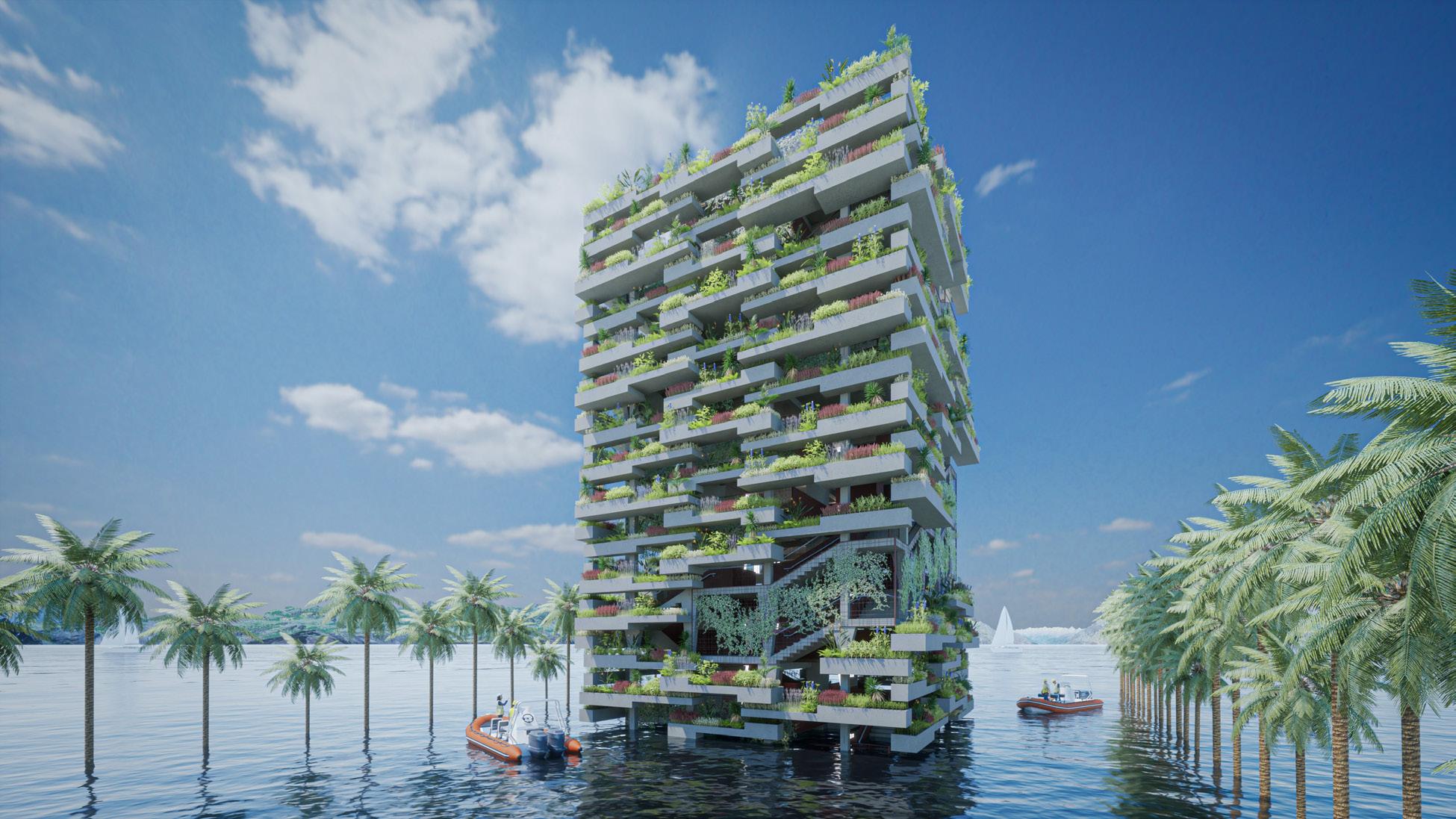
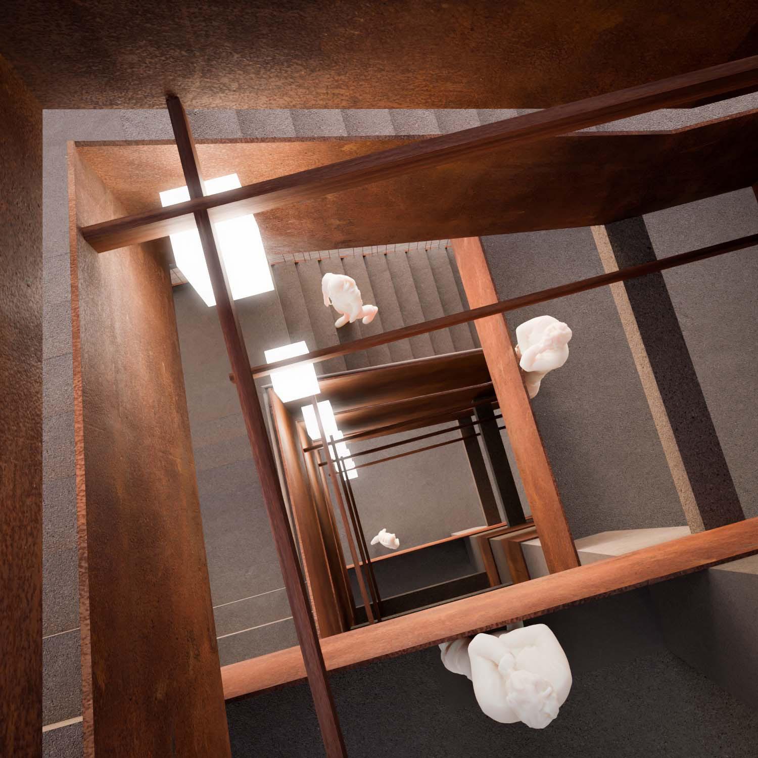
The basis for this tsunami evacuation tower is a shifting double stacked spiral staircase with a fully planted façade that is interwoven with steel plating and mesh. The structure is based on a stacked column system that incorporates corbels to support the floor plates, stairs and facade. The stairs, as mentioned before, are doubled up to allow more circulation in the event of a tsunami, and when they line up with each other they become a mass one can either walk on top or inside of. The column grid is made up of a core of 2ft diameter columns to support the main structure surrounded by a perimeter of 1ft columns to mainly support the facade planters. The voids created by the gap between the stairs and the core introduce vertical shafts of varying heights which can be utilized in anything from HVAC to lighting. What was done to further emphasize the modulation of the project was to translate that to our facade. Which is orientated in the horizontal direction to juxtapose the verticality of the tower. The facade plays with the idea of push and pull in the dimensions of their widths to create variety. Variety in the facade is even further emphasized by the implementation of vegetation. These qualities are translated both in the exterior and interior of the project as seen in the renderings. The facade was then translated into the design of the site, a reference to the IBM building in Hawaii. The datums set up by the scheme of the facade onto the ground level allowed us to create a fragmented site design. Flexibility between each of the sites is introduced in the design of the facade, the planters adjust in vegetation and planter design depending on the location of the site.


The Kailua Beach site is situated at the Kalama Beach Community Center. The tower is to sit aligned with the historical Kalama Beach Community Center building to face the predominantly residential side of the site alongside an expanded parking area and public transit stop. The town of Kailua has a population of around 60,872 and the tsunami evacuation zone for wave heights of 20-30 feet will affect around a third of the residents on the coast. The residential neighborhood will have our tower placement, Lanikai Pillbox, and moving around half a mile inland as the primary escape zones. In the case of extreme tsunamis that are estimated by the State of Hawaii’s Emergency Management Agency to be at 65-70 feet in height the escape zones would be the designed escape tower, Lanikai Pillbox, and the Hāmākua Marsh Wildlife Sanctuary for immediate escape at around 30 minutes of being alerted.


The Ala Moana neighborhood of Honolulu County in Oahu has a population of around 20,348residents with a heavily commercial and tourist filled region near the Ala Moana shopping center that parallels Magic Island Park. The proposed evacuation tower will be situated within the redesigned Magic Island that will have a greater emphasis on pedestrian access and bike pathways as the vehicle access will be shifted toward the coordinated structure that was designed in collaboration with the students at University of Hawaiʻi at Mānoa. According to data from the County of Honolulu the average Tsunami height expected is 20 to 30feet, with extreme zones estimated to be 60-70 feet, which would be at around half the height of our tower design. The tower is set to be designed with recreational sports and equipment rental for kayaks or surfboards at the base level. The additional levels will also have office spaces for lifeguards and medical spaces that are to serve for any immediate emergencies, while also allowing storage for vital supplies during tsunamis. Community gardens will be placed in the other floors in order to foster community events and to help the homeless population with food safety, alongside the clinic that can serve rehabilitation programs.

The tower is set to hold around 2,500 people in the worst-case scenario of an extreme tsunami and has been placed to take in the busy tourist area of Magic Island with around a 30 minute walking head start in mind.


The Venice Beach Neighborhood in Los Angeles County is a small vibrant neighborhood of around 29,135 residents. The tsunami evacuation zone as researched from the California Department of Conservation for the Venice Beach site will affect a large number of residential homes and the highly trafficked tourist zone of Venice Beach itself. The tsunami evacuation zone is at the estimated height of 20-25 feet with much of the evacuation zone persisting within the large Marina Del Rey boating yards and the major evacuation routes being toward the Santa Monica Airport to the North of the site. The tower is expected to hold around 3,000 people in the case of emergency and has been designed to allow ease of pedestrian access to the site itself.

Based off our site research, for Venice an outdoor gym was chosen due the history of competitive body building within Muscle Beach and also the recent pandemic need for outdoor programs. In order to conserve water and reflect the California Coast, the planters will be seeded purely with American beach grass which can be sustained with little maintenance. So that the context of Venice, which contains many white buildings punctuated by vibrant colors, could be reflected, a concrete aggregate of fine white sand mixed with clear quartz was chosen which can reflect the many changing colors of the sky.


PHYSICAL CONCEPTUAL MODEL STUDY
Duality: Shifting Materiality Testing
Duality
Shifting Materiality Testing
This study of both space variations and materiality in terms of both model and representation evolved over several stages. It started off as a simple grid based excercise with cuts made at random to obtain 3 separate types of volumes that were greater solidified in chipboard models. These 3 types of 3D volumes were to be connected by circulation with the only limitation being to ascend from ground level to the uppermost level, which lead to engraving a staircase within existing volumes to make use of shadows and apertures for a more stimulating means of travel for any proposed visitor. The chipboard model would be remade to a more refined museumboard model with an emphasis on creating an entrance for the circulation. The final translation of this model excercise was to create a dual material final model of the past volume with basswood half inch repeatable modules and a solid hyrocal base to serve as a strong foundation for the circulation to rest within. The change of scale and the creation of a waterproof mold with texture were the strongest learning lessons for this project.


