


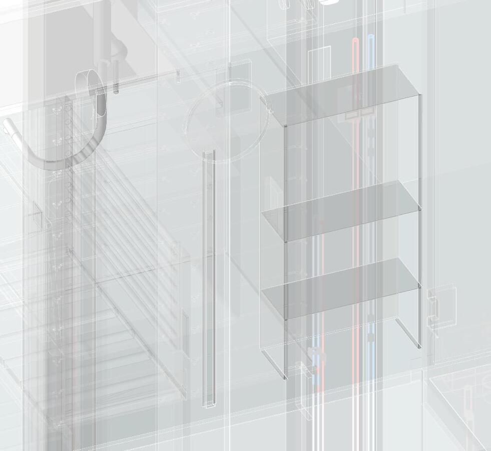
BILL OF MATERIAL
MARK DESCRIPTION SIZE QTY
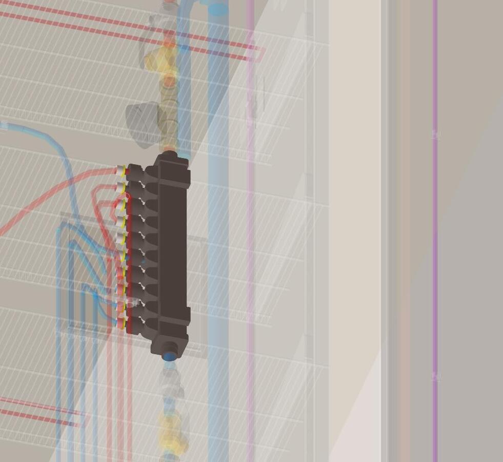
A1 6 WAY MANIFOLD 1 6 WAY
B1BALL VALVE1
C1SHUT-OFF1
D1WATER METER1 B2 1 C2 1
D21 WATER METER BALL VALVE
SHUT-OFF
MARK DESCRIPTIONSIZE QTY
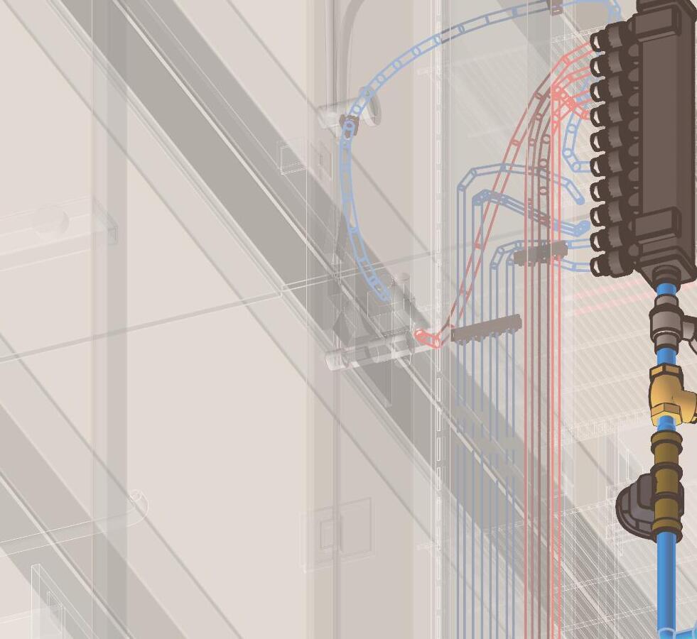
H1 DOMESTIC HOT WATER-PEX
H2DOMESTIC HOT WATER-PEX
H3DOMESTIC HOT WATER-PEX
H4DOMESTIC HOT WATER-PEX
H5DOMESTIC HOT WATER-PEX
H6
H8
DOMESTIC HOT WATER-PEX
H7DOMESTIC HOT WATER-PEX DOMESTIC HOT WATER-PEX
DOMESTIC COLD WATER-PEX
DOMESTIC COLD WATER-PEX C2
DOMESTIC COLD WATER-PEX
DOMESTIC COLD WATER-PEX
DOMESTIC COLD WATER-PEX
DOMESTIC COLD WATER-PEX
THIS IS TO BE PRE-ASSEMBLED EITHER IN A SHOP, OR DESIGNATED PRE-ASSEMBLY AREA ON SITE FLAT ON AN ASSEMBLY TABLE.
THE COMPLETED ASSEMBLY IS TO BE DELIVERED TO THE INSTALL LOCATION AS ONE UNIT THESE DIRECTIONS INCLUDE CUTTING LENGTHS OF PIPE TO LENGTH. WHERE LENGTHS ARE PRE-CUT BY THE MATERIAL SUPPLIER, EXCLUDE THESE STEPS AND PROCEED DIRECTLY TO ASSEMBLY.
M8 (1) @ xxx
M9 (1) @ yyy
M10 (1) @ zzz
M11 (1) @ zzz
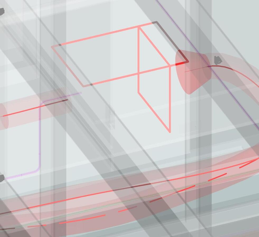
STEP 1: CUT STOCK LENGTH OF DIAMETER CPVC PIPE INTO THE PARTS AND LENGTHS BELOW:
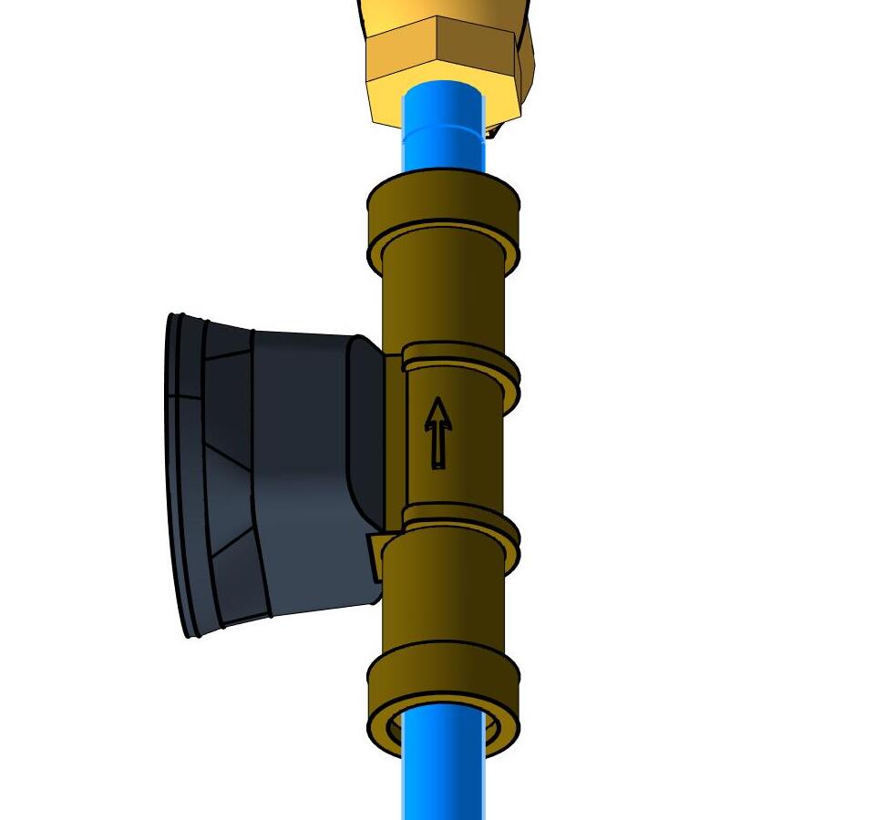
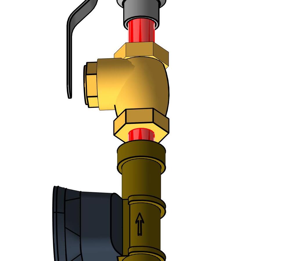
STEP 2: CONNECT REDUCER FITTING M2 TO EACH END OF THE MANIFOLD INLET, USING TEFLON TAPE TO SEAL THREADS OF MANIFOLD TO ADAPTER CONNECTION
STEP 3: USING PLUMBER'S CEMENT, GLUE PIPES M11 TO M2
STEP 4: USING PLUMBER'S CEMENT, GLUE M3 TO M11 ON THE HOT SIDE OF THE MANIFOLD
STEP 5: USING PLUMBER'S CEMENT, GLUE M6 TO M11 ON THE COLD SIDE OF THE MANIFOLD
STEP 6: USING PLUMBER'S CEMENT, GLUE PIPES M10 TO EACH M3 & M6
STEP 7: USING PLUMBER'S CEMENT, GLUE SHUT OFF VALVE M4 TO M10 ON THE HOT SIDE OF THE MANIFOLD
STEP 8: USING PLUMBER'S CEMENT, GLUE SHUT OFF VALVE M7 TO M10 ON THE COLD SIDE OF THE MANIFOLD
STEP 9: USING PLUMBER'S CEMENT, GLUE PIPES M9 TO EACH M4 & M7
STEP 10: USING PLUMBER'S CEMENT, GLUE ELBOWS M12 TO EACH M9
STEP 11: USING PLUMBERS CEMENT, GLUE PIPES M8 TO ELBOWS M12


NOTE:


Cold Water Pex From Manifold to Sink
1 laborer 15 min
Water Pex From Manifold to Sink J 18 Clips -
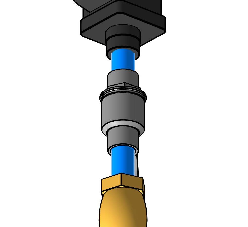
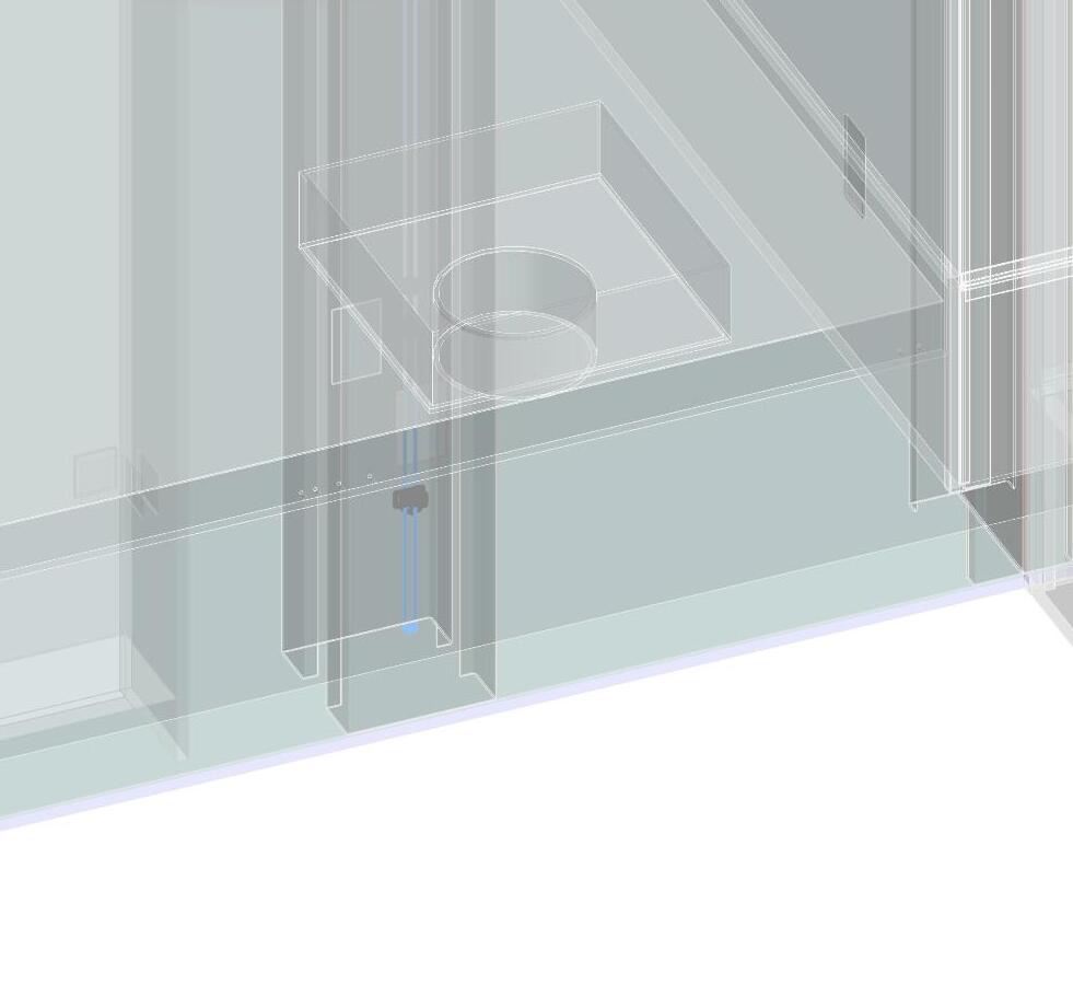
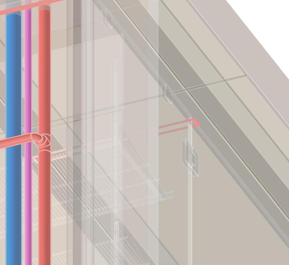
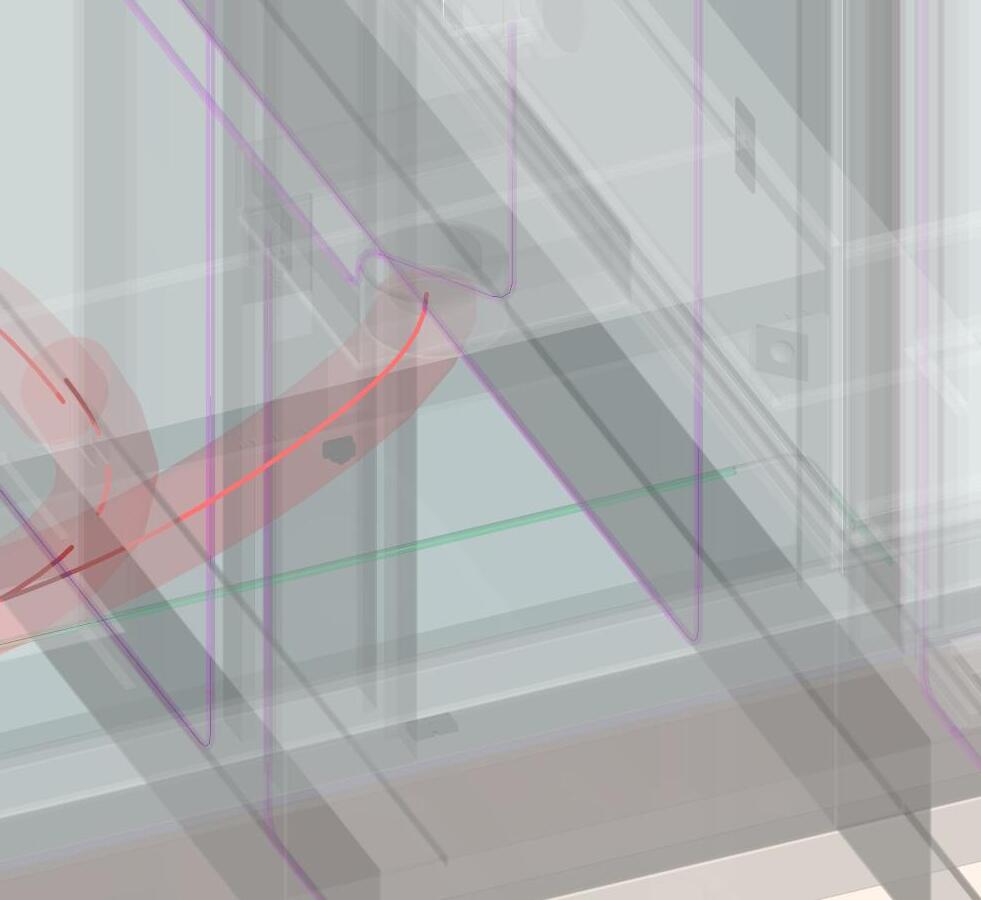
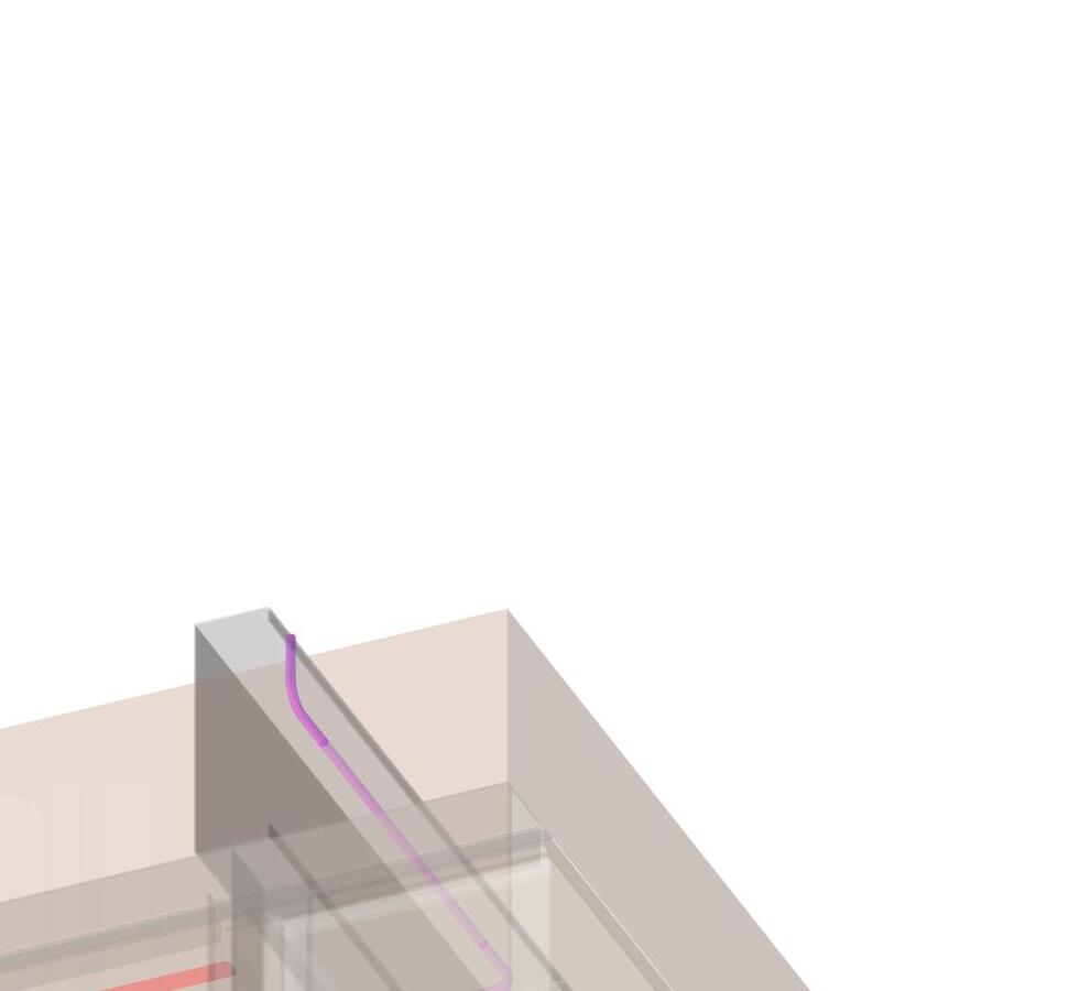
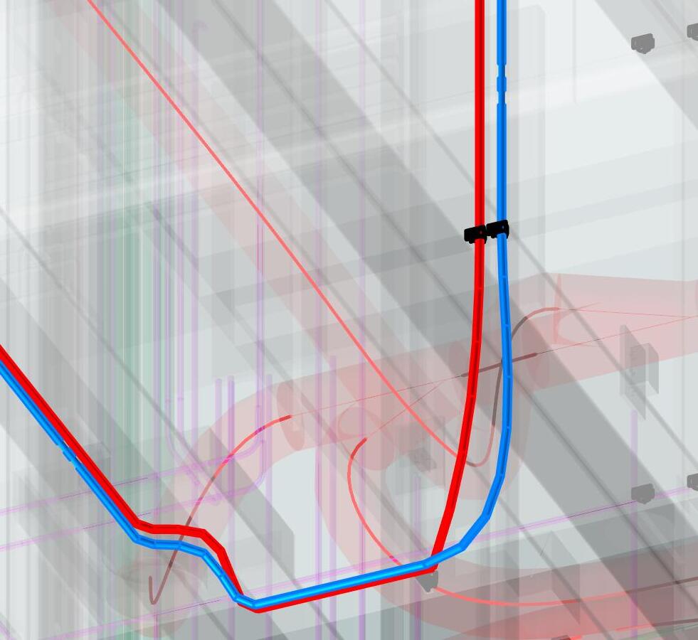
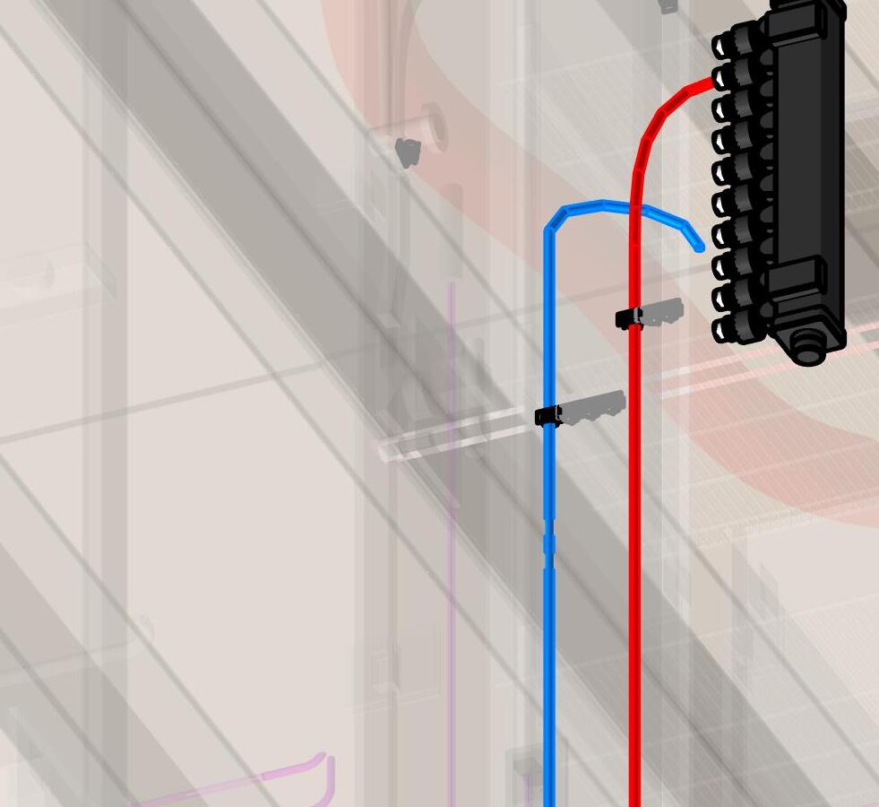
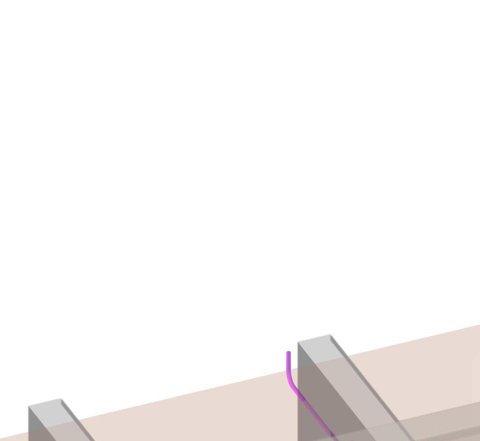
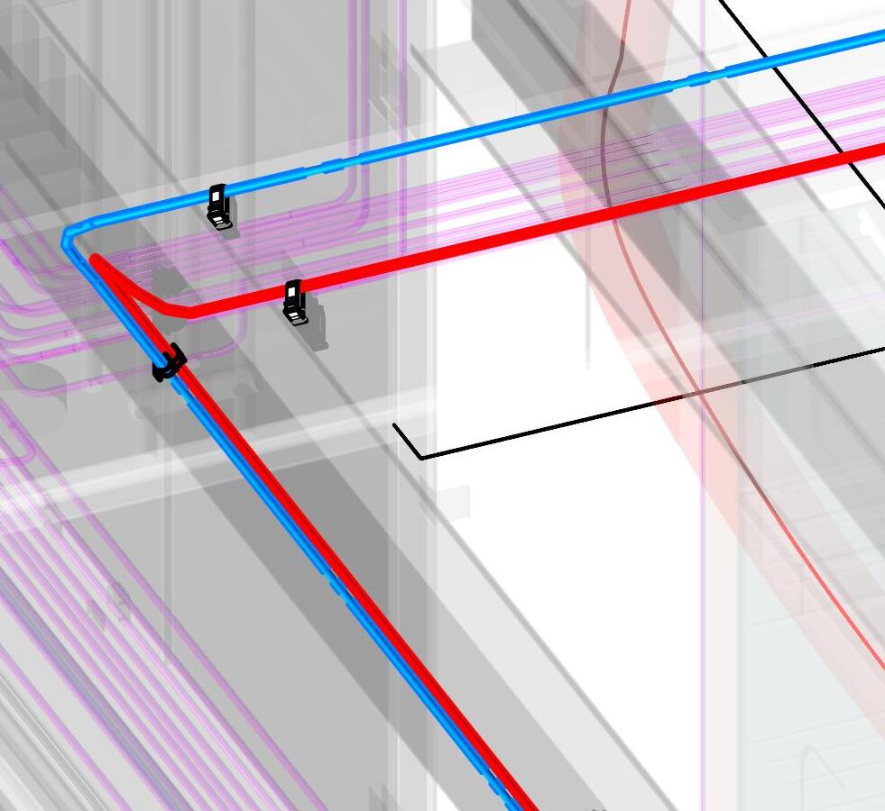
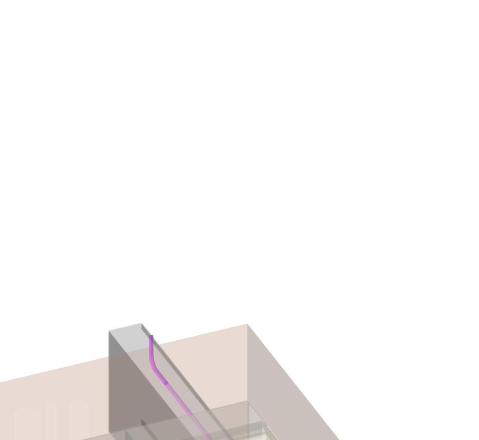
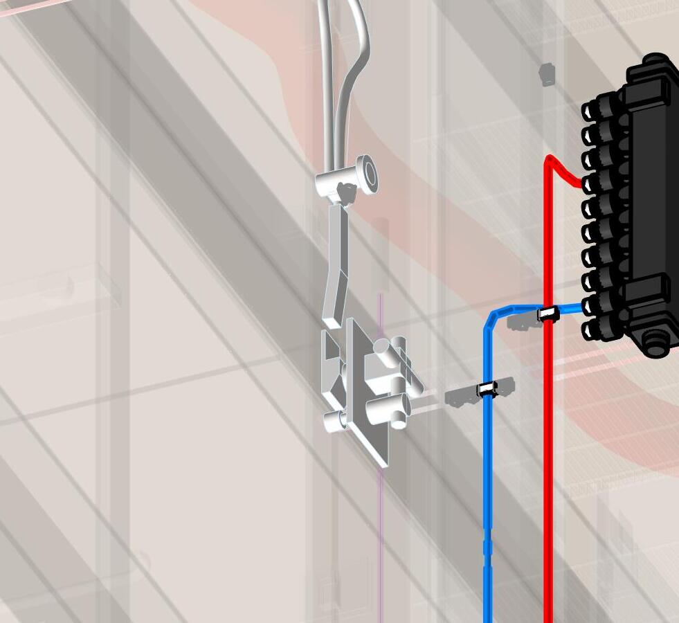
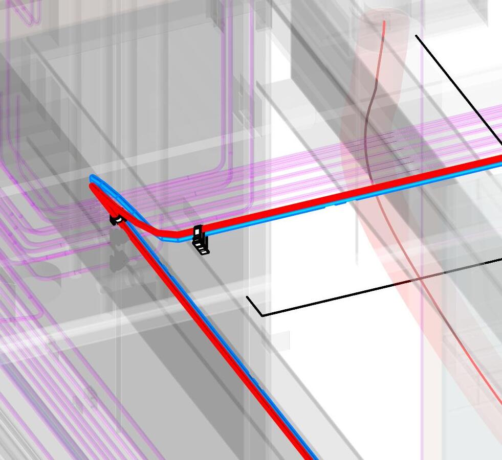
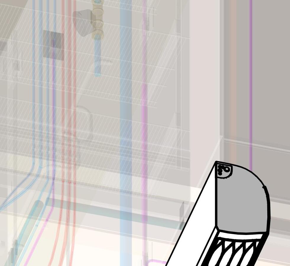
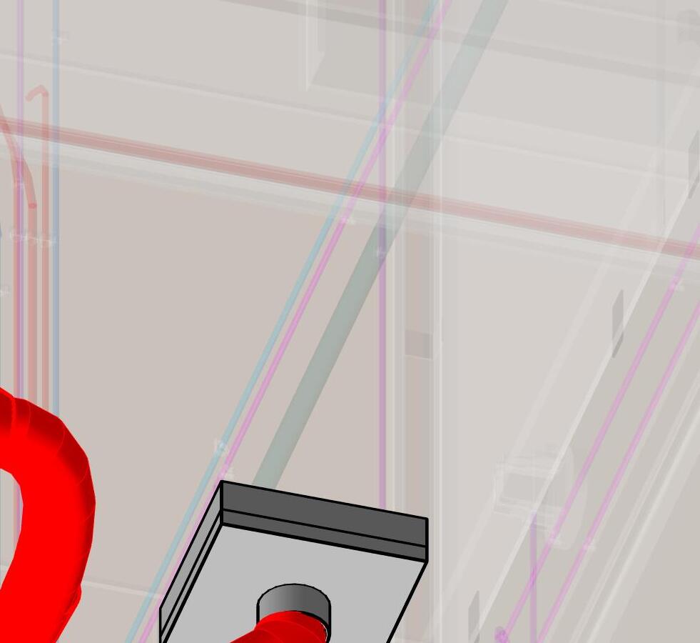
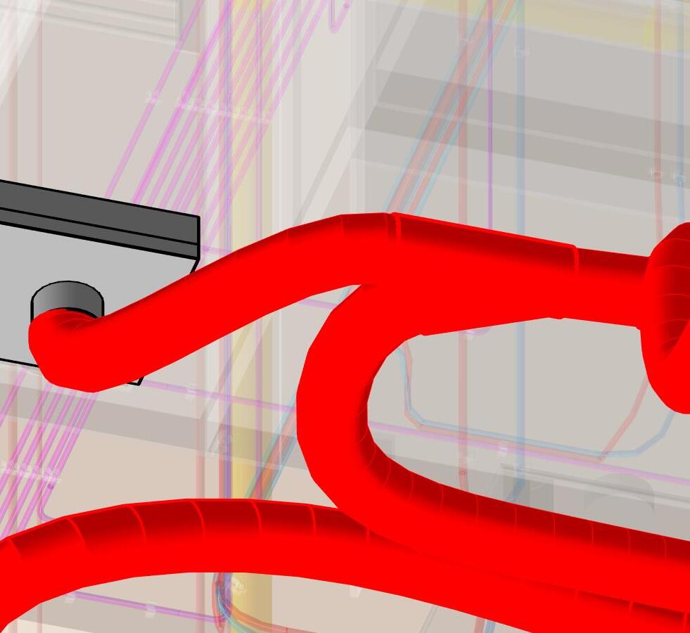
-Starting on the floor infront of the manifold, connect one end of each pre-cut supply pex (SSS, TTT) to the manifold with a crimp (LLL).
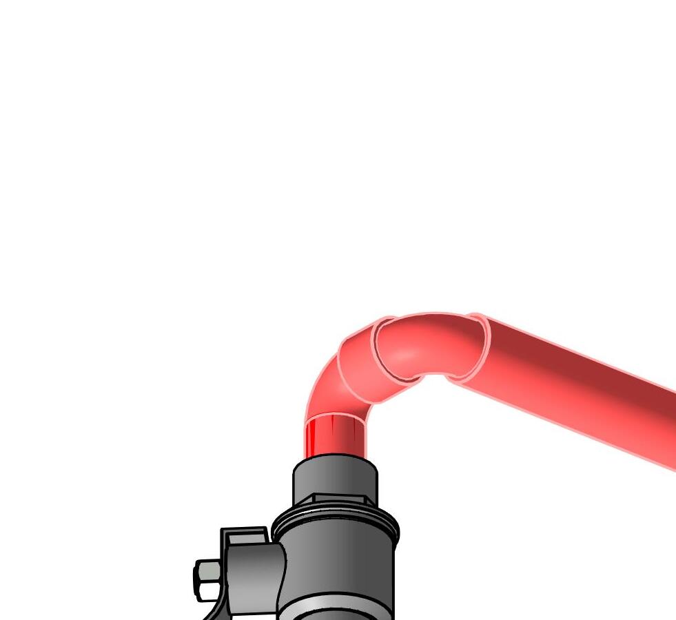
-Secure the supply lines (SSS, TTT) to the densglass at the end of the radius turning up from the manifold connection with a pex clip (MMM) and drywall screw (NNN)
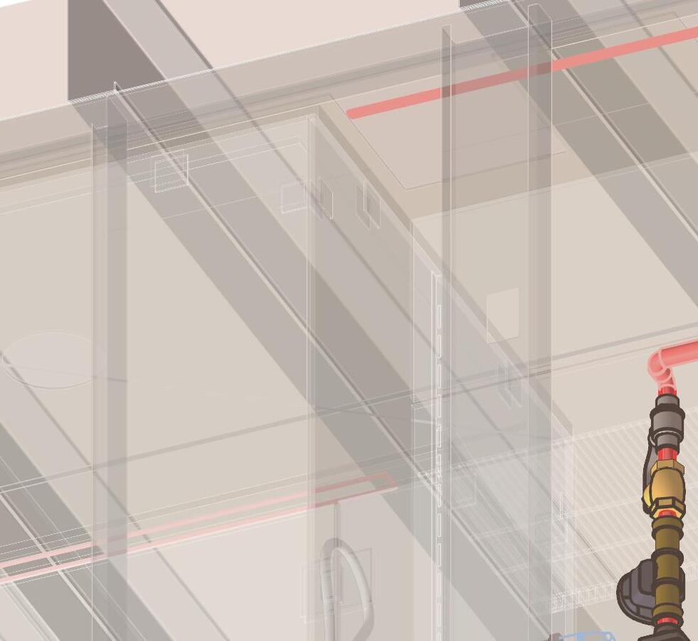
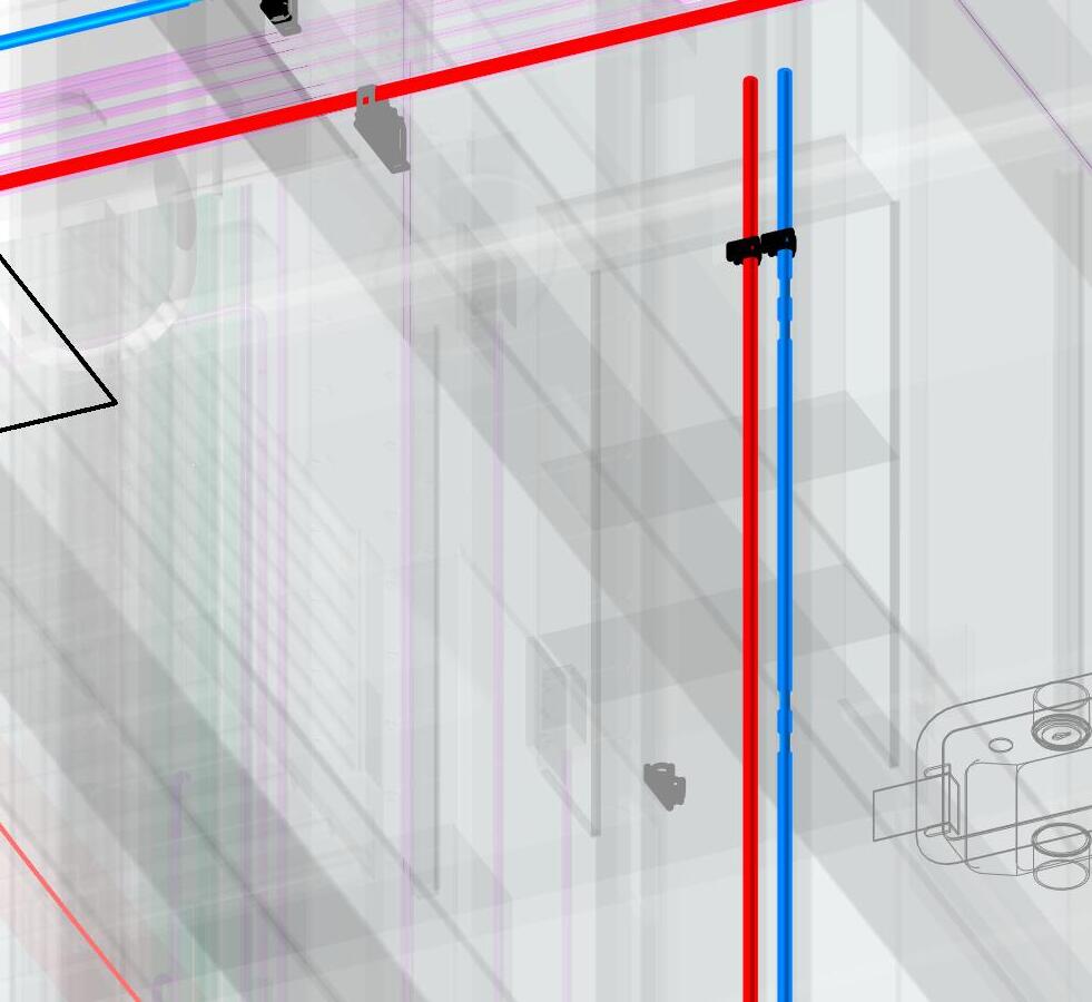
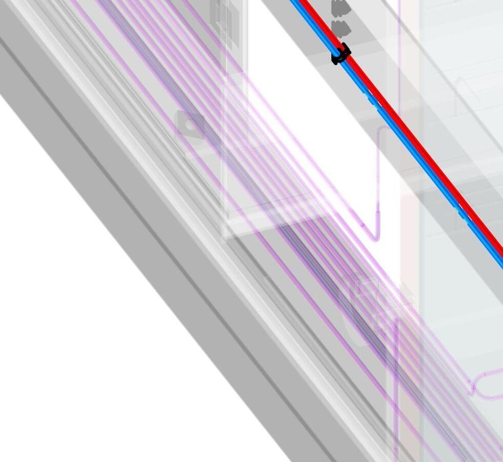
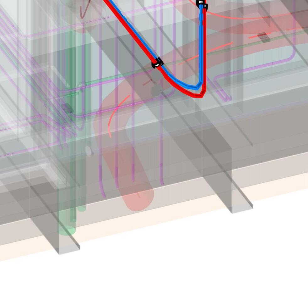
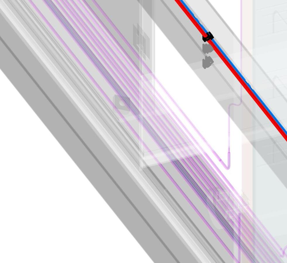
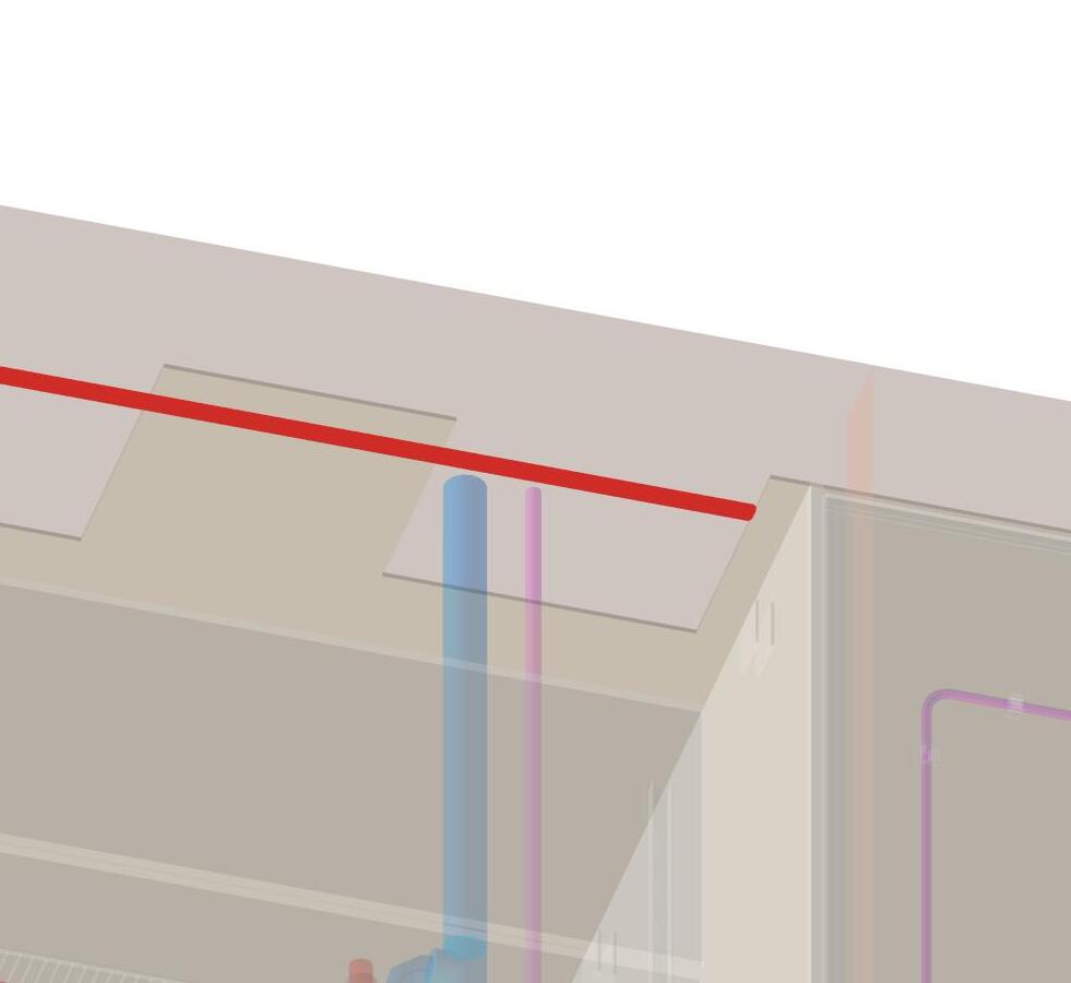
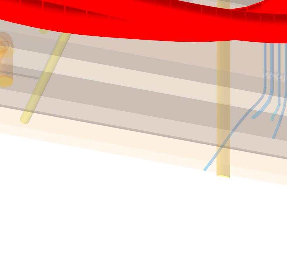
-Using a ladder to access the ceiling, pull the supply pex (SSS, TTT) up to the joist above. at end of radius from wall to ceiling bend, secure to joist with a pex clip (MMM) and self tapping screw (OOO) into the joist
NOTE:
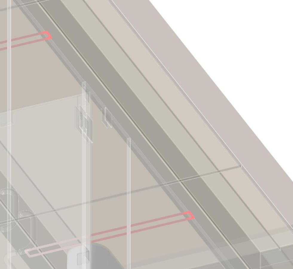
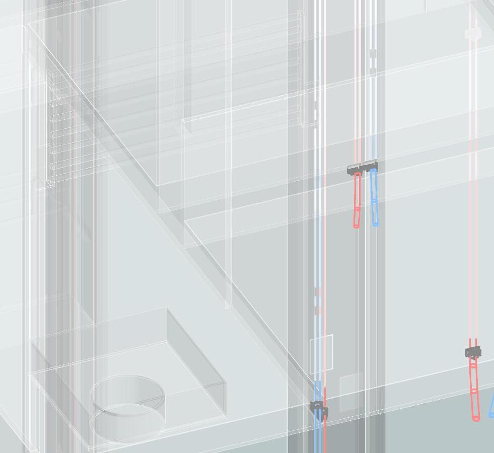
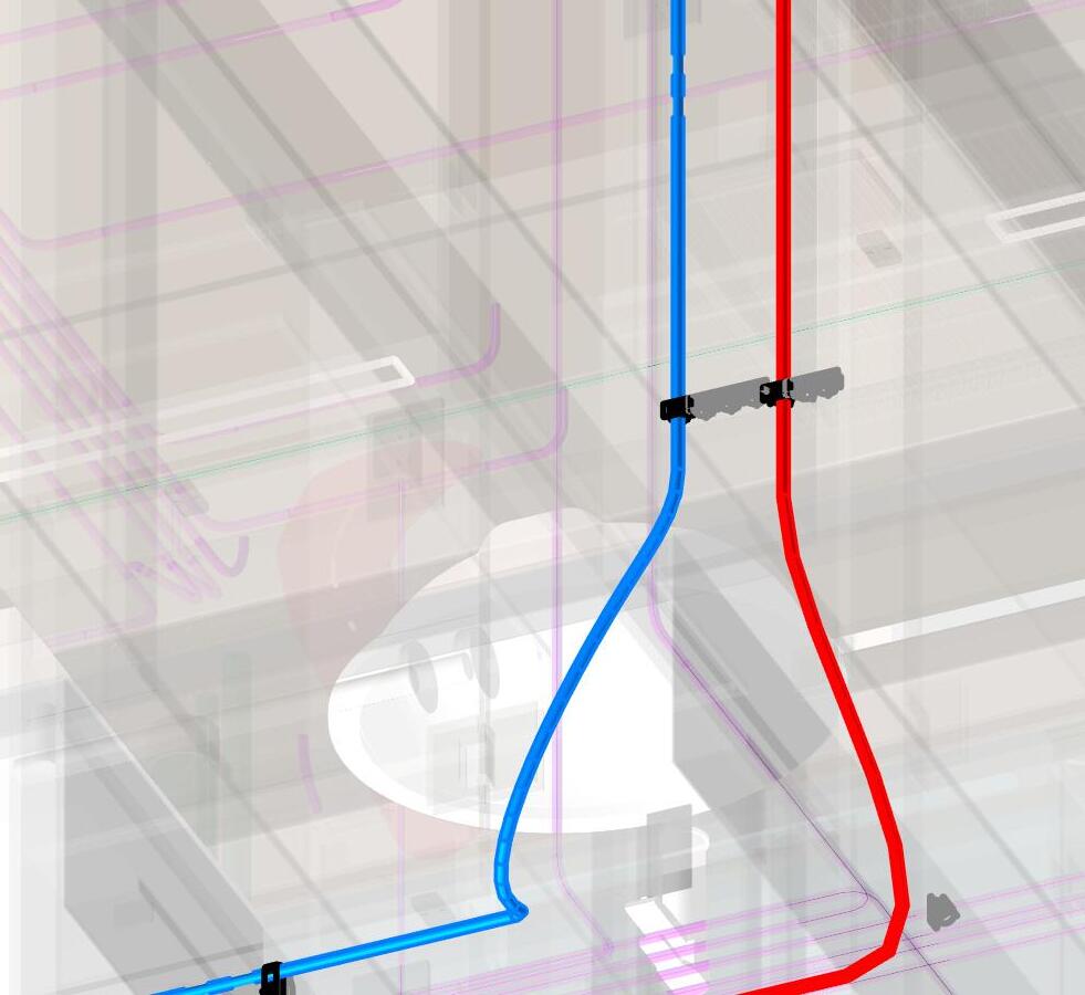
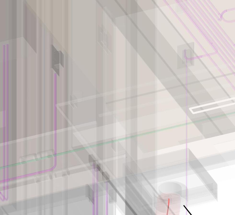
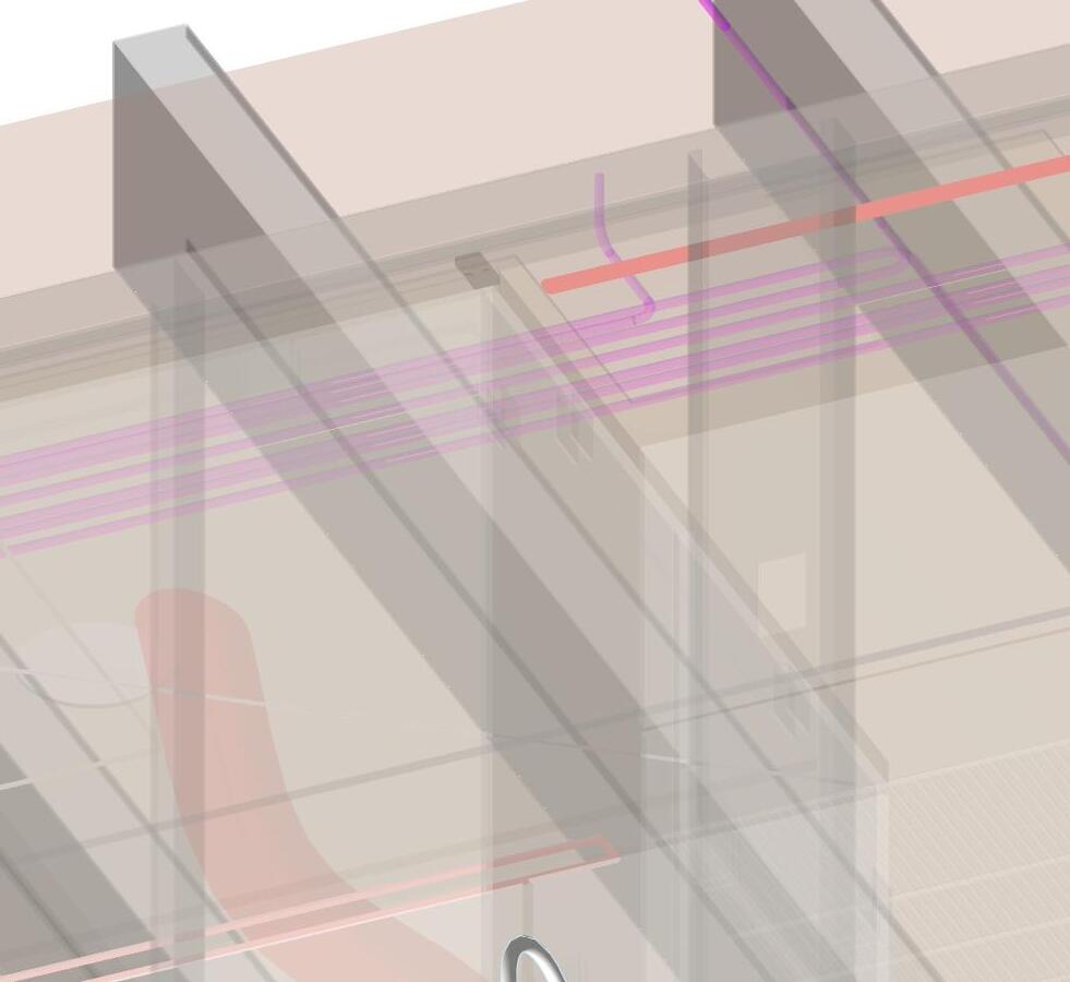
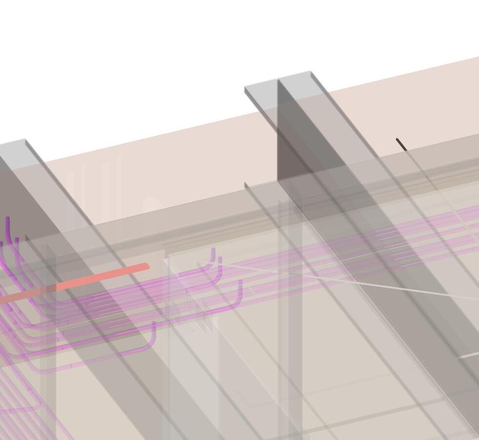
-Attach the pex lines (SSS, TTT) to the side of the joist at two intervals across the unit with (MMM and OOO).
-Coil and hang (SSS, TTT) in joist depth for later connection to vanity sink supply


1 laborer 15 min
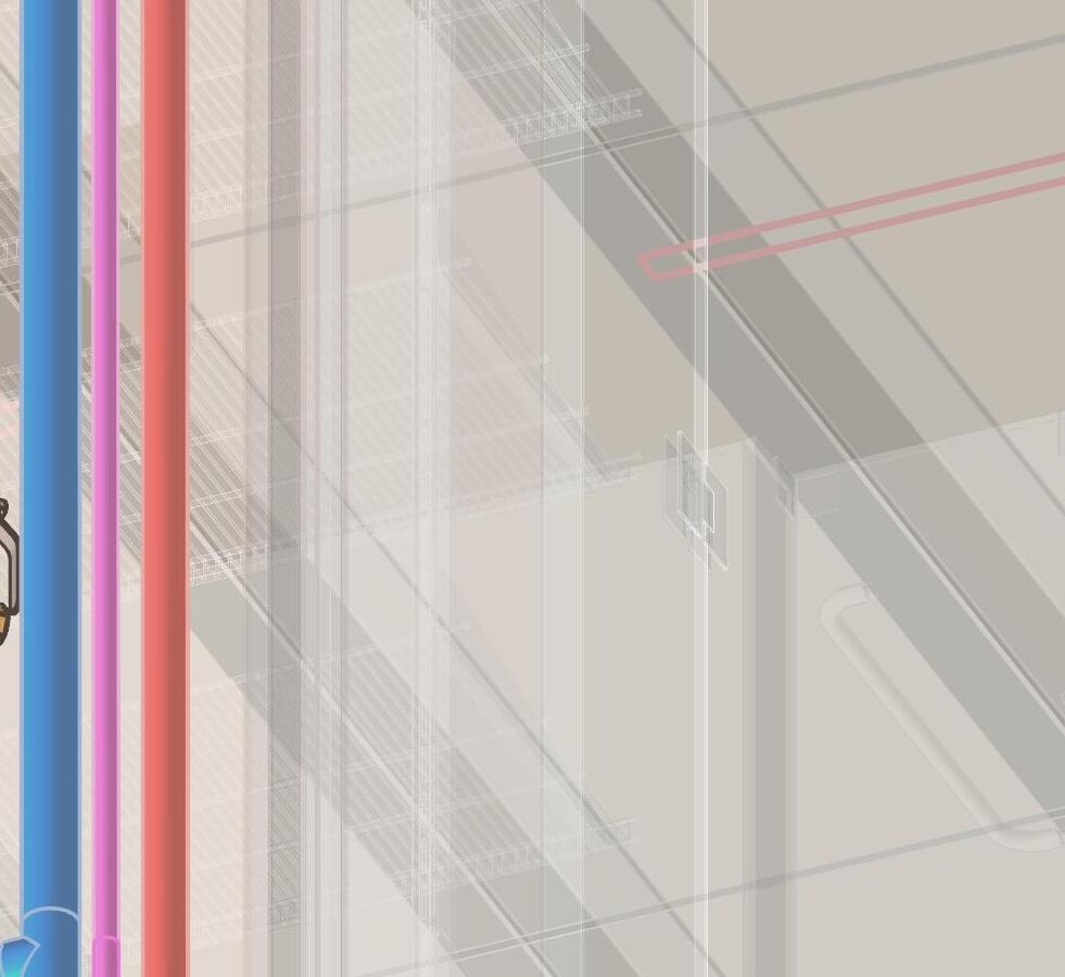
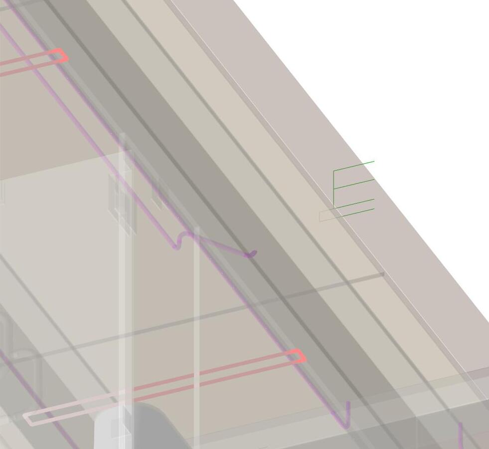
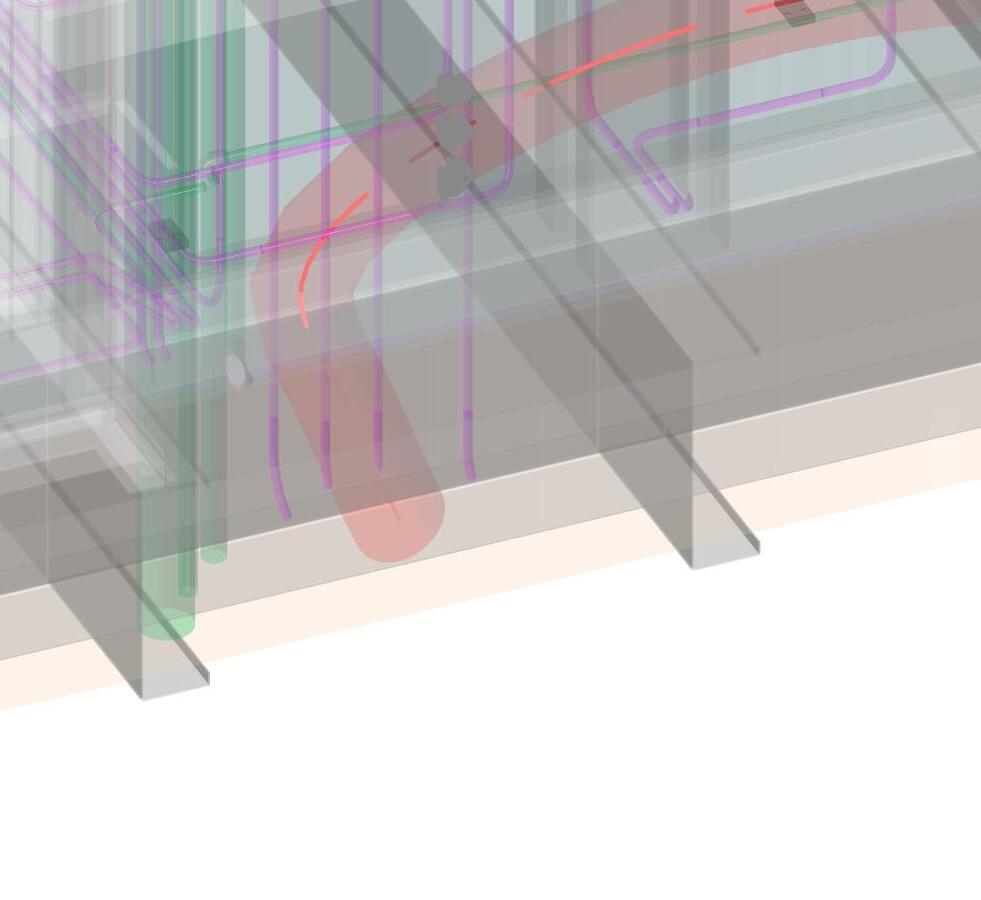
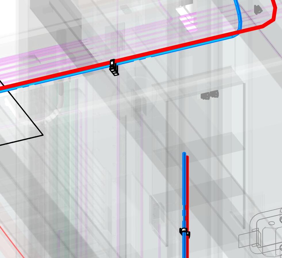
D Cold Water Pex From Manifold to Kitchen Sink Hot Water Pex From Manifold to Kitchen Sink J 16 Clips -
-Starting on the floor infront of the manifold, connect one end of each pre-cut supply pex (UUU, VVV) to the manifold with acrimp (LLL).
-Secure the supply lines (UUU, VVV) to the densglass at the end of the radius turning up from the manifold connection with a pex clip (MMM) and drywall screw (NNN)
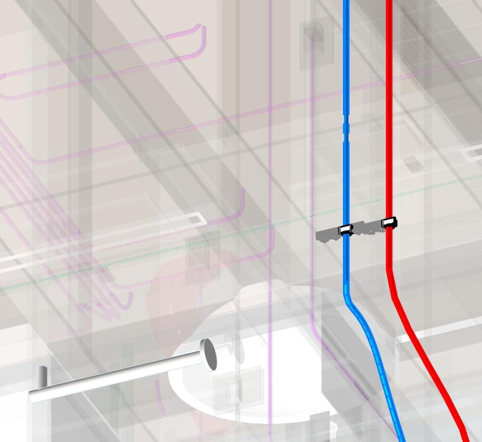
-Using a ladder to access the ceiling, pull the supply pex (UUU, VVV) up to the joist above. at end of radius from wall to ceiling bend, secure to joist with a pex clip (MMM) and self tapping screw (OOO) into the joist
NOTE:
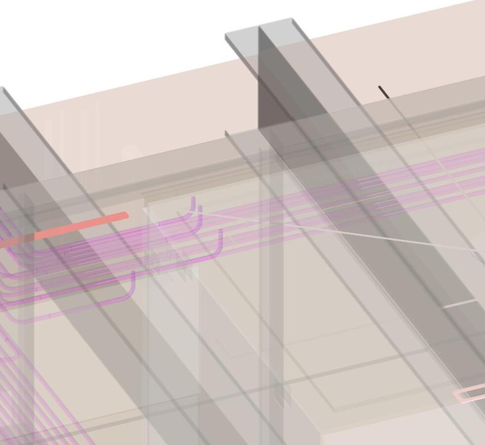
-Attach the pex lines (UUU, VVV) to the side of the joist at twointervals across the unit with (MMM and OOO).
-Coil and hang (UUU, VVV) in joist depth for later connection to kitchen sink supply


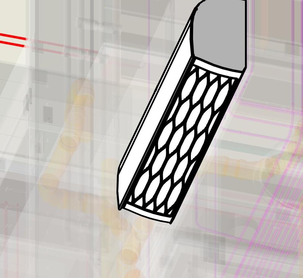


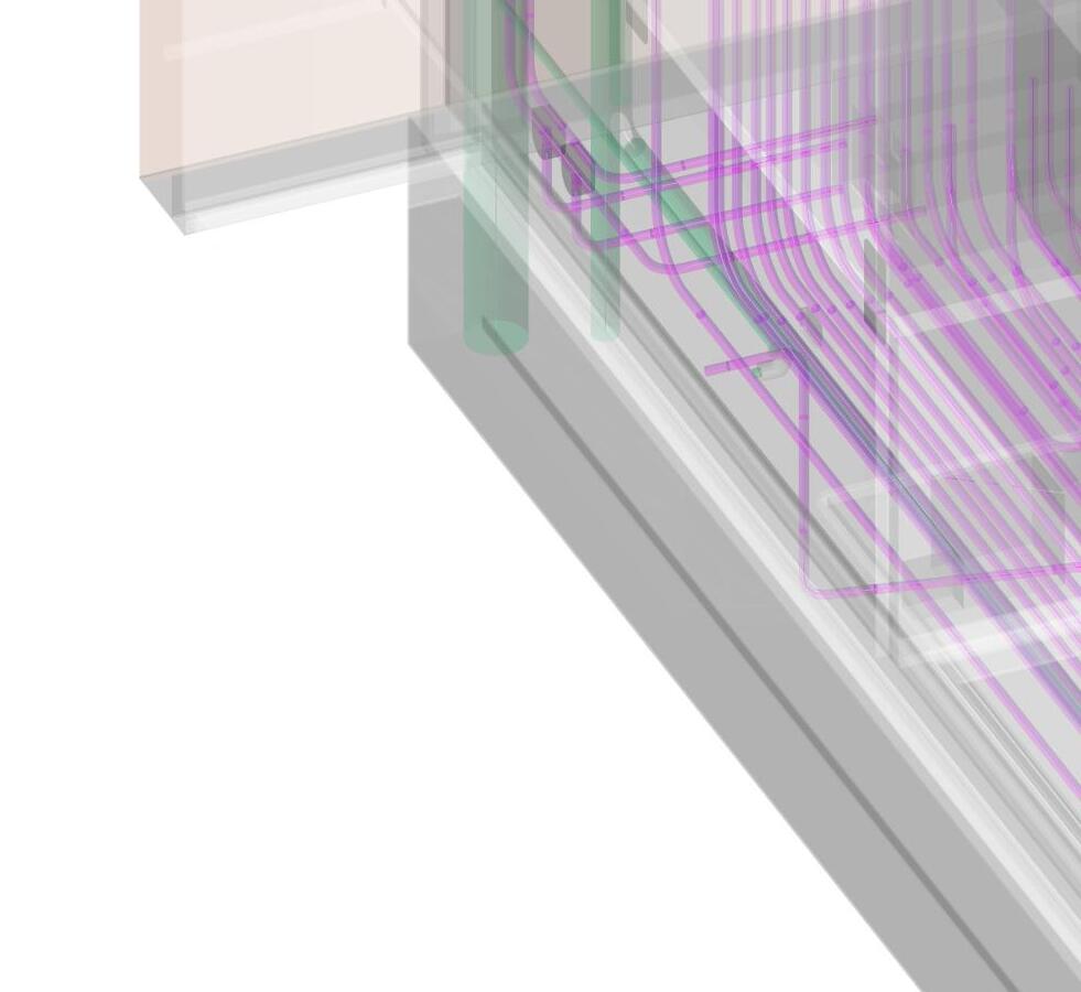
DESCRIPTION
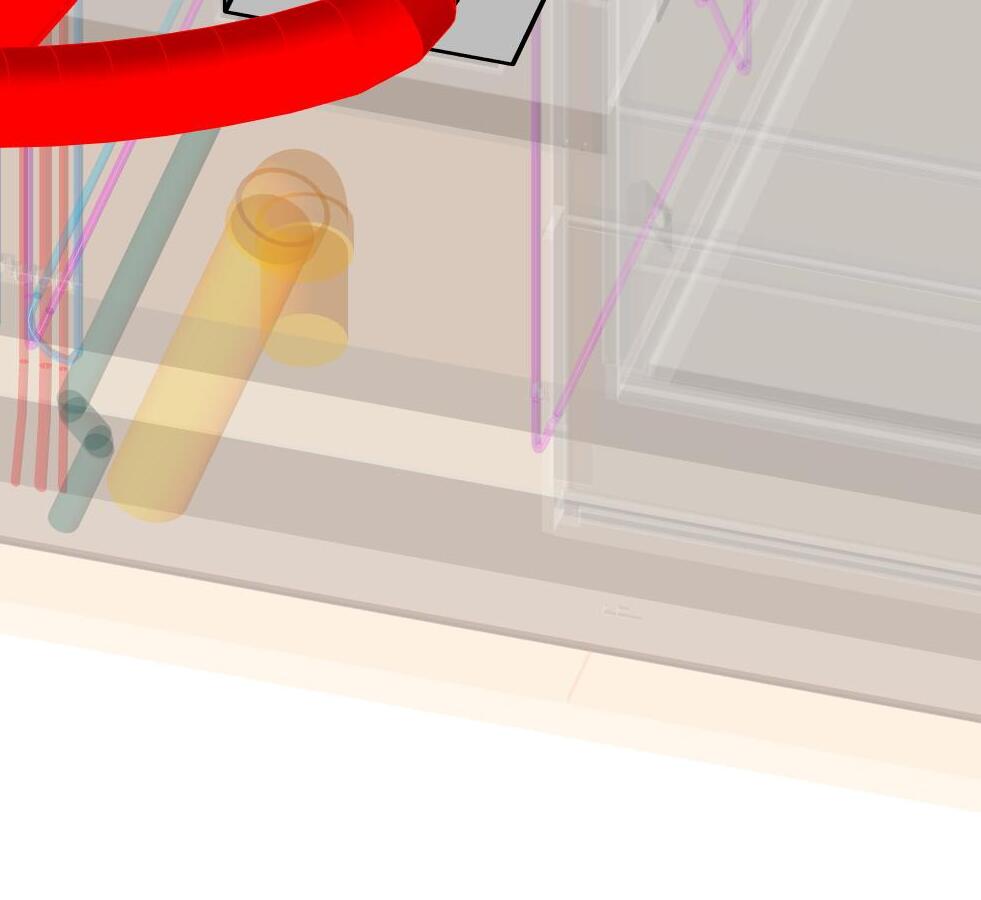
CEILING EXHAUST
FLEX DUCT-VANITY TO WHY FITTING
FLEX DUCT-TOILET TO WHY FITTING
FITTING
FLEX DUCT-SHOWER AREA TO WHY FITTING
INLINE FAN
TRANSITION
F FLEX DUCT- WHY FITTING TO FAN G FLEX DUCT FROM WHY FITTING TO INLINE FAN
UNIT
J FLEX DUCT FROM UNIT FAN TO LOUVER -