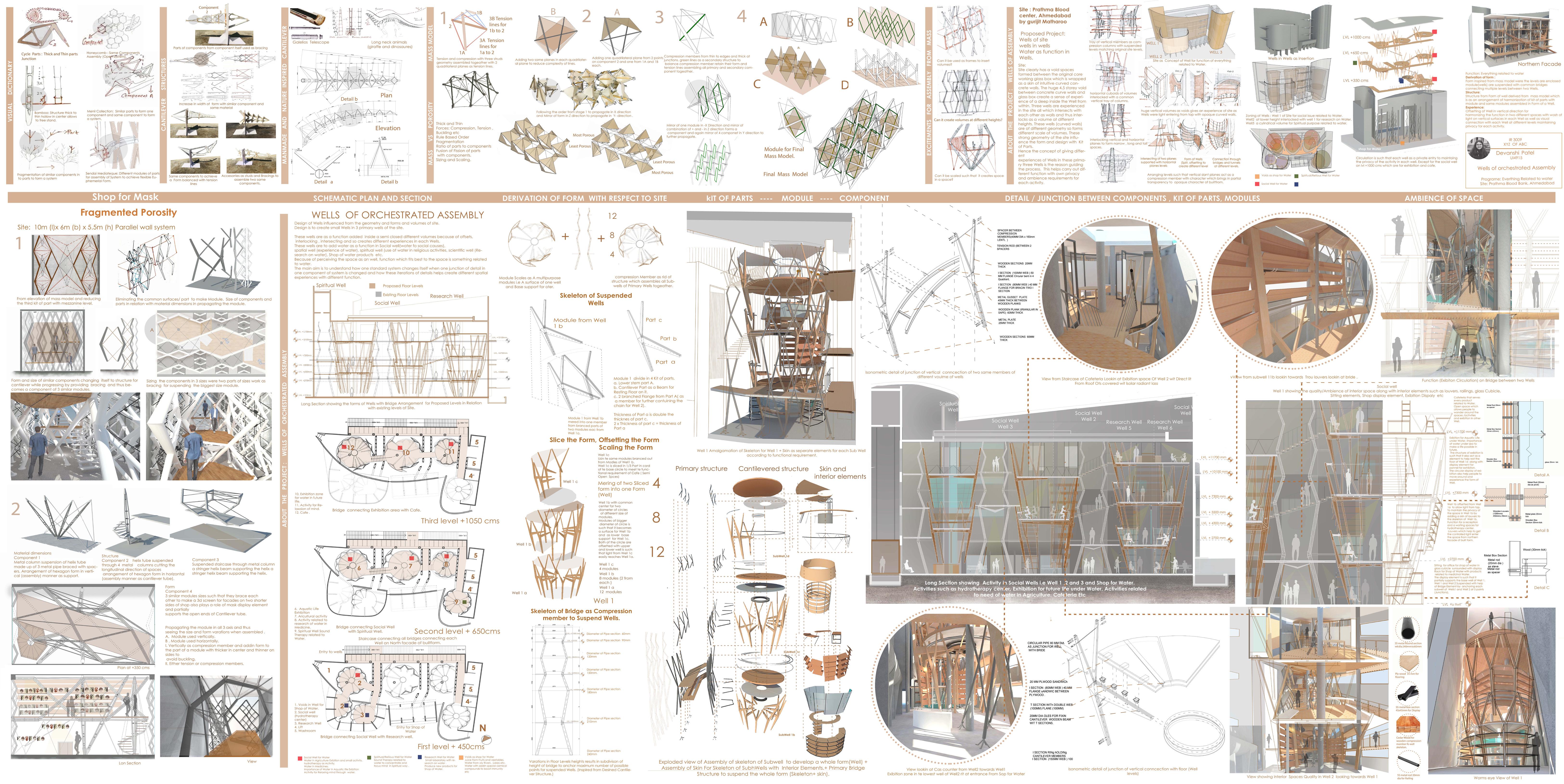

Week 1- Week 8
On March 6th we completed our mid-semester review and have been online since March 16th. Following presentation is Week 8 onwards......
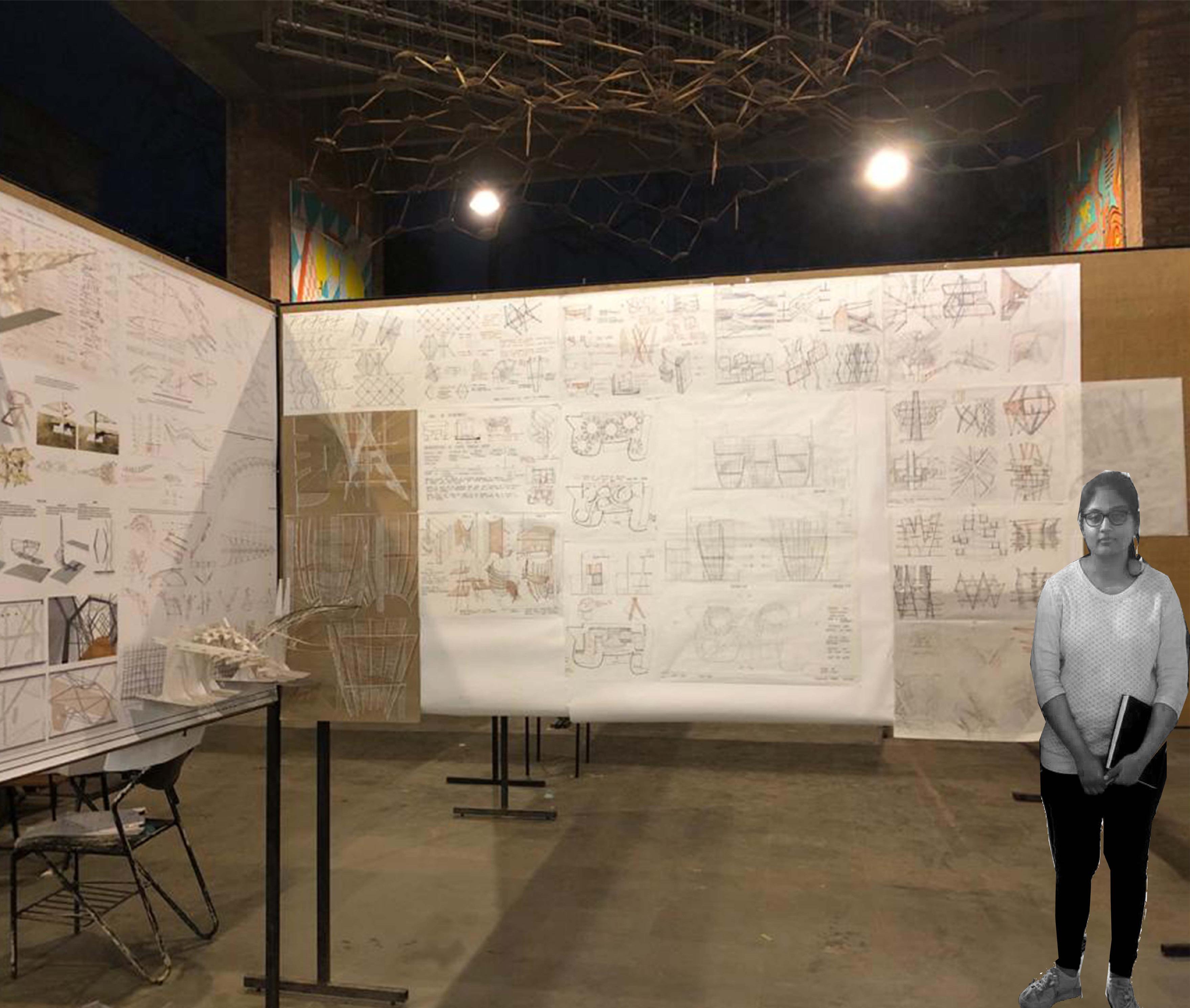
Devanshi Patel UI4915

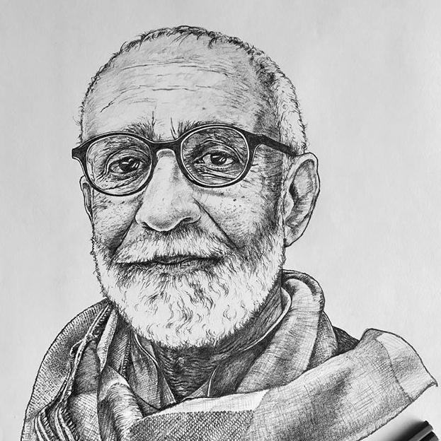
Studio Tutor: Prof. Kireet Patel (Sketch Courtesy: Anand Vishwanathan)
Studio TA: Chandni Chhabra

Mid-Semester Process Panel (Week 1 to 8)
1. ASSEMBLY BASED CONSTRUCTION ALWAYS RELATED TO TECHTONICS? 2. W AT DEFINES E OPEN AND CLOSED SYSTEM IN ASSEMBLY BASED CONSTRUCTION ? 3. IS ASSEMBLY BASED CONSTRUCTION ALWAYS A RULE BASED SYSTEM? 4. HOW TO DECIDE FROM BELOW OPTIONS? a. STANDALONE SYSTEM INSIDE EXISTING FORM/SITE? b. SYSTEM DEVELOPED/DEVELOPING IN HARMONY WIT EXISTING SITE/ FORM? 5. ASSEMBLY BASED CONSTRUCTION IS USED TO REDUCE COMPLEXITY OR CONSTUCTION WITH COMPLEXITY 6. WHAT ASSEMBLY BASED CONSTRUCTION A FUSION OR FISSION OF ELEMENTS? 7. DOES EVOLUTIONARY ALGORIT M ALWAYS SERVES AS MODEL FOR ASSEMBLY BASED CONSTRUCTION? 8. W AT ALL OF SPATIAL VERBS ARE OR CAN BE PART OF ASSEMBLY BASED CONSTRUCTION? 9. DOES JUNCTIONING OF COMPONENT 1+ COMPONENT WITH DETAIL IS ASSEMBLY BASED CONSTRUCTION? 10. WHAT ARE H TYPE OF SYSTEM IN ASSEMBLY BASED CONSTRUCTION? 11. W AT IS ROLE OF DETAIL IN ASSEMBLY BASED CONSTRUCTION? 12. DOES T FORM DERIVED IN ASSEMBLY BASED CONSTRUCTION ALWAYS CONSIDERS LIGH PRIMARY FACTOR TO DERIVE AT PARTICAL FORM? 13. WHAT IS TE ROLE OF ASSEMBLY BASED CONSTRUCTION IN KINETIC STRUCTURES CONSTRUCTION? 14. DOES ASSEMBLY BASED ARCITECTURE AVE PARTICULAR ASSEMBLY OR ORDER OF PARTS? (CORE, INTERMEDIATE ELEMENT, SKIN) 15. DOES ASSEMBLY BASED CONSTRUCTION ALWAYS HAVE TO SELF STANDING/ BALANCED? 16. IS EIR RELATION BETWEEN SYSTEM AND TEC NIQUE OF DEVELOPING AT SYSTEM? 17. ASSEMBLY BASED CONSTRUCTION MANUAL FORCE GOVERNED DESIGN OR TEC NOLOGY GOVERNED? 18. WHAT CAN BE RATIO OF PARTS AND COMPONENTS FOR ASSEMBLY BASED CONSTRUCTION? 19. OW CAN BE EXPLAINED ABOUT DIFFERENT C ARACTER OF COMPONENT ASSEMBLED IN LINEAR COMPOSITION IN ASSEMBLY BASED CONSTRUCTION? 20. CAN ASSEMBLY BASED CONSTRUCTION HAVE SINGLE MODULE OF ONE MATERIAL WITH DIFFERENT ORANIZATION?
Mass Models
CM CM CM CM CM O CM 200mm IRON ROD SLEVE 250mm STEEL TUBE METAL PLATE 10mm METAL ROD SPACER
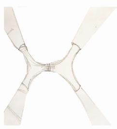
SIZE OF COMPONETS AND PARTS IN RELATION WIT MATERIAL DIMENSIONS IN PROPA ATIN MODULE. SIZE OF COMPONETS AND PARTS IN RELATION WITH MATERIAL DIMENSIONS IN PROPA ATIN MODULE. ELIMINATIN COMMON SURFACES/ PART TO MAKE MODULE. SIZE OF COMPONETS AND PARTS IN RELATION WITH MATERIAL DIMENSIONS IN PROPA ATIN H MODULE.
JUNCTIONS DETAILS BY SEEIN PARTS JUNCTIONIN TO COMPONENTS AND COMPONETS TO MODULES. MATRIAL OPTIMIZATION OF TRUSS APE.
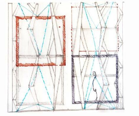
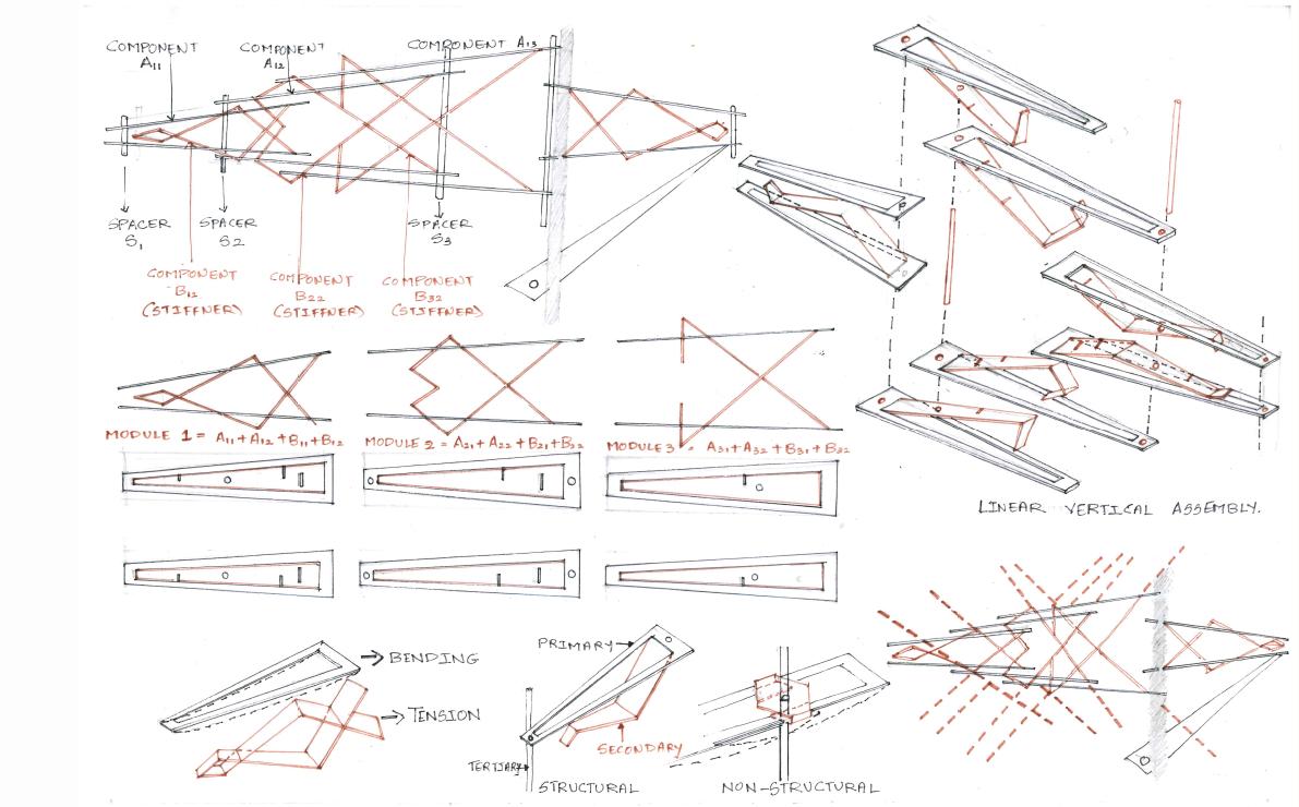
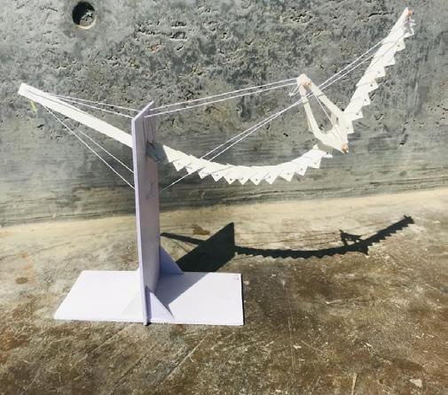
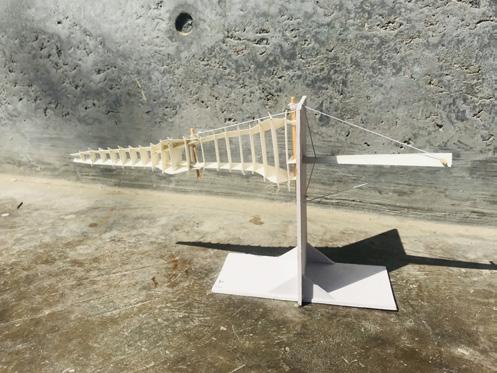
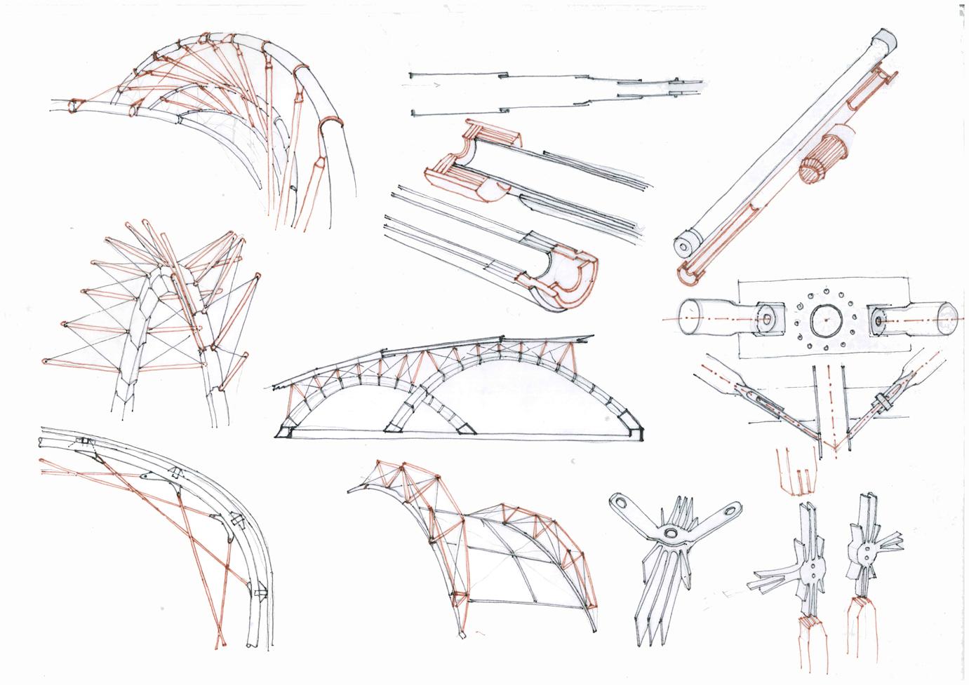
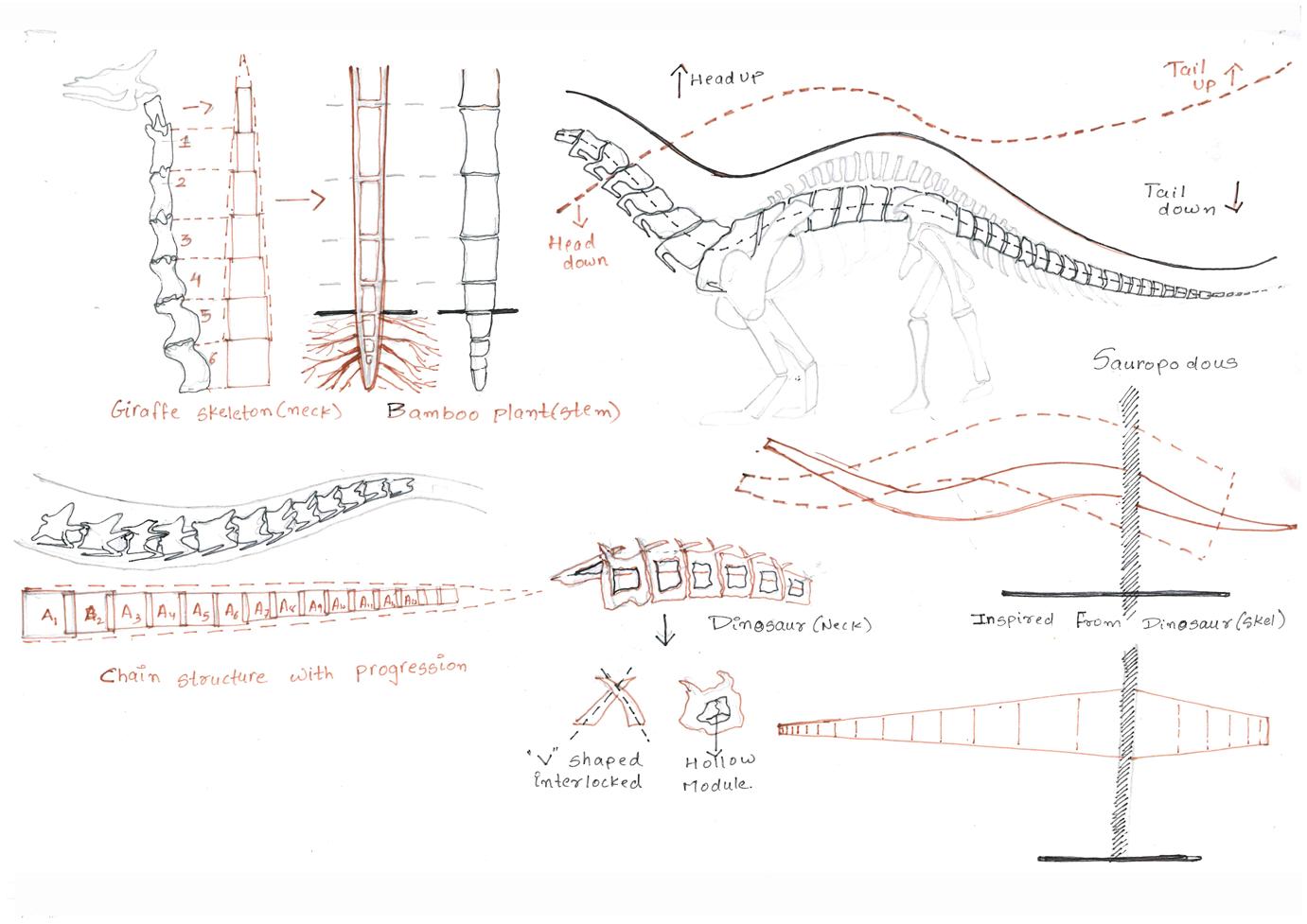
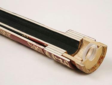
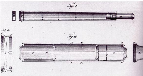
ANALYSIS OF SELECTED MODEL TO STUDY FORCES, KIT OF PARTS AND JUNCTIONS BETWEEN MODULES MASS AS OW FOR E SITE AND FUNCTION INSPIRATION FROM BRIDES AND ROOF STRUCTURES FOR CANTILEVER STRUCTURE AND STUYDIN ALELIOS TELESCOPE FOR STUYDIN JOINERY AND JUNCTION OF STRUCTURE W IC ARE REDUCIN WIT SIZE AND FORM MOVIN TOWARDS H OT ER END.
BAMBOO FOR SIZE VARIATION WITH PRORESSION. (CANTILEVER IN VERTICAL DIRECTION)
STA BY ADDIN SURFACES TO REDUCE TENSION LINES. LINEAR MEMBERS AS STRUCTURE USED FOR SUSPENDING MEZANNINE MODULES SIZING AND SCALIN EM ACCORDIN TO STRUCTURE AND EN MATERIAL REQUIREMENT. ROTATIN AND FLIPPIN EM TO DERIVE MODULE AND US JOINERY IN COMPONENTS SOULD BE SUC HAT EAC ALLOWS AN INDIVIDUAL MOVEMENT. ALL COMPONETS TO EATER AC IEVES EQUILIBRIUM.
MASS MODEL OWIN SAME AND SIMILAR KIT OF PART AND 3rd SIMILAR PART PLAYING ROLE OF FORMING OPAQUE AND POROUS VOLUMES.
STAGE 2 PROPAGATIN MODULE IN ALL 3 AXIS AND US SEEING SIZE AND FORM VARATIONS HEN ASSEMBLED A.MODULE USED VERTICALLY MODULE USE ORIZONTALLY A- VERTICALLY AS COMPRESSION MEMBER AND ADDIN FORM TO H PART OF A MODULE WIT HICKER CENTER AND HINNER ON SIDES TO AVOID BUCKLING B. EIT ER TENSION OR COMPRESSION MEMBERS.
FORM AND SIZE OF SIMILAR COMPONENTS AN IN ITSELF TO STRUCTURE FOR CANTILEVER WILE PRORESSIN BY PROVIDIN BRACIN AND HUS BECOMES A COMPONENT OF SIMILAR MODULES. STAG E 1 DERIVATION OF FORM FROM ELEVATION OF MASS MODEL AND REDUCIN IRD KIT OF PART WIT MEZZANINE LEVEL. SIZIN COMPONETS SIZES WERE TWO PARTS OF SIZES WORK AS BRACING FOR SUSPENDIN GEST SIZE MODULE.

1208.3
MATERIAL DIMENSIONS COMPONENT METAL COLUMN SUSPENSION OF ELIX TUBE MADE UP OF METAL PIPE BRACED WITH SPACERS. ARRAN EMENT OF HEXAON FORM IN VERTICAL (ASSEMBLY) MANNER AS SUPPORT.
FORM COMPONENT SIMILAR MODULES SIES SUC AT EY BRACE EAC OT ER TO MAKE A 3D SCREEN FOR FACADES ON TWO HORTER SIDES OF OP ALSO PLAYS ROLE OF MASK DISPLAY ELEMENT AND PARTIALLY SUPPORTS OPEN ENDS OF CANTILEVETR TUBE.
3227.65 2848.6 1331.05 1763.65 1476.89 1269.73
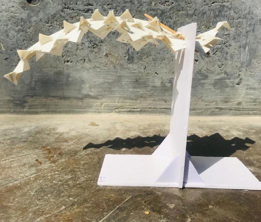
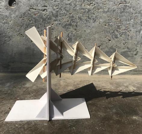
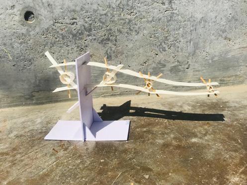
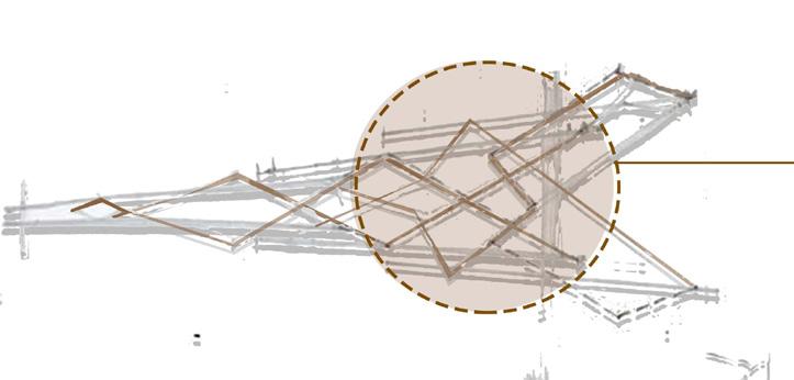
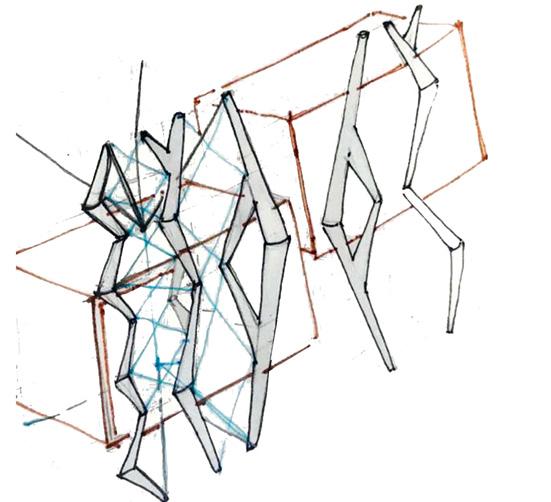
SHOP FOR MASK : FRAMENTED POROSITY INSPIRATION FORM NATURE FOR CANTILEVER STRUCTURE DESI N STRUCTURAL /SKELETONAL SYSTEM OF LOND NECK BIRDS AND ANIMALS. LEARNIN AND OVSERVIN HOW SMALL PARTS OF SIMILAR FORM BUT DIFFRENT SIZE INTERLOCK WIT EACH OT ER TO FORM FLEXIBLE BUT STABLE SYSTEM. R200
1208.97
1206.61
1210.1
3227.65 2848.6 1331.05 1763.65 1269.73
3227.65 2848.6 2689.34 1331.05 2153.62 1476.89 1269.73
681.92 R26.86 STRUCTURE COMPONENT COMPONENT ELIX TUBE SUSPENDED ROU METAL SUSPENDED STAIRCASE ROU H METAL COLUMN COLUMNS CUTTIN LON ITUDINAL DIRECTION STRINER ELIX BEAM SUPPORTING ELIX OF SPACES ARRANEMENT OF EXAON FORM IN TUBE ELIX TUBE ORIZONATAL (ASSEMBLY MANNER AS CANTILEVER TUBE.
1210.8 1287.01 730.75
787.7
677.58
1323.26
METAL FLAT SPACER
R10.36 R8 28.61 R50.39
159.98 R60
1323.26
1207.53 1209.08 1094.53
METAL PIPE SPACER
1196.02 1239.39

1323.26
SPACER SPACER METAL FLAT METAL PIPE
R200
111.45 R10.36 11.54 28.61
159.98 R60
11131.28 1304.27 1250.68 1322.27 1264.3 1242.67 1294.37 R8.08 R8.08
R200
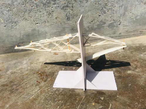
CANTILEVER STRUCTURE DESI N INSPIRED FORM NATURE AND MAN MADE OBJECT (LONG NECK ANIMALS AND GALELIOS TELESCOPE) SIDE ELEVATION PLAN DETAILS
749.68 CEPT UNIVERSITY IR - 3009 --- XYZ OF ABC DEVANSHI PATEL UI4915

159.98 111.45 R10.36 11.54 28.61
METAL
Introduction to Studio:
• The studio focuses on ‘design’ role of technology in the field and practice of interior design.
• To set up an exploratory attitude to the program with emphasis on interior design-space as an outcome of relationship between technology and expression.
• The possibility of serving and practicing design knowledge needs systematic and structured explorations to resolve modes of technologies in construction of enclosed interior spaces where interior elements are agents of feasibility of assembly based construction and its technology.
• This studio also synthesizes technological changes in solving interior design field problems.
Brief Outline:
The studio is seen as an experiment between making of interior elements, organization of interior elements and modes of technologies in resolving assembly based construction of enclosed spaces.
The studio also relates initial hands-on workshop outcomes to apply them to different contextual situations and occupational patterns.
The course will formulate, resolve and apply assembly based construction as different approaches in the current practice of interior design.
Students will use multiple design abilities developed from resolving constraints of assembly based construction and apply as approaches in concertizing interior design projects which will be critically evaluated to specific relationship between site and program.
Learning Outcomes:
Students will learn to develop and explore ABC through abstraction and experimentation.
Students will learn to develop an experimental attitude to resolve and apply problem solving methods for given constraints of assembly based construction.
Students will learn to test and resolve technique of assembly based construction for necessary design development and its conceptualisation.
Students will learn to formulate strategy to adapt and tackle challenges within the interior design parameters and constraints of assembly based construction of design project (Site and program).
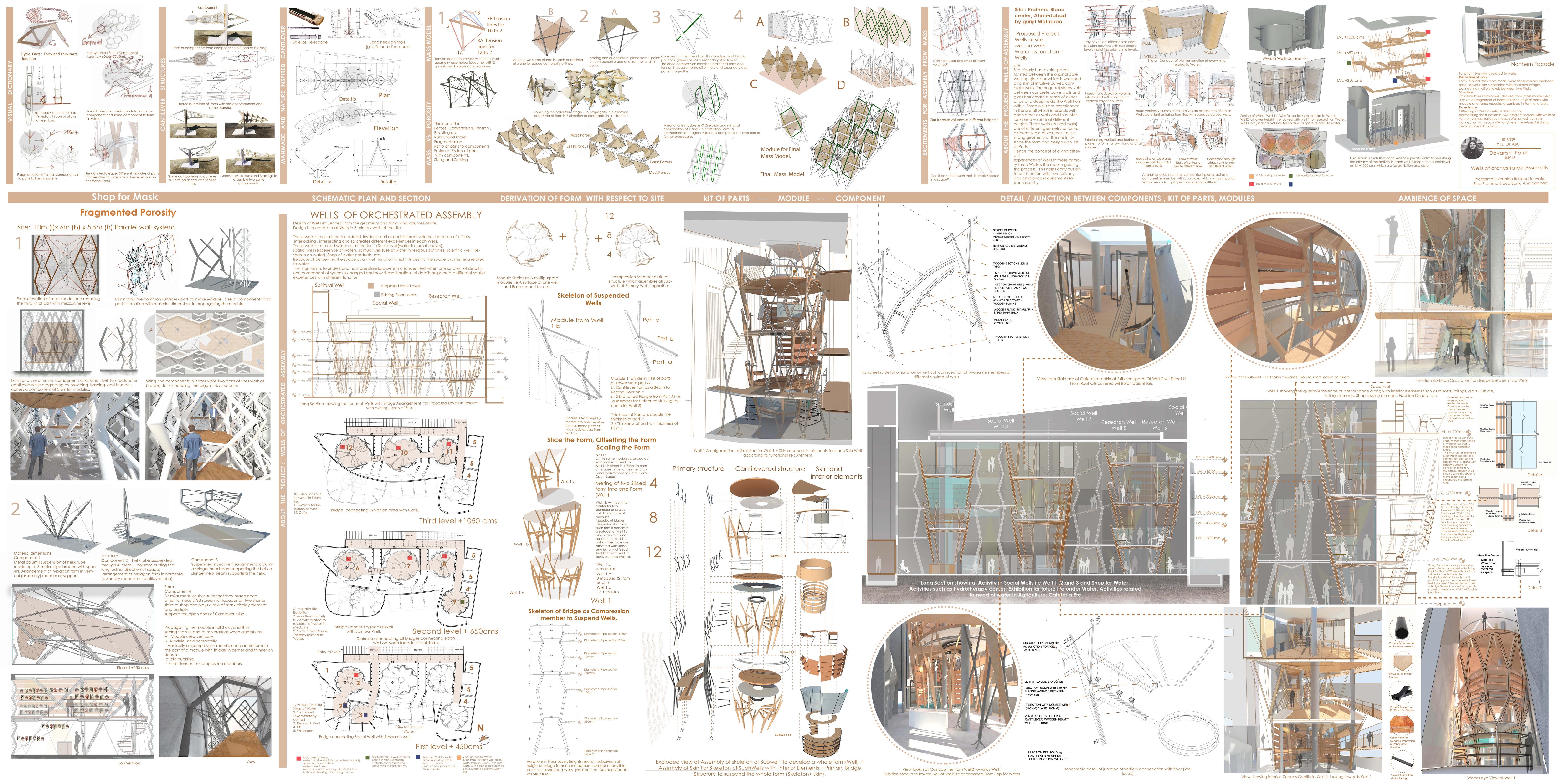
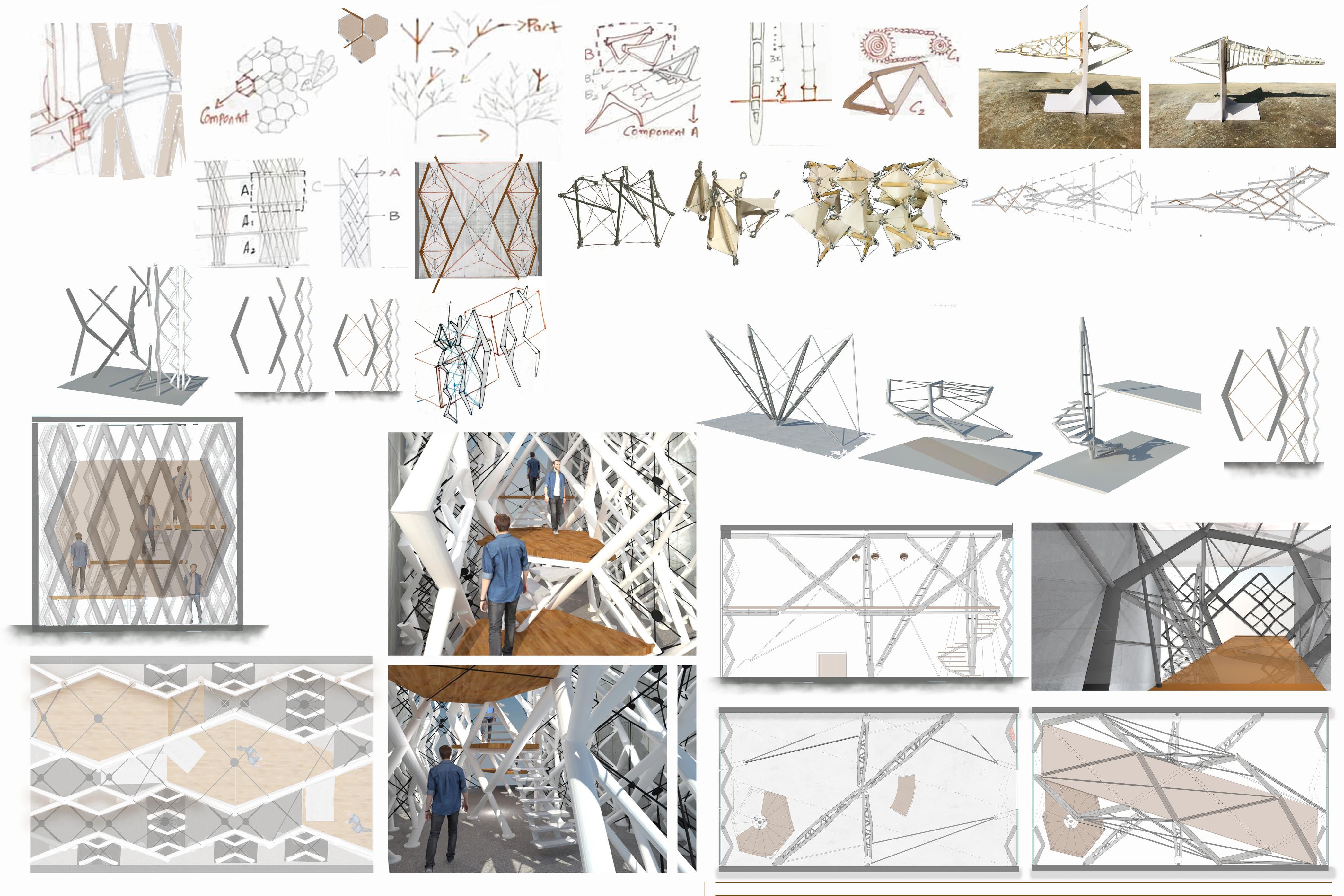
Borrowing from the principles which nature inherits such as thick thin, combination of materials, hierarchy, branching, forms , structure resulted into a process of derivation a form which are structurally stable in relation with the experience of space. This form finding resulted in iterations junctions of details from mass model which changes the geometry of form and thus the experience of the space with each changing detail . So process results in permutations and combinations of iterations of details to pick and choose the detail which best fits with site and its experience in it.
Project:
This project is the attempt to learn the answer to question such as
A: role and Ratio of kit of parts and components ratio?
B. Role of material optimization of kit of parts available to design a stable and ephemeral structure?
D. Is an assembly based system a fusion or fission of components?
Kit of parts are different modules which can be iterated to form different system consisting of same, similar modules wit different structure with different role given to each part of a system.
Mass model is developed looking at mass vs porosity ratio as 30-70 and understanding the role of primary and secondary members making a module in order to derive a stable system. (ref 12 to 14)
This derived form and shape and structure of module is considered as a part of a system in shop which is further propagated , scales , sized in all 3 axis such that it forms a stable system and also guided in designing interior elements such as staircase, display element for mask, mezzanine, entry etc. (ref 15,16)
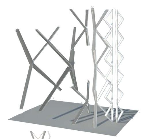
The further developed mass module wit sizes and shape from the shop is now reflected in final project site i.e Prathma blood center, Ahmadabad to fulfill function for everything related to water. Prathma blood bank as 4 volumes in which 3 from curved walls and one is the cuboidal volume enclosed by curved walls leaving void in center as well for lit.tis hue curved walls on south facade are looked as a volume similar to wells. (ref 18)
The function of everything related to water resulted in spaces with different experiential quality because of spaces related to exhibition(mostly crowded), shop for water( most used), hydrotherapy (most private), activities related to water (private for approachable) resulted in dividing the spaces in levels such that privacy is maintained in each space dentin a boundary with a closed surface. (ref 20,21)
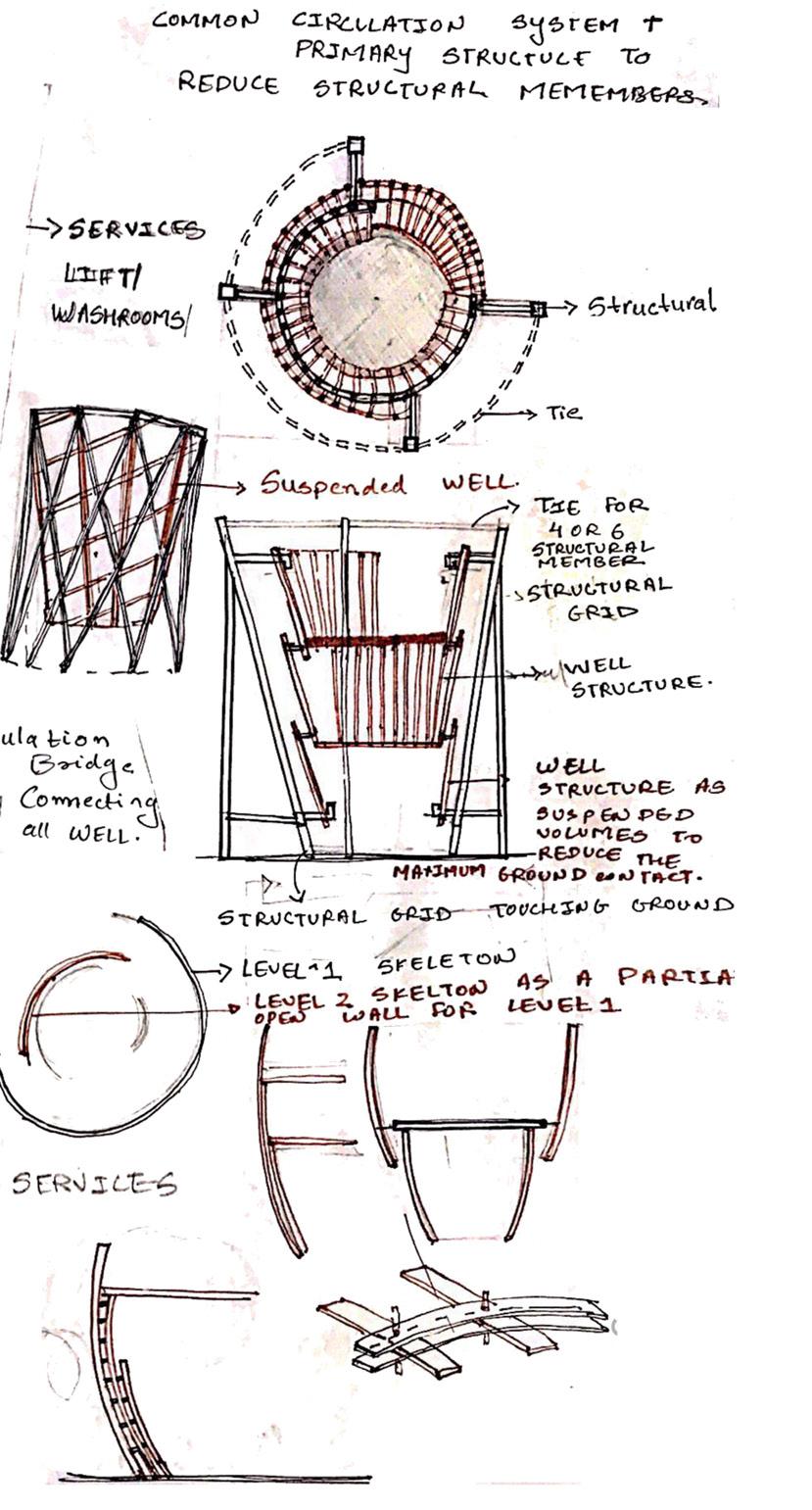
Considering mass model made up of primary Skelton as form deriving grid, secondary structure as supporting primary grid and surfaces as tertiary grid is reflected upon in project. Design approach to create a form were module can propagate vertically and derive sub forms(wells) inside a primary form(well) along with giving individual character to each form by twisting, rotating, offsetting, scaling the module and thus the forms and thus studying role of kit of parts change with change in experience of space. (ref 22,23)
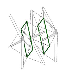
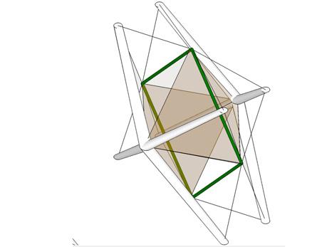
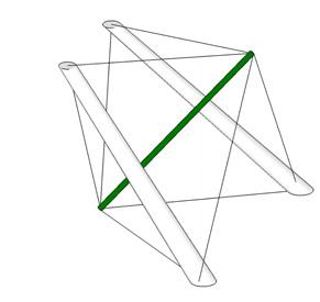
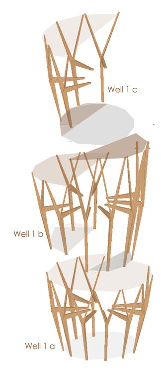
Primary module (skeleton of wells ) are scaled, rotated , twisted, offseted to created quality of spaces the function demands.(exhibition : open , hue, approachable so module used are scaled to achieve double either interlocking with the ,module creating single height space on 2nd level.)
Final mass model
Module of Kit of Parts from Shop
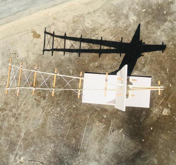
Module for Skeleton of Suspended Wells Module for Bridge Structure.
Exercise Brief & Attempt:
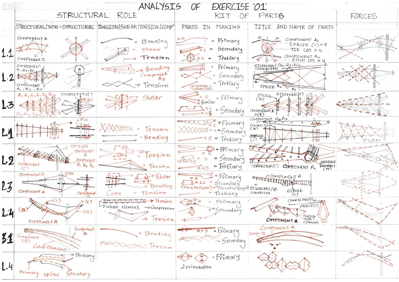
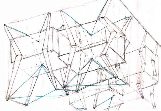
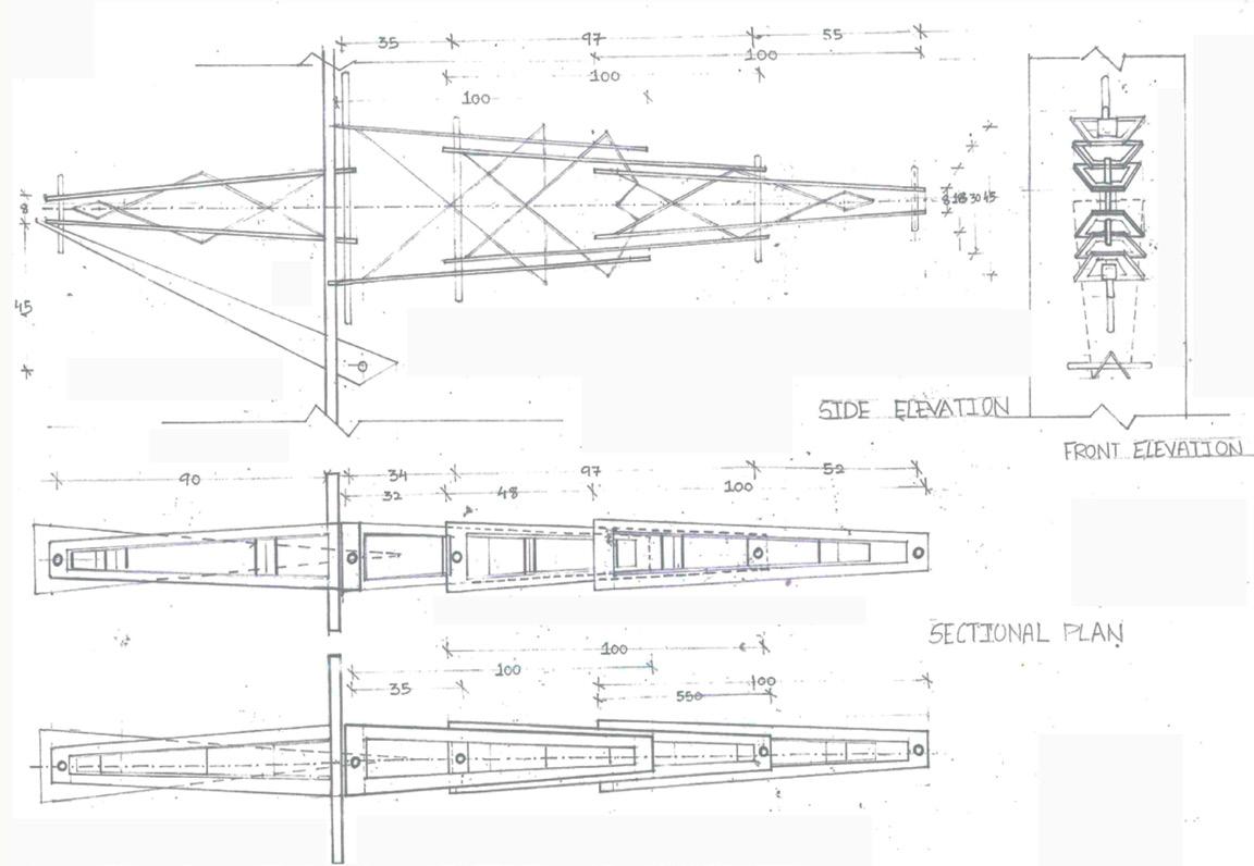
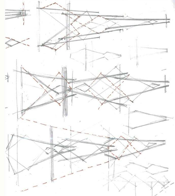
Analyzing and studying the forces diagram for bending , torsion, shear and compression and understanding the role of each part given in designing the system such as stringer, stud, connector, bracing etc.
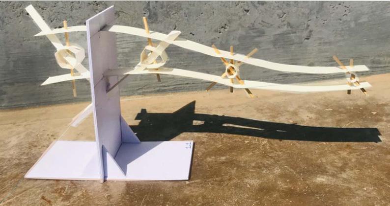
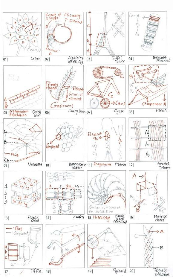
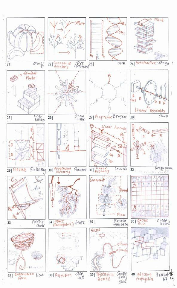
Also studying the kit of part and component of the system weather they are progressive, propagative or repetitive or staggered etc. Same Kit of parts to achieve a particular form with assembly of modules inspired from visual dictionary of nature and man made objects which are structually stable with use of accessories such as studs, connector, spacer , stringer etc
Learning Outcomes:
Form and Shape of Structure is very important part in order for a structure to be stable. Shaping the Kit of part should be such that it gives Form to the structure along with stability keeping in mind the material optimization. The role of same kit of part for making same, similar and different component to assemble a structually stable System.
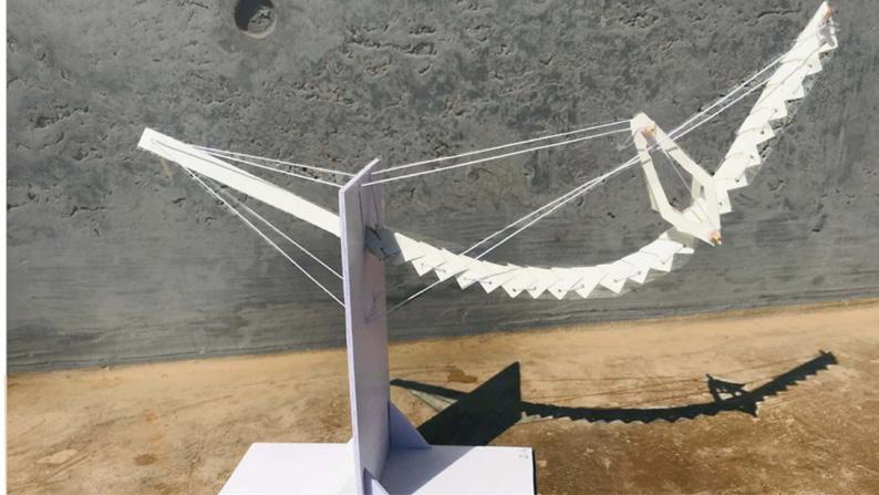
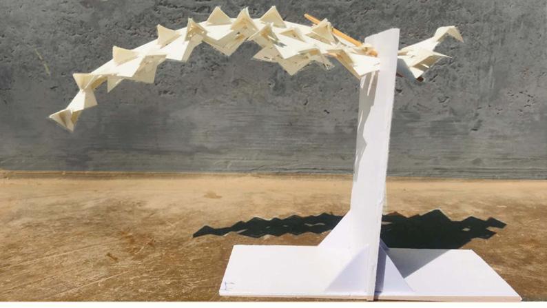
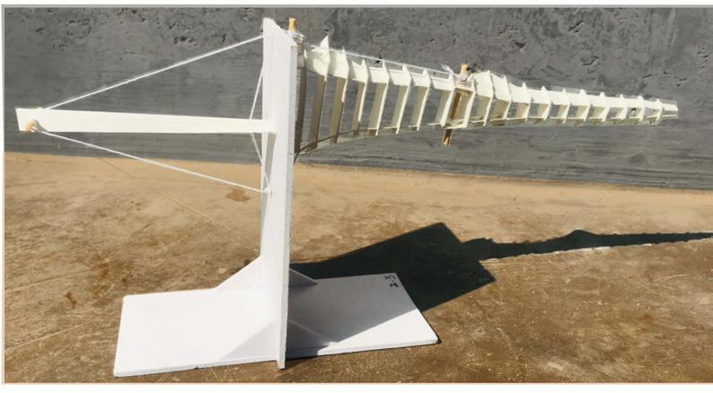
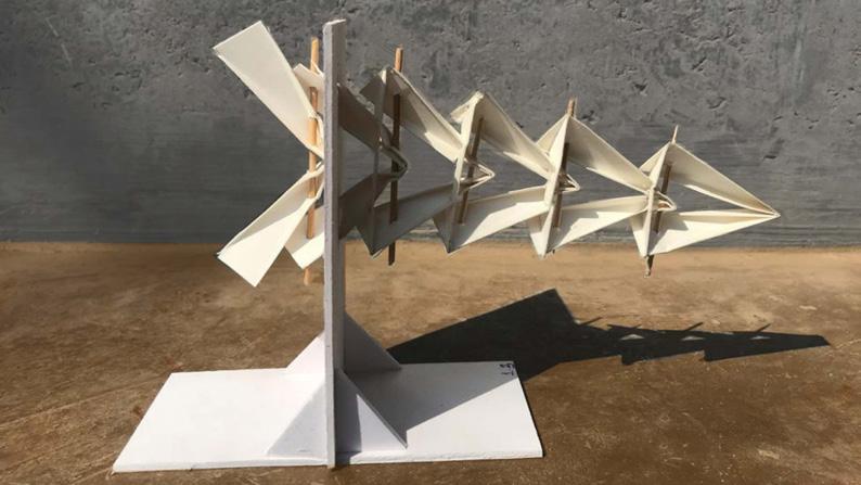
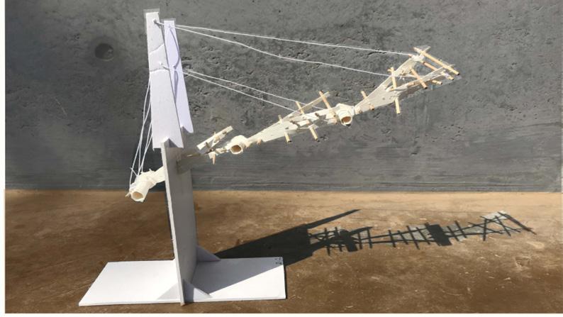
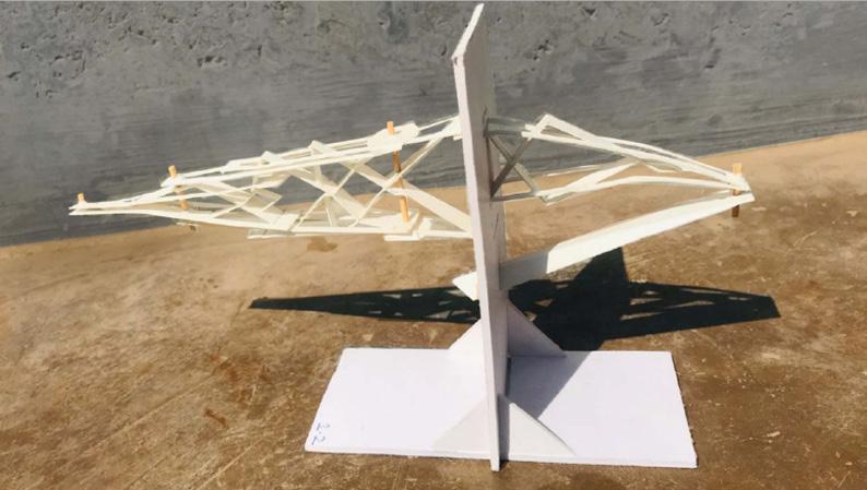
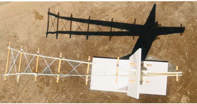
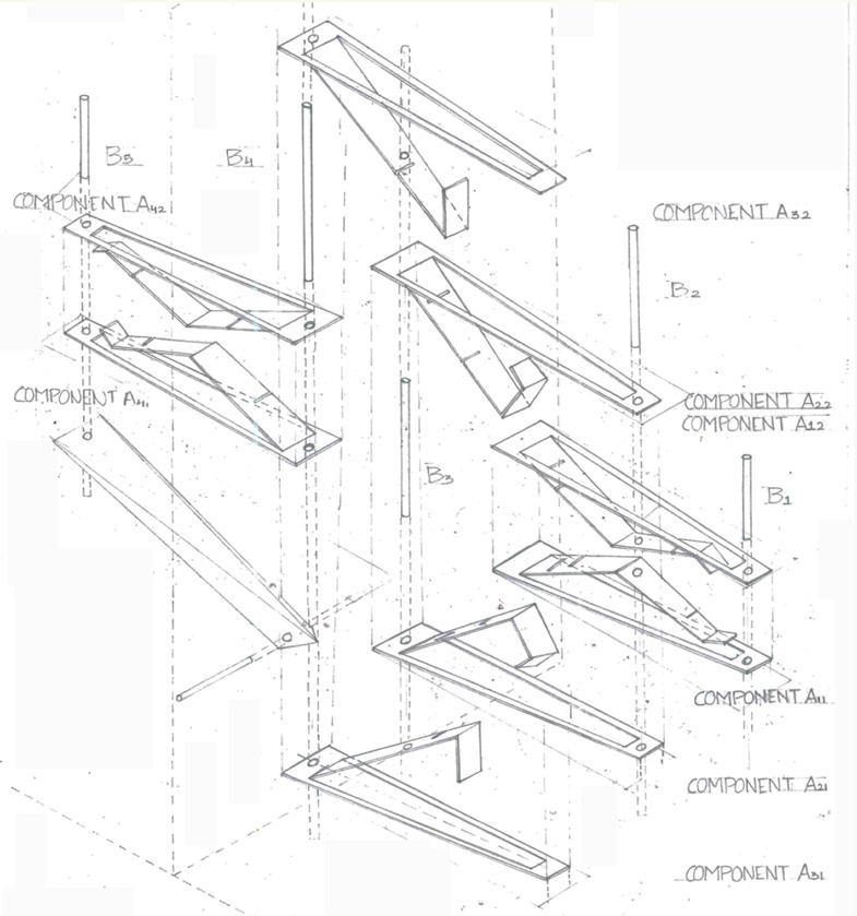
Analysis of Cantilever Models


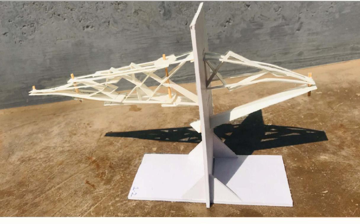
Analysis of Model 1.2
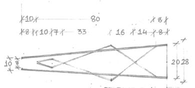
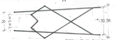
Role of Structural components Kit of parts
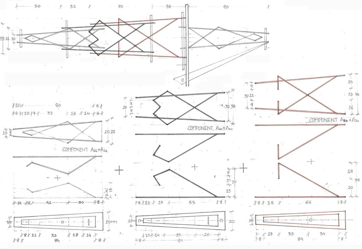


Mass 02
Exercise Brief & Attempt:
10mx 6m x 5.5m of mass tray in the selected material with a specific density, volume and weight. Explore in it terms of the construction techniques of the mass with respect to its tools following a method of rule making and evaluating the obtained weight vs density ratios to observe and analyze composition of mass and porosity. The connection here states the articulation of opacity within the developed assembled mass to achieve porosity.
5 different explorations of mass model with cross section of these materials (i.e planar, linear, )with order based rules of construction.
Learning Outcomes:
The developed mass shows the property of construction with real material to elasticity, tension, bending, cutting, interlocking etc. The resultant mass inherits the understanding of structure from cantilever model and nature inspired Assembly Based Construction such as Branching , Progression, Propagation, Thick to Thin, Solid to Hollow etc. Making the itteration of the details and junctions of mass model helps to analyze the other options to see a component in linear, planar ways and further develop 5 other options with same component and kit of parts and thus to explore different property of same materials.
1 2 2a 2b 3
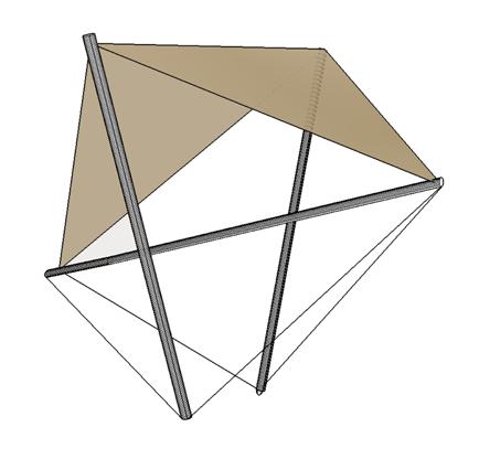
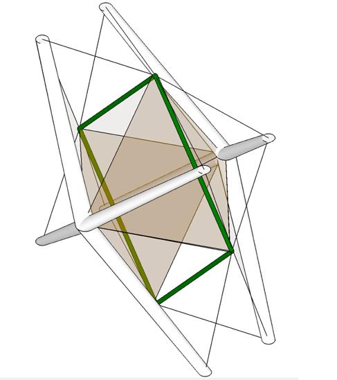
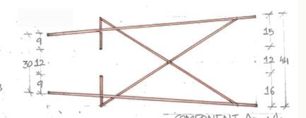
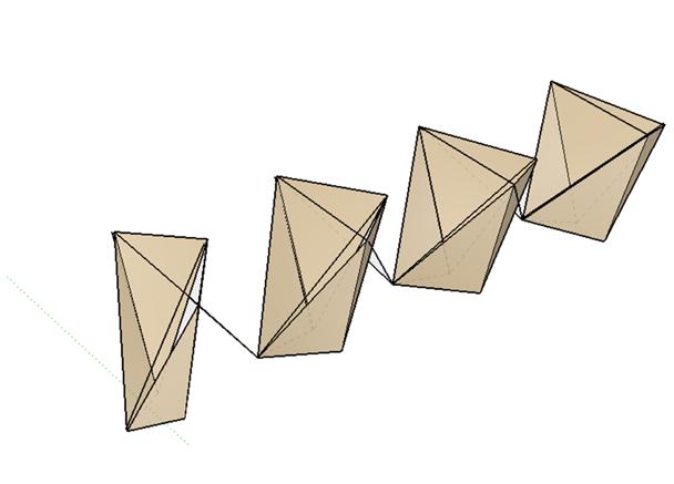
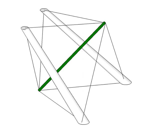
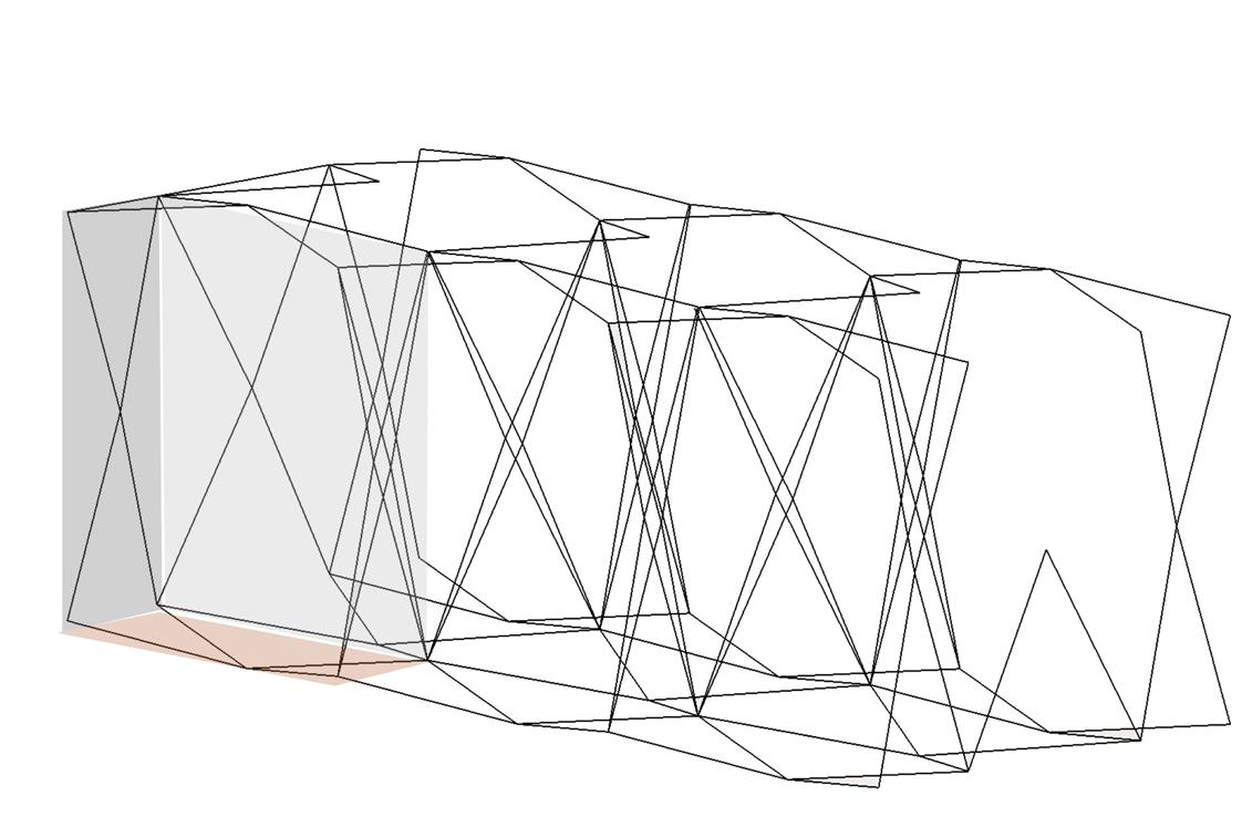
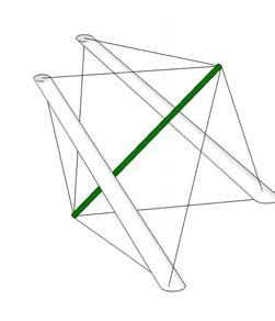
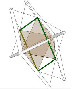
Tension and compression with three struds geometry assembled togeather with 2 quadrilateral planes as tension lines.
Adding planes to reduce complexity of line and to play with 70% mass and 30% porosity ratio.
Adding 2 Quadrilateral planes connecting two end of one different component to with edges of two same component.
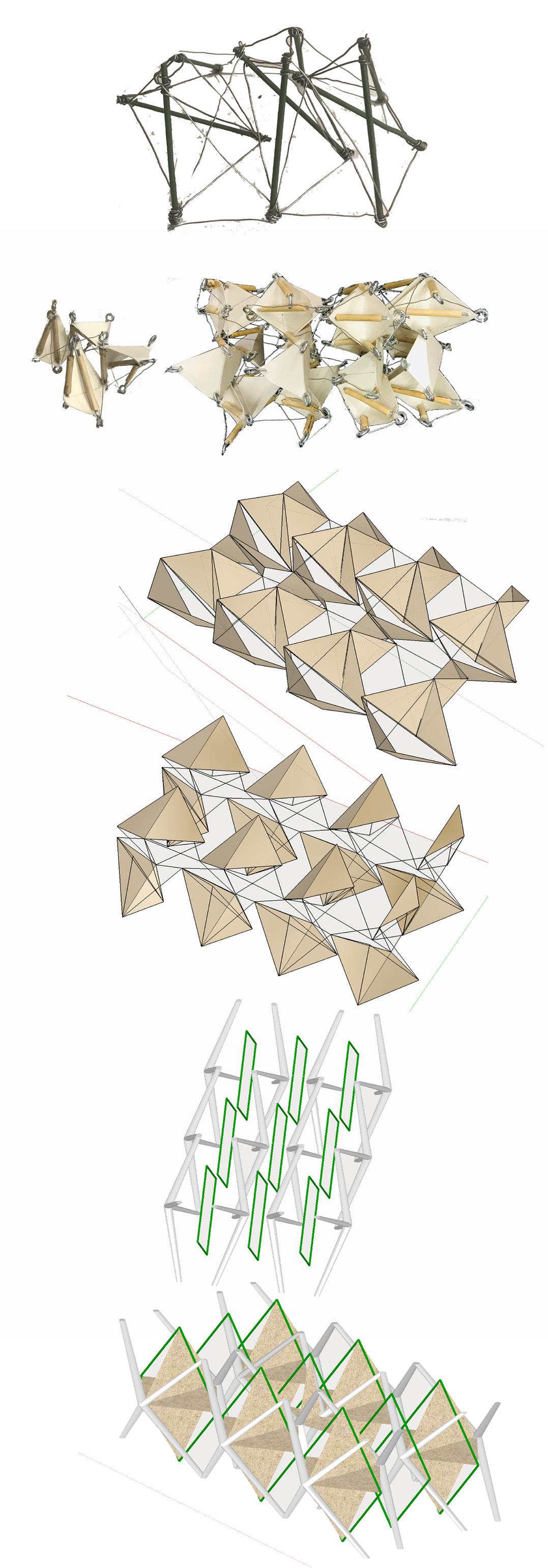
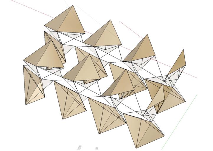
Adding one quadrilateral plane such that it connects one end of two same components with edges of one different component.
(Stage 3 to develop along with Shop for Mask).
Adding real material scale Junctions thick to edges thin.
(Stage 4 developed after Shop for Mask).
Along with rotating and mirroring the module ,adding planes to reduce complexity with same rule based order as in Stage 2b.
Development stages of Mass Model
Adding two same planes in each quadrilateral plane to reduce complexity of lines.
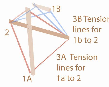
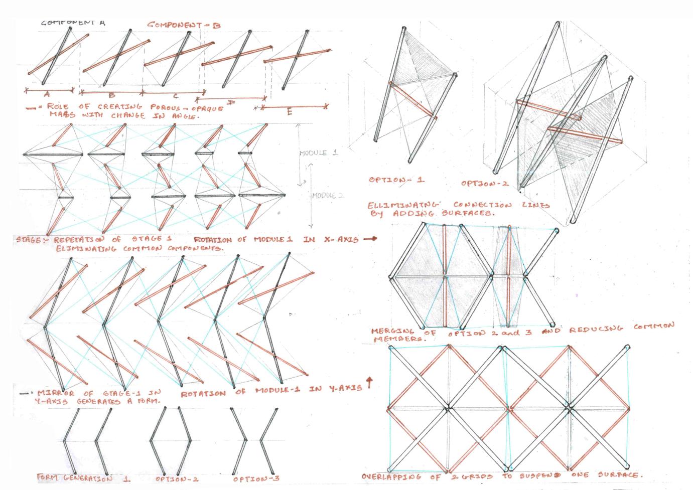
Component 2 as a primary element responsible for changing the Form by rotating it from centroid of component from -45 to +45 degree.
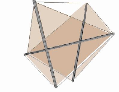
Adding one quadrilateral plane from 2 points on component 2 and one from 1A and 1B each.
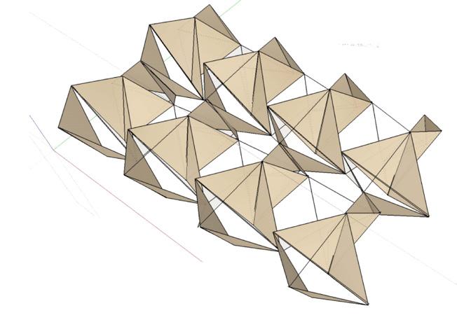
Propagate in X direction and Mirror of form in Z direction to propagate in -- Y direction .


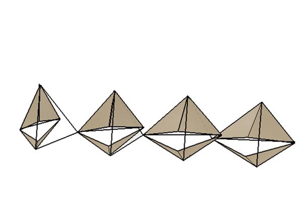
Modue 1 which is rotated 180 degree such that component 1b becomes a common component for both module which is then repeated in X-Direction.
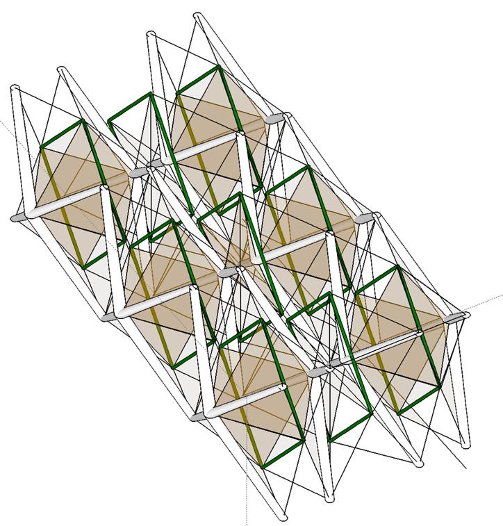
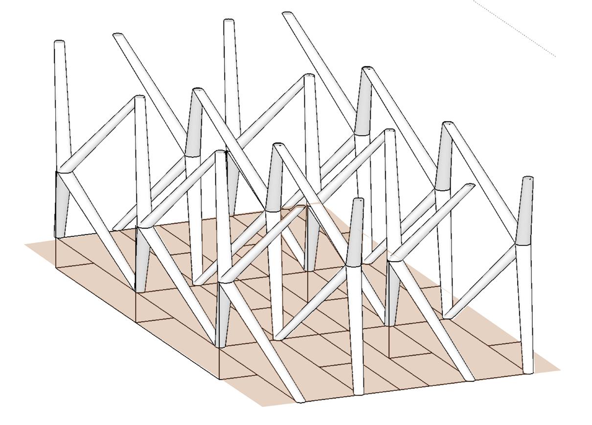
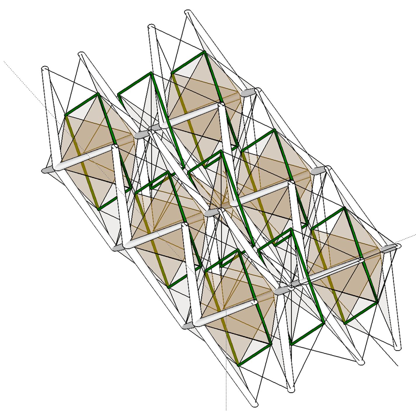
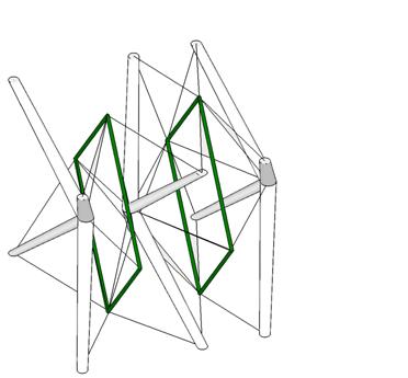
Compression members from thin to edges and thick at junctions. green lines as a secondary structure to balance compression member retain their form.
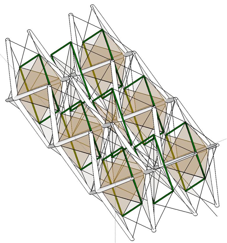
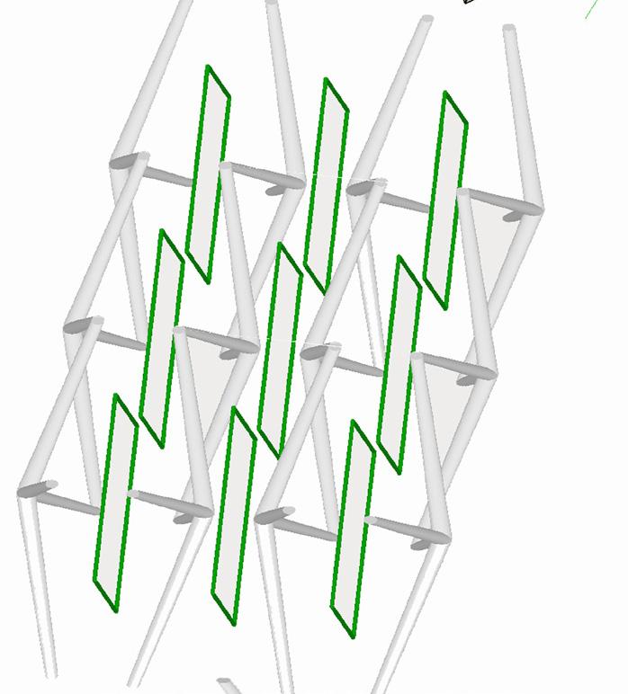
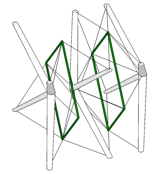
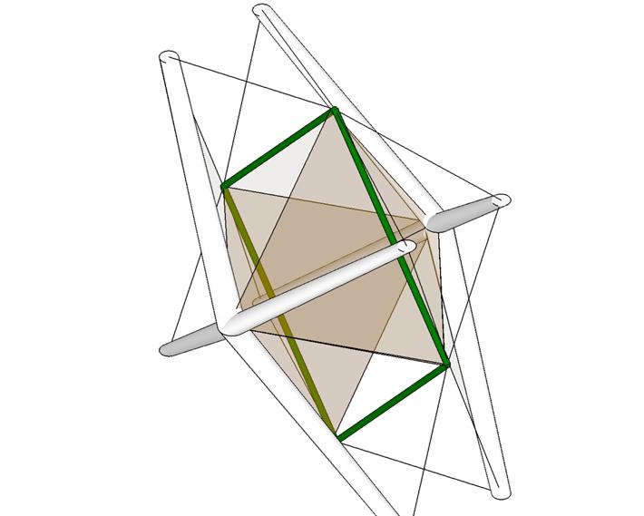
Mirror of one module in - X Direction and mirror of combination of + and - in Z direction Forms a component and again mirror of 4 componet in Y direction to further propagate.
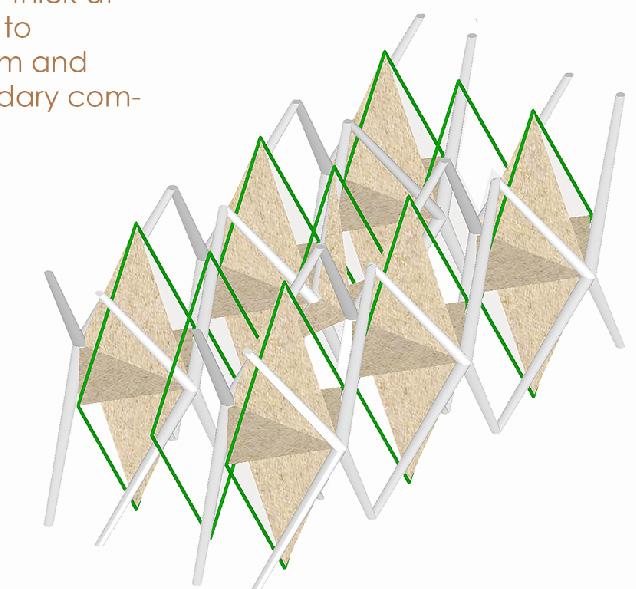
Primary grid of components i.e White components to derive a form and green elements as secondary elements to hold the assemble two white mirrored trays of white components together.
Adding a layer of tertiary grid i.e planar surface as suspended elements to tie green and white rid with tension lines and stabilize the primary Form.

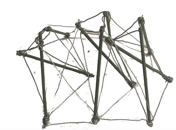
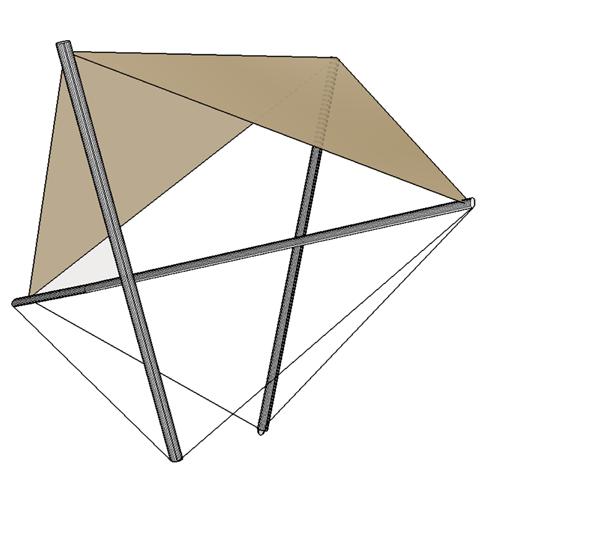
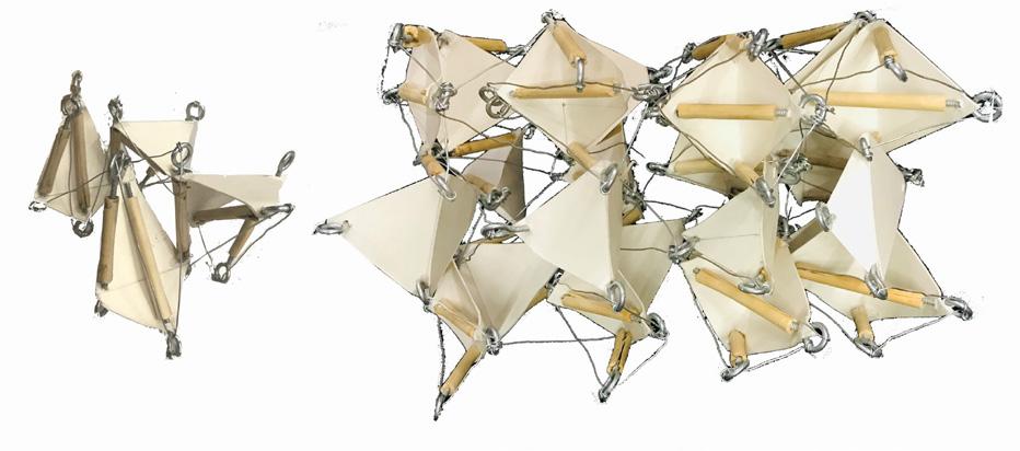
Tension lines to hold on frame 1,2 and 3 with each other . This Frame behaves as a final tie connector and a system would collapse if one member from this frame is removed.
Suspended Volumes
Planar surfaces following the rule based order as in stage 2b with connecting of one quadrilateral plane such that it connects one end of two same components with edges of one different component. This Frame helps retain the from achieved by frame 1 and also holds Frame 1 with Frame 2. Final Mass Model
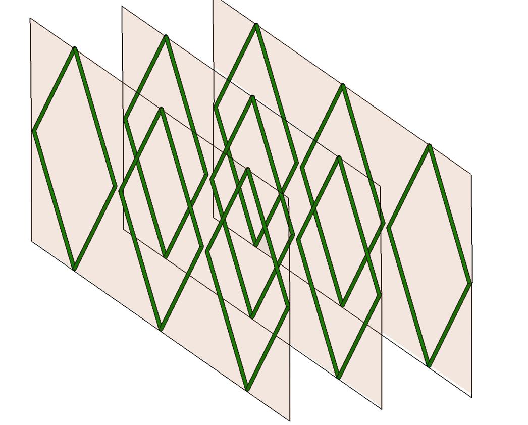
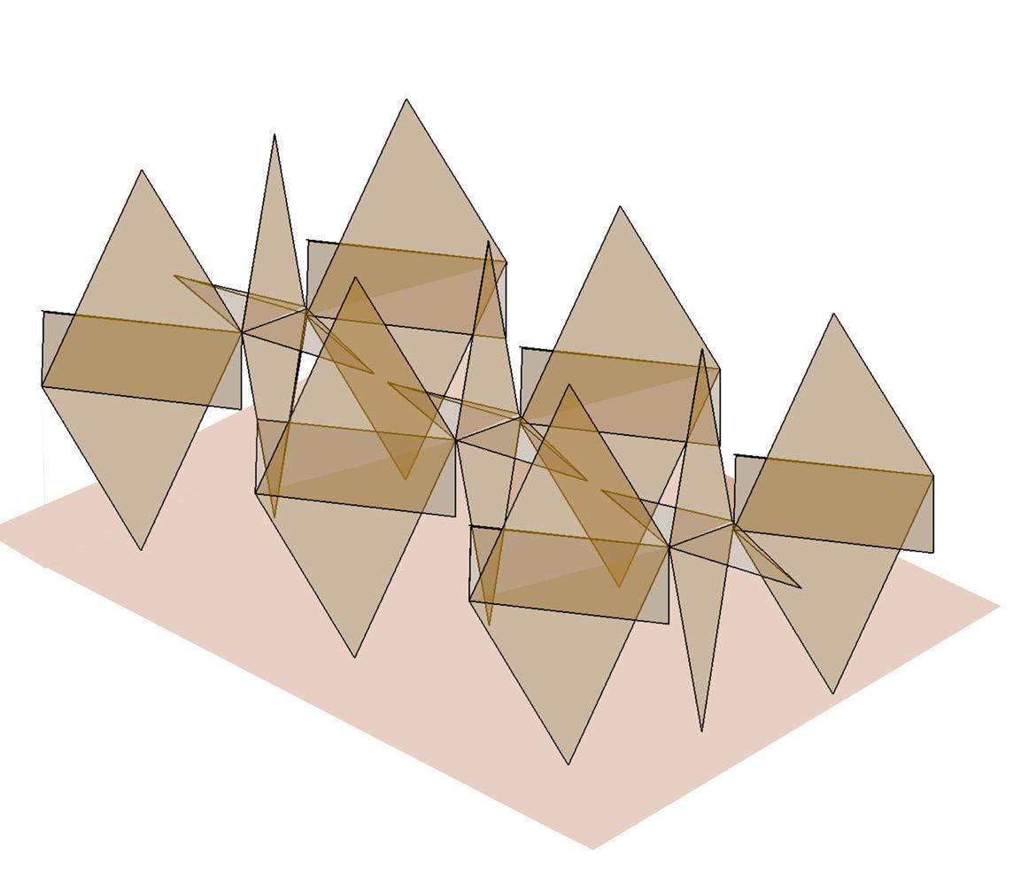
3 Basic components in making a system
a. White members as Compression members b. green as secondary frame to connect white members and
c. Surface planes (suspended) to connect green and white members
d. As tension lines assembling all 3 components.
Adding planes in rule order as in stage 2A . Rule order of stage 2 and stage 3 such that 2 compression members , one secondary plane in form of lines between two compression elements .
Tertiary elements as skin for assembling Primary and Secondary Elements togeather .
White members as skeleton to generate a Form. green gives stability as bracing between compression members.
Planes as primary element to assemble skeleton and bracing.
Frame
Responsible for Changing Form
Secondary rid as a Closed Form which supports Modules individually and not as a grid . This Plane of Linear elements behave as grid to helps Assemble two grids of Frame 1 together.
Compression Members
Primary grid of Elements responsible for giving a Form to the System. Playing with thick and thin sizes such that Components becomes thick at junctions and thin at edges and are propagated in Z - Direction i.e size of cross section of components reduces while propagating them in Z direction .
Fragmented Porosity
Shop for Mask 03
Exercise Brief & Attempt:
Site: 10m (l)x 6m (b) x 5.5m (h)
Parallel wall system.
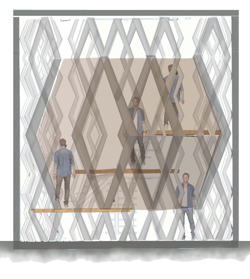
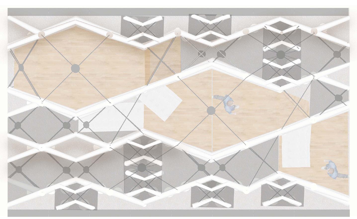
Understanding Form, Structure, Role of Kit of part, Module from the mass model which is transformed as a concept in architectural space with Parallel Wall system into Interior Space with a function of Shop For Mask.
Shaping , Scaling the modules from Mass Models in an interior scale to be used as a structural system with 50% mezzanine area, Interior shop display elements, Partitions, space dividers, Staircase, Entry etc.
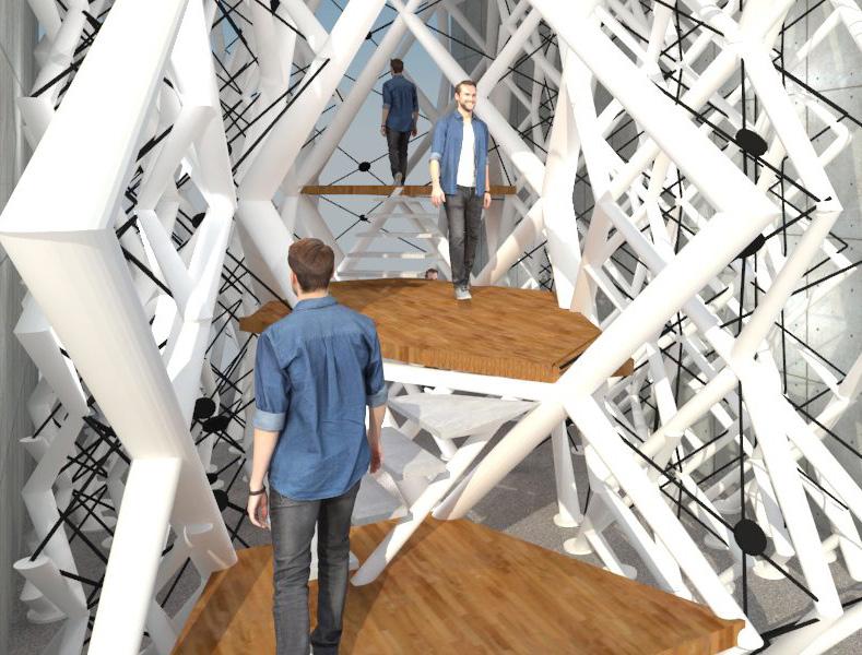
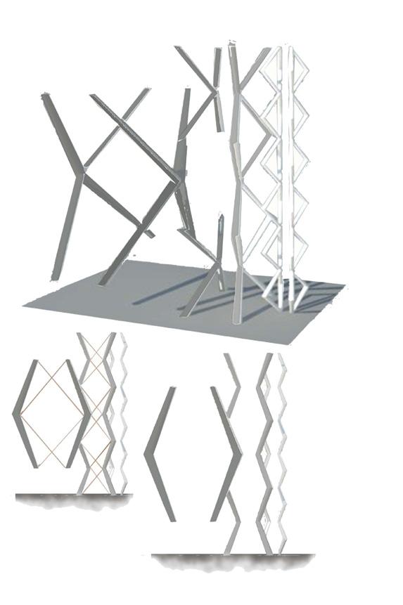
Learning Outcomes:
Role of Kit of parts and junction details with each kit of part to form a component is very important because a small iteration in a detail in an open System results in Change in the Form, Shape and Structure of the entire System.
While scaling and shaping a single module ,change in a scale of one single frame results in changing the whole System and results in an open system which is flexible or transform , which can assemble itself again to some different spaces with different function.
Material Dimensions and Junctions
Rotating , Mirrior of same module to form a component
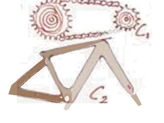
Simliar modules different form.
Fragmentation
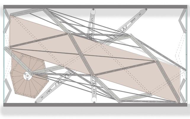
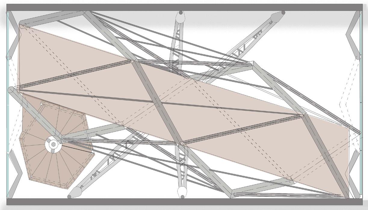
Plan at + 350 cms
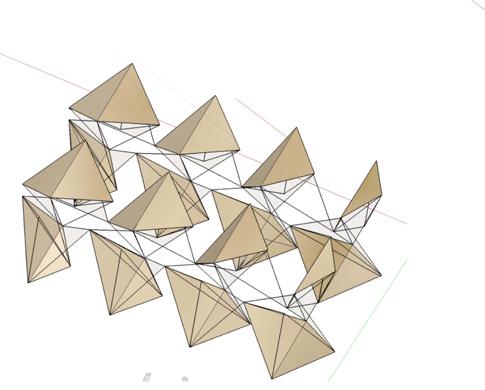
Propagation
Component 1
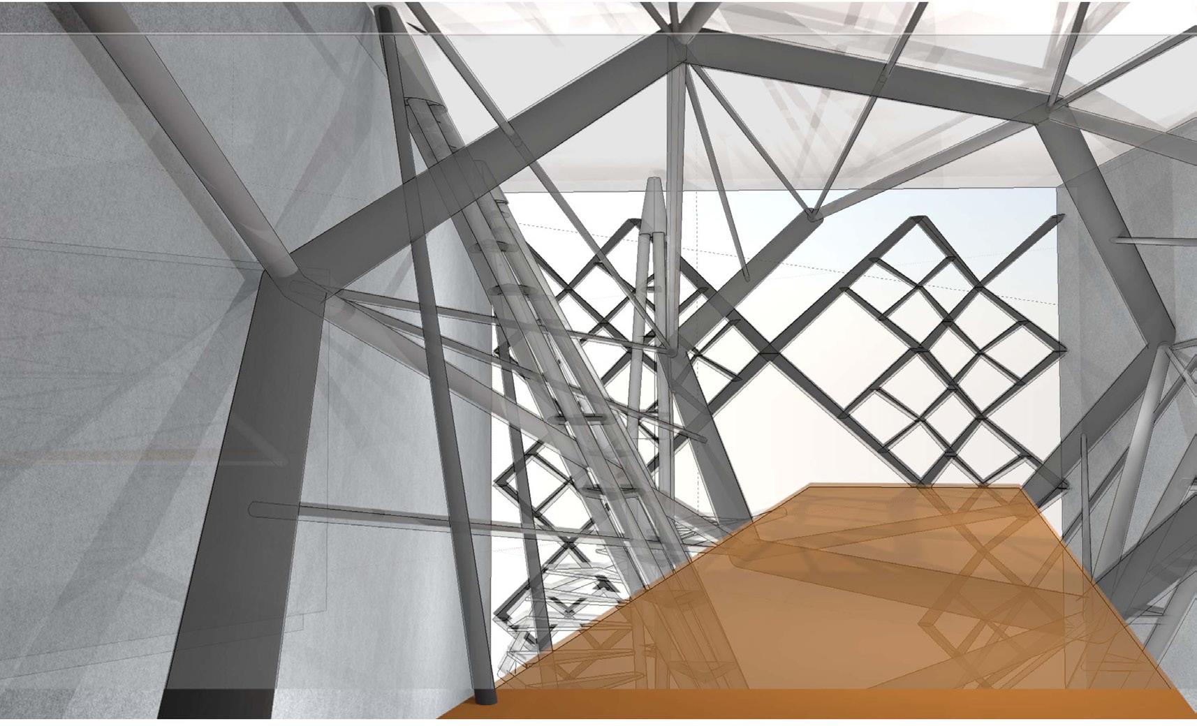
Metal column suspension of helix tube made up of 3 metal pipe braced with spacers. Arrangement of hexgaon form in vertical (assembly) manner as support.
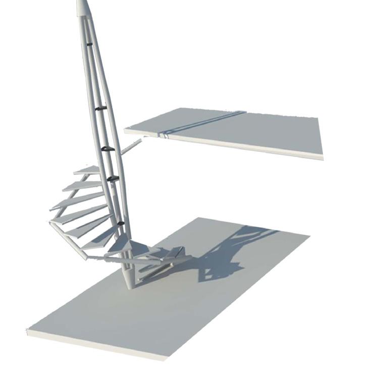
Component 2
Component 3
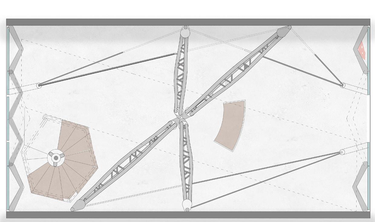
helix tube suspended through 4 metal suspended staircase through columns cutting the longitudinal direction metal column a stringer helix of spaces arrangement of hexagon form in beam supporting the helix horizontal (assembly manner as cantilever tube the helix tube tube.
Helix Tube
Assembled with a skin of Wooden Planks To design an ambience of a Tunnel Mask Display on Wooden Plank
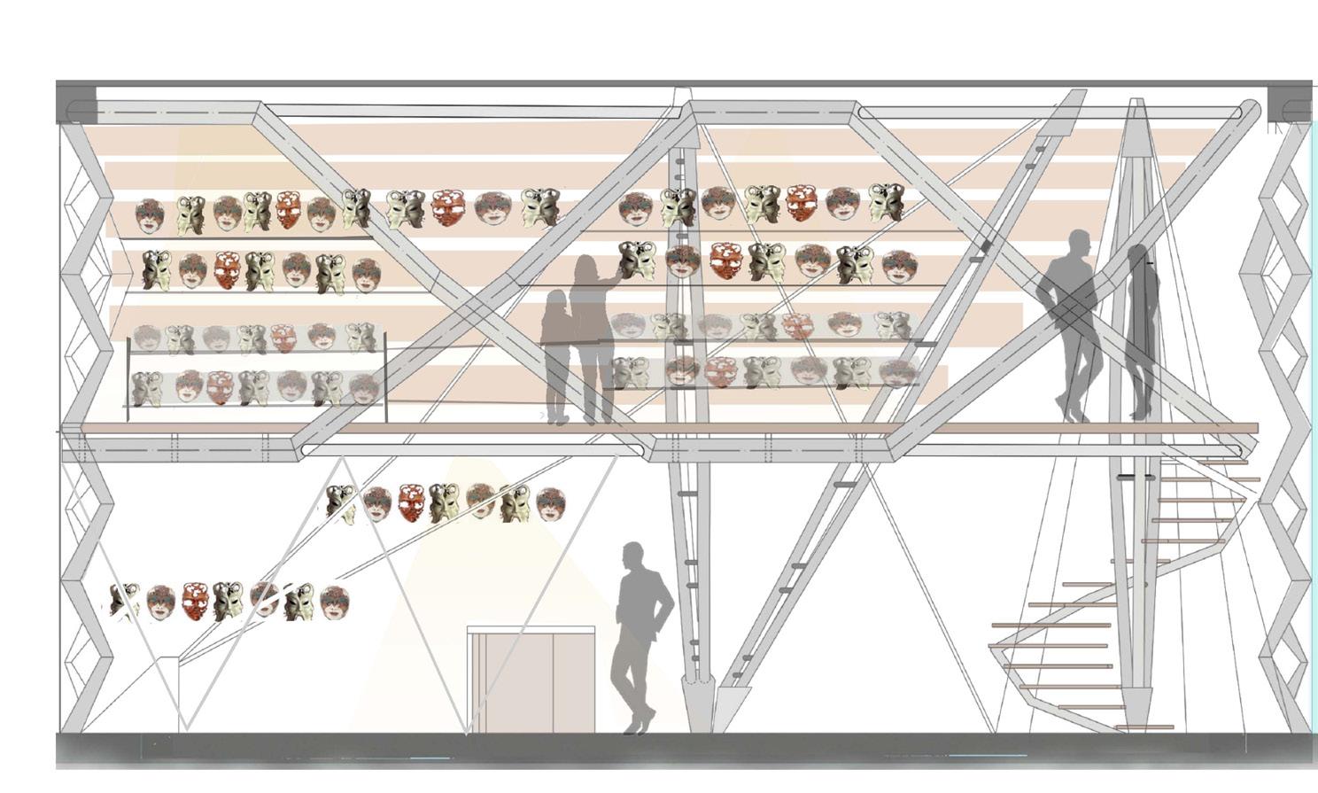
Mirror on Lower hemisphere to perceive helix Tube as Tunnel of mask
Suspended Spiral Staircase as Access to Tunnel.
Long Elevation
Elevation showing helix Tube suspended with 3 Metal pipe braced column helix Tube as a Display Surface for Mask of top hemispere of a tube and half with mirror reflecting the top dispaly so resulting into a tunnel filled with Mask.
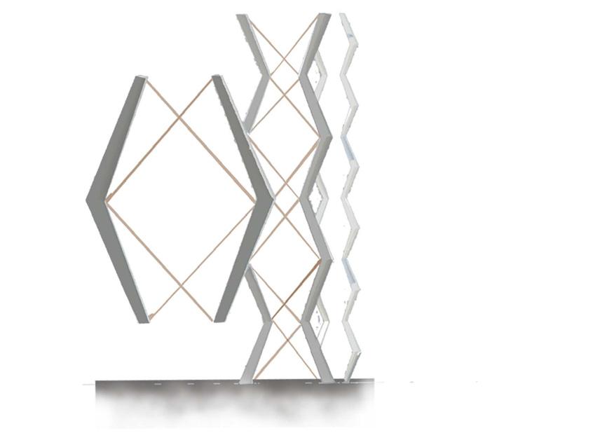
Component 4 3 similar modules sizes such that they brace each other to make a 3d screen for facades on two shorter sides of shop also plays a role of mask display element and partially supports the open ends of cantilever tube.
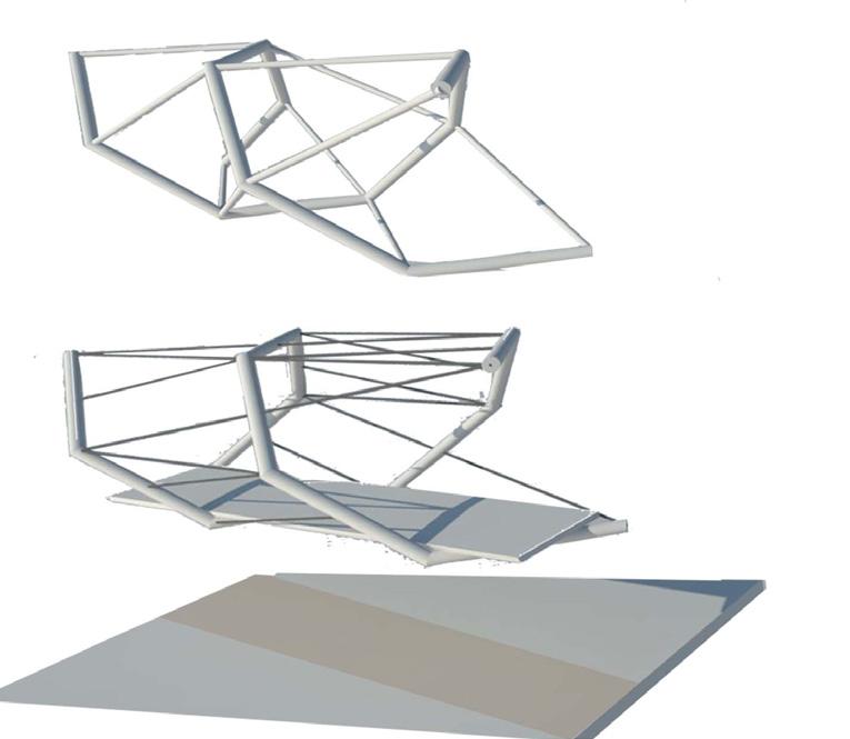
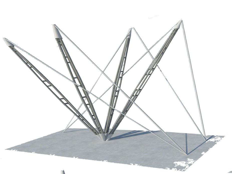
plan showing helix tube cutting a space along a diagonal lonutidinal axis of a cuboidal space.
Plan at+ 450 cms
Detail a Sowin Junction o between 4 similar members were brancin of Components
Plan at+ 200 cms
Detail b Showing the detail between the compression and tension Member in helix Tube.
Details
Process Flow Chart
The process can be classified under criterions of understanding of assembly from nature and in manmade worldwide works of famous designers and develop an understanding of Structure stability with understanding of principles of nature (Branching, progression, propagation, repetition , thick to thin etc). Deriving a form and geometry were junctions between two components can iterate to develop and new system. Structure and construction depends on the Form and geometry derived to construct a stable system. Creating unique experience and ambience by playing with the forms derived from Iterations of junction details. Adding functional requirement adds to a more precise detail.
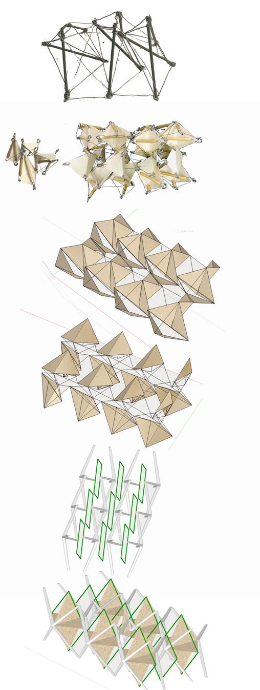
Detail Ambience and Experience
Structure Form and eometry Structure and construction.

Mass Model Site Excitement (A)
Site Excitement (B)
Stage 1 For Shop For Mask
Visual Dictionary Cantilever Structures Mass VS Porosity


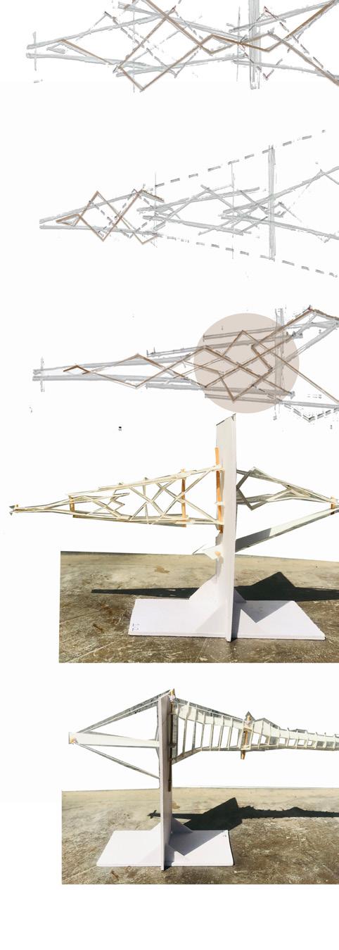


Mass model to Shop for Mask stage 1
Mass model to Shop for Mask stage 2
Stage 2 For Final Project
Site Excitement (C) Theory site+ function+ mass
Conceptual Development Schematic Development Detail + Interior Ambience


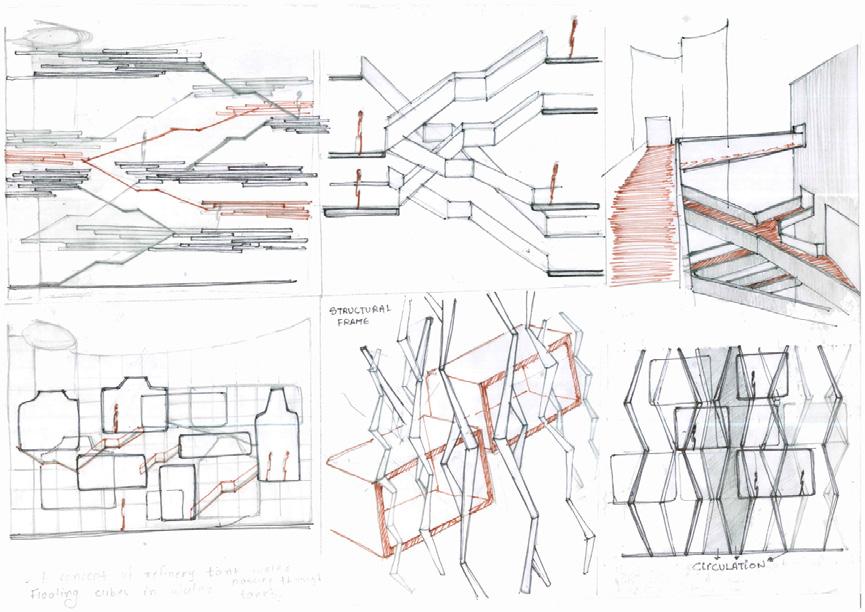
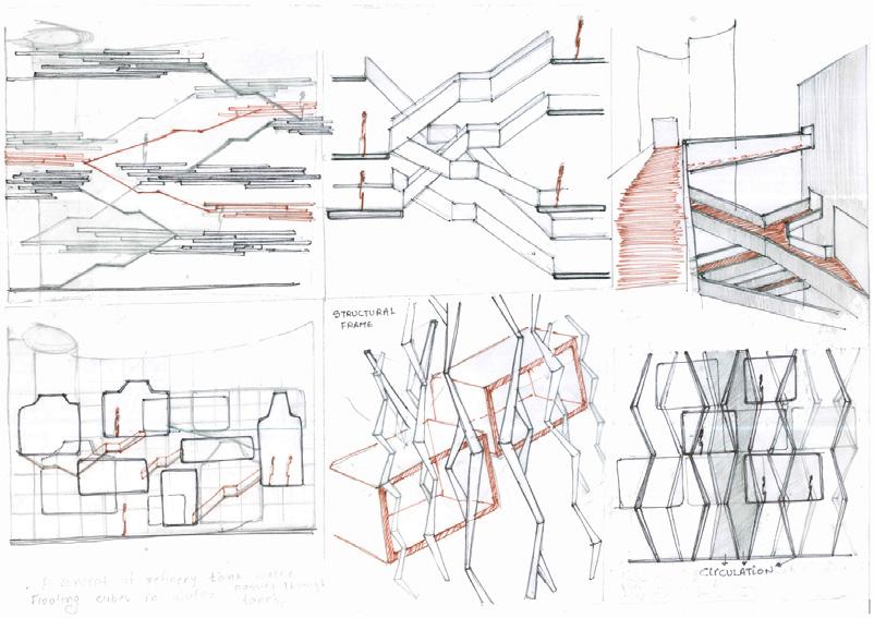
Circulation bride explorations
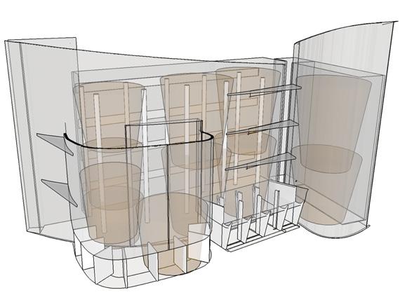
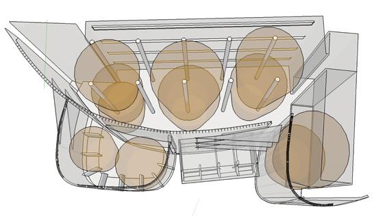
Final Project
Well of Assembly
Exercise Brief & Attempt:
Site: Prathma Blood center by Gurjit Matharoo located in Ahmedabad. Prathma Blood center was establised in year 2000. Function : Everything Related to Water. Translating the Mass Model as an Assembly System in the Site to fulfill the function for a space related to Water. Kit of Parts, Modules, Elements, Components, System derived to make a mass model is used as a process to develop a System which fits best with the particular site and function and shows how assembly based System change with change in site and function.
Learning Outcomes:
Site and function are very important criteria as a driving force to derive a system and also responsible for change in the system in Assembly Based Construction.
Site:
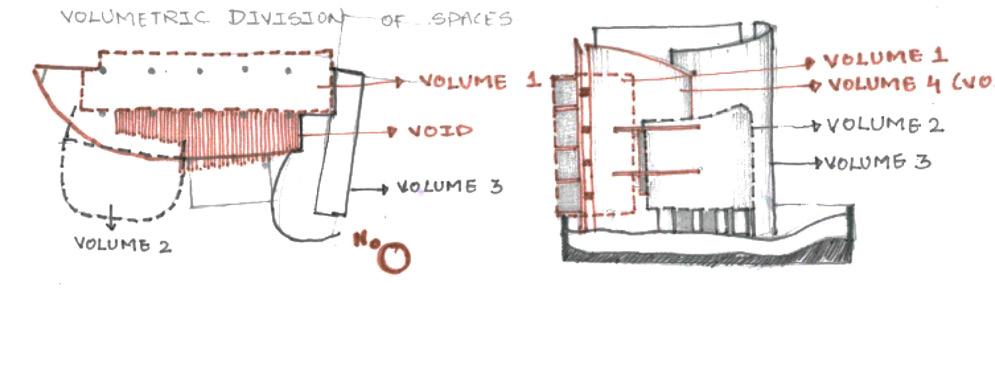
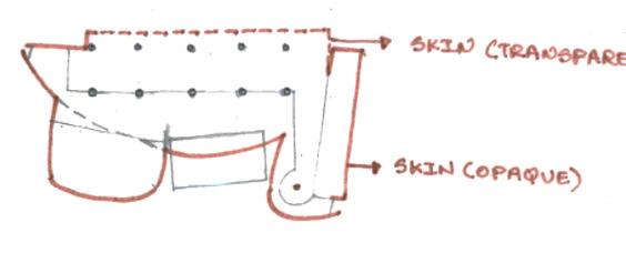
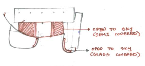
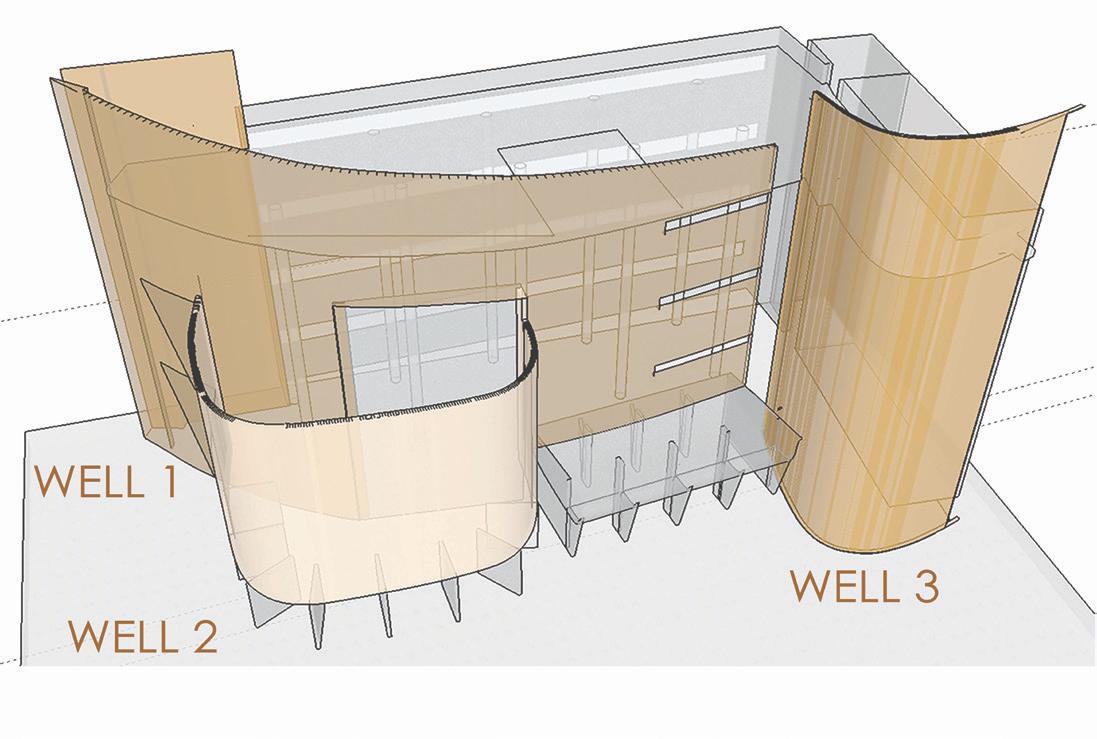
Site clearly has a void spaces formed between the original core working glass box which is wrapped as a skin of intuitive curved concrete walls. The huge 4.5 storey void between concrete curve walls and glass box create a sense of experience of a deep inside the Well from within. Three wells are experienced in the site all which intersects with each other as walls and thus interlocks as a volume at different heights. These wells (curved walls) are of different geometry so forms different scale of volumes. These strong geometry of the site influence the form and design with Kit of Parts. Hence the concept of giving different experiences of Wells in these primary three Wells is the reason guiding the process. This helps carry out different function with own privacy and ambience requirements for each activity.
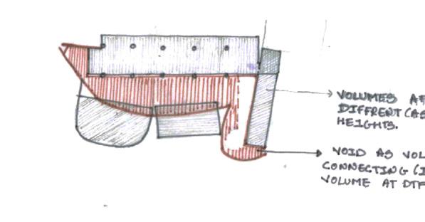
Voids as volumes connecting unterlocking volume at different levels
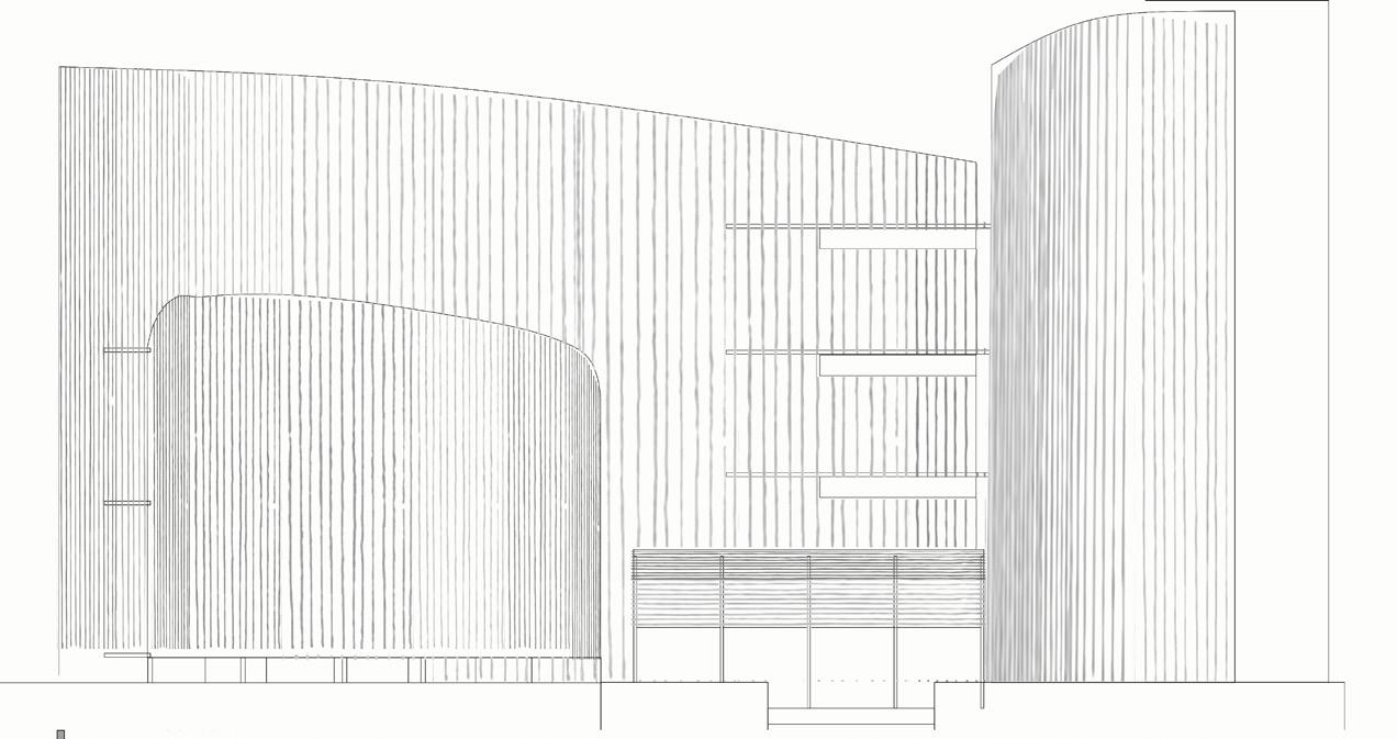
Site facade Entry
Site plan at + 250cms
Curved wall as opaque
Short section from elevation B looking towards elevation A
Section looking towards curved walls
Volumetric division of Spaces in site.
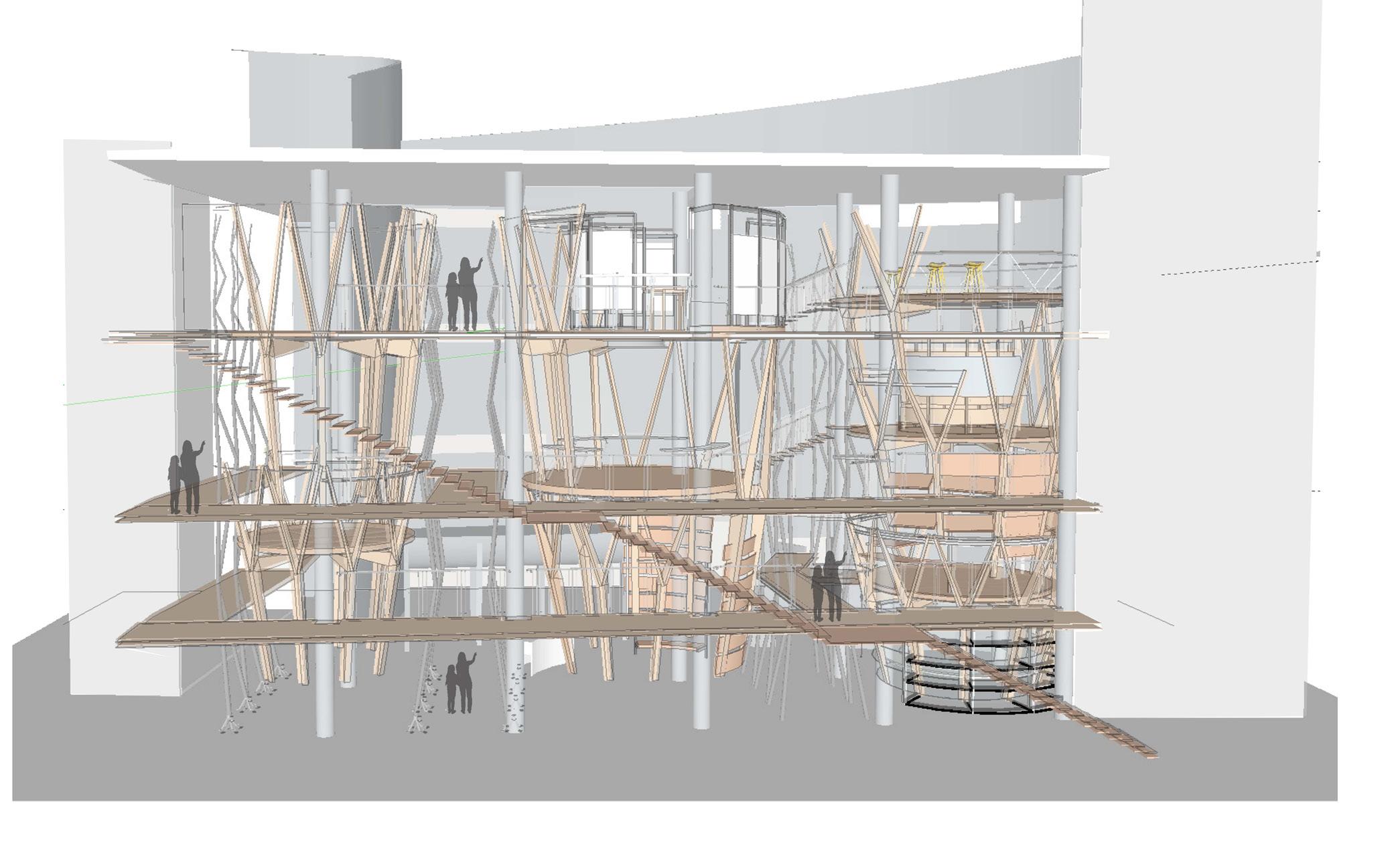
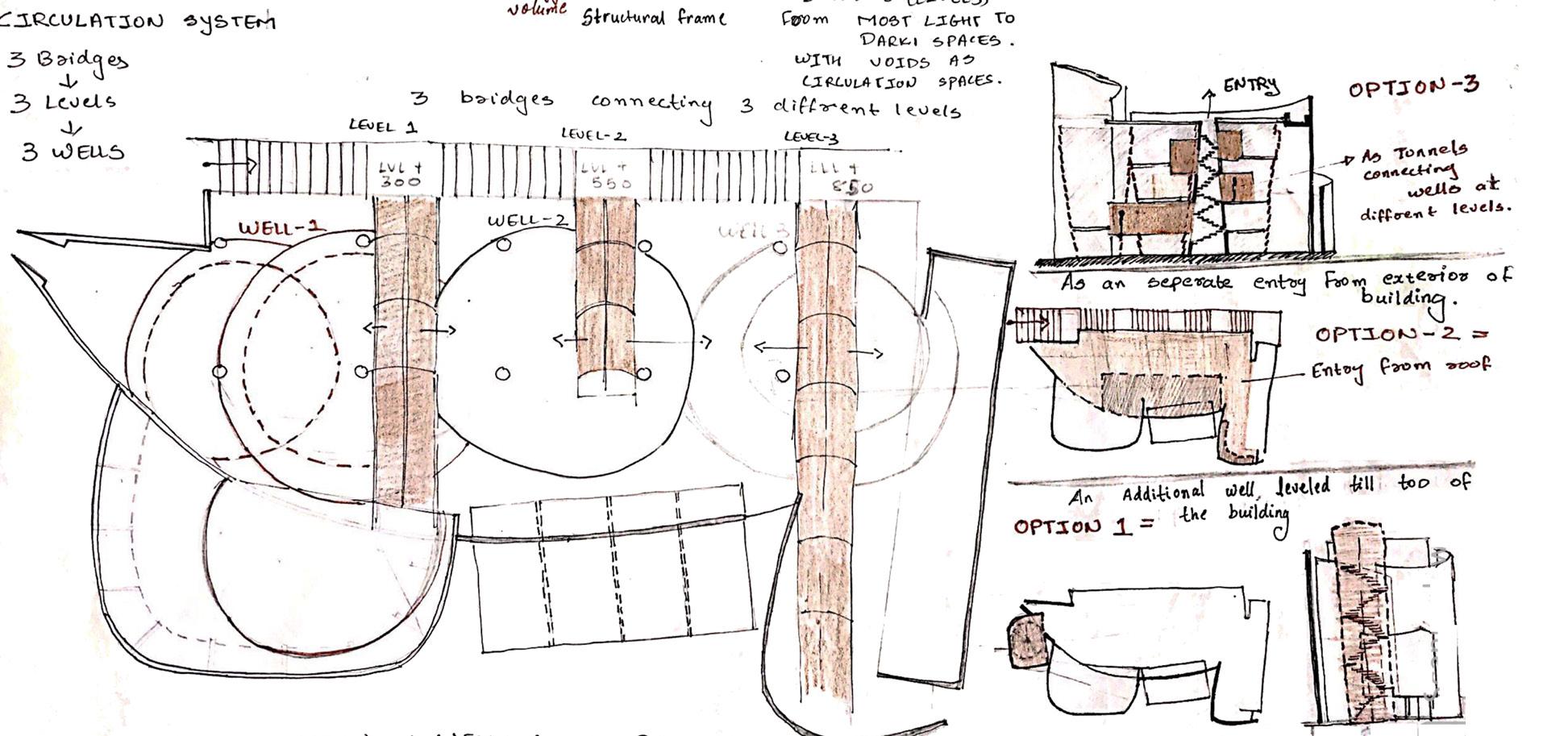
Proposed design showing Wells Arrangement in linear order with circulation bridges connecting togeather by a long staircase on nortern Facade.
Site Excitements:
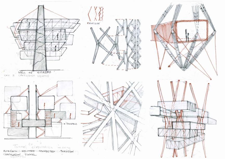
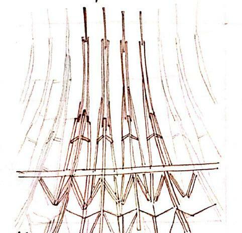
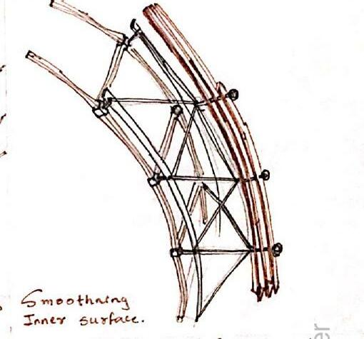
The initial design process started with Site Excitements considering the site, mass model and Structure in mind , Excitements for insertion in site are cateorized in below mentions ways.
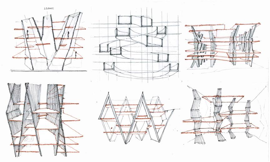
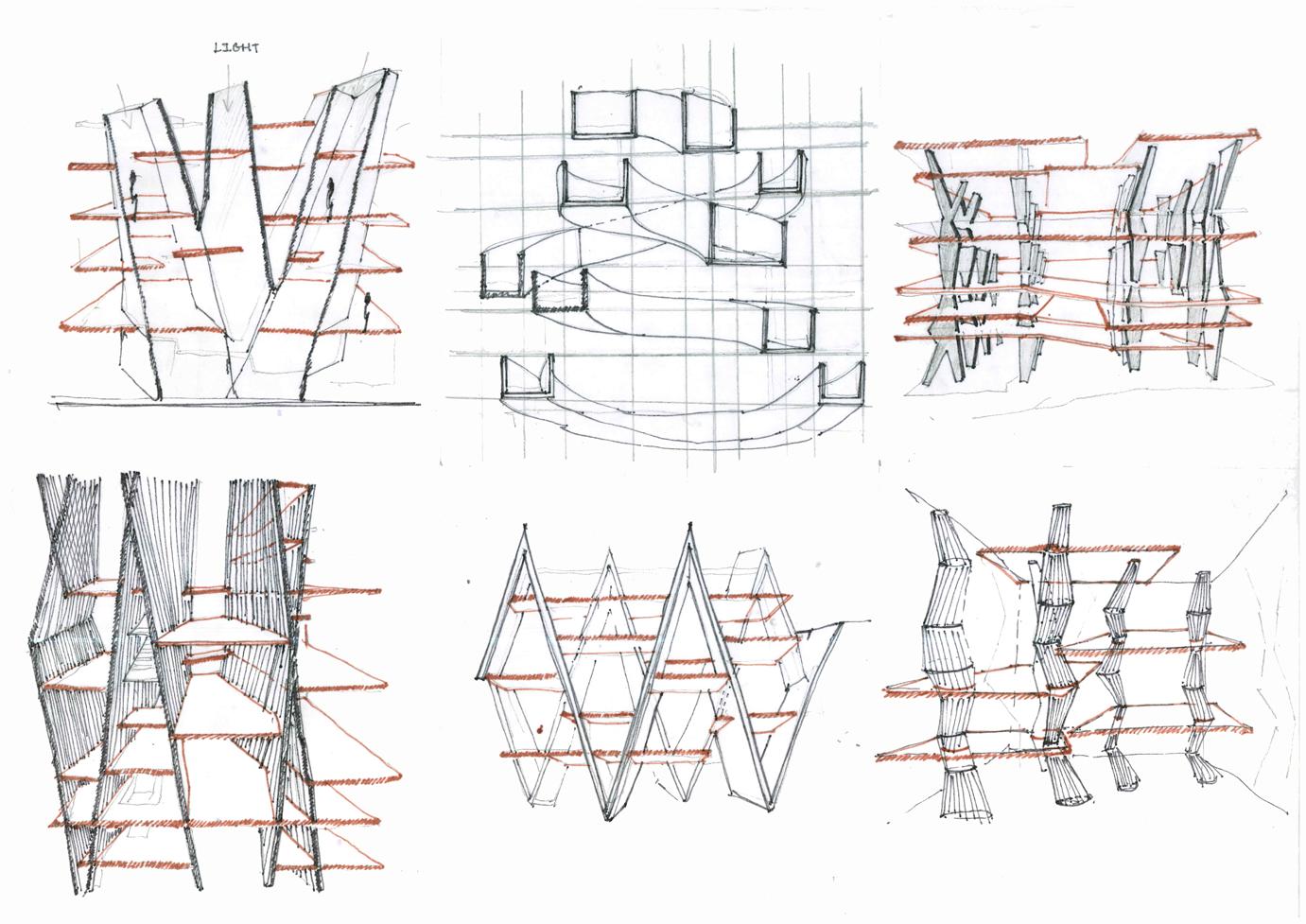
A. Sketches inspired from form of mass model.
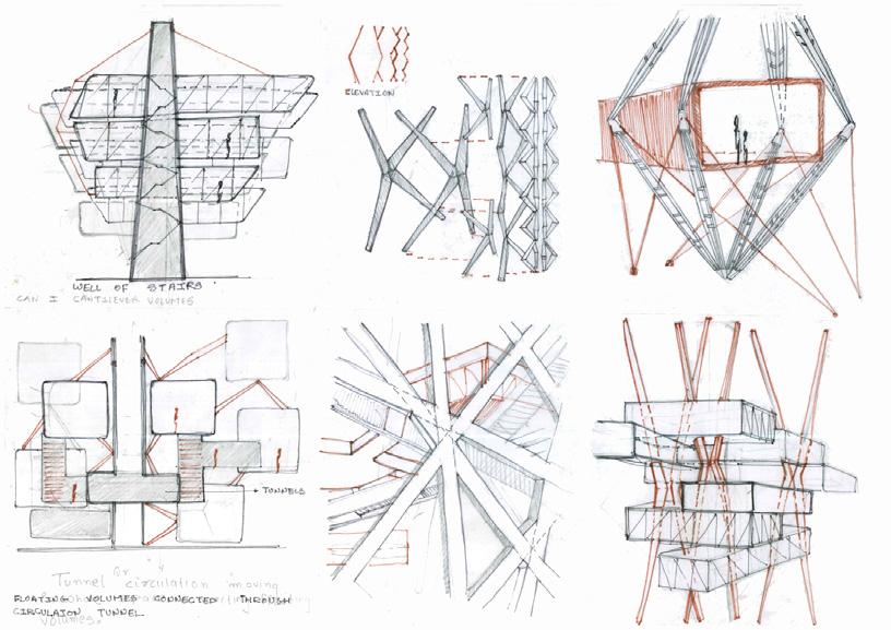
B. Sketches inspired structure with similar experience by famous designers.
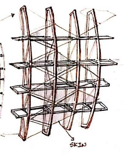
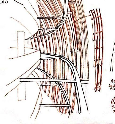
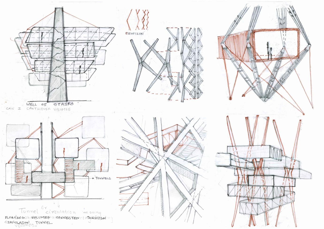
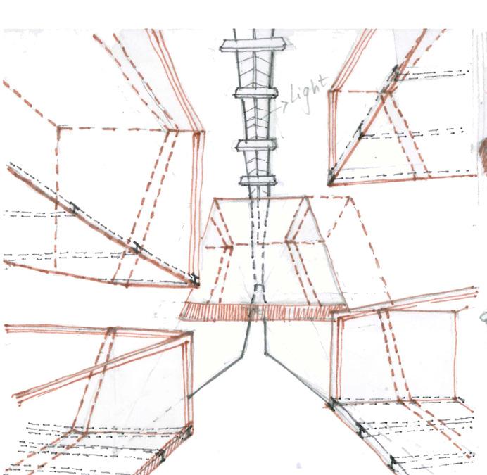
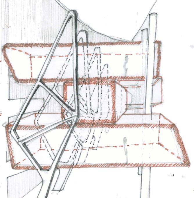


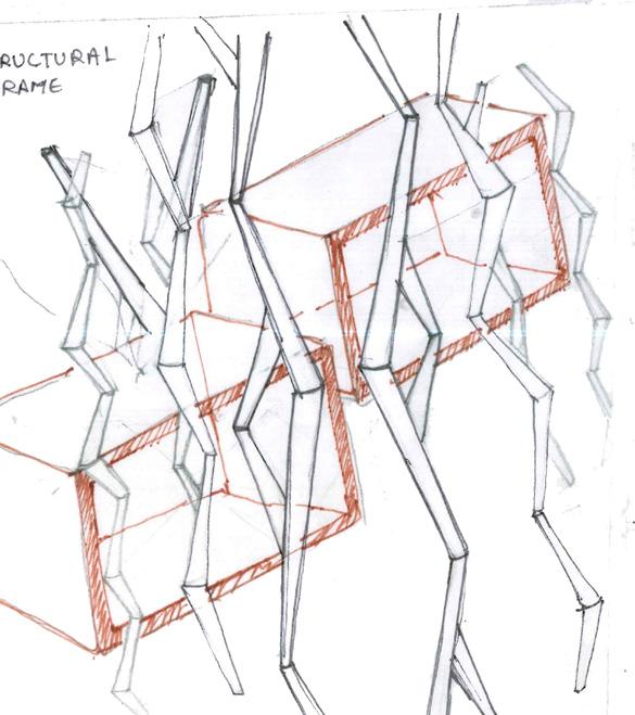
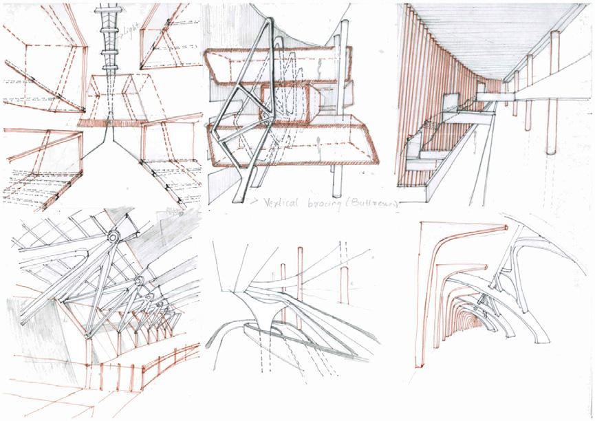
C. Sketches inspired from current experience in Site (Prathma Blood Centre).
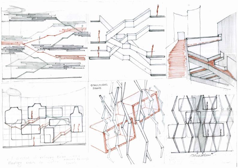
D. Sketches inspired from technology and engineering in Assembly Based Construction. This exercise helped open up the mind to look into worlds the use of Technology and Engineering used by famous designers to develop a form, with a stable system and material optimization along with designing an ambience for the space.
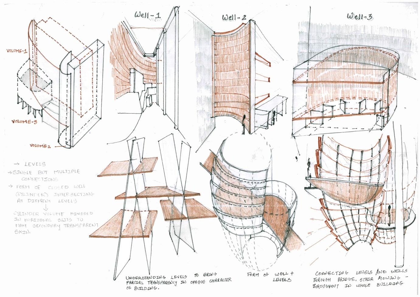
Site with huge void and play of interlocking of spaces at different height bought in the excitement to explore volumes with levels, at different heights with multiple connections and to derive a form with a Transparency to Curved Walls used as Backdrop.
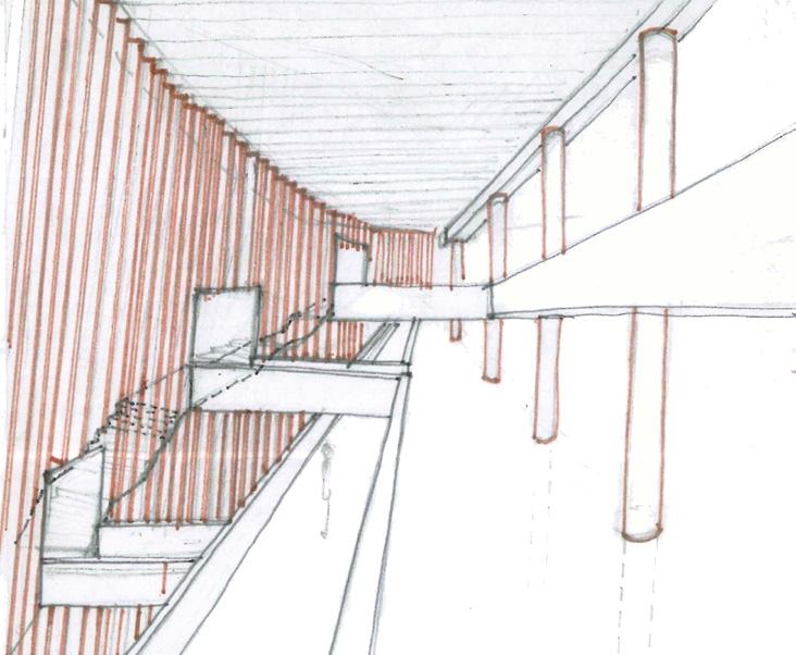
Excitements of Assembly from Mass Model:
Can a branched frame become a network to volume at different heiht?
Can mass model derive a Form to create Narrow, Longer spaces?
Can the frame of volume of masss suspend Cuboidal Volumes?
Can a common frame of support interlock with different Cuboidal volumes ?
Can it have Transparent outer skin as a structure gradually reducing in size while moving upwards?
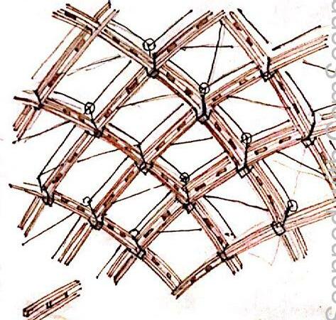
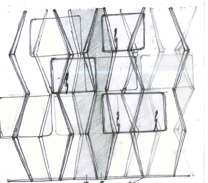
Can a single well of circulation connect volume at different levels?
Can it be tunnel of staircases connecting different levels.
Excitements of Assembly Based on Multiple Level connection: Excitements of Assembly Based on Volumes :
Can a grid of vertical members interlock at different angles to create different levels?
Can all volumes connect togeather for a common circulation system enclosed into a transparent skin?
Can it have a series of designed column to cantilever volumes at different heights?
Can a wall brace, interlock, popout, cantilever different volumes at different heights?
Excitements of Assembly Based on Technoloy and Engineering
:
Can a bridge have a Compression Member of wood to suspend Wells?
Can it be a grid of horizontal and vertical diagonals interlocking each other as a structure for well?
Can it be combination of metal and wood as a structure for Well?
Theory of Design : Orchestration of Spaces through Water



View showing the exterior facade of space (Curved walls) perceived as Well in Existing built form.
Concept of water as a function to site:
A. Water takes form in which it is poured so spatially arranging/ organizing the new insertion of Well such that it forms a secondary skin inside the primary skeleton of Well and thus harmonize element with site.
B. Water is non stoppable/Nothing can stop it from flowing and so form of well is such that it tries to escape from the opaque skin of site.
C. For understanding levels (looking for partial transparency in an opaque building as backdrop through interlocking slits supporting levels.Understanding form of water which tries to escape unless poured in vessel so the form of well connecting levels through bridges and staircases.
Huge volumes of void in well 1 , Long , high and Narrow volume in well 3 and cuboidal volume
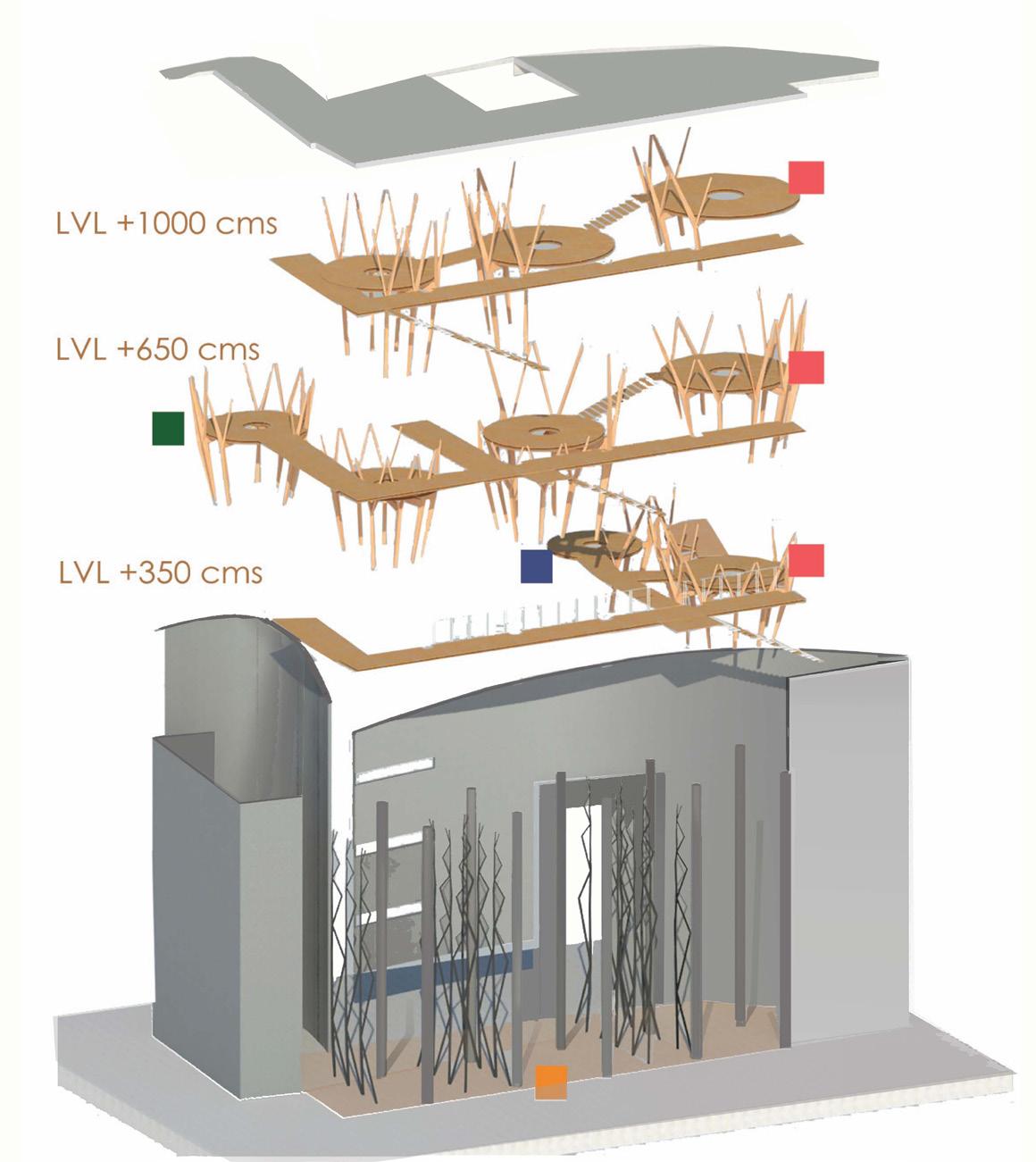
Schematic Exploded view showing layout for circulation in the space to Wells.
Intersecting of two planes supported with horizontal planes levels
Form of Wells (Split, offsetting to create different level
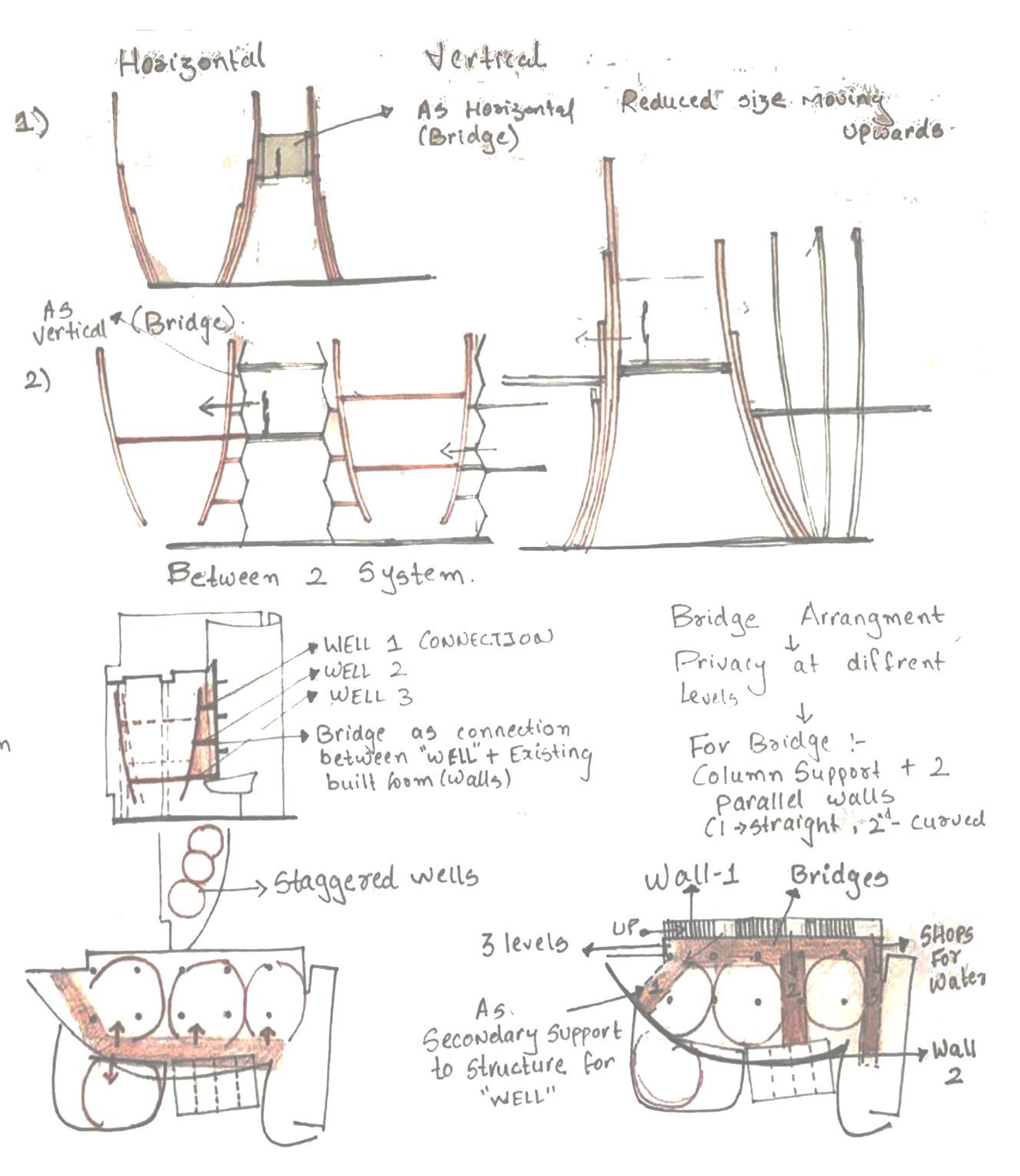
Connection through bridges and tunnels at different levels.
Design is to create small Wells in 3 primary wells of the site.
These wells are as a function added inside a semi closed different volumes because of offsets, interlocking , intersecting and so creates different experiences in each Wells. These wells are to add water as a function in Social well(water fo social causes), spatial well (experience of water), spiritual well (use of water in religious activities, scientific well (Research on water), Shop of water products etc.
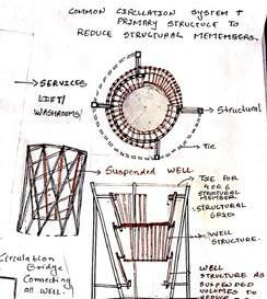
Service (Lift, Washroom)
Spiritual Well
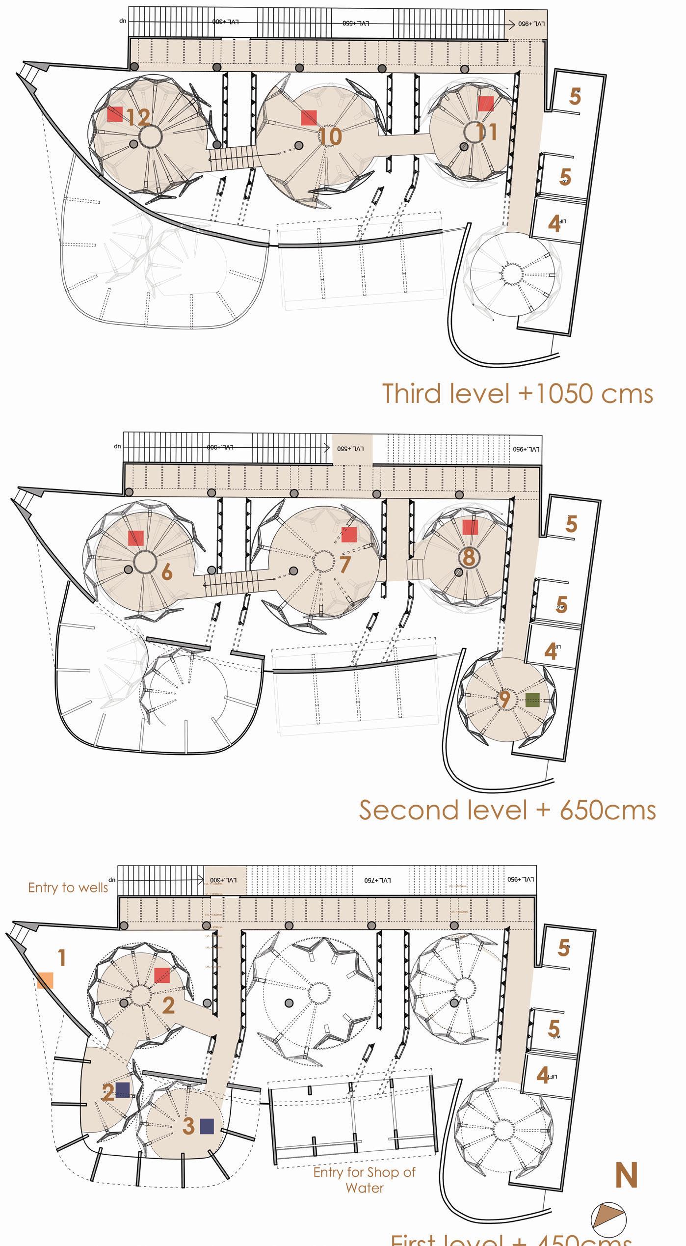
Activity Layout Legend
1. Voids in Well for Shop of Water.
2. Social well (hydrotherapy center)
3. Research Well
4. Lift
5. Washroom
6. Aquatic Life Exhibition
7. Aricultural activity
8. Activity related to research of water in Medicine.
9.Spiritual Well Sound Therapy related to Water.
10. Exhibition zone for water in future life.
11.Activity for Relaxation of mind.
12. Cafe .
Research Well Social Well
Bridge connecting Exhibition area with Cafe.
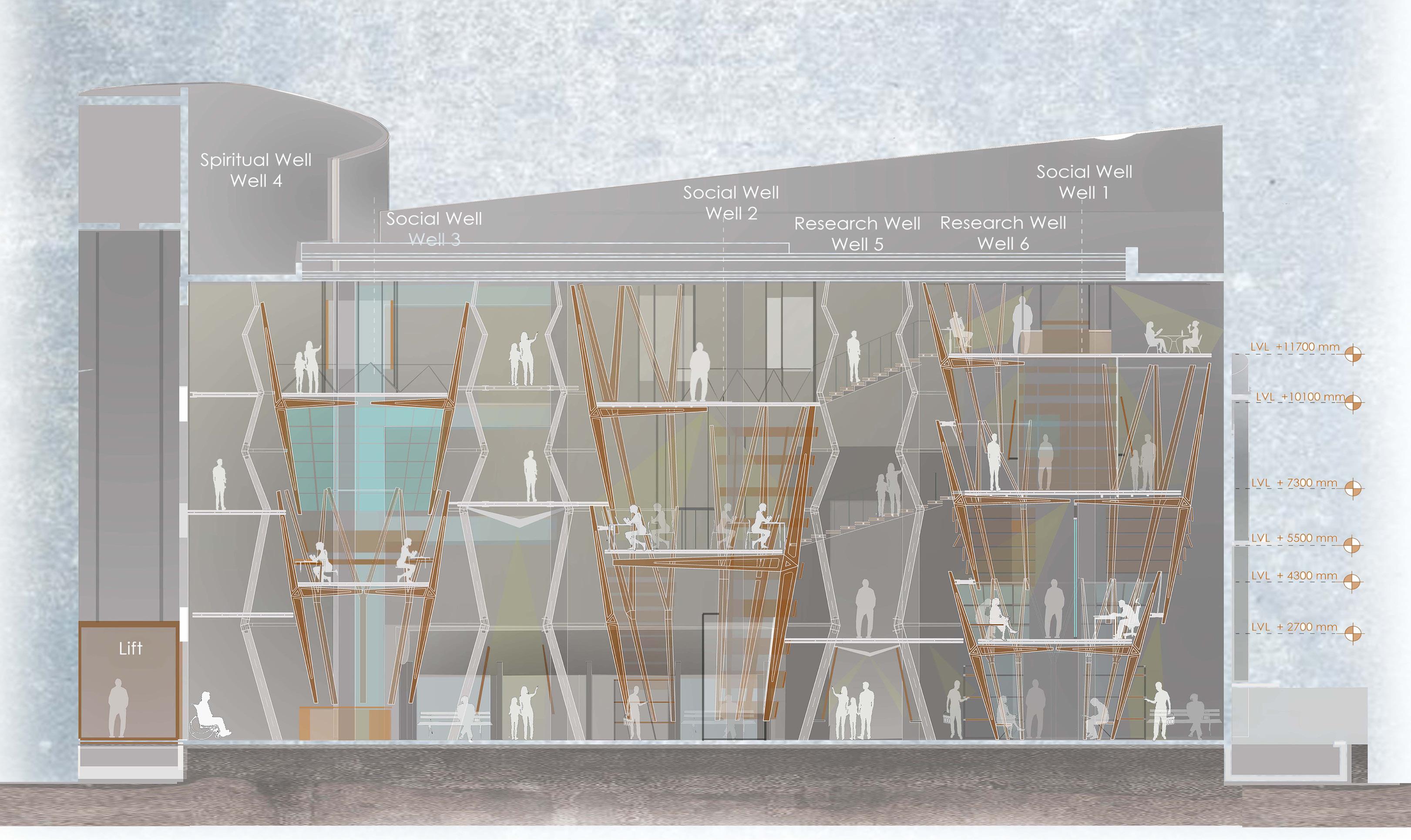
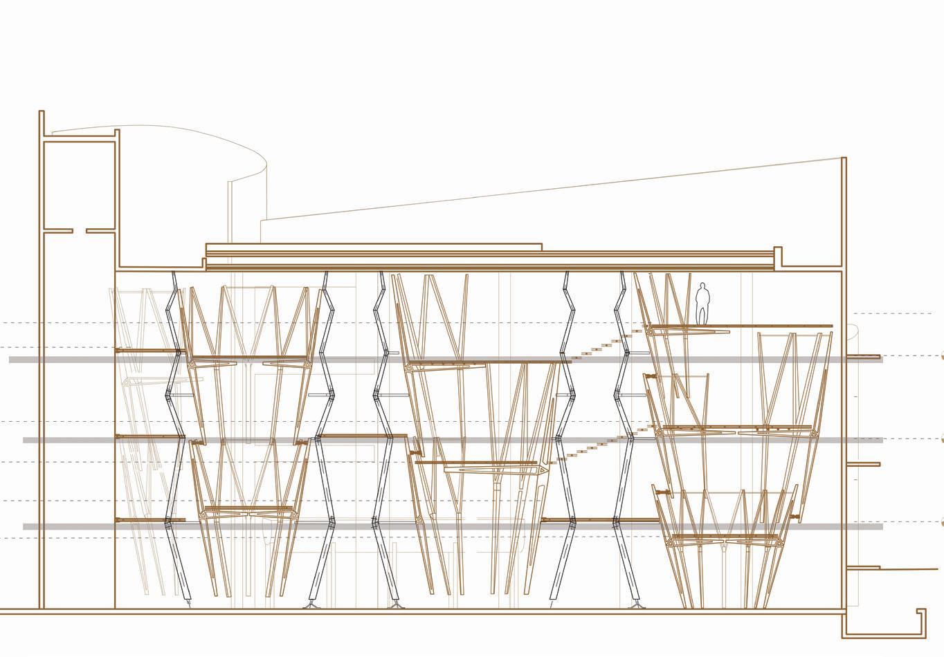
Long Section showing the forms of Wells with Bridge Arrangement for Proposed Levels in Relation with existing levels of Site.
Proposed Floor Levels
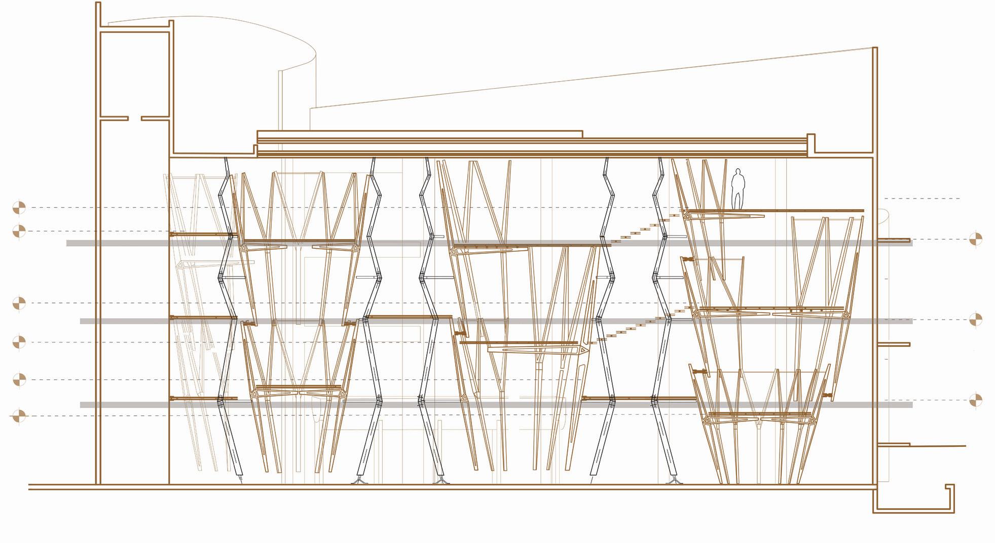
Existing Floor Levels
Social Well for Water
Water in Agriculture Exibition and small activity.
Hydrotherapy as Activity. Water in Medicines.
Importance of Water in Aquatic life Exibition
Activity for Relaxing mind through water.
Voids as shop for Water Juice from Fruits and vegetables. Water from oly Rivers , Lakes etc. Water with addin special chemical compounds to boost immunity etc
Bridge connecting Social Well with Spiritual Well.
Staircase connecting all bridges connecting each Well on North facade of builtform.
First Level at +450 cms
Bridge connecting Social Well with Research well.
Research Well for Water Small labaratory with research on water . Produce new products for Shop of Water.
Spiritual/Reliious Well for Water
Sound Therapy related to water to concentrate and focus mind in Spiritual way .
Form and Structure Derivation of Bridge with respect to Site and Well
Module Scales as A multipurpose modules i.e A surface of one well and Base support for other.
+ +
compression Member as rid of structure which assembles all Subwells of Primary Wells togeather.
Reducing the module number i.e decreases in density of Skeleton Structure to achieve a stable structure.
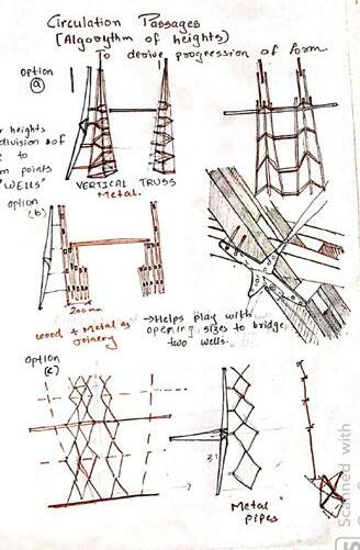
Circulation Passages(Algorithm of heights to derive Progression of forms.)
Bridge (Form) Elevation Detail
Vertical Truss (Metal)
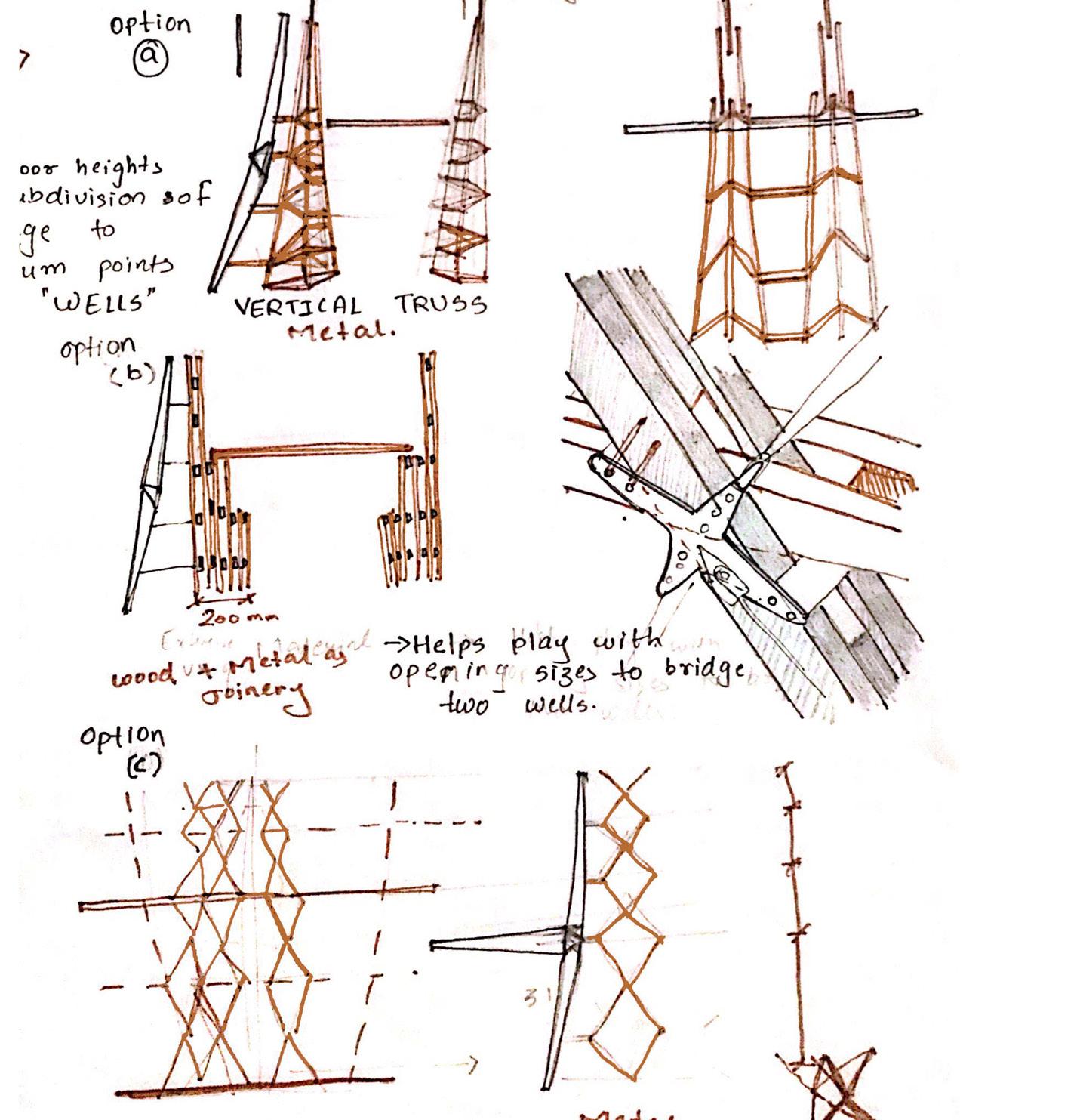
Wood+ Metal helps play with opening sizes to bridge two well.s
Metal Truss (Pipe) Derived from Mass model+ Shop for Mask.
A. B C horizontal (Well ) + Vertical System (Bridge/Circulation)
Form and Structure Derivation of Skeleton
of Well
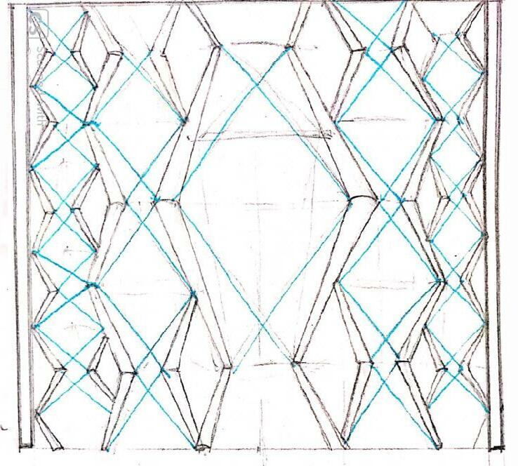
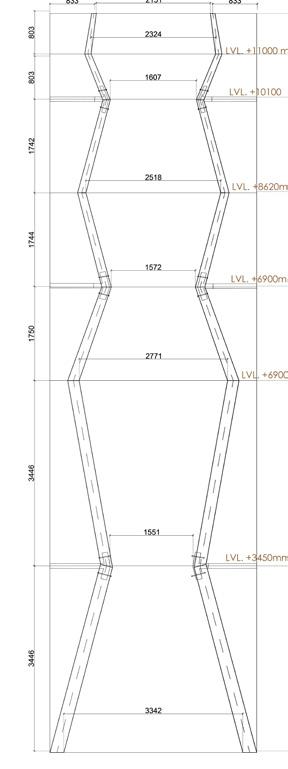
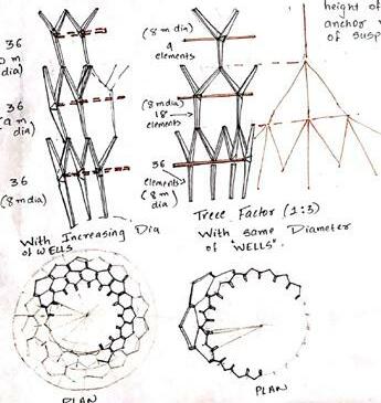
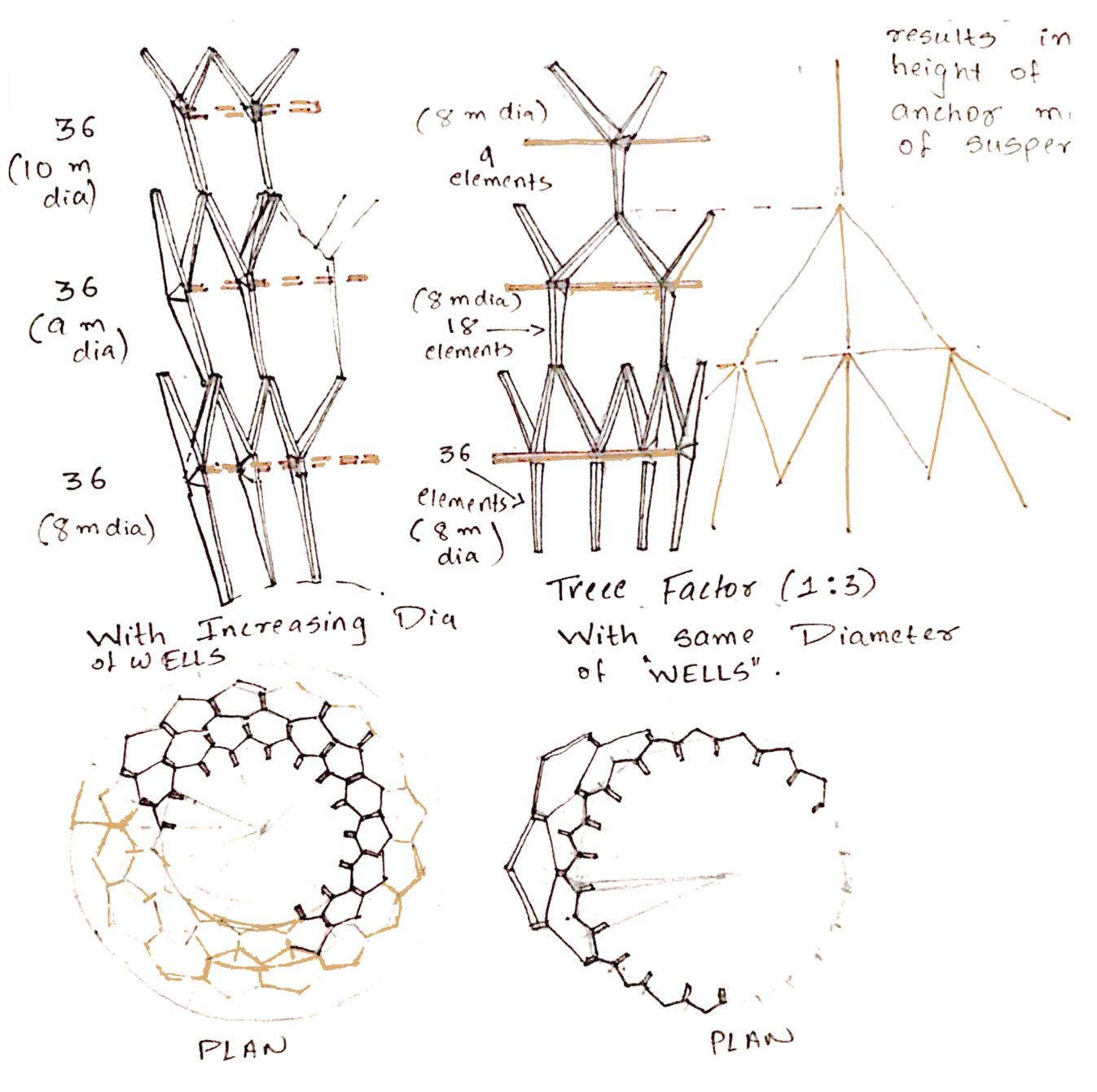
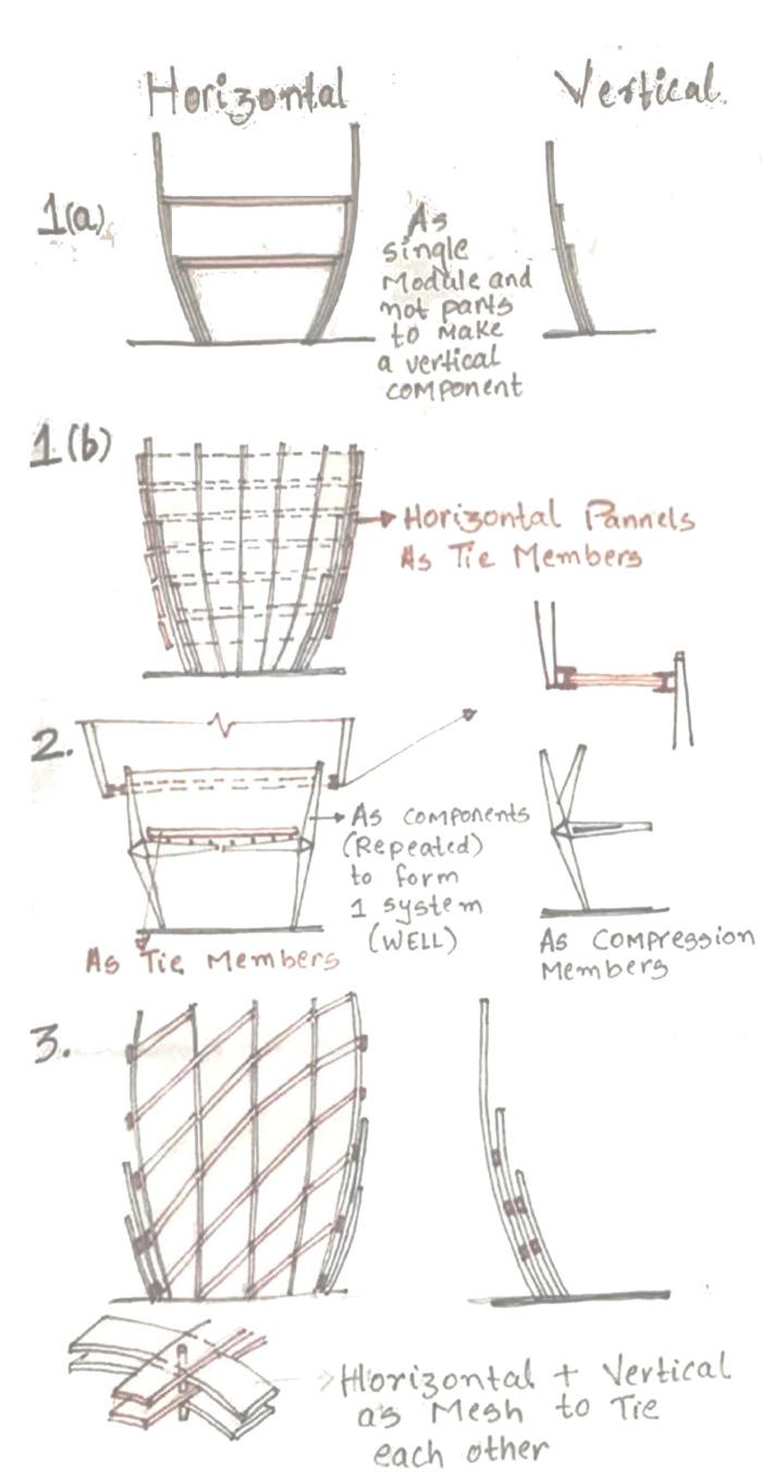
To harmonize site with the insertion (Wells) a seperete algoritym is worked out were their is proressive arrangement of different levels in well which are derived form the height of the levels found in existing site. Progressive geometry of decrease in arrangement of members in well surface while moving upwards.i.e 36 module forming well ----- 18 members and upto 9 members forming well surface. This progressive geometry is also derived considering the structure of the well were lower volumes accept the maximum weight compared to the most upper volume so gradually decresing of size and number moving upwards. 4 experience with same skeleton but different skin a. One common (12m ) vertical compression member gradually decreasing with horizontal levels as their supports. b. One common (12m ) vertical compression member radually decreasing with louvers as horizontal members joining two vertical.
c. Different vertical members for each well and well as form offested and are assembled to develop on common well.
d. Mesh of horizontal and vertical members in Form of a Well as standalone Structure.
Well with Increasing Dia Well with same Dia but propaative module in ratio of (1:2:3)
Horizontal and Vertical grid options to develop Form of Well
Slice the Form, Offsetting the Form, Scaling the Form
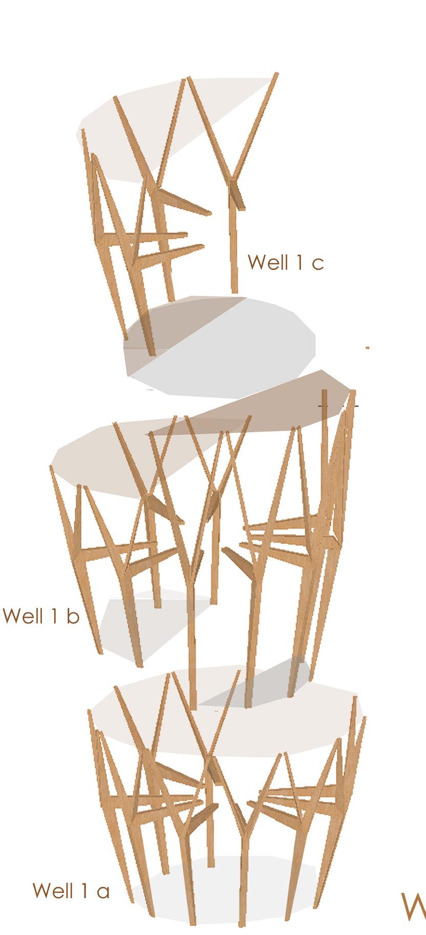
Well 1 c 4 modules
Skeleton of Suspended Wells
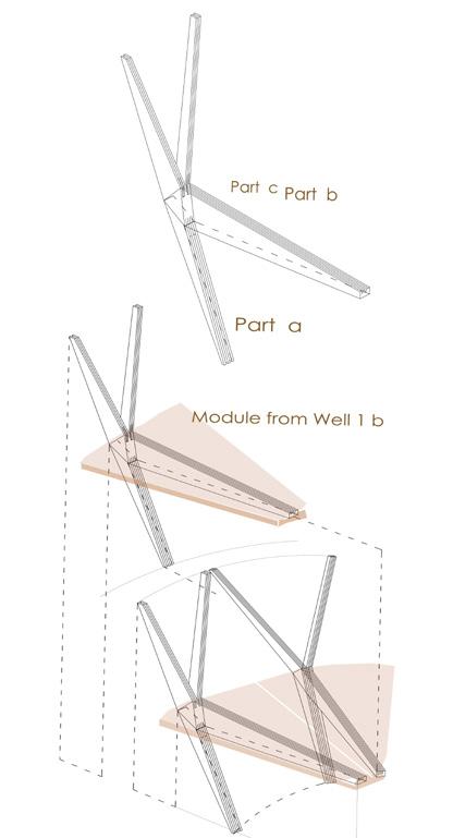
Part A Part B
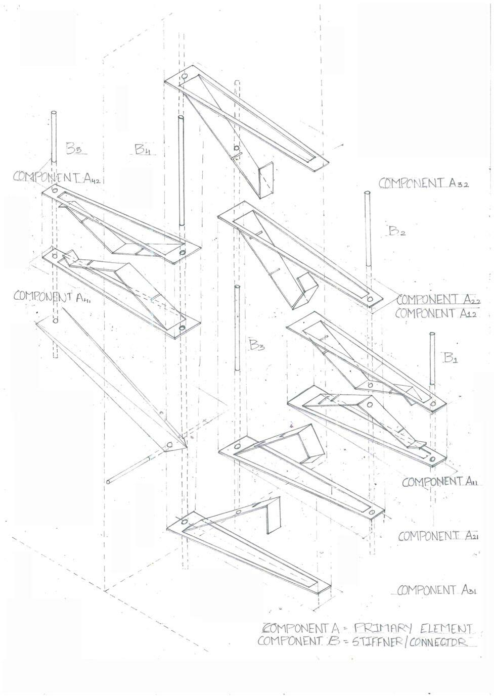
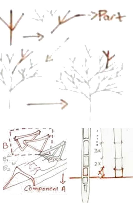
Module 1 divide in 4 Kit of parts. a. Lower stem part A. b. Cantilever Part as a Beam for Resting Floor on it. c. 2 branched Flange from Part A( as a member for further contuining the chain for Well 2).
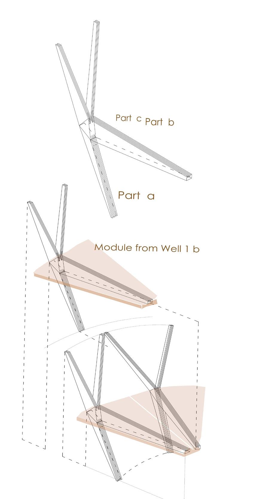
Part C
Well 1 b 8 modules (2 from each )
Bigger Modules
Well 1 a 12 modules
Module of Well 1b
Module of Well 1a
Thickness of Part a is double the thicknes of part c. 2 x Thickness of part c = Thickness of Part a Further For material optimization and reduce the visual heavyness of the element roves are created such that all 3 parts of module slides and fits in one other (as in Detail A on p 25)
Well in Site Site From Well
Well form responding to geometry of site (i.e curved walls so circular form with skeleton as semi transparent surface wit solid opaque walls curved walls as backdrop. Wells responding site through geometry and form to recreate verticality in space.
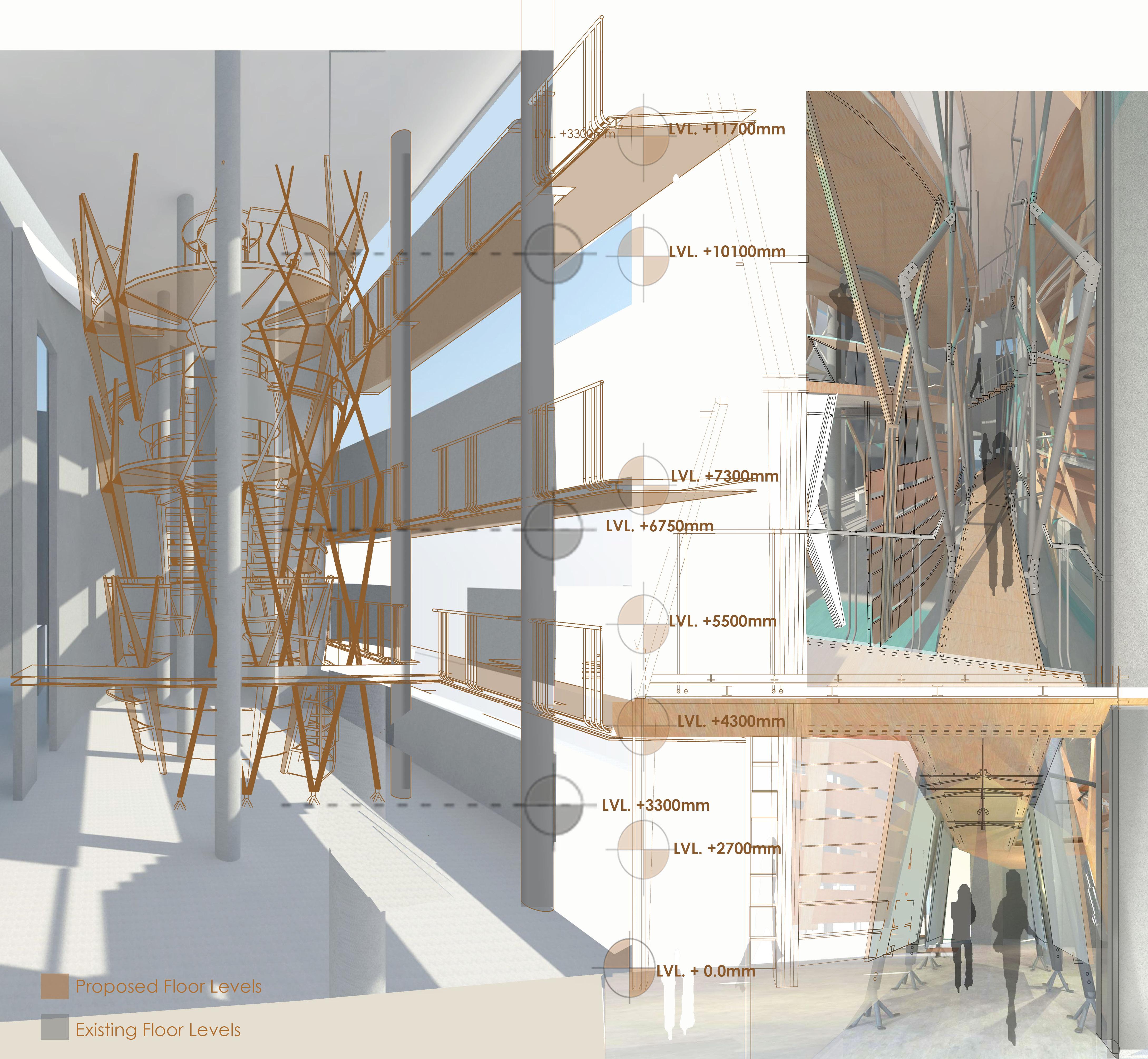
Wells recreating vertical narrow void spaces with developed kit of parts .
It responds site with creating levels to develop spatial interconnection borrowing from the heights and levels from original site.
Exploded View of an Order Of Assembly of Wells with bridge and Interior Elements
Primary structure Suspended volume Skin and interior elements
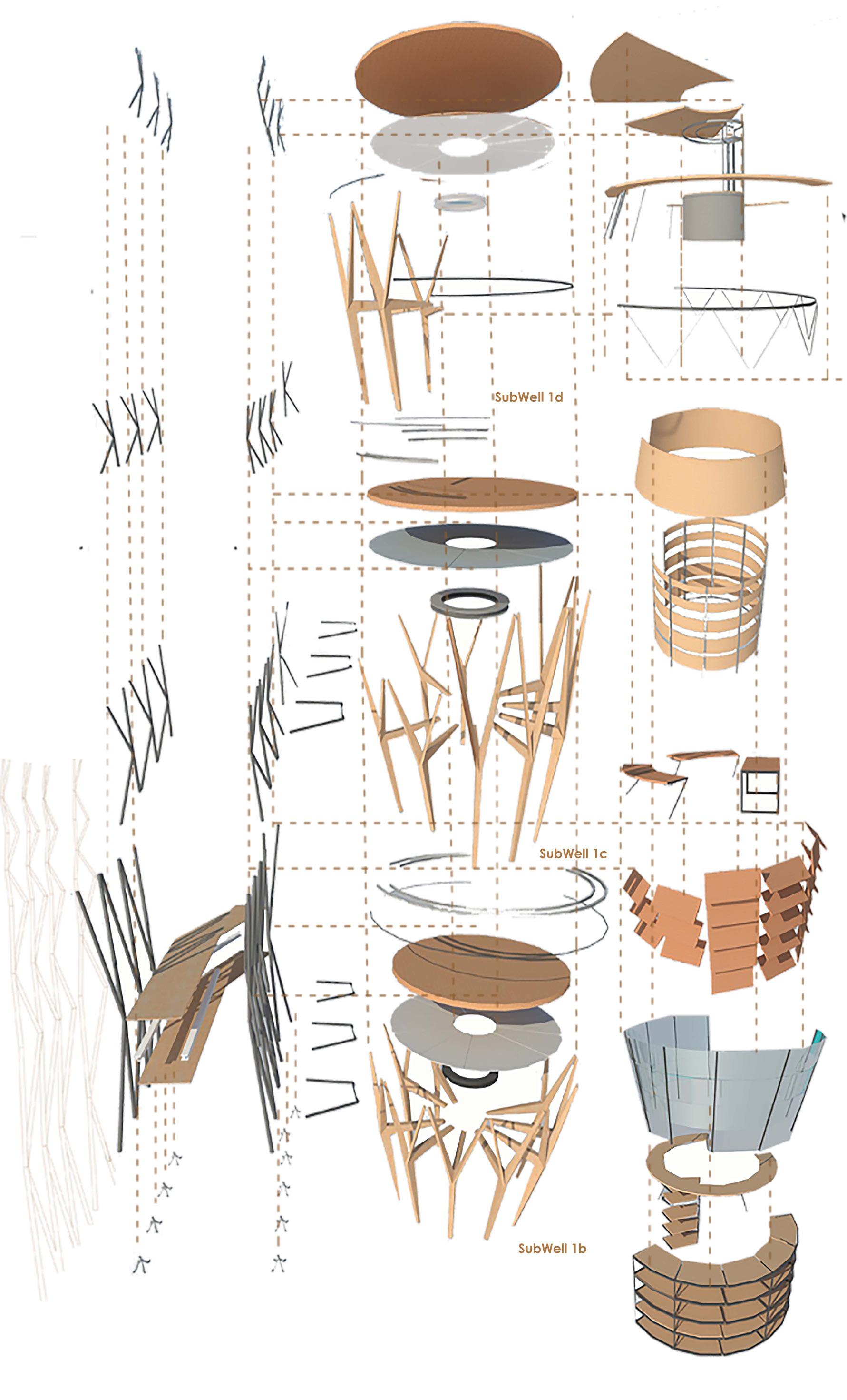
sandwich slab 200 mm thick 25 mm thick plywood on sandwiched with`` T` section of 100 mm flange.
a. 25mm thick plywood
b. 30mm thick wooden stiffners
c. T section with height 100m and 100mm flange.
d. Plywood 25 mm thick divided in 12 equal parts to assemble with the cantilever Member from skeleton of WELL module.
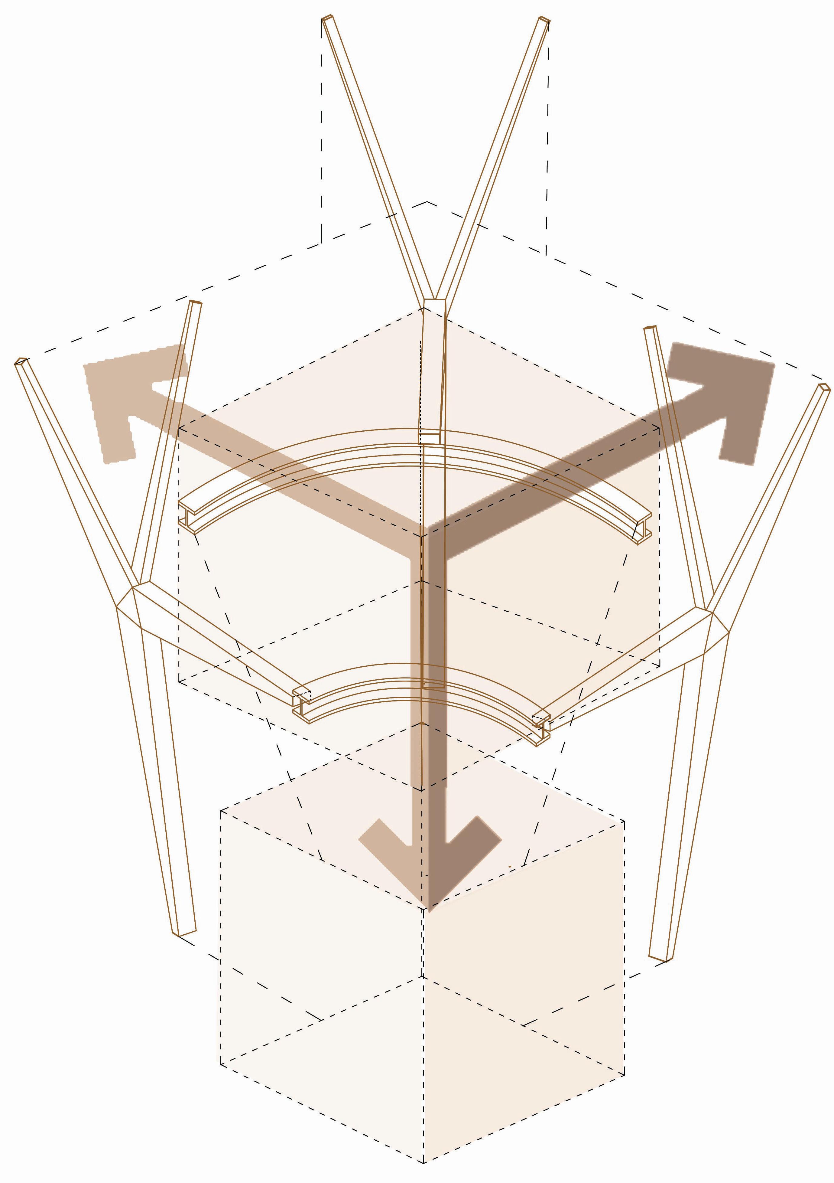
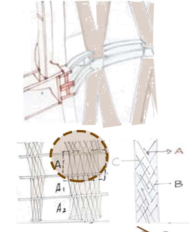
Cantilever Member of Skeleton of Well tied togeather with an I section Ring of 150cms Diameter.
Branched modules of skeleton of Well tied togeather with a 60mm dia rod in Tension.
Assembling the modules of two different Subwells with a ring of I section running around lower perpery of upper Well and upper Periphery of lower well Offsetted from each other to allow light to pass through from top to Bottom.
Scaling the half part of Subwell 1c such that bigger modules becomes a surface for Subwell 1c and floor Supports for Subwell 1d.
Cafeteria open space as Functional requirement resulted in 4 modules of skeleton . To support structure central kitchen counter with structure to support the upper modules of skeleton of sub well 1d.
high stool sitting tabletop around the periphery to again supported open Structure of Sub well 1d.
Railing as a structural member tying floor with lower module of Skeleton of Subwell1 d.
Exhibition Panel for display of Exhibition on Future /Aquatic Life under Water.
Structure for Display of exhibition is an offset of Form of Well which partially transfers the load from Floor of Well 1d towards well 1c and further down.
Semi open space as a functional Requirement to allow controlled light and vision in the space. So Space in a Space.
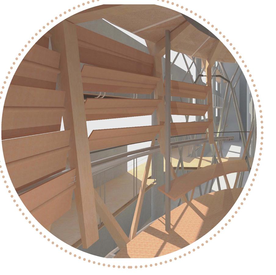
Waiting Area for appointment for hydrotherapy Center. Space with controlled light and vision. Privacy as a key factor to this space. So skin as louvers which ties each module of sub well 1b and also allows controlled light entering the space.
Sitting is such that it again ties the Sub module of Sub well 1b. (Smaller modules of Sliced Form).
Display rack for shop of Water is such that it surrounds well modules and act a a bracin and tied member for modules of Well ,which helps to transfer the load to round.
Exploded view of Assemly of Elements and components in WELL 1.
Vertical Assembly Between components of each System i.e Wells, Bridge and skin.(Inter System)
Horizontal Assembly Between each System i.e between Bridge, Well and Skin of Well. (Intra System)
Form of well is Sliced, Offsetted , and Scaled
Number of modules reduces and diameter increases moving upwards such that the curved surface of Site becomes a backdrop Skin for SubWells.
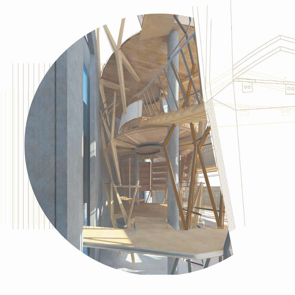
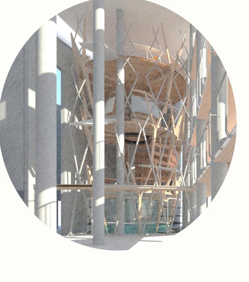
The density of members reduces moving upwards and functions are distributed such that least private
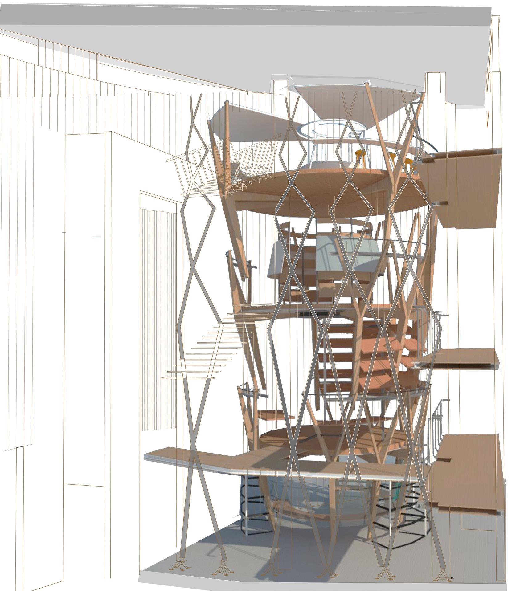
Skeleton of Well 1 + Skin for each Well such that it becomes the Secondary
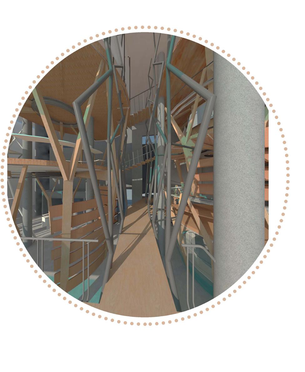
Primary Frame of Compression Members Spanning vertically to support bridges for circulation and Suspend Two Primary wells on both side of passage.
Bridge connecting Well1 of Social Well and Well 5 of Research Well.
View from Bridge 1 connecting social well with research well with compression members of bridge anchored with well modules to suspend well.
View from Entry for Shop of Water looking towards Bridge 1 connecting well 1 with Research Well
View from Bridge 1 connecting social well with research well with compression members of bridge anchored with well modules to suspend well.
Cafeteria that serves every product related to Water. Open space which allows people to wander around the spaces /activities and exhibition in other Well.
Exhibition for Aquatic Life under Water to make a life possible in future.
The structure of exihbition is such that it also act as a element to help rest the floor of Well 1d along with display element for pannel for exhibiton.
Well 1b offsetted from Well 1a to allow light from top.
To maintain the privacy of the space in Well 1b by adding a skin of louvers to the skeleton of Well 1b. Also elps help to get the controlled light from northern facade of built form.
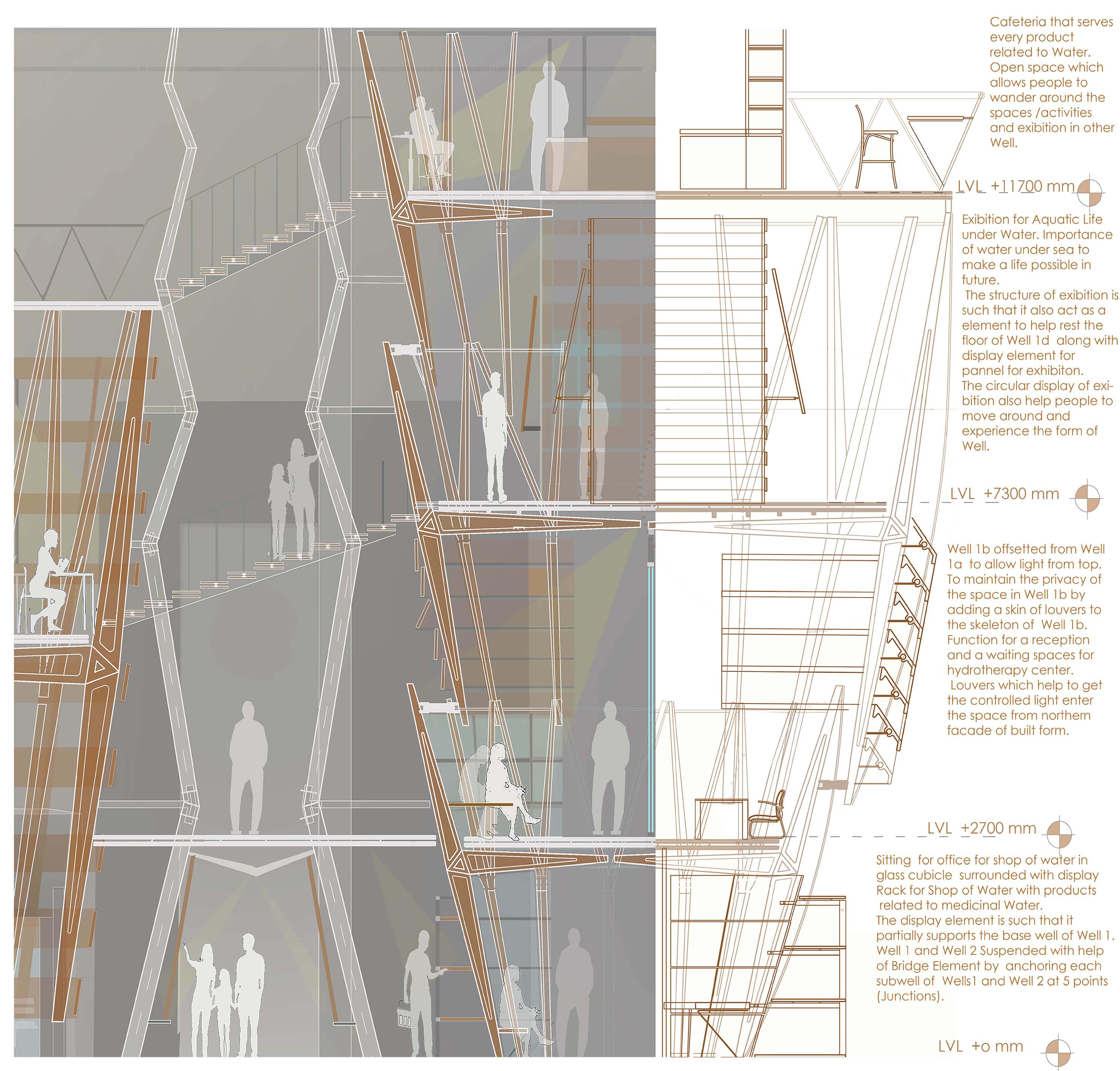
Function for a reception and a waiting spaces for hydrotherapy center.
Office for shop of water in glass cubicle surrounded with display Rack for Shop of Water .The display element is such that it partially supports Well 1.
Well 1 and Well 2 Suspended with help of Bridge Element by anchoring each subwell of Wells1 and Well 2 at 5 points (Junctions).
Social well
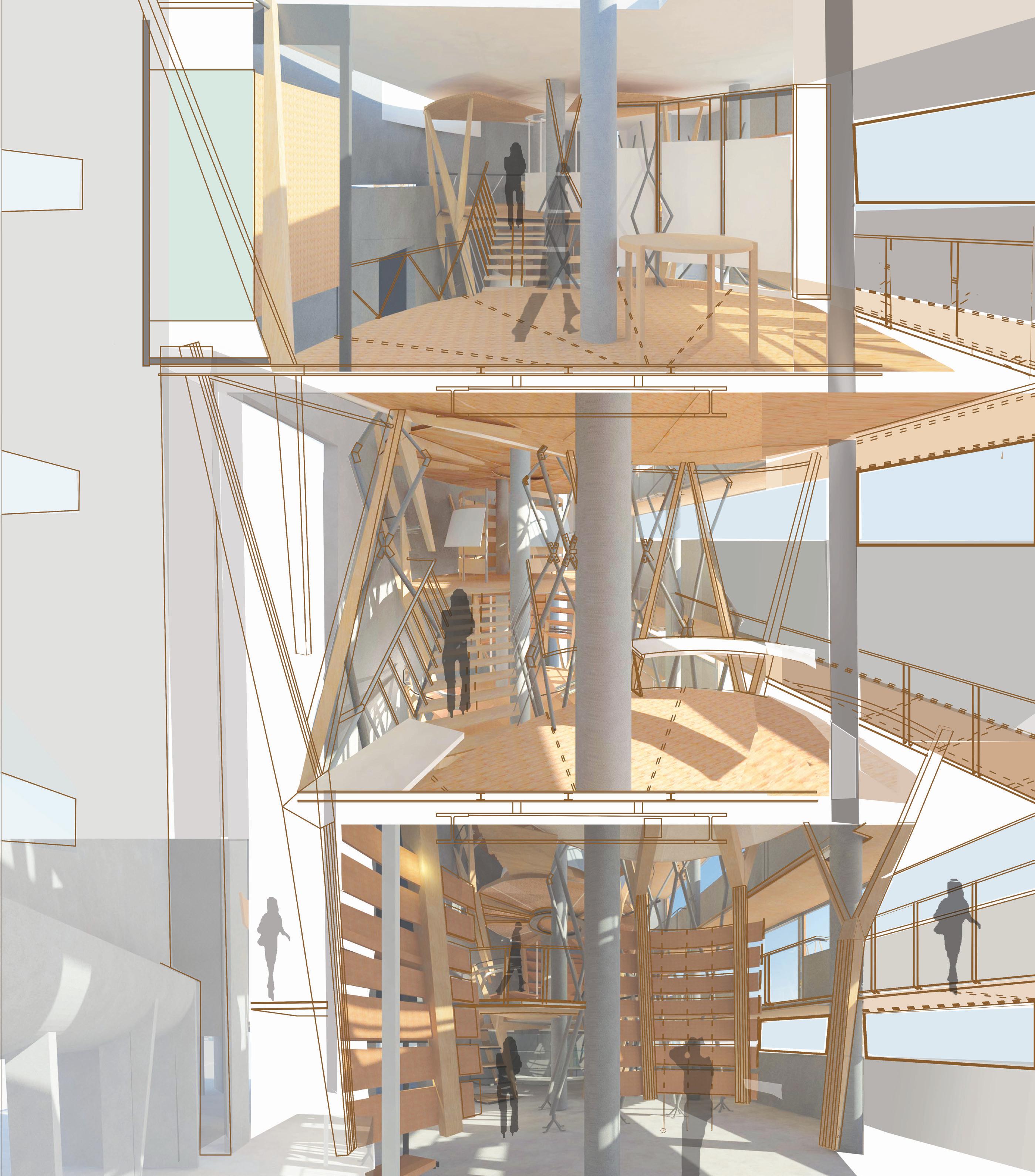
Well 1 showing the quality/Ambience of interior space along with interior elements such as louvers. railings, glass Cubicle, Sitting elements, Shop display element, Exibition Dispaly etc
View looking at Cash counter from Well2 towards Well1 Exhibition zone in the lowest well of Well2 right at entrance From Shop for Water.
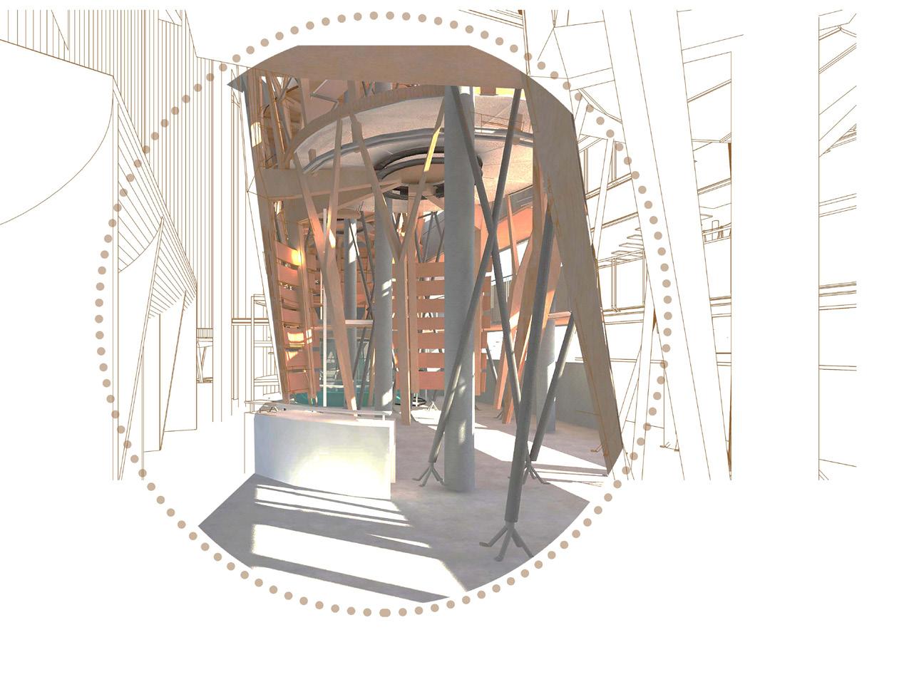
View from Staircase of Cafeteria looking at Exhibition space of Well 2 with Direct light From Roof OTS covered with solar radiant glass.
View from Subwell 2b looking towards exibition area for water
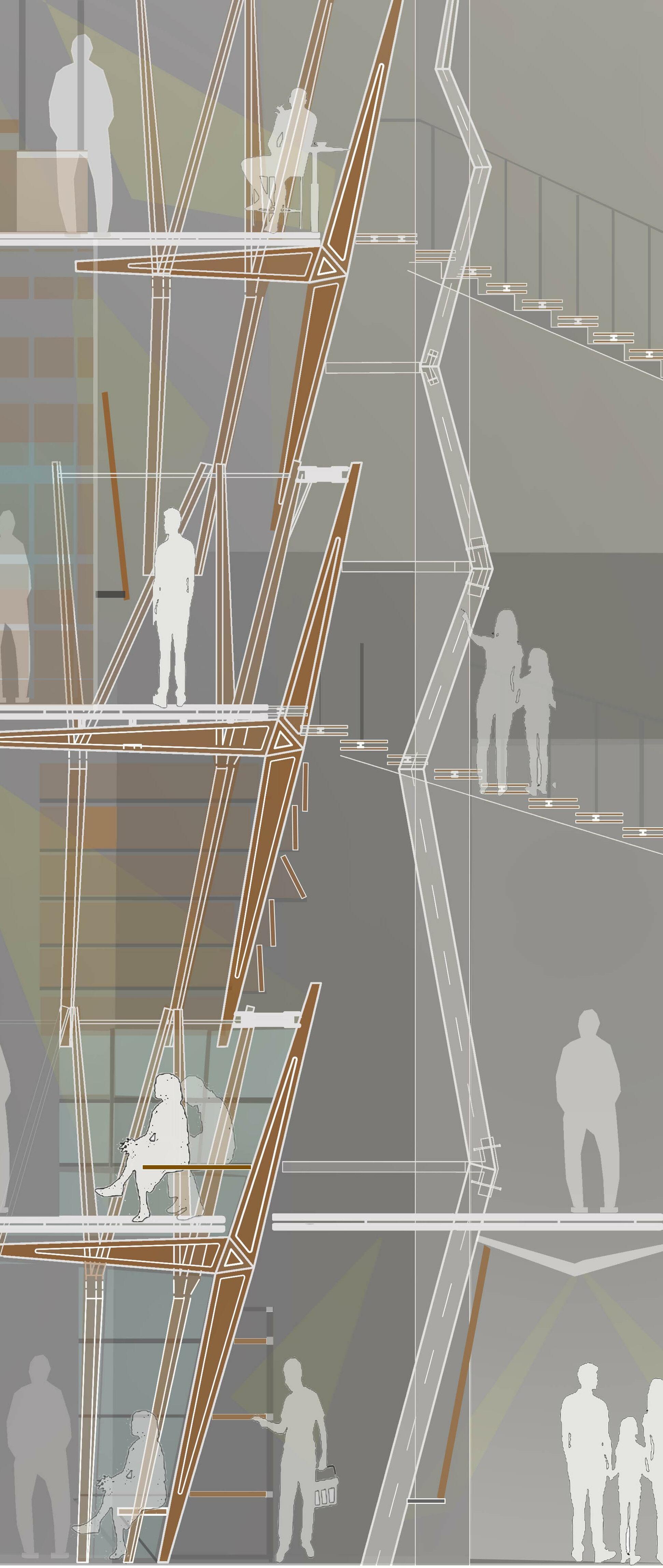
Long Section showing Activity in Social Wells i.e Well 1 ,2 and 3 and Shop for Water. Activities such as hydrotherapy center, Exhibition for future life under Water, Activities related to need of water in Agriculture, Cafeteria Etc
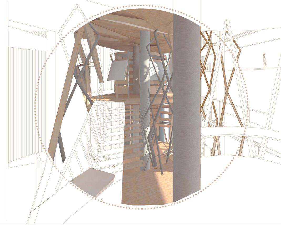
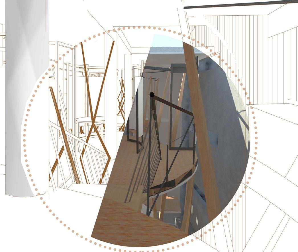
Function (Exibiton Circulation) on Bridge between two Wells
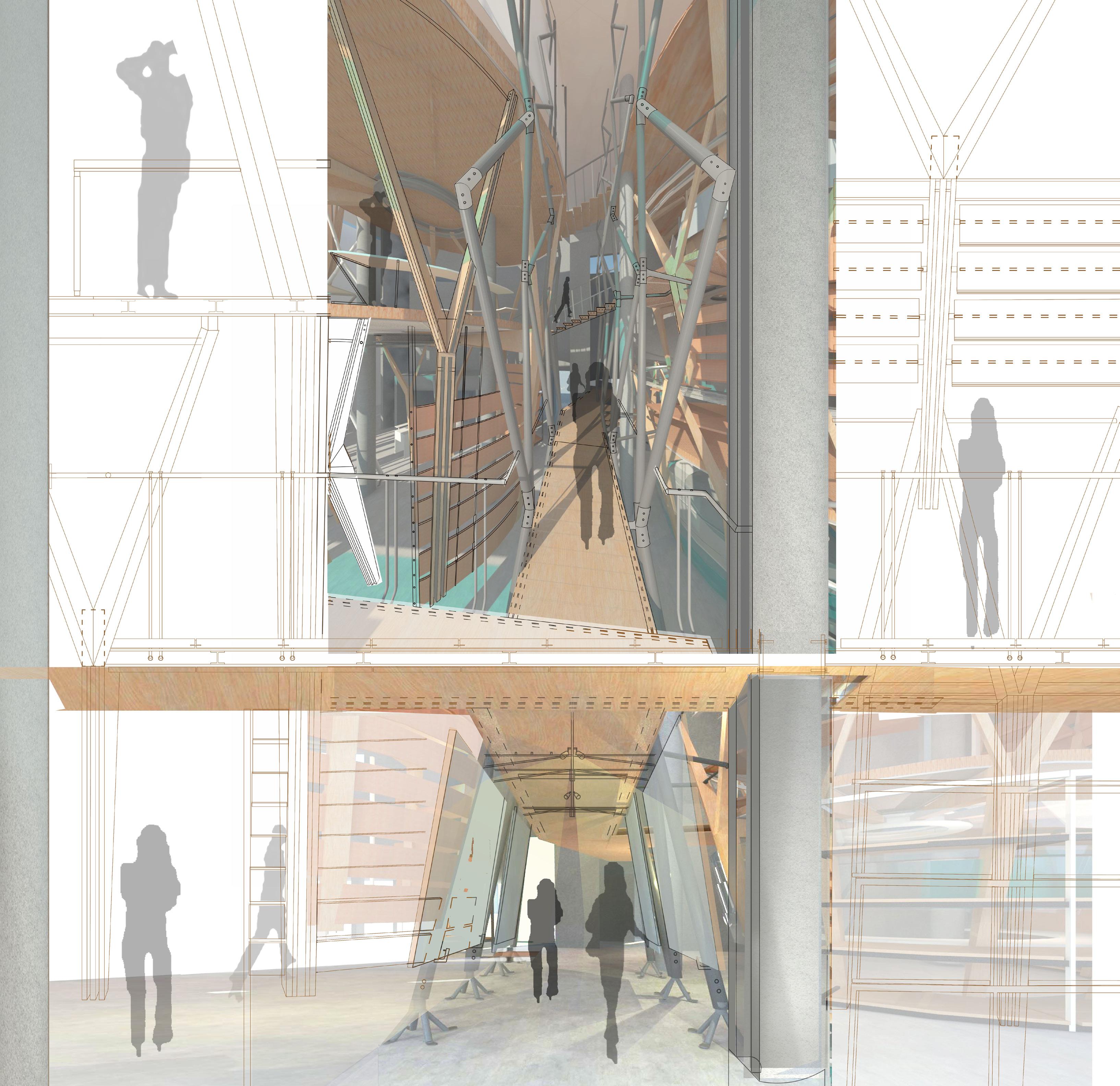
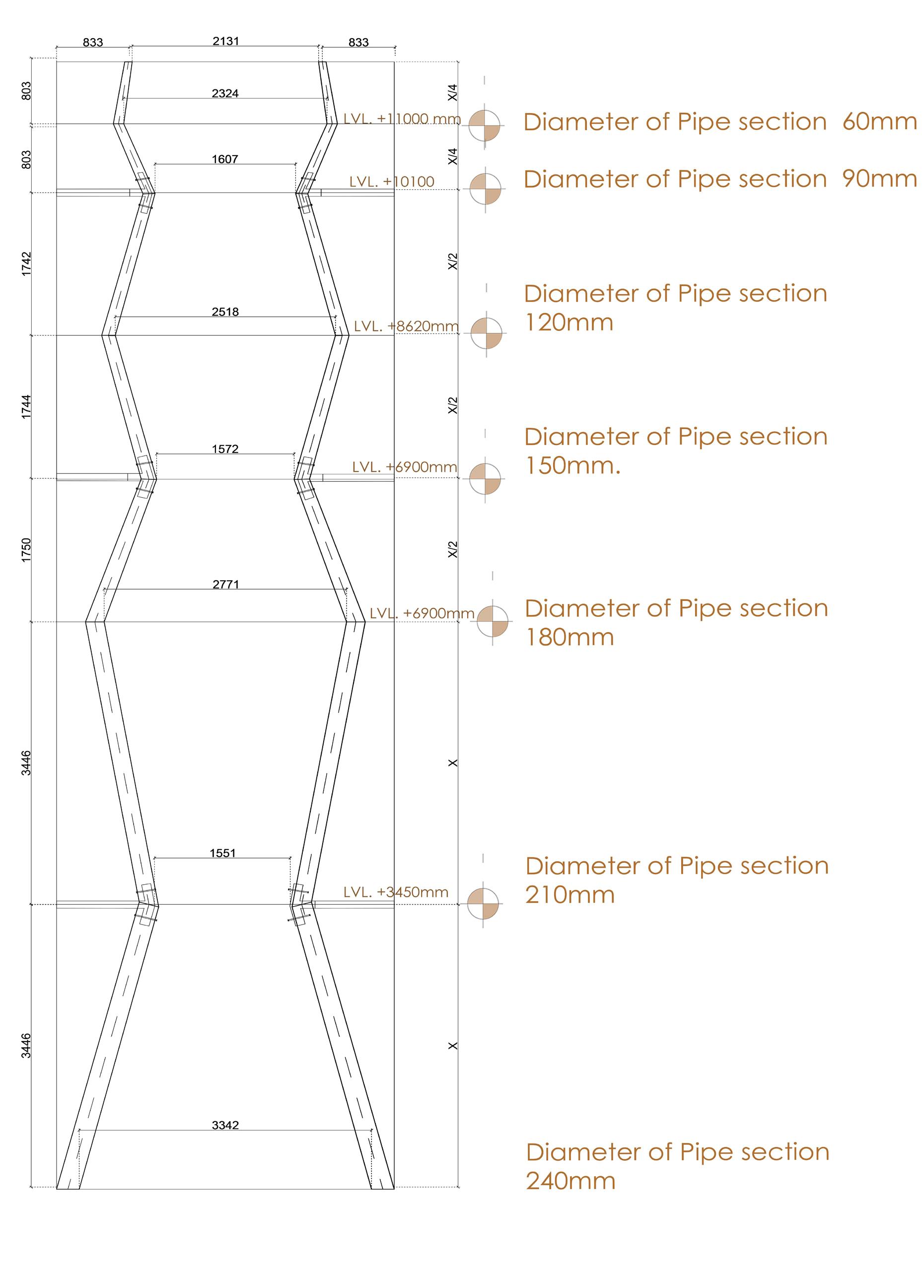
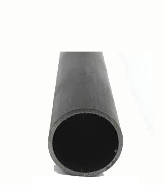
SS metal Round section wit dia 240mm to 60mm
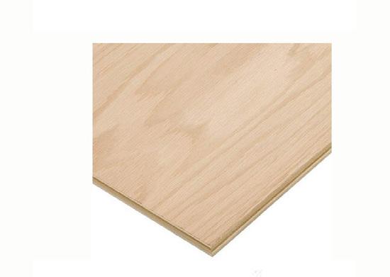
Ply wood 35 mm for flooring
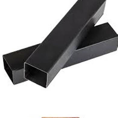
SS metal box section 45x45mm for Display
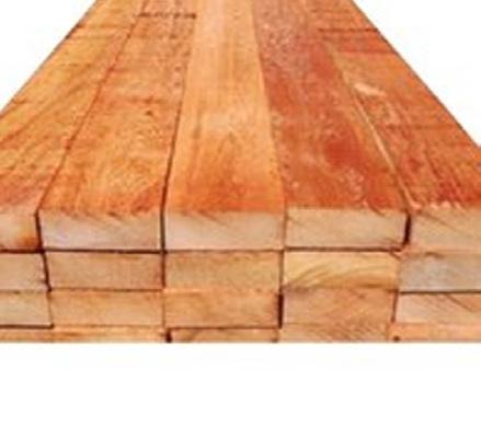
Cedar Wood for wooden compression member fo well skeleton.
SS metal rod 20mm dia for Railing
Metal
Metal Box Section 35mm x35mm)
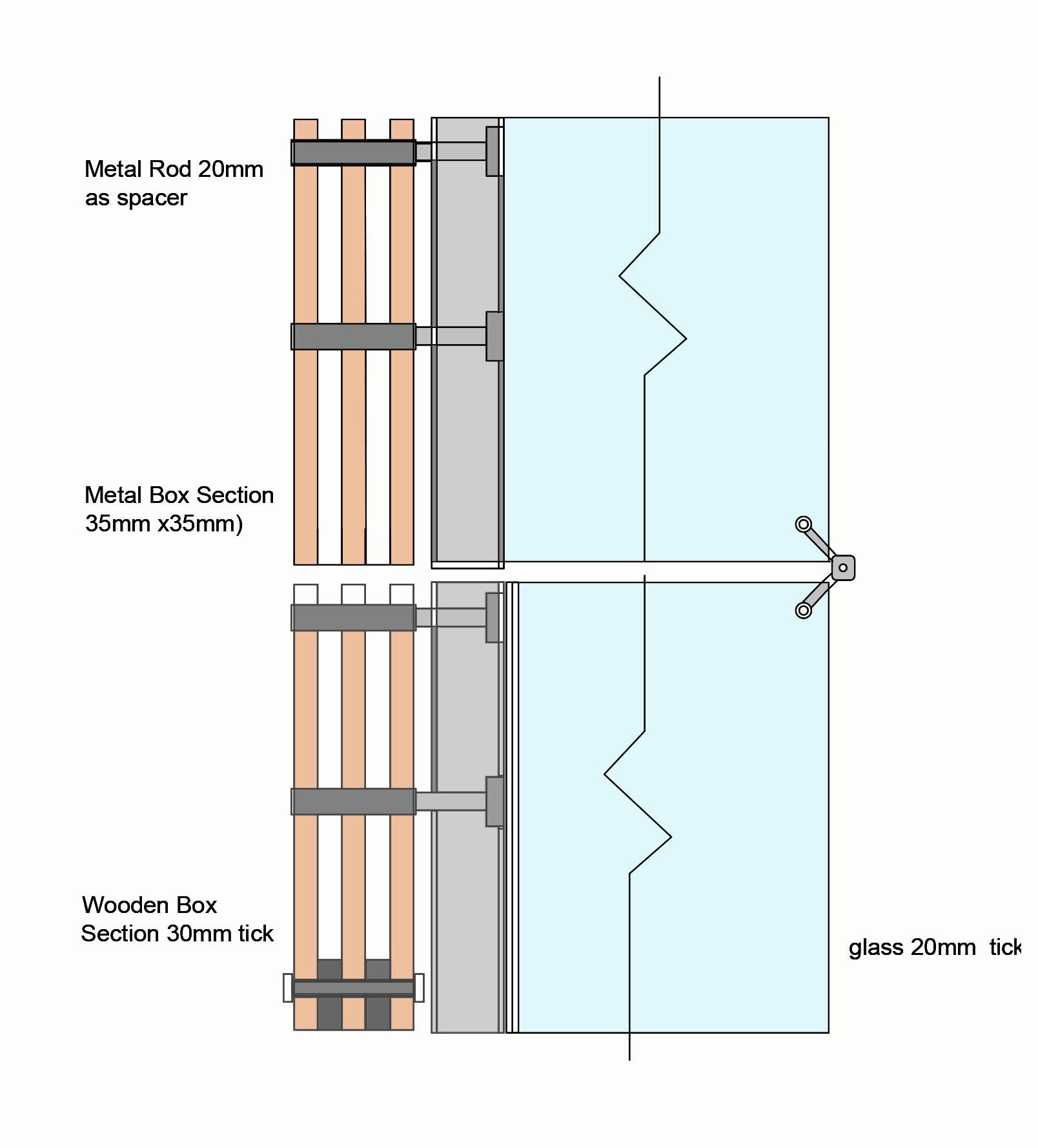
Wooden Box Section 30mm tick
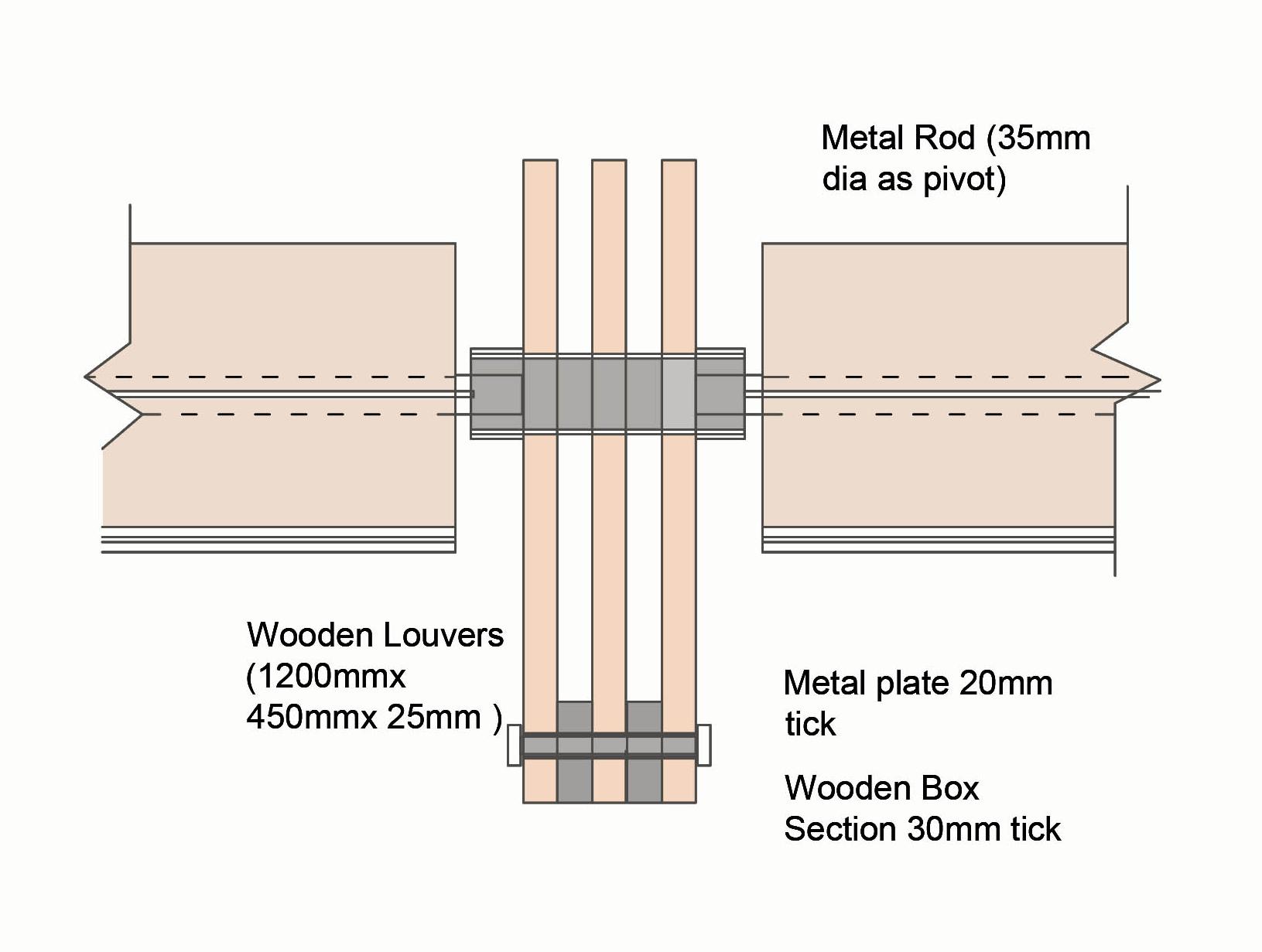
Metal
Wood (30mm tick)
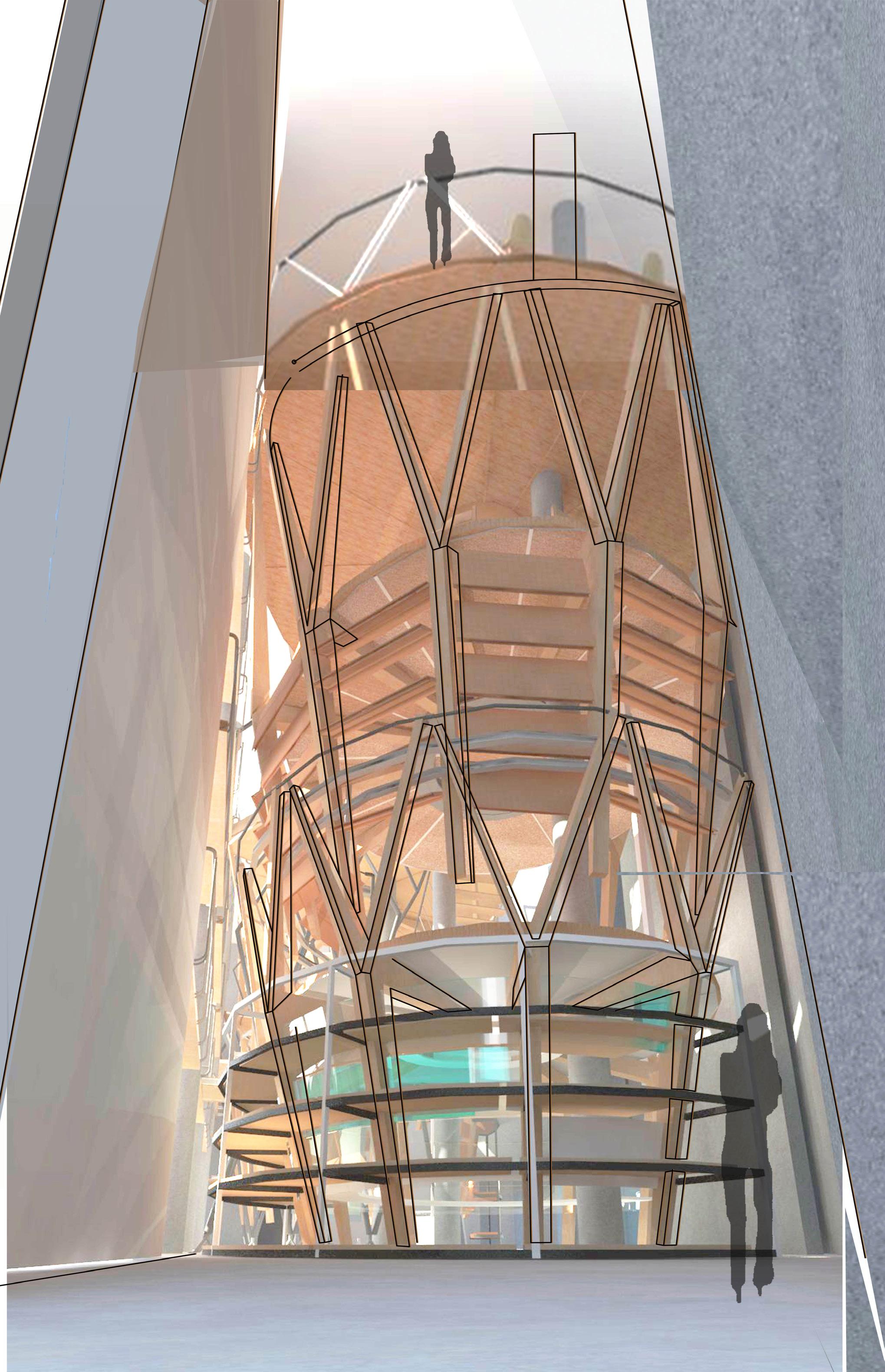
CIRCULAR PIPE 80 MM DIA AS JUNCTION FOR WELL WITH BRIDE
20 MM PLWOOD SANDWICh
I SECTION (80MM WEB ) 40 MM FLANGE sANDWIC BETWEEN PLYWOOD .
T SECTION WITh DOUBLE WEB (100MM) FLANE (100MM)
20MM DIA OLES FOR FIXIN CANTILEVER WOODEN BEAM WIT T SECTIONS.
I SECTION RINg hOLDINg CANTILEVER MEMBERS
I SECTION (150MM WEB ) 100 MM FLANGE CIrcular bent in 4 Quadrant.
Isonometric detail of junction of vertical conncection with floor (Well levels).
Detail A
SPACER BETWEEN COMPRESSION MEMBERS(40MM DIA x 160mm LENTL )
TENSION ROD (BETWEEN 2 SPACERS
SPACER BETWEEN COMPRESSION MEMBERS(40MM DIA x 160mm LENTL )
TENSION ROD (BETWEEN 2 SPACERS
WOODEN SECTIONS 20MM THICK
I SECTION (100MM WEB ) 50 MM FLANGE CIrcular bent in 4 Quadrant.
WOODEN SECTIONS 20MM THICK
I SECTION (80MM WEB ) 40 MM FLANGE FOR BRACIN TWO I SECTION
I SECTION (100MM WEB ) 50 MM FLANGE CIrcular bent in 4 Quadrant.
METAL GUSSET PLATE 45MM THICK BETWEEN WOODEN PLANKS
I SECTION (80MM WEB ) 40 MM FLANGE FOR BRACIN TWO I SECTION
WOODEN PLANK (tRIANULAR IN SAPE) 60MM THICK
METAL PLATE 25MM THICK
2.5X
WOODEN PLANK (tRIANULAR IN SAPE) 60MM THICK
WOODEN SECTIONS 60MM THICK
METAL PLATE 25MM THICK
WOODEN SECTIONS 60MM THICK
METAL GUSSET PLATE 45MM THICK BETWEEN WOODEN PLANKS x
Isonometric detail of junction of vertical connection of two same members of different voulme of wells.
B
4070
LVL. +11800mm
LVL. +11000mm
LVL. +10100mm
7901 2538
LVL. +8620mm
5194
LVL. +6900mm
LVL. +3450mm
Cedar wood 40mm tick
Tension cable 4 way Connector
Tension Cable (20mm dia)
Detail 1 Detail 1
Ply wood 35 mm tick
Double web T as floor and beam connector. Cedar wood 40mm tick Tension cable Connector
Logo for Project Well of Orchestrated Assembly Branching and Propagating in X - Y - Z Direction
