DEVANSHI PATEL SELECTED WORKS

DEVANSHI PATEL
22nd May 1998


Cincinnati, United States of America
+1 513-313-1561
devanshipatel22work@gmail.com
https://portfolio.cept.ac.in/student/patel-devanshi-piyush-ui4915
https://devanshipatel22wor.wixsite.com/devanshipatelworks-c
https://issuu.com/devanshi22work
https://www.linkedin.com/in/devanshi-patel-61785725a/
About me
“ ”
I firmly think that well-designed places have the power to revitalise the five senses that every livingbeing possesses. I try to visualise and design spaces that are uniquely impactful and experiential, yet let them stay rooted with traditional materials and methods that can embrace social and cultural context as well. I enjoy working on a junction’s detailing to enhance the user experience. I believe that to solve any design problem, focus on demand and the experience of the user matter the most, along with a funtional, strategic design solution.
2
Portfolio| Devanshi Patel
Education
University of Cincinnati
Master’s in Architecture (2023-2026) (currently pursuing)
CEPT University , Ahmedabad , India
Bachelor’s in Interior Design (2015 - 2020) (5 Year Undergraduate Program)
Hochschule fur Technik, Stuttgart, Germany
International Exchange Student (2018 - 2019)
Bachelor’s in Interior Design Program
Languages


Interests
Conceptualization
Research and Development of Craft and its Techniques
History of Art and Architecture
Expertise
Sketching
Visualization and Presentation
Communication and Mangement
Skills
Software Skills
Analytical sketching
Working with wood and Metal prototypes and Junctions
Architectural Research Writting
Work Experience
Junior Interior Designer
HCPIA Pvt. Ltd| Ahmedabad | 2021 - Present
Got an experience to work on a big government Project that to when the site is far away from the work place.Hierarchy and Management of Project becomes the key feature in order to work on a big Projects with time bound deadlines.
My scope of work included the following.
• Interior Tender packages of 5 buildings of Centra Visa Redevelopment Project, New Delhi (In a group)
• Central Vista Project, New Delhi ; Furniture Layouts and Furniture Presentations and Furniture Datasheets for Executive Enclave Buildings.
• Flooring Pattern designs and Good for construction document for Executive Enclave.
• Door Design representing traditional Indian style for Executive Enclave, Vice President’s Enclave and Prime Minister’s Enclave.
• Prepared Client Presentation of Interior Design Concept for Exective Enclave.
• Conceptual Presentations and development for 4 buildings of Central Vista Project.
• Research and development about the certain specifications of materials , Elements , Local craft techniques etc
• Working drawing of few Furnitures for mass production at factory.
• Created Mood boards and Material Boards for 5-6 projects.
• Handled the Executive Enclave project as a Sub Head. My task included management and communication between Architecture team and Internal Interior Design Team apart from working on the package.
• Executive Enclave comprised of 4 Buildings where 3 are 4 storey an one building is 2 storey.
Hand Skills
Spatial Planning
Design Detailing
Conceptual Representation
3
Hindi Gujarati A Ä German English
AutoCAD 2D and 3D Sketchup Microsoft Office Adobe Indesign Adobe Photoshop V-ray Enscape Vector works Rhinoceros Grasshopper Adobe Illustrator Hand Drafting Hand Rendering Sketching Model Making Working with Wood Working With Metal Fabric Tye and Dye and Weaving Working with Bamboo Fabric TyE and Dye
1 Curriculum Vitae 2
10
Work Experience
Junior Interior Designer
Projects 3.14| Ahmedabad | 2020 - 2021
• Interior Layouts for Printing Press readapted to Pet Hospital.
• Research and development of a space requirement , equipments and Safety Standards for designing a Pet Hospital.
• GFC Furntiture Drawings of a Residential Project.
• Headed a 350 sq feet readaptation project. The project was to design a branding store for a young customized Furntiture and Rugs brand.
• Mood Boards , Client Presentations, 3D Modelling, Interaction with execution agency were key learnings while working for Pet Hospital and Retial Shop Project.
Internship
Xia Works | Stuttgart , Germany| 2019(4.5 months)
• Commercial Banquet Ceiling design Project for a hotel in Munich.
• From Conceptual development , Construction drawings, 3d modellling, Material Procurement, Interacting with vendors etc were a part of my tasklist while working on a banquet Ceiling Design Project.
• Architecture Drawings of a Outdoor Garage cum Barbeque Place.
Internship
ParkRaum| Stuttgart , Germany | 2018 (Freelancing)
• Worked on conceptual development of a healthcare retail shopalong with making 3d Models for visualization , Matrial Selection and attending site visits with Head Project Manger.
• 3d Models and Furniture drawings for Exhibition display units for a popup store of a Healthcare company.
Internship
Umang Shah Architects| Ahmedabad | 2018
• Worked on a residentail project in Ahmedabad from Concept, to Furniture Layouts , Furniture Detail Drawings, Kitchen drawings, Electical Layouts , Material Selections , Prototype drawings etc.
• Got a chance to attend client Meetings and Site Visits during Execution Stage.
Academic Research Writting
Transition of traditional Iraqi Courtyards of Bagdadh : Study through traditional Material, Style , Environmental and Social Influences.
Re-adapting Vernacular aspects into modern Architecture
: Discussion through works of Renzo Piano, Kengo Kuma, Tadao Ando and Charles Correa
Ancilliary
Documentation and Appreciation of Heritage of Ahmedabad
Exploring Fabric Processes
The Making of Goan Houses
Himalayan Raw Architecture
Accomplishments
Selected for an International Exchange programe at HFT, Stuttgart at Germany for one semester on Merit Basis in 2018.
Awarded the Best Capstone Project Award at CEPT University Level in 2020.
Awarded the Gold Medal under the Best Final Year Project Category by GICEA (Gujarat Institute of Civil Engineers and Architects )at State Level in 2021.
4
Curriculum Vitae
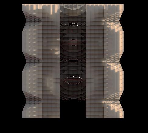
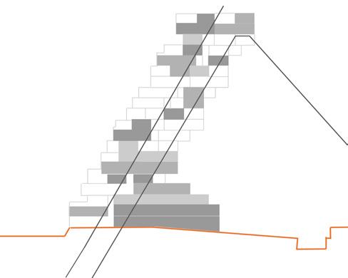
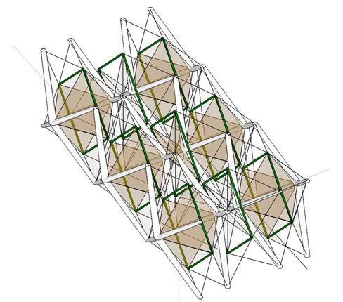
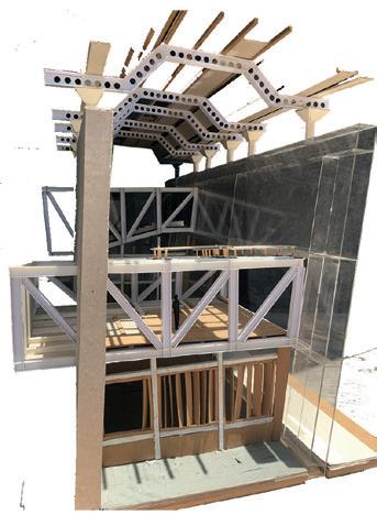
5 Table of Contents
of Contents.... 01 02 03 04 05 06 07 08 P & G: Office for Future
House: Reading between lines
Table
Thin
Facade /Wall section design Misbehaved Tectonics Exhibition space Design XYZ of ABC: Assembly based construction Interpretation center
Hands on Making
6 P & G: Office for Future
01
P&G OFFICE FOR FUTURE
Academic Project (Fall 2023): Reimaging the future of the workplace through adaptive reuse
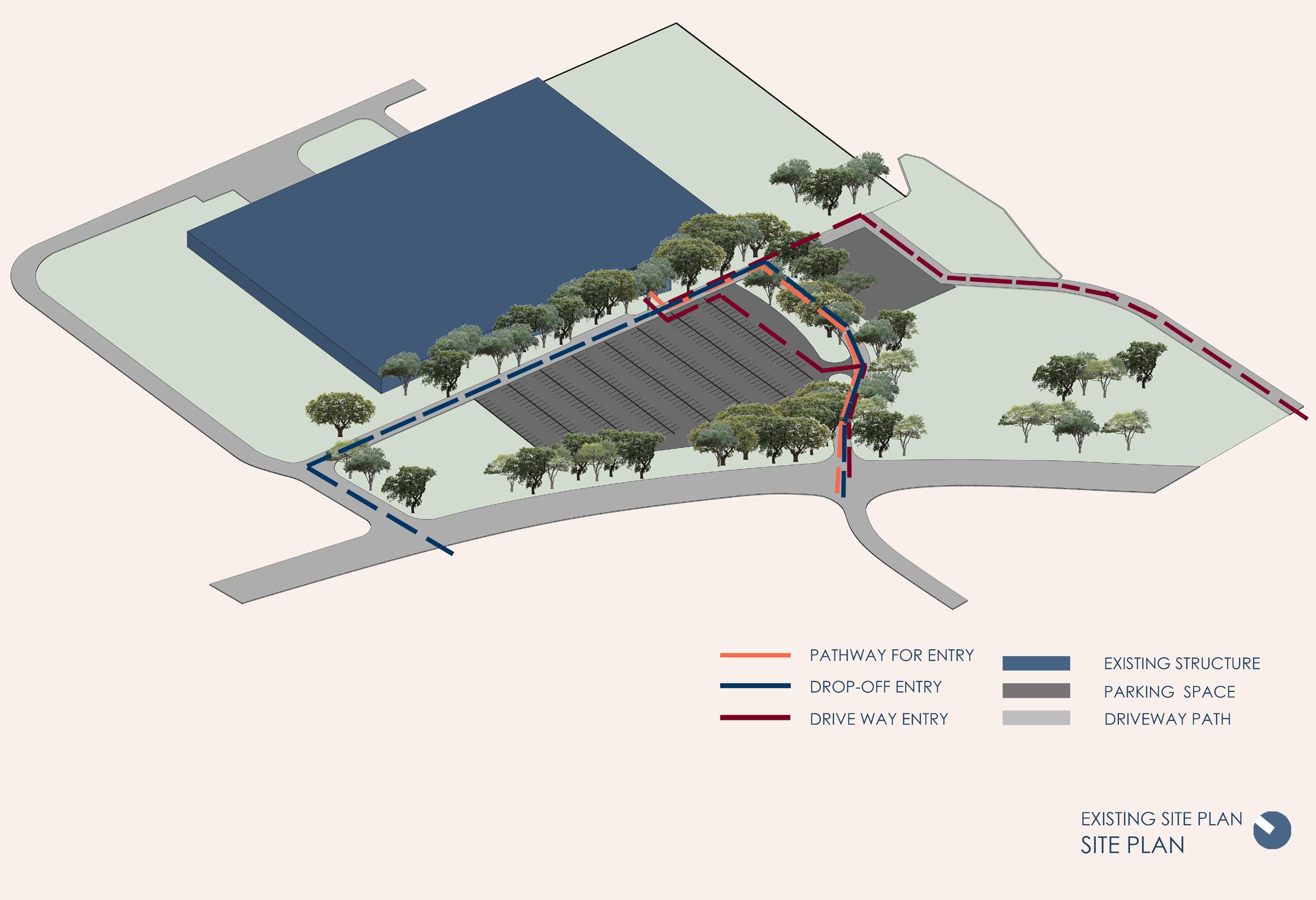
Location: 8256 Union Centre Blvd, West Chester Township, Ohio Area: 3,74,400 sq feet
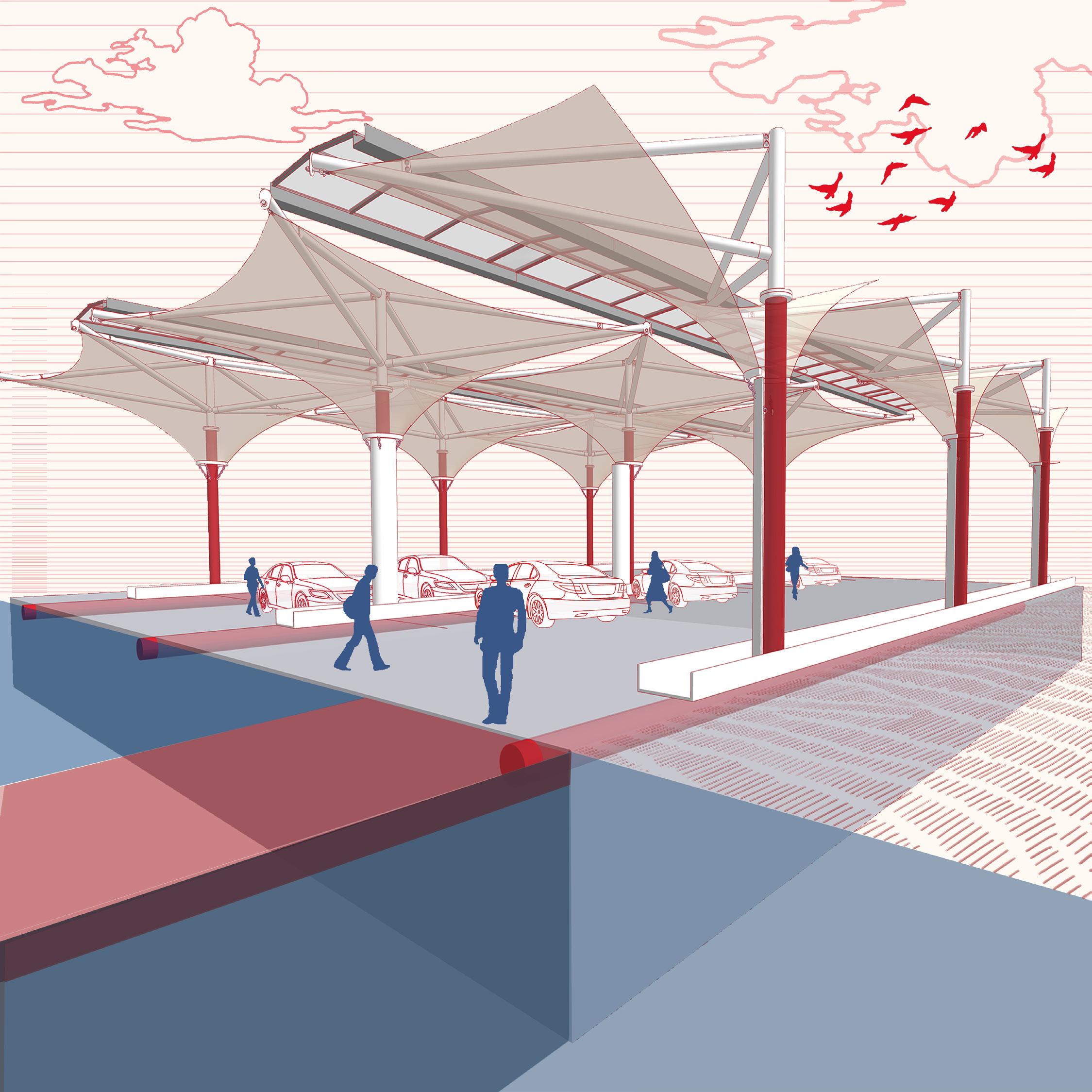
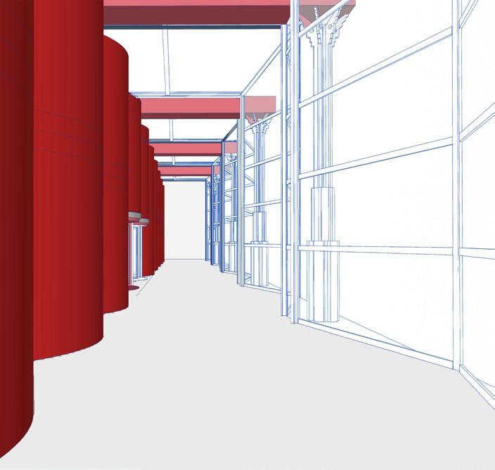
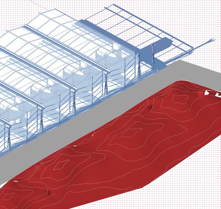
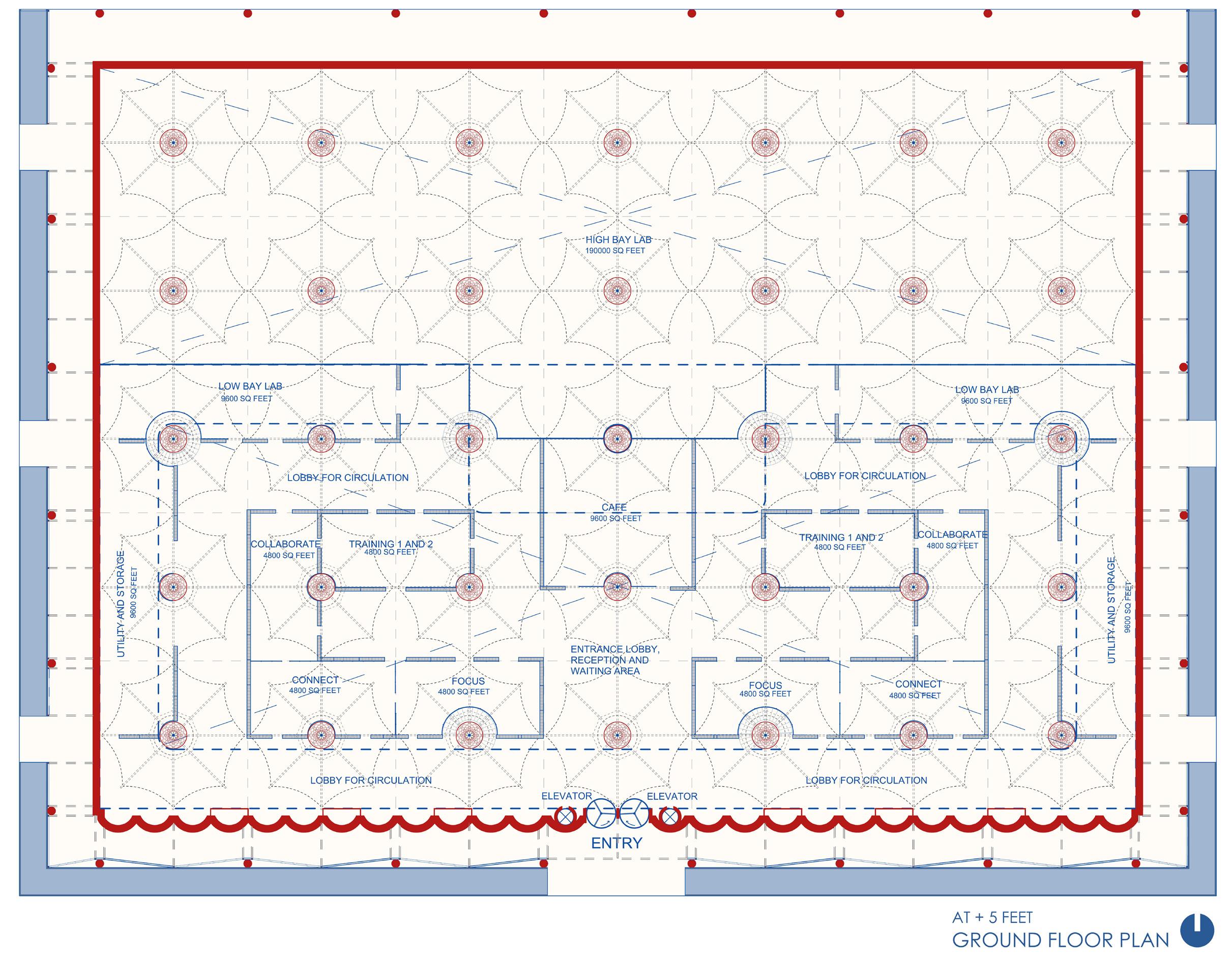
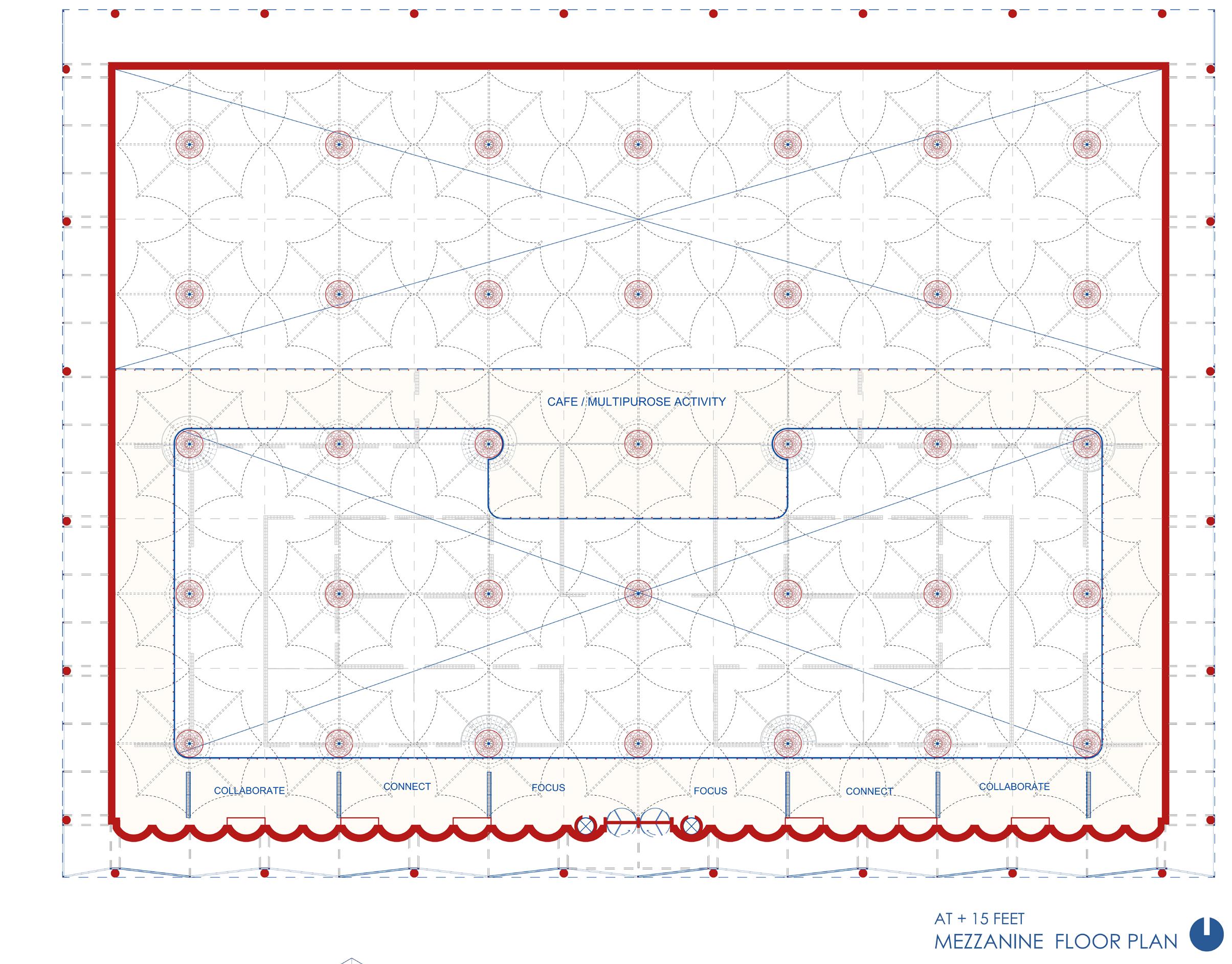
Office design for P and G revolves around the core principles of axis symmetry and the transformative power of natural light. Considering light as an important criterio to readapt the work space, roof plays the role of the a dynamic element, channeling light strategically into work areas, meeting rooms, and communal spaces. This concept emphasizes the duality of elements in your office design, highlighting the balance between solidity and transparency, function and aesthetics, and day and night functionality.
“The space creates an experience curated to optimize productivity, foster collaboration, and enhance wellbeing through the symbiotic relationship between design, light, and function.”
7
P & G: Office for Future
8
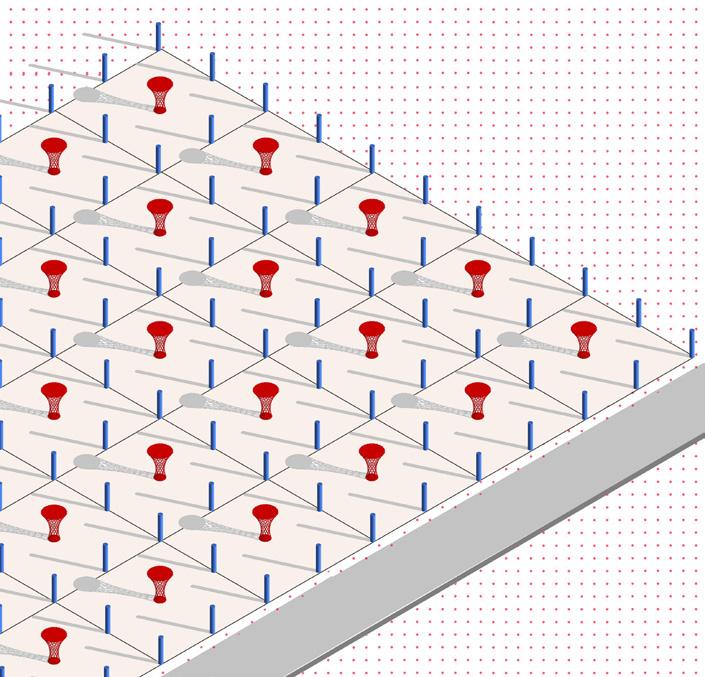
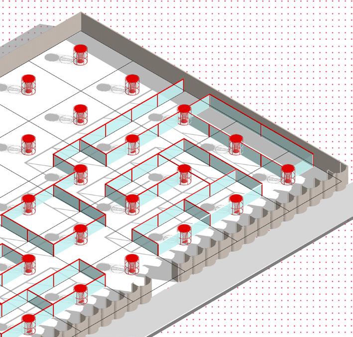
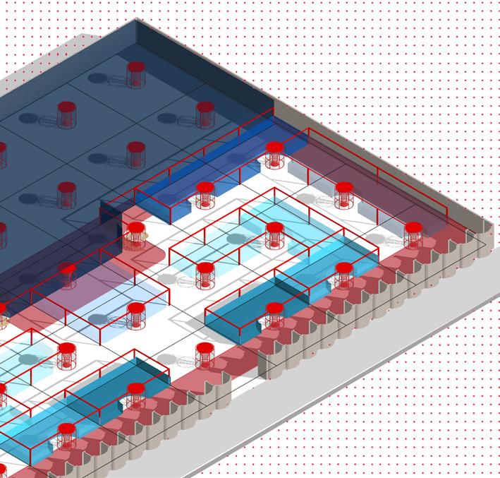
Existing Columns Proposed Columns Glass partion walls Ground floor and Mezzanine level plane P & G: Office for Future
POINT LINE PLANE
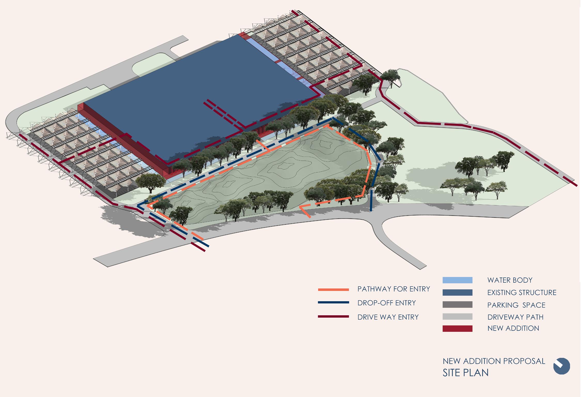
Site's emphasis on symmetry, axis, and the incorporation of contours in the front presents a unique opportunity to blend these features into an engaging office space design.
RELATION BETWEEN INTERIOR VS EXTERIOR
9 P & G: Office for Future SEMIOPEN CIRCULATION SOLID VS TRANSPARENT COUNTOURS AS RELATION BETWEEN SITE VS BUILT FORM
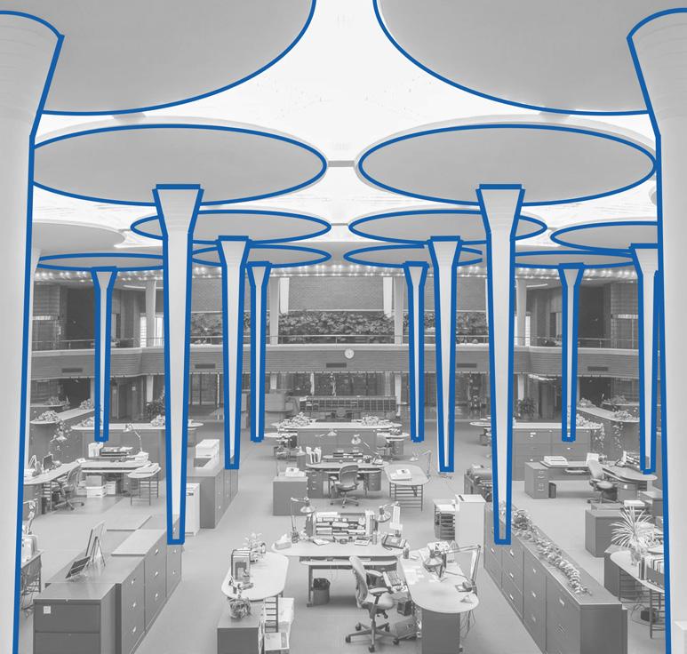
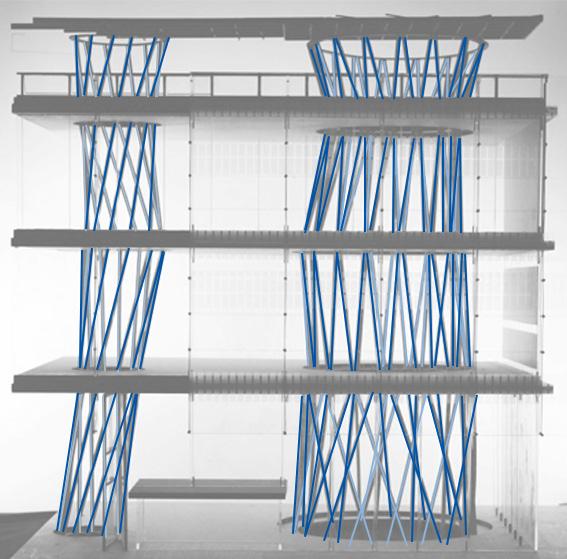
Columns of Sendai Complex
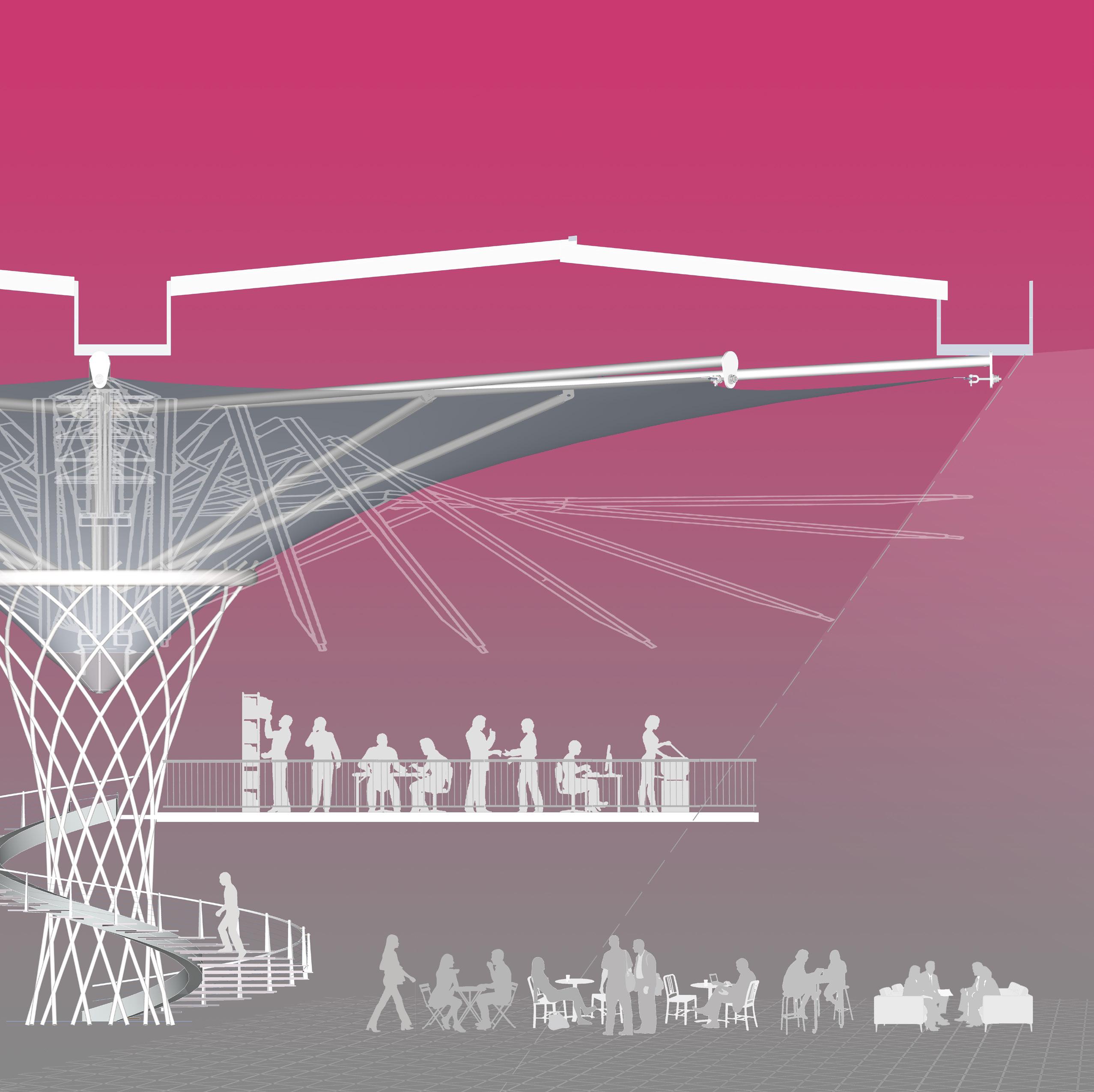
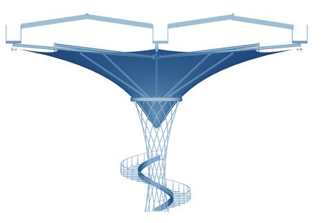
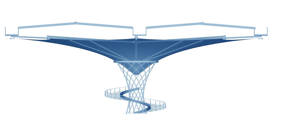
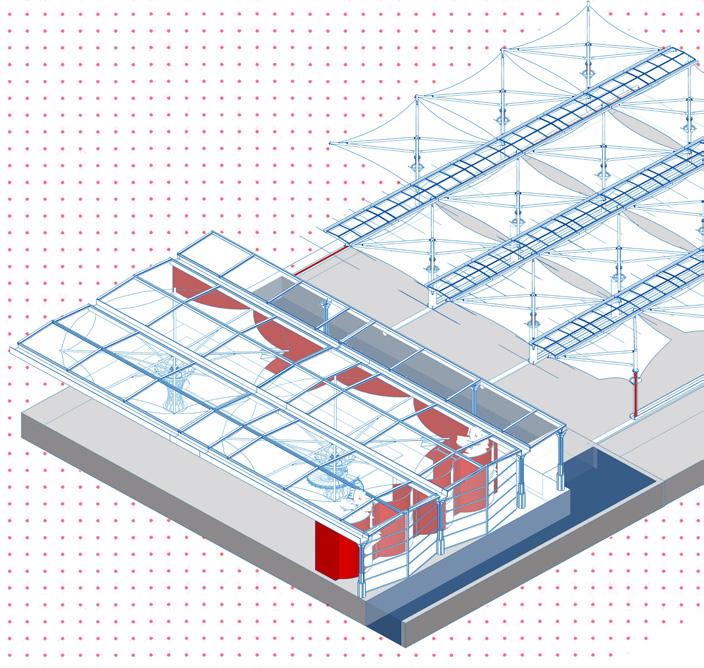
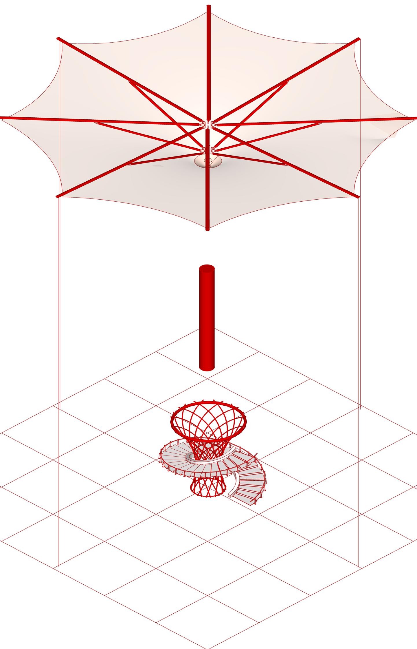
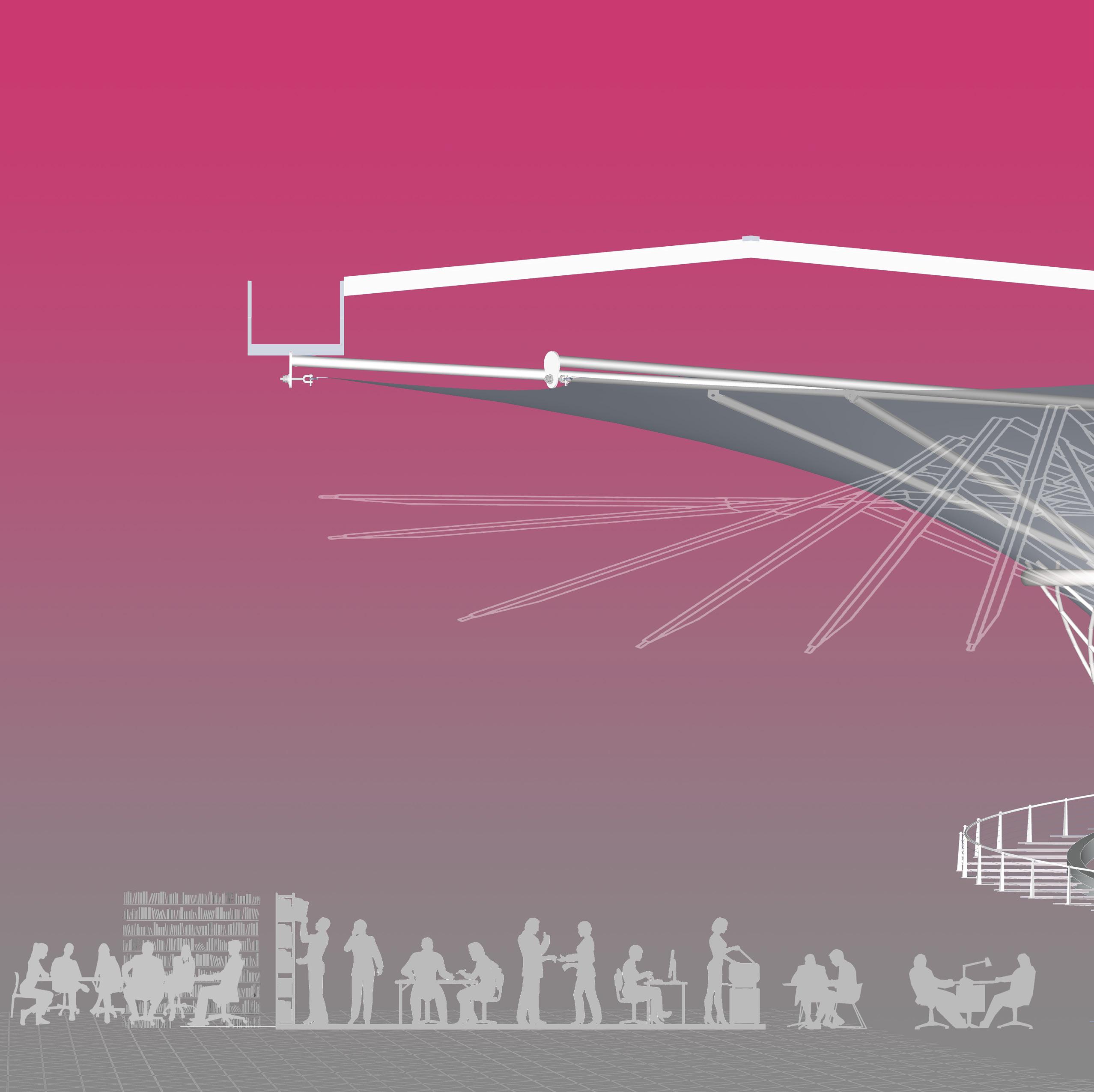
Convertile umbrella canopy as a shading/ light control element
Existing site column
Proposed multifunctional column
ELEMENTS BORROWED FROM THE PRECEDENT’S STUDY
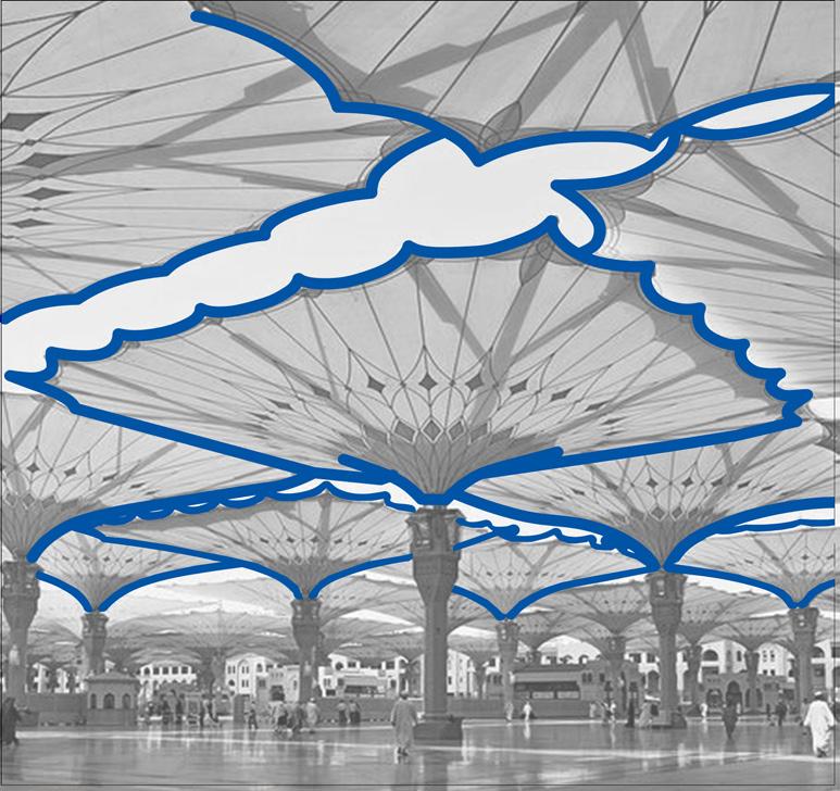
Drawing inspiration from architectural marvels such as the Johnson Wax Museum's triple-height columns, the versatile utility columns reminiscent of Sendai serve a multitude of functions, including HVAC and staircase integration. Similarly, the convertible umbrellas, echoing the design ingenuity of the Medina Mosque, dynamically adjust to varying levels of direct sunlight, exemplifying adaptability and innovation.
10
Umbrella at Masjid Nawabi Mosque
Johnson Wax Headquaters
P & G: Office for Future
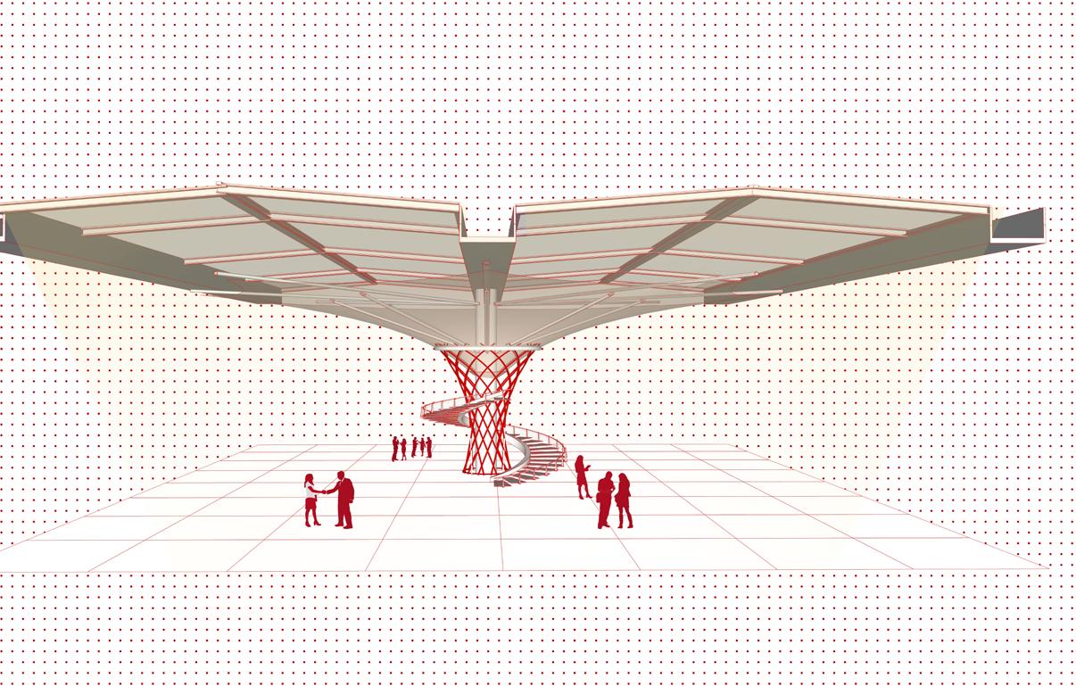
INTERIOR UMBRELLA EXTERIOR UMBRELLA
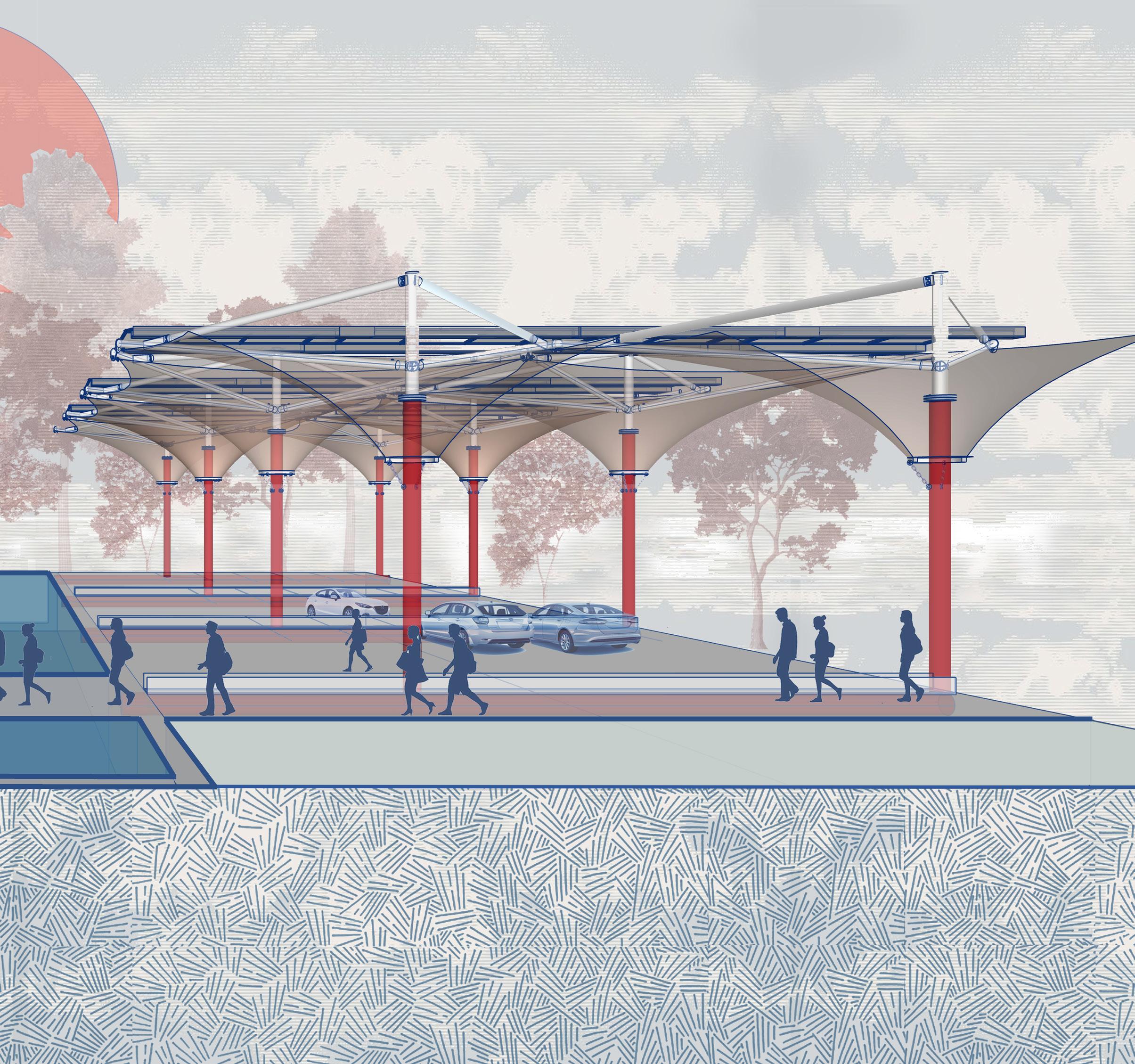
Exterior canopy serving as a parking space / with roof incorporated with solar panels and a rain water harvesting system
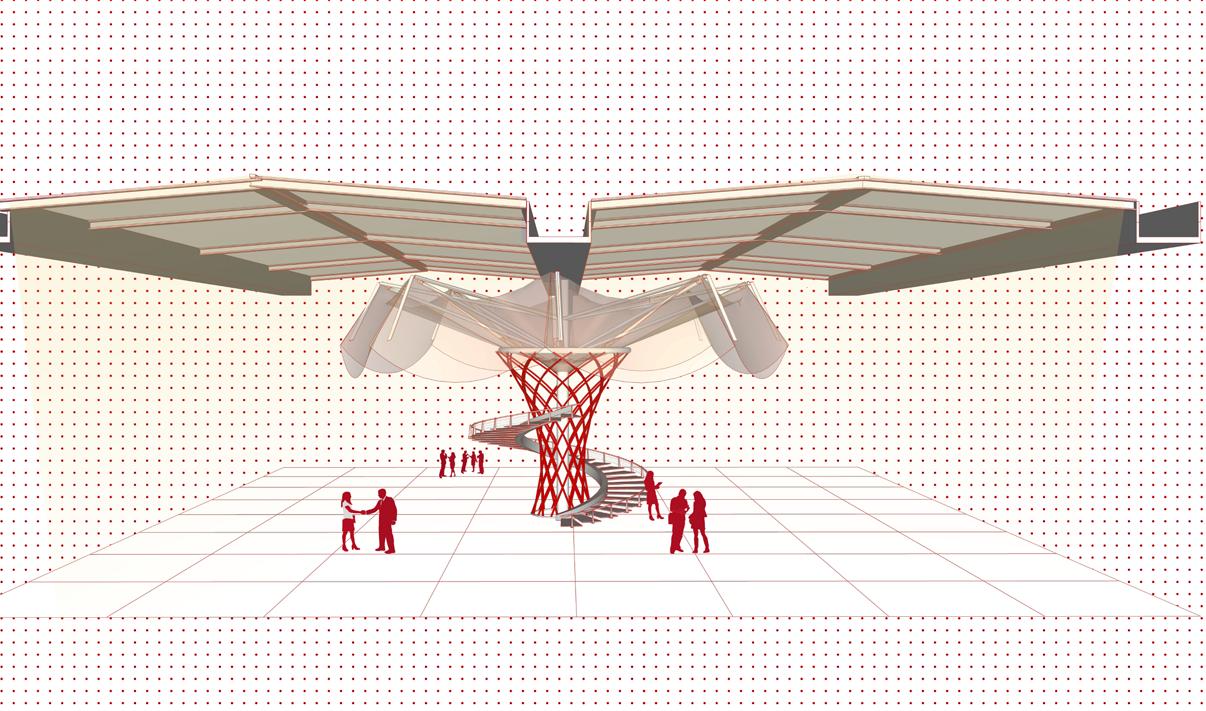
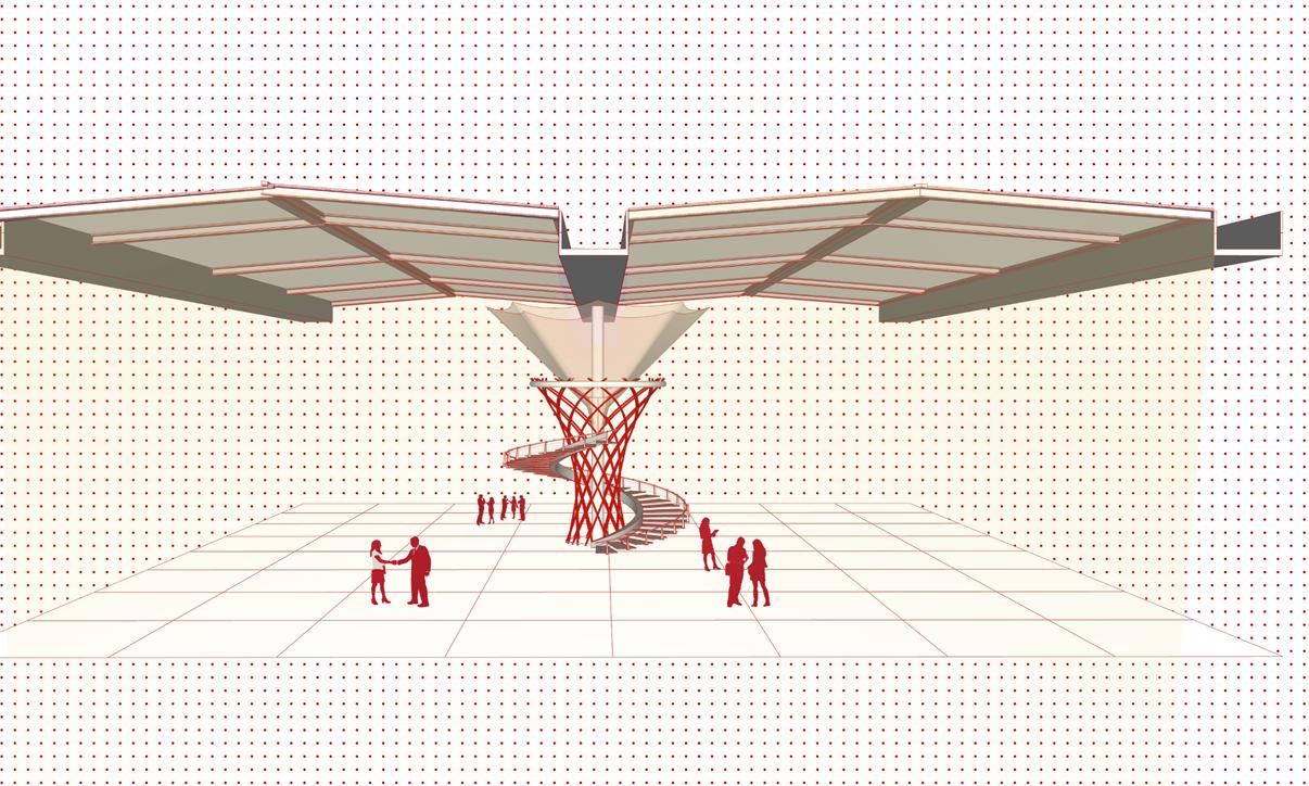
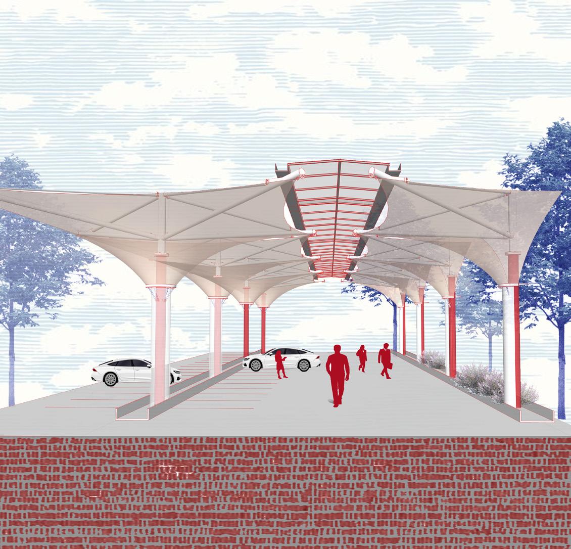
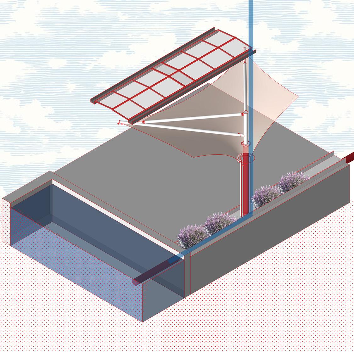
Water Pond
Rain water collection
11 P & G: Office for Future
1. OPEN CONDITION
2. SEMI-CLOSED CONDITION
3. FULLY CLOSED CONDITION

12 P & G: Office for Future

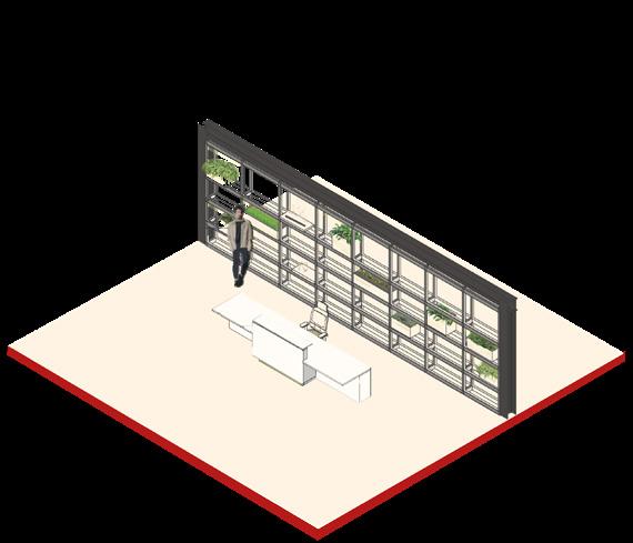
INTERIOR PARTITION
13 P & G: Office for Future
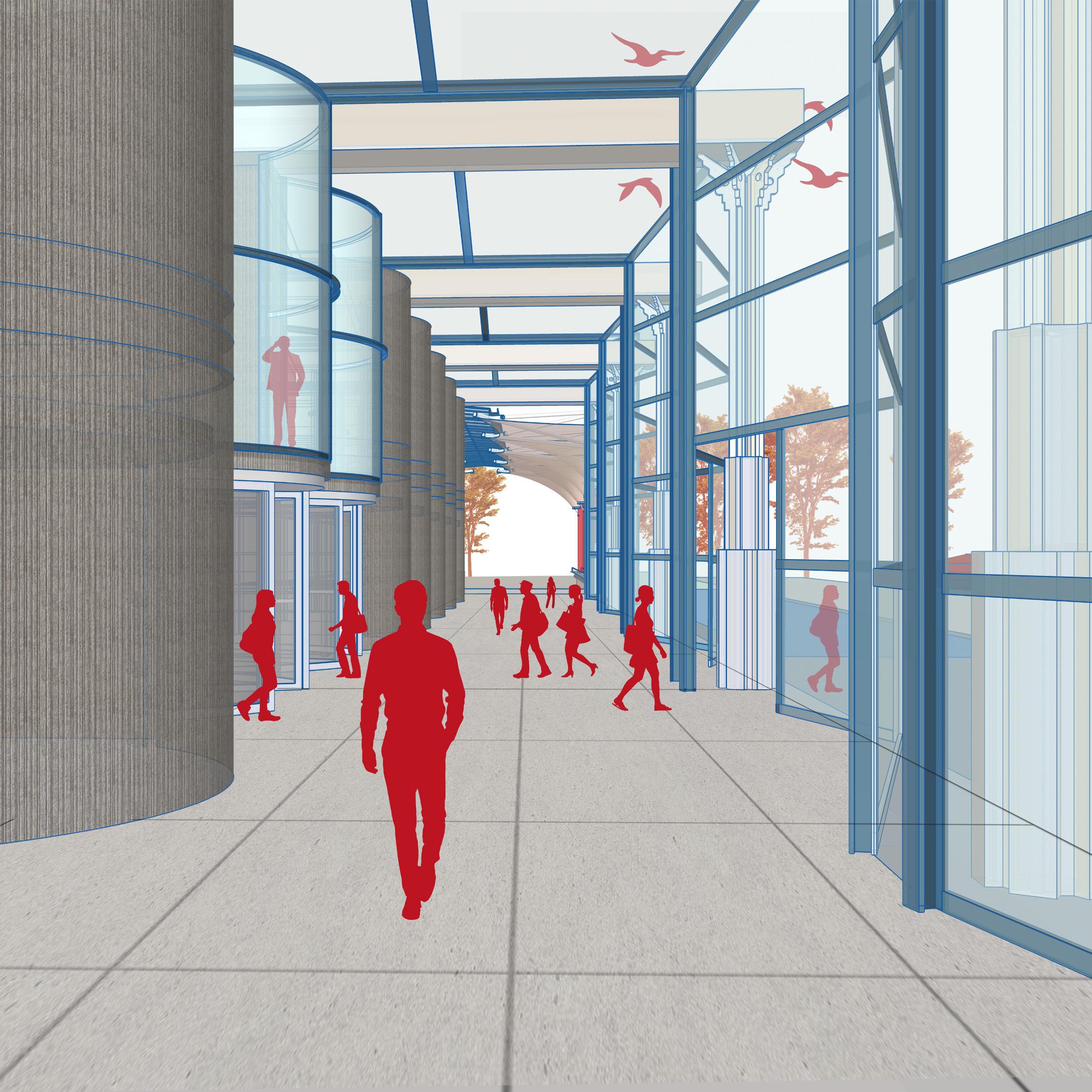
Facade Design
Relation between Interior - Exterior
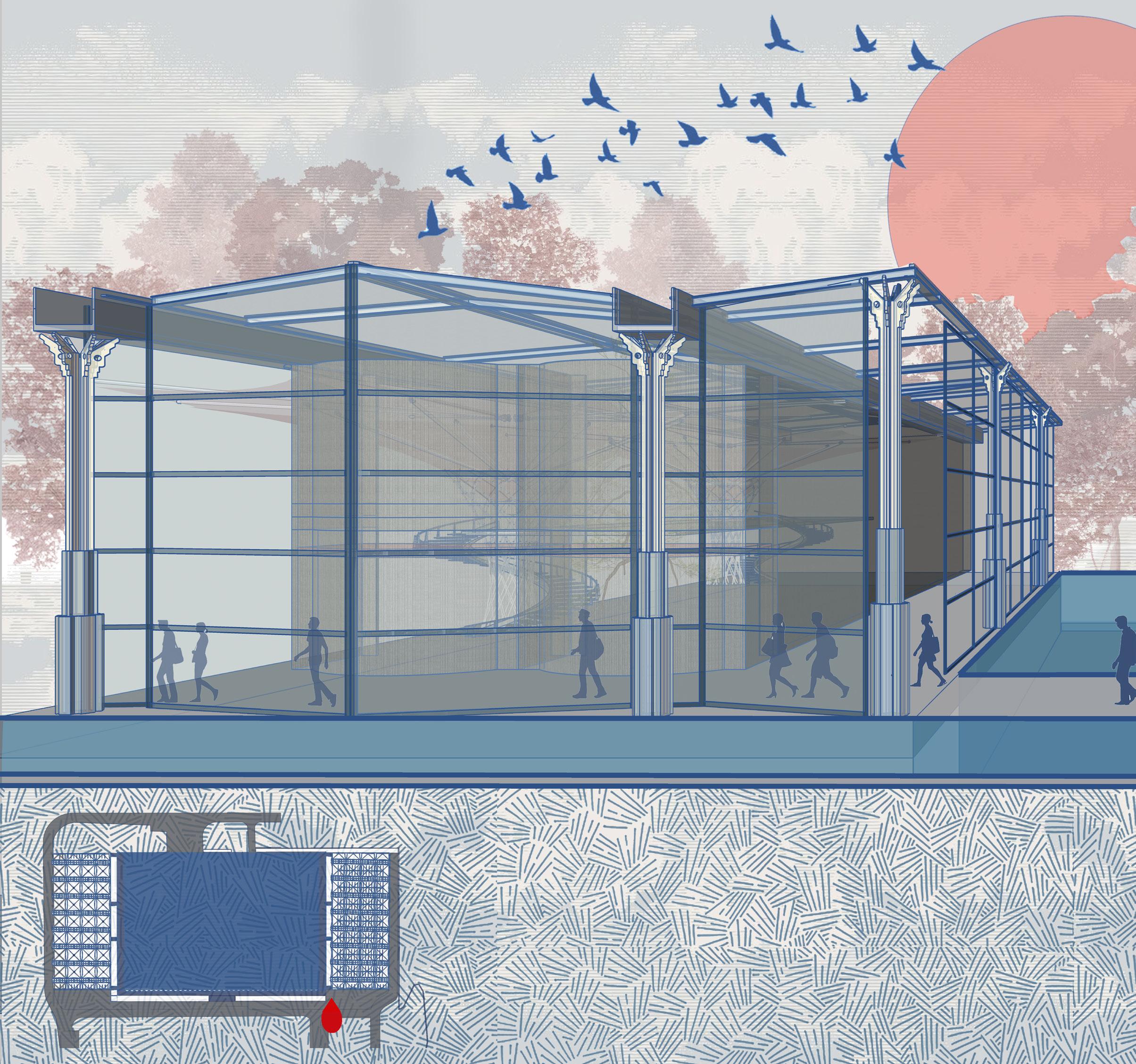
Following the concept of solidity and transparency , a solid concrete core forms the heart of the structure, providing stability, privacy, and a sense of groundedness. Embracing this core is a striking glass envelope, serving as a dynamic interface with the external environment.
14 P & G: Office for Future
Facade Design
Relation between Interior - Exterior
A view of the facade from the exterior through countors (designed as a hangout/ breakout place)
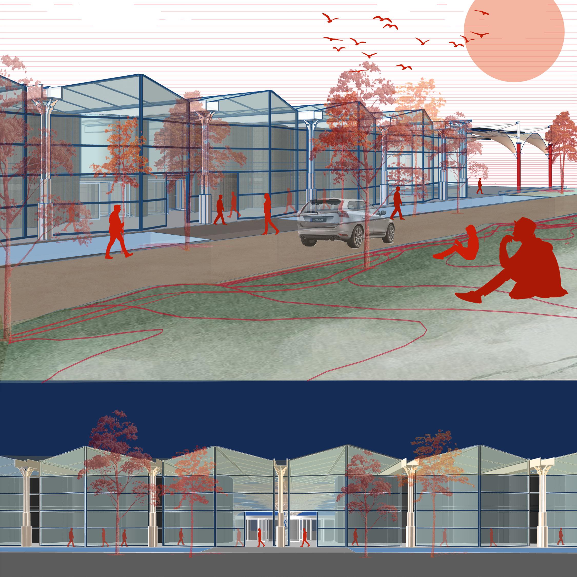
Night view showning illuminating glass box and solid concrete walls.
15 P & G: Office for Future
16
P & G: Office for Future
Glass Facade
Water feature serving of rain water harvesting
17 P & G: Office for Future
EXTERNAL SECTIONAL PERSPECTIVE serving the concept harvesting Column of External umbrella serving the purpose of a pipe to collect rain water Solar panels
“Architecture is an art of how to waste
18 Thin house : Reading between lines
PHILIP
space” -
JOHNSON
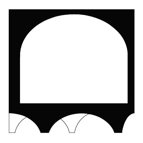
Vault House Thin House
Academic Project (Spring 2024): Precedent study for Thin House
Location: Oxnard United States
Area: 3600 sq feet
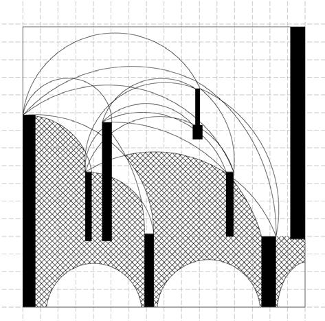
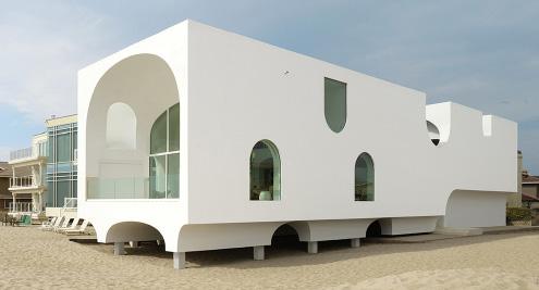
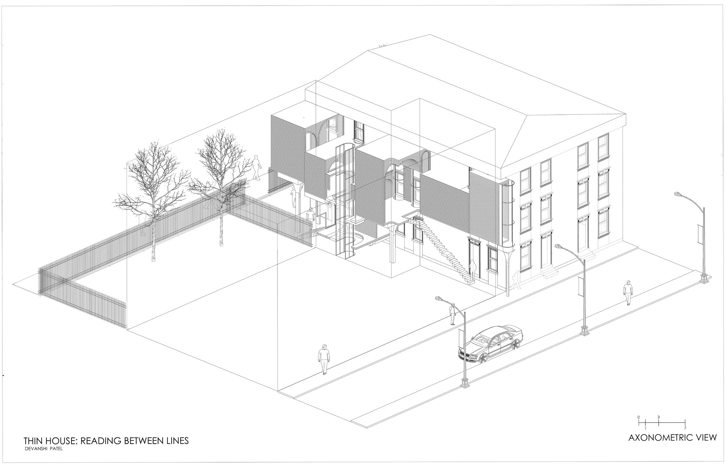
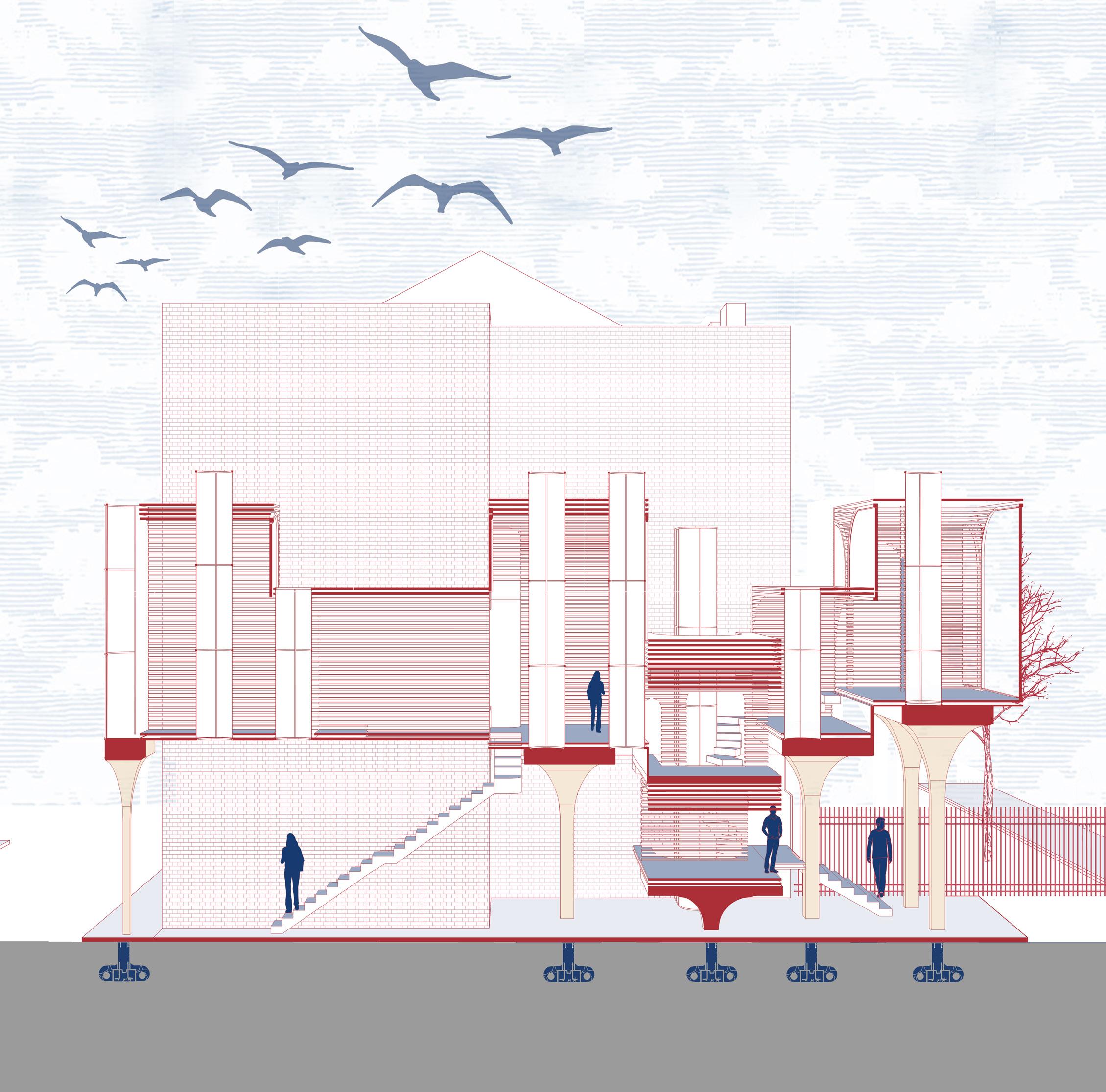
The Thin House project draws inspiration and concepts from the Vault House precedent study, particularly in its utilization of unidirectional vaults. While maintaining the essence of vaulted spaces, modifications are made to the construction assembly. Horizontal planks are incorporated into the exterior framework, creating a play of negative and positive spaces that facilitate visual connectivity, even from the furthest reaches of the house.
Additionally, the project takes into account the existing site conditions, ensuring minimal disruption to the ecology while leveraging it to enhance the functionality of the Thin House through optimal light distribution.
19
Thin house : Reading between lines
02
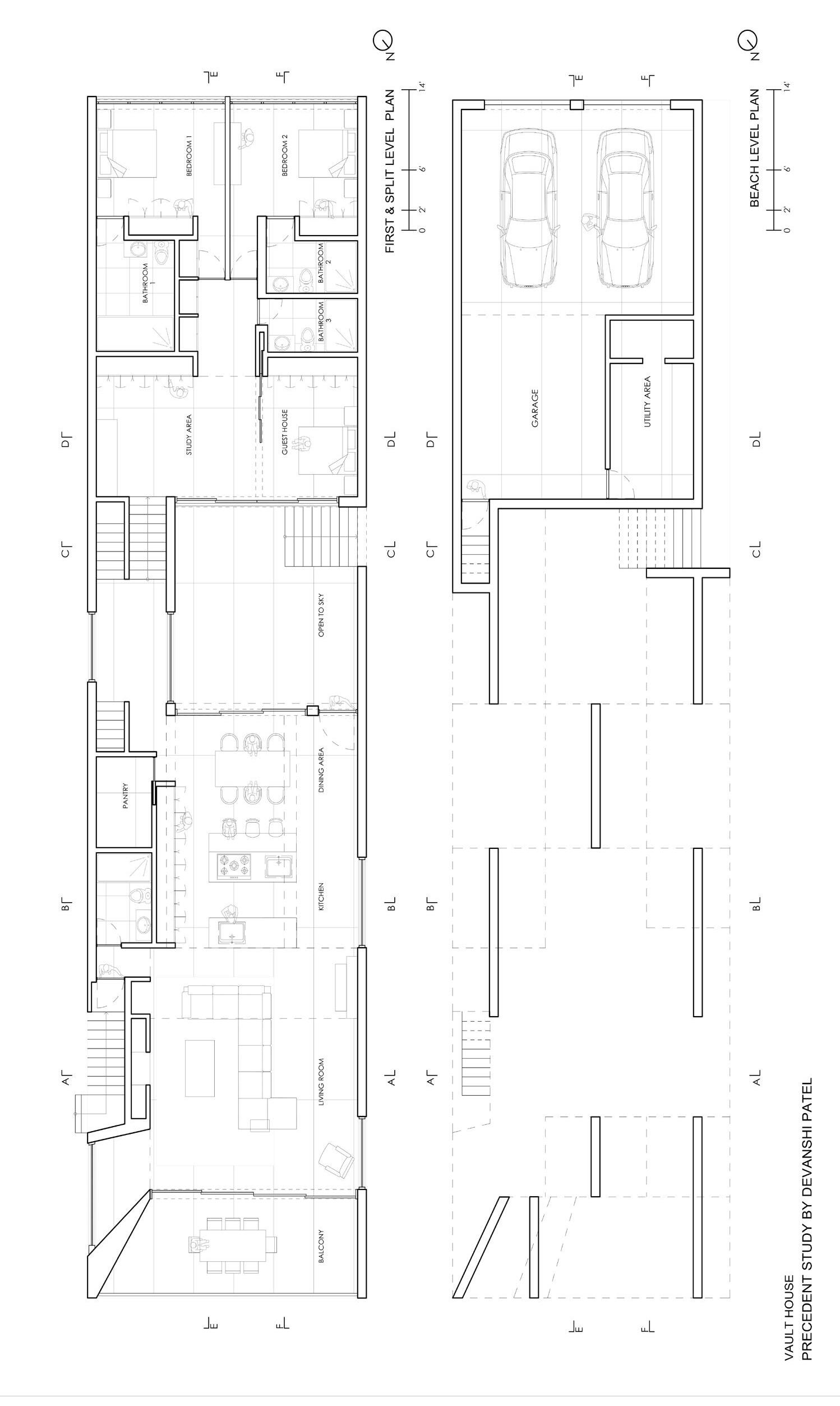
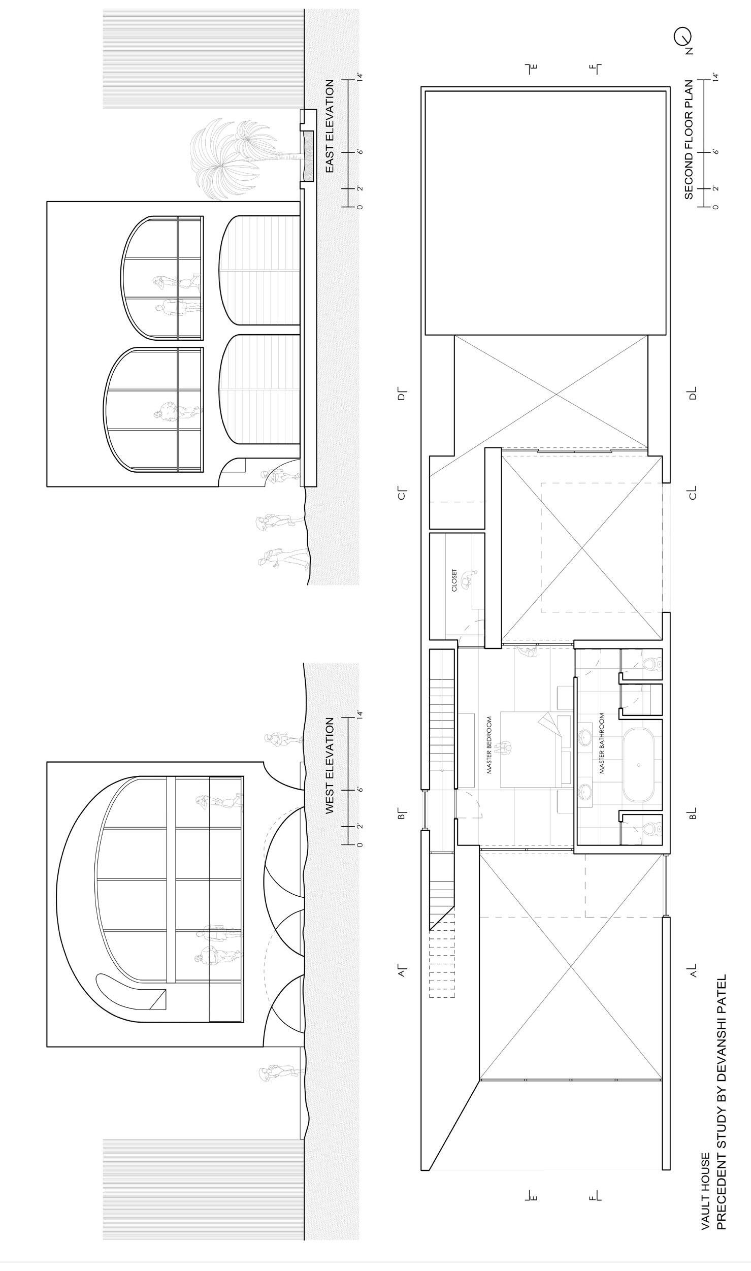
Thin house : Reading between lines Beach level plan First floor plan Second floor plan
Horizontal view
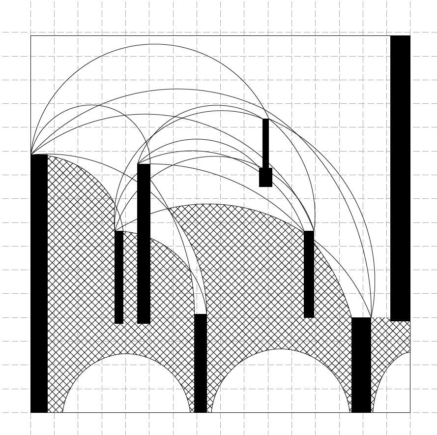
Black vertical members represent the solid structural memebers which obstruct the view from rear of the house tofront and white represents the clear vision
Axial Vaults
X , Y and Z directional vaults /openings
Linear Segmentation
Segmenting the vault house with the change in vault shape for each function of the house
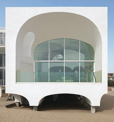
Vaulted Volumes Directional Transparency
Vault House _ Johnston Marklee_Parti Diagrams
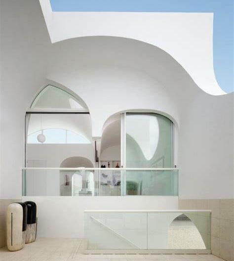
The building, despite its basic rectangular shape, features arched windows and recesses punctuating its volume from all angles. This design element is echoed inside, where vaulted doorways, rooms, and corridors create a continuous motif, culminating in a sweeping view of the beach and ocean.
By arranging stacked and unidirectional vaulted rooms within a straightforward rectangular structure, the parallel alignment of these rooms serves to enhance and extend the oceanfront vista. Adhering to local regulations, the house is elevated two meters above the sand and designed to collapse in the event of a tsunami, resulting in a split-level two-story layout with a garage tucked underneath at the rear.
A welcoming arched entrance guides visitors through a central courtyard, allowing natural light to permeate the interior while subtly dividing the living areas at the front from the bedrooms at the rear.
21 Thin house : Reading between lines
UNDULATING VAULTS DIRECTIONAL TRANSPARENCY AXIAL VAULTS DIRECTIONAL TRANSPARENCY VOID VS VOLUMES LINEAR SEGMENTATION AXIAL EXTRUSION FUNCTION FRAGMENTATION VAULTS VOLUMES MAXIMIZED OPEN VOID DEVANSHI PATEL VAULT HOUSE LIGHT AND FUNCTION FRAGMENTATION UNDULATING VAULTS VALUTED VOLUMES DIRECTIONAL TRANSPARENCY OFFSETED VOLUMES AXIAL VAULTS HORIZONTAL VIEW VAULT HOUSE DEVANSHI PATEL VOID VS VOLUMES LINEAR SEGMENTATION AXIAL EXTRUSION FUNCTION VAULTS VOLUMES MAXIMIZED OPEN VOID DEVANSHI PATEL VAULT HOUSE
Thin house : Reading between lines
HORIZONTAL VIEW OF SIGHT VAULTED VOLUMES LINEAR SEGMENTATION
CUBOIDAL VOLUMES AND SKYLIGHT VAULT
CIRCULATION
COPY AND MIRROR OF UNDULATING VAULTS (SECTIONAL VIEW) DEVANSHI PATEL
DIRECTIONAL TRANSPARENCY
STAGGERING LEVELS ALIGNMENTS
THIN HOUSE: READING BETWEEN LINES VAULTED VOLUMES
THIN HOUSE: READING BETWEEN LINES DEVANSHI PATEL
HORIZONTAL VIEW OF SIGHT
22
AXIAL VAULTS
A C C D B A 1 3 D 2 B D 3 B 2 C 1 C 3 D A 1 2 D A C B A B C B D A
HOUSE LINEAR SEGMENTATION
HOUSE
DIRECTIONAL TRANSPARENCY
Second floor Plan
First floor Plan
DIRECTIONAL TRANSPARENCY
VAULT HOUSE
DIRECTIONAL TRANSPARENCY
STAGGERING LEVELS ALIGNMENTS
DIRECTIONAL
Ground floor Plan
23 Thin house : Reading between lines 3 2 F F E 1 E N 0 1 3 7 1 1 E 3 3 E E 2 F F 2 F E F LEVEL 2 PLAN 7 3 1 0 N
LEVELS ALIGNMENTS CIRCULATION
SIGHT VOLUMES AND SKYLIGHT
SEGMENTATION VAULT HOUSE DIRECTIONAL TRANSPARENCY MIRROR OF UNDULATING VAULTS (SECTIONAL VIEW) PATEL
SIGHT VAULTED VOLUMES
STAGGERING
HORIZONTAL VIEW OF
LINEAR
HOUSE: READING BETWEEN LINES ALIGNMENTS
VAULT HOUSE VAULT HOUSE
COPY AND
UNDULATING
MIRROR OF
VAULTS (SECTIONAL VIEW)

COPY AND MIRROR OF UNDULATING VAULTS (SECTIONAL VIEW)
CUBOIDAL VOLUMES AND SKYLIGHT VAULT
DIRECTIONAL TRANSPARENCY
VAULT HOUSE
DIRECTIONAL TRANSPARENCY
CIRCULATION
24
HOUSE
DEVANSHI PATEL THIN HOUSE: READING BETWEEN LINES
DIRECTIONAL TRANSPARENCY
STAGGERING LEVELS ALIGNMENTS
VAULTED VOLUMES
HORIZONTAL VIEW OF SIGHT
DIRECTIONAL TRANSPARENCY
DIRECTIONAL TRANSPARENCY VAULT HOUSE
VAULTED VOLUMES
COPY AND MIRROR OF UNDULATING VAULTS (SECTIONAL VIEW)
STAGGERING VAULT HOUSE
AXIAL VAULTS
25
between lines
Thin house : Reading
LINEAR SEGMENTATION
AXIAL VAULTS
DIRECTIONAL TRANSPARENCY
26 SECTION 2 1 THIN HOUSE: READING BETWEEN LINES 0 7 3 DEVANSHI PATEL 3 0 Thin house : Reading between lines
27 Thin house : Reading between lines
28 DEVANSHI PATEL 3 0 SECTION 3 1 SECTION B THIN HOUSE: READING BETWEEN LINES SECTION C SECTION A 7 SECTION F SECTION D SECTION E Thin house : Reading between lines
29 Thin house : Reading between lines
30 Facade Study
Facade study 03
Academic Project (Fall 2023): Precedent study for Thin House
Location: Oxnard United States
Area: 3600 sq feet
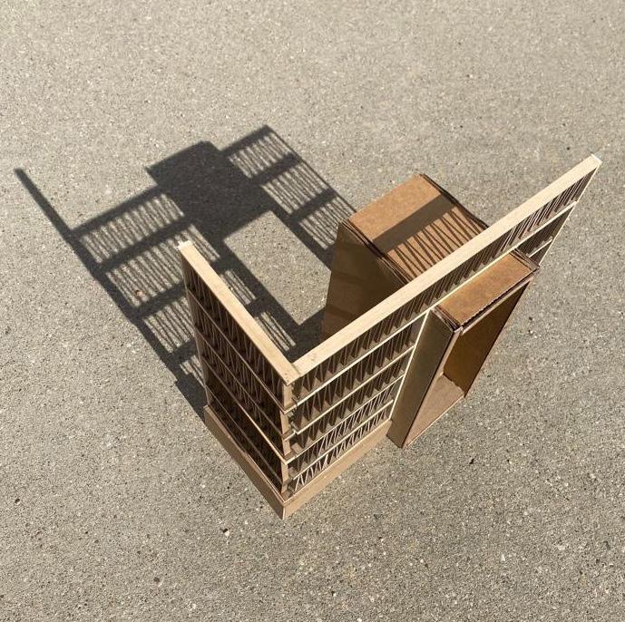
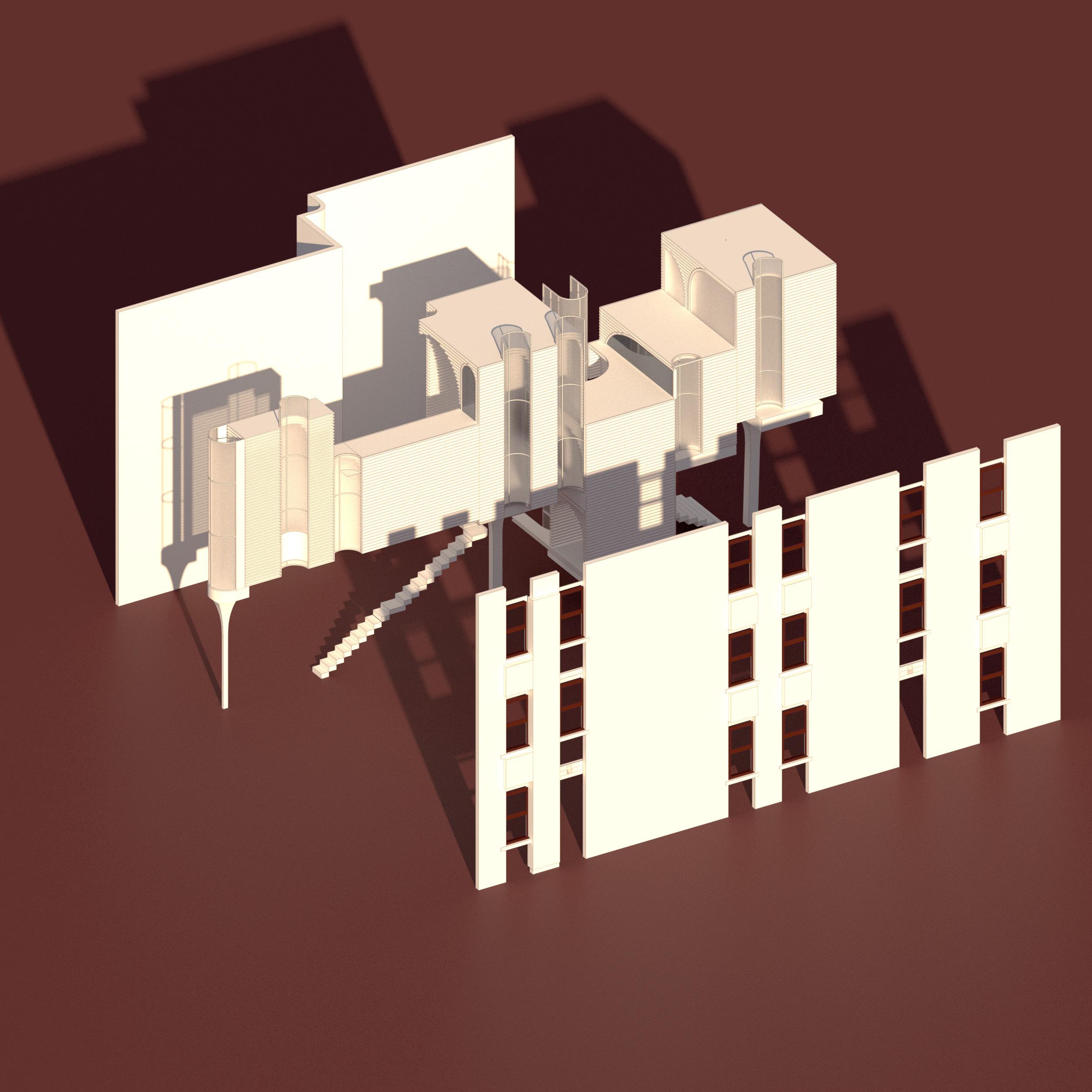
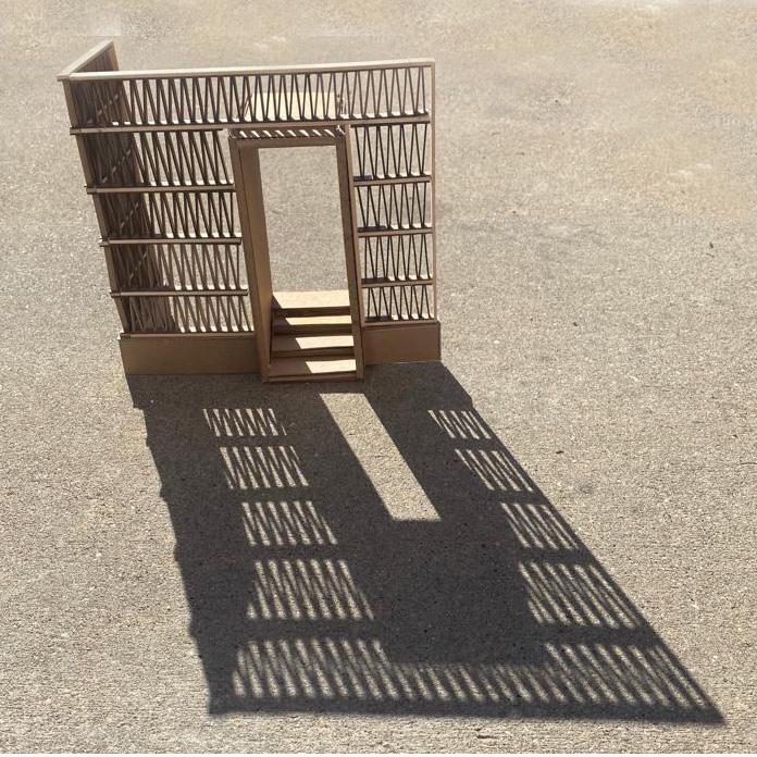
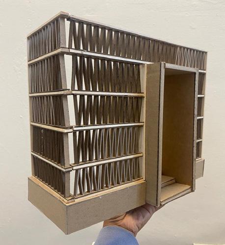
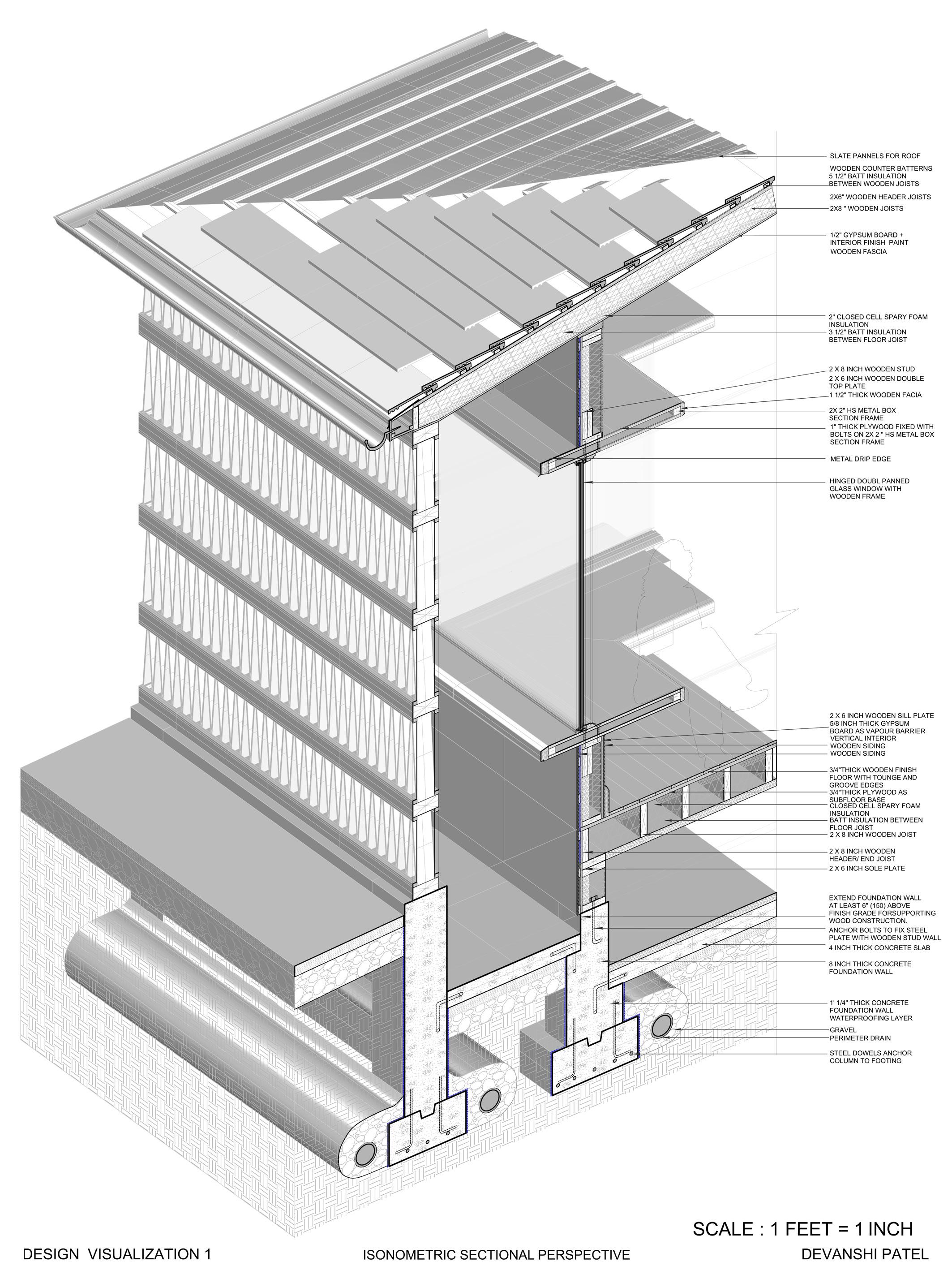
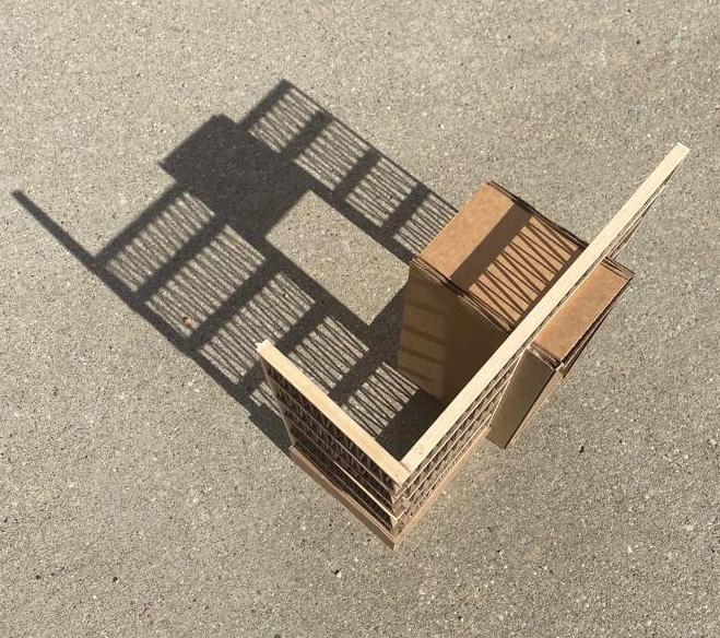
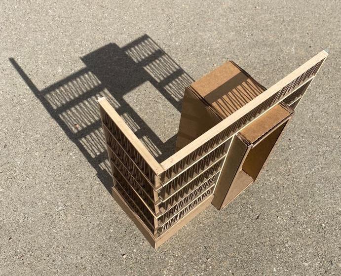
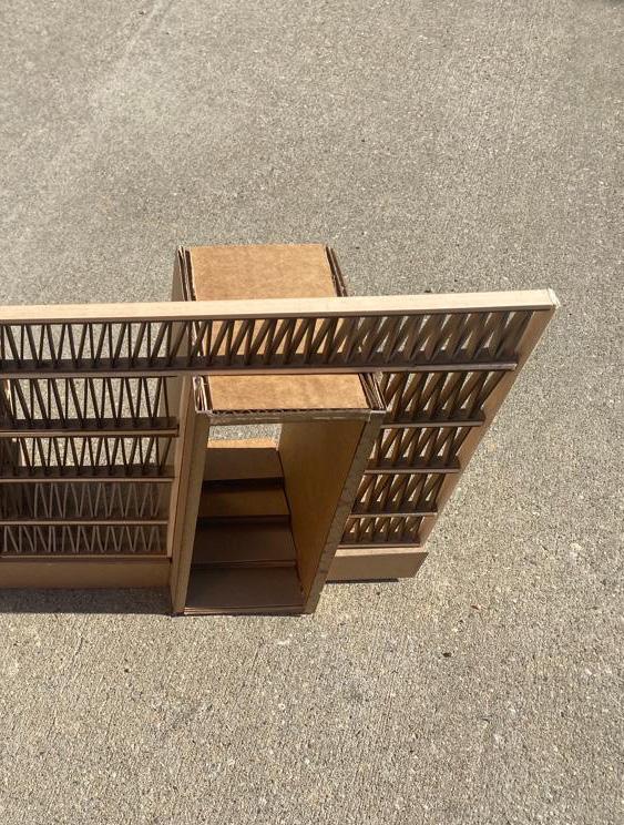
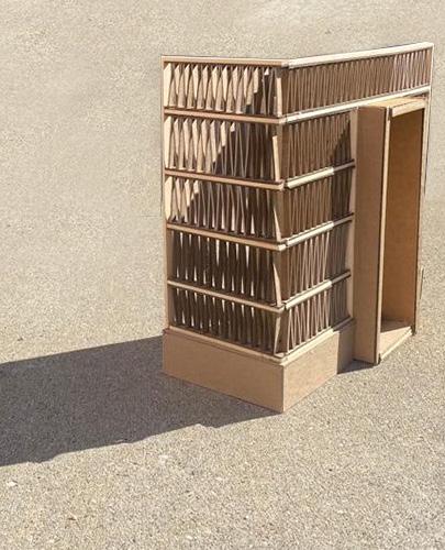
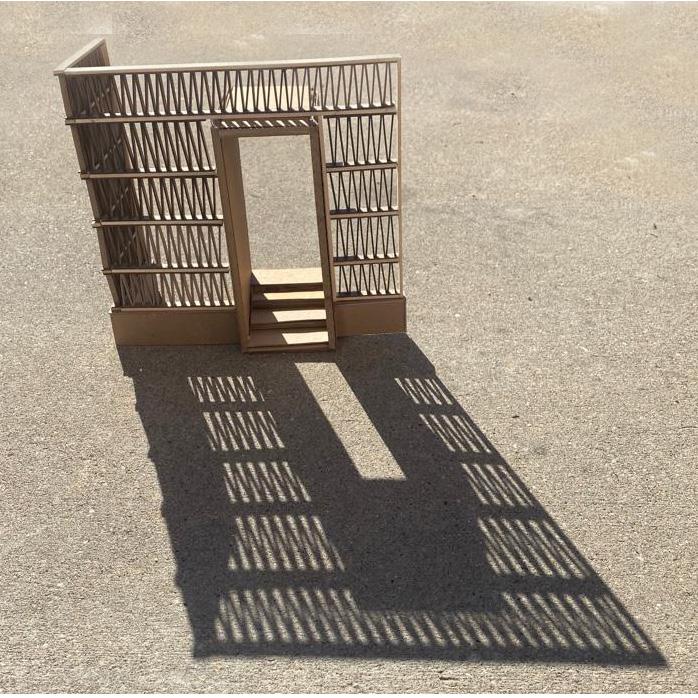
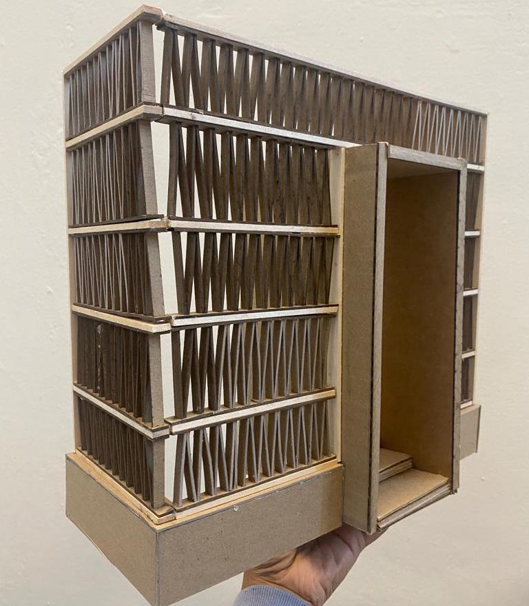
The project was about to create a detailed design for a single-story structure featuring a crawl space beneath, constructed primarily with wood. The structure has a sloped roof and include significant glazing, with 40% of the total glazing area on the south side and 25% on the east side. Additionally, the entry point is situated on the east side of the building.
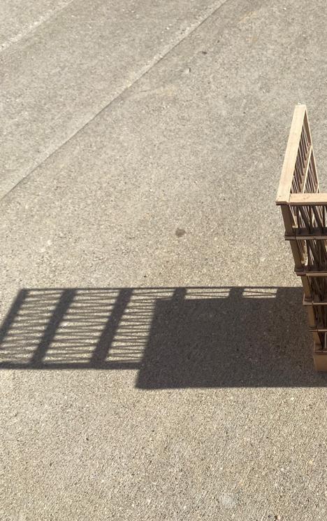
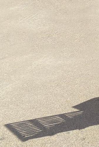
The facade design prioritizes privacy by limiting visibility from the interior to the exterior while restricting views from the exterior to the interior. To achieve this, a buffer space is incorporated between the facade and the interior glazing wall. This buffer space serves the dual purpose of preventing direct heat gain and minimizing wind exposure.
31 Facade Study

33 Facade Study Sectional Isonometric
34 Facade Study
35 Facade Study
36 Misbehaved Tectonics
Misbehaved Tectonics 04
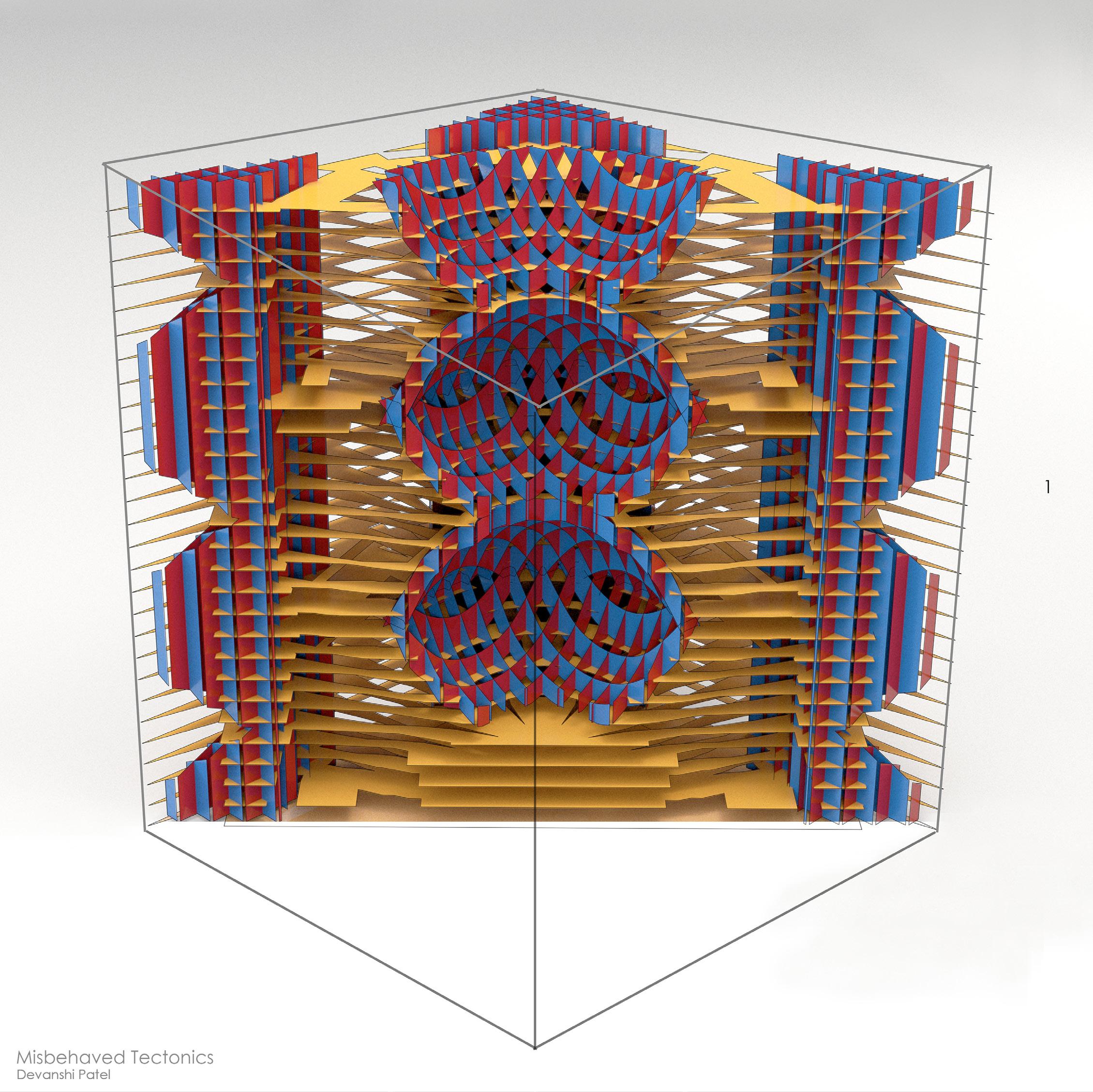
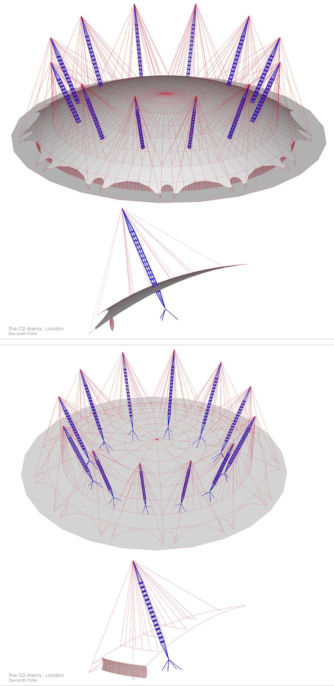
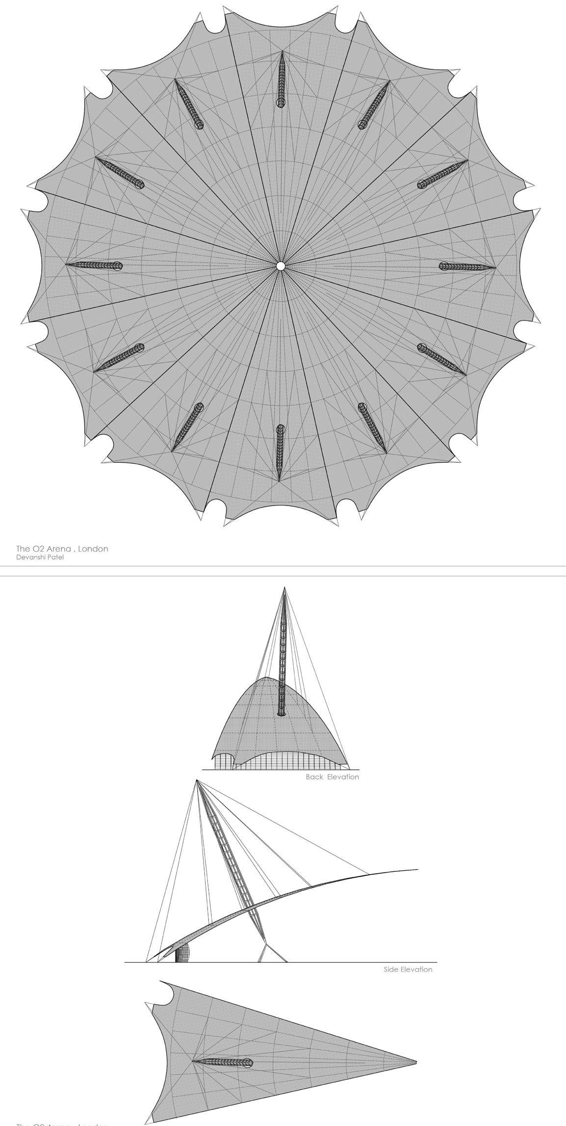
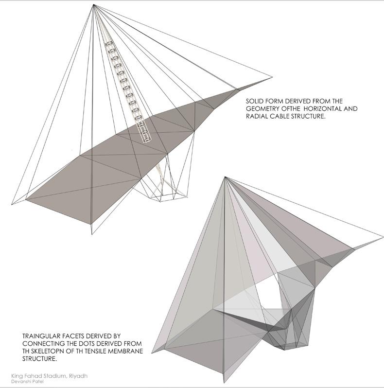
Academic Project (Spring 2024): Precedent study Radial cable tensile structure
Location: O2 Dome ,Londn, United Lingdom
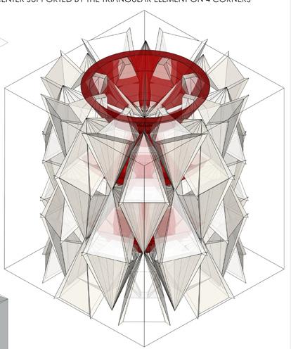
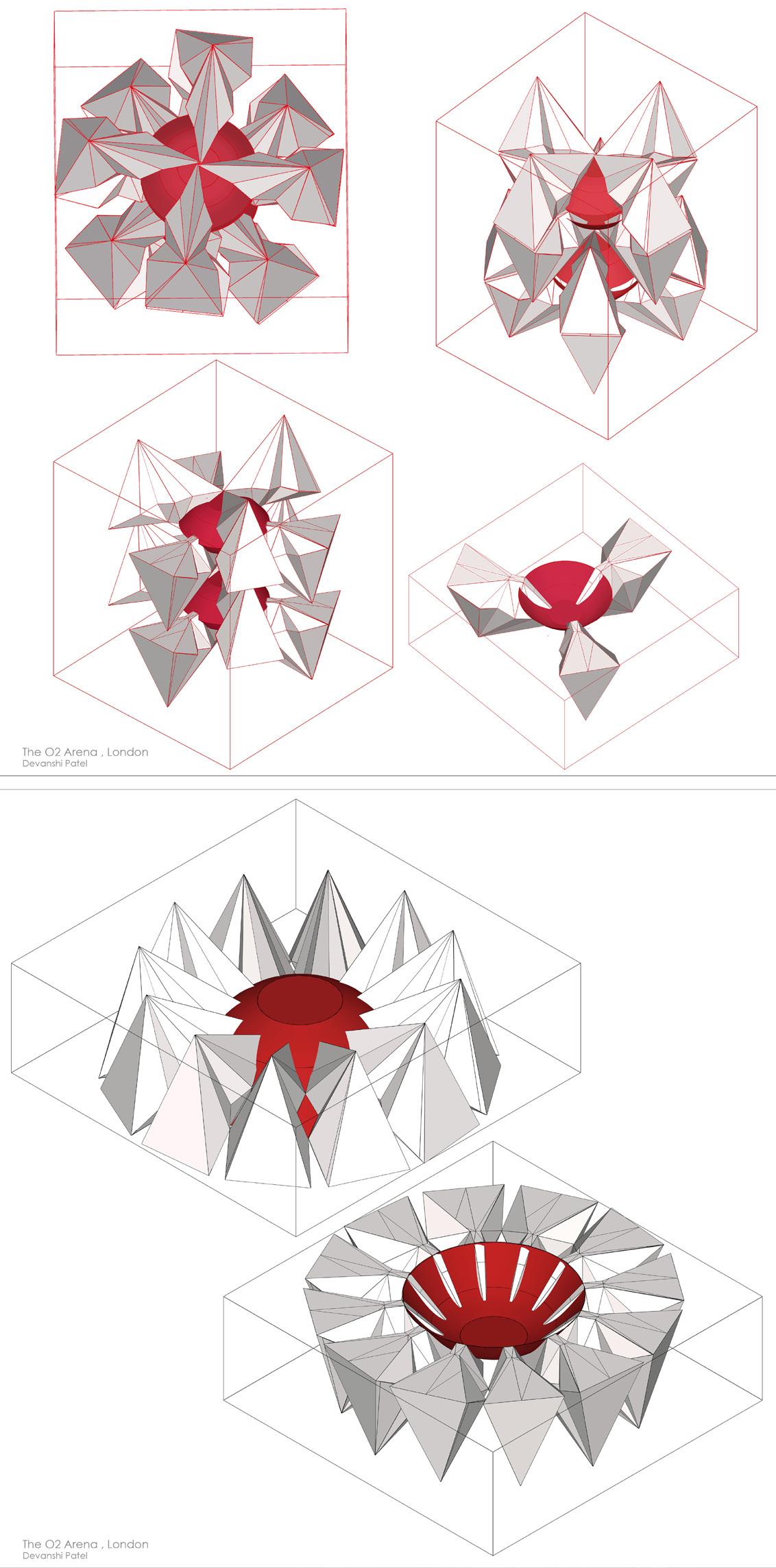
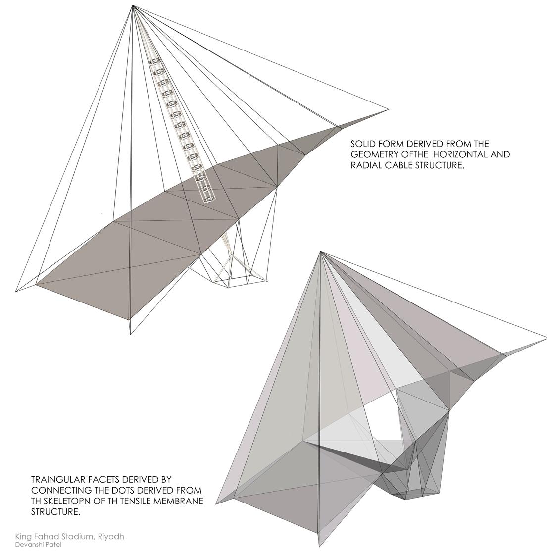
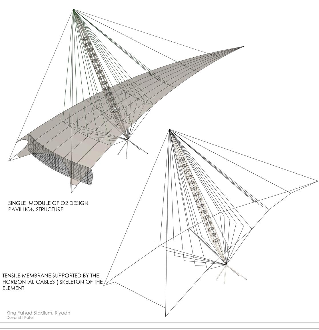
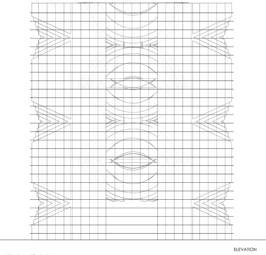
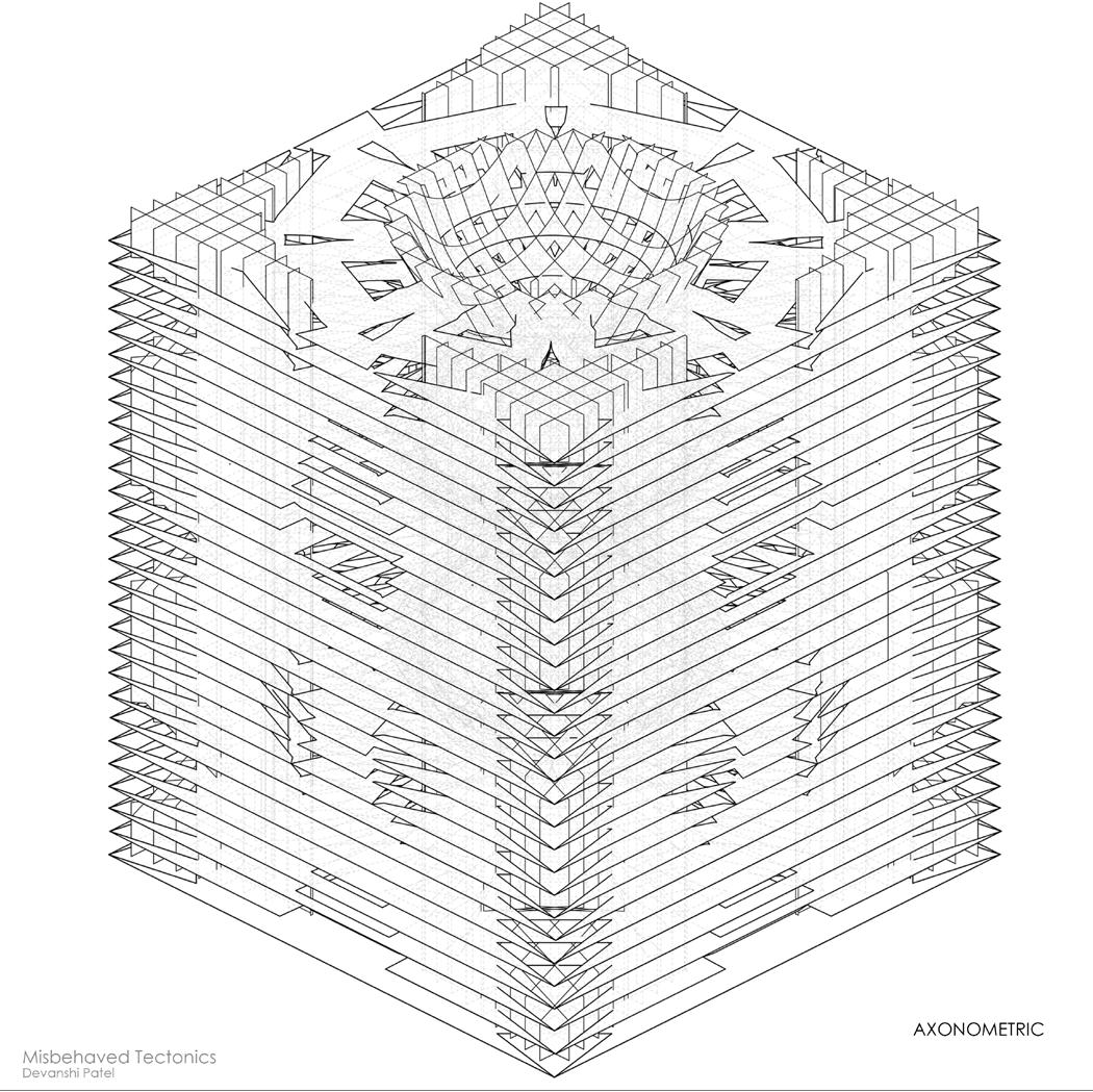
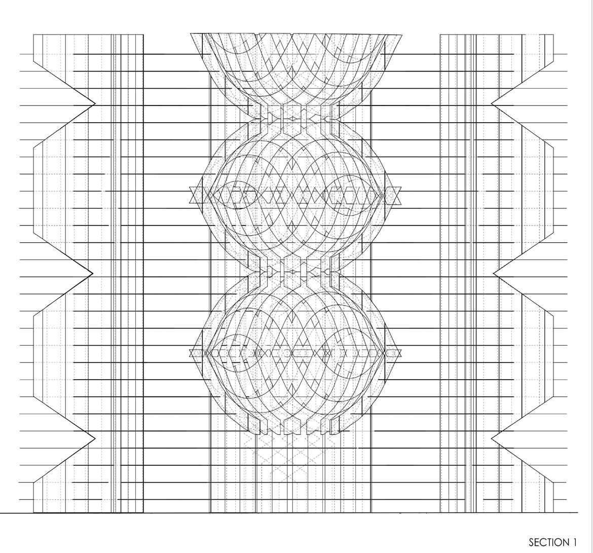
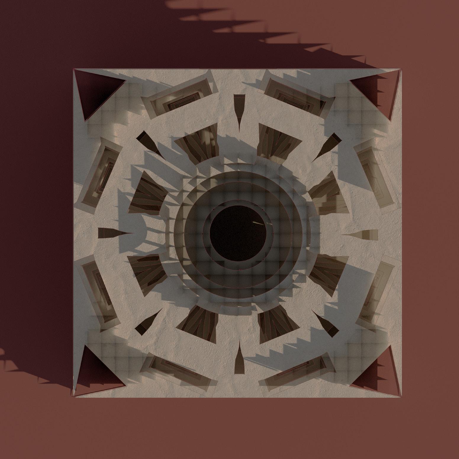
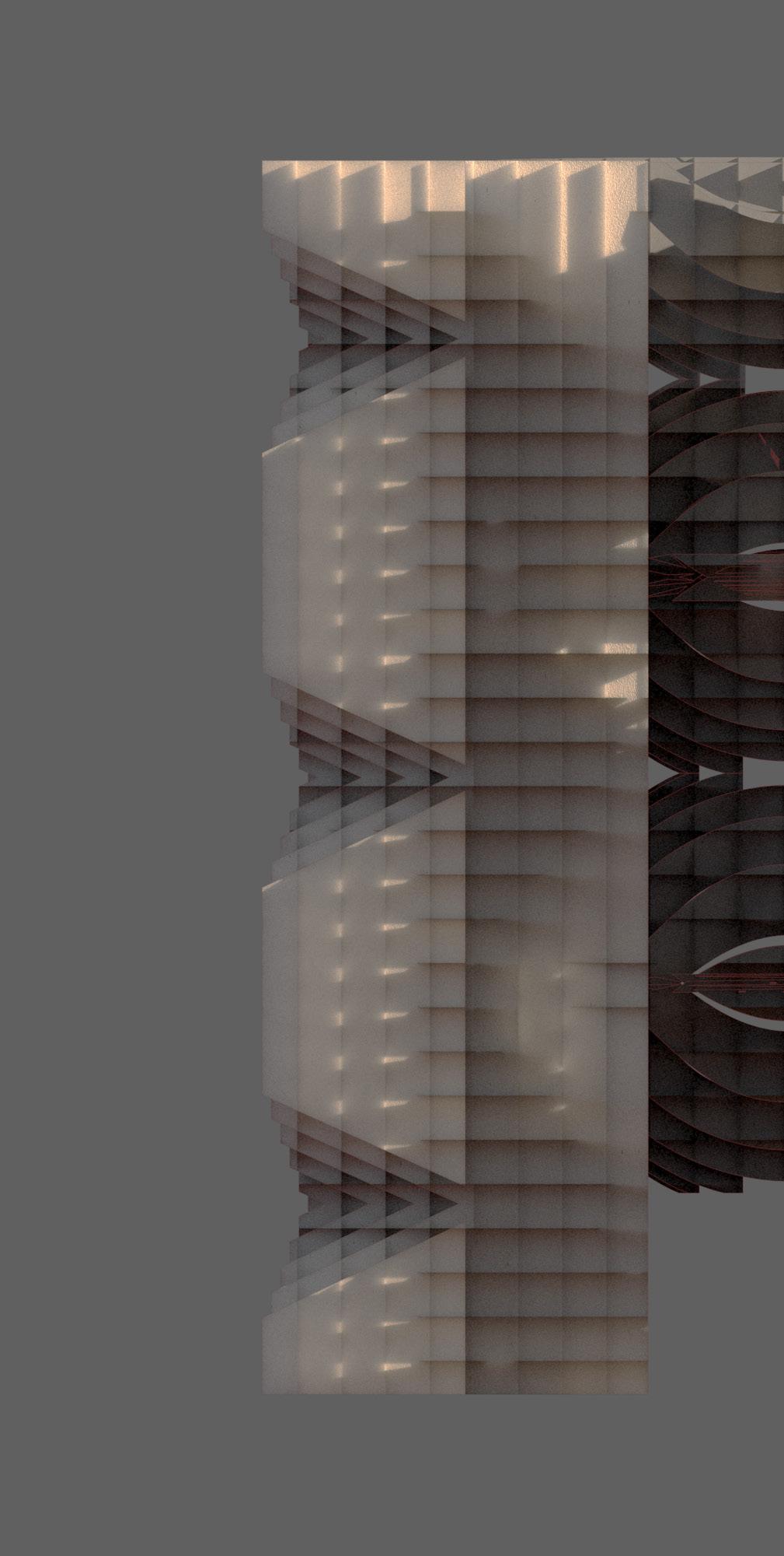
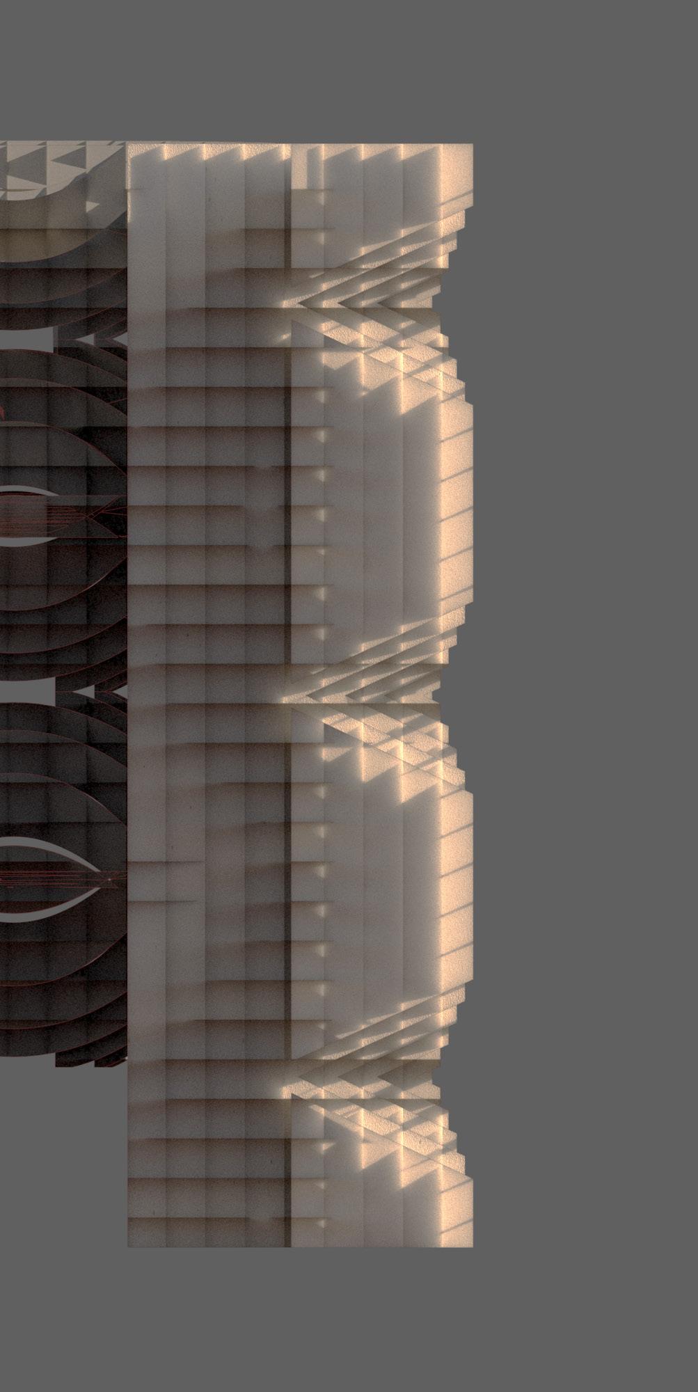
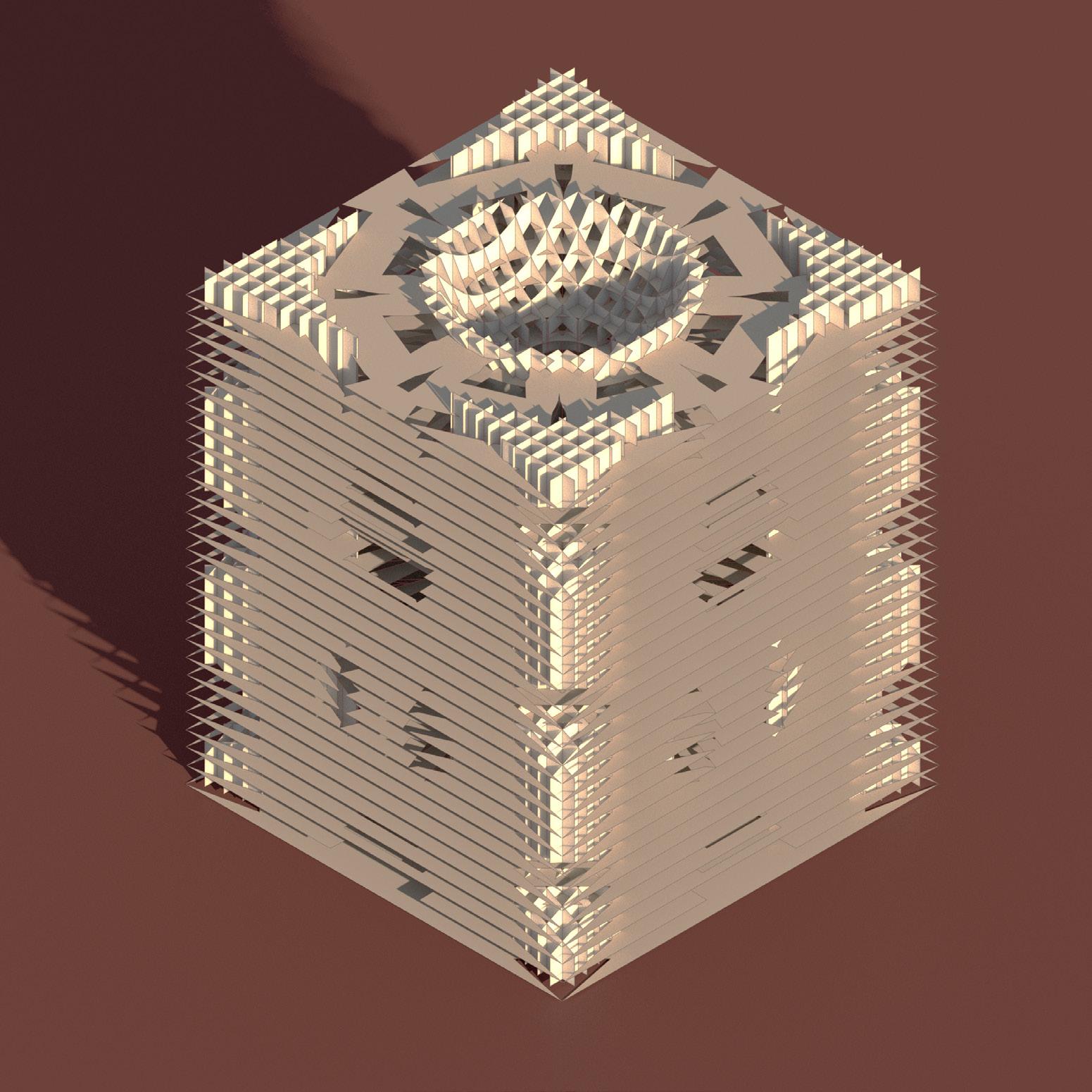
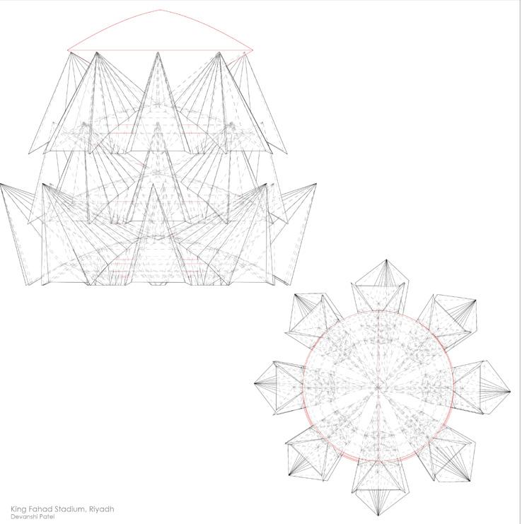
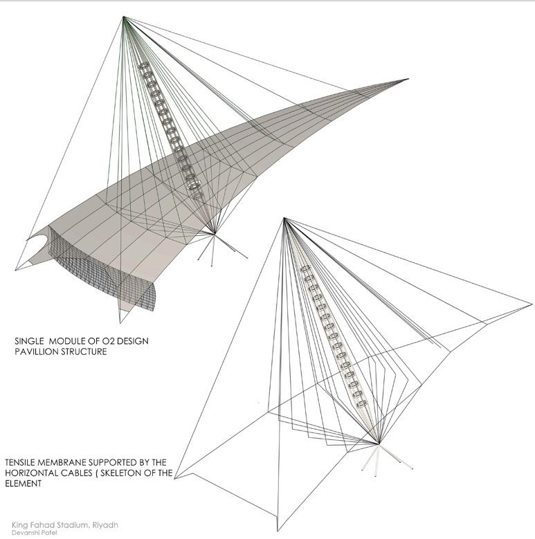
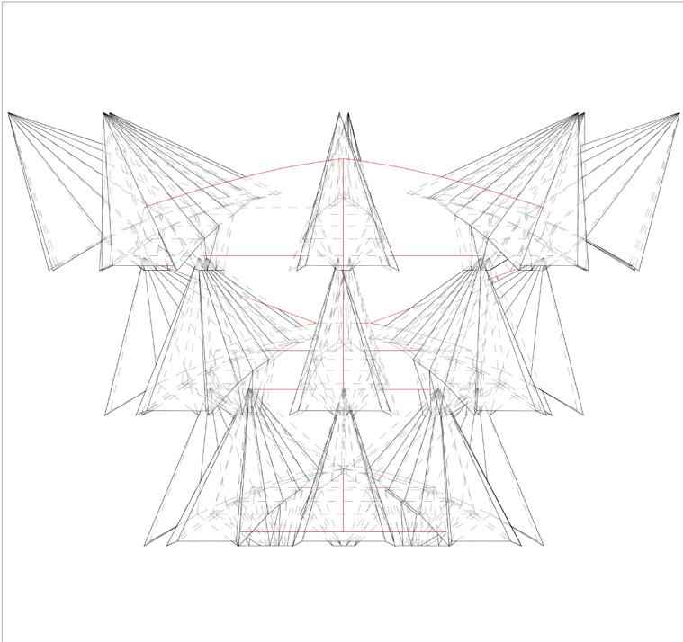
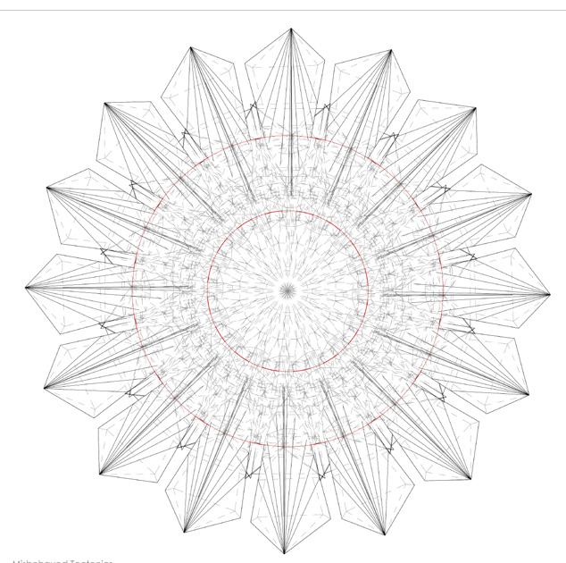
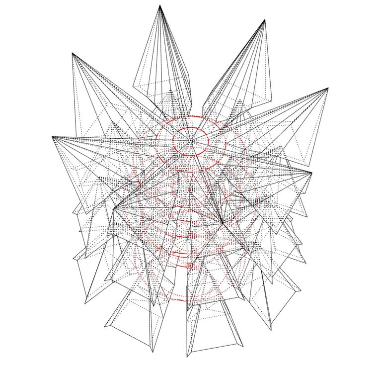
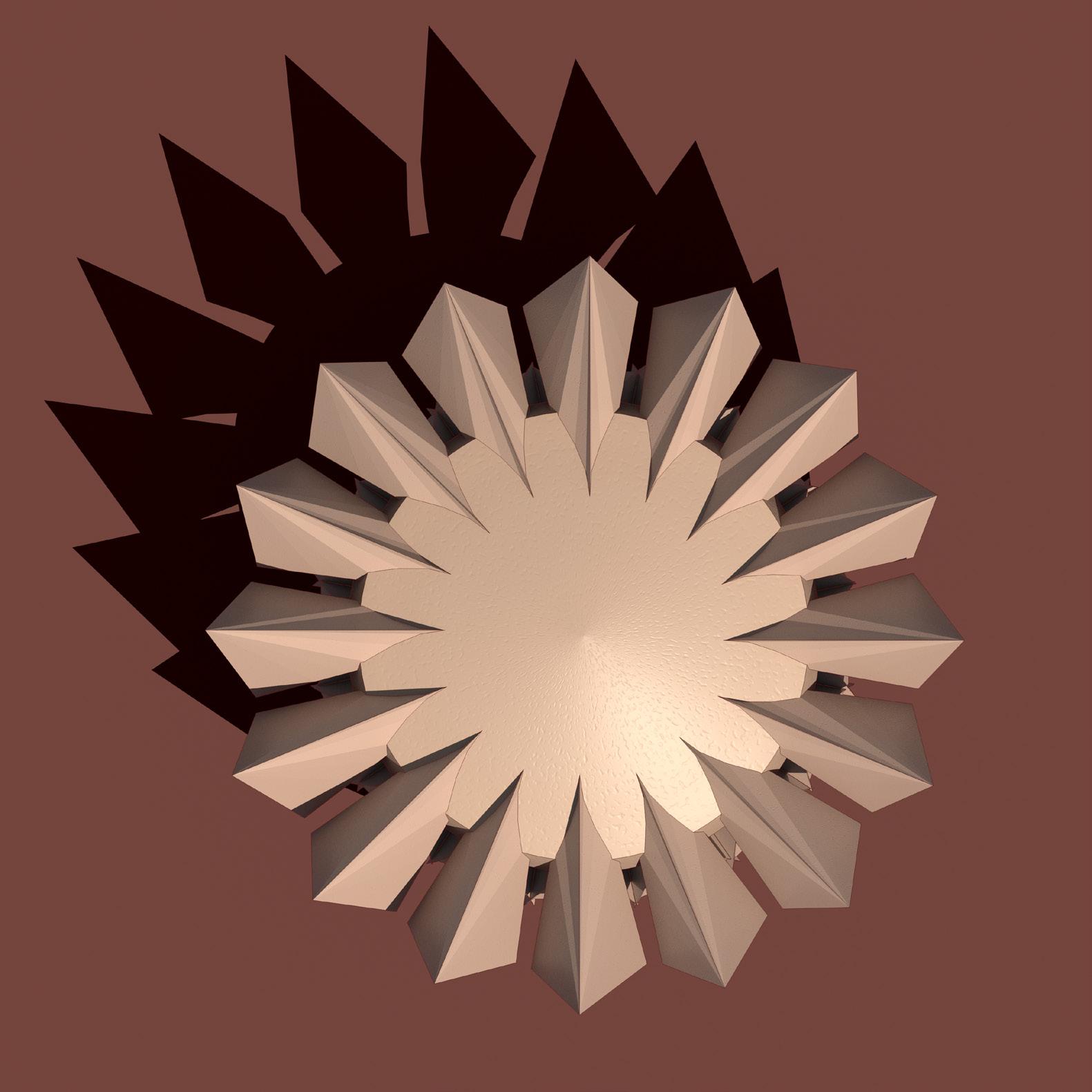
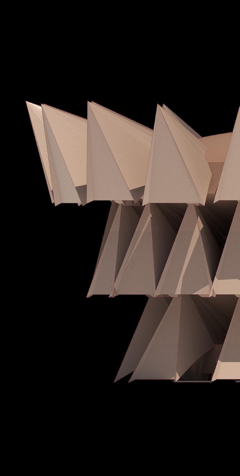
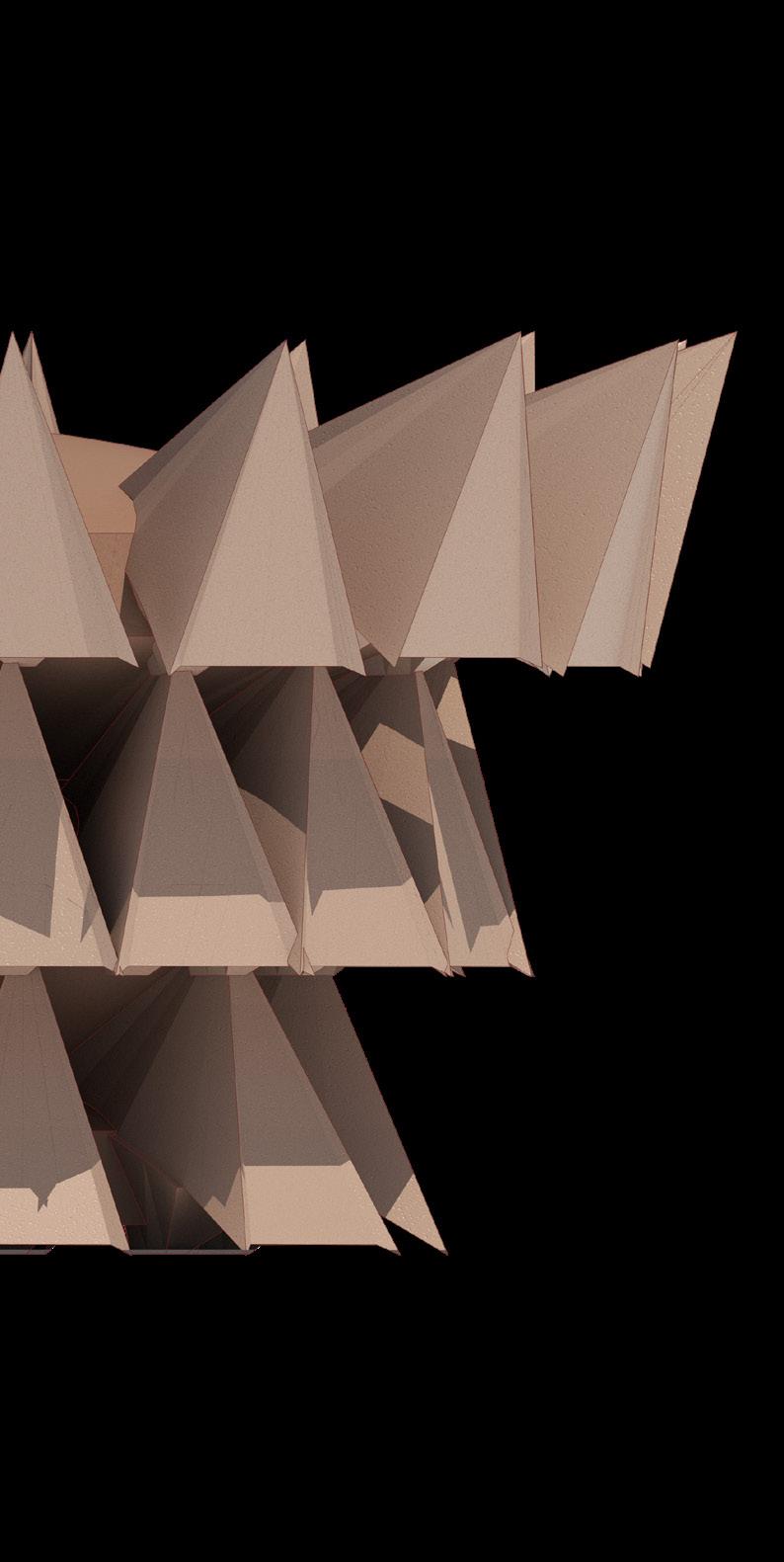
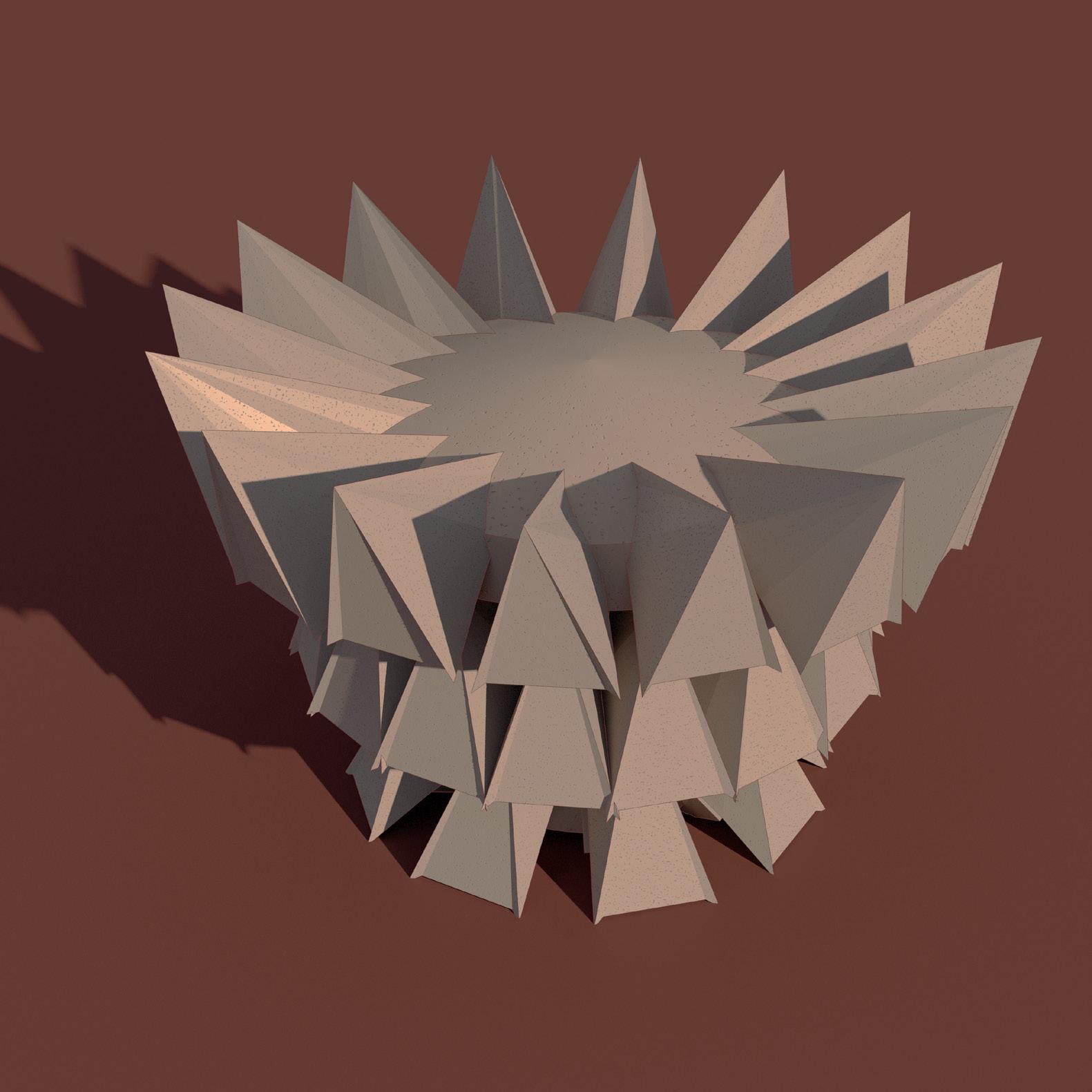
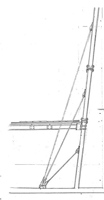
The project explored the influence of different construction methods on a radial cable tensile structure precedent. 3D objects were developed based on this study, utilizing laser cutting, 3D printing, and CNC milling to explore various geometries and parametrics. By intentionally misusing and appropriating each fabrication process, new structural hybrids emerged. This iterative process facilitated the creation of a catalog showcasing diverse tectonic possibilities and their associated fabrication materials.
Considdering precend t study various iterations were tried to potray the nature of tensile cables and the fabric which is shaped with the geometry of the radially arranged tensile cables.The relation between soild and void volumes, supported and suspended solids etc were explored throup three processes.
37 Misbehaved Tectonics
38 Misbehaved Tectonics
Precedent Study, O2 Dome, London
O2 Dome,London_ Tensile Cable skeleton
O2 Dome, London_ Plan
O2 Dome, London_ Module
O2
O2
Misbehaved Tectonics
O2 Dome, London_Mirror and rotated modules
Dome, London_Solid vs Void
O2 Dome, London_Solid vs Void
Dome, London_Tensile Cable Skeleton
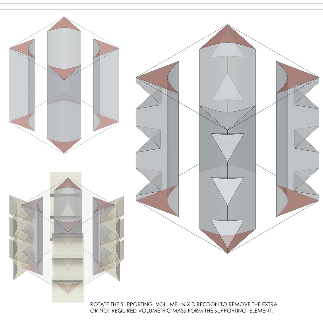
Supported Volumes
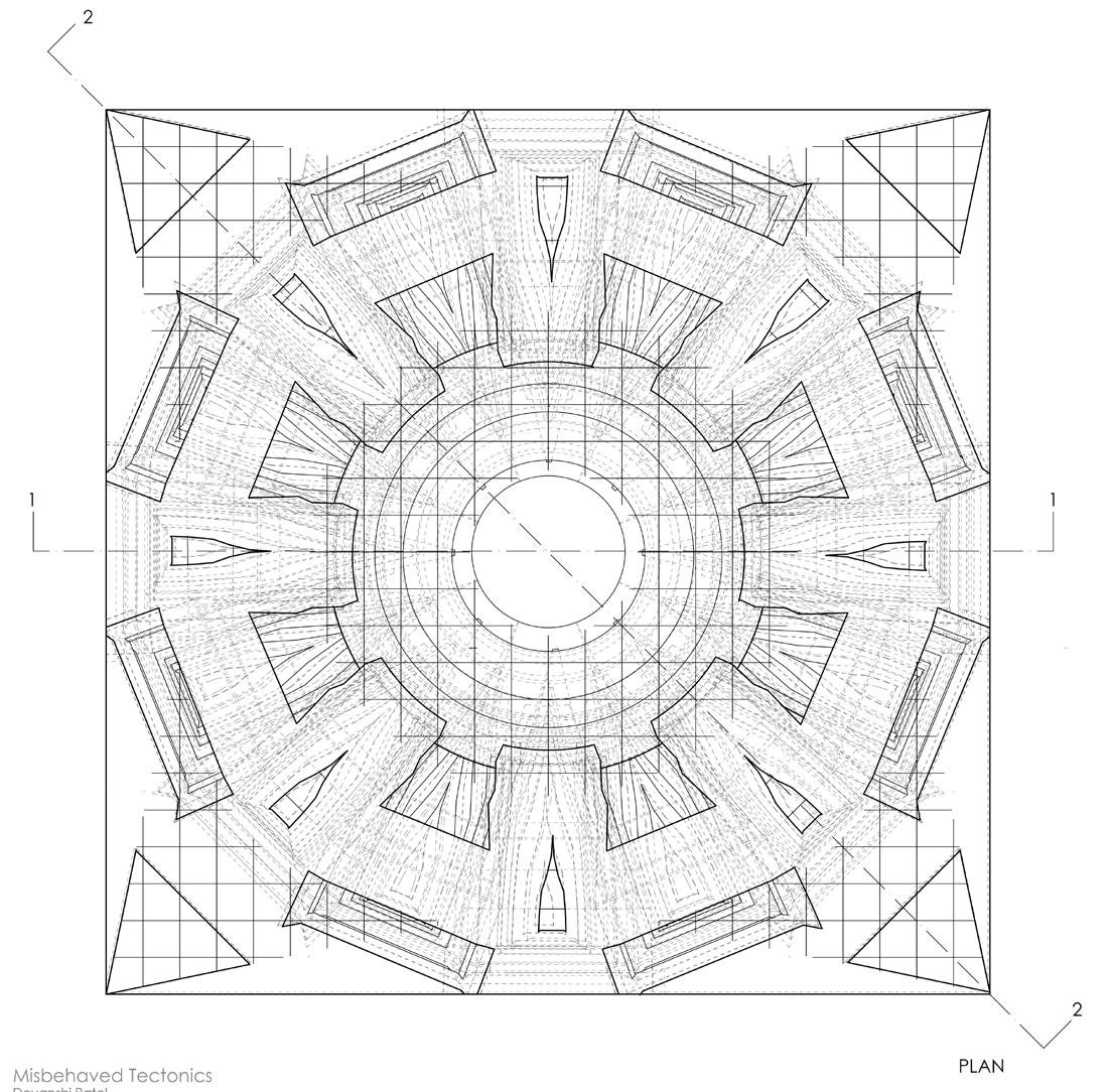
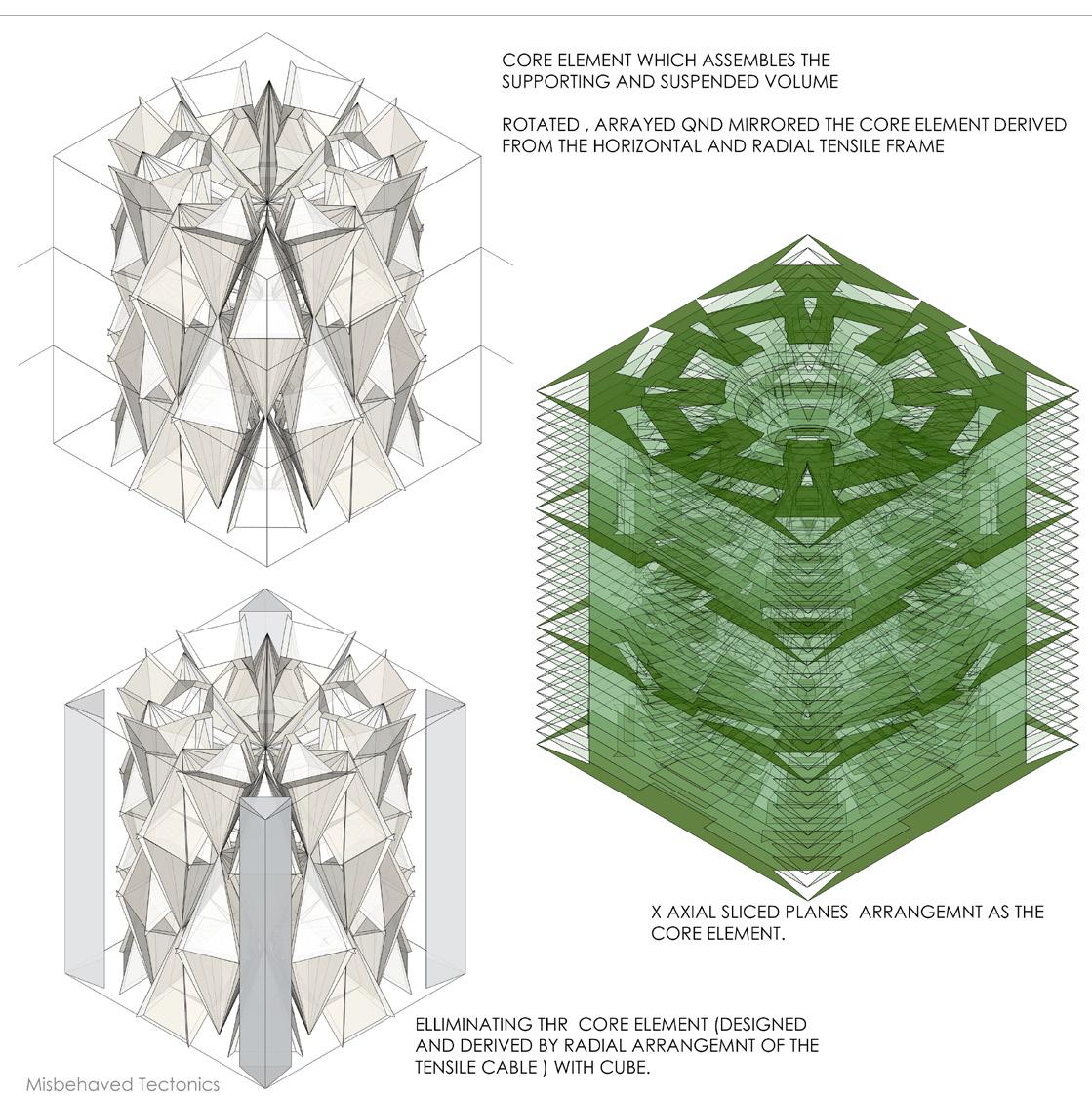
Core volume to bind support and suspended solid
40 Misbehaved Tectonics
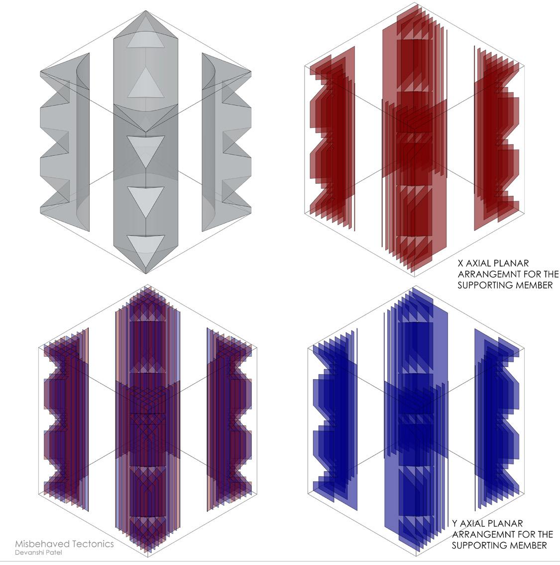
Supported volumes
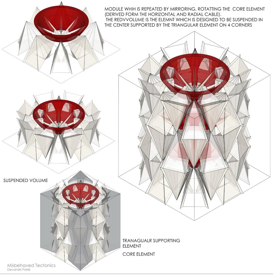
Supports, suspended volume and core
41 Misbehaved Tectonics
42 Misbehaved Tectonics
43 Misbehaved Tectonics
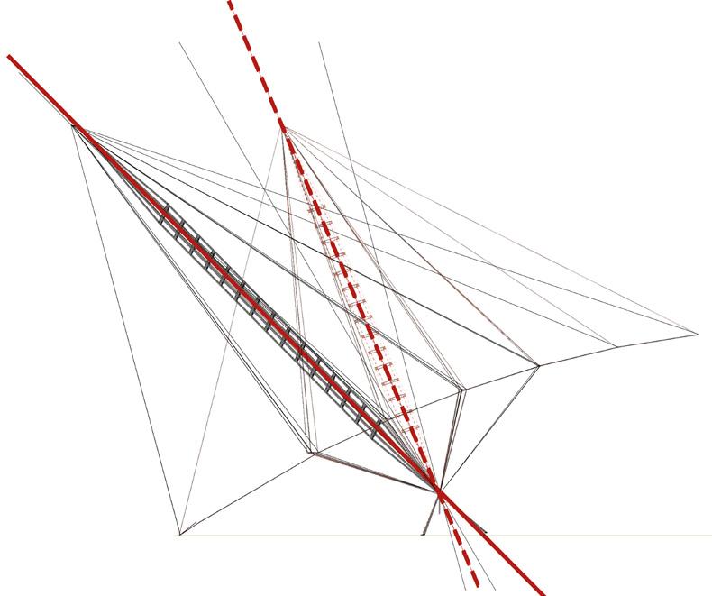
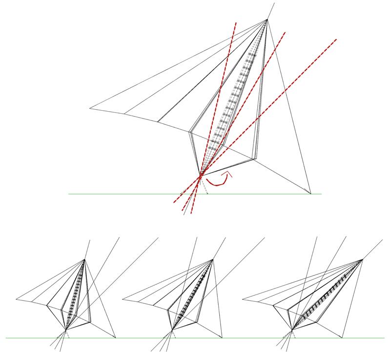
Supported stem rotated 22.5 degree
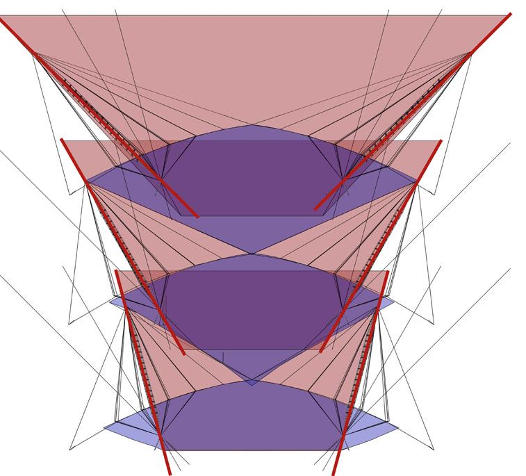
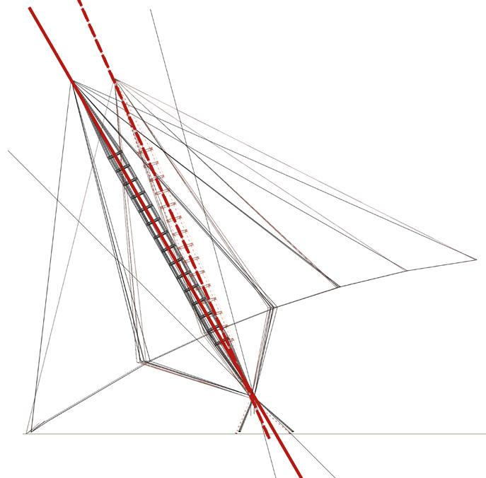
Supported stem rotated 15 degree
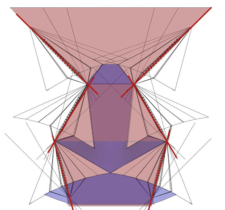

Supported stem rotated -15 degree
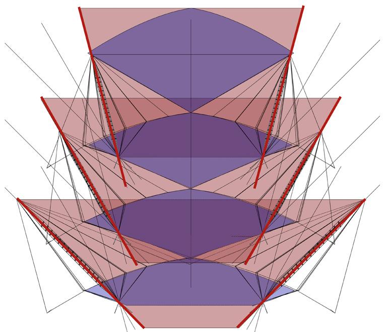
Void and Solid forms achieved by rotating the core stem to 3 different angles
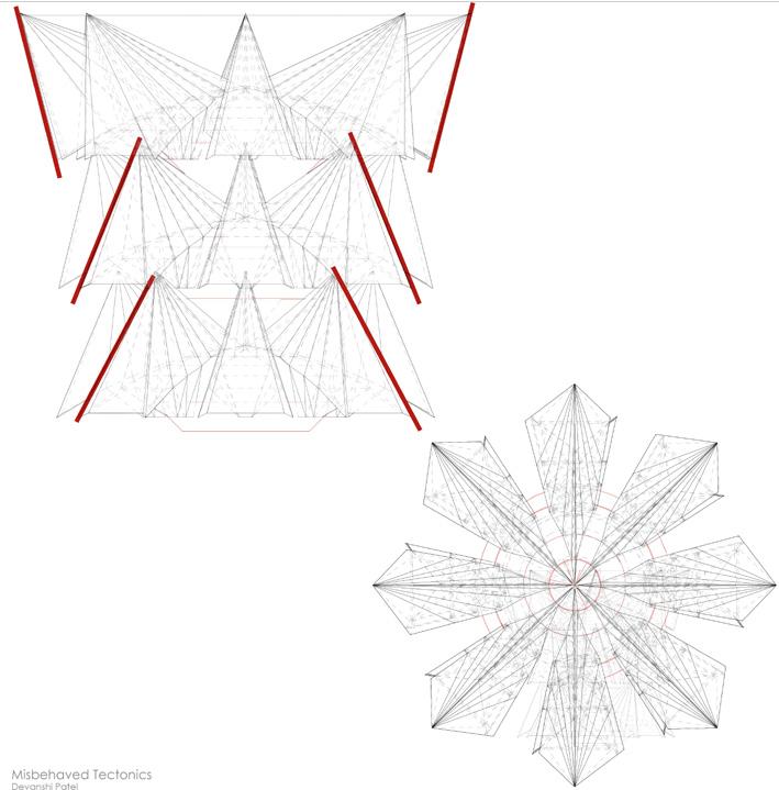
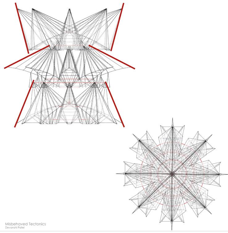
Iterations of 3d volumes achieved by playing with angularity by rotating the stem
44 Misbehaved Tectonics
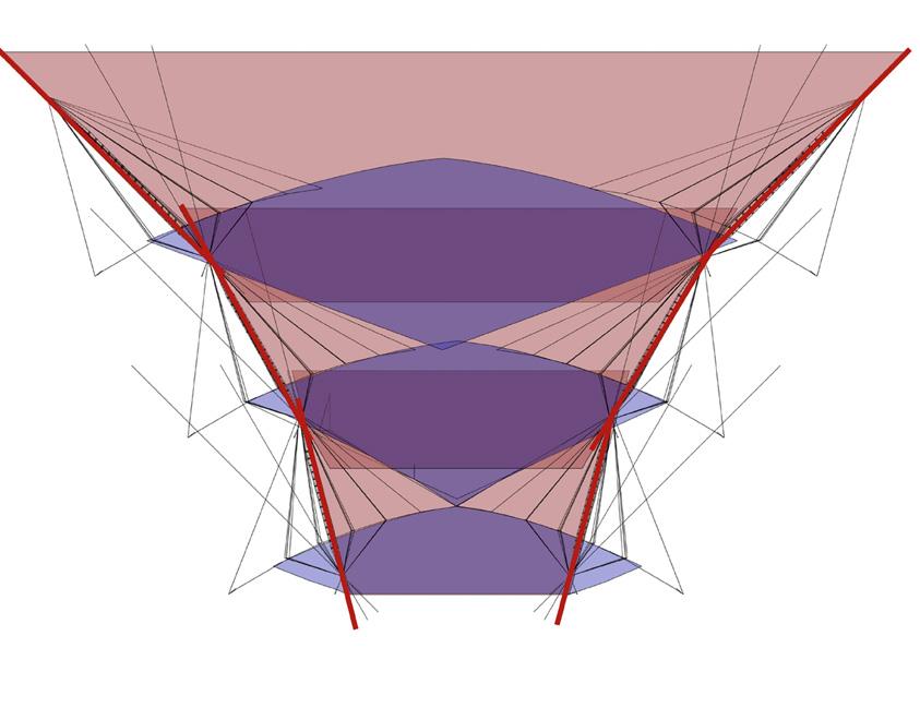
3d volume exploring the most tilted module on the top to least tilted at bottom
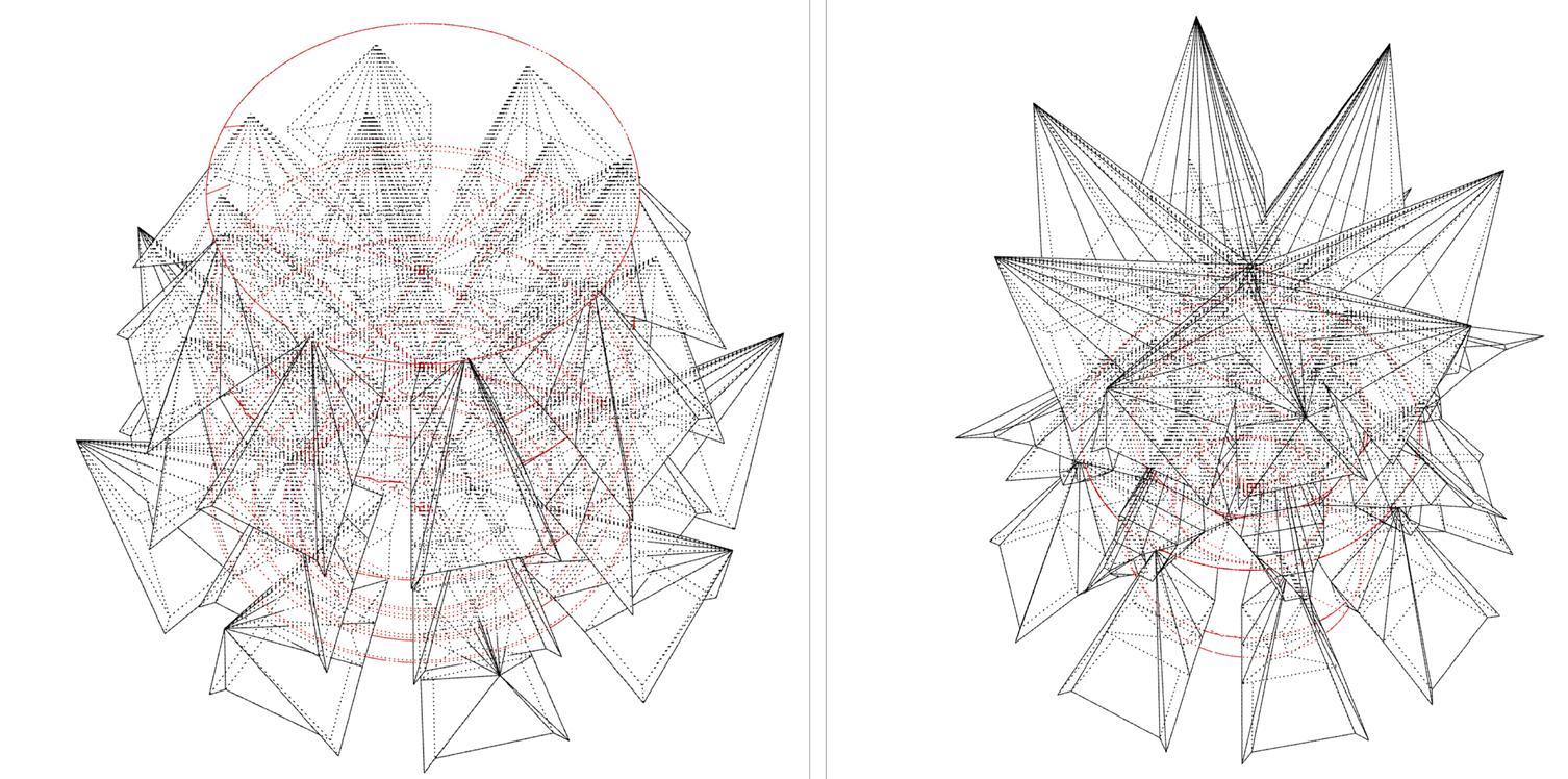
Iterations of 3d volumes achieved by playing with angularity by rotating the stem
45 Misbehaved Tectonics
Elevation Plan
46 Misbehaved Tectonics
47 Misbehaved Tectonics
48 Tectonics in Architecture

05
Tectonics in Architecture
Academic Project (Fall 2023): Precedent study for Thin House
Location: Neue National Gallery, Berlin, Germany
Area: 53820 sq feet
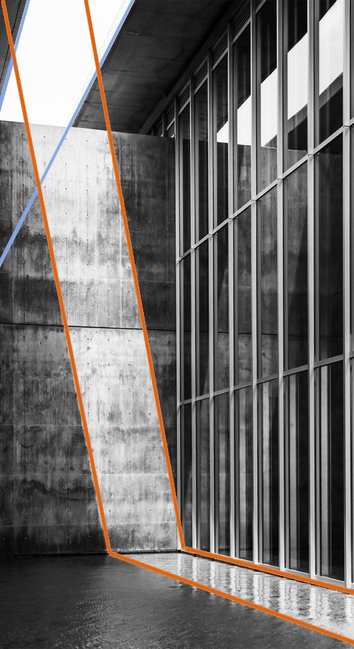
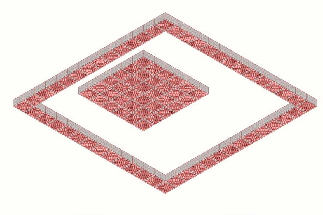
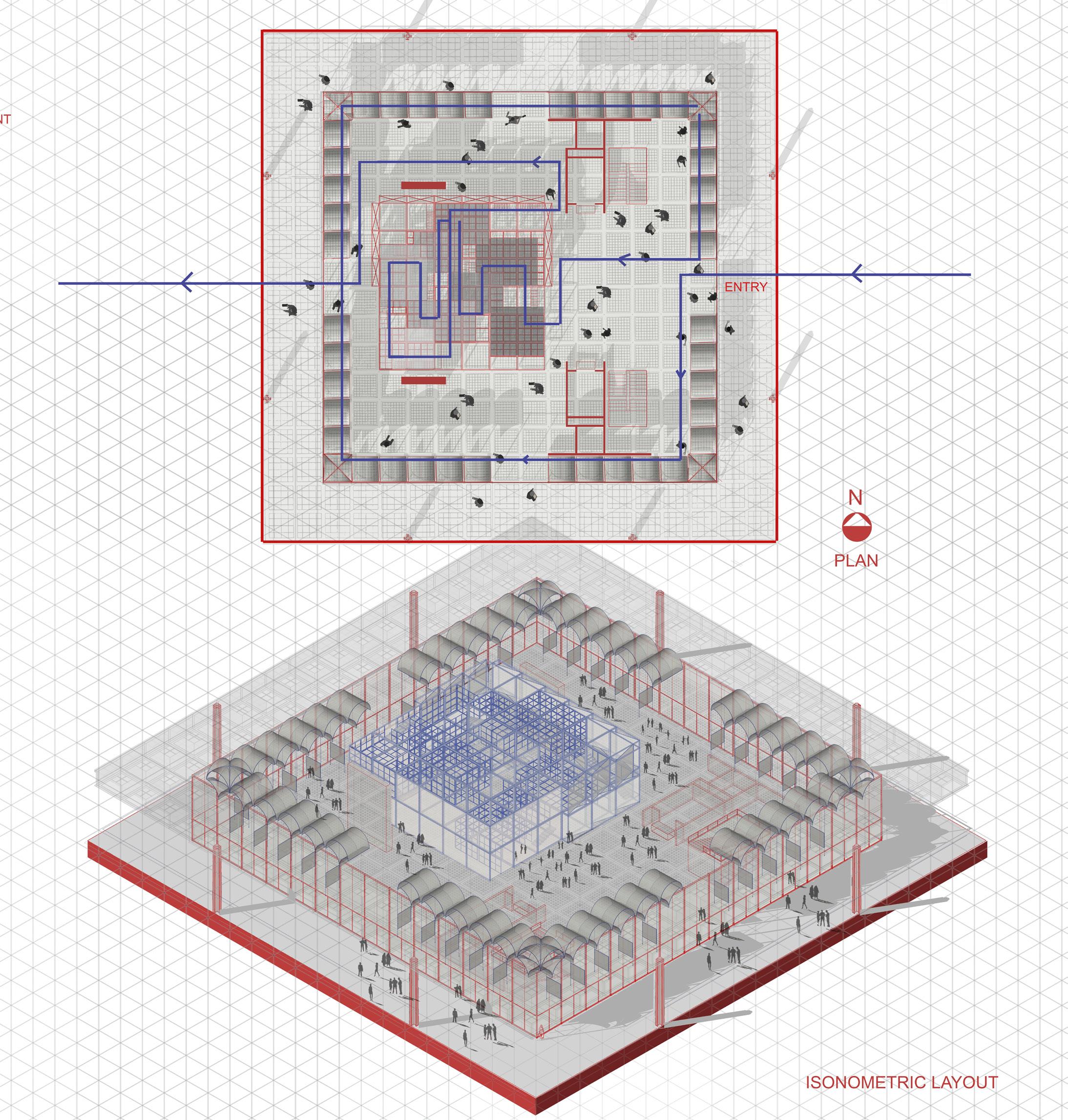
This project is based on a precedent study of the works of Moshe Safdie and Tadao Ando. Several buildings by these architects were analyzed to inform the design of the exhibition space within the Neue National Gallery, originally designed by Mies van der Rohe.
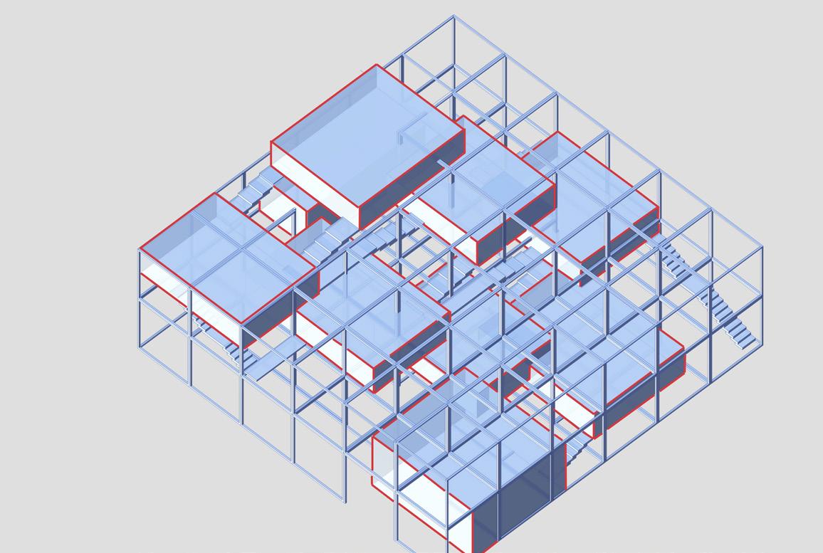
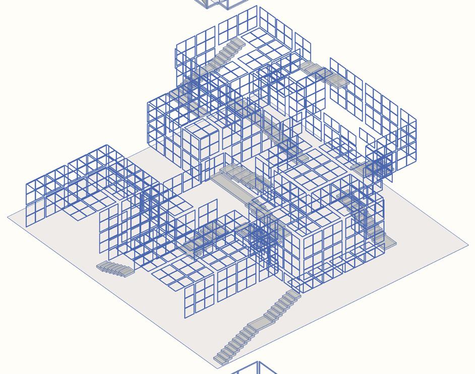
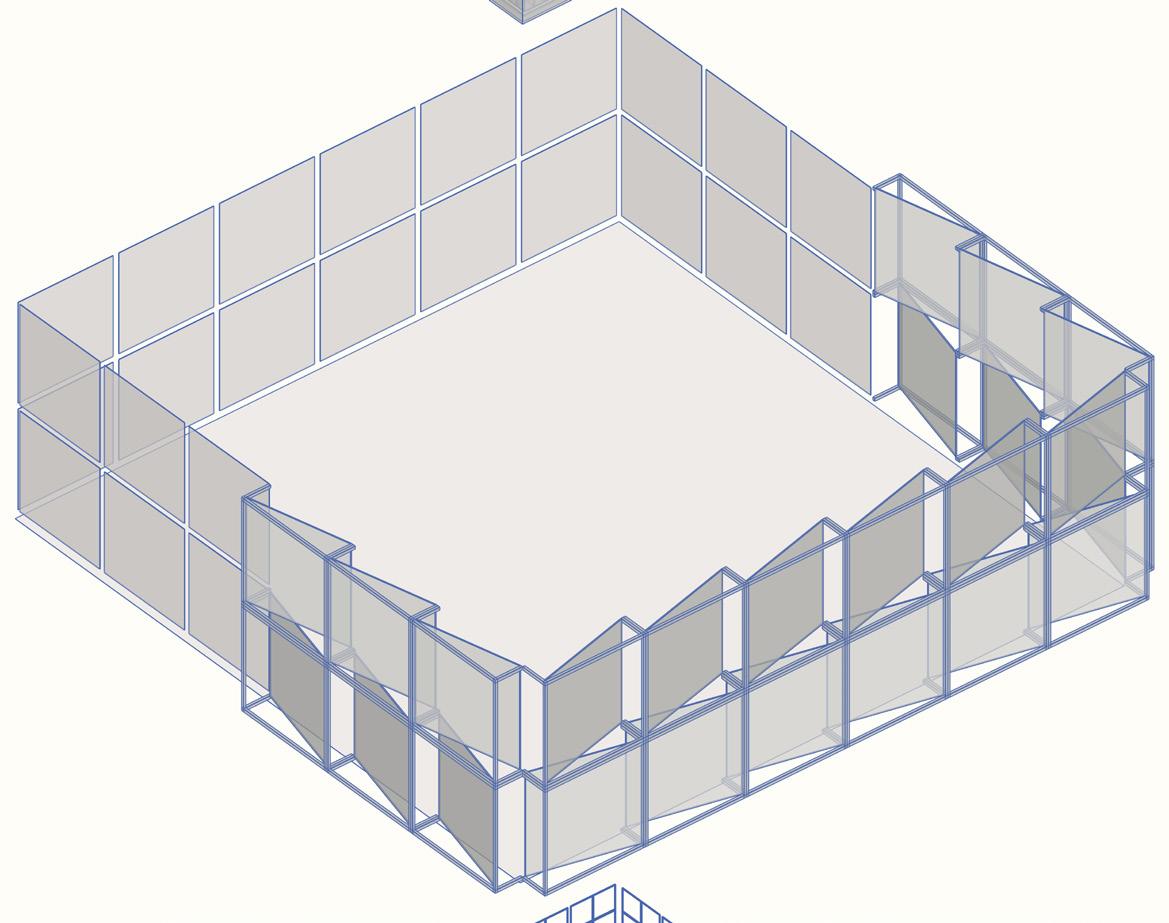
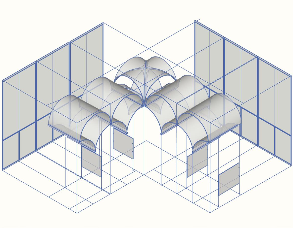
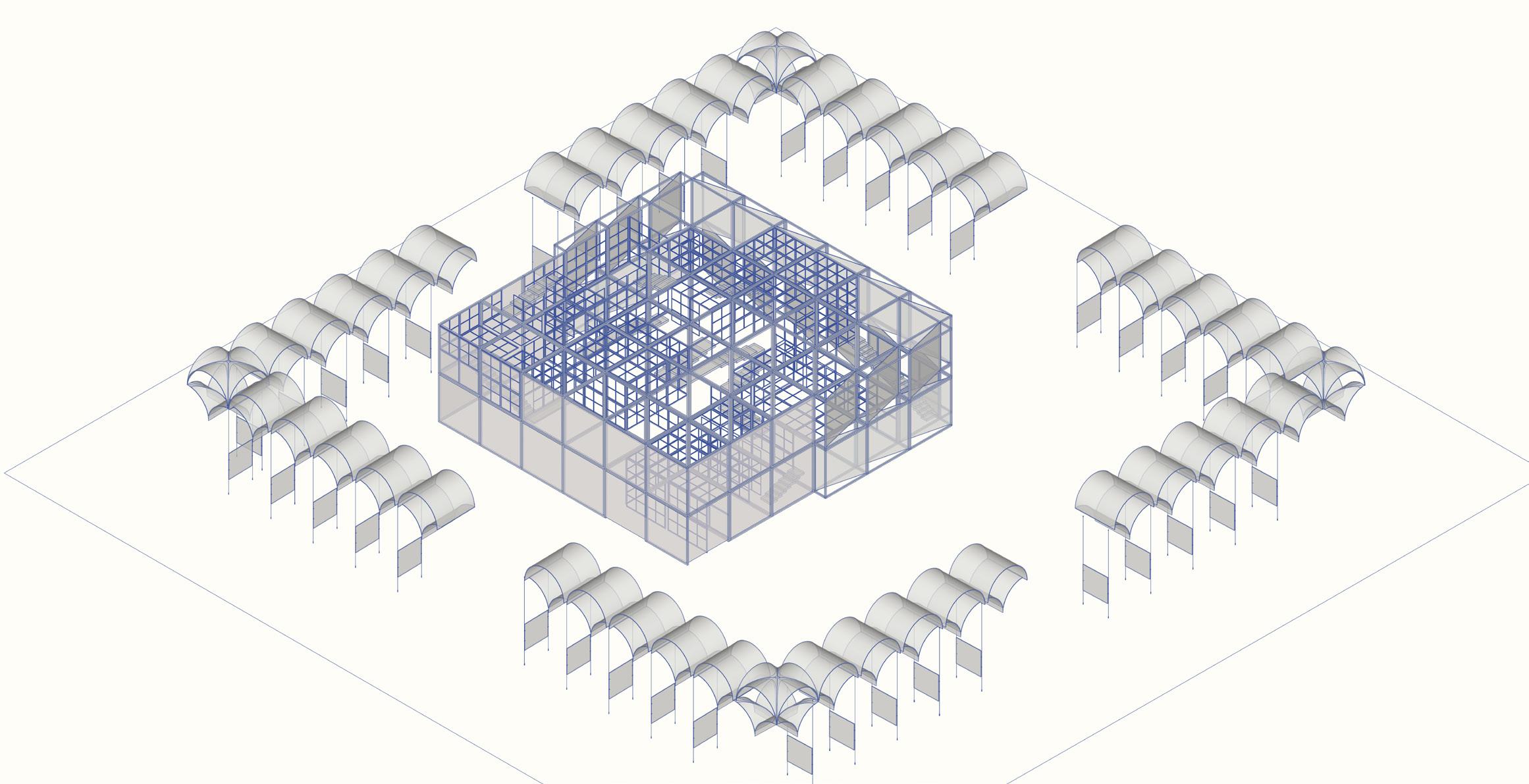
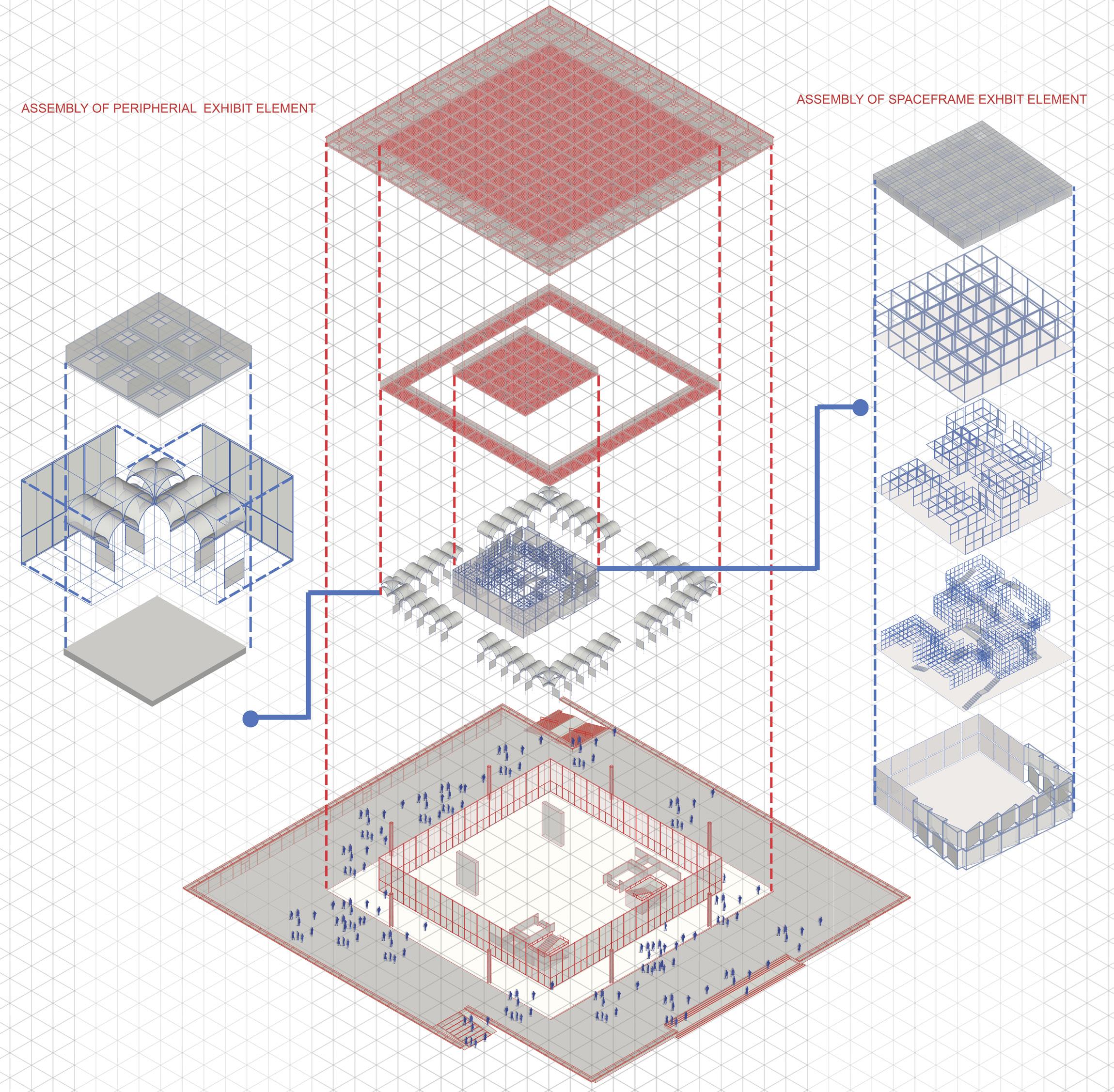
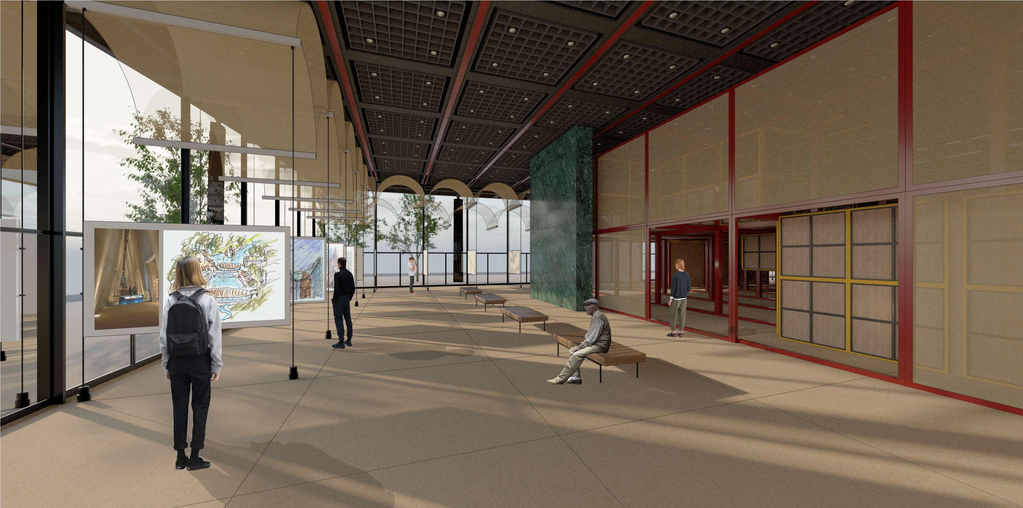
The temporary interior exhibition structure within the building was designed by integrating the geometry of the building itself. Inspired by the solid and void forms of the arches found in many of Moshe Safdie’s buildings, these elements were strategically positioned around the periphery, serving as supports for suspended exhibition panels. The central interior structure features a grid of cubes with staggered levels, following the same geometry and proportions as those found in the works of both architects, Safdie and Ando. This space thus serves as a convergence between the modern and contemporary architectural styles of Moshe Safdie and Tadao Ando, showcasing their works within the iconic building designed by Mies van der Rohe.
Orchestration of lights are considered the major concept where light elements made of fabric an faceted planks are designed considering the architetcural style of both architects.
49 Tectonics in Architecture
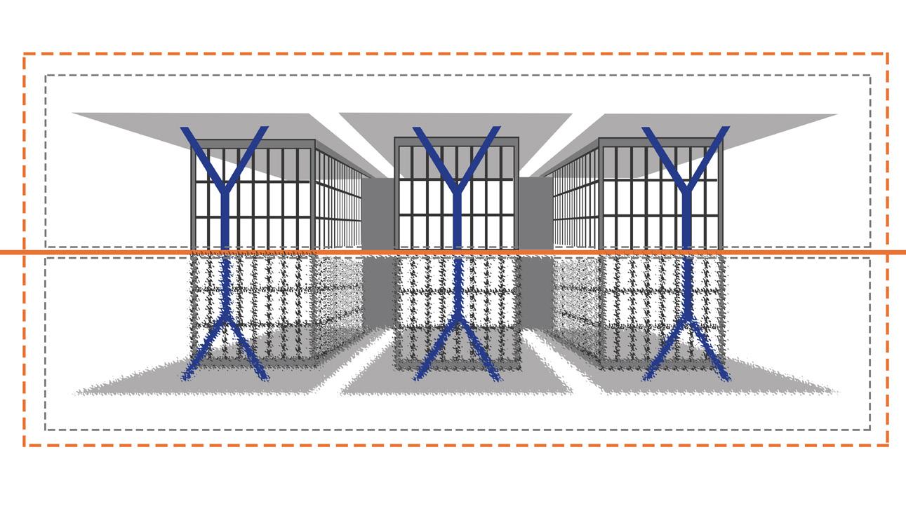
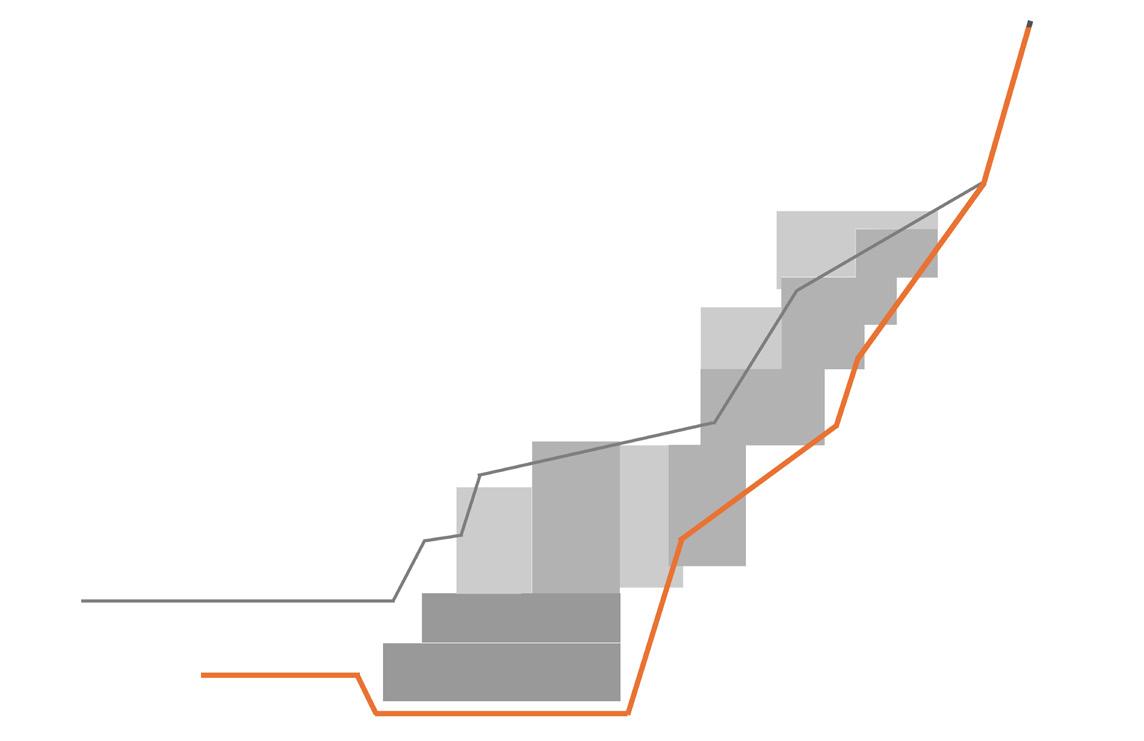
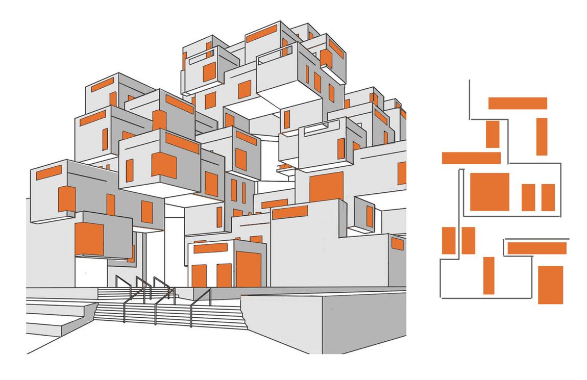
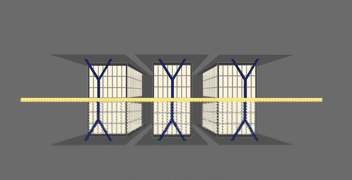
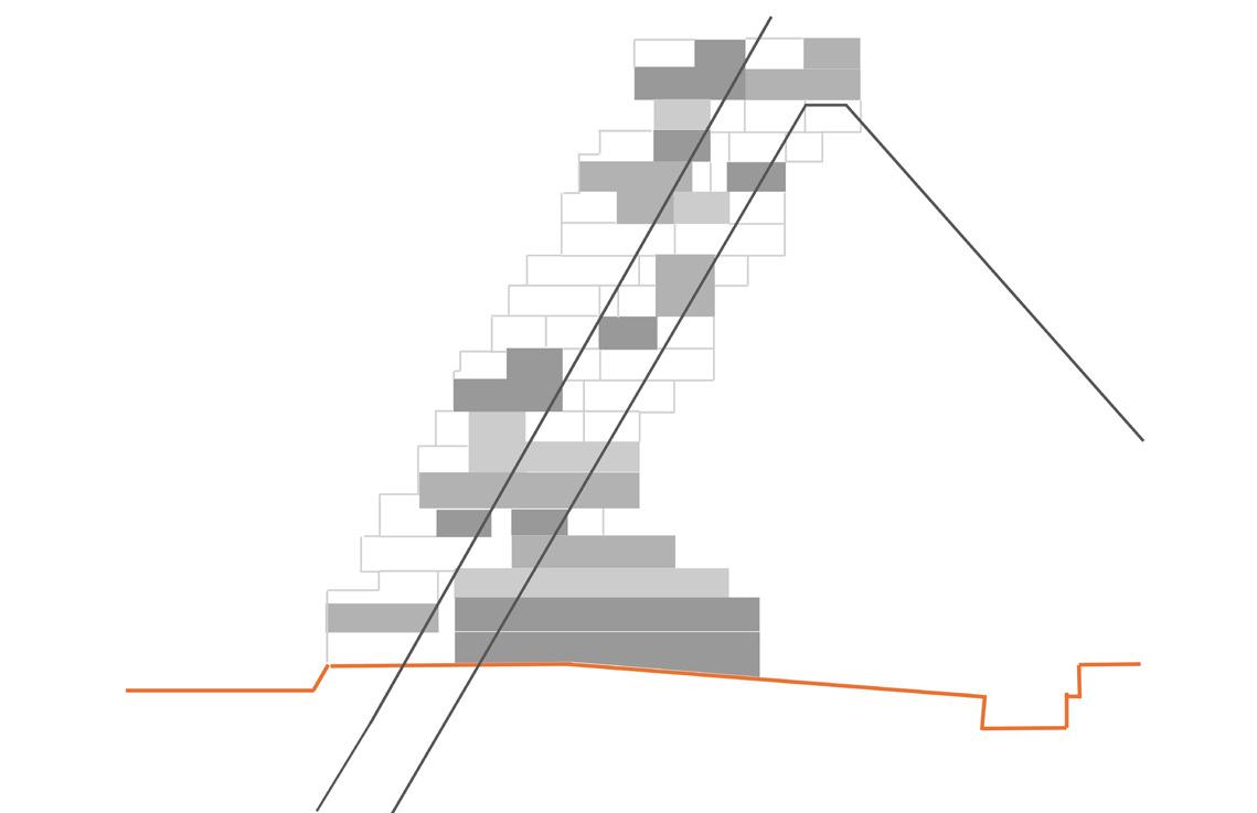
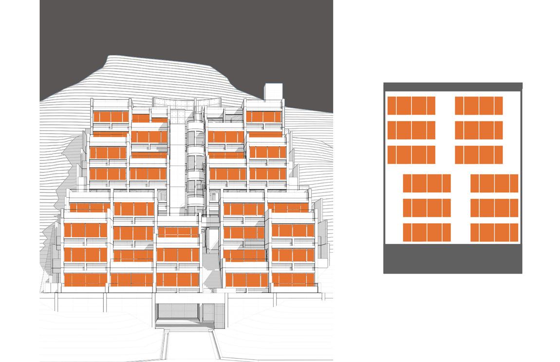
Study of comparision between the buildings by precedent architects
50 Tectonics in Architecture
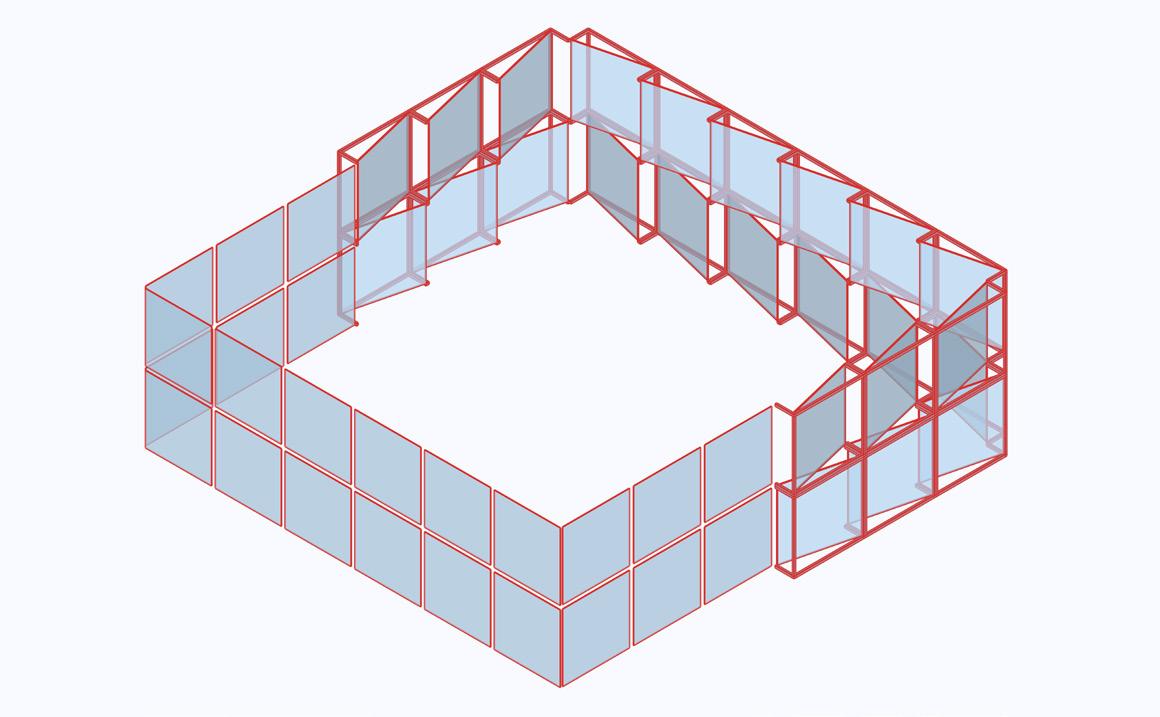
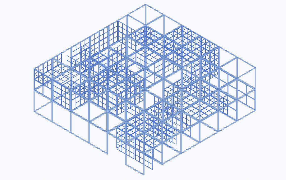
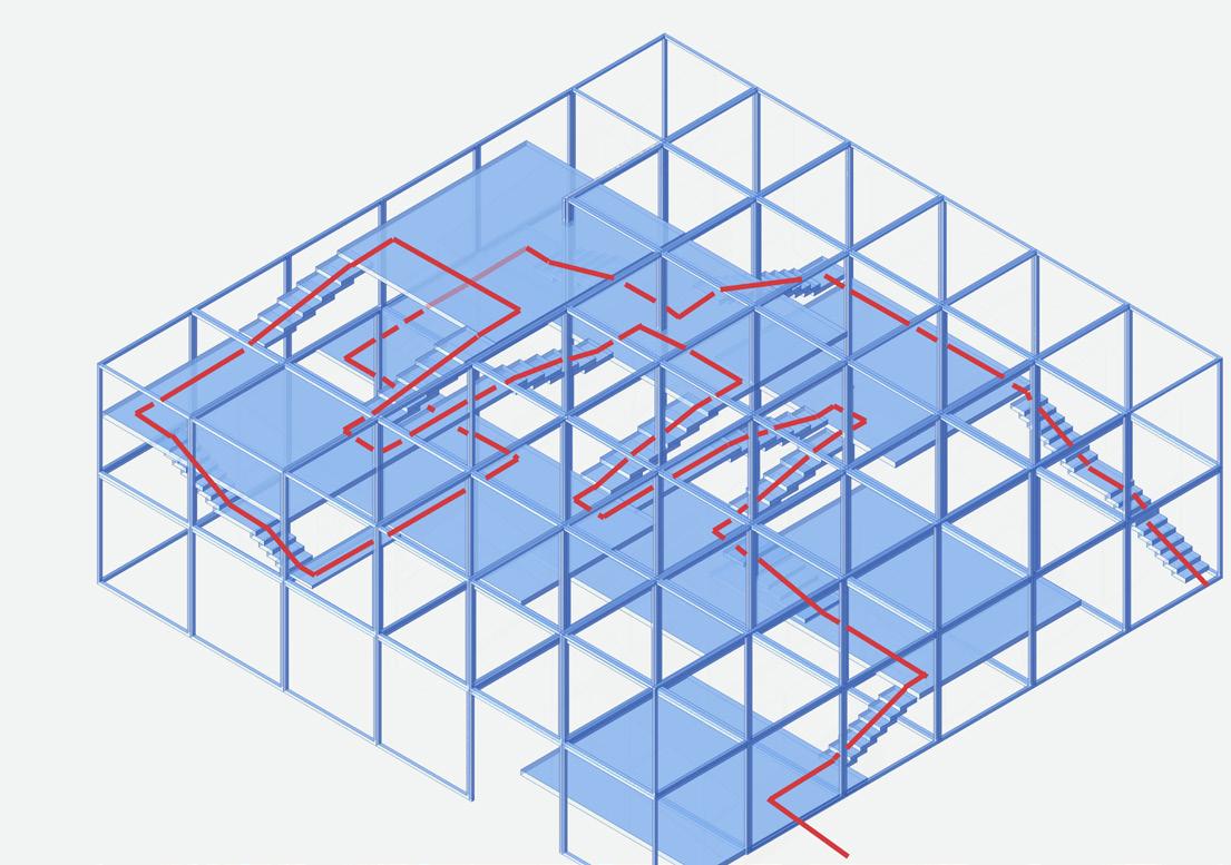
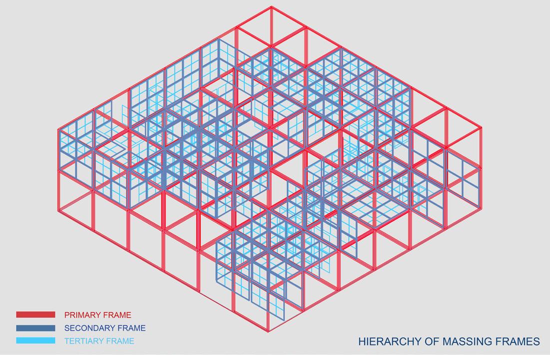

51 Tectonics in Architecture
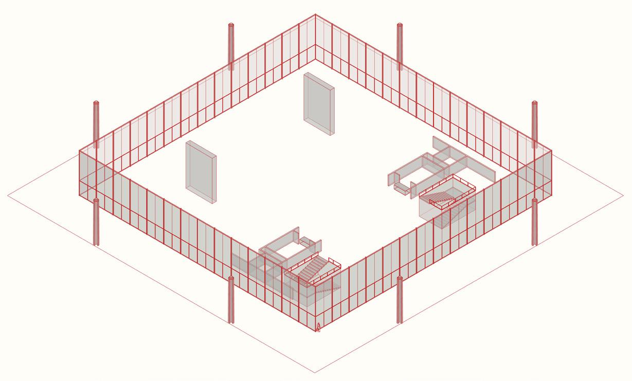
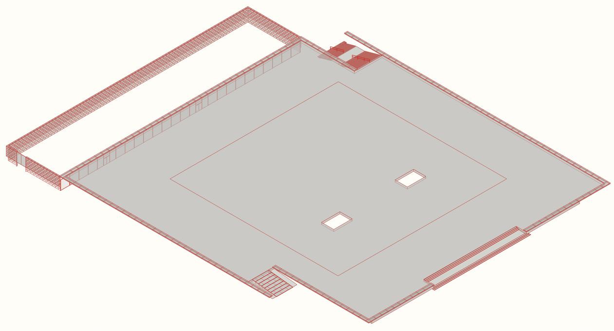
Existing Structural elements of neue National Gallery


52 Tectonics in Architecture
Roof Grid
Transparent Walls
Floor Plate
Module 2
Module 3
Module 1
Exhibit grid derived from roof grid
Peripherial
Peripherial
Fabric as element to diffuse light : Moshe Safdie
Play of facets to diffuse light: Tadao Ando
53 Tectonics in Architecture
core exhibit system derived by he study of diffused light system explored by precedent architect
Exhibit system with fabric canopy derived from the sudy of presedent architects.
54 Tectonics
in Architecture EXPLODED ISONOMETRIC VIEW
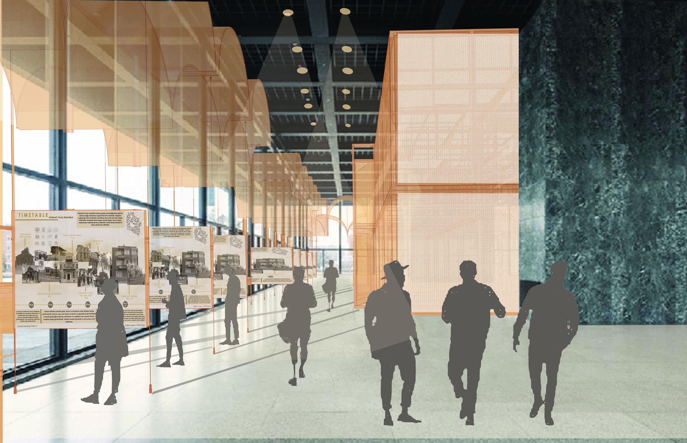
55 Tectonics in Architecture
56 Tectonics in Architecture
Photoshop Collage of the interior exhibit spaces to visualize look and feel
Collage shows the vies from the peripherial exhibit system made of fabric canopy which helps to control the direct glare and light received form the transparent glass wall on the structure.
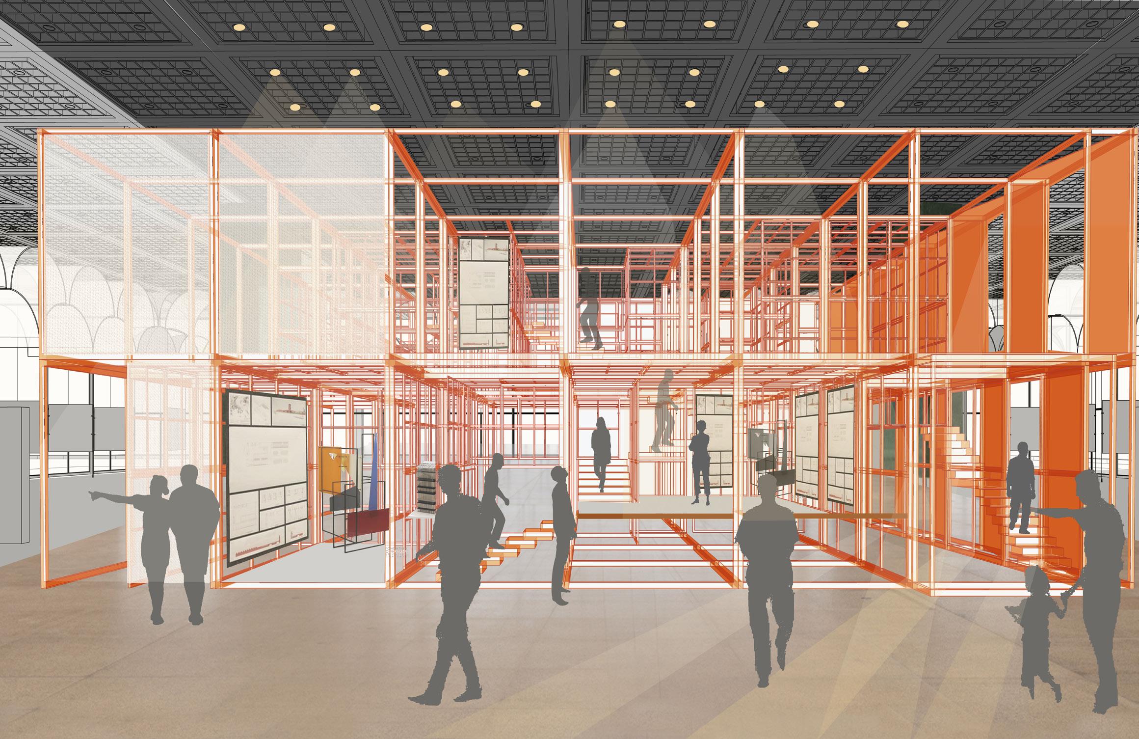
The cuboidal grid derived from the extracting the grid present in roof of neue national gallery and the shiftin the level derived by the proportionsl study of the structured designed by both the architects.
The metal cuboidal frame contrubutes to the material i.e metal members used in the existing site by Mies Vander Rohe.
57 Tectonics in Architecture
Photoshop Collage of the interior exhibit spaces to visualize look and feel
Collage shows the comparision between the fabric element as diffused light and facets on the other side as a diffused light element.
58 Tectonics in Architecture

59 Tectonics in Architecture
60 XYZ of ABC: Wells of Assembly
06
XYZ of ABC:
WELLS OF ASSEMBLY
Academic Project(Spring 2020): Public Space (Shop and Experience center for “WATER”)
Location: Prathma blood center , Ahmedabad
Area: 8000 sq meter
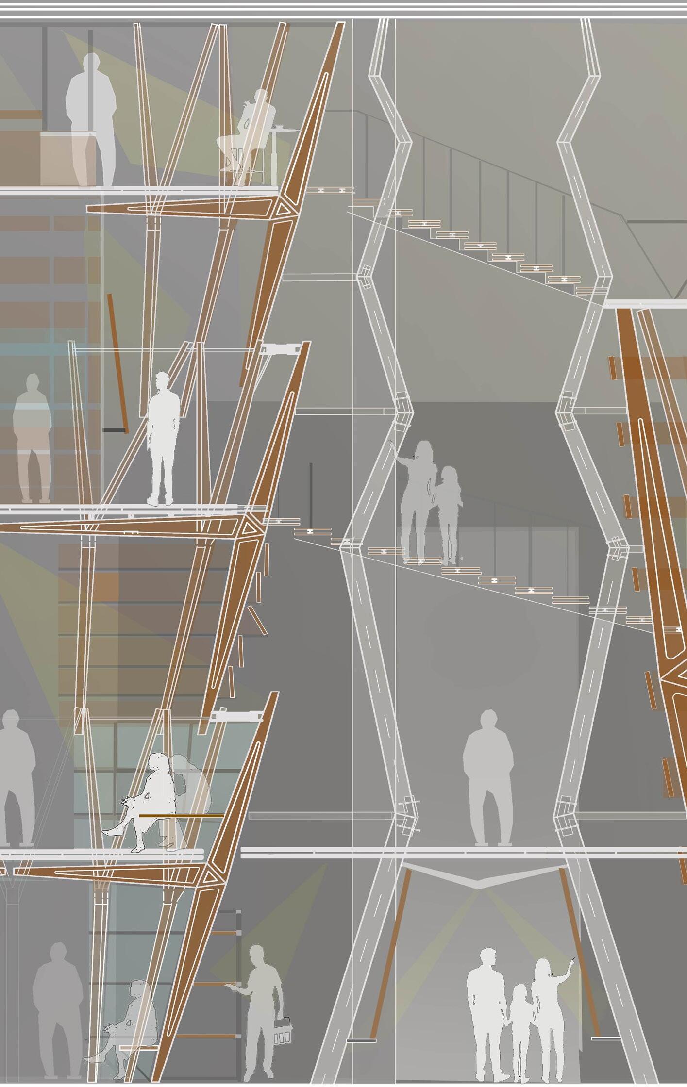
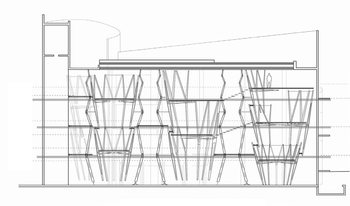
Site clearly has a void spaces formed between the original core working glass box which is wrapped as a skin of intuitive curved concrete walls. The huge 4.5 storey void between concrete curve walls and glass box create a sense of experience of a deep inside the Well from within. Three wells are experienced in the site all which intersects with each other as walls and thus interlocks as a volume at different heights. These wells (curved walls) are of different geometry so forms different scale of volumes. These strong geometry of the site influence the form and design with Kit of Parts.
61
XYZ of ABC: Wells of Assembly | Introduction
Geometry
similar
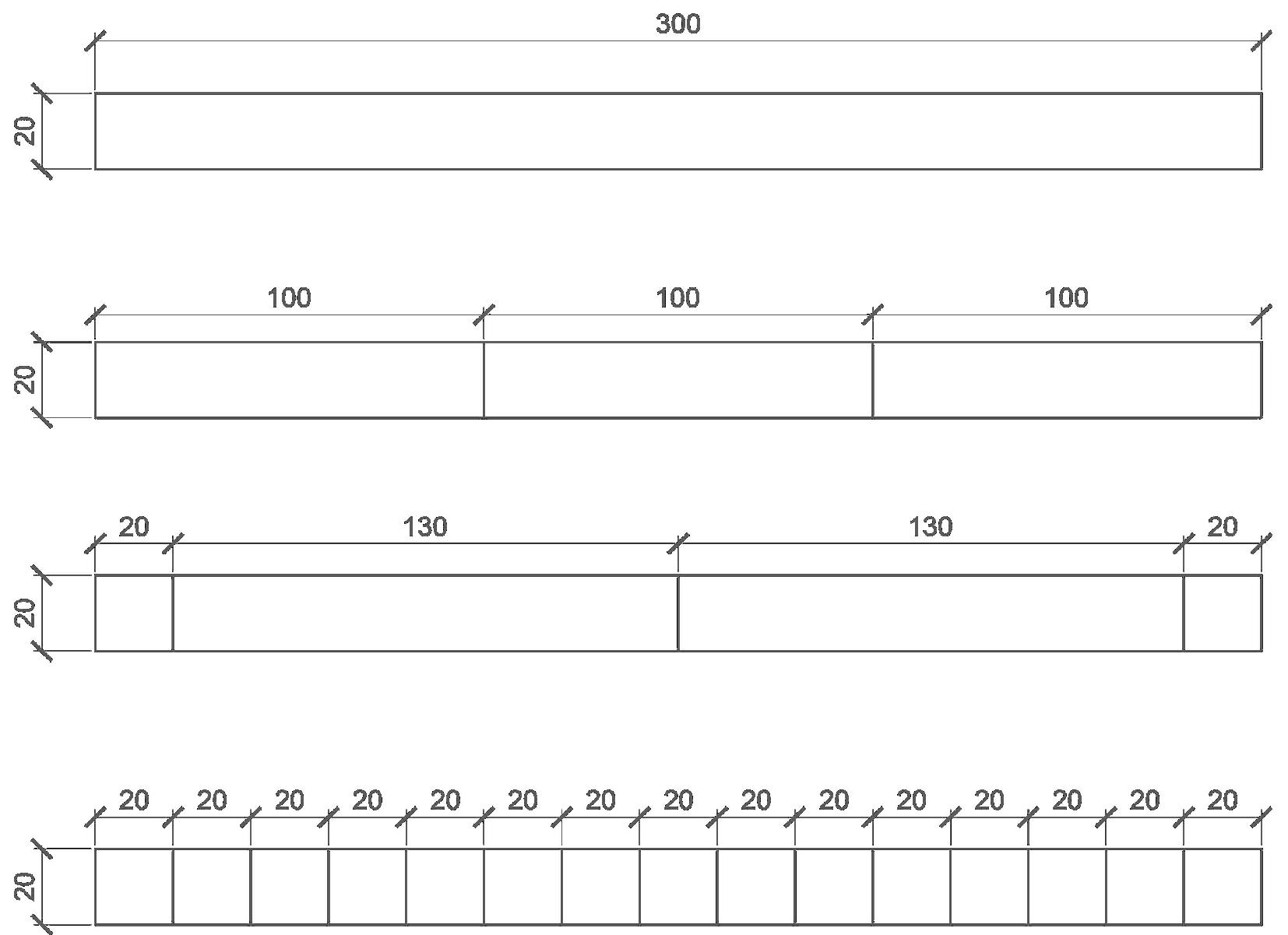
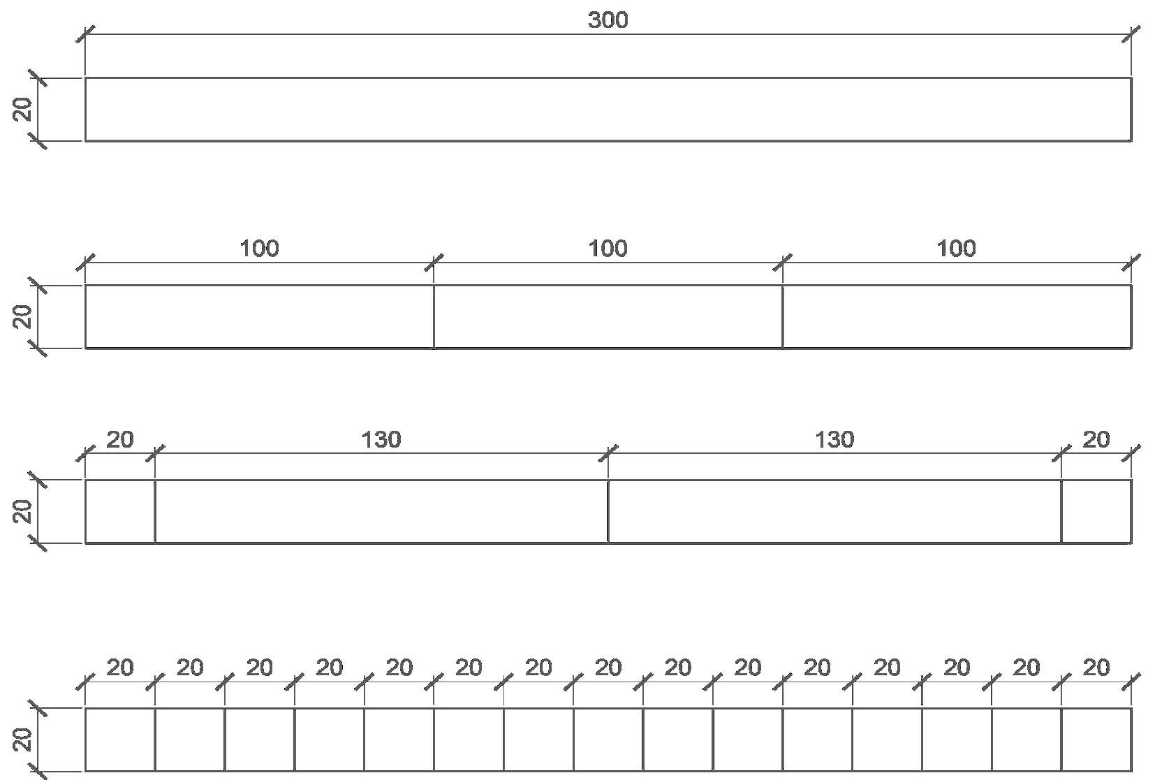
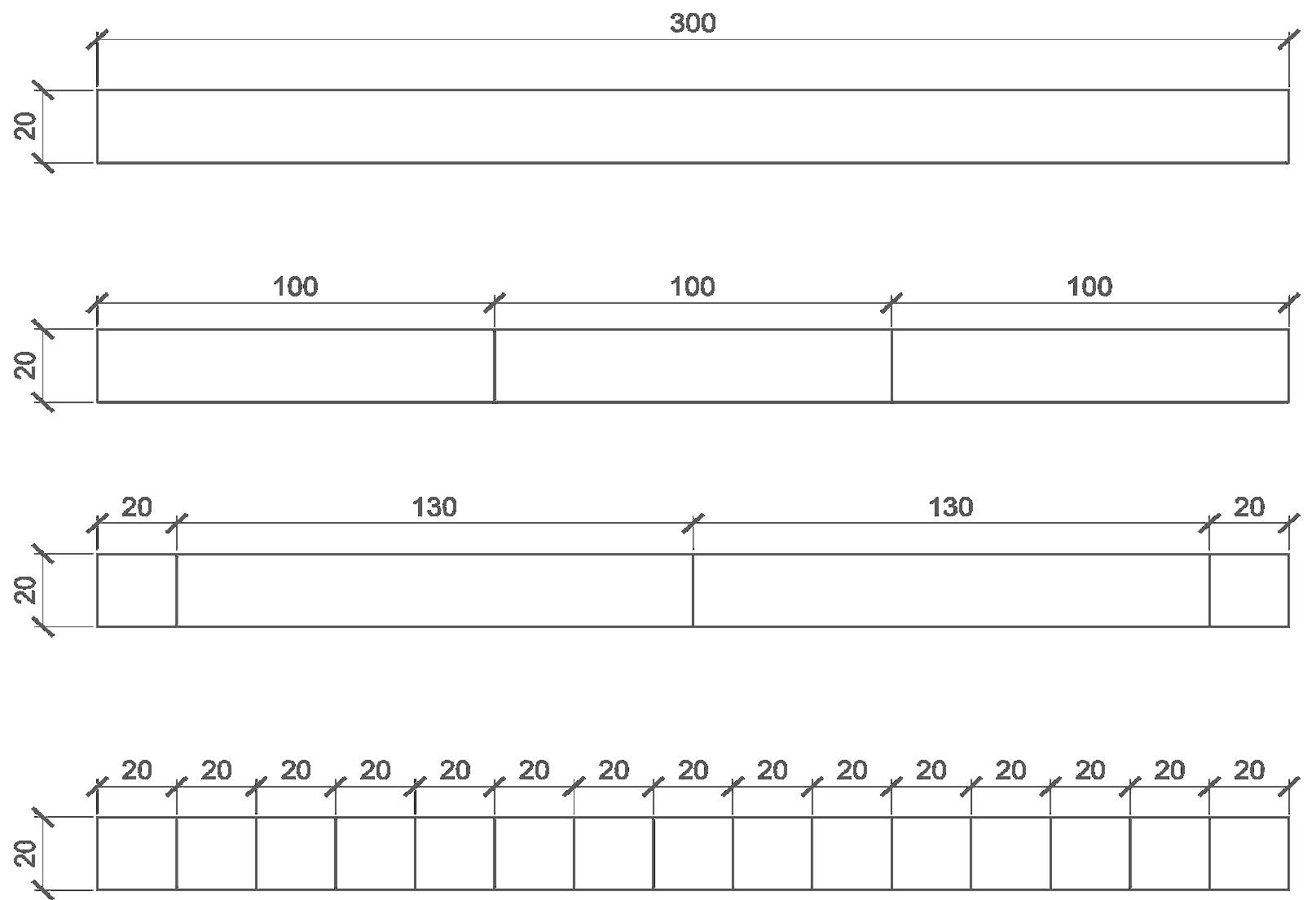
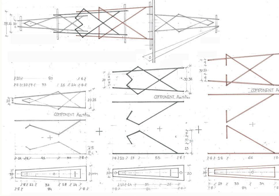
 a. Board (Form)
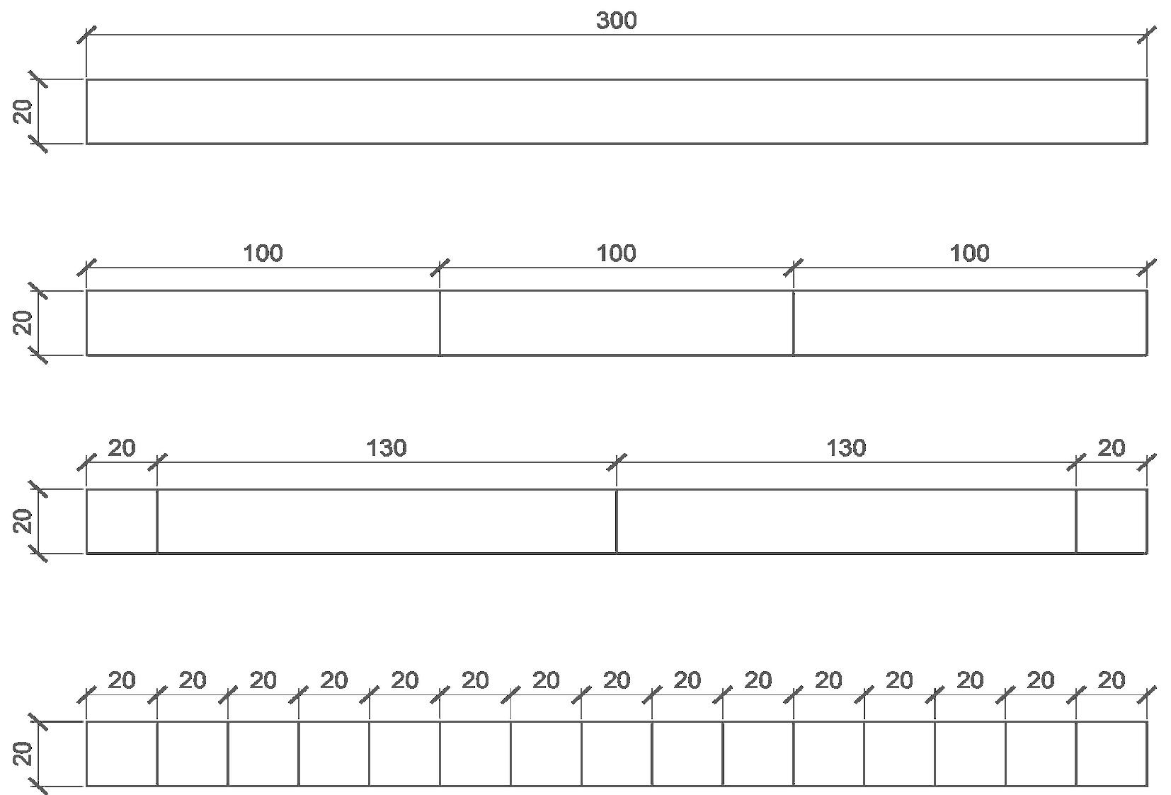
b. Board 50% reduced from original size + String
a. Board (Branching )
b. Board 50% reduced from original size+ String
a. Board (progression)
Form and
of
components for a Cantilever model
XYZ of ABC: Wells of Assembly
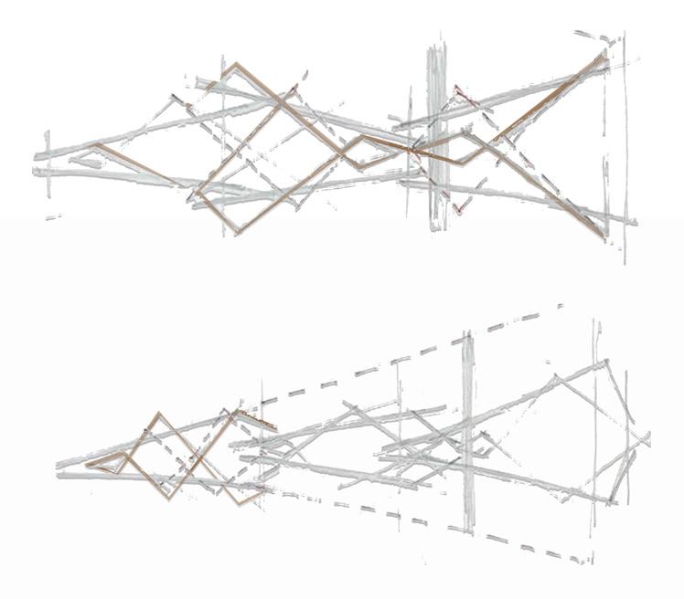
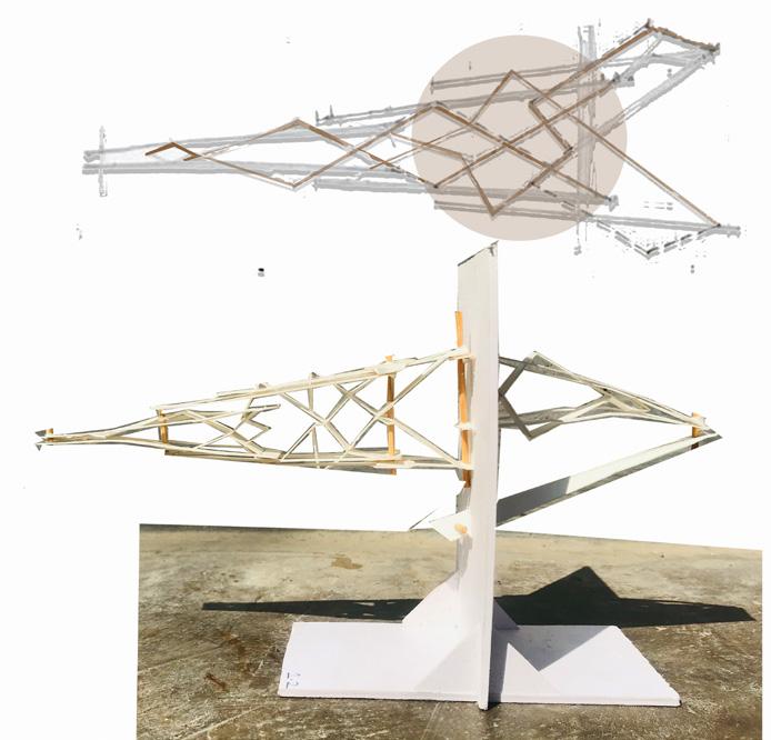
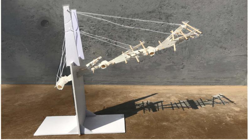
Analytical and Conceptual sketches of a Cantilever model


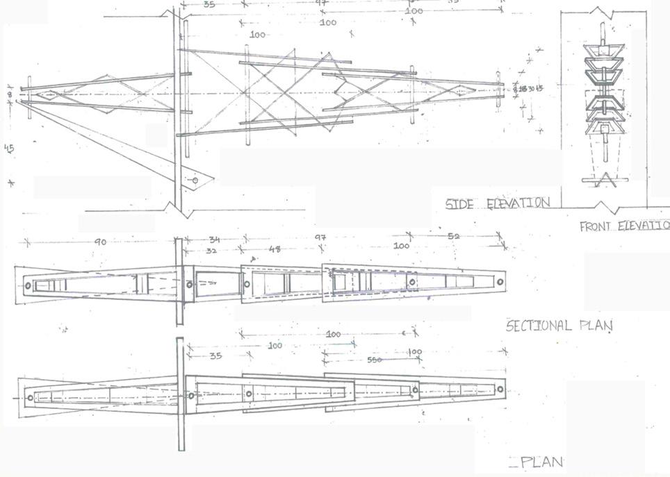
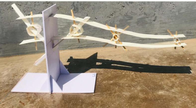
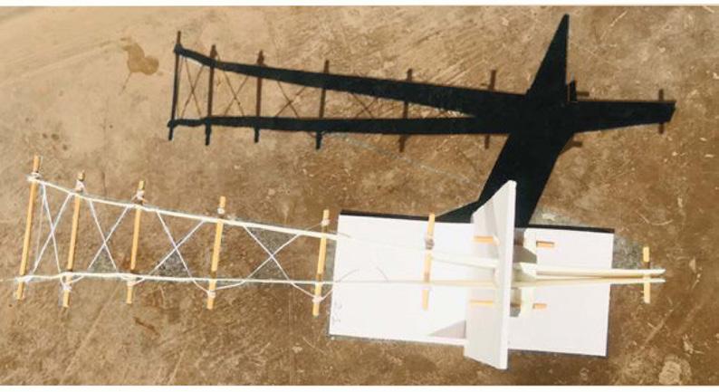
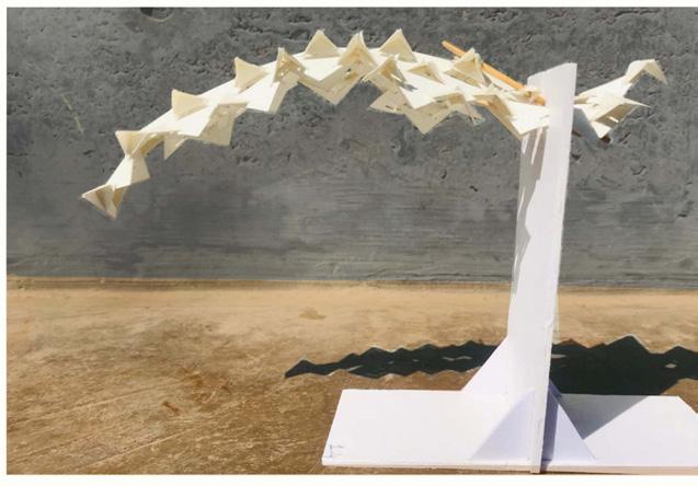
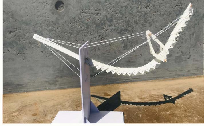
Cantilever Model Study; Form, Geometry, Structure and Proportions
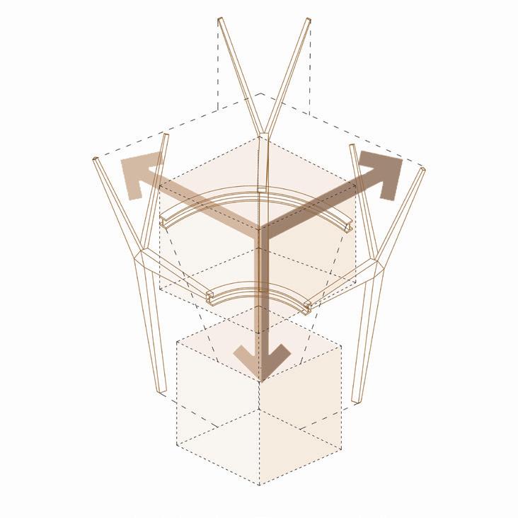
Brief : Analyzing and studying the forces diagram for bending , torsion, shear and co mpression and understanding the role of each part given in designing the system such as stringer, stud, connector, bracing etc.
Learning Outcome: Form and Shape of element is very important part in order for a structure to be stable. Shaping the Kit of part should be such that it gives Form to the structure along with stability keeping in mind the material optimization.The role of same kit of part for making same, similar and different component to assemble a structually stable System.
Study of the sizes and proportions of a cantilever model Exploded Axonometirc view of the assembly of a cantilever model Component
b. Board 50% reduced from original size + string x 3
63
x 3
model
of ABC:
Assembly
XYZ
Wells of
A
B
1205.31 1208.3 1208.97 1210.17 1206.61 1217.1 1210.8 1199.69 1287.01 730.75 677.58 787.7 749.68 650.62 681.92 692.96 728.93 R26.86 R26.86 R26.86 R26.86 R26.86 R26.86 R26.86 R26.86 R26.86 163.5 1185.13 1200.41 1207.53 1209.08 1209.44 1152.23 1094.53 1005.8 11131.28 1161.61 1304.27 1250.68 1322.27 1264.3 1242.67 1294.37 R8.08 R8.08 R8.08 R8.08 R8.08 R8.08 1247.12 1196.02 1606.25 1606.25 1239.39 1488.47 1330.31 1331.85
: Primary Element Component
: Stiffner Element
Third level +1050 cms
Proposed Floor Levels
Social Well for Water
Water in Agriculture Exibition and small activity.
Hydrotherapy as Activity. Water in Medicines.
Importance of Water in Aquatic life.
Exhibition
Activity for Relaxing mind through water.
Spiritual/Reliious Well for Water
Sound Therapy related to water to concentrate and focus mind in Spiritual way .
Existing Floor Levels
Voids as shop for Water
Juice from Fruits and vegetables. Water from oly Rivers , Lakes etc.
Water with addin special chemical compounds to boost immunity etc
Second level +650 cms
First level +450 cms
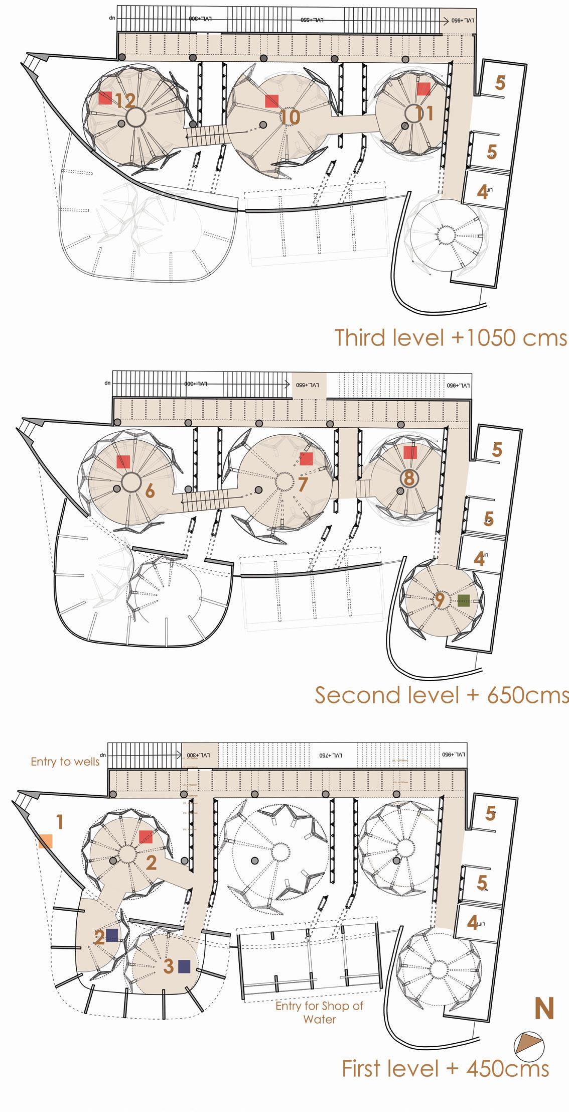
Research Well for Water
Small labaratory with research on water . Produce new products for Shop of Water.
64 XYZ of ABC: Wells of Assembly
Long Section showing Activity in Social Wells i.e Well 1 ,2 and 3 and Shop for Water.Activities such as hydrotherapy center, Exhibition for future life under Water, Activities related to need of water in Agriculture, Cafeteria Etc
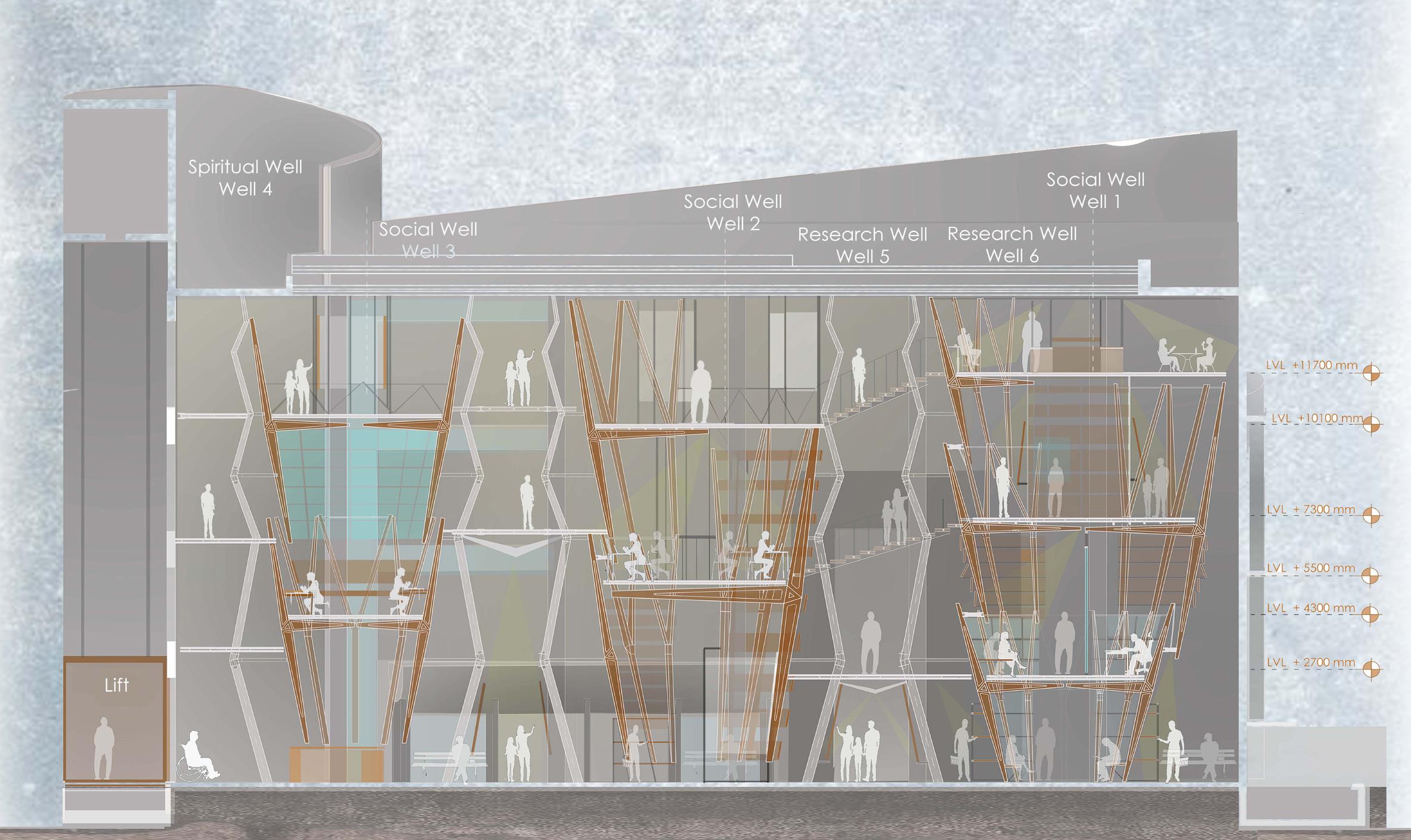
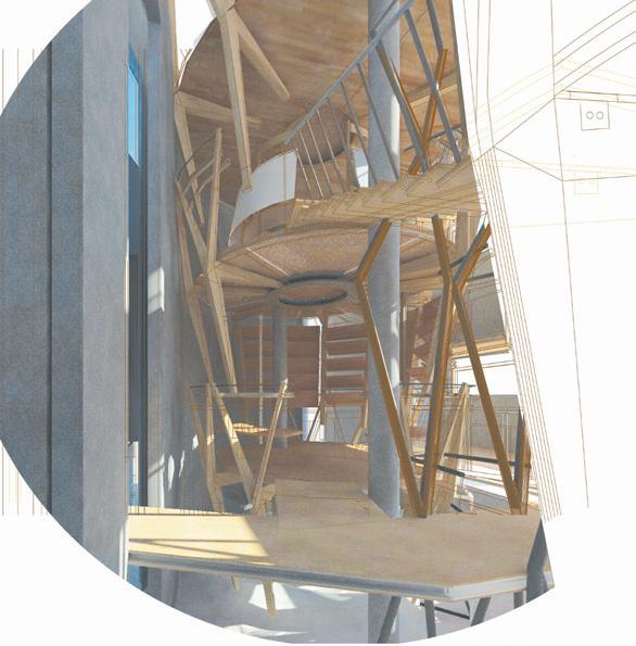
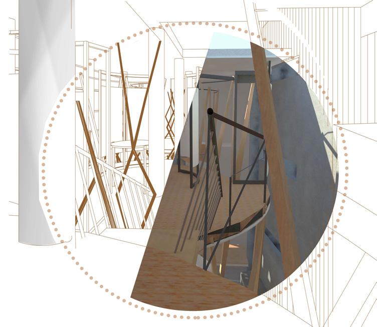
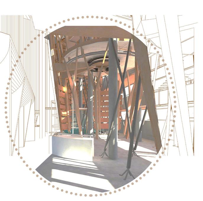
65 XYZ of ABC: Wells of Assembly
View looking at Cash counter from Well2 towards Well1 Exhibition zone in the lowest well of Well2 right at entrance From Shop for Water.
View from Staircase of Cafeteria looking at Exhibition space of Well 2 with Direct light From Roof OTS covered with solar radiant glass.
View from Entry for Shop of Water looking towards Bridge 1 connecting well 1 with Research Well.
XYZ
Vertical Assembly Between components of each System i.e Wells, Bridge and skin.(Inter System) Horizontal Assembly Between each System i.e between Bridge, Well and Skin of Well. (Intra System)
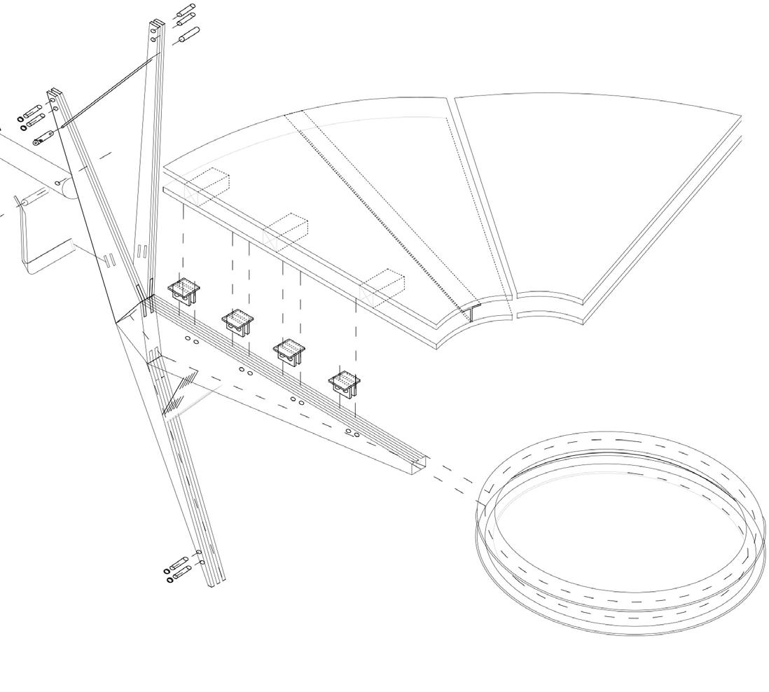
Sandwich slab 200 mm thick 25 mm thick plywood on sandwiched with` T` section of 100 mm flange.
a. 25mm thick plywood
b. 30mm thick wooden stiffners
c. T section with height 100m and 100mm flange.
d. Plywood 25 mm thick divided in 12 equal parts to assemble with the cantilever Member from skeleton of WELL module.
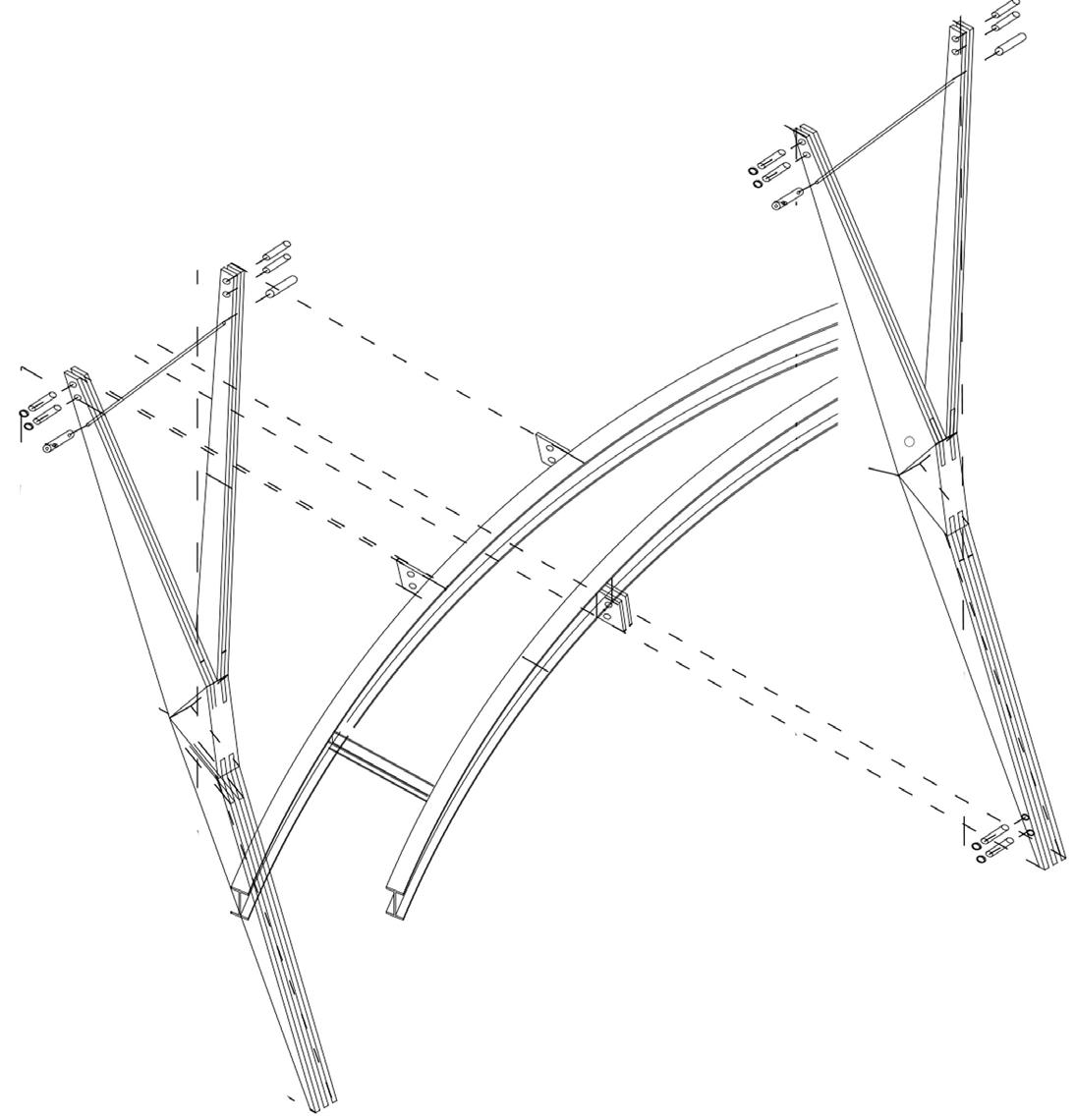
Cantilever Member of Skeleton of Well tied togeather with an I section Ring of 150cms Diameter.
Branched modules of skeleton of Well tied togeather with a 60mm dia rod in Tension.
Assembling the modules of two different Subwells with a ring of I section running around lower periphery of upper Well and upper periphery of lower well Offsetted from each other to allow light to pass through from top to Bottom.
Scaling the half part of Subwell 1c such that bigger modules becomes a surface for Subwell 1c and floor Supports for Subwell 1d. Exploded
Primary Structure Suspended Volume Skin and Interior
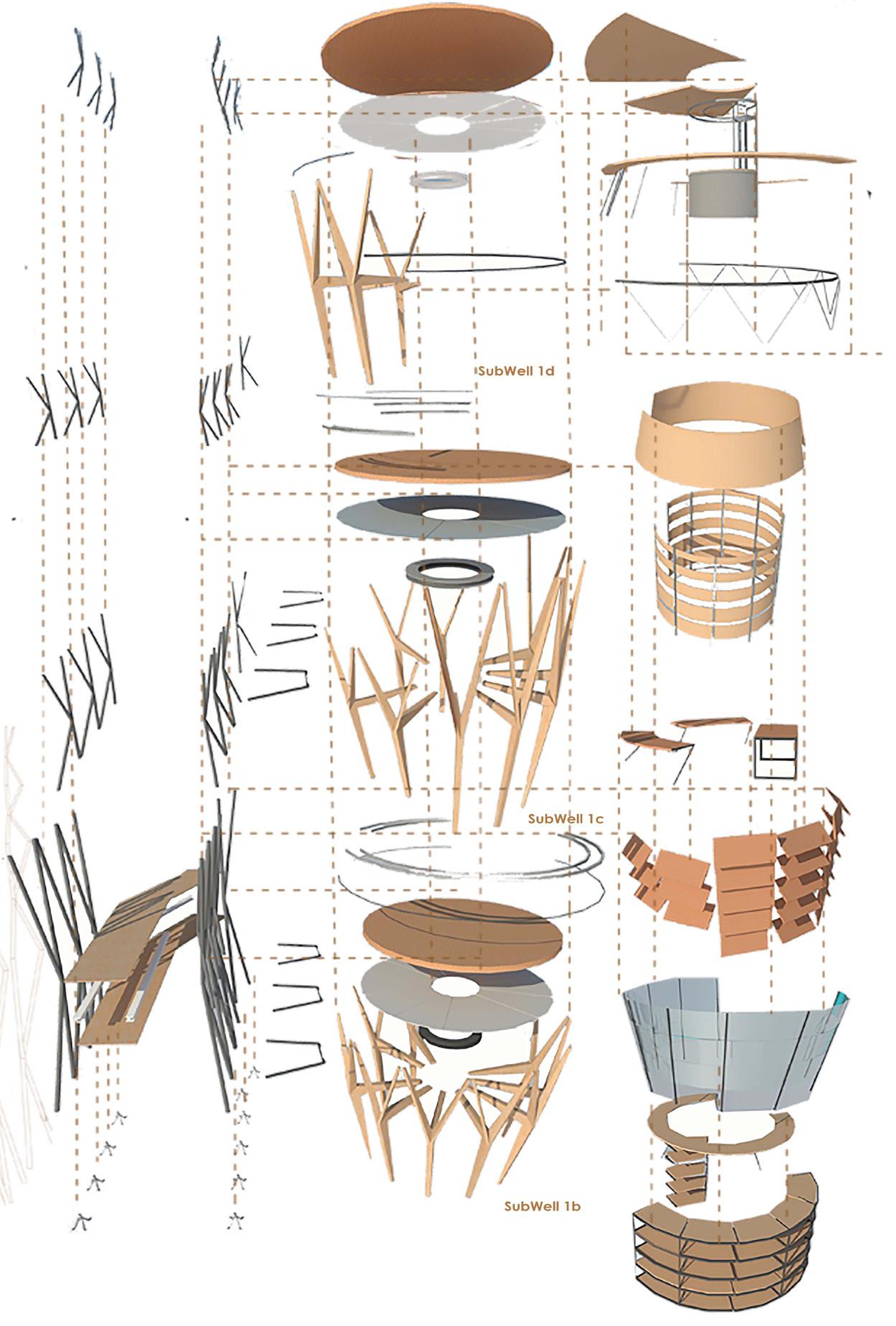
Cafeteria open space as Functional requirement resulted in 4 modules of skeleton . To support structure central kitchen counter with structure to support the upper modules of skeleton of sub well 1d.
High stool sitting tabletop around the periphery to again supported open Structure of Sub well 1d.
Railing as a structural member tying floor with lower module of Skeleton of Subwell1 d.
Exhibition Panel for display of Exhibition on Future /Aquatic Life under Water.
Structure for Display of exhibition is an offset of Form of Well which partially transfers the load from Floor of Well 1d towards well 1c and further down.
Semi open space as a functional requirement to allow controlled light and vision in the space.
Waiting Area for appointment for hydrotherapy Center. Space with controlled light and vision.
Privacy as a key factor to this space. So skin as louvers which ties each module of sub well 1b and also allows controlled light entering the space.
Sitting is such that it again ties the Sub module of Sub well 1b. (Smaller modules of Sliced Form).
Display rack for shop of water is such that it surrounds well modules and act a a bracin and tied member for modules of Well ,which helps to transfer the load to round
66
of ABC: Wells of Assembly
View of an Order Of Assembly of Wells with bridge and Interior Elements
Assembly of well 1 with bridge connecting well 1 (Social Well and Research Well)
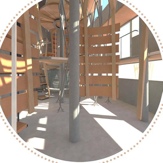
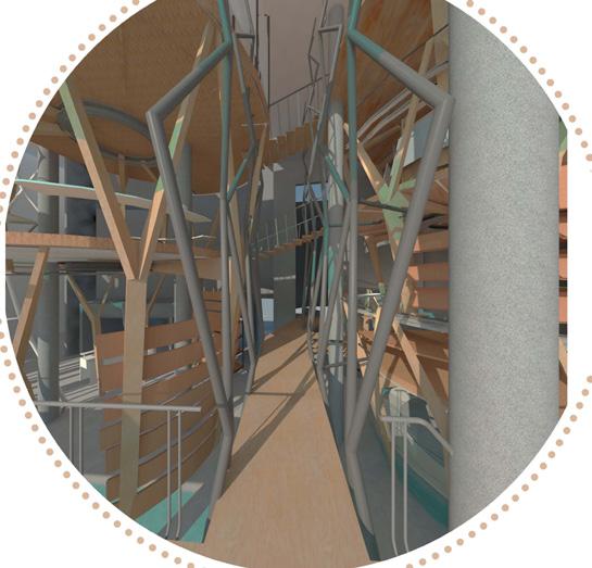
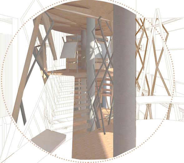
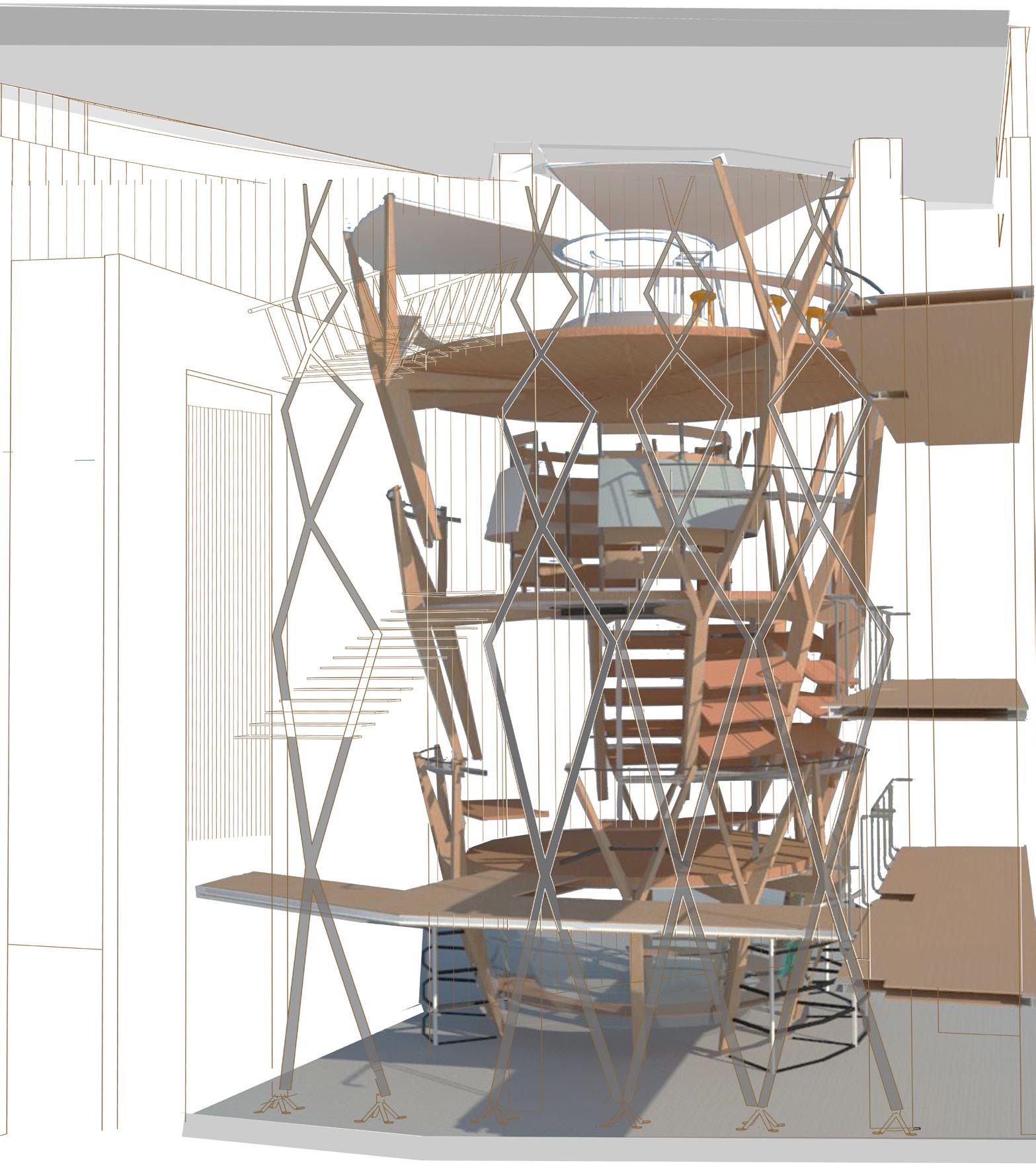
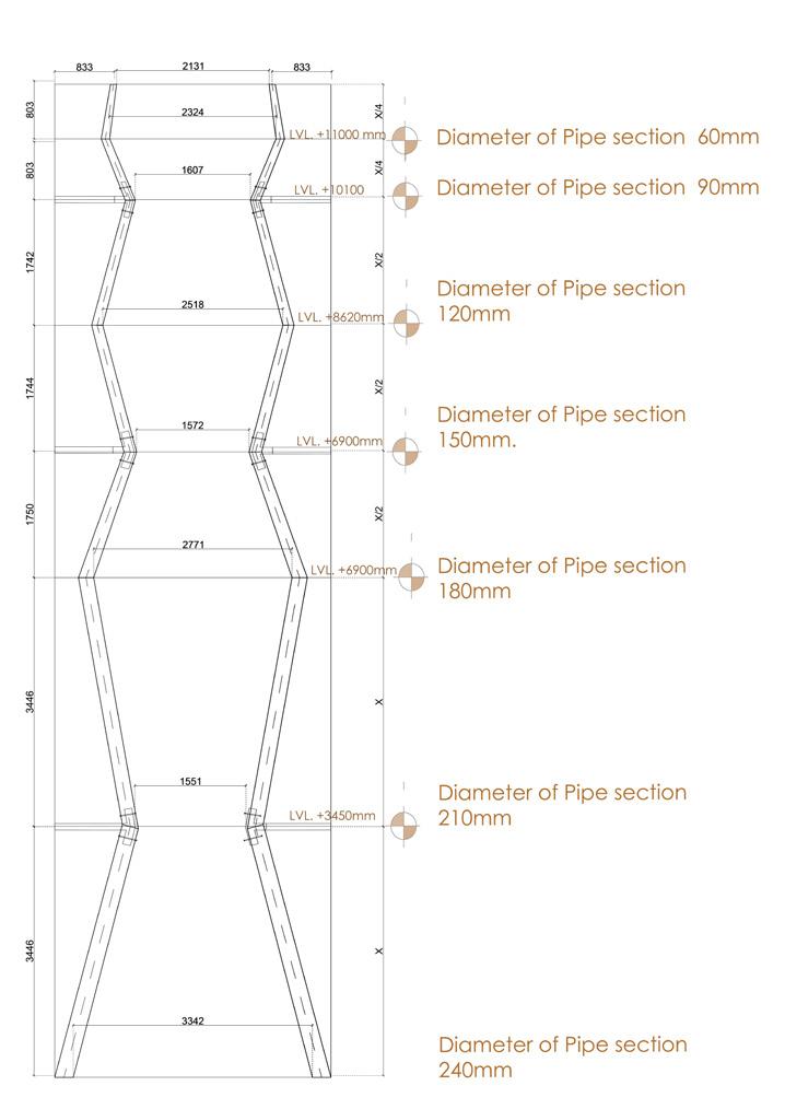
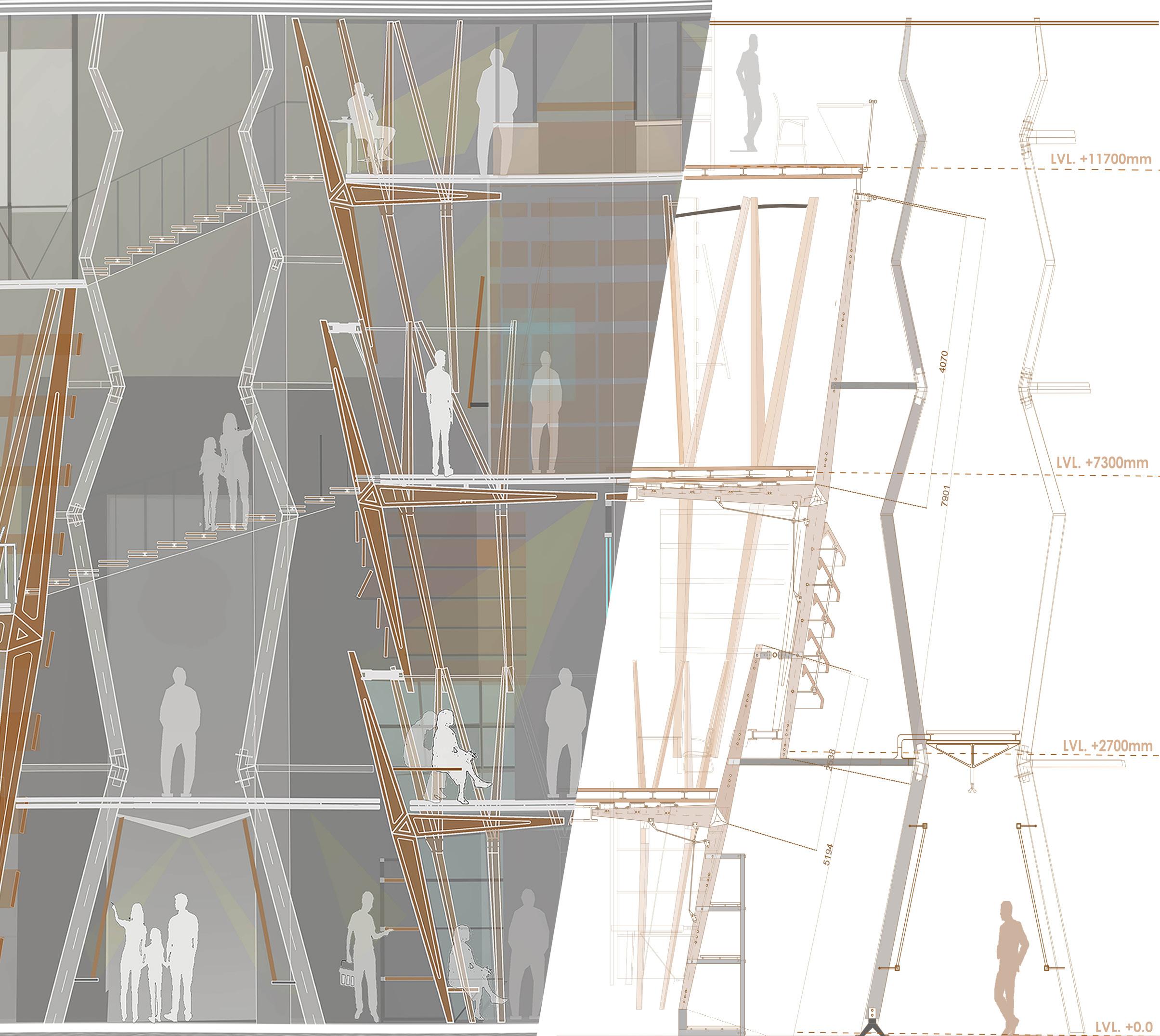
Number of modules reduces and diameter increases moving upwards such that the curved surface of Site becomes a backdrop skin for subwells.
The density of members reduces moving upwards and functions are distributed such that least private spaces are planned at most top.
Skeleton of Well 1 + skin for each Well such that it becomes the Secondary Structure. Primary Frame of compression members spanning vertically to support bridges for circulation and suspend two Primary wells on both side of passage.
Bridge connecting Well1 of Social Well and Well 5 of Research Well
67 XYZ of ABC: Wells of Assembly
View from subwell 11b looking towards through louvers at bridge .
View from Bridge 1 connecting social well with research well with compression members of bridge anchored with well modules to suspend well.
View looking at Cash counter from Well2 towards Well1 Exhibition zone in the lowest well of Well2 right at entrance From Shop for Water.
XYZ of ABC: Wells of Assembly
Well 1 showing the quality/Ambience of interior space along with interior elements such as louvers. railings, glass cubicle, Sitting elements, Shop display element, Exibition Dispaly etc
68
Spacer between compression member (40 mm dia x 160 mm)
Tension rod (between 2 spacers)
Wooden sections 20 mm thick
“I” section (100 mm web) 50 mm flange circular bent in 4 quadrant.
“I” section( 80 mm web) 40mm flange for bracing two sections
Metal Gusset plate 45mm thick between wooden planks
Wooden Plank(triangular shape) 60 mm thick
Metal Plate 25 mm thick
Wooden sections 60mm thick
Isonometric detail of junction of vertical conncection with floor (Well levels).
XYZ of ABC: Wells of Assembly
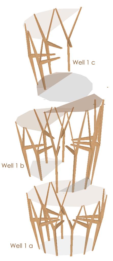
Assembly of Well 1
Component of well 1a, 1b and 1c assembeled to develop a social well system with a combination of wooden compression member elements tied with metal rod which act as a tension member.
Social Well 1
Circular pipe 80 mm dia as junction for well with bridge 20mm plywood sandwich
I section (80mm web) 40 mm flange sandwich between plywood
T section with double web (100 mm) flange (100 mm)
20mm da holes for fixing cantilever wooden beam with sections.
DETAIL 2
Isonometric detail of junction of vertical connection of two same members of different volume of wells.

Sectional Perspective
69
Detail B DETAIL 1
70 Interpretation Center | Introduction
07
Interpretation Center
Academic Project ( Spring 2018) Interpretation center for archaeological remains of Dholavira
Location: Dolavira Excavation Site , Gujarat
Area: 10,000 sq feet
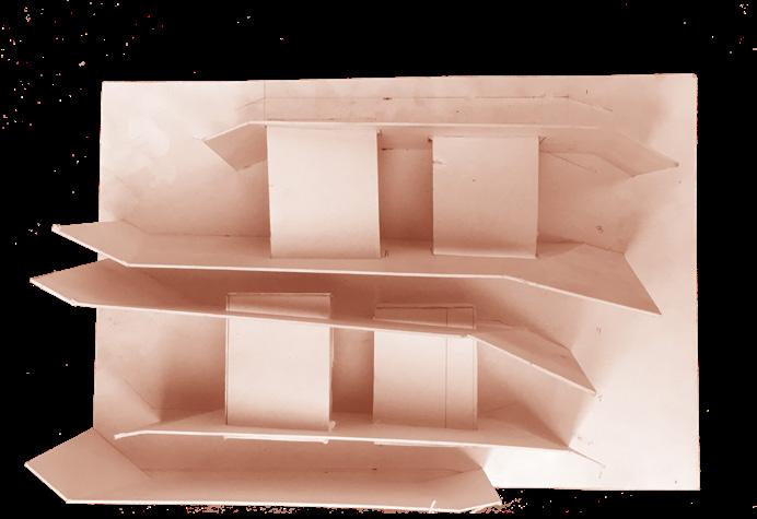
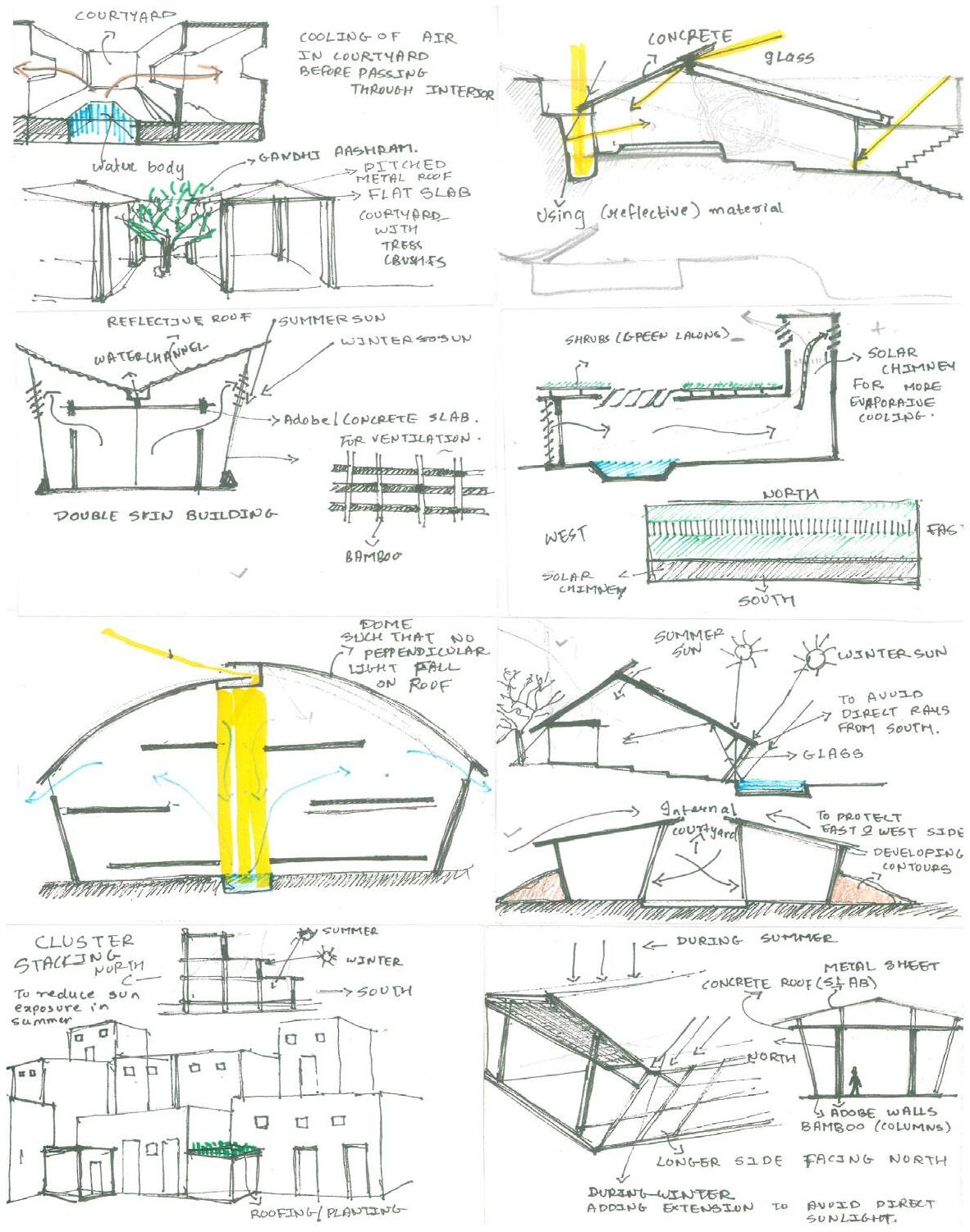
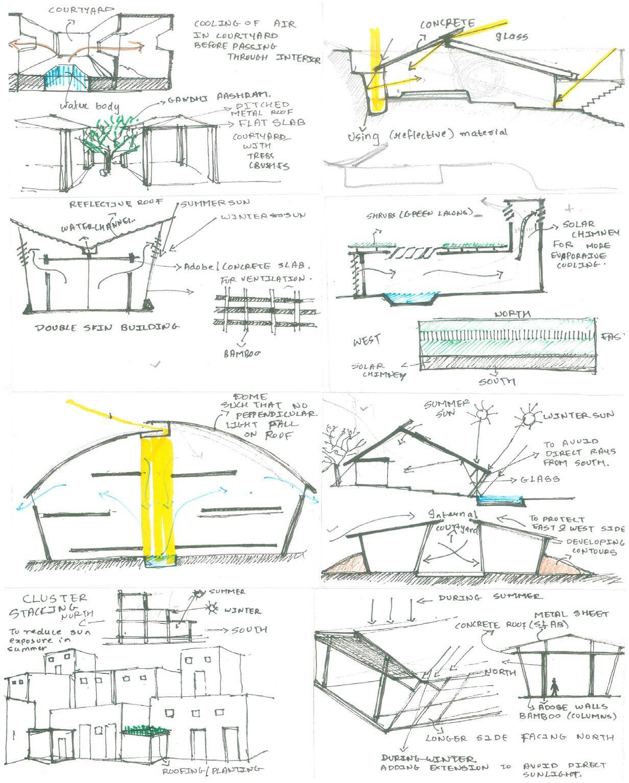
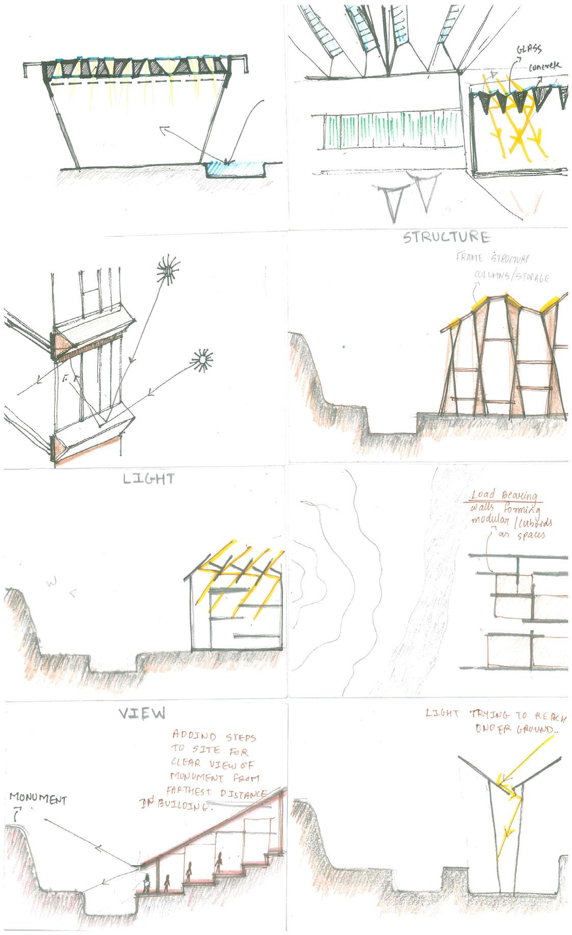
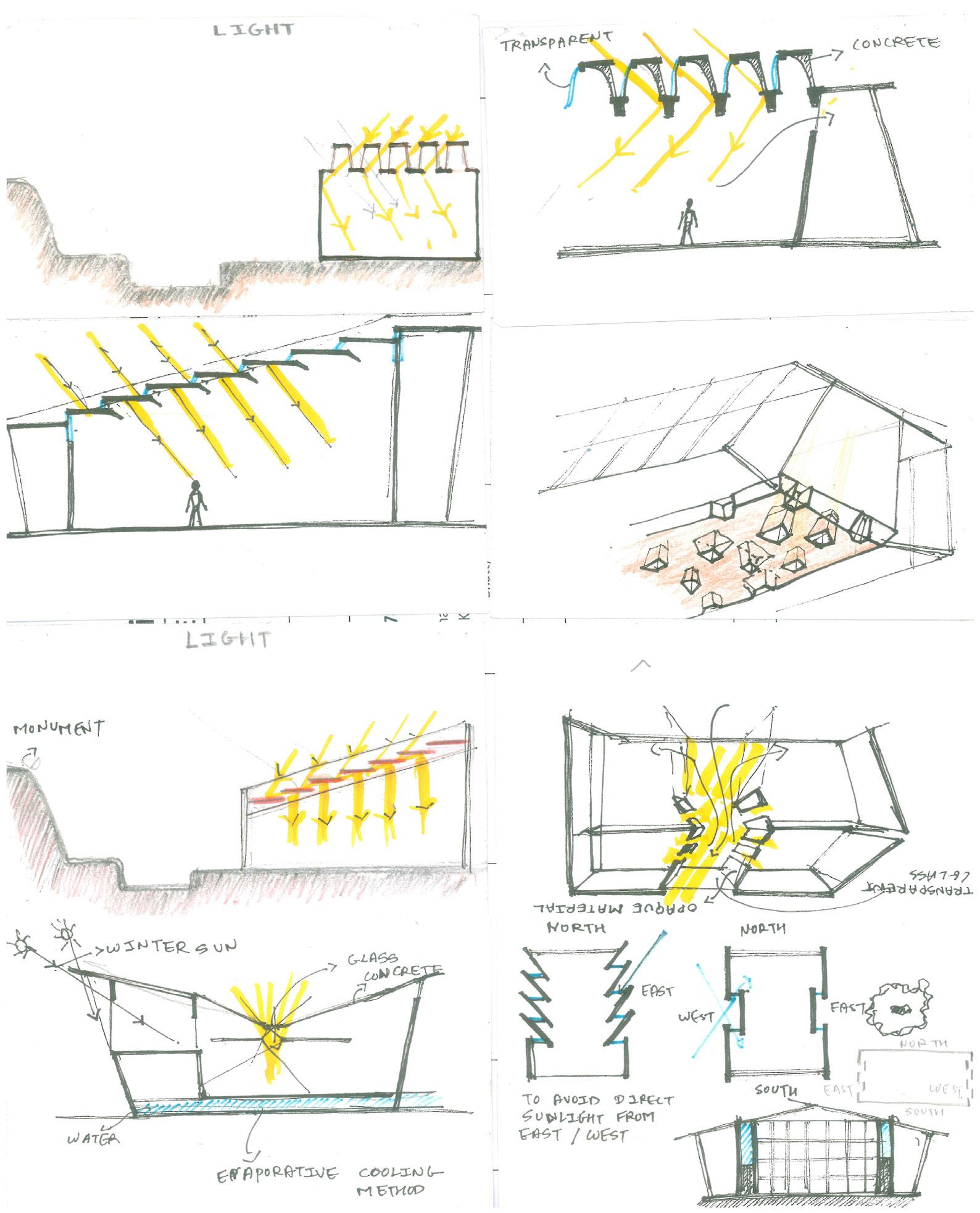
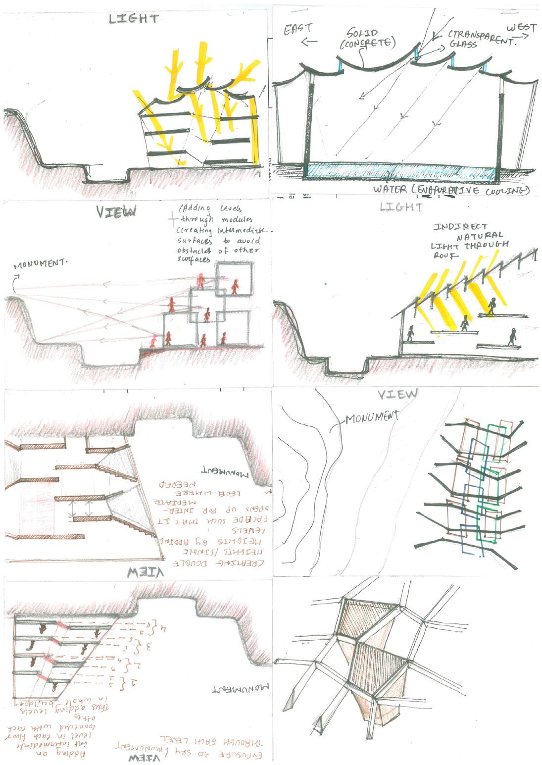
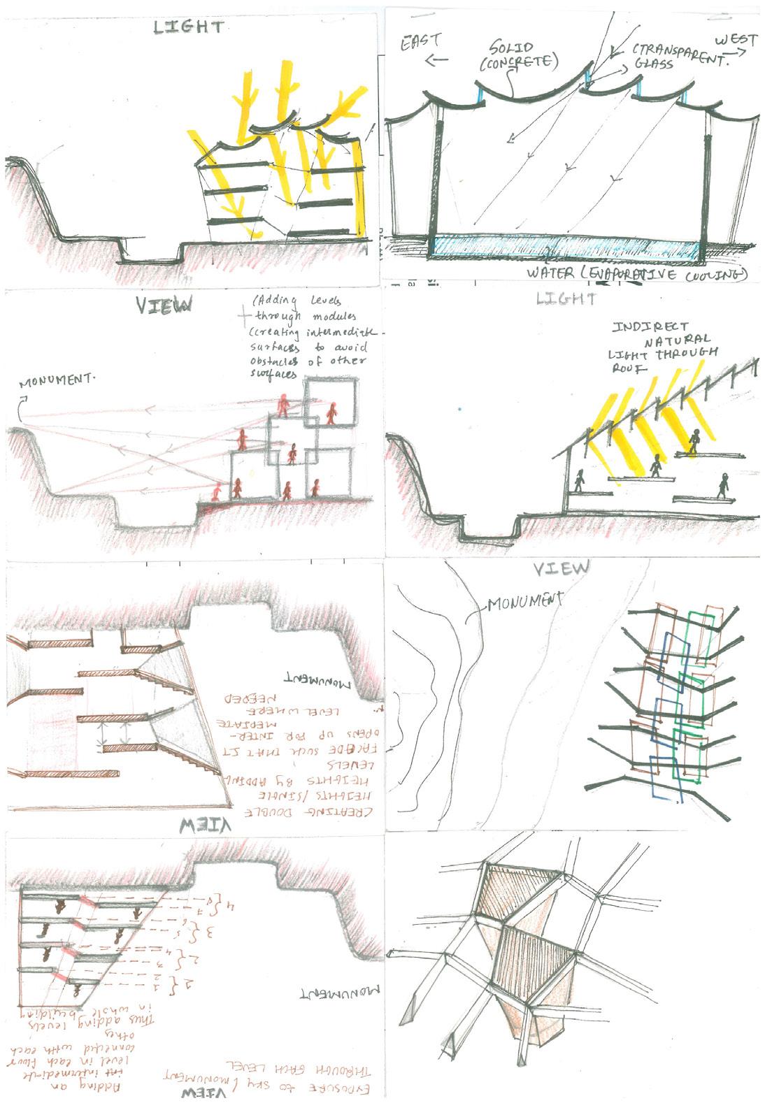
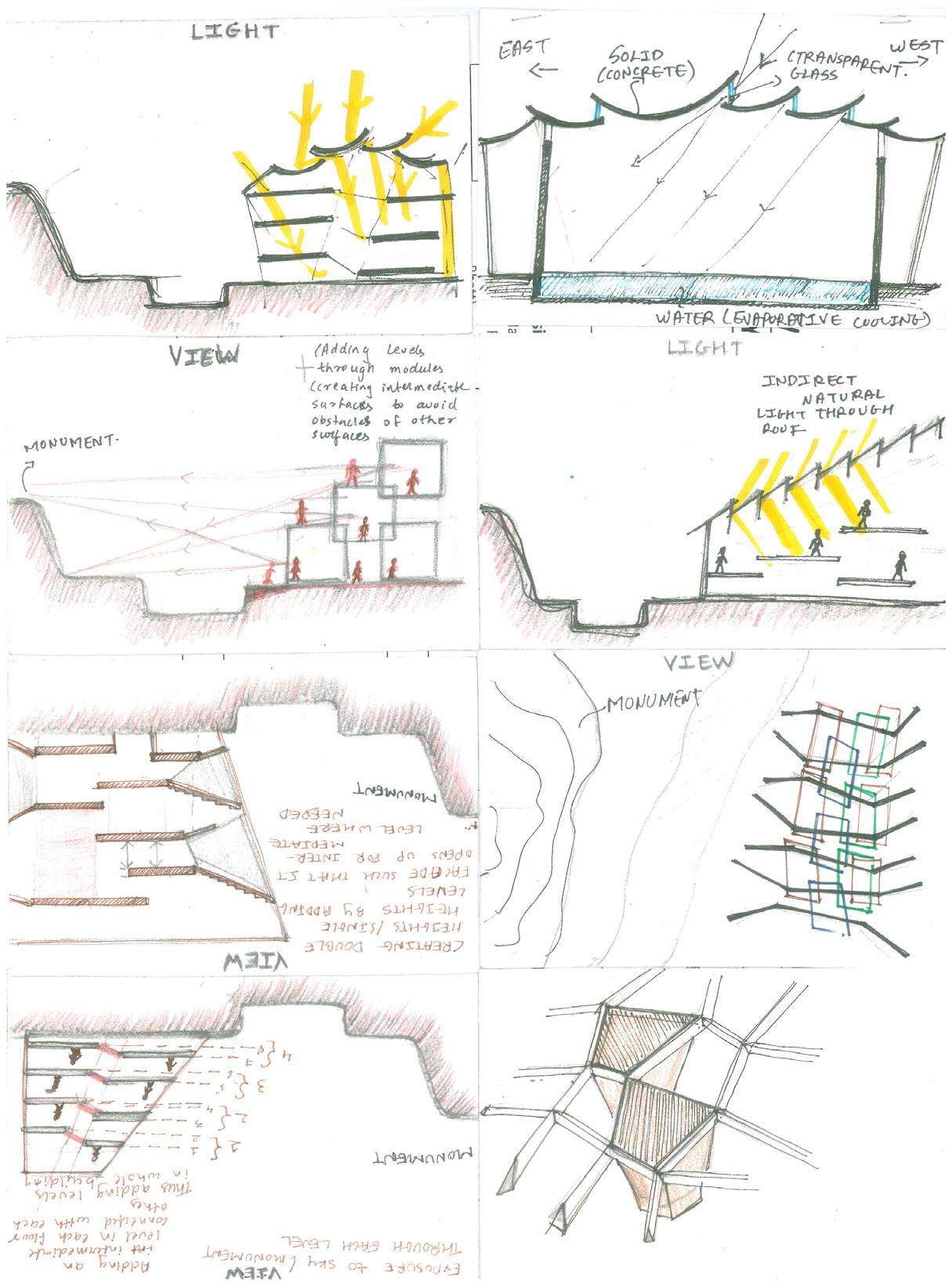
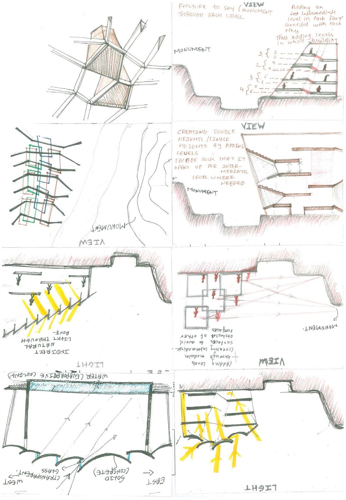
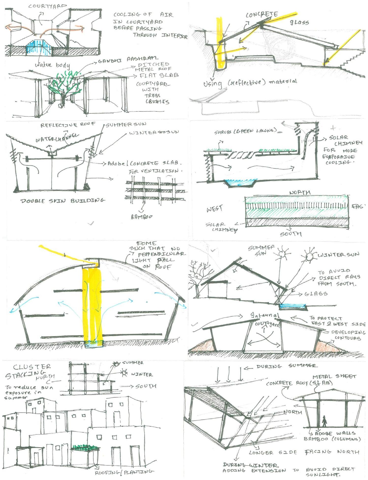
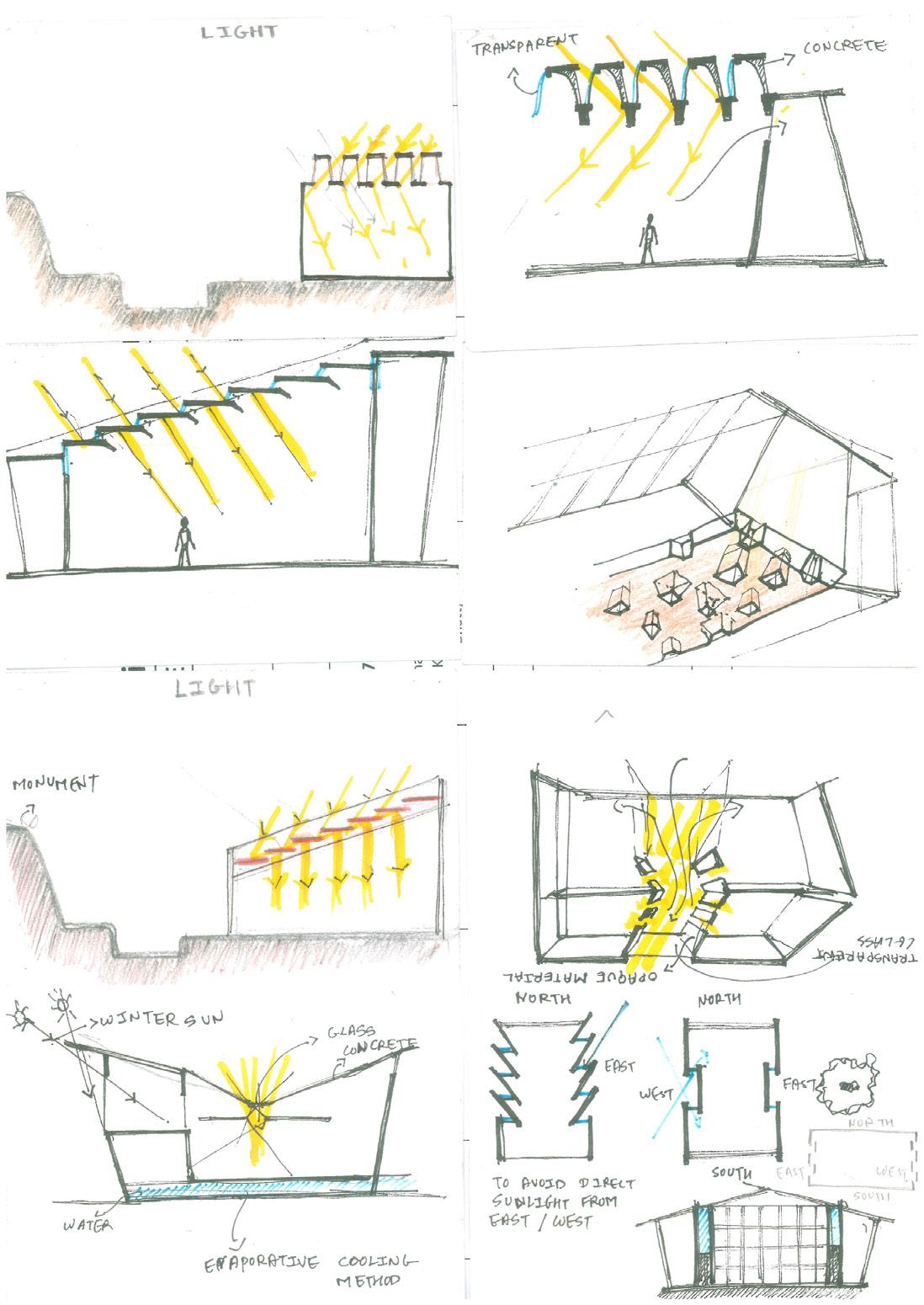
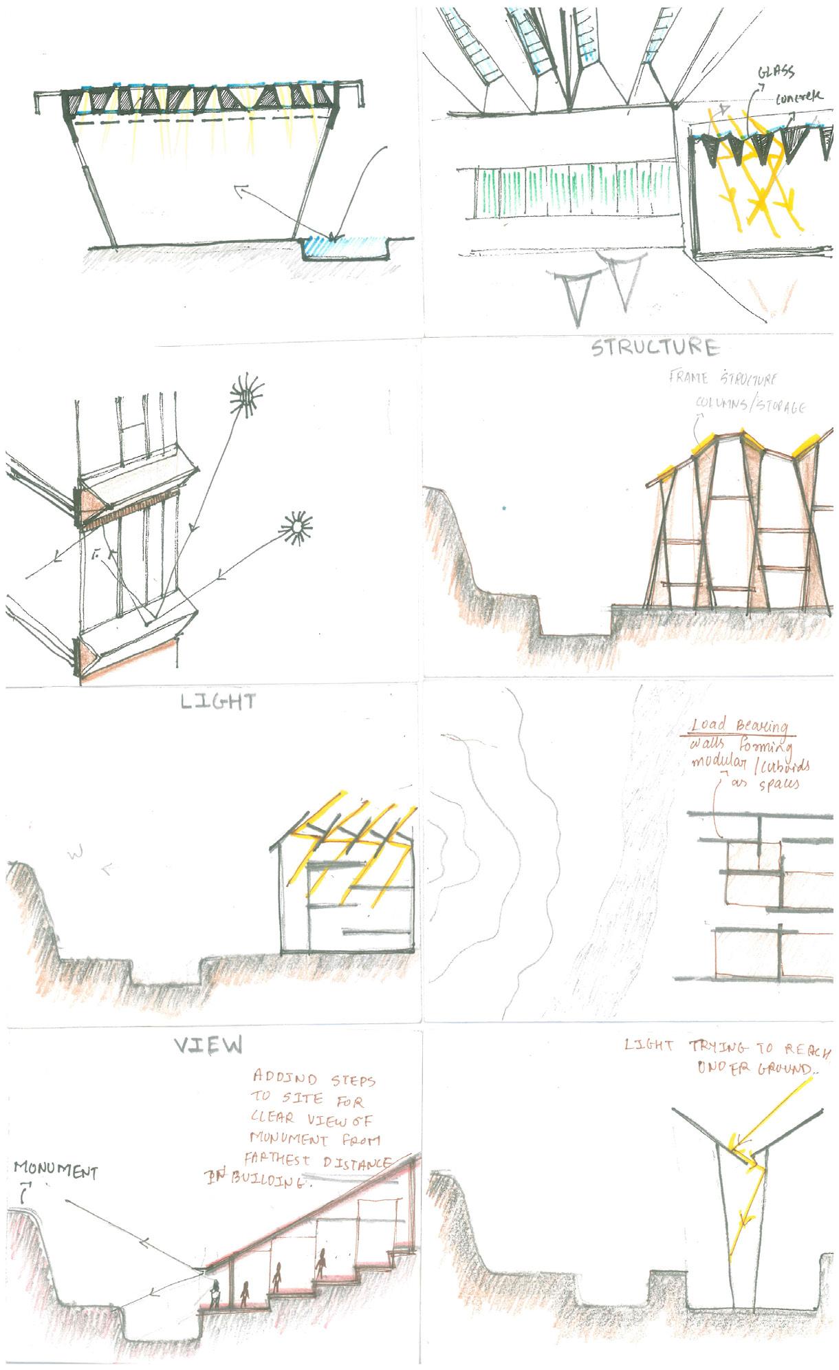
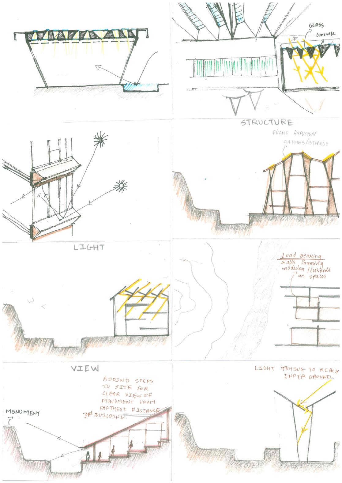
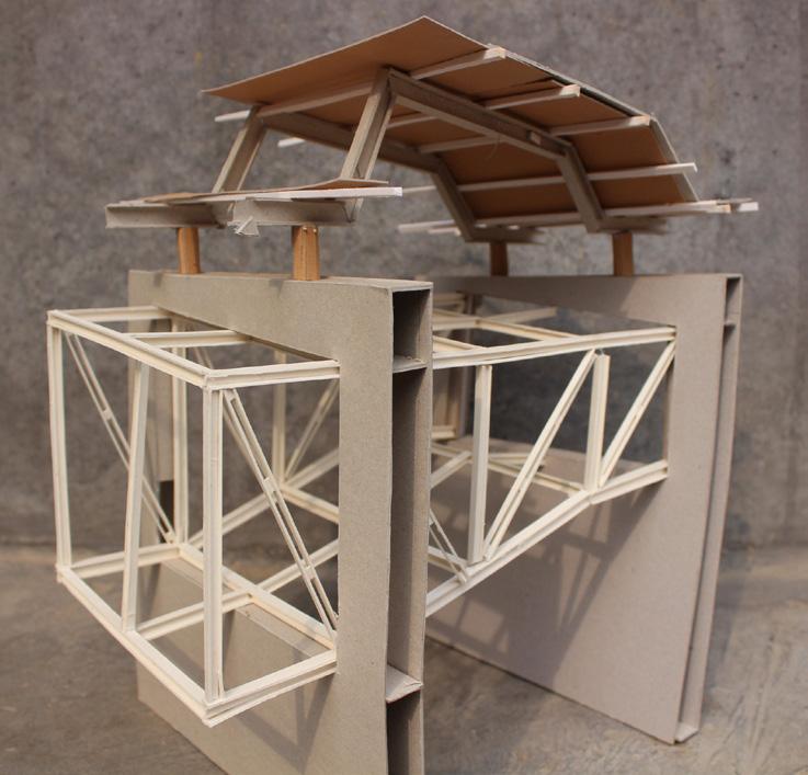
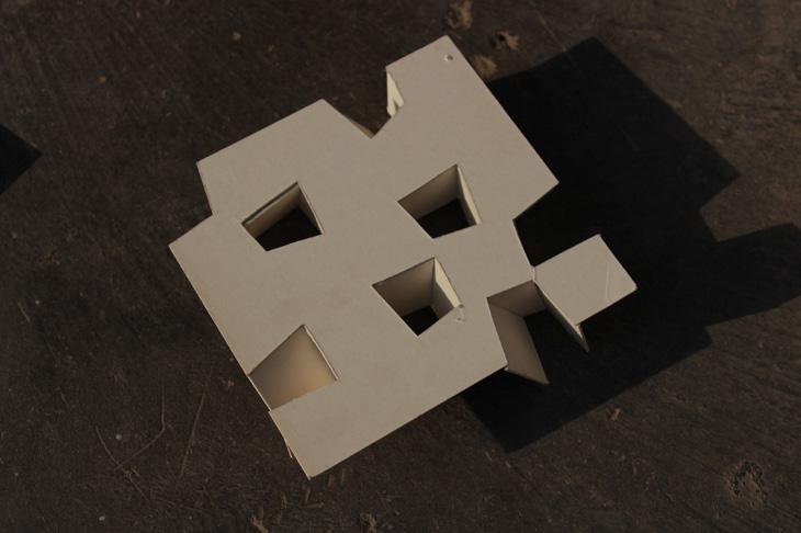
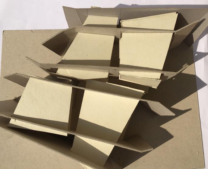
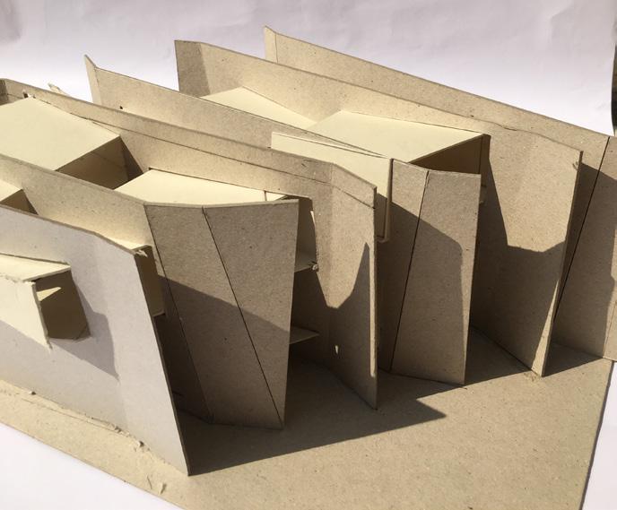
Designing a space for interpretation center for the archeological elements which are excaved from excavation site of Dholavira. The design process was derived through a matrix of form and structure considering the environmental factors such as view , light , air and wind , climate insulation.
71
Interpretation Center| Introduction
Interpretation Center
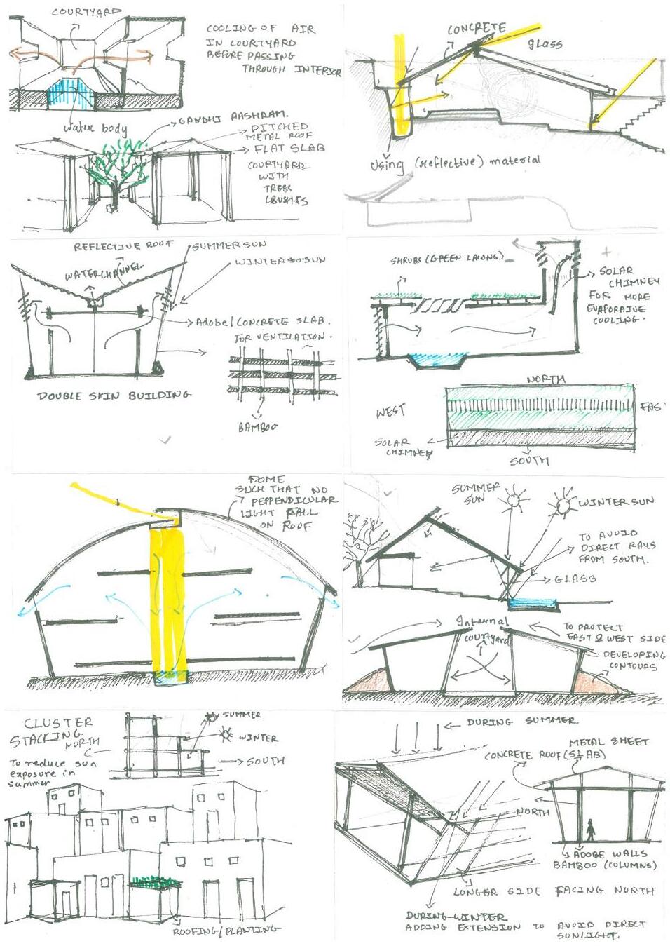
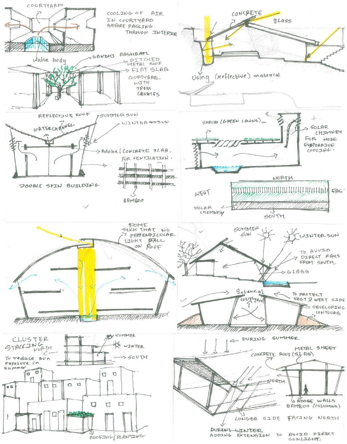
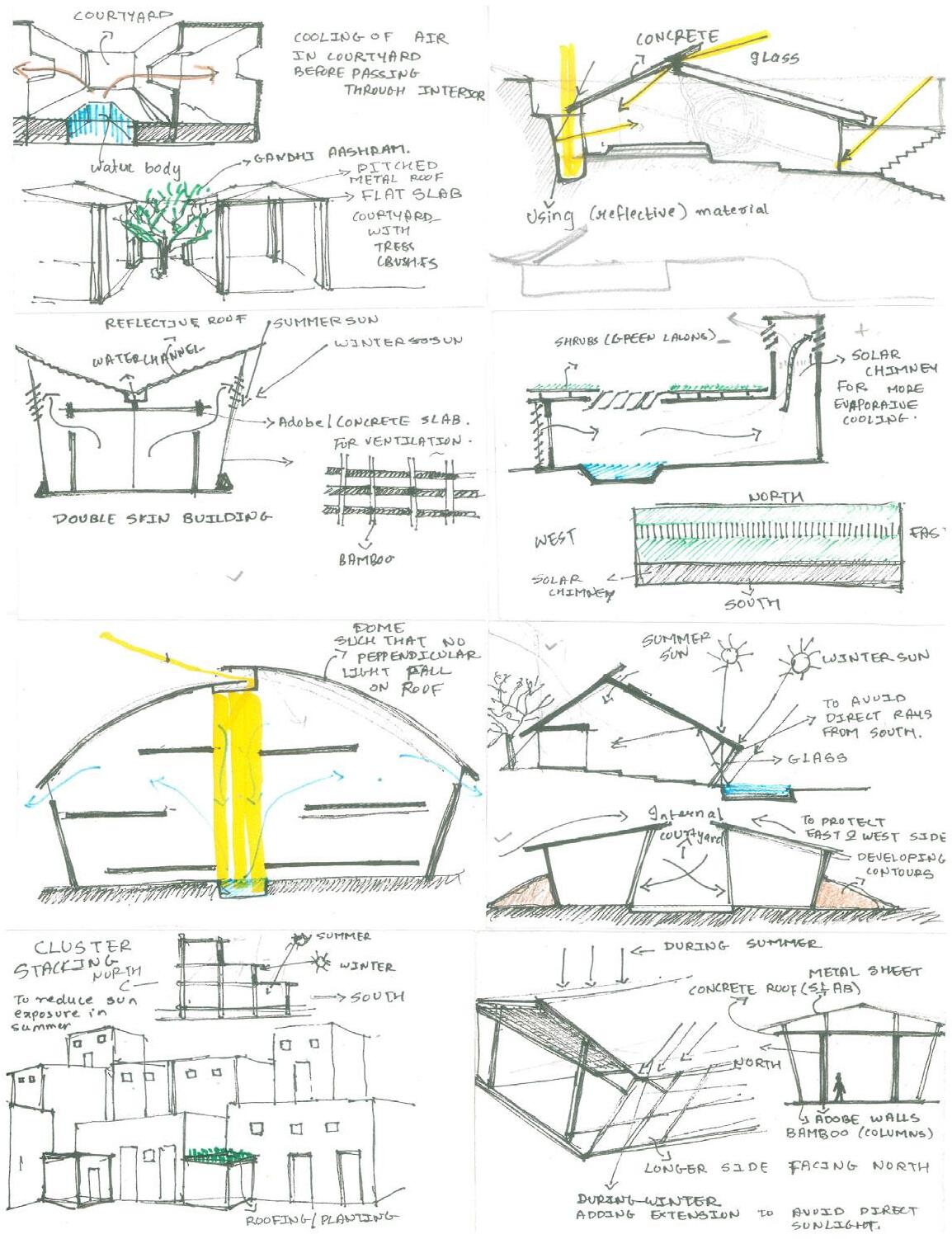
Matrix Diagrams for site with respect to light, wind, sun and view factor
INFERENCES

72 L W
HARIPRIYA PATEL UI1015 LIGHT WIND SUN VIEW


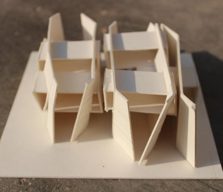


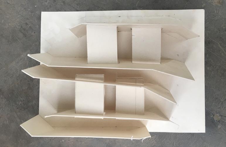
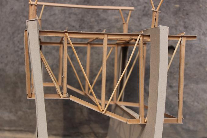
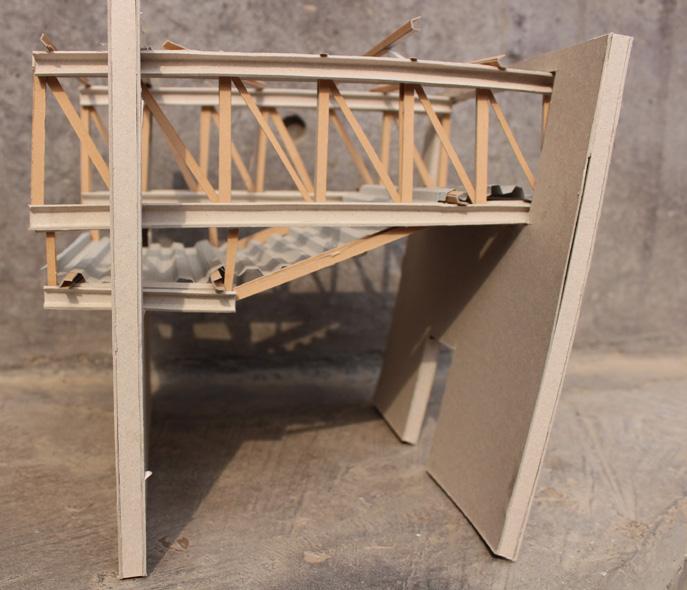
CONCEPT MODELS for Form Development
73 Interpretation Center
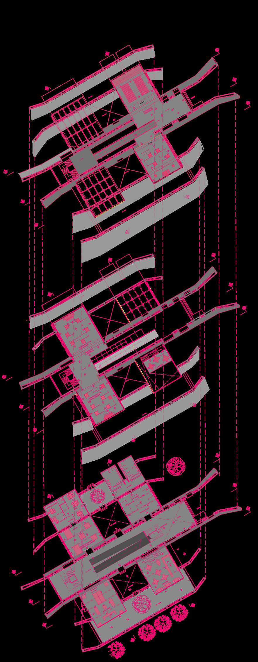
Exploded axonometric showing space planning
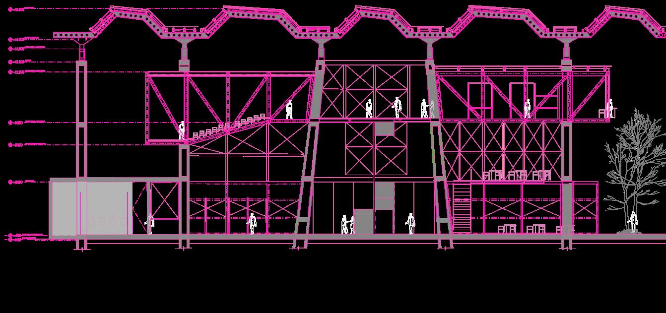
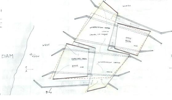
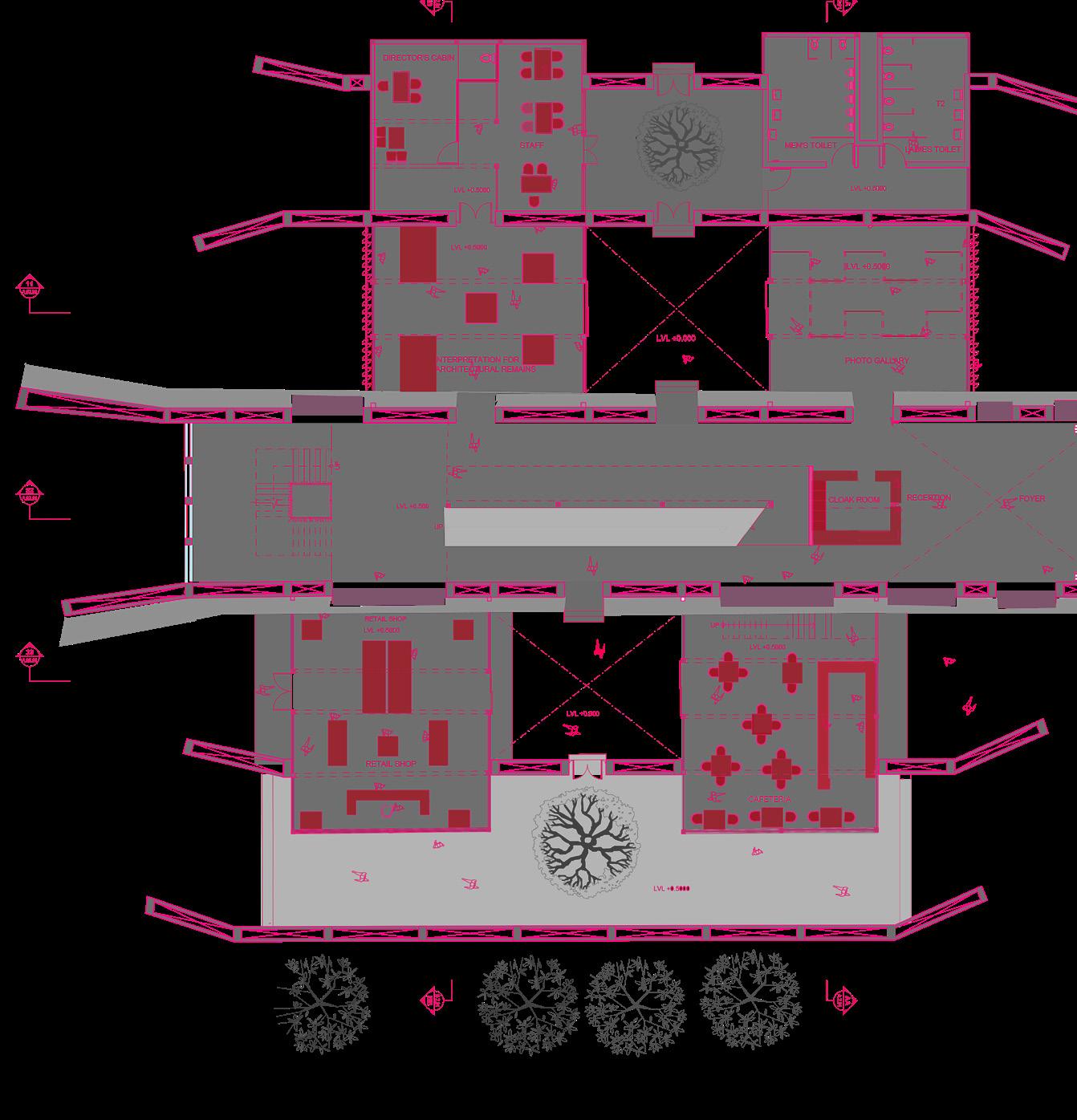
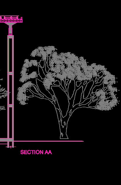
Section AA showing the space planning of the 5 bays central bay is circulation bay with with elevators. Right corner of the bay is the passage way towards shop and cafe. service with directors’ cabin, staff, and public toilets. 2nd and 4th bay (from the left) centre, auditorium, photo gallery.
74
1 Photogallery 2 Interpretation for Architectural elements 3 Cafe 4 Souvenier Shop 5 Director’s Cabin 6 Staff Area 7 Reception 8 Cloak room 3 Cafe 9 Clay Interpretation 10 Ceramics Interpretation 11 Auditorium 12 Metal Interpretation LVL. +2.50 m LVL. +6.00 m LVL. +7.50 m 8 7 5 6 4 3 2 1
Interpretation Center
SECTION AA
with ramps, and staircase
Left corner bay is the is the main interpretation

GROUND FLOOR PLAN

SECTION BB
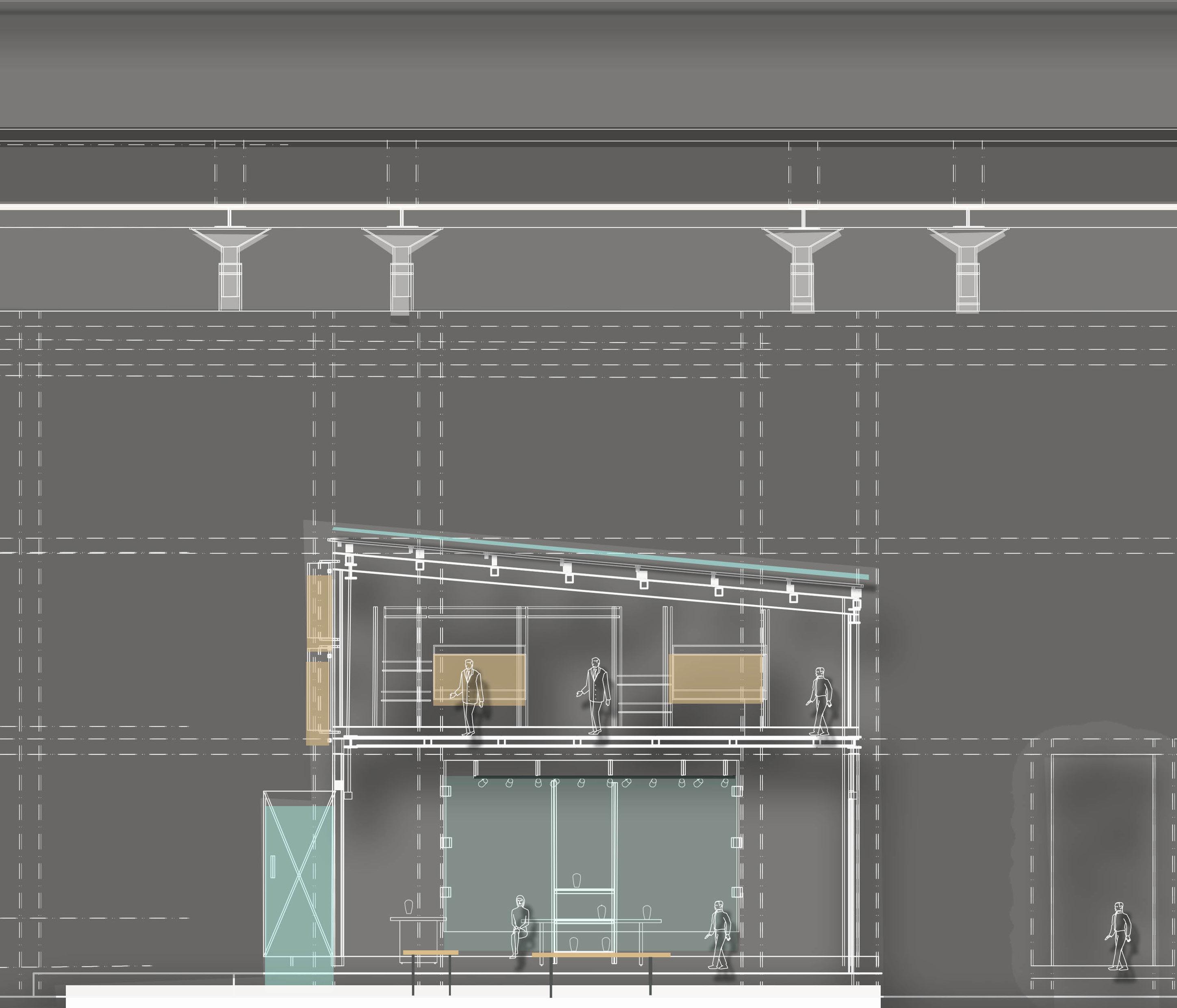
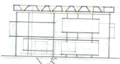
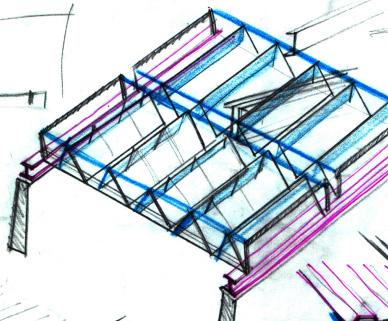
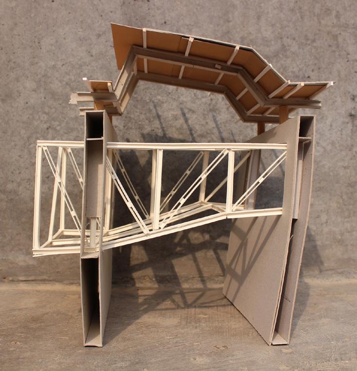
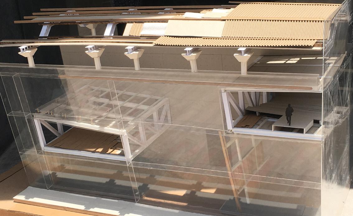
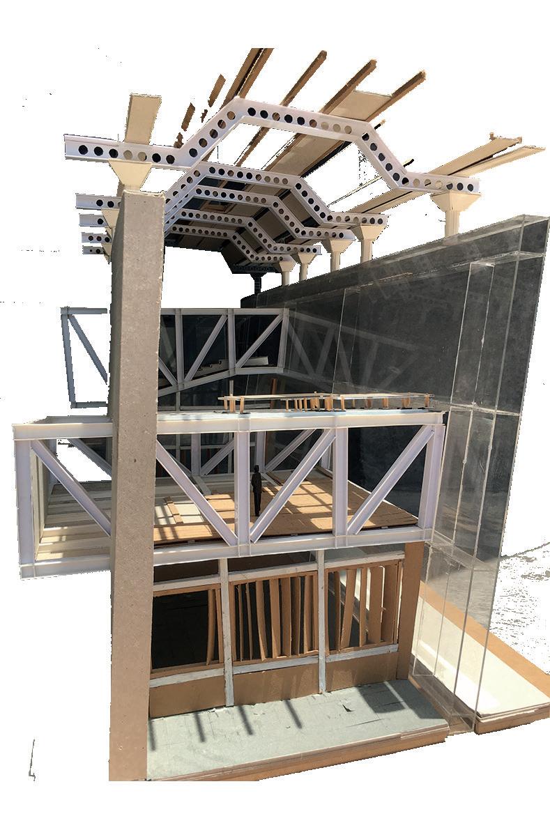
Section BB showing the insertion of truss modules in between the concrete cavity walls. Inserted Truss modules are glazed with Louvers on the facade to allow the flow of air from west- east direction. The casteleted beam truss houses the louvers in the north direction to allow light inside the space.

SECTION 33
Section 33 showing the space divides in 3 halves in which the central space behaves as module for wind /air circulation levels in the other two modules helps in the clear view even from the other half of the building. Lower spaces are the public spaces (cafe, shop )which are easily accessible rather than the upper levels which are interpretation centre which needs to be more connected with the site visually.

SECTION 22
Section 22 cutting through the Ramp which is the connecting element for all the modules of truss which are staggered , scale and nested within the vertical walls along east-west direction.
75
Center
Interpretation
LVL. +2.50 m
Interpretation Center
Wall Section showing the joinery detils and the Material Specification of metall truss module and Concrete cavity walls
76
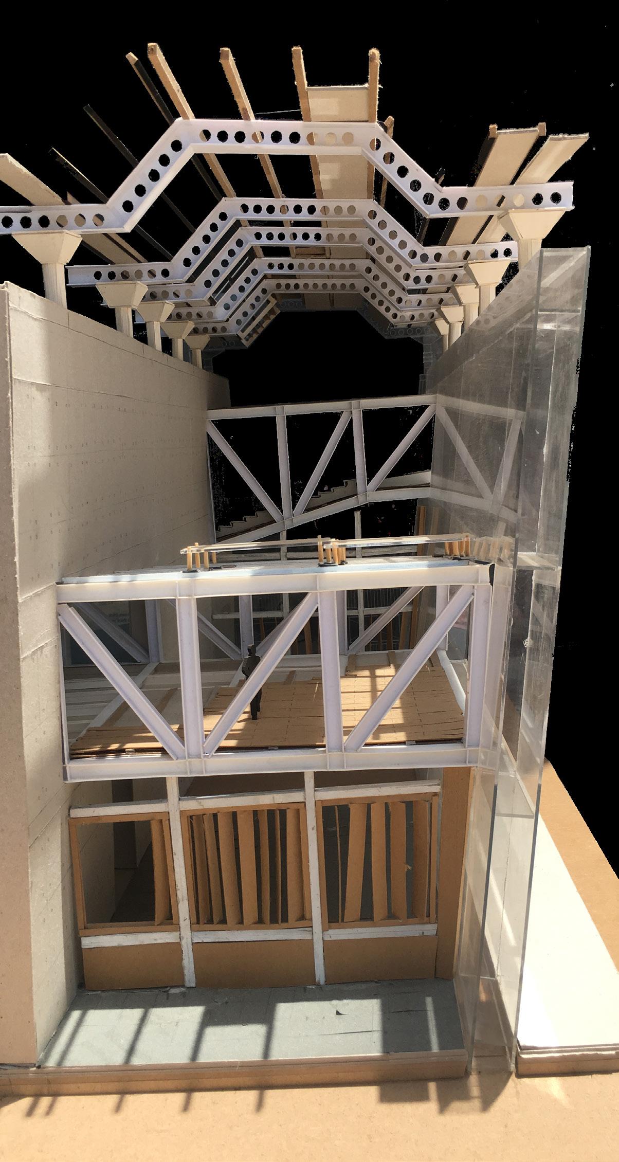
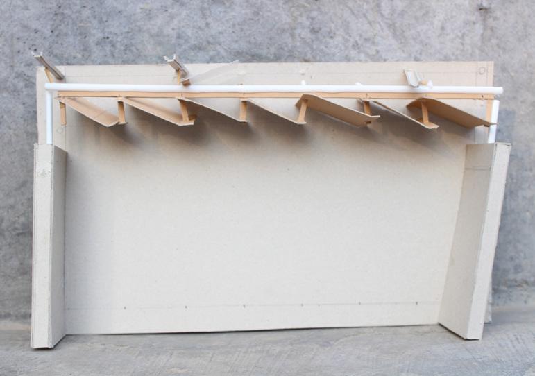
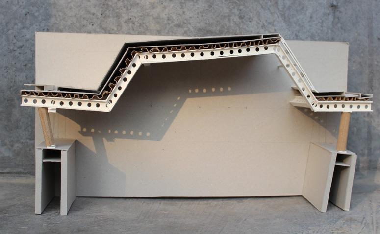
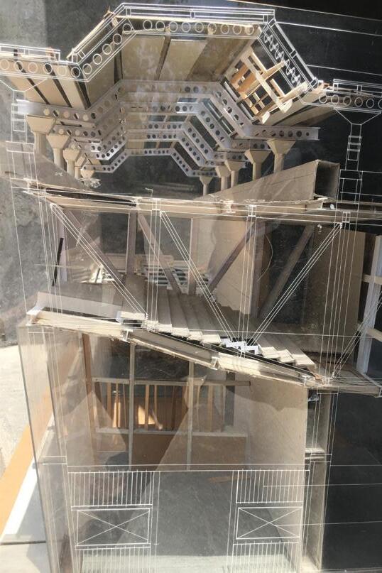
Sectional Model
Model showing how bridges made up of truss are inserted within two solid free standing concrete walls and floating roof helping wind and light to penetrate through the exhibition center without harming the content of the display.
Thus forming a space in a space with inner space with exhibition system which is a transparent cube inserted within a big rectalgular volume of space with Insulated roof and walls. Size : 1.2m x
77 Interpretation Center
0.6 m Scale : 1:25
Wood and Metal | Introduction
Furniture:
Miscelleneous 08
Hands on Making
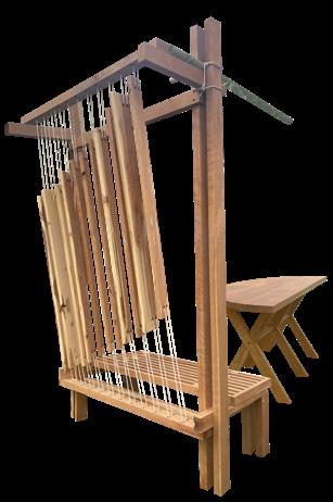
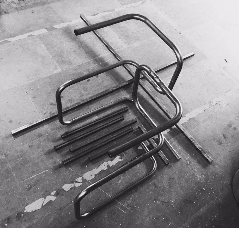
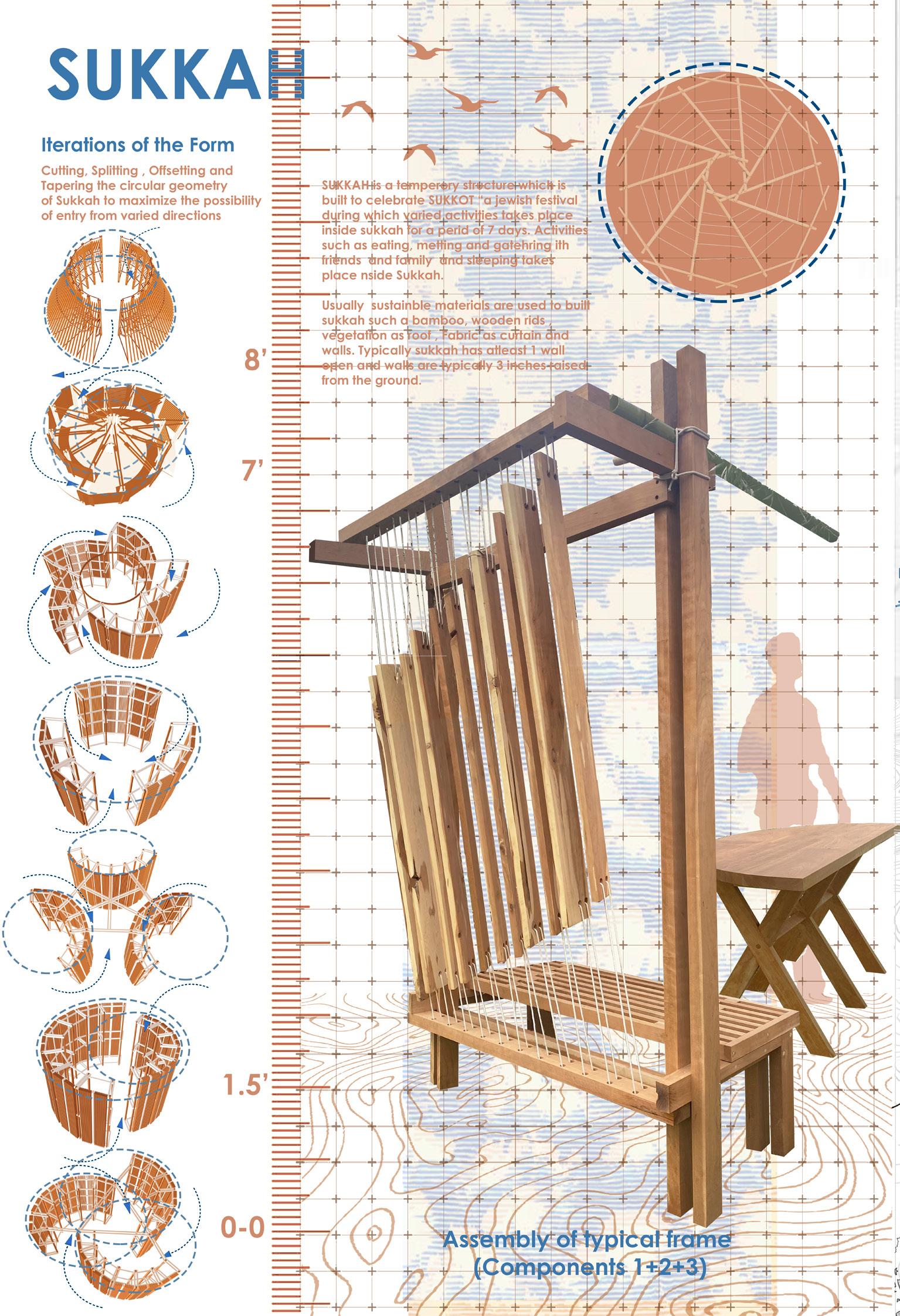
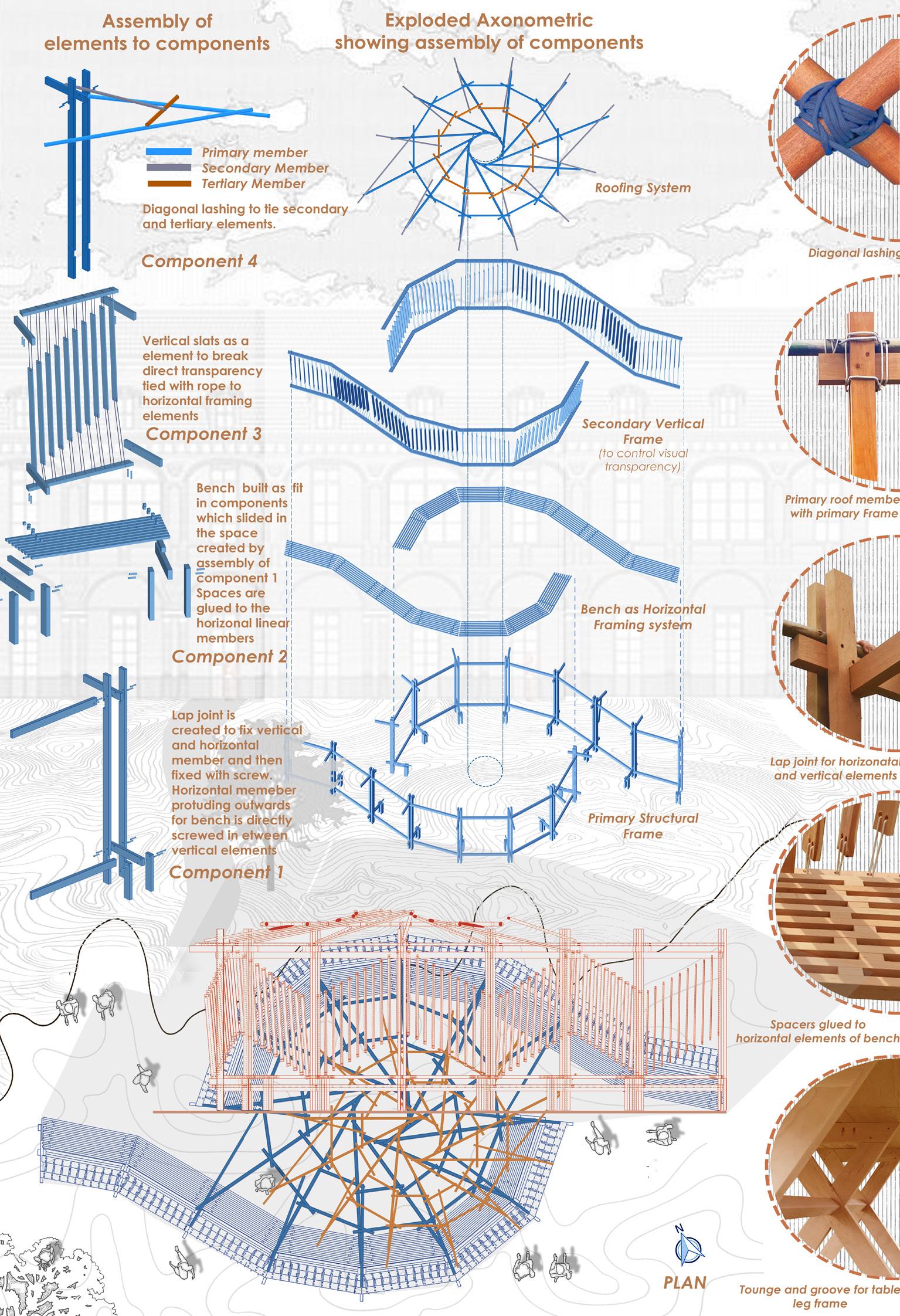
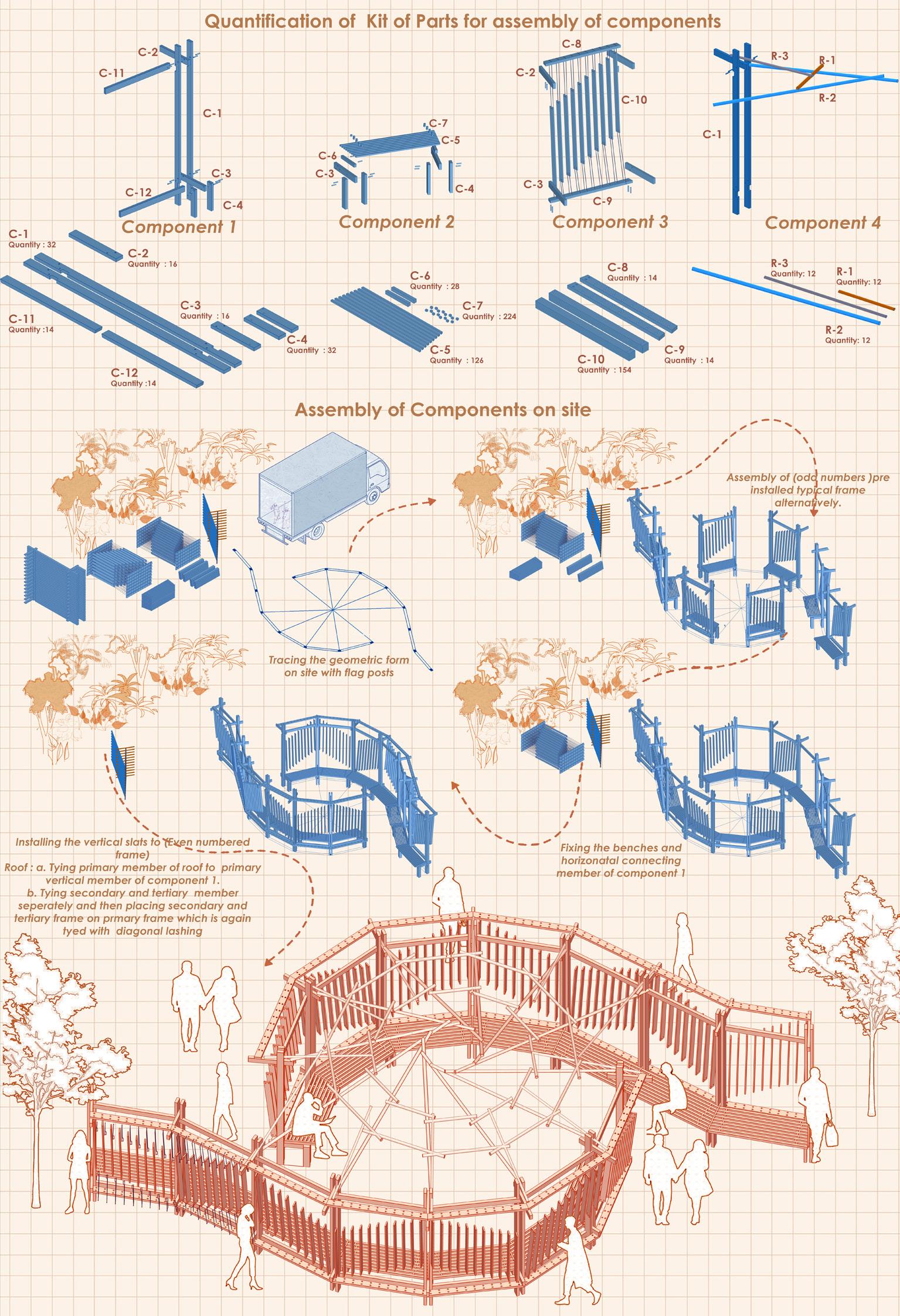
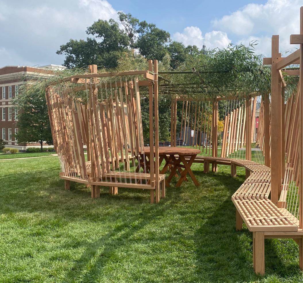
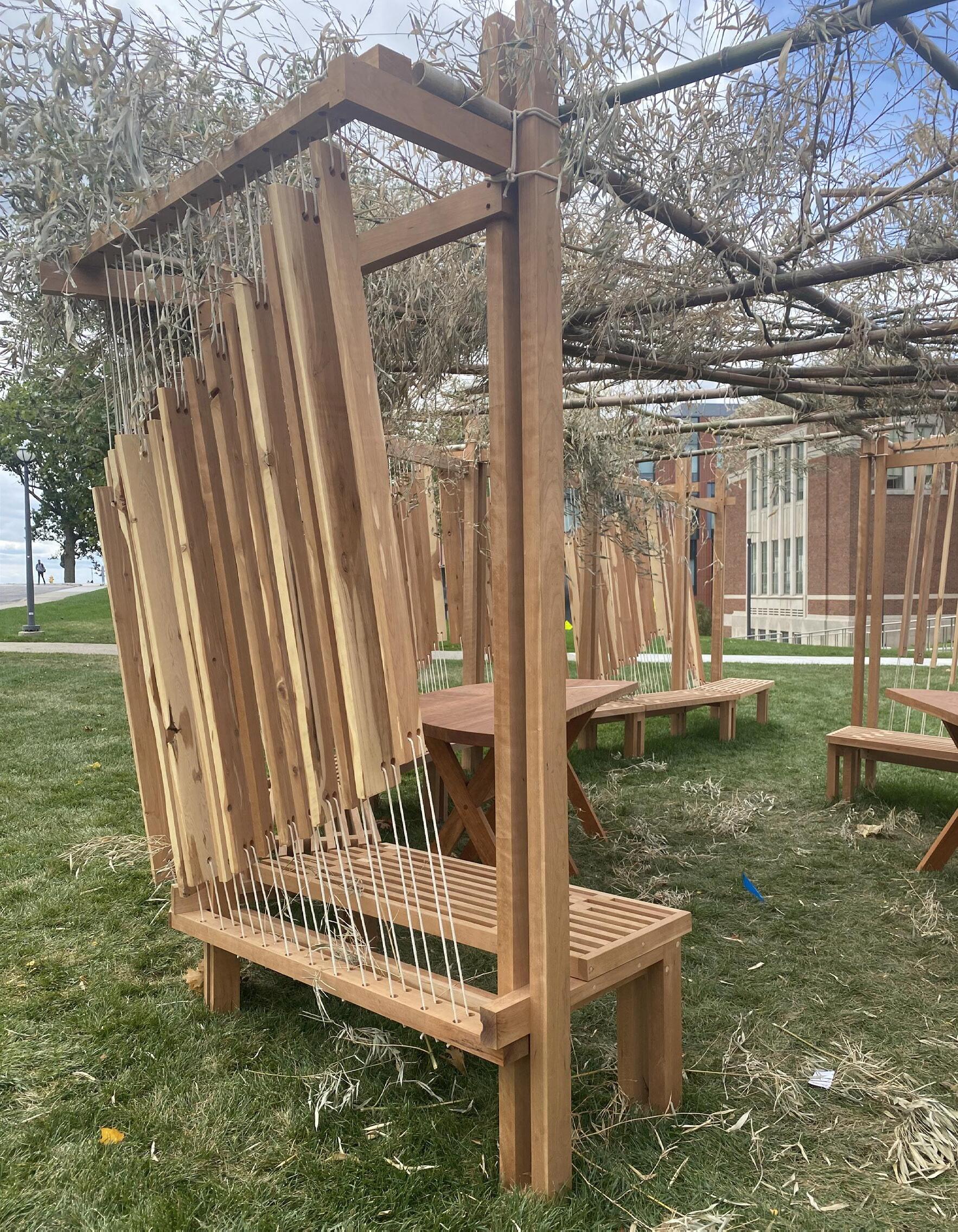
Experimenting with crafting wooden and metal furniture, incorporating a bamboo deck, and assembling a wooden sukkah presents an exciting opportunity to explore various materials and techniques. Additionally, the inclusion of glazed ceramics, red clay, acrylic lamps, and tie-dyeing methods further enriches the creative process, allowing for the fusion of different textures, colors, and forms. This interdisciplinary approach encourages the development of innovative and eclectic designs that are both aesthetically pleasing and functional.
Furniture: Wood and Metal | Introduction
 Furniture: Wood and Metal
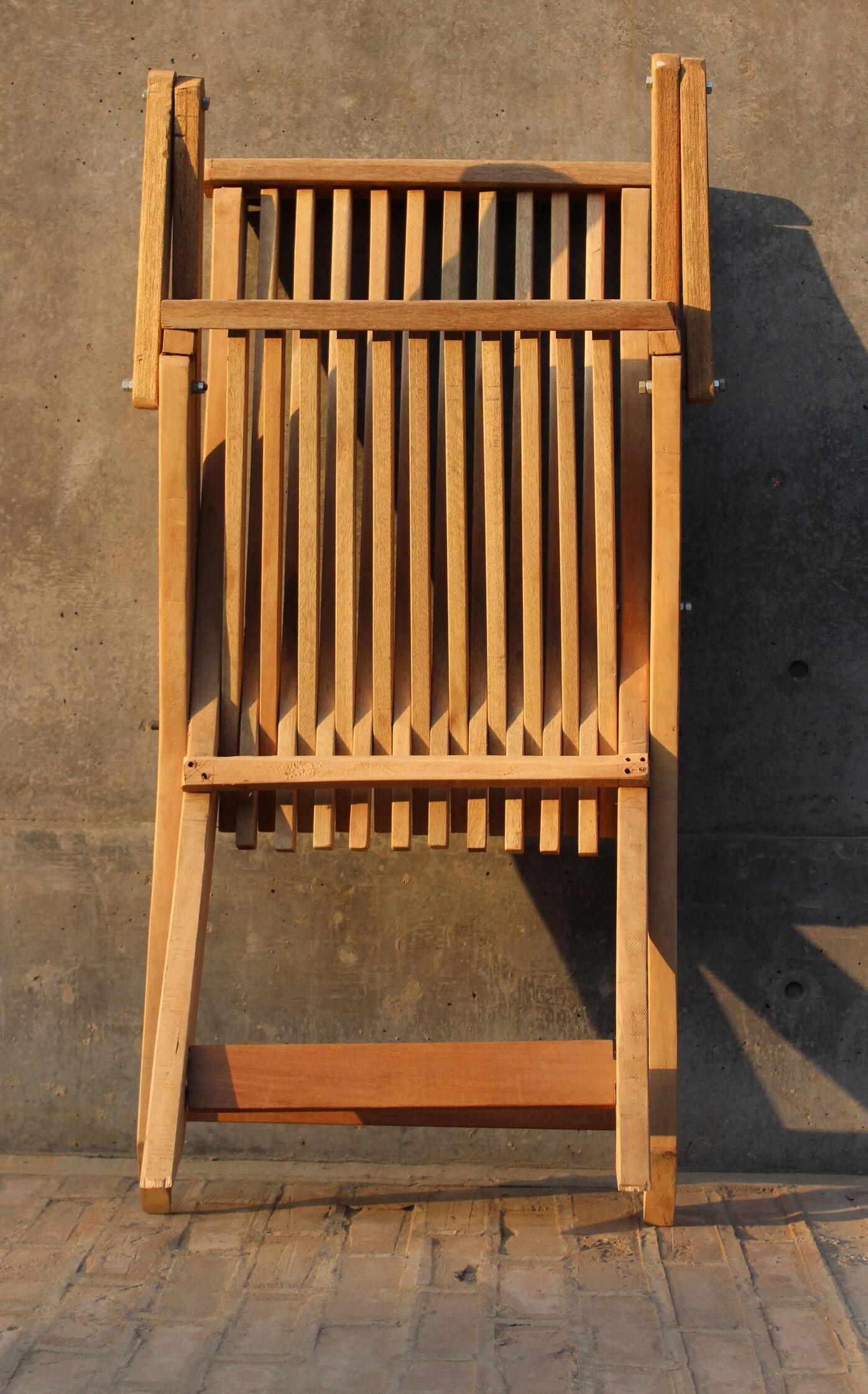
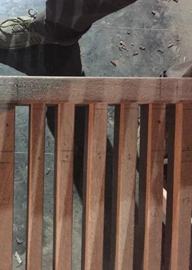
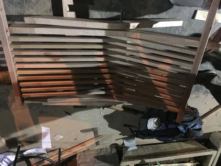
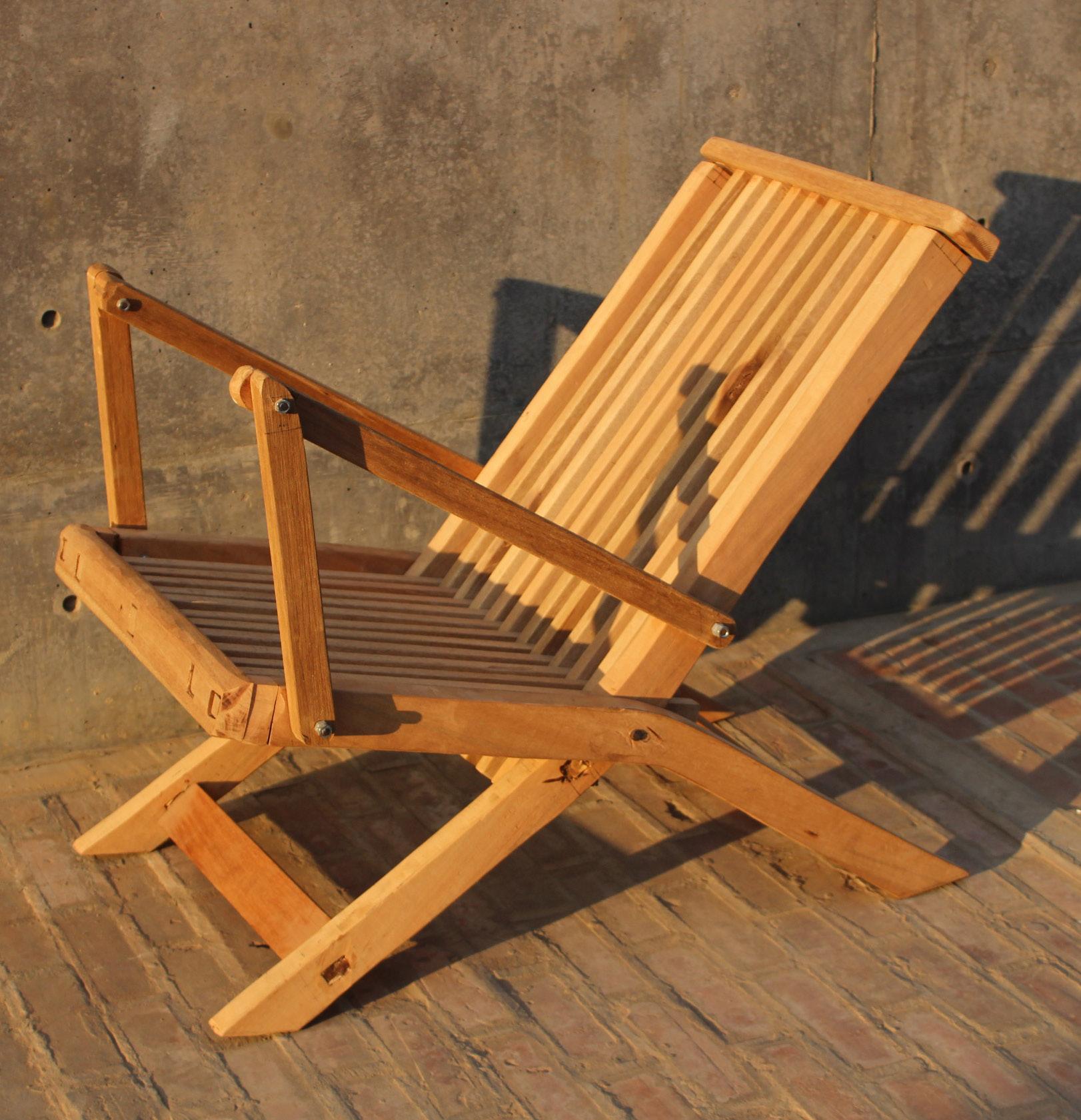
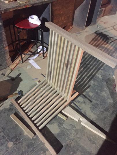
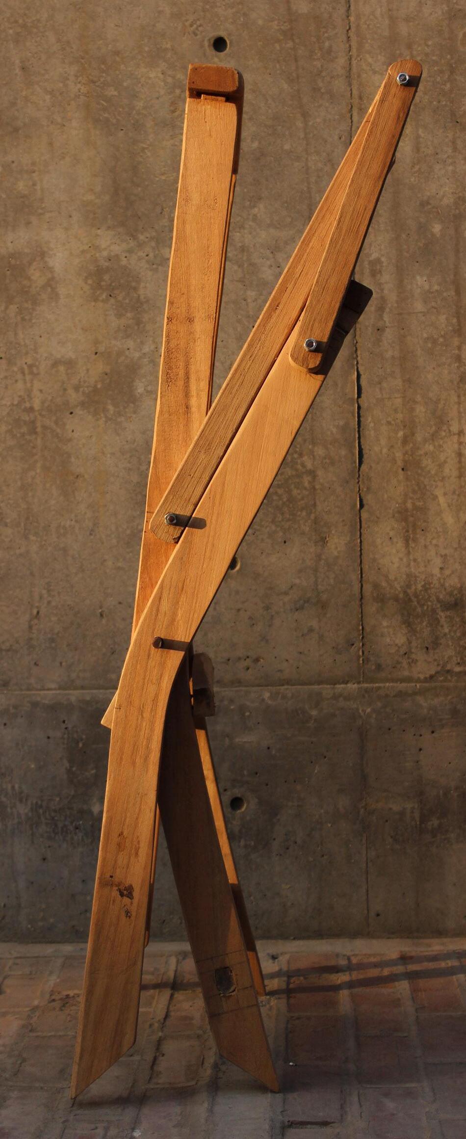
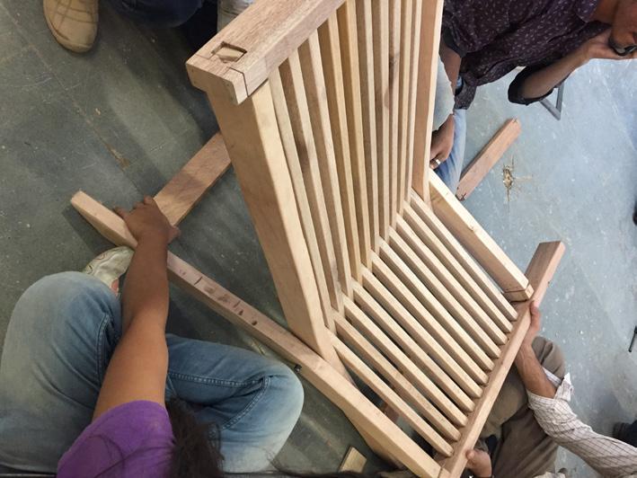
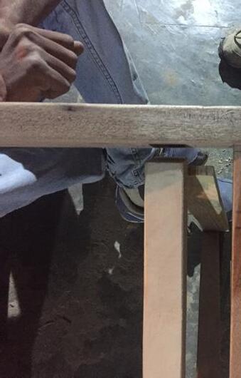
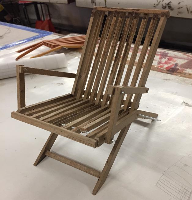
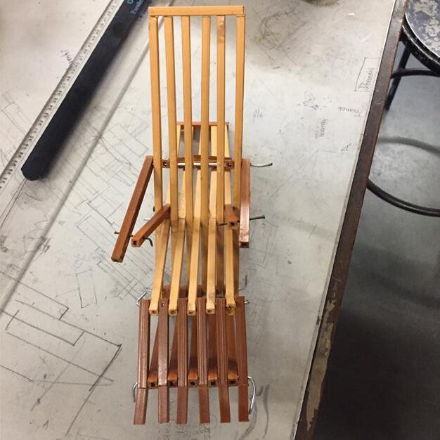
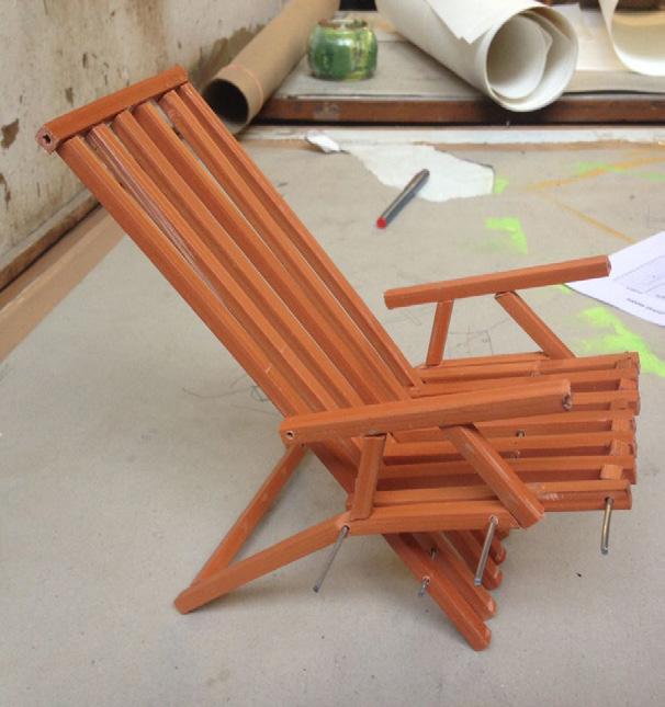
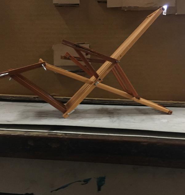
Wooden Folding Chair (Prototype)
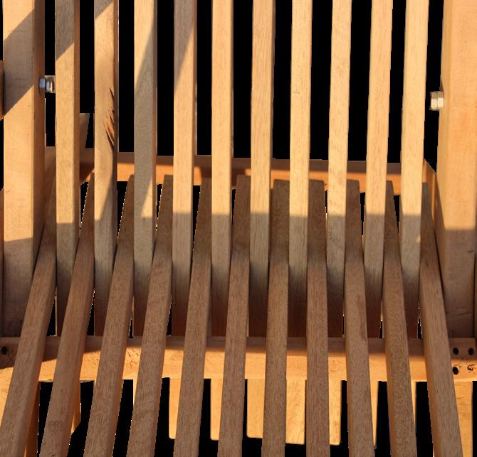
This folding chair is designed for Sitting and Watching T.V. for a space designed by Frank Lloyd Wright (Robie house). The furniture designed reflects the ideology of linear vertical members along with horizontality which is reflected in the spaces designed by the architect.
Role : Concept and Design of the Furniture.
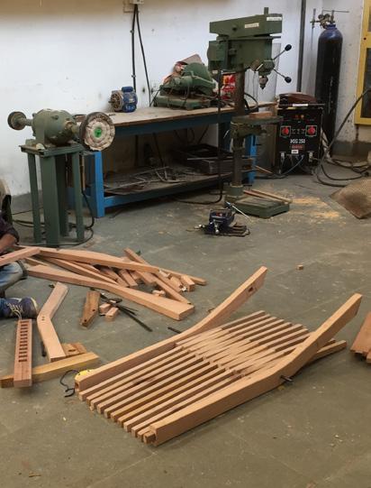
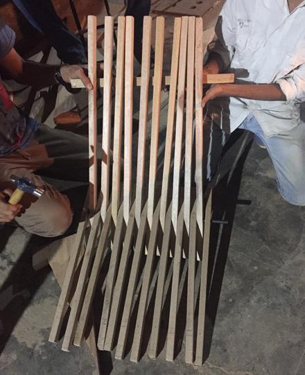
Prototype: Execution was done in a gorup of 4 people.
 Furniture: Wood and Metal
82 Working with Bamboo|Deck
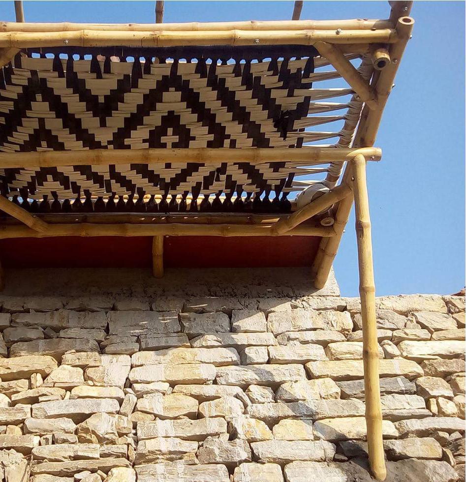

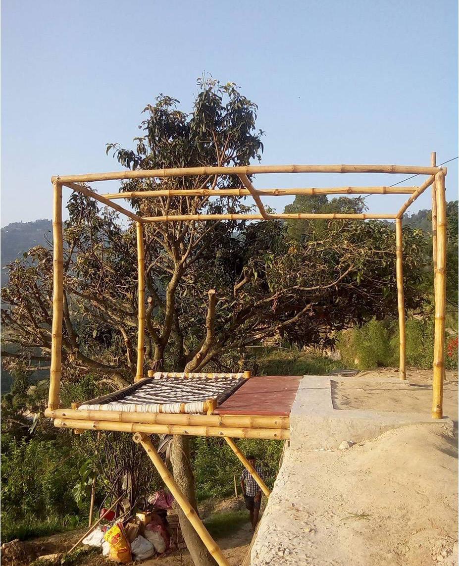
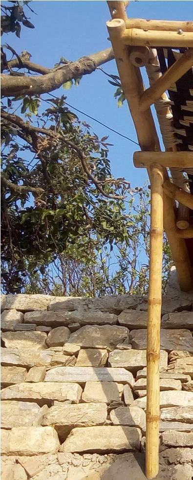
Cantilever Bamboo Deck
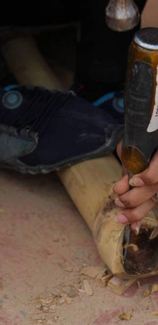
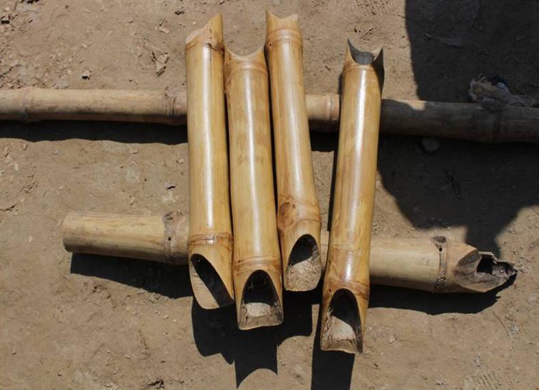
The Building of small bamboo deck / pavilion space to scale so as to explore the various stages and structural aspects of this style of construction.
The learnings during the project included the study of the inherent properties of bamboo and it’s use in structural design during their site visits to ABARI projects but also were keen to train in making our joining mechanisms.
Step 01
Preparing foundation pit for the cantilever deck with column on both side with a connecting beam .
Digging a pit and then first filling up with stones and then ramming it so that the earth stays at a place and gives a plain clean surface for frame work to rest and concrete to be poured.
Step 02
Selecting bamboo and processing it. For structural use bamboo should always be selected from the shorter side i.e from the side where there is lesser distance between two nodes. Then sanding the nodes and making it smooth for aesthetics and also to avoid wear and tear.
Applying varnish on bamboo for aesthetics and to protect it from rain, sun, wind etc.
Step 03
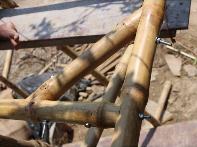
Making fish mouth joinery in bamboo and fixing it with barrel nut and threaded rod.Horizontal 45 degree bracing drilling on site while assembling and tying it with threaded rod and nut. Fixing bamboo with threaded rod while rotating it which was inserted in concrete beam.Fixing and tighting nut with key.
Working with Bamboo|Deck


84 Ancillary| Exploring Materials
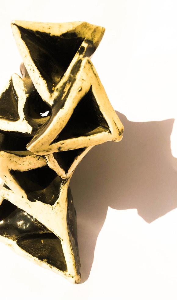
Ceramics and Glazing
Ceramics and Glazing
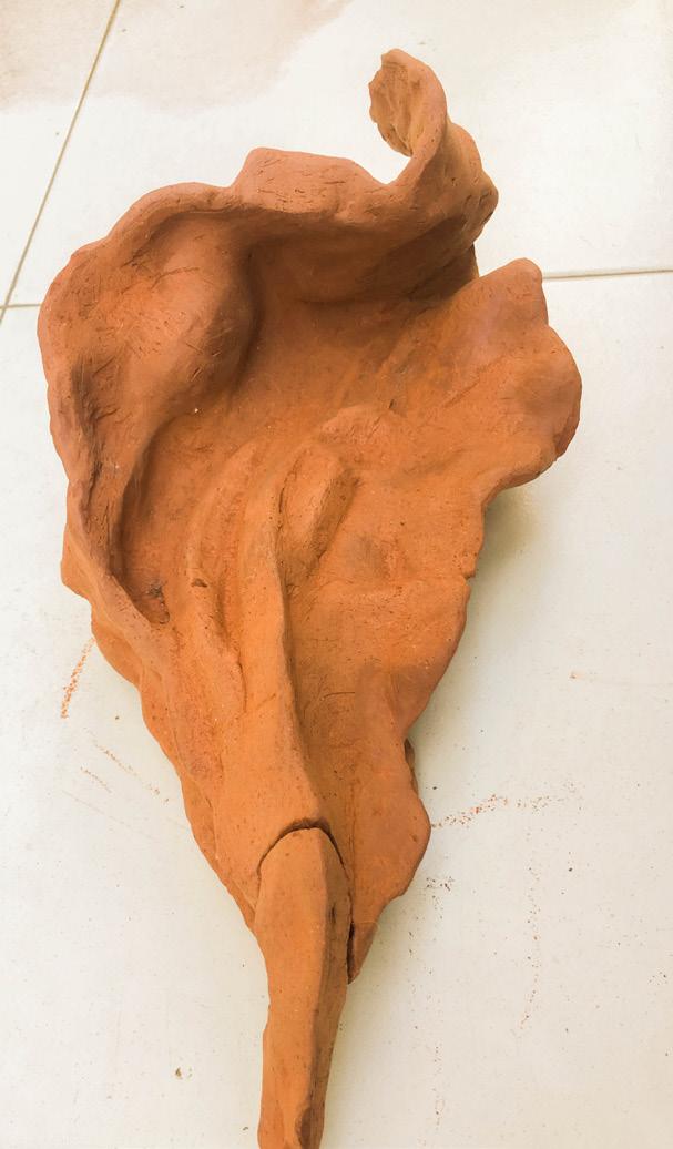
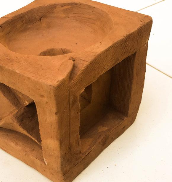
Red Clay Form
Red Clay Form
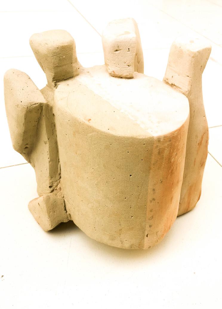
Plaster of Paris Form
Ceramics
Exploring Materials:
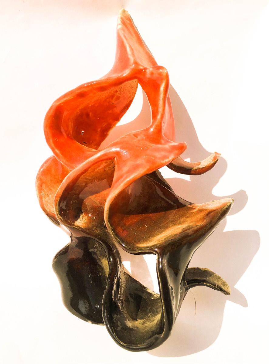
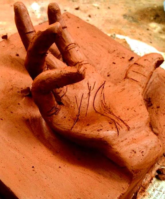
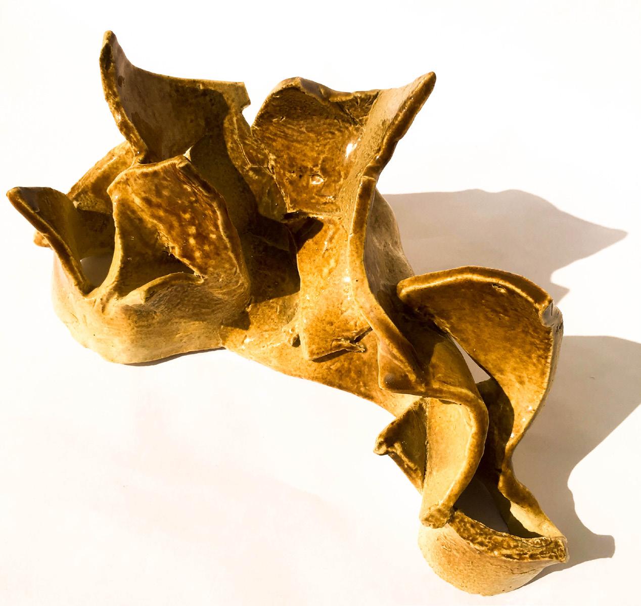
Clay,Ceramics and Acrylic
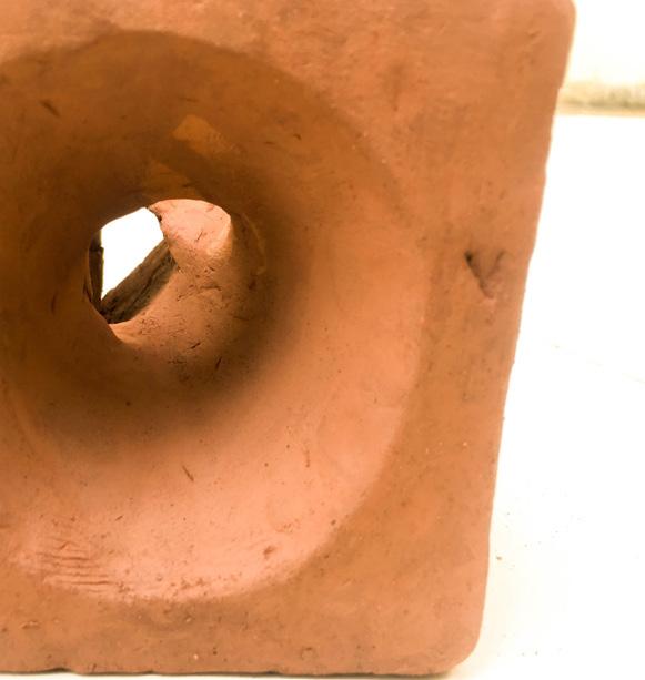
Red clay : making forms of leaf, hand with position, carving out space from a cube .
Ceramic: Developing forms inspired from Warli art. The black and white element assembled out of triangles.Techniques adn types of spray glazing with double coloue were experimented.
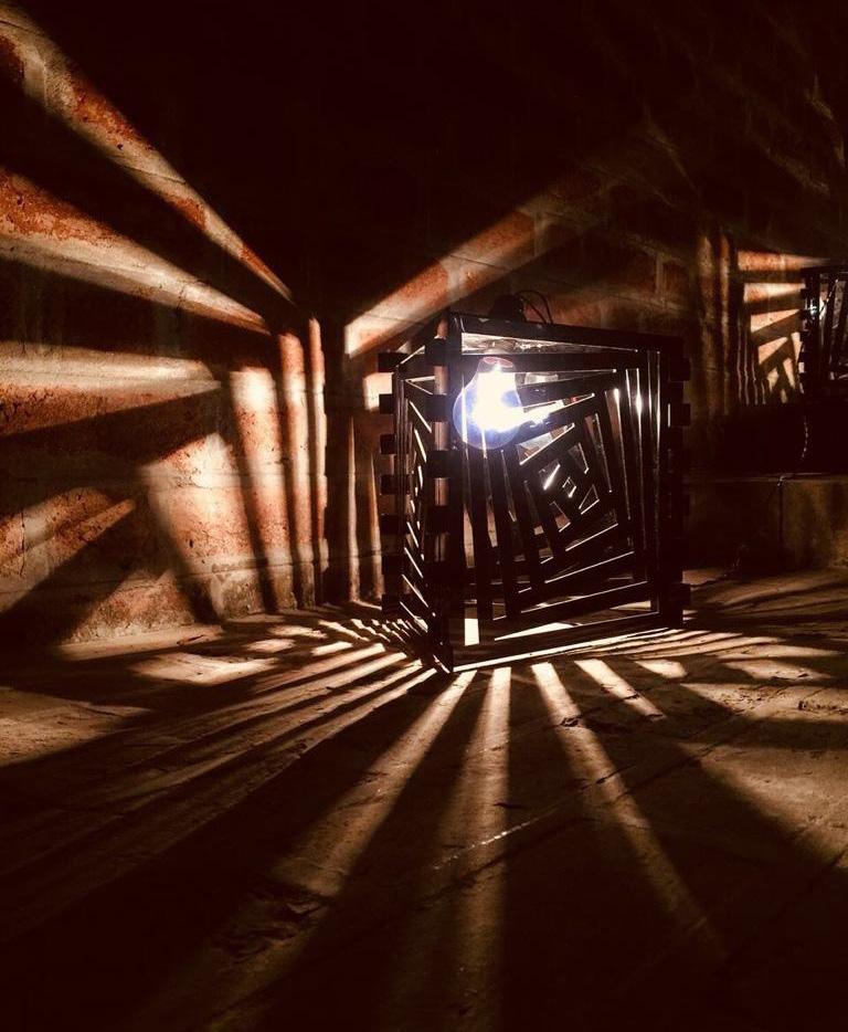
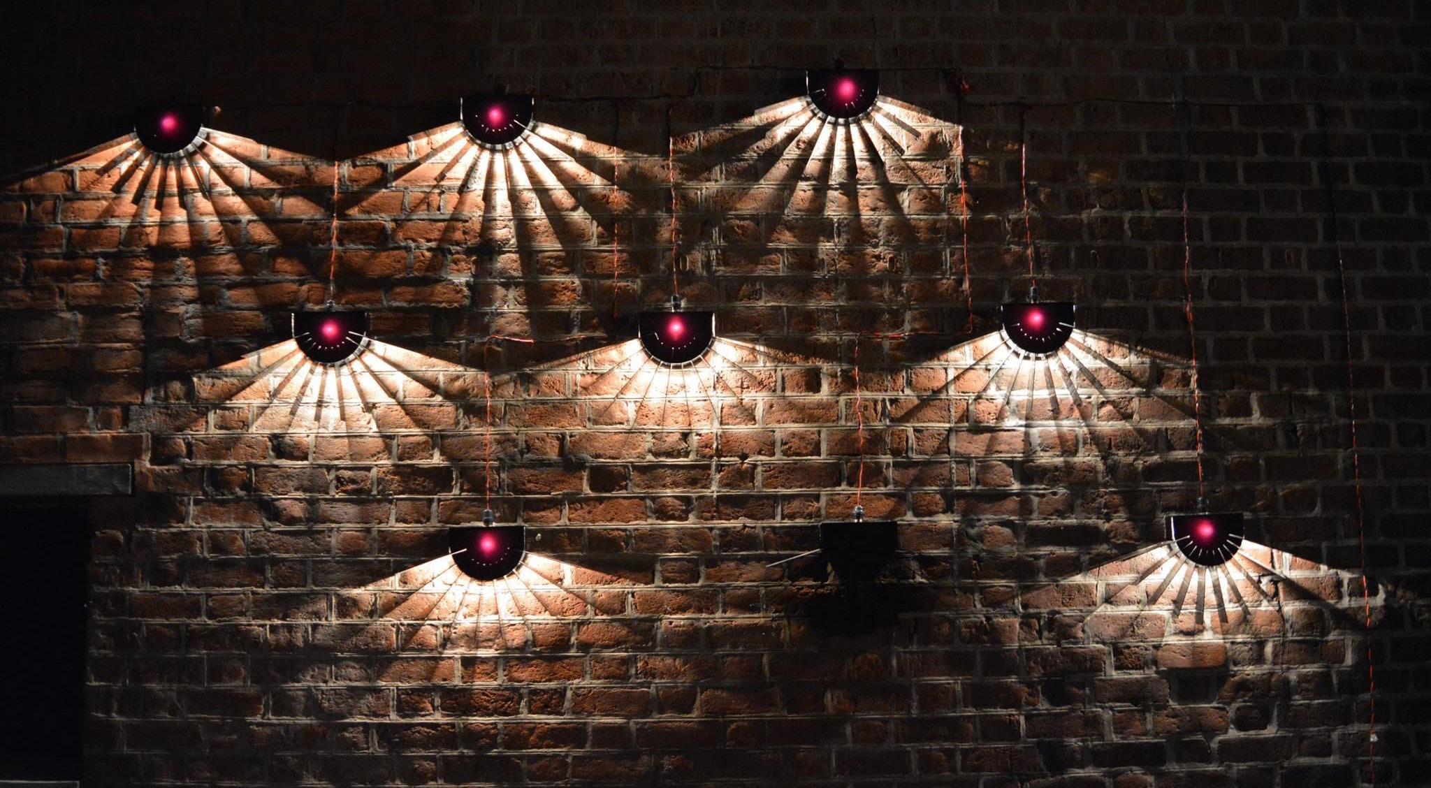
Acrylic : making lamps for Navaratri made out of black opaque acrylic lazrcut sheets. (9 day festival in gujarat) (group of 4)
85 Ancillary| Exploring Materials
Ceramics and Glazing
Red Clay Form
Working with wood|Sukkah
86

87
Working with wood|Sukkah
88
Working with wood|Sukkah

89
Working with wood|Sukkah
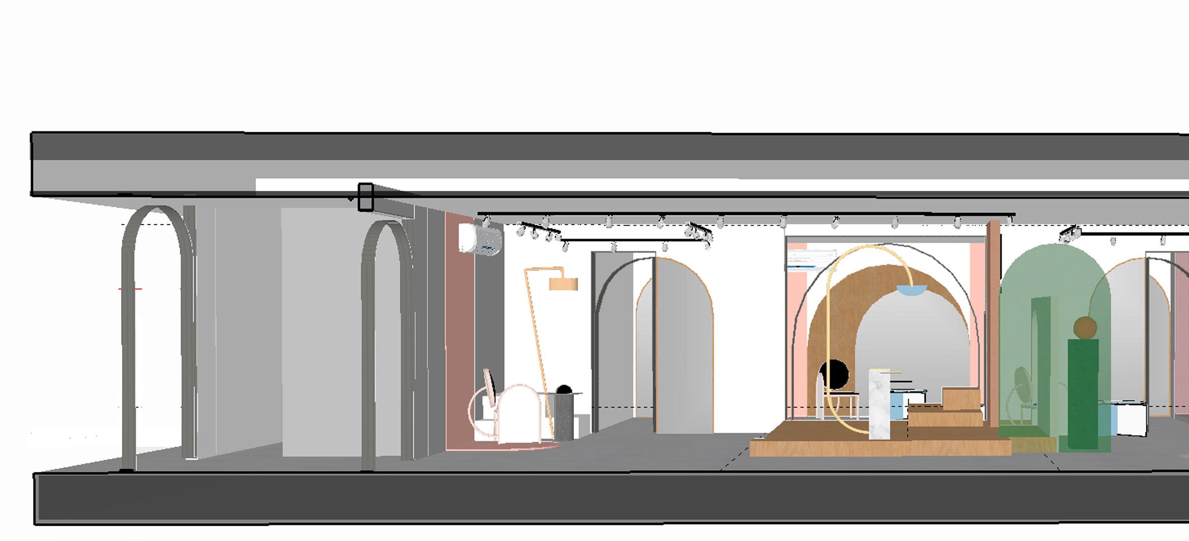

90 Arisaa by Projects 3.14
Brand Wall Concepts
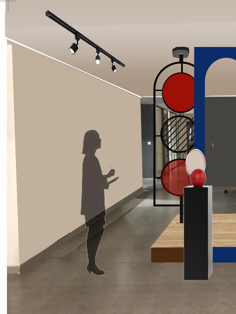
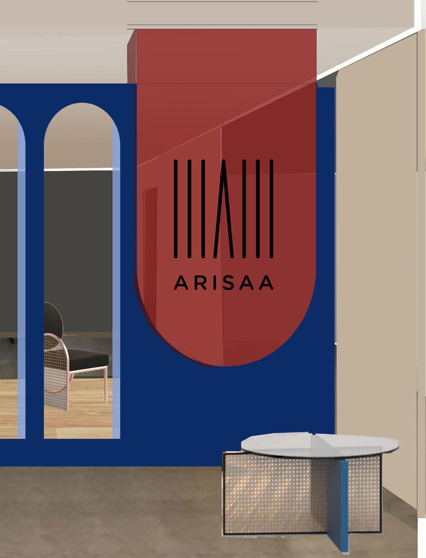
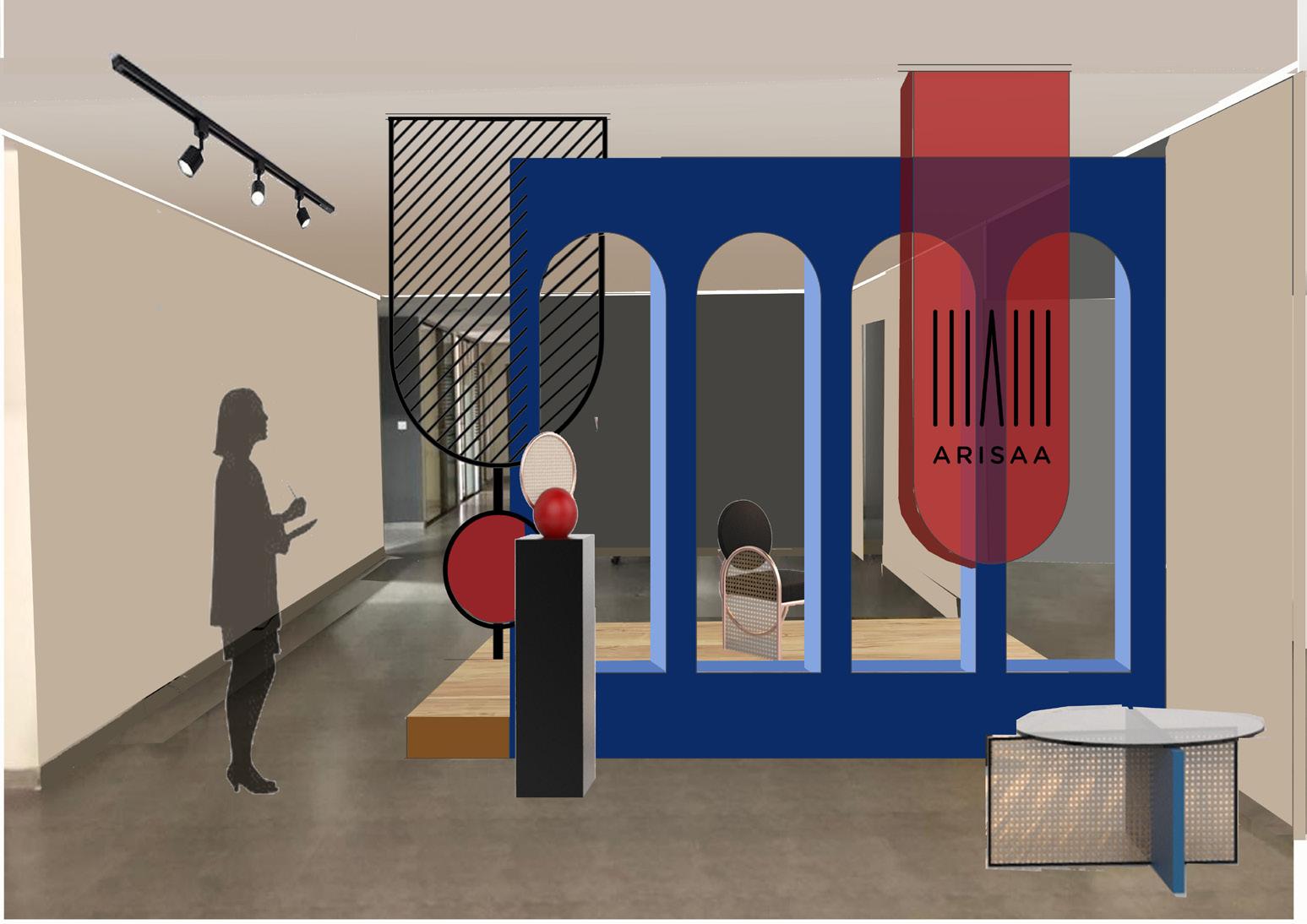
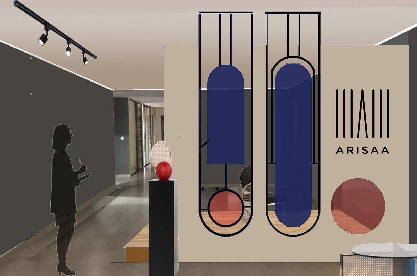
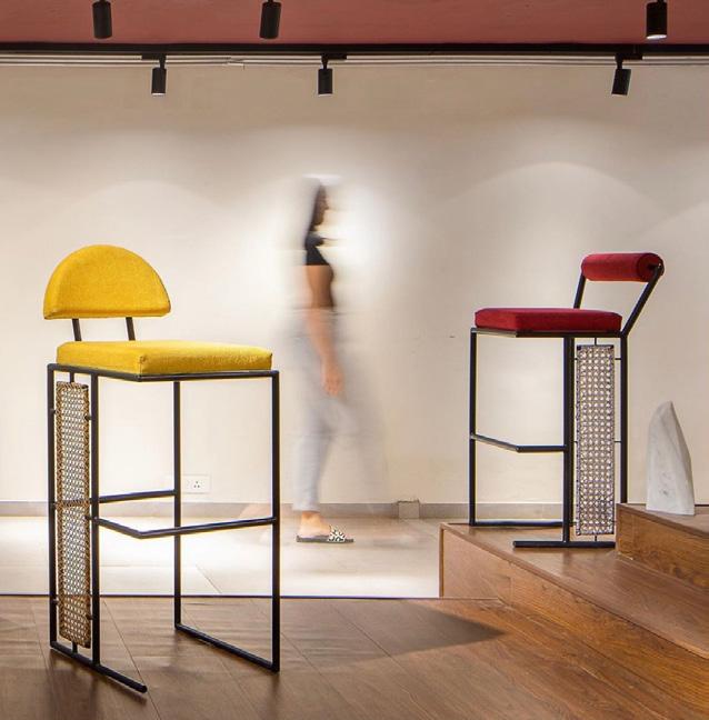
The brand concept is developed by taking the inferences from the expressions ,language, style, material, form and colour of the Furnitures and inteior elements designed by brand Arisaa.
Toning down the background shades such that the brand wall is highlighed through the dark blink red and blue color.
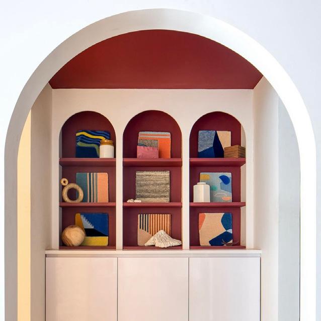
Arch shape infered from the forms and the shape of the furniture. Black powder coated metal frame complimenting the sleekness also presented in the furniture elements.
91 Arisaa by Projects 3.14
Conceptualization
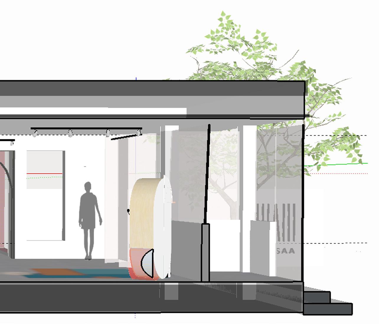
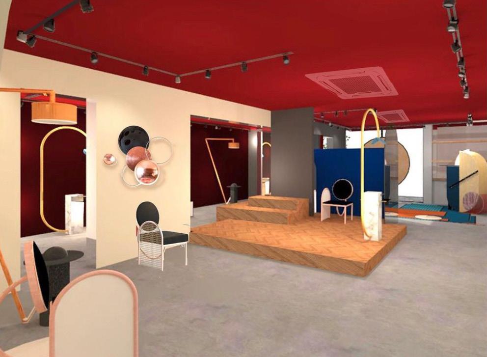
The design of the products played an important role while conceptualizing the space.
The pop colours in the furnitures drived the idea to keep the background plain and add a bright touch of colour to the ceiling which will also play a role of binding element to unify and enlarge the whole space visually.
The central stage is to display the new upcomming exclusive range of furniture
92 Arisaa by Projects 3.14

93 Arisaa by Projects 3.14
94 750 621 1045 1045 2090 1371 100 B B' D D' C' C A A' PLAN eq eq eq eq eq eq eq 2175 SECTION B SECTION C SECTION D eq 615 165 450 1562 eq 2010 697 X 90 MM 2010 2010 X 686 MM 2010 x 586 MM 2010 X 621 MM 697 X 90 MM 697 X 90 MM A1 A2 A3 B1 B2 2100 X 730MM SLAB 5 GREY 2100 X 730MM SLAB 6 GREY 2100 X 730MM SLAB 7 GREY 1371 2090 2100 X 730MM SLAB 1 GREY 2010 X 522MM 2100 X 730MM SLAB 2 GREY 2100 X 730MM SLAB 3 GREY 2010 X 522MM 2010 X 522MM 2010 X 522MM 2100 X 730MM SLAB 4 GREY A4 A1 A2 A3 A4 B1 B2 D1 2100 SLAB GREY 485 485 83 83 45° 45° 83 83 485 485 167 167 45° 45° 167 167 b2 b1 d1 a a a a a a a a a a a a a 1 1 1 1 1 1 2 2 2 2 2 2 b b b b b b b b b b b b 3 3 3 3 3 3 4 4 4 4 4 4 a a a 2 2 2 2 2 2 1 1 1 1 1 1 1 4 485 485 167 167 45° 45° 167 167 3 485 485 83 45° 45° 83 83 2 83 b2 b1 a1 a2 a3 a4 c1 c2 c3 c4 c1 c2 c3 c4 B3 B3 522 522 x 522 522 x 165 MM 686 x 165 MM 586 x 165 MM 621 x 165 MM 2010 x 100 MM 523 523 523 522 e.q. e.q. 2090 e.q. e.q. 1045 1045 165 165 MLK Office by Projects 3.14
95 SECTION A 165 2175 2415 621 D1 X 730MM SLAB 8 GREY 1635 X 1000MM SLAB 1 BLACK 485 343 343 45° 45° 90° 2010 a1 a2 a3 a4 a a a a a a a a a b b b b b b b b b b b b 3 3 3 3 3 3 4 4 4 4 4 4 a AND b d1 c1 c2 c3 165 MM 165 MM 165 MM 522 x 165 MM 522 x 165 MM 522 x 165 MM 522 x 165 MM 750 MLK Office by Projects 3.14
96 740 40 20 60 1020 920 40 245 40 350 40 245 40 220 40 880 40 880 40 220 1800 2400 212 8 11 220 200 115 118 457 200 122 193 175 350 740 1800 60 800 740 60 800 1020 2400 50 750 300 300 1800 A B
PLAN TABLE PEDESTEL PLAN A A B B SECTION A SECTION B ELEVATION A ELEVATION B 12MM WOODEN + 20MM 40MM +10MM 4MM THICK VEENER 20MM THICK PLYWOOD 20 40 40 245 40 40 270 40 40 245 40 1000 740 40 20 60 1020 920 40 245 40 350 40 245 40 220 40 880 40 880 40 220 1800 2400 212 8 11 220 200 115 118 457 200 122 193 350 740 1800 60 800 740 60 800 1020 2400 50 750 300 300 1800 A B TABLE
FRAME PLAN TABLE PEDESTEL PLAN A A B B SECTION A SECTION B ELEVATION A ELEVATION B 12MM WOODEN + 6MM 20MM 40MM +10MM 12MM PLY SANDWICH WOODEN BRACING+VEENER(VERTICAL + POLISH 20MM PLY +VEENER 40MM THICK +10MM THICK 4MM THICK VEENER 20MM THICK PLYWOOD 20 40 40 245 40 40 270 40 40 245 40 1000 220 40 880 40 880 40 220 1800 2400 212 8 11 220 200 115 118 457 200 122 193 175 350 740 1800 60 800 740 60 800 1020 2400 50 750 300 300 1800 A B FRAME PLAN PEDESTEL PLAN A B B SECTION B ELEVATION A ELEVATION B 12MM PLY SANDWICH WITH 16MM WOODEN BRACING+VEENER(VERTICAL + POLISH 6MM THICK FLUTED GLASS 20MM PLY +VEENER ON TOP +POLISH 40MM THICK WOODEN FRAME +10MM THICK BEADING PATTI 12MM PLY SANDWICH WITH 16MM THICK WOODEN BRACING+VEENER(VERTICAL GRAINS) + POLISH 20MM PLY +VEENER ON TOP +POLISH AS TABLE 40MM THICK WOODEN FRAME +10MM THICK BEADING PATTI 20 40 40 245 40 40 270 40 40 245 40 1000 220 40 880 40 880 40 220 1800 2400 212 8 11 220 200 115 118 457 200 122 193 175 350 740 1800 60 800 740 60 800 1020 2400 50 750 300 300 1800 A B TOP FRAME PLAN TABLE PEDESTEL PLAN A B B SECTION A SECTION B ELEVATION A ELEVATION B 12MM PLY SANDWICH WOODEN BRACING+VEENER(VERTICAL + POLISH 6MM THICK FLUTED 20MM PLY +VEENER 40MM THICK WOODEN +10MM THICK BEADING 12MM PLY SANDWICH WITH WOODEN BRACING+VEENER(VERTICAL + POLISH 20MM PLY +VEENER ON TOP 40MM THICK WOODEN FRAME +10MM THICK BEADING PATTI 20 40 40 245 40 40 270 40 40 245 40 1000 MLK Office by Projects 3.14 740 40 20 60 1020 920 40 245 40 350 40 245 40 220 40 880 40 880 40 220 1800 2400 212 8 11 220 200 115 118 457 200 122 193 175 350 740 1800 60 800 740 60 800 1020 2400 50 750 300 300 1800 A B
PLAN
PLAN A A B B SECTION A SECTION B ELEVATION A ELEVATION B 12MM PLY WOODEN + POLISH 20MM PLY 40MM THICK +10MM 4MM THICK VEENER 20MM THICK PLYWOOD 20 40 40 245 40 40 270 40 40 245 40 1000
TABLE TOP FRAME
TOP
TABLE TOP FRAME
TABLE PEDESTEL
Conference Table of the Main Office
Material Used: Wooden plank + Fluted glass + Light wood Inlay

97 12MM PLY SANDWICH WITH 16MM THICK WOODEN BRACING+VEENER(VERTICAL GRAINS) POLISH 6MM THICK FLUTED GLASS 20MM PLY +VEENER ON TOP +POLISH AS TABLE TOP ON 40MM THICK WOODEN FRAME +10MM THICK BEADING PATTI SANDWICH WITH 16MM THICK BRACING+VEENER(VERTICAL GRAINS) +VEENER ON TOP +POLISH AS TABLE TOP ON WOODEN FRAME THICK BEADING PATTI THICK BRACING+VEENER(VERTICAL GRAINS) +POLISH AS TABLE TOP ON GRAINS) TABLE TOP ON SANDWICH WITH 16MM THICK BRACING+VEENER(VERTICAL GRAINS) GLASS +VEENER ON TOP +POLISH AS TABLE TOP ON WOODEN FRAME BEADING PATTI 16MM THICK BRACING+VEENER(VERTICAL GRAINS) +POLISH AS TABLE TOP ON FRAME PATTI MLK Office by Projects 3.14
A PROJECTS 3.14 CLIENT : MANISHA LK PROJECT : MLK OFFICE PROJECT HEAD : NOOPUR DESIGN TEAM : NOOPUR DRAWING : FURNITURE SCALE : NTS DEALT BY : DEVANSHI VERSION : 1 FOR EXECUTION : NO/YES DATE 24.10.2020 SITE ADDRESS 1106 - 1107 BROOKLYN TOWER NEAR YMCA CLUB AHMEDABAD F19 12 12 16 40 22 22 12 11 12MM PLYWOOD 10MM BEADING PATTI 6MM THICK FLUTED GLASS 16X 16MM WOODEN BRACING 4MM THICK VEENER 20MM THICK PLYWOOD 40X 40MM WOODEN FOR PEDESTEL 6MM THICK FLUTED 40X 40MM WOODEN FRAME FOR TABLE TOP
TABLE TOP DETAIL
SECTION B
TABLE PEDESTEL
DETAIL B
FURNITURE DEVANSHI EXECUTION : NO/YES DATE 24.10.2020 SITE ADDRESS 1106 - 1107 BROOKLYN TOWER NEAR YMCA CLUB AHMEDABAD NOTES - All measurements are in mm. They are to be read; not measures. - Changes made by the client on site may not be marke here. - This is an intellectua; property of Projects3.14 and can not be used without authorisation. F19 FLUTED GLASS 16X 16MM WOODEN BRACING 4MM THICK VEENER 4MM THICK VEENER 20MM THICK PLYWOOD 40X 40MM WOODEN FRAME FOR PEDESTEL 6MM THICK FLUTED GLASS 40X 40MM WOODEN FRAME FOR TABLE TOP
design@projects314.com 9825123778
98 PLAN AT 2000 SECTION AA ELEVATION SECTION BB SECTION CC B B A A C C DETAIL 4 DETAIL 4 DETAIL 5 7th. CARPET DETAIL 1 DETAIL 1 PLAN DETAIL 5 DETAIL 3 DETAIL 2 DETAIL 3 DETAIL 2
Kadri’s
STUDY TABLE LEG NO OF UNIT :- 2 T.V TABLE LEG NO OF UNIT :- 4 B A 5160 2375 BED ROOM MASTER BED ROOM PROJECTOR SCREEN DRESS HEIGHT ELE.DB TV UNIT 7th. FLOOR FURNITURE LAYOUT CARPET AREA APROX- 153 SQ.MTS (1647.00 SQ.FTS) FOYER DETAIL 3 DETAIL 2
Asif
Residence by Umang Shah Architects
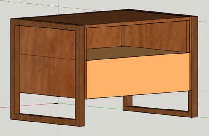
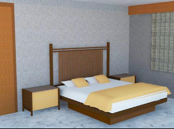
MASTER BED LAYOUT FRONT ELEVATION
Master bed
SIDE ELEVATION
99
Architects
Asif Kadri’s Residence by Umang Shah
DETAIL - 2
DETAIL - 1
DETAIL - 3
SIDE SECTION
DETAIL - 4
DETAIL - 3
2
DETAIL - 1 DETAIL -
DETAIL - 4 side unit 3D
PROJECTOR SCREEN STUDY TABLE TV UNIT SLIDING GLASS DOOR
3
DETAIL -
Devanshi Piyush Patel M.ARCH 1 | COLLEGE OF DESIGN, ART, ARCHITECTURE AND PLANNING patel6d5@mail.uc.edu | Contact: +1 5133131561 thank you for flipping through......


 a. Board (Form)
b. Board 50% reduced from original size + String
a. Board (Branching )
b. Board 50% reduced from original size+ String
a. Board (progression)
Form and
of
components for a Cantilever model


 Furniture: Wood and Metal


 Furniture: Wood and Metal


