Efficiency + Economy
+
+
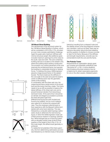
West core
Gravity frame
=
Braced frame
+
Total structure
Web wall 2.10
W
0.5P
0.5P
H
0.5P
0.5P
0.5P PH W
0.5P PH W
0.75H
2.12
92
100 Mount Street Building The development of the structural system for the 100 Mount Street Building in Sydney, which will be completed in 2019 (Fig. 2.13), provided an even more complex optimisation challenge. Again the goals were maximum stiffness with minimal structural weight. But additional goals included maximum openings for prime views to the south, east and north. The core containing building services is located on the western end, where the building abuts existing construction. The eccentric non-central placement of the core improves the architectural layout, but exposes the building to undesirable torsional or twisting forces. To address this issue, SOM engineers placed a mega-braced frame on the eastern facade. The frame balances the stiffness of the core walls to the west and pulls the tower’s centre of stiffness back near the geometric centre of the building. In combination with the shear wall core, the mega-braced frame resists winds on the broad face and the torsion that they create. This frame needs to be as stiff as possible to balance the lateral stiffness of the shear wall core and to prevent torsional vibration from becoming a dominant mode. At the same time it should be as slender and elegant as possible to promote the least disrupted sight lines. Different bracing layouts were studied and found to be suitable, but too much material was called for to achieve the required stiffness. Thus the engineers referred back to their experience with the Maxwell method and started with some hand sketches. This was followed by a computer-aided topology optimisation study to determine the best bracing layout, in which the SOM engineers made use of their previous research in topology optimisation. What emerged was an X-bracing system with an elevated central node at about threequarters of the height of the X (Fig. 2.12). At this node height, the stiffest brace geometry is achieved. To realise the full potential of this frame geom etry, the form-determining optimisation process was followed by an intensive study of structural
=
Flange wall
System 2.11
behaviour resulting from a released node and the stability issues of the long diagonal compression members. Last but not least, there was an intensive discussion about structural detailing and the question of whether to choose concrete or steel for the frame. Because of the stiffness and strength requirements, concrete was recommended for both the core and the frame. The Polestar Tower Requirements for optimisation design goals are complex and potentially antithetical (see “Structural Art”, p. 84). In some situations, benchmarking structural solutions may be a helpful tool to obtain reasonable arguments for one or the other solution. Detailed system-
2.13