D5000 PC & AS Drip Line
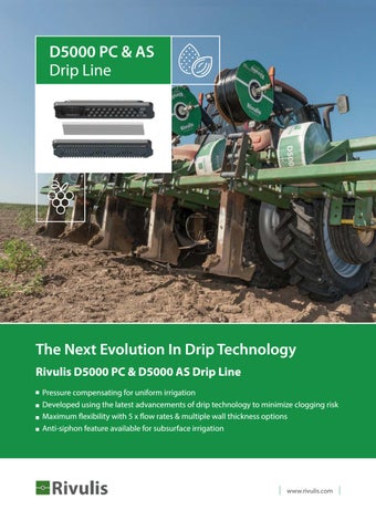
The Next Evolution In Drip Technology Rivulis D5000 PC & D5000 AS Drip Line Pressure compensating for uniform irrigation Developed using the latest advancements of drip technology to minimize clogging risk Maximum flexibility with 5 x flow rates & multiple wall thickness options Anti-siphon feature available for subsurface irrigation
www.rivulis.com
“We have hard water that often causes problems in drip irrigation. However we have found that Rivulis D5000 performs exceptionally well, even with the high mineral & high biomass content in our water.” Gali Tal, Field Crop Manager Megiddo Mt’farm, Israel
Evolution: Advancement of PC Drip Technology Rivulis PC Drip Line represents the most significant advancement of PC drip technology in the past decade. After many years of research, the Rivulis D5000 PC was launched in 2011 and set a new standard in drip line technology. From engineering designed to provide maximum resistance clogging to precision manufacturing with state of the art quality controls, Rivulis D5000 PC is the drip line to choose if compromise is not an option.
Traditional Emitters
Small inlet filtration area
Narrow & short labyrinth
Small pool area
D5000 Maximized Design
Large labyrinth Multi-zone inlet filters
Modular-linear layout, reduced filtration area Increased clogging risk, small outlet area
Large outlet area
Every component maximized Outstanding performance & resistance to clogging
2
40 independent inlet filters across 3 zones in every Rivulis D5000 PC emitter
Inlet filters are your first layer of protection against foreign particles. Rivulis D5000 PC features a unique multi-zone inlet area with 40 inlet filters to provide maximum protection to clogging and almost 300% functional filtration area compared to main competitive product in the market.
Extra wide flow labyrinth
Advanced engineering of the Rivulis D5000 PC labyrinth provides the ultimate balance of incrementally reducing flow while also forming high turbulence in the emitter to help ensure solids stay in suspension. Rivulis D5000 PC features one of the largest flow paths available to help prevent clogging.
Full size outlet pool
Dirt ingestion is a risk for all drip irrigation systems. The unique long outlet pool of the Rivulis D5000 PC in conjunction with the raised wall design provides the maximum distance between the emitter outlet and the tube hole to help prevent dirt suck-back. The full size pool also allows a true slit outlet in 15 mil configurations.
3
Evolution: Precision Manufacturing & Quality
4
Automated Assembly
In-Line Monitoring
Testing
Every emitter manufactured goes through a multi-stage automated testing process to ensure correct assembly
A photo of every inserted emitter is taken (up to 7 per second) to ensure correct alignment in the drip line during production
Before dispatch, Rivulis D5000 PC must meet a number of stringent tests including, flow test, tube analysis, weld strength and tensile strength tests
Delivering Outstanding Crop Uniformity With one of the widest flow regulating ranges available, D5000 PC provides outstanding uniformity even on undulating terrain or long run lengths. This helps ensure that your crop at the end of rows receives the same amount of water as those at the start for more consistent yields.
Rivulis D5000 PC Flow / Pressure 3.80 3.60 3.40 3.20
Nominal Flow Rate (l/h)
3.00 2.80
0.65 l/h
2.60
1.0 l/h
2.40
1.5 l/h
2.20
2.0 l/h 3.5 l/h
2.00 1.80 1.60 1.40 1.20 1.00 0.80 0.60 0.40 0.20 0
0
0.5
1.0
1.5
2.0
2.5
3.0
3.5
Pressure (bar)
Anti-Siphon: Rivulis D5000 AS Now Available In conditions where risk of soil ingestion at shut-off is high, Rivulis D5000 AS protects you through anti-siphon diaphragm technology. When there is negative pressure in the hose (i.e. a vacuum caused at system shut-off ), the membrane lowers against the inlet filters, which in turn slows the reverse of water. The stronger the vacuum, the stronger the seal that is made. Rivulis D5000 AS – additional protection to your subsurface irrigation system.
Drip Line With Positive Pressure In Hose Pressure in hose raises pressure regulating diaphragm, allowing water to enter the Rivulis D5000 emitter through the emitter inlet
Drip Line With Negative Pressure (Vacuum) In Hose Negative pressure (vacuum) in the hose causes the diaphragm to create a seal against the raised edges of the emitter inlet, preventing suck-back through the emitter
5
D5000 PC & D5000 AS | Performance Data Nominal Ø mm
16
17
20
22 23 25 27
16
17
20
22 23
6
Wall Thickness
Internal Outside Flow Ø Ø Rate
mil
mm
mm
mm
15*
0.38
16.1
30
0.76
35
l/h
Max. Max. Run Length (m) x Spacing Between Emitters (cm) Roll Op. Length 15 20 30 40 50 60 75 100 Pressure bar
m
m
m
m
m
m
m
m
m
16.86
2.2
800**
176
225
315
396
472
541
638
785
13.8
15.32
2.5
600
133
172
243
308
369
425
503
624
0.89
13.8
15.58
3.0
500
144
186
263
333
399
460
545
676
40
1.02
13.8
15.83
3.5
400
153
198
280
355
425
490
581
721
45
1.14
13.8
16.09
3.5
300
153
198
280
355
425
490
581
721
18
0.45
15.3
16.2
2.2
1100
162
207
290
364
433
496
585
720
25
0.64
15.3
16.57
2.5
800
171
219
306
386
459
526
620
763
35
0.89
15.3
17.08
3.0
450
185
237
331
417
496
569
671
826
40
1.02
15.3
17.33
3.5
450
197
252
353
445
529
607
717
882
45
1.14
15.3
17.59
3.5
400
197
252
353
445
529
607
717
882
35
0.89
17.6
19.38
3.0
350
250
318
441
551
652
745
875
1072
40
1.02
17.6
19.63
3.5
350
266
339
470
588
695
795
935
1145
45
1.14
17.6
19.89
3.5
350
266
339
470
588
695
795
935
1145
47
1.19
17.6
19.99
3.5
350
266
339
470
588
695
795
935
1145
15*
0.38
22.2
22.96
1.8
800
332
415
562
692
810
919
1070 1299
25
0.64
22.2
23.47
2.5
500
386
483
656
808
946
1073 1250 1519
40
1.02
20.8
22.84
3.0
350
362
456
623
770
904
1028 1201 1461
15*
0.38
25
25.76
1.4
700
372
462
619
757
882
998
18
0.45
25.0
25.9
1.7
600
412
512
686
840
979
1108 1286 1557
40
1.02
25.0
27.03
2.7
350
499
623
842
1034 1210 1371 1597 1936
15*
0.38
16.1
16.86
2.2
800**
132
169
237
298
356
408
482
594
30
0.76
13.8
15.32
2.5
600
101
130
184
234
280
322
383
474
35
0.89
13.8
15.58
3.0
500
109
140
199
252
302
349
414
513
40
1.02
13.8
15.83
3.5
400
116
149
212
269
322
371
441
547
45
1.14
13.8
16.09
3.5
300
116
149
212
269
322
371
441
547
18
0.45
15.3
16.2
2.2
1100
122
157
219
276
328
377
445
547
25
0.64
15.3
16.57
2.5
800
128
164
230
290
345
396
467
576
35
0.89
15.3
17.08
3.0
450
139
179
251
316
376
432
510
628
40
1.02
15.3
17.33
3.5
450
148
190
267
337
401
461
544
670
45
1.14
15.3
17.59
3.5
400
148
190
267
337
401
461
544
670
35
0.89
17.6
19.38
3.0
350
189
241
334
418
495
566
665
815
40
1.02
17.6
19.63
3.5
350
201
256
356
446
528
604
710
870
45
1.14
17.6
19.89
3.5
350
201
256
356
446
528
604
710
870
47
1.19
17.6
19.99
3.5
350
201
256
356
446
528
604
710
870
15*
0.38
22.2
22.96
1.8
800
253
316
428
527
617
700
816
990
25
0.64
22.2
23.47
2.5
500
290
364
494
609
714
810
944
1147
40
1.02
20.8
22.84
3.0
350
273
344
470
582
683
778
908
1106
0.65
1.00
1159 1402
D5000 PC & D5000 AS | Performance Data Nominal Ø mm 25 27
16
17
20
22 23 25 27
16
17
20
Wall Thickness
Internal Outside Flow Ø Ø Rate
mil
mm
mm
mm
15*
0.38
25.0
25.76
18
0.45
25.0
25.9
40
1.02
25.0
15*
0.38
30
l/h
Max. Roll Op. Length Pressure
Max. Run Length (m) x Spacing Between Emitters (cm) 15
20
30
40
50
60
75
100
bar
m
m
m
m
m
m
m
m
m
1.4
700
282
350
469
574
670
758
881
1066
1.7
600
312
388
521
637
743
841
977
1183
27.03
2.7
350
376
470
636
782
915
1037 1208 1466
16.1
16.86
2.2
800**
101
130
183
231
275
316
373
459
0.76
13.8
15.32
2.5
600
77
100
141
179
215
248
294
365
35
0.89
13.8
15.58
3.0
500
83
107
152
194
232
268
318
395
40
1.02
13.8
15.83
3.5
400
89
114
163
206
248
286
340
421
45
1.14
13.8
16.09
3.5
300
89
114
163
206
248
286
340
421
18
0.45
15.3
16.2
2.2
1100
94
120
169
212
253
290
342
422
25
0.64
15.3
16.57
2.5
800
98
126
177
223
266
305
360
444
35
0.89
15.3
17.08
3.0
450
107
137
193
243
289
332
393
484
40
1.02
15.3
17.33
3.5
450
114
146
205
259
309
355
419
516
45
1.14
15.3
17.59
3.5
400
114
146
205
259
309
355
419
516
35
0.89
17.6
19.38
3.0
350
145
185
257
322
381
436
512
628
40
1.02
17.6
19.63
3.5
350
154
197
274
343
406
465
547
671
45
1.14
17.6
19.89
3.5
350
154
197
274
343
406
465
547
671
47
1.19
17.6
19.99
3.5
350
154
197
274
343
406
465
547
671
15*
0.38
22.2
22.96
1.8
800
194
243
330
406
476
540
629
764
25
0.64
22.2
23.47
2.5
500
223
280
380
469
550
625
728
886
40
1.02
20.8
22.84
3.0
350
209
264
362
448
527
599
701
853
15*
0.38
25.0
25.76
1.4
700
217
269
362
442
517
584
680
822
18
0.45
25.0
25.9
1.7
600
241
300
402
493
575
651
757
917
40
1.02
25.0
27.03
2.7
350
289
361
489
602
705
800
932
1131
15*
0.38
16.1
16.86
2.2
800**
84
108
152
191
228
262
309
381
30
0.76
13.8
15.32
2.5
600
64
82
117
149
178
206
245
303
35
0.89
13.8
15.58
3.0
500
69
89
126
161
193
223
264
328
40
1.02
13.8
15.83
3.5
400
73
95
135
171
205
237
282
350
45
1.14
13.8
16.09
3.5
300
73
95
135
171
205
237
282
350
18
0.45
15.3
16.2
2.2
1100
77
99
140
176
210
241
284
350
25
0.64
15.3
16.57
2.5
800
81
104
147
185
221
253
299
368
35
0.89
15.3
17.08
3.0
450
88
114
160
202
240
276
326
402
40
1.02
15.3
17.33
3.5
450
94
120
169
213
255
293
346
426
45
1.14
15.3
17.59
3.5
400
94
120
169
213
255
293
346
426
35
0.89
17.6
19.38
3.0
350
120
153
213
267
316
362
426
522
40
1.02
17.6
19.63
3.5
350
128
163
227
284
337
386
455
558
45
1.14
17.6
19.89
3.5
350
128
163
227
284
337
386
455
558
47
1.19
17.6
19.99
3.5
350
128
163
227
284
337
386
455
558
1.00
1.50
2.00
* Not available in AS. ** For 16/15 with emitter spacing less than 20 cm, the roll length is 600 m.
7
D5000 PC & D5000 AS | Performance Data Nominal Ø mm 22 23 25 27
16
17
20
22 23 25 27
Wall Thickness
Internal Outside Flow Ø Ø Rate
mil
mm
mm
mm
15*
0.38
22.2
25
0.64
40
l/h
Max. Roll Op. Length Pressure
Max. Run Length (m) x Spacing Between Emitters (cm) 15
20
30
40
50
60
75
100
bar
m
m
m
m
m
m
m
m
m
22.96
1.8
800
161
202
274
338
396
449
524
636
22.2
23.47
2.5
500
185
232
316
390
457
520
606
737
1.02
20.8
22.84
3.0
350
174
219
300
372
438
499
582
710
15*
0.38
25.0
25.76
1.4
700
180
224
301
368
430
486
566
684
18
0.45
25.0
25.9
1.7
600
200
249
335
410
478
542
630
763
40
1.02
25.0
27.03
2.7
350
240
300
407
500
587
665
776
941
15*
0.38
16.1
16.86
2.2
800**
58
75
105
133
159
182
215
266
30
0.76
13.8
15.32
2.5
600
44
57
81
103
123
142
170
210
35
0.89
13.8
15.58
3.0
500
47
61
87
111
134
154
183
228
40
1.02
13.8
15.83
3.5
400
50
65
84
118
149
178
230
276
45
1.14
13.8
16.09
3.5
300
50
65
84
118
149
178
230
276
18
0.45
15.3
16.2
2.2
1100
54
69
97
122
146
167
197
244
25
0.64
15.3
16.57
2.5
800
57
72
102
129
154
177
209
258
35
0.89
15.3
17.08
3.0
450
61
79
111
140
167
191
227
280
40
1.02
15.3
17.33
3.5
450
65
84
118
149
178
205
242
298
45
1.14
15.3
17.59
3.5
400
65
84
118
149
178
205
242
298
35
0.89
17.6
19.38
3.0
350
83
106
148
185
220
252
296
364
40
1.02
17.6
19.63
3.5
350
88
113
158
198
235
269
317
388
45
1.14
17.6
19.89
3.5
350
88
113
158
198
235
269
317
388
47
1.19
17.6
19.99
3.5
350
88
113
158
198
235
269
317
388
15
0.38
22.2
22.96
1.8
800
111
140
190
234
275
313
365
443
25
0.64
22.2
23.47
2.5
500
129
162
221
274
321
365
426
518
40
1.02
20.8
22.84
3.0
350
121
153
210
260
307
349
408
498
15
0.38
25.0
25.76
1.4
700
125
156
210
257
300
340
395
479
18
0.45
25.0
25.90
1.7
600
139
173
233
286
334
379
441
534
40
1.02
25.0
27.03
2.7
350
67
210
285
351
411
466
544
661
2.00
3.50
* Not available in AS. ** For 16/15 with emitter spacing less than 20 cm, the roll length is 600 m.
8
Rivulis D5000 PC Flow Regulating Drip Line with Anti-Siphon Option Drip Line
D5000 PC
Mechanism
Pressure differential from silicon diaphragm with self-cleaning feature
Pressure compensating / Flow regulating Anti-Siphon
D5000 AS available
Flow Rates (l/h)
0.65, 1.0, 1.5, 2.0, 3.5
Nominal Drip Line Diameter (mm)
Outlet
16, 17, 20, 22, 23, 25, 27 15 (0.38 mm), 18 (0.45 mm) 25 (0.63 mm), 30 (0.76 mm), 35 (0.89 mm), 40 (1.02 mm), 45 (1.14 mm), 47 (1.19 mm) Slit (PC - 15 mil wall thickness), hole (all other configurations)
Operating Pressure Range (bar)
0.5 – 3.5 (according to diameter and wall thickness)
Drip Line Wall Thickness (mil)
9
“The Rivulis D5000 subsurface drip irrigation system stands out for multiple reasons. The system uses far less water, fertilizer and chemicals compared to overhead irrigation. Additionally, the application of fertilizers and chemicals is much easier. It is possible to be precise with both quantity and timing, including daily application if required to maximize efficiency. Traditional irrigation techniques on the other hand are much less precise, and therefore result in wasted fertilizers and chemicals, along with high mechanical costs.”
Paulo Sérgio Fragnito, Vista Alegre Farm, Brazil
Case study outcomes are for information purposes only and actual results may vary. This literature has been compiled for worldwide circulation and the descriptions, photos, and information are for general purpose use only. Please consult with an irrigation specialist and technical specifications for proper use of Rivulis products. Because some products are not available in all regions, please contact your local dealer for details. Rivulis reserves the right to change specifications and the design of all products without notice. Every effort has been used to ensure that product information, including data sheets, schematics, manuals and brochures are correct. However information should be verified before making any decisions based on this information.
www.rivulis.com