Model 610CV Mass Flow Controller

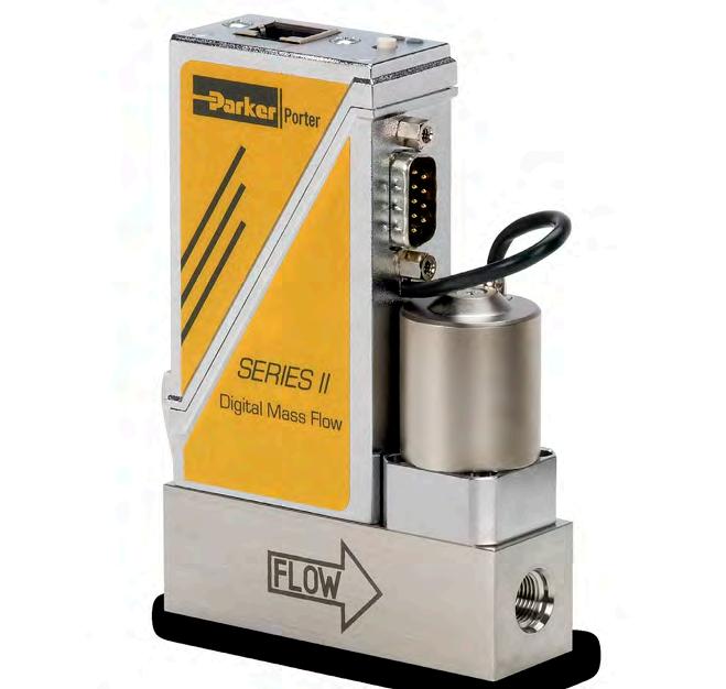
Porter’s Model 610CV Series II Mass Flow Controller (MFCs) is designed for precise control of virtually all conventional process gases. The MFC consists of a thermal mass flow sensor, a precise control valve and a microprocessor based PID controller with signal and fieldbus conversion. Based on the setpoint input value, the flow controller swiftly adjusts to the desired flow rate. The mass flow rate is provided as analog signal or digitally via RS232 or various fieldbus options. Each unit is specifically sized and calibrated depending on the types of gas and the process conditions of the application.

Product Features: • Full Scale Flow Ranges from 0.7 ml/min to 9 ml/min • Operating Pressures up to 1450 PSIA • High accuracy and repeatability • Storage of max. 8 calibration curves • User configurable control characteristics • Flow Parameter Adjust functionality up to 150 PSIA • Effective Rangeability <180:1 • Analog or digital: RS232, DeviceNet™ , ProfibusDP® , Modbus-RTU
500/600 Series II Flowmeter Products
Thermal Mass Flow Measuring Principle
The Mass Flow Sensing System consists of a stainless steel capillary tube with two precision heater and temperature sensing elements wound around the outside of the tube. As gas flows through the capilliary tube, heat is displaced to the downstream temperature sensor creating a differential between the two sensors. The difference is directly proportional to mass flow through the tube. In the main flow channel, a patented laminar flow element package creates a restriction that forces a fixed percentage of the total flow through the sensor for temperature differential detection.
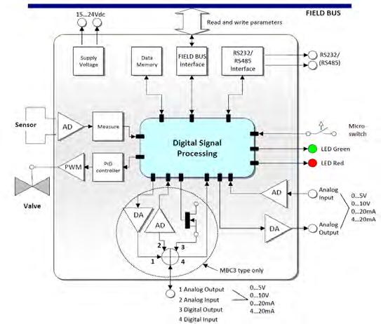
State of the Art Digital Design
Porter’s Series II Mass Flow products are equipped with a microprocessor based digital pc-board offering high accuracy, excellent temperature stability and fast MFC response time. The basic digital pc-board contains all of the general functions needed for measurement and control. RS232 communication and analog I/O are included. An optional integrated communication interface board provides DeviceNet™ , Profibus-DP® or Modbus-RTU.
Temperature profile without flow
Temperature profile with flow
temperature
Sensor tube Laminar flow element ΔT = k.C p .Ø m ΔT = T2-T1 in Kelvin C p = specific heat Øm = mass flow
Models and Flow Ranges
Model
610CV-A
Heater 1 and Temperature measurement 1 Heater 2 and Temperature measurement 2
Minimum Nominal Maximum
0.014 to 0.7 ml/min 0.014 to 2 ml/min 0.014 to 5 ml/min
610CV-B 0.6 to 3 ml/min 0.6 to 5 ml/min 0.6 to 9 ml/min
All flow ranges are at standard conditions of 14.7 PSIA and 70°F (21.1°C)
Ambient
Turbulence filter Flow Measured ΔT Medium temperature
Specifications
Measurement / Control System
Accuracy (incl. linearity) (based on actual calibration)
Standard: ±0.5% Reading plus ±0.1% Full Scale (±1% Full Scale for ranges 3-5 ml/min; ±2% Full Scale for ranges < 3 ml/min)
Turndown 1 : 50 (in digital mode up to 1 : 187.5)
Repeatability <0.2% Reading
Settling Time (Controller) Standard: 2-4 seconds Control Stability <±0.1% Full Scale (typical for 1 l/min N2)
Operating Temperature -10 to +70°C
Temperature Sensitivity Zero: <0.05% Full Scale/°C; span: <0.05% Reading/°C Pressure Sensitivity 0.1%/ATM typical N2; 0.01%/ATM typical H2 Leak Integrity, outboard Tested < 2 x 10⁻⁹ mbar l/s He Attitude Sensitivity Max. error at 90° off horizontal 0.2% at 1 ATM, typical N2
Warm-Up Time 30 min. for optimum accuracy 2 min. for accuracy ±2% Full Scale
Mechanical Parts
Material (wetted parts) Stainless steel 316L or equivalent Surface Quality (wetted parts) Ra= 0.8µm typical Process Connections Compression or face seal fittings
Seals Standard: Viton Options: EPDM, Kalrez (FFKM)
Ingress Protection (housing) IP40
Electrical Properties
Power Supply
+15-24 Vdc
Power Consumption Meter: 70 mA; Controller: max. 320 mA; Add 50 mA for Profibus, if applicable
Analog Output/Command 0-5 (10) Vdc or 0 (4)-20 mA - specify(Sourcing output)
Digital Communication
Standard: RS232 Options: Profibus-DP®, DeviceNet™, EtherCAT®, Modbus Electrical Connection
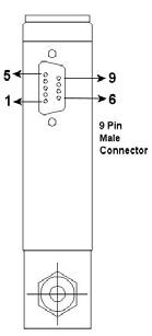
Analog/RS232
9-pin D-connector (male)
Profibus-DP® Bus: 9-pin D-connector (female) Power: 9-pin D-connector (male)
DeviceNet™ 5-pin M12-connector (male)
EtherCAT® 2 x RJ45 modular jack (in/out)
Modbus-RTU/FLOW-BUS RJ45 modular jack
Technical specifications and dimensions subject to change without notice.
0.811 (20.6)
(28.6) Fitting 1/16’’
Fitting 1/8’’
Fitting 1/4’’
(27.6) Fitting 3/8’’
Fitting 1/8’’ inlet 0.701 (17.8) Fitting 1/4’’ inlet 0.933 (23.7)
Ordering Information 6 0 0CV A A A D 1 1 V Model 6 Controller Pressure Rating 1 1450 PSIA Flow Ranges 0CV 0 to 0.7 / 0 to 9 ml/min Nominal Range Factory Selected Communication (I/O) A RS232 + Analog, N.C. Valve B RS232 + Analog, N.O. Valve D RS232 + DeviceNet, N.C Valve E RS232 + DeviceNet, N.O. Valve M RS232 + Modbus-RTU, N.C. Valve N RS232 + Modbus-RTU, N.O. Valve P RS232 + Profibus -DP, N.C. Valve Q RS232 + Profibus - DP, N.O. Valve R RS232 + FLOW-BUS, N.C. Valve S RS232 + FLOW-BUS, N.O. Valve Analog I/O A 0 to 5 Vdc B 0 to 10 Vdc F 0 to 20 mA Sourcing G 4 to 20 mA Sourcing Elastomers V Viton (Factory Standard) E EPDM K Kalrez (FFKM) Connections
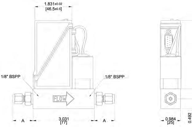
1 1/8’’ OD Compression 2 1/4’’ OD Compression 3 6 mm OD Compression 8 1/4’’ Face Seal Male 9 Other 0 None Supply Voltage D +15 to 24 Vdc Dimensions
(in/out)
1/8’’BSPP Compression Size A
OD
OD
Fitting 3 mm
0.996 (25.3) Fitting 6 mm
1.087 (27.6) Fitting 8 mm OD 1.126
OD
OD 0.996 (25.3)
OD 1.087
OD 1.161 (29.5)
Face-Seal Male Size A
Bracket = Millimeters
(Millimeters)
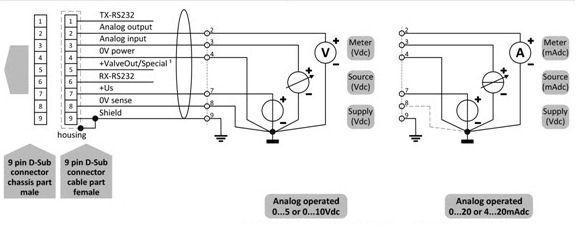
Hook-up Diagram for Analog or RS232 Communication
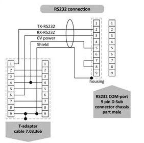
Note: Pin 4 and Pin 8 should be seperatly and connected to power common at the power supply.
Note: When using a unit configured for a fieldbus or RS232 I/O, it is not possible to operate the instrument using analog I/O without changing the “control mode” parameter. (See users manual)
Note: For hookup details of modbus, Profibus or DeviceNet communications, see users manual.
Note: Do not connect external valve to instruments configured as flow meters
Note: Valve out signal is 0 - 10 Vdc, .1mA
WARNING – USER RESPONSIBILITY
FAILURE OR IMPROPER SELECTION OR IMPROPER USE OF THE PRODUCTS DESCRIBED HEREIN OR RELATED ITEMS CAN CAUSE DEATH, PERSONAL INJURY AND PROPERTY DAMAGE.
This document and other information from Parker-Hannifin Corporation, its subsidiaries and authorized distributors provide product or system options for further investigation by users having technical expertise.
The user, through its own analysis and testing, is solely responsible for making the final selection of the system and components and assuring that all performance, endurance, maintenance, safety and warning requirements of the application are met. The user must analyze all aspects of the application, follow applicable industry standards, and follow the information concerning the product in the current product catalog and in any other materials provided from Parker or its subsidiaries or authorized distributors.
To the extent that Parker or its subsidiaries or authorized distributors provide component or system options based upon data or specifications provided by the user, the user is responsible for determining that such data and specifications are suitable and sufficient for all applications and reasonably foreseeable uses of the components or systems.

Offer of Sale
The items described in this document are hereby offered for sale by Parker-Hannifin Corporation, its subsidiaries or its authorized distributors. This offer and its acceptance are governed by the provisions stated in the detailed “Offer of Sale” elsewhere in this document or available at www.parker.com/offerofsale.
WS-0033 Rev. 0 5/14
Porter Instrument Division
245 Township Line Road
Hatfield, PA 19440
phone 215 723 4000 fax 215 723 2199 industrial@parker.com www.parker.com/porter
Parker Hannifin Corporation
