MPC Series Mass Flow Controller
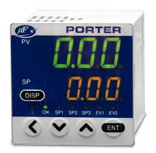
Porter MPC Series Mass Flow Controllers represent a totally new concept in cost-efficient mass flow control. These units contain both a fast and accurate mass flow controller and the necessary electronics for a complete closed-loop control system, all in a compact, panel mount, 1/16 DIN package. The front panel includes the interface for all functions, as well as readouts for setpoint, flow rate and total flow. Alarms, batch control and multiple setpoints are programmable for enhanced versatility. The MPC Series operates on 24 Vdc and has remote analog I/O capability.These controllers are available in fullscale flow rates of 0.5, 2.0, 5.0, and 20.0 SLPM N2.
FEATURES:

•
MULTIPLE SETPOINTS
Up to 4 setpoints can be switched via front panel or external input.
•
GAS CORRECTION
Air,N2, Argon, and CO2 standard. Conversion factors for mixtures and other gases can be entered through front panel.
• INTEGRATED TOTALIZER 8-digit totalizer can be reset via front panel key function. Start/stop/reset via external switching input.Valve shut-off can be enabledat preset total flow value.
• ALARM INDICATION
•
VALVE OVERIDE
Control valve can be programmed for normal control, full open or full closed.
Flow alarm can be set to upper and lower deviation limits between setpoint and flow rate. Alarm delay time is adjustable Alarm condition can trigger external output or valve override open/closed.
•
AUTOMATIC VALVE SHUT-OFF
Internal control valve can be shut-off when predetermined totalizer value is reached or when alarm occurs.
•
VALVE DRIVE OUTPUT MONITOR
Valve voltage status can prewarn of system abnormalities.
•
OPTIONAL COMPUTER INTERFACE
•
SLOW START FUNCTION
Response can be set for a ramp of up to 6 seconds.
Upload and download of setpoint, flow rate, and various function parameters possible via one-to-one computer communications cable.
Model Numbers and Flow Ranges
Model Number
MPC95
Flow Range (SLPM)
MPC02
MPC05 MPC20
Setpoint/Display Resolution (SLPM) Flow Range (SLPM) Setpoint/Display Resolution (SLPM) Flow Range (SLPM) Setpoint/Display Resolution (SLPM) Flow Range (SLPM) Setpoint/Display Resolution (SLPM)
Nitrogen/Air 0.020 to 0.5000.0020.08 to 2.000.010.10 to 5.000.020.4 to20.00.1 Argon 0.020 to 0.5000.0020.08 to 2.000.010.10 to 5.000.020.4 to 20.00.1 Carbon Dioxide 0.012 to 0.3000.0010.040 to 1.2000.0050.06 to 3.000.010.3 to 16.00.1
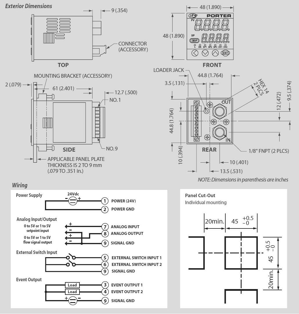
Dimensions
Control Valve Type Normally closed proportional solenoid valve
Maximum Flow Capacity (N2 Equivalent) (Note 1) 0.5 SLPM 2.0 SLPM 5.0 SLPM 20.0 SLPM
Compatible Gases
Control
Pressure
Temperature
Nitrogen/Air, Argon, Carbon Dioxide Gas must be dry, clean and oil-free
Rangeability (Control Range) (Refer to Table 1) 25:1 (4-100% full scale [FS]) 50:1 (2-100% FS)
Response Time 1.0 second to within ± 2& FS of setpoint (typical)
Accuracy ± 2% FS (at 20°C and 30 PSIG Repeatability ± 1% FS Temperature Coefficent ± 0.1% FS/°C (± 0.056% FS/ °F)
Pressure Coefficent (per 14.5 PSI) Flow ≥40% FS 0.7% FS 0.4% FS 0.2% FS 0.2% FS Flow ≥10% FS Flow <40% FS 1.2% FS 0.7% FS 0.3% FS Flow <10% FS 2% FS 1.2% FS 0.5% FS
Minimum Differential Pressure (Note 3) 7 PSIG 7 PSIG 14.5 PSIG 22 PSIG
Maximum Differential Pressure (Note 4) 40 PSIG
Calibration Pressure (Note 2) 30 PSIG (inlet pressure: 30 PSIG and outlet pressure: 0 PSIG)
Maximum Operating Pressure 75 PSIG
Calibration Temperature (Note 2) 20°C
Operating Temperature Range -10 to +50°C (14 to 122°F)
Storage Temperature Range -10 to +60°C (14 to 140°F)
Humidity Operating Humidity Range 10 to 90% Relative Humidity (noncondensing)
Setpoint
Flow Rate Indication
Setpoint Input Keypad Operation or External Setpoint Voltage Input Resolution Refer to Table 1
Setpoint Input Voltage 0 to 5 Vdc or 1 to 5 Vdc (selectable)
Display Type 7-segment LED; 8 digits (Instantaneous flow rate display: 4 digits; Setpoint flow rate display: 4 digits)
Display Resolution Refer to Table 1
Indication Accuracy ±2% FS ±1 digit
Display Range 0.00 to 999,999.99L 0.0 to 9,999,999.9L0.0 to 9,999,999.9L0 to 99,999,999L
Display Resolution 0.01L 0.1L 0.1L 1L
Totalizer Function
Flow Rate
Output
Event Output
Totalizer Backup Timing Every 5L Count Every 20L CountEvery 50L CountEvery 200L Count Every hour (time) from the previous backup
Output Scale 0 to full scale flow rate (scaling selectable)
Output Signal Voltage 0 to 5 Vdc or 1 to 5 Vdc (selectable)
Maximum Signal Output Voltage 7 Vdc maximum (maximum output signal when flow rate exceeds maximum flow capacity) Accuracy ±0.5% FS (Input impedance of the connected device must be 100k ohms or greater) Overall output accuracy: Indication accuracy ±0.5% FS
Number of Outputs 2
Output Rating 30 Vdc, 15 mAdc maximum (open collector non-insulated output)
Totalizer Pulse Output
MODEL NUMBER MPC95 MPC02 MPC05 MPC20
Width 100 ms (±10%) (when
pulse output
Totalizer Pulse Output Rate 0.01L/pulse 0.1L/pulse
External Contact Input Number of Inputs 2 Input Type Potential-free contact or open collector Contact OFF Terminal Voltage 2.0 Vdc (±0.5 Vdc) Contact ON Terminal Current Approximately 0.5 mAdc (contact current) Allowable ON Contact Resistance 250 ohms maximum Allowable OFF Contact Resistance 100k ohms minimum Allowable ON Residual Voltage 1.0 Vdc maximum (with open collector) Allowable OFF Leakage Current 50 μAdc maximum (with open collector) Communication System (Note 5) Loader communication (dedicated cable required) Transmission Speed 19200 bps Power Supply Requirements 24 Vdc (±5%); current consumption 300 mAdc maximum Materials of Construction Brass (nickel-plated), stainless steel, Teflon®, Viton® Process Connections 1/8" FNPT Mounting Options Housing horizontal with inlet & outlet ports vertically oriented ('IN' - bottom & 'OUT' - top) Weight (Approximate) 10.6 oz. (300 grams) Applicable Standard CENELEC # EN61326: 1997; Amendment A1: 1998; Amendment A2: 2000 Accessory Components (Included with every MFC) Mounting bracket and mating electrical connector Note 1. SLPM indicates the volumetric flow corrected to 20°C, 1 atmosphere (14.7 PSIA). The reference temperature can also be changed to 0°C, 25°C and 35°C. The controllable flow range varies according to the gas type. Refer to Table 1 on previous page. Note 2. Temperature and pressure during calibration. Note 3. Differential pressure required for obtaining maximum flow capacity Note 4. Operation is possible with less than required minimum differential pressure, however, rangeability (control range) decreases. Note 5. Loader communications package (sold separately) is required. Teflon® - E.I. DuPont de Nemours & Co., Viton® - DuPont Dow Elastomers L.L.C. Specifications and dimensions subject to change Specifications
totalizer
is selected)
0.1L/pulse 1L/pulse
WARNING – USER RESPONSIBILITY
FAILURE OR IMPROPER SELECTION OR IMPROPER USE OF THE PRODUCTS DESCRIBED HEREIN OR RELATED ITEMS CAN CAUSE DEATH, PERSONAL INJURY AND PROPERTY DAMAGE.
This document and other information from Parker-Hannifin Corporation, its subsidiaries and authorized distributors provide product or system options for further investigation by users having technical expertise.
The user, through its own analysis and testing, is solely responsible for making the final selection of the system and components and assuring that all performance, endurance, maintenance, safety and warning requirements of the application are met. The user must analyze all aspects of the application, follow applicable industry standards, and follow the information concerning the product in the current product catalog and in any other materials provided from Parker or its subsidiaries or authorized distributors.
To the extent that Parker or its subsidiaries or authorized distributors provide component or system options based upon data or specifications provided by the user, the user is responsible for determining that such data and specifications are suitable and sufficient for all applications and reasonably foreseeable uses of the components or systems.
Offer of Sale
The items described in this document are hereby offered for sale by Parker-Hannifin Corporation, its subsidiaries or its authorized distributors. This offer and its acceptance are governed by the provisions stated in the detailed “Offer of Sale” elsewhere in this document or available at www.parker.com/safety.
WS-0020 Rev. A 11/13
