Model 201 Mass Flow Instruments
Porter Mass Flow products reflect over four decades of experience in the design and manufacture of precision instruments for the measurement and control of gas flow. They incorporate design principles that are simple and straightforward, yet flexible enough to operate under a wide variety of process parameters. The result is flowmeters, flow controllers and control valves that are accurate, reliable and cost-effective solutions for many gas flow applications in the analytical, process, chemical/ petrochemical, environmental, biopharmaceutical and research markets.
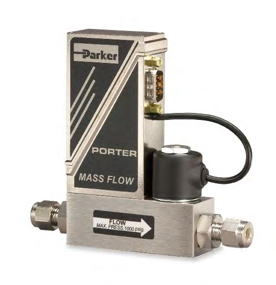
The 200 series is the lastest evolution of the original Porter Analog MFC. With thousands installed worldwide, they are the proven solution when cost effective high performance gas flow control is the goal. The 100 Series Mass Flow Meters are available for applications where flow measurement only is required.
SPECIFICATIONS:
Flow Capacity:Any Flow range from 0-5 SCCM to 0-10 SLPM (nitrogen equivalent).
Response Time (per SEMI E17-91 Settling Time):1 to 2 Seconds
Accuracy and Linearity:±1% full scale
Repeatability:Within ±0.2% full scale at any constant temperature within operating temperature range

Rangeability (Control Range):50; 1 (2%-100% full scale) (accuracy and control)
Ambient and Operating Temperature Range:-10 to 70 °C ( ±14 to 158 °F)

Maximum Operating Pressure:1000 PSIG
Temperature Coefficent (per SEMI E18-91 Zero Effect and Span Effect): ±0.05% full scale / °C of zero ±0.05% of reading/ °C of span
Mounting Orientation:Attitude insensitive
Warm-up Time:10 minutes
External Electrical Connector: Nine (9)- pin Dconnector
Weight (approximate): 1.2 lbs
Power Supply Requirements: (Current consumption <250 mAdc): Voltage output models: +12 (±5%) (0-5 Vdc & 1-5 Vdc fow signal outputs only) or +15 (±10%) Vdc Current loop models: +15 (±5%) or +24 (±15%) Vdc
Setpoint Input/Flow Signal Output: 0-5 Vdc/0-5 Vdc (2K ohm minimum load resistance)
0-10 Vdc/0-10 Vdc (3K ohm minimum load resistance) 1-5 Vdc/1-5 Vdc (2K ohm minimum load resistance) 4-20 mAdc/4-20mAdc (refer to load resistance values below) 1-5 Vdc/4-20 mAdc (refer to load resistance values below)
Load resistance values for 4-20 mAsc flow signal output: 0-450 ohm for 6.5-15 Vdc loop supply voltage 200-750 ohm for 15-30 Vdc loop supply voltage
MATERIALS OF CONSTRUCTION ORDERING INFORMATION
Body: 316 Stainless Steel
Sensor Assembly: 316L Stainless Steel
Orifice: 316 Stainless Steel
Valve Components (Wetted): 302 Stainless Steel, 316 Stainless Steel, 430F Stainless Steel and Sandvik® 1802
Elastomers (O-rings and Valve Seat): Buna N, EPDM, Kalrez®, Neoprene or Viton®
Process Connections: 316 Stainless Steel
Sandvik®, Kalrez® and Viton® are property of their respective owners
Specifcations subject to change
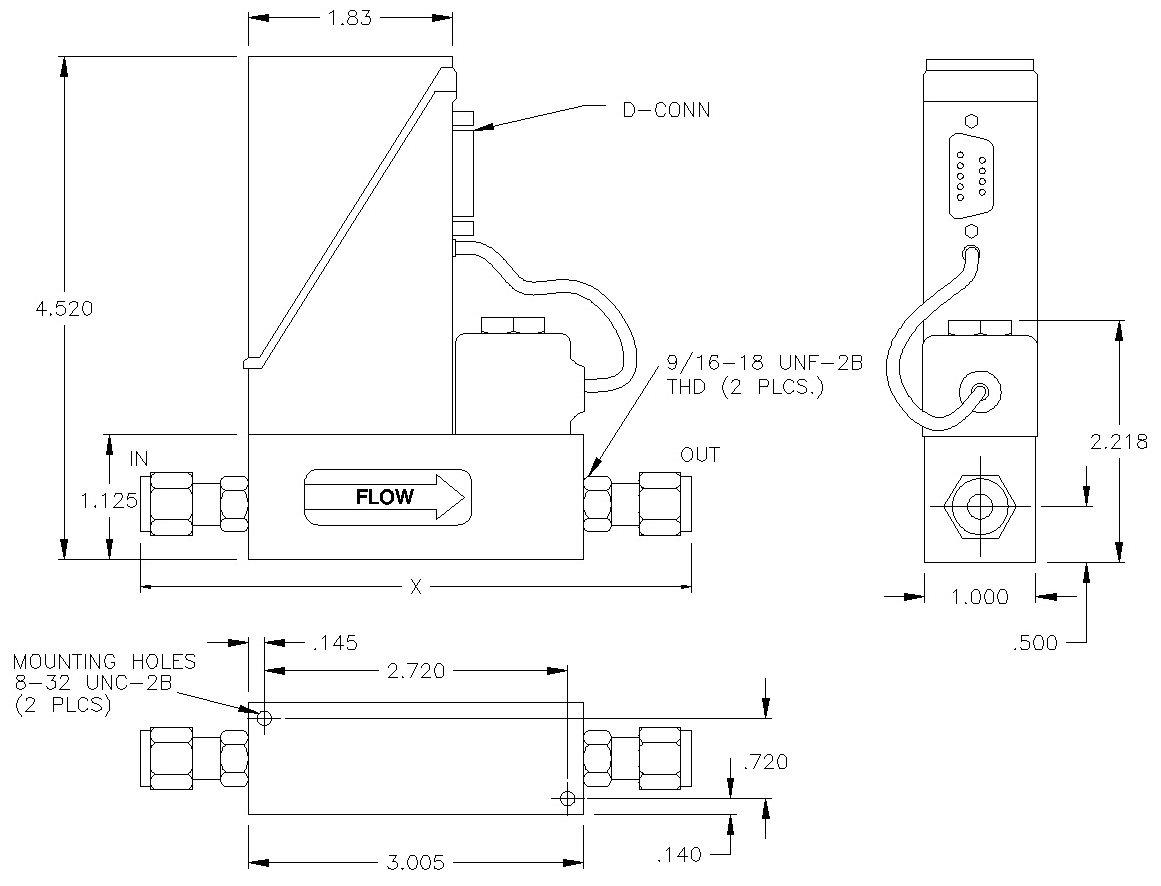
DIMENSIONAL DATA
To order, please specify: 20°C, 21.1°C or 25°C) Dimensions shown in inches
Process
1/8’’ Compression 4.845’’ 1/4’’ Compression 5.025’’ 3/8’’ Compression 5.145’’ 1/4 CPI® 5.025’’ 3/8 CPI 5.145’’ 1/4’’ A-Lok® 5.025’’ 3/8’’ A-Lok 5.145’’ 1/4’’ MMGFS 4.885’’
Connection Size & Type ‘X’ Dimension
A: 0-5 Vdc/0-5 Vdc
B: 1-5 Vdc/4-20 mAdc (sinking) D: 1-5 Vdc/1-5 Vdc E: 0-10 Vdc/0-10 Vdc

MODEL NUMBER AND DESCRIPTION 201 - F K A S V C AA Example
Model Assembly/Calibration Features 201 AA: Factory Standard Model Revision Level F : Current Revision PC Board Electrical Connector
Setpoint Signal/Output Signal
:
K: Nine (9)-Pin “D”
For model number options not shown above, please consult factory OTHER AVAILABLE ANALOG MASS FLOWMETER AND MASS FLOW CONTROLLER MODELS
Body Material
Steel
Male
Face Seal
Male Metal Gasket Face Seal Type Model Max. Flow1 (SLPM) Max. Pressure2 (PSIG) Min. Delta3 (PSIG) Analog Flow Meters 111 10 1500 2 121 10 3000 2 112 100 1500 2 122 100 3000 2 113 500 1000 2 114 1000 1000 2 2111 10 200 2 3211 10 1000 2 Type Model Max. Flow1
Analog Flow Controllers 201 10
7 261 10
7 221 10 3000 7 251 50 1000 35 202 100 1000 60 222 100 3000 60 202A 100
10 203A 500
40 204A
80
7
7 Note: The fow ranges listed are the minimum and maximum nitrogen (N2) fow ranges available for each given model. Intermediate fow ranges are available. For correct sizing when operating parameters are questionable, please consult the factory. Parker Hannifin Corporation Porter Instrument Division 245 Township Line Road Hatfield, PA 19440 USA (215) 723-4000/ fax (215) 723-2199 Process Connection Size and Type A 3/8’’ CPI™ M 1/4’’ UltraSeal® B 1/8’’ Compression P 1/4’’ MMGFS(2) C 1/4’’ Compression Q 3/8’’ MMGFS(2) D 3/8’’ Compression R 3/8’’ UltraSeal® E 1/2’’ Compression S 1/2’’ MMGFS(2) H 10 mm Compression U ® I 1/4’’ CPI™ W 6 mm Compression J (1) X No Connections K (1) Y L (1) Z Special Connections Elastomers (Valve Seat/O-Rings) B: Buna N/Buna N E: EPDM/EPDM K: Kalrez/Kalrez N: Neoprene/Neoprene V: Viton/Viton WS-0009 Rev. C 02/12
H: 4-20 mAdc/4-20 mAdc (sourcing) J : 4-20 mAdc/4-20 mAdc (sinking)
S: 316 Stainless
A-LOK®, CPI™, UltraSeal™, VacuSeal™ - Parker Hannifn Corp. (1)MORFS =
O-Ring
(2)MMGFS =
(SLPM) Max. Pressure2 (PSIG) Min. Delta3 (PSIG)
1000
1000
200
200
1000 200
2201 10 200
3201/3261 10 1000
WARNING – USER RESPONSIBILITY
FAILURE OR IMPROPER SELECTION OR IMPROPER USE OF THE PRODUCTS DESCRIBED HEREIN OR RELATED ITEMS CAN CAUSE DEATH, PERSONAL INJURY AND PROPERTY DAMAGE.
This document and other information from Parker-Hannifin Corporation, its subsidiaries and authorized distributors provide product or system options for further investigation by users having technical expertise.
The user, through its own analysis and testing, is solely responsible for making the final selection of the system and components and assuring that all performance, endurance, maintenance, safety and warning requirements of the application are met. The user must analyze all aspects of the application, follow applicable industry standards, and follow the information concerning the product in the current product catalog and in any other materials provided from Parker or its subsidiaries or authorized distributors.
To the extent that Parker or its subsidiaries or authorized distributors provide component or system options based upon data or specifications provided by the user, the user is responsible for determining that such data and specifications are suitable and sufficient for all applications and reasonably foreseeable uses of the components or systems.
Offer of Sale
The items described in this document are hereby offered for sale by Parker-Hannifin Corporation, its subsidiaries or its authorized distributors. This offer and its acceptance are governed by the provisions stated in the detailed “Offer of Sale” elsewhere in this document or available at www.parker.com/offerofsale.
Parker Hannifin Corporation
Porter Instrument Division 245 Township Line Road Hatfield, PA 19440 USA (215) 723-4000/ fax (215) 723-2199
WS-0009 Rev. C 02/12
