

Welded Fittings Catalog 4280 November 2011

Huntsville, Alabama, USA
FAILURE OR IMPROPER SELECTION OR IMPROPER USE OF THE PRODUCTS DESCRIBED HEREIN OR RELATED ITEMS CAN CAUSE DEATH, PERSONAL INJURY AND PROPERTY DAMAGE.
This document and other information from Parker-Hannifin Corporation, its subsidiaries and authorized distributors provide product or system options for further investigation by users having technical expertise.
The user, through its own analysis and testing, is solely responsible for making the final selection of the system and components and assuring that all performance, endurance, maintenance, safety and warning requirements of the application are met. The user must analyze all aspects of the application, follow applicable industry standards, and follow the information concerning the product in the current product catalog and in any other materials provided from Parker or its subsidiaries or authorized distributors.
To the extent that Parker or its subsidiaries or authorized distributors provide component or system options based upon data or specifications provided by the user, the user is responsible for determining that such data and specifications are suitable and sufficient for all applications and reasonably foreseeable uses of the components or systems.
The items described in this document are hereby offered for sale by Parker-Hannifin Corporation, its subsidiaries or its authorized distributors. This offer and its acceptance are governed by the provisions stated in the detailed “Offer of Sale” elsewhere in this document or available at www.parker.com/ipdus.
© Copyright 2011, Parker Hannifin Corporation. All Rights Reserved
Parker Hannifin Corporation Instrumentation Products Division Huntsville, AL USA http://www.parker.com/ipdus

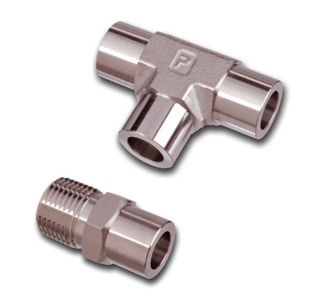
In the chemical industry, process pressures are climbing higher and higher. The utility field, with its high steam pressures and hydraulic and pneumatic shutdown systems, demands the utmost in reliability. Nuclear power plants with their “hot” materials also have massive reliability problems. Such problem areas have given rise to the increased use of the permanent-weld-type tube fittings which provide a sturdy, tight integral line system that remains unaffected by shock, vibration or thermal distortion. The Parker Weldlok® line of permanent socket weld tube fittings meets the most exacting requirements of any system.
Parker Hannifin’s Instrumentation Products Division offers Heat Code Traceability (HCT) on CPI™, A-LOK®, Instrumentation Pipe, Automatic Buttweld, and Weld-lok®.
HCT refers to the fact that a specific part can be traced back to the original mill heat of metal from which it was made. Beginning with the original melt, a package of documents is created which completely describes the metal in physical and chemical terms. The end result is that a number, which is permanently stamped to the part, refers back to the document package.
The HCT number is stamped on the material (bar stock or forging) prior to manufacturing. The concept is useful because it provides a method for complete material accountability for the manufacturer and end customer.
additional information
HCT offers these advantages:
Raw materials for manufacture must meet code requirements. This can be verified through documentation so that the customer is certain that what is ordered is received.
HCT provides a record of chemical analysis with the raw material. Thus, in areas requiring welding, the correct welding technique is applied.
HCT relieves the user of Parker instrumentation tube fittings of any doubts. It acts as an assurance for today and for tomorrow.
The material used in Parker Hannifin instrumentation fitting components is 316 stainless steel as specified and referenced in Section III of the ASME Boiler and Pressure Vessel code.
The American Society of Mechanical Engineers (ASME) Boiler and Vessel Code, Section III, latest issue, entitled Rules for Construction of Nuclear Power Plant Components, is the principal document covering this type of fitting in the nuclear field. ANSI Standard B.31.1, Power Piping, and ANSI Standard B.31.7, Nuclear Power Piping, are also important documents in the field.
In addition to the documentation of chemical and physical properties, great care is taken throughout the manufacture of Parker’s tube fittings to ensure that potential stress corrosion will not be a problem in normal usage of the parts. Manufacturing processes avoid exposure of the parts to mercury or halogens, and control of thermal treatment avoids the condition known as continuous grain boundary carbide precipitation (see page 4).
Parker Hannifin Corporation Instrumentation Products Division Huntsville, AL USA http://www.parker.com/ipdus
The weld used in joining a tube to a socket weld tube fitting is like any other type of “tee” weld. The root (i.e., the point of intersection of the outside of the tube and annular end area of the fitting) must be included in the weld zone.
Careful welding procedures are normally followed to assure that this root area is included in the weld. If penetration is not achieved, the joint will have two builtin stress risers which may greatly reduce the strength of the weld. Upon application of an extreme load, these stress risers could result in cracks which could propagate out through the weld or tube depending upon the direction of the greatest load.
Often to achieve full root penetration in TIG welding of stainless steels, a fusion pass will be made first, followed by an final pass utilizing a filler rod to achieve the desired fillet size.
The codes applicable to the welding of socket weld fittings require that the tube be inserted into the socket until bottomed against the stop. The tube is then to be backed out approximately 1/16 of an inch and then welded.
If the tube is not backed out, but welded when against a flat bottom stop, the contraction of the weld fillet and fitting socket can combine to produce a static stress on the weld. During thermal transients, the fitting and the portion of the tube within the fitting may experience a differential rate of heating or cooling, again adding to the stress level in the weld.
If the weld joint is to be “tacked” before welding, it is recommended that the “tack” weld build-up be held to a minimum.
Excessive build-up on the “tack” may cause an interrupted final bead and a stress riser or lack of complete fusion.
Backing gas is an inert (no active properties) gas used to flood the interior of the fittings and tube system during welding. It serves the same purpose internally as the shielding gas used in TIG or MIG welding. By reducing the interior oxygen level to as low as practicable, it also serves to control the combustion of contaminates that could affect weld quality.
When a backing gas is not used and nearly 100% weld penetration is achieved, blisters will tend to form on the internal tube wall. This will result in scale which
may later break loose. Therefore, in 0.050 wall or thinner tube or where the wall thickness is such that the selected weld process may burn through, the use of a backing gas is required.
In most cases the backing gas will be argon or helium connected to the system through a control regulator. Flow rates, while small, should be high enough to purge the system. Welds should be made in downstream sequence from the gas connection.
Note that the entire system should be purged to insure that there are no openings that will allow air to be drawn into the system.
The use of backing gas, while often not mandatory, will give a better weld joint. This is because the effects of contaminate combustion by-products are eliminated and because the welds are made and cooled under a shielded atmosphere, thus eliminating internal scaling or blistering.
When welding Weld-lok® fittings, best results will be obtained by the following arc polarities: TIG – Direct Current, straight polarity MIG – Direct Current, reverse polarity STICK – Polarity dependent on rod used.
May be welded by the TIG, MIG, or stick arc-weld process.
TIG welding is recommended as being best for welding Weld-lok® systems because it allows better operator control of heat penetration and filler material deposition.
Stick arc welding is not recommended in many cases because of the likelihood of excessive burn-through and improper root penetration. In all cases where stick welding is used, it is recommended that backing gas be used.
MIG welding gives the same characteristics as stick electrode welding with faster deposition of the filler material. As this process runs “hotter” than the stick process, the use of a backing gas is mandatory. It should be noted that in welding the relatively small fitting sizes found in the Weld-lok® line, filler deposition rate economies are not a factor and therefore the MIG method is not commonly applied.
May be welded by the TIG, MIG, stick and oxyacetylene methods. As scale formation remains a problem, the use of a backing gas is still recommended.
USA http://www.parker.com/ipdus
When unstabilized stainless steels are heated to 800°–1500°F during welding, the chromium in the steel combines with the carbon to form chrome carbides which tend to form along the grain boundaries of the metal (carbide precipitation). This lowers the dissolved chromium content in these areas and thus lowers their corrosion resistance, making them vulnerable to intergranular corrosion. Carbide precipitation is reduced by holding the carbon content of the material to a very low value. This limits the amount of carbon available to combine
with the chromium. The “L” series (extra low carbon) stainless steels are often used for this purpose, but their use reduces system design stress by approximately 15%.
Parker Weld-lok® fittings are made from a select 316 series with carbon content in the low range of 0.04 to 0.07 percent. This results in a welded fitting with good corrosion resistance and a high strength factor.
All Parker Weld-lok® fittings in stainless steel are supplied in the solution-treated condition, capable of passing ASTM-A-262 Tests for Detecting Susceptibility to Intergranular Corrosion.
Parker Weld-lok® components are ordered by part number easily derived from the following example and ordering chart. The five product characteristics required are coded as shown in the chart. The example below describes a 90o elbow fitting going from 1/4" tubing to 1/4" tubing. Example: 4-4 EW-SS
Special fittings: If a special fitting configuration is required, it is suggested that a sketch or drawing be submitted for review.
Availability: Only items listed in current price list (4280) are carried in stock. Customer Specials may be quoted through Parker IPD Customer Service.
The Weld-lok® fitting has been designed and tested in accordance with ANSI B16.11, which covers “Forged Steel Fittings Socket Welded and Threaded.” Our design parallels the Schedule 80, 3000-pound fitting pressure class, and is compatible with O.D. tube wall
thickness meeting the related (3000-psi pipe class) pressure requirements. Strong, full section forgings are used for all “shape” fittings.
The 316 stainless steel Weld-lok® fittings fully conforms to the applicable specifications covered in:
ASME Boiler and Pressure Vessel Code Customer Specials may be quoted through the Parker Quick Response Department.
Parker Hannifin Corporation Instrumentation Products Division Huntsville, AL USA http://www.parker.com/ipdus
Catalog 4280
Inches Tube O.D. Tube O.D.
E Small Bore*BDL X Dia. Work. Press. 2 HW 1/81/8.09.156.69 .37510,200 3 HW 3/163/16.14.203.78 .4389,600 4-3 HW 1/43/16.14.25-.20.85.39.50-.449,600 4 HW 1/41/4.19.250.88 .5009,600 5 HW 5/165/16.25.3131.00 .5949,900 6-4 HW 3/81/4.19.34-.251.00.44.63-.508,100 6 HW 3/83/8.31.3441.06 .6258,100 8-4 HW 1/21/4.19.41-.251.11.44.78-.507,300 8-6 HW 1/23/8.31.41-.341.17.53.78-.637,300 8 HW 1/21/2.44.4061.19 .7817,300 10-6 HW 5/83/8.31.47-.341.28.53.94-.636,600 10 HW 5/85/8.50.4691.31 .9386,600 12-4 HW 3/41/4.19.50-.251.30.441.09-.506,000 12-8 HW 3/41/2.44..50-.411.37.591.09-.786,000 12-10 HW 3/45/8.50.50-.471.39.661.09-.946,000 12 HW 3/43/4.66.5001.38 1.0946,000 14 HW 7/87/8.78.5001.38 1.3125,700 16-8 HW 11/2.44.56-.411.53.591.44-.784,900 16-12 HW 13/4.66.56-.501.54.691.44-1.094,900 16 HW 11.91.5631.50 1.444,900 20-12 HW 1-1/43/4.66.63-.501.69.691.75-1.094,600 20-16 HW 1-1/41.91.63-.561.65.751.75-1.444,600 20 HW 1-1/41-1/41.06.6251.625 1.7504,600 24-8 HW 1-1/21/2.44.67-.411.80.592.0-.783,700 24-16 HW 1-1/21.91.67-.561.77.752.0-1.443,700 24-20- HW 1-1/21-1/41.06.67-.631.74.812.0-1.753,700 24 HW 1-1/21-1/21.31.6701.84 2.03,700 32-16 HW 21.91.78-.562.06.752.62-1.443,300 32 HW 221.81.7812.13 2.6253,300
Part Number
Depth.
6-4 TRW 3/81/4 ll.94.375.500.47.19.2509,600 8-4 TRW 1/21/4l.88.500.50-.19.2509,600 8-6 TRW 1/23.8ll1.13.500.63.56.31.3447,800 10-4 TRW 5/81/4lll1.22.623.50.44.19.2509,600 10-6 TRW 5/83/8l1.03.623.62-.31.3448,100 10-8 TRW 5/81/2ll1.26.623.78.63.41.4066,100 12-4 TRW 3/41/4lll1.32.750.50.44.19.2509,600 12-6 TRW 3/43/8lll1.38.750.63.53.31.3448,100 12-8 TRW 3/41/2ll1.29.750.78.69.44.4067,300 12-10 TRW 3/45/8ll1.40.750.94.69.50.4696,600 16-4 TRW 11/4lll1.441.000.50.44.19.2509,600 16-6 TRW 13/8lll1.501.000.63.53.31.3448,100 16-8 TRW 1 1/2lll1.511.000.78.59.44.4067,300 16-10 TRW 15/8lll1.521.000.94.66.50.4696,600 16-12 TRW 13/4ll1.471.0001.09.75.66.5006,000 20-4 TRW 1-1/41/4lll1.651.250.50.44.19.2509,600 20-6 TRW 1-1/43/8lll1.681.250.63.53.31.3448,100 20-8 TRW 1-1/41/2lll1.731.250.78.59.44.4067,300 20-12 TRW 1-1/43/4lll1.731.2501.09.69.66.5006,000 20-16 TRW 1-1/41ll1.681.2501.44.88.91.5634,900 24-12 TRW 1-1/23/4lll1.851.5001.09.69.66.5006,000 24-16 TRW 1-1/21lll1.811.501.44.75.91.5634,900 24-20
Parker Hannifin Corporation Instrumentation Products Division Huntsville, AL USA http://www.parker.com/ipdus
W Hex X Dia. Work. Press. 2 EW 1/81/8.09.156.70.341/2.37510,200 3 EW 3/163/16.14.203.75.391/2.4389,600 4 EW 1/41/4.19.250.84.449/16.5009,600 5 EW 5/165/16.25.313.90.509/16.5949,900 6-4 EW 3/81/4.19.3441.08-.98.53-.4413/16.63-.508,100 6 EW 3/83/8.31.3441.08.5313/16.6258,100 8-4 EW 1/21/4.19.4061.14-.98.59-.447/8.78-.507,300 8-6 EW 1/23/8.31.4061.14-1.08.59-.537/8.78-.637,300 8 EW 1/21/2.44.4061.14.597/8.7817,300 10 EW 5/85/8.50.4691.36.661-1/16.9386,600 12 EW 3/43/4.66.5001.39.691-1/161.0946,000 14 EW 7/87/8.78.5001.58.691-5/161.3125,700 16 EW 11.91.5631.84.751-5/81.4384,400 20 EW 1-1/41-1/41.06.6252.10.811-7/81.7504,600 24 EW 1-1/21-1/21.31.6702.54.862-1/22.0003,700 32 EW 221.81.7812.78.972-13/162.6253,300
*Socket Depth.
Inches
Part Number
Tube O.D. Tube O.D.
E Small BoreL X Dia. W Hex*BJ Work. Press. 2 NW 1/81/8.09.53.3757/16.156.3410,200 3 NW 3/163/16.14.73.4389/16.203.399,600 4 NW 1/41/4.19.84.5009/16.250.449,600 5 NW 5/165/16.25.86.5949/16.313.509,900 6 NW 3/83/8.311.08.6257/8.344.538,100 8 NW 1/21/2.441.14.7817/8.406.597,300 10 NW 5/85/8.501.34.9381-1/16.469.666,600 12 NW 3/43/4.661.341.0941-1/16.500.696,000 16 NW 11.911.631.4381-5/8.563.754,400 20 NW 1-1/41-1/41.061.631.751-7/8.625.814,600 24 NW 1-1/21-1/21.311.672.002-1/2.670.863,700 32 NW 221.811.672.632-1/2.781.973,300
*Socket Depth.
Catalog 4280
Inches Tube O.D.1 Tube O.D.2 Tube O.D.3
E Small Bore*BJL W Hex X Dia. Work. Press. 2 JW 1/81/81/8.09.156.34.701/2.37510,200 3 JW 3/163/163/16.14.203.39.751/2.4389,600 4 JW 1/41/41/4.19.250.44.849/16.5009,600 5 JW 5/165/165/16.25.313.50.909/16.5949,900
Part Number
6-6-4 JW 3/83/81/4.19.34-.25.53-.441.08-.9913/16.63-.508,100 6 JW 3/83/83/8.31.344.531.0813/16.6258,100 8-4-4 JW 1/21/41/4.19.41-.25.59-.441.14-.987/8.78-.507,300 8-6-6 JW 1/23/83/8.31.41-.34.59-.53 1.14-1.08 7/8.78-.637,300 8-8-4 JW 1/21/21/4.19.41-.25.59-.441.14-.987/8.78-.507,300 8-8-6 JW 1/21/23/8.31.41-.34.59-.53 1.14-1.08 7/8.78-.637,300 8 JW 1/21/21/2.44.406.591.147/8.7817,300 10 JW 5/85/85/8.50.469.661.361-1/16.9386,600 12-8-12 JW 3/41/23/4.44.50-.41.69-.59 1.39-1.29 1-1/161.09-.786,000 12 JW 3/43/43/4.66.500.691.391-1/161.0946,000 14 JW 7/87/87/8.78.500.691.581-3/81.3125,700 16-8-16 JW 11/21.44.56-.41.75-.59 1.84-1.68 1-5/81.44-.784,400 16-12-16 JW 13/41.66.56-.50.75-.69 1.84-1.77 1-5/81.44-1.094,400 16 JW 111.91.563.7501.841-5/81.444,400 20-16-20 JW 1-1/411-1/4.91.63-.56.81-.75 2.10-2.04 1-7/81.75-1.444,600 20 JW 1-1/41-1/41-1/41.06.625.8122.1021-7/81.7504,600 24-16-24 JW 1-1/211-1/2.91.67-.56.86-.75 2.54-2.44 2-1/22.00-1.443,700 24 JW 1-1/21-1/21-1/21.31.670.8572.542-1/22.0003,700 32 JW 222 1.81.781.9682.78 2-13/16 2.6253,300
*Socket Depth.
Inches Tube O.D.
E Small Bore*BJL
W Hex X Dia. Work. Press. 2 KW 1/8.09.156.34.701/2.37510,200 3 KW 3/16.14.203.39.751/2.4389,600 4 KW 1/4.19.250.44.849/16.5009,600 5 KW 5/16.25.313.50.909/16.5949,900 6 KW 3/8.31.344.531.0713/16.6258,100 8 KW 1/2.44.406.591.147/8.7817,300 10 KW 5/8.50.469.661.361-1/16.9386,600 12 KW 3/4.66.500.691.391-1/161.0946,000 16 KW 1.91.563.751.841-5/81.4384,400 20 KW 1-1/41.06.625.812.101-7/81.7504,600 24 KW 1-1/21.31.670.862.542-9/162.0003,700 32 KW 21.81.781.972.782-9/162.6253,300 *Socket Depth.
Part Number
Parker Hannifin Corporation Instrumentation Products Division Huntsville, AL USA http://www.parker.com/ipdus
Part Number
Inches Tube O.D.1
Male Pipe
E Small Bore*BHJLR
W Hex X Dia. Work. Press.
2 CW 1/81/8.09.156.74.34.70.381/2.3759,100 2-4 CW 1/81/4.09.156.93.34.70.561/2.3757,500 3 CW 3/161/8.14.203.74.39.75.381/2.4389,100 4 CW 1/41/8.19.250.79.44.84.389/16.5009,100 4-4 CW 1/41/4.19.250.97.44.84.569/16.5007,500 5 CW 5/161/8.25.313.79.50.90.389/16.5949,100 6 CW 3/81/4.31.3441.12.531.08.5613/16.6257,500 6-6 CW 3/83/8.31.3441.12.531.08.5613/16.6257,200 6-8 CW 3/81/2.31.3441.31.531.08.7513/16.6255,800 8-4 CW 1/21/4.44.4061.12.591.14.567/8.787,300 8 CW 1/23/8.44.4061.12.591.14.567/8.787,200 8-8 CW 1/21/2.44.4061.31.591.14.7513/16.785,800 10 CW 5/81/2.50.4691.46.661.36.751-1/16.945,800 12-4 CW 3/41/4.66.5001.27.691.39.561-1/161.096,000 12-8 CW 3/41/2.66.5001.46.691.39.751-1/161.095,800 12 CW 3/43/4.66.5001.46.691.39.751-1/161.096,000 16-12 CW 13/4.72.5631.84.751.84.751-5/81.444,900 16 CW 11.91.5632.03.751.84.941-5/81.444,400 20 CW 1-1/41-1/41.06.6252.27.812.10.971-7/81.7503,500 24 CW 1-1/21-1/21.31.6702.69.862.541.002-1/22.0002,900
*Socket Depth.
2
1/81/8.09.156.94.34.387/16.3759,100 2-4 FW 1/81/4.09.1561.14.34.569/16.3757,500 3 FW 3/161/8.14.203.98.39.381/2.4389,100 3-4 FW 3/161/4.14.2031.19.39.569/16.4387,500 4 FW 1/41/8.19.2501.05.44.389/16.5009,100 4-4 FW 1/41/4.19.2501.23.44.569/16.5007,500 4-8 FW 1/41/2.19.2501.50.44.757/8.5006,600 5 FW 5/161/8.25.3131.13.50.385/8.5949,100 6-2 FW 3/81/8.19.3441.16.53.3811/16.6258,100 6 FW 3/81/4.28.3441.34.53.5611/16.6257,500 6-6 FW 3/83/8.31.3441.34.53.5611/16.6257,200 6-8 FW 3/81/2.31.3441.59.53.757/8.6256,600 6-12 FW 3/83/4.31.3441.66.53.751-1/16.6256,400 8-2 FW 1/21/8.19.4061.25.59.3813/16.7817,300 8-4 FW 1/21/4.28.4061.44.59.5613/16.7817,300 8 FW 1/23/8.41.4061.44.59.5613/16.7817,200 8-8 FW 1/21/2.44.4061.66.59.757/8.7816,600 8-12 FW 1/23/4.44.4061.72.59.751-1/16.7816,400 10-4 FW 5/81/4.28.4691.56.66.561.9386,600 10-6 FW 5/83/8.41.4691.56.66.561.9386,600 10 FW 5/81/2.50.4691.75.66.751.9386,600 10-12 FW 5/83/4.50.4691.78.66.751-1/16.9386,400 12-8 FW 3/41/2.50.5001.81.69.751-1/81.0946,000 12 FW 3/43/4.66.5001.81.69.751-1/81.0946,000 12-16 FW 3/41 .66.5002.09.69.941-3/81.0944,600 14 FW 7/83/4.72.5001.91.69.751-3/81.3125,700 16-8 FW 11/2.50.5632.02.75.751-5/8 1.4384,900 16-12 FW 1 3/4.72.5632.02.75.751-5/81.4384,900 16 FW 11.91.5632.20.75.941-5/81.4384,600 20-12 FW 1-1/43/4.72.6252.14.81.751-7/81.7504,600 20-16 FW 1-1/41.94.6252.33.81.941-7/81.7504,600 20 FW 1-1/41-1/41.06.6252.36.81.971-7/81.7503,500 20-24 FW 1-1/41-1/21.06.6252.42.811.0021.7502,900 24-20 FW 1-1/21-1/41.25.6702.49.86.972-1/82.000 3,500 24 FW 1-1/21-1/21.31.6702.52.861.002-1/82.0002,900 32 FW 221.81.7812.97.971.032-3/42.6252,600
*Socket Depth.
Parker Hannifin Corporation Instrumentation Products Division Huntsville, AL USA http://www.parker.com/ipdus
Catalog 4280
Part Number
Inches Tube O.D. Female Pipe
E Small Bore*BDJ W Hex X Dia. Work. Press.
2 GW 1/81/8.09.156.95.349/16.3756,400 3 GW 3/161/8.14.203.98.399/16.4386,400 4 GW 1/41/8.19.2501.01.449/16.5006,400 4-4 GW 1/41/4.19.2501.26.443/4.5006,600 4-12 GW 1/43/4.19.2501.80.441-1/4.5004,300 5 GW 5/161/8.25.3131.07.505/8.5946,400 6-2 GW 3/81/8.31.3441.11.5311/16.6256,400 6 GW 3/81/4.31.3441.32.533/4.6256,600 6-6 GW 3/83/8.31.3441.42.537/8.6255,300 6-8 GW 3/81/2.31.3441.67.531-1/16.6255,200 6-12 GW 3/83/4.31.3441.86.531-1/4.6254,300 6-16 GW 3/81.31.3442.30.531-5/8.6254,500 8-2 GW 1/21/8.34.4061.17.5913/16.7816,400 8-4 GW 1/21/4.44.4061.36.5913/16.7816,600 8 GW 1/23/8.44.4061.44.597/8.7815,300 8-8 GW 1/21/2.44.4061.69.591-1/16.7815,200 10-6 GW 5/83/8.50.4691.52.661-1/16.9385,300 10 GW 5/81/2.50.4691.71.661-1/16.9385,200 10-16 GW 5/81.50.4692.33.661-5/8.9384,500 12-8 GW 3/41/2.66.5001.72.691-1/81.0945,200 12 GW 3/43/4.66.5001.88.691-1/41.0944,300 14 GW 7/83/4.78.5001.86.691-3/81.3124,300 16-8 GW 11/2.72.5631.85.751-5/81.4384,900 16-12 GW 13/4.92.5631.97.751-5/81.4384,300 16 GW 11.92.5632.28.751-5/81.4384,500 20 GW 1-1/41-1/41.06.6252.39.8121.7503,500
*Socket Depth.
1/81/8.09.156.75.34.701/2.3755,500 3 DW 3/161/8.14.203.75.39.751/2.4385,500 4 DW 1/41/8.19.250.75.44.849/16.5005,500 4-4 DW 1/41/4.19.250.88.44.9111/16.5005,600 5 DW 5/161/8.25.313.75.50.909/16.5945,500 6 DW 3/81/4.31.344.88.531.0011/16.6255,600 6-6 DW 3/83/8.31.344.88.531.0813/16.6255,000 6-8 DW 3/81/2.31.3441.12.531.191.6254,500 8-4 DW 1/21/4.44.406.88.591.147/8.7815,600 8 DW 1/23/8.44.406.88.591.147/8.7815,000 8-8 DW 1/21/2.44.4061.12.591.291-1/16.7814,500 10 DW 5/81/2.50.4691.12.661.361-1/16.9384,500 12-4 DW 3/41/4.44.5001.12.691.391-1/161.0945,600 12 DW 3/43/4.66.5001.25.691.581-5/161.0943,500 14-12 DW 7/83/4.78.5001.25.691.581-3/81.3123,500 16-6 DW 13/8.58.5631.75.751.841-5/81.4384,900 16 DW 11.91.5631.50.751.841-5/81.4383,900 20 DW 1-1/41-1/41.06.6251.88.812.101-7/81.7503,100 24-16 DW 1-1/211.16.6702.08.862.542-1/22.0003,700 24 DW 1-1/21-1/21.31.6702.13.862.542-1/22.0002,500 *Socket Depth.
Parker
Instrumentation
Huntsville, AL USA http://www.parker.com/ipdus
Part Number
Inches Tube O.D. Male Pipe
E Small BoreLH X Dia. W Hex*BJR Work. Press.
2 RW 1/81/8.09.70.74.3751/2.156.34.389,100 3 RW 3/161/8.14.75.74.4381/2.203.39.389,100 4 RW 1/41/8.19.84.79.5009/16.250.44.389,100 5 RW 5/161/8.19.90.79.5949/16.313.50.389,100 6 RW 3/81/4.281.081.12.62513/16.344.53.567,500 8 RW 1/23/8.411.141.12.7817/8.406.59.567,200 10 RW 5/81/2.501.361.46.9381-1/16.469.66.755,800 12 RW 3/43/4.6561.391.461.0941-1/16.500.69.756,000 14 RW 7/83/4.7191.581.651.3121-3/8.500.69.755,700 16 RW 11 .9061.842.031.4381-5/8.563.75.944,400 20 RW 1-1/41-1/41.0632.102.271.7501-7/8.625.81.973,500 24 RW 1-1/21-1/21.3132.542.702.0002-1/2.670.861.002,900 32 RW 221.8132.782.852.6252-13/16.781.971.032,600
*Socket Depth.
Part Number
Inches Tube O.D. Male Pipe
E Small BoreLH X Dia. W Hex*BJR Work. Press. 2 SW 1/81/8.09.70.74.3751/2.156.34.389,100 3 SW 3/161/8.14.74.75.4381/2.203.39.389,100 4 SW 1/41/8.19.84.79.5009/16.250.44.389,100 5 SW 5/161/8.19.90.79.5949/16.313.50.389,100 6 SW 3/81/4.281.081.12.62513/16.344.53.567,500 8 SW 1/23/8.411.141.12.7817/8.406.59.567,200 10 SW 5/81/2.501.361.46.9381-1/16.469.66.755,800 12 SW 3/43/4.661.391.461.0941-1/16.500.69.756,000 14 SW 7/83/4.721.581.651.3121-3/8.500.69.755,700 16 SW 11.911.842.031.4381-5/8.563.75.944,400 20 SW 1-1/41-1/41.062.102.271.7501-7/8.625.81.973,500 24 SW 1-1/21-1/21.312.542.702.0002-1/2.670.861.002,900 32 SW 221.812.782.852.6252-13/16.781.971.032,600
*Socket Depth.
Parker Hannifin Corporation Instrumentation Products Division Huntsville, AL USA http://www.parker.com/ipdus
2-1/8 AW II1/81/8.41.21.38.38.73.16.098,700 2-1/4 AW II1/81/4.54.30.38.56.92.16.098,200 3-1/8 AW I3/161/8.41.21.44.38.78.20.148,700 3-1/2 AW II3/161/2.84.55.44.751.26.20.146,400 3-3/4 AW II3/163/41.05.73.44.751.32.20.145,300 4-1/8 AW I1/41/8.41.21.50.38.84.25.198,700 4-1/4 AW II1/41/4.54.30.50.561.01.25.198,200 4-3/8 AW II1/4 3/8.68.42.50.561.05.25.196,900 4-1/2 AW II1/41/2.84.55.50.751.29.25.196,400 4-3/4 AW II1/43/41.05.73.50.751.35.25.195,300 4-1 AW II1/411.31.95.50.941.61.25.194,900 5-1/8 AW I5/161/8.41.21.59.38.93.31.218,700 5-1/2 AW II5/161/2.84.55.59.751.32.31.256,400 6-1/4 AW I3/81/4.54.30.63.561.12.34.308,100 6-3/8 AW II3/83/8.68.42.63.561.11.34.316,900 6-1/2 AW II3/81/2.84.55.63.751.34.34.316,400 6-3/4 AW II3/83/41.05.73.63.751.40.34.315,300 6-1 AW II3/811.31.95.63.941.67.34.314,900 6-1 1/2 AW II3/81-1/21.901.50.631.031.93.34.313,700 8-1/4 AW I1/21/4.54.30.78.561.23.41.308,100 8-3/8 AW I1/23/8.68.42.78.561.19.41.416,900 8-1/2 AW II1/21/2.84.55.78.751.36.41.446,400 8-3/4 AW II1/23/41.05.73.78.751.42.41.445,300 8-1 AW II1/211.31.95.78.941.69.41.444,900 10-1/2 AW I5/81/2.84.55.94.751.43.47.504,900 10-3/4 AW II5/83/41.05.73.94.751.44.47.505,300 10-1 AW II5/811.31.95.94.941.70.47.504,900 12-1/4 AW I3/41/4.54.301.09.561.41.50.306,000 12-3/8 AW I3/43/8.68.421.09.561.37.50.426,000 12-1/2 AW I3/41/2.84.551.09.751.51.50.556,000 12-3/4 AW I3/43/41.05.731.09.751.45 .50.665,300 12-1 AW II3/411.31.951.09.941.69.50.664,900 16-1/4 AW I11/4.54.301.44.561.57.56.304,900 16-3/8 AW I13/8.68.421.44.561.53.56.424,900 16-1/2 AW I11/2.84.551.44.751.67.56.554,900 16-3/4 AW I13/41.05.731.44.751.61.56.734,900 16-1 AW I 111.31.951.44.941.72.56.914,900 16-1 1/4 AW II11-1/41.661.281.44.941.75.56.914,100 16-1 1/2 AW II11-1/21.901.501.441.031.91.56.913,700 20-1 1/4 AW II1-1/41-1/41.661.281.75.941.78.631.064,100 20-1 1/2 AW II1-1/41-1/21.901.501.751.031.89.631.063,700 24-1 1/2 AW I1-1/21-1/21.901.502.001.031.92.671.313,700 32-2 AW I 222.381.942.631.062.10.781.813,200
NOTE: “R” bore diameter will conform to Schedule 80 pipe wall thickness unless otherwise noted. *Socket Depth.
2-1/8 AW2 II1/81/8.41.21.38.38.73.16.098,700 2-1/4 AW2 II1/81/4.54.30.38.56.95.16.098,200 3-1/8 AW2 I3/161/8.41.21.44.38.78.20.148,700 3-1/2 AW2 II3/161/2.84.55.44.751.26.20.146,400 3-3/4 AW2 II3/163/41.05.73.44.751.32.20.145,300 4-1/8 AW2 I1/41/8.41.21.50.38.84.25.198,700 4-1/4 AW2 II1/41/4.54.30.50.561.01.25.198,200
4-3/8 AW2 II1/43/8.68.42.50.561.05.25.196,900
4-1/2 AW2 II1/41/2.84.55.50.751.29.25.196,400 4-3/4 AW2 II1/43/41.05.73.50.751.35.25.195,300 4-1 AW2 II1/411.31.95.50.941.61.25.194,900 5-1/8 AW2 I5/161/8.41.21.59.38.93.31.218,700 5-1/2 AW2 II5/161/2.84.55.59.751.32.31.256,400 6-1/4 AW2 I3/81/4.54.30.63.561.12.34.308,100
6-3/8 AW2 II3/83/8.68.42.63.561.11.34.316,900 6-1/2 AW2 II3/81/2.84.55.63.751.34.34.316,400 6-3/4 AW2 II3/83/41.05.73.63.751.40.34.315,300 6-1 AW2 II3/811.31.95.63.941.67.34.314,900 6-1 1/2 AW2 II3/81-1/21.901.50.631.031.93.34.313,700 8-1/4 AW2 I1/21/4.54.30.78.561.23.41.308,100 8-3/8 AW2 I1/23/8.68.42.78.561.19.41.416,900 8-1/2 AW2 II1/21/2.84.55.78.751.36.41.446,400 8-3/4 AW2 II1/23/41.05.73.78.751.42.41.445,300 8-1 AW2 II1/211.31.95.78.941.69.41.444,900 10-1/2 AW2 I5/81/2.84.55.94.751.43.47.504,900 10-3/4 AW2 II5/83/41.05.73.94.751.44.47.505,300 10-1 AW2 II5/811.31.95.94.941.70.47.504,900 12-1/4 AW2 I3/41/4.54.301.09.561.41.50.306,000 12-3/8 AW2 I3/43/8.68.421.09.561.37.50.426,000 12-1/2 AW2 I3/41/2.84.551.09.751.51.50.556,000 12-3/4 AW2 I3/43/41.05.731.09.751.45 .50.665,300 12-1 AW2 II3/411.31.951.09.941.69.50.664,900 16-1/4 AW2 I11/4.54.301.44.561.57.56.304,900 16-3/8 AW2 I13/8.68.421.44.561.53.56.424,900 16-1/2 AW2 I11/2.84.551.44.751.67.56.554,900 16-3/4 AW2 I13/41.05.731.44.751.61.56.734,900 16-1 AW2 I111.31.951.44.941.72.56.914,900 16-1 1/4 AW2 II11-1/41.661.281.44.941.75.56.914,100 16-1 1/2 AW2 II11-1/21.901.501.441.031.91.56.913,700 20-1 1/4 AW2 II1-1/41-1/41.661.281.75.941.78.631.064,100 20-1 1/2 AW2 II1-1/41-1/21.901.501.751.031.89.631.063,700 24-1 1/2 AW2 I1-1/21-1/21.901.502.001.031.92.671.313,700 32-2 AW2 I222.381.942.631.062.10.781.813,200
NOTE: “R” bore diameter will conform to Schedule 80 pipe wall thickness unless otherwise noted. *Socket Depth.
Catalog 4280
Part Number
Inches Interchanges with Tube O.D.ACDJ*PX E Bore W Hex
1-2 ZHBW100-6-2W 1/16.99.43.84.34.16.38.097/16 1-4 ZHBW100-6-4W 1/161.10.43.95.44.25.50.199/16 2-2 ZHBW 200-6-2W 1/81.16.60.90.34.16.38.097/16 3-3 ZHBW 300-6-3W 3/161.25.64.98.39.20.44.131/2 4-4 ZHBW400-6-4W 1/41.37.701.07.44.25.50.199/16 4-6 ZHBW 400-6-6W 1/41.47.701.18.53.34.63.3111/16 4-8 ZHBW 400-6-8W 1/41.56.701.27.59.41.78.4413/16 4-10 ZHBW 400-6-10W 1/41.60.701.31.66.47.94.501 4-12 ZHBW 400-6-12W 1/41.75.701.46.69.501.09.661-1/8 4-16 ZHBW400-6-16W 1/41.88.701.59.75.561.44.911-1/2 6-2 ZHBW600-6-2W 3/81.35.761.06.34.16.38.095/8 6-6 ZHBW600-6-6W 3/81.53.761.24.53.34.63.2811/16 6-8 ZHBW600-6-8W 3/81.63.761.34.59.41.78.4413/16 6-12 ZHBW600-6-12W 3/81.81.761.52.69.501.09.661-1/8 6-16 ZHBW600-6-16W 3/82.02.761.73.75.561.44.911-5/8 8-2 ZHBW800-6-2W 1/21.49.871.09.34.16.38.0913/16 8-4 ZHBW800-6-4W 1/21.58.871.18.44.25.50.1913/16 8-6 ZHBW800-6-6W 1/21.67.871.27.53.34.63.3113/16 8-8 ZHBW800-6-8W 1/21.74.871.34.59.41.78.4113/16 8-12 ZHBW800-6-12W 1/21.92.871.52.69.501.09.661-1/8 8-16 ZHBW800-6-16W 1/22.13.871.73.75.561.44.911-5/8 10-10 ZHBW1010-6-10W 5/81.86.871.46.66.47.94.501 10-12 ZHBW1010-6-12W 5/81.92.871.52.69.501.09.661-1/8 12-4 ZHBW1210-6-4W 3/41.68.871.28.44.25.50.191-1/16 12-8 ZHBW 1210-6-8W 3/41.84.871.44.59.41.78.441-1/16 12-12 ZHBW1210-6-12W 3/41.92.871.52.69.501.09.631-1/8 12-16 ZHBW1210-6-16W 3/42.13.871.73.75.561.44.911-5/8 16-4 ZHBW1610-6-4W 11.951.051.46.44.25.50.191-3/8 16-6 ZHBW1610-6-6W 12.051.051.56.53.34.63.311-3/8 16-12 ZHBW1610-6-12W 12.201.051.71.69.501.09.661-3/8 16-16 ZHBW1610-6-16W 12.311.051.82.75.561.44.881-5/8 16-20 ZHBW1610-6-20W 12.431.051.94.81.631.75.881-7/8 20-16 ZHBW2000-6-16W 1-1/42.811.521.95.75.561.44.911-3/4 20-20 ZHBW 2000-6-20W 1-1/42.901.522.04.81.631.751.091-7/8 24-12 ZHBW 2400-6-12W 1-1/23.15 1.772.09.69.501.09.662-1/8 24-20 ZHBW2400-6-20W 1-1/23.271.772.21.81.631.751.062-1/8 24-24 ZHBW2400-6-24W 1-1/23.321.772.26.86.672.001.312-1/8 32-32 ZHBW 3200-6-32W 24.402.472.93.97.782.631.812-3/4
NOTE: A and C dimensions are typical finger-tight. For A-LOK® tube fitting two-ferrule system, replace “B” (ZHBW) with a “L” (ZHLW) *Socket Depth
Parker Hannifin Corporation Instrumentation Products Division Huntsville, AL USA http://www.parker.com/ipdus
For CPI™ to pipe buttweld connection
Part Number
Inches Interchanges with Tube O.D.
Buttweld Pipe SizeACDR
X Buttweld O.D. W Hex 1-1/8 ZHBW200-1-2W 1/161/81.03.43.88.38.417/16 2-1/8 ZHBW2200-1-2W 1/81/81.20.60.94.38.41 7/16 2-1/4 ZHBW2 200-1-4W 1/81/41.40.601.14.56.549/16 2-1/2 ZHBW2200-1-8W 1/81/21.67.601.41.75.847/8 3-1/8 ZHBW2 300-1-2W 3/161/81.24.64.97.38.417/16 4-1/8 ZHBW2 400-1-2W 1/41/81.29.701.00.38.411/2 4-1/4 ZHBW2400-1-4W 1/41/41.50.701.20.56.549/16 4-3/8 ZHBW2 400-1-6W 1/43/81.54.701.25.56.683/4 4-1/2 ZHBW2400-1-8W 1/41/21.76.701.47.75.847/8 4-3/4 ZHBW2400-1-12W 1/43/41.82.701.53.751.051-1/8 4-1 ZHBW2400-1-16W 1/412.10.701.81.941.321-3/8 5-1/8 ZHBW2 500-1-2W 5/161/81.34.731.05.38.419/16 5-1/4 ZHBW2 500-1-4W 5/161/41.52.731.23.56.549/16 5-1/2 ZHBW2 500-1-8W 5/161/21.79.731.50.75.847/8 6-1/4 ZHBW2 600-1-4W 3/81/41.57.761.28.56.545/8 6-3/8 ZHBW2 600-1-6W 3/83/81.57.761.28.56.683/4
6-1/2 ZHBW2 600-1-8W 3/81/21.82.761.53.75.847/8 6-3/4 ZHBW2600-1-12W 3/83/41.88.761.59.751.051-1/8 6-1 ZHBW2 600-1-16W 3/812.17.761.88.941.321-3/8 6-1-1/2 ZHBW2 600-1-24W 3/81-1/22.39.762.101.031.902 6-2 ZHBW2 600-1-32W 3/822.58.762.291.062.382-1/2 8-1/8 ZHBW2 810-1-2W 1/21/81.53.871.13.38.4113/16 8-1/4 ZHBW2 810-1-4W 1/21/41.71.871.31.56.5413/16 8-3/8 ZHBW2810-1-6W 1/23/81.71.871.31.56.6813/16 8-1/2 ZHBW2 810-1-8W 1/21/21.93.871.53.75.847/8 8-3/4 ZHBW2810-1-12W 1/23/41.99.871.59.751.051-1/8 8-1 ZHBW2 81-1-16W 1/212.28.871.88.941.321-3/8 8-1-1/2 ZHBW2 810-1-24W 1/21-1/22.50.872.101.031.902 10-1/4 ZHBW2 1010-1-4W 5/81/41.74.871.34.56.5415/16 10-3/8 ZHBW2 1010-1-6W 5/83/81.74.871.34.56.6815/16 10-1/2 ZHBW2 1010-1-8W 5/81/21.93.871.53.75.8415/16 10-3/4 ZHBW2 1010-1-12W 5/83/41.99.871.59.751.051-1/8 12-3/8 ZHBW2 1210-1-6W 3/43/81.81.871.41.56.681-1/8 12-1/2 ZHBW2 1210-1-8W 3/41/21.99.871.59.75.841-1/8 12-3/4 ZHBW2 1210-1-12W 3/43/41.99.871.59.751.051-1/8 12-1 ZHBW2 1210-1-16W 3/412.28.871.88.941.321-3/8 16-1/2 ZHBW2 1610-1-8W 11/22.271.051.78.75.841-3/8 16-3/4 ZHBW2 1610-1-12W 1 3/42.271.051.78.751.051-3/8 16-1 ZHBW2 1610-1-16W 112.461.051.97.941.321-3/8 16-1-1/4 ZHBW2 1610-1-20W 11-1/42.561.052.07.941.661-3/4 16-1-1/2 ZHBW2 1610-1-24W 11-1/22.681.052.191.031.902 20-1 ZHBW22000-1-16W 1-1/413.061.522.20.941.321-3/4 20-1-1/4 ZHBW2 2000-1-20W 1-1/41-1/43.031.522.17.941.661-3/4 20-1-1/2 ZHBW2 2000-1-24W 1-1/41-1/23.161.522.301.031.902 24-1 ZHBW2 2400-1-16W 1-1/213.501.772.44.941.322-1/8 24-1-1/4 ZHBW22400-1-20W 1-1/2 1-1/43.361.772.30.941.662-1/8 24-1-1/2 ZHBW2 2400-1-24W 1-1/2 1-1/23.501.772.441.031.902-1/8 32-2 ZHBW2 3200-1-32W 224.472.473.001.062.382-3/4
NOTE: A and C dimensions are typical finger-tight. Pipe Buttweld end will conform to Schedule 80 unless otherwise noted. For A-LOK® tube fitting two-ferrule system, replace “B” (ZHBW2) with a “L” (ZHLW2).
NOTE: Dimensions for reference only, subject to change.
Parker Hannifin Corporation Instrumentation Products Division Huntsville, AL USA http://www.parker.com/ipdus
Number
Inches Interchanges with Tube O.D.CLHJ*P X Dia. W Hex 2-2 ZEBW 200-9-2W 1/8.96.70.70.34.16.381/2 3-3 ZEBW 300-9-3W 3/161.01.74.75.39.20.441/2 4-4 ZEBW 400-9-4W 1/41.07.78.84.44.25.509/16 6-6 ZEBW 600-9-6W 3/81.311.021.08.53.34.633/4 6-12 ZEBW600-9-12W 3/81.461.171.39.69.501.091-1/16 6-16 ZEBW 600-9-16W 3/81.841.551.84.75.561.441-5/8 8-4 ZEBW 800-9-4W 1/21.421.02.99.44.25.5013/16 8-8 ZEBW 800-9-8W 1/21.421.021.14.59.41.7813/16 8-10 ZEBW 800-9-10W 1/21.571.171.36.66.47.941-1/16 8-12 ZEBW 800-9-12W 1/21.571.171.34.69.501.091-1/16 8-16 ZEBW 800-9-16W 1/21.951.551.84.75.561.441-5/8 10-6 ZEBW 1010-9-6W 5/81.501.101.16.53.34.6315/16 10-8 ZEBW 1010-9-8W 5/81.501.101.22.59.41.7815/16 10-10 ZEBW 1010-9-10W 5/81.571.171.36.66.47.941-1/16 10-16 ZEBW 1010-9-16W 5/81.951.551.84.75.561.441-5/8 12-12 ZEBW 1210-9-12W 3/41.571.171.39.69.501.091-1/16 14-12 ZEBW 1410-9-12W 7/81.761.361.58.69.501.091-3/8 16-14 ZEBW1610-9-14W 11.941.451.58.69.501.311-3/8 16-16 ZEBW 1610-9-16W 12.141.651.84.75.561.441-5/8
NOTE: C dimension is typical finger-tight. For A-LOK® tube fitting two-ferrule system, replace “B” (ZEBW) with a “L” (ZHLW). *Socket Depth.
2-1/8 ZEBW2200-2-2W 1/81/8.93.70.67.38.417/16 3-1/8 ZEBW2300-2-2W 3/161/81.01.74.74.38.411/2 4-1/8 ZEBW2 400-2-2W 1/41/81.06.74.77.38.411/2 4-1/4 ZEBW2 400-2-4W 1/41/41.10.97.81.56.549/16 4-3/4 ZEBW2 400-2-12W 1/43/41.401.451.11.751.051-1/16 6-1/4 ZEBW2 600-2-4W 3/81/41.201.00.91.56.545/8 6-3/8 ZEBW2 600-2-6W 3/83/81.311.111.02.56.6813/16 6-1/2 ZEBW2 600-2-8W 3/81/21.311.301.02.75.847/8 6-3/4 ZEBW2 600-2-12W 3/83/41.461.451.17.751.051-1/16 6-1 ZEBW2 600-2-16W 3/811.651.831.36.941.321-3/8 8-1/4 ZEBW2 810-2-4W 1/21/41.421.111.02.56.5413/16 8-3/8 ZEBW2 810-2-6W 1/23/81.421.111.02.56.6813/16 8-1/2 ZEBW2 810-2-8W 1/21/21.421.301.02.75.847/8 8-3/4 ZEBW2 810-2-12W 1/23/41.571.451.17.751.051-1/16 8-1 ZEBW2 810-W-16W 1/211.761.861.36.941.321-3/8 10-1/2 ZEBW2 1010-2-8W 5/81/21.501.391.10.75.8415/16 12-1/2 ZEBW2 1210-2-8W 3/41/21.661.451.26.75.841-1/16 12-3/4 ZEBW21210-2-12W 3/43/41.571.451.17.751.051-1/16 14-3/4 ZEBW2 1410-2-12W 7/83/41.761.641.36.751.051-3/8 14-1 ZEBW2 1410-W-16W 7/811.761.831.36.941.321-3/8 16-1/2 ZEBW2 1610-2-8W 11/21.941.641.45.75.841-3/8 16-3/4 ZEBW2 1610-2-12W 13/41.941.641.45.751.051-3/8 16-1 ZEBW2 1610-2-16W 111.941.831.45.941.321-3/8 16-1-1/4 ZEBW2 1610-2-20W 11-1/42.141.881.65.941.661-5/8 20-1-1/4 ZEBW2 2000-2-20W 1-1/41-1/42.612.021.75.941.661-5/8 24-1-1/2 ZEBW2 2400-2-24W 1-1/21-1/23.062.382.001.031.901-7/8
NOTE: C dimension is typical finger-tight. Pipe Buttweld end will conform to Schedule 80 unless otherwise noted. For A-LOK® tube fitting two-ferrule system, replace “B” (ZEBW2) with a “L” (ZELW2).
The items described in this document and other documents and descriptions provided by Parker Hannifin Corporation, its subsidiaries and its authorized distributors (“Seller”) are hereby offered for sale at prices to be established by Seller. This offer and its acceptance by any customer (“Buyer”) shall be governed by all of the following Terms and Conditions. Buyer’s order for any item described in its document, when communicated to Seller verbally, or in writing, shall constitute acceptance of this offer. All goods or work described will be referred to as “Products”.
1. Terms and Conditions. Seller’s willingness to offer Products, or accept an order for Products, to or from Buyer is expressly conditioned on Buyer’s assent to these Terms and Conditions and to the terms and conditions found on-line at www.parker.com/ saleterms/. Seller objects to any contrary or additional term or condition of Buyer’s order or any other document issued by Buyer.
2. Price Adjustments; Payments. Prices stated on the reverse side or preceding pages of this document are valid for 30 days. After 30 days, Seller may change prices to reflect any increase in its costs resulting from state, federal or local legislation, price increases from its suppliers, or any change in the rate, charge, or classification of any carrier. The prices stated on the reverse or preceding pages of this document do not include any sales, use, or other taxes unless so stated specifically. Unless otherwise specified by Seller, all prices are F.O.B. Seller’s facility, and payment is due 30 days from the date of invoice. After 30 days, Buyer shall pay interest on any unpaid invoices at the rate of 1.5% per month or the maximum allowable rate under applicable law.
3. Delivery Dates; Title and Risk; Shipment. All delivery dates are approximate and Seller shall not be responsible for any damages resulting from any delay. Regardless of the manner of shipment, title to any products and risk of loss or damage shall pass to Buyer upon tender to the carrier at Seller’s facility (i.e., when it’s on the truck, it’s yours). Unless otherwise stated, Seller may exercise its judgment in choosing the carrier and means of delivery. No deferment of shipment at Buyers’ request beyond the respective dates indicated will be made except on terms that will indemnify, defend and hold Seller harmless against all loss and additional expense. Buyer shall be responsible for any additional shipping charges incurred by Seller due to Buyer’s changes in shipping, product specifications or in accordance with Section 13, herein.
4. Warranty. Seller warrants that the Products sold here-under shall be free from defects in material or workmanship for a period of twelve months from the date of delivery to Buyer or 2,000 hours of normal use, whichever occurs first. This warranty is made only to Buyer and does not extend to anyone to whom Products are sold after purchased from Seller. The prices charged for Seller’s products are based upon the exclusive limited warranty stated above, and upon the following disclaimer: DISCLAIMER OF WARRANTY: THIS WARRANTY COMPRISES THE SOLE AND ENTIRE WARRANTY PERTAINING TO PRODUCTS PROVIDED HEREUNDER. SELLER DISCLAIMS ALL OTHER WARRANTIES, EXPRESS AND IMPLIED, INCLUDING MERCHANTABILITY AND FITNESS FOR A PARTICULAR PURPOSE.
5. Claims; Commencement of Actions. Buyer shall promptly inspect all Products upon delivery. No claims for shortages will be allowed unless reported to the Seller within 10 days of delivery. No other claims against Seller will be allowed unless asserted in writing within 60 days after delivery or, in the case of an alleged breach of warranty, within 30 days after the date within the warranty period on which the defect is or should have been discovered by Buyer. Any action based upon breach of this agreement or upon any other claim arising out of this sale (other than an action by Seller for any amount due to Seller from Buyer) must be commenced within thirteen months from the date of tender of delivery by Seller or, for a cause of action based upon an alleged breach of warranty, within thirteen months from the date within the warranty period on which the defect is or should have been discovered by Buyer.
6. LIMITATION OF LIABILITY. UPON NOTIFICATION, SELLER WILL, AT ITS OPTION, REPAIR OR REPLACE A DEFECTIVE PRODUCT, OR REFUND THE PURCHASE PRICE. IN NO EVENT SHALL SELLER BE LIABLE TO BUYER FOR ANY SPECIAL, INDIRECT, INCIDENTAL OR CONSEQUENTIAL DAMAGES ARISING OUT OF, OR AS THE RESULT OF, THE SALE, DELIVERY, NONDELIVERY, SERVICING, USE OR LOSS OF USE OF THE PRODUCTS OR ANY PART THEREOF, OR FOR ANY CHARGES OR EXPENSES OF ANY NATURE INCURRED WITHOUT SELLER’S WRITTEN CONSENT, EVEN IF SELLER HAS BEEN NEGLIGENT, WHETHER IN CONTRACT, TORT OR OTHER LEGAL THEORY. IN NO EVENT SHALL SELLER’S LIABILITY UNDER ANY CLAIM MADE BY BUYER EXCEED THE PURCHASE PRICE OF THE PRODUCTS.
7. Contingencies. Seller shall not be liable for any default or delay in performance if caused by circumstances beyond the reasonable control of Seller.
8. User Responsibility. The user, through its own analysis and testing, is solely responsible for making the final selection of the system and Product and assuring that all performance, endurance, maintenance, safety and warning requirements of the application are met. The user must analyze all aspects of the application and follow applicable industry standards and Product information. If Seller provides Product or system options, the user is responsible for determining that such data and specifications are suitable and sufficient for all applications and reasonably foreseeable uses of the Products or systems.
9. Loss to Buyer’s Property. Any designs, tools, patterns, materials, drawings, confidential information or equipment furnished by Buyer or any other items which become Buyer’s property, may be considered obsolete and may be destroyed by Seller after two consecutive years have elapsed without Buyer placing an order for the items which are manufactured using such property. Seller shall not be responsible for any loss or damage to such property while it is in Seller’s possession or control.
10. Special Tooling. A tooling charge may be imposed for any special tooling, including without limitation, dies, fixtures, molds and patterns, acquired to manufacture Products. Such special tooling shall be and remain Seller’s property notwithstanding payment of any charges by Buyer. In no event will Buyer acquire any interest in apparatus belonging to Seller which is utilized in the manufacture of the Products, even if such apparatus has been specially converted or adapted for such manufacture and notwithstanding any charges paid by Buyer. Unless otherwise agreed, Seller shall have the right to alter, discard or otherwise dispose of any special tooling or other property in its sole discretion at any time.
11. Buyer’s Obligation; Rights of Seller. To secure payment of all sums due or otherwise, Seller shall retain a security interest in the goods delivered and this agreement shall be deemed a Security Agreement under the Uniform Commercial Code. Buyer authorizes Seller as its attorney to execute and file on Buyer’s behalf all documents Seller deems necessary to perfect its security interest. Seller shall have a security interest in, and lien upon, any property of Buyer in Seller’s possession as security for the payment of any amounts owed to Seller by Buyer.
12. Improper use and Indemnity. Buyer shall indemnify, defend, and hold Seller harmless from any claim, liability, damages, lawsuits, and costs (including attorney fees), whether for personal injury, property damage, patent, trademark or copyright infringement or any other claim, brought by or incurred by Buyer, Buyer’s employees, or any other person, arising out of: (a) improper selection, improper application or other misuse of Products purchased by Buyer from Seller; (b) any act or omission, negligent or otherwise, of Buyer; (c) Seller’s use of patterns, plans, drawings, or specifications furnished by Buyer to manufacture Product; or (d) Buyer’s failure to comply with these terms and conditions. Seller shall not indemnify Buyer under any circumstance except as otherwise provided.
13. Cancellations and Changes. Orders shall not be subject to cancellation or change by Buyer for any reason, except with Seller’s written consent and upon terms that will indemnify, defend and hold Seller harmless against all direct, incidental and consequential loss or damage. Seller may change product features, specifications, designs and availability with notice to Buyer.
14. Limitation on Assignment. Buyer may not assign its rights or obligations under this agreement without the prior written consent of Seller.
15. Entire Agreement. This agreement contains the entire agreement between the Buyer and Seller and constitutes the final, complete and exclusive expression of the terms of the agreement. All prior or contemporaneous written or oral agreements or negotiations with respect to the subject matter are herein merged.
16. Waiver and Severability. Failure to enforce any provision of this agreement will not waive that provision nor will any such failure prejudice Seller’s right to enforce that provision in the future. Invalidation of any provision of this agreement by legislation or other rule of law shall not invalidate any other provision herein. The remaining provisions of this agreement will remain in full force and effect.
17. Termination. This agreement may be terminated by Seller for any reason and at any time by giving Buyer thirty (30) days written notice of termination. In addition, Seller may by written notice immediately terminate this agreement for the following: (a) Buyer commits a breach of any provision of this agreement (b) the appointment of a trustee, receiver or custodian for all or any part of Buyer’s property (c) the filing of a petition for relief in bankruptcy of the other Party on its own behalf, or by a third party (d) an assignment for the benefit of creditors, or (e) the dissolution or liquidation of the Buyer.
18. Governing Law. This agreement and the sale and delivery of all Products hereunder shall be deemed to have taken place in and shall be governed and construed in accordance with the laws of the State of Ohio, as applicable to contracts executed and wholly performed therein and without regard to conflicts of laws principles. Buyer irrevocably agrees and consents to the exclusive jurisdiction and venue of the courts of Cuyahoga County, Ohio with respect to any dispute, controversy or claim arising out of or relating to this agreement. Disputes between the parties shall not be settled by arbitration unless, after a dispute has arisen, both parties expressly agree in writing to arbitrate the dispute.
19. Indemnity for Infringement of Intellectual Property Rights. Seller shall have no liability for infringement of any patents, trademarks, copyrights, trade dress, trade secrets or similar rights except as provided in this Section. Seller will defend and indemnify Buyer against allegations of infringement of U.S. patents, U.S. trademarks, copyrights, trade dress and trade secrets (“Intellectual Property Rights”). Seller will defend at its expense and will pay the cost of any settlement or damages awarded in an action brought against Buyer based on an allegation that a Product sold pursuant to this Agreement infringes the Intellectual Property Rights of a third party. Seller’s obligation to defend and indemnify Buyer is contingent on Buyer notifying Seller within ten (10) days after Buyer becomes aware of such allegations of infringement, and Seller having sole control over the defense of any allegations or actions including all negotiations for settlement or compromise. If a Product is subject to a claim that it infringes the Intellectual Property Rights of a third party, Seller may, at its sole expense and option, procure for Buyer the right to continue using the Product, replace or modify the Product so as to make it noninfringing, or offer to accept return of the Product and return the purchase price less a reasonable allowance for depreciation. Notwithstanding the foregoing, Seller shall have no liability for claims of infringement based on information provided by Buyer, or directed to Products delivered hereunder for which the designs are specified in whole or part by Buyer, or infringements resulting from the modification, combination or use in a system of any Product sold hereunder. The foregoing provisions of this Section shall constitute Seller’s sole and exclusive liability and Buyer’s sole and exclusive remedy for infringement of Intellectual Property Rights.
20. Taxes. Unless otherwise indicated, all prices and charges are exclusive of excise, sales, use, property, occupational or like taxes which may be imposed by any taxing authority upon the manufacture, sale or delivery of Products.
21. Equal Opportunity Clause. For the performance of government contracts and where dollar value of the Products exceed $10,000, the equal employment opportunity clauses in Executive Order 11246, VEVRAA, and 41 C.F.R. §§ 60-1.4(a), 60-741.5(a), and 60-250.4, are hereby incorporated.
Parker Hannifin Corporation Instrumentation Products Division Huntsville, AL USA http://www.parker.com/ipdus
At Parker, we’re guided by a relentless drive to help our customers become more productive and achieve higher levels of profitability by engineering the best systems for their requirements. It means looking at customer applications from many angles to find new ways to create value. Whatever the motion and control technology need, Parker has the experience, breadth of product and global reach to consistently deliver. No company knows more about motion and control technology than Parker. For further info call 1-800-C-Parker.
Key Markets
Aircraft engines
Business & general aviation
Commercial transports

Land-based weapons systems
Militar y aircraft
Missiles & launch vehicles
Regional transports Unmanned aerial vehicles
Flight control systems & components


Fluid conveyance systems

Fluid metering deliver y & atomization devices
Fuel systems & components

Hydraulic systems & components
Inert nitrogen generating systems
Pneumatic systems & components Wheels & brakes
Key Markets
Agriculture
Air conditioning
Food, beverage & dair y
Precision cooling Processing Transportation
Key Products
CO2 controls
Electronic controllers
Filter driers
Hand shut-off valves
Hose & fittings
Pressure regulating valves
Refrigerant distributors
Safety relief valves
Solenoid valves
Thermostatic expansion valves
Key Markets
Aerospace
Factor y automation
Life science & medical
Machine tools

Packaging machinery Paper machinery
Plastics machinery & converting
Primary metals
Semiconductor & electronics Textile Wire & cable
AC/DC drives & systems
Electric actuators, gantr y robots & slides
Electrohydrostatic actuation systems
Electromechanical actuation systems
Human machine interface
Linear motors
Stepper motors, servo motors,
Key Markets
Food & beverage

Industrial machiner y
Life sciences
Marine
Mobile equipment Oil & gas


Power generation Process Transportation
Key Products
Analytical gas generators
Compressed air & gas filters
Condition monitoring
Engine air, fuel & oil filtration & systems
Hydraulic, lubrication & coolant filters
Process, chemical, water & microfiltration filters
Nitrogen, hydrogen & zero air generators
Key
Parker Hannifin Corporation
Instrumentation Products Division 1005 A Cleaner Way Huntsville, AL 35805 USA phone 256 881 2040 fax 256 881 5072 www.parker.com/ipdus
Parker Hannifin Corporation
Instrumentation Products Division 2651 Alabama Highway 21 North Jacksonville, AL 36265-9681 USA phone 256 435 2130 fax 256 435 7718 www.parker.com/ipdus
Parker Hannifin Corporation
Instrumentation Products Division 6575 Tram Road Beaumont, TX 77713 USA phone 409 924 0300 fax 409 924 0301 www.parker.com/ipdus
Parker Hannifin plc
Instrumentation Products Division Riverside Road Pottington Business Park Barnstaple, Devon EX31 1NP England phone +44 0 1271 313131 fax +44 0 1271 373636 email ipd@parker.com www.parker.com/ipd
Catalog 4280 May 2011
Parker Hannifn Corporation
Instrumentation Products Division 1005 A Cleaner Way Huntsville, AL 35805 phone 256 881 2040 fax 256 881 5072 www.parker.com/ipdus