Double Block and Bleed with Ultra-Low Emission options Catalog 4190-FP aerospace climate control electromechnical filtration fluid & gas handling hydraulics pneumatics process control sealing & shielding
Introduction
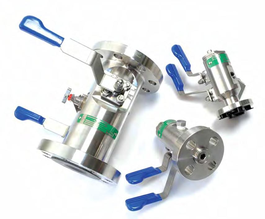
Parker Hannifin’s response to the demand for reduction in leakage paths has been the combination of primary and secondary valves into one compact unit. The combining of piping and instrument valves into a single unit has benefitted various markets. We now offer a range of Ultra-Low Emission products which meet class ‘A’ or class ‘B’ levels of ISO 15848 standard for Ultra-Low emissions, as required.
Parker Hannifin can offer the unique combination of double block and bleed valve systems together with integral fittings, both being designed and produced by one company. Selection of this combination results in the elimination of taper thread connections and the need for thread sealant. For more information on leak path reductions and how to combine connections and valves into one unit, please contact us.
Contents
Page 2 Introduction.
Page 3 Application illustrations.
Page 4 Ball valve specification.
Page 5 Outside screw and yoke (O.S.&Y.) valve specification.
Page 6 Globe style needle valve specification.
Page 7 Bolted bonnet.
Page 8/11 Monoflange (MF) manifolds.
Page 12/15 ANSI/ASME B31.1 Monoflange manifolds.
Page 16/22 Pro-Bloc (PB) manifolds.
Page 23/24 Meeting the ISO Standard
Page 25/31 Ultra-Low Emission solutions
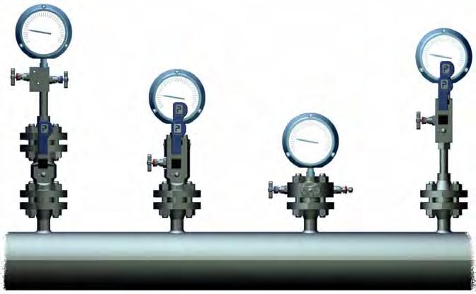
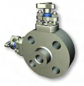
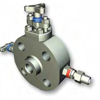
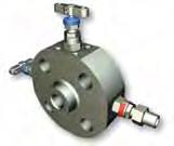
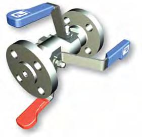
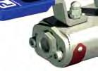
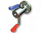
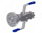
Primary, secondary and vent valve applications and installations
Solutions
Parker Hannifin offers the unique solution by incorporating primary and secondary valve systems into one complete block. In addition traditional instrument taper thread connections can be totally eliminated resulting in systems being free of thread sealant contamination.
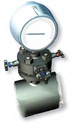
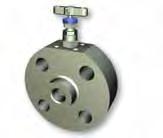
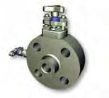
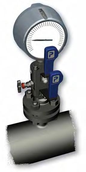
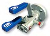
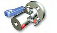
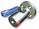
Conventional Installation [1]
• A welded flange, connected to a primary ANSI class isolating valve. The primary valve will be connected to a secondary instrument valve. A pressure gauge or transmitter will then be installed downstream of the instrument valve

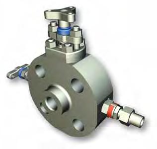
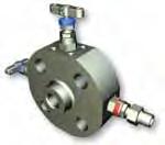
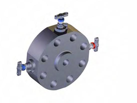
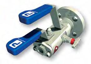
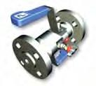
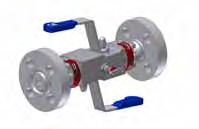
Parker Pro-Bloc® [2]
• A one-piece integral forging incorporating up to 3 ball valves or mixture of ball and needle design.


• Improved safety: leak paths reduced by up to 60%
• Reduced costs: installation and component costs reduced by up to 70%
• Reduced weight: by up to 80%
• Reduced susceptibility to problems caused by vibration. See pages 23-31 for standard and Ultra-Low Emission products.
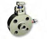
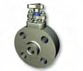
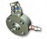
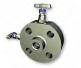
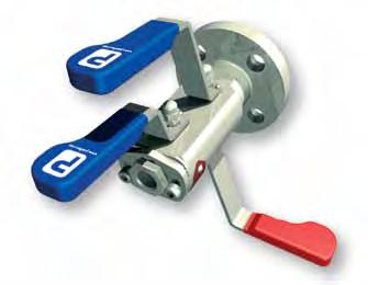
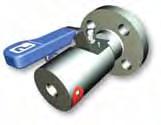
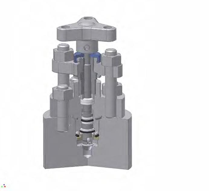
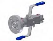
Parker Monoflange [3]
• More compact than Pro-Bloc , adding further space and weight saving possibilities
• Improved safety: leak paths reduced by up to 60%, less susceptibility to vibration
• Reduced costs: installation and component costs reduced by up to 80%
• Reduced weight: by up to 85%
See pages 11-16 for standard and pages 23-31 for Ultra-Low Emission products
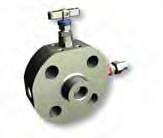
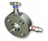
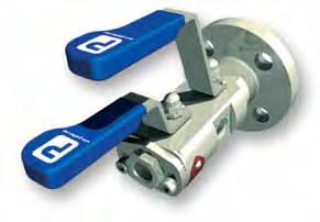
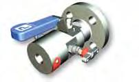
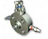
Parker Hi-Pro Manifolds [4]
• Enables the user to continue to use traditional NPT threaded connections and at the same time utilise the double block and bleed principals Available in several combinations of ball and needle valves

Full details can be found in CAT 4190 HBM
Conventional [1] Hi-Pro [4]
Pro-Bloc [2]
Monoflange [3]
Design codes
All Parker Hannifin double block and bleed designs comply with the following codes:
• ANSI/ASME B16.34 (Designed to meet the pressure and temperature requirements)

• ANSI/ASME B1.20.1 (Threads)
• ANSI/ASME B16.5 (Dimensions)


• BS6755 PART 2/API 607 (Fire safe designed to meet the requirements and verified by internal testing)
• ISO 15848 for Ultra-Low emissions
• B31.1

2
3
Flanged Products Flanged Products
650mm 330mm 170mm 500mm Typical heights
Typical weights 35 kgs 7 kgs 5 kgs 3 kgs
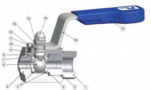
Ball valve specification

Specifications
• 316 Stainless steel construction
• Maximum cold working pressure rating 6,000 psig (414 barg) with P.T.F.E. seats*
• Temperature rating PTFE seats -54˚C to +204˚C (-65˚F to +400˚F)*
• Maximum cold working pressure rating 10,000 psig (689 barg) with PEEK seats*
• Temperature rating PEEK seats -54˚C to +232˚C (-65˚F to +450˚F)* *always refer to P/T graph
Features
• Two piece body design - minimal leakage paths
• 4:1 Pressure boundary designed safety factor
• Designed to comply with requirements of ANSI/ASME B16.34 where applicable
• Bi-directional
• PEEK and PTFE standard ball seat materials
• PTFE and Graphoil gland packings
• Bubble tight shutoff.
• Floating ball principal with dynamic response seats featuring inherent self relief
• Anti blowout stem
• Integral compression ends available eliminating taper threads and thread sealants
• Low torque operation
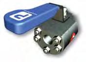
• Quarter turn positive stop handle with ergonomically designed protective sleeve
• Full hydrostatic and low pressure air tested
• Connector thread environmentally sealed
• Anti static
• Firesafe designed to meet BS6755 Part 2/ API 607, (optional)
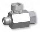
Part description
Spanner actuation
Outside screw and yoke (O.S.&Y.) needle valve
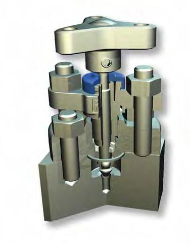
Features
• Externally adjustable gland
• P.T.F.E. or Graphite packing for bubble tight sealing
• Self centering crimped needle tip for bubble tight shut off and repeatability
• Available in 316, Monel, Duplex, Super Duplex, Hasteloy, Inconel, Incoloy, 6Mo, Carbon Steel, other materials on application
• Stainless steel as standard
• Optional wetted parts in a variety of exotic materials
• Firesafe certified to BS6755 part 2/ API 607
• Pressure rating up to 10,000 psig (690 barg)
• Temperature -54°C to 538°C (-65°F to 1000°F)
• Body to bonnet flange gasket for 100% atmospheric seal
• Back stopped spindle for blow out prevention, and minimum atmospheric leakage
• Rolled spindle operating threads
• Independent spindle thread bush with maximum female thread interface
• Colour coded close contact dust cap and function label for easy identification
• Optional: NACE compliance, heat code trace certification, oxygen clean
Performance Data Pressure vs temperature
Products Flanged Products 5
4 Flanged
Optional bolted end connector Handle locking Item Description 1 End connector 2 E-seal™ 3 Sealing washer 4 Seats 5 Body 6 Ball 7 Anti blowout stem 8 Thrust Seal 9 Gland packing 10 Upper gland packing 11 Thrust bush 12 Stop pin 13 Thrust bush 14 Lock nut 15 Locking dome nut 16 Handle 17 Handle grip
* See catalogue 4190-HBV Hi-Pro Ball Valve for High Performance Process Isolation WARNING When selecting products for specific applications users should refer to our notice at the bottom of page 13.
Pressure
10,000 (690) 8,000 (552) 6,000
4,000
2,000
0 Pressure psig (barg) A - A Graphite packing A - B PTFE packing B - B 6000 psig (414 barg) standard PTFE packing B - C 6000 psig (414 barg) standard Graphite packing B - B PEEK tip C - E PCTFE tip Temperature °C (°F) B E B CA Item Description 1 Body 2 Tip 3 Joint seal 4 Packing 5 Thrust bush 6 Stem 7 Gland adjuster 8 Bridge nuts 9 Bonnet-bridge studding 10 Handle 11 Grub screw 12 Dust cap 13 Bridge 14 Bonnet 15 Body-bonnet studding 16 Stud nuts 9 10 11 13 16 14 15 WARNING When selecting products for specific applications users should refer to our notice at the bottom of page 13. ! ! 12 1 2 3 4 5 6 7 8
Part description
vs temperature
(413)
(275)
(138)
Monoflange (MF) manifolds
Purpose
This manifold range is designed to replace conventional multiple-valve installations currently in use for interface with pressure measuring systems. By combining customer specified valves into a single manifold, the number of leak paths is considerably reduced and the mass of the system is lowered reducing the stresses from loading and vibration. The result of which substantially improves installation and operational safety factors. Reduction in leakage path connections together with a one-piece solution also provides positive installation cost savings. Suitable for Ultra-Low Emission requirements.
Key advantages of Parker Monoflanges
• Strong construction produced from one piece grain flow controlled forged body
• Various flow and valve configurations available allowing true flexibility to meet all customer requirements
• Variety of flange sizes and outlet connections
• Standard materials of Carbon Steel A105, Low Temperature Carbon Steel A350 LF2, Stainless Steel A182-F316 and Duplex Stainless Steel A182-F51
• Optional materials include Super Duplex, Monel, Hastelloy, 6Mo, Incoloy 625
• Incorporation of standard ‘H’ series needle valve technology and state of the art O.S.&Y. design
• 4mm Needle valve orifice
• Ergonomically designed operating handles with low torque function
• Full range of customer retro fit handle options
• User friendly part number and specification construction system
• Customised designs welcome
• Available to meet ISO 15848, Class A
Instrument outlet connections
One of the unique features Parker can offer users which can further enhance safety factors is the incorporation of single or twin ferrule compression fittings as an integral part of the outlet connection. Installation of the instrument which require remote positioning will be interconnected using conventional tube and fittings, whilst NPT taper threads are accepted as a standard their use involves some form of thread sealant which adds to the complication of instrument performance through contamination within the system. Avoiding these taper thread connections wherever possible reduces this contaminant risk and Parker, being a leading manufacturer of compression type of fittings (which requires no sealant mediums), can incorporate them in the outlet connection, totally eliminating the contamination risk.
Monoflange features
• 1/2” to 2” N.B. Flanges (15 to 50 DN)
• ANSI B16.5 150 to 2500 flange class and API 10,000
• 1/2-14 NPT (female) standard outlet
• 1/4-18 NPT (female) standard vent
• Variety of optional end connection sizes and thread forms including tube connections 1/2”/12mm diameter
• Standard materials of construction: Stainless steel ASTM A182 F316/F316L, Carbon steel ASTM A350 LF2/A105, Duplex ASTM A182 F51
• Optional materials include Super Duplex, Monel, Hastelloy, 6Mo, Incoloy
• Combined needle and O.S.&Y. valves available
• Instrument connections A-LOK inverted available
• Raised face and ring type joint flange face styles
• One-piece forged construction flange as standard
• H needle design with retro fit handle options
• Optional fire safe designed (and tested) to meet BS6755 part 2/API 607
• Pressure boundary designs calculated to ASME VIII Div. 1 and verified by testing
• 4:1 Factor of Safety
• Heat code traceable material to EN10204.3.1
• Bubble tight shut off valve seats 17-4 PH tips standard
• Optional PEEK tips available
• Colour coded functional valves
• Optional locking and anti tamper devices for all valve types available
• NACE MR 0175/ISO 15156 compliant material available on request
• Permanent marked body with full order and specification details
• Available with various non-threaded connections, please contact us
Standard specification:
Outlet - 1/2” FNPT
Vent - plugged 1/4” FNPT Seat - metal to metal Packing - PTFE
8 Flanged Products Flanged Products 9
PROCESS PROCESS INSTRUMENT OUTLETS BLANKED OUTLETS
MFY100 MFY110 MFY140 MFH100 MFH110
HORIZONTAL VERTICAL OPTION (ONLY AVAILABLE WITH TWIN OUTLET)
Monoflange (MF) manifold selection and part number construction - made easy
Select the style of Monoflange from the choice of arrangements below noting the complete MF reference If the style or arrangement is not shown below please provide full description and specification.
Block bleed block
1st Isolate: O.S.&Y.
2nd Isolate: Needle Vent: Needle
* *
1st Isolate: Needle
2nd Isolate: Needle
3. Flange details
Flange Flange Face Style Flange Class Size
Block & bleed
1st Isolate: Needle
Vent: Needle
Block & bleed
1st Isolate: O.S.&Y.
Vent: Needle
8 = 1/2” F = Raised Face Spiral 150 = 150 12 = 3/4” T = Ring Type Joint 300 = 300 16 = 1” 600 = 600 24 = 1 1/2” 900 = 900 32 = 2” 1500 = 1500 API specify separately 2500 = 2500 DIN see page 20 136 = 150/300/ *1/2” flange size only 1360 = 600
8. Condition F Firesafe design (primary only - O.S.&Y. needle valve)
Block & bleed
1st Isolate: Needle Vent: Needle
Block & bleed
1st Isolate: O.S.&Y. Vent: Needle
Double block
1st Isolate: O.S.&Y.
2nd Isolate: Needle.
IMPORTANT NOTES
Valve handle operating options
1st
u For dual outlets specify MF*105. s For dual outlets specify MF*115.
For flange to flange variants replace MF*1** with MF*2**. For bleed port only specify MF*160.
Please note vent valve is not anti-tamper as standard.
Single block
1st Isolate: O.S.&Y.
All non wetted parts will be supplied in standard stainless steel for exotic materials. For carbon steel construction trim materials will be supplied in stainless steel.
Ring type joints (T) CANNOT be supplied for 1/2” & 3/4” class 150 flanges. St. St. grades 302 and 304 are NOT used in the construction of any of these products.
For customer specific options not covered here engineering will allocate a part number at quotation stage.
Certification requirements and customer specifications MUST be provided at enquiry and order stage.
For API flange requirements full details must be specified separately.
Part number example MFY100B32T2500A3F Monoflange - Double Block and Bleed - Block (O.S.&Y.) Bleed (Needle) Block (Needle) (MFY100) - 316 St. St. construction (B) - 2” Pipe flange, Ring type joint, class 2500 (32T2500) - 1/2” female NPT outlet - 1/4” Female NPT vent - Anti-tamper vent (A3) - Firesafe design and certified (F), valves fitted with PTFE packing, metal seated 17-4PH st.st. tips.
10
Products Flanged Products 11
Flanged
s u s Example MFY100 B 32T2500 8F V6F A3 F
u
4. Outlet style (1/2” FNPT is standard NO part designator needed) Size Connection Style 40M = 1/4” F = Female NPT Thread 60M = 3/8” M = Male NPT Thread 80M = 1/2” A = A-LOK (inverted M60 = 6mm A = only) M10 = 10mm G = Swivel gauge M12 = 12mm G = adaptor 1/2” G = NPTF (fitted) 1. Monoflange part number Insert from page 10 * }
WARNING When selecting products for specific applications users should refer to our notice at the bottom of page 27.
block
Double
block
1st Isolate: Needle 2nd Isolate: Needle Single
Isolate: Needle
bleed
Block block
Vent: Needle Block block bleed 1st Isolate: O.S.&Y. 2nd
Needle Vent: Needle Block bleed block 1st Isolate: Needle 2nd Isolate: Needle Vent: Needle MFH100 MFY100 MFY110 MFY120 MFY130 MFY140 MFY150 MFH150 MFH140 MFH130 MFH120 MFH110 ! 2. Material A Carbon Steel ASTM A105 B Stainless Steel ASTM A182-F316 D Monel M400 E Duplex ASTM A182-F51 F Super Duplex ASTM A182-F53/F55 G Hastelloy C-276 H Low Temp. C. St. ASTM A350 LF2 K 6Mo M Inconel 625 5. Plugged vent (1/4” FNPT is standard NO part designator needed) Size V6 = 3/8” FNPT V8 = 1/2” FNPT 6. Valve packing and seat materials * PTFE Packing * Needle tip 17-4PH St. St. 3 Graphoil (fitted as standard when fire safe design is specified) PN PEEK Needle tip all valves
fire safe only) * fitted as standard no part NO designator required.
R*
Y*
valves
Padlocks not supplied
Isolate:
(non
7.
A* Anti tamper L* Padlock handle locking
Regulating tip (“H” series needle valve only)
O.S.&Y.
* Insert valve number 1 = primary, 2 = secondary, 3 = vent, 4 = all.
N
NACE Combine designators as required Please Note: Certification requirements and customer specifications MUST be provided at enquiry and order stage.
Monoflange manifolds compliant with ANSI B31.1
Purpose
This manifold range is designed to replace conventional multiple-valve installations currently in use for interface with pressure measuring systems. By combining customer specified valves into a single manifold, the number of leak paths is considerably reduced and the mass of the system is lowered reducing the stresses from loading and vibration. The result of which substantially improves installation and operational safety factors. Reduction in leakage path connections together with a one-piece solution also provides positive installation cost savings.
Key advantages of Parker Monoflanges
• Strong construction produced from one piece grain flow controlled forged body
• Various flow and valve configurations available allowing true flexibility to meet all customer requirements
• Variety of flange sizes and outlet connections
• Incorporation of ‘HPP’ series needle valve technology
• 4mm Needle valve orifice
• Ergonomically designed operating handles with low torque function
• Full range of customer retro fit handle options
• User friendly part number and specification construction system
• Customised designs welcome
Monoflange features
• 1/2” to 2” N.B. Flanges (15 to 50 DN)
• ANSI B16.5 150 to 2500 flange class
• 1/2-14 NPT (female) standard outlet
• 1/4-18 NPT (female) standard vent
• Variety of optional end connection sizes and thread forms including tube connections 1/2”/12mm diameter
• Standard materials of construction: Stainless steel ASTM A182 F316/F316L, Carbon steel ASTM A350 LF2/A105
• Instrument connections A-LOK inverted available
• Raised face and ring type joint flange face styles
• One-piece forged construction flange as standard
• Graphite packing to meet full pressure/temperature requirements of ANSI B31.1 materials
• Pressure boundary designs calculated to ANSI B31.1
• 4:1 Factor of Safety
• Heat code traceable material to EN10204.3.1
• Bubble tight shut off valve seats 17-4 PH tips standard
• Colour coded functional valves
• Optional locking and anti tamper devices for all valve types available
• NACE MR 0175/ISO 15156 compliant material available on request
• Permanent marked body with full order and specification details
• Available with various non-threaded connections, please contact us
Standard specification: Outlet - 1/2” FNPT Vent - plugged 1/4” FNPT Seat - metal to metal Packing - PTFE
Features
Pressure vs temperature
• All valves are graphite packed for high temperature service
Instrument outlet connections
One of the unique features Parker can offer users which can further enhance safety factors is the incorporation of single or twin ferrule compression fittings as an integral part of the outlet connection.
Installation of the instrument which require remote positioning will be interconnected using conventional tube and fittings, whilst NPT taper threads are accepted as a standard their use involves some form of thread sealant which adds to the complication of instrument performance through contamination within the system.
Avoiding these taper thread connections wherever possible reduces this contaminant risk and Parker, being a leading manufacturer of compression type of fittings (which requires no sealant mediums), can incorporate them in the outlet connection, totally eliminating the contamination risk.
(483) 6000 (414) 5000 (345) 4000 (276) 3000 (207) 2000 (138) 1000 (69) 0
• Non rotating, hard stem tip with metal to metal seating for bubble tight shut-off
• Back seat design
• Blow-out proof stem
• Pressures & temperatures in accordance with ASME class 2500
• Patented Tru-Lok safety bonnet locking device prevents accidental removal
• Standard orifice 4mm (Cv 0.35) Specific pressure / temperature performance
bar @ 538°C)
12 Flanged Products Flanged Products 13
SS
316
6000 psig @ 100°F (414 bar @ 38°C) 2915 psig @ 1000°F (201
0 100 200 300 400 500 600 700 800 900 1000
(-18) (38)
WARNING FAILURE IMPROPER SELECTION OR IMPROPER USE OF THE PRODUCTS AND/OR SYSTEMS DESCRIBED HEREIN OR RELATED ITEMS CAN CAUSE DEATH, PERSONAL INJURY AND PROPERTY DAMAGE This document and other information from Parker Hannifin Corporation, its subsidiaries and authorized distributors provide product and/or system options for further investigation by users having technical expertise. It is important that you analyze all aspects of your application and review the information concerning the product or system in the current product catalog. Due to the variety of operating conditions and applications for these products or systems, the user, through its own analysis and testing, is solely responsible for making the final selection of the products and systems and assuring that all performance, safety and warning requirements of the application are met. The products described herein, including without limitation, product features, specifications, designs, availability and pricing, are subject to change by Parker Hannifin Corporation and its subsidiaries at any time without notice. Offer of Sale The items described in this document are hereby offered for sale by Parker Hannifin Corporation, its subsidiaries or its authorized distributors. Any Order accepted by Parker Hannifin will be subject to our terms and conditions of sale, copy available on request. WARNING ! WARNING When selecting products for specific applications users should refer to our notice below. !
7000
Temperature °F (°C) Pressure psi (bar)
(93) (149) (204) (260) (316) (371) (427) (482) (538)
ANSI B31.1 compliant manifold selection and part number construction - made easy
Select the style of Monoflange from the choice of arrangements below noting the complete reference.
If the style or arrangement is not shown below please provide full description and specification.
Block bleed block
1st Isolate: Needle
Block & bleed
*
2nd Isolate: Needle Vent: Needle
PPMFH100
s
Block block bleed
1st Isolate: Needle
2nd Isolate: Needle Vent: Needle
1st Isolate: Needle Vent: Needle
PPMFH130
Example PPMFH100 B 32T2500 8F V6F 3 A3 N
1. Monoflange part number
Insert from page 14
2. Material
A Carbon Steel ASTM A105 B Stainless Steel ASTM A182-F316 G Hastelloy C-276 H Low Temp. C. St. ASTM A350 LF2
3. Flange details
Flange Flange Face Style Flange Class
8. Condition N NACE
Combine designators as required
Please Note: Certification requirements and customer specifications MUST be provided at enquiry and order stage.
Double block
1st Isolate: Needle
2nd Isolate: Needle
Size
8 = 1/2” F = Raised Face Spiral 1500= 150 12 = 3/4” T = Ring Type Joint 3000= 300 16 = 1” 6000= 600 24 = 1 1/2” 9000= 900 32 = 2” 1500 = 1500 API specify separately 2500 = 2500 DIN see page 20 136 = 150/300/ *1/2” flange size only 1360 = 600 }
*
Block & bleed
1st Isolate: Needle Vent: Needle
PPMFH120
u For dual outlets specify PPMFH105. s For dual outlets specify PPMFH115. For flange to flange variants replace PPMFH1** with PPMFH2**.
For bleed port only specify PPMFH160.
Please note vent valve is not anti-tamper as standard.
Single block
1st Isolate: Needle PPMFH150
4. Outlet style (1/2” FNPT is standard NO part designator needed)
Size Connection Style
40M = 1/4” F = Female NPT Thread 60M = 3/8” M = Male NPT Thread 80M = 1/2” A = A-LOK (inverted only) M60 = 6mm G = Swivel gauge A = M10 = 10mm M12 = 12mm
adaptor 1/2” NPTF (fitted)
7.
Valve handle operating options
A* Anti tamper
L* Padlock handle locking
R* Regulating tip (“H” series needle valve only)
* Insert valve number 1 = primary, 2 = secondary, 3 = vent, 4 = all. Padlocks not supplied
5. Plugged vent (1/4” FNPT is standard NO part designator needed)
Size V6 = 3/8” FNPT V8 = 1/2” FNPT
6. Valve packing
3 Graphoil (standard)
WARNING
When selecting products for specific applications users should refer to our notice at the bottom of page 27.
IMPORTANT NOTES
All non wetted parts will be supplied in standard stainless steel for exotic materials. For carbon steel construction trim materials will be supplied in stainless steel.
Ring type joints (T) CANNOT be supplied for 1/2” & 3/4” class 150 flanges.
St. St. grades 302 and 304 are NOT used in the construction of any of these products.
For customer specific options not covered here engineering will allocate a part number at quotation stage.
Certification requirements and customer specifications MUST be provided at enquiry and order stage.
Part number example PPMFH100B32T25003A3 Monoflange - Double Block and Bleed - Block (Needle) Bleed (Needle) Block (Needle) (PPMFH100) - 316 St. St. construction (B) - 2” Pipe flange, Ring type joint, class 2500 (32T2500) - 1/2” female NPT outlet - 1/4” Female
NPT vent - Graphite Packing (3) Anti-tamper vent (A3) metal seated 17-4PH st.st. tips.
14
15
Flanged Products Flanged Products
u
PPMFH140 PPMFH110 !
Pro-Bloc® (PB) Manifolds
Purpose
This manifold range is designed to replace conventional multiple-valve installations currently in use for interface with pressure measuring systems. By combining customer specified valves into a single manifold, the number of leak paths is considerably reduced and the mass of the system is lowered reducing the stresses from loading and vibration. The result of which substantially improves installation and operational safety factors. Reduction in leakage path connections together with a one-piece solution also provides positive installation cost savings.
Key advantages of Parker Pro-Bloc®
• Strong construction produced from one piece grain flow controlled forged body
• Various flow and valve configurations available allowing true flexibility to meet all customer requirements
• Single flange, double flange or triple flange configurations available
• Standard materials of Carbon Steel A105, Low Temperature Carbon Steel A350 LF2, Stainless Steel A182-F316 and Duplex Stainless Steel A182-F51
• Optional materials include Super Duplex, Monel, Hastelloy, 6Mo, Incoloy 625
• Incorporation of standard Hi-Pro ball valve and “H” series needle valve technology
• 10mm/15mm/20mm/25mm full bore valve design
• Ergonomically designed operating handles with low torque function
• User friendly part number and specification construction system
• Optional integral A-LOK /CPI outlet connection
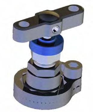
• Parker Tru-loc (patent pending) safety system
Tru-Loc
™
Mechanical Sealed End Connection
Designed specifically for Pro-Bloc end connection security. Extensive tests have proved that end connections locked with the Tru-Loc™ (PP) end connector locking mechanism give 100% security and prevent end connector movement when disconnecting instruments or connectors. This ensures that the Ball Seat is securely positioned at all times.
Instrument outlet connections
One of the unique features Parker can offer users which can further enhance safety factors is the incorporation of single or twin ferrule compression fittings as an integral part of the outlet connection. Installation of the instrument which require remote positioning will be interconnected using conventional tube and compression fittings, whilst NPT taper threads are accepted as a standard their use involves some form of thread sealant which adds to the complication of instrument performance through contamination within the system. Avoiding these taper thread connections wherever possible reduces this contaminant risk and Parker, being a leading manufacturer of compression type of fittings (which requires no sealant mediums), can incorporate them in the outlet connection, totally eliminating the contamination risk.
Pro-Bloc® features
• 1/2” to 3” N.B. Flanges (15 to 50 DN)
• ANSI B16.5 150 to 2500 flange class and API 10,000
• 10mm/15mm/20mm/25mm full bore valve design
• 1/2”-14 to 1”-11.5 NPT (female) standard outlet (depending on bore size)
PB*100
• 1/2” NPT (female) standard vent
• Variety of optional end connection sizes and thread forms including tube connections up to 1”/25mm diameter (depending on bore size)
• Standard materials of construction: Stainless steel ASTM A182 F316/F316L, Carbon steel ASTM A350 LF2/A105, Duplex ASTM A182 F51
• Optional materials on request
• Instrument connections A-LOK /CPI available
• Raised face and ring type joint flange face styles
PB*120
• One-piece forged construction flange as standard
• Optional fire safe designed (and tested) to meet BS 6755 Part 2/API 607
• 316 stainless steel handles and trim as standard to reduce the risk of corrosion
• Designed to meet the pressure and temperature requirements of ASME/ANSI B16.34/B16.5
• Pressure boundary designs calculated to ASME VIII Div 1 and verified by testing
• 4:1 Factor of Safety
• Heat code traceable material to EN10204.3.1
• Bubble tight shut off
• Colour coded functional valves
PB*160
• Optional locking and anti tamper devices for all valve types available
• Positive lever stop
• NACE MR 0175/ISO 15156 compliance available on request
• Large user friendly handles
• Permanent affixed reference label
• O.S.&Y. and “H” series needle valves can be combined with ball valves
Standard specification flange x screw: Outlet - FNPT; Vent - 1/2” FNPT plugged; Ball seats. P.T.F.E.; Needle seats, metal/metal 17-4 PH St. St.; P.T.F.E. packing all valves.
16 Flanged Products Flanged Products 17
PB*220
NACE Combine designators as required Please Note: Certification requirements and customer specifications MUST be provided at enquiry and order stage. 7. Valve
handle operating options
A* Anti tamper (Needle Valve only)
L* Padlock handle locking R* Regulating tip (“H” series Needle Valve only)
S* Spanner actuated (Ball Valve only)


Y* O.S.&Y. Needle Valve
* Insert valve number 1 = primary, 2 = secondary, 3 = vent, 4 = all. Padlocks not supplied
Note: Firesafe needle valve with locking device NOT available
firesafe only)
18 Flanged Products Flanged Products 19 3. Flange details Flange Flange Face Style Flange Class Size ‡8 =
F = Raised Face Spiral
1500 ‡12 =
T = Ring Type Joint 300
3000 ‡16 =
6000 =
‡24 =
900
‡32 = 2” 1500
‡48 =
bore only) 2500
‡API specify separately ‡DIN See page 20 • Block bleed block
PBY*10 Block bleed block
Vent:
PB**00 Block & bleed
PB**30 Single isolate. specify
Pro-Bloc® (PB) manifold selection and part number construction - made easy Select the style of Pro-Bloc® from the choice of arrangements below noting the complete PB reference. Example PB Y 1 00 B 32T2500 8F V6F AT F 1. Ball valve bore size Y =
X =
W =
V =
} ‡ Certain flange/bore size combinations not available - consult factory Single piece forging flange x screw Single piece forging flange x flange
bleed block
1/2”
1500 =
3/4”
0 =
1”
6000
1 1/2”
0 = 9000
= 1500
3” (25mm
= 2500
1st Isolate: Ball 2nd Isolate: Needle Vent: Needle
1st Isolate: Ball 2nd Isolate: Ball
Needle
1st Isolate: Ball Vent: Needle
PB*165, PB*265.
10mm
15mm
20mm
25mm
Block
1st Isolate: Ball 2nd Isolate: Ball Vent: Ball Block & bleed 1st Isolate: Ball Vent: Ball Double block
1st Isolate: Ball 2nd Isolate: Needle Double block
PB*1** PB*2** PB**60 PBY*50 PB**40 PB**20 2.
A
B
D
E
G
K
L
M
625 5. Plugged vent (1/2” NPTF as standard NO part designator needed)
N
1st Isolate: Ball 2nd Isolate: Ball
Material
Carbon Steel ASTM A105
Stainless Steel ASTM A182-F316
Monel M400
Duplex ASTM A182-F51 F Super Duplex ASTM A182-F53/F55
Hastelloy C-276 H Low Temp. C. St. ASTM A350 LF2
6Mo
825
Inconel
6. Packing, seat and construction options * PTFE Packing * PTFE Ball seats * Needle tip 17-4PH St. St. PK PEEK Ball and needle seating PB PEEK Ball seats PN PEEK Needle tip (non
BC Bolted construction connection * fitted as standard no part NO designator required. 8. Condition F Firesafe design
4. Outlet style (each bore size has its own standard size female NPT outletthe standard does not require this field to be completed) Standard outlets (female NPT) 10mm bore = 1/2” 15mm bore = 1/2” 20mm bore = 3/4” 25mm bore = 1” For optional outlets see page 20 Style Arrangement Modular construction flange x screw Modular construction flange x flange PB*5** PB*6** For style see page 18 section ‘Style’ For arrangement see page 18 section ‘Arrangement’ • Only available with 10mm bore ball valve. •
Other flange detail options
(reference Box 3 flange details pages 11, 15, 19, 29 & 31)
3. Flange details API 6A / ISO 10423* (Dimensionally compliant only)
Flange Flange Size Rating
29 = 1 13/16”
Other outlet options (reference Box 4 outlet style pages 11, 15, 19, 29 & 31)
4. Optional outlets
Size Connection Style
14 = 1/4”
12K = 2000 psig0
33 = 2 1/16” 13K = 3000 psig0
1 41 = 2 9/16” 15K = 5000 psig0
10K = 10000 psig (not available for
Ultra-Low emission products).
* Only available with 10mm bore (PBY) and Monoflange products.
3. Flange details DIN
Flange Flange Size Class
DN10 PN6
DN15 PN10
DN20 PN16
DN25 PN40
DN32 PN100
DN40 DN50
F = Female NPT
16 = 3/8” M = Male NPT
18 = 1/2” A = A-LOK 10 = 5/8” Z = CPI 12 = 3/4” G = Swivel gauge adaptor 14 = 7/8” 1/2” Female NPT (fitted) 16 = 1”/0
0M6 = 06mm M10 = 10mm M12 = 12mm M14 = 14mm M15 = 15mm M16 = 16mm M18 = 18mm M20 = 20mm M22 = 22mm M25 = 25mm
Note: Contact factory for bore size/outlet connection combinations
Pro-Bloc® (PB) Manifolds
Pro-Bloc® for sampling applications (10mm + 15mm bore only)
This manifold range is designed to replace conventional multiple-valve installations where sampling of the process stream is required. This design has been developed to remove a sample directly from the process stream at full system pressure. All of the options and configurations shown within the standard Pro-Bloc® range can be offered for sampling service by the addition of a customised sampling probe which extends from the pipe flange into the process stream. Also available to suit ISO15848 Class ‘A’ Ultra-Low emission standard.
IMPORTANT NOTES
All non wetted parts will be supplied in standard stainless steel for exotic materials. For carbon steel construction trim materials will be supplied in stainless steel.
For flange to flange construction when the required flanges are different sizes then specify both sizes in section 3 example: 1st flange 1” pipe (16), raised face (F), class 900 (900), 2nd flange 1/2” (8), raised face (F), class 900 (900) insert: 16F9008F900. Consult factory for available combinations. Ring type joints (T) CANNOT be supplied for 1/2” & 3/4” class 150 flanges. St. St. grades 302 and 304 are NOT used in the construction of any of these products.
For customer specific options not covered here engineering will allocate a part number at quotation stage. Certification requirements and customer specifications MUST be provided at enquiry and order stage. For API flange requirements full details must be specified separately.
Part number example FEPBY100B32T2500F Ultra-Low Emission Pro-Bloc - Flange by screw - Double Block and Bleed - Block (Ball) Bleed (Needle) Block (Ball) (FEPBY100) - 316 St. St. construction (B) - 2” Pipe flange, Ring type joint, class 2500 (32T2500) - 1/2” female NPT outlet - 1/2” Female NPT vent - Firesafe design and certified (F), all valves PTFE packed, ball seats PTFE, needle valve metal seated 17-4PH st.st. tips.
Pro-Bloc® for sampling applications - part numbering
In order to specify the addition of a sampling probe to your Pro-Bloc simply add an “S” to the beginning of the part number i.e. SPB or FESPB… The probe length in “mm” must be added to the end of the part number, see below. Due to the internal bore size of standard ASME flanges probes can only be installed on a range of flanges - please see the attached table.
Bore Flange range
10mm Size 1” and above, ASME flanges up to class 2500.
15mm Size 1 1/2” and above, ASME flanges up to class 2500.
20mm Not available
25mm Not available
The probe length must be specified from the raised face to the end of the probe in mm, to the nearest mm. Probes are supplied to suit the insertion length required by the pipeline and thus must be specified by the customer.
A wide variety of end preparations and support collars are available on request. Probe strength wake frequency calculations can be carried out against pipeline flow rates on request. In the event of the required valve configuration not be shown please do not hesitate to contact the factory as Parker Hannifin IPD offer bespoke customer solutions.
20
21
Flanged Products Flanged Products
When selecting products for specific applications users should refer to our notice at the bottom of page 19.
WARNING
Pro-Bloc® (PB) Manifolds Meeting the ISO Standard
Pro-Bloc® for injection applications (10mm + 15mm bore only)
This manifold range is designed to replace conventional multiple-valve installations where injection into the process stream is required. This design has been developed to inject directly into the process stream at full system pressure. All of the options and configurations shown within the standard Pro-Bloc range can be offered for injection service by the addition of a customised injection probe which extends from the pipe flange into the process stream. Pro-Bloc’s for injection applications include an injection probe which enables the fluid to be injected directly into the process stream and a high integrity full bore non-return valve to eliminate the risk of back flow out of the process stream. Also available to meet ISO15848 Class ‘A’ Ultra-Low emission standard.
From October 2007 all UK processing plants and power stations will have to comply with the EU’s IPPC directive 96/61/EC. In essence, the IPPC Directive is about minimising pollution from various industrial sources throughout the European Union. An important part of this legislation is reducing Ultra-Low emissions, which will have significant consequences for all processes. According to the IPPS all plants and factories which fail to comply with the standards set by the directive may be closed from this point.
To put the scale of the challenge into perspective, a typical European refinery loses between 600 and 10,000 tonnes of emissions per annum. Around 70% of these losses are estimated to be caused by plant equipment such as pipe flanges, pumps, valves and vessels. Leakage from valves is often the biggest culprit, reportedly accounting for around 50% of the Ultra-Low emissions within the chemical and petrochemical industries.
Pro-Bloc® for injection applicationspart numbering
In order to specify the addition of an injection probe and non-return valve to your Pro-Bloc® simply add a ‘J’ to the beginning of the part number i.e. JPB or FEJPB… The probe length in “mm” must be added to the end of the part number, see below. Due to the internal bore size of standard ASME flanges probes can only be installed on a range of flanges - please see the table in the sampling Pro-Bloc® section (previous page).
The probe length must be specified from the raised face to the end of the probe in mm, to the nearest mm. Probes are supplied to suit the insertion length required by the pipeline and thus must be specified by the customer.
A wide variety of end preparations and support collars are available on request.
Probe strength wake frequency calculations can be carried out against pipeline flow rates on request.
Hi-Check non-return valve
This high integrity full bore non-return valve eliminates the risk of back flow out of the process stream. The design utilises a spring loaded poppet to ensure leak proof performance. The Hi-Check Non Return Valve is designed for higher flow and low pressure drop across the valve - having a larger through bore than most other manufacturers equivalent product.

As standard a viton seal will be supplied with a ‘crack’ pressure of 10 psig. A wide variety of seat materials and crack pressures are available on request.
In the event of the required valve configuration not being shown please do not hesitate to contact the factory as Parker Hannifin IPD offer bespoke customer solutions. See Catalogue 4190-CV for more details.
Irrespective of the environmental impact, there is a tremendous financial burden on industry because it represents a huge loss of product, and cause of plant inefficiency. However, the true costs to industry are not always appreciated, as many of the costs associated with Ultra-Low emissions are hidden. Such as labour and materials to repair leaks, wasted energy, environmental fines and clean up costs, lost sales due to a poor green image, claims for personal injury and more. In this way, reducing Ultra-Low emissions not only protects the environment, but can save companies time and money.
With the above in mind, the legislation introduces a concept of Best Available Technique (BAT), urging plants to find the best available solution for reducing Ultra-Low emissions throughout the process, from areas such as design, product selection, fitting and fitter training, to maintenance, site monitoring, and so on.
With regard to the design and site monitoring of UltraLow emissions ISO 15848 parts 1 and 2 have been developed respectively.

Part 1 covers the classification system and qualification procedure for type testing of valves. The standard specifies three tightness classes of leakage with respect to stem sealing diameter. These classes are class A, B and C. Class A having the smallest environmental leakage. Each class level is one hundred fold lower than the class above i.e. a class B product may have a leakage of 100 times that of a class A product. The standard also specifies the duty that the valve has been tested to.
Parker Hannifin is now able to offer our full range of flanged products with a class A approval to ISO 15848-1. These products are identified as the UltraLow Emissions range and are certified as ISO FE AH-C01-SSA1-t(RT,180°C)-ANSI2500-ISO 15848-1. This states that the product has been classified as meeting the ISO 15848-1 standard with the following criteria;
• Class A tested with Helium
• Endurance class C01 – a mechanical valve which has been tested throughout 500 mechanical actuations with two thermal cycles
• Temperature class RT-180°C – Fully thermal cycled and tested from -29°C to +180°C Pressure class ANSI 2500 – 6000 psi in 316 st.st.
Part 2 of the international standard covers production acceptance testing of valves. This production testing can only be carried out to product which has already been approved to part 1 of the standard. Production testing can be carried out to and sampling percentage specified by the purchaser with a minimum of one per lot. The production testing is a simpler helium sniffer test which is carried out at room temperature with no mechanical actuations.
22 Flanged Products Flanged Products 23
Flanged Products Flanged Products
Meeting the ISO Standard
Parker is now able to offer it’s range of Pro-Bloc® Double Block and bleed valves and Monoflanges to meet the new ISO 15848 standard for Ultra-low Emissions. The new designs provide process instrument interfaces of outstanding integrity to help processing organisations dramatically enhance their LDAR (leak detection and repair) programmes.
ISO 15848 standard
ISO 15848 parts 1&2 (defining a classification system and qualification procedures, and production acceptance test of industrial valves, respectively) specify new Ultra-Low standards for emissions. This standard is becoming the requirement for oil and gas and petrochemical organisations worldwide. The standard was originally created for process valves and control valves but is now being applied to Instrumentation valves which include primary isolation valves, especially on environmentally sensitive projects. Meeting these low levels is a challenge, which Parker Instrumentation has solved with the new ball and needle valve designs used in these Double Block and Bleed valves and monoflanges. These designs meet the highest class ‘A’ level over the temperature range -29°C to +180°C celsius, alongside the standard instrumentation manifold pressure ranges.
Production testing and certification is available upon request. Please specify sample quantity required for production testing with your order.
O-ring material grade is a fluoroelastomer FKM tetrapolymer, specially formulated for explosive decompression (ED) resistance. The seals are qualified to the stringent Norsok M-170 standard that covers both ED resistance and sour gas (H2S) ageing tests.
Features
• Class ‘A’ leakage rates achieved
• Bolted ball valve bonnet assembly

• All threads sealed from the media
• All ball valves are bi-directional
• Firesafe design available
Key
2 pressure control 7 vacuum safety
3 actuator 8 tested stem sealing
4 vacuum 9 helium mass spectrometer 5 helium 10 data acquisition
Prototype testing schematic as per ISO 15848-1
Ball valve ISO 15848-1
Prototype testing assembly
24
25
1 helium at 97% purity 6 standard calibrated leak
DRAWING, THE MARKET AND BUSINESS STRATEGY INFORMATION (CONTAINED OR EXPRESSED), WITH ALL INNOVATION’S, DESIGN’S, INVENTION’S, SYSTEM’S AND PROCESSES SHOWN OR ARE THE SOLE PROPERTY AND COPYRIGHT OF PARKER HANNIFIN PLC. THIS DRAWING IS ON THE UNDERSTANDING THAT THE DRAWING AND THE INFORMATION IT CONTAINS WILL NOT OR DISCLOSED TO OTHERS EXCEPT WITH THE WRITTEN CONSENT OF PARKER HANNIFIN, WILL TO THE DETRIMENT OF PARKER HANNIFIN, AND WILL BE RETURNED UPON REQUEST BY HANNIFIN. THIS INTELLECTUAL PROPERTY CANNOT BE USED, REPRODUCED, COPIED, TRANSFERRED OR COMMUNICATED IN ANY WAY BY OR TO THIRD PARTIES. FURTHER DESIGN, PATENT AND IN RESPECT OF PRODUCT AND COMPONENTS ALSO EXIST. YOUR ADHERENCE TO THE ABOVE IMPLICIT UPON YOUR USE OF THIS DRAWING. DESCRIBED IN THIS DOCUMENT, INCLUDING WITHOUT LIMITATION, PRODUCT FEATURES, SPECIFICATIONS, DESIGNS, AVAILABILITY AND PRICING, ARE SUBJECT TO CHANGE BY PARKER HANNIFIN CORPORATION AND ITS SUBSIDIARIES AT ANY TIME WITHOUT NOTICE. ISSUE NO. E.C.N NO. DATE DRAWN BY: DRAWN DATE DIMENSIONS IN mm WITH IMPERIAL EQUIVALENTS IN PARENTHESIS. DRAWING TITLE DO NOT SCALE IF IN DOUBT ASK UNLESS STATED 3rd ANGLE PROJECTION Instrumentation Parker Hannifin Ltd Instrumentation Products Division Riverside Road Barnstaple. Devon EX31 1NP Approvals using electronic 'PDM WORKFLOW' (QSP05/25) 13/04/2007 1 23/05/2006 CUST. DESCRIPTION OF REVISION C 2007
Emissions flange product ball valve specification
description Item Description 1 End Connector 2 E-seal™ 3 Sealing washer 4 Antiextrution rings 5 Seats 6 Ball 7 Anti
stem 8 Antiextrution rings 9 Gland packing 10 Sealing
11 Antiextrution
12 Peek
13 Stop pin 14 Thrust
15
16
17
18
strud 19 Lock nut 20
21
22 Body Handle options on page 4 Temperature (°C) ULE Flange products ball valve 10mm and 15mm bore 030 5000 6000 7000 3000 2000 1000 0 6090120150180 Stainless Steel PEEK seat Stainless Steel PTFE seat Stainless Steel PHlex seat Working pressure (psi) Temperature (°C) ULE Flange products ball valve 20mm bore 030 5000 6000 4000 3000 2000 1000 0 6090120150180 Stainless Steel PEEK seat Stainless Steel PTFE seat Working pressure (psi) Temperature (°C) ULE Flange products ball valve 25mm bore 030 5000 6000 4000 3000 2000 1000 0 6090120150180 Stainless Steel PEEK seat Stainless Steel PHlex seat Stainless Steel PTFE seat 17 18 19 20 21 22 7 6 3 2 1 5 WARNING When selecting products for specific applications users should refer to our notice at the bottom of page 13. Specifications • Tightness class A >1 x 10⁻⁶ mg.s-1.m-1 • Maximum cold working pressure rating 6,000 psig • Temperature rating -29˚C to 180˚C (-20˚F to 356˚F) • ISO15848-1 prototype tested using global helium vacuum method • Performance class –ISO
15848-1 • Production testing and certification available on request • Other specifications as per standard Hi-Pro, see page 4 ! 16 15 13 12 11 10 9 8 4 14 6 7 9 10 8 3 4 5 1 2
Ultra-Low
Part
blowout
washer
rings
thrust bush
bush
Locknut
Locking dome nut
Handle
Bonnet
Bolted bonnet
Elastomeric o-ring
FE AH-C01-SSA1-t(RT,180°C)-ANSI2500-ISO
Ultra-Low Emission outside screw and yoke (OS&Y) needle valve
Part
Body Spindle Tip
Elastomeric o-ring (body seal) Body joint seal
Gland packing (adjustable) Thrust bush
Bonnet bridge studding Anti blow-out spindle Bridge nuts Dust cap Handle Positive handle retention Bridge Gland adjuster Stud nuts Body bonnet studding Anti extrusion rings Bonnet end cap
Specifications
• Tightness class A >1 x 10⁻⁶ mg.s-1.m-1
• Maximum cold working pressure rating 6,000 psig (414barg)
• Temperature rating
-29˚C to 180˚C (-20˚F to 356˚F)
• ISO15848-1 prototype tested using global helium vacuum method
• Performance class –
ISO FE AH-C01-SSA1-t(RT,180°C)-ANSI2500-ISO 15848-1
• Production testing and certification available on request
• Other specifications as per standard OS&Y, see page 5
OF PARKER HANNIFIN PLC. THIS DRAWING IS FURNISHED ON THE UNDERSTANDING THAT THE DRAWING AND THE INFORMATION IT CONTAINS WILL NOT BE COPIED OR DISCLOSED TO OTHERS EXCEPT WITH THE WRITTEN CONSENT OF PARKER HANNIFIN, WILL NOT BE USED TO THE DETRIMENT OF PARKER HANNIFIN, AND WILL BE RETURNED UPON REQUEST BY PARKER HANNIFIN. THIS INTELLECTUAL PROPERTY CANNOT BE USED, REPRODUCED, COPIED, TRANSFERRED OR COMMUNICATED IN ANY WAY BY OR TO THIRD PARTIES. FURTHER DESIGN, PATENT AND COPYRIGHTS IN RESPECT OF PRODUCT AND COMPONENTS ALSO EXIST. YOUR ADHERENCE TO THE ABOVE CLAIM IS IMPLICIT UPON YOUR USE OF THIS DRAWING.
THE ITEMS DESCRIBED IN THIS DOCUMENT, INCLUDING WITHOUT LIMITATION, PRODUCT FEATURES, SPECIFICATIONS, DESIGNS, AVAILABILITY AND PRICING, ARE SUBJECT TO CHANGE BY PARKER HANNIFIN CORPORATION AND ITS SUBSIDIARIES AT ANY TIME WITHOUT NOTICE.
15848-1
• Production testing and certification available on request
26 Flanged Products Flanged Products 27
Emissions “H” Series globe style needle valve
Ultra-Low
Item
1
2 “T” bar 3 Dust
4
5
6 Valve
7
8
9
10
11
12
13
14
15
0 60 120 180 (32) (140) (248) (356) 6,000 (413) 4,000 (275) 2,000 (138) 0 A - A Graphite packing A - B PTFE packing B - B 6000 psig (414 barg) standard PTFE packing B - C 6000 psig (414 barg) standard Graphite packing A - D PEEK tip C - E PCTFE tip Temp °C (°F) A B B A C C E WARNING When selecting products for specific applications users should refer to our notice at the bottom of page 13. THIS DRAWING, THE MARKET AND BUSINESS STRATEGY INFORMATION (CONTAINED OR EXPRESSED), TOGETHER WITH ALL INNOVATION’S, DESIGN’S, INVENTION’S, SYSTEM’S AND PROCESSES SHOWN OR DISCUSSED ARE THE SOLE PROPERTY AND COPYRIGHT
Part description
Description
Positive handle retention
cap
Gland packing adjuster
Gland adjuster lock nut
bonnet
Thrust bush
Gland packing (adjustable)
Anti blow-out spindle
Anti extrusion ring
Elastomeric o-ring (stem seal)
Anti extrusion ring
Elastomeric o-ring (body seal)
Bonnet end cap
Spindle tip Pressure vs temperature
ISSUE NO. E.C.N NO. DATE DRAWN BY: DRAWN DATE DIMENSIONS IN mm WITH IMPERIAL EQUIVALENTS IN PARENTHESIS. DRAWING TITLE DO NOT SCALE IF IN DOUBT ASK UNLESS STATED 3rd ANGLE PROJECTION Instrumentation Parker Hannifin Ltd Instrumentation Products Riverside Road Barnstaple. Devon EX31 1NP Approvals using electronic 'PDM WORKFLOW' (QSP05/25) 13/04/2007 PIC 2 1 23/05/2006 CUST. DESCRIPTION OF REVISION C 2007 2 1 3 7 8 21 11 15 4 5 6 10 12 13 14 Specifications
• Tightness class A = >1 x 10⁻⁶ mg.s-1.m-1 • Maximum cold working pressure rating 6,000 psig (414barg) • Temperature rating -29˚C to 180˚C (-20˚F to 356˚F) • ISO15848-1 prototype tested using global helium vacuum method • Performance class –ISO FE AH-C01-SSA1-t(RT,180°C)-ANSI2500-ISO
• Other specifications as per standard needle valve, see page 6
description Description
Pressure vs temperature 0 60 120 180 (32) (140) (248) (356) Pressure psig (barg) A - A Graphite packing A - B PTFE packing B - B 6000 psig (414 barg) standard PTFE packing B - C 6000 psig (414 barg) standard Graphite packing A - D PEEK tip C - E PCTFE tip Temp °C (°F) A B A C D C E WARNING When selecting products for specific applications users should refer to our notice at the bottom of page 13. 12 9 10 11 8 6 7 5 4 2 3 1 13 14 15 16 17 18
! !
ISO15848 Class ‘A’ Ultra-Low Emission monoflanges - made easy
Select the style of Monoflange from the choice of arrangements below noting the complete FEMF reference If the style or arrangement is not shown below please provide full description and specification.
Block bleed block
1st Isolate: Needle
2nd Isolate: Needle Vent: Needle
* *
Block block bleed
1st Isolate: Needle
2nd Isolate: Needle Vent: Needle
Block bleed block
1st Isolate: O.S.&Y.
2nd Isolate: Needle Vent: Needle
Example FEMFY100 B 32T2500
Block & bleed
1st Isolate: Needle Vent: Needle
Block block bleed
1st Isolate: O.S.&Y.
2nd Isolate: Needle Vent: Needle
Block & bleed
1st Isolate: Needle Vent: Needle
Block & bleed
1st Isolate: O.S.&Y. Vent: Needle
Double block
1st Isolate: Needle 2nd Isolate: Needle
Block & bleed
1st Isolate: O.S.&Y. Vent: Needle
7. Valve handle operating options A* Anti tamper L* Padlock handle locking R* Regulating tip (“H” series needle valve only) Y* O.S.&Y. valves * Insert valve number 1 = primary, 2 = secondary, 3 = vent, 4 = all. Padlocks not supplied
Double block
1st Isolate: O.S.&Y.
2nd Isolate: Needle.
Single block
1st Isolate: Needle
Single block
1st Isolate: O.S.&Y.
u For dual outlets specify FEMF*105. s For dual outlets specify FEMF*115. For flange to flange variants replace FEMF*1** with FEMF*2**. For bleed port only specify FEMF*160.
Please note vent valve is not anti-tamper as standard.
IMPORTANT NOTES
All non wetted parts will be supplied in standard stainless steel for exotic materials. For carbon steel construction trim materials will be supplied in stainless steel.
Ring type joints (T) CANNOT be supplied for 1/2” & 3/4” class 150 flanges.
St. St. grades 302 and 304 are NOT used in the construction of any of these products.
For customer specific options not covered here engineering will allocate a part number at quotation stage.
Certification requirements and customer specifications MUST be provided at enquiry and order stage.
For API flange requirements full details must be specified separately.
Part number example FEMFY100B32T2500A3F Ultra-Low Emission Monoflange - Double Block and Bleed - Block (O.S.&Y.) Bleed (Needle) Block (Needle) (FEMFY100) - 316 St. St. construction (B) - 2” Pipe flange, Ring type joint, class 2500 (32T2500) - 1/2” female NPT outlet - 1/4” Female NPT vent - Anti-tamper vent (A3) - Firesafe design and certified (F), valves fitted with PTFE packing, metal seated 17-4PH st.st.
28
29
Flanged Products Flanged Products
FEMFH100 FEMFH110 FEMFH120 FEMFH130 FEMFH140 FEMFH150
FEMFY100 FEMFY110 FEMFY120 FEMFY130 FEMFY140 FEMFY150
u s
u s
A3 F
1. Monoflange part number Insert from page 28 * }
tips. WARNING When selecting products for specific applications users should refer to our notice at the bottom of page 19. ISO15848 Class ‘A’ Ultra-Low Emission Monoflanges 2. Material A Carbon Steel ASTM
B Stainless Steel ASTM
D Monel
E Duplex
F Super Duplex
G
H Low Temp.
K
M
3. Flange details Flange Flange Face Style Flange Class Size 80 =
F = Raised Face Spiral 1500
150 12 =
T = Ring Type Joint 3000
300 16 =
6000
24 =
900
32 =
1500
API
DIN
*1/2”
5.
FNPT
standard NO part designator needed) Size V6
FNPT V8
FNPT
Valve
seat
F =
M
A105
A182-F316
M400
ASTM A182-F51
ASTM A182-F53/F55
Hastelloy C-276
C. St. ASTM A350 LF2
6Mo
Inconel 625
1/2”
=
3/4”
=
1”
= 600
1 1/2”
0 = 900
2”
= 1500
specify separately 2500 = 2500
see page 20 1360 = 150/300/
flange size only 1360 = 600
Plugged vent (1/4”
is
= 3/8”
= 1/2”
8. Condition F Firesafe design (primary only - O.S.&Y. needle valve) N NACE Combine designators as required Ultra-low Emission production testing available on request Please Note: Certification requirements and customer specifications MUST be provided at enquiry and order stage. 6.
packing and
materials * PTFE Packing * Needle tip 17-4PH St. St. 3 Graphoil (fitted as standard when fire safe design is specified) PN PEEK Needle tip all valves (non fire safe only) * fitted as standard no part NO designator required. 4. Outlet style (1/2” FNPT is standard NO part designator needed) Size Connection Style 40M = 1/4”
Female NPT Thread 60M = 3/8”
= Male NPT Thread 80M = 1/2” A = A-LOK (inverted M60 = 6mm A = only) M10 = 10mm G = Swivel gauge M12 = 12mm G = adaptor 1/2” G = NPTF (fitted)
Block
Block
1st Isolate: Ball
1.
A* Anti tamper (Needle Valve only) L* Padlock handle locking R* Regulating tip (“H” series Needle Valve only) S* Spanner actuated (Ball Valve only) Y* O.S.&Y. Needle Valve * Insert valve number 1 = primary, 2 = secondary, 3 = vent, 4 = all. Padlocks not supplied
Note: Firesafe needle valve with locking device NOT available

as
30 Flanged Products Flanged Products 31 Single isolate. specify FEPB*165, FEPB*265. ISO15848 Class ‘A’ Ultra-Low Emission Pro-Blocs Select the style of Pro-Bloc from the choice of arrangements below noting the complete FEPB reference Example FEPBY 1 00 B 32T2500 F 2. Material A Carbon Steel ASTM A105 B Stainless Steel ASTM A182-F316 D Monel M400 E Duplex ASTM A182-F51 F Super Duplex ASTM A182-F53/F55 G Hastelloy C-276 H Low Temp. C. St. ASTM A350 LF2 K 6Mo L 825 M Inconel 625 8. Certification & condition F Firesafe design and certified H Heat code certificates to EN10204.3.1.B N NACE Combine designators as required Ultra-Low Emission production testing available on request } 3. Flange details Flange Flange Face Style Flange Class Size ‡80 = 1/2” F = Raised Face Spiral 1500 = 1500 ‡12 = 3/4” T = Ring Type Joint 3000 = 3000 ‡16 = 1” 6000 = 6000 ‡24 = 1 1/2” 9000 = 9000 ‡32 = 2” 1500 = 1500 ‡48 = 3” (25mm bore only) 2500 = 2500 ‡API specify separately ‡DIN See page 20 ‡ Certain flange/bore size combinations not available - consult factory ISO15848 Class ‘A’ Ultra-Low Emission Pro-Blocs } 4. Outlet style (each bore size has its own standard size female NPT outletthe standard does not require this field to be completed) Standard outlets (female NPT) 10mm bore = 1/2” 15mm bore = 1/2” 20mm bore = 3/4” 25mm bore = 1” For optional outlets see page 20 5. Plugged vent (1/2” NPTF is standard NO part designator needed) 6. Packing, seat and construction options * PTFE
* PTFE Ball seats
PK
seats
BC
* fitted
Packing
* Needle tip 17-4PH St. St.
PEEK Ball and needle seating PB PEEK Ball
PN PEEK Needle tip (non firesafe only)
Bolted construction connection
standard no part NO designator required. 7. Valve handle operating options
•
piece forging flange x screw
piece forging flange x flange FEPB*1** FEPB*2** Style Modular construction flange x screw Modular construction flange x flange FEPB*5** FEPB*6** Only available with 10mm bore ball valve. FEPB**00 FEPBY*10 FEPB**30 FEPBY*50 FEPB**t60
Single
Single
bleed block
x screw
Flange
Ball
Needle
1st Isolate: Ball 2nd Isolate:
Vent:
block
bleed
Flange x screw
& bleed
x screw
Ball
2nd Isolate: Needle Vent: Needle Block
Flange
1st Isolate:
Vent: Needle
Double block Flange x screw
Double block
x screw
Ball
Ball • •
1st Isolate: Ball 2nd Isolate: Needle
Flange
1st Isolate:
2nd Isolate:
Arrangement
Ball
Y =
X =
V =
style
30 section ‘Style’
‘Arrangement’
valve bore size
10mm
15mm W = 20mm
25mm For
see page
For arrangement see page 30 section
Parker Worldwide
AE – UAE, Dubai
Tel: +971 4 8875600 parker.me@parker.com
AR – Argentina, Buenos Aires Tel: +54 3327 44 4129
AT – Austria, Wiener Neustadt Tel: +43 (0)2622 23501-0 parker.austria@parker.com
AT – Eastern Europe, Wiener Neustadt Tel: +43 (0)2622 23501 970 parker.easteurope@parker.com
AU – Australia, Castle Hill Tel: +61 (0)2-9634 7777
AZ – Azerbaijan, Baku Tel: +994 50 2233 458 parker.azerbaijan@parker.com
BE/LX – Belgium, Nivelles Tel: +32 (0)67 280 900 parker.belgium@parker.com
BR – Brazil, Cachoeirinha RS Tel: +55 51 3470 9144
BY – Belarus, Minsk Tel: +375 17 209 9399 parker.belarus@parker.com
CA – Canada, Grimsby, Ontario Tel +1 905-945-2274 ipd_canada@parker.com
CH – Switzerland, Etoy Tel: +41 (0) 21 821 02 30 parker.switzerland@parker.com
CN – China, Shanghai Tel: +86 21 5031 2525
CZ – Czech Republic, Klecany Tel: +420 284 083 111 parker.czechrepublic@parker.com
DE – Germany, Kaarst Tel: +49 (0)2131 4016 0 parker.germany@parker.com
DK – Denmark, Ballerup Tel: +45 43 56 04 00 parker.denmark@parker.com
ES – Spain, Madrid Tel: +34 902 33 00 01 parker.spain@parker.com
FI – Finland, Vantaa Tel: +358 (0)20 753 2500 parker.finland@parker.com
© 2008 Parker Hannifin Corporation. All rights reserved
FR – France, Contamine s/Arve Tel: +33 (0)4 50 25 80 25 parker.france@parker.com
GR – Greece, Athens Tel: +30 210 933 6450 parker.greece@parker.com
HK – Hong Kong Tel: +852 2428 8008
HU – Hungary, Budapest Tel: +36 1 220 4155 parker.hungary@parker.com
IE – Ireland, Dublin Tel: +353 (0)1 466 6370 parker.ireland@parker.com
IN – India, Mumbai Tel: +91 22 6513 7081-85
IT – Italy, Corsico (Ml) Tel: +39 02 45 19 21 parker.italy@parker.com
JP – Japan, Fujisawa Tel: +(81) 4 6635 3050
KR – South Korea, Seoul Tel: +82 2 559 0400
KZ – Kazakhstan, Almaty Tel: +7 7272 505 800 parker.easteurope@parker.com
LV – Latvia, Riga Tel: +371 6 745 2601 parker.latvia@parker.com
MX – Mexico, Apodaca Tel: +52 81 8156 6000
MY – Malaysia, Shah Alam Tel: +603-78490800
NL – The Netherlands, Oldenzaal Tel: +31 (0)541 585 000 parker.nl@parker.com
NO – Norway, Stavanger Tel: +47 (0)51 826 300 parker.norway@parker.com
NZ – New Zealand, Mt Wellington Tel: +64 9 574 1744
PL – Poland, Warsaw Tel: +48 (0)22 573 24 00 parker.poland@parker.com
Parker Hannifin Ltd Instrumentation Products Division Europe, Riverside Road, Pottington Business Park, Barnstaple, Devon, EX31 1NP United Kingdom Tel.: +44 (0) 1271 313131 Fax: +44 (0) 1271 373636 www.parker.com/ipd
PT – Portugal, Leca da Palmeira Tel: +351 22 999 7360 parker.portugal@parker.com
RO – Romania, Bucharest Tel: +40 21 252 1382 parker.romania@parker.com
RU – Russia, Moscow Tel: +7 495 645-2156 parker.russia@parker.com
SE – Sweden, Spånga Tel: +46 (0)8 59 79 50 00 parker.sweden@parker.com
SG – Singapore, Tel: +65 6887 6300
SK – Slovakia, Banská Bystrica Tel: +421 484 162 252 parker.slovakia@parker.com
SL – Slovenia, Novo Mesto Tel: +386 7 337 6650 parker.slovenia@parker.com
TH – Thailand, Bangkok Tel: +662 717 8140
TR – Turkey, Istanbul Tel: +90 216 4997081 parker.turkey@parker.com
TW – Taiwan, Taipei Tel: +886 2 2298 8987
UA – Ukraine, Kiev Tel: +380 44 494 2731 parker.ukraine@parker.com
UK – United Kingdom, Barnstaple Tel: +44 (0)1271 313131 parker.uk@parker.com
US – USA, Cleveland Tel: +1 216 896 3000
VE – Venezuela, Caracas Tel: +58 212 238 5422
ZA – South Africa, Kempton Park Tel: +27 (0)11 961 0700 parker.southafrica@parker.com
European Product Information Centre Free phone: 00 800 27 27 5374 (from AT, BE, CH, CZ, DE, DK, EE, EI, ES, FI, FR, IT, NL, NO, PL, RU, SE, SK, UK, ZA)
Parker Hannifin Corporation
Instrumentation Products Division
1005 A Cleaner Way Huntsville, AL 35805 Tel: + 1 (256) 881-2040 Fax: + 1 (256) 881-5072 www.parker.com/ipdus
Catalogue 4190-FP
