MEETING NECB 2017 WITH MASONRY VENEERS


Case study: Moisure accumulation and deterioration in exposed stucco-clad wood-framed walls
Shakespeare does roofs
BUILDING SCIENCE perspective
AN ALBERTA BUILDING ENVELOPE COUNCIL NORTH & SOUTH CHAPTERS PUBLICATION
SPRING 2023
PUBLICATIONS MAIL AGREEMENT #40934510
W

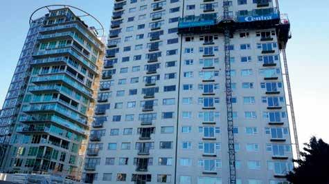
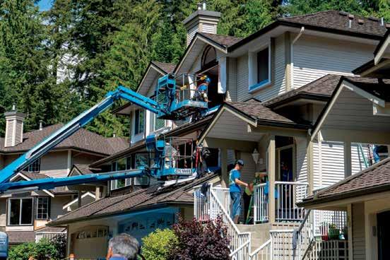
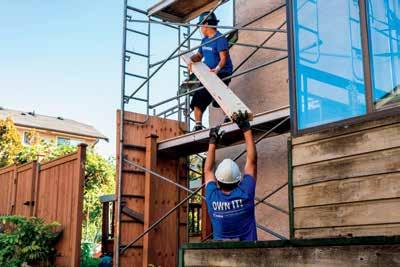
If you’re in need of exterior renovation work on condo and multifamily buildings, choose a company that can do it all. Centra has over 50 years in the industry, we handle windows, doors, and exteriors, and we’re the experts when it comes to code compliance and safety.

W i n d o w s & D o o r s
Costly aluminum products are no longer necessary! Save money without sacrificing quality with Centra’s vinyl windows and doors –whether the building is three floors or thirty. We manufacture our products to the highest standards and back them with a top warranty, giving you the peace of mind you deserve.

B u i l d i n g E n v e l o p e
We’re also building envelope specialists, and we’re equipped to deal with asbestos, mould, and rot. Reach out to our experts today and book a lunch and learn.

i n d o w s , D o o r s , & E x t e r i o r R e m e d i a t i o n
centra.ca 4705 102 Ave SE, Calgary, AB, T2C 2X7 info@centra.ca 403-279-2797

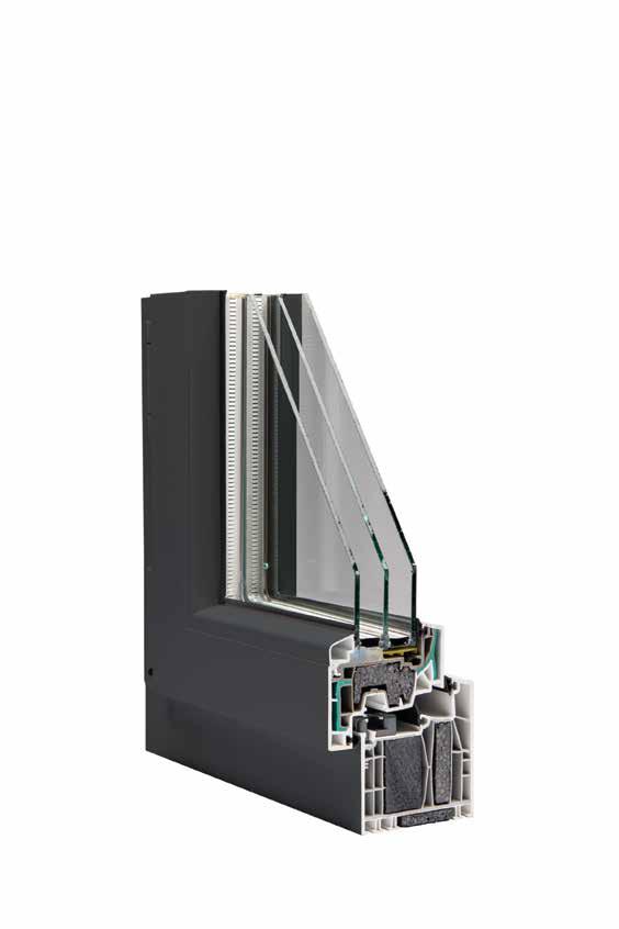
DUXTON Windows and Doors Edmonton, AB 780.435.0649 duxtonwindows.com The future is FIBERGLASS ü U-Values as low as 0.85 W/m2·K ü Tough frames with high wind-loading capacity ü Trusted by building envelope engineers across the prairies ü Find technical data at duxtonwindows.com/resources
RENU
WCPG
Fort St. John Passive House Low Hammond Rowe Architect
Engineering Inc.
Construction Ltd.
PRESIDENT / PUBLISHER
David Langstaff
MANAGING EDITOR
Kelsey James kelsey@delcommunications.com
SALES MANAGER

Dayna Oulion dayna@delcommunications.com
SALES REPRESENTATIVES
Brent Astrope | Colin James
Ross James | Mic Paterson
PRODUCTION SERVICES

S.G. Bennett Marketing Services
CREATIVE DIRECTOR / DESIGN
Kathleen Cable
COVER PHOTO COURTESY OF Casie Chou
PUBLICATION COMMITTEE
Bob Passmore | Ed Bushnell | Fred Edwards
Kevin McCunn | Jamie Murphy | Casie Chou
CONTRIBUTING WRITERS
Kieran Ager | Stephen Hunter
Jon Solland | Mark Hagel | Joseph Lstiburek
Ryan Cornforth | Suzanne Checkryn
© 2023 DEL Communications Inc. – All rights reserved. Contents may not be reproduced by any means, in whole or in part, without the prior written permission of the publisher. ABEC does not specifically endorse the editorial, products or services contained within this magazine. These products and services are presented here as an indication of the various possibilities in the Marketplace. ABEC wishes to advise the reader that sound Building Science Practices should be applied to any and all product or service selections. ABEC does not make or imply any warranties as to the suitability of any of these products or services for any specific situation. Furthermore, the opinions expressed in this magazine’s editorial content may not necessarily reflect the opinions of ABEC.”
While every effort has been made to ensure the accuracy of the information contained herein and the reliability of the source, the publisher in no way guarantees nor warrants the information and is not responsible for errors, omissions or statements made by advertisers. Opinions and recommendations made by contributors or advertisers are not necessarily those of the publisher, its directors, officers or employees.
Publications Mail Agreement #40934510
Return undeliverable Canadian addresses to: DEL Communications Inc.
Suite 300, 6 Roslyn Road, Winnipeg, Manitoba R3L 0G5
Email: david@delcommunications.com
PRINTED IN CANADA | 06/2023
08
11
12
4 AN ABECN/ABECS PUBLICATION
IN THIS ISSUE
Message from the ABEC North president
www.delcommunications.com 06
Message from the ABEC South president
North Board of Directors, South Board of Directors
10
Calendar of events
The Grenfell Tower fire incident: lessons for Canada (part one)
Case study: moisture accumulation and deterioration in exposed stucco-clad wood-framed walls
Moisture sensitive structures in Alberta
Meeting NECB 2017 with masonry veneers 45 Shakespeare does roofs 49 Spring has sprung... a leak? 50 The Revay Corner: so your project has sprung a leak... now what?
Industry expert Q&A: Jamie Murphy
Help send Eddie to camp and experience camp firsthand yourself
Index to advertisers
22
28
32
52
54
55


780.463.1886 estimating@moderncladding.ca 9552 26 Avenue NW, Edmonton, AB T6N 1H8 www.moderncladding.ca CENTRE 5010, RED DEER, AB ACM PANELS FABRICATED & SUPPLIED BY MODERN CLADDING FINISHES LTD.
Message from the ABEC North president
 Julien St-Pierre President, ABEC (North)
Spring! The time of change. I am excited to write this message as my first president's message in the shared Alberta Building Envelope Council North & South publication, Building Science Perspective
We have some new faces on the ABEC North's board of directors this year, and some who've been around since the re-inception of the council in 2019. Together, we are a dedicated group looking forward to advancing the building envelope industry in our region.
We are planning some exciting lunch presentations, continuing with our evening casual night connections and we have other events in the works. Our goal is to build upon the momentum that we've seen as pandemic restrictions have eased, and we're already seeing great turnout at our casual nights. There is great appetite for our industry to connect with one another, from envelope consultants, architects, contractors, glaziers, owners’ representatives, product suppliers, technical representatives and others: we want this council to offer great opportunities for our members to connect, learn and share experience from across our industry.
Stay tuned to ABEC North’s LinkedIn page and our new forthcoming website to stay up-to-date on our events, including our monthly luncheons, casual nights and a joint golf tournament with CSC Edmonton Chapter (June 15, 2023).
This magazine's theme, "spring has sprung a leak,” reflects on the challenging climactic conditions buildings experience in our region. Spring is when we transition from the frigid cold of our -40-degree winter lows to welcoming our (eventual) 30-degree warmth. Sudden and extreme temperature changes are taxing on our buildings and on the building envelope components. Building envelope components expand and contract at different rates to one another, resulting in challenges for the envelope to perform its core function: to keep the conditioned air in and the outside air out, and to keep the deluge of snow, ice melt and rain out of our buildings.
Happy reading!
Julien St-Pierre, P.Eng. President, ABEC North

6 AN ABECN/ABECS PUBLICATION

Message from the ABEC South president
Edward Bushnell President, ABEC (South)
Dear members and friends,
I am honoured and excited to lead our Council this year. I would like to take a moment to recognize the committed board members and volunteers that allow us to offer educational opportunities, host our networking events, produce this publication and much more. I also want to offer a special thank you to my predecessor, Fred Edwards, for his previous leadership and current mentorship. Our chapter continues to expand in exciting new directions and I greatly appreciate the opportunity to be a part of it.
I have built many valued relationships during my time in the industry, however, for those who don’t know me, let me briefly share my journey so far. I moved to Canada from the U.K. when I was 19. After working for a new home builder for eight years, in 2008 I started my own construction company, Fire Ant Contracting Ltd. Ten years ago, I had the opportunity to work on a building envelope restoration project and haven’t looked back since. After being a member for a few years, I had the opportunity to join the board of ABEC South in 2019 and have been proud to volunteer on this magazine’s committee since the first issue.

As our industry continues to expand and succeed, we also continue to hear that our industry is faced with various challenges including inflation and labour and material shortages. Despite these challenges, we are growing and evolving at a rapid pace. We are often seeing improvements in specialist building envelope products and newer, better technology. The foundations of construction have not changed significantly, but the details have become more complex. With these complexities, the technological advancements in our industry have also provided us with more resources than ever. Taking advantage of these resources to educate ourselves, our peers and our clients will result in our ability to balance these advancements with a higher level of efficiency and understanding. So long as our industry can keep up with the latest products, techniques and technology to ensure we advance forward, our industry will remain in good standing.
Alberta Building Envelope Council is a non-profit society dedicated to the promotion and education of building envelopes and warmly welcomes individuals with similar interests. We continuously network with industry leaders, share innovation and technology and discuss new concepts and ideas. Our primary focus is education, and we are working with other organizations and education institutes to bring new learning opportunities to various areas of our industry. In this spring edition, you will discover our upcoming events and some well-written articles we hope you enjoy reading.
Looking forward to another great year.
Edward Bushnell President, ABEC South
8 AN ABECN/ABECS PUBLICATION
DESIGNING NET-ZERO WALL ASSEMBLIES? ENERGY STAR WINDOW PRODUCTS?
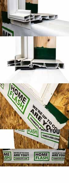
MAXIMIZE BOTH ELEMENTS WITH HOMEFLASH SYSTEMS


HomeFlash ® is a revolutionary sill pan flashing system, engineered to solve the damaging e ects of water infiltration into a wall assembly. With changing National and Provincial Building Codes, HomeFlash ® o ers state-of-the-art sill pan systems that are engineered and tested to help eliminate moisture failures and exceed the performance of self-adhering membranes or molded PVC products.
ALL-IN-ONE PRODUCT
DESIGN
One-Piece membrane creates an impermeable seal to prevent moisture infiltration
½ inch positive slope design to create and maintain ideal drainage away from the structure
Eliminates the need for multi-product designs
COMPLIANCE
Exceeds National Energy E ciency standards
Fully compliant and tested to ATSM Standards
Fully compliant with National Building Code
Testing pedigrees exceed industry requirements
ENGINEERING
Closed cell foam pan insulates and reduces through-wall air flow
Rugged design allows for installation in extreme temperatures (-20 C to 30 C)
Self-adhering PVC shimming system
COST SAVINGS
Installs in seconds
Reduces labour costs
Eliminates sill pan insulation costs
Everything is included; no need to purchase any additional materials
SAVE TIME AND MONEY WITH OUR ONE-PIECE SILL PAN SOLUTION FIND OUT MORE |
HOMEFLASH.CA 403.938.6100 INFO@HOMEFLASH.COM HOMEFLASH.COM
North Board of Directors
JULIEN ST-PIERRE – PRESIDENT
RYAN ASSELSTINE – TREASURER
CHUCK BARNICOTT – MEMBERSHIP
NICOLE MALIK – SECRETARY
MARLA SNODDON – PROGRAMMING
JAMIE MURPHY – PUBLICATION
KEVIN MCCUNN – TECHNICAL REVIEWER
CHRISTA VAN DYK – DIRECTOR
JOE MIS – DIRECTOR
South Board of Directors
ED BUSHNELL – PRESIDENT
FRED EDWARDS – PAST PRESIDENT
KRIS WALL – DIRECTOR
ANTON VLOOSWYK – TREASURER
STEPHEN HUNTER – EDUCATION COMMITTEE
MAIREAD WALSH – MEMBERSHIP
GREG MARTINEAU – PROGRAMMING
MIKE DIETRICH – SECRETARY
RANDY KIEZ – DIRECTOR
MARTY DEEMTER – EDUCATION COMMITTEE
JON SOLLAND – EDUCATION COMMITTEE
10 AN ABECN/ABECS PUBLICATION
www.aegiswest.ca • Assessment • Leak Investigation • Studies • Cladding Systems • Glazing Systems • Roofing Assessment and Design • Reserve Fund Studies • Parkade Restoration and Waterproofing COMMERCIAL CONDOMINIUM INSTITUTIONAL AEGIS WEST ENGINEERING INC. Joel Smith, P.Eng. joel@aegiswest.ca 780.340.3681 Garett Cochrane, P.Eng. garett@aegiswest.ca 780.238.3418 EXPERIENCE | PRACTICALITY | SERVICE
CALENDAR OF EVENTS
2023 Joint Golf Tournament with CSC Edmonton – June 15, 2023
Annual General Meeting – September 27, 2023


October Luncheon – October 25, 2023
November Luncheon – November 29, 2023
Casual Nights
Second Tuesday of the Month – Location TBD

ALBERTA BUILDING ENVELOPE COUNCIL / NORTH & SOUTH CHAPTERS 11
Construction Lawyers. HMC Lawyers LLP #1000 903 8th Ave SW Calgary, AB T2P 0P7 (403) 269-7220 www.hmclawyers.com
THE GRENFELL TOWER FIRE INCIDENT: LESSONS FOR CANADA (PART ONE)
By Kieran Ager, MSc, P.Eng, CP, CEng, PMSFPE,
CFPS, LMDG, Calgary, Canada, Email:
Kager@lmdg.com
Author bio: Kieran Ager is an internationally trained and experienced fire engineer and code consultant with 15-plus years within the fire industry and leads the Calgary office of LMDG. He has led the development of numerous iconic and notable projects in Canada, United Kingdom, Myanmar, United Arab Emirates and the United States. Kieran specializes in developing solutions for emerging challenges within the built environment, such as high-rise construction and integration, the promotion and use of sustainable materials (mass timber) and embracing and advancing emerging technologies that influence industry and society.

On June 14, 2017, a fire incident occurred in London, England that has had the single most impact on fire safety regulation in recent memory. Although ongoing, the ramifications of the incident extend to the competence of designers (including fire engineers and architects), the cladding and insulation manufacturing sector, regulators, firefighters and the fabric of fire safety principles. This is summarised in the remarks of Richard Millett KC, who stated the following in his closing statement from the second phase of the investigation: “From all of the evidence that you have heard in phase two, you are able to distill a single overall conclusion: that there was nothing unknown or not reasonably knowable, which caused or contributed to the fire and its consequences. On the contrary, each and every one of the risks which eventuated at Grenfell Tower, on that night, were well known by many and ought to have been known by all who had any part to play. As a result, you will be able to conclude with confidence that each and every one of the deaths that occurred in Grenfell Tower on 14 June 2017 was avoidable.” [1]
This article is first of a two-part review of the Grenfell fire incident. This article presents an overview of the building design, fire strategy and fire incident with the second article focusing on the investigation, lessons learnt, tolerable risk as a measure of fire safety and a comparison of testing regimes.
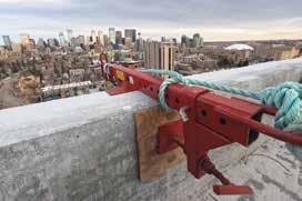
The building
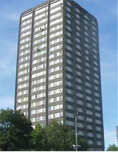
The Grenfell tower was not unique in height, occupancy or design. The tower is in fact typical of the late '60s design era being a social housing, non-sprinklered, 24-storey building of concrete frame with concrete spandrels and columns [Figure 1] [2].
12 AN ABECN/ABECS PUBLICATION
Figure 1 Grenfell tower.
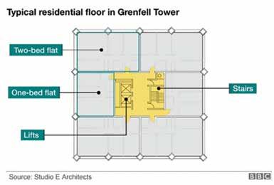
Figure 2 Typical residential floor.
Services to meet your needs:
• Our goal is to provide the most up-to-date equipment that meets or exceeds all standards.
• We provide professional rigging upon request at any location.
• We promise to provide the safest solution every time!
Rental fleet:
• We have an extensive stock of rental equipment to customize set-ups for every unique project that comes about.
Training:
• We offer an 8-hour Swingstage Operator & Safety Training Certificate program.
Sales & Service:
• Because of our extensive stock of rental equipment we are able to sell all components or can obtain any and all equipment you may be looking for.
We manufacture, supply, install and service a variety of fall protection equipment.


• Anchors
• Ladders
• Horizontal Lifelines
• Guardrails
• Self-Retracting Lanyards
• Davit systems
• CWB certified 47.1 & 47.2Aluminum and Steel Welding and Fabrication
We also provide inspections, testing and certification. Contact us for all your fall protection needs.

Alberta Specialty Services Ltd. #4 2705 5th Avenue NE, Calgary T: 403-225-2759 TF: 1-877-347-5588 E: info@albertaspecialtyservices.com www.albertaspecialtyservices.com
Turn-Key Fall Protection Inc. #4 2705 5th Avenue NE, Calgary T: 403-253-2777 TF: 1-877-711-2777 F: 403-253-4560 E: info@turn-keyfallprotection.com www.turn-keyfallprotection.com
The internal layout of the building was also not unique with one to two bed apartments centred around a central core containing lifts, refuse chute and a single stair configuration [Figure 2] [3].
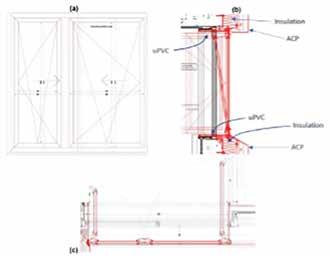
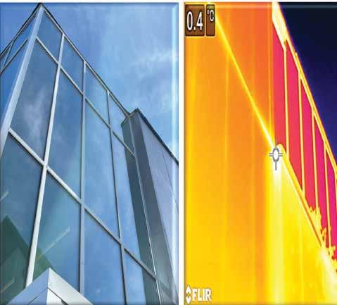
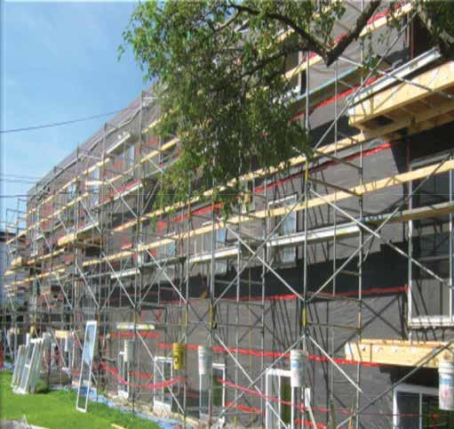
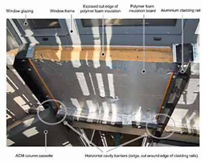
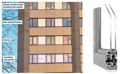
The tower was originally built with a non-combustible exterior with insulation located inboard of the concrete. The building was, however, renovated during 2014-2016 with an aspiration to improve the building energy performance. ACM (aluminium composite material) panels were installed outboard of the existing concrete structure in conjunction with new glazing. The location of the glazing is a critical factor for the subsequent fire development and spread up the
façade as it is believed that the glazing units were installed on the plane of the new insulation (polyethylene core) which is outboard of the thermal barrier provided by the existing concrete structure. Further, there was no evidence of fire blocking (cavity barriers as referred to within the UK Building Regulation) with a 50 mm cavity behind the metal cladding. Figure 3, Figure 4 and Figure 5 below illustrate the details and location of the window systems within the façade [4] [5]
Post-incident analysis has indicated that no less than 268 buildings with ACM cladding are located in London, 72 in Manchester, with 141 in the rest of
England. [6] To summarise, the Grenfell tower building, design and cladding are indicative of a ‘typical’ social housing block of flats in the U.K.
Fire strategy
Grenfell tower operated a ‘stay put’ evacuation policy that is a recognised compliant means to support building occupants. Building Regulations document – Approved Document B states the following: [7]
Separate guidance applies to means of escape within the flat and within the common parts of the building that lead to a place of safety. Flats at ground level are treated similarly to dwelling houses. With increasing height, more complex provisions are needed.
The provisions in this section make the following assumptions:
a) Any fire is likely to be in a flat,
b) There is no reliance on external rescue,
c) Simultaneous evacuation of all flats is unlikely to be necessary due to compartmentation,
d) Fires in common parts of the building should not spread beyond the fabric in the immediate vicinity. In some cases, however, communal facilities exist that require additional measures to be taken.
14 AN ABECN/ABECS PUBLICATION
Figure 3 Façade and glazing indicative illustration.
Figure 4 Details of the window system used in the refurbishment.
Figure 5 Typical locations of cut cavity barriers and vertical cladding rails outside Flat 13 on the fourth floor.
Provisions are recommended to support a stay put evacuation strategy for blocks of flats. It is based on the principle that a fire is contained in the flat of origin and common escape routes are maintained relatively free from smoke and heat. It allows occupants, some of whom may require assistance to escape in the event of a fire, in other flats that are not affected to remain. Sufficient protection to common means of escape is necessary to allow occupants to escape should they choose to do so or are instructed/aided to by the fire service. A higher standard of protection is therefore needed to ensure common escape routes remain available for a longer period than is provided in other buildings.
To summarise the strategy, the building does not contain a central fire alarm system. Rather, a combination of local point detection and alarm within each residence is provided to alert the flat occupants only of a fire condition. The flat is enclosed within fire resisting construction (one hour fire resistance rating) that should inhibit fire spread beyond the flat of origin with the occupants of the affected flat responsible for contacting the fire and rescue service. Neighbouring flats are expected to stay put during a fire emergency and only evacuate should smoke or contaminants ingress into their location.

The single escape stair and common escape route(s) is subject to enhanced protection in an effort to maintain tenable conditions should a limited number of occupants choose to escape. There are multiple means to satisfy the smoke control of common escape routes criteria, but the basic premise relies upon a means to vent smoke from the common corridor in conjunction with an inlet vent located on the top storey of the stair. The activation of the vents occurs upon receipt of a smoke detector located in the common area of each floor area. Activation of this alarm does not facilitate building wide alert or initiate evacuation.
The incident
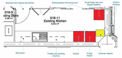
At 00:54:29 a.m. on June 14, 2007, Mr. Behailu Kebede made the initial emergency 999 call to the London Fire brigade (LFB) after being woken by a smoke alarm sounding. Upon investigation he discovered smoke in his fourth-floor kitchen in the vicinity of
the fridge/window area. He successfully relayed this information to the LFB dispatcher including his address of flat 16. It is widely understood that the origin of the fire was the Hotpoint fridge freezer located adjacent to the east façade within the kitchen [5].
ALBERTA BUILDING ENVELOPE COUNCIL / NORTH & SOUTH CHAPTERS 15
The first of the four fire crews dispatched to this incident arrived on scene at 00:59 with the initial crew traversing the stairs and entering flat 16 at approximately 01:07. After initially searching the bedrooms, the firefighters entered the kitchen and noted an “isolated curtain of flame from about 2 - 3 feet in the air to the ceiling.” [8] Whilst the firefighters were actively suppressing the fire, Mr. Kebede noted from outside an orange glow of flames around the kitchen window that evolved to visually more intense burning.
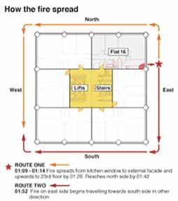
As the fire crews were leaving the building after having successfully extinguished the kitchen fire, firefighters also spotted external flaming that spread up the exterior of the building at a ‘significant’ rate. Evidence showed that in less than 30 minutes after the arrival of firefighting crews, the fire had spread to the top floor of the east side of the tower. By 01:42, the fire had spread to the north side of the tower [9] [Figure 7] [8]
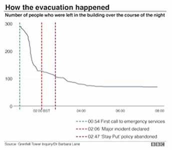
The next significant event of the incident was the declaration of the fire as a ‘major incident.’ The reality being that 40 fire engines were either enroute or at the Grenfell tower incident. With no central fire alarm to alert building occupants, evacuation was manifested by occupants alerting their neighbours or firefighting efforts. Fortuitously due
to Ramadan, many observing Muslim residents were awake for the pre-dawn meal of suhur which allowed them to notify other building occupants. With the fire rapidly spreading up the external of the building, the fire was able to re-enter on multiple simultaneous floors creating many seats of fire that ultimately overwhelmed the single stair means of escape. Communication from the emergency services was such that building occupants were instructed to remain in their flats in accordance with the stay put policy. This strategy was formally abandoned by the fire service at 02:47 when the Incident Commander gave the order to “advise people to
make efforts to leave the building.” 144 people evacuated the tower before 01:38 but only 36 after the stay put guidance was abandoned [Figure 8] [8]. The post incident investigation stated that the stay put policy had ‘substantially failed’ by 01:26. [9]
By 04:30, the whole building was engulfed with 100 flats on fire. Firefighting crews reported thick smoke and zero visibility within the tower with riot police deployed to protect firefighter with riot shields external to the building. In total, 250 firefighters from 70 fire engines attended the scene in efforts to extinguish the fire. It was noted the over 100 firefighters were inside the tower
16 AN ABECN/ABECS PUBLICATION
Above: Figure 6 Kitchen layout (indicative). Right: Figure 7 Fire spread.
Figure 8 Evacuation.


ALBERTA BUILDING ENVELOPE COUNCIL / NORTH & SOUTH CHAPTERS 17
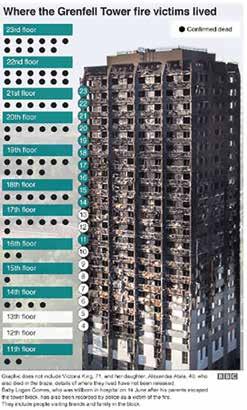
Figure 9 Locations of the deceased. at any given time. The fire ultimately self-extinguished by 01:14 more than 24 hours after the initial fire started. Of the near 300 occupants within the tower at the time of the fire incident, 72 people ultimately perished. Figure 9 illustrates the location of the deceased. Of note is that multiple residents attempted escape and, due to unknown reasons, ultimately sought refuge on upper floor levels with friends and neighbours. The death toll is inclusive of those that perished during the fire incident and those that died later as a consequence of the events of that night.
Summary
The Grenfell tower fire incident is a catastrophic event and, to paraphrase the words of Richard Millett KC, the deaths were avoidable. Part 2 of this series will explore the subsequent investigations, lessons learnt, tolerable
BUILDING REVITALIZATION
risk as a measure of fire safety and a comparison of testing regimes against the Canadian regulatory framework.
References
[1] P. Apps, “Grenfell Inquiry 'able to conlcude every death was avoidable' as its lawyer slams ongoing 'merry-go-round' of buck passing,” Inside Housing, 10 11 2022.
[2] Wikipedia, “Wikipedia,” Wikipedia Foundation Inc, 13 April 2023. [Online]. Available: https://en.wikipedia.org/ wiki/Grenfell_Tower. [Accessed 16 April 2023].
[3] J. B. Morley, “An Architect's Guide to the Grenfell Tower Disaster,” [Online]. Available: https://architizer.com/blog/ inspiration/stories/the-architects-guide-tothe-grenfell-tower-disaster/. [Accessed 16 April 2023].
[4] M. Koohkan, V. Drean, B. Girardin, E. Guillaume, T. Fateh and X. Duponchel, “Reconstruction of the Grenfell Tower Fire - Thermomechanical Analysis of Window Failure During the Grenfell Tower Disaster,” Fire Technology, vol. 57, pp. 69-100, 2021.
[5] L. Bisby, “Grenfell Tower Inquiry: Luke Bisby - Phase 1 - Final Expert Report,” The University of Edinburgh, Edinburgh, 2018.
[6] S. Corker, “Dozens of blocks still have Grenfell-type cladding,” BBC, 20 January 2022. [Online]. Available: https://www. bbc.com/news/business-60069433. [Accessed 16 April 2023].
[7] HM Government, The Building Regulations 2010 - Fire Safety Approved Document B Volume 1: Dwellings2019 edition incorporating 2020 and 2022 amendments - for use in England, London: HM Government, 2019.
For
please email Jamie Fleese at JPFleese@pcl.com
[8] BBC, “Grenfell Tower: What Happened,” 29 October 2019. [Online]. Available: https://www.bbc.com/news/ uk-40301289. [Accessed 16 April 2023].
[9] B. Lane, “Grenfell Tower - Fire Safety Investigation,” 22 October 2020. [Online]. Available: https://www.grenfelltowerinquiry. org.uk/evidence/dr-barbara-lane. [Accessed 16 April 2023]. n
18 AN ABECN/ABECS PUBLICATION
MAXIMIZING POTENTIAL AND CAPITALIZING ON EXISTING STRUCTURES RENEWAL VS REBUILD 40% SCHEDULE SAVINGS 25–35% BUDGET SAVINGS
PCL.COM SOLUTIONS • Building Envelope Upgrades • Mechanical (HVAC) Upgrades • Electrical Upgrades • Technology Enhancements • Amenity Retrofits
more information,


ALBERTA BUILDING ENVELOPE COUNCIL / NORTH & SOUTH CHAPTERS 19 With vinyl-backed Tufdek, you avoid contaminated welds and lower weld integrity found with fabric-backed products. Our non-wicking internal weft reinforcement gives you up to 14 times higher tear resistance than our competitors. Installed exclusively by Authorized Dealers, Tufdek offers the complete waterproofing solution for your next project. Specify the beSt, Specify tufdek! www.tufdek.com | 877-860-9333 waterproof deck solutions First at Making Buildings Last To learn more about us, please visit wadeconsulting.ca Billy Huet, P.ENG Principal, Building Envelope Consultant 780 977 5437 | bhuet@wadeconsulting.ca Julien St-Pierre, P.ENG Principal, Building Envelope Consultant 780 239 8459 | jsp@wadeconsulting.ca Making Tomorrow Better Than Today. We bring a unique, purposeful approach to design thinking through thoughtful placemaking that inspires human connection, community, and social wellbeing. People are at the heart of everything we do. www.metafor.studio
North
in
Ask us about the Defender 88PH+ XI : the first Passive House Institute (PHI) cold climate certified window system manufactured in
America! Available
Spring 2023.
Windows + Door for Passive House Projects
Innotech Windows + Doors is a Canadian manufacturer of Passive House Institute certified windows and doors. With over twenty years of dedicated experience, Innotech delivers the manufacturing expertise and product performance required for Passive House and other highly sustainable projects.
The Defender 88PH+ System is a natural evolution in a proven history of manufacturing excellence. High-quality components, expertise in manufacturing, and robust testing and quality assurance programs result in highly durable windows and doors with superior thermal performance, air and water resistance, and dimensional stability.
View our portfolio of Passive House certified multi-family projects: innotech-windows.com/passive-house
Architec tural Rendering by Cornerstone Architec ture
THE PEAK IN VANCOUVER, BC Passive House Multi-Family Project by Cornerstone Architecture and BOLD Construction.
innotech-windows.com
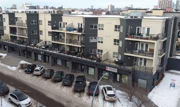
CASE STUDY: MOISTURE ACCUMULATION AND DETERIORATION IN EXPOSED STUCCOCLAD WOOD-FRAMED WALLS
By Stephen Hunter, P.Tech.(Eng.) Senior Project Manager, Sense Engineering
Author bio: Stephen is a building envelope specialist at Sense Engineering in Calgary. He provides building envelope engineering services for new and existing buildings.

Introduction
This case study is about a failure involving moisture accumulation and deterioration in stucco-clad wood-framed exterior walls at a residence located in Calgary, Alt. (Photographs 1 – 2).
It includes a summary of the investigation methodology and observations. There is also a discussion on why the failure occurred and what could have been done to prevent it.
Methodology
This investigation began after the homeowner noticed a mouldy smell, and later identified moisture and deterioration within the northwest-facing exterior wall assemblies of their residence.
We discussed the issues with the homeowner. We also reviewed the drawings and discussed the construction of the residence with the builder.
This was followed by a visit to the residence. Prior to our visit, the builder had removed all the stucco from the northwest-facing exterior wall assemblies. They left most of the stucco accessories, building paper and metal flashings in-place.
We started by reviewing the areas where deterioration was evident. We then proceeded to review the remainder of the building enclosure to gain a better understanding of the completed condition.
We also returned on a regular basis to measure the moisture content of the exterior sheathing in several locations in the other exterior wall assemblies. We recorded the moisture content in the field of the wall and around interface details (e.g. around windows, deck-to-wall interfaces, etc.). Moisture content measurements were taken following prolonged periods of rainy weather.
Observations
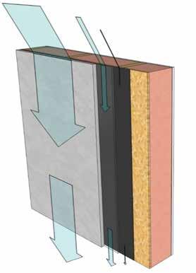
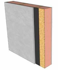
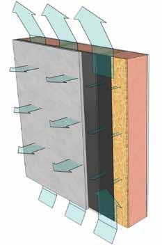
The wall assembly was constructed as follows (from exterior to interior) (Figure 1):
• Acrylic finish coat
• 20mm reinforced cement stucco cladding
• two layers asphalt saturated kraft building paper
• one 10mm oriented strand board (OSB) sheathing
• 2 x 6 wood stud wall with infill batt insulation
• 6 mil polyethylene sheet layer
• 13mm gypsum board, painted
This is a commonly utilized wall assembly in the Canadian prairies, which receives less rainfall than regions to the east and west.
22 AN ABECN/ABECS PUBLICATION
Figure 1: Existing stucco-clad wood-framed wall.
The residence is two storeys tall and has pitched roofs with ~400mm overhangs. It is located at the edge of the city, with a large open tract of land to the northwest.
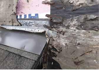
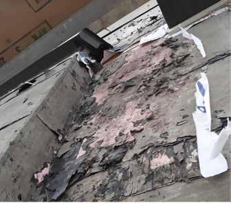
The building paper and OSB sheathing were deteriorated in many locations on the northwest-facing wall assemblies. The deterioration was concentrated below the edges of two small roofs located at the second floor line, and at a horizontal expansion joint located at the bottom of the roof trusses (Photographs 1 – 2). The amount of deterioration varied along the length of the expansion joint. No deterioration was observed around a first-floor window.
The metal apron flashings at the two roofs were properly lapped into the building paper to shed water. However, they did not have end dams (Photograph 3). The “W” style metal expansion joint was installed over continuous building paper (Photograph 4).
The building paper was installed in two continuous layers
Table 1:
Moisture Content and Risk of Fungal Growth Moisture Content
(%) Description Risk
19% or lower Safe moisture content (i.e. will not support rot)
Between 19% & 28% May support fungal growth (i.e. support rot once initiated)
28% or higher May initiate fungal growth (i.e. initiate onset of rot)
Low
Medium
High
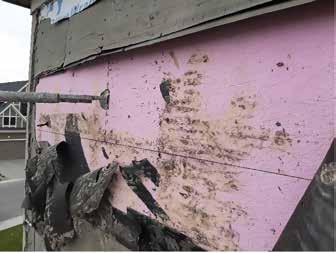
and was lapped properly to shed water. The outer layer of building paper was faded, likely from being left exposed during construction. The inner layer was in good condition.
When measurements were taken on the remaining walls, the moisture content of the sheathing was consistently below 15 per cent, which is low enough to prevent deterioration.
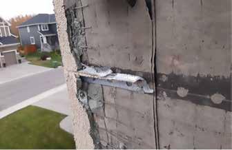
Table 1 provides information on moisture content and the associated risk of fungal growth in wood materials.
ALBERTA BUILDING ENVELOPE COUNCIL / NORTH & SOUTH CHAPTERS 23
Photograph 1: Typical condition below a roof.
Photograph 2: Typical condition below an expansion joint.
Photograph 3: Apron flashing without end dams.
Photograph 4: Typical horizontal expansion joint. The building paper was in good condition in this location but deteriorated further to the west.
Discussion:
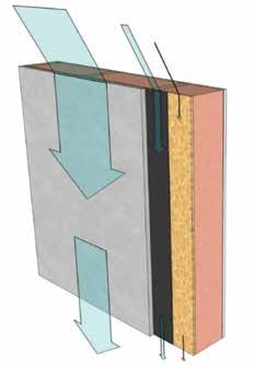
‘Drained-screened’ exterior wall assemblies like this stucco clad wall rely on a series of imperfect layers or ‘screens’ to drain rainwater. At each layer some water is drained, while the rest is either transmitted to the next layer or stored (Figure 2).
Successively smaller amounts of water are transmitted to deeper layers. In this assembly it is important that little to no rainwater reaches the OSB sheathing and framing, which are sensitive to moisture-induced deterioration.
Unless appropriately detailed, much more water will be transmitted through the stucco cladding layer at joints and other interfaces than in the field of the wall, especially where concentrated runoff occurs (e.g. edges of roofs, balconies, etc.). Appropriate sealant and flashing details are required at these interfaces to minimize the amount of water that is transmitted past the outermost surfaces.
Water that is not immediately drained out of the assembly at any given layer must be removed by other drying processes (e.g. diffusion, capillary flow and air flow that transports water out of the assembly) at a rate sufficient to prevent moisture from accumulating to levels that will cause development of mould, dry rot fungi, and associated deterioration (Figure 3). Due to the impermeable polyethylene sheet layer on the interior side of the assembly, drying must occur to the outside.
Modern day polymer modified cement stucco systems with acrylic coatings and OSB sheathing have relatively low permeance, which limits outward drying from within the assembly. Negligible convective drying occurs in this type of assembly, as there is minimal air movement through and between the layers.
Consequently, when stucco cladding is combined with a moisture sensitive wood framed wall in the configuration constructed at this residence, the result is an assembly that can only accommodate a small amount of water transmission past the stucco layer before there is a risk of moisture accumulation and deterioration.
Location, terrain, height, orientation and building form all influence the amount of rainwater falling on a wall assembly, and the wind force driving it.
At this residence, the northwest-facing wall assemblies are exposed to open terrain, and Calgary is known for its winddriven rain from this direction. There are roof overhangs, but much of the exterior walls are not well sheltered during winddriven rain events due to the height of the building and strong winds.
Due to these factors, the northwest-facing wall assemblies at this residence have a higher rain load. The other walls are also exposed to wind-driven rain, though less often.
North-facing walls also dry slower owing to less solar heating than the other walls. This also increases the risk of moistureinduced deterioration.
On the northwest-facing wall assemblies of this residence, water was transmitted past the cladding plane at the ends of the apron flashings and expansion joint. The apron flashings did not have end dams to prevent lateral flow of water
24 AN ABECN/ABECS PUBLICATION
Figure 3: Drying in the existing stucco-clad woodframed wall.
Figure 2: Rainwater transmission in the existing stucco-clad wood-framed wall.
from the flashing to behind the stucco. The “W” style metal expansion joint permits water to bypass the cladding at the interfaces between the stucco and metal profile.

The variable pattern of deterioration below the expansion joint was likely due to the varying quality of the seal between the stucco and “W” style expansion joint, resulting in more water bypassing the stucco in some locations than others.
Drainage in this assembly is limited between the stucco and building paper. Due to this, water would be retained in this space and transmitted through the building paper.
Liquid water transmission through the building paper can occur at fasteners and laps. As the paper itself has a limited capacity to resist moisture migration, water can also be transmitted through it in liquid and vapour states if sufficient water is retained within the assembly for long periods of time. Consequently, water would reach the moisture sensitive OSB sheathing and framing.
The ability of the building paper to resist moisture migration is also reduced when it is deteriorated. Deterioration occurs when it is left exposed to the sun and/or when it is saturated with water for long periods of time.
Due to the excess water transmission into deeper layers, and the

limited drying capacity of the assembly, it’s expected that the wetting rate was higher than the drying rate for the spring and summer months, when Calgary receives most of its precipitation. This resulted in moisture accumulation and deterioration.
Prevention
Even in the relatively dry climate of the Canadian prairies, we must be cautious when using the type of assembly featured in this case study. The drying capacity of the assembly is low, and moisture accumulation can occur due to relatively minor defects.
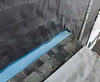
The first step in preventing this type of failure is to ensure all horizontal interfaces have flashings with end dams (Photograph 5). Flashings can also be used in place of horizontal “W” style metal expansion joints.
Installation of sealant at appropriate interfaces is also important. Combined, these measures will reduce water transmission past the outermost surfaces of the wall assemblies.
It is also important to ensure the building paper is not left exposed for a long duration before the stucco is installed to ensure it is in good condition and will perform as intended.
In lower-exposure situations in this relatively dry climate, these measures are normally sufficient. Implementing these measures
ALBERTA BUILDING ENVELOPE COUNCIL / NORTH & SOUTH CHAPTERS 25 DELIVERING CREATIVE, VALUE-SOLUTIONS IN A CHALLENGING WORLD IS WHAT GETS US UP EVERY MORNING. Sense Engineering provides client-centric building engineering and consulting services for new and existing buildings of all types. We provide restoration, structural, building enclosure, capital planning and energy/sustainability services. We are a collective of highly experienced engineers and technicians with offices across Canada, united by our commitment to understanding – and caring about– our clients’ needs. Vancouver | Okanagan | Calgary | Hamilton | Toronto | Niagara | Ottawa www.senseengineering.com | makessense@senseengineering.com | 403-543-2258
would have reduced the risk of a failure at this residence, and may have prevented it.
It is noteworthy that no damage was observed around the window on the northwest-facing elevation. The flashings were properly lapped into the building paper. They also had adequate slope and end dams. Sealant was also present between the windows and adjacent materials to minimize rainwater transmission.
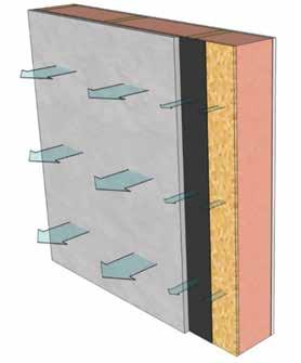
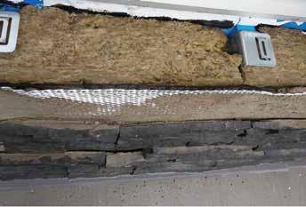
The drainage and drying capacity of the assembly can also be improved significantly by incorporating a drained and vented airspace inboard of the stucco. Entangled net drainage mat with a filter fabric facing works well (Figure 4).
Due to the airspace, drainage between the stucco and building paper is significantly improved. More water drains at the backside of the stucco layer, meaning less water is transmitted to deeper layers (Figure 5). The airspace also acts as a capillary break, preventing capillary transport of water directly between the stucco and underlying materials.
If the airspace is connected to the exterior at its top and bottom, convection through the airspace also removes water from it and the adjacent materials, significantly improving drying capacity (Figure 6).
Due to the combination of lower rainwater transmission and better drying capacity, this assembly can satisfactorily manage higher rain load conditions. This type of assembly is employed in wetter regions, like the west coast, where they learned a while ago that nothing less is satisfactory.
In our prairie climate, this drained and vented airspace is often required in higher exposure situations like the northwest-facing walls at this residence and anything higher than low-rise residences. It also provides rainwater control redundancy for lower rain load conditions.
To illustrate the difference in moisture control in these two types
26 AN ABECN/ABECS PUBLICATION
Photograph 5: Roof apron flashing with end dams.
Figure 4: Stucco-clad wood-framed wall with a drained and vented airspace inboard of the stucco.
Figure 5: Reduced water transmission after incorporating a drained and vented airspace.
Figure 6: Improved drying capacity in an assembly with a drained and vented airspace, due mainly to convective drying.
of assemblies, hygrothermal simulations were created for this residence (Figures 8 and 9). The conditions simulated were a north-facing wall of < 10 meter height with limited overhangs in open terrain. The simulations were created using the WUFI software package in accordance with ASHRAE Standard 160 - Criteria for Moisture-Control Design Analysis in Buildings. In both plots, the green line indicates relative humidity at the outside face of the sheathing. The red line indicates the temperature at the same location.
Relative humidity was used, as it’s a good indicator of the threshold for mould development, and the lower limit of when deterioration can occur. Figure 7 below provides the critical relative humidity as a function of temperature for moisture sensitive materials like OSB and untreated wood framing. It is based on the function for critical relative humidity for sensitive materials in ASHRAE Standard 160.
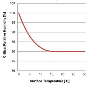
We can see in Figure 7 that for moisture-sensitive materials, extended periods of high relative humidity (> 85 per cent) concurrent with warm temperatures (> 15OC) results in a risk of mould development.
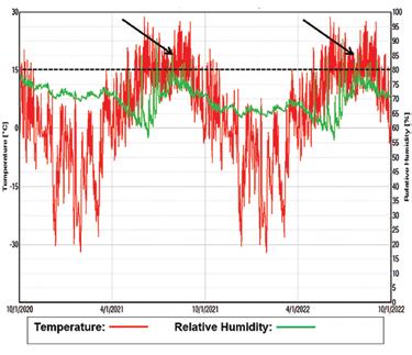
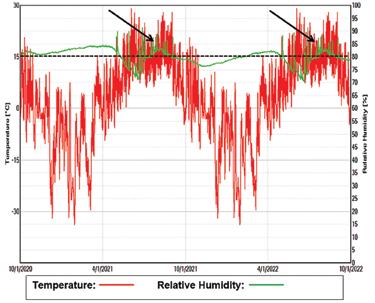
In Figures 8 and 9 below, these periods of higher risk are indicated by arrows. These periods of higher risk occur far less frequently and for shorter durations in the assembly with a drained a vented airspace than the assembly without one. Consequently, the risk of moisture accumulation and deterioration is substantially reduced by the addition of a drained and vented airspace. This is supported by observations in the field.
As noted, incorporating a drained and vented airspace inboard of the cladding plane is commonplace in areas with higher rain load conditions, like the west coast. Here on the prairies, a drained and vented airspace should be provided in higher exposure situations that result in higher rain loading. For lower exposure situations, the risk of moisture accumulation and deterioration is relatively low if appropriate interface details are implemented, and the stucco is sufficiently thick.
However, adding a drained and vented airspace provides improved performance and redundancy in all situations. An assembly with this airspace is more likely to perform well, even if there are deficiencies like those observed at this residence. It will also perform better over time as sealant materials degrade. For the minor additional cost and substantially improved performance, this is a design element that should be considered in all situations. When in doubt, include the airspace – you may save yourself and others a painful lesson. n
Figure 9: Temperature and humidity at outside face of sheathing in a wall with a drained and vented airspace.
Figure 7: Critical surface relative humidity for sensitive materials as a function of temperature.
Figure 8: Temperature and humidity at outside face of sheathing in a wall without a drained and vented airspace.
MOISTURE SENSITIVE STRUCTURES IN ALBERTA
By Jon Solland, P.Eng., RRC, RRO

Author bio: Years of specialized building envelope project work have provided Jon with a strong understanding of what buildings in Calgary need to withstand local environmental factors. He focuses on supporting large clients with effective envelope designs, asset management tools and condition reports, as well as skills in project management, contract administration and construction review that will lead their projects to success. Jon’s priority is solving client’s problems through creative solutions that will meet both their needs and constraints.Jon is a unique consultant in Alberta, professionally designated as both a Registered Roof Consultant (RRC) and a Professional Engineer. An active leader in the industry, Jon serves as a Director on the International Institute of Building Enclosure Consultants (IIBEC) Canadian Prairies Chapter, and as a Director on the Alberta Building Envelope Council South (ABEC).
Introduction:
Moisture penetration from building envelope and roofing leaks can cause significant damage to a structure. Moisture facilitates galvanic corrosion and provides conditions for organic growth. Identifying catalysts that accelerate failure is crucial to understanding and mitigating the risk of such failure.
In this article, we will explore three examples of how moisture deterioration can be exacerbated by latent building conditions.
Moisture as a Transport Mechanism for Phenolic Insulation to Corrode Steel Components:
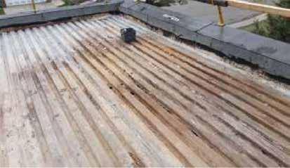
Phenolic foam insulation was commonly used in North American roofing between 1980 and 1992 (up to 1995 in other areas of Canada) as a new and improved alternative to fiberboard and fiberglass insulations. Roof insulation had been gradually moving from wood fiberboard to higher R-value foamed plastics and fiberglass. The first generation of phenolic had an advertised nominal R-10 per inch (RSI-1.8 per 25mm).
By the early 1990s, building owners and industry professionals began noticing corrosion problems over steel decks. Moisture allows the acid contained within phenolic to migrate and act as a catalyst for corrosion of steel components. This can result in significant structural damage and compromise the safety of the building. Corrosion can occur when the insulation is installed in direct contact with metal components, such as steel deck panels or fasteners. However, corrosion is not limited to directly adjacent elements. Acid-laden moisture can travel to wall
28 AN ABECN/ABECS PUBLICATION
Significant corrosion of the metal deck during roof removal. No roof leaks were reported in the location prior to removal (Courtesy of Petra Contract Services Ltd.)
Corrosion caused loss of structural integrity of the metal roof deck in this Calgary school (Courtesy of Petra Contract Services Ltd.)
QUALITY CONSTRUCTION DEDICATED MANAGEMENT FULLY QUALIFIED AND TRAINED IN HOUSE CREWS FOR: Demolitions Window and Door Replacements Structural Repairs and Re-Builds Building Envelope Waterproofing and Detailing
Cladding Installations Soffit and Fascia BEFORE AFTER 15835 112 Ave NW Edmonton, AB T5M 2V9 780-472-7351 rory@shamrockltd.com SPECIALIZING IN BUILDING ENVELOPE RESTORATION Operating in Edmonton & Surrounding Areas Since 2001 Fully Bonded and Insured General Contracting
Exterior
components such as precast concrete cladding anchors.
The effects of this type of corrosion can be significant, with rust formation leading to metal component failure and possible collapse of the building. Knowledge of your roof assembly, and specifically the presence of phenolic insulation, is essential to mitigate the risk of this type of failure.
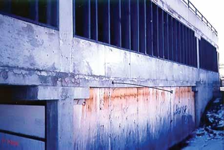
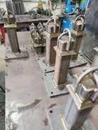
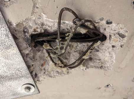
Corrosion of Post-Tensioned Strand Anchors Causing Strand Failure:
Unbonded post-tensioned strand reinforced concrete was used extensively in Alberta high-rise buildings from the 1960s to 1980s. Post tensioning is a method of reinforcing concrete in which steel strands are run through embedded sheaths, then tensioned after the concrete has been cast, providing additional strength to the structure. Post-tensioning can be located within beams, roof slabs and floor slabs. Anchors are a critical component of the system. Live end anchors are where the tension is applied to the strands during construction. These anchors are located at the slab edges and are subsequently covered with grout. Nowadays, the anchors are carefully waterproofed, a lesson learned too late for many buildings.
Water can enter the live end anchor pocket and strand sheathing if the waterproofing is lacking or fails. The strand sheathing holds moisture. Exposed to this moisture, strands and anchors corrode, which can result in significant structural damage and pose a risk to building occupants. The sudden release of tension in a failed strand causes other strands to bear the additional load, potentially causing them to fail as well. Signs of post-tension strand failure may include cracking
or bulging of concrete members, loud intermittent bangs as the tension of a strand is released, or the sudden appearance of deflection.
Preventing moisture infiltration is key to mitigating the risk of post-tensioned strand and anchor failure. Proper envelope detailing, including the use of flashing, sealants and moisture barriers, can help prevent moisture penetration and subsequent corrosion. Regular maintenance and inspection of the envelope system as well as the post-
30 AN ABECN/ABECS PUBLICATION
The energy released during strand failure caused the anchor and strand to erupt from the building slab edge.
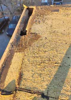
A Stramit deck collapsed from moisture damage at the corner of a Calgary wood-framed multi-unit residential building.
The strand formed a “birdcage” at an inspection release as a result of the sudden energy released during strand failure.
tensioning system will help identify potential points of moisture infiltration and strand failures and will allow for early intervention before significant damage occurs.
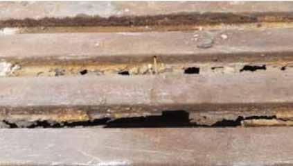
Susceptibility of Stramit (Compressed Straw) Roof Decks to Moisture Damage:
Compressed straw Stramit panels were an economical and environmentally friendly option for building Albertan roofs in the 1960s and 1970s, particularly in woodframed warehouses and low-rise multiunit residential buildings. Stramit panels consist of straw compressed between two organic paper facers and were used as the roof deck structure. Lightweight, porous, organic decks are inherently susceptible to moisture damage, which can cause them to deteriorate and compromise the integrity of the roof system.
When exposed to moisture, compressed straw Stramit roof decks can become soft and spongelike, losing their structural integrity, not too dissimilar to the failure of oriented strand board. By the time moisture is visible on the inside of the building, the structure may already be incapable of supporting the original design loads. Stramit decks are unlikely to meet the lateral load capacity required by modern code, and structural engineers have a lack of information available to guide repair strategies. Damage to the Stramit panels could push building owners into unexpected full-scale structural retrofit.
Proper installation and diligent maintenance of the roofing system can help prevent moisture infiltration and subsequent damage to Stramit panel roof decks.
Conclusion:
To make informed asset management decisions, it is essential to have a multi-disciplinary understanding of the roof, envelope and structural systems susceptible to moisture damage. As materials and construction methods change over time, subject matter experts from various disciplines, including
property management, architecture, engineering and construction, need to collaborate to update their knowledge and share lessons learned. The historical knowledge held by these experts is invaluable for mitigating risks and avoiding potential issues during a building service life. n
THE BUILDING RESTORATION SPECIALISTS
ALBERTA BUILDING ENVELOPE COUNCIL / NORTH & SOUTH CHAPTERS 31 6230 48 Street SE, Calgary, AB T2C 4P7 (403) 462-6633 | jonathanm@restorersgroup.ca #101, 10813 182 Street, Edmonton, AB T5S 1J5 (780) 239-6760 | dean@restorersgroup.ca
Building: Renfrew House • General contracting and specialty solutions • Heritage restoration and maintenance • Glazing, caulking, weatherproofing • Concrete, masonry, wall systems • Highrise and lowrise experience
MEETING NECB 2017 WITH MASONRY VENEERS
By Mark Hagel, PhD, PEng
Author bio: Dr. Mark Hagel Holds a bachelor of science in actuarial science and applied mathematics, a bachelor of science in civil engineering and a doctor of philosophy in civil engineering all from the University of Calgary. Prior to employment with the Alberta Masonry Council, Hagel worked for the Canadian Concrete Masonry Producers Association and as a building envelope engineer and structural engineer with the Calgary office of Halcrow Yolles.
Hagel’s fields of expertise include thermal and hygrothermal modeling of building systems, corrosion modeling, structural analysis and design and the durability of building components.
In 2018, Hagel served on the National Research Council of Canada’s (NRC) working group that developed the Guideline on Design for Durability of the Building Envelope and in a working group on the CSA-S478-2019 Durability in Buildings.
He has also taught first-year engineering courses as a sessional professor at both the University of Calgary and Mount Royal University.

Masonry is a 5,000-yearold building technology that has been proven to perform in all types of built environments because of its inherent resistance to fire, insects and moisture degradation. However, the design requirements for buildings have expanded from simply providing shelter to include maximizing the use of space, sound and light while minimizing the use of energy and reducing the carbon footprint. Like other cladding materials, masonry must adapt to meet modern construction
requirements that include exceptional thermal performance, effective moisture management and more-efficient use of space.1 The latest version of Canada’s National Energy Code for Buildings (NECB) that is currently enforced in Alberta is the NECB 20173. NECB 2017 requires more extensive modelling to account for thermal bridging than the preceding versions, NECB 20114 and NECB 2015.5
This article1,2 will explore techniques to meet the increased thermal performance for full-bed masonry veneers as well as adhered thin masonry veneers, such
32669 BEE BC 3/31/08 2:19 PM Page 1
as adhered thin brick and adhered thin natural and manufactured stone veneers. The article also discusses the use of the “simple trade-off” compliance path in NECB 2017 and its application to some traditional masonry elements, such as school gym walls and walls for light industrial low-rise buildings. These types of structures typically have low fenestration-and-door-to-wall ratios (FDWRs) and simple rectangular geometry. Using the prescriptive trade-off compliance path in NECB 2017 for the opaque wall and the glazing in these low FDWR buildings can help reduce
Anton J. Vlooswyk, P.Eng.
Cel:(403) 651-1514
Tel:(403) 287-0888
Fax:(403) 287-0880
Email:anton@beei.ca
Tel: (403) 287-0888
102,4029-8th Street S.E.
Calgary,Alberta,T2G 3A5
Email: admin@beei.ca
www.beei.ca
102, 4029- 8th Street S.E.
Calgary, Alberta, T2G 3A5 www.beei.ca
32 AN ABECN/ABECS PUBLICATION
Office 780-482-0578 Cell 780-993-6052 www.northernexposuredecking.net Specializing in waterproof PVC decking membranes: • Decks • Balconies • Roof decks 15817 121 A Ave NW, Edmonton, AB T5V 1B1 GET THE EXPERIENCED CHOICE Edmonton’s choice for builders, contractors & property managers Providing Building
Services
Western Canada Since 1987 BUILDING
INC.
• DESIGN • INSPECTION • TESTING SERVICES
Envelope Consulting
Across
ENVELOPE ENGINEERING
CONSULTING
Your ACSA helps you create a safer workplace.
We equip health and safety leaders with quality training, Certificate of Recognition programs, and professional designations.
Learn in the way that works for you:
• In-person classes
• Virtual instructor-led training (vILT)


• On-demand, online courses

Build the best management system for your team:
• Certificate of Recognition (COR)
• Small Employer Certificate of Recognition (SECOR)
• Temporary Letter of Certification
Earn your safety designation:
• National Health and Safety Administrator (NHSA)
• National Construction Safety Officer (NCSO)

Find us at: YourACSA.ca Publication: Building Science Perspective (ABEC)
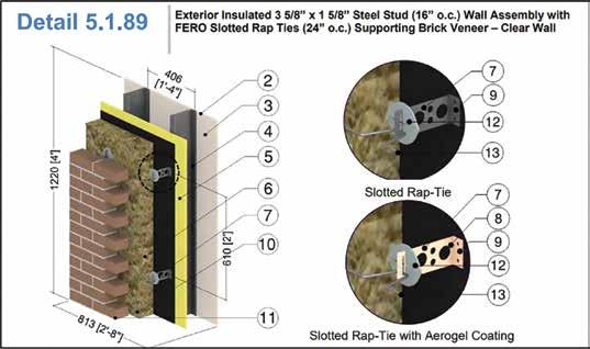
the insulation demand resulting in more cost-effective designs. The article also discusses improvements to thermal bridging values with the use of shelf angle stand-offs (knife plates) and surface mounted thermally broken brick ties that have been incorporated into an Online Masonry Thermal Catalog Application (https://docs.mecsimcalc.com/blog/ masonry-calculators-2022). The use of this online application can reduce the depth of insulation in a masonry veneer to meet the same R-value target by using more accurate thermal bridging values for masonry veneers that use surface mounted ties and shelf angle stand-offs.
NECB 2017 prescriptive path –simple trade-off method
As with previous versions (NECB 2011 and NECB 2015), the NECB 2017 permits trade-off between opaque wall components and less energy efficient fenestration and door components under the prescriptive path. However, where the NECB 2011 permitted trade-off between any component in the building envelope (e.g., roof insulation could be traded against wall insulation), the NECB 2017 only permits trade-offs between components in the
same orientation. For example, NECB 2017 permits trade-off of fenestration and thermal demand between abovegrade walls on different elevations (vertical orientation) but does not allow increased thermal efficiency of a roof (horizontal orientation) to reduce the insulation demand of the walls (vertical orientation).
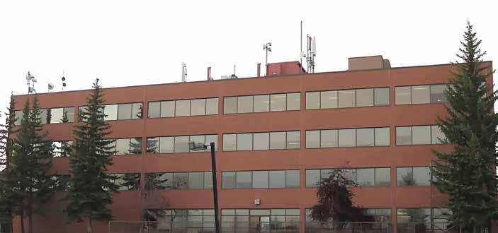
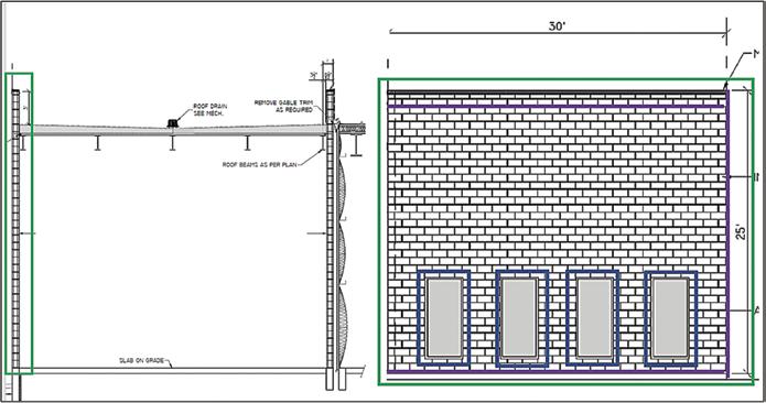
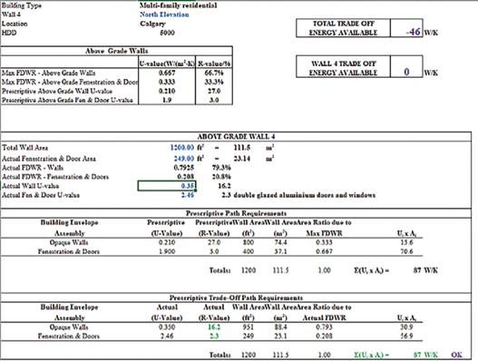
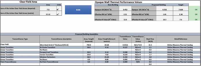
The simple trade-off method compares the total thermal transmittance (U-factor) through a component (area of the component) of the proposed building to the thermal transmittance through that same element in the proposed building designed according to the prescriptive requirements provided by the NECB 2017. By using a smaller FDWR than the prescriptive FDWR for a particular geographic location, the insulation demand of the opaque wall can be reduced below the insulation demand of the prescriptive requirement because fenestration has much larger thermal transmittance targets (i.e. 1.9 w/m2K) than opaque walls (i.e. 0.210 /m2 K). The simple trade off method is best illustrated with an example. In this example, an office building located in Calgary, Alt. has an elevation as presented in Figure 1.
The number heating degree days
(HDD) for this location is 5000 which, according to NECB 2017, yields an FDWR of 0.333 (33.3 per cent). For this location, the prescriptive requirement for the opaque walls is a U-factor of 0.210 (R-27) while the fenestration and doors must have a U-factor of 1.9 (R-3.0). The translation of these requirements is that, for any building under consideration located in Calgary that has 33.3 per cent of the wall area comprised of glazing and doors with an R-value of R-3.0, the required opaque wall R-value is R-27. The dimensions for the total wall of the elevation in Figure 1 equate to a wall area of 43.9 metres (144 feet) long by 13.4 metres (44 feet) tall, which equals a total wall area of 588.63 m2 (6336 ft2). The window bands are 7.09 metres (23.3 feet) wide by 1.6 metres (5.3 feet) tall in elevation. On the main floor of this elevation, there are 2.6 metres (8.8 feet) tall doors and windows. This translates into a FWDR of 0.243 (24.3 per cent). The smaller FWDR will result in a larger permissible U-factor for the opaque walls (and smaller R-value for the opaque walls).
The opaque wall area and fenestration area are simply multiplied by their prescriptive U-factors for this building. This calculation provides the prescriptive
34 AN ABECN/ABECS PUBLICATION
Figure 1. Calgary office building – elevation.
maximum energy consumption (heat loss) of the walls in watts/kelvin (W/K) and cannot be exceeded when the same opaque wall area and fenestration area are multiplied by the actual buildings U-factors. Mathematically, this can be
expressed as:
(Ui ,actual building x Ai, actual building ) < (Ui, prescriptive x Ai, actual building) – Equation 1
In Equation 1, Ui is the U-factor of the
component (in units of W/m2 K) and Ai is the area of the component (in units of m2). Equation 1 is more efficiently calculated using a spreadsheet as can be seen in Figure 2. When performing the calculations, it is best to start by selecting the R-value of the fenestration and doors as the values are typically fixed. The opaque wall value U-factor (and resulting R-value) can then be determined by increase the U-factor beyond the prescriptive value until the value on the left side of Equation 1 is less than or equal to the right side. In the example in Figure 2, by utilizing an improved thermally broken doubleglazed windows and doors of R-2.5 translates to a required R-value for the opaque walls of R-20.
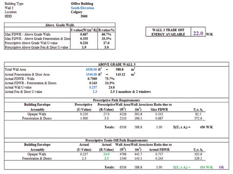
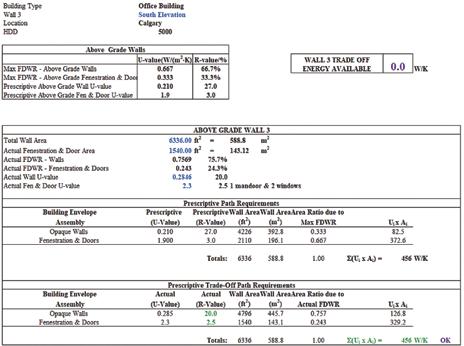
In Figure 2, the prescriptive tradeoff path with R-20 walls and R-2.5 windows and doors equates to a heat transfer through the total wall area of 456 W/K, which is less than or equal to (in this case equal to) the permitted prescriptive requirement of 456 W/K. Alternatively, the wall R-value could be increased and traded to another elevation with a larger FWDR to provide a consistent insulation demand for all walls of all elevations. In Figure 3, using the same R-2.5 windows and doors but increasing the R-value of the walls to R-24 results in a total heat transmittance of 434 W/K.
In this case, 434 W/k is 22.0 W/K less than the permitted 456 W/K heat loss (energy consumption of the system). This 22.0 W/K can simply be added to the “prescriptive path requirements total” of a wall on another elevation or subtracted from the “prescriptive trade off path requirements total.” The increase in 22.0 W/K could permit a larger FDWR (more glazing) on an identical elevation (FWDR = 27.9 per cent instead of 24.3 per cent).
ALBERTA BUILDING ENVELOPE COUNCIL / NORTH & SOUTH CHAPTERS 35
Figure 2. Energy balance for NECB 2017 simple trade-off compliance between walls and glazing on a commercial steel stud brick veneer building.
Figure 3. Energy balance for NECB 2017 simple trade-off compliance between walls and glazing on a commercial steel stud brick veneer building.
Full-bed masonry veneer examples
Now that the simple trade-off method has been discussed, techniques to comply with NECB 2017 requirements using full-bed masonry veneers can be explored. One of the most common forms of full bed masonry veneers is their use in the construction of wood-framed, multi-family residential
Equation 2 [5] where
UT = the total effective thermal transmittance (W/m2 K)
Uo = the clear field thermal transmittance (W/m2 K)
ATotal = the total opaque wall area (m2)
= the heat flow from a linear thermal bridge (W/m K)
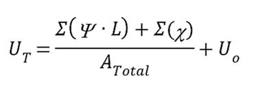
L = the length of the linear thermal bridge (m) = the heat flow from a point thermal bridge (W/K)
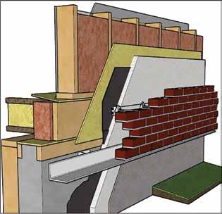
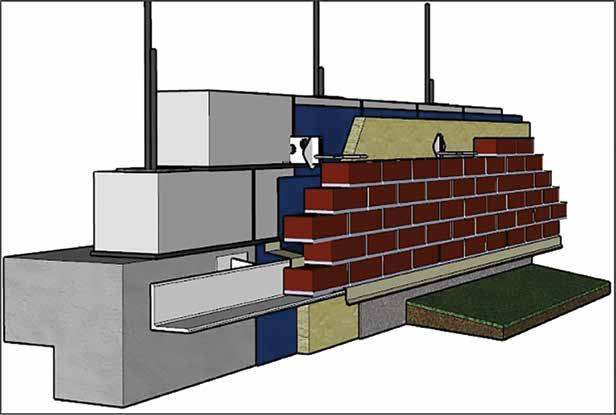
buildings. Figure 4 provides an example of this type of construction as illustrated in a 3D isometric foundation detail.
Typically, the walls are constructed of 2x6 spruce-pine-fir (SPF) dimension cut lumber, insulated between the studs with glass fiber batt insulation. The vapor barrier is typically a 6-mil polyethylene sheet installed between the studs and
the interior sheathing (typically 13 millimeters [½ inch] drywall) and a weather-resistant membrane (typically two layers of 30-minute building paper) installed over the exterior grade sheathing (typically 10 millimeters [3/8 inch] OSB). Cavity insulation, a 25-millimeter (one inch) air gap, and the 90 millimeter (3-5/8 inch) thick
36 AN ABECN/ABECS PUBLICATION
Figure 4. Wood-frame brick veneer wall assembly –foundation detail.
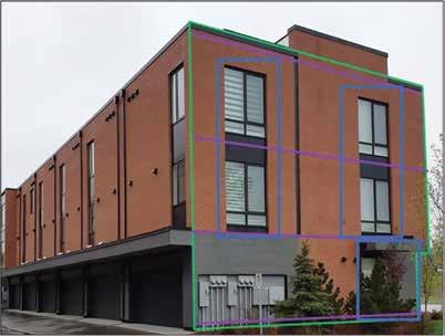
Figure 5. Wood-framed multi-family residential building example.
Figure 6. U-factor and -values for 2x6 wood frame wall with R19 batt and R5 exterior insulation as obtained from the online masonry thermal catalog application. (https://mecsimcalc.com/app/1652032/bvws_thermal_catalog_app)
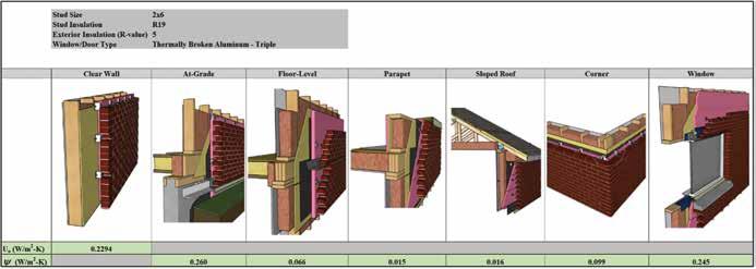
brick veneer tied to the structural wall with metal brick ties complete the system (Figure 4). In Figure 5 (below), the elevation outlined in green is used as an example to illustrate the thermal bridging calculations required to comply with NECB 2017.
The familiar equation used to aggregate the clear field and bridging components into a composite U-factor is given on the previous page.
This equation has been conveniently integrated into a spreadsheet (Figure 7) that can be used with a catalogue of thermal details from a prominent
Canadian building engineering firm6 and complimented by the recently released online masonry thermal catalog (Figure 6) that includes details not found in other thermal catalogs. The thermal bridging values that were input into the spreadsheet in Figure 7 were taken from the online masonry thermal catalog values found in Figure 6.

In the example in Figure 5, the building elevation has the various thermal bridging elements identified by colour. The green outline identifies the clear field wall area for the Uo calculation; the purple lines identify the horizontal
linear thermal bridges formed at the foundation, floor levels and roof transition, while the blue rectangles identify the linear thermal bridges from the fenestration and doors. A vertical linear thermal bridge must also be accounted for at one of the corners of the elevation. Assuming a wall construction that is 2x6 with R19 batt and two inches of external expanded polystyrene (EPS) insulation, Figure 7 aggregates these components, which have a clear field R-value of R-27.5 that reduces to an effective R-21.6 when thermal bridging effects have been included. In this case, the use of
ALBERTA BUILDING ENVELOPE COUNCIL / NORTH & SOUTH CHAPTERS 37
SUITE 300, 6 ROSLYN ROAD, WINNIPEG, MANITOBA, CANADA www.delcommunications.com WE OFFER OUTSTANDING PERSONAL SERVICE AND QUALITY IN THE AREAS OF... • Creative design • Advertising sales • Trade publications • Qualified sales & editorial team DEL Communications Inc. Your key to success.
Figure 7. Wood-framed multi-family residential building example – effective R-value accounting for thermal bridging effects.
the simple trade-off system would be required for the wall system to comply with NECB 2017 in locations of Canada that have Heating Degree Days (HDD) exceeding 4000. As the actual building in Figure 5 is in Calgary, Alt., which has an HDD of 5000, the trade-off system was used to determine the level of insulation required to comply with NECB 2017. Figure 8 illustrates that, when trade off is applied with the use of R-2.3 windows and doors, the walls on this elevation require only R-16.2 and the two inches of external EPS is sufficient. This is because the actual FWDR of the elevation in Figure 5 is only 20.8 per cent where the prescriptive allowance for buildings located in Calgary is 33.3 per cent.
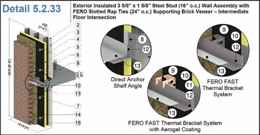
Another example where masonry veneer is typically used is in warehouse and light industrial building (WILB) applications. One
38 AN ABECN/ABECS PUBLICATION
Figure 8. Wood-framed multi-family residential building example – trade-off R-value accounting for thermal bridging effects.
Figure 9. Concrete block brick veneer wall assembly.


ALBERTA BUILDING ENVELOPE COUNCIL / NORTH & SOUTH CHAPTERS 39
ADVANCED PERFORMANCE ANALYSIS BUILDING ENVELOPE BUILDING RESTORATION BRIDGE ENGINEERING CONSTRUCTION ENGINEERING FIRE ENGINEERING PEDESTRIAN MODELLING SPECIAL PROJECTS STRUCTURAL ENGINEERING SUSTAINABLE BUILDING CONSULTING TRANSPORTATION STRUCTURES entuitive.com VANCOUVER | CALGARY | EDMONTON | TORONTO | OTTAWA | NEW YORK We deliver uncompromising performance. We are Entuitive. NEOMA (FORMERLY SIERRA PLACE) CALGARY, AB CALGARY 403-471-3492 | EDMONTON 780-884-7378 VISIT US ONLINE KELLERENGINEERING.COM PROTECTING PEOPLE’S BUILDINGS RESTORATION CONSULTING NEW CONSTRUCTION INVESTIGATIONS AND TESTING INSPECTIONS ROOFING CONSULTING CONDITION ASSESSMENTS
Figure 10. Concrete block-brick veneer wall assembly – foundation detail.
elevation of an addition to an existing building using a concrete-block structural wall and brick veneer is provide in Figure 9. In Figure 10, a typical example of this type of concrete-block structural wall with brick veneer is illustrated in a 3D isometric at the foundation.
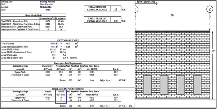
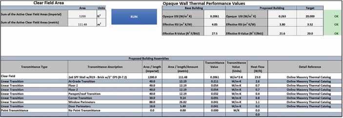
Assuming a location for this building in a milder climate of 4500 HDD, a target of R-23.0 is required. The simple trade-off path between fenestration and opaque wall can again be applied to reduce the insulation demand in the wall assembly because there is little fenestration on
the elevation in Figure 9. For this elevation of the building, trading-off actual fenestration of 12.7 per cent to the prescriptive allowance of 36.4 per cent results in a wall insulation requirement of (after accounting for thermal bridging effects) of R-7.6 (RSI = 1.33) when R-2.3 (RSI = 0.4) fenestration is used (Figure 11).
In Figure 9, the building elevation is once again broken into its various thermal bridging elements, which are identified by colour: the green outline identifies the clear field wall area for the
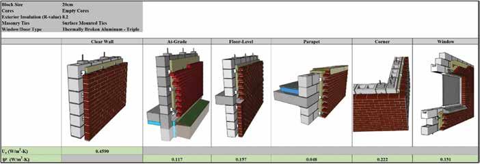
Uo calculation; the purple lines identify the linear thermal bridges formed by the foundation, wall-corner and roof transitions; and the blue rectangles identify the linear thermal bridges from the windows. Assuming a 20cm concrete block wall with brick veneer wall and two inches of mineral wool exterior insulation (R-8.2) for the wall construction, the required values for the clear field and linear transmission values can be obtained with the online masonry thermal catalog app (Figure 12).
40 AN ABECN/ABECS PUBLICATION
Figure 11: Simple trade off calculation for concrete block brick veneer building addition.
Figure 12. U-factor and -values for 20cm concrete block wall R8.2 exterior insulation as obtained from the online masonry thermal catalog application. (https://mecsimcalc.com/app/6855626/bvcu_thermal_catalog_app).
Figure 13 aggregates these thermal bridges with the clear field, which has an R-value of R-12.6, that reduces to an effective R-10.3 when thermal-bridging effects have been included.
The wall assembly’s R-10.3 exceeds the required R-7.6 from the trade off calculation and provides the necessary insulation with only 51 mm (two inches) of mineral-wool insulation.
Innovations in masonry to reduce the impacts of thermal bridging
Recent advances in the masonry industry introduce stainless steel, glass-fiber-reinforced polymers (GFRP) and Aerogel coatings to masonry ties and shelf-angle stand-offs have reduced the thickness of exterior insulation required to achieve the same thermal performance
ALBERTA BUILDING ENVELOPE COUNCIL / NORTH & SOUTH CHAPTERS 41
Figure 13. Block warehouse extension example – effective R-value accounting for thermal bridging effects.
Figure 14: Steel stud brick veneer example – slotted rap tie with Aerogel coating. [6]
Figure 15: Steel stud brick veneer shelf angle – slotted rap tie with Aerogel coating. [6]
when compared with the use of these components fabricated with traditional steel. Figure 14 and Figure 15 illustrate typical details with Aerogel coated ties and thermally efficient shelf angle standoffs. A thermally broken shelf angle using an Aerogel covered standoff drops the value from 0.322 W/m K (with typical steel) to 0.074 W/m K (Figure 15) for an R-16.8 exterior insulation.
Another area where efficiencies can be
found is the use of surface mounted ties with concrete block backup walls. Concrete block back-up walls typically use ties that are embed into the head joint of the block (Figure 16 a.). When these ties are made of steel, there is significant thermal bridging.
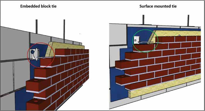
A recent 3D thermal model demonstrated that using surface mounted ties (Figure 16 b) results in an increase in thermal performance
of approximately 10 per cent in the clear field wall (Uo). These thermal performance improvements to concrete block and brick veneer walls can translate up to an RSI = 0.9 (R-5) improvement in the wall performance without the addition of more insulation.
Adhered thin masonry veneer examples
Requirements of NECB 2017 to include thermal-bridging effects of wall corners,
42 AN ABECN/ABECS PUBLICATION
Figure 16: a) Embedded block tie, b) surface mounted tie.
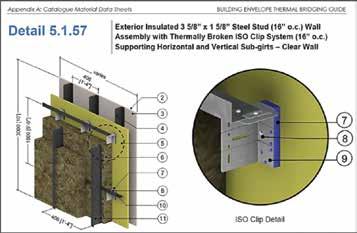
Figure 17. Exterior insulated steel stud wall assembly clad with adhered manufactured thin stone masonry veneer.
Figure 18. Exterior insulated steel stud wall assembly (Morrison Hershfield Thermal Catalog) capable to receive adhered thin masonry veneers6.
floor levels, at grade and parapets, and around fenestration and doors have led to the addition or increase in thickness of exterior insulation. To reduce the overall thickness of the wall, thin masonry veneers are being used more frequently with exterior-insulated steeland wood-stud systems. Thin masonry veneers are typically 1/3 to 1/4 the of the thickness of full-bed masonry veneers. For example, thin brick units are typically between 13 mm to 25 mm (1/2 inch to one inch) thick where full bed brick units are 90 mm (3-5/8 inch) thick. Thin adhered manufactured stone unit thicknesses are between 13 mm and 66.7 mm (1/2 inch and 2-5/8 inches) thick as per ASTM C1670-19,7 where traditional full bed stone units are 100 mm (four inches) thick. These thin alternatives to traditional masonry are attractive options to reducing the overall thickness of the wall if property lines and useable space constrain the wall thickness.
Using thermally broken clip systems can further improve the performance of the wall and reduce the thickness of insulation required in the wall assembly.
Figure 17 provides an illustration of a thermally broken clip system attached to a steel stud back-up wall that is supporting a black-coloured adhered manufactured stone veneer.
Figure 18 provides the detail in the thermal catalog that could be used in conjunction with the spreadsheet to determine the overall thermal performance of the wall. In Figure 18 no cladding is specified; however, the contribution to overall thermal performance from the thin stone veneer is less than R-0.1 (RSI = 0.018) and can be considered negligible.
Conclusion
Several examples of the ability of masonry veneers to comply with NECB 2017 requirements were discussed.

The techniques typically involve the use of the simple, prescriptive tradeoff path that can offset the insulation demand increase when thermal bridging of fenestration, floor level, at grade, parapet and wall corner transitions are accounted for, as required by the NECB 2017.
Increased thermal performance of masonry veneers with the use of
stainless steel, Aerogel coated masonry ties and shelf-angle stand-offs were identified as emerging innovations that are being introduced to the market to further increase thermal performance of masonry veneers in the clear field, floor, parapet, wall corner and at-grade transitions. Several of these technologies are already available.
The increase in insulation requirements
Efficient strategies for high performing buildings


As an integrated practice of engineers, architects and specialists, our team has pioneered many aspects of the building science field. We bring more than 40 years of proven experience with nearly all types of buildings and their respective building envelope systems, assemblies and components.
100+ 40+ 1st
ALBERTA BUILDING ENVELOPE COUNCIL / NORTH & SOUTH CHAPTERS 43 exp com
BUILDING SCIENCE PROFESSIONALS YEARS IN BUILDING SCIENCE FACILITY FOR DYNAMIC WIND UPLIFT TESTING FOR ROOFS IN NORTH AMERICA
has led to an increase in the thickness of the walls. Where property lines or useable interior space present a constraint in the wall thickness, adhered masonry veneer units provide an alternative to traditional full-bed masonry veneer units that are typically less than half the thickness of full bed masonry veneer units. As a result, adhered masonry veneers can provide
the masonry aesthetic with a fraction of the thickness. This option is easily thermally modelled with existing details in thermal catalogs when the contribution of the masonry veneer is ignored. Given the negligible R-value contribution provided by the adhered masonry veneer to the overall thermal performance of the wall this assumption is reasonable.

Committed to the future of heritage.
References
[1] Hagel, Mark, D., “Adapting Masonry Veneers to Comply With NECB”, Interface – The Technical Journal of the International Institute of Building Enclosure Consultants, Vol. XXXVIII, No. 11, November 2020.
[2] Hagel, Mark, D., “Meeting the National Energy Code Requirements with Masonry”, Construction Canada Magazine, Vol. 58, No. 9, Kenilworth, December 2016.pg 36-44.
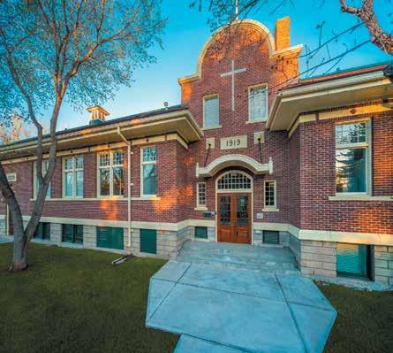
[3] National Energy Code for Buildings (NECB) 2017, ISBN 0-660-243214, National Research Council of Canada, Ottawa, 2017.
[4] National Energy Code for Buildings (NECB) 2011, ISBN 0-660-243214, National Research Council of Canada, Ottawa, 2011.
[5] National Energy Code for Buildings (NECB) 2015, ISBN 0-660-243214, National Research Council of Canada, Ottawa, 2015
[6] Morrison Hershfield Ltd., “Building Envelope Thermal Bridging Guide v1.4”, BC Hydro Power Smart, Vancouver, 2020

[7] ASTM-C1670-18a Specification for Adhered Manufactured Stone Masonry Veneer Units, American Society for Testing and Materials International Pennsylvania, United States of America, 2018 n
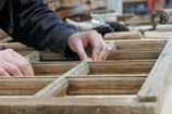
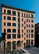
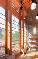

44 AN ABECN/ABECS PUBLICATION
CHC is a proud dealer for
Marvin Windows- New Construction Marvin Windows- Historic
Historic Holy Angels window conservation - Calgary, AB
Chalmers Heritage Conservation Ltd. specializes in the conservation of historic places across Western Canada
PLEASE RECYCLE
SHAKESPEARE DOES ROOFS
Courtesy of Joseph Lstiburek, Building Science Corporation. Visit www.buildingscience.com for more Insights.
To vent, or not to vent…that is the question: Whether ‘tis nobler in the mind to suffer The slings and arrows of outrageous moisture,
With apologies to the Bard of Avon, after several decades of dealing with roofs I have come to the answer to the roof vent question: do not vent… except. Great answer, eh?
Vented roofs blow off more than unvented roofs. Vented roofs burn more than unvented roofs. Vented roofs are energy inefficient compared to unvented roofs. Vented roofs cause moisture problems south of the Mason-Dixon Line and east of Interstate 35 in Texas. Venting a roof in a hot-humid and mixed humid climate is a very, very bad idea.
The only time you should vent a roof is to control icedamming. And when I do a vented roof to control icedamming I install the vented roof over the top of an unvented under-roof.
The original reasons to vent roofs were pretty reasonable. In cold climates roofs were vented to control moisture accumulation and… yes… to control ice-damming. In hot climates roofs were vented to increase thermal comfort. In cold climates roof venting-controlled attic moisture accumulation only in poorly insulated attics. Let me repeat that to have it sink in. Roofs needed to be poorly insulated. In the winter the air outside is cold. Yup. Cold air is not capable of holding much moisture. So bringing cold air into your attic does not remove moisture unless there is heat loss from the building. The heat loss warms up the incoming cold air giving it the ability to pick up moisture and carry it to the outside. All the attic ventilation retios – one to 300, one to 150 were based on little or no insulation. The code now calls for R-60 in attics. There is no effective heat loss from the building into the attic. It gets worse, the relative humidity of the outside air is very
Or to take arms against them
And by opposing end them. To rot – to rust, To rust perchance to scream – ay, there’s the rub.
high – vapor pressure is low – hygroscopic materials like wood, plywood and OSB “see” relative humidity not vapor pressure. Venting highly insulated roofs in cold climates actually makes them wet. LOL.

You want to have some fun, ask a Canadian about how well the CHIP program worked in the 1980’s. Oops… has to be
www.maydayinspect.ca
ALBERTA BUILDING ENVELOPE COUNCIL / NORTH & SOUTH CHAPTERS 45
• Large Building Air Tightness Testing • Building Investigations • Thermography • Residential Inspections
(780) 991-5260 info@maydayinspect.ca
an old Canadian. CHIP was the short form for “Canadian Home Insulation Program” that came out of the first energy crisis. Everyone got a couple of hundred dollars to insulate attics. Guess what? The attics got colder. Stopped the heat from getting into the attic, but not the moisture. Roofs rotted (Photograph 1 and Photograph 2). More oops. To stop the moisture, we needed to air seal the attic ceilings. Canadians did it first, and best (Photograph 3). Even more oops. Moved the moisture problem to the building underneath because air
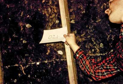
change in the building was reduced. It sometimes got real bad, caused spillage and back drafting of combustion appliances and folks died from carbon monoxide poisoning. Had to install sealed combustion or power vented combustion appliances and provide controlled mechanical ventilation.
In hot climates, back in the day, you were not actually venting the roof, you were venting the building under the roof through the roof bringing in outside air to the occupied space and
removing inside air up through the attic to the exterior. This worked before we had something called air-conditioning. With air conditioning venting roofs sucked air conditioned air out of the building. The only way to not suck air conditioned air out of the building when venting the roof is to air seal the attic ceiling. Yup, ended up with spillage and backdrafting in the U.S. Civilians had a better understanding than most experts. When they installed attic turbine vents (Photograph 4) and they found that their air conditioning bill would go up they
46 AN ABECN/ABECS PUBLICATION
Photo 1: Roof Rot – OSB does not come that color when it comes from the factory.
Photo 2: More Roof Rot – Frost on nails and roof sheathing.
Photo 3: A Young Guy – Yes, me in 1982 pointing out how to seal attic ceilings
Photo 4: Turbine Vents – Typically lead to increased air conditioning bills.
Photo 5: Civilian Solution – Plastic garbage bag handles the turbine vent problem.
had a simple fix (Photograph 5). You want to have some fun, ask an American about how well the Weatherization program worked in the 1990s. Oops… has to be an old American. Pretty sure Canada exported the technology to the U.S. to get even for Canada-U.S. Free Trade Agreement. Weatherization folks discovered controlled ventilation and combustion safety.
Even if you air seal the attic ceiling, and you handle combustion safety, and you provide controlled ventilation in the occupied space, venting a roof in a hot-humid and mixed humid climate causes moisture problems because the air outside is humid. Note the “humid” in “hot-humid” and “mixed humid” climate.
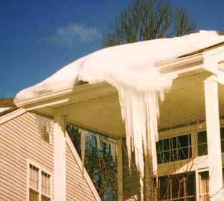
Something that should be obvious is not always obvious. Vented roofs blow off more than unvented roofs. Significant air pressure differences act across buildings due to the action of wind. In general building assemblies experience positive wind pressures on the windward side and negative wind pressures on the leeward side. This includes sloping roof assemblies. Attic spaces that are ventilated typically have soffit ventilation. Soffit assemblies are not able to withstand high wind events. When soffit assemblies collapse in high wind
events, wind can enter the attic space on the windward side pressurizing the attic space. When this attic positive air pressure is coupled with the negative pressure on the exterior surfaces of the leeward side of the building the air pressure difference across roof sheathing and roof cladding elements such as shingles, tiles and metal roofing significantly increases. This significant air pressure increase can lead to loss
High Performance Engineering Services
Building Enclosures

Building Energy Modelling
Façade Engineering
Waterproofing
Investigations & Evaluations
of the roof structure. Roof assemblies that are not vented resist high wind events more effectively than vented roof assemblies because there is less risk of soffit collapse.
As noted earlier, vented roofs burn more than unvented roofs. We were here before (“Wildfire,” ASHRAE Journal, August 2021). With respect to wildfires the issue is burning embers.
ALBERTA BUILDING ENVELOPE COUNCIL / NORTH & SOUTH CHAPTERS 47
RJC Engineers rjc.ca
Photo6: Classic Ice Dam – Can be prevented and controlled with ventilation.
Roofs are particularly prone to burn ember exposure – both from the perspective of the roof covering and from the perspective of roof venting. Entry of burning embers is a concern in urban regions with higher risk of wildfire occurrence. Homes built in regions designated as Urban Wildland Interface Zones are at a high risk for fire exposure. Wildfires burn with speed and intensity that often lead to a high percentages of homes lost in these communities. However, the ignition of homes is typically not caused directly by flames but rather by ignited embers becoming airborne and entering vented roof assemblies. Obviously, unvented roofs do not have this issue.
Also, as noted earlier, vented roofs are energy inefficient compared to unvented roofs. This is particularly the case where ductwork and mechanical systems are located in vented attics. Ductwork leaks and leads to negative air pressures, energy costs and part load moisture problems (Figure 1). An unvented conditioned roof solves this problem (Figure 2).
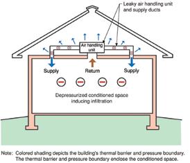
For decades, one of the arguments for venting roof assemblies is to “prevent shingles from being cooked.” This has been discounted in many papers. A good piece of work was done by Rudd in 2005 (Journal of Building Physics, October 2005). Rudd found that “the summertime average daily temperature of roofing materials is nearly unchanged whether vented or unvented, while short-term peak temperature increases are not more than 7 degrees F.” It is also obvious that the color of the roofing layer is more significant regarding temperature than venting or not venting. Now to the “except” part. The only time you should vent a roof is to control ice-damming (Photograph 6). We were here before (“Dam Ice Dam,” ASHRAE Journal, June 2010). Ice dams happen
when the outside temperature is below freezing, the roof deck temperature is above freezing and there is snow on the roof. The warm roof deck causes the snow on top of the roof deck to melt and the melt water runs down to the edge of the roof where the water freezes leading to a buildup of ice and a backup of water – hence the term “dam.”
The strategy to control ice dams is fundamentally straightforward – keep the roof deck below freezing when the outside temperature is below freezing. The best approach – the classic approach – to ice dam control is the vented roof. Keep heat from the interior from getting to the roof deck and then remove any heat that gets there using ventilation. So you want/need a vented roof to control ice-damming. Having said that, I install the vented roof over the top of an unvented under-roof (Figure 3). What about the issue with entry of burning embers? Operable vents that are closed when a wildfire event occurs.
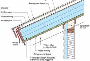
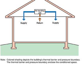
Whew! Had to get all of this off my chest. Venting therapy.
Bibliography
Lstiburek, J.W., “Learning from Mistakes,” ASHRAE Journal, February 2010
Lstiburek, J.W., “Dam Ice Dam,” ASHRAE Journal, June 2010.
Lstiburek, J.W., “Wildfire,” ASHRAE Journal, August 2021
Rudd, A., “Field Performance of Unvented Cathedralized Attics in the USA,” Journal of Building Physics, Vol 29, No. 2, October 2005
https://buildingscience.com/ sites/default/files/migrate/pdf/ PA_Rudd_Journal%20of%20 Building%20Physics%20Unvented%20 Cathedralized%20Attics.pdf n
48 AN ABECN/ABECS PUBLICATION
Figure 1: Vented Roofs - Vented roofs are energy inefficient compared to unvented roofs. This is particularly the case where ductwork and mechanical systems are located in vented attics. Ductwork leaks and leads to negative air pressures, energy costs and part load moisture problems.
Figure 3: Vented Over Roof Over an Unvented Under Roof Roof – Note that the air intake for the vented “over-roof” is at the facia and that the overhang is insulated compensating for cladding thermal plumes due to incident solar radiation.
Figure 2. Unvented Roof - An unvented conditioned roof solves the problem of duct leakage and negative pressure.
SPRING HAS SPRUNG… A LEAK?
By Ryan Cornforth, RRC

Aroof is like a pen.
If you have a good one you probably never really think about it, but when you have one that’s not working properly, or has failed completely, it can leave you in an extremely tough spot. And often the implications aren’t noticeable until you miss the meeting you were supposed to be writing down.
We take a lot of things for granted in this world, and we always have experts in their field telling us to take more preventative measures. Whether it’s your doctor telling you to get a few more hours of exercise a week, or your mechanic telling you to swap out your alternator fluid more regularly, we have a lot to take care of.
Add your roof to that list of items that need maintenance. Like most things noted above, maintenance is cheaper and much more effective in the long run than trying to deal with repairs. That said, as I write this, I’m hammering a Boston Cream doughnut so I’m not here to preach.
So, the question is, how do you maintain a roof with as little additional effort as possible? Easy answer, throw money at it! Ok, ok the real question is how do you maintain a roof with minimal additional effort, and limited additional costs? The answer is to focus on items that will return the best bang for your buck. Depending on your roof type there are some relatively low-cost maintenance items that will have large impacts on the long-term health of the roof. Think of these like an oil change on a car, it’s a necessary maintenance item, but it certainly won't guarantee that you get 300,000 kilometers out of the vehicle. Topping up gum cups, re-sealing curb corners and cleaning up debris once a year don’t sound like much and shouldn’t cost more than one to two per cent of the total roof value but can go a long way to ensure that you make it to the 10 year mark without any problems.
Good preventative maintenance will pay additional dividends during major rainstorms, or melts. During these times, the number of leaks outnumbers the number of qualified roofing technicians, no matter what company you are dealing with. Limiting the number of service requests you have to put in on those days, even by a small percentage, can have a ripple effect by allowing technicians to spend a few more minutes on the leak you do have, and possibly allowing for a better diagnosis. On top of that, leaks that occur during major rains or melts almost always require a return visit because making permanent repairs when water is pouring into the area is almost impossible in most cases. So avoiding some of those can be very financially beneficial as well.

When a roof is doing it’s job it should be the ultimate out of sight out of mind experience. Hopefully this article outlines some ways to achieve that experience, but if you’re looking for some additional information, I would recommend calling a qualified roofing consultant and getting them to help with a properly managed maintenance program. Organizations like IIBEC, ABEC and ARCA can help point you in the right direction. n

ALBERTA BUILDING ENVELOPE COUNCIL / NORTH & SOUTH CHAPTERS 49
• Residential / Commercial • Remodel • Custom Windows • Custom Doors • Performance Audits • Historical Repair • Repairs • Leak Investigation • Restoration 9505 - 56 Avenue, Edmonton, AB 780-434-9487 info@permasealwindows.com permasealwindows.com
THE REVAY CORNER: SO YOUR PROJECT HAS SPRUNG A LEAK… NOW WHAT?
By Suzanne Checkryn, P.Eng., PMP, MBA –Director, Prairies at Revay and Associates Limited

Author bio: Suzanne Checkryn is a professional engineer with more than 25 years of experience working in engineering, construction and consulting. Throughout her career, Suzanne has worked with major firms to complete projects on schedule and to overcome significant engineering and construction challenges. She has been involved in a variety of projects, including multibillion-dollar projects with complex engineering, supply chain, construction, project controls, risk management and change management requirements. Suzanne has extensive field experience working with owners, engineers, consultants, general contractors, subcontractors and suppliers.
At Revay, Suzanne is responsible for the firm’s Calgary office which services Alberta, Saskatchewan and Manitoba. She has been retained as expert for referee, mediation, arbitration and litigation. Suzanne also delivers training focused on claims avoidance and claims management to clients and industry associations across Canada and at the University of Calgary.
With spring comes the ramp-up of construction projects that may have slowed or paused over winter, along with the start of new projects. The construction industry will once again aim to take advantage of more favourable weather conditions. Where seasonal work can be done, construction costs can be lower, and higher productivity levels can be expected.
Whether you are well into your project or it is just getting started, spring marks a good time to stop and assess the health of your project. Key questions you and your project team may want to ask are: Has our project been set up for success? Is our project going as planned? Are we keeping good records? Has our project ‘sprung a leak?’ And if the project you
are working on has sprung a (literal or metaphorical) ‘leak,’ now what?
While there are numerous causes of literal leaks on construction projects, this column focuses on the metaphorical ‘leaks’ (i.e. risks or issues) that many projects face which result in delays, disruptions and cost overruns. In Revay’s experience, common issues such as incomplete designs/specifications, changed site conditions and unrealistic schedules/estimates continue to be prevalent. When you add to this current material pricing, supply chain and labour supply issues, it is even more important to prepare for and have a plan to deal with project risks and issues. Ideally projects can avoid issues, or mitigate their impacts, through measures such as investing additional time in design and planning activities and thoroughly assessing potential
risks. Failing this, projects will have no choice but to deal with (some or all of) the aforementioned issues. For example, if an owner has not adequately investigated site, material cost or supply risks, but has instead simply passed the risks on to the contractor, the risks have not been mitigated. While it is possible to transfer risk around a project, it is not possible to transfer risk off a project.
In Revay’s experience, knowing what risks/issues you may face ahead of time and dealing with issues as they come up usually results in a more favourable outcome. Utilizing contract mechanisms, such as the notice and change order provisions, whereby issues can be formally communicated, and contract price and will schedule can be appropriately adjusted and support the resolution of project issues in real-time. Avoiding or prolonging the resolution
50 AN ABECN/ABECS PUBLICATION
of issues creates more difficulty in (1) assessing delay and/or cost overruns, and (2) identifying which party bears responsibility for the delay and/or cost overruns. Waiting until later can also result in even higher costs and add strain to projects and relationships.
A project’s ability to deal with issues in real-time is greatly improved if detailed
records are being kept. The upkeep of contemporaneous records such as schedules, daily site reports, progress reports, meeting minutes, Requests for Information (“RFI”), photographs, logs (i.e., change order log; submittal log), correspondence and actual hours/costs allow for (1) better communication, and (2) readily available facts/data when issues arise. Taking time to document,
in detail, the specific issues you are facing and their impacts (cost, schedule, etc.) will also assist the project parties in expediently developing, reviewing and approving change orders. This will ultimately pave the path to more successful projects at a time when the construction industry is facing challenges that it must overcome together. n

ALBERTA BUILDING ENVELOPE COUNCIL / NORTH & SOUTH CHAPTERS 51
SUITE 300, 6 ROSLYN ROAD, WINNIPEG, MANITOBA, CANADA www.delcommunications.com THE KEY TO PUBLISHING SUCCESS. We offer outstanding personal service and quality in the areas of: • Advertising Sales • Trade Publications • E-newsletters • On-Line Directories • Websites • Qualified Sales & Editorial Team • Creative Design
Ideally projects can avoid issues, or mitigate their impacts, through measures such as investing additional time in design and planning activities and thoroughly assessing potential risks. Failing this, projects will have no choice but to deal with (some or all of) the aforementioned issues. For example, if an owner has not adequately investigated site, material cost or supply risks, but has instead simply passed the risks on to the contractor, the risks have not been mitigated. While it is possible to transfer risk around a project, it is not possible to transfer risk off a project.
Jamie Murphy is a principal with RJC Engineers. He has completed evaluations and restorations of numerous facilities and buildings. He is involved with the evaluation and restoration of new and existing projects ranging in size from single-storey wood buildings to high-rise concrete and steel buildings. He is involved in the preparation of tender and contract documents, contract administration and construction review. Jamie represented clients in arbitrations, mediations and judicial dispute resolutions. He has also served as an expert witness for several clients.
Jamie is currently a director for the Construction Specifications Canada (CSC) Northern Alberta Chapter and Alberta Building Envelope Council North Chapter (ABECN). He has been involved with teaching construction industry related professionals the CSC Level 1 Principals of Construction Documents course since 2002. Jamie is a past director for the Canadian Condominium Institute (CCI – North Chapter) board of directors and ASET board of examiners.
INDUSTRY EXPERT Q&A: JAMIE MURPHY
Jamie has presented on building science and restoration to groups such as the American Air Barrier Association (AABA) and Canadian Condominium Institute (CCI).
Jamie has achieved his accreditation with the Canada Green Building Council (CAGBC) demonstrating his knowledge of the green building design and construction industry in Leadership in Energy and Environmental Design (LEED®).

We wanted to get to know Jamie a bit more so we asked him the following questions:
You are registered with APEGA, and building envelope is a relatively new discipline. How did you come to specialize in building envelope?
I have always had a passion for construction. I’ve been involved in new construction and building science and restoration for approximately 35 years. In addition to my engineering background, I hold a Journeyman Certificate in Carpentry which has been endorsed by a Red Seal. Being on the tools gives you a different perspective
and insight into constructability. Although it goes without saying, the skills I took away from school and my work ethic have been extremely important to my success. First principles, problem solving, organizing how to approach problems and tasks, how to manage time and thinking creatively are just a few skills that come up in my dayto-day work.
I have had some amazing experiences and worked with some remarkable professionals.
How long have you been principal of Read Jones Christoffersen Ltd., and what does your firm offer that differs from a typical building science consultant?
In 1998 I was interviewed by two Principals from RJC: Mr. Ted Stone and Mr. Gino Ferri. Following my interview with these two individuals, I was offered the position. It wasn’t hard to accept their offer after talking with them. Even in retirement these two people are still great mentors and leaders. I was offered a role in the leadership and management of the firm as principal in 2017.
52 AN ABECN/ABECS PUBLICATION
Today, RJC is the largest independent employee-owned engineering firm specializing in buildings across Canada and, more recently, we have seen offices open in the U.S. The people are what make us an exceptional firm. We share a passion for creative design, collaboration and superior client service. This is what empowers and inspires us daily.
In the past it was possible to construct a high-rise building with 10 or fewer architectural drawings. That is generally viewed as incomprehensible today. Is there a direct correlation between bigger drawing packages/more detailed design and quality of the building envelope?
It is important to remember that in the past drawings were created on sheets of large paper. Drafters would need different grades of pencil, erasers, t-squares, stencils etc. A lot of thought and care went into what was being put on any given drawing. Making changes after a drawing was completed took time and could be the difference between eating supper at home with your family and scrounging up an old bag of peanuts at the office while you make the change. It wasn’t until the 1990s that computer aided design (CAD) started in most offices. Drafting tables were replaced with computers, and pencils and erasers were replaced with a keyboard and mouse. This was when we started to see drawing sets expand. You didn’t need to put multiple things on one drawing. With CAD, you could create the same drawing multiple
times to illustrate specific items on each drawing. The building wasn’t any more complicated.
However, the construction industry has been evolving to meet a variety of challenges associated to client demands, project financing, decline in skilled labour, new and innovative materials, stricter regulations on safety, regulations and incentives for environmental controls, standardized building codes, new and emerging programs and technologies etc. Some of these are not new, but they are evolving. Many of these challenges are also making buildings more complicated and in turn require more from all the project participants if we hope to achieve a quality building envelope needed.
What advancement in technology has had the largest positive impact on the building envelope? Largest negative impact?
Computer aide design is not that old but it has, arguably, had the greatest positive impact on the construction industry.
Not all technology has been as positive as CAD. The introduction of email as a method of communication is not new to the world, but it is relatively new to the construction industry. It involves transmitting and receiving short uncomplicated messages using an electronic device. I say this all the time in the PCD course I teach: better communication technology doesn't mean you get better communication. Email has a lot of shortcomings and there have been many misunderstandings arising from it. People have placed so much dependence on communicating through
email that they are shocked when someone asks them to pick up a phone and call the person rather than email them.
Do you see (other) changes coming in the way we construct buildings and the building envelope?
Artificial intelligence is playing a larger role in the construction industry. Change in the construction industry usually takes a bit of time to take hold, but once it does, it gains momentum quick. Automated planning and scheduling, robotics such as 3D printing, knowledge-based systems and machine learning are a few of the areas already out there.
How do you see the building envelope discipline developing or changing in the future?
Building envelope professionals provide guidance to the technical performance requirements of a building. Our knowledge and experience of the building sciences will continue to play a role in identifying and managing conflicts with products and materials used in the construction.
How we deliver these services to our clients will be largely influenced by new and emerging programs and technologies. It is an exciting time for the construction industry.
If you could go back to that point in your career when you began to specialize in the field, would you do it differently?
I wouldn’t go back in time and change any part of my career. I’m where I am supposed to be. n
ALBERTA BUILDING ENVELOPE COUNCIL / NORTH & SOUTH CHAPTERS 53
Eddie loves camp!
He was diagnosed with a brain tumour when he was two years old. Although he is cancer-free today, the surgery and treatments he endured left him disabled. His speech is impaired, and he needs to take his drinks through a Gtube (gastrostomy tube). Eddie also uses a wheelchair to get around, but every summer, he gets to be a kid just like the other kids! Eddie and his big brother Luke go to Kids Cancer Care’s summer camp where he has a one-to-one aide all day! That means for one week, Eddie can do all the activities other kids do. Our fully inclusive camps would not be possible without community support.
Here is how you can help send children like Eddie to camp this summer and experience Camp Kindle firsthand yourself.

Kids Cancer Care Cycle Challenge: Ride of Courage

Join us for the Kids Cancer Care Cycle Challenge from July 14 to 16. This is a three-day, all-inclusive, premier cycling event based at Camp Kindle. Cyclists set out each morning for scenic rides through the Alberta Foothills, with options to cycle approximately 100 to 200 kilometers each day. After riding, you’ll return to Camp
meals, snacks, massages, accommodation,
HELP SEND EDDIE TO CAMP AND EXPERIENCE CAMP FIRSTHAND YOURSELF
54 AN ABECN/ABECS PUBLICATION
Kindle to recover around the campfire. VIP treatment all the way —
cycling jersey and more included. Register at www.kidscancercare.ab.ca! n
republished
Donated by Kids Cancer Care and
by DEL Communications Inc.
“Eddie went to camp even before he went to school!
He still talks about it. He wants to go again. He wants to go tomorrow.”
— Eddie’s mom, Susanne
ALBERTA BUILDING ENVELOPE COUNCIL / NORTH & SOUTH CHAPTERS 55
Aegis West Engineering Inc. 10 Alberta Construction Safety Association ........................................................................................... 33 Alberta Specialty Services Ltd. / Turn-Key Fall Protection ........................................................... 13 Building Envelope Engineering Inc. ....................................................................................................... 32 Centra Windows Inc. IFC CHC Works 44 Cooper Equipment Rentals 17 CSC Calgary Chapter 15 Duxton Windows & Doors 3 Entuitive ........................................................................................................................................................ 39 Epic Roofing & Exteriors – Commercial........................................................................................... OBC Exp .................................................................................................................................................................. 43 Fort Sands Construction 17 HMC Lawyers LLP 11 HomeFlash Inc. 9 Innotech Windows + Doors 20 & 21 Keller Engineering ...................................................................................................................................... 39 Mayday Property Inspections Ltd. ........................................................................................................ 45 Metafor ...........................................................................................................................................................19 Modern Cladding Finishes Ltd. 5 Northern Exposure Decking Inc. 32 PCL Construction Management Inc. 18 Perma Seal Windows & Doors Ltd. 49 RJC Engineers...............................................................................................................................................47 RM Group, LLC .............................................................................................................................................37 Sense Engineering Ltd. ............................................................................................................................. 25 Shamrock Building Services Ltd. 29 Taylor Construction 7 The Restorers Group Inc. 31 Tuff Industries Incorporated 19 Wade Consulting Inc. 19
INDEX TO ADVERTISERS