PORTFOLIO.

CHIA-HSUAN, CHAO
UCLMArchArchitecturalDesignProgram.
ApplicationPortfolio

Applicationnumber:23141510
chiahsuanchao@icloud.com

BENDING-ACTIVE METAL PANEL DEFORMATION
Control thru. Computational Simulation and Pattern Development
Keywords: Bending Active, Material System, Digital Fabrication, Computational Simulation, Miura Folding
Description: Individual Thesis
Tutors: Prof. Kane Yanagawa
Location: Tainan, Taiwan
Institution: National Cheng Kung University
Date: 2020
The bending-active system is one of efficient and responsible use of materials to reduce the impact on the environment and provide a more sustainable future for humanity. To apply the bending-active system to architecture practices, formfinding and form-conversion are the existing strategies of the bending-active system and have unique characteristics respectively.
In this research, we provide a new strategy to integrate the advantages of existing strategies utilising the Miura origami pattern to represent the surface flow of the bending-active plate and approximate the bending-active plate to the proposed geometry through linear regression.
The result demonstrates this new bending-active strategy has a high potential to apply to a lightweight and efficient structure. Moreover, the workflow using the Miura origami as the bending-active representation shows a new branch of the bending-active plate system, origami patterns-based bending-active strategies.
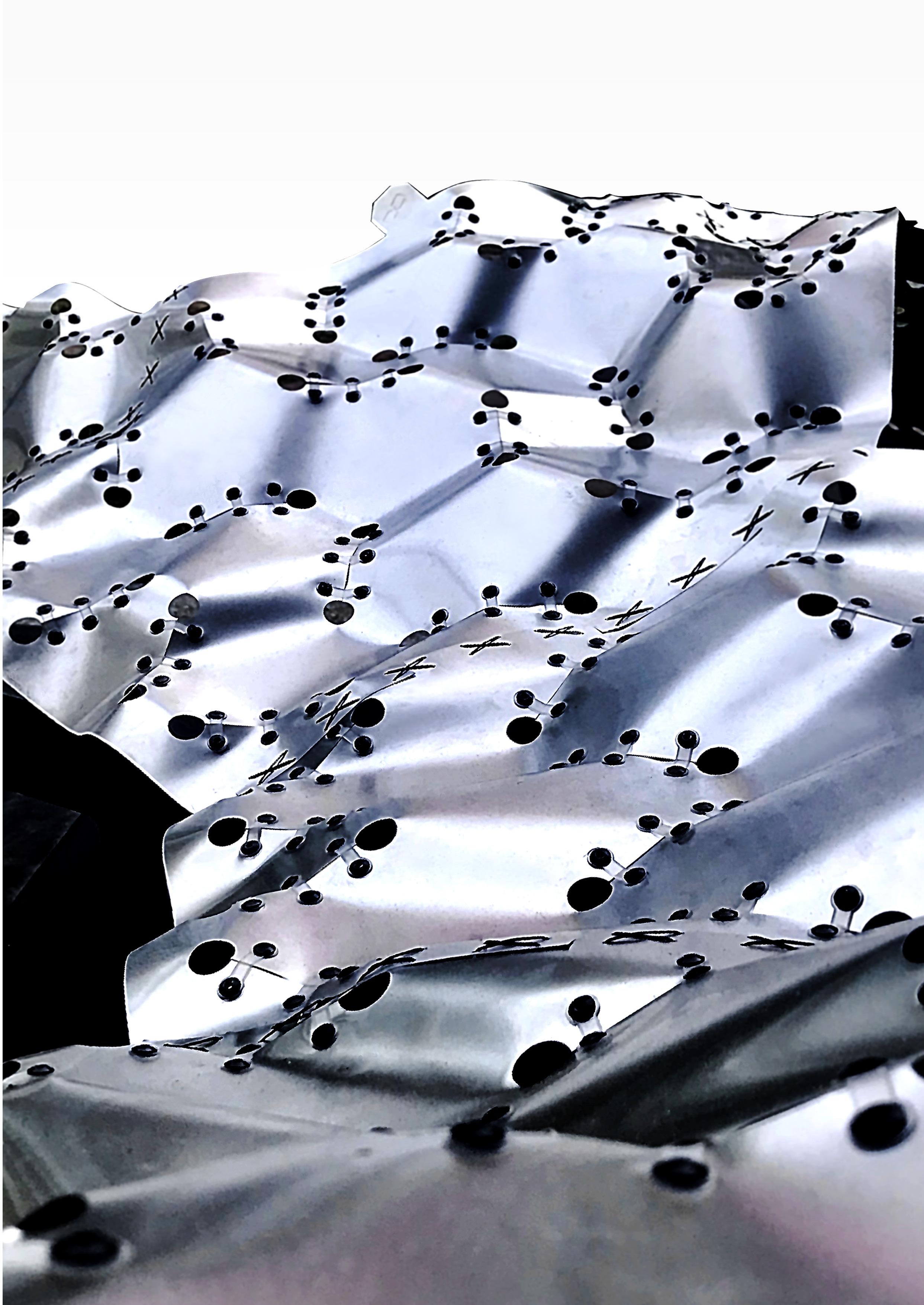 Fig.1-02
Regardingtheworkflow,theresearch introducedanewbending-activedesign strategythatintegratesthecharacteristics ofform-finding(bottom-up)andformconversion(top-down)techniques
Startingwiththesampleddata,abending simulationofpattern-basedopeningswas usedtopredictthechangeinoverallplate bending.
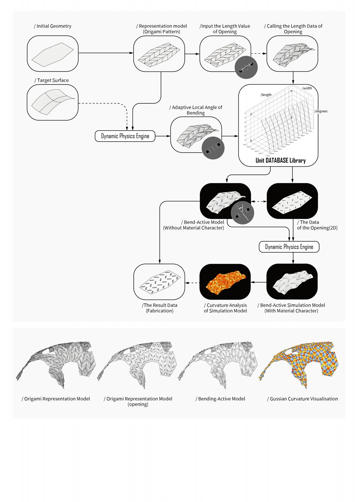
Toconverttheopeningandthebending angle,weestablishedthemathematical functionlibrarybybendingtestingthe resultoflinearregression.Therefore,the openingvaluesandthebendingangles couldbebi-directionaltransferredthrough thisfunctionlibrary.
While the Miura folding is adapting to the purpose surface, the elasticity of the model had been extracted and the representation of the folding model could remain the rigid crease. Then, we could get the value of each local folding angle, which could be used to transfer into the opening through the function library. Following this, we add a new vertex on each mesh face and contribute the new relationship with each initial
mesh vertex to create a new mesh edge and mesh face. After that, we must add the proper pairs of vertices on the opening edge again to set up the coincidence of opening in the dynamic physical simulation. In the last stage, we subdivided the mesh into proper densities and add the elasticity back to the model to simulate the sewing opening.
Fig.1-03 Workflow of pattern-based strategy in bending-active systemTo efficiently convert the folding representation into the bending-active model, we adopt linear regression to build the math function to represent the data library. This data library consists of three parameters, such as opening length, width, and deformation angle. First of all, we set up a pair of patterns to simulate the deformation and extract the endpoints to build the folding representation for measuring the folding angle.
Starting with the fixed opening length of 60mm and the width stepped increased by 1mm from 0mm to 50mm. Moreover, we use linear regression to convert these data into a math linear function with two variables. Next, based on using this method, the length gradually stepped increased by 10mm from 70mm to 160mm and created a three-dimension math function created by this series of linear functions.
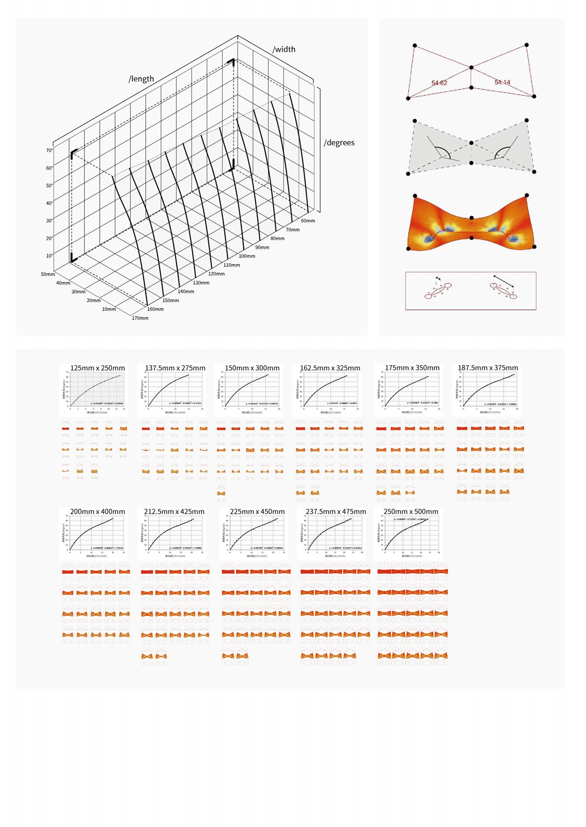 Fig.1-05 Transformation function library
Fig.1-06 Method of angle measuring
Fig.1-05 Transformation function library
Fig.1-06 Method of angle measuring
Thetypicalsurfacemock-upsrevealtheperformanceof thestrategy.First,whileperformingthearcsurface,the peakangle,andwidthvalueofthebendingdeformation werelargethanthevalleyvalue.Moreover,eachpair opening,perpendiculartothebendingdirection, showsthesamevalue.Then,whileperformingthe twistbehaviour,thepairsofpeakandvalleyvalueshad oppositerelationships.Third,thesaddlebehaviour demonstratesthetrendsofperformingthetypicalarc intheparalleldirection.Furthermore,thevaluesof boththepeakandvalleyhavedecreasedtrendsfrom thecentreoutwardintheperpendiculardirection.
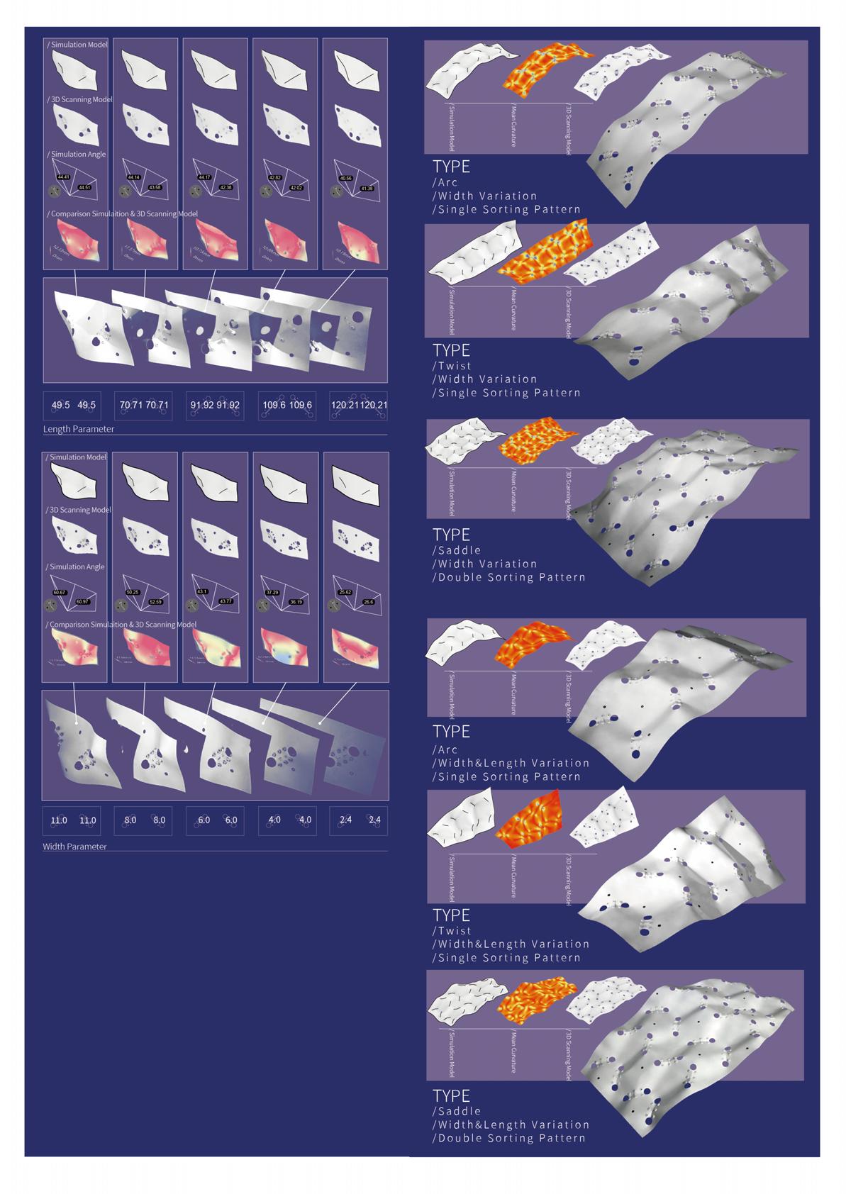
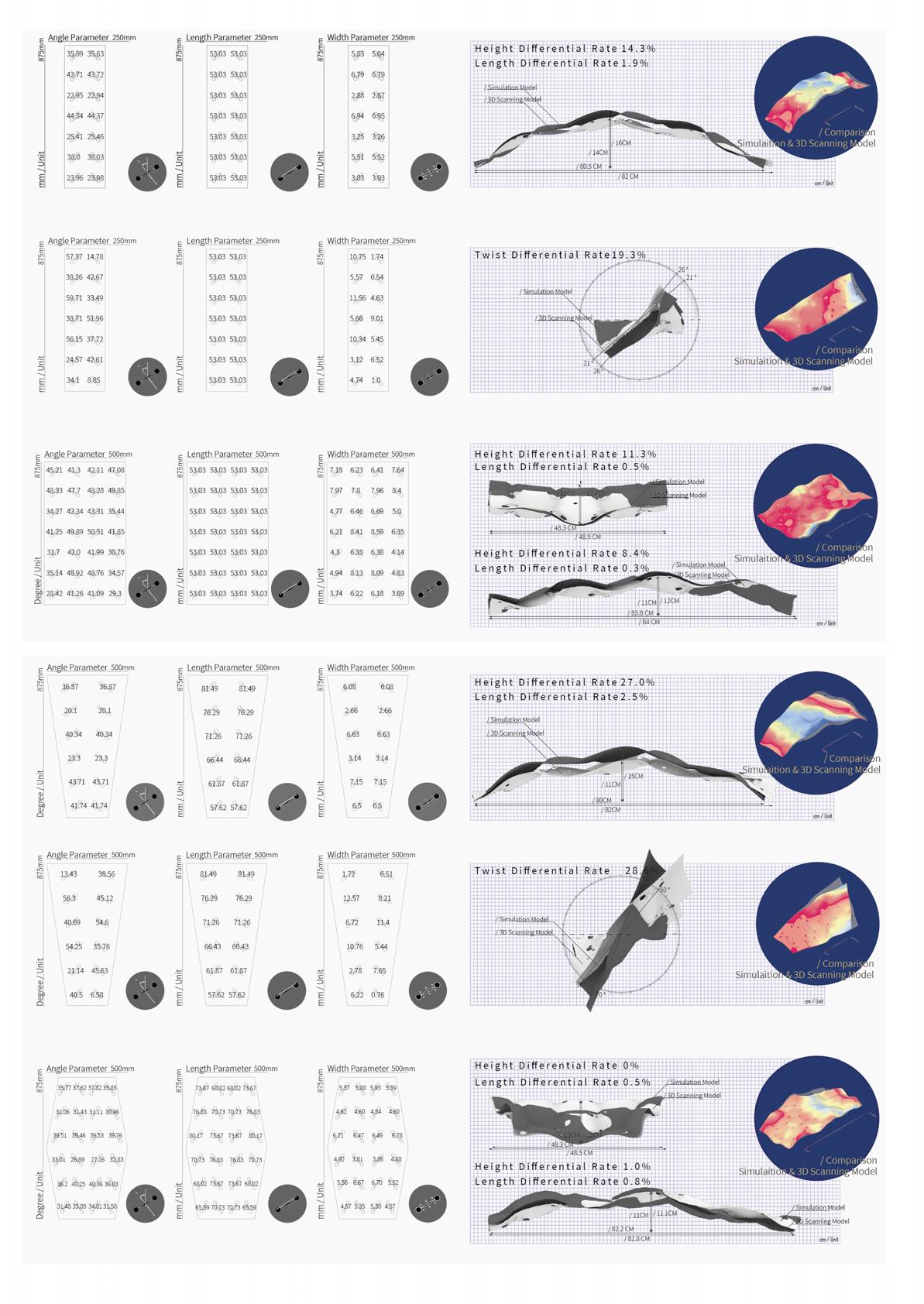 Fig.1-09 The parameter of typical surface (fixed length)
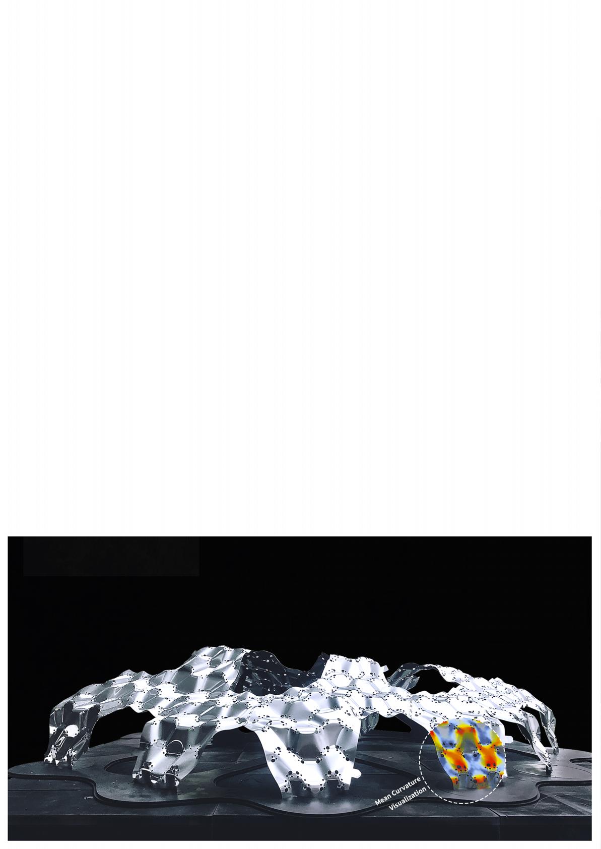
First of all, we installed a spatial installation (3.3m * 2.6m * 0.7m) utilising the bending active method of the panel assembly, and the geometry of this installation demonstrates the performance of arc, twist, and saddle
Furthermore, in comparison to the more common surface deformation methods, the strategy of our research only required cut patterns to control the surface curvature as well as control the border of the panels by the designer to greatly reduce material waste, instead of the typical form conversion strategy generates the unpredictable border of panels.
While assembling the panels, three pairs of holes were located at the extension of the fixed distance from the border of each opening and locked with the fixed-size plastic band and the rivet.
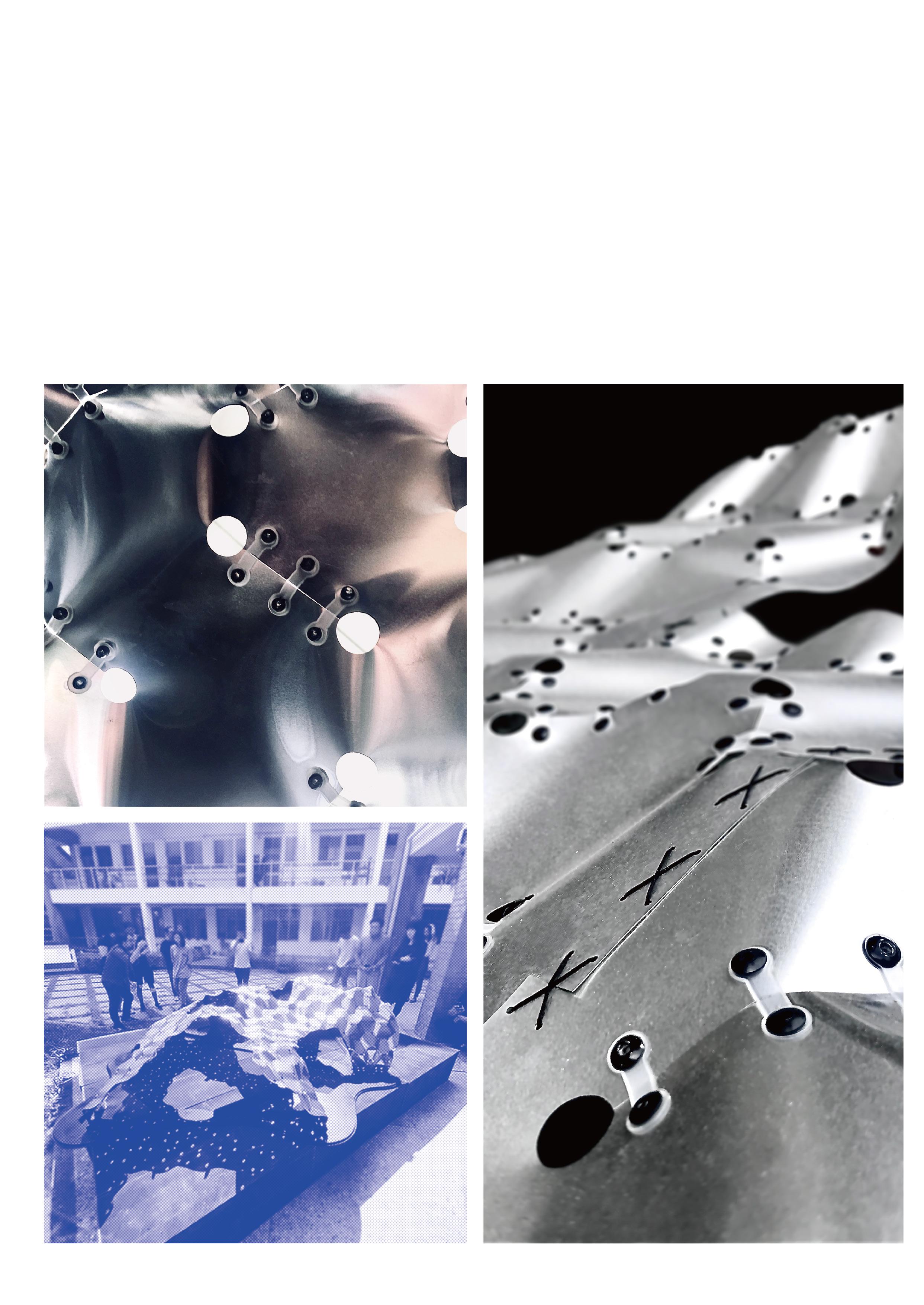 Fig.1-11 The detail of opening sewing
Fig.1-12 Final prototype
Fig.1-11 The detail of opening sewing
Fig.1-12 Final prototype
Due to the maintenance of panel elasticity, 16 panels (90cm * 60cm each) rely on a bag (60cm * 35cm * 35cm) hung in a motorcycle (see figure 5) and merely required one-hundredth of capacity to transport the materials. Moreover, the whole process of assembling merely spend three days with two workers.
This result shows the bending-active plate system of this research allows for convenient transportation and repeatable assembly as well. Accordingly, the advantages are suitable for architectural applications requiring high degrees of flexibility and lightweight construction.
 Fig.1-14 The process of panel sewing
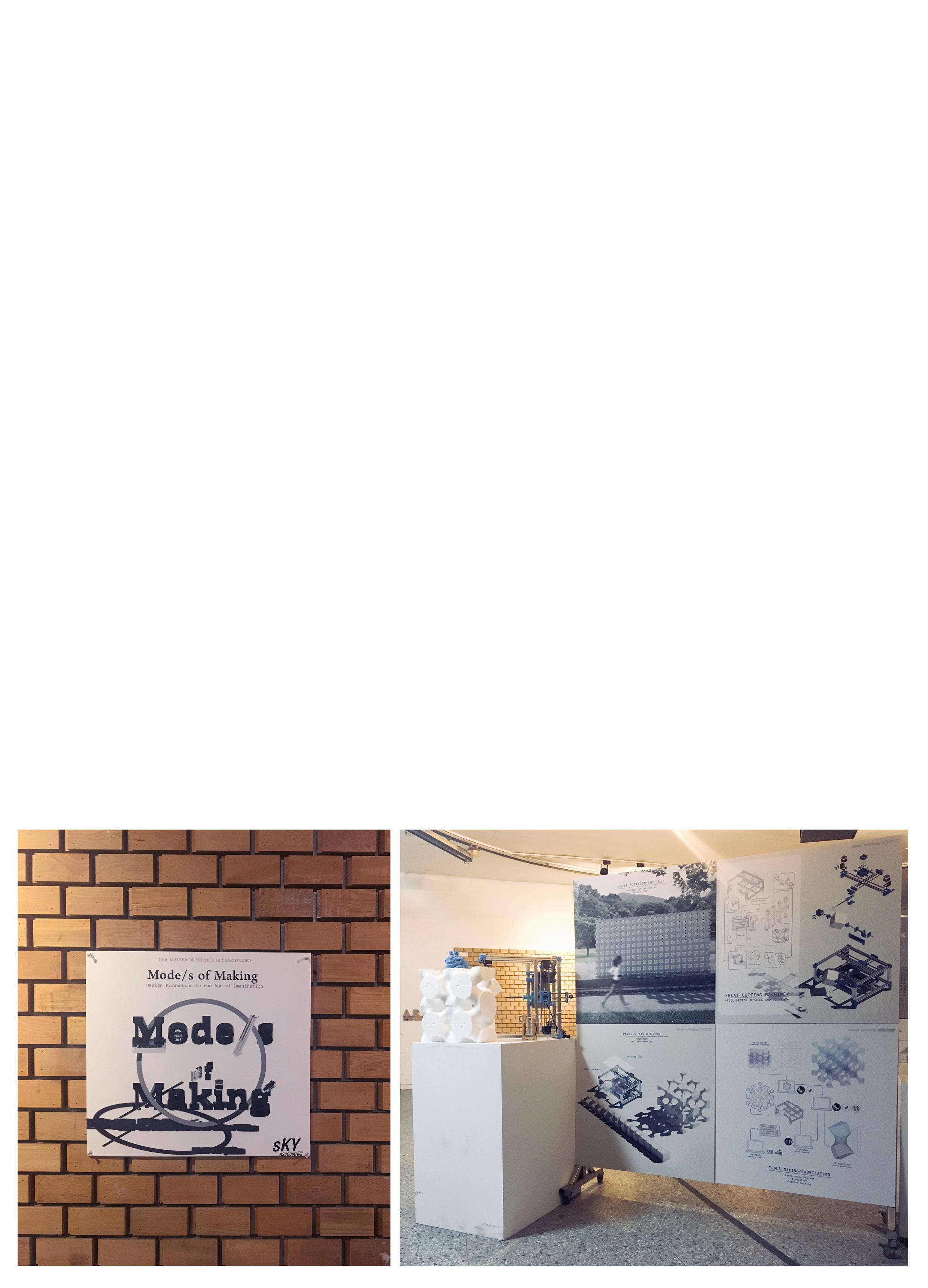
MODE/S OF MAKING Heat Rotate Cutting
Keywords: Mass Customization, Digital Craftsmanship, Digital Fabrication, Computational Simulation
Description: Studio Project
Tutors: Prof. Kane Yanagawa
Location: Tainan, Taiwan
Institution: National Cheng Kung University
Date: 2018
Collaboration: Jan Kyselý(Photo)
Over the past 2.5 million years, humanity has continued to advance new tools at an ever-accelerating rate from the abacus, to the slide rule, calculator, and computer. Although these innovations are typically made to address specific problems, each new tool correspondingly opens doors to numerous unforeseen opportunities.
The project explores the use of machines as the designer's design tool, using open source frame Arduino as well as Marlin to integrate the design and fabrication. Moreover, the designer started from the study of the fabrication mechanism and respond to the design process, using Arduino to control the cutting path, speed, and other variables.
In sum, the research uses emergent digital technologies to bridge the gap between designers and manufacturing which coincidently brings interesting results.

The material system adopts polystyrene bricks as the main material and heat rotation cuts to every single brick to practice mass customization. To directly fabricate the customized bricks, we build a mass-customized frame with data format transformation and machine-customized fabrication. Overall, it can be seen that the procedure from design to fabrication consists of five stages. The process has five stages,
beginning with geometry development. Then it will undergo the cutting path optimization and the data format be converted into Gcode, which is used to read by the machine. Meanwhile, the machine set by Arduino was remodelled from a 3D printer open-source frame- Marlin. Finally, ends up with the assembly process through referencing the simulation model.
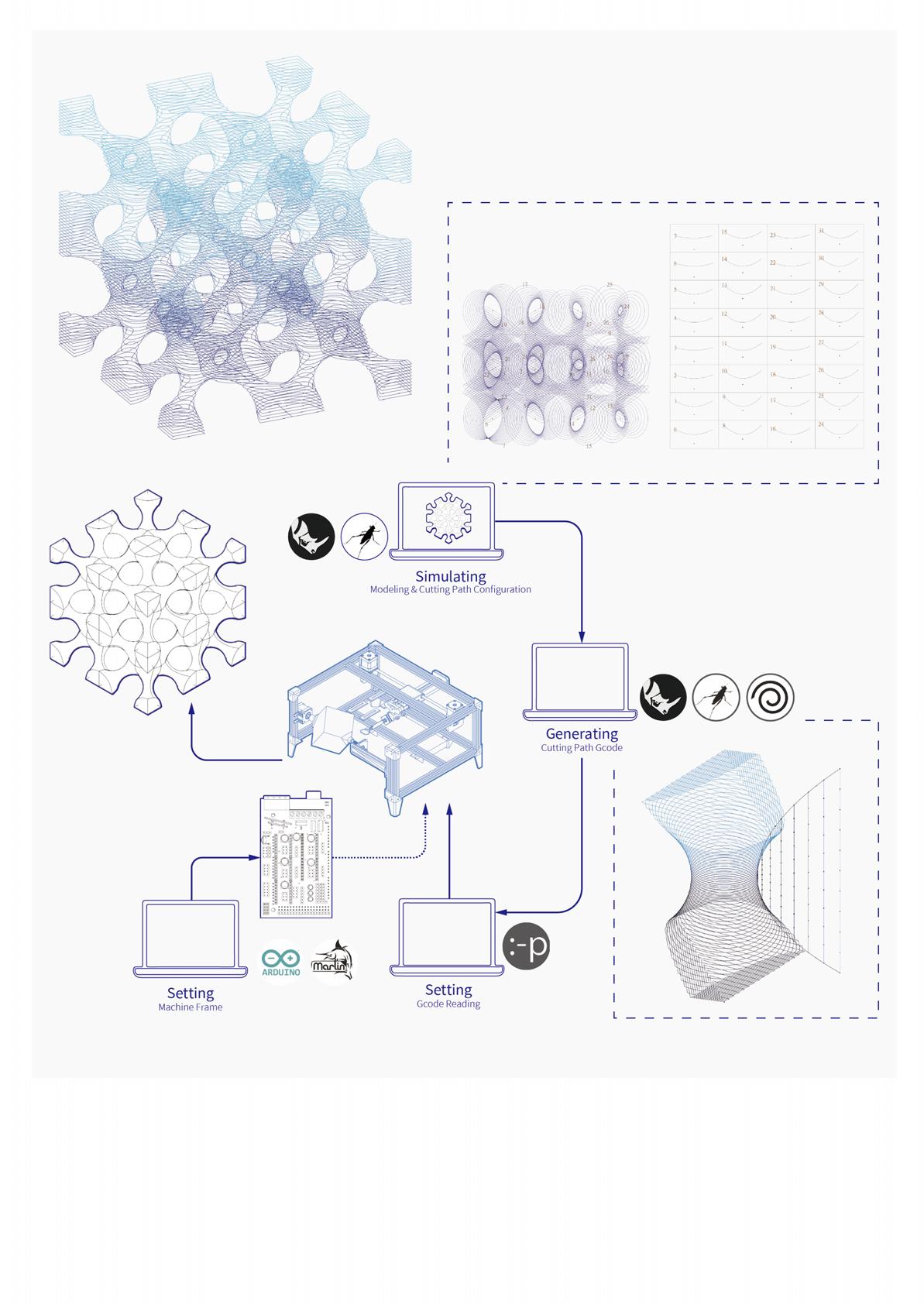
The hardware system was built with aluminium and the customized units were built with 3D printing. The machine was designed by the core XY system and was controlled by two stepper motors. When stepper motors have the same direction, the motion of the mechanism has a vertical direction. On the contrary, when stepper motors have the opposite direction, the motion of the mechanism has a horizontal direction.
Next, the rotation mechanism relies on a stepper motor controlling the speed and direction of rotation. The opposite has a holder, which is adaptive to hold various sizes of material. Lastly, the Endstop was used to adjust the cutting position.

Thevariouscircularsurfacebrickswerefabricatedbyrotating cuttingpaths.Eachcustombrickwasdesignedtoconnect withotherssmoothlyandtaggedwiththelocationnumber. Moreover,singlebricksspentabout10-15minutesfor fabricating.Whileassemblingthebricks,8brickunitscanbe assembledintobiggerunitsandsoon,whichcontributetothe skeletonpatternswithdifferentsizesofinternalsanddensities.
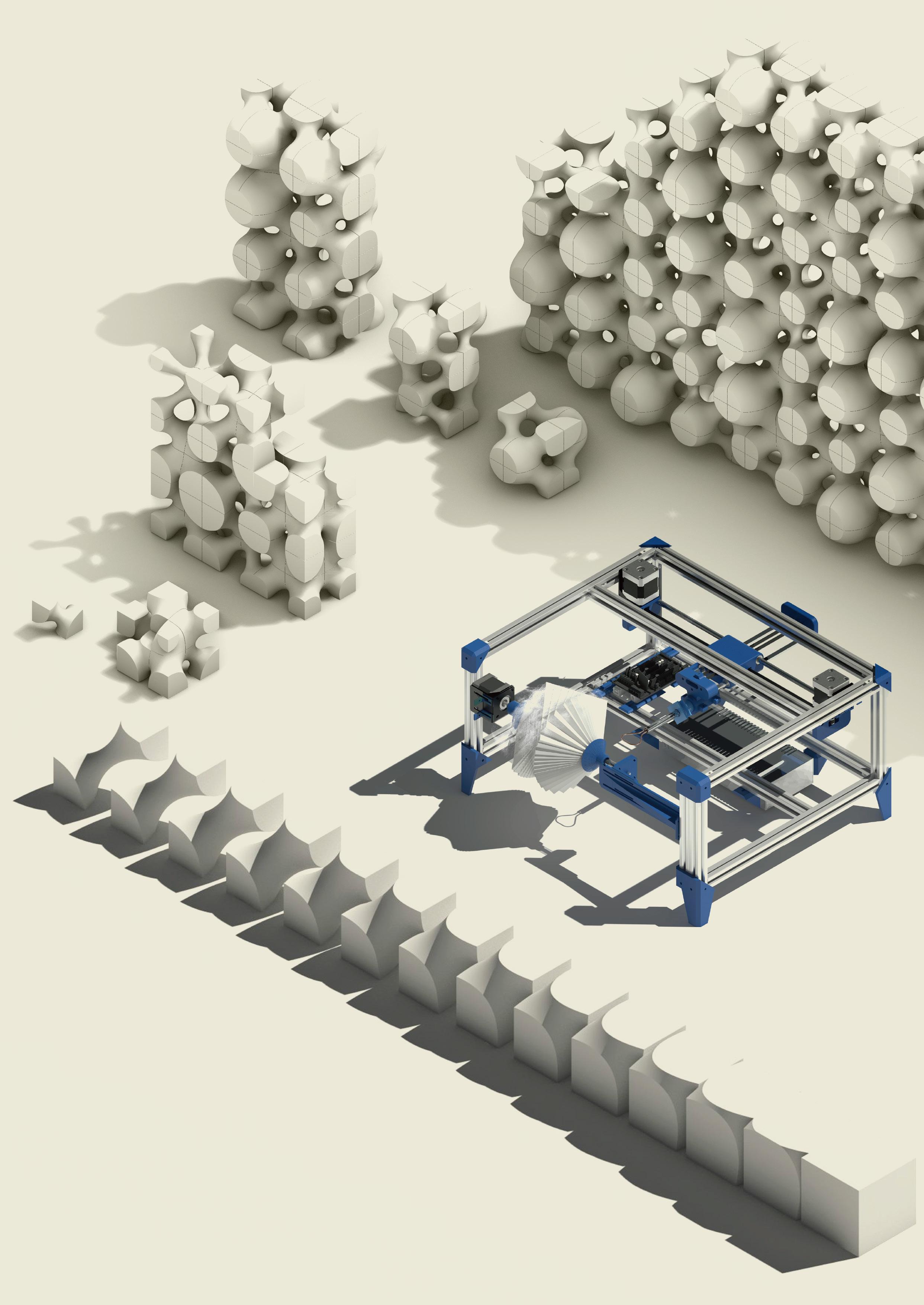
Themachinehastwomainmechanismssystem, therotatingmovementsystem(Y)andtheplane movementsystem(XZ).Theplanemovementsystem controlsthetoolpathofthesection,andtherotating movementsystemcontrolsthesectionposition.

/01stepmotor
/02motorholder
/03smoothmetalrods
/04belt
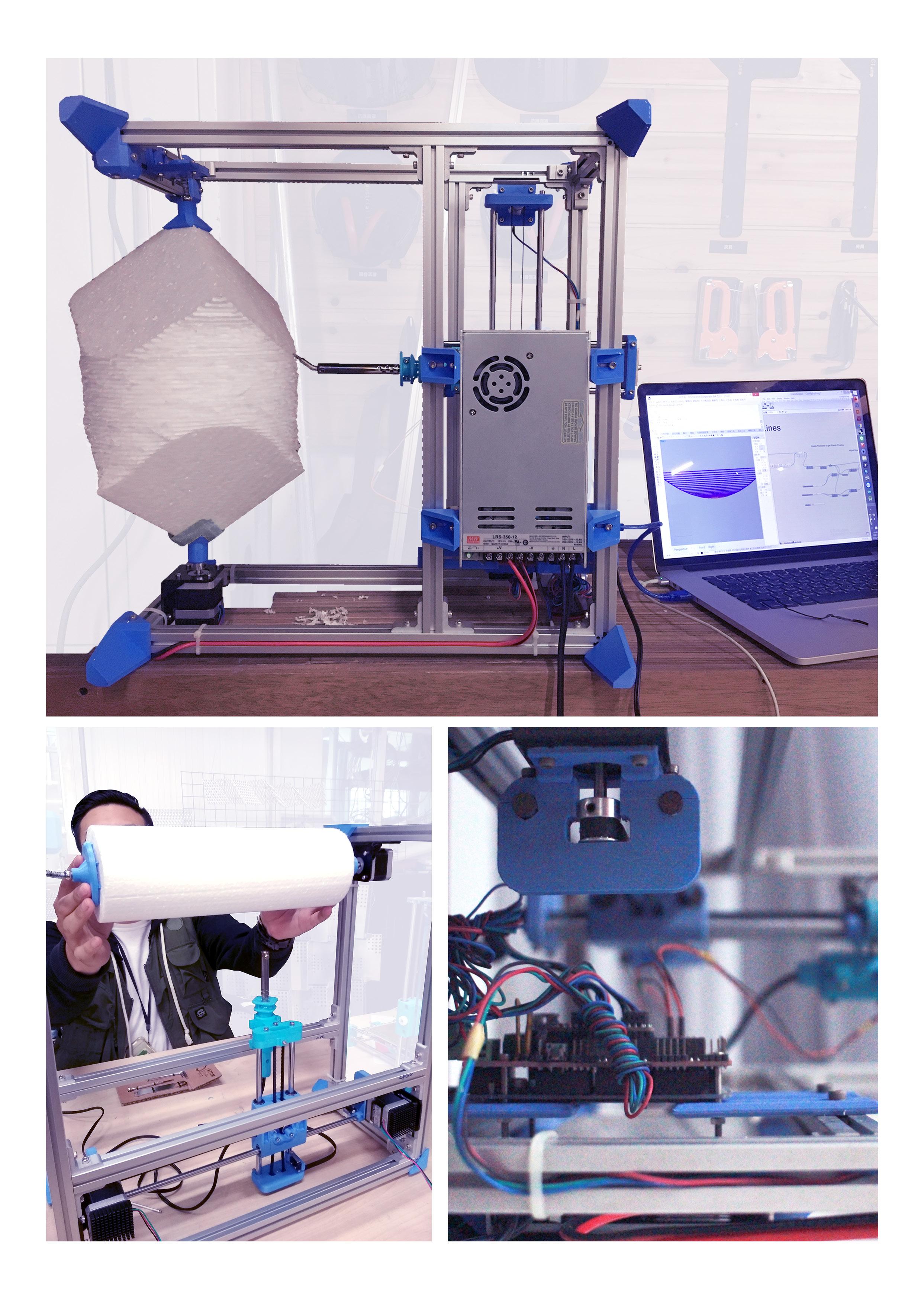 Fig.2-06 Fabricating process
Fig.2-07 Fabricating process
Photo by Jan Kyselý
Fig.2-06 Fabricating process
Fig.2-07 Fabricating process
Photo by Jan Kyselý
The fabrication process consists of two main steps, roughing and milling. At this point, the prototype aimed to integrate the potential of rotated cutting, the polystyrene blocks were cut by the different depths of the path and arranged to assemble in a specific position. While the roughing period, each tool path was parallel and have a higher forward-moving of depth to decrease the fabricating time consumption. Then, the milling period was one slower movement with a continuous path to make sure the final face is smooth.
Instead of general design to fabricate workflow, studying and inspiring from the fabricating tool have a high potential to bring serendipity. At the first, the design expected to cut the form such as the skeleton pattern and control the gap variety with the round thickness of the skeleton. After the roughing step and removing the most of material, the machine started to mill according to the tool path and accidentally revealed the unique pattern generated from the tool path.
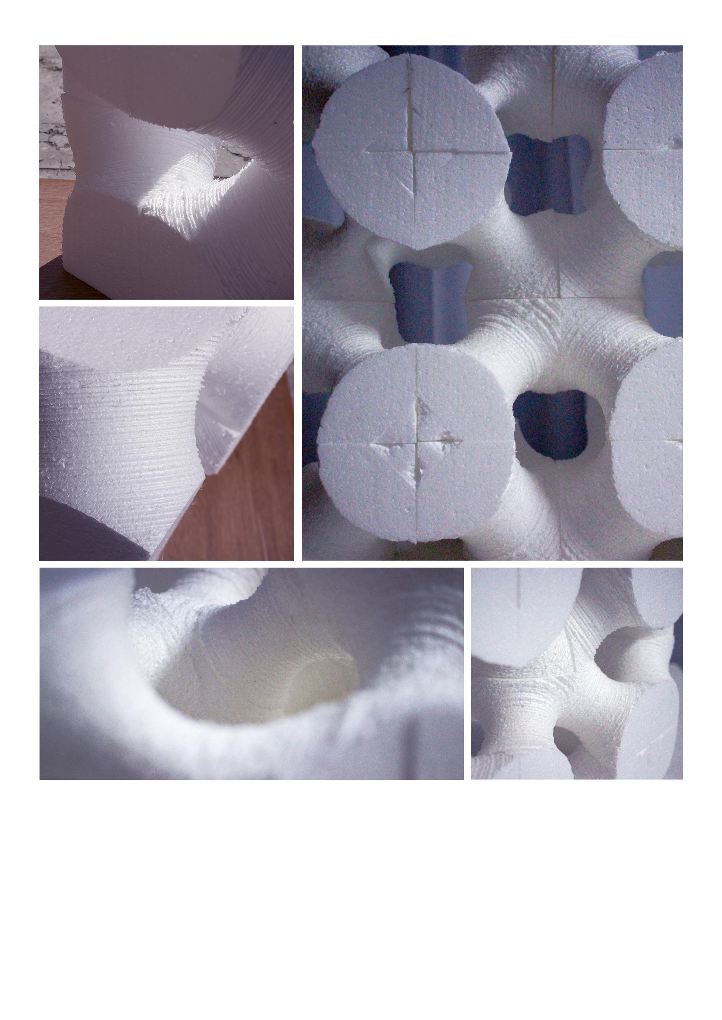 Fig.2-12 Real model prototype
Fig.2-13 Real model prototype
Fig.2-09 Real model prototype
Photo by Jan Kyselý
Fig.2-10 Real model prototype
Photo by Jan Kyselý
Fig.2-11 Real model prototype
Fig.2-12 Real model prototype
Fig.2-13 Real model prototype
Fig.2-09 Real model prototype
Photo by Jan Kyselý
Fig.2-10 Real model prototype
Photo by Jan Kyselý
Fig.2-11 Real model prototype
ENTRANCE INSTALLATION ART
Taichung Nan Shan no.6 Square
Keywords: Mass Customization, Fabrication Drawings, Complex Modelling, Computational Simulation
Description: Work Project
Employer: Peter Chen
Location: Taichung, Taiwan
Institution: PKD Engineering Consultants
Date: 2021
Collaboration: Zhi-Yu Guo(2D Sector), Monita(Structural Sector)
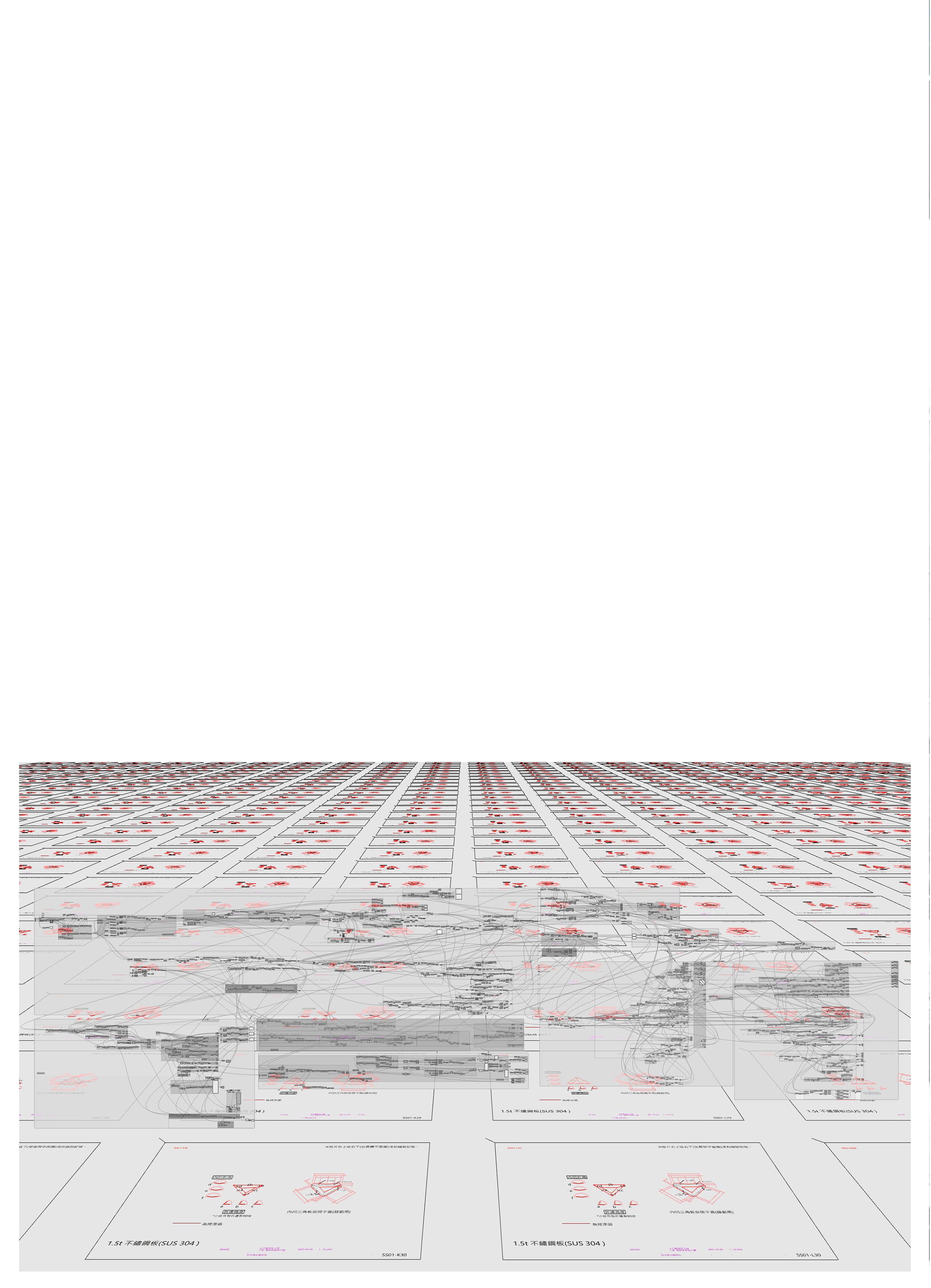
The entrance installation art project of the Taichung Nan Shan no.6 square is entrusted by Fu Tsu Construction and is a public art of the master building. The project was developed by three people team for three months and is currently on exhibit. This chapter records the parts of scheme development, 3D modelling and fabricating drawings, in which I played a key role in the project.
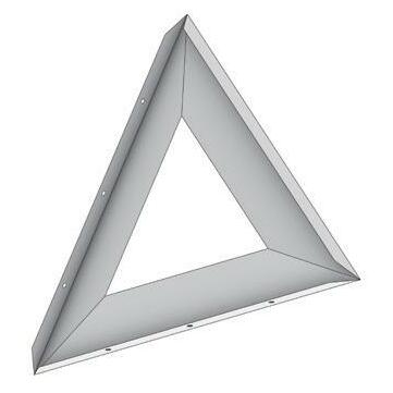
The installation was assembled with 600 aluminium folding panels with various openings, which were fabricated by a traditional aluminium factory. The assembly process is merely by human hands. In sum, the key point of this project is the bi-directional transformation of 3D models and 2D drawings and delivering the drawing to hand fabricating.
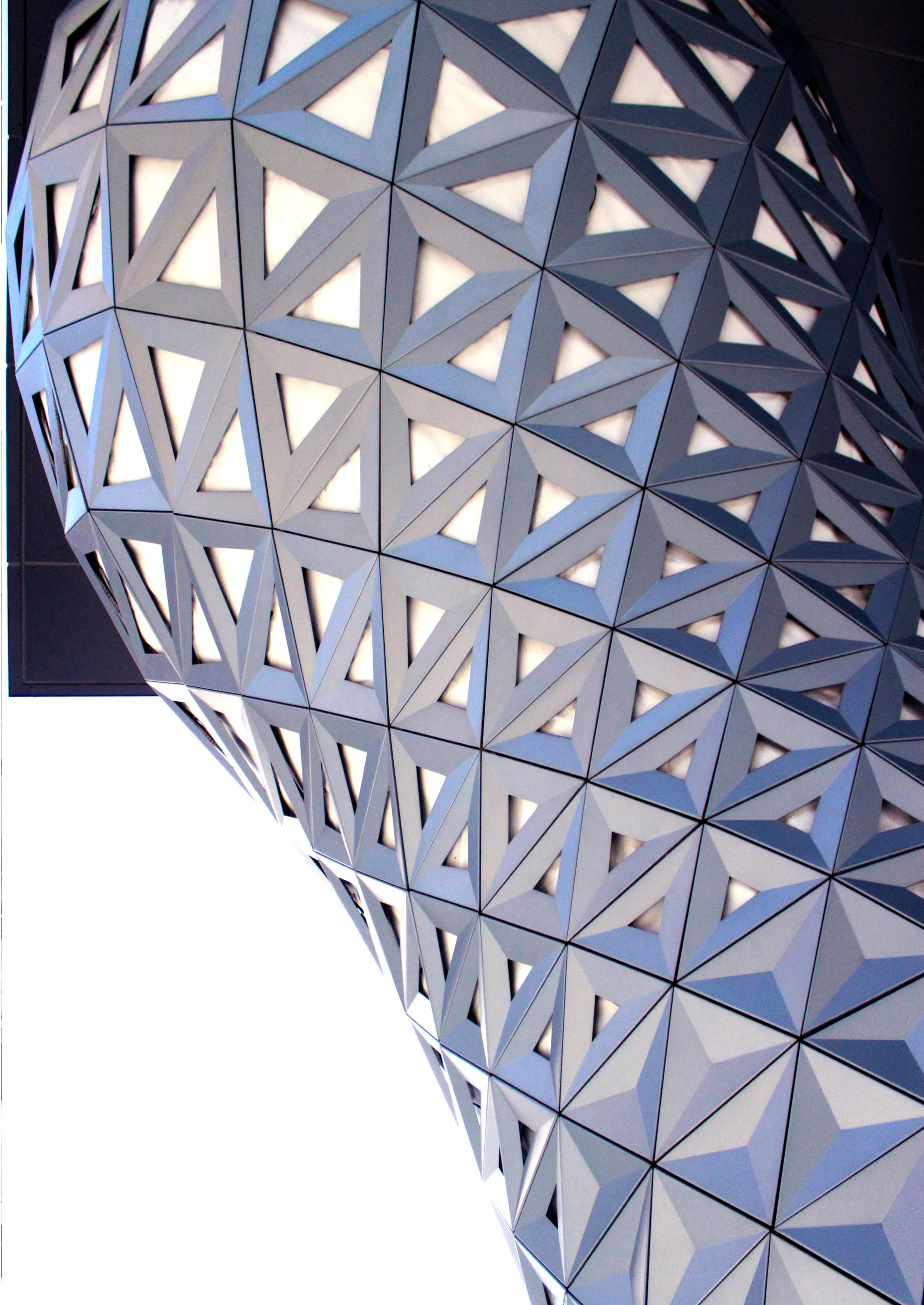 Fig.3-01
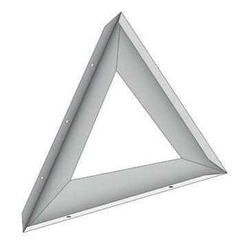
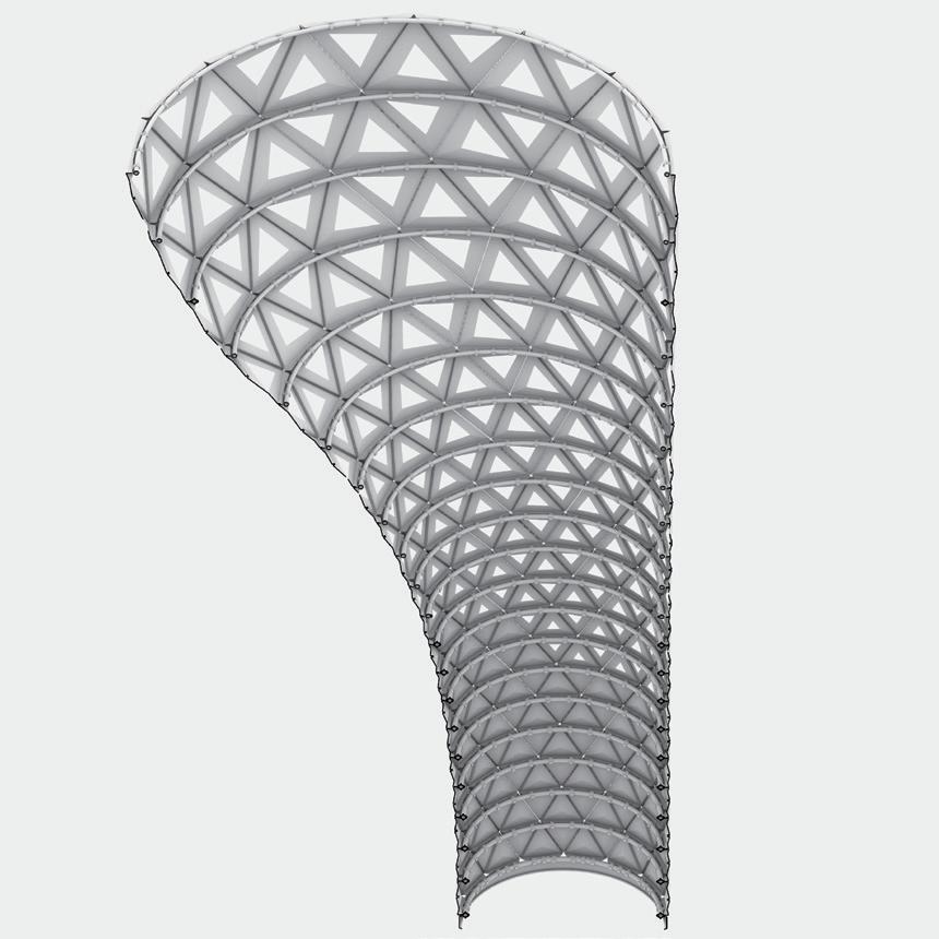
The geometry of the installation art started with a simple NURBS surface. Then, subdividing the triangle size depends on considering the manufacturing limitation such as the fabricating scope. Following this, adding the depth from the control of the triangle panel in order to create the pattern. The last, using the helix curve to evaluate the distance with every central point of the panels and making the openings on every panel with the list of distances.

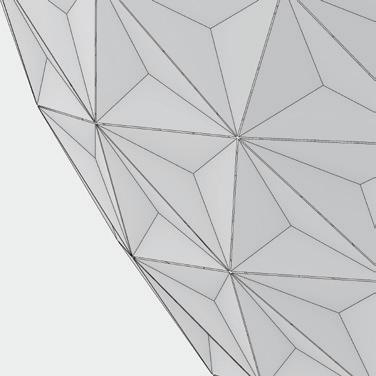
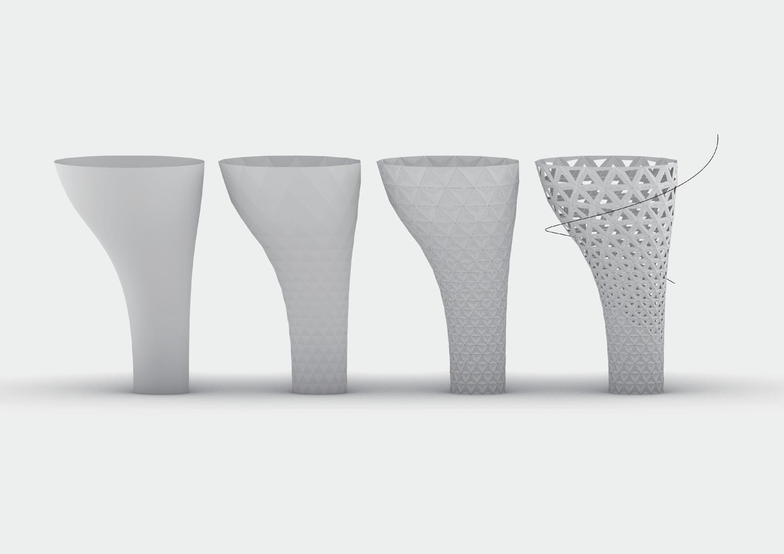
While developing the pattern of the panels, we provided various schemes to the client. In terms of the size of the opening on the panels, the minimum radius of the triangle inscribed circle is large than 8cm in order to provide enough space for repairing the light facility. Regarding the minimum height of the opening panel, it is necessary to be higher than 200 meters to make sure the security of the children. In sum, all of the pattern schemes are satisfied the above requirements.
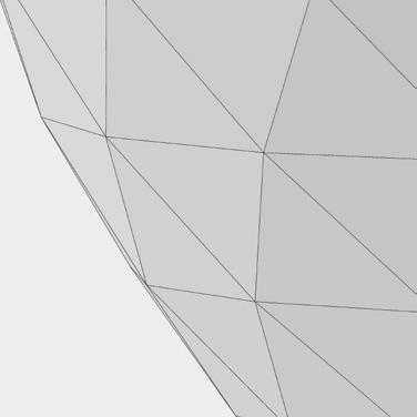
 Fig.3-02 The pattern development
Fig.3-03 The schemes of pattern
Fig.3-02 The pattern development
Fig.3-02 The pattern development
Fig.3-03 The schemes of pattern
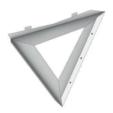
The assembly system has two types, including two ears panels and three ears panels. The panels were hung by the module hanger. Moreover, every ear of the folding panel has a customized shape to cooperate with the fixed depth of the component. Every two panels were a pair with fixed holes in the middle and the upper ear and lower ear of each panel had pairs of alignment holes.


In order to deliver the fabricating drawings to the local traditional factory, we integrate each folding angle and every manual checking data into the drawings. Meanwhile, depends on laser cutting, to transform the digital data into real folding panels. All in all, the construction could rely on the machine fabricating and the checking data to make sure every panel is successfully fabricated.
FR515. Hex Bolts (M5 x 15mm)
FR520. Hex Bolts (M5 x 20mm)
FR615. Hex Bolts (M6 x 15mm)
FK510. Round Head Machine Screw (M5 x 10mm)
FG4813. Round Head Self-Drill Screw (M4.8 x 13mm)
FG4819. Round Head Self-Drill Screw (M4.8 x 19mm)
ST02. Steel Plate (2mm)
-Hot Dipped Galvanized
ST05. Steel Plate (5mm)
-Hot Dipped Galvanized
ST09. Steel Plate (9mm)
-Hot Dipped Galvanized
ST12. Steel Plate (12mm)
-Hot Dipped Galvanized
ST5050. Steel Square Tube (50 x 50 x 3t)
-Hot Dipped Galvanized
ST1032. Steel Square Tube (100 x 100 x 3.2t)
-Hot Dipped Galvanized
ST1045. Steel Square Tube (100 x 100 x 4.5t)
-Hot Dipped Galvanized
ST106. Steel Square Tube (100 x 100 x 6t)
-Hot Dipped Galvanized
SS753. Steel Folded Plate (75 x 75 x 3t)
SS7545. Steel Folded Plate (75 x 75 x 4.5t)
SS01. Stainless Steel Plate (1.5mm)
SS381. Stainless Steel Pipe (1.5” 3mm)
EX01. Alloy 6105-T5 (L=30mm)
L01. LED Strip (L=100~500mm)
L02. LED Strip Aluminum Channel Holder (L=15mm)
(assembly on site) (assembly on site) (assembly on site) (assembly on site) (assembly on site) (assembly on site) bracing (assembly on site) (assembly on site) Fig.3-12 Module C of steel structure - perspective Fig.3-11 Module B of steel structure - perspective(drilling Ø6.5) plug weld (two screws for length < 500mm; three screws for length > 500mm)
oval slot Ø6.5 x 10
(reference only)
reference only
reference only
(drilling Ø6.5) plug weld (two screws for length < 500mm; three screws for length > 500mm)
oval slot Ø6.5 x 10
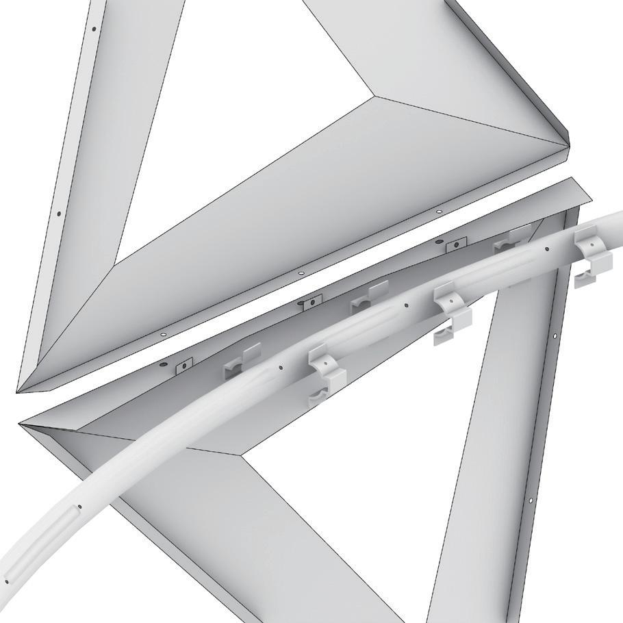
Overall, there are three layers of systems including the panel system, the steel pipes system, and the structure system. The steel pipes system was used to locate the panels; each pipe had a different radius. Moreover, the pipes were accurately located by the beam and column system which was built with steel tubes. Since module A had a large radius of the pipe system and the panel system, the steel tube system add the bracings to satisfy the structure needed.
Regarding the reference standard, it is necessary to establish a fixed reference surface. In the detailed drawing, we can see every component was located referencing the central curve of the pipe. Furthermore, every central curve of the pipe was generated from the intersection of a reference surface and the height of the pipes in order to efficiently located the various module components which have complicated relationships with the reference surface.
(EX01 drilling Ø4.5, SS01 drilling Ø5.5) (EX01 drilling Ø4.5, SS01 drilling Ø5.5) (EX01 drilling Ø4.5, SS01 drilling Ø4) (EX01 drilling Ø4.5, SS01 drilling Ø4) central curve of the pipe central curve of the pipe (EX01 drilling Ø5.5) (EX01 drilling Ø5.5)The installation art was almost 8 meters in height and was located near the Taichung city train station, a high-frequency traffic commercial district. Following this point, photos reveal how to divide the installation into three modules and fabricate them. Every module was no need for scaffolding to aid fabricating. The modules were preassembly and pre-sprayed in the factory before transporting them to the real site in order to decrease the time consumption of assembly on the real site and satisfy the transporting size of the truck and the width of the roads.
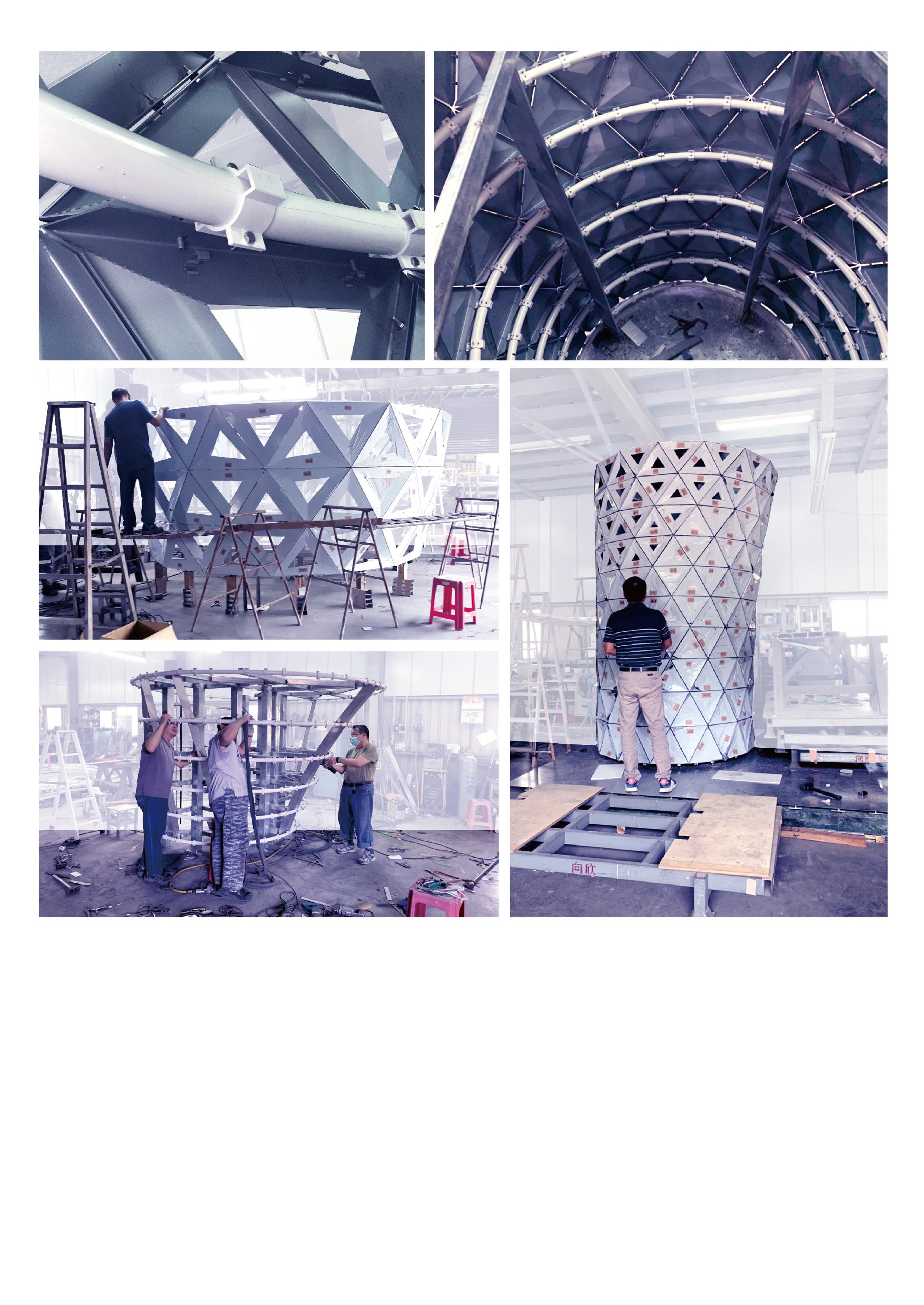 Fig.3-15 The photo of detail
Fig.3-16 The photo of structure (inside)
Fig.3-17 The photo of module A
Fig.3-18 The photo of module B
Fig.3-19 The photo of module C
Fig.3-15 The photo of detail
Fig.3-16 The photo of structure (inside)
Fig.3-17 The photo of module A
Fig.3-18 The photo of module B
Fig.3-19 The photo of module C
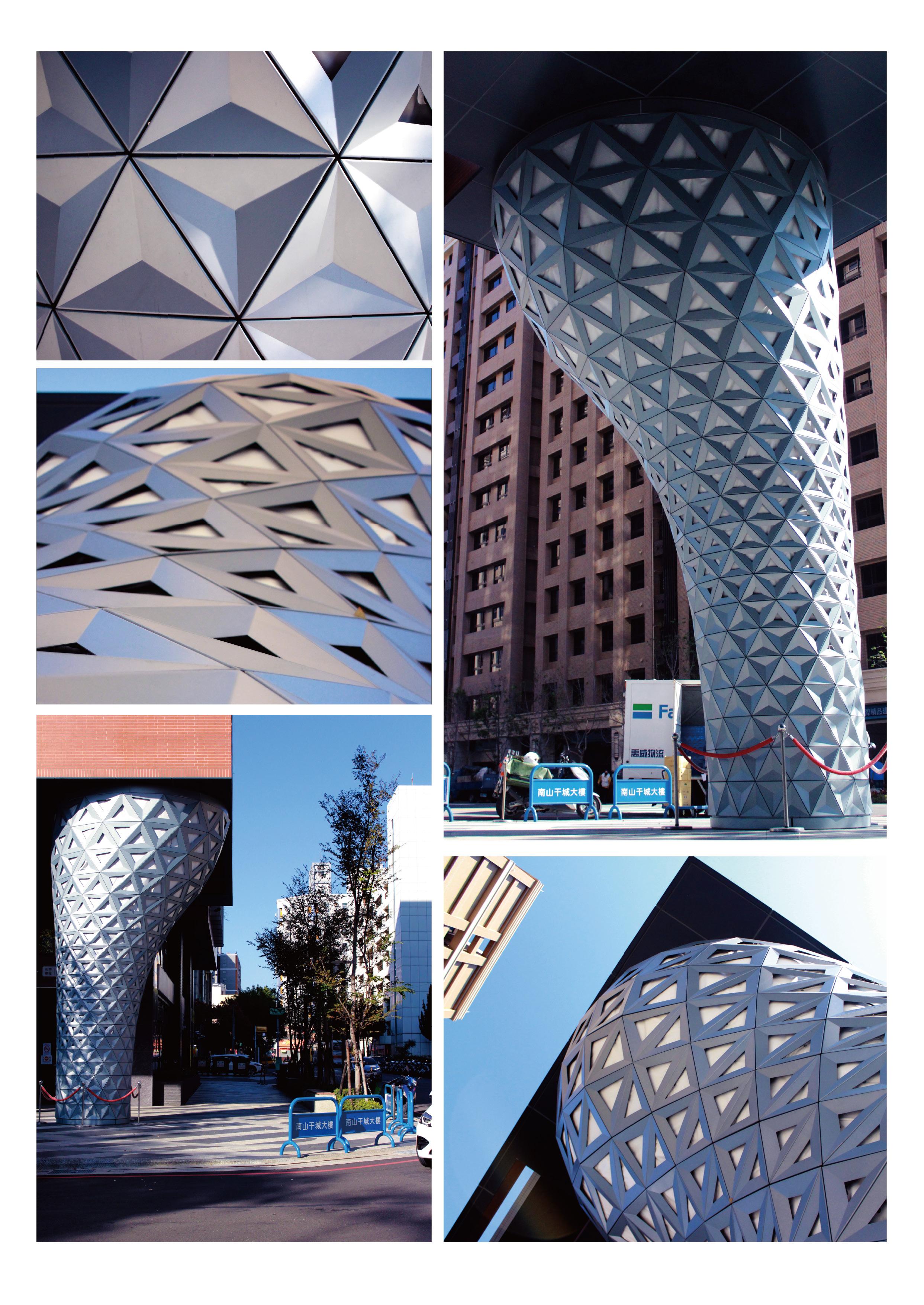 Fig.3-20 The photo of panel detail
Fig.3-21 The photo of panel detail
Fig.3-23 The photo in real site
Fig.3-24 The photo in real site
Fig.3-20 The photo of panel detail
Fig.3-21 The photo of panel detail
Fig.3-23 The photo in real site
Fig.3-24 The photo in real site
INSIDE OUT IDF 2019 Workshop
Keywords: Minimal Surface, Form Finding, Weighted-Mesh, Differential Tiling
Description: Workshop
Tutors: Prof. Chung-Han, Lee
Location: Yunlin, Taiwan
Institution: Idea Factory, National Yunlin University of Science and Technology
Date: 2019
Collaboration: Individual work Kenta Saito(Cooperation Prototype Assembly) Group work IDF2019 Workshop
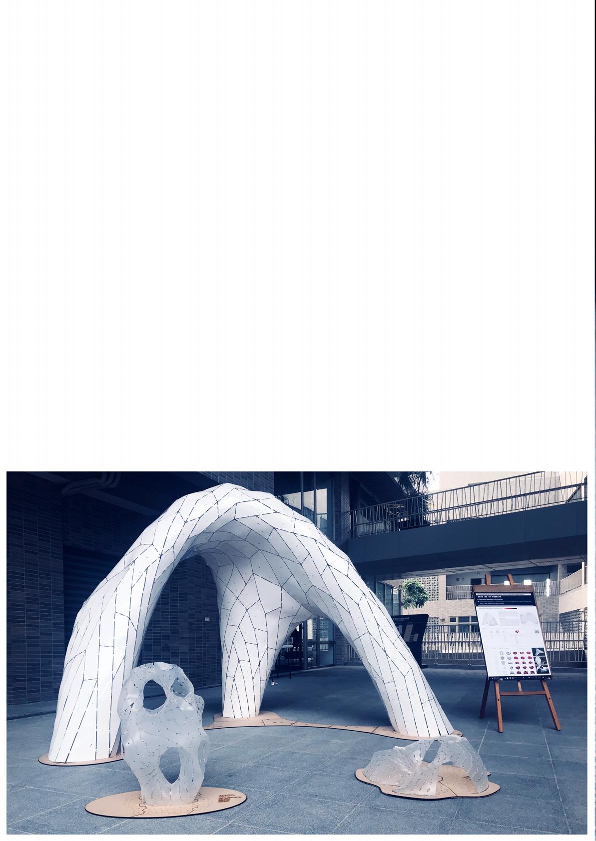
Inside Out is a workshop individual result of the IDF 2019 workshop. This 5-days workshop focused on the use of differential tiling on complex geometry. Moreover, the workshop explored both the techniques for the design and the behind theories of mesh analysis methods.
The workshop covered instruction in Grasshopper, Kangaroo and Ivy to introduce the design workflow of the mesh. In addition, the workshop has two phases, two days for two people teamwork and three days for whole group work. The chapter extracted the small teamwork result that I was responsible for and demonstrated the process of the final prototype.
Fig.4-01 Final Results of the Workshop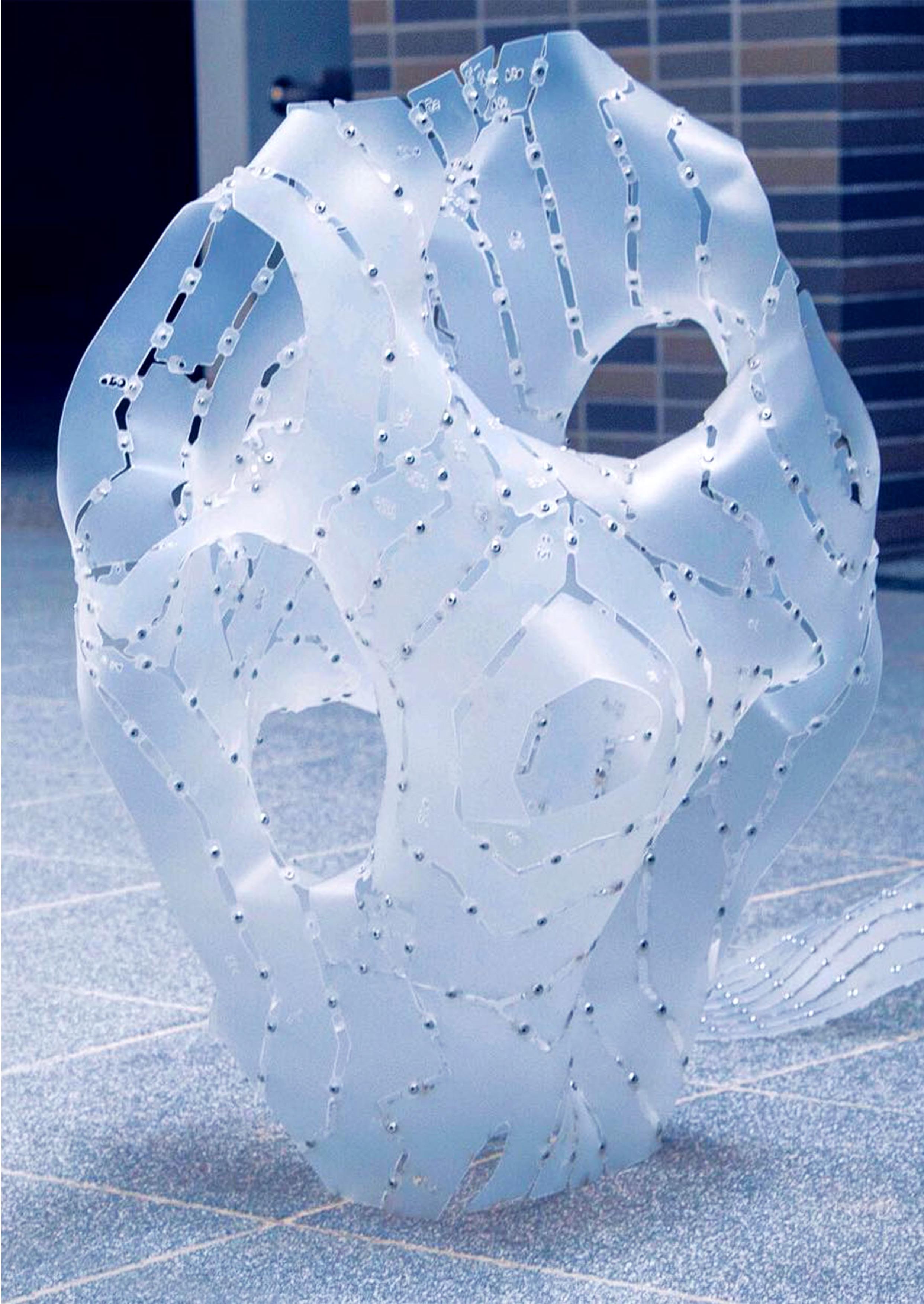 Fig.4-02
Physical Model
Fig.4-02
Physical Model
First of all, the initial geometry is a mathematical geometry called the Split P Surface. Then, the longest border of the geometry was selected to limit movable on the plane while the Form-Finding phase. Meanwhile, every mesh edge was configured to grow 1.2 times in length and used the laplacian smooth method to smooth the mesh.
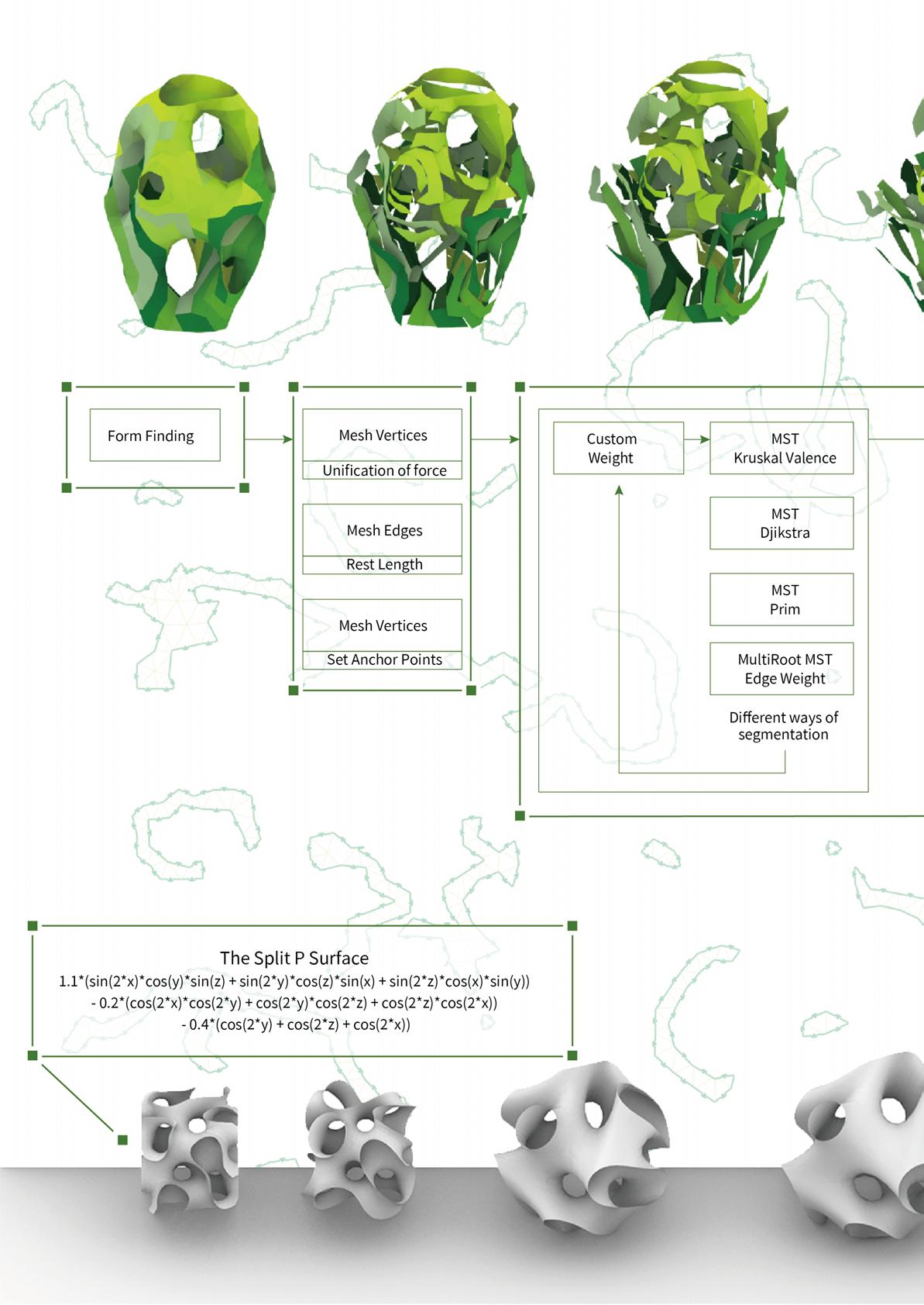
In terms of the differential complex geometry mesh, we use different algorithms and add some custom weight in order to make the segmentation following the targets, the minimum number of panels and the lowest curvature changes on each panel. Moreover, it is necessary to insure each segmentation is smaller than the size of the laser cut machine.
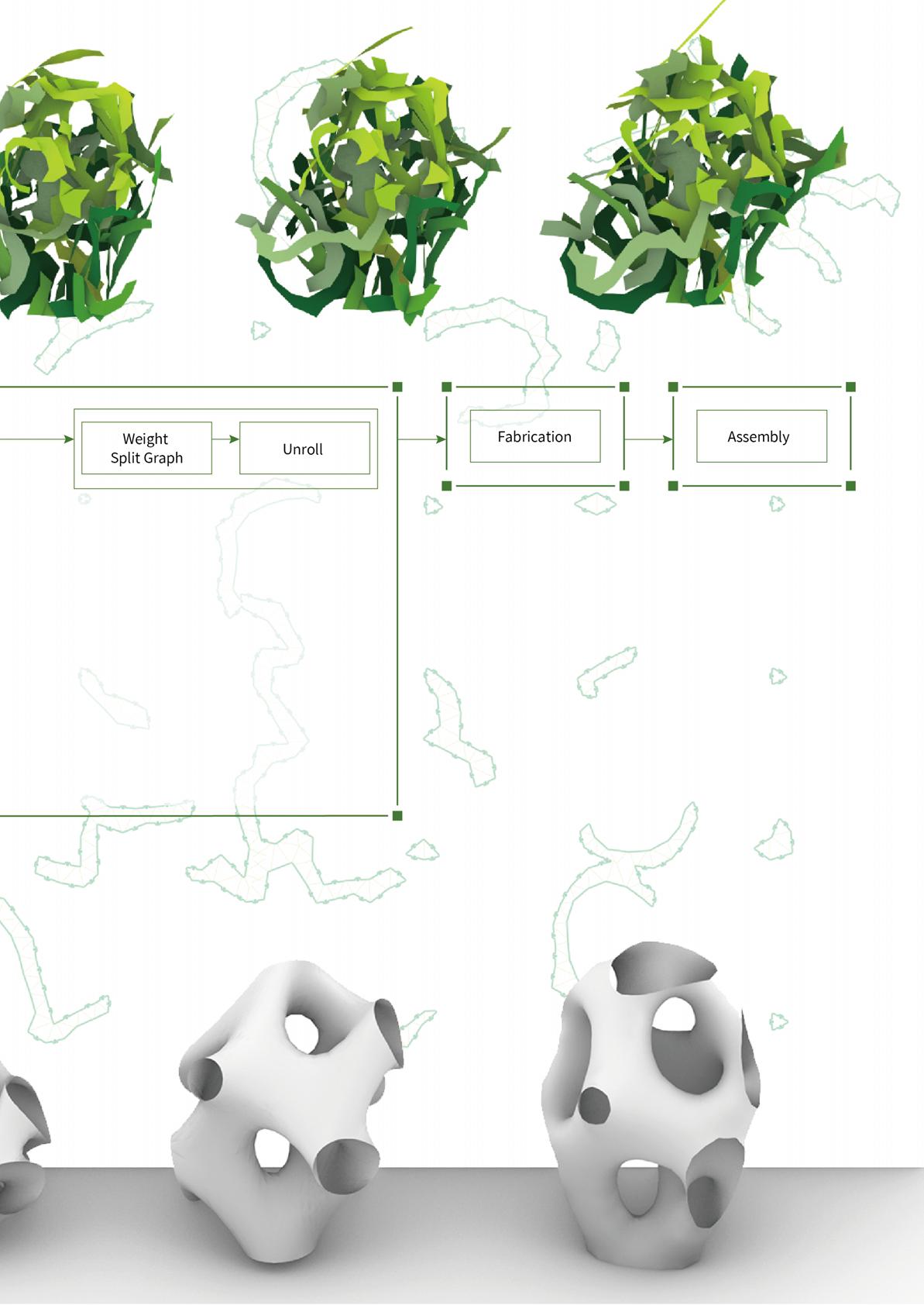 Fig.4-03 The unrolling of differential panel tiling
Description: Industry Cooperation project
Location: Taiwan
Institution: NCKU X CHIMEI | MODEX
Date: 2018
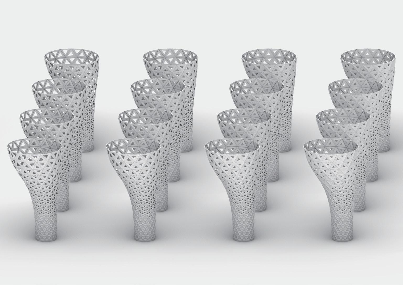
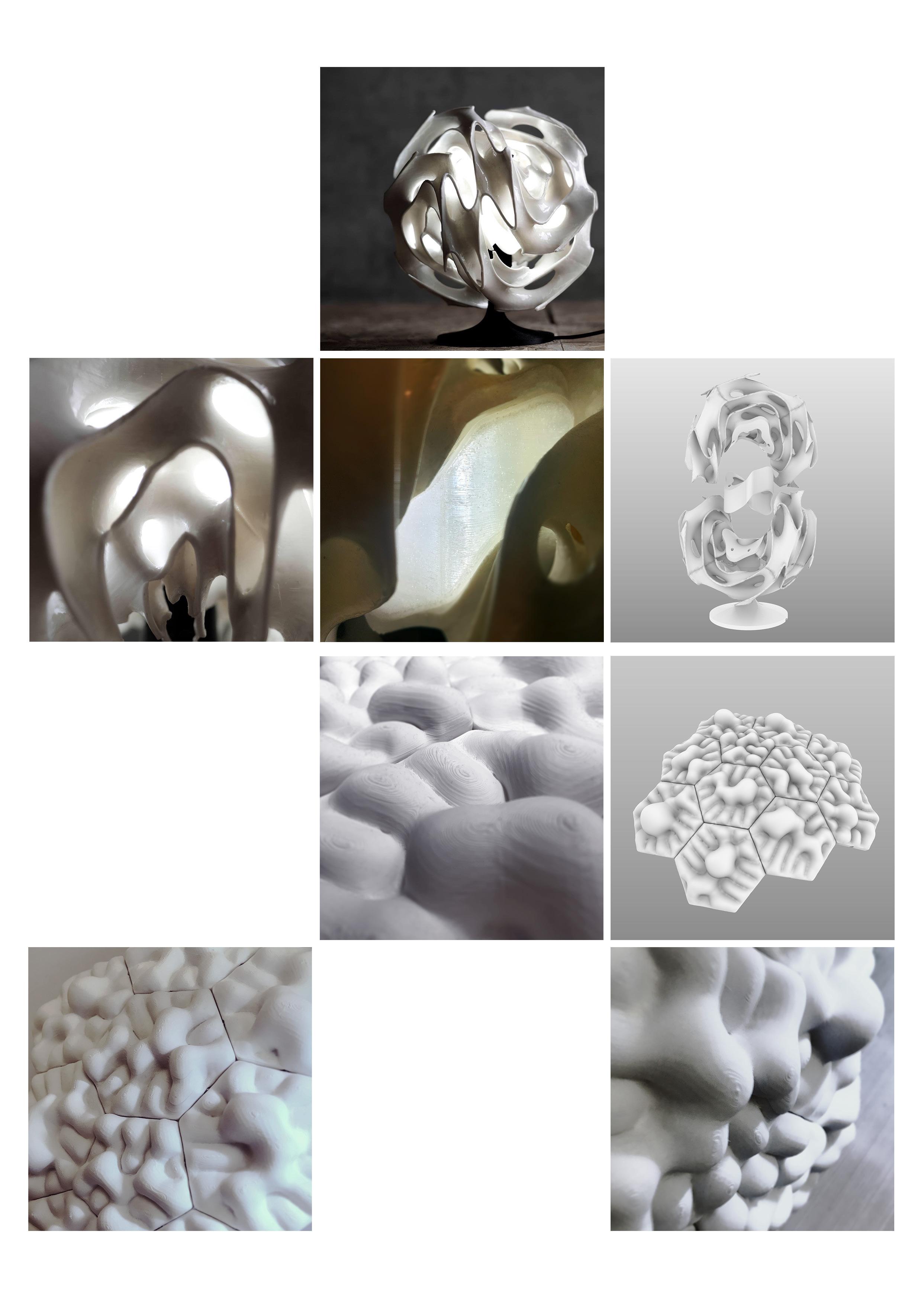
Enter the Void is a collaboration with the leading 3D filament brand CHIMEI | MODEX to promote the utilisation of 3D printing technology. The result was required to demonstrate the advantages of the 3D printing technique. The design is based on the mathematical form called GYROID. then, morphed on hyperbolic paraboloid to generate the complex geometry. Moreover, to consider the disassembly method of the complex geometry and the fabricating requirements.
Description: Individual works
Location: Taiwan
Date: 2021
The Puff Waffle is an individual study inspired by Andrew Kudless 's P wall. Trying to demonstrate the shape of the squeezed liquid.
Beginning with using the hexagon as the panel and making them tiling on the sphere. Then, generated the differential growth curve on each panel and let them be the restricted paths on the panels. Finally, inflating each hexagon panel.
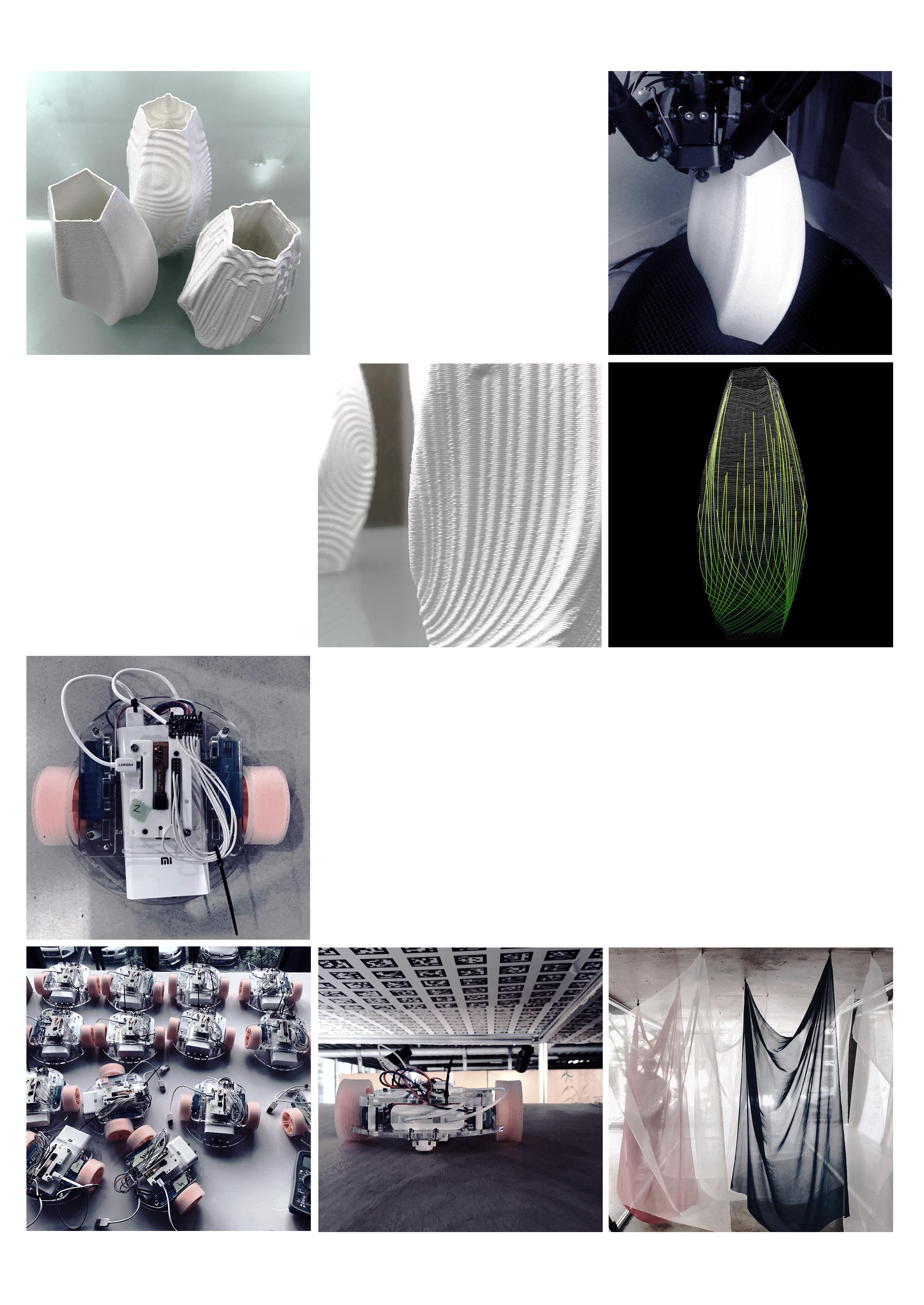
The EggShell is the individual creative work to explore the extremely thin 3D printing product. One of the interesting patterns was generated by the agents. First, the agents were arranged at the bottom and restricted on the surface. Then, gave them the force of movement and recorded it. Finally, the printing path was designed as a continuous curve to achieve no seam profile and directly generate G-code by grasshopper to control the various parameters such as movement speed and extrusion quantity.
Description: Individual works
Location: Taiwan
Date: 2020
Description: Workshop by Digital Future
Tutors: Maria Yablonina, Samuel Ledar
Location: Shanghai, China
Institution: CAUP Tongji University and Stuttgart ITECH
Date: 2019
Collaboration: Group Stuttgart ITECH
F5 is a project led by Stuttgart ITECH in a week-long workshop. The project explored the trend of collective robotic construction through the use of bespoke mobile machines to create adaptable spaces.
In the project, the participants were involved in the assembly, choreography, and installation stages of a bespoke robot system. Moreover exploring the choreography of the machine movements as it relates to physical space and human interaction.