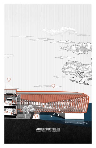
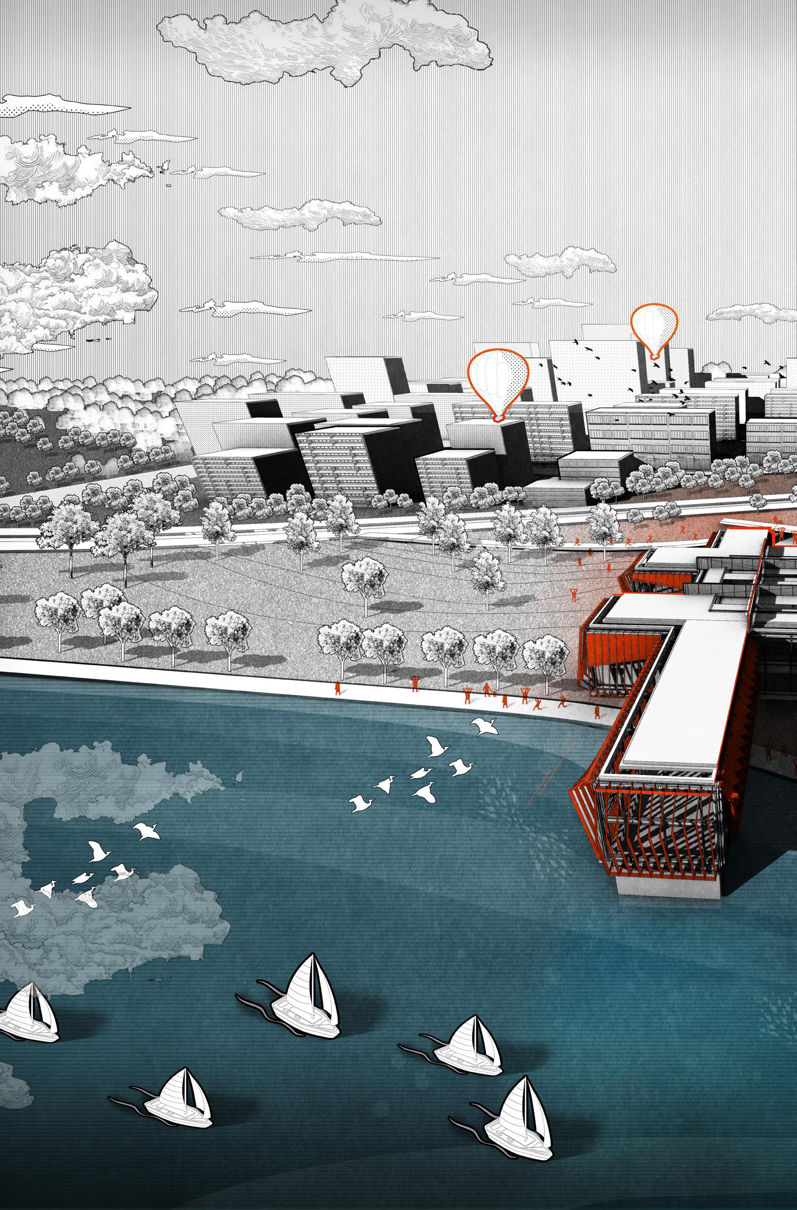
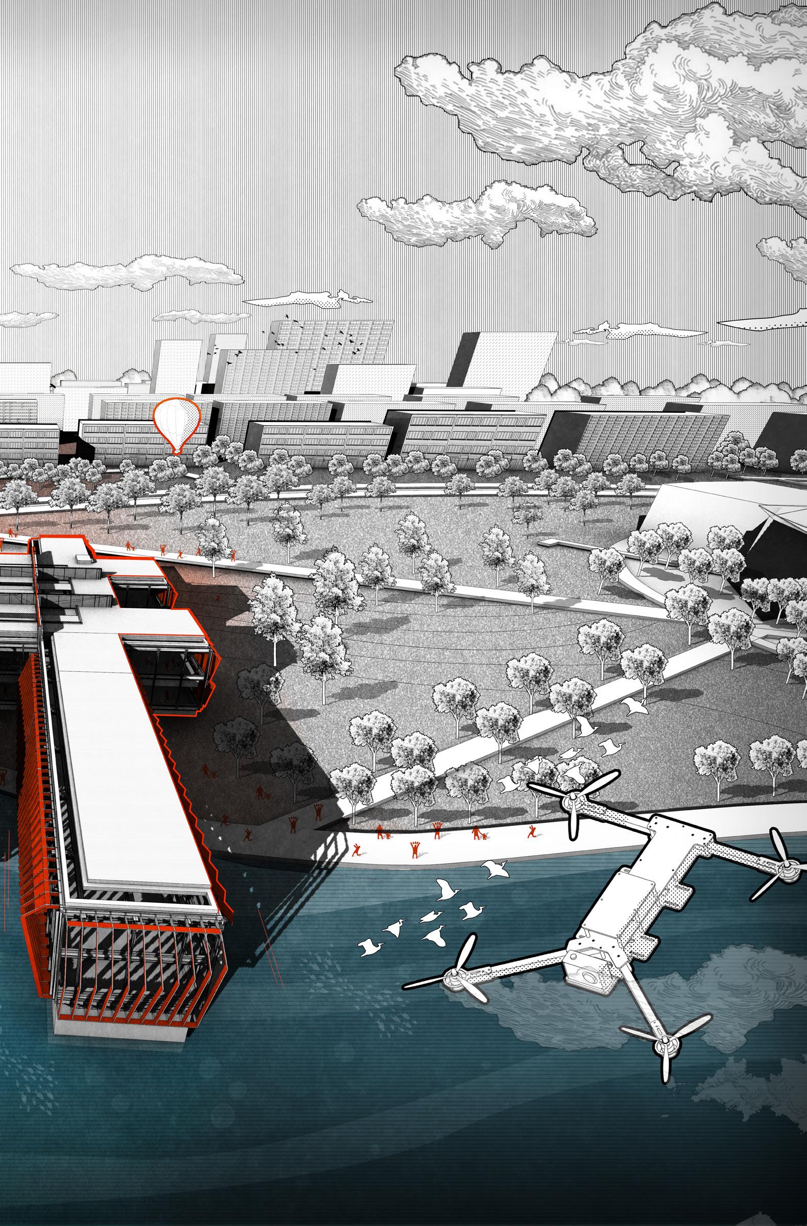
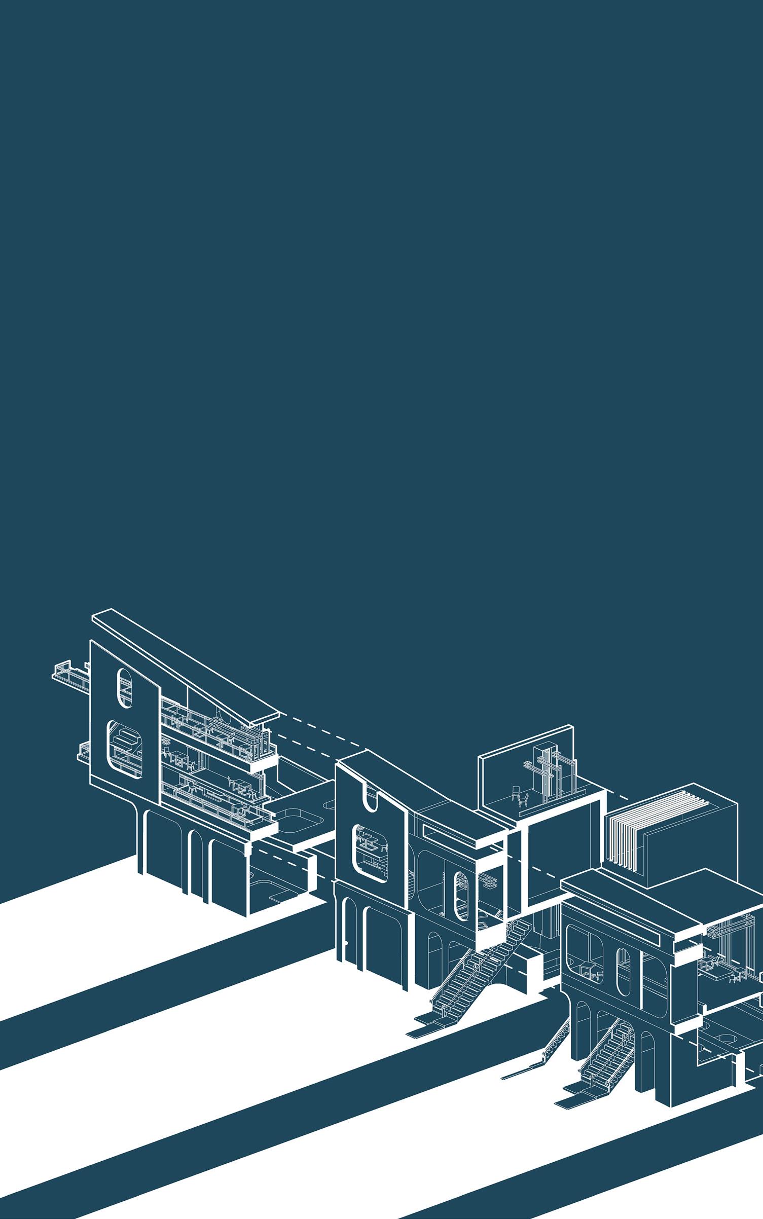
DUBAI BUSINESS BAY SEA LEVEL RISING CITY "FLOATING CAPSULE" TEMPE DOWNTOWN LAKE, ARIZONA, UNITED STATES 0 1
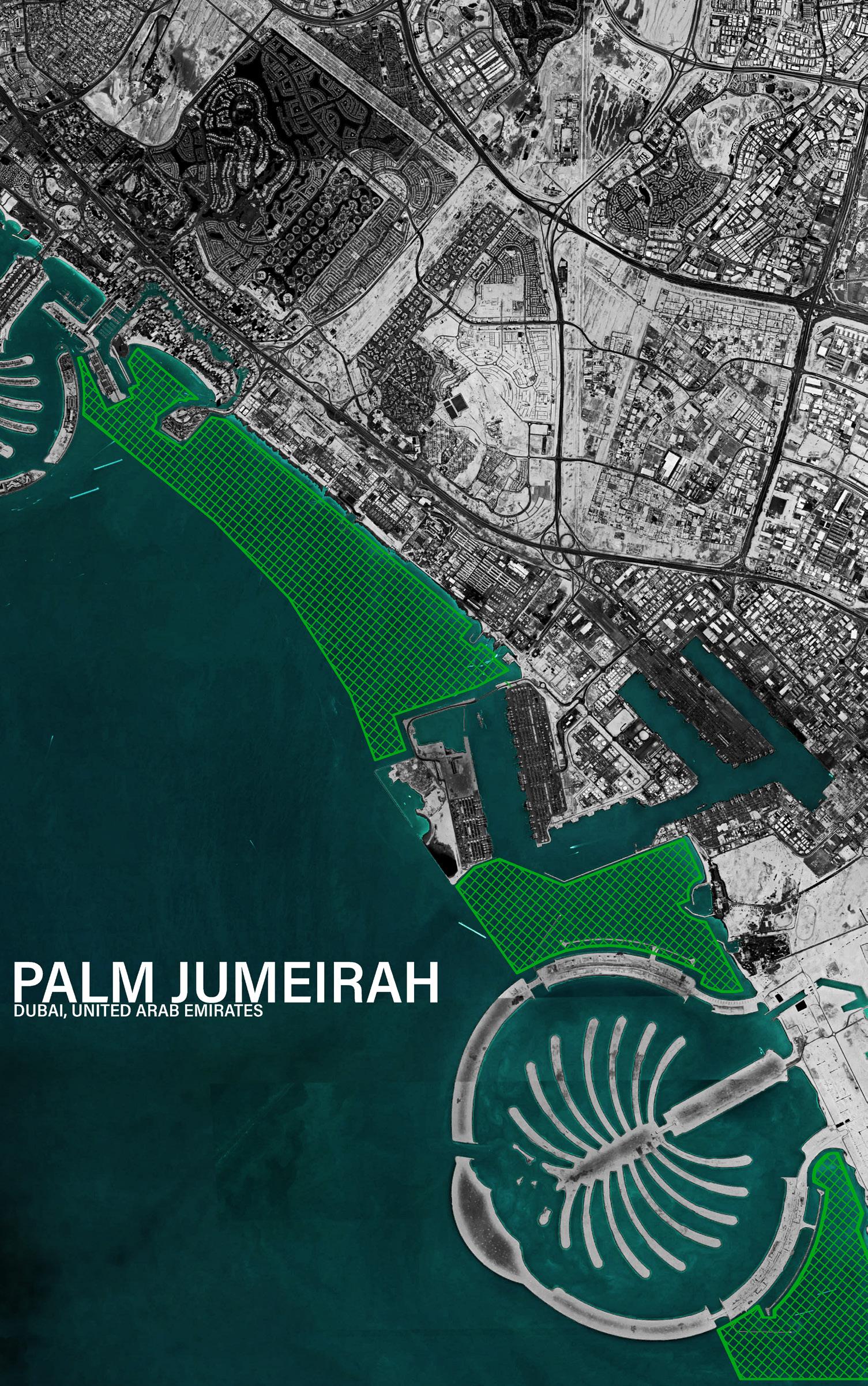
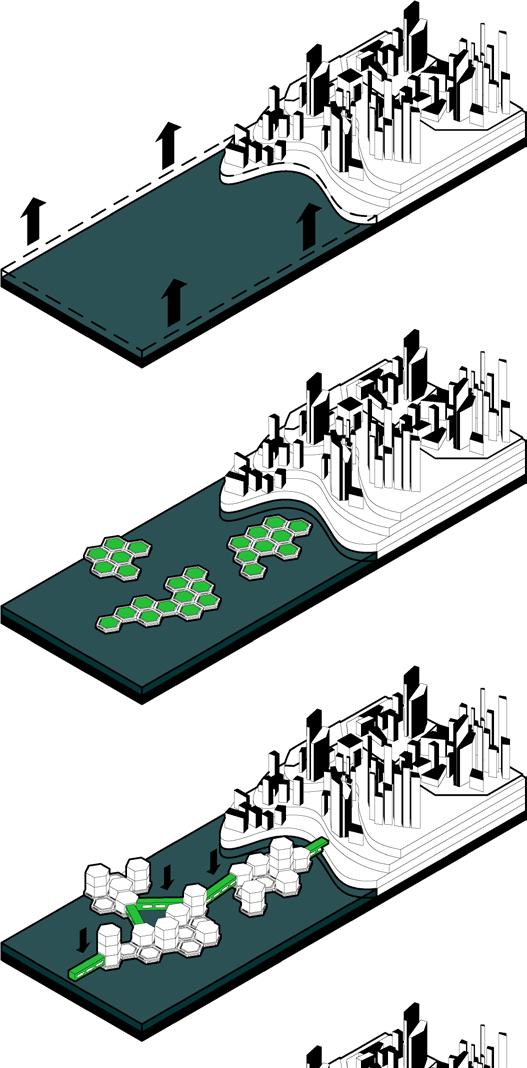
Sea level observation work began since 1850 in Dubai. According to the record, the average global sea level rise is at least 7 inches annually, and the rising rate has been accelerating since 2000. As one of the world's most highly developed coastal areas, sea level rise is an urgent problem to be solved.
JUMEIRAH ISLAND
JEBEL ALI
WATERFRONT
ATLANTIS DUBAI
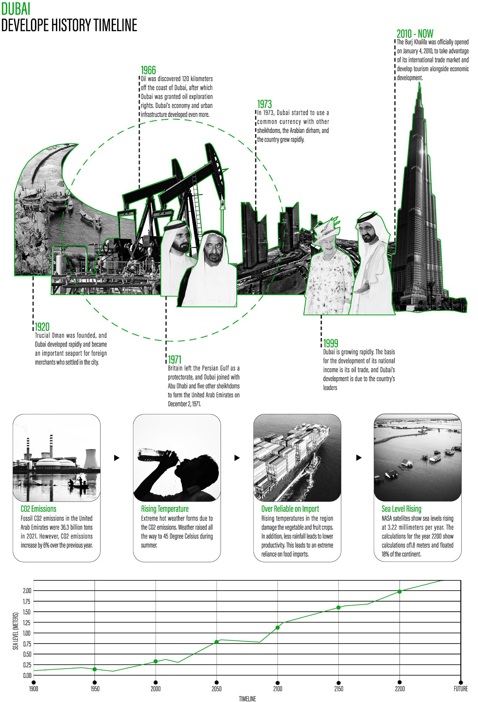
Dubai signed a basic peace treaty with the British, The Permanent Armistice, as an important port for foreign merchants who settled in the city.
TIMELINE
SOLUTION
Although different countries have different policies to reduce carbon emissions, I think developing marine life is a better solution.
UNITS PROTOTYPE
STEP 1 STEP 2
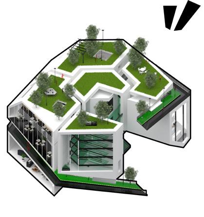
Sea level rising due to the global warming. Some of the costal building already covered by water.
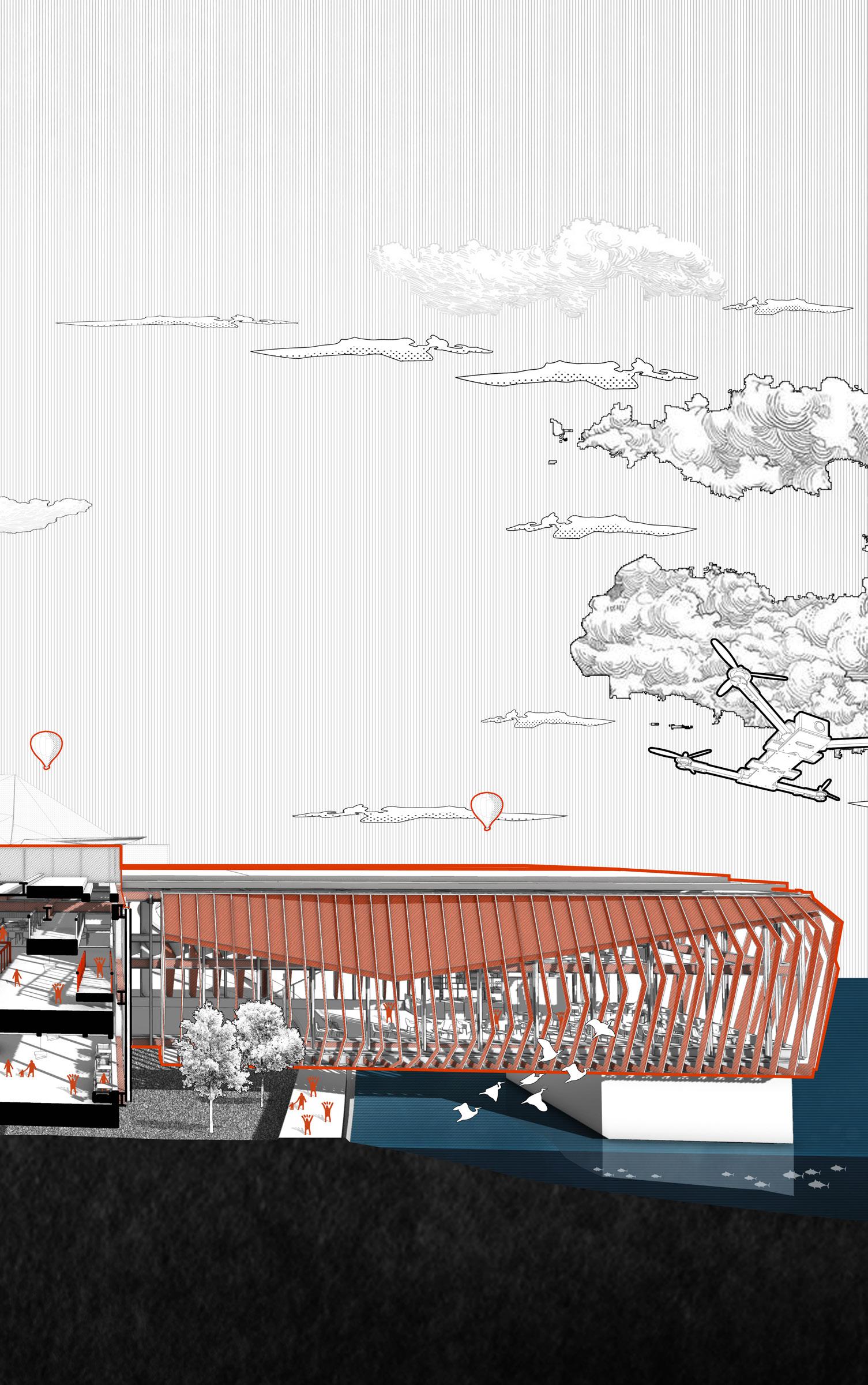
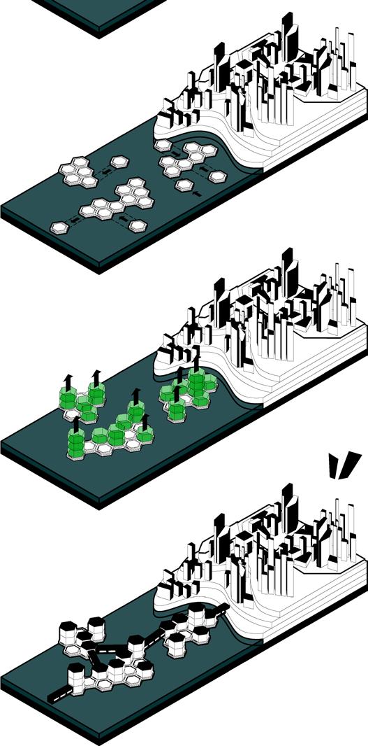
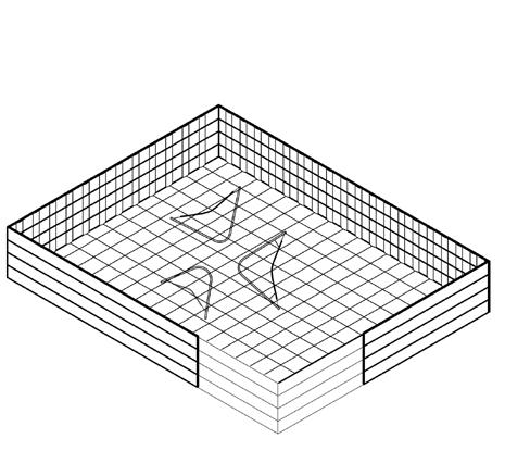
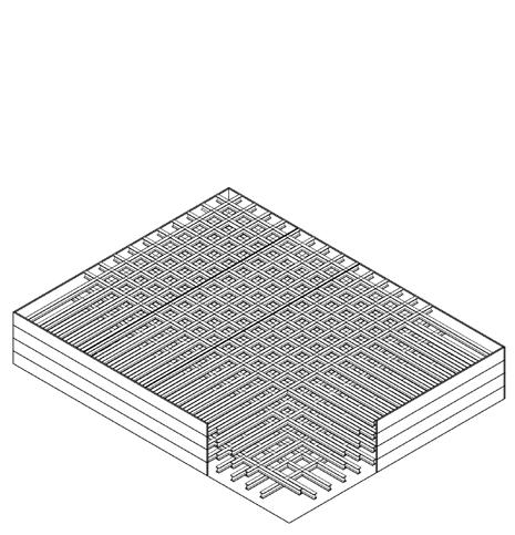
Hexagonal Floating Platform with Algae Bioreactor in order providing spaces above the ocean and energy supply.
STEP 3 STEP 4
The carbon negative cement can be used as a construction material of the floating unit.
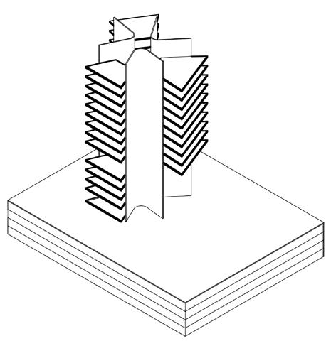
The cluster will be built above the hexagonal platform to provide living spaces and form aggregation.
STEP 5 STEP 6
Finished
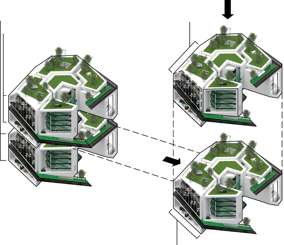
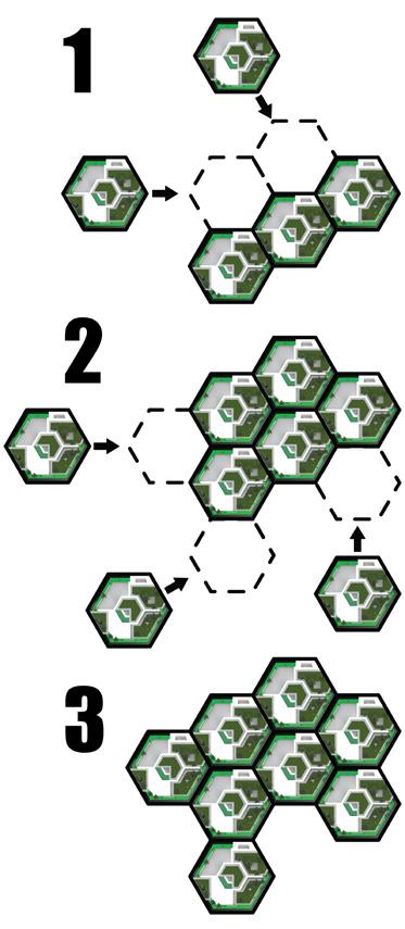
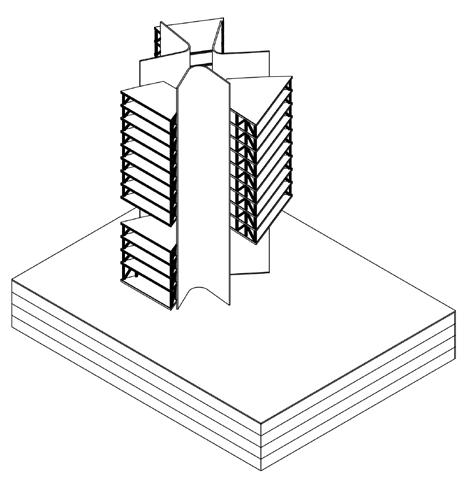
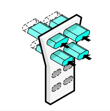
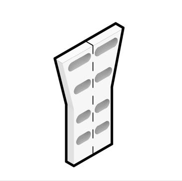
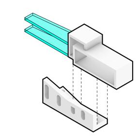
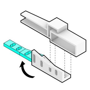
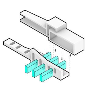
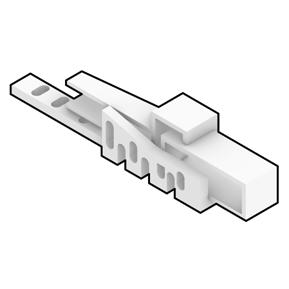
The hexagonal shape is the strongest, allowing the unit to stay in place in the ocean instead of floating in the wind. It also offers the possibility of rapid composition.
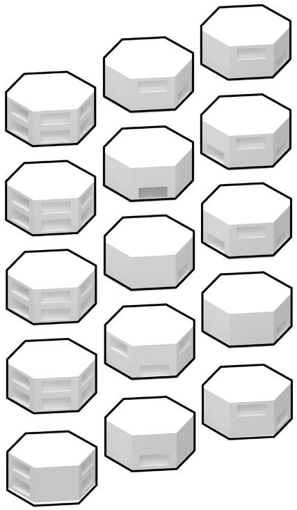
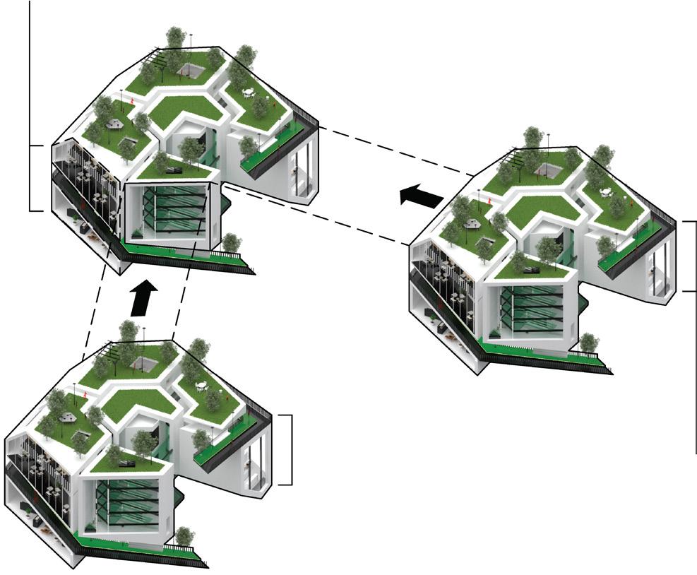
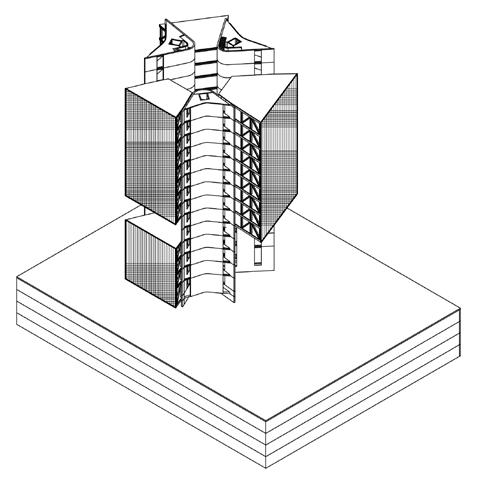
PRT will be formed as a transportation system between the cluster and form an entire community. 15 units with different combinations were generated and combined into one. It includes facilities for essential needs and new energy for suitability development.
DIFFERENT COMBINATIONS
Although different countries have different policies to reduce carbon emissions, developing marine life housing projects can be a solution to this problem.
Hexagonal floating platform with Algae Bioreactor in order providing spaces above the ocean and energy supply.
The hexagonal shape is the strongest, allowing the unit to stay in place in the ocean instead of floating in the wind. It also offers the possibility of rapid composition.
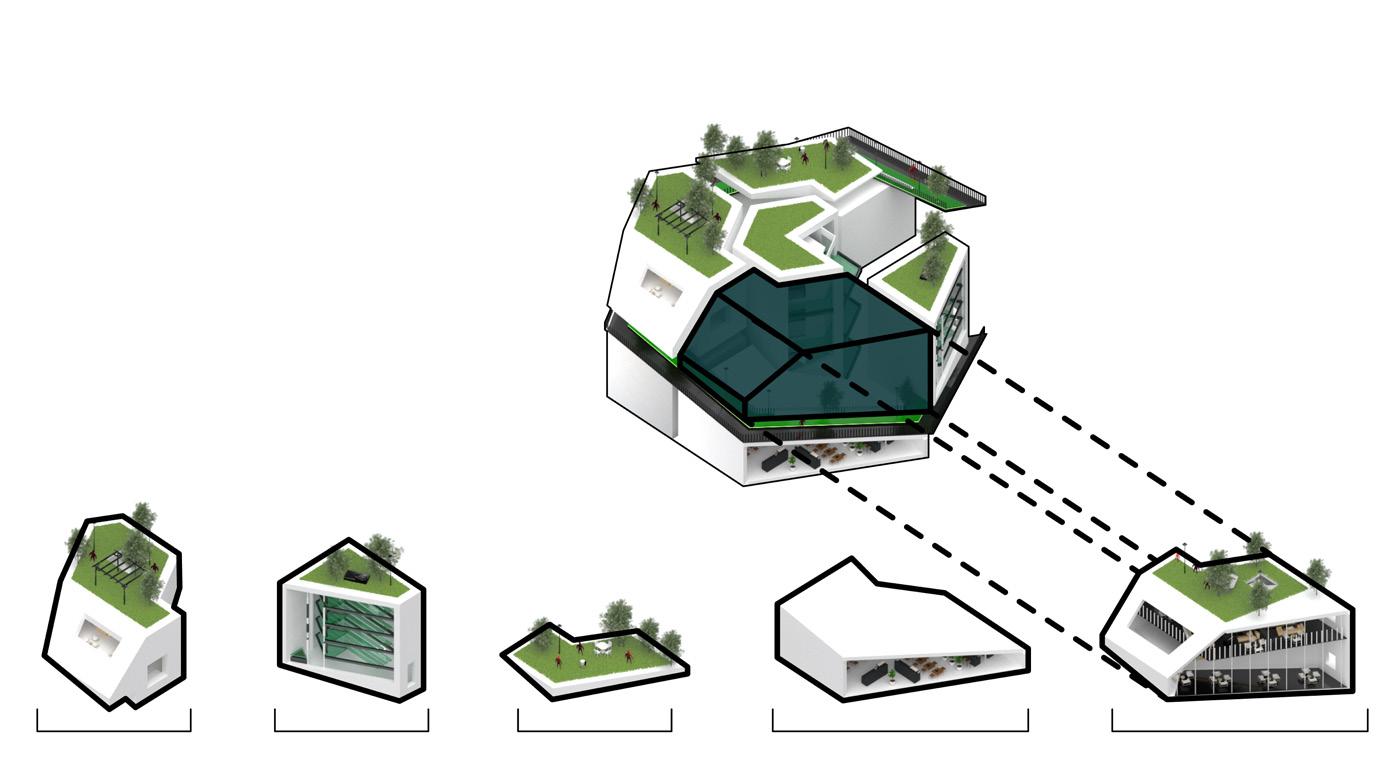
X, Y-Axis Connection
It can be combined quickly from the plane, and with the hexagonal plane, more hexagonal elements can realize hidden floating in the sea.
1.1
1.1
1.3
STEP 1
STEP 2
1.2
STEP 3
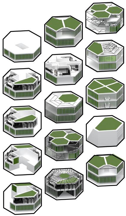
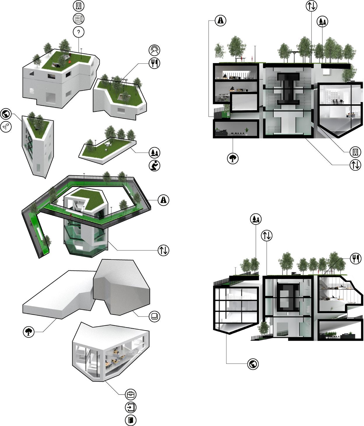
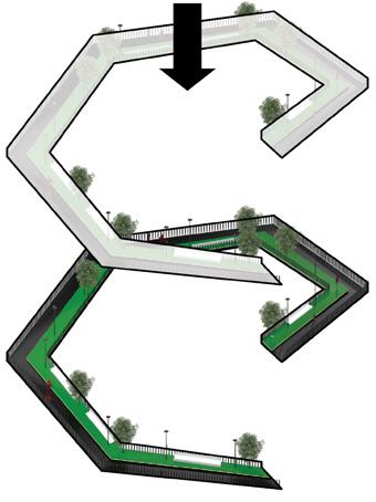
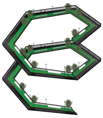
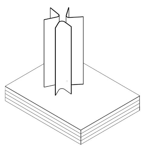
The green environment at the platform's top allows pedestrians to relax while providing enough oxygen.
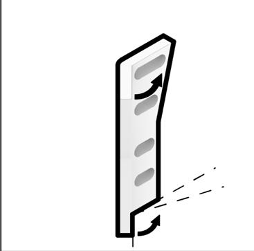
A spiral pedestrian passage in the unit is connected up and down to allow pedestrian circulation.
STEP 1
STEP 2
The upper and lower connection design allows the development vertically and horizontally, but the spiral pedestrian passage makes it the initial shape of the three-dimensional city.
BLOCK
BLOCK
BLOCK
BLOCK 2.2
BLOCK 2.1
BLOCK 1.1
BLOCK 1.2
BLOCK
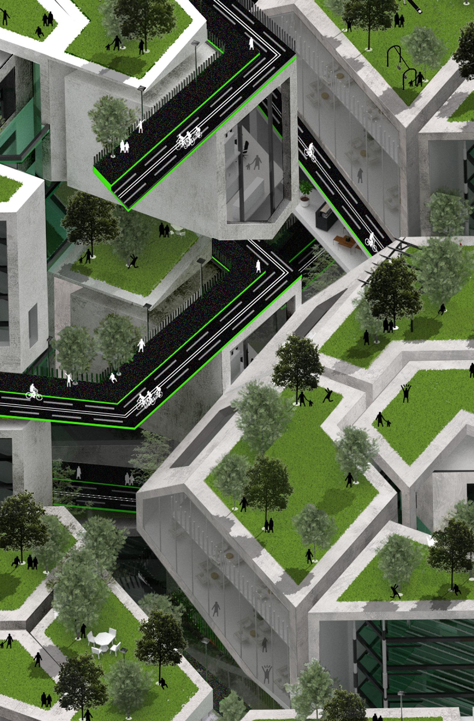
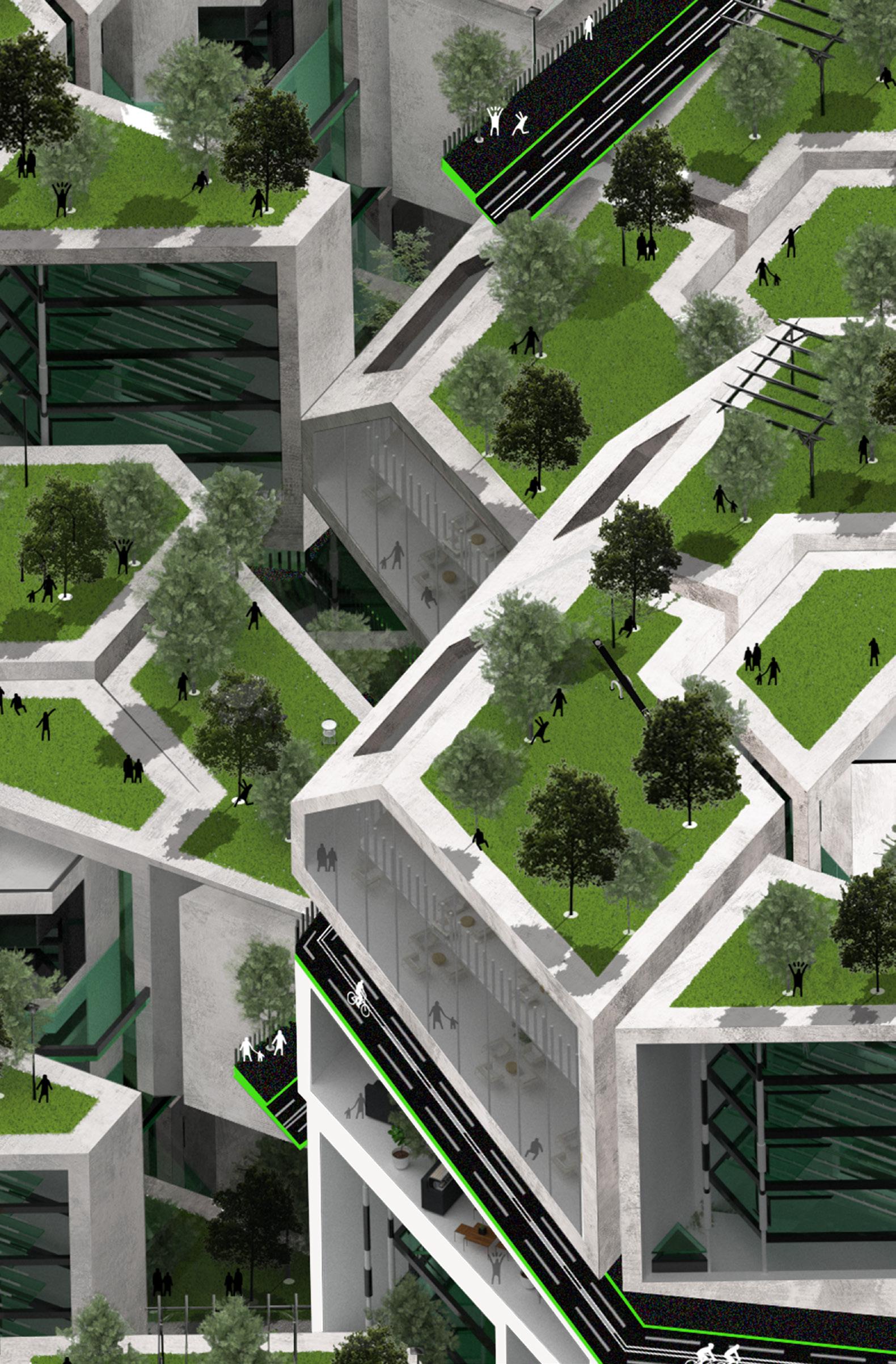
The sea unit can float with the rising sea level, and even after 100 years, when the sea has submerged part of Dubai land, human beings can still live on the sea and coantinue human civilization.
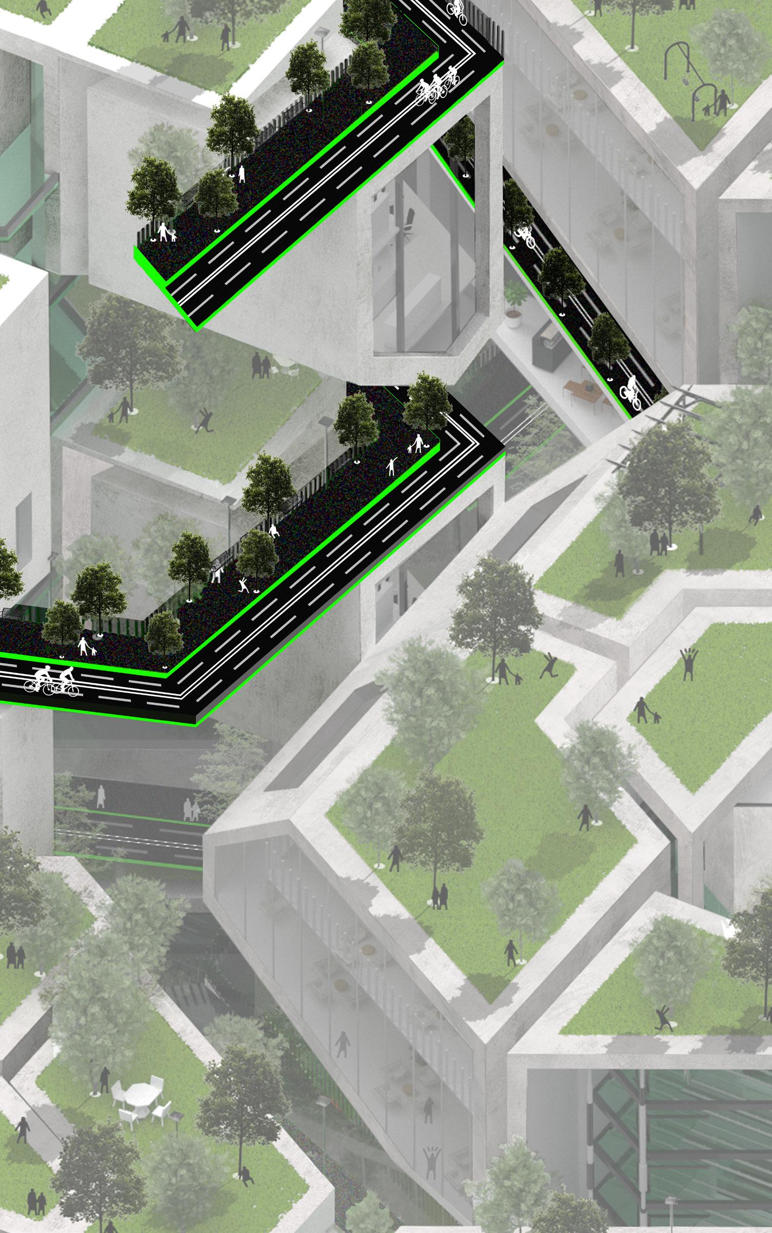
Pedestrian Lanes
Bicycle Lanes
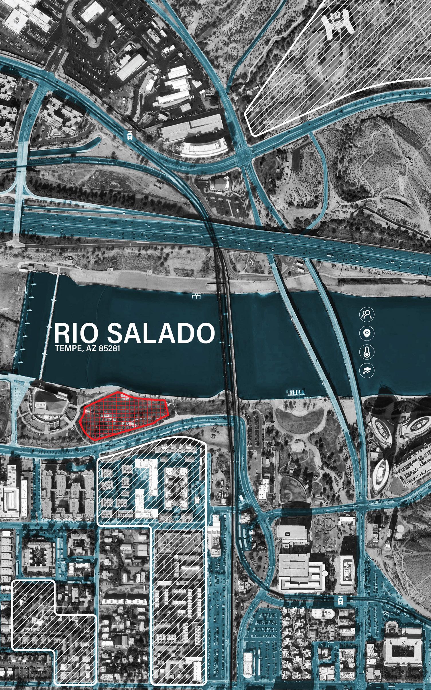
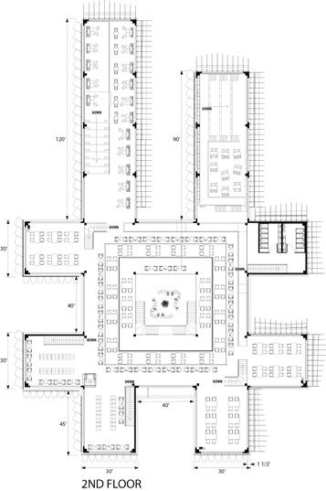
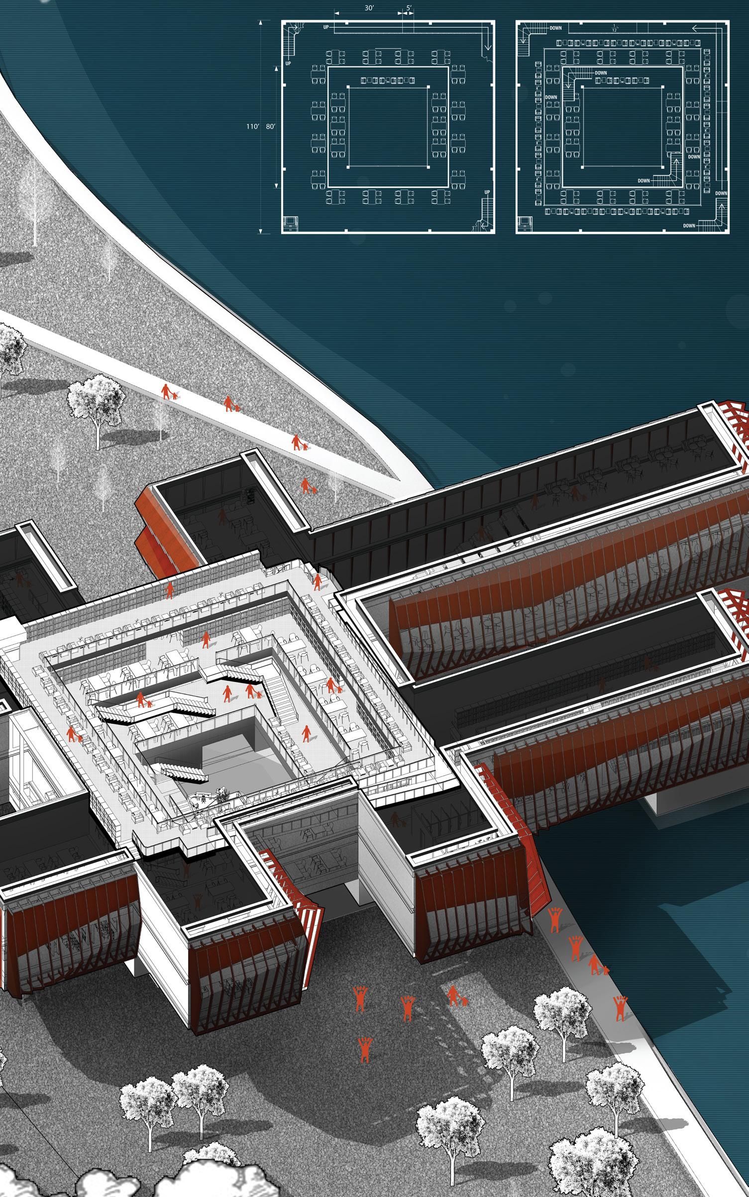
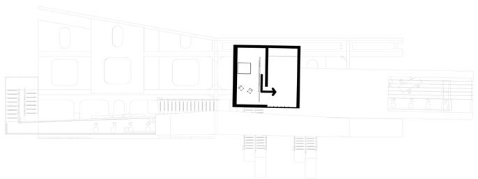
ARIZONA TEMPE DOWNTOWN THE "GRID"
ARIZONA TEMPE DOWNTOWN LAKE LIBRARY DESIGN
Architecture has officially stepped into the era of parametrization since the 21st century; Such as the breathtaking ZAHA HADID exaggerated curved design. Although pursuing new structures and appearances is an inevitable process of the era's evolution, The core concept of architecture is people-oriented. Therefore, I hope that I can get rid of the appearance of flashy architecture and discuss the impact of space on people from the most fundamental.
POPULATION
180,587
LOCATION
MARICOPA COUNTY
TEMPERATURE
HIGHEST: 115 F LOWEST: 15F
EDUCATION 22 ELEMENTARY SCHOOLS
THE GRID
Phoenix, the capital of Arizona, sits on both sides of the perennially parched Salt River, crisscrossing the flat city texture. The overall urban development has been on a fast track since the construction of a 5-nanometer semiconductor plant in the region in 2019, and residents are in urgent need of basic construction to cope with stability and development in the future.
GROUP INTERNATION
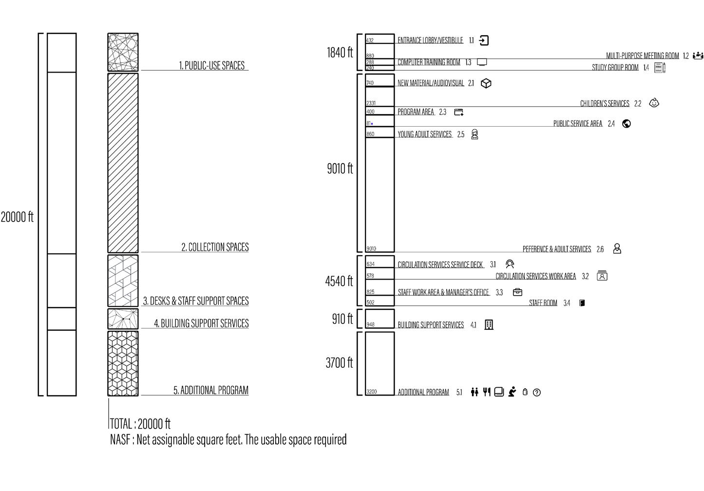
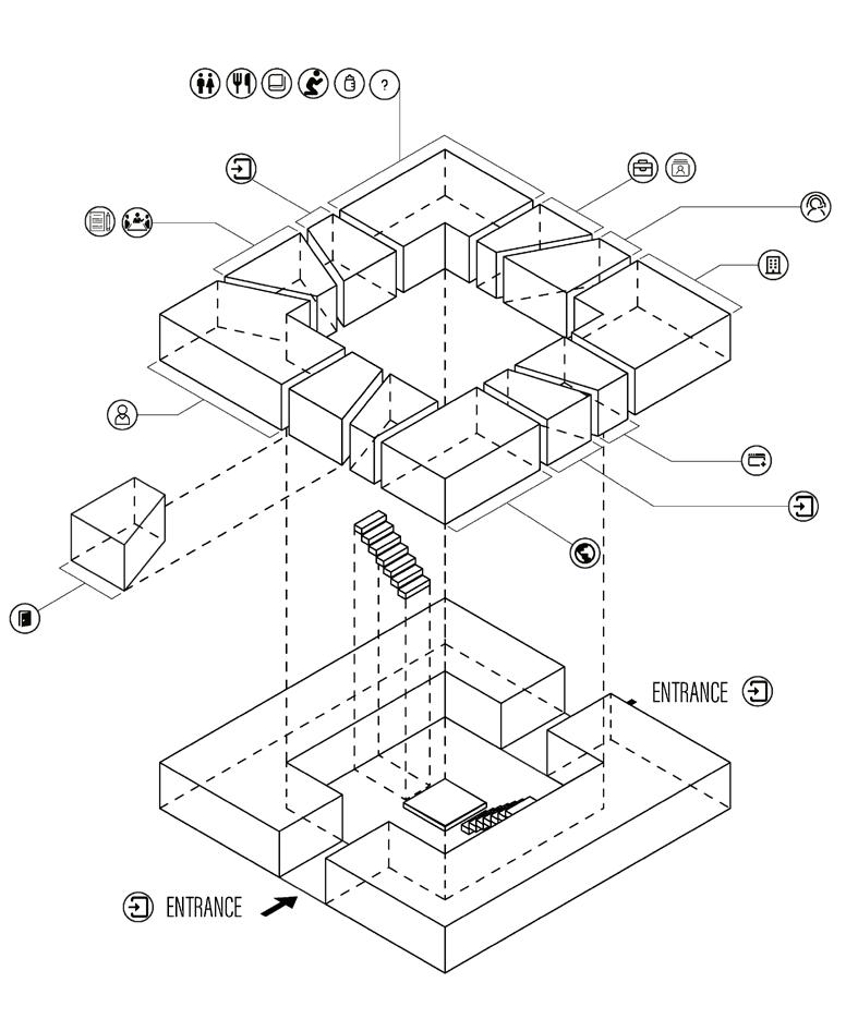
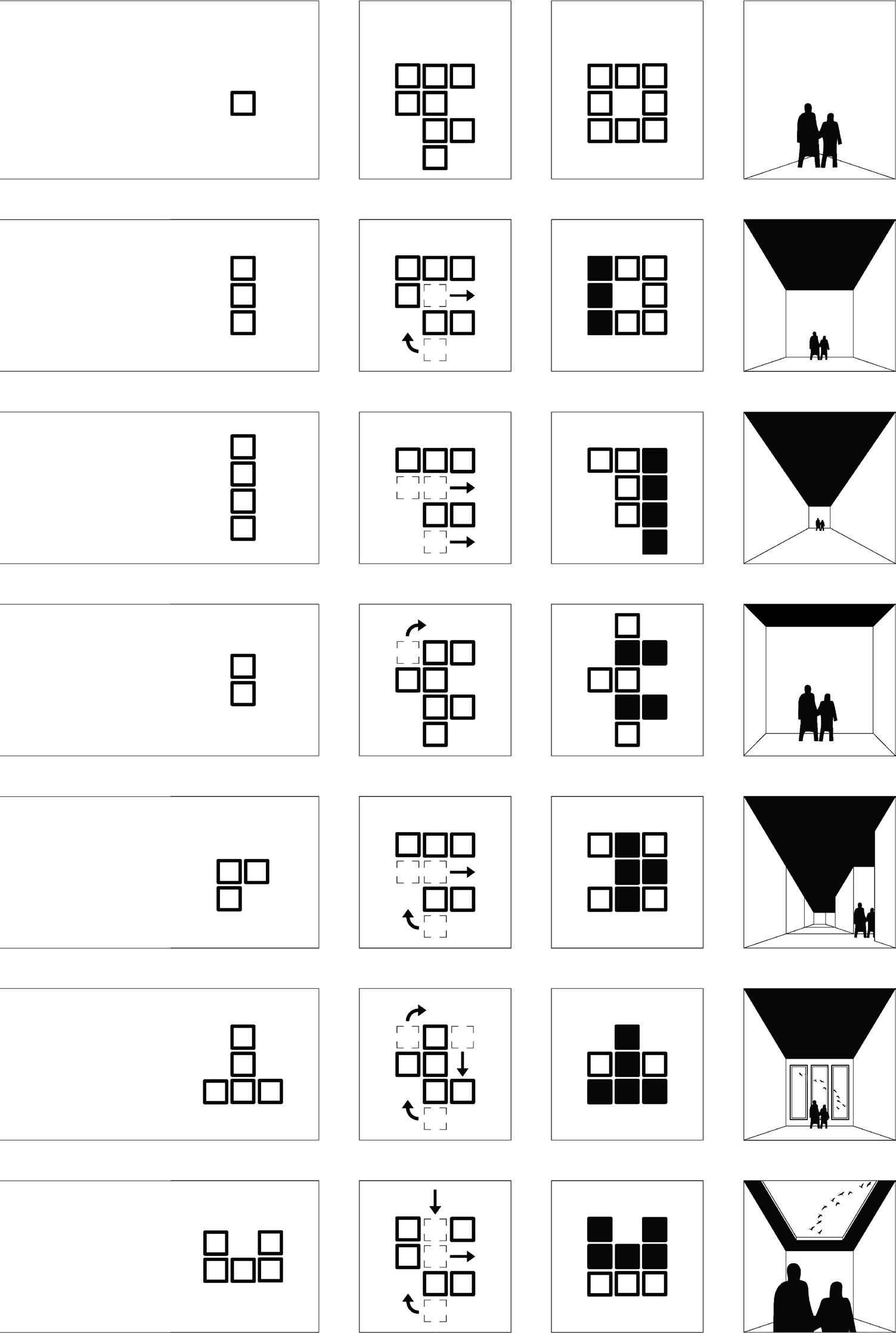
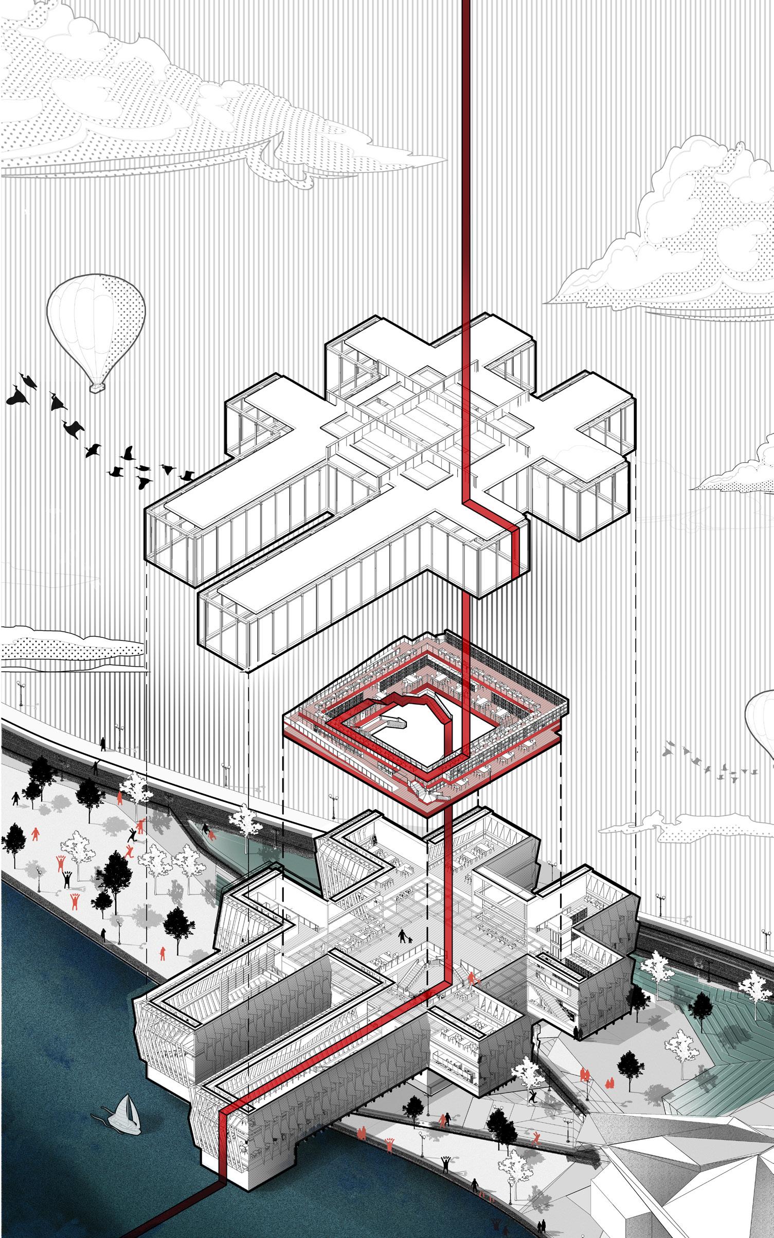
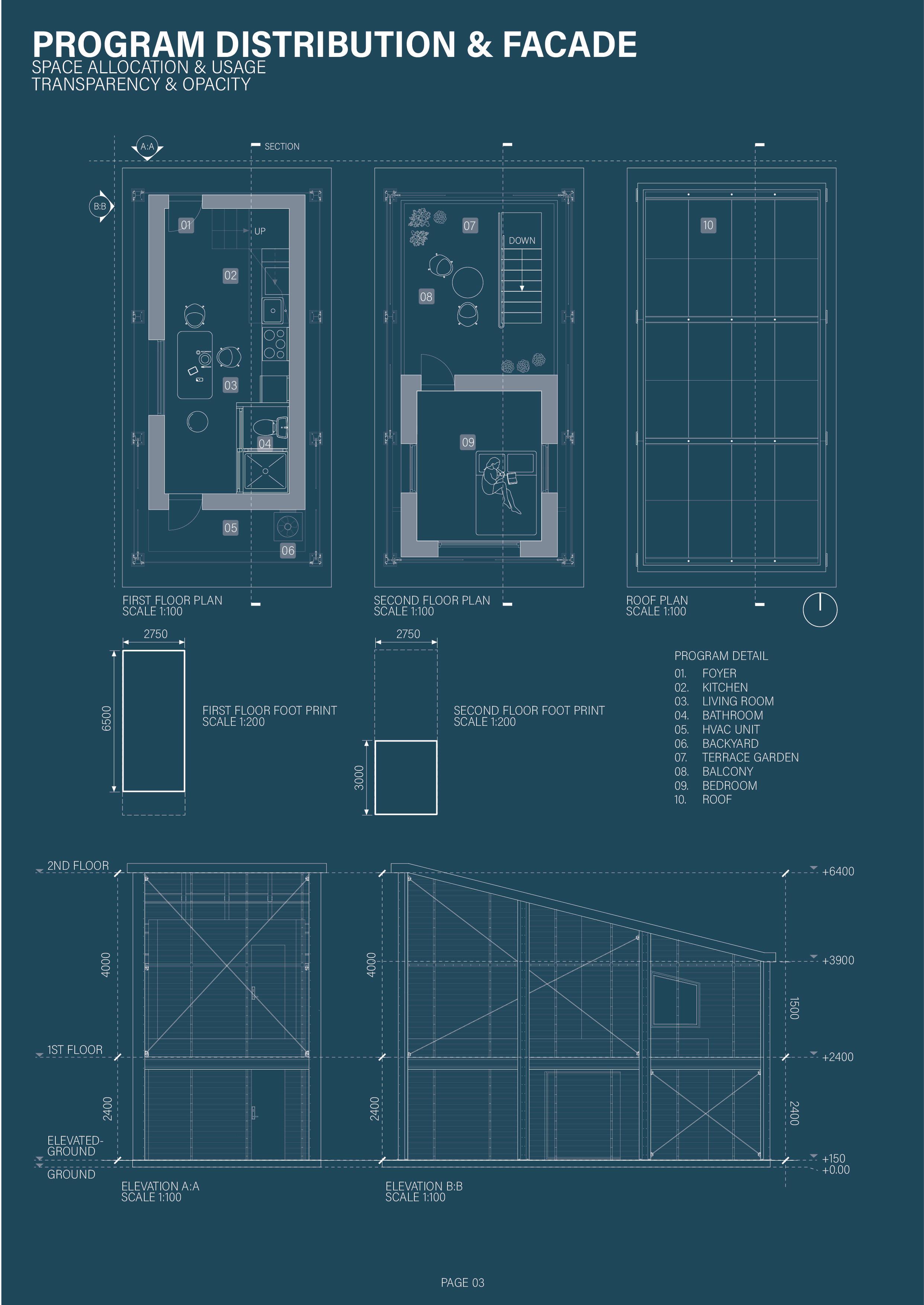
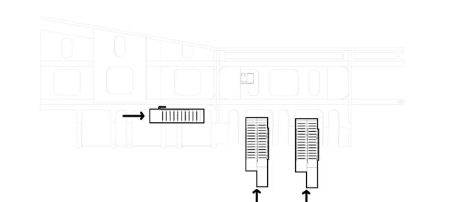
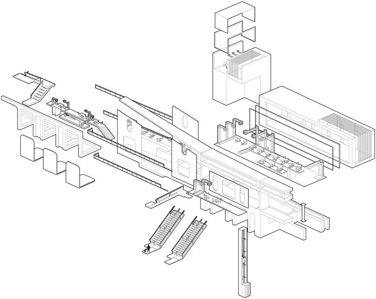
I think the present function of the library is no longer satisfied with providing books to read, so I put the library into three functional areas, namely, "Intersection," "Square," and "Deadline."
GRID
SQUARE
DEAD-END
SHAPES
MULT-USE SPACES
NORMAL SPACES
QUIET SPACES
TYPOLOGY
When entering a room, the size of the space, the ceiling heights, and the location of the windows can utimately affect the user's sense of space.
PROTOTYPE
CORNER
EXTENSION
ATRIUM
GRID
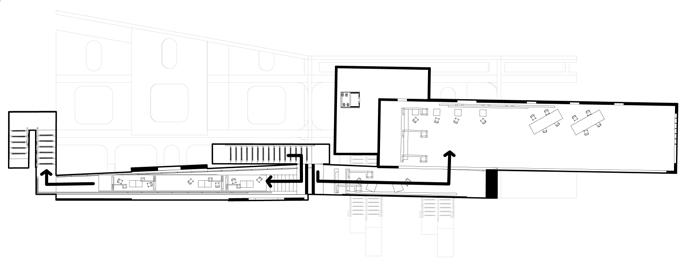
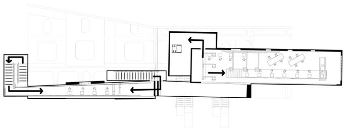
The grid design crisscrosses the interior spaces, making it easier for pedestrians to meet and communicate with each other.
SQUARE
The square design keeps the interior space around, which is more suitable for handling and placing books.
DEAD-END
The deadline design makes the interior space less contact with pedestrians in other spaces, which is suitable for visitors to read and work quietly.
LOBBY
COFFEE SHOP
The square design allows for books to be placed around the perimeter, and the hollow center allows the sun to shine into the underground levels.
QUIET PLACE
THE "DONUT"
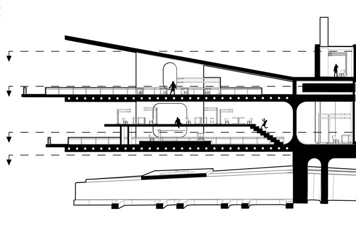
Different floors separate the noisy areas from the quiet areas. Compared with the traditional building structure, the hollow design makes the space more open.
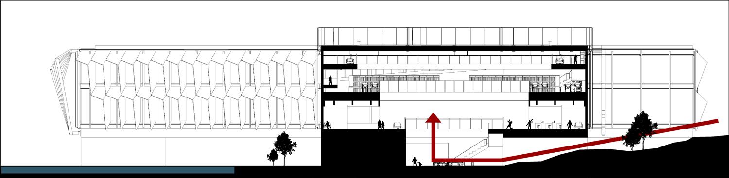
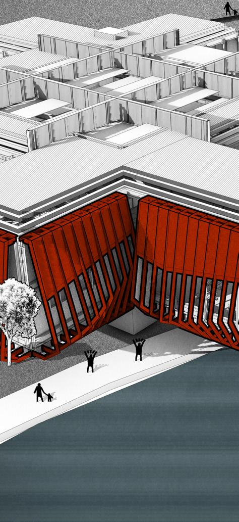
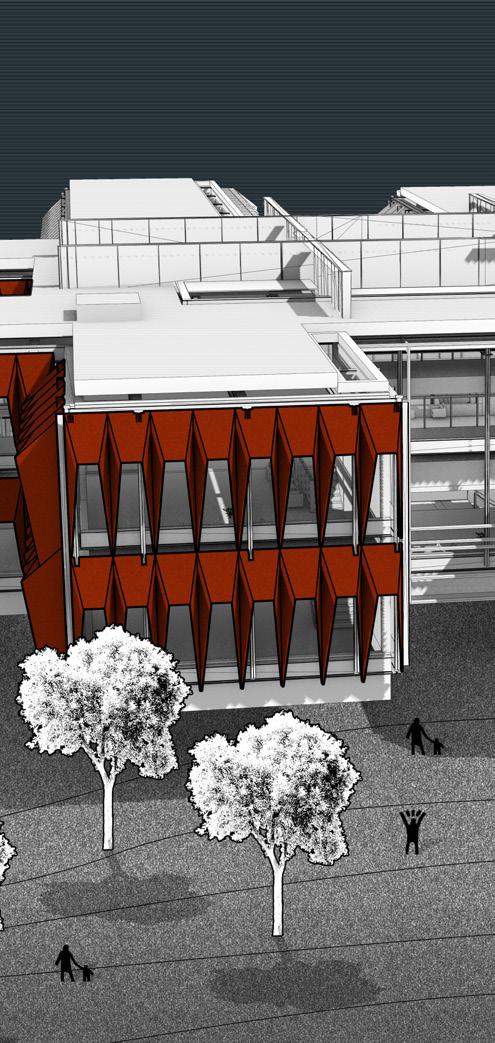
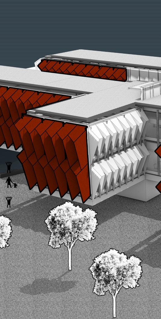
THE GRID
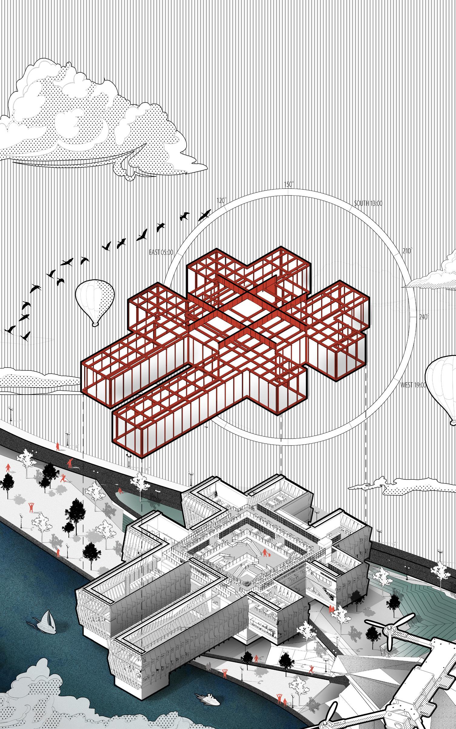
The CROWN HALL, designed by MIES VAN DER ROHE in 1960, is a famous modernism building using a remarkable steel structure with four crisscrossing main beams supporting the overall proposal, and no columns are required for the interior space.
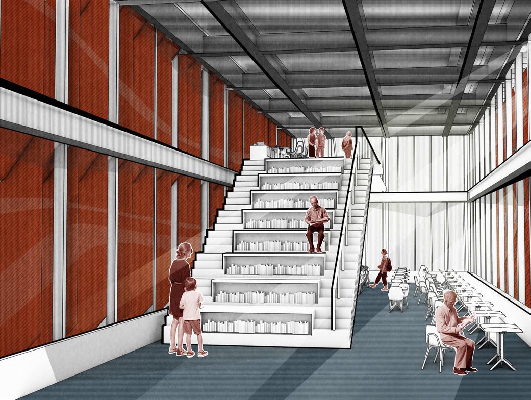
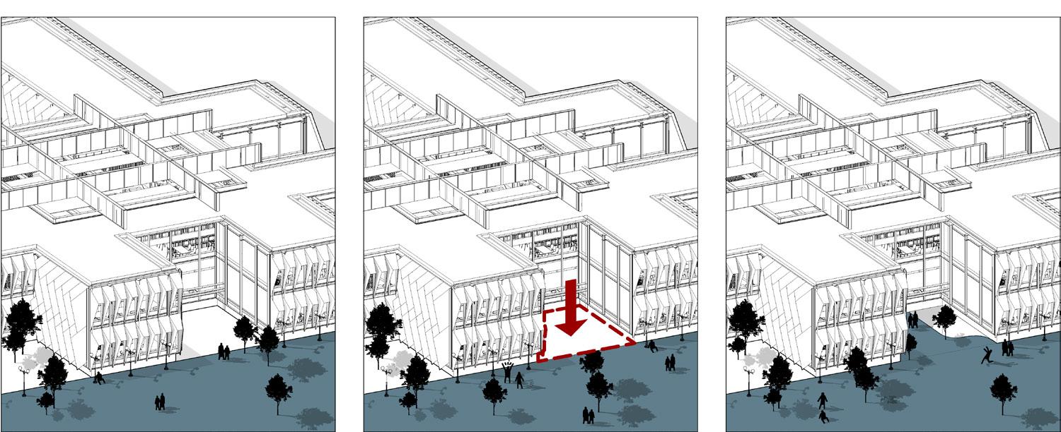
The library is built on a 10-foot-high hill. I arranged the entrance in the grid-gap, so that pedestrians can follow the hillside to enter the library, thus perfectly integrating the building with nature.
EAST SOUTH
Phoenix's temperature is around 120 degrees Fahrenheit, and the outer walls are insulated from the east.1111111111111111111
The bulging exterior walls can block the sun rays all day long without compromising the experience of viewing from inside to outside.
WEST
to dusk from the west.
The scaly exterior wall keep the sun out from afternoon
WINTER GREENHOUSE
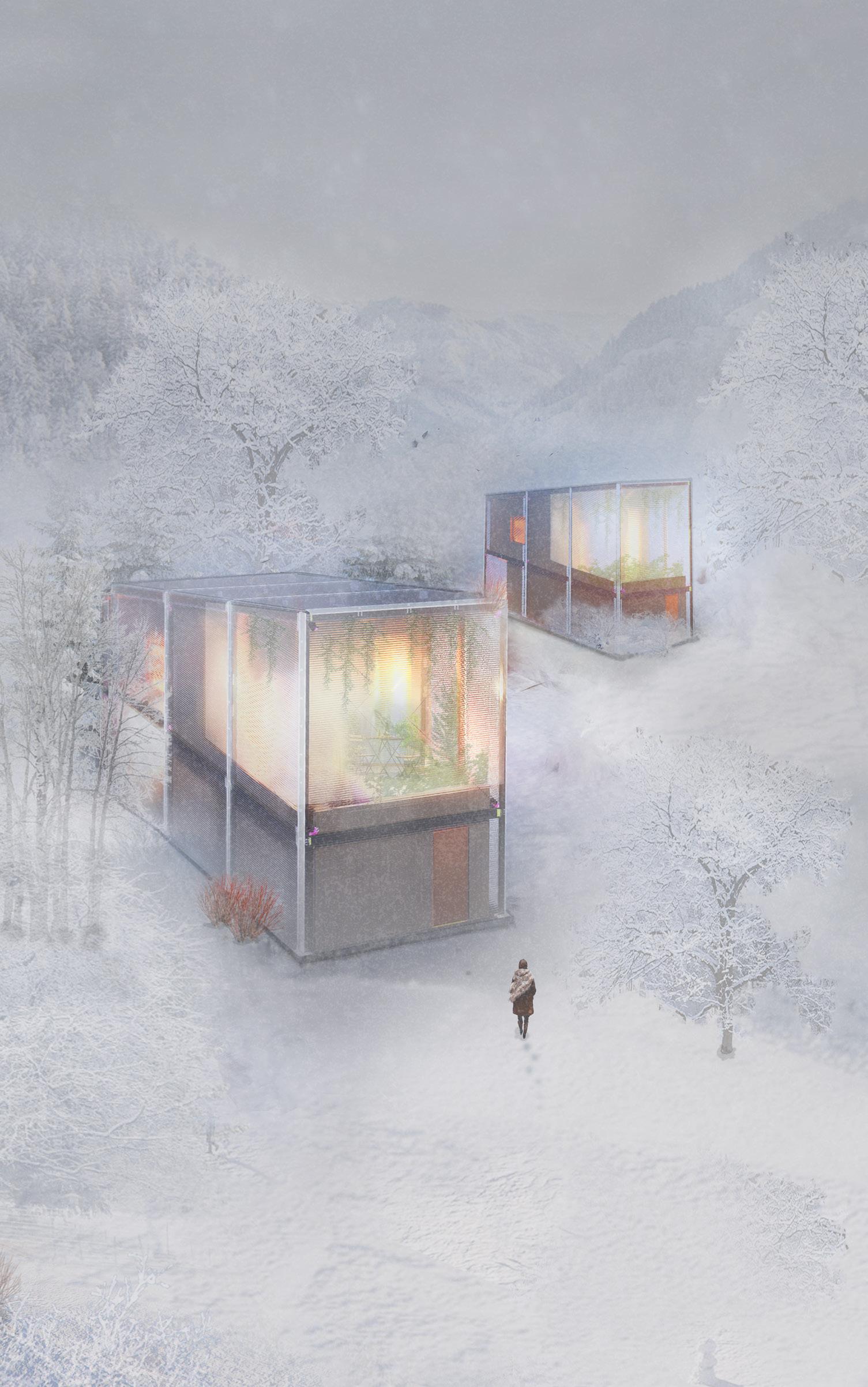
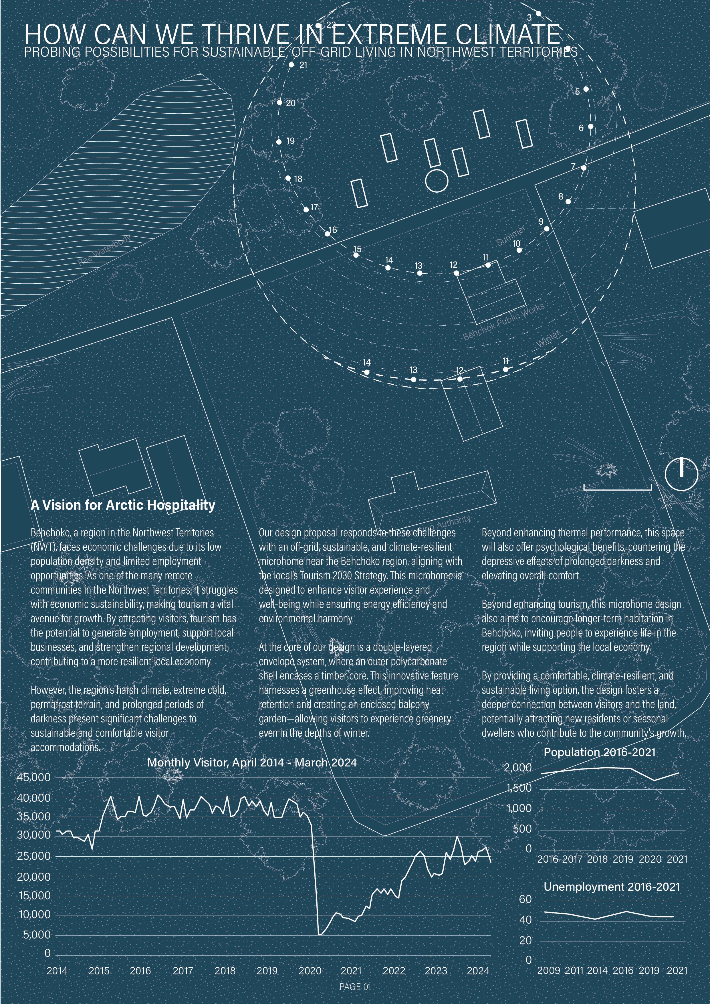
RAE BEHCHOKO, NT, CANADA
THE WINTER OASIS
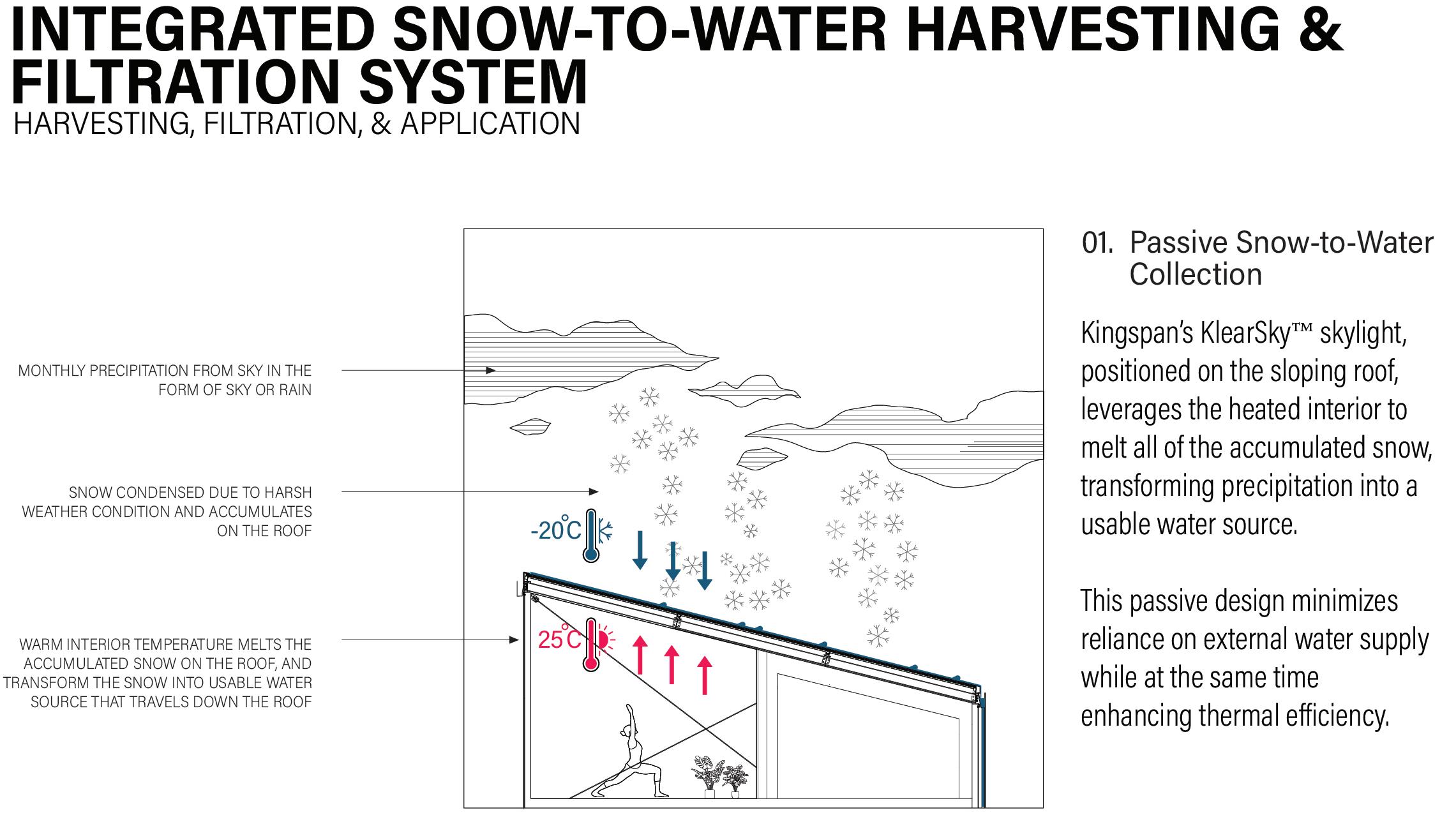
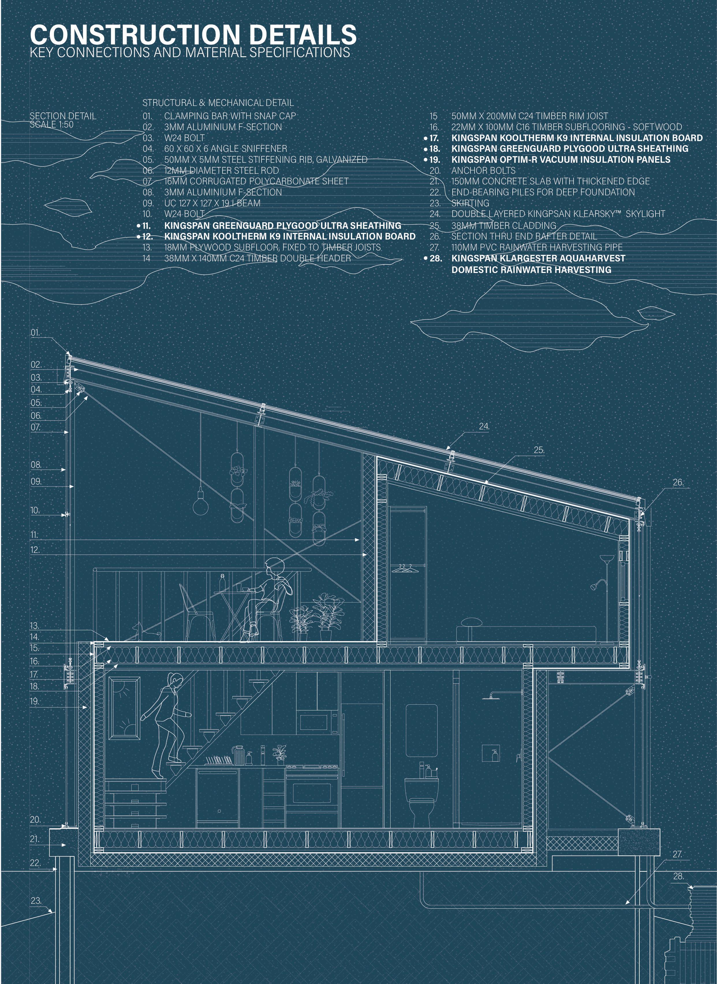
Inspired by greenhouse structures, the microhome features a double-layered envelope system, where an outer polycarbonate shell encases a timber core. This design passively retains heat and creates an indoor balcony greenhouse, allowing residents to experience natural greenery even in the depths of winter. The home fosters a balance between warmth and exposure to Arctic landscapes, mitigating the psychological effects of prolonged darkness.
DESIGN CONCEPT
The task was to design a sustainable and adaptable accommodation that aligns with the Tourism 2030 Strategy, supporting economic growth while integrating with the region’s natural and cultural landscape. The structure needed to withstand Arctic conditions while providing a unique, comfortable living environment for both short-term visitors and potential long-term residents.
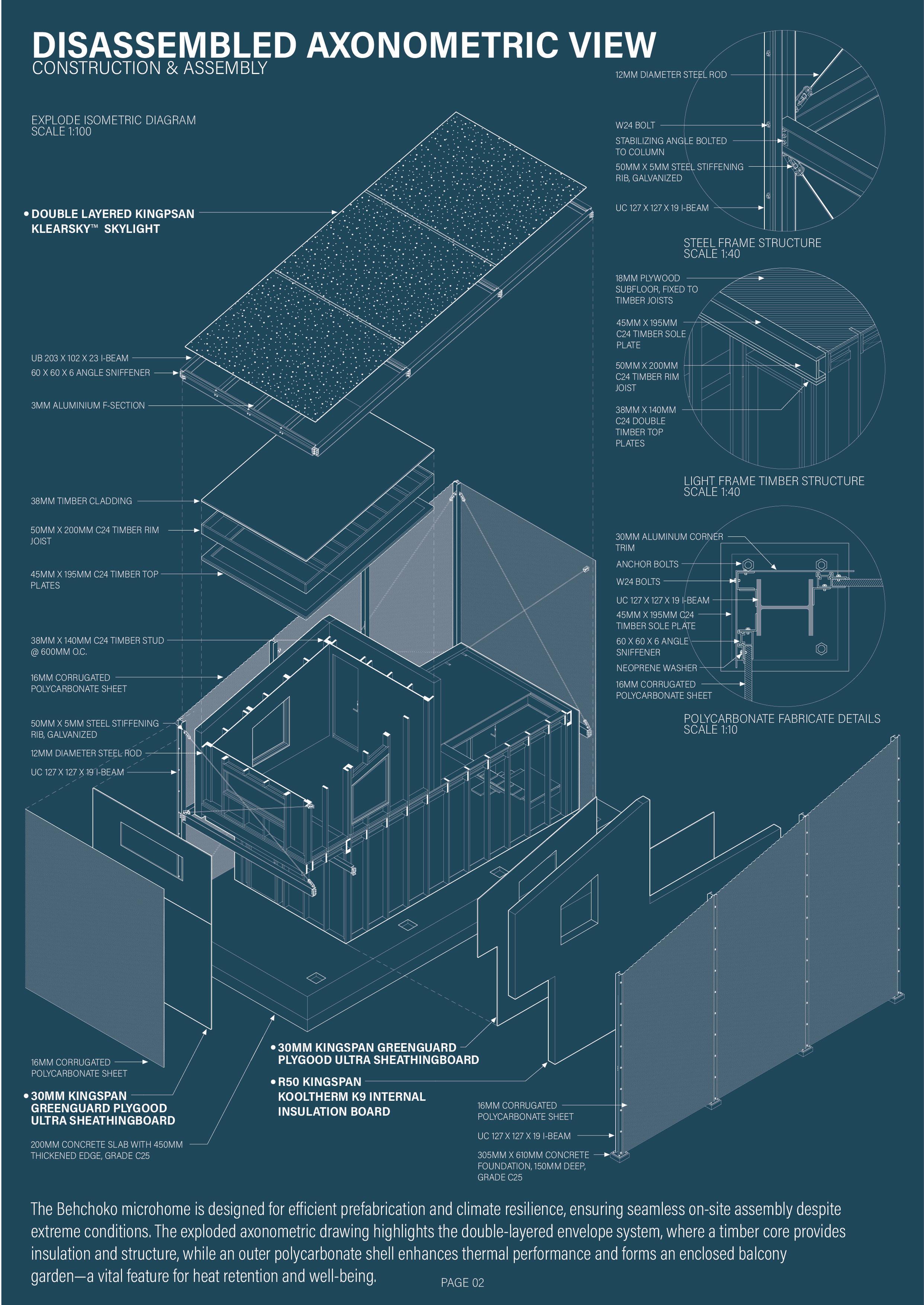
Double-Skin Envelope System
A polycarbonate outer shell and timber interior core create a thermal buffer, passively retaining heat
A semi-conditioned garden space enhances psychological well-being by maintaining greenery, even in Arctic conditions
Panoramic Aurora-Viewing Bedroom
The sleeping area is designed for unobstructed views of the Northern Lights, offering an immersive Arctic experience
Indoor Balcony Greenhouse
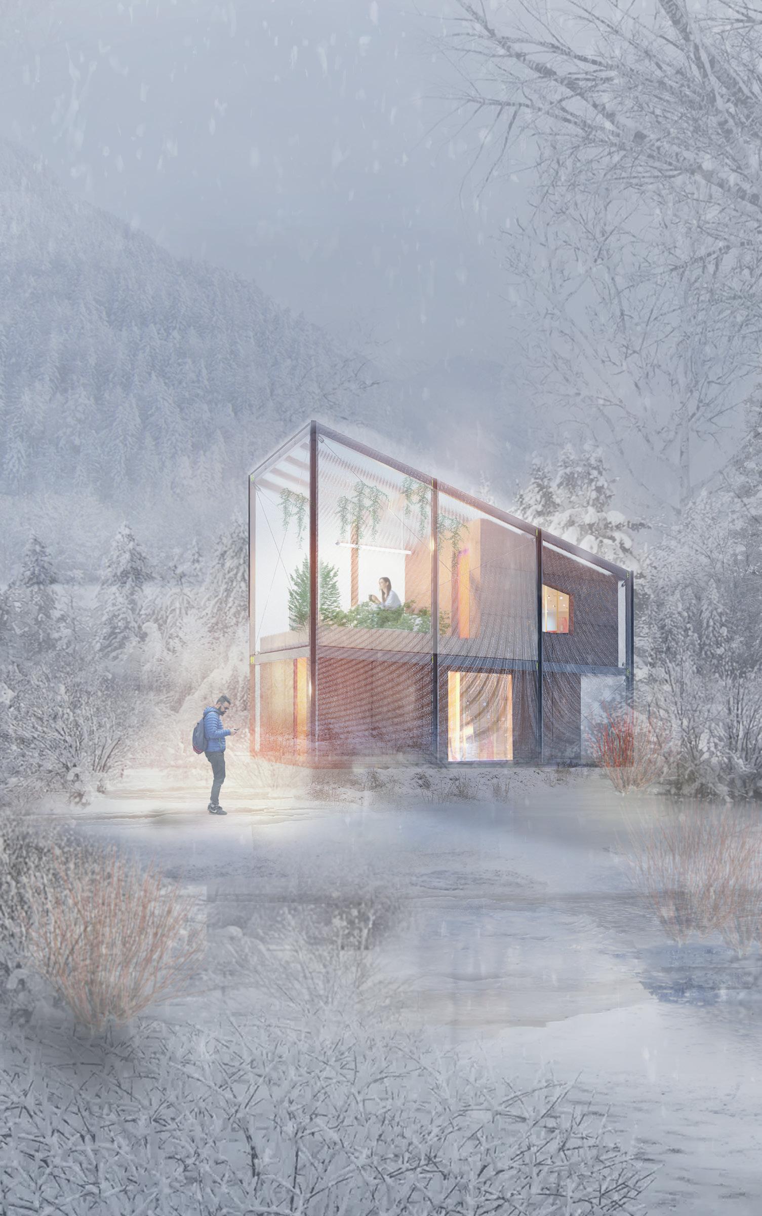
INTERIOR GREENHOUSE
The microhome features an enclosed indoor balcony, where lush greenery thrives within a protective polycarbonate shell, creating a greenhouse-like environment. This innovative design allows residents to experience a warm, nature-filled retreat while enjoying breathtaking Arctic views. The presence of greenery offers psychological benefits, countering the effects of long winter darkness and enhancing overall well-being.
THE LOFT
Designed for ultimate comfort and connection with nature, the bedroom offers an elevated, panoramic view of the Behchoko sky. With large openings that frame the spectacular aurora borealis, residents can experience the magic of the northern lights while lying in bed, making for an unforgettable and immersive living experience.
OPEN KITCHEN & LIVING ROOM
The entrance seamlessly blends into an open-concept living and kitchen space, fostering a sense of warmth and community. The wide, fluid circulation ensures ease of movement, while the spacious design enhances social interactions, making everyday experiences enjoyable and engaging for residents and visitors alike.
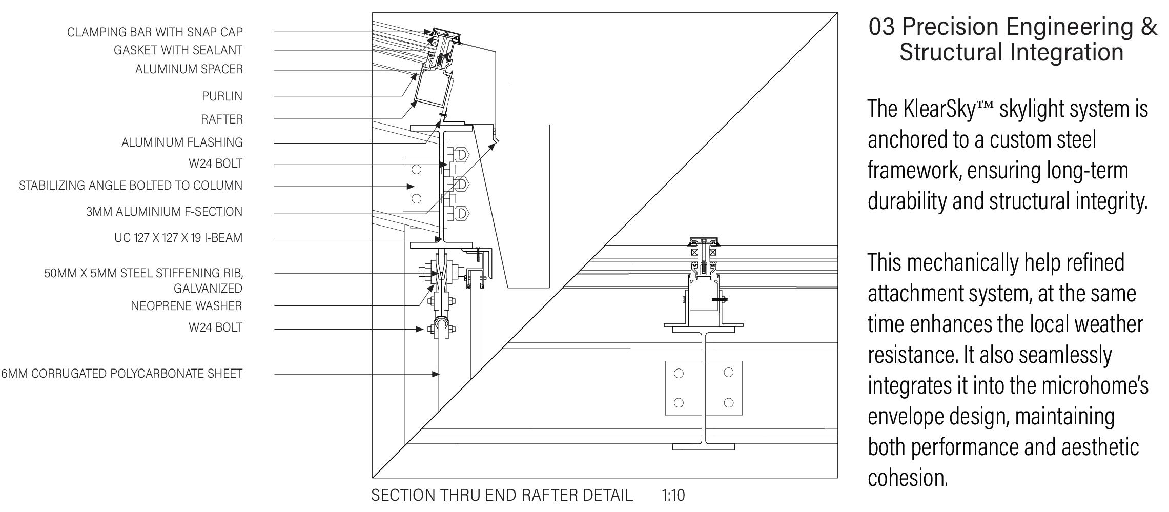
Polycarbonate Exterior Shell
Provides insulation while allowing natural light to penetrate
Timber Interior Core
Ensures warmth, structural stability, and a natural aesthetic
Double-Layered Glass Windows
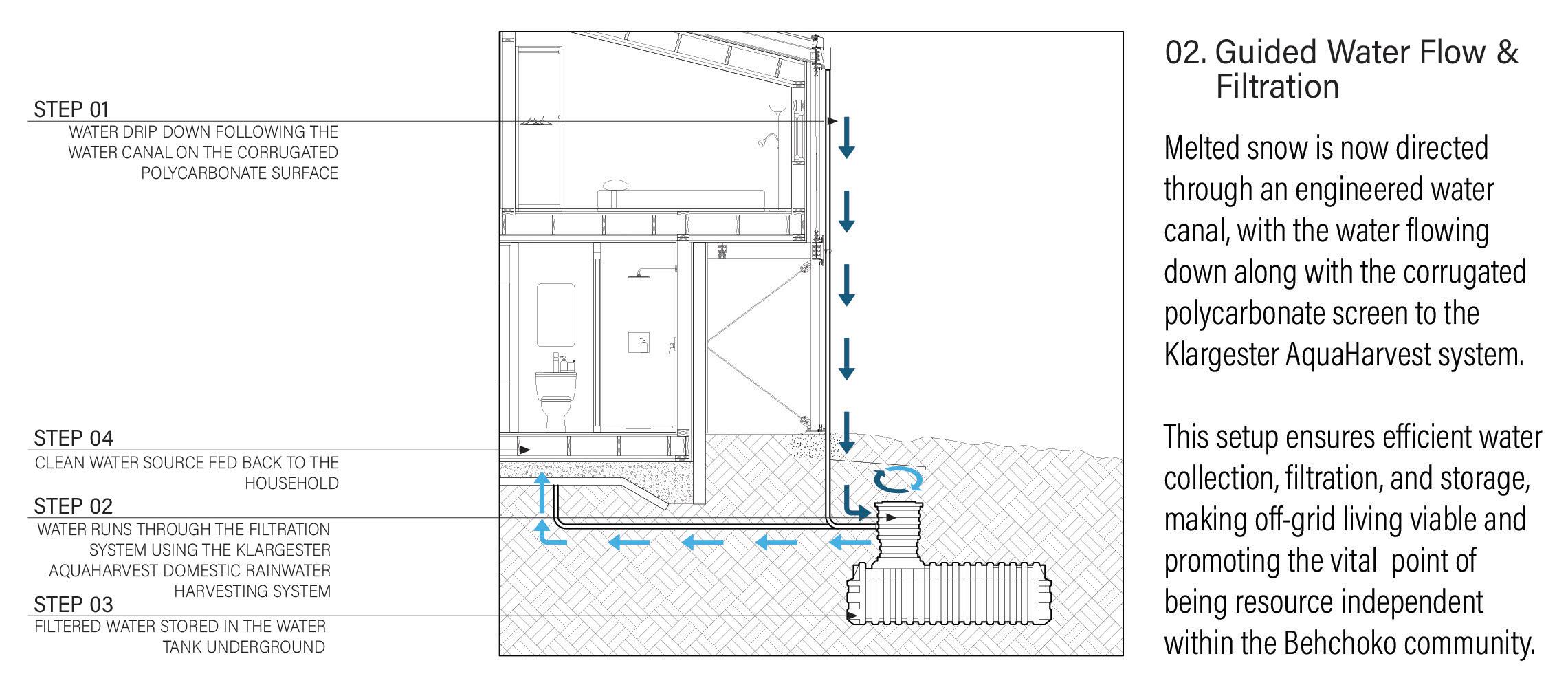
Reduces heat loss while integrating a heating system to melt rooftop snow for water collection
Kingspan Rainwater Harvesting Tanks
Captures and filters snowmelt, enhancing off-grid sustainability
High-Performance Insulation
Maintains thermal efficiency against extreme col
RESULT
This project serves as a visionary step toward sustainable tourism and housing in Northern Canada, demonstrating how thoughtful architecture can transform harsh environments into thriving, livable spaces.
- A fully conceptualized microhome that provides a sustainable, comfortable living experience in extreme Arctic conditions
- A design aligned with government strategies, boosting tourism while offering a viable long-term housing model
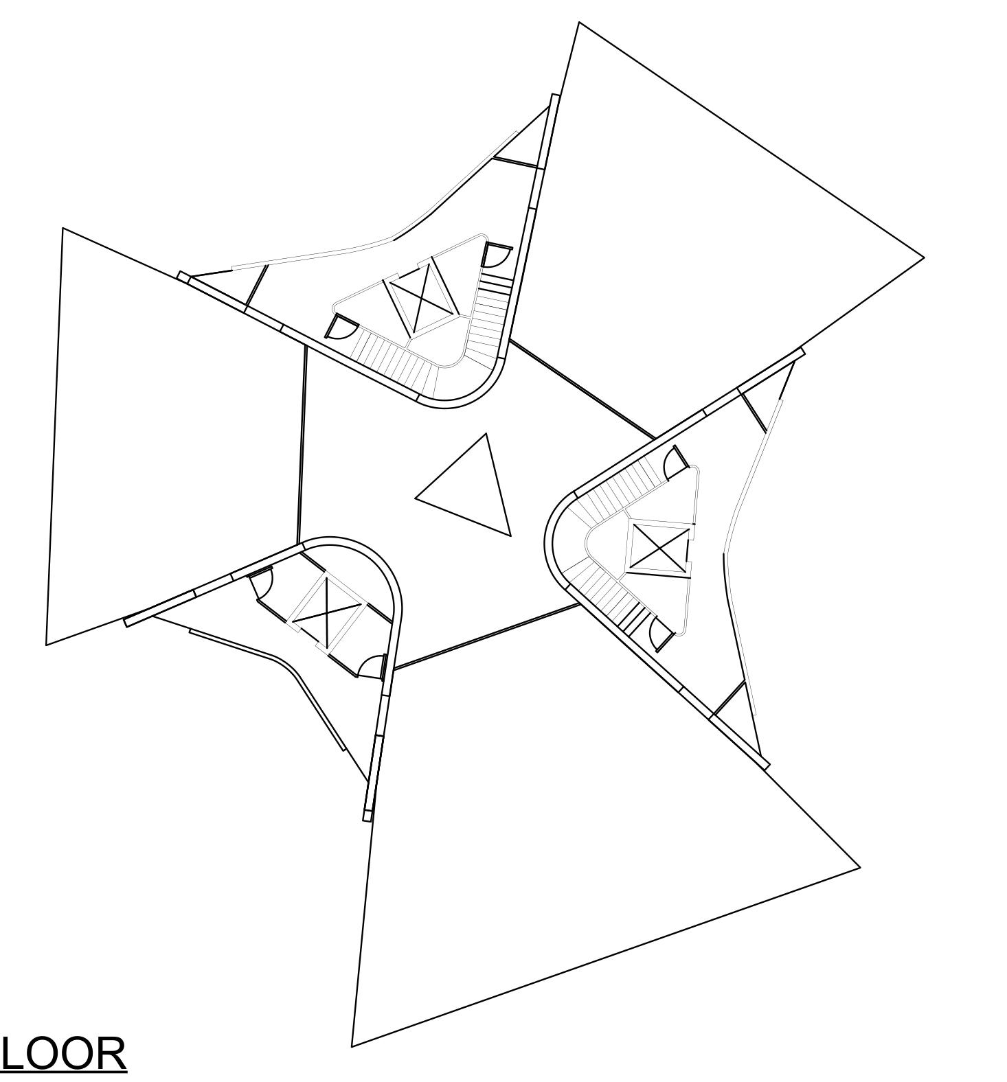
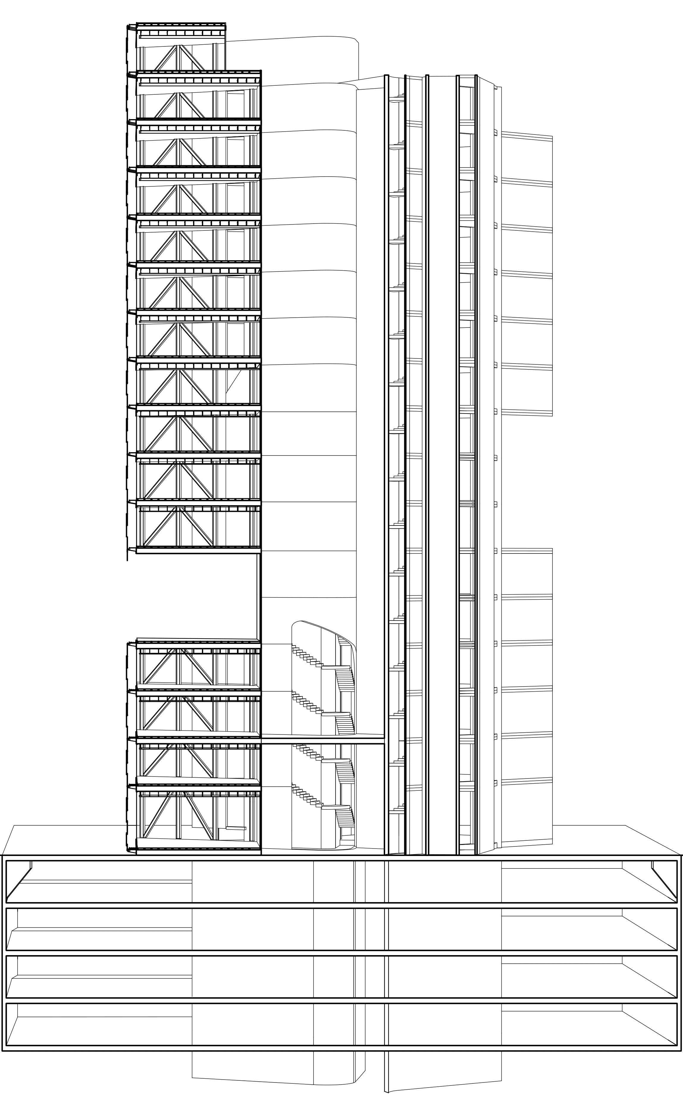
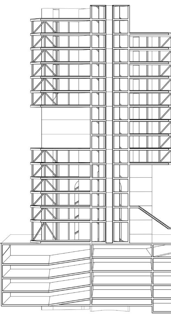
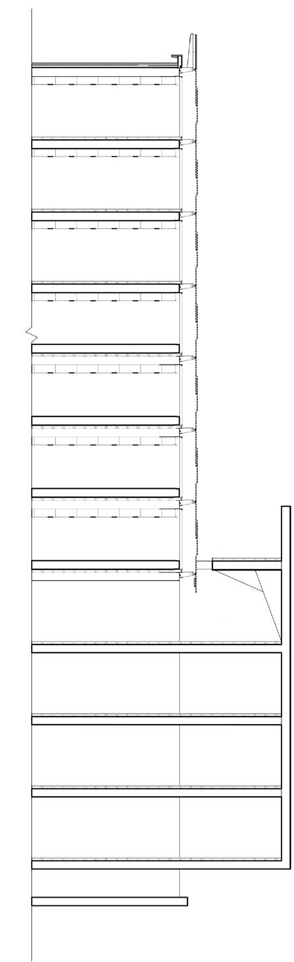
TORRE CUBE STRUCTURAL ANALYSIS
YEAR OF CONSTRUCTION: 2003-2005
ARCHITECT/DESIGNER: CARME PINOS
AREA: 4,800 M / 5,1667 FT
USE OF BUILDING: COMMERCIAL BUILDING - OFFICE
CONSTRUCTION TYPE: NEW CONSTRUCTION
BUILDING SITE: URBAN
LOCATION: BLVRD PUERTA DE HIERRO 5210, 45116 ZAPOPAN, JAL.
MATERIAL SYSTEM: HYBRID STEEL, WOOD AND STEEL, CONCRETE SYSTEMS
BUILDING'S ENVIRONMENTAL IMPACT AND MEASURES TAKEN TO REDUCE CARBON FOOTPRINT:
The Torres Cube’s design intent focuses on flexibility, sustainability, and environmental responsiveness. By centralizing structural support into three concrete cores, the building achieves expansive, column-free interiors. The design enhances functional efficiency while maintaining open spaces essential for modern office environments.
Environmental considerations are also a key part of this architecture, with passive cooling and natural ventilation forming key strategies. Voids between the cores facilitate airflow, contribute to thermal comfort and reduce reliance on mechanical cooling. Additionally, covered terraces provide shaded outdoor spaces, fostering occupant well-being and supporting sustainable design principles.
The Cube Tower presents notable structural challenges: first, designing a lateral force-resisting system for its irregular geometry in both plan and elevation, particularly given its location in a seismically active area. Second, creating column-free floor slabs to provide open, versatile interiors.
FLOOR PLAN SECTION A:A SCALE 1:200
RAIN LOAD ON ROOF
SUPERSTRUCTURE
WINDOW CONDITION
DEAD LOAD (SELF WEIGHT OF STRUCTURE, WEIGHT OF BUILDING ELEMENTS, FIXTURES AND EQUIPMENT ATTACHED)
BRACED FRAME SYSTEM CONSISTS OF THE DIAGONAL STEEL BRACES CREATES A STRONG FRAME THAT RESISTS THE SHEAR FORCE. BY CREATING A TRUSS-LIKE SYSTEM, HORIZONTAL FORCES ARE TRANSFERRED INTO AXIAL FORCES IN THE BRACES, WHICH THEN GETS ABSORBED, TRANSFERRED DOWN, AND DISTRIBUTED TO THE CORE, AND THEN THE FOUNDATION
OCCUPANCY LOAD, WEIGHT OF PEOPLE, FURNITURE, AND STORED MATERIAL
THE RIGID FRAME SYSTEM, WITH TENSION IN REPLACEMENT OF THE COLUMNS, HELPS RESISTS BENDING. THE CONNECTION BETWEEN THE BEAMS AND THE TENSION CORES ATTACHED TO THE RAINSCREENS CREATES BENDING MOMENTS RESISTING THE SWAY
THICK CONCRETE WALLS LOCATED AROUND THE CENTRAL CORE SERVED AS SHEAR WALLS CONVERTING THE HORIZONTAL FORCES INTO SHEAR STRESS, AND EVENTUALLY TRANSFERRING THEM DOWN THE FOUNDATION
SUBSTRUCTURE
LARGE CENTRAL CORE ALSO ABSORBS LATERAL FORCES, WHILE THE OUTRIGGER TRUSSES LINK THE CORE TO PERIMETER COLUMNS, KEEPING THE BUILDING UPRIGHT.
The Torres Cube’s design intent focuses on flexibility, sustainability, and environmental responsiveness. By centralizing structural support into three concrete cores, the building achieves expansive, column-free interiors. The design enhances functional efficiency while maintaining open spaces essential for modern office environments.
Environmental considerations are also a key part of this architecture, with passive cooling and natural ventilation forming key strategies. Voids between the cores facilitate airflow, contribute to thermal comfort and reduce reliance on mechanical cooling. Additionally, covered terraces provide shaded outdoor spaces, fostering occupant well-being and supporting sustainable design principles.
The Cube Tower presents notable structural challenges: first, designing a lateral force-resisting system for its irregular geometry in both plan and elevation, particularly given its location in a seismically active area. Second, creating column-free floor slabs to provide open, versatile interiors.
Despite the building's architectural complexity, the structural load path remains efficient.
In the parking levels, inclined floors optimize space by minimizing the need for ramps, preserving functional areas. The structural system in these levels consists of one-way post-tensioned slabs supported by perimeter walls, core walls, and vertical truss elements. These vertical trusses act as cantilevers, resisting constant bending moments.
The Cube Tower's design demonstrates an in-depth integration of architectural vision with advanced engineering solutions.
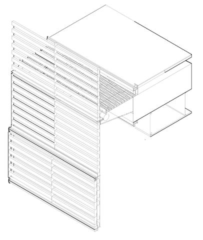
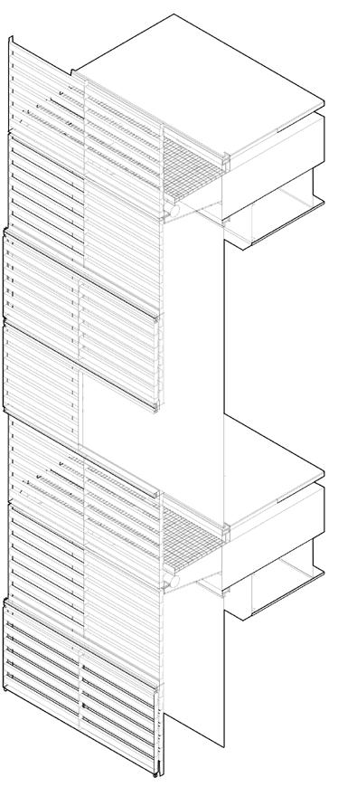
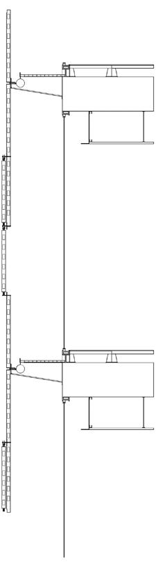
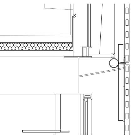
PASSIVE COOLING AND VENTILATION SYSTEM
SCALE 1:50
CROSS VENTILATION TAKING PLACE AS A RESULT OF THE PROFERRATED TIMBER PANEL
INTERNATIONAL GAP INBETWEEN THE RAINSCREEN AND THE EXTERIOR OF THE BUILDING ALLOWS FOR SUN SHADING
PERFORATION ALLOWING COOL AIR TO GET THROUGH THE PANEL
TIMBER PANEL SCREEN
TIMBER RAINSCREEN PANELS WITH PERFORATION ALLOWING FOR CROSS VENTILLATION TO HAPPEN, WHILST PROVIDING SHADE TO THE SPACES. THE RAINSCREEN PANELS ALSO PROVIDES HEAT PROTECTION FROM THE SUN, DUE TO THE ARID CLIMATE CONDITION OF GUANDALAJARA
THE CONCRETE FLOOR SLAB PROVIDED LATERAL LOAD RESISTANCE AND STABILITY TO THE BUILDING
THE STEEL FLANGES CONNECTS THE RAINSCREEN PANEL TO THE FLOOR SLABS, CREATING A TENSION SYSTEM, HOLDING THE WALKWAY
STAGE I - SCALE 1:1000
SITE DUG OUT AND CONTIGUOUS PILED WALLS ARE INSTALLED, AND IT IS USED AS THE FOUNDATION. PAD FOUNDATIONS FOR THE THREE CORES ARE CASTED IN SITU
STAGE IV - SCALE 1:1000
STEEL BEAMS FORMING TRAPEZOID SHAPES ARE FIXED ONTO THE CONCRETE CORES THROUGH LONG NAILS AND SCREWS.
STAGE II - SCALE 1:1000
RIGID STEEL GRID CONSTRUCTION TO CREATE AS LITTLE GROUND IMPACT AS POSSIBLE
STAGE V - SCALE 1:1000
SERVICES LIKE WATER, ELECTRICITY ARE ADDED TO THE COMPLETED LOWER LEVELS FOR BASIC USE, AND THEN TO THE HIGHER LEVELS
STAGE III - SCALE 1:1000
SERVICE CONCRETE CORES ARE CAST ON SITE AS FOUNDATION HERE.
STAGE VI - SCALE 1:1000
TENSION STRUCTURE ARE INSTALLED TO ATTACH THE RAINSCREEN PANELS TO THE BUILDING
The Cube Tower’s innovative material system combines concrete, steel, and wood to achieve a balance between structural performance, environmental responsiveness, and functional adaptability. The primary system, consisting of curved concrete cores, provides lateral load resistance and seismic stability in a region of high seismic risk. These cores serve as the central support for the tower, transmitting loads to three mat foundations and enabling column-free interiors. This design supports large, adaptable office spaces and unobstructed parking layouts.
The secondary system features steel trusses that transfer loads from the floor slabs to the cores. These trusses work in tandem with posttensioned slabs, allowing for long spans that maintain open floor plans. The hybrid use of concrete for compressive strength and steel for tensile efficiency ensures a lightweight yet robust structure, optimizing material usage while achieving flexibility in spatial design.
Wooden louvers on the façade constitute the tertiary system, contributing to passive cooling and solar shading. These elements reduce heat gain and energy consumption while complementing the building’s aesthetic integration within the urban and tropical context. The louvers, combined with the voids between the cores and covered terraces, enhance ventilation and thermal comfort, aligning with the project’s sustainable goals.
The material system of the Torres Cube exemplifies a “parts-to-whole” system, where each component—concrete cores, steel trusses, and wooden louvers—plays a crucial role in supporting the building’s structural integrity, environmental performance, and user-centered functionality. The careful coordination of these elements reflects a thoughtful response to climate conditions, seismic challenges, and the demands of modern highrise design.
ADVANTAGES OF HYBRID MATERIALITY (CONCRETE, STEEL, WOOD)
Efficiency and Aesthetics: This system supports open and functional spaces, enhances energy efficiency with natural lighting and ventilation, and ensures a striking visual identity.
Sustainability: Using wood and efficient structural materials minimizes environmental impact, aligning with sustainable design principles. Seismic Performance: The integration of these materials optimizes the building's ability to withstand seismic forces while maintaining flexibility in design and functionality.
STEEL BEAM STRUCTURE
SCALE 1:200
CONCRETE:
The three central concrete cores act as the primary structural system, providing strength and stability while resisting both vertical and lateral loads. This system reduces the need for internal columns, creating open, flexible spaces ideal for offices and parking areas. Concrete's high durability also ensures long-term performance and resistance to seismic activity, critical for a high-rise in an earthquake-prone area.
STEEL:
Steel is used in the cantilevered beams and trusses, offering exceptional tensile strength and facilitating long spans without support. This allows for column-free floor slabs and efficient load distribution from the office wings to the central cores. Its adaptability supports the building’s complex geometry while minimizing material usage.
WOOD LOUVERS:
Wooden louvers serve as the outermost layer of the façade, providing a lightweight and sustainable shading system. They regulate natural light and ventilation, reducing solar heat gain and energy demand while contributing to the building’s aesthetic appeal and warmth.
ADVANTAGES OF HYBRID MATERIALITY (WOOD, CONCRETE, STEEL)
Efficiency and Aesthetics: This system supports open and functional spaces, enhances energy efficiency with natural lighting and ventilation, and ensures a striking visual identity.
Sustainability: Using wood and efficient structural materials minimizes environmental impact, aligning with sustainable design principles. Seismic Performance: The integration of these materials optimizes the building's ability to withstand seismic forces while maintaining flexibility in design and functionality.
SCALE 1:200
STEEL BEAM AND HOLLOW CONCRETE SLAB FLOOR PLAN
SCALE 1:200
GRAVEL
TWO LAYER BITUMINOUS SEAL
40MM THERMAL INSULATION
420MM REINFORCED CONCRETE
40MM THERMAL INSULATION
12.5MM PLASTERBOARD SUSPENDED SOFTFIT
50.8/50.8/4.8MM STEEL ANGLE
6MM FLOAT GLASS IN ALUMINUM FRAME
120MM HOLLOW FLOOR SYSTEM
GALVANISED STEEL GRATING
200/270/6MM STEEL ANCHOR PLATE
40MM THERMAL INSULATION
102.9MM STEEL TUBE
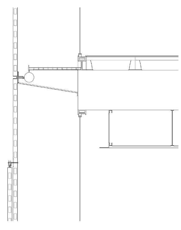
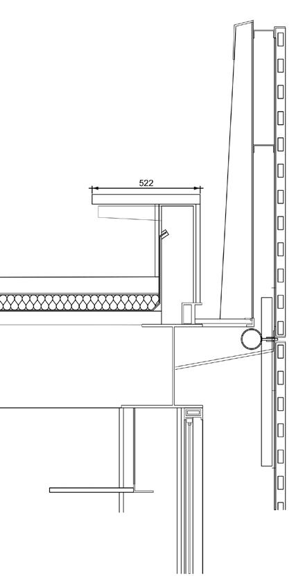
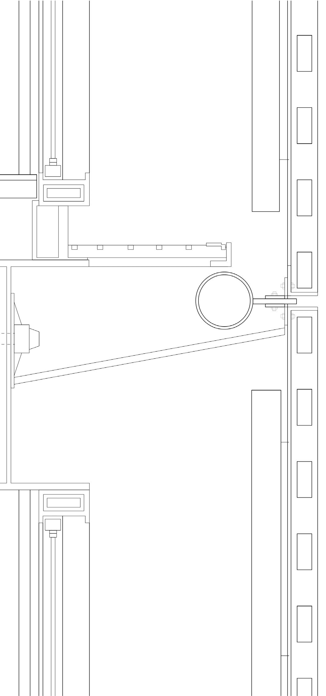
WINDOW AND RAINSCREEN PANEL DETAIL
SCALE 1:20
GUIDE TRACK
6MM FLOAT GLASS ALUMINUM WINDOW FRAME
120MM HOLLOW FLOOR SYSTEM
400MM CONCRETE SLAB
102.9MM STEEL TUBE
POST-TENSION CABLE END
STEEL BRACKET WITH 5MM WEB FLANGE
STEEL EDGE BEAM
48.3/5.54MM TUBULAR STEEL BRACING
WINDOW AND TIMBER
SCALE 1:20
25/60 MM HEAT-TREATED PINE STRIP
TWO LAYER BITUMINOUS SEAL
40MM THERMAL INSULATION
48.3/5/54MM TUBULAR STEEL BRACING
12.5MM PLASTERBOARD SUSPENDED SOFFIT
ALUMINUM WINDOW FRAME ATTACKED TO THE CONCRETE FLOOR SLAB, TRANSFERING THE LOADS DOWN
6MM WELDED STEEL FLATS
GUIDE TRACK AND ROLLERS FOR SLIDING SCREEN
6MM FLOAT GLASS IN ALUMNUM FRAME
ALUMINUM WINDOW FRAME HEALPING THE TRANSFER OF LOADS TO THE CONCRETE FLOOR SLAB
WINDOW SECTION DETAIL
SCALE 1:50
38/38/4.8MM STEEL ANGLE
RAINSCREEN SECTION DETAIL
PARAPET DETAIL WITH ROOF PLATE
SCALE 1:20
BEAM TO ROOF DETAIL
SCALE 1:20
GROUND CONDITION
SCALE 1:20
50.8/50.8/4.8MM STEEL ANGLE
CHANNEL 101.2MM
28/60MM HEAT-TREATED PINE STRIP
CHANNEL 101.2MM
40MM STONE SLAB
STEEL PLATE
LAYER OF GRAVEL
STEEL GRATING
TWO LAYERS OF BITUMINOUS SEAL
102.9MM STEEL TUBE
50.8/50.8/4.8MM STEEL ANGLE
40MM THERMAL INSULATION
40MM THERMAL INSULATION
28/60MM HEAT-TREATED PINE STRIP
HOLLOW FLOOR SYSTEM
STEEL GRATING-SERVICE WALKWAY
400MM CONCRETE SLAB
EDGE STEEL BEAM
6MM FLOAT GLASS WINDOW
TWO LAYERS BITUMINOUS SEAL
CONCRETE TOPPING
50.8/50.8/4.8MM STEEL ANGLE
102.9MM STEEL TUBE
EDGE BEAM
WINDOW SILL
400MM CONCRETE SLAB
GRASS
HUMUS
BLOCK
STEEL BRACKET WITH 5MM WEB FLANGE DRAIN
MORTAR
GEOCOMPOST WATERPROOFING
REINFORCED
WALL SECTION
SCALE 1:200
STEEL GRID
28/60MM HEAT-TREATED PINE STRIP BOLT
50.8/50.8/4.8MM STEEL ANGLE FALT BAR
102.9MM STEEL TUBE
FALT BAR
POST-TENSION CABLE END BOLT
48.3/5.54MM TUBULAR STEEL BRACING
EDGE BEAM
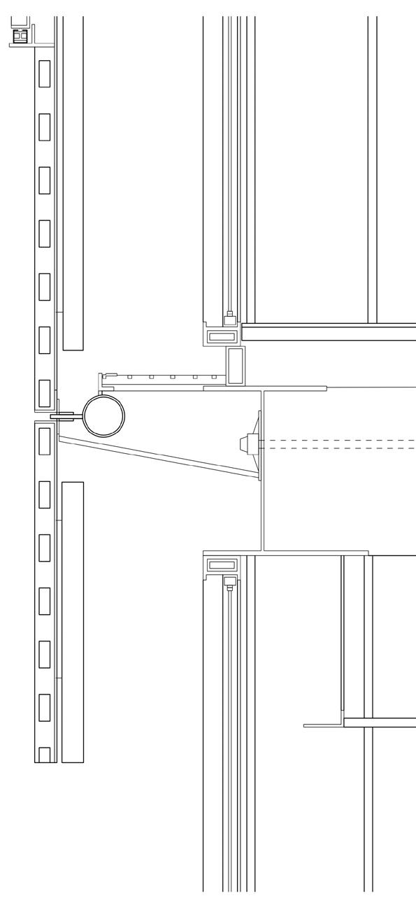
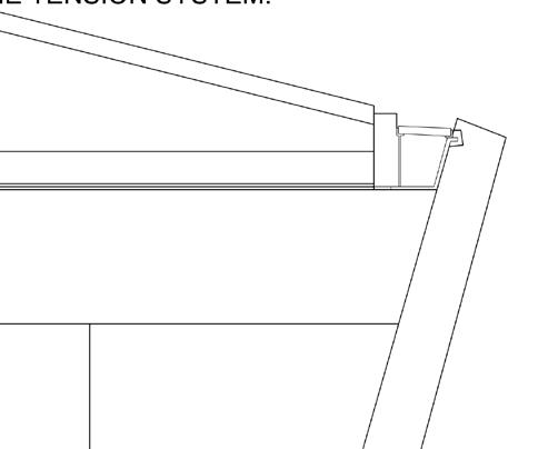
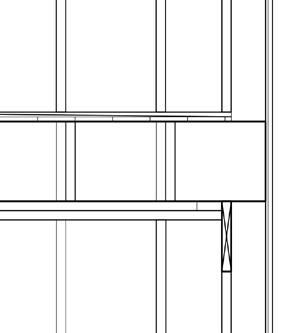
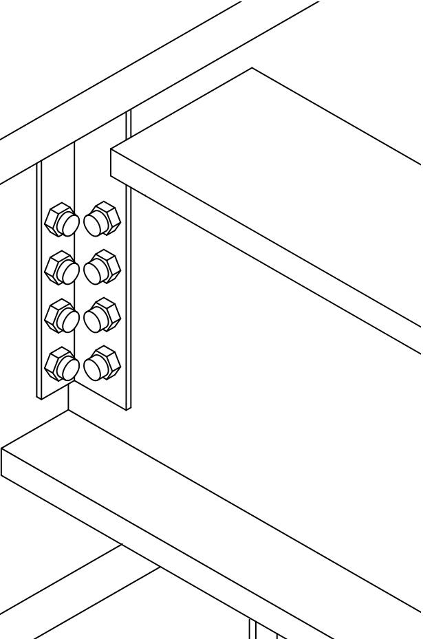
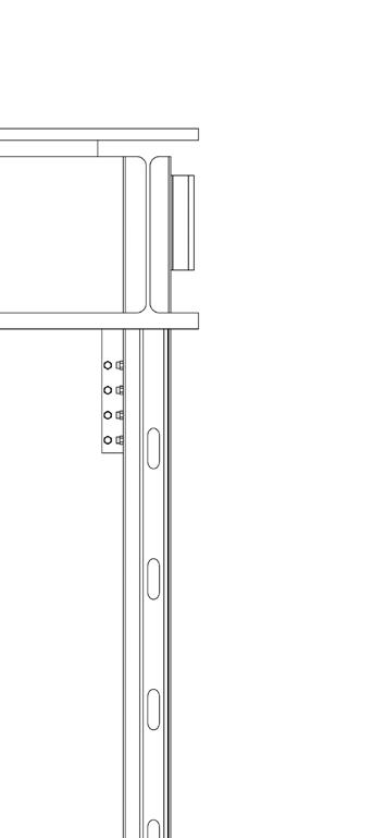
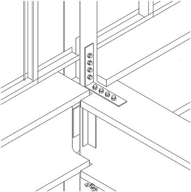
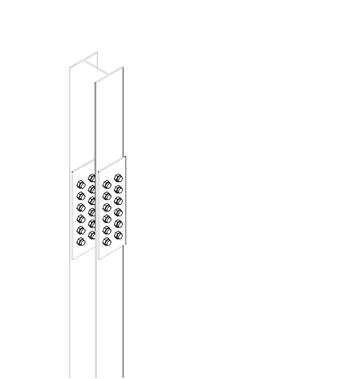
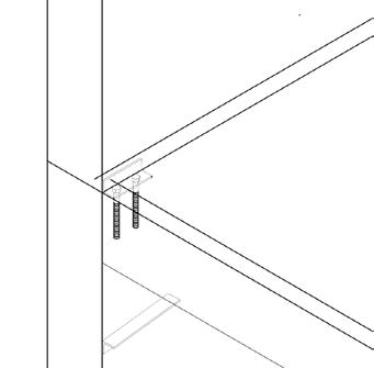
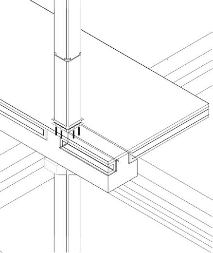
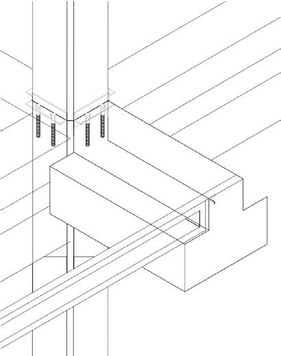
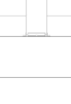
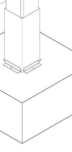
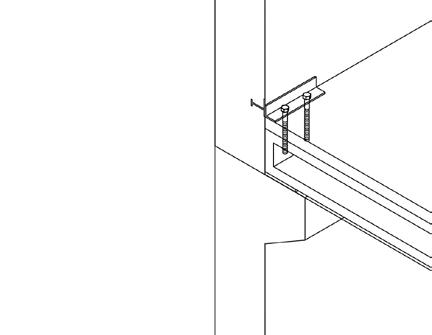
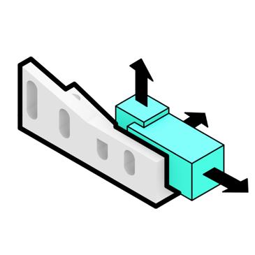
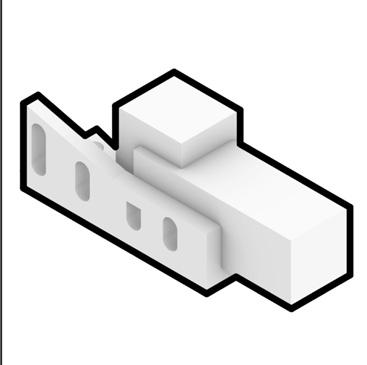
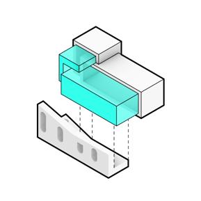
Torre cube is a column free building. The load is supported by curved walls of concrete cores and steel wall beams cantilevered from the walls. In replacement of the column detail, this diagram shows a blow up connection detail for the tension system.
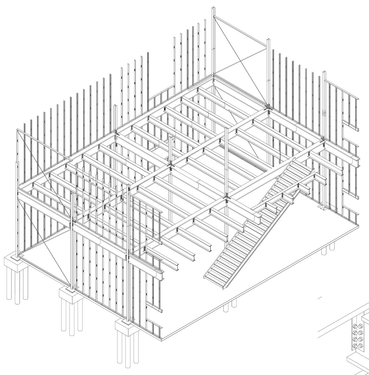
30' X 40' FOUR DIFFERENT STRUCTURE CONSTRUCTION DETAILS
Buildings are constructed using a variety of structural materials and systems, each with unique characteristics that cater to specific design and functional requirements.
METHOD OF
CONSTRUCTION
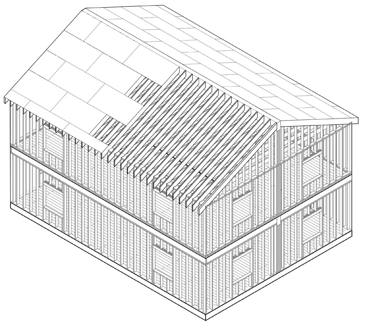
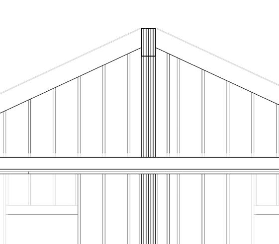
LIGHT FRAME WOOD CONSTRUCTION
ADVANTAGES AND DISADVANTAGES OF CONSTRUCTION
Platform framing and balloon framing are two predominant methods in timber construction, each with distinct advantages and disadvantages.
Platform framing, widely used today, involves constructing floors one at a time, providing stable working surfaces. Its advantages include increased safety during construction, energy efficiency due to better insulation between floors, and compatibility with modular building techniques. However, its discontinuous studs create potential weak points for vertical load transfer, making it less suitable for taller structures.
Balloon framing, common in the 19th century, uses continuous studs running from foundation to roof, allowing for unbroken vertical load paths. This method is advantageous for tall buildings and minimizes settling issues. However, it requires longer lumber, making it less cost-effective and challenging to source. Additionally, its open stud cavities increase fire risk as flames can spread quickly through the walls.
Francis Ching’s Building Construction Illustrated (2021) provides comprehensive insights into these framing techniques.
LATERAL LOAD ANALYSIS DIAGRAM
SCALE 1/8"=1'-0"
LOAD TRNASFERRED THROUGH RIDGE RAFTERS
BUILDING ENVELOPE
2'X4' SHEATHING
2'X12' TIMBER, ROOF BEAM
2'X10' CEILING JOIST
2'X10' RIDGE RAFTER
OCCUPANCY LOAD FROM
WEIGHT OF PEOPLE, FURNITURE
2 LAYERS OF PLYWOOD SUBLOOR
2'X6' TIMBER, DOUBLE TOP PLATE
2'X6' TIMBER, DOUBLE TOP PLATE
2 LAYERS OF PLYWOOD SUBLOOR
2X6 TIMBER (ACTUALL SIZE 1-1/2" X 5-1/2")
SCALE 1"=1'-0"
CHANNEL 101.2MM
DOOR OPENNING
SCALE 1/2"=1'-0"
TWOP CRIPPLE STUD
2X10 HEADER KING STUD
JACK STUD
DOOR OPENNING
2X6 STUD
SCALE 1/2"=1'-0"
2 LAYERS 4'X8' PLYWOOD SUBFLOORING
2X6 TIMBER HEADER
TRIMMER STUD KING STUD
THICKENED EDGE FOUNDATION EVENTUALLY TRANSFERS THE LATERAL LOAD DOWN INTO THE GROUND
BEAM AT SECOND FLOOR PLATE
SCALE 1/4"=1'-0"
2X10 TIMBER RIDGE RAFTER 2X6 TIMBER, DOUBLE TOP PLATE
ROOF RAFTERS WALL STUD
SCALE 1/2"=1'-0"
BEAM AT ROOF DETAIL
SCALE 1/4"=1'-0"
JOINT HANGER 4X8 PLYWOOD, ROOF SHEATHING
2X6 DOUBLE HEADER
SCALE 1/2"=1'-0"
FOUNDATION BOLT
CONCRETE SLAB
BOLT CONNECITON
SCALE 1/2"=1'-0"
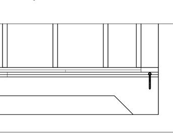
SOLE PLATE
FLOOR SHEATHING
FLOOR JOIST
DOUBLE END JOIST
DOUBLE TOP PLATE
INDEPENDENT STUD, NOT CONNECTED FROM 2F
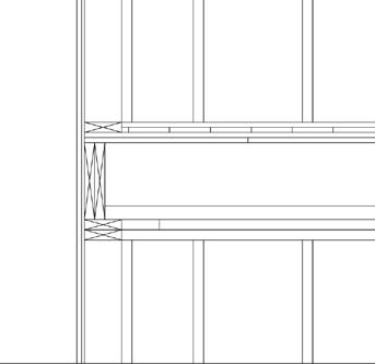
JOINT HANGER BALLOON FRAMING
SCALE 1/2"=1'-0"
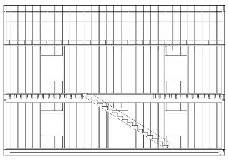
LONGITUDINAL SECTION
SCALE 1/8"=1'-0"
SUBFLOOR
SUBFLOOR
CONCEALED SPACE IN WALL FRAMING
LEDGER STUD
FIRST FLOOR JOIST
PLATFORM FRAMING
SCALE 1/2"=1'-0"
DECKING
JOIST HANGER BLOCKING
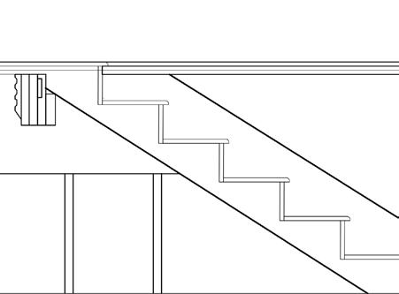
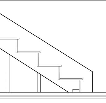
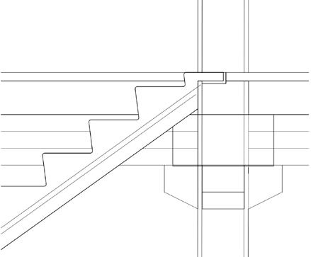
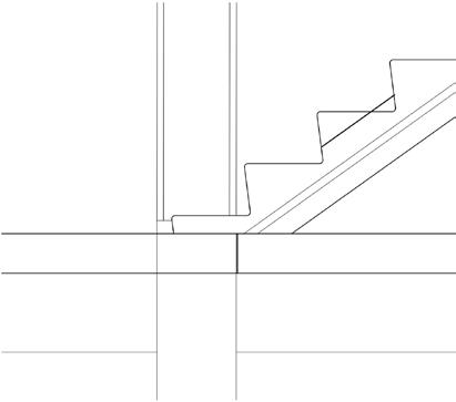
RISER STRINGER TREADER
SCALE 1/2"=1'-0"
CARRIAGE KICK PLATE
DECKING
RISER
STAIRCASE 1F
CHAMFER EDGES OF PLYWOOD TREADS FOR CARPETING
SCALE 1/2"=1'-0"
30' X 40' FOUR DIFFERENT STRUCTURE CONSTRUCTION DETAILS
Buildings are constructed using a variety of structural materials and systems, each with unique characteristics that cater to specific design and functional requirements.
METHOD OF CONSTRUCTION STEEL CONSTRUCTION
Steel’s strength and load-bearing capabilities makes the steel construction a popular choice in building structures, yet it is very sensitive to temperature increases, such as fire. According to Francis Ching’s Building Construction Illustrated, When "used in buildings requiring fire-resistive construction, structural steel must be coated, covered, or enclosed with fire-resistant material", and if not, it can lead to rapid failure in fire conditions (Ching, p. 12.08). In addition, because steel is "normally subject to corrosion, steel must be painted, galvanized, or chemically treated for protection against oxidation" (Ching, p12.08) . As noted by Ching, "Structural steel may be left exposed in unprotected noncombustible construction, but because steel can lose strength rapidly in a fire, fire-rated assemblies or coatings are required to qualify as fire-resistive construction." These are the disadvantages of Steel construction.
Deplazes also notes that steel's thermal conductivity leads to the fact that steel structures needs special treatment. For example, "metal windows have a high thermal conductivity and so the frame sections must include a thermal break." (Deplazes, p. 183). This vulnerability necessitates the application of fireproofing measures, such as intumescent coatings or encasing steel in fire-resistant materials, which can increase costs and add to construction time.
W6X15 COLUMN
8" BUILDING ENVELOPE
STIFFNER ANGLE
W24X104 GIRDER
LIGHT GAUGE STEEL STUD 24" O.C.
W6X15 COLUMN
STIFFENER ANGLE
EXPANSION BOLT
2" CONCRETE FILLED METAL TREADS
STRINGER RISER C-STUD
W6X15 COLUMN
EXPANSION JOINT foundation 17" O.C. CONCRETE SLAB
STIFFENER ANGLE W24X104 GIRDER BOTTOM U-TRACK
JOIST TO GIRDER SCALE 1"=1'-0"
W24X104 GIRDER
FLOOR DECKING
SCALE 1/2"=1'-0"
COLUMN WALL SCALE 1/4"=1'-0"
FOUNDATION DETAIL
SCALE 1/8"=1'-0"
W24X104 GIRDER
STIFFENER ANGLE
COLUMN WALL
SCALE 1/2"=1'-0"
W6X15 COLUMN TO PAND BOTTOM PLAGES TO PAND BOTTOM PLAGES WELDED TO COLUMN WELDED TO BEAM WEB
STIFFENER PLATES WELDED TO COLUMN DOUBLE C-STUD W6X15 COLUMN
COLUMN TO BEAM MOMENT COLUMN TO BEAM SHEAR COLUMN TO COLUMN SCALE 1/2"=1'-0" SCALE 1/2"=1'-0"
SCALE 1/4"=1'-0"
SCALE 1/2"=1'-0"
LONG SECTION
SCALE 1/8"=1'-0"
W18X50 BEAM
CONCRETE FILLED METAL PAN TREADS
STIFFENER GIRDER
W24X104 GIRDER
SCALE 1/2"=1'-0"
SCALE 1/16"=1'-0"
30' X 40' FOUR DIFFERENT STRUCTURE CONSTRUCTION DETAILS
Buildings are constructed using a variety of structural materials and systems, each with unique characteristics that cater to specific design and functional requirements.
METHOD OF CONSTRUCTION
CONCRETE CONSTRUCTION
Concrete provides notable fire safety benefits due to its non-combustibility and effectiveness as a fire barrier, helping to ‘limit the spread of fire’ and safeguard building occupants (Ching, Building Construction Illustrated, 4.11). Its structural integrity largely withstands high temperatures, supporting safe evacuation routes. The material’s slower heat absorption rate further protects interiors by delaying fire progression. However, certain limitations exist; under extreme heat, concrete, particularly high-strength types, may undergo ‘spalling,’ or surface flaking, which can compromise structural integrity (Allen and Iano, The Architect’s Studio Companion, p. 109). Fire resistance in concrete depends on factors like adequate reinforcement and slab thickness, as well as accommodating thermal expansion, which can lead to cracking if unaccounted for. Additionally, water absorption during firefighting may diminish concrete's fire resistance. Despite these challenges, concrete remains a preferred choice for fire-resistant construction, especially when combined with ‘fire compartmentalization methods’ that further restrict flame spread (Ching, 4.10). Strategic mix design and reinforcement placement can further optimize its fire performance, making it a resilient solution for firesafe building designs.
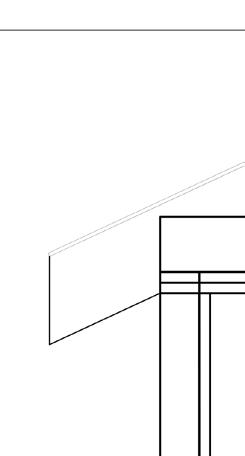
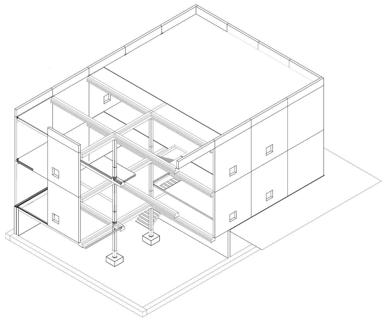
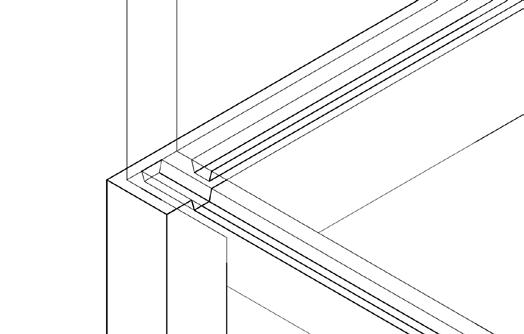
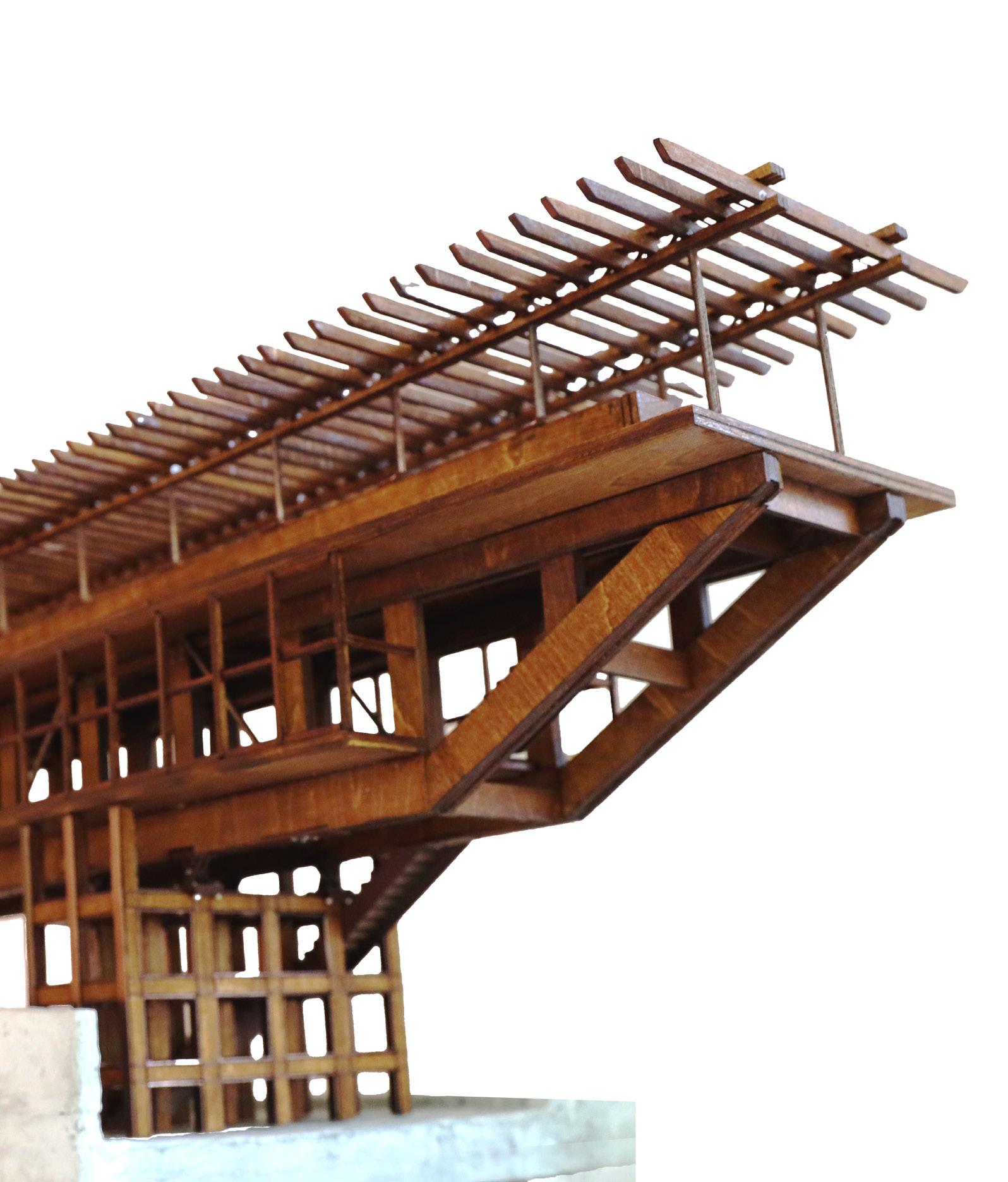
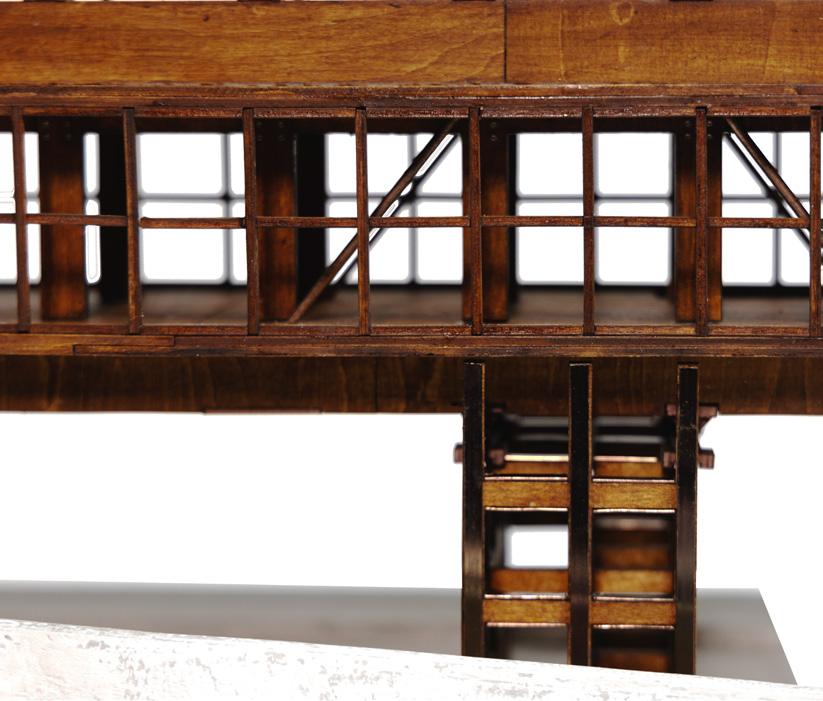
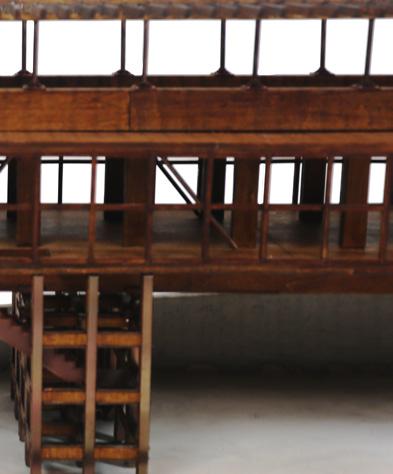
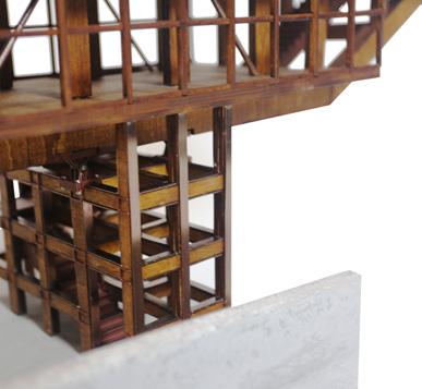
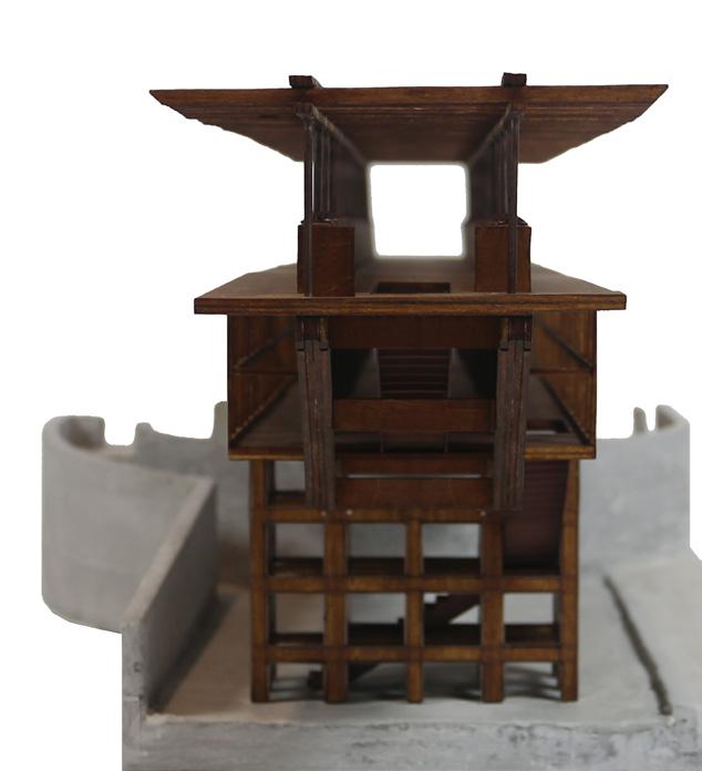
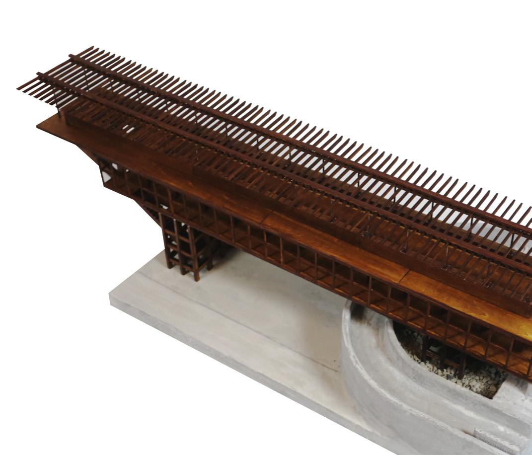
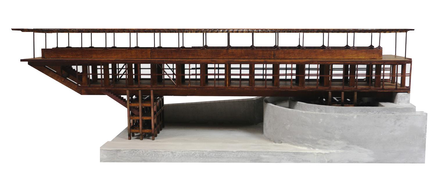
This project centers on the creation of a precise, hand-crafted model to uncover and understand the intricate structural desing of the zenbo seieni wellness centre. By deconstructing and replacing its kdy structural elements, the model acts as a tool for exploring the innovative techniques embedded in the original architecture.
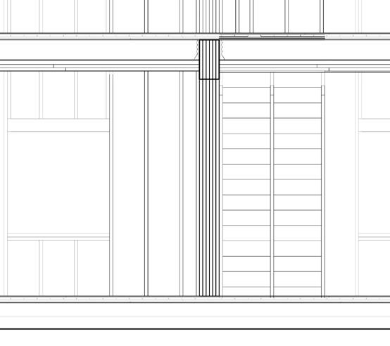
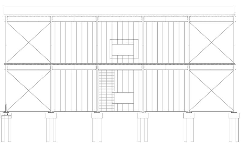
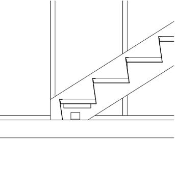
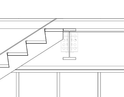
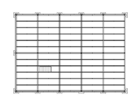
TIMBER FRAME STRUCTURE SCALE 1:50
ELEVATION VIEW
SCALE 1:50
STRUCTURE DETAIL
SCALE 1:50
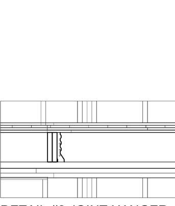
JOIINTS DETAIL
SCALE 1:50
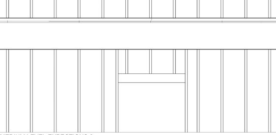
SIZE VIEW
SCALE 1:50
ISOMETRIC VIEW
SCALE 1:50
ELEVATION VIEW
SCALE 1:50
BANK OF LONDON, BUENOS AIRES, ARGENTINA
OTHER WORKS FORMS RECONSTRUCTION
In 1959 a contest was held for a project at the invitation of the Headquarters of the Bank of London and South America. The land was located on a street corner in downtown Buenos Aires. The winning design was submitted by the team by Clorindo Testa. This project is one of the most original, bold, and far-reaching of the international architecture of the 60s, the signature of the brutalism architecture style. In this project, by converting this classic brutalism column into a new building to show different possibilities by just a simple move.