Hello, I am Dambar.
Having been born in a small village in the Gorkha district of Nepal, my journey in the field of architecture has been truly exceptional and fulfilling. After completing my high school education in Chitwan, a town located approximately 80 kilometres away from my village, I dreamed of developing a career in the field of architecture. Despite this dream, in 2008, I chose to follow in the footsteps of my ancestors and joined the British army, where I served with dedication for seven years, enjoying the experiences of traveling around the world and making “band of brothers”.
Despite the joy I found in the armed forces, my passion for architecture never diminished. Driven to achieve my childhood dream, I made the pivotal decision to depart from the military and continued my academic pursuit. Earning a BA (Hons) in Architecture from the University of Kent, I commenced my professional journey as a Part 1 architectural assistant at Richard Reid and Associates (RRA). After gaining two years of invaluable experience, I decided to continue my higher education, enrolling once more at the University of Kent for a Master of Architecture degree. Recently graduated, I currently hold the position of CAD technician at Butler Harwell Ltd.

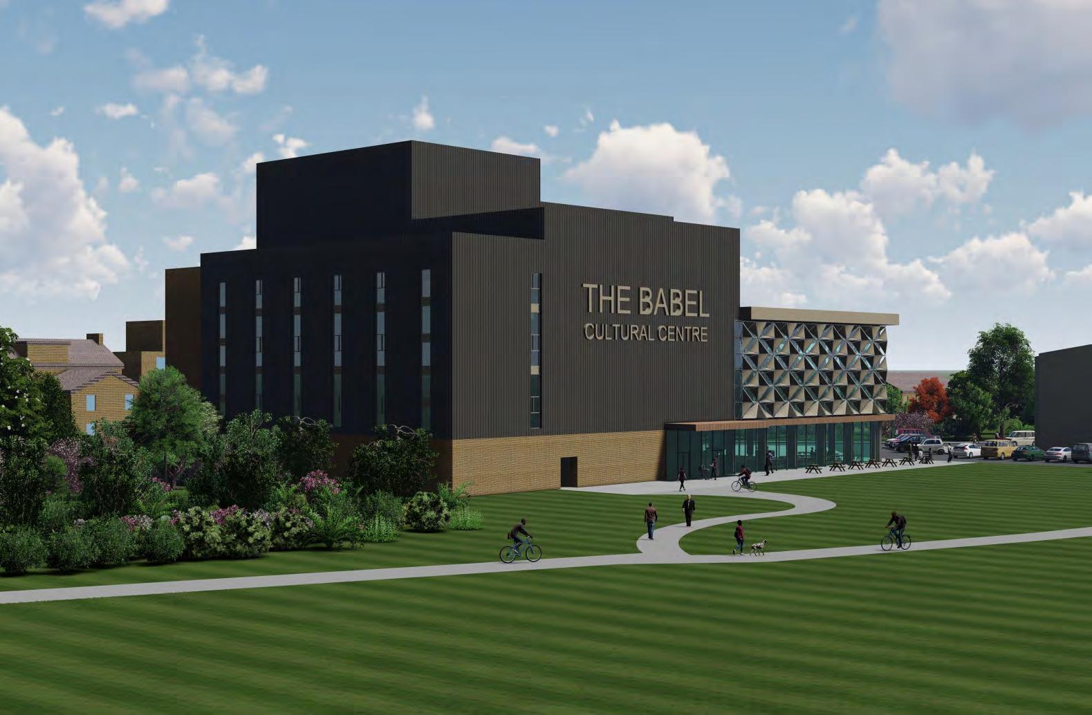
The Babel Cultural Centre

The site is situated in the borough of Southwark, which is known for its diverse community. The aim of this project is to bring these communities together and address the challenges posed by cultural barriers within the Borough. Unification of Cultures is a complex concept that encompasses the coming together of diverse communities, traditions, and perspectives. It involves fostering understanding, respect, and appreciation for different cultures while seeking common ground and shared values.
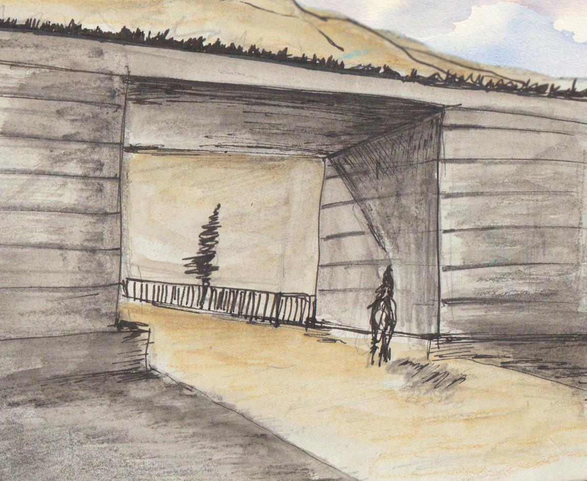
The central idea behind the building’s design is rooted in the contrasting theory of an ancient biblical tale known as “The Tower of Babel.” According to the story, a united human race speaking a single language migrates in the land of Shinar. There, they decide to construct a city and a tower that reaches the heavens. Observing their ambitious project, The God confounds their speech so that they can no longer communicate with each other, leading to their dispersal across the world.
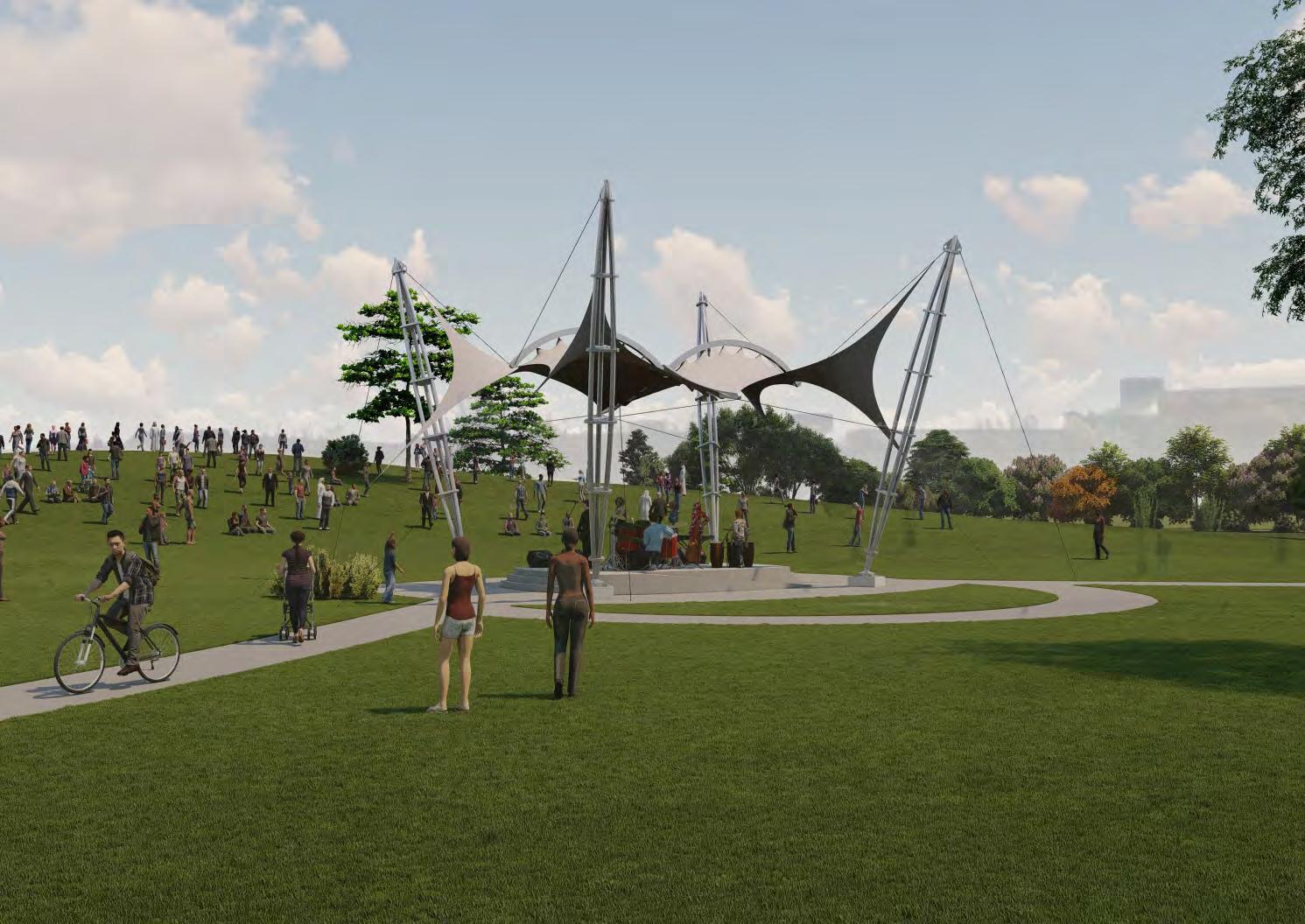
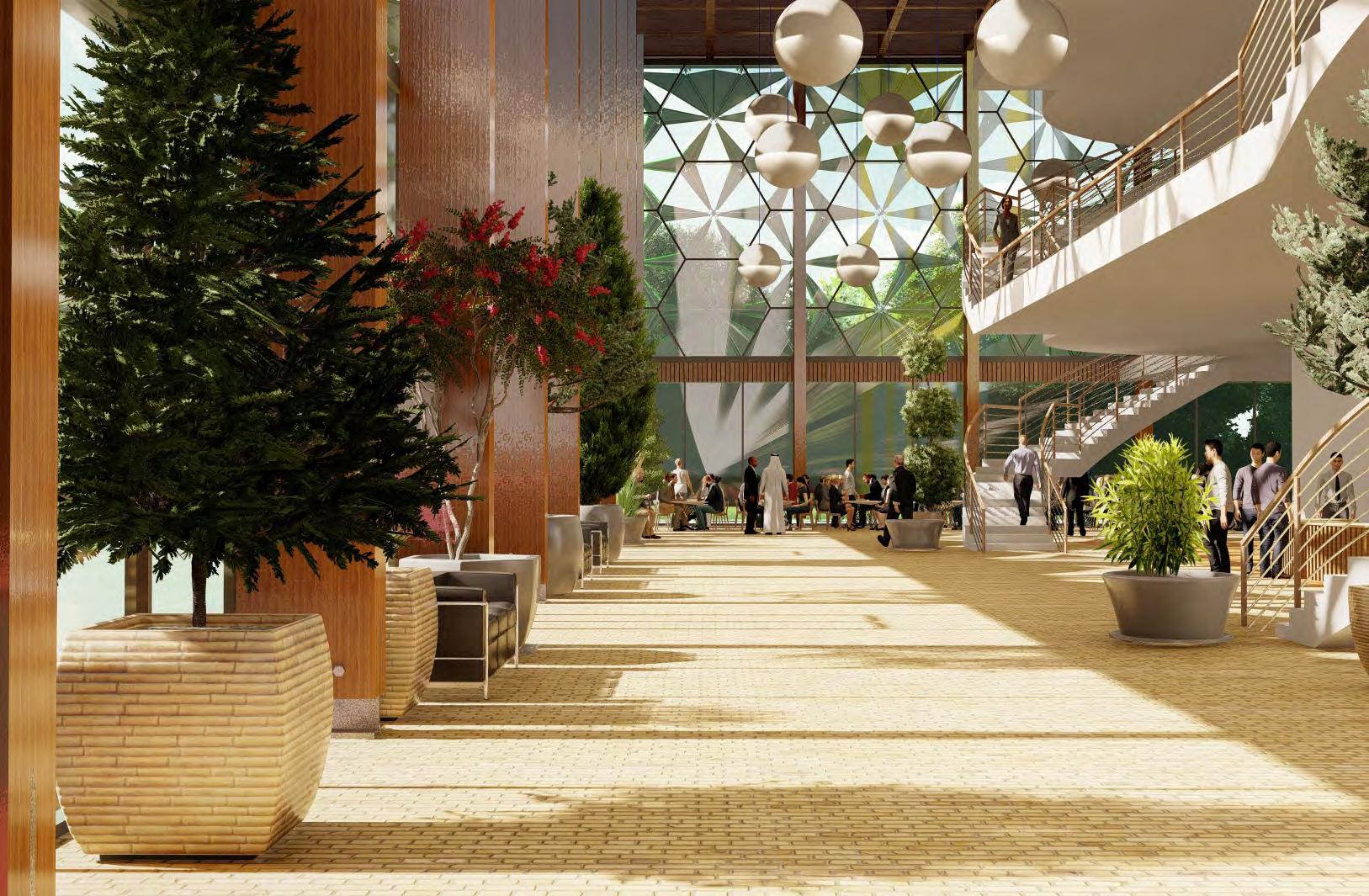
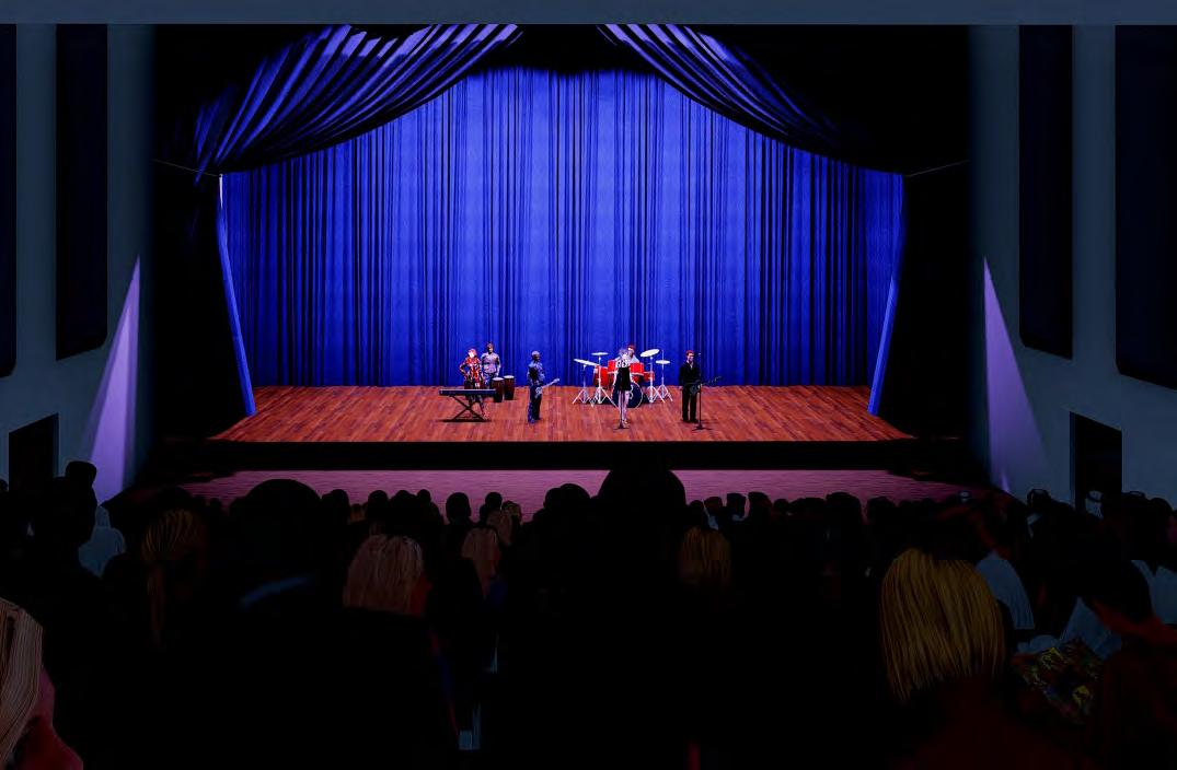
The Tower of Babel narrative reminds us that achieving cultural unification requires more than a mere desire for unity—it demands open dialogue, empathy, and an acknowledgment of the unique identities that exist within each culture. Inspired by this concept, the proposed building aims to symbolize the power and magnificence of collective effort. It will provide spaces that facilitate the harmonization of the diverse cultures found in the Old Kent Road area through the universal language of music. The building will serve as a hub where artists from various cultural backgrounds can learn, collaborate, and perform music from different cultures, fostering interaction within the diverse community
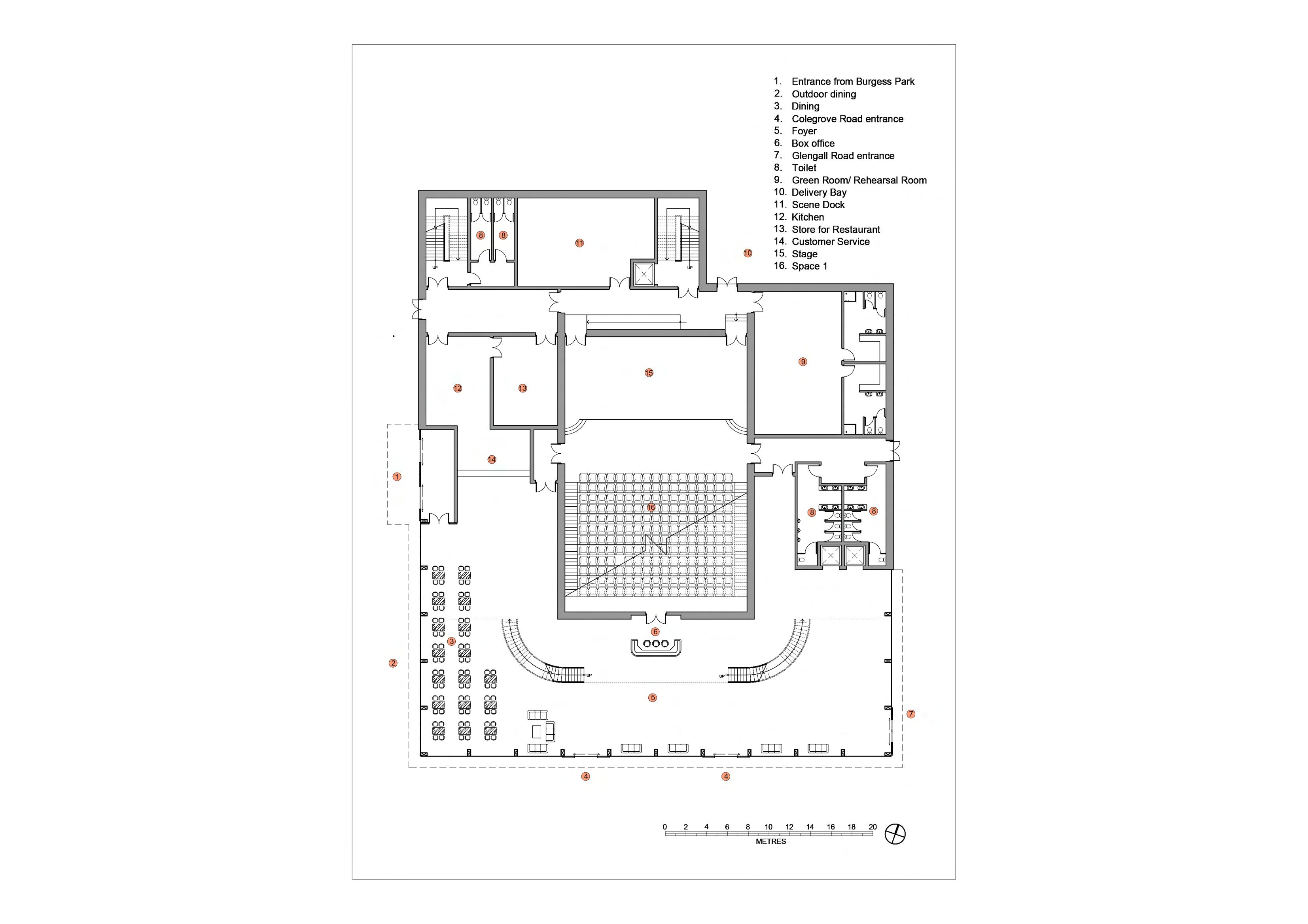
1. Entrance from the Burgress Park 2. Proposed Car Park 3. Stone paving at the front of proposed building 4. Entrance from Glengall Road 5. Loading bay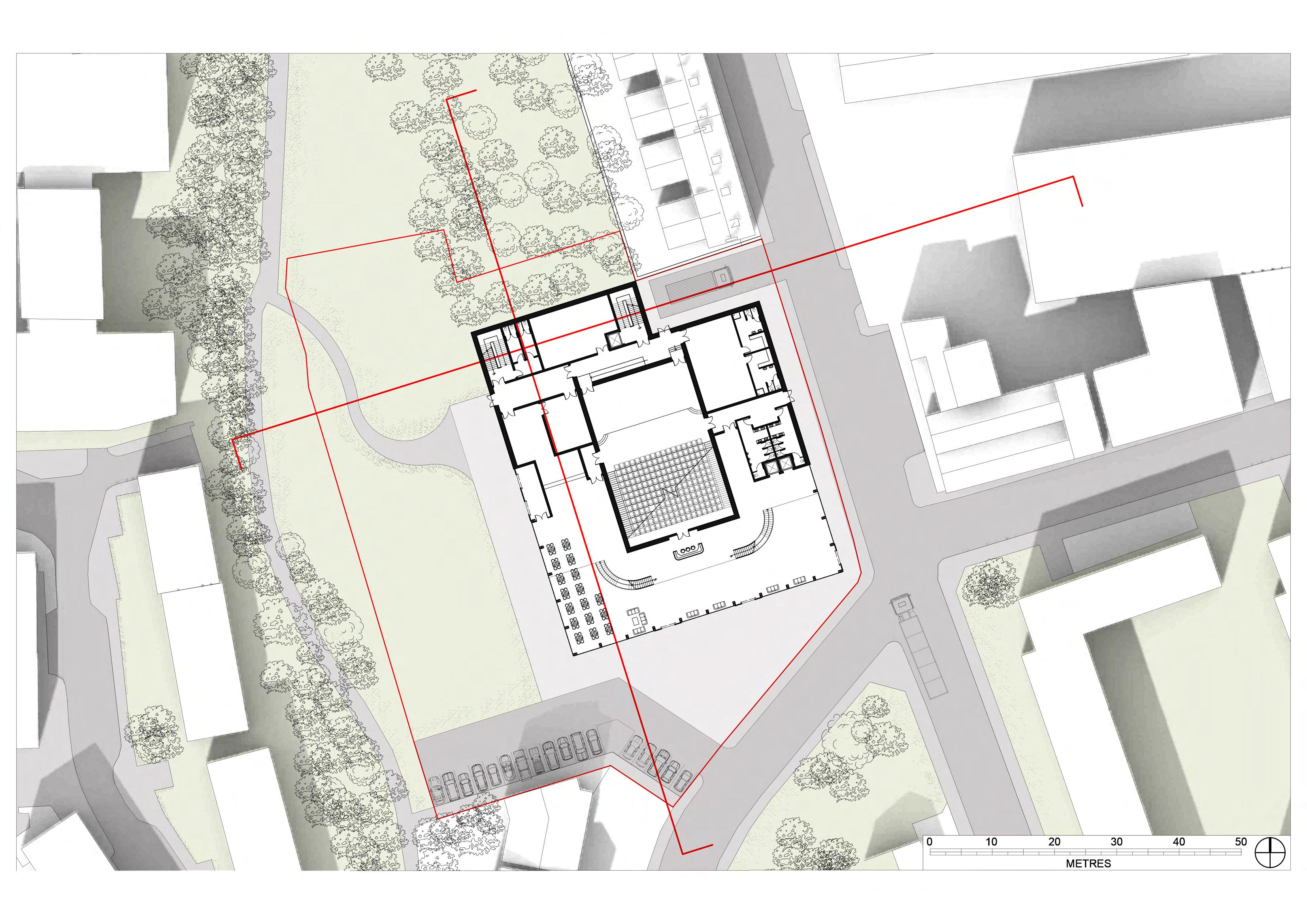


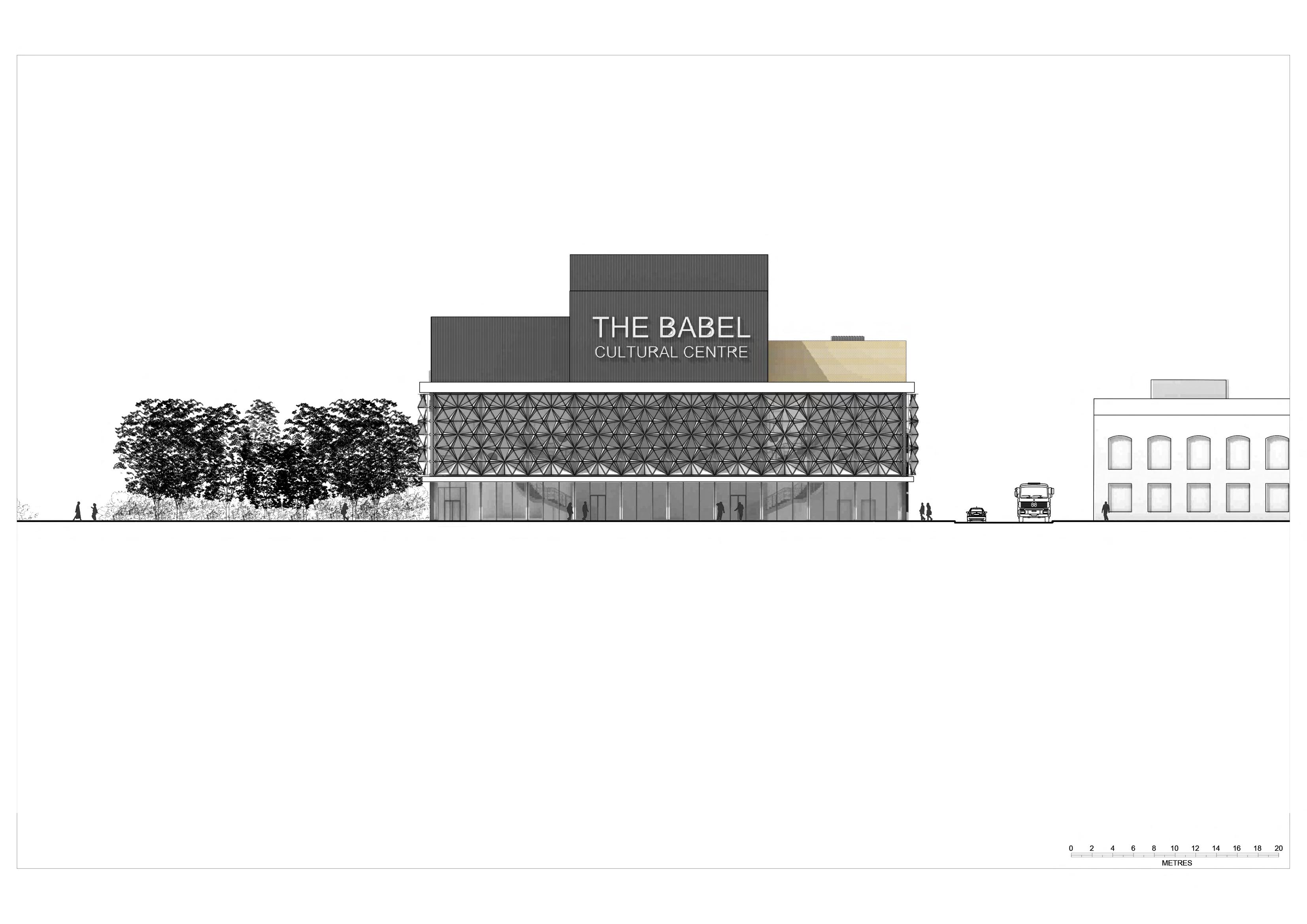

 Front/ South Elevation
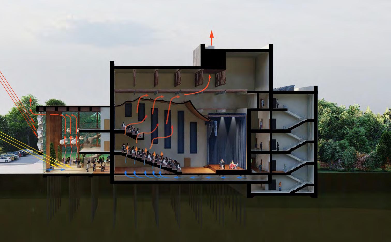
1. Summer, High Sun angle
2. Winter, Low sun angle
3. High thermal mass reclaimed brick floor.
4. Air filter/Damper room behind stairwell
5. Plenum under the theatre
6.Fresh air enters through plenum from underneath the seating area
7. Air heats up by audience budy temperature.
8. Warm air raises up and pull into extract plenum
9. Vitiated air out of extract chimney

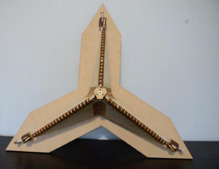
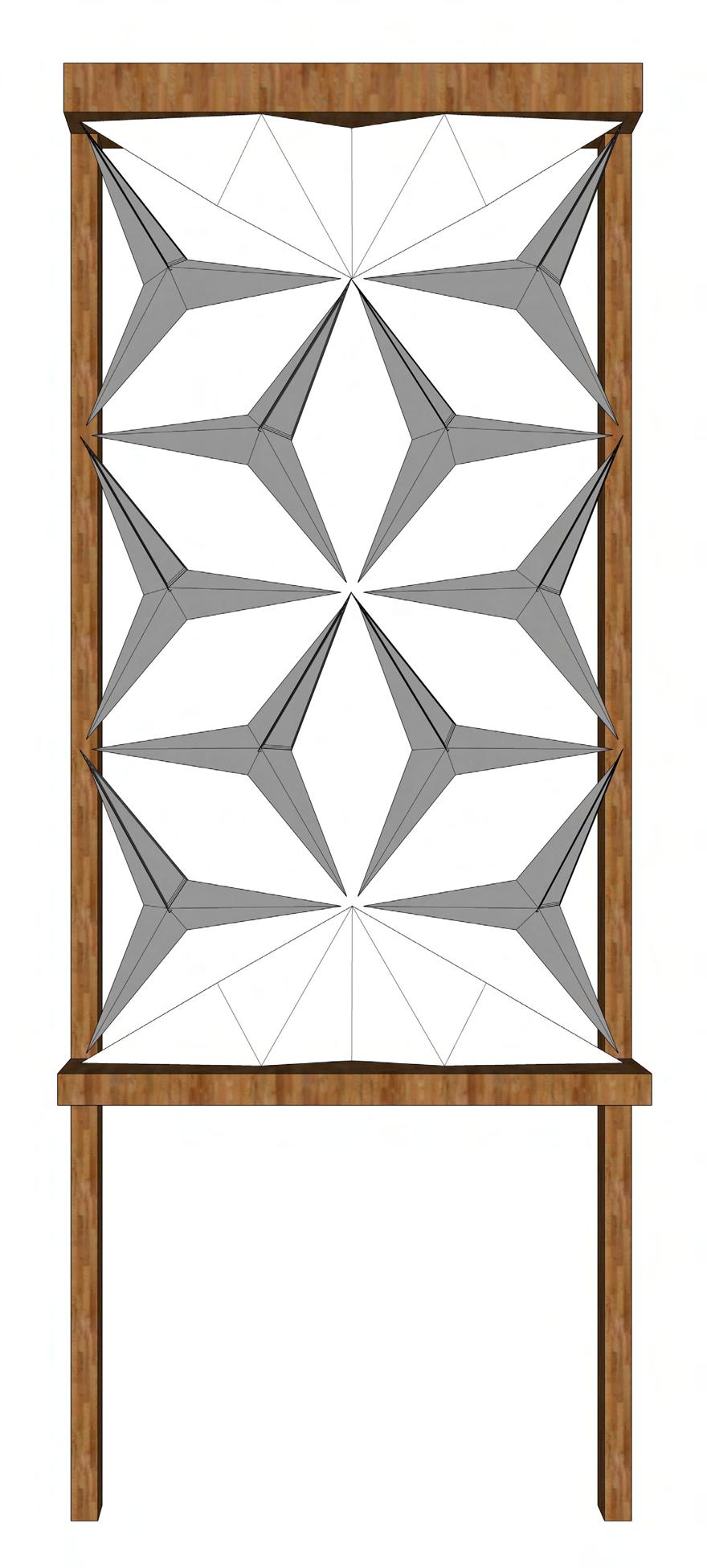
Kinetic facade architecture is an innovative design approach that integrates movable elements into the building envelope, creating dynamic and interactive facades. These facades can transform and respond to environmental conditions, user interactions, or pre-programmed patterns, adding a new layer of functionality and aesthetic appeal to the building.
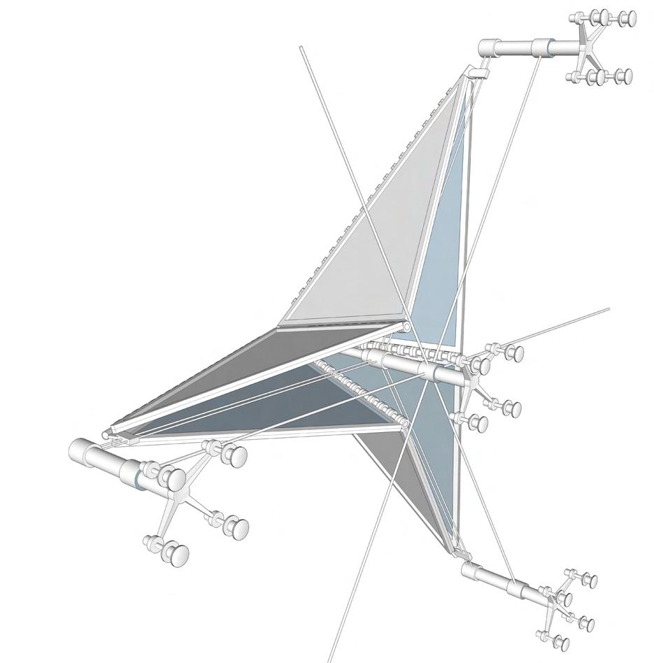
The use of kinetic elements in facade design allows for adaptability and flexibility. These elements can include various components such as panels, louvers, screens, or shading devices that can rotate, slide, fold, or change shape. The movement of these elements can be driven by mechanical, electrical, or even natural forces like wind or sunlight.
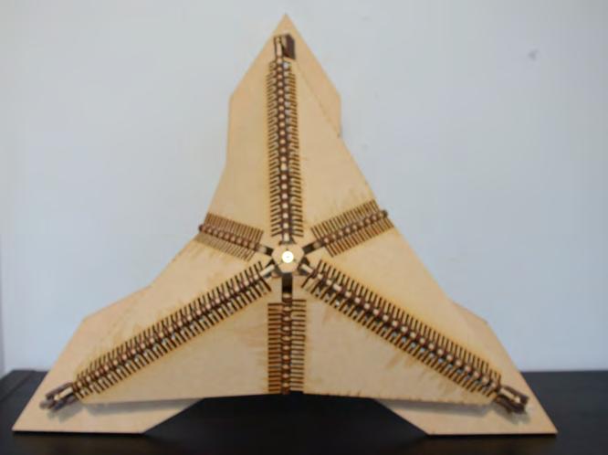

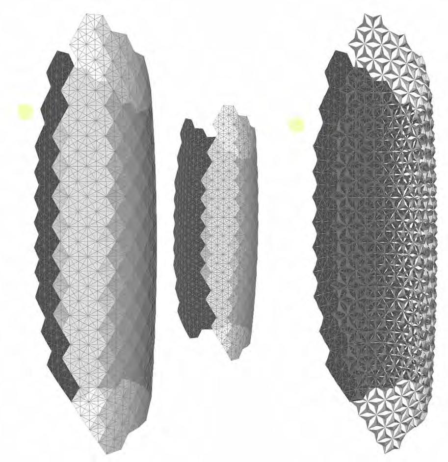
The benefits of kinetic facades are multi-fold. Firstly, they enhance the visual aesthetics of a building by creating an ever-changing and dynamic appearance. The movement of the facade elements creates a visually engaging experience for viewers, making the building stand out and capturing attention.
Secondly, kinetic facades provide functional advantages. They can dynamically control natural light, ventilation, and solar heat gain. For example, movable louvers can adjust their angles to optimize daylight penetration while minimizing glare and heat gain. This not only improves occupant comfort but also contributes to energy efficiency by reducing reliance on artificial lighting and cooling systems.
Kinetic facade architecture has gained popularity in recent years, especially in the context of modern and futuristic building designs. Architects and designers are exploring new technologies, materials, and fabrication techniques to push the boundaries of what is possible with kinetic facades. The integration of smart systems and digital technologies allows for precise control and monitoring of the facade’s movements, enabling real-time adjustments and creating adaptive building envelopes.


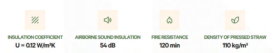
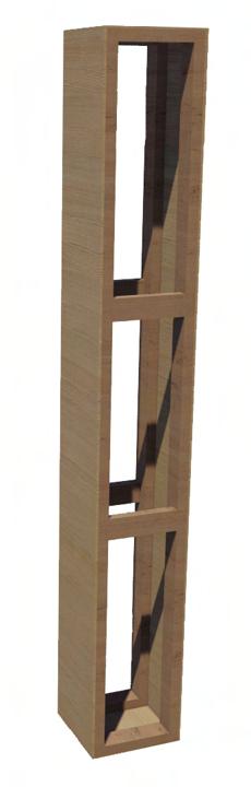
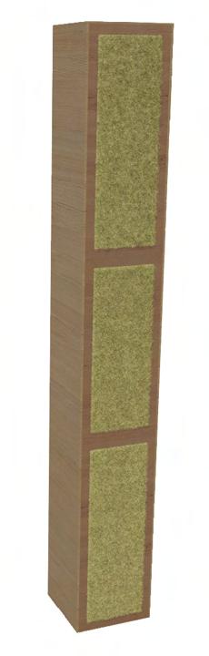
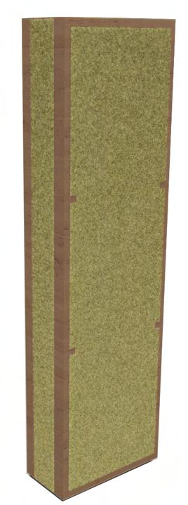
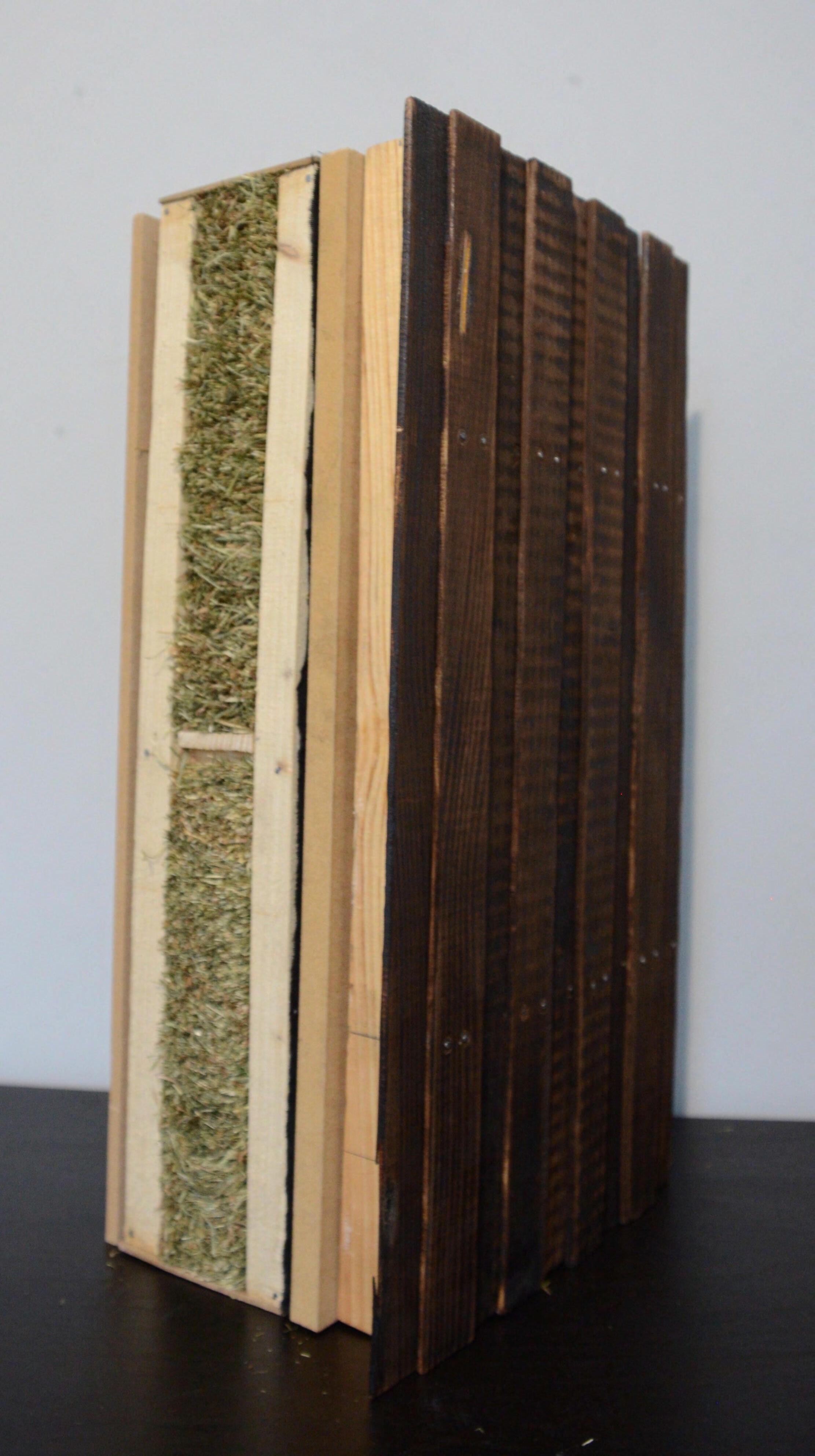
Technology Straw bale insulation panel by Eco-cocon
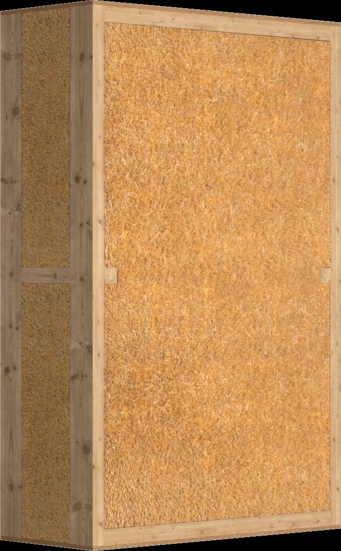
Why Straw bale insulation?

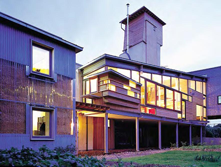
Straw bale panels have emerged as a highly significant and sustainable insulation material in modern construction. Their importance lies in their exceptional thermal performance, cost-effectiveness, and eco-friendly nature. By utilizing straw, an abundant agricultural byproduct, these panels help reduce waste and carbon emissions, making them a renewable and environmentally responsible choice. Their superior insulating properties ensure optimal energy efficiency, effectively regulating indoor temperatures and reducing the need for excessive heating or cooling. Additionally, straw bale panels are easy to handle and install, making them a practical choice for both professional builders and DIY enthusiasts. Embracing straw bale panels as an insulation material not only supports sustainable building practices but also contributes to creating healthier and more energy-efficient living spaces for a greener future.
Total volume of straw in use = 777.6m3
embodied carban per m3 by straw as building material = -128.2 kg CO2 eq
So, Total embodied carbon into the building by straw as building material = 777.6 X -128.2 kg CO2 eq = -99688.32 kg CO2 eq


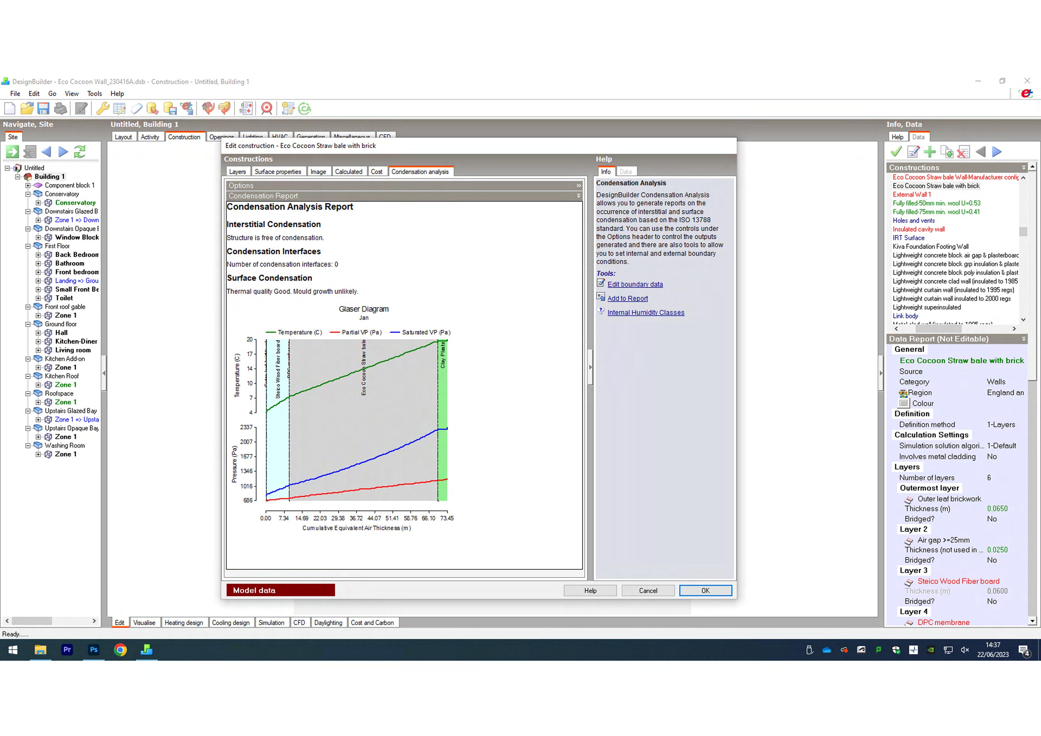
Calculating
is the thermal conductivity of specific material


Project 845: Harbourside Porthleven

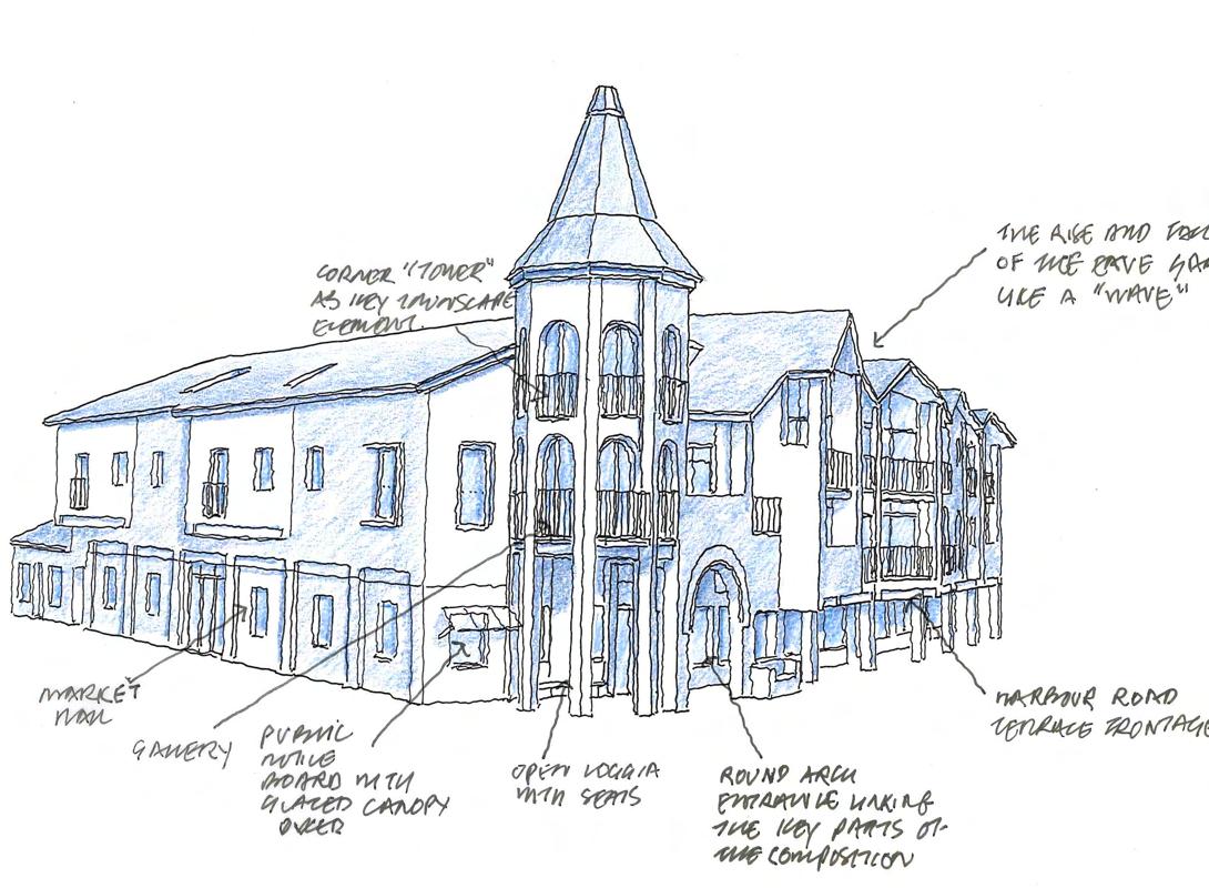
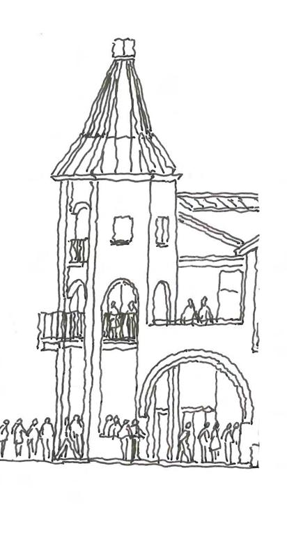
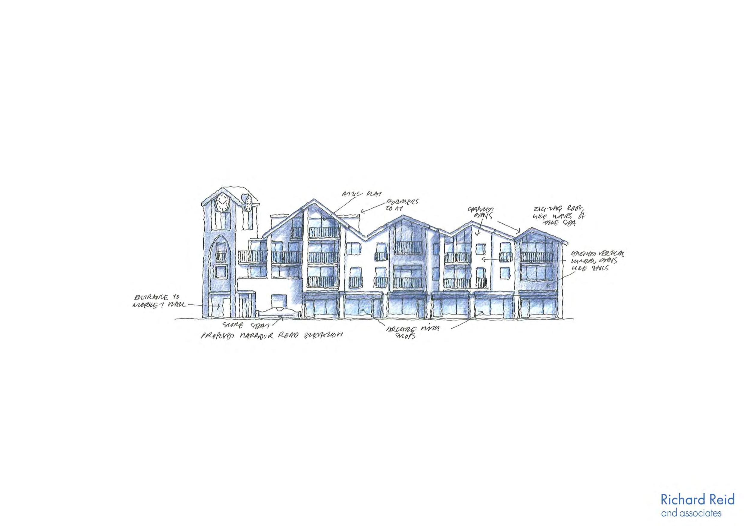
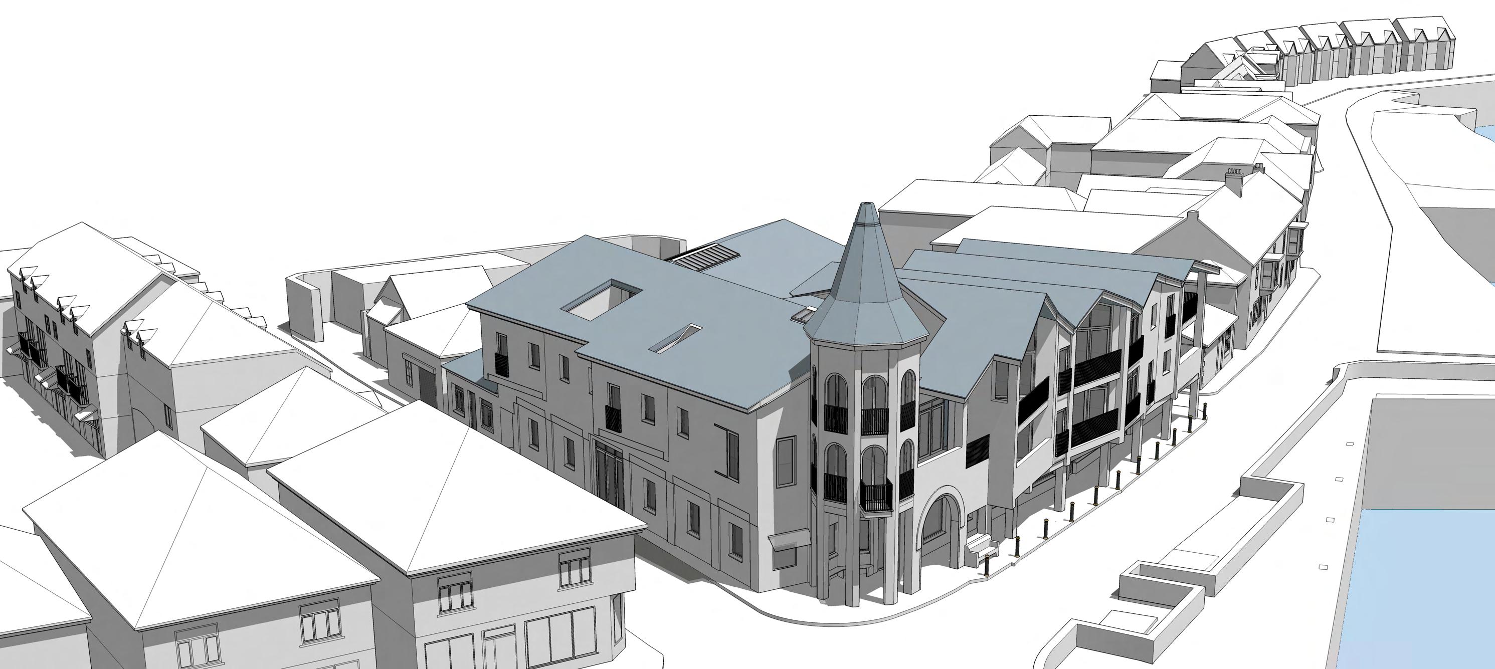
The site of the proposed is part of the land forming the corner with Commercial Road, Shute Lane (the original builder’s yard) and the Harbour Hotel. The existing single storey buildings that define the corner of this site are shown on the current OS map. The client would like to demolish the existing buildings and replace with a more appropriate mixed-use development including a Market Hall, shops, a restaurant, an artists’ loft, small gallery and 10 apartments. The site on the corner of Commercial Road and Shute Lane is on the eastern side of the Inner Harbour as noted in the Porthleven Conservation Area Appraisal and Management Study (April 2010) as an “Opportunity Site”. Whilst there are a number of opportunity sites on the western side of the harbour, this site is one of the few opportunity sites on the eastern side of the Inner Harbour.
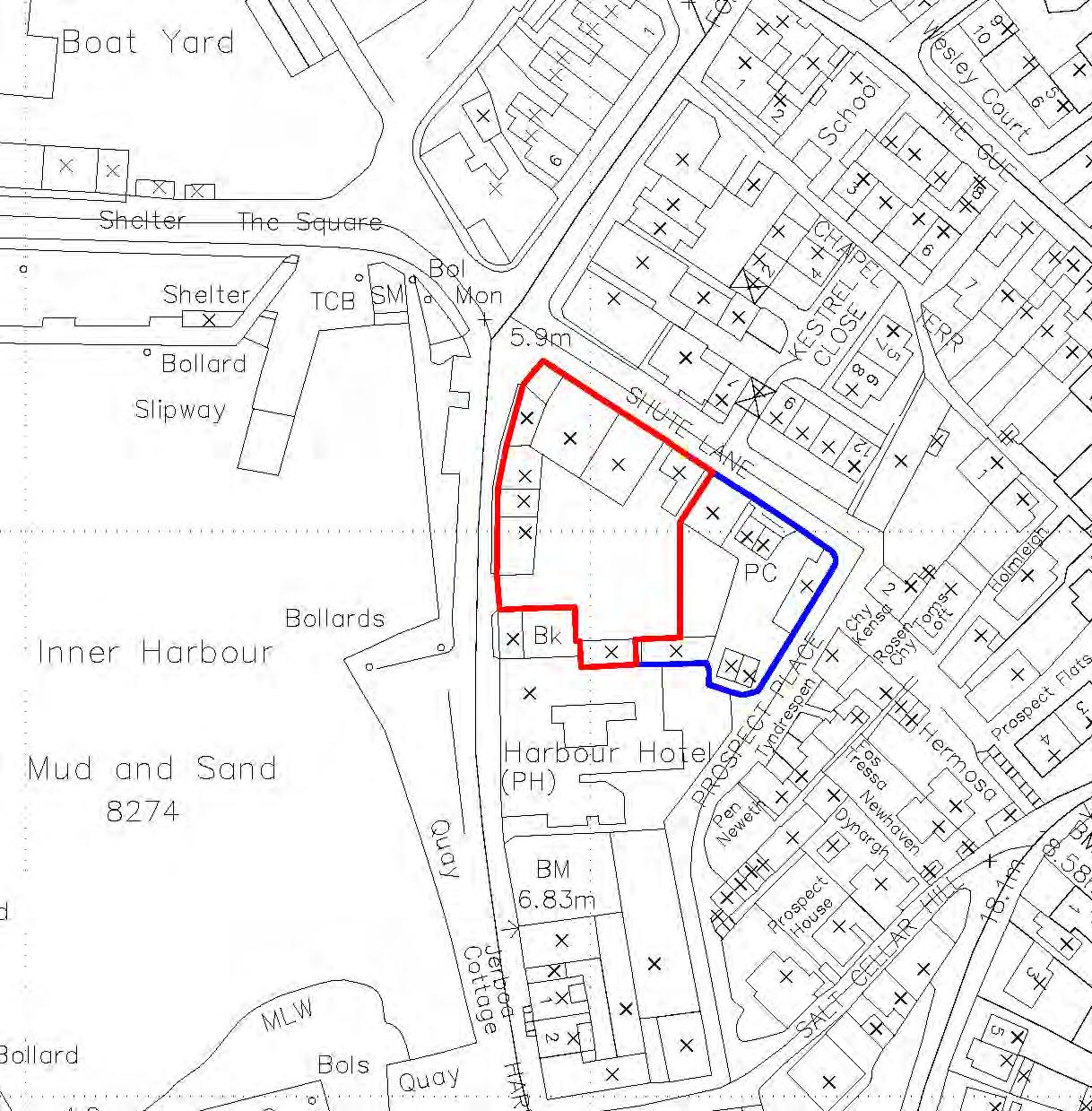
The existing site, whilst not marked by any significant architectural structure, is, in its location, one of the most prominent sites in the centre of the village. The proposed building wraps this corner site, enclosing a smaller inner courtyard with the shops opening out onto it. restaurant will have an outdoor terrace. This small courtyard will be appropriately landscaped.

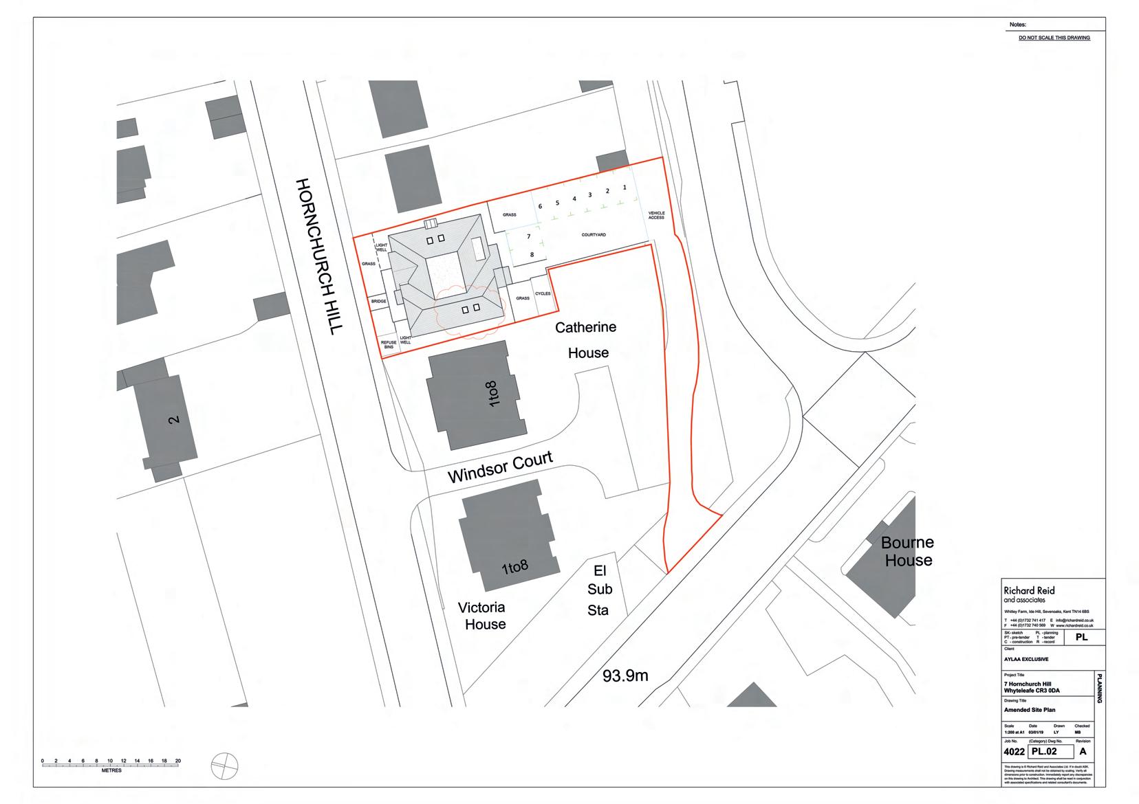
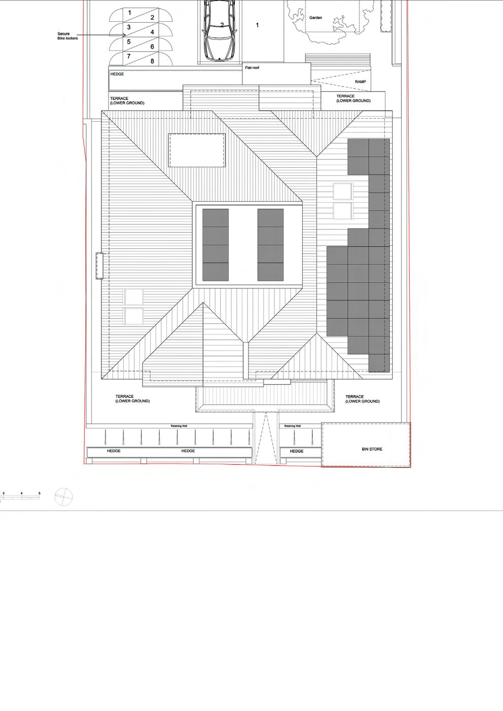
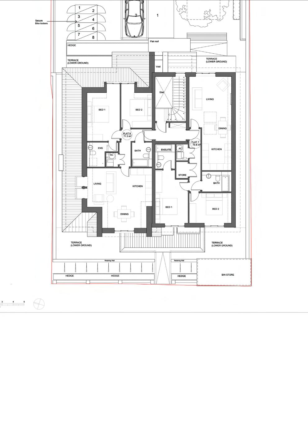
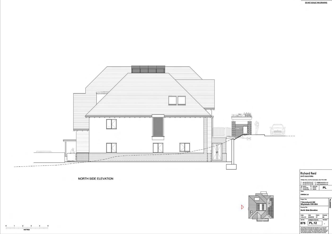
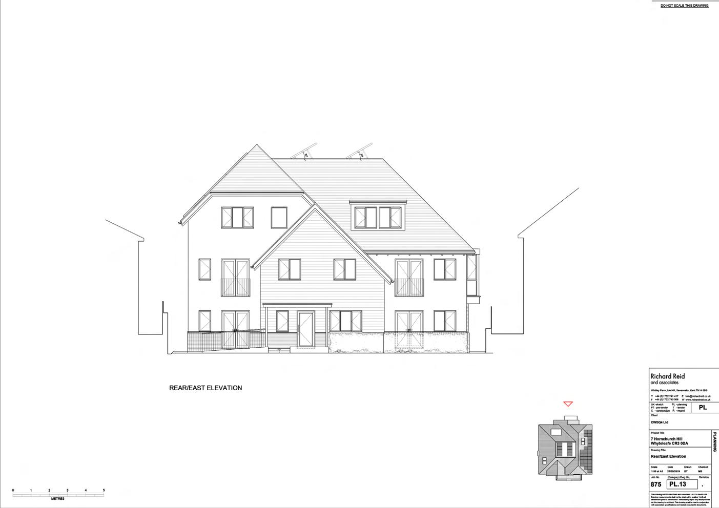
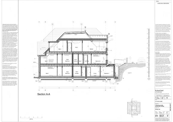
Project 875: 7 Hornchurch Hill, Whyteleafe
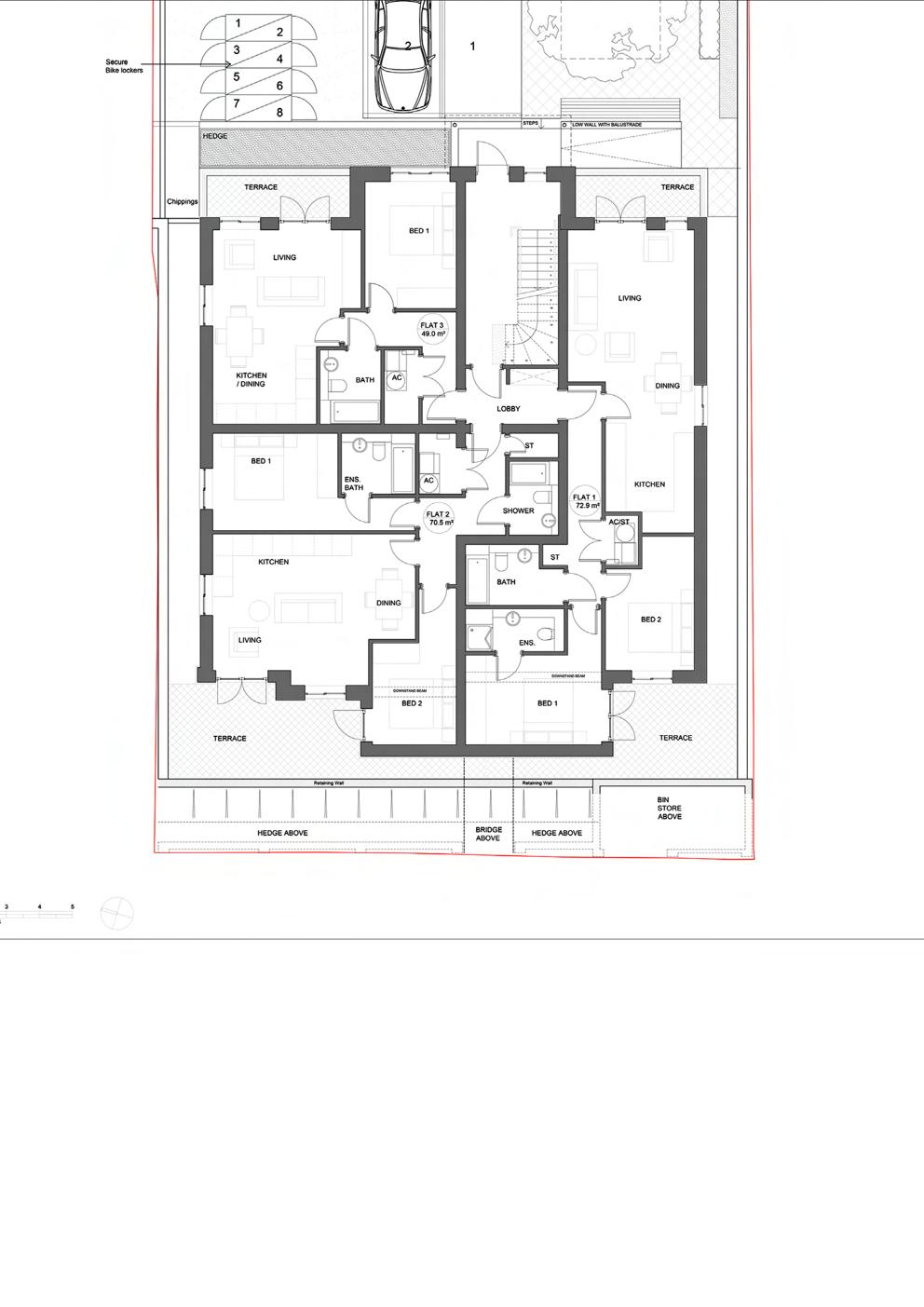
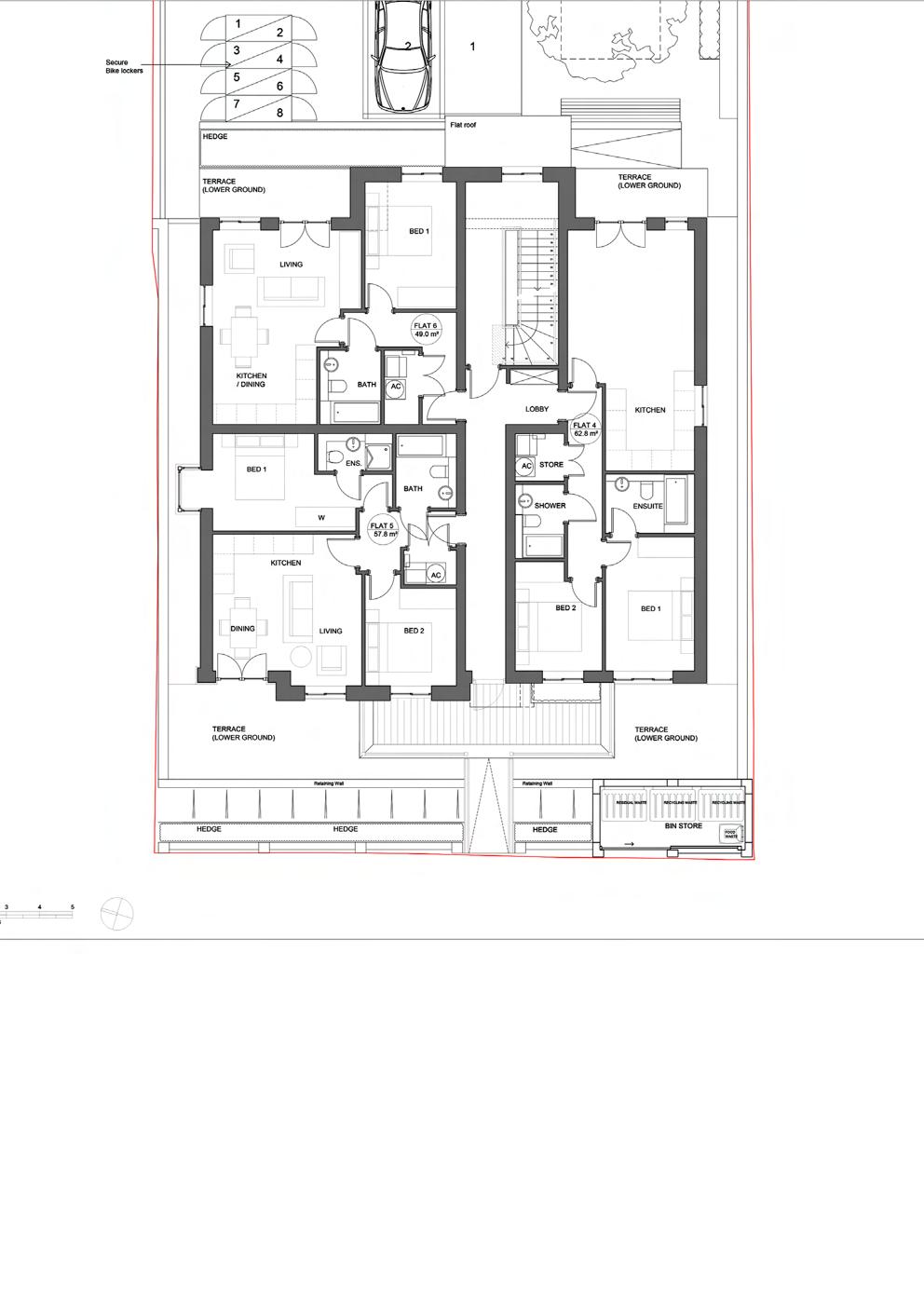
This project entailed demolishing an existing detached house in Whyteleafe, London and replacing it with a new block of eight apartments with associated parking, cycle, bin stores and garden amenities. The first planning permission for this was granted on 21 December 2017. The approved scheme was later modified to allow changes to the approved roof and dormers, removal of an upper floor balcony and replacement with a Juliet balcony, repositioning of windows and establishment of ground levels and ridge height. The second revised planning application was approved on 10 January 2019, and since then the proposed scheme has been developed into a full set of construction drawings.
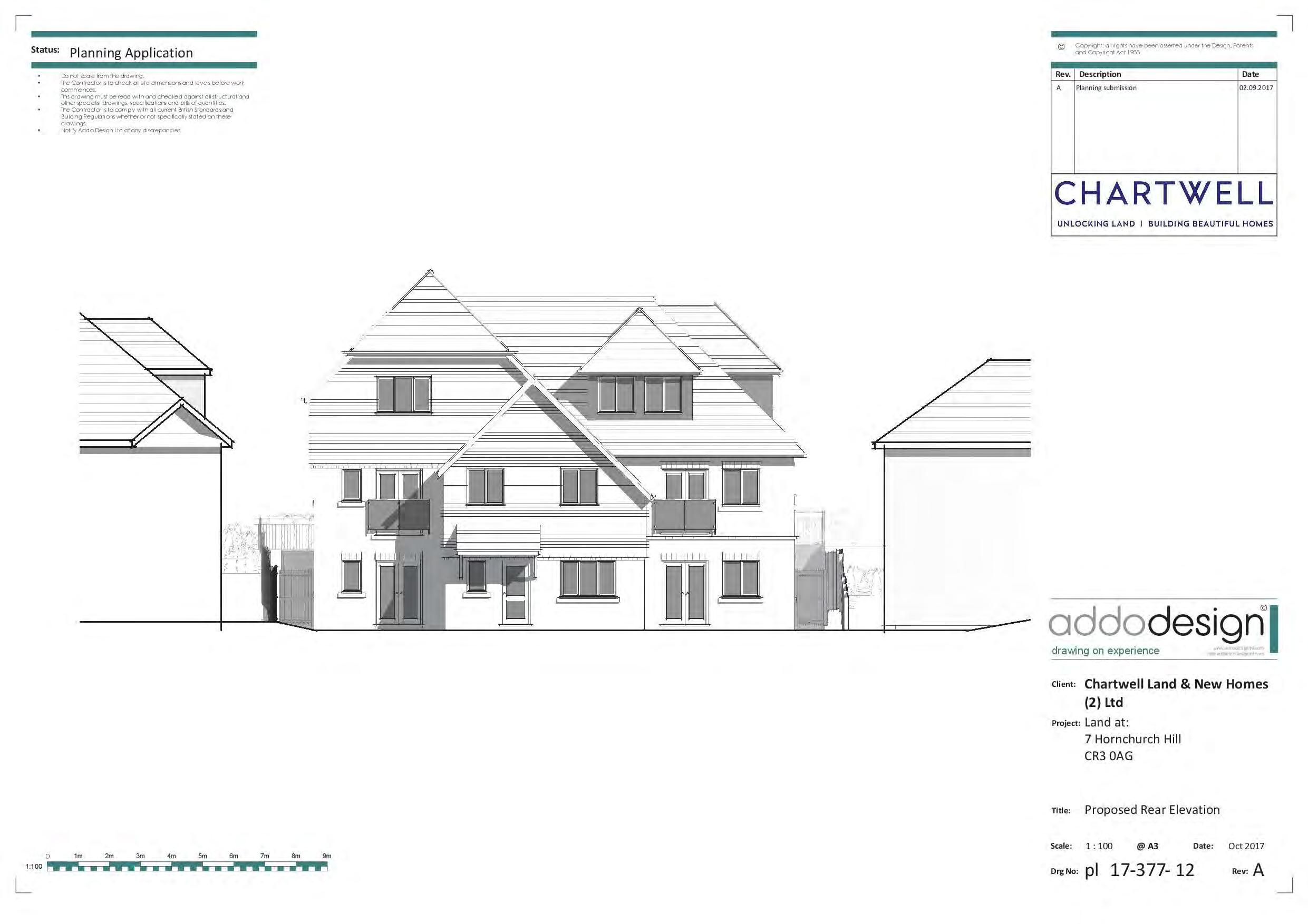
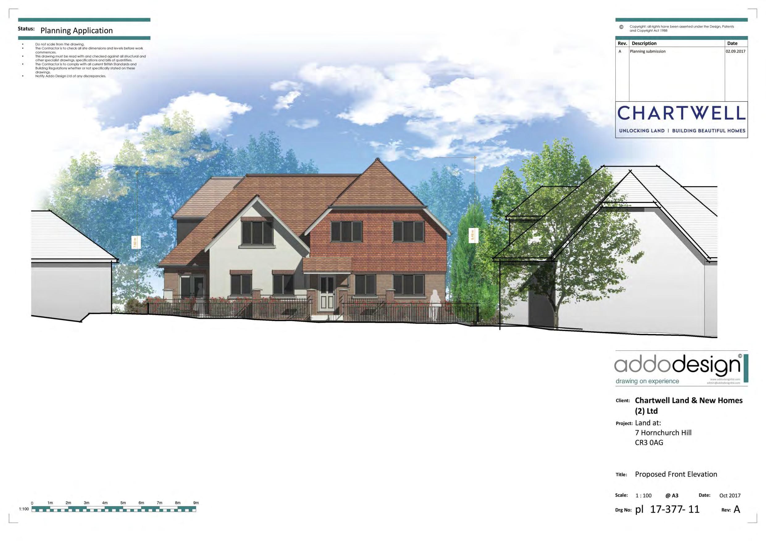
During this detail design and development process, some non-material amendments were made to the proposals including internal altercations to the floor plans; minor amendments to the size or location of fenestration; amendments to the external building materials; alterations to the projecting canopies; alterations to design of building to address land form/ retaining wall issues; addition of 36 photo voltaic cells on the flat roof area and south facing roof, proposed to cut the building’s carbon footprint using a green renewable energy source.


W3
Redland Concrete Plain Tile (terracotta); hung on 25x38mm impr sw battens (centres to suit tile fixing), and 25x38mm impr sw vertical counter-battens at 400mm centres; on Kingspan Nilvent breathable membrane (or similar approved); on 100mm wide 7N/mm² blockwork; 60mm cavity; external face blockwork supported using Ancon 'Staifix' STF6 timber frame wall ties (or eq. approved) that can accommodate movement, suitable for cavity width centrally nailed to timber studs through breather membrane and OSB board; typical tie spacing to structural engineer's specification; (for timber framing, see main W1 description). W1b
W1b: Brickwork plinth external wall (Target U Value: 0.16 W/m²K) Plinth to base of external walls formed by raising standard 100mm concrete blocks up to a 15.125 setting out height. Using a combination of Michelmersh 'PL.3.2 Plinth Stretcher' special bricks and standard 102mm bricks cut in half lengthways (giving two 48mm half bricks), target plinth masonry thickness of 158mm is achieved. (Where internal and external corners occur, use Michelmersh PL.4.2 and PL7.2 corner specials as appropriate). Beneath this cant course, outer cladding formed using more 48mm cut brickwork, jointed together to Structural Engineer's detail. 60mm cavity; with external face 100mm blockwork supported using Ancon 'Staifix' STF6 timber frame wall ties (or eq. approved) for timber framing, see main W1 description).
+14.075 Ground Level
A Min. 250mm clear void
value.
Visqueen (or Eq. Approved) 'Zedex CPT' DPC 150 Cut Block Cut Block Cut Block Cut Block Type TFC Timber Frame Tray by Cavity Tray Ltd (or equal approved) Eaves course tile Ex. 70 x 70mm timber tilting fillet with 6mm fire resistant board
Ancon 'Staifix' STF6 timber frame wall ties (or equal approved), at centres to be advised by Str. Engineer
Cut Block Cut Block
Standard Michelmersh 102mm bricks cut in half lengthways (giving two 48mm half bricks)
W1: Timber framing, (by specialist timber frame contractor), to be 140x38mm European Red / Whitewood graded C16 and C24 as required, with studs at 400mm 600mm centres as required. External panels to be sheathed (UNO) using 9mm Oriented Strand Board or exterior quality type OSB3; protected with enhanced breather membrane. GF sole plates to be connected to substrate using fixings specified by timber frame contractor; on a DPC.
Install 42.5mm Kingspan Kooltherm K118 (or eq. approved) laminated insulation board with fibre-free rigid thermoset phenolic core and integrated vapour control layer to inner side of wall; fully taped and jointed; Install a second layer of wall board (staggered joints with primary wall) to achieve 60min fire resistance; apply plaster skim internal finish.
Vapour Control Layer
100 40 42,5 60 12,5 100 F1: Ground Floor; Residential Flats Target U Value: 0.16 W/m²K Allow 25mm for floor finishes to be installed outside of this contract by Client
Breathable membrane
of FFL=
(top
OUTSIDE FLAT 3 +13.69 SSL Top of
R4
F1
65
25
62.5mm Kingspan K118 insulated plasterboard 50 x140 50
Min. 50mm oversite concrete on 50mm sand blinding Visqueen (or eq. approved) high performance dpm 1. Do not scale from drawings read figured dimensions only. 2. Refer to Engineers details regarding construction of ground slab and foundations. 3. The contractor is responsible for checking dimensions tolerances and references. Any discrepancies to be verified with the architect before proceeding with the works.
20.89 50 x140 150
W4 FFL: +14.30 Ground Floor Flat 3 140
Glidevale AV50 AbVent (or similar approved) installed under top edge abutment to provide ventilation to the roofspace equivalent to 5000mm²/m
12.5mm wallboard and 3mm plaster skimcoat
62.5mm Kingspan K118 insulated plasterboard
Vapour Control Layer
150mm Kingspan
150mm Kingspan 'Kooltherm' K7 insulation between 40mmx38mm C16 softwood pressure treated studs at 400mm c/c
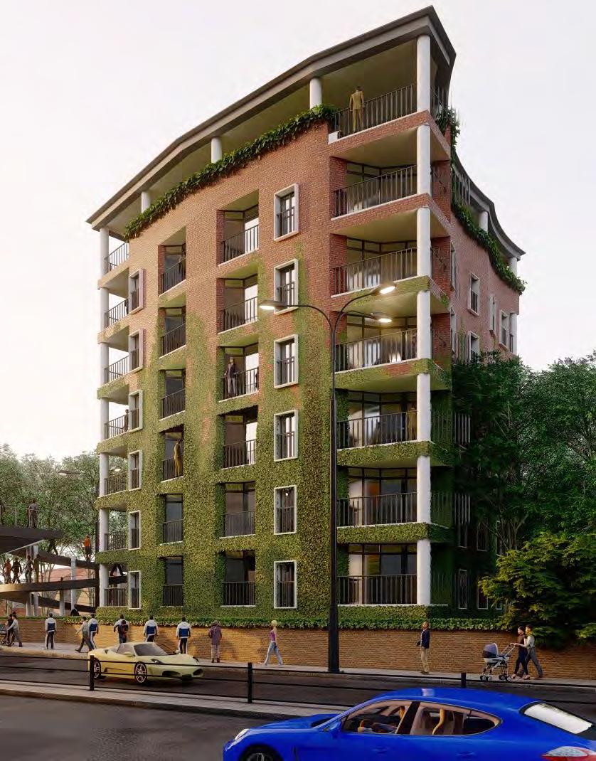
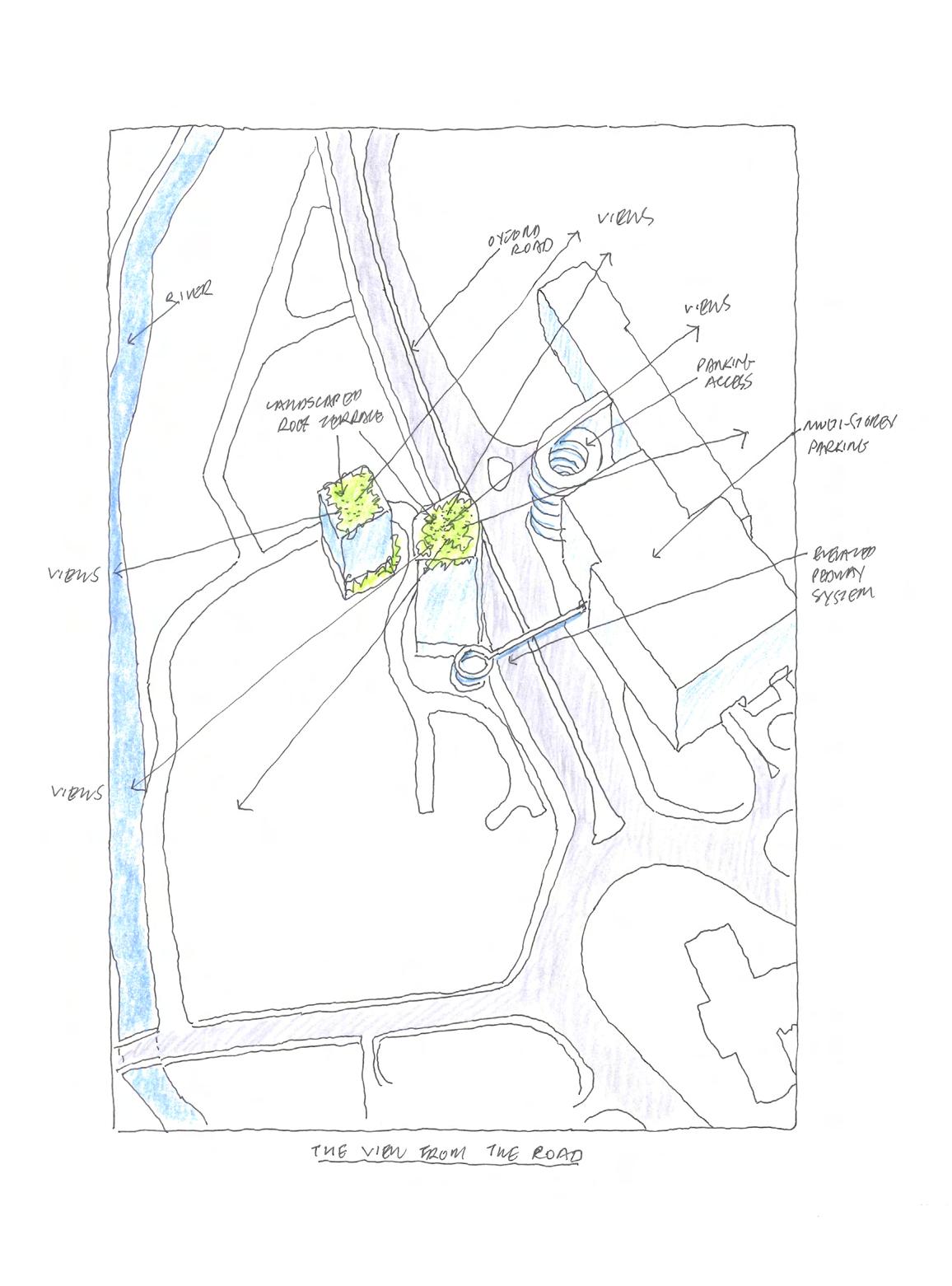
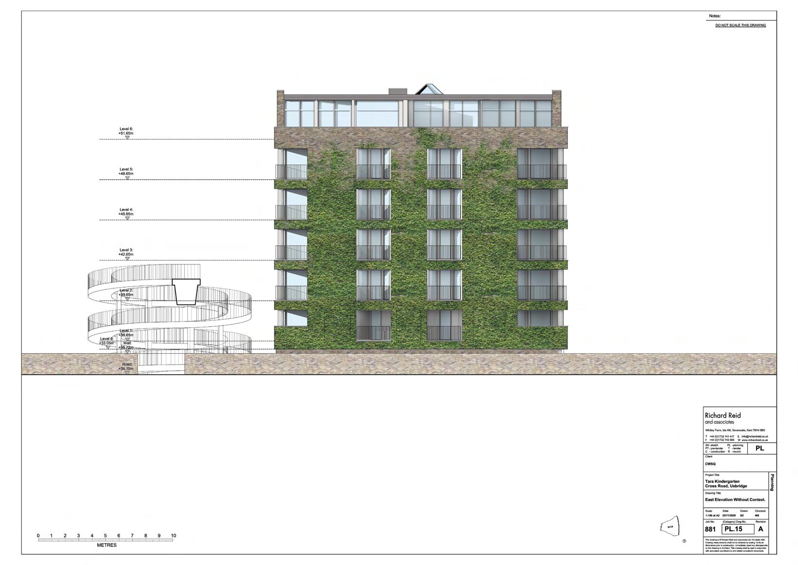
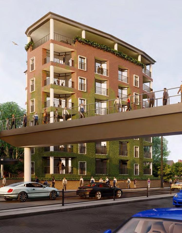
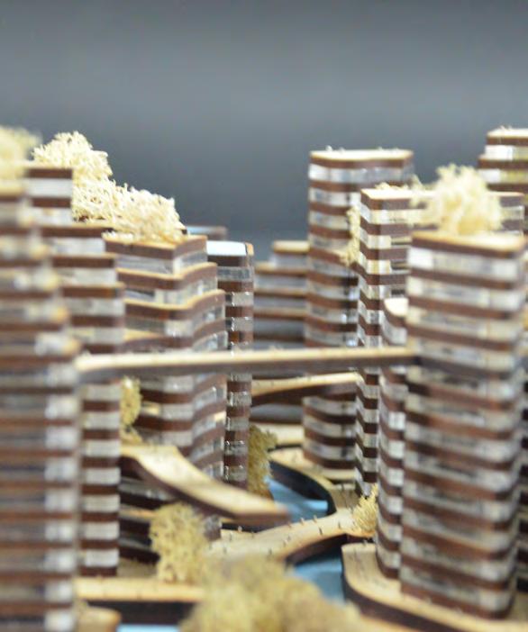
Project 881: Tara Kindergarten, Uxbridge
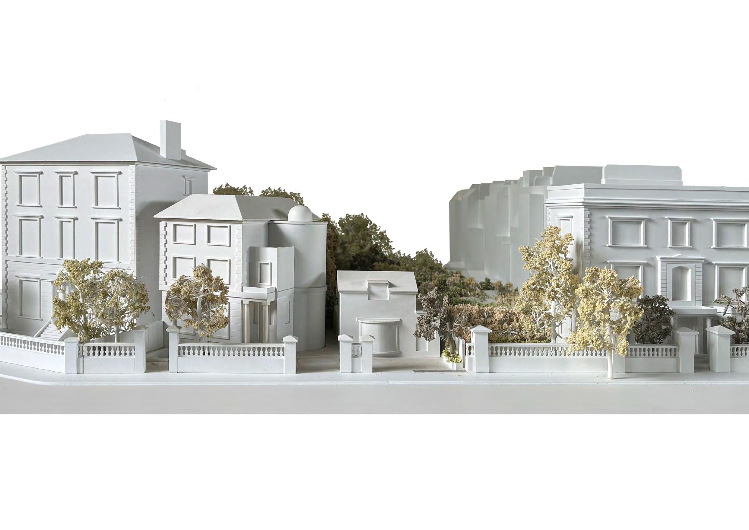
The site of the Tara Kindergarten is on the west side of Oxford Road, by the circular ramp giving access to the pedestrian bridge crossing Oxford Road to Crown Walk and the shopping centre facilities and multi-storey Grainge’s car park along the east side of the road. The children’s nursery site is bounded by the curve of Cross Road, which links Lawn Road, on the northwest and provides access to Lynch Lane along the south. The site is included in the Designated Conservation Area, the boundary of which runs along the edge of the dual carriageway of Oxford Road, enclosing the Fray’s River and the northern section of Fassnidge Park.
The proposal is the demolition of the existing bungalow and the erection of a residential apartment block. The new building will comprise a socially balanced community with mixed-use spaces, including a nursery, and assisted living accommodation. New proposal offers apartments will range from single bed studios to three-bedroom duplex units, accommodating residents of different ages and backgrounds. The design has been carefully considered to ensure good acoustic separation between units, with walls and A floors arranged for optimal sound insulation. The ground floor will be a space for existing nursery and will connect green spaces to enhance biodiversity and landscape design.


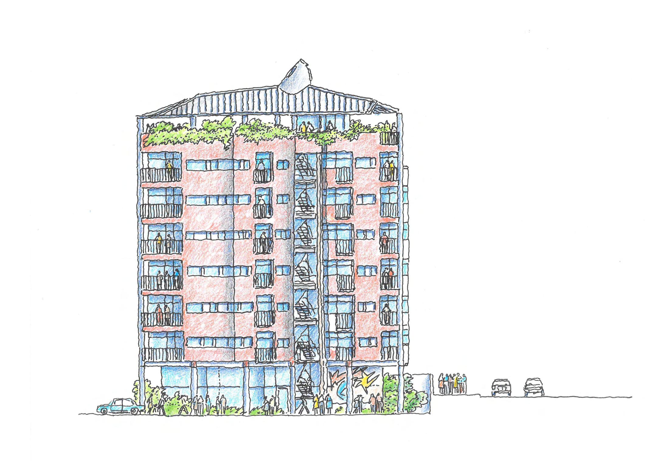

 Right/North Elevation
Left/South Elevation
Front/West Elevation
Rear/East Elevation
Right/North Elevation
Left/South Elevation
Front/West Elevation
Rear/East Elevation


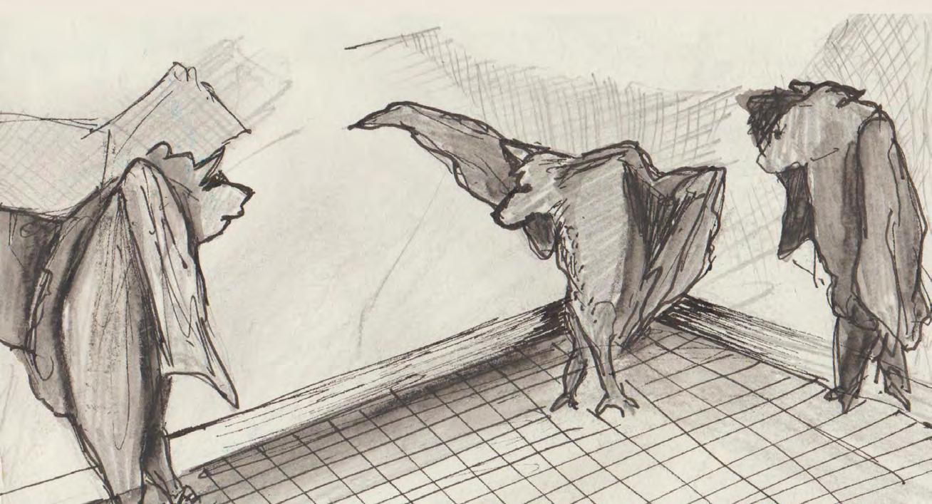
When life turns you upside down, try viewing it from a different angle. You might find yourself dancing.