

What is Sugatsune's "Motion Design Tech"?
Motion Design Tech is Sugatsune's unique product concept to provide specialist movement solutions for your flaps and doors. The operability of doors, lids or loads can be improved by choosing from the 6 types of motion suitable for work environment. It can also improve the efficiency of work involving opening and closing movements, increasing the added value of the device and equipment.
Motion Design Tec creates the ideal motion for customers, boosting user confidence to help people achieve their goals with ease and precision. So where should they be used separately? We will introduce them one by one.

Stops at any angle
Free Stop Motion
It can hold the door, lid or cover in any position during operation.
Applicable Places
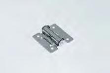

Ideal for top-opening covers in a production line, as it allows for the cover to be held open in any position. Because no stopper is necessary,
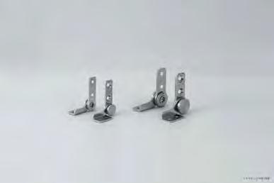
No stay is needed, clearing additional space inside the machine. Users don’t have to worry about slamming the lid closed, bringing additional safety and ensuring it remains damage-free.

Stops by means of friction


Silent and safe Soft Motion
Reduces the opening/closing speed of doors, lids or drawers.
Applicable Places
This is ideal for wall-storage or information terminals in hospitals. Once used and the flap is lightly pushed up, it will slowly and naturally close. This is a perfect solution for quiet environments.
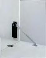

SMOOTH MOVEMENT
Lifts and opens easily Assist Motion
Assists in opening/closing heavy doors, lids or covers.
Applicable Places
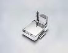
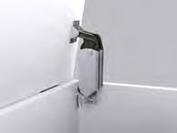
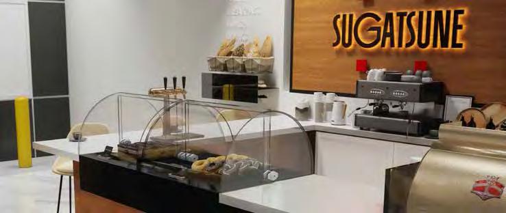
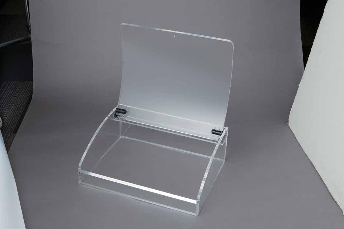
This is suitable for food display cases such as self-serve bakery cases and candy or sweet cases, etc.
If the flap is pushed down slightly, it will close naturally and slowly by itself. (It isn’t necessary to hold the flap until it closes completely)
SMOOTH MOVEMENT

Reduces speed by means of resistance


Ideal for a large sized analyzing device and enables a heavy flap to be opened using little power.
Anyone can easily handle it with one hand - neither the opening nor closing operation will burden users.
Lifts by means of reaction force


Orifice Structure Resistance develops when a viscous medium flows from a thick diameter to a thin diameter.
Shear Structure Resistance develops when moving the two plates with the viscous medium between.
“Lapcon" refers to Sugatsune’s patented damper mechanism using left structures.
LIGHTENS LOAD
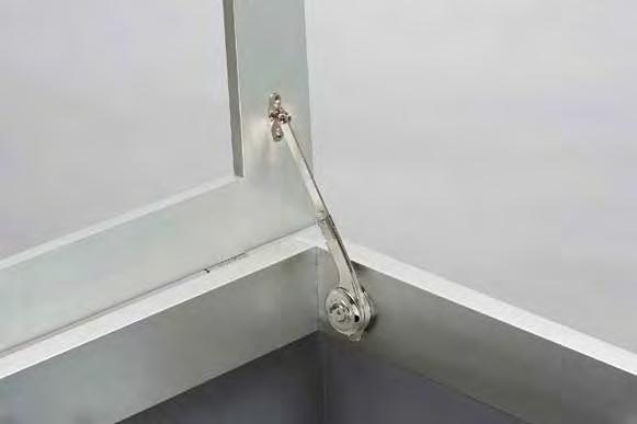
Heavy Duty Spring Loaded Lid Stay, S-AT02W
Lift Assist Hinge, HG-PA230
and fine operation can be achieved by using a spring suitable for the application.
Compression Spring Reaction force is generavted when the shrunken spring returns to its original shape.
Torsion Spring Reaction force is generated when the curled spring returns to its original shape.
Stainless Steel Lift Assist Hinge HG-JH210

Controlled & Seamless Multi-Linear Motion
Temporarily holds door, lid or cover during opening/closing at a certain angle with a unique feel.
Applicable Places
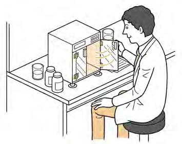
Ideal for a measuring device in a laboratory and enables a flap to be held at a certain angle. It also prevents a flap moving freely so users don't have to worry about it knocking down an instrument.
Applicable Places
Can be used for conveyor guide positioning units and workpiece extrusion units. Enables smooth position adjustments while supporting the guide bar and can be installed in narrow spaces where conventional linear guides could not be implemented.


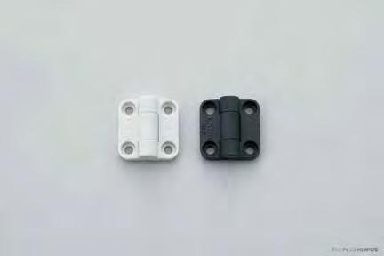


When rotating two grooved parts with balls between them, the moving balls will fall into the grooves, realizing temporary


The MLGX series features a unique dual-plate structure with eight rollers arranged at specific angles to evenly
The MLG series features a single roller clamped between two rows of balls, allowing it to bear loads from various directions.
holding.
Innovative openings Unique Motion
Expand variations of opening/closing locus.
Applicable Places
Ideal for large-size machines such as in food processing or printing. It enables a flap to move parallel to a body and decreases the space needed to open the door.
By using this mechanism, an open door will not obstruct narrow corridors in a factory where several machines are operating. The wide opening makes it easier to take something in and out.

One major advantage of “Motion Design Tech” supporting 5 types of motion Easy Installation & Adjustment Function
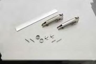
Proper installation is crucial for the performance of industrial components.

Since “Motion Design Tech” is a technology of motion, to further improve that “motion”, installation support function is incorporated in various products.
Easy installation and possible door adjustment after installation realises a comfortable fine opening and closing operation.

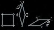
Combining multiple shafts and arms creates more versatile locus than moving with one shaft.
Locus of MonoFlat LIN-X hinge
Door projection is less than that of common swing doors.


Locus of concealed hinge
Even for overlay doors, the door





High durability is also proprietary to Sugatsune. Comfortable movement lasts for a long time.

Torque
How to Calculate Torque?
Torque is the force required to rotate something along an axis. It can be calculated by measuring the distance of the door or lid from the hinge side to the opposing edge and multiplying that by the weight of the door or lid. Then take the resulting value and divide it by 2.
Torque = (D x W)/2
Torque = .5 x D x W
Where:
D = Measurement of door or lid from hinge to edge. W = Weight of the door or lid
Selection of Torque Hinges
Formula for Torque Generated by The Door
The torque generated by the door can be calculated from (center of gravity) and (weight) of the door.
TORQUE generated by the door WEIGHT (kg) m DISTANCE from rotation center to door center of gravity (m) X1
Rotation center
The Torque Hinge to Use
L1 1 2 X 1 m
Door center of gravity
Example:
When installing two torque hinges as below picture, which one is the most suitable?
(Torque tolerance: 20%)
Torque hinge A (0.4 N·m / pc.)
Torque hinge B (1.0 N·m / pc.)
Torque hinge C (4.5 N·m / pc.)
Door weight 1.76 lbs. (0.8 kg) DoorHeight:15-3/4"(400mm)
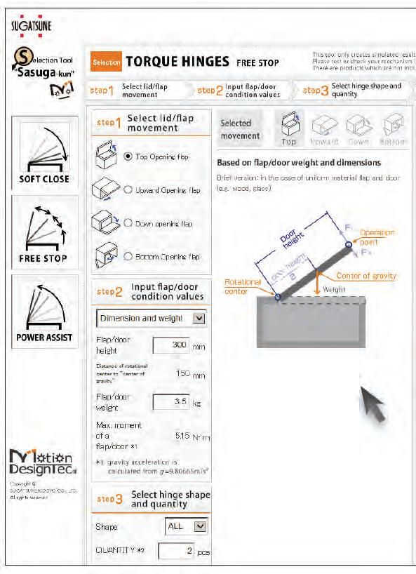
Keep in mind that the formula above assumes that the lid is “flat”. In many cases, lids are “L” shaped or have other attributes which need to be taken into consideration in order find the actual point of the center of gravity. To simplify your effort, we have created a tool that will do the calculations and suggest hinges in our line up that will fit your specific application.
Distance from rotation center to door center of gravity: 13/16" (20 cm)
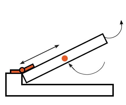
The most suitable torque hinge is:
Torque hinge A (0.4 N·m / pc.)
Torque hinge B (1.0 N·m / pc.)
Torque hinge C (4.5 N·m / pc.)
Formula
Door center of gravity
Online Tool to Simplify Your Selection Process
The torque generated by the door can be calculated as below:
0.2m x 0.8 kgf x 9.80665 ÷ 1.57 N·m N
The torque generated per hinge is: 1.57 N·m ÷ 2 ÷ 0.79 N·m
Torque has to be stronger than 0.79 N·m per hinge.
Considering torque tolerance 20 %, it has to be stronger than 0.95 N·m. The answer is: Torque hinge B (1.0 N·m / pc.)
Key Point for Selection
Important factors when choosing a torque hinge are the shape, the functions and the moment of the door, flap or cover being manufactured (below, door moment). The free stop function requires conditions in which the torque of the torque hinge exceeds the maximum door moment When multiple torque hinges are used, the torque of the hinges is equal to the torque value of each hinge x the number of hinges The same principle applies when using a torque stay.
The variance in torque value (tolerance) also needs to be taken into account when selecting a torque hinge. If the tolerance is ±20%, free stop will not occur unless the maximum door or flap moment is lower than the minimum torque value (-20%). Hinge torque

The SASUGA-KUN tool was designed to help calculate the torque generated by your door, flap or monitor and suggest suitable Motion Design Tec ® products that could work with your application. All you need to do is input values such as weight and dimensions, select a few options and conveniently find the right hardware.

AS9120B
This standard includes ISO 9001:2015 quality management system requirements and specifies additional aviation, space, and defense industry requirements, definitions, and notes.
It is emphasized that the requirements specified in this standard are complementary (not alternative) to customer and applicable statutory and regulatory requirements.
*Registered for Sugatsune America, Inc.
ISO 9001

Sugatsune Kogyo Co. LTD.
Management Systems Enhancement Department of the Japanese Standards Association (JSA) registers the Quality Management system of these organizations, which conforms to JIS Q 9001:2008, ISO 9001:2008
Design development, production and purchase sale of Furniture Fittings, Building Hardware, Machinery Hardware, Electronic and Communication Equipment Steel Furniture and Lobby Furnishings.
*Registered for Global Headquarter Sugatsune Kogyo Co.,Ltd.
ISO 14001

Sugatsune Kogyo Co. LTD.
Management Systems Enhancement Department of the Japanese Standards Association (JSA) registers the Environmental Management System of the above organization, which conforms to the following Environmental Management System standards within the scope in the Appendix specified below:
Environmental Management System Standard: JIS Q 14001:1996, ISO 14001:1996
Appendix: Appendix to the Certificate of Registration JSAE 597-2002
*Registered for Global Headquarter Sugatsune Kogyo Co.,Ltd.
NSF
NSF International RECOGNIZES SUGATSUNE AMERICA, INC. CARSON,CA
AS COMPLYING WITH NSF C2.
PRODUCTS APPEARING IN THE NSF OFFICIAL LISTING ARE AUTHORIZED TO BEAR THE NSF MARK.
SUGATSUNE's NSF Certified Products are designed to meet Food Equipment Industry Standard.
SUGATSUNE's NSF Certified part numbers are subject to change without notice. When placing an order please specify NSF products.
RoHS
SUGATSUNE has started changing products to comply with the European RoHS directive. Hexavalent Chromium is changed to either chromium free or trivalent chromium. Most of the stainless steel products do not contain Hexavalent Chromium. Please contact sales for RoHS compliant product information.
SUGATSUNE’s SEMI compliant products are designed to meet SEMI S8, a safety guideline for ergonomics engineering of semiconductor manufacturing equipment.
DISCLAIMER:
Specifications, features, illustrations, certifications and materials shown in this catalog are based upon the latest available information at the time of publication. Although descriptions are believed to be correct, accuracy cannot be guaranteed. Sugatsune reserves the right to make changes at any time, without notice or obligation, in finishes, materials, sizes, specifications and availability and disclaims any and all liability for typographical, printing or production errors or changes affecting the products and/or specifications contained herein. \Actual performance of products may vary based upon many factors and may be less than stated. Differences in construction and build materials, designs or configurations may affect product performance and therefore, the customer is solely responsible for making the final selection of the product(s) to be used and to assure that all performance, safety and warning requirements of the application are satisfied.
This catalog is specifically designed to provide to you complete technical information & drawings.


Features







Recognizable brand under Sugatsune New motion developed with technology Soft motion dampening technology
All items, unless specified, are made to exact metric dimension. Changes in dimensions, finishes, packing, etc., and suspension of production may occur without notice. Our liability is limited to the replacement of the merchandise.
Hold in any position
Free Stop Motion
It can hold the door, lid or cover in any position during opening or closing.
For smooth movement Soft Motion
Reduces the opening/closing speed of doors, lids or drawers.
Helps you open Assist Motion
Assists in opening/closing heavy doors, lids or covers.
Click to Stop Detent Motion
Temporarily holds door, lid or cover during opening/closing at a certain angle with a unique feel.
Innovative Openings
Unique Motion
Expand variations of opening/closing locus.
New openings
Multi-Linear Motion
Ensures smooth guidance under multidirectional loading conditions.
• Torque Hinges
• Monitor Arms and Brackets
• Torque Stays
Pages: 9 - 50
• Damper Hinges
• Soft Closing Lid-Stays
• Brackets & Shelving Systems
• Soft-Close Slides
• Recessed Hooks
• Soft-Close Lids
Pages: 51 - 96
• Lift-Assist Hinges
• Lift-Assist Lid-Stays
Pages: 97 - 112
• Detent Hinges
• Multi-Angle Locking Hinges
• Ratchet Hinges
• Concealed Hinges
• Stays
• Lateral Opening Door System
Pages: 113 - 124
Pages: 125 - 176
• Multi-Roller Guides
• Linear Roller Guide Systems
• Multi-Roller Linear Guide
Pages: 177 - 197
Stops at any angle
Free-Stop Motion
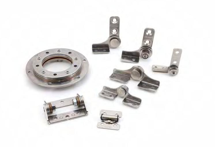
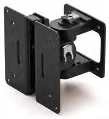
This mechanism holds a flap, lid, or cover in any position.
POSITION CONTROL HARDWARE
ONE WAY TORQUE HINGE (ADJUSTABLE)
Torque Direction
Direction]
Friction in one direction only. Torque strength adjustable. 2 versions available for friction torque opening direction (type – A) closing direction (type – B).
hinge Torque occurs in both upward and downward directions.
There is no torque in upward direction from 0° to 90°. Over 90°, a lid stopper is needed to hold the lid.
Generates torque in downward direction only. (Operation range: 0º ~ 180°)
The torque direction reverses when the hinge opens at over 90°. This allows a flap to hold in position at all angles of 180° with smooth and light operation.
Operating temperature: 32°F ~ 104°F (0°C ~ 40°C). Ideal for medical equipment, factory automation equipment, office automation equipment, workstation monitors.
° Torque will not occur in the upward direction at all angles of 180°.
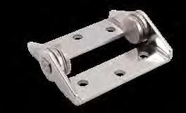
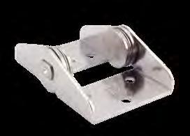
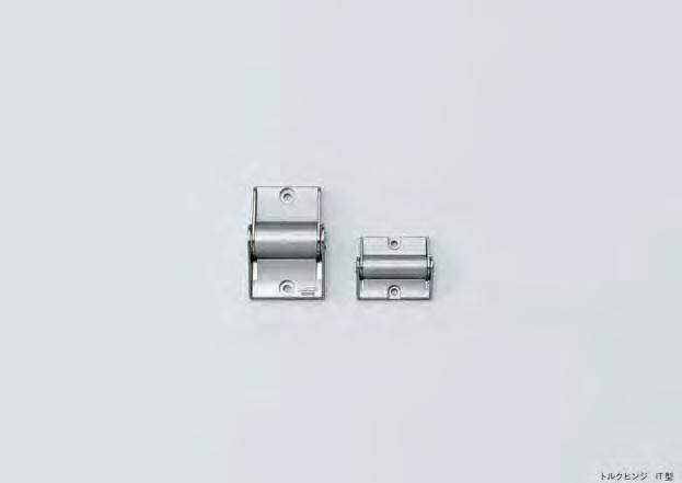
Hinge with friction for holding monitors, displays etc. in desired position.
Without torque available. (HG-ITSF, HG-ITMF)
Optional cover available for clean appearance.
3-5/32" (80 mm)
(66 mm)
(36 mm)

Body 304 Stainless SteelPolished
Shaft 303 Stainless SteelPlain
Washer Phosphor BronzePolished Spring Washer Steel Nickel
Cover ABS Silver
STAINLESS STEEL TORQUE HINGE
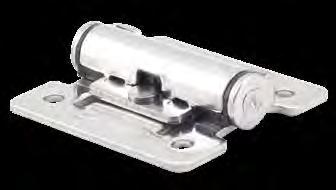
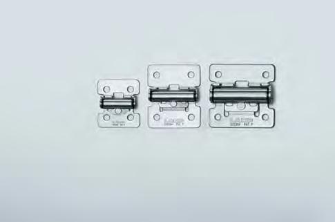
Hinge with friction torque holds lid/door in desired position. Stainless steel material ideal for harsh environments. Free stop between 0º ~ 180º. Successfully passed 20,000 open/close private cycle tests.
Note: Initial torque may var y - 20% ~ + 40%. At least 2 hinges necessar y for 1 door.
Body
Base
Fixing Tube
Fixing Tube
Stainless SteelPolished
Shaft303 Stainless Steel-
Press Washer
Pin
Stainless Steel Polished
STAINLESS STEEL TORQUE HINGE
(30)
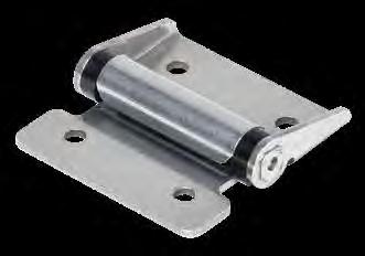
Hinge with friction torque holds lid/door in desired position. Stainless steel material ideal for harsh environments. Free stop between 0º ~ 180º.
Note:
At least 2 hinges necessar y for 1 door/lid. Operating temperature: 14°F ~ 104°F (-10°C ~ 40°C)
(30)
(50)
2” (50)2” (50) 1-1/4” (32) 2” (50) 2-15/16” (75) 2”(50)2”(50) 2-15/16” (75)
(30)
(65) 1-9/16” (40) 1-9/16” (40) (65)2-9/162-9/16” (65) 5/16”(8.5)5/16”(8.5)
(65)2-9/162-9/16” (65) 1-9/16” (40) 1-9/16” (40) (65)2-9/162-9/16” (65) 5/16”(8.5)5/16”(8.5) 11/16” (17)
SFTH STAINLESS STEEL TORQUE HINGE
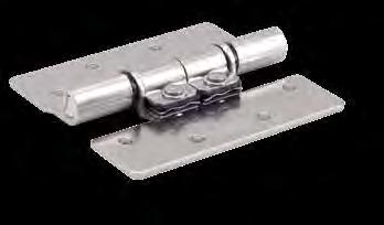
Hinge with friction torque holds lid/door in desired position. Stainless steel construction for corrosive environments. Operating temperature: -20˚C ~ 60˚C (-4˚F ~ 140˚F)
1-31/32 (26.5 mm) (50 mm) 1-37/64 (40 mm) 13/16 (20.8 mm) 33/64 (13 mm) 1-37/64 (40 mm) 25/32 (20 mm) 5/8 (16 mm) 1-43/64 (42.5 mm) 53/64 (21 mm) 33/64 (13 mm) 9/64 (3.5 mm) 17/32 (13.5 mm) (12.8 mm) 1/2 5/64 (2 mm)
9/32 (7 mm)
5/64 (2 mm) 5/32 (4 mm)
SFTH-03
SFTH-02-5 4.3 lbs·in (5 ±1kgf·cm)
SFTH-03-9 7.8 lbs·in (9 ±2kgf·cm) 51 30
SFTH-03-1916.5 lbs·in (19 ±2kgf·cm)
SFTH-05-3530.4 lbs·in (35 ±5kgf·cm) 195
(15 mm)
3-1/4
2-3/4 (82.5 mm) 1-41/64 (41.5 mm)
31/64 (12.5 mm) 19/32 (15 mm) (70
2-19/32 (66 mm) 1-21/32 (42 mm) 15/32 (12 mm) 55/64 (22 mm) 43/64(17 mm) 3/8(9.5 mm) 19/64 (7.5 mm) 15/32 (12 mm) 7/16 (11 mm) 3-35/64 (90 mm) 2-3/4 (70 mm) 1-3/4 (44.5 mm) 1-7/64
SFTH-05-5850.3 lbs·in (58 ±5kgf·cm) No.Part NameMaterial
➀ Body A 304 Stainless Steel Polished ➁ Shaft303 Stainless Steel ➂ Body B301 Stainless Steel
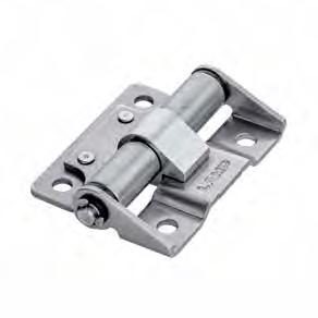
Two options for torque direction:
- Type A: has torque (free stop) in opening direction.
- Type B: has torque (free stop) in closing direction. Allows for frictionless handling of doors in opposite direction of torque.
Surface mounted: can be used horizontally or ver tically. Install a catch or latch to keep lids or doors from opening Durability: successfully passed 20,000 open/close private cycle test.
Ideal for medical or analytical equipment, automation devices, maintenance on various manufacturing equipment.
1-WAY CONCEALED TORQUE HINGE
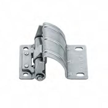
Two options for torque direction:
- Type A: has torque (free stop) in opening direction.
- Type B: has torque (free stop) in closing direction.
Allows for frictionless handling of doors in opposite direction of torque. Concealed hinge avoids tampering or exposure to external elements. Hinge is hidden (concealed) from the outside of the door. Can be used horizontally or ver tically.
Install a catch or latch to keep lids or doors from opening
Durability: successfully passed 20,000 open/close private cycle test. Ideal for medical or analytical equipment, automation devices, maintenance on various manufacturing equipment.
(42 mm) 2-9/32" (58 mm)
(16 mm)
(ø15 mm)
(27 mm)
shows torque direction.
the actual opening and closing angles in the Reference Dimensions.
HEAT RESISTANT TORQUE HINGE
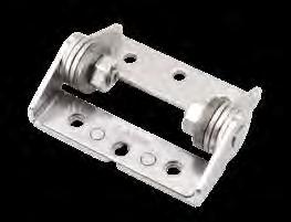
[Torque Transition] (in high temperature)
Suitable for use in heat-generating environments. Mounts externally to the machinery.
Operating temperature: 32ºF ~ 212ºF (0ºC ~ 100º C)
Recommended for dryers, lighting equipment, temperature chambers, food processing equipment. Ideal solution to replace spring hinges that cannot free stop at any angle
When installing, ensure that both hinge shafts are leveled and aligned.


Torque may decrease during and after heating, and it will restore when returning to normal temperature.
No.Part Name Material Finish
➀ Base L
➁ Base R
➂ Connecting Bracket
➃ Thrust PlateCarbon Steel
304 Stainless Steel -
➄ Movable Bracket304 Stainless Steel
➅ Ball Steel
➆ Spring WasherStainless Steel
➇ Hexagon Nut Steel Zinc Chromate (Trivalent)
➈ Shaft303 Stainless Steel -

LIFT-OFF TORQUE HINGE
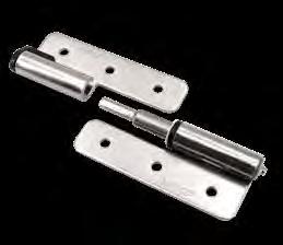
2.5 lbs·in (3.1 kgf·cm) ± 20%42
HG-KNT7LLeft 5.7 lbs·in (7.1 kgf·cm) ± 20%76
HG-KNT7RRight
HG-KNT16LLeft 13.0 lbs·in (16.3 kgf·cm) ±
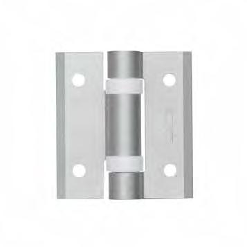
➀ BodyAluminum AloyAnodized
➁ Cap PolyacetalNatural
➂ Washer PTFE White
➃ Shaft303 Stainless Steel-
Hinge with friction torque lift off feature for easy removal. Can be used horizontally. Passed 20,000 open/close cycle tests.
➆ NutStainless Steel-
Retains the door at any angle. Plastic caps at rotating part prevent metal-to-metal friction and metal powder scattering. Can be used horizontally or vertically.
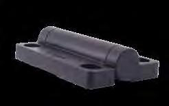
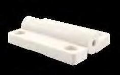
HG-VH8-OP-WT
HG-VH8-CL-BL
HG-VH8-T15-WT
HG-VH8-T35-WT *Increase of 0.16 kgf.cm for every 30° of rotation. Maximum rotation of
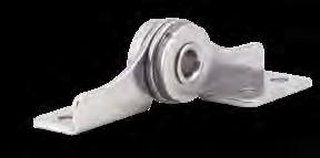
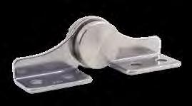
TORQUE HINGE (W/CABLE HOLE)
Washer430 Stainless Steel-
TORQUE HINGE
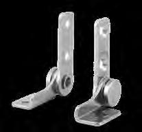
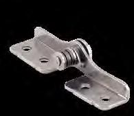
Hinge with built-in detent feature firmly keeps lid closed. No additional catch required. Suitable for corrosive environments.
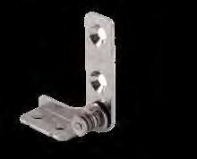
Hinge with built-in detent
STAINLESS STEEL TORQUE HINGE
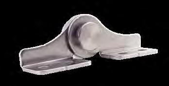
Torque hinge made entirely from stainless steel, making it suitable for use in cor rosive environments.
For pair use. When installing, ensure that both hinge shafts are leveled and aligned.
Operating temperature: 32°F ~ 104°F (0°C ~ 40°C).
Great for LCD, monitoring camera displays, medical and food equipment.
High Durability: HG-TAS passed 40,000 open/close private cycle test, twice that of HG-TA torque hinge (20,000 cycles).
Left-handed type shown. Right-handed type is symmetrical.
Example
ADJUSTABLE STAINLESS STEEL TORQUE HINGE
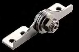
Torque adjustable from 0 ~ 4 N m (0 ~ 35.4 lbf in).
Factory setting is at 4.0 N m.
For pair use: Please use the same torque in both hinges. Use a spanner (nominal size 13) for torque adjustment. Do not forcibly remove the torque adjustment nut. When installing, ensure that both hinge shafts are leveled and aligned.
Torque hinge made entirely from stainless steel, making it suitable for use in cor rosive environments.
Operating temperature: 32°F ~ 104°F (0°C ~ 40°C).
Great for LCD's, monitoring camera displays, medical and food equipment.
High Durability: HG-TASJ40 passed 40,000 open/close private cycle test, twice that of HG-TA torque hinge (20,000 cycles).
Left-handed type shown. Right-handed type is symmetrical. Application Example
STAINLESS STEEL TORQUE HINGE
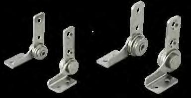
Marking: HG-TBS15…[15] HG-TBS25…[25]
(26 mm)
(16 mm)
(9.5 mm)
(8.5 mm)
Left-handed type shown. Right-handed type is symmetrical. HG-TBS15L, HG-TBS25L
(12 mm)
Torque hinge is made entirely from stainless steel, making it suitable for use in corrosive environments. For pair use. When installing, ensure that both hinge shafts are leveled and aligned.
Operating temperature: 0° ~ 40°C (32° ~ 104°F). Great for LCD's, monitoring camera displays, medical and food equipment.
High Durability: HG-TBS passed 40,000 open/close private cycle test, twice that of HG-TB torque hinge (20,000 cycles).
ADJUSTABLE STAINLESS STEEL TORQUE HINGE
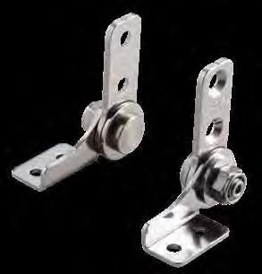
Torque adjustable from 0 ~ 4 N m (0 ~ 35.4 lbf in).
Factory setting is at 4.0 N m.
For pair use: Please use the same torque in both hinges. Use a spanner (nominal size 13) for torque adjustment. Do not forcibly remove the torque adjustment nut. When installing, ensure that both hinge shafts are leveled and aligned.
Torque hinge made entirely from stainless steel, making it suitable for use in cor rosive environments.
Operating temperature: 0° ~ 40°C (32° ~ 104°F).
Great for LCD's, monitoring camera displays, food and medical equipment.
High Durability: HG-TBSJ40 passed 40,000 open/close private cycle test, twice that of HG-TB torque hinge (20,000 cycles).
Left-handed type shown. Right-handed type is symmetrical.
(Unbalanced Load Type)
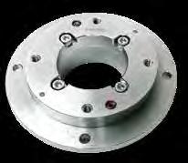
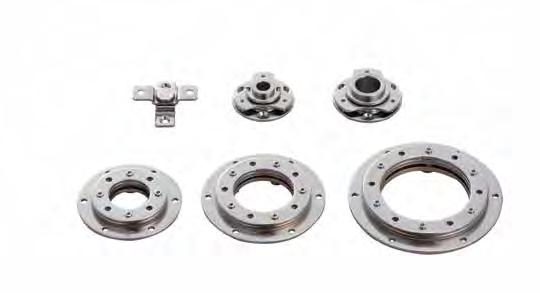
High rigidity swivel torque hinge supports unbalanced loads in a hanging installation.
Hinge can be installed vertically or horizontally.
Can rotate 360° and be held at any angle (free stop).
Rotation angle can be controlled with a supplied angle control bolt.
Center hole for easy cable management (2" opening diameter).
Durability: 30,000 open/close cycles passed (private test).


are 8 angle control screw holes at 45° intervals; the actual rotation angles are 6.8° narrower because the stopper pins are blocked by bolts.
2-13/64" (56 mm)
HG-S50-75
5-3/64" (128 mm)2-61/64" (75 mm)
Rotation angle: 360°
Free stop function, can hold in any desired position.
Design for easy wire pass through
Use for:
Industrial control panels and monitors
Note:
Initial torque may var y ±20%.
Do not lubricate. For indoor use only.
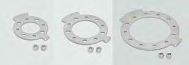
Plate and stopper form a set which can be installed to control the swivel angle of Swivel Torque Hinge HG-S. Two swivel directions and five angles can be selected according to the stopper installation position.
Includes:
HG-S-34-ARP: Height 6.2 mm/2 pcs
HG-S-50-ARP: Height 6.2 mm/2 pcs
HG-S-70-ARP: Height 7.2 mm/2 pcs (height differs from other models. Cannot be used together.)
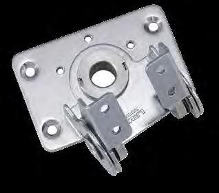
(62 mm) 2-63/64 (76 mm) 1-31/32 (50 mm) 1-3/16 (30 mm) 31/32 (24.5 mm) 37/64 (14.5 mm)
5/8 19/64 (7.5 mm) 1-3/16(30 mm) 45/64 (18 mm) 1-27/64 (36 mm) 35/64(14 mm) 15/64 (6 mm) (16 mm) (291-9/64mm)
TORQUE HINGE (DUAL AXIS)
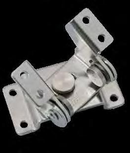
Dual Axis: Free stop between 0° ~ 200° (Tilting) and 360° (swiveling). Provides torque stability in both directions. Suitable for monitor screens. Successfully passed 20,000 open/close private cycle tests.
2-11/64 (55 mm) 13/64 1-49/64 (45 mm) 1-3/16 (30 mm) 15/32 (12 mm) (5 mm) 15/32 (12 mm) 33/64 (13 mm) 1-3/16 (30 mm) 9/32 (15 mm) 1-17/32 (39 mm) 1-31/32 (50 mm) 2-23/64 (60 mm) 25/32 (20 mm) 5/16 (8 mm) 55/64 (22 mm) (31/8mm) 5/64(2 mm) 25/64 (10 mm) 27/32 (21.5 mm) 2-1/32 (51.5 mm)
2-11/64 (55 mm) 13/64 1-49/64 (45 mm) 1-3/16 (30 mm) 15/32 (12 mm) (5 mm) 15/32 (12 mm) 33/64 (13 mm)
Tilt
Swivel
LIFT-ASSIS T TORQUE HINGE
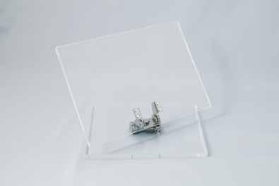
Featuring free stop with lift-assist for lid opening & closing directions (0º ~ 180°), giving full access to the inside of equipment. Lift-assist makes lid feel lighter to open and close.
This compact hinge is designed for external surface mounting on top- opening lids.
The retaining torque (0 ~ 31 lbs-in) is adjustable with a 3/8" (10 mm) socket or wrench.
Operating temperature: 32° ~ 104°F (0° ~ 40°C).
Cover (included) provides clean appearance to blend in with aesthetics of machinery
Durability: successfully passed 50,000 open/close cycle test (private). Ideal for medical, analytical and factory automation equipment. See Lid Size Guidelines graph for recommended range of supported lid height and lid weight.

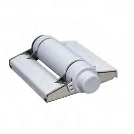
LIFT-ASSIST TORQUE HINGE
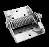
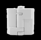
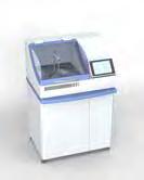
Featuring free stop with lift-assist for lid opening & closing directions (0º ~ 100°).
The retaining torque (0 ~ 31 lbs-in) is adjustable with a 3/8" (10 mm) socket or wrench.
Lift-assist, makes lid feel lighter to open and close. Operating temperature: 32° to 104°F (0° to 40°C).
This compact hinge is designed for external surface mount on top- opening lids.
High Durability: 50,000 open/close cycles passed (private test). Ideal for medical, analytical and factory automation equipment. Cover (sold separately) provides clean appearance to blend in with aesthetics of machinery.
Torque Adjustment A socket or wrench is needed (size: 10). 0 lbs·in is the factory preset.
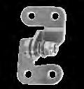
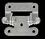
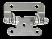
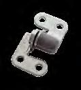
Cover Installation Dimensions
Mount covering the nut and bolt
Torque hinge that can be used for horizontal or vertical applications. Featuring free stop: holds lid or cover at any angle.
Durability: successfully passed 20,000 open/close private cycle tests.
Operating temperature 14ºF ~ 122ºF (-10ºC ~ 50ºC)
To be surface mounted externally (outside mount only).
Recommended for medical & analytical equipment, factory automation devices, acoustic equipment among other uses.
Designed for small, lightweight lids.
Cover (sold separately) hides the nut & bolt of the hinge.
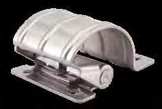
High torque and wide opening angle (130°).
Installation on the back side or inner side of the door for a clean aesthetics and appearance Can be used horizontally or ver tically. When installing, ensure that both hinge shafts are aligned. Successfully passed 20,000 open/close private cycle tests.
Note:
Initial torque may var y -20% ~ +40%. Not suitable for high frequency use. Do not lubricate
CONCEALED TORQUE HINGE
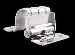
Installation on the back side of the door. Can be used both for horizontal and ver tical applications.
Note: Initial torque may var y -20% ~ +40%. Do not lubricate. For indoor use only.
Fixing Tube
lbs·in (3.6 kgf·cm)
lbs·in (7.1 kgf·cm)
HINGE
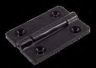
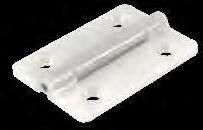
HG-MF15-WTWhite
HG-MF25-BLBlack 1-7/64" (28 mm) 45/64" (18 mm) 1-37/64" (40 mm) 63/64" (25 mm) 3/32" (2.5 mm) 2.00 lbs·in (2.5 kgf·cm) ± 33%
HG-MF25-WTWhite
TORQUE HINGE
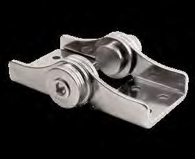
Free stop hinge in compact profile. Passed 20,000 open/close cycle tests.
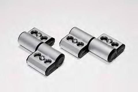
Friction in one direction only:
HG-TQA90-A: free rotation when turned counterclockwise, constant torque is applied when turned clockwise.
HG-TQA90-B: free rotation when turned clockwise, constant is applied when turned counterclockwise.
Note:
Initial torque may var y - 20% ~ + 40%. Not suited to vibration environment. Torque will be affected by temperature. Not suitable for high frequency use. Do not lubricate. For indoor use only. Installation
Summary of Movement No.Part NameMaterial
Body Aluminum Alloy Anodized ➁ Arm ShaftStainless SteelPlain
SleevePolyacetal (POM)Black
CoverPolyacetal (POM)Black
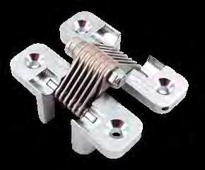
Hinge is completely concealed when the door is closed. Torque decreases as the opening angle increases, making easier to open the lid, refer to: Torque Range Chart.
Use with top-opening lids (opening angle 0°~100°) (free stop range).
Operating temperature: 32°F ~ 104°F (0°C ~ 40°C)
Application Example
Use with top-opening lids (opening angle 0
Installation
Screw
Screw
Bracket (spot welding)
Screws and brackets not included.
Rotation: 180°
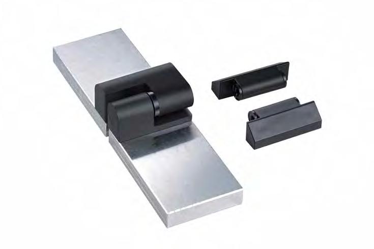
Friction in one direction only: Allows for frictionless handling of the door in the opposite direction. Hinges can be used in different situations(ex: Surface ner mount, concealed mount).
ck-Mount: There are no screw heads on the surface.
2-23/64" (60) 2-7/16" (62) 1-11/16 (43) 1-37/64"(40) 1-37/64"(40) 29/32" (23) 4×M6 49/64" (19.5)
➀ Bracket A Polyamide
➁ Bracket B
➂ Shaft 303 Stainless Steel
➃ Sleeve Polyacetal
➄ O-Ring Rubber
➅ One-Way Clutch Polyacetal
➆ Resin Washer Resin
➇ Bush Nut 304 Stainless Steel
➈ Cover Polyamide
Locus Chart
Torque Working Direction
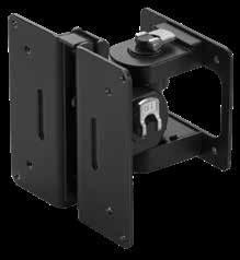
How to Install and Remove Monitor
Monitor easily attaches to bracket with slot and click.
To remove the monitor, press the release lever down and tilt the monitor out of the slot.
Auxiliary Lock Operation
How to Adjust Angle
Monitor can be easily installed and removed. Free stops in a range of 180º (swivel) and 40º (tilt).
Auxiliary lock prevents monitor from sagging due to minute vibration. Also suitable for touch screens
Bracket holes are based on VESA standard of 75 mm x 75 mm and 100 mm x 100 mm
For monitor sizes 12 ~ 22.9" weighing up to 22 lbs (10 kg)
Free stop feature allows you to freely tilt and swivel monitors and hold in the desired position.
Applications: LCD monitors for machine tools, OA equipment, medical equipment, etc.

Wire hole allows you to route wires through wire access opening.
Auxillary locks hold, tilt and swivel to a secure position. Release the lever to adjust the position.
Holds at any angle within 40º up/down tilt
Holds at any angle within 180º left/ right swivel
Monitor maintains position under vibration
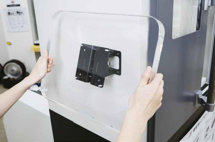
Stable Operation
No Wobbling
Prevents touch screens from shaking or causing unintentional inputs.
Auxiliary Lock Operation
1) Fit the protrusion into the groove of the bracket.
2) Push the lower part of the mounting plate.
Robust design holds monitors securely in position. Free stop feature allows you to freely tilt and swivel monitors and hold in desired position. Features an auxiliary lock mechanism which prevents sagging. Auxiliary lock protects monitor from unintended movement. VESA (75 mm x 75 mm adn 100 mm x 100 mm) compliant standard.
Supports 12" to 23" monitors weighing up to 22 lbs (10 kg) Applications: LCD monitors for machine tools, OA equipment, medical equipment, etc
Rotational Motion
The optional rotation bracket allows for free stop in the rotation direction. (Free-stop range: 95° on each side)
The auxilliary lock temporarily releases to avoid breakage if unintentional heavy load is applied to it.
*Do not forcibly move monitors when locked.
To remove, push down on the release lever and tilt the monitor.
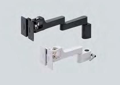
KA-T100S50-P2-WT
KA-T100S50-W3-BL
KA-T100S50-W2 Wall Mount / Single Arm
KA-T100S50-W3 Wall Mount / Double Arms
KA-T100S50-P2 Pipe Mount (ø30) / Single Arm
For wall mount type
Height Adjustment For pipe mount type Can be mounted on aluminium frame
KA-T100S50-P3 Pipe Mount (ø30)
Wiring Cables Comes with covers for cables
KA-T100S50-W2-BL Wall Mount/ Single Arm Black
KA-T100S50-W2-WT White
KA-T100S50-P2-BL Pipe Mount/ Single Arm Black KA-T100S50-P2-WT White
KA-T100S50-W3-BL Wall Mount/ Double Arms Black
KA-T100S50-W3-WT White
KA-T100S50-P3-BL Pipe Mount/ Double Arms Black KA-T100S50-P3-WT White No. Part
➀ Mounting Plate Steel (SPCC) Electrodeposition ➁ Body Steel (SPCC)/ ABS
Arm Aluminium Alloy/ ABS Matte Anodized ➃ Base Aluminium Alloy
(75 mm)
KA-T100S50-PMT-BL
(100 mm)
(75 mm)
KA-T100S50-PMT-WT
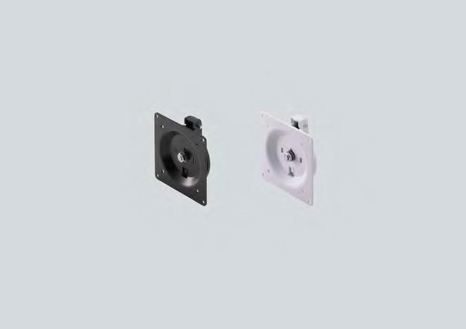

KA-T100S50-PMT-BL
Allows monitors to rotate and hold in position. Replace the original mounting plate (KA-T100S50) with this bracket. Compliant with VESA standard. (Hole patter n 75x75 mm, 100x100 mm).
Available monitor size: 12"-23" Max weight: 17.6 lbs. (8 kg)
Free-stop Rotation
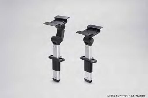
Tilt angle can be adjusted in 10° increments while the button is pressed. The back lever allows for height adjustment in 1" (25 mm) increments (4 levels). eatures a friction mechanism which prevents against accidental release. Applicable monitor size: 12" - 22.9" (304.8 mm - 581.7 mm) Weight: Max. 22 lbs (10 kg) Monitor mounting holes VESA compliant (75
KA-TLG2-100KA-TLG1-100
➁ Mounting PlateSteel (SPHC)
➀ BracketPolyamide (PA) Black
➂ Cover Polycarbonate
➃ Outer Pipe ABS
➄ Aluminium Pipe Aluminium Alloy Anodized
➅ End Cap ABS Black
➆ ButtonPolyamide (PA) Grey
➇ Button ABS
➈ Cross-recessed trus head screw SteelBlack Chromate
PackingNitrile Rubber (NBR)Black
KA-TLG2-100
TORQUE LID STAY (FREE STOP)
Friction torque lid stay holds lid open at any position along its range of motion.
Friction torque in one-way direction only.
Torque strength adjustable
Handed: specific left and right hand mounting. Can be used individually or in pairs
Torque Calculation: - Torque = Door Height x 1/2 x Door Weight
Opening Direction Feature Torque
No friction when opening
One-Way Torque
DownwardUpward Free Stop Stop at any angle
No.Part NameMaterialFinish/Color
Cover
Arm A
Arm B
Body Zinc Alloy Nickel
Adjustment screw
Mounting Plate
Fix Screw
TORQUE LID STAY (FREE STOP) TORQUE LID STAY (FREE
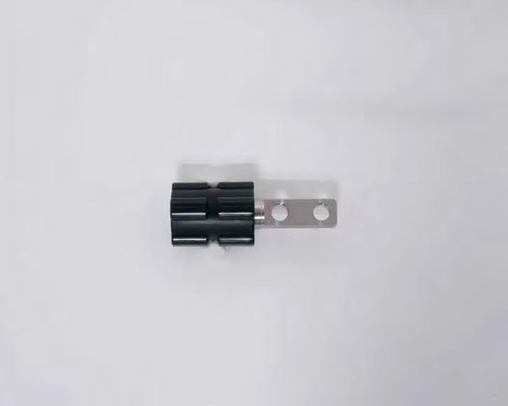
Greaseless Torque Hinge.
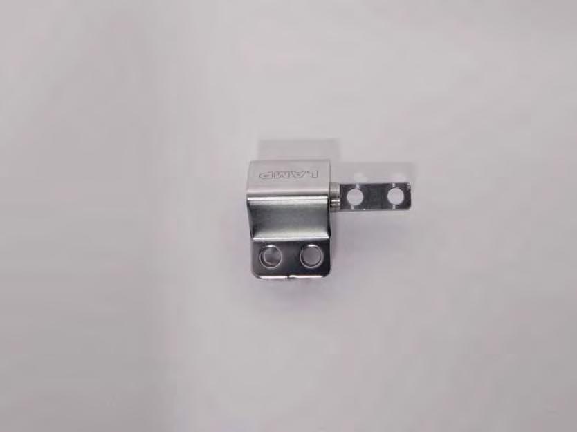
Torque Hinge.
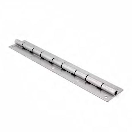
TORQUE PIANO HINGE
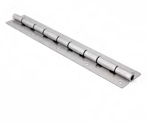
Unique long type torque piano hinge. Free stop function maintains a safer working environment
Reduces gaps between housing and doors for industrial equipment and shopfittings to improve security and reduce danger
Greaseless hinge allows for water-drop level exposure
Can be used in multiples for doors larger than 12" Sucessfully passed 30,000 private cycle tests for vertical and horizontal applications
For opening/closing of maintenance machine doors.

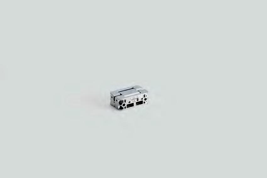
Movement
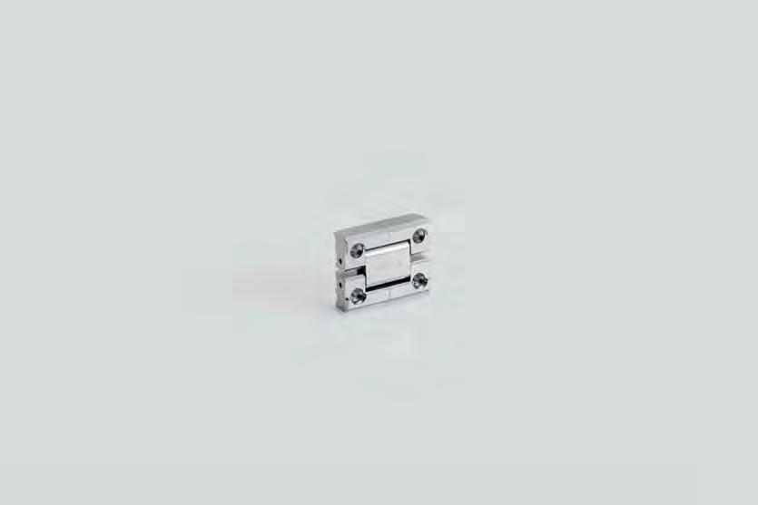
Standard concealed hinge
Hinge with same torque on both sides
Application Example

Shown in folded position.

Lays flat so shafts do not protrude.
No visible screw holes when surface is extended
Hinge Movement
No.Part NameMaterialFinish/Color
Main BodyB
Main BodyA Zinc Alloy Chrome, Satin Nickel, Black
Intermediate Body
Sleeve Plastic (PBT) Black
Bumper
HG-TMH
Silent and safe Soft Motion
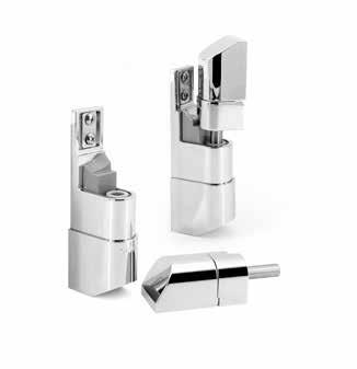
Slows the speed of doors, lids, or drawers during closing and opening for quieter, safer operation. ELIMINATES SLAMMING NOISE
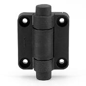
SOFT-CLOSE DAMPENING HINGE
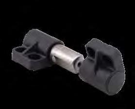
*A-type damper: Damper works counterclockwise.
*B-type damper: Damper works clockwise.
*Sold in pairs. (Each of A/B type)
Hinge with built-in damper to keep lid from slamming. Torque calculation: Torque = Door Height x 1/2 Door Weight. Passed 70,000 open/close cycle tests.
Soft-Close damper keeps lid from slamming shut. Surface mount type.
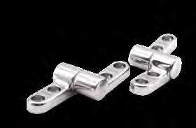
HINGE
~ 124 lbs·in (102 ~ 143 kgf·cm) HG-JHWG5053 ~ 88 lbs·in (61 ~ 102 kgf·cm) HG-JHWG7088 ~ 124 lbs·in (102 ~ 143 kgf·cm)
Soft-Close damper keeps lid from slamming shut.
Surface mount type.
Operating temperature: 0 ~ 40˚C (32 ~ 104˚F)
Operating angle: 115º/Angular allowance 5º Sold in pairs
Soft-Close damper keeps lid from slamming shut. Surface mount type. Two different damper direction available for various application.
NameMaterial Color
Bracket PBT Plastic/Zinc Alloy Dark Grey ➁ Cap Polypropylene
Damper304 Stainless SteelPlain
(W/Damper) (W/Detent only)
(18 mm) 1-17/64 (32 mm) 3-5/32 (80 mm)
HG-CSH63 DETENT HINGE (WITH or WITHOUT DAMPER)
Detent hinge with built-in damper as an option.
Detent will hold lid in open/closed position without secondary suppor t, and optional damper will provide soft closing.
Operating angle: 100º (Detent at both 0º and 100º)
Detent holding force: 8.8 lbs·in (10.2 kgf·cm)
Damper torque range per piece: 9 ~ 22 lbs·in (10.2 ~ 25.5 kgf·cm)
(18 mm)
3-5/32 (80 mm) 1-17/64 45/64 45/64 (18 mm) (18 mm) (32 mm) (63 mm) 2-31/64 (40 mm) 1-37/64 HG-CSH63 45/64
HG-CSH63 (W/Detent only) (W/Damper)
DISK DAMPER
Disc-shaped damper gently closes lid without slamming shut. Narrow profile for unobtrusive installation.
Suitable for food service environments.
Successfully passed 30,000 open/close private cycle test.
Operating temperature: 5 ~ 35ºC (41 ~ 95ºF)
Spacer and installation screws are not included, and var y with application. Please contact customer service for more information.
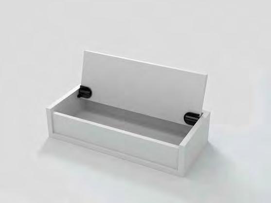
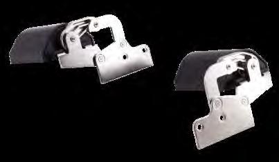
Hinge with damper built-in to keep lid from slamming shut.
Mortise mount type.
Ideal for small size lid.
Sold in pairs
Torque Calculation:
Torque = Door Height × 1/2 × Door Weight
• Please see diagram below for applicable torque moment.
• Please specify face plate color when ordering.
• Please install Left and Right Brackets on correct side.
Smaller type HG-JHM16 available
Suitable for use in vanity cases, electronics panels in tables, computer terminals for reception desks, etc.
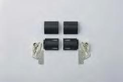
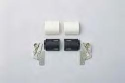
* Right-handed type shown. Left-handed type is symmetrical. Top-opening
* Gap is decreased compared with standard when chamfered.
Hinge Plate Installation Position
Surface mount type: Easy to install without the need of recessing Hinge with built-in UDH damper.
Soft-close and smooth-open features.
For Inset Lid.
Cover hides mounting screws.
Sold in pairs
Below torque range is the value when using a pair of hinges (left and right) per lid.
When installing, ensure that both hinge shafts are levelled and aligned. Damper mechanism engages after being opened at 60º or more.
Damper wor king direction
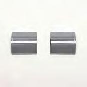
Door Weight Selection
Calculation of maximum door moment (for homogeneous material)
T = × 9.80665 × L ×
T : Max. door torque (N·m) : Door weight (kg)
L : Distance from rotation centre to door centre of gravity (mm) L = – A
For heterogeneous door (e.g., attached with a mirror), please contact our technical support (support@sugatsune.com) for assistance.
for assuming that the centre of gravity is in the centre of door)
No.Part NameMaterial Finish
Hinge Plate Sttel/Zinc Alloy Nickel
Bracket POM Black
Cover ABS Black/White/ Chrome
Damper
lid closed Top-opening lid opened by 90˚
Front View
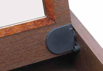
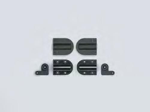
Hinge with damper built-in to keep lid from slamming shut.
Mortise mount type.
Ideal for small size lid.
Sold in pairs
Torque Calculation:
Torque = Door Height × 1/2 × Door Weight
• Please see diagram below for applicable torque moment.
• Please specify color of face plate (sold separately) when ordering
• Please install Left and Right brackets on correct side
Bracket/Mounting Plate 1-49/64" (45 mm) 1/8" (3 mm)
5/8" (16 mm) 25/32" (20 mm)
25/32" (20 mm)
5/8" (16 mm)
7/32" (5.5 mm) 1-31/32" (50 mm)
(45 mm) 1/8" (3 mm)
HG-JHM16-50 29.5 ~ 43.4 lbs·in (34 ~ 50 kgf·cm)
HG-JHM16-34 BodyBlack 17.4 ~ 29.5 lbs·in (20 ~ 34 kgf·cm) 91/pair 10 pairs 120 pairs
HG-JHM16-BL Cover Black - 12/pair
HG-JHM16-WT White
7/32" (5.5 mm) 1-31/32" (50 mm) 2-1/8" (54 mm)
2-1/8" (54 mm)
No.Part Name MaterialColor
➀ Mounting PlateAluminum Black
➁ Damper BracketPolyacetal
➂ Face Plate ABS White, Black
➃ Damper304 Stainless SteelPlain
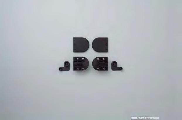
Black cover White cover
SOFT-CLOSE DAMPENING HINGE
Damping direction
Top-Opening Upward Downward Trapdoor
HG-JHM9-S-BL Black Side Panel
HG-JHM9-S-WT White
HG-JHM9-U-BL Black Under Panel Mount
HG-JHM9-U-WTWhite
SOFT-CLOSE DAMPENING HINGE
Hinge with damper built-in to keep lid from slamming shut. Surface mounts into the lid. Side panel or under panel mounted. Sold as a set.

Mounting Plate R PBT plastic
Mounting Plate L
Damper Polyacetal
HG-JHM14
Hinge with built-in damper to keep lid from slamming shut. Mortise mount type.
Bracket
➁ Mounting Plate R PBT
Mounting Plate L ➃ Face PlateABS
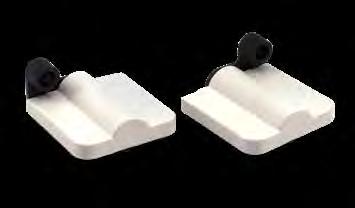
Small damper hinge with self-opening function for topopening lids. Using with a touch latch enables pop-up function of the lid.
Inset type. Opening speed is adjustable with a hex key. Cover hides mounting screws for clean appearance. Easy to cut out with a router. Applicable into surface mount with Bracket UKZ11-BL (sold separately).
(16
*t= 5/8" (16 mm).
Prepare more than 1 for Gap B of Opening clearance.
Cross-section Drawing
Surface Mount Type (Installed with Bracket for Surface Mount UKZ11-BL) 1-7/8" (47 mm) 5/16" (8.5 mm) at Min. 1/2" (12.5 mm)
Top View
Bracket Installation
Cut Out Dimensions t+ 3 9/16" (13.6 mm) 5/8" (16 mm)
Hinge
HG-JHM11-1BL Black
HG-JHM11-1WT White
0.44 ~ 0.89 lbs·in (0.51 ~ 1.02 kgf·cm)
HG-JHM11-2BL Black 0.89 ~ 1.77 lbs·in (1.02 ~ 2.04 kgf·cm)
HG-JHM11-2WT White
HG-JHM11-3BL Black 1.77 ~ 2.57 lbs·in (2.04 ~ 2.96 kgf·cm)
HG-JHM11-3WT White
HG-JHM11-4BL Black 2.57 ~ 3.54 lbs·in (2.96 ~ 4.08 kgf·cm)
HG-JHM11-4WT White
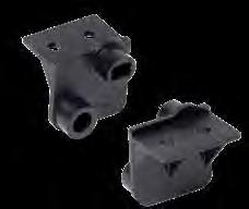
Bracket for Surface Mount
3/8" (9 mm) Stopper
Rotation Center 3 1/8" (3 mm)
SELF-OPEN DAMPER HINGE
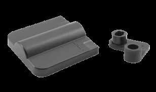
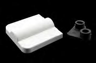
Installation
Self-open movement
Cross-section Drawing
Small damper hinge with self-opening function for top-opening lids. Using with a touch latch enables pop-up function of the lid. Inset type.
Opening speed is adjustable with a hex key..
Cover hides mounting screws for clean appearance.
Easy to cut out with a router.
Applicable into surface mount with Bracket UKZ11-BL (sold separately).
Calculation of maximum door moment
T= m × 9.80665 × L
T:Max. door torque (N/mm)
m:Door weight (kg)
L:Distance from rotation centre to door centre of gravity (mm) L= − A( Formula for assuming that the centre of gravity is in the centre of door)
D:Door length (mm)
A:Bracket installation dimension (mm)
[Example] D=180 mm 、 A=26 mm 、 m=0.63kg
T=0.63×9.80665×( −26) =395(mN・m) =0.395 (N m)
(3
(2 mm)
moreB=Openingclearance, than1
1/8" (3 mm) t L m 17/32" (13.6 mm) A= 1-1/32" (26 mm)
*t= 5/8" (16 mm). Prepare more than 1 for Gap B of Opening clearance. 5/8" (16 mm)
Installation
Top View When closed door Bracket
Drawing

(9 mm)
(29 mm)
(14 mm) 29/32" (23 mm)
W=Cabinet inside width- 15/64" (6 mm)
(9 mm)
ONE WAY DAMPER TORQUE HINGE (Adjustable)
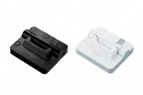
Torque hinge with damper.
The torque adjustment feature enables lids and doors to stop at any position during opening or closing.
Torque is generated in one direction. Almost no reverse torque is generated, allowing for smooth operation.
Cycle tested for 20,000 cycles.
Integrated stop design eliminates the need for a lid stop.
Covers Integrated Stopper Design
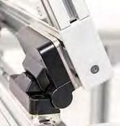
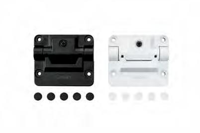
Cover hides threads without compromising design.
Mounting Specification Mark
A:External Topside Mounting B:Internal Mounting and Backplate
Mounting Possibilites
Outside Back MountTop Mount
HG-TQJD50-B with Internal Mounting and Backplate
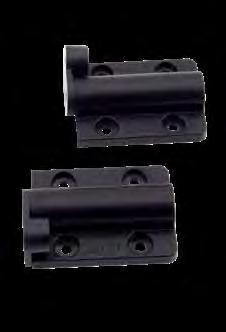
HG-JHS9-S-WT White
HG-JHS9-U-BL Black Under Panel Mount
HG-JHS9-U-WT White
Soft opening hinge, push latch sold separetely. Built in damper for soft opening. Sold as a set. For inset applications. 105º opening angle.

HG-JHS9-U
HG-JHS9-U
HG-JHS9-S
HG-JHS9-S
ROTARY DAMPER


Tube design for concealed application. For inset applications.


Plate (Sold Separately) Catch with built-in damper, closes doors smoothly.
Slim design suitable for various inset and overlay door installations.
Available for both wood and glass cabinet doors. Glass face plate SDS-50G sold separately Includes screws.
Non-handed: can be installed on left or right side.
DC-100
UDH-14 Type

UDH Type
UDH-16 Type
UDH-16N Type
TORQUE DAMPER
UDH-14 Type
➀ Body 304 Stainless Steel Plain
➁ Shaft PBT Plastic A-White, B-Grey ➂ Cover Ring
UDH-16N Type
➀
UDH-14ALS
UDH-14AMS
Clockwise
UDH Type
UDH-AGS 30.0 ~ 34.0 lbs·in (35.0 ~ 40.0 kgf·cm)
UDH-16AMS
~ 17.3 kgf·cm)
UDH-16AHS 15.0 ~ 22.0 lbs·in (17.3 ~ 25.5 kgf·cm)
UDH-16N AMS
Clockwise
Clockwise
Clockwise
~ 21.2 lbs·in (17.3 ~ 24.5 kgf·cm)
~ 30.6 kgf·cm)
Clockwise
Keeps lids/doors from slamming shut. Patented technology that allows a small design to produce high torque and wider dampening angles Stainless steel body keeps dampening torque stable and consistent.
Ensures high durability and ideal for corrosive environments.
Cycle tested at 70,000 for natural closing and 13,000 forced closing
Body 304 Stainless Steel Plain
Shaft PBT Plastic A-White, B-Grey
Cover Ring304 Stainless Steel
UDH-16 Type
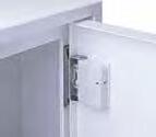
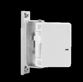
Soft and self-closing hinge ensures quiet, safe door closure
Automatically and slowly closes doors from 35º. The hinge will be hidden from view (concealed) when the door is closed.
Adjustable closing speed (with hex key). Allows precise, machine-friendly door movement. Firmly holds door closed to prevent gaps, so that machines continue to operate without interruption. Internally-mounted hinge is ideal for tamper-proof security cabinets (medical and pharmaceutical industr y).
Passed 50,000 open/close private cycle test.
Note:
Door stopper can be set to prevent from opening over 95°.
Operating temperature: 32 ~ 104ºF (0 ~ 40ºC). Do not lubricate. For indoor use only.
No.Part NameMaterialFinish
➀ Body A Polyamide (PA) Light Grey
➁ Body B
➂ Body CoverPolyacetal (POM)
➃ Press Arm 304 Stainless SteelPlain
➄ Shaft Steel Nickel
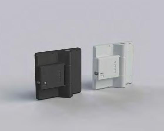
Soft and self-closing hinge ensures quiet, safe door closure
Adjustable closing speed (with hex key). Allows precise, machine-friendly door movement. Firmly holds door closed to prevent gaps, so that machines continue to operate without inter ruption.
Surface-mounted hinge saves internal machine space and helps maintain cleanliness (ideal for food equipment and medical industry). Can be installed on aluminum frames for machine equipment.
Passed 50,000 cycle test (private).
Note:
Stoppers recommended to prevent door from over-extending past 180° opening. Not suitable for vibrational applications/ environments
Operating temperature: 32 ~ 104ºF (0 ~ 40ºC). Do not lubricate. For indoor use only.
No.Part NameMaterial Finish
➀ Body A Polyamide (PA) Black, Light Grey
➁ Body BSteel
➂ Shaft Brass Nickel
➃ Screw CoverPolyacetal (POM)Black, Light Grey
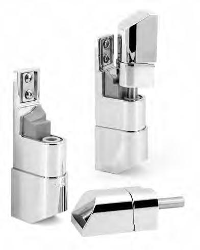
Soft-close Hinge (for upper)
Hinge]
Soft-Close Hinge
Hinge]
(102 mm)
(150 mm)
(102 mm)
(13 mm) (rise)
(49.6 mm)
* Left-handed type is shown.
Hinge]
Self-close Hinge (for lower)
Lift-off hinges for easy installation and removal of a door. Automatically and quietly closes the doors without additional dampers or door closers.
Sold in pairs/sets that includes a self-closing hinge and a soft-closing hinge.
Automatically closes doors from its 65º open angle and features an adjustable damper to control the closing speed. The self-close function helps reduce the loss of energy by keeping doors shut for common applications such as cold storage equipment, laboratories, and food warmers. Includes covers to hide the mounting screws.
Angled surface of covers designed to prevent dust and other particles to accumulate.
Door position can be adjusted for depth and in a horizontal direction 1/8” (± 3 mm).
Durability: passed 50,000 open/close cycles (private test).
Covers
Self-Close Hinge
[Adjustment Plate]
(102 mm)
(102 mm)
(13 mm) (rise)
Plate
HEAVY DUTY SOFT-DOWN STAY
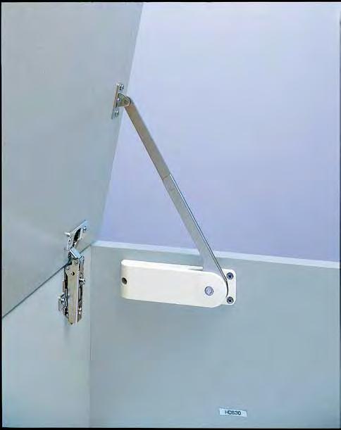
For TOP-OPENING FLAP DOOR with concealed, piano, butt or concealed hinges. Used in pairs
HDS-20 is designed to hold door in fully opened position.
Handed: Specific left and right hand mounting.
Torque Calculation:
Torque = Door Height x 1/2 x Door Weight
- K-Type (Light Duty): 121 ~ 173 lbs·inch (140 ~ 200kg·cm)/pair
- M-Type (Medium Duty): 173 ~ 216 lbs·inch (200 ~ 250 kg·cm)/pair
- H-Type (Heavy Duty): 216 ~ 260 lbs·inch (250 ~ 300 kg·cm)/pair
Inset Use
1-13/16 (46 mm)
4-27/64 (112.5 mm) 1-49/64 (45 mm)
4-9/64 (105 mm) 4-27/64 (112.5 mm) 1-49/64 (45 mm) 5-15/16 (151 mm) 6-49/64 (172 mm) 7-63/64 (203 mm) 11-17/64 (286 mm) 1-13/16 (46
4-9/64 (105 mm)
5-15/16 (151 mm)
6-49/64 (172 mm)
7-63/64 (203 mm) 11-17/64 (286 mm)
1-1/16 (27 mm)
(27
SELF OPENING STAY
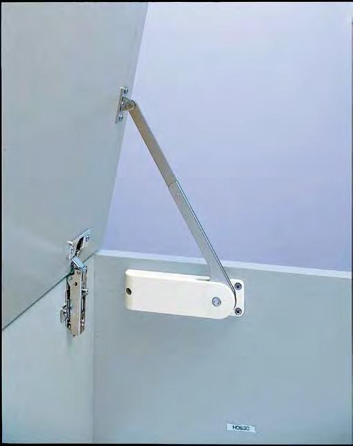
Lid will self open past the free stop angle For TOP-OPENING FLAP DOOR with piano, butt or concealed hinges. HDS-20S is designed to hold door in fully opened position. Used in pairs
Torque Calculation:
Torque = Door Height × 1/2 × Door Weight
H-Type: 61 ~ 95 lbs·in (70 ~ 110 kg·cm)/pair
S-Type: 96 ~ 130 lbs·in (111 ~ 150 kg·cm)/pair
230-26/19T
230-P4W-32T (Sold separately)
HDS-20S-HR-WT
With Piano/Butt Hinge With Concealed Hinge
With Piano/Butt Hinge With Concealed Hinge
With Piano/Butt Hinge
1-7/64
1-7/64
63/64 (25 mm)
49/64 (19.5 mm)
With Concealed Hinge
63/64 (25 mm)
49/64 (19.5 mm)
(32 mm)
1-29/32 (32 mm)
6-23/32 (170.5 mm) (48.5 mm)
6-23/32 (170.5 mm) (48.5 mm)
1-29/3 2 (32 mm)
1-37/64 (40 mm)
1-37/64 (40 mm)
4-9/64 (105 mm)
4-27/64 (112.5 mm)
6-27/64 (163 mm) 11-57/64 (302 mm)
1-7/64 (28 mm) 1-1/16 (27 mm) 53/64 (21 mm) 2-3/4(70 mm) 27/32 (21.5 mm)
6-27/64 (163 mm) 11-57/64 (302 mm) 4-27/64 (112.5 mm) 4-9/64 (105 mm) 1-7/64 (28 mm) 1-1/16 (27 mm) 53/64 (21 mm) 2-3/4(70 mm) 27/32 (21.5
1-29/32 (48.5 mm)
1-29/32 (48.5 mm)
3/4 (19 mm) 1-37/64(40 mm)
6-59/64 (176 mm)
6-59/64 (176 mm)
(70 mm) 12-3/32 (307 mm) 6-39/64 (168 mm) 3/4 (19 mm) 1-37/64(40 mm)
4-9/64 (105 mm) 1-7/64(28 mm)
4-27/64 (112.5 mm)
4-9/64 (105 mm) 1-7/64(28 mm)
4-27/64 (112.5 mm)
53/64 (21 mm) 1-1/16 (27 mm)
6-39/64 (168 mm)
12-3/32 (307 mm)
53/64 (21 mm) 1-1/16 (27 mm)
(70
27/32 (21.5 mm)
(21.5
HDS-20S/HL-WTHDS-20S/HR-WT
HDS-20S/HL-BLHDS-20S/HR-BL H61 ~ 87 lbs·in (70 ~ 110 kg·cm) 30040200
HDS-20S/SL-BLHDS-20S/SR-BL S96 ~ 130 lbs·in (111 ~ 150 kg·cm)
HDS-20S/SL-WTHDS-20S/SR-WT
DUTY SOFT-DOWN STAY
With Piano/Butt Hinge
For DOWNWARD-OPENING FLAP DOOR with concealed, piano, butt or drop hinges. HDS-10 is designed to hold door in closed and opened positions
Used in pairs
Handed: Specific left and right hand mounting.
Torque Calculation:
- Torque = Door Height x 1/2 x Door Weight
- K-Type (Light Duty): 121 ~ 173 lbs·inch (140 ~ 200 kg·cm)/pair
- M-Type (Medium Duty): 173 ~ 216 lbs·inch (200 ~ 250 kg·cm)/pair
- H-Type (Heavy Duty): 216 ~ 260 lbs·inch (250 ~ 300 kg·cm)/pair
Self & Soft Close, Door Opening, Catch position Dimensions from left to right: S= overlay, 152, 26, 40, 1, 35, 153+s, 32, 19.5, 25.
With Drop Hinge (SDH-001)
HDS-10S-KR/BL
SDH-001 (Sold separately)
HDS-10S-KL/BL
HDS-10S-KL/WT
HDS-10S-ML/BL
HDS-10S-K-BL
HDS-10S-K-WT
HDS-10S-M-BL
HDS-10S-M-WT
HDS-10S-H-BL
HDS-10S-H-WT
HDS-10S-S-BL
HDS-10S-S-WT
HDS-10S-KR/BL
HDS-10S-KR/WT
HDS-10S-MR/BL
52.2 ~82.6 lbs·in (60 ~ 95 kgf·cm)
~ 113.0 lbs·in (95 ~ 130 kgf·cm)
~ 139.0 lbs·in (110 ~ 160 kgf·cm)
~ 156.5 lbs·in (140 ~ 180 kgf·cm)
For DOWNWARD-OPENING FLAP DOOR with piano, butt or drop hinges When pushed to close, HDS-10S is designed to self close and soft close
Used in pairs
Torque Calculation:
Torque = Door Height × 1/2 × Door Weight
K-Type: 60 ~ 95 kgf.cm(52 ~ 82 Ibs. Inch)/ pair
M-Type: 95 ~ 130 kgf.cm(82 ~ 112 Ibs. Inch)/ pair
H-Type: 110 ~ 160 kgf.cm(95 ~ 138 Ibs. Inch)/ pair
S-Type: 140 ~ 180 kgf.cm(121 ~ 156 Ibs. Inch)/ pair
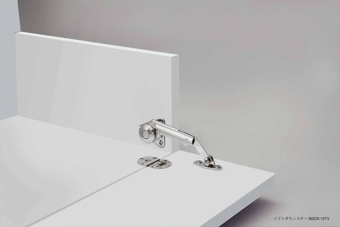
For DOWNWARD-OPENING FLAP DOOR with concealed, piano, butt or drop hinges. Short arm type designed for shorter door height applications
Handed: Specific left and right hand mounting
Torque Calculation:
-
Drop Hinge
Single Knuckle Hinge
For DOWNWARD-OPENING FLAP DOOR with concealed, piano, butt or drop hinges.
(89 mm)
1-17/64 (22 mm)
4-17/32 (115 mm) 3-57/64 (99 mm)
mm) (32 mm) 1-9/64 (29 mm) 5/8 (16 mm) 29/32 (23 mm)
(90 mm)
(32 mm)
This drawing shows NSDX-10RK (Right-hand side mounting). NSDX-10LK (left-hand) is symmetrical.
NSDX-10 is designed to hold door in closed position. Speed adjustment screw located on front for easy adjustment.
Handed: Specific left and right hand mounting.
Torque Calculation:
- Torque = Door Height x 1/2 x Door Weight
- Per Piece: 19 ~ 60 lbs·inch (20 ~ 70 kg·cm)
- Per Pair: 38 ~ 120 lbs·inch (40 ~ 140 kg·cm)
Short-arm version (NSDX-10(R/L)K/TV) for shorter door height available. 3.5×15
Arm Mounting Plate
90˚ Opening Soft-open
SOFT-DOWN STAY (SHORT-ARM)
SDH-001 (Sold separately)
2-9/16
3-31/32 (101 mm) 2-7/16 (62 mm) 1-15/64 (31.5 mm) (65 mm)
2-7/16 (62 mm) + S W/ Drop Hinge W/ Single Knuckle Hinge 2-7/8 (73 mm) 1-59/64 (49 mm) + S W/ Drop Hinge 2-23/64 (60 mm) W/ Single Knuckle Hinge
S=Overlay Coverage in case of drop hinge
SDS-100W-TV W/O Catch White
SDS-100B-TV Black
SDS-C100W-TV With Catch White
SDS-C100B-TV Black
SDS-100W-TVZ W/O Catch White
SDS-100B-TVZ Black
SDS-C100W-TVZ With Catch White
SDS-C100B-TVZ Black
(19.5 mm)
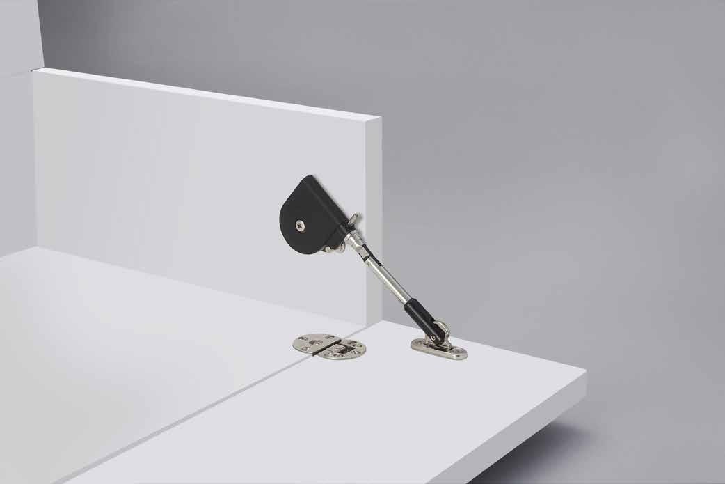
For DOWNWARD-OPENING FLAP DOOR with concealed, piano, butt or drop hinges. Short arm type designed for shorter door height applications
SDS-C100TV has a catch to hold the lid in closed position.
SDS-100TV does not have catch feature. Designed to be used with magnetic catch or touch latch. Non-handed: Can be installed on left or right side. Torque Calculation: - Torque = Door Height x 1/2 x Door Weight
Mounting Plate SDS-A
SDS-C100 SOFT-DOWN STAY
For DOWNWARD-OPENING FLAP DOOR with concealed, piano, butt or drop hinges. SDS-C100 (with catch) is designed to hold door in closed position.
Non-handed: Can be installed on left or right side.
Torque Calculation:
- Torque = Door Height x 1/2 x Door Weight
- Per Piece: 30 ~ 43 lbs·inch (35 ~ 50 kg·cm)
Recommended Door Thickness: 25/32" (20 mm) Short-arm version SDS-100TV (or C100TV) for smaller door height available.
Mounting Plate SDS-A
8-55/64 (225 mm): Drop Hinge
8-37/64 (218 mm): Single Knuckle Hinge
5-19/32 (142 mm): Drop Hinge Side Board
5-5/16 (135 mm): Single Knuckle Hinge
3-21/64 (84.4 mm)
21/32 (16.5 mm) 1-17/64
4-7/32 (107 mm): Drop Hinge
3-15/16 (100 mm) Single Knuckle Hinge (32 mm)
49/64 (19.5 mm) 13/32 (10.5 mm) 1-49/64 (45 mm)
HEAVY DUTY SOFT-DOWN STAY
For UPWARD-OPENING FLAP DOOR with concealed hinges.
Used in pairs
HDSN-30 is designed to hold door in closed and opened position.
Handed: Specific left and right hand mounting.
Torque Calculation:
- Torque = Door Height x 1/2 x Door Weight
- In case of opening angle 90º
- K-Type (Light Duty): 122 ~ 155 lbs·in (140 ~ 179 kg·cm)/pair
- M-Type (Medium Duty):
156 ~ 190 lbs in (180 ~ 219 kg cm)/pair
- H-Type (Heavy Duty): 191 ~ 225 lbs in (220 ~ 259 kg cm)/pair
- S-Type (Super Heavy Duty): 226 ~ 260 lbs in (260 ~ 300 kg cm)/pair
Dimensions are for 90° opening, solid wood or 45mm width aluminum frame door. For 80° opening, please use the figures in ( ). Fig.1 and Fig. 2 show the dimensions for 20 mm width aluminum frame door using mounting plate HDSN-AZ. Recommended concealed hinge is overlay/105° opening/free swing type.
Finish/Color
Arm Mounting Plate (Sold separately, please specify when ordering.)
HDSN-30HR
HDSN-30SL HDSN-30SR S226 ~ 260 lbs·in (260 ~
With Single Knuckle Hinge With Concealed Hinge
For UPWARD-OPENING FLAP DOOR used with piano, butt or concealed Hinges. Used in pairs
HDS-30 is designed to securely latch a flap closed and hold it in the fully opened position.
Torque Calculation:
- Torque = Door Height × 1/2 × Door Weight
- K-Type (Light Duty):
- M-Type (Medium Duty):
- H-Type (Heavy Duty):
coverage by concealed hinge
S=Overlay
■ Installation With drop hinge
Soft-down stay for (DOWNWARD-OPENING FLAP DOORS) with piano, butt, or drop hinge (SDH-001).
Easy to install by aligning the body to the edge of a cabinet.
Designed for smaller cabinet doors in media centers or TV consoles. Opening speed adjustable. The adjustment screw located on back for clean appearance.
Easy to close.
Holds lid in closed position.
Torque Calculation:
Torque = Door Height × 1/2 × Door Weight
■ Installation of Mounting Plate
Piano/Butt Hinge: 4-59/64 (125 mm)
Concealed Hinge: 4-61/64 (126 mm)
Concealed Hinge: 3-31/32 (101 mm)
Piano/Butt Hinge: 3-15/16 (100 mm)
This drawing shows NSDX-20RK (Right-hand side mounting).
NSDX-20LK (Left-hand) is symmetrical.
For TOP-OPENING FLAP DOOR with piano, concealed, butt or drop hinges.
Opening angle 70º or 105 º.
NSDX-20 is designed to hold door in fully opened position. Speed adjustment screw located on front for easy adjustment.
Handed: Specific left and right hand mounting.
Torque Calculation:
- Torque = Door Height x 1/2 x Door Weight
- Per Piece: 19 ~ 60 lbs·inch (20 ~ 70 kg·cm)
- Per Pair: 38 ~ 120 lbs·inch (40 ~ 140 kg·cm)
NSDX-20LK Left 105º Concealed Hinge Piano/Butt Hinge
ADJUSTABLE SOFT-DOWN STAY
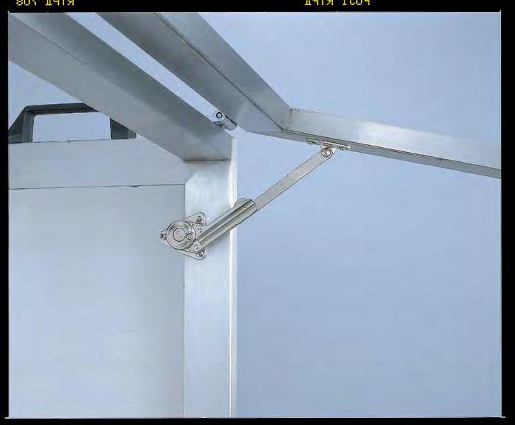
For UPWARD-OPENING FLAP DOOR with piano, concealed butt or drop hinges.
Opening angle 80º, 90º or 100º.
NSDX-35 is designed to hold door in fully opened position. Speed adjustment screw located on front for easy adjustment.
Handed: Specific left and right hand mounting.
Torque Calculation:
- Torque = Door Height x 1/2 x Door Weight
- Per Piece: 19 ~ 60 lbs·inch (20 ~ 70 kg·cm)
- Per Pair: 38 ~ 120 lbs·inch (40 ~ 140 kg·cm)
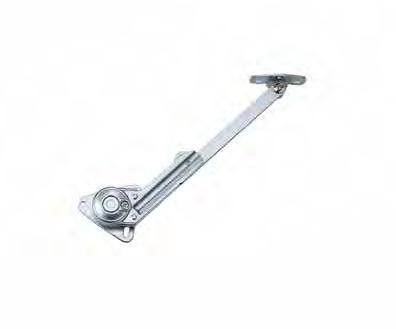
(8.5 mm)
(34 mm) 5/8(16 mm) 29/32(23 mm)
1-17/64 1-31/32 (32 mm) 3-27/64 (87 mm) (50 mm)
This drawing shows NSDX-35RK (right-hand side mounting). NSDX-35LK (left-hand) is symmetrical.
Note: "S" dimension is the overlay coverage for concealed hinge(s).
(32 mm) 55/64 (22 mm)
Arm Mounting Plate
Opening
80° Concealed Hinge 4-11/64" (106 mm)4-9/64" (105 mm)-S4-49/64" (121 mm)-S
Hinge 3-15/16" (100 mm)
3-57/64" (99 mm)4-17/32" (115 mm)
Concealed Hinge 3-35/64" (98 mm)3-13/16" (97 mm)-S4-29/64" (113 mm)-S -
Hinge 3-39/64" (91.5 mm)
Concealed Hinge 3-41/64" (92.5 mm)3-39/64" (91.5 mm)-S4-15/64" (107.5 mm)-S
Hinge 3-11/32" (85 mm)
3-9/16" (90.5 mm)4-3/16" (106.5 mm)
3-5/16" (84 mm)3-15/16" (100 mm)
EASY LIFT-UP STAY
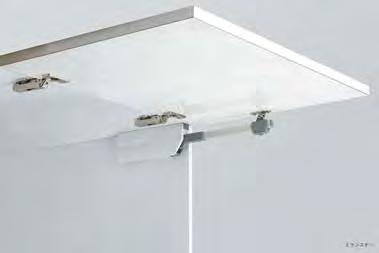
■ Easy Installation
Only 2 Screws needed to secure the body
■ Adjustment
SLS-ELAN-HRRight
SLS-ELAN-HLLeft
SLS-ELAN
For UPWARD-OPENING FLAP DOOR with concealed, piano, butt, or drop hinges.
Designed to provide effortless opening and hold door in closed and opened position.
Damper equipped for soft & silent closing.
Optional bracket for aluminum frame door available.
Single or pair use allows wide range of door size/weights.
Handed: Specific left and right hand mounting.
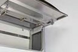
Door Weight Range Table (lbs.)
*Single or pair use depending on door size and weight.
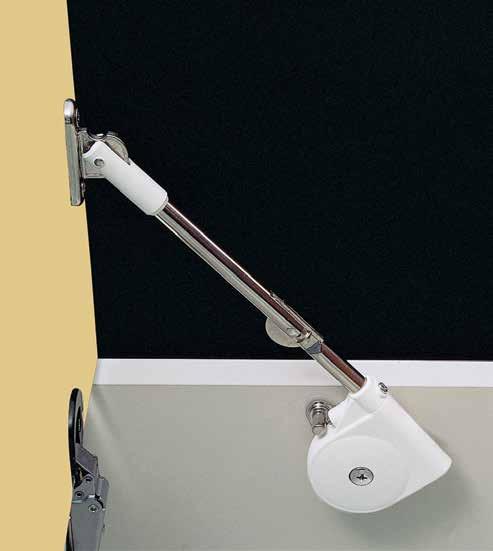
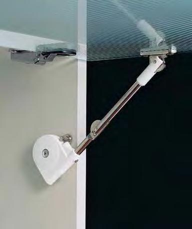

For UPWARD-OPENING FLAP DOOR with concealed, piano, butt or drop hinges. SDS-C301N is designed to hold door in closed and opened position. Non-handed: Can be installed on left or right side.
Torque Calculation:
- Torque = Door Height x 1/2 x Door Weight


Mounting Plate SDS-A
Concealed Hinge
Single Knuckle Hinge
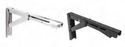
FOR EB FOLDING BRACKET
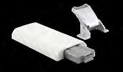
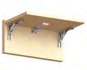
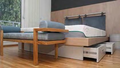
Automatically locks when flap is in opened position. Press lever to release the locking mechanism. Bracket can be used without the need for hinges Available in 2 finishes and 3 different sizes. Only EB-303/EP is NSF.
FOLDING BRACKET WITH SOFT-CLOSE
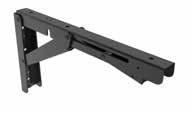
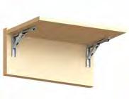
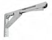
Folding Bracket
Automatically locks when flap is in open position. Press lever to release the lock. Additional hinges not required.
Damper unit with a soft-closing feature which makes bracket smoother and safer.
Refer to DAMPER WEIGHT CHART below for appropriate table weight and depth when softly folding down the table. For panel thickness 9/16" ~ 1-3/8" (15 ~ 35 mm). Durability tested 50,000 cycles (private).
EB-303/EP-D

EB-317/EP-D
To find your Min./Max. table weight per single damper, please reference the formula shown next to the charts above and 18” depth examples below.
EB-303/EP-D
Maximum weight 7.2 lbs = 130/18 in.
Minimum weight 2.8 lbs = 52/18 in.
EB-317/EP-D
Maximum weight 19.1 lbs = 345/18 in.
Minimum weight 12.5 lbs = 225/18 in.
FULL EXTENSION SOFT CLOSE SLIDE
Full extension.
Front disconnect.
Positive stop.
Hold-in detent 700 g-f (1.5 lb) max.
Handed: specific left and right hand mounting.
Sold in pairs.
Inner member clearance provided for screws 8 mm × 2 mm HT.
Outer member clearance provided for screws 8 mm × 2 mm HT.
Mount with M4 or #8 Binding, Pan, or Truss head screws.
* Only on ESR-SC4513-18
(700 mm)
(700 mm)
(544
Rivet #1
The inner rail can be disconnected by pressing the disconnect lever.
/ Nylon 66
Stainless Steel
Retainer Polypropylene
Ball Case 304 Stainless Steel
Hook Block Nylon 66
Rivet #2
304 Stainless Steel
Disconnector Nylon 66
Stopper (Guide) Nylon 6
Balls 304 Stainless Steel
Grease H1 Grade
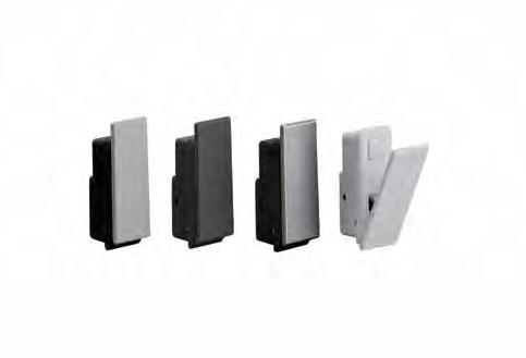
NF-45D-GRNF-45D-BLNF-45D-SSLNF-45D-WT
A modern, clean hook solution with Motion Design Technology.
Hook is spring loaded to retract and soft close. Ideal for vibration or shock applications.
Panel Thickness:
- Wood: Min. 1-1/16" ~ 1-1/4" (27 ~ 31 mm)
- Sheet metal: 0.8 ~ 4.0 mm
Hook bracket (NF-45DB) for sheet metal sold separately.
Wood panel (27~31mm)
Wood panel (32mm or thicker) Sheet metal
Pin 304 Stainless Steel Plain ➄ Spring ➅ Bumper Rubber Black/White Cut Out Dimensions
(pcs) NF-45D-GR Grey
NF-45D-BL Black
NF-45D-SSL Silver
NF-45D-WT White No. Part Name Material Finish ➀ Body Aluminum Alloy Grey/Black/Silver White ➁ Arm ➂ Cover Polyacetal


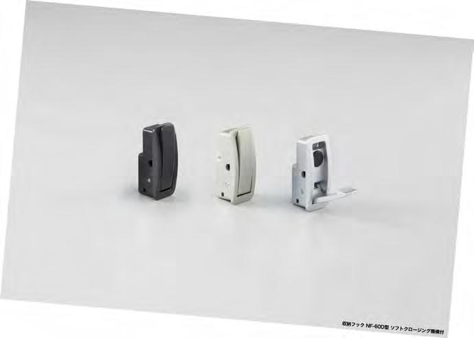
NF-60D SOFT CLOSE RECESSED HOOK

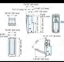
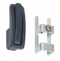
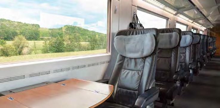
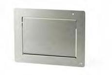
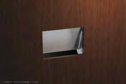
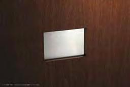
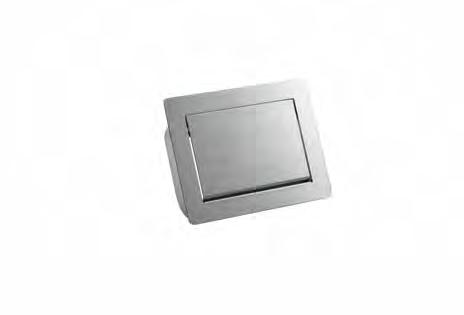
Installed from the inside of the waste box for clean appearance. With damper to keep the lid from slamming shut. Integrated with anti-pinching plates. Corrosion resistant. Guide sold separately (AZ-SLP)
Able to install the lid up to 45º. Inclined mount. Easy to adjust angle by changing the weight position. Integrated anti-pinching plates. Corrosion resistant. Guide sold separately.
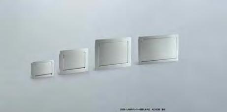
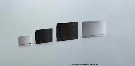


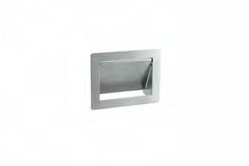
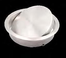
AZ-GD180-HL
AZ-GD230-BL
AZ-GD310-HL
AZ-GD310-BL
(182 mm)
(234 mm)
(310 mm)
(128 mm)
(160 mm)
(220 mm)
AZ-GD400-HL 15-3/4" (400 mm) 8-21/32" (220 mm)
LID
(218
(308 mm)
(384 mm)
(450 mm)
(234
(49
(294 mm)
(64
(244.7
(140
2236
2236
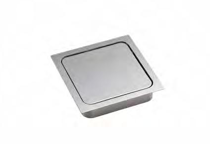
MULTI-PURPOSE LID W/DAMPER
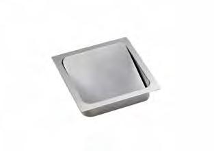
Features damper to keep lid from slamming shut. Made of stainless steel for corrosion resistance. Wide opening. Balance weight restores lid to horizontal position.
MULTI-PURPOSE LID (SOFT CLOSE)
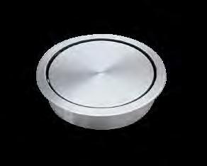
1-7/16" (36 mm) 1/16" (1 mm)
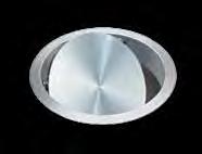
Soft and slow closing movement with a built-in damper mechanism.
Wide opening, self-leveling lid.
Stainless steel for corrosion resistance
Operating temperature: 32ºF ~ 104ºF (0ºC ~ 40ºC). Horizontal use only.
AD-GD011-HLAD-DH011-HL5-3/8" (136 mm)4-3/16" (106 mm)4-3/16" (107 mm)3-7/16" (87 mm)2-7/16" (62 mm)460 1 10
AD-GD015-HLAD-DH017-HL6-11/16" (170 mm)5-3/4" (146 mm)5-13/16" (147 mm)2-15/16" (75 mm)3-9/16" (90 mm)1000 AD-GD020-HL - 8-11/16" (220 mm)7-3/4" (196 mm)7-13/16" (198 mm)3-1/8" (80 mm)5-1/16" (128 mm)1060 6 AD-GD028-HL - 11-13/16" (300 mm)10-7/8" (276 mm)10-15/16" (278 mm)3" (77 mm)7-5/16" (186 mm)1840 4
Lifts and opens easily Assist Motion
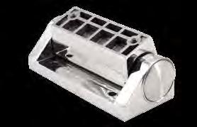
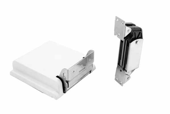
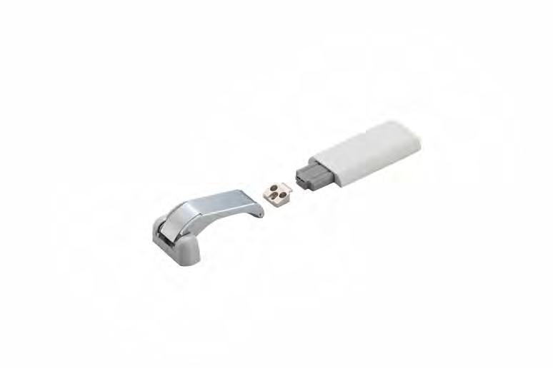
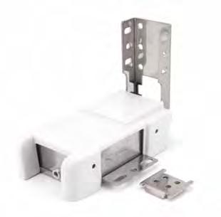
A gentle and controlled way to assist in opening and/or closing heavy doors, lids or covers MAKES LIFTING EFFORTLESS
Torque adjustment screw
Power assist hinge to reduce the effort to open the lid/door.
Internal under mounted.
Soft closing.
Torque adjustable (±11%).
Two optional opening angles at 55º or 80º.
POWER ASSIST HINGE (OUTSIDE MOUNT)
Angle of peak torque is adjustable with hex key 5 mm (13/64").
This feature allows for position adjustment to change the center of gravity.
Mitigates effort needed to lift heavy lids and doors. Balance adjustment allows for use in a wider range of lids than conventional lift-assist hinges. Soft closing.
External surface mounted.
Torque adjustable (±10%).
Features durable plastic cover for clean appearance.
Applications: Medical equipment, analytical instruments, semiconductor equipment.
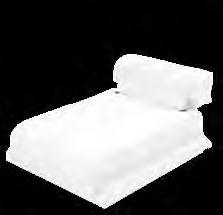
Power assist hinge to reduce the effort to open the lid/door. External surface
(±5%).
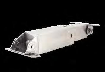
Power assist hinge to reduce the effort to open the lid/door. External surface mounted. Soft closing. Torque adjustable (±5%).
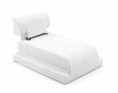
Power assist hinge to reduce the effort to open the lid/door.
External surface mounted.
Soft closing. Torque adjustable (±10%).
No.Part Name Material Finish
➀ Base A 430 Stainless SteelPlain ➁ Base B ➂ Case ➃ Plastic Cover A PBT plasticLight Grey
Cover B
Slider Polyacetal
HINGE
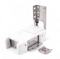
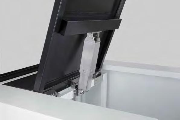
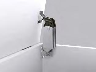
Power assist hinge to reduce the effort to open the lid/door. Internal under mounted. Soft closing Torque adjustable (±10%). Two optional opening angles at 55º or 80º.
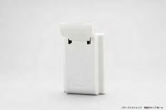
Power assist hinge to reduce the effort to open the lid/door. External surface mounted to save space inside the application. Soft closing function to prevent slamming of the
Torque adjustable (±10%).
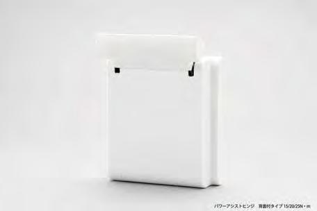
Power
Torque
(35 mm)
(297 mm) 9-5/32 (232.5 mm) 2-35/64 (64.5 mm) 2-23/64 (60 mm) 2-23/64 (60 mm) 1-31/32 (50 mm) 1-31/32(26 mm) 4-23/32 (120 mm) 3-15/16 (100 mm) 1-31/32 (50 mm)
(25 mm)
4-23/32 (120 mm) 63/64 3-15/16 (100 mm) (25 mm) 3/64 (1 mm) 1-3/8 (35 mm) 29/32 (23 mm)
Bracket (included)
operation with power assist
HEAVY DUTY SPRING LOADED LID STAY
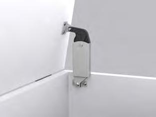
Side wall mounted.
Spring mechanism assists in lifting door and holds in open position (10° ~ 80°). Can be installed individually or in pairs Non-Handed: Can be installed on left or right side. Does not work with concealed hinges
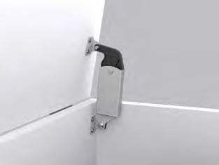
HEAVY DUTY SPRING LOADED LID STAY
Back panel mounted.
Spring mechanism assists in lifting door and holds in open position (10º ~ 80º). Can be used individually or in multiples. Does not work with concealed hinges
S-AT01S, S-AT02S
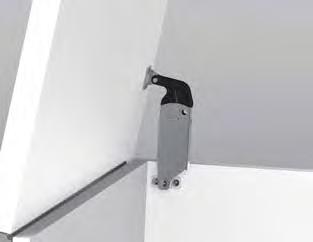
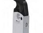


Side wall mounted.
Spring mechanism assists in lifting door and holds in open position (10º ~ 80º).
The balance adjustment allows for use in wider range of lids.
Can be installed individually or in pairs
Non-Handed: Can be installed on left or right side.
Does not work with concealed hinges
Optional add on damper S-ATD
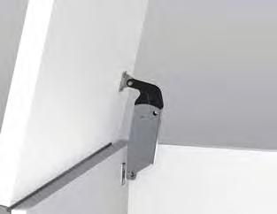
SPRING LOADED LID STAY

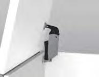


Back panel mounted.
Spring mechanism assists in lifting door and holds in open position (10º ~ 80º).
The balance adjustment allows for use in wider range of lids.
Can be used individually or in multiples.
Does not work with concealed hinges
Optional add on damper S-ATD

BALANCE ADJUSTABLE SPRING LOADED LID STAY


DAMPER FOR S-ATJ & S-ATJD
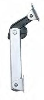
Back panel mounted.
Spring mechanism assists in lifting door and holds in open position (10º ~ 80º).
The balance adjustment allows for use in wider range of lids.
Can be used individually or in multiples. Does not work with concealed hinges
Damper option not available
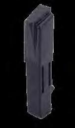
Soft-close damper designed for use with the S-ATJ & S-ATJD. Easy to install.
SPRING LOADED LID STAY
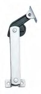
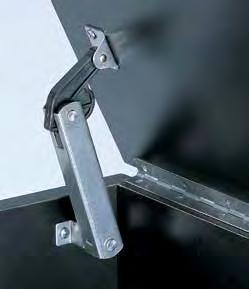
STAINLESS STEEL LIFT ASSIST HINGE
Moment Formula and Graph
Hinge
Spring assists in opening heavy doors Built-in damper keeps lid from slamming shut. Passed private 30,000 open/close cycle tests. Maximum torque: 182 lbs·in (210 kgf·cm) per piece
*In case of HG-JH210 used in pair. (L: 60cm, W1: 13kg, W2:15kg)
(167 mm)
(144 mm)
(100 mm)
LADH LIFT-ASSIST DAMPER (HEAVY DUTY)
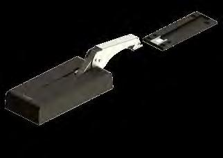
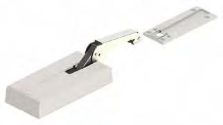
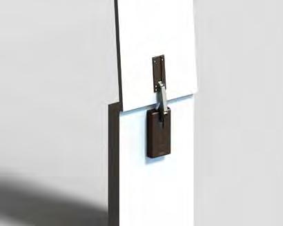
Add a smooth soft-close to counter tops in restaurants, bars and reception desks to prevent slamming.
Lift-Assist feature helps users lift counter top
Holds door open at 95 degrees.
Easy installation - surface mounted and can be retrofitted
Stainless steel piano hinge included (see next page for details)
White
Dark Brown

Ideal for bar and countertop applications
Angle stopper designed to hold open at 95°.
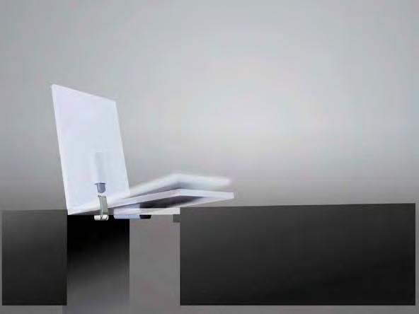
Damper equipped for soft closing.
Simple surface mount installation.
Brackets, spacers and mounting plate accessories available (sold separately)
•
Type
• Assist
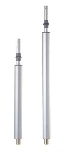
FLL30 HEIGHT ADJUSTABLE LOCKING POLE with Lift-Assist
FLL30-750A-SL
Min:
Max: 170N (at 750mm)
• Manually Operated Round Bar Telescopic Rods.
FLL30-1000A-SL
Min: 100N (at 1350mm)
Max: 170N (at 1000mm)
• Can be locked in any position, whether extended or contracted.
Application
• Such as medical equipment
• Features an assist function, utilising a coil spring to facilitate light lifting.
Remarks
Manually Operated Round Bar Telescopic Rods. Can be locked in any position, whether extended or contracted. Features an assist function, utilising a coil spring to facilitate light lifting The assist power is approximately 22 lbs (10kgf).
• The assist power is approximately 10kgf.
• Please do not ascend or descend without a load (nothing attached).
• There is variation in the assist force due to the structure.
Type
Compatible Parts
• Assist power (in no-load condition)
• BASE HS-550 , PIPE CLAMP (Under Development)
FLL30-750A-SL
Min: 95N (at 1000mm)
Max: 170N (at 750mm)
FLL30-1000A-SL
Min: 100N (at 1350mm)
Max: 170N (at 1000mm)
Application
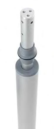
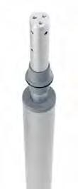
Mounting Section (Top) Mounting Section (Bottom)
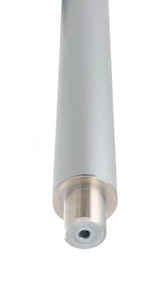
• Such as medical equipment
Remarks
• Please do not ascend or descend without a load (nothing attached).
• There is variation in the assist force due to the structure.
Compatible Parts
• BASE HS-550 , PIPE CLAMP (Under Development)
With assist function for light lifting
Application Example
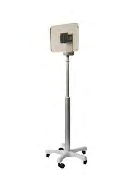
How to Operate
Mounting Section (Top) Mounting Section (Bottom)
Sugatsune’s wide range of specialty magnetic catches are perfect for maintaining a minimalistic look with maximum strength. The magnetic efficiency of our hardware is suitable for food equipment, medical equipment, manufacturing equipment, clean rooms, and storage carts. Visit sugatsune.com to explore our full selection of specialty magnetic catches.
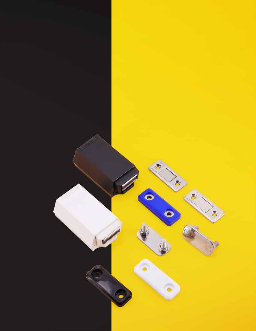
Specialty Magnetic Catches
Click to Stop Detent Motion
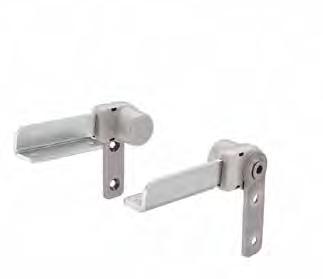
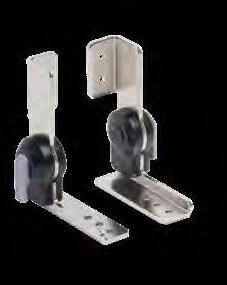
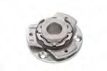
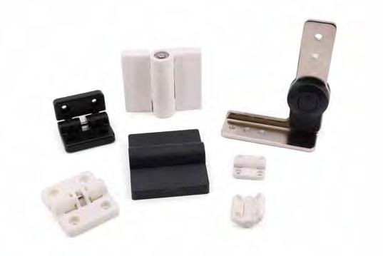
Temporarily holds doors, lids, or covers at a set angle with a distinct “click” during opening and closing.
ONE HINGE MANY ANGLES
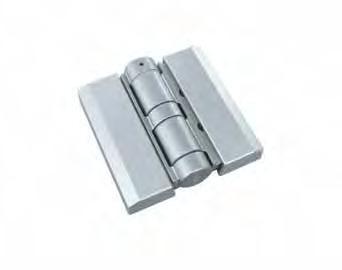
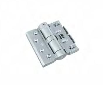
Ideal for doors which need to be compressed. Horizontally adjustable for better compression. Holds doors at 60º and 120°
Max. Open: 152º
Plastic washer provides smooth movement.
Recommended door speci cation:
Width: 24 ~ 36" (600 ~ 900 mm)
Height: 36~ 48" (900 ~ 1200 mm)
Max. Weight: 90 lbs (40 kg) for 2 hinges
Retaining Force: 88.5 lbs·in (102 kgf·cm).
(21.5 mm)
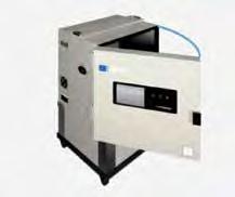
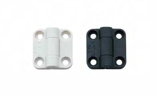
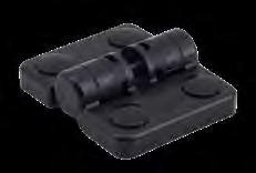
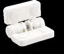
Plastic hinge holds doors at 3 different positions (-10º, 120º, 170º).
Door weight: Max 2.2lbs (1.0kg)/pair
Ideal for small equipment with light weight doors such as measuring devices, medical equipment, etc. Additional stopper recomended at 0º and 170º.
Covers)
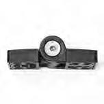
Holds at 4 angles: -3º, -90º, 90º and 177º (factor y setting). The holding angle of 90º can be switched to 45º or 135º. Can be used both ver tically and horizontally. Ideal for environmental test equipment or laborator y equipment. Adjustments of angles must be made when hinge is in opened position. Use 5mm hex key for tension adjustment screw.
Holds in position Available Detent Angles
Can be adjusted by a hex key Application Example
Weight: Max. 17.64 lbs (8 kg)
Width: Max. 19-11/16" (500 mm)
Height: Max. 39-3/8" (1,000 mm)
Torque: Max. 15.05 lbs in
Height: Max. 9-27/32" (250 mm)
Torque: Max. 21.24 lbs in
Height: Max. 11-13/16" (300 mm)
You can change the temporary holding angle!
All 3 angles available in one hinge

When maintaining temperatures is crucial, 45° opening keeps cold or hot temperatures from escaping.
The 90° opening setting keeps doors from interfering with adjacent equipment.
At 135° setting the opening allows full clearance and complete access.
No.Part Name Material Finish
➀ Body Polyacetal Ivory/Black
➁ Hinge Pin303 Stainless SteelPlain
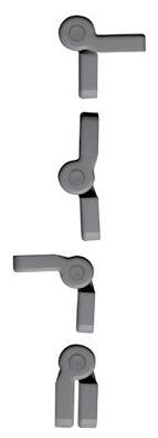
➂ Cap PolypropyleneIvory/Black Holds at 4 positions, 90º each.
CENTER HINGE FOR FOLDING DOORS
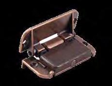
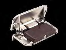
Plastic hinge holds doors at 4 different positions (90°each) without secondary support. Ivory or Black available.
Max door sizes:
180° opening with detent function (up to 90º).
Hinge snaps in at open and closed positions.
Ideal for folding doors in fur niture, folding screens, light duty partitions, and similar applications. Removable hinge pin allows for easy installation. Designed for use with solid wood and MDF. Can also install to aluminum frame with AS-CH-75 par ts set (sold separately).
MICRO DETENT HINGES
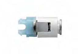
Ultra compact detent hinge suitable for clamshell type cell phones, PDA and other foldable devices.
Small diameter of Ø5 for space-saving and downsizing of casing. Designed for 160º opening, and detent catch in open and closed position.
Easy snap-in for quick assembly.
Passed 100,000 open/close private cycle test.
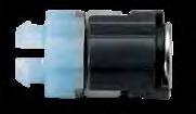
Ultra compact detent hinge suitable for clamshell type cell phones, PDA and other foldable devices.
Designed for 160º opening, and detent catch in open and closed position.
Easy snap-in for quick assembly.
Passed 100,000 open/close private cycle test.
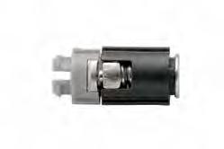
Ultra compact detent hinge suitable for clamshell type cell phones, PDA and other foldable devices.
With the torque of a single hinge equal to that of two conventional hinges, you can design various casings as there is no need for hinge space on the other side.
Designed for 160º opening, and detent catch in open and closed position.
Easy snap-in for quick assembly.
Passed 100,000 open/close private cycle test.
HG-MA95A MULTI ANGLE LOCKING HINGE
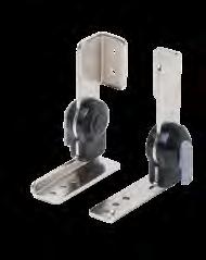
Left-handed
Left-handed Right-handed
Right-handed
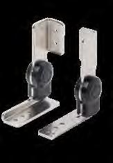
Holds in position at angles in 10° increments
Holds in position at angles in 10° increments
(R20 mm)
(14.5 mm)
(94.5 mm)
(40 mm)
(35 mm)
(46 mm)
(73 mm)
(52 mm)
(31.5mm)
(14.2 mm)
(4 mm) 5/32" (4 mm)
(17 mm)
Left-handed shown. Right-handed is symmetrical.
Left-handed With locking lever
Lock allows the hinge to be held in position from 0º to 180º in 10º increments. (Available without lock) Easily adjusts the flap angle by toggling the lever. The flap is temporarily unlocked while the lever is pushed. The flap stays unlocked when the lever is lifted. Both hinge types can be used together.
Ideal for medical equipment, analytical instruments, semiconductor equipment.
Two Ways To Unlock
The flap is temporarily unlocked while the lever is pushed.
The flap stays unlocked when the lever is lifted.
Rotation Angle 188°
Right-handed HG-MA95AF-L Left-handed Without non-locking lever Free Swinging HG-MA95AF-R Right-handed No.Part NameMaterialFinish
Bracket SteelNickel
MULTI ANGLE LOCKING HINGE
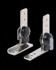
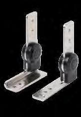
Locus Chart 18×10°(=180°)
Holds in position at angles in 10° increments
Holds in position at angles in 10° increments
(R20 mm)
(20 mm)
(73 mm)
(52 mm)
(29 mm)
Lock allows the hinge to be held in position from 0º to 180º in 10º increments. (Available without lock) Easily adjusts the flap angle by toggling the lever. The flap is temporarily unlocked while the lever is pushed. The flap stays unlocked when the lever is lifted. Both hinge types can be used together.
Ideal for medical equipment, analytical instruments, semiconductor equipment.
Two Ways To Unlock
Partially unlocked
The flap is temporarily unlocked while the lever is pushed.
Fully unlocked
The flap stays unlocked when the lever is lifted.
Left-handed shown. Right-handed is symmetrical.
(13 mm)
(14.2 mm)
(R20 mm)
(2×ø6.2 mm)
(80 mm)
(3×ø6.2 mm)
HG-MA95BF-L
HINGE WITH FRICTION
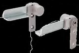
Ratchet hinge holds at 18 angles in 5º increments from the closed position to the 90º max opened position.
Lift up to the fully open position 108º to release the ratchet mechanism.
The friction (resistance) function works when released for safe operation.
Ideal for adjustable work surfaces such as keyboard trays or desks.
Max. torque: 354 lbs • in/pair (408 kgf • cm/pair).
Each hinge requires 4 No. 12 (M5.5) flathead countersunk screws for installation (Screws not included).
Sold in pairs
Application Example Lock Release
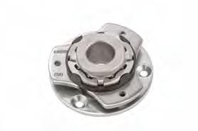
Application Examples
Horizontal: Cycle Test 20,000 times
Rotation angle: 360º Detent Hinge.
2 types: Holds at each 30º or Holds at each 90º Centre hole for cable management. The friction function works when non-click section.
Operating temperture: 32ºF ~ 104ºF (0ºC ~ 40ºC).
Tablet stand or Operation panel of machine tools, LCD, etc. M4 countersunk screws (3 pcs), M4 Screws (3 pcs).
Mounting direction and allowable vertical load/allowable moment Vertical Load Capacity
(The center of gravity of the load and the axis of rotation are the same).
Horizontal mounting: on a table, etc.
of Rotation
Mounting Direction Examples
Attach the plate B side first, then attach the plate A side. Vertical mounting: for adjusting the angle of the monitor, etc.
A
*Reference load capacity: 1.5kg (at the position of 20mm offset load)
(The center of gravity of the load and the axis of rotation do not match)
Allowable Movement Load's Center of Gravity Load's Center of Gravity Load's Center of Gravity
of Rotation Axis of Rotation
Mounting hole machining drawing
※If the mounting thickness is 6.5mm or less, within ø42 Make sure that the washer of the threaded part does not protrude.
No.Part Name Material Finish
1Shaft 303 Stainless SteelPlain
2Spring Base430 Stainless Steel Polished
3Spring PlateStainless Steel
4Ball HolderPolyacetal (POM)
5 Plate A 430 Stainless SteelGloss Polished
6Resin WasherPolyacetal (POM)
7Plate B430 Stainless SteelGloss Polished
Stainless Steel Handles
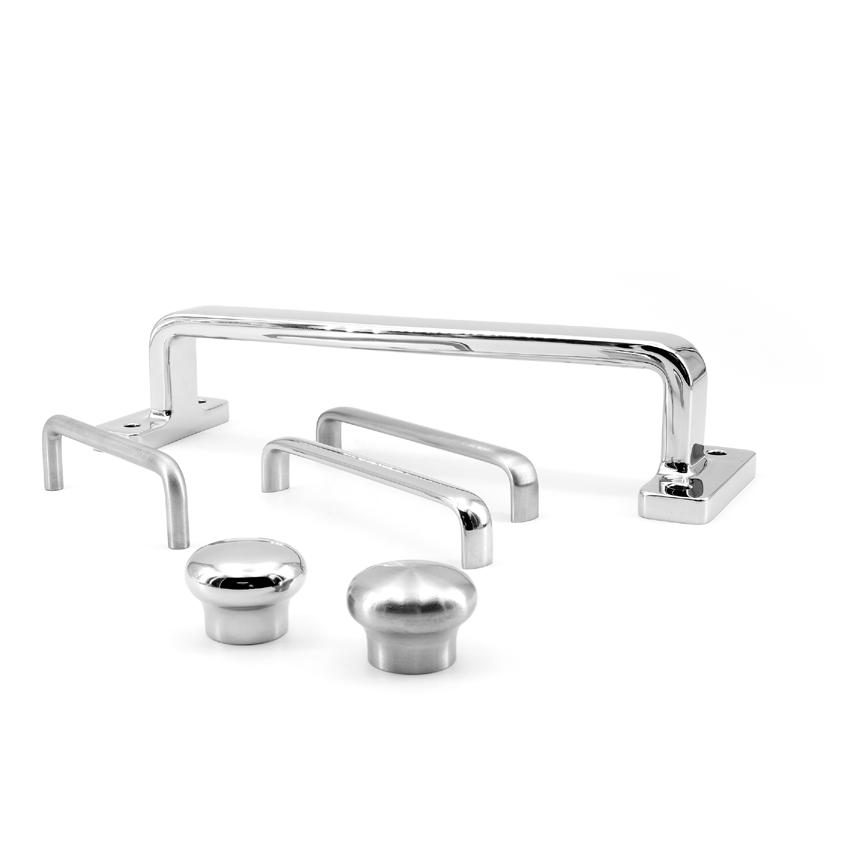
Innovative openings Unique Motion
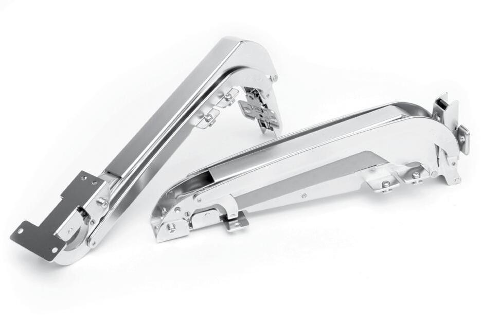
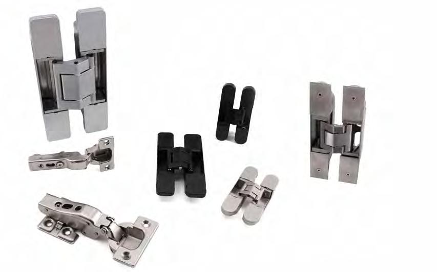
Expands the range of opening and closing motion paths.
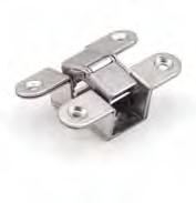
LINKING MECHANISM FOR MOVEMENT
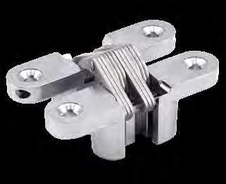
Distance between door edge and hinge must be less than the figures shown in column "X" of the dimension table below.
To determine the number of hinges required for each door:
• Using the chart to the right, locate the correct door width (upper scale) and door weight (lower scale). Draw a line connecting these 2 points to the chart below (point "a"). Then draw a vertical line through the lower chart to find the number and type of hinges required.
• Check door thickness requirements.
In case of door width, 700mm and door weight, 15kg
Door size: Max. W17-23/32" x H27-9/16" x t53/64" (W450
x H700 mm x t21 mm)
No.Part Name Material Finish
➀ Body Zinc Alloy Stain Chrome
➁ Link Arm
304 Stainless Steel
➂ Pin A R-43~70
➃ Pin B304 Stainless Steel
304 Stainless Steel Plain R-100, Steel
➄ Pin C R-43~70
304 Stainless Steel R-100, Steel
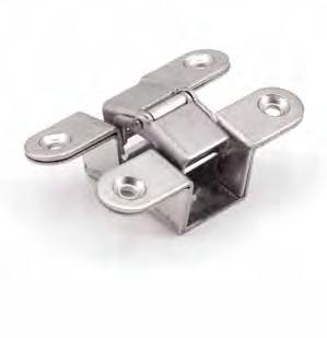
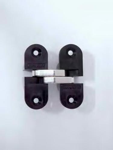
Door

Cut Out Dimension
Please drill prepared holes for the tapping screws if the optional jig (HES3D-W190-TMP) is not used.
The example drawing shows the case that there is a step of 10 mm between the door and the frame.

Has a long arm for a wider throw, allowing 3/8" (10 mm) clearance for flush installation or 1/2" (13 mm) clearance for installation with a molding. Opens to 180 degrees. Features 3-way adjustability (vertical, horizontal and depth).
UL Rated, up to 3 Hours (DC, DN, and BL models only)
Flanges come apart for the door to be provisionally hung for making adjustments. This provides a quick and easy installation when ready for fixing screws.
Successfully passed 300,000 open/ close private cycle tests
Replacement screw covers available for all finishes.
Only the HES3D-W190PN model includes metal cover plates*, all other models include plastic cover plates.
Flush Installation
Installation with Molding
If something is attached to a frame, for example decorative sheets, please include the thickness into the X.
3-WAY ADJUSTABLE CONCEALED HINGE

HES3D-E190PN-ULHES3D-E190DC-ULHES3D-E190DN-ULHES3D-E190BL-ULHES3D-E190WT-UL
3-WAY adjustment function allows vertical, horizontal, and depth adjustment after hinge installed.
Easy installation with LIFT-OFF FEATURE: can be split into two parts (one for the frame and one for the flap), can temporarily be hung and hold position without being affixed with screws.
Successfully passed 300,000 open/close private cycle tests.
UL Rated, up to 3 Hours
Supplied with steel flat head screw.
Covers hide all screw heads for clean appearance.
Door weight max: 220 lbs (100 kg)/2 pcs, 275 lbs (125 kg)/3 pcs.
Door thickness min: 1-1/2" (38 mm).
Max. door size: H 94-1/2" (2400 mm) × W 35-7/16" (900 mm).
Bracket for sheet metal doors and frames available (sold separately).
Metal cover plates (HES3D-E190PN-CM) sold separately for Polished Nickel (PN) finish.
Metal cover plates included with Bright Brass (BB) finish.
HES3D-E190PN-ULPolished Nickel
HES3D-E190DC-ULDull Chrome
HES3D-E190DN-ULDull Nickel
HES3D-E190BL-ULMatte Black
HES3D-E190WT-UL White
HES3D-E190BB-ULBright Brass
Polished Nickel (PN)
Dull Chrome (DC)
Dull Nickel (DN)
Matte Black (BL), White (WT)
Bright Brass (BB)
Polished Nickel (PN)
Dull Chrome (DC)
Dull Nickel (DN)
Matte Black (BL), White (WT)
Bright Brass (BB)
Polished Nickel (PN)
Dull Chrome (DC)
Dull Nickel (DN)
Matte Black (BL), White (WT)
Bright Brass (BB)
Polished Nickel (PN)
Dull Chrome (DC)
Dull Nickel (DN)
Matte Black (BL), White (WT)
Bright Brass (BB)
3-WAY ADJUSTABLE CONCEALED HINGE
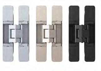
Easy installation with symmetrical leaves and lift-off feature. 3-WAY adjustment function allows vertical, horizontal, and depth adjustment after hinge installed.
Door weight max: 121 lbs (55 kg)/2 pcs, 154 lbs (70 kg)/3 pcs
Door thickness min: 1-3/8" (35 mm)
Max. door size:
*Chamfer the marked part with C1, R1 or a larger value.
To determine the door and frame dimension, (G) must be taken into account. G = Min. 6 mm +
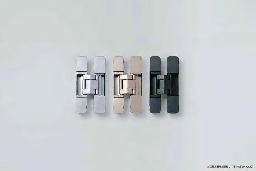
3-WAY adjustment function allows vertical, horizontal, and depth adjustment after hinge installed.
Easy installation and adjustment.
Successfully passed 300,000 open/close private cycle tests.
Supplied with steel flat head screw.
Covers hide all screw heads for clean appearance.
Door weight max: 66 lbs (30 kg)/2 pcs, 88 lbs (40 kg)/3 pcs
Door thickness min: 1-1/8" (29 mm)
Max. door size: H 94-1/2" (2400 mm) × W 35-7/16" (900 mm)
Bracket for sheet metal available
HES3D-120DCDull Chrome 380 2 24
HES3D-120DNDull Nickel
HES3D-120BLBlack
HES3D-120DN
HES3D-120BL

3-WAY adjustment function allows vertical, horizontal, and depth adjustment.
Covers hide all screw heads for clean appearance. Hinge leaves separate for easy installation and adjustment. Door weight max: 26 lbs (12 kg)/2 pcs, 35 lbs (16 kg)/3 pcs
3-WAY ADJUSTABLE CONCEALED HINGE
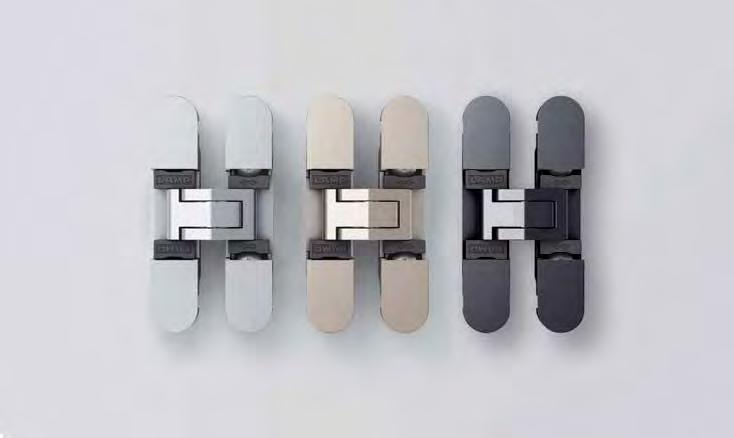
3-WAY adjustment function allows vertical, horizontal and depth adjustment after installation. Hinge leaves separate for easy installation. Covers hide screw heads for clean appearance. Includes
HES3D-70DN
HES3D-70DC
HES3D-70BL
3-WAY ADJUSTABLE STAINLESS STEEL CONCEALED HINGE
304 stainless steel construction for excellent resistance to corosion. 3-way adjustable allowing for vertical, horizonta and depth adjustments after installation.
Hinge leaves are designed to seperate and features a temporary hold function making it easier to hang doors.
Durability: successfully passed 300,000 open/close cycle test (private). Includes covers for a clean finish. Optional square shaped covers are available (HGS3D-S160SH-SQPLATE)
3 hinges can support doors up to 35-7/16" x 94-1/2" weighing up to 220 lbs. UL Rated, up to 3 Hours
door and frame must be chamfered in accordance with the machining margin, in order to open and close the

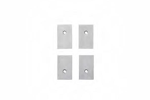
Figure shows top screw cover removed. With square screw cover (optional)
Round Screw Cover
SPECIALTY OVERLAY HINGE W/ SOFT-CLOSE (25MM OVERLAY)
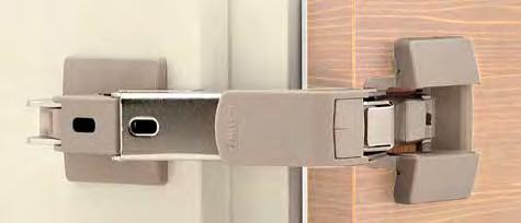
3-way adjustability with built-in damper.
Load capacity: 55 Ibs (25 kg)/2 pcs, 88 lbs (40 kg)/3 pcs.
Maximum door width: 31-1/2" (800 mm)/2 pcs, 35-7/16" (900 mm)/3 pcs.
Wide-opening hinge allowing 160° opening. Successfully passed 50,000 open/close private cycle test.
Recommended door thickness: 11/16 ~ 1-7/16" (18 ~ 36 mm).
Includes mounting plates and screw covers. Built in damper allows doors to soft-close.
Door Depth: 19/32” (15 mm)
1-47/64” (64 mm) (44 mm) (32 mm)
2-53/64” (72 mm) (30 mm) 1-3/16”1-17/64”
4 prepared holes
Dimensions
Material Finish
Steel, Zinc Alloy (ZDC), Glass Filled Polyamide (PA) Nickel (NI), Black Nickel (BN)
Door edge to bore edge distance (C) and Overlay distance (E)
Overlay adjustment (Max.-4mm) by turning the overlay adjustment screw.
Opening Clearance (O.C.)
Clearances for door edge O.C. (A) and hinge side O.C. (B) are necessary. O.C. (A) and (B) change depending on door thickness and bore distance (C). Refer to locus chart and tables below when designing cabinets.
Hinge side opening clearance chart
Door Thickness (D)*
Door edge to bore edge distance (C) 1/8"(3)5/32"(4)13/64"(5)15/64"(6)9/32"(7)15/16"(8) 1-11/32"(34) and under 0.1 and under 1-27/64"(36) 1/64"(0.2)1/64"(0.2)1/64"(0.2)1/64"(0.2)1/64"(0.2)1/64"(0.2) 1-1/2"(38)* 1/64"(0.5)1/64"(0.5)1/64"(0.5)1/64"(0.5)1/32"(0.6)1/32"(0.6) 1-37/64"(40)* 3/64"(1.0)
*Please refer to the locus chart if door thickness is over 36 mm. (O.C. (B) can be made smaller by R chamfering (round chamfer) or C chamfering (chamfer plane) on the door)
Door edge to bore edge distance (C)1/8"(3)5/32"(4)13/64"(5)15/64"(6)9/32"(7)15/16"(8) Overlay distance (E) 25/32"(20)53/64"(21)55/64"(22)29/32"(23)15/16"(24)63/64"(25) Door Thickness (D)*
25/32"(20)1/16"(1.6) 3/64"(1.2) 3/64"(1.0) 1/32"(0.8) 1/32"(0.7) 1/32"(0.6) 1/64"(0.5) 1-3/16"(30)5/64"(1.9) 1/16"(1.4) 3/64"(1.2) 3/64"(1.0) 1/32"(0.8) 1/32"(0.7) 1/32"(0.7) 1-27/64"(36)5/64"(1.9) 1/16"(1.5) 3/64"(1.2) 3/64"(1.0) 1/32"(0.8) 1/32"(0.7) 1/32"(0.7) O.C. (A)
Nickel (NI)
Black Nickel (BN)
Table-1
Table-2
Table-3
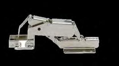
For use with sheet metal applications. Overlay adjustment from 1 ~ 3 mm. Ideal for when 2 doors are close together.
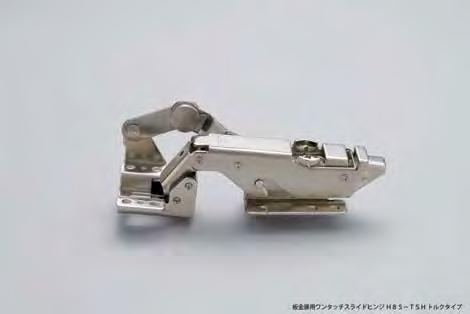
Torque concealed hinge with free stop holds door open at any position up to 95º opening (prevents slamming).
Door opens without interfering with side cabinets, wall, or other adjacent objects.
Ideal for door maintenance in limited spaces: gaming industry, vending machines, kiosks, contiguous swing doors.
Simple clip-on installation and detachment: hinge can be easily fixed onto the mounting plate by pressing down.
The safety pin prevents accidental unlocking.
Durability: 10,000 open/close cycles passed (private test).
Mounting plate (H95TSZ) sold separately.
Easy Installation and Detachment
Holds in position even if the door is inclined.
Example Door Spec
Max. 31-57/64" (810 mm)
- Height: Max. 31-57/64" (810 mm)
- Width: Max. 18-21/32" (474 mm)
- Thickness : Max. 3-5/8" (92 mm)
- Weight: Max. 44 lbs. (20 kg)
* 2 hinges used with 2 mounting plates
Max. 18-21/32" (474 mm)

Door Locus Comparison
Butt Hinge
The hinge is placed outside.
The door hits nearby objects
Alternative Installations
Can be used on doors lined up side by side.
Torque Graph
Concealed Hinge
The hinge is placed inside.
The door does not hit nearby objects
Although the torque will be released to prevent "spring-back" at a nearly closed angle, the door will not be firmly kept closed. If detent function is needed, please use with catches.
Changes in Torque Strength
4.4 lbs·in at 0º opening angle
31 lbs·in at 20º to 25º opening angle
17.7 lbs·in at max 95º opening angle
Free Stop
Torque Mechanism
Safety pin
Cut Out Dimensions
The drawing shows the installation position in the conditions below:
- Bore distance : 13/64" (5 mm)
- Door thickness : 1-3/16" (30 mm)
- Overlay : 17/32" (13.6 mm)
Plate (Sold Separately)
*Load Capacity rated using 2 hinges with 2 moounting plates.
* Please prepare "Bracket for mounting plate" and "Bracket for cup".
Locus Chart
Reference door weight: 44 lbs (20 kg) (In case of door size W 17-23/32" (450 mm) x H 31-1/2" (800 mm), pitch 21-21/32" (550 mm), vertical use)
Hinge Mounting
CONCEALED HINGE (CLIP-ON)
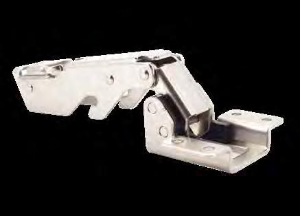
1-55/64
1-17/32 (47.3 mm) (39 mm) 11/16 (17.5 mm) 1 (25.5 mm) 3-21/64 (84.5 mm) 39/64 (15.5 mm)
1-1/16 (27 mm) O.C.=Opening clearance
95º opening concealed hinge
Clip-on feature allows easy door installation/removal. SAFETY LOCK FEATURE. Door opens without interfering side cabinets. Ideal when 2 doors are close together. Hinge body and mounting plate sold separately.
1-11/16 (42.75 mm)
5/32 (3.9 mm) - Hinge side O.C. 17/32 (13.6 mm) - Overlay Distance 13/64 (5 mm) (Door edge to bore edge distance)
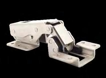
95º opening concealed hinge
2-43/64 (67.7 mm) 2-29/64 (62.4 mm) 1-17/64 (32 mm) 5/8 (16 mm) 5/8 (15.75 mm) (42.75
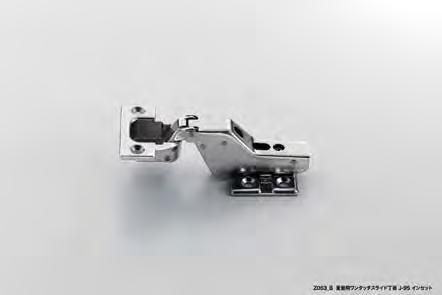
HEAVY DUTY CONCEALED HINGE (INSET) J95-24/0T,J95-C24/0T
• Load capacity: 25 kg (55 Ibs)/2 pcs, 40 kg (88 lbs)/3 pcs.
Load capacity: 55 Ibs (25 kg)/2pcs, 88 lbs (40 kg)/3pcs.
• Maximum door width: 800 mm (31-1/2")/2 pcs, 900 mm (35-7/16")/3 pcs.
• Clip on type for easy installation.
Max. door width: 31-1/2" (800 mm)/2 pcs, 35-7/16" (900 mm)/3 pcs.
• 3-way adjustment with door installed. Requires 6 M5 or equivalent (US#10) screws: 2 pcs for each hinge, and 4 pcs for each mounting plate. Optional hinge cover (J95SC-0) and mounting plate cover (J95ZC) available (sold separately p.288).
• For glass door applications, see page 287.
Clip on type for easy installation. 3-way adjustment with door installed. Requires 6 M5 or equivalent (US#10) screws: 2 pcs for each hinge, and 4 pcs for each mounting plate ver and mounting plate cover available (see pgs. 148-149). Glass face plate (GH-J95FP) also available (see pgs. 148-149).
*Requires J95-P6T Mounting plate sold separately


J95ZC-GR/NI/BC Mounting Plate Cover Sold Separately (See p.288)
J95SC-0GR/NI/BC Safety Cover Sold Separately (See p.288)
edge to bore edge distance (C) 345678 Hinge side O.C. (b)
Mounting plate sold separately █ Hinge
J95-24/0T-NIFree Swing 148
J95-C24/0T-NISelf-Closing 160
J95-24/0T-BNFree Swing 148
*If the door thickness is over 30mm (1-3/16") the door will need to be chamfered.
J95-C24/0T-BNSelf-Closing 160 Part NameMaterial Cup Zinc Alloy Body Steel
J95-P6T Mounting Plate (sold separately p.288).
Nickel (NI)
Black Nickel (BN)
Grey (GR) Nickel (NI) Black Chrome (BC)
Grey (GR) Nickel (NI) Black Chrome (BC)

(INSET) J95-24/0T,J95-C24/0T
• Load capacity: 25 kg (55 Ibs)/2 pcs, 40 kg (88 lbs)/3 pcs.
Load capacity: 55 Ibs (25 kg)/2 pcs, 77 lbs (35 kg)/3 pcs.
• Maximum door width: 800 mm (31-1/2")/2 pcs, 900 mm (35-7/16")/3 pcs.
• Clip on type for easy installation.
Max. door width: 31-1/2" (800 mm)/2 pcs, 35-7/16" (900 mm)/3 pcs.


J95-24/0T-NIFree Swing 148
J95-C24/0T-NISelf-Closing 160
J95-24/0T-BNFree Swing 148
J95-C24/0T-BNSelf-Closing 160
Clip on type for easy installation.
3-way adjustment with door installed.
Requires 6 M5 or equivalent (US#10) screws: 2 pcs for each hinge, and 4 pcs for each mounting plate.
• 3-way adjustment with door installed. Requires 6 M5 or equivalent (US#10) screws: 2 pcs for each hinge, and 4 pcs for each mounting plate. Optional hinge cover (J95SC-0) and mounting plate cover (J95ZC) available (sold separately p.288).
Optional hinge cover and mounting plate cover available (see pgs. 148-149).
Glass face plate required for glass door application (see pgs. 148-149).
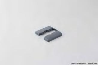
█ Hinge side opening clearance chart
Glass thickness (D) 8 9.5 (3/8") 0 10 0
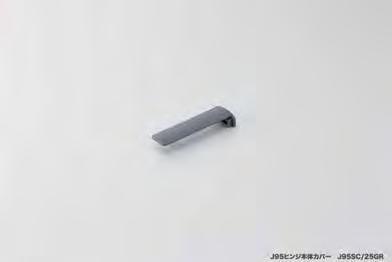
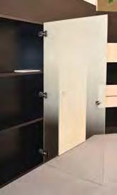
Nickel (NI)
Black Nickel (BN)
HEAVY DUTY CONCEALED HINGE (25mm OVERLAY)
HEAVY DUTY CONCEALED HINGE (25mm OVERLAY)
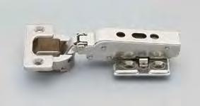
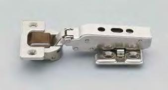
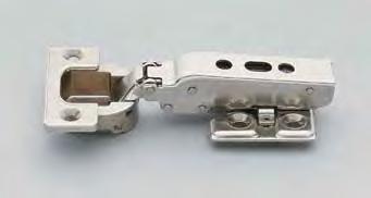
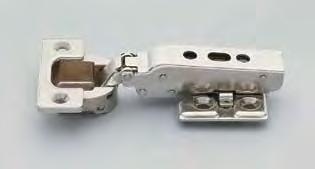
• Load capacity: 25 kg (55Ibs) / 2pcs, 40kg (88lbs) / 3pcs.
• Load capacity: 25 kg (55Ibs) / 2pcs, 40kg (88lbs) / 3pcs.
• Load capacity: 25 kg (55 Ibs)/2 pcs, 40 kg (88 lbs)/3 pcs.
• Maximum door width: 800mm (31-1/2" ) / 2pcs, 900mm (35-7/16" ) / 3pcs.
• Maximum door width: 800mm (31-1/2") / 2pcs, 900mm (35-7/16") / 3pcs.
• Clip on type for easy installation.
Load capacity: 55 Ibs (25 kg)/2pcs, 88 lbs (40 kg)/3pcs.
• Clip on type for easy installation.
• Maximum door width: 800 mm (31-1/2")/2 pcs, 900 mm (35-7/16")/3 pcs.
Max. door width: 31-1/2" (800 mm)/2 pcs, 35-7/16" (900 mm)/3 pcs.
• 3-way adjustment with door installed.
• 3-way adjustment with door installed.
• Clip on type for easy installation.
Clip on type for easy installation.
• Requires 6 M5 or equivalent (US#10) screws: 2 pcs for each hinge, and 4 pcs for each mounting plate.
• 3-way adjustment with door installed.
• Requires 6 M5 or equivalent (US#10) screws: 2 pcs for each hinge, and 4 pcs for each mounting plate.
• Optional hinge cover (J95SC-25GR) and mounting plate
• Load capacity: 25 kg (55Ibs) / 2pcs, 40kg (88lbs) / 3pcs.
• Optional hinge cover (J95SC-25GR) and mounting plate cover (J95ZC-GR) available.
• Requires 6 M5 or equivalent (US#10) screws: 2 pcs for each hinge, and 4 pcs for each mounting plate.
• Maximum door width: 800mm (31-1/2" ) / 2pcs,
Requires 6 M5 or equivalent (US#10) screws: 2 pcs for each hinge, and Glass face plate (GH-J95FP) also available (see pgs. 148-149).
• Clip on type for easy installation.
• Optional hinge cover (J95SC-25) and mounting plate cover (J95ZC) available (sold separately p.288).
• 3-way adjustment with door installed.
• For glass door applications, see page 283.
• Requires 6 M5 or equivalent (US#10) screws: 2 pcs for
• Optional hinge cover (J95SC-25GR) and mounting plate


J95-24/25T-NIFree Swing 131
J95-C24/25T-NISelf-Closing143
J95-C24/25T-NISelf-Closing 143
J95-24/25T-BNFree Swing131
J95-C24/25T-BNSelf-Closing143
J95-24/25T-BNFree Swing 131
J95-C24/25T-BNSelf-Closing 143
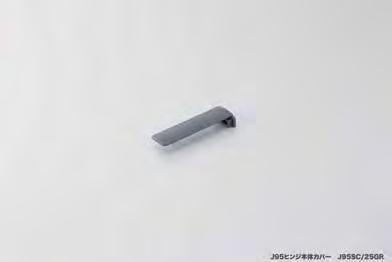
J95ZC-GR/NI/BC
Mounting Plate Cover Sold Separately

Mounting Plate Cover and Safety Cover Sold Separately. See Pages 48-49 for full selection
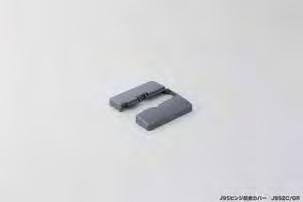
Door edge to bore edge distance (C) and Overlay distance (E) Table 1. Hinge
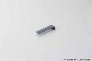
J95SC-25GR/NI/BC Safety Cover Sold Separately (See p.288)
*Mounting Plate sold separately.
*If the door thickness is over 30mm (1-3/16") the door will need to be chamfered.
Plate sold separately.
the door thickness is over
Wood Application
Wood Door Application
Grey (GR)
Black Chrome (BC)
Grey (GR) Nickel (NI) Black Chrome (BC)
HEAVY DUTY CONCEALED HINGE (25mm OVERLAY)


• Load capacity: 25 kg (55 Ibs)/2 pcs, 40 kg (88 lbs)/3 pcs.
• Maximum door width: 800mm (31-1/2" ) / 2pcs, 900mm (35-7/16" ) / 3pcs.
• Clip on type for easy installation.
Load capacity: 55 Ibs (25 kg)/2pcs, 88 lbs (40 kg)/3pcs.
Max. door width: 31-1/2" (800 mm)/2 pcs, 35-7/16" (900 mm)/3 pcs.
• Maximum door width: 800 mm (31-1/2")/2 pcs, 900 mm (35-7/16")/3 pcs.
• 3-way adjustment with door installed.
• Clip on type for easy installation.

Clip on type for easy installation. 3-way adjustment with door installed.
•
• Requires 6 M5 or equivalent (US#10) screws: 2 pcs for each hinge, and 4 pcs for each mounting plate.
• 3-way adjustment with door installed.
• Requires 6 M5 or equivalent (US#10) screws: 2 pcs for each hinge, and 4 pcs for each mounting plate.
• Optional hinge cover (J95SC-25GR) and mounting plate cover (J95ZC-GR) available.
• Optional hinge cover (J95SC-25) and mounting plate cover (J95ZC) available (sold separately p.288).
Requires 6 M5 or equivalent (US#10) screws: 2 pcs for each hinge, and Optional hinge cover and mounting plate cover available (see pgs. 148-149). Glass face plate required for glass door application (see pgs. 148-149).


• Requires 6 M5 or equivalent (US#10) screws: 2 pcs for

Optional hinge cover (J95SC-25GR) and mounting plate


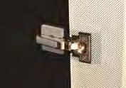
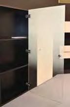
J95-24/25T-NIFree Swing131
J95-24/25T-NIFree Swing 131
J95-C24/25T-NISelf-Closing143
J95-24/25T-BNFree Swing131
J95-C24/25T-NISelf-Closing 143
J95-C24/25T-BNSelf-Closing143
J95-24/25T-BNFree Swing 131
J95-C24/25T-BNSelf-Closing 143
NameMaterial Cup Zinc Alloy Body Steel

HEAVY DUTY CONCEALED HINGE (16mm OVERLAY)
• Load capacity: 25 kg (55Ibs) / 2pcs, 40kg (88lbs) / 3pcs.


J95-24/16T-NIFree Swing 131
J95-C24/16T-NISelf-Closing 143
J95-24/16T-BNFree Swing 131
J95-C24/16T-BNSelf-Closing 143
*Requires J95-P6T Mounting Plate (sold separately p.288).
• Maximum door width: 800mm (31-1/2" ) / 2pcs, 900mm (35-7/16" ) / 3pcs.
• Load capacity: 25 kg (55 Ibs)/2 pcs, 40 kg (88 lbs)/3 pcs.
Load capacity: 55 Ibs (25 kg)/2pcs, 88 lbs (40 kg)/3pcs
• Clip on type for easy installation.
Max. door width: 31-1/2" (800 mm)/2 pcs, 35-7/16" (900 mm)/3 pcs.
• Maximum door width: 800 mm (31-1/2")/2 pcs, 900 mm (35-7/16")/3 pcs.
• 3-way adjustment with door installed.
• Clip on type for easy installation.
• Requires 6 M5 or equivalent (US#10) screws: 2 pcs for each hinge, and 4 pcs for each mounting plate.
• Load capacity: 25 kg (55Ibs) / 2pcs, 40kg (88lbs) / 3pcs. • Maximum door width: 800mm (31-1/2") / 2pcs, 900mm (35-7/16") / 3pcs.
Clip on type for easy installation. 3-way adjustment with door installed.
• 3-way adjustment with door installed.

• Clip on type for easy installation.
• Optional hinge cover (J95SC-25GR) and mounting plate cover (J95ZC-GR) available.
• Requires 6 M5 or equivalent (US#10) screws: 2 pcs for each hinge, and 4 pcs for each mounting plate.
• Optional hinge cover (J95SC-16) and mounting plate cover (J95ZC) available (sold separately p.288).
• For glass door applications, see page 285.

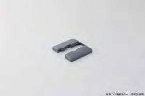


J95ZC-GR/NI/BC Mounting Plate Cover Sold Separately (See p.288)

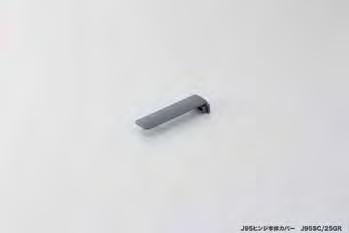
Plate sold
J95SC-16GR/NI/BC Safety Cover Sold Separately (See p.288)
(1-3/16")
*Mounting Plate sold separately. *If the door thickness is over 30mm (1-3/16") the door will need to be chamfered.
Nickel (NI)
Black Nickel (BN)
HEAVY DUTY

CONCEALED HINGE (16mm OVERLAY)
• Load capacity:

J95-24/16T,J95-C24/16T
• Maximum door width: 800mm (31-1/2" ) / 2pcs, 900mm (35-7/16" ) / 3pcs.
• Load capacity: 25 kg (55 Ibs)/2 pcs, 40 kg (88 lbs)/3 pcs.
Load capacity: 55 Ibs (25 kg)/2pcs, 88 lbs (40 kg)/3pcs.
• Clip on type for easy installation.
• 3-way adjustment with door installed.
• Maximum door width: 800 mm (31-1/2")/2 pcs, 900 mm (35-7/16")/3 pcs.
• Clip on type for easy installation.
Max. door width: 31-1/2" (800 mm)/2 pcs, 35-7/16" (900 mm)/3 pcs. Clip on type for easy installation. 3-way adjustment with door installed. Requires 6 M5 or equivalent (US#10) screws: 2 pcs for each hinge, and Optional hinge cover and mounting plate cover available (see pgs. 148-149). Glass face plate required for glass door application (see pgs. 148-149).
• 3-way adjustment with door installed.
• Requires 6 M5 or equivalent (US#10) screws: 2 pcs for each hinge, and 4 pcs for each mounting plate.

J95-C24/16T-NISelf-Closing 143
J95-24/16T-BNFree Swing 131
J95-C24/16T-BNSelf-Closing 143
J95-P6T Mounting Plate (sold separately p.288).
J95-24/16T-BNFree
J95-C24/16T-BNSelf-Closing
• Optional hinge cover (J95SC-25GR) and mounting plate cover (J95ZC-GR) available.
• Requires 6 M5 or equivalent (US#10) screws: 2 pcs for each hinge, and 4 pcs for each mounting plate.
• Optional hinge cover (J95SC-16) and mounting plate cover (J95ZC) available (sold separately p.288).
• For glass door applications, see page 285.


J95ZC-GR/NI/BC Mounting Plate Cover Sold Separately (See p.288)


J95SC-16GR/NI/BC Safety Cover Sold Separately (See p.288)

Part NameMaterial
Cup Zinc Alloy
Body Steel
Nickel (NI) Black Nickel (BN)
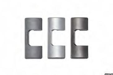

MOUNTING PLATE J95-P6T
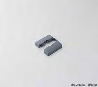
MOUNTING PLATE COVER

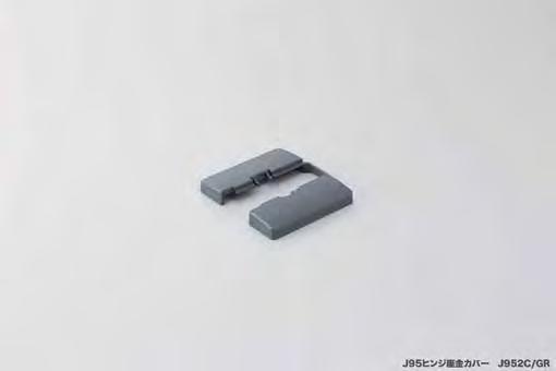
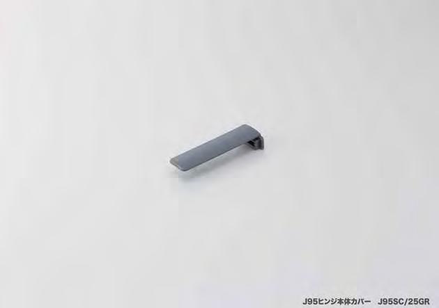
Special cover for J95 hinges to hide the screws. Comes with a double-sided tape to bond the cover and hinge. Please make sure that the surface is clean
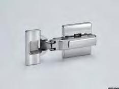
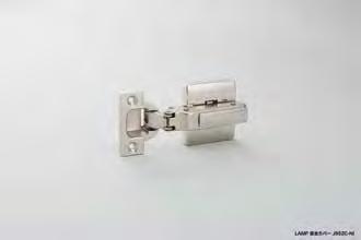
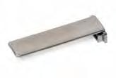
Hinge safety cover for J95 series. Specify finish when ordering.
GLASS FACEPLATE FOR J95 SERIES


Glass faceplates for J95 series. Specify finish when ordering.
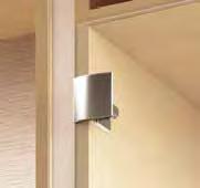
GLASS FACEPLATE FOR J95 SERIES


Glass faceplates for J95 series. Customizable design. Specify finish when ordering.
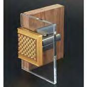
GH-J95FP-Q1/BL
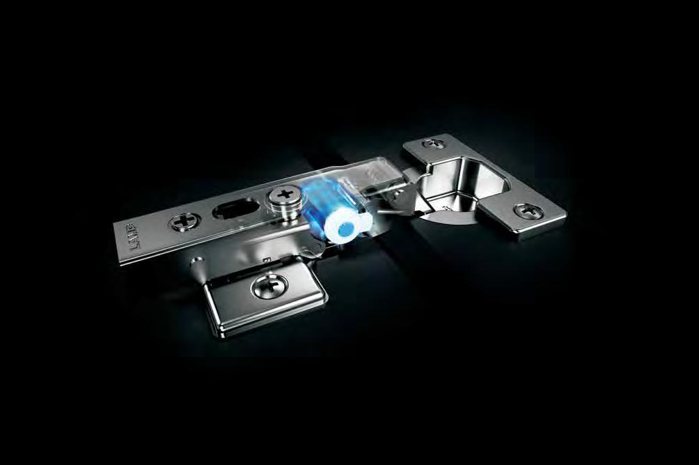

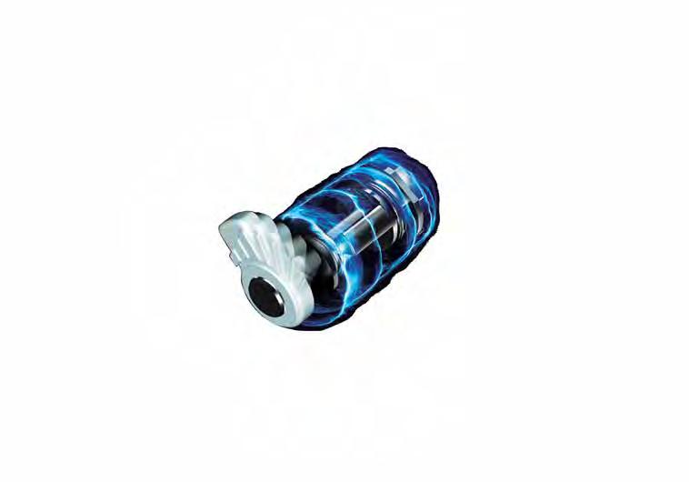
This is the rst time Sugatsune's unique Lapcon technology has ever been used inside a concealed hinge. The innovative rotary damper is not only extremely compact with a sleek overall design, but its force can also be adjusted to perfection in 5 steps, regardless of the door size or weight. 5-speed adjustable soft-close. The first Sugatsune concealed hinge ever built with Lapcon technology.
With damper function (5 levels), 105° and 85° opening
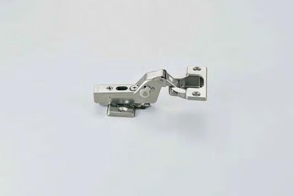

5-speed damper power adjustment lever
Drawings show a hinge, face plate and 360-P4W-30T mounting plate (sold separately).
Opening Clearance (O.C.)
Clearances for door edge O.C. (A) and hinge side O.C. (B) are necessary. O.C. (A) and (B) change depending on door thickness and bore distance (C). Refer to locus chart and tables below when designing cabinets.
Opening clearance (B), door thickness (D) and bore distance (C) relationship
• The table above shows O.C. (B) for C1 chamfering (chamfer plane).
* Please refer to the locus chart if door thickness is over 20mm. O.C. (B) can be made smaller by R chamfering (round chamfer) and C chamfering (chamfer plane) on the door.
Face frame cabinet bracket (FFCB-HG-1) not designed to work
Locus chart S=1/1
5-speed damper power adjustment lever With damper function (5 levels), 105° and
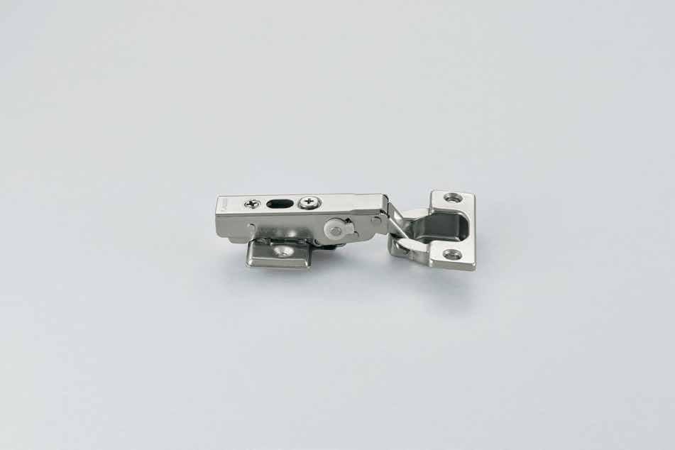
3-Way adjustment
Depth: +1.5, -2.5mm, Vertical: ±2.5mm, Overlay: +0, -4mm
Featuring 5-speed adjustable damper.
Load capacity: 13.2 Ibs (6 kg)/2 pcs, 22 lbs (10 kg)/3 pcs.
Max. door width: 23-5/8" (600 mm).
Max. door thickness: 13/16" (20 mm)
Clip on type for easy installation.
3-way adjustment with door installed. Mounting plate sold separately.
Successfully passed 200,000 cycles test.
Face frame cabinet bracket (FFCB-HG-1) required to install 360 Olympia overlay hinge on face frame cabinets. 1 bracket per hinge needed.
FFCB-HG-1 is sold separately per piece.
C1
Drawings show a hinge, face plate and 360-P4W-30T mounting plate (sold separately).
Opening Clearance (O.C.)
Clearances for door edge O.C. (A) and hinge side O.C. (B) are necessary. O.C. (A) and (B) change depending on door thickness and bore distance (C). Refer to locus chart and tables below when designing cabinets.
Opening clearance (B), door thickness (D) and bore distance (C) relationship Cut out dimensions (wooden doors)
• The table above shows O.C. (B) for C1 chamfering (chamfer plane).
* Please refer to the locus chart if door thickness is over 20mm. O.C. (B) can be made smaller by R chamfering (round chamfer) and C chamfering (chamfer plane) on the door.
close (5 levels)
360-26-19T85
Locus chart S=1/1
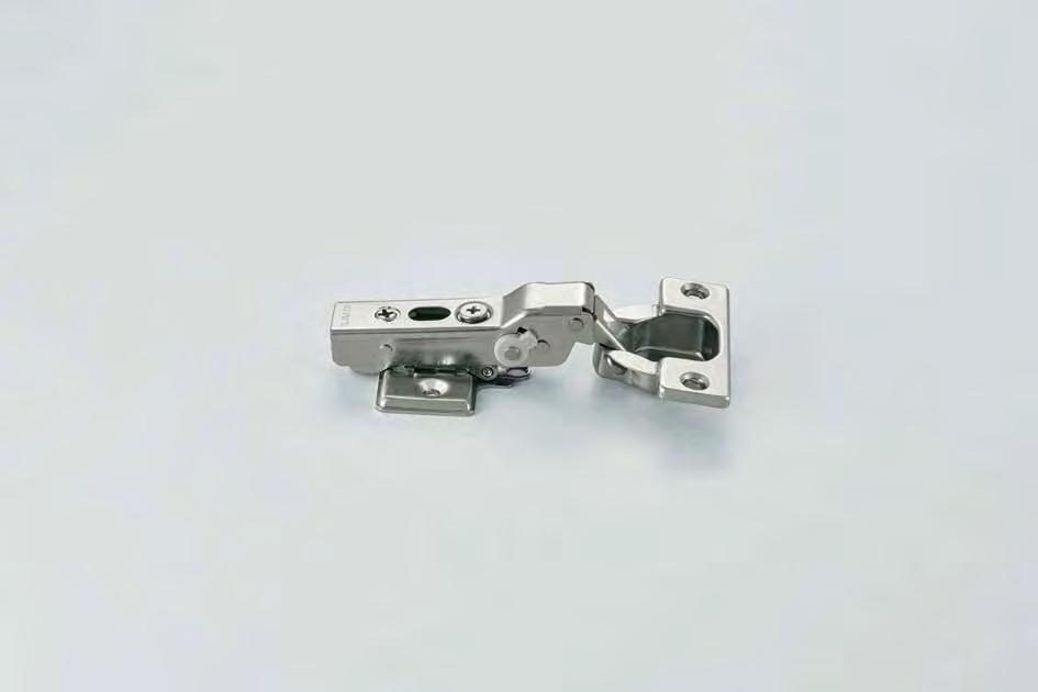
3-Way adjustment
Depth: +1.5, -2.5mm, Vertical: ±2.5mm, Overlay: +0, -4mm
Featuring 5-speed adjustable damper.
Load capacity: 13.2 Ibs (6 kg)/2 pcs, 22 lbs (10 kg)/3 pcs.
Max. door width: 23-5/8" (600 mm).
Max. door thickness: 13/16" (20 mm)
Clip on type for easy installation.
3-way adjustment with door installed. Mounting plate sold separately.
Successfully passed 200,000 cycles test.
Face frame cabinet bracket (FFCB-HG-1) required to install 360 Olympia overlay hinge on face frame cabinets. 1 bracket per hinge needed.
FFCB-HG-1 is sold separately per piece.
Drawings show a hinge, face plate and 360-P4W-30T mounting plate (sold separately).
Opening Clearance (O.C.)
Clearances for door edge O.C. (A) and hinge side O.C. (B) are necessary. O.C. (A) and (B) change depending on door thickness and bore distance (C). Refer to locus chart and tables below when designing cabinets.
Opening clearance (B), door
(D) and bore distance (C)
• The table above shows O.C. (B) for C1 chamfering (chamfer plane).
* Please refer to the locus chart if door thickness is over 20mm. O.C. (B) can be made smaller by R chamfering (round chamfer) and C chamfering (chamfer plane) on the door.
Locus chart S=1/1
(9 mm overlay)
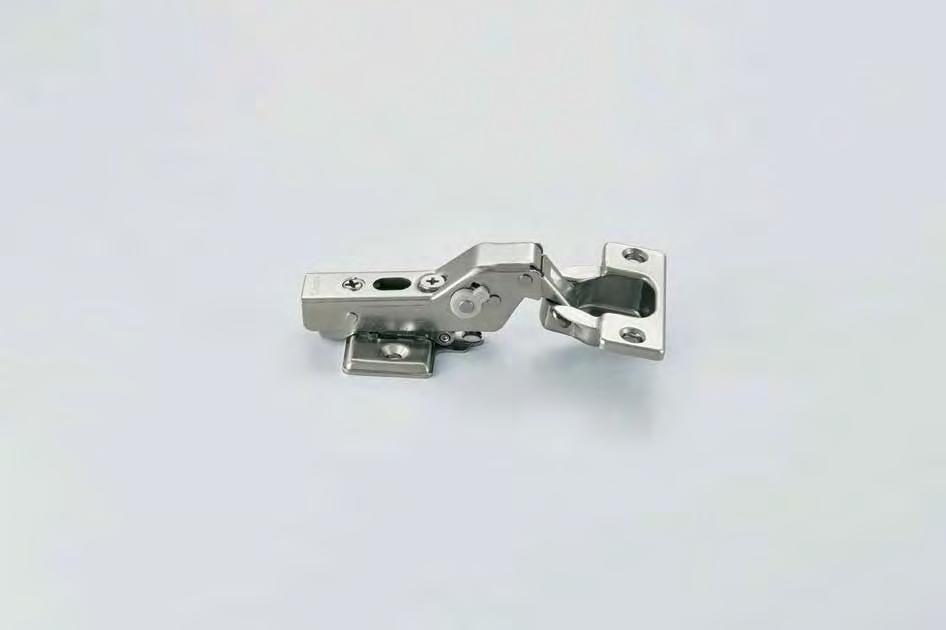
5-speed damper power adjustment lever
With damper function (5 levels), 105° and 85° opening
Featuring 5-speed adjustable damper.
Load capacity: 13.2 Ibs (6 kg)/2 pcs, 22 lbs (10 kg)/3 pcs.
Max. door width: 23-5/8" (600 mm).
Max. door thickness: 13/16" (20 mm)
Clip on type for easy installation.
3-way adjustment with door installed. Mounting plate sold separately.
Successfully passed 200,000 cycles test.
Face frame cabinet bracket (FFCB-HG-1) required to install 360 Olympia overlay hinge on face frame cabinets. 1 bracket per hinge needed.
FFCB-HG-1 is sold separately per piece.
Drawings show a hinge, face plate and 360-P4W-30T mounting plate (sold separately).
Opening Clearance (O.C.)
Clearances for door edge O.C. (A) and hinge side O.C. (B) are necessary. O.C. (A) and (B) change depending on door thickness and bore distance (C). Refer to locus chart and tables below when designing cabinets.
Opening clearance (B), door thickness (D) and bore distance (C) relationship
• The table above shows O.C. (B) for C1 chamfering (chamfer plane).
* Please refer to the locus chart if door thickness is over 20mm. O.C. (B) can be made smaller by R chamfering (round chamfer) and C chamfering (chamfer plane) on the door.
Cut out dimensions (wooden doors)
Installation drawing
Locus chart S=1/1
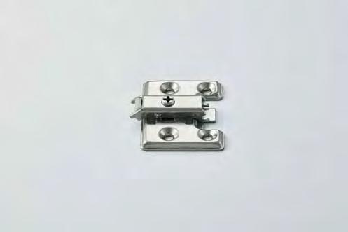

(19MM OVERLAY)
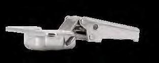
CONCEALED HINGE (14MM OVERLAY)
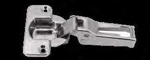
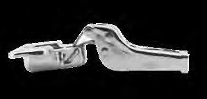
MOUNTING PLATE FOR 304B SERIES HINGES
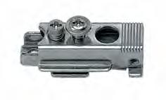
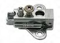
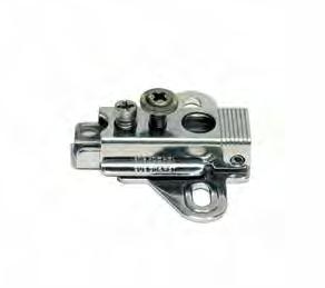
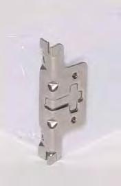
P4A/32
P4A/32-3W • Mounting plate for 304B hinges
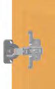
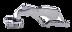
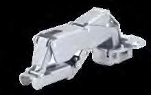
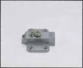
SLU-ELAN SWING LIFT-UP STAY
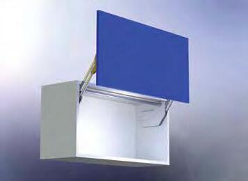
Simple Installation
Guide plate installation
Lapcon stay for SWING LIFT-UP DOORS.
Lift-assist mechanism for extra light-opening. Free stop feature.
Damper equipped for soft & quiet closing at the end.
Simple installation by mounting guide plate and sliding in main body. No hinges are required.
Connecting bar stays on in a fixed location for maximum space inside cabinet.
Recommended door size and weight :
Max. width: 59" (1500 mm)
Height: 15-3/8" ~ 19-11/16" (390 ~ 500 mm)/Door
Weight: 11 ~ 24.2 lbs (5 ~ 11 kg)/Door
Body installation
Connection bar installation
lbs (6.5 - 8.0 kg) SLU-ELAN-M4 17.6~20.9 lbs (8.0 - 9.5 kg)
SLU-ELAN-H4 20.9~24.2 lbs (9.5-11.0 kg)
*Min. inside cabinet height is 360mm (14-3/16") *Door weight includes handle.
■ Connecting Bar (Sold separately)
~
(856-866 mm) ELB-1080 47-1/4" (1200 mm)
~ 45-7/8" (1156-1166 mm) ELB-1380 59" (1500 mm)
*Please specify the compartment width when ordering.
~ 57-3/4" (1456-1466 mm)
VERTICAL SWING DOWN MECHANISM
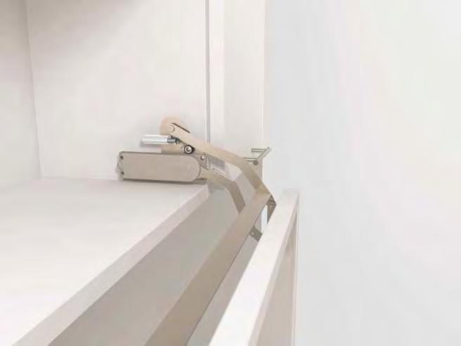
Patented LAPCON technology provides a smooth and quiet motion
Unique swing down mechanism will hold doors at the open position. Sleek & compact design.
Easy installation.
Adjustable arm mounting plate
Successfully passed 30,000 open/close private cycle tests.
Recommended door size and weight: Width: 23-5/8" ~ 35-7/16" (600 ~ 900 mm) Height: 14-1/8" ~ 15-3/4" (360 ~ 400 mm) Weight: 6.6 ~ 13.2 lbs (3 ~ 6 kg)
(835 mm (32-7/8")) included unless specified.
VERTICAL SWING LIFT UP MECHANISM
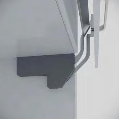

For taller, heavier upward-opening doors.
Soft closes to prevent slamming
The spring gently lifts the door after pulling it forward 4-3/4" ~ 5-15/16" (120 ~ 150 mm).
Adjustable lift-assist feature refines the opening force to best match your door’s size and weight.
Adjustments are easily accessible making maintenance simple 3-Way adjustability:
Vertical +/- 1/4" (6 mm)
Horizontal +/- 1/8" (2.5 mm)
Tilt +/- 5º
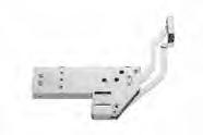

Image
1-15/16" (49 mm) 1-5/16" (33.5 mm) 1-5/16" (33.5 mm)
(195 mm)
(30 mm)
(153 mm)
(161 mm)
How to Order:
1) Select a body.
2) Select a body cover.
3) Select a Connecting Bar.
*1: If not using a gasket/door stopper, please shift the body 3/16" (4 mm) towards the back panel.
*2: The maximum door protrusion when opening and closing is approximately 13-1/2" (343 mm).
*3: Total travel of door is 24-1/8" (613 mm).
Cover (Sold separately)
Connecting Bar (Sold separately)
Body Cover (Sold Seperately)
This product is sold as 1 set. The order quantity is "1", which includes one piece of the left and right.
• The Connecting Bar comes in three lengths, for door widths of 23-5/8" (600 mm), 291/2" (750 mm), and 35-7/16" (900 mm).
• Use the standard length Connecting Bar when the door overlay on the side panel is 9/16" (15 mm). For door overlays exceeding 9/16" (15 mm), cut the Connecting Bar to length using the calculation formula provided below.
Length of the Connecting Bar = Door width - (Overlay x 2) - 1-3/8" (35 mm) Or, please calculate as follows below.
Length of the Connecting Bar = Cabinet internal width - 1-3/8" (35 mm)
Mounting Plate
Damper HolderPolyacetal (POM)Natural ➄ Adjustment ScrewSteel (SWRM)Bright Chromate
Body Connecting Bar (Sold separately)
This product is sold as 1 set. The order quantity is "1", which includes one piece of the left and right.
VERTICAL SWING LIFT UP MECHANISM
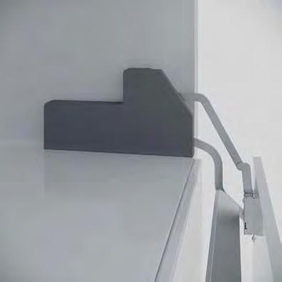
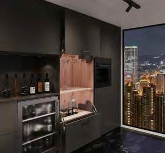
For taller, heavier downward-opening doors.
Unique swing down mechanism.
The spring gently opens the door after pulling it forward 4-3/4” ~ 5-15/16” (120 ~ 150 mm).
Soft closes to prevent slamming
Adjustable lift-assist feature refine’s the opening force to best match your door’s size and weight.
Adjustments are easily accessible making maintenance simple 3-Way adjustability:
Vertical +/- 1/4” (6 mm)
Horizontal +/- 1/8” (2.5 mm)
Tilt +/- 5º
Body


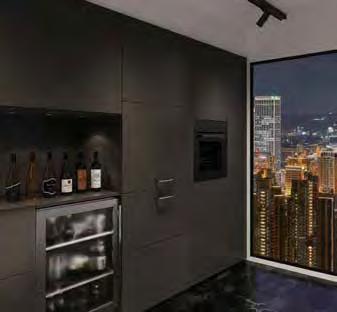
4 (Gasket/Door stopper)*1
16-5/8" (423 mm) Fitting of metal parts
(198
(110 mm)
(15 mm)
(37.5 mm) 13-1/16" (332 mm)
(363 mm) 5-1/8" (130 mm)
(37 mm)
*1: If not using a gasket/door stopper, please shift the body 3/16" (4 mm) towards the back panel.
*2: The maximum door protrusion when opening and closing is approximately (250 mm). *3:
Body Cover (Sold separately)
Maximum Projection 9-3 /4" (250 mm)

Body Cover (Sold Seperately)
How to Order:
1) Select a body.
2) Select a body cover.
3) Select a Connecting Bar.
• The Connecting Bar comes in three lengths, for door widths of 23-5/8" (600 mm), 291/2" (750 mm), and 35-7/16" (900 mm).
• Use the standard length Connecting Bar when the door overlay on the side panel is 9/16" (15 mm). For door overlays exceeding 9/16" (15 mm), cut the Connecting Bar to length using the calculation formula provided below.
Length of the Connecting Bar = Door width - (Overlay x 2) - 1-3/8" (35 mm) Or, please calculate as follows below.
Length of the Connecting Bar = Cabinet internal width - 1-3/8" (35 mm)
MaterialFinish/ Color ➀ Body Steel (SPCC)Nickel ➁ Arm ➂ Mounting Plate ➃ Damper HolderPolyacetal (POM)Natural ➄ Adjustment ScrewSteel (SWRM)Bright Chromate
This product is sold as
Body Connecting Bar (Sold
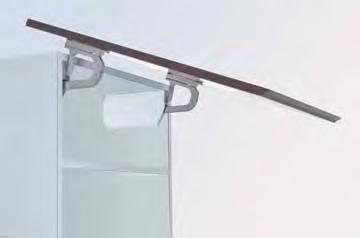
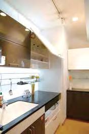
3 functions on 1 stay
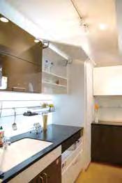
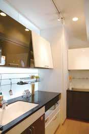
Lapcon stay for UPWARD-OPENING FLAP DOORS. Door opens over the cabinet. (Space of 4-5/16" is required over cabinet)
Lift-assist mechanism for extra light-opening. Door stays in any desired position.
Damper equipped for soft & silent closing at the end. Slim design and installed location maximizes space inside of cabinet.
Simple installation by aligning body to edge of cabinet. No hinges/connecting bar needed.
Door height adjustable. (Horizontal ±1/16", Vertical ±1/16")
Successfully passed 30,000 open/close private cycle tests.
Recommended door size and weight:
Max. width: 47-1/4" (1200 mm)
Height: 19-11/16" ~ 29-1/2" (500~750 mm)/Door
Weight: 11 ~ 27.5 lbs (5 ~ 12.5 kg)/Door
Sold in pairs


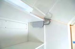
No connecting bar or hinges are necessary
2. Free stop
1. Lift-assist
3. Soft-close
■ Door Weight Range Table (lbs.) Per Pair
21.421.426.2
20.620.625.3
18.218.222.3
■ Lifting power
Door height (inch) x (Door weight (lbs) -1)
HBFN
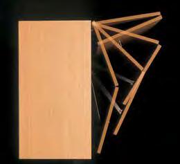
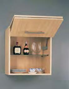
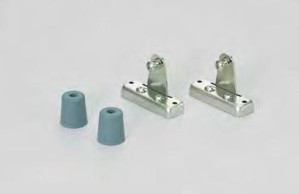
HORIZONTAL BI-FOLDING DOOR MECHANISM
• HBFN's unique bi-fold door mechanism will assist in opening and closing doors in a smooth motion.
• The mechanism is compact, with no tracks or guides
• Easy installation.
• Patented Lapcon technology of fers smooth and quiet motion.
• Successfully passed 30,000 open/close private cycle tests.
Designed to operate at room temperature 0°~40°C (32°~104°F).
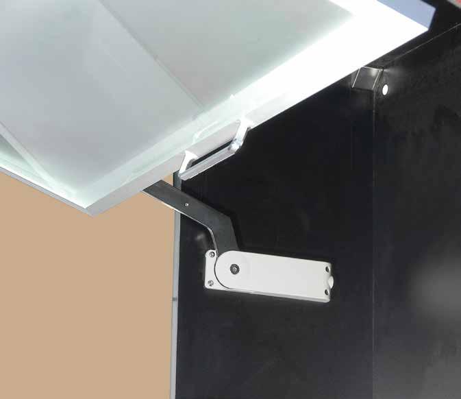
Unique new bi-fold door mechanism will assist in opening and closing doors in a smooth motion. No tracks or guides required. Handle position can be at the bottom of the door Arm length adjustable for various door sizes. Patented LAPCON technology provides very smooth and quiet motion.
Recommended Door Size and Weight:
Width, 450~900 mm (17-23/32"~35-7/16")
Height, 320~370mm (12-19/32"~14-9/16")/ea
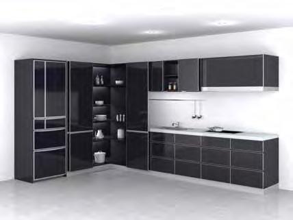
Door Width
15-3/4" ~ 19-11/16" (400 ~ 500 mm)
21-5/8" ~ 25-9/16" (550 ~ 650 mm)
Door Height 23-5/8" ~ 94-1/2" (600 ~ 2400 mm)
Door Thickness 5/8" ~ 15/16" (15 ~ 24 mm)
Door Weight *Max 37.4 lbs (17 kg)*Max 52.8 lbs (24 kg)
*Max door weight will vary depending on number of hinges used.
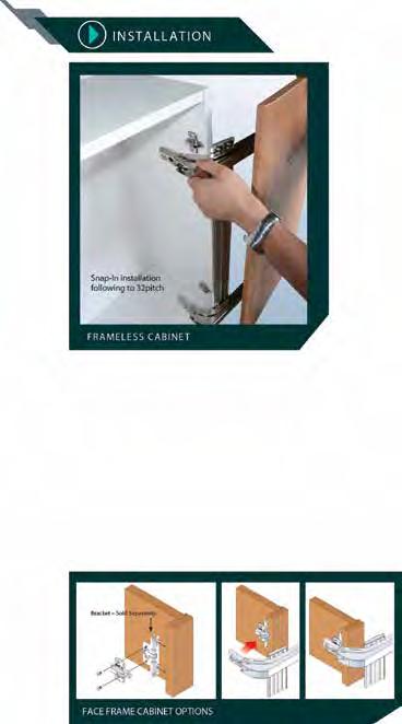
Lateral Swing Mechanism
Allows doors to swing out laterally in a small radius, ideal for tight front space application.
Full Access to Cabinet
Door will not get in the way when fully opened providing full access to the cabinet.
Free Swing & Soft-close
Easy Installation
Designed for standard 32 mm system mounting, with snap-on hinge.
4-Way Adjustable
3-way adjustable like concealed hinges and also with parallel adjustment. Various Applications
Can be used in single or double door configuration. Ideal for cabinets in kitchen, bathroom, laundry room etc. *For overlay use.
LIN-X450
LIN-X600
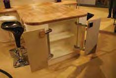
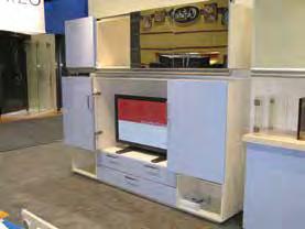
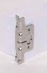
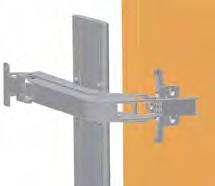
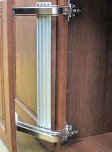
Face Frame Bracket
Corner (Inside) Kitchen Corner (Outside)
LATERAL OPENING DOOR SYSTEM
Standard Kit
Door Width
15-3/4" ~ 19-11/16" (400 ~ 500 mm)
Door Height 23-5/8" ~ 35-7/16" (600 ~ 900 mm)
Door Thickness 5/8" ~ 15/16" (15 ~ 24 mm)
Door Weight Max.15.4 lbs (7 kg) / Door
Individual Parts for Tall / Heavy Door
Door Preparation
Hinge in middle should be positioned at or equally distributed from center of door. *Can be used on heavier / taller doors by adding hinge arms. Please see below for details.
Door Width
15-3/4" ~ 19-11/16" (400 ~ 500 mm)
Door Height 23-5/8" ~ 94-1/2" (600 ~ 2400 mm)
Door Thickness 5/8" ~ 15/16" (15 ~ 24 mm)
Door Weight Max. 37.4 lbs (17 kg)
LIN-X450
3/4" (19 mm)
LIN-X450+535/64" (14 mm)
Cabinet Preparation
Individual Parts - Ordering Chart
Ordering Info
Use corresponding letter in below table, and see “Parts Breakdown Table” for parts to be ordered.
23-5/8"~35-7/16" (600~900 mm)
(901~1200 mm)
(1201~1500 mm)
59-3/64"~70-7/8" (1501~1800 mm)
(1801~2100 mm)
82-11/16"~94-1/2" (2101~2400 mm)
Parts Breakdown Table
LIN-X450ACD Single Arm ( with Damper )
LIN-X450A Single Arm ( without Damper )
230-P4W-32T (for 19 mm overlay) or 230-P4W-32T+5 (for 14 mm overlay)
Mounting Plate
*Requires 3 pcs of TAP3515NI Screw 3.5 × 15NI (Sold separately) per Mounting Plate
LIN-X450-L540 Connecting Bar L=540 mm
LIN-X450-L840 Connecting Bar L=840 mm
LIN-X450-L1140 Connecting Bar L=1140 mm
LIN-X450-L1440 Connecting Bar L=1440 mm
LIN-X450-L1740 Connecting Bar L=1740 mm
LIN-X450-L2040 Connecting Bar L=2040 mm
Door Width 21-5/8" ~ 25-9/16" (550 ~ 650 mm)
Door Height 23-5/8" ~ 35-7/16" (600 ~ 900 mm)
Door
Individual Parts for Tall / Heavy Door
Door Width 21-5/8" ~ 25-9/16" (550 ~ 650 mm)
Door Height 23-5/8" ~ 94-1/2" (600 ~ 2400 mm)
Door Thickness 5/8" ~ 15/16" (15 ~ 24 mm)
Door Weight
Individual Parts - Ordering Chart
Ordering Info
Use corresponding letter in below table, and see “Parts Breakdown Table” for parts to be ordered.
Door
23-5/8"~35-7/16" (600~900 mm)
35-7/16"~47-1/4" (901~1200 mm)
(1201~1500 mm)
59-3/64"~70-7/8" (1501~1800 mm)
(1801~2100 mm)
(2101~2400 mm)
Parts Breakdown Table
LIN-X600ACD Single Arm ( with Damper )
LIN-X600A Single Arm ( without Damper )
Mounting Plate
230-P4W-32T (for 19 mm overlay)
LIN-X60-L540
LIN-X60-L840
LIN-X60-L1140
LIN-X60-L1440
LIN-X60-L1740
*Requires 3 pcs of TAP3515NI Screw 3.5 × 15NI (Sold separately) per Mounting Plate
Connecting Bar L=540 mm
Connecting Bar L=840 mm
Connecting Bar L=1140 mm
Connecting Bar L=1440 mm
Connecting Bar L=1740 mm
LIN-X60-L2040 Connecting Bar L=2040 mm
LIN-X60C End Cap for Connecting Bar
LATERAL OPENING DOOR SYSTEM
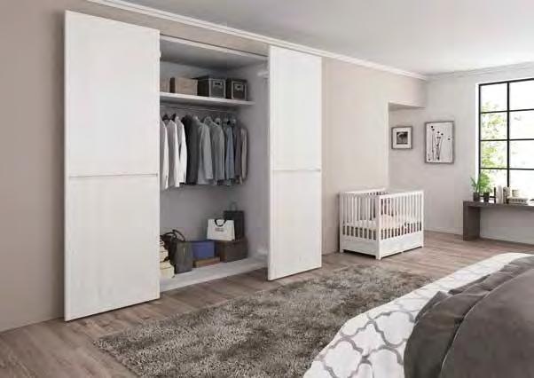
Lateral Opening Mechanism: Allows doors to swing out laterally in a small radius, ideal for tight front space application.
4-Way Adjustable: Vertical, horizontal, depth and parallel adjustment. Smooth Movement: Built-in dampers provide a smooth soft-closing movement. Use in various applications: Ideal for closet entryways, large pantry doors, storage, hidden rooms, etc. Can also be used on L shaped corner spaces. Hardware is non-handed: can be used for left- or right-opening doors. Designed for overlay installation, but can be installed flush with the surrounding cabinet or wall. Please contact customer service for details on inset installations.
*1 Height may be further details,
Installed to side wall, not interfering with taking in/out of articles.
Minimize opening clearance required with LIN-X800, compared to traditional swinging doors. When closed, the LIN-X door can be flush with the surrounding walls.
*2 Please en sure weight of the aluminium frame.
*3 Set the clea r ance For details, refer
Door does not get in the way when opening and closing.
Minimize opening clearance required with LIN-X1000, compared to traditional swinging doors. When closed, the LIN-X door can be flush with the surrounding walls.
Opening pr ojection is about half of s wing doo r. Door will be ush wit h surrounding walls when closed.
LIN-X800 LIN-X800H
Door Width 29-1/2" ~ 33-7/16” (750 ~ 850 mm)
Max. Door Height 94-1/2” (2400 mm)117-5/16” (2980 mm)
Door Thickness 15/16” ~ 1-9/16” (24 ~ 40mm)
Max. Door Weight 88 lbs (40kg) / door
In case of LIN-X1000
Adjustability
In case of swing door
Adjustable in vertical, horizontal, depth and parallel directions.
Installation Examples
Max. door width 1100mm (e ective opening width 930 mm) Soft close
ï Door closes smoothly and softly with damper. (Damping force 5-step adjustable)
ïDoor opens softly with damper.
Video Link
When Closed
Detailed Drawing
Range of Motion
With door width 800mm (25mm overlay at the leading edge and hanging side)
The dimensions in [ ] indicate LIN-X800H speci cations.
For cabinet interior dimensions smaller than the minimum value, reduce the other dimensions marked with *2 by an equivalent amount. The connecting rod must be cut by the customer.
OPENING DOOR SYSTEM
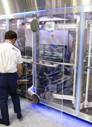
Item
LIN-X1000/WT-S 3/4" (19 mm) Steel, Aluminum White
LIN-X1000/BL-S Black
Door Width 29-1/2” ~ 43-5/16” (750 ~ 1100 mm)
Max. Door Height 117-5/16” (2980 mm)
Door Thickness 15/16” ~ 1-9/16” (24~40 mm)
Max. Door Weight 198 lbs (90 kg/door)
Lateral Opening Mechanism: Allows doors to swing out laterally in a small radius, ideal for tight front space application.
Heavy Duty: Max. weight 198 lbs.
4-Way Adjustable: Vertical, horizontal, depth and parallel adjustment.
Smooth Movement: Built-in dampers provide a smooth soft-closing movement. Use in various applications: Ideal for closet entryways, large pantry doors, storage, hidden rooms, etc.
Hardware is non-handed: can be used for left- or right-opening doors. Designed for overlay installation, but can be installed flush with the surrounding cabinet or wall. Please contact customer service for details on inset installations.
Innovative design internationally recognized with the following awards:
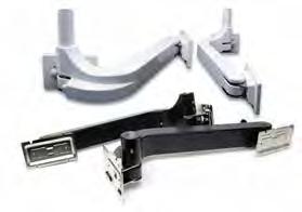
Minimize opening clearance required with LIN-X1000, compared to traditional swinging doors. When closed, the LIN-X door can be flush with the surrounding walls.
Adjustability
Adjustable in vertical, horizontal, depth and parallel directions.
Installation Examples
White/Black
White/Black
White/Black
White/Black
White/Black
If you know this logo, then you know us!
For more than 90 years Sugatsune has manufactured brand products while innovating unique movements, materials and designs.
Controlled & Seamless Multi-Linear Motion
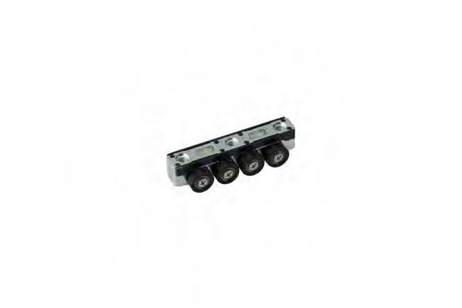
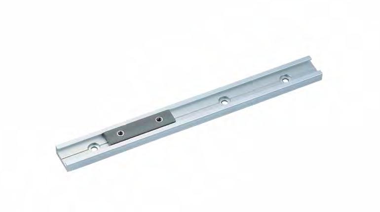
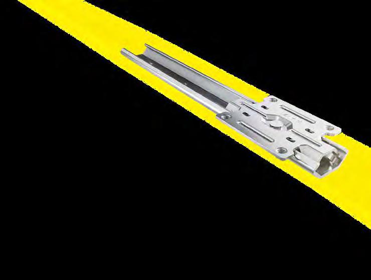
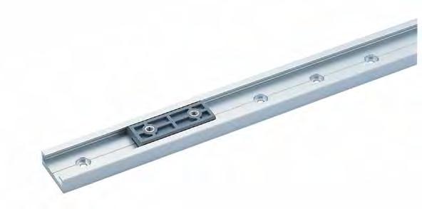
Ensures smooth guidance under multi-directional loading conditions.
LINEAR MOTION GUIDED BY ROLLERS AND BALLS
ELEVATE YOUR PERFORMANCE
with the MLGX Multi-Roller Linear Guide. Its unique “Dual-X design” features 45°angled roller bearings that create consistent contact with the rail, ensuring smooth and stable motion even when operating under a moment load. It can also be mounted in various orientations while maintaining its level of performance.
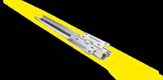
• The innovative "Dual-X" design:
- Smoothly facilitates up to 27 lbs (120 N) in vertical or horizontal application.
- Maintains smooth and consistent movement even when a moment load occurs.
- Can be used with a motor drive.
- Has a system life of 100 km & passed 500,000 cycle test.
• The guide block is preloaded to significantly reduce rattling.
• Multiple guide blocks can be used with a guide rail (rails and blocks ordered separately).
• Ideal for automated machinery, medical, analysis or food equipment and kiosks.

DUAL X STRUCTURE:
Designed to facilitate reliable movement in any direction.Rollers are located at two different angles to resist both horizontal and vertical loads.


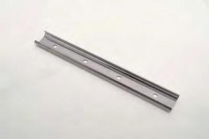
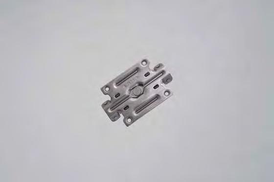
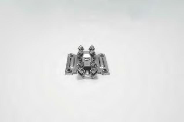
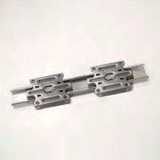


LINEAR GUIDE
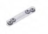

Smooth and high precision movement with its unique “multi-roller” design.
It can be used together with a motor drive.
Slim guide rail with width of 1/2” (13 mm).
Has a system life of 60 km and passed 300,000 cycle test.
Please use with stoppers
Common applications include medical equipment, food processing equipment, gaming and vending machines, analytical instruments, factory automation.


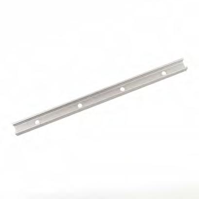
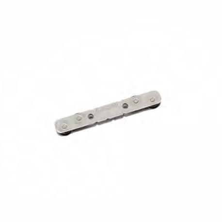
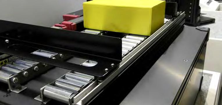
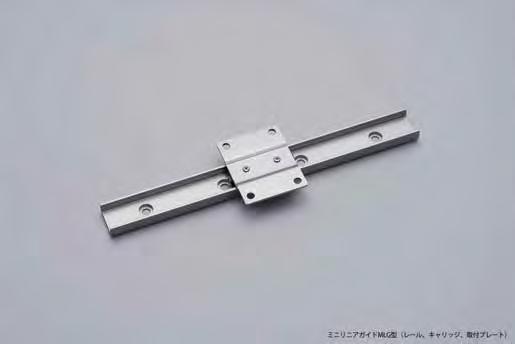
Combination Drawings
The guide rail, guide block, and mouting plate are used.
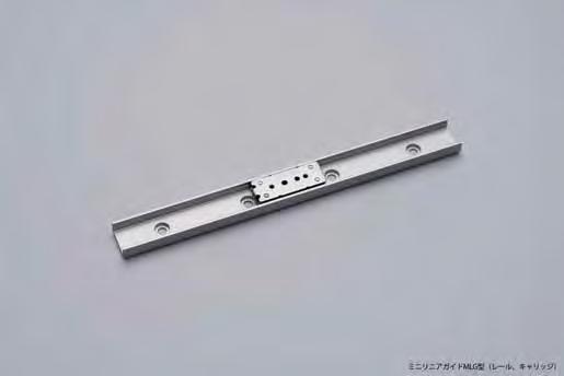
Smooth and high precision movement with the unique mechanism called “multi-roller”.
Please use with stoppers. Common applications include medical equipment, food processing equipment, gaming and vending machines, analytical instruments, factory automation.
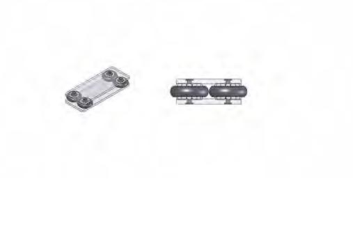
Ball bearings
Rollers
Thrust load
Radial load
The multi-roller mechanism makes it possible to have smooth movements even with loads applied in radial or thrust directions.
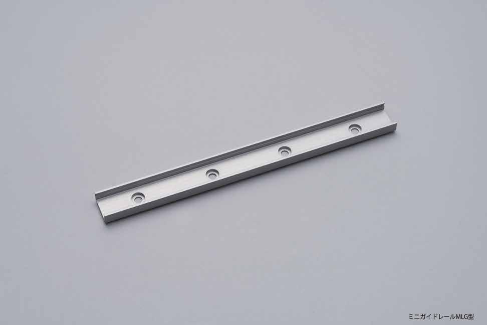
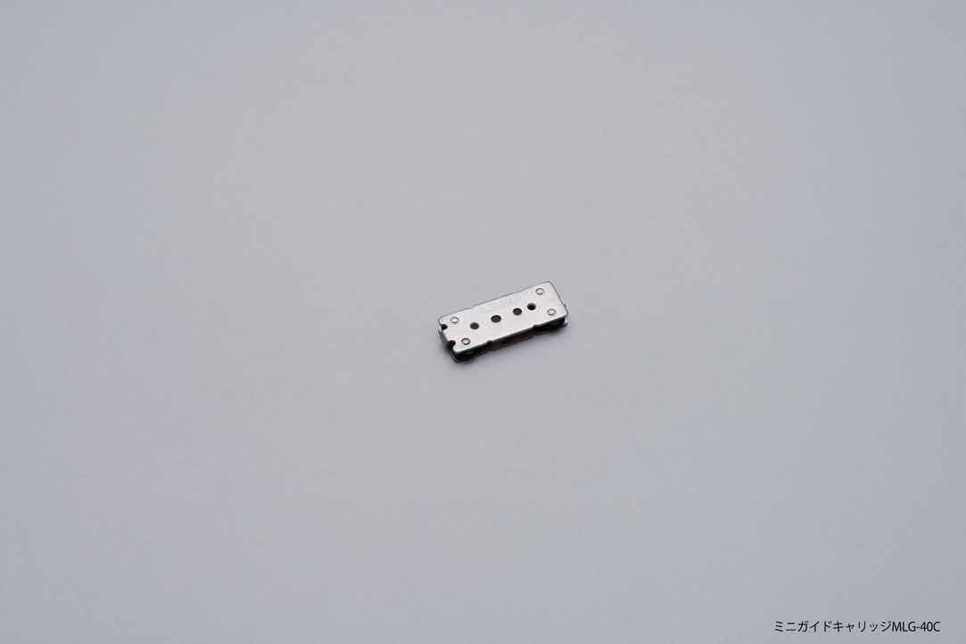
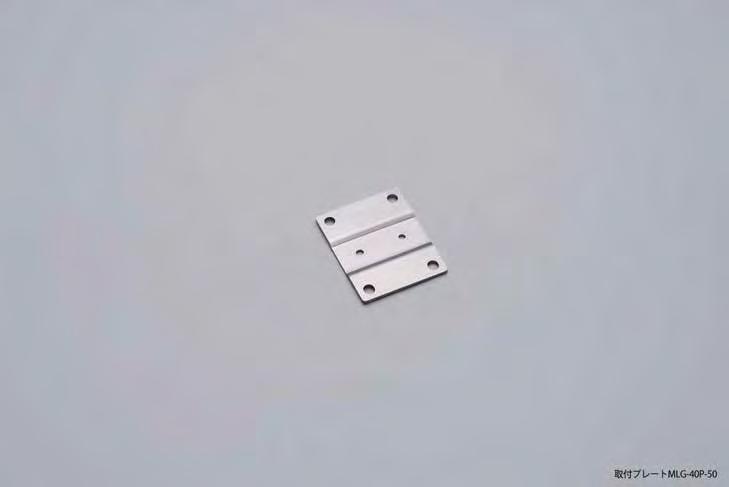
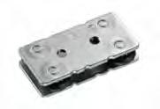
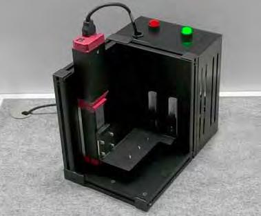
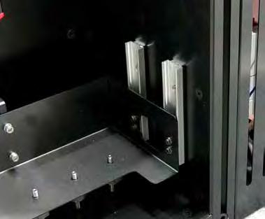
3/4 EXTENSION SLIDE (Undermount Type)
Under carriage mounting with bracket. 3/4 extension.
Front disconnect.
Friction brake stop.
Mount with M4 or #8 Binding, Pan, or Truss head screws.
Two plastic tacks supplied per slide.

ESR-2-2424-3/4" (628.6 mm)17-1/2" (444.5 mm)414.7 5.5 (12
ESR-2-26 26-3/4" (679.4 mm) 19-1/2" (495.3 mm)465.5
STAINLESS STEEL MINI GUIDE
STAINLESS STEEL MINI GUIDE
SCRL2-15S-100A
Thin

SCRL2-15S
Compact and slim profile allows the guide to be used for small and tight applications.
SCRL2-15S-80A 3-1/8” (80mm) do not have holes indicated with (*)

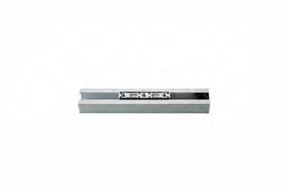
█ INSTALLATION : Guide rail, Roller Carriage, Stopper
Carriage with built-in bearing provides smooth movement. High durability and silence movement.
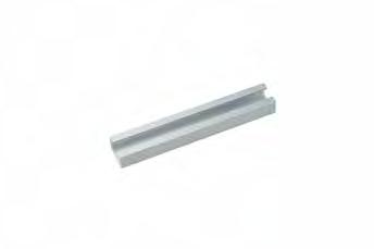
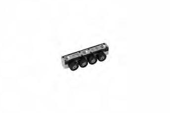
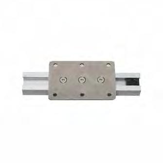
█ INSTALLATION : Guide rail, Roller Carriage, Stopper, Installation Plate


ROLLER CARRIAGE (LGB-30CM)

STOPPER (LGB30-ST)
GUIDE TRACK (LGB30)
STOPPER (LGB30-ST)
ROLLER CARRIAGE (LGB-30CM)
GUIDE TRACK (LGB30)
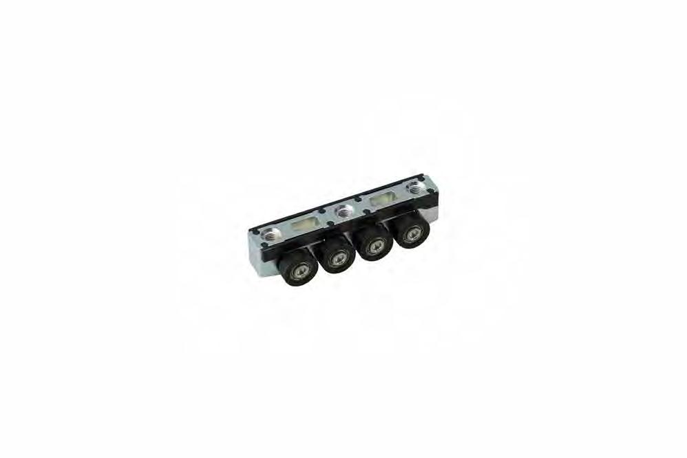
ROLLER CARRIAGE (Pre-loaded)
Linear guide roller carriage with bearing for smooth slide operation. To be used in the combination of LGB30 guide rail.
LGB-30CB
Linear guide roller carriage is pre-loaded in both directions for silent operation:
- Reduces rattling between the carriage and the rail.
- Ensures silent operation in both directions. To be used in combination with LGB30 guide rail.
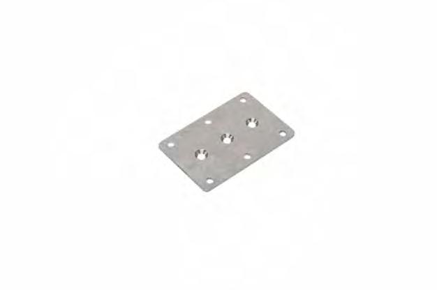
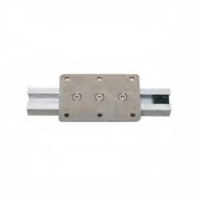
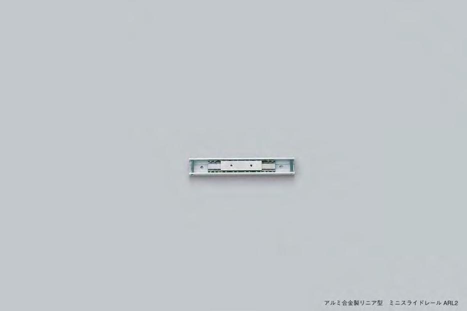
Two-way travel.
Thin
Designed
Thin
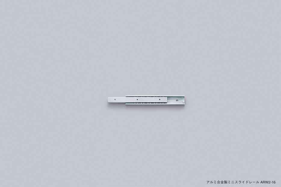
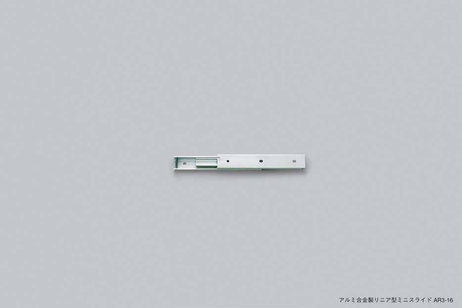
Full
Thin
Mounting plate attached type. Mount with M4 or #8 Binding, Pan, or Truss head screws.

No.Part NameMaterial
➀ Outer Rail
➁ Inner Rail
➂ Mounting Plate
➃ Retainer
➄ Balls
Stainless Steel

15, MR-15CS LOAD RATING INFORMATION
ends of rail are not anodized.
Perfect for small stroke application. No grease needed. Block and rail sold separately
Certain reduction needs to be applied depending on application or environment.
Low speed/Low operation frequency = 70% to 100% of Load Rating
Moderate speed/High operation frequency = 35% to 65% of Load Rating
High operation frequency with Vibration & Shocks = 10% to 30% of Load Rating
MRS

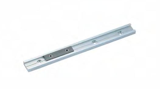
Perfect for small stroke application. No grease needed.
Block and rail sold separately
MRS20-1003-15/16" (100 mm)220
MRS20-2007-7/8" (200 mm)440
MRS20-40015-3/4" (400 mm)880
MRS20-80031-1/2" (800 mm)16160
MRS20-200078-47/64" (2000 mm)40400
■ Reduction Factor
Certain reduction needs to be applied depending on application or environment.
Low speed/Low operation frequency=70% to 100% of Load Rating
High operation frequency with Vibration & Shocks=10% to 30% of Load Rating Horizontal Static Load Fx
Moderate speed/High operation frequency=35% to 65% of Load Rating
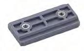
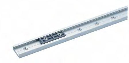
Perfect for small stroke application. No grease needed.
MRS 30, MR-50C LOAD RATING INFORMATION
Dynamic Friction Coefficient:1
Maximum PV (Pressure (kgf-mm2) x Velocity (m/min.))=3.06
MRS30-1003-15/16" (100 mm)10220
MRS30-2007-7/8" (200 mm)
440 MRS30-40015-3/4" (400 mm) 880100
MRS30-80031-1/2" (800 mm)1616080
MRS30-200078-47/64" (2000 mm)4040030
Horizontal Static Load Fx
Vertical Static Load Fy 15.0 kgf (33.0 lbs)
Vertical Dynamic Load Mx
Horizontal Dynamic Load My
Horizontal
■ Reduction Factor
Certain reduction needs to be applied depending on application or environment.
Low speed/Low operation frequency=70% to 100% of Load Rating
Moderate speed/High operation frequency=35% to 65% of Load Rating
High operation frequency with Vibration & Shocks=10% to 30% of Load Rating
Polyethylene resin with excellent sliding properties eliminates the need for grease or oil. Polyethylene resin has a high chemical resistance. UL94 HB grade flame resistance. Block and rail sold separately.
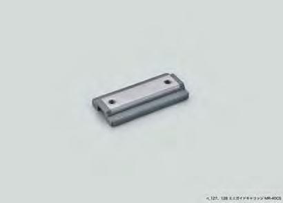
2-3/4" (70 mm) 1-31/32" (50 mm)
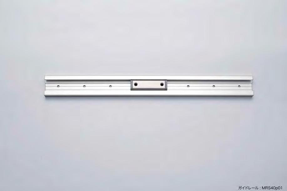
(25 mm)
(70 mm) 1-31/32" (50 mm) 1-31/32" (50 mm)
Combination Dimensions for Guide Rail & Carriage
(34.7 mm)
(20 mm)
(25 mm)
(3.5 mm)
(40 mm)
(20 mm)
(12 mm)
(7.7 mm)
(11 mm)
(2.8 mm)
ADJUSTABLE MOUNTING UNIT
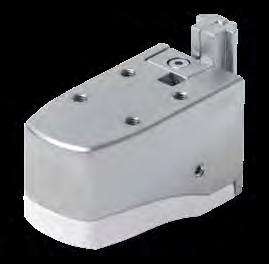

Holds at any height on aluminium frames. The cover prevents unintentional lock release. Designed for use with the FSL-L, an aluminium frame. The cover prevents unintentional lock release. The locking mechanism prevents only downward motion. Can be installed to an aluminium frame that is already assembled. A monitor can be mounted on the FSL-V36 when used with the FSL-MB, an optional monitor-mounting bracket.


Open the cover and push the lever to move the unit up or down. The unit stops where the lever is released.
Insert the body into the aluminium frame while pushing the lever.
Mount the guide piece to the unit. Secure with hex bolts.
Mount guide piece to unit

MONITOR MOUNTING BRACKET

Application

Used with FSL-V36 and KA-T100S50
• KA-T100S50, Monitor Mount
*Angle adjustment: 180° swiveling, and 40° tilting
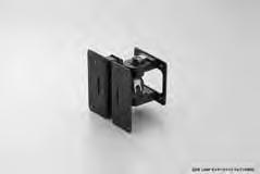


AD-KH

How to select components such as Lapcon stays and torque hinges?
Sasuga-kun can address such concerns!!

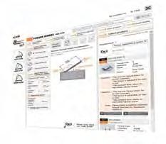
It 's a web-based tool that can automatically calculate the torque required and select (※) suitable hinges, stays and other products, simply by entering the movement, size, weight and centre of gravit y of a door


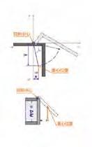

9/64 3.629.054.4 79.8 105.2130.6156.0181.4206.8232.2
283.0308.4 5/32 4.029.454.880.2105.6131.0156.4181.8 207.2 232.6258.0283.4308.8 11/64
3/16
4.429.855.280.6106.0131.4156.8182.2 207.6 233.0258.4283.8309.2
4.830.255.681.0106.4131.8 157.2 182.6208.0233.4258.8284.2309.6 13/64 5.230.656.081.4106.8132.2 157.6 183.0208.4233.8259.2284.6310.0
7/32
5.631.056.481.8 107.2 132.6158.0183.4208.8234.2259.6285.0310.4 15/64
6.031.456.882.2 107.6 133.0158.4183.8209.2234.6260.0285.4310.8 1/4 6.431.8 57.2 82.5108.0133.4158.8184.2209.6235.0260.4285.8311.2 17/64 6.7 32.1 57.5 82.9108.3 133.7 159.1184.5209.9235.3 260.7 286.1311.5 9/32 7.1 32.5 57.9 83.3 108.7 134.1159.5184.9210.3 235.7 261.1286.5311.9 19/64 7.5 32.958.3 83.7 109.1134.5159.9185.3
8.7 34.159.584.9110.3 135.7 161.1186.5211.9 237.3262.7 288.1313.5 23/64 9.134.559.985.3 110.7 136.1161.5186.9212.3 237.7 263.1288.5313.9 3/8 9.534.960.3 85.7
15/32 11.9 37.362.7
1.8504
Measurement Conversions
inch = mm ÷ 25.4 mm = inch x 25.4
*All tools and figures are for reference only. cmmminchfeet 110 0.3940.0328 0.1 1 0.03940.00328 2.5425.4 1 0.083 30.48304.8 12 1
DISCLAIMER:
Specifications, features, illustrations, certifications and materials shown in this catalog are based upon the latest available information at the time of publication. Although descriptions are believed to be correct, accuracy cannot be guaranteed. Sugatsune reserves the right to make changes at any time, without notice or obligation, in finishes, materials, sizes, specifications and availability and disclaims any and all liability for typographical, printing or production errors or changes affecting the products and/or specifications contained herein. \Actual performance of products may vary based upon many factors and may be less than stated. Differences in construction and build materials, designs or configurations may affect product performance and therefore, the customer is solely responsible for making the final selection of the product(s) to be used and to assure that all performance, safety and warning requirements of the application are satisfied.

