
OVERVIEW
This document provides an overview of functional details of beadlock wheels, general recommended assembly and disassembly procedures, and safety precautions to be observed during assembly and when used on a vehicle. Assembly and installation must be done by a trained professional. Custom Wheel House is not responsible for product damage, vehicle damage, or personal injury due improper assembly or installation by an untrained person.
BEADLOCK WHEEL CHARACTERISTICS
For the purpose of this document a beadlock wheel will be considered to be an assembly made up of a wheel with beadlock flange, a beadlock ring used to apply clamping force to the outside tire bead, and a set of bolts that generate the clamping force. Alternate types of beadlock wheels manufactured for other industries or by other companies will not be covered in this document. See figure below which details the system components.
A standard wheel relies solely on tire inflation pressure to maintain a seal between the tire bead and rim. A beadlock wheel is different from a normal wheel in that it relies on clamping force generated by the tightening of a set of bolts that thread into the wheel and apply force to the beadlock ring which mechanically clamps and seals the tire’s outer bead to the wheel.

FIG 1: BEADLOCK WHEEL COMPONENTS: GREY IS WHEEL, ORANGE IS BEADLOCK RING, RED IS CLAMP BOLT, GREEN IS WASHER.
The main advantage of a beadlock wheel over a standard wheel is that the seal between the tire and wheel is maintained independent of inflation pressure. This is a characteristic that is beneficial for off road use where lower inflation pressures are used to improve traction by enlarging the tire contact patch on loose surfaces and reducing ride harshness felt while traveling on rough terrain by reducing the effective spring rate of the tire.
BEADLOCK WHEEL SAFETY CONSIDERATIONS
Beadlocks are intended to be used off road only. Beadlock wheels are inherently more complicated than standard wheels and require special precautions during assembly, while in use on a vehicle, and when removing worn tires.
General precautions to follow when working with beadlock wheels are:
• Follow all standard tire installation instructions and best practices. It is critical to confirm you are installing the correct tire size on the wheel and do not attempt to seat beads without wheel and tire assembly in a safety cage using a lock-on chuck inflator that allows you to be at least 3ft away from the assembly.
• Always use a high-quality calibrated torque wrench. A quality torque wrench will come with a calibration certificate and is typically accurate to the indicated torque within +/-3%.
• Tire beads can vary significantly between manufacturers, tire size, and load range. Not all tires are compatible with beadlock wheels. Some tires may have beads that are too thin to be clamped and they will never seal. Other tires may have beads that are very thick which require the use of a beadlock spacer kit to provide the optimal flange gap that does not overstress the ring or beadlock bolts. Additional detail about bead size will be provided in the assembly section of this document.
• SAFETY CRITICAL, do not install LT tires on UTV wheels or UTV tires on LT wheels.
• SAFETY CRITICAL, due to vibration as well as thermal expansion and contraction of components beadlock wheel clamp bolts need to routinely be checked for correct torque. This ensures they apply the required force to the beadlock ring to clamp the tire bead for safe operation. It is recommended to check bolts after the first 5-10 miles of driving after initial installation and then every 250 miles after.
• Loss of clamp bolt torque will result in a rapid loss of tire inflation pressure and could result in personal injury, product damage, or vehicle damage.
BEADLOCK INSTALL GUIDE
• SAFETY CRITICAL, never loosen beadlock clamp bolts with any air pressure in the tire. Doing so can result in personal injury and damage to the product.
• Always follow recommended torque values for clamp bolts.
• SAFETY CRITICAL, never replace clamp bolts with hardware of a lower grade, Grade 8 hardware is a minimum requirement.
• SAFETY CRITICAL, Not recommended but if bolts of a higher grade are used do not assume torque values to be the same as what is recommended for the supplied Grade 8 and Class 10.9. Consult with bolt supplier for recommended torque values for the specific size and material/grade being installed into A356 or 6061 aluminum threads.
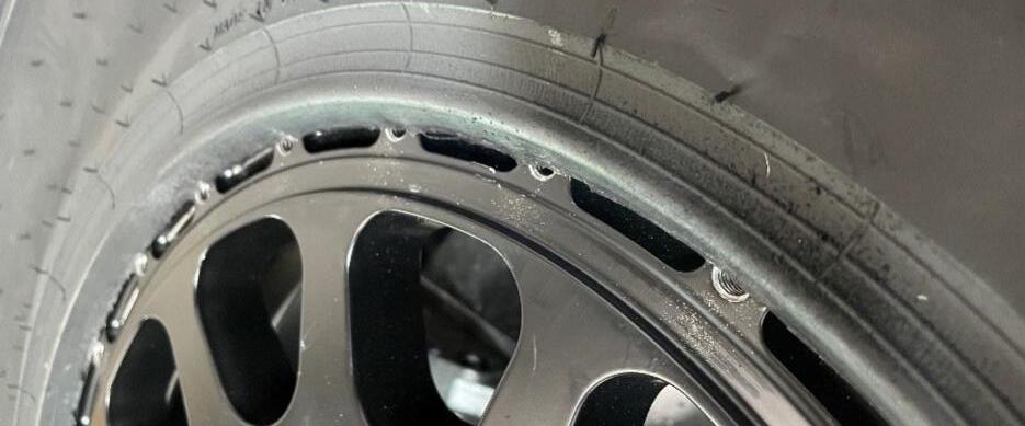
FIG 2: RING FAILURE DUE TO LOOSENING BOLTS WHILE ON VEHICLE
BEADLOCK WHEEL ASSEMBLY PROCEDURE
This section will provide a general overview on the assembly procedure for a beadlock wheel.
General precautions to follow when working with beadlock wheels are:
1. Tools and equipment
a. Tire mounting machine or a 5-gallon bucket to hold the wheel (Recommended)
b. Tire mounting lubricant (Required)
c. A set of tire levers/spoons (Recommended)
d. Ratcheting driver and inch socket set (Required)
e. Cordless drill with socket adaptor (Recommended)
f. Calibrated torque wrench (Required)
g. Tire valve installer (Required)
h. Anti-seize compound (Permatex ® 80078 or Loctite ® LB 8150 or comparable) (Recommended)
i. Air compressor with preferred 3/4in supply line for sufficient air volume (Required)
j. Tire inflator with lock-on chuck and minimum 3ft extension hose (Required)
k. Tire safety cage (Required)
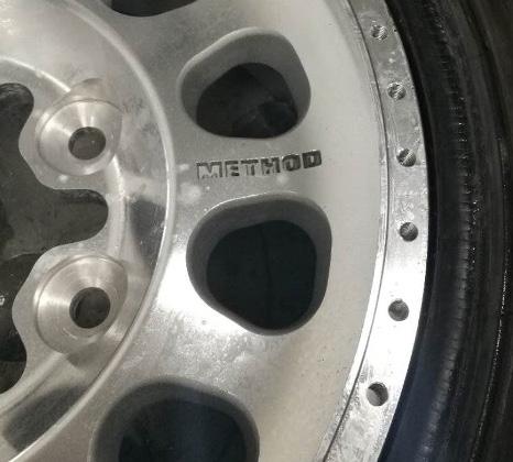
2. Inspect each wheel and tire to make sure they do not have any defects.
3. By hand test the supplied clamp bolts in a few of the beadlock flange tapped holes to confirm the correct bolt kit was in the box and threads are tapped correctly.
a. GMZ UTV wheels use M8x1.25 20mm long Class 10.9 bolts.
b. 14 inch Method wheels use 1/4-20 0.875in long Grade 8 bolts
c. 14 inch Method wheels using a spacer kit use 1/4-20 1.0in long Grade 8 bolts
d. 15 inch Method wheels with or without spacer kit use 5/16-18 1.0in long
Grade 8 bolts
e. 17 and 20 inch Method wheels with or without spacer kit use 5/16-18 1.25in long
Grade 8 bolts
f. 17in Method wheels style MR108 and later use 3/8-16 1.25in bolts.
BEADLOCK INSTALL GUIDE
4. Confirm the tire and wheel are correct size to be used together, i.e. a 17in tire to be installed on a 17in wheel.
5. Using the Beadlock Gauge kit, part number MH-BLGKIT, gauge each tire intended to be installed to make sure it will work with intended wheel.
6. Check 3 different locations on each bead, there will be variation around the bead and from one bead to another. It is possible for one bead to work and the other to not.
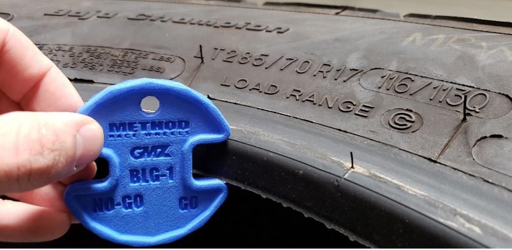
a. BLG-1 is used for MR4XX and GZ8XX UTV wheels.
b. BLG-2 is used for 15in and 17in MR101, MR103, MR105, MR106, MR201, and MR202 wheels except MR103 17x9.
c. BLG-3 is used for 17in MR103 17x9 and 20in MR105 wheels.
7. The beadlock gauges have two slots a “GO” and “NO-GO”.
8. If a tire bead fits in the “NO GO” slot it is too small to be used with that wheel, the ring will not clamp the bead sufficiently.
9. If the tire bead is too large to fit in the “NO GO” slot but does fit in the “GO” slot the tire is safe to use with that wheel and should not require a spacer kit.
10. If the tire bead does not fit in the “NO GO” or the “GO” slots then that tire will require a spacer kit to be used with that wheel.
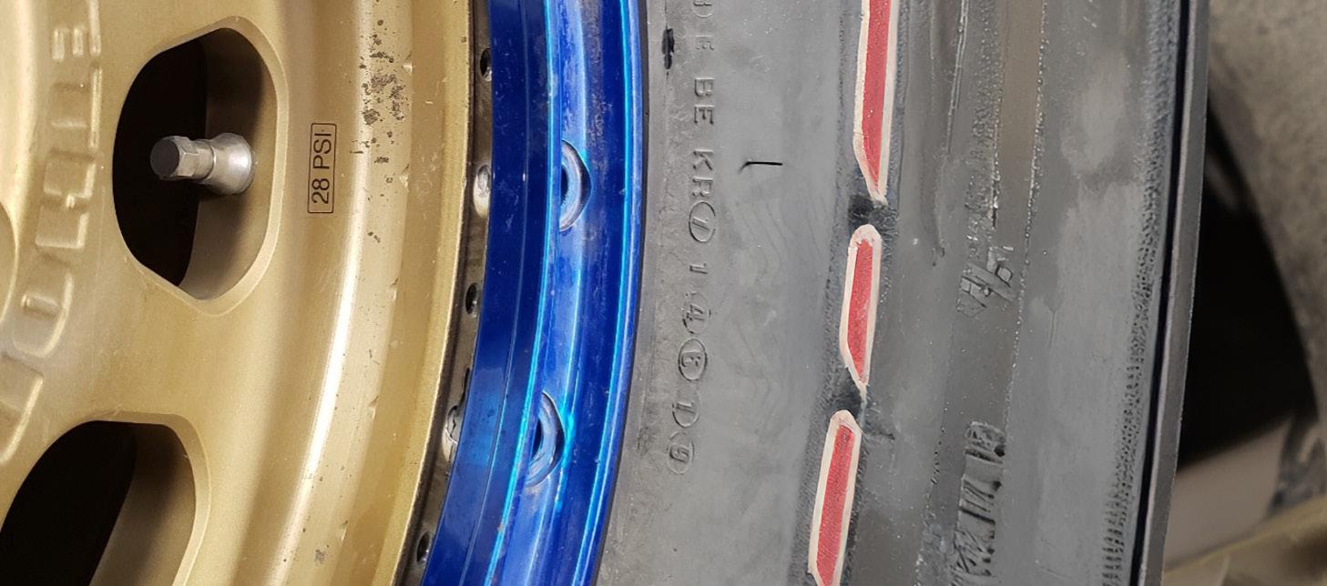
11. Make sure there is no extra rubber flash at the base of the tire’s bead. This can either stop you from properly installing the tire on the wheel or lead to sealing issues. Trim any excess with a razor knife being careful not to cut the actual bead.
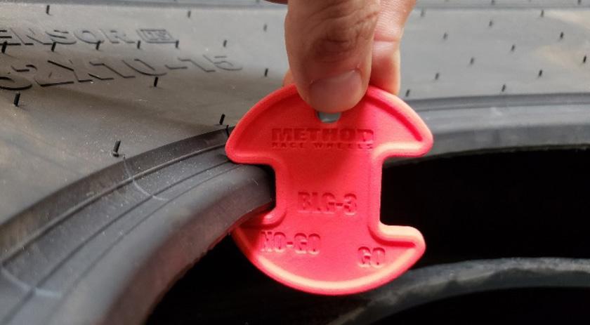
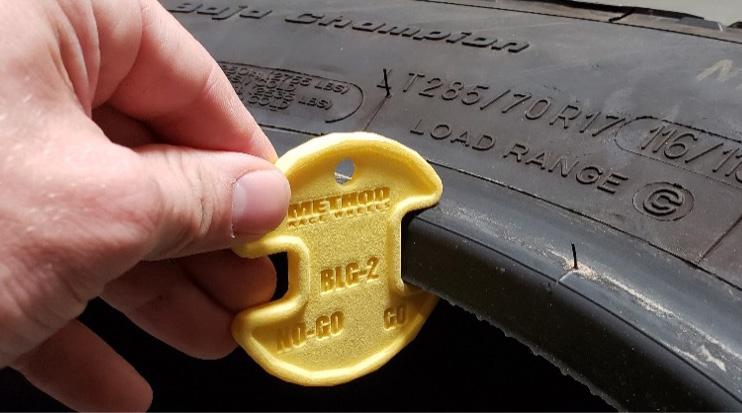
FIG 3: BEADLOCK GAUGE NO-GO CONDITION CHECK, BEAD IS TOO SMALL FOR USE WITH WHEEL.
FIG 4: BEADLOCK GAUGE GO CONDITION CHECK, NO SPACER KIT REQUIRED.
BEADLOCK INSTALL GUIDE
12. Install the supplied valve stem in the wheel’s valve hole.
a. MR401-R +46 and MR103 HD wheels utilize an NPT threaded valve which requires a specific installation procedure, link provided below and QR code is inside boxes of these wheels which displays instructions when scanned.
b. http://qrco.de/bbCysk
13. Place the wheel face side up in the mounting machine clamps, on top a top of a 5-gallon bucket, or on the floor.
14. Lubricate the inner tire bead to help it slide over wheel surfaces easier.
15. Place the tire on the wheel using body weight to force the inner bead over the beadlock flange. The tire should pass over the flange with some force, but a set of levers/spoons may help.
16. With the inner bead now on the opposite side of the beadlock flange rest the outer bead on the flange and align it so it appears concentric to the tapped holes. Make sure the bead is sitting below the surface with the tapped holes.
17. Place the beadlock ring on the outer tire bead and align the through holes to the tapped holes in the wheel, there will be a gap between the ring and the wheel at this point.
18. Place the included washers in the counter bores of the beadlock ring.
FIG 5: BEADLOCK GAUGE NO-GO AND GO CONDITION FAIL, SPACER KIT WOULD BE REQUIRED. DO NOT INSTALL LT TIRES ON UTV WHEELS.
BEADLOCK

19. Apply anti-seize to the entire length of each bolt’s threads.
20. By hand install each of the bolts with 5 complete turns to ensure cross threading does not occur.
21. You can now choose to either use a ratchet and socket or a cordless drill with a socket adaptor to further thread the bolts in the wheel using a star pattern until the head begins to contact the washer which will be sitting against the ring.
a. If using a cordless drill which is much faster make sure to set the clutch to about 1/3 the available range, normally “3”. This ensures you do not damage threads. Do not use a drill with the clutch set to the drill setting.
b. Do not use an impact driver.
22. Once the bolt heads are contacting the washers and ring you will need to switch to using a torque wrench.
FIG 6: MOUNTING ORIENTATION
FIG 7: OUTER TIRE BEAD CORRECTLY ON BEADLOCK FLANGE, SAFE FOR INSTALLATION.
BEADLOCK INSTALL GUIDE
23. Recommended final torque values for each bolt size are:
a. M8x1.25 with anti-seize is 9 lb-ft (12.2 N-m), dry is 14 lb-ft (18.9 N-m)
b. 1/4-20 with anti-seize is 8 lb-ft (10.9 N-m), dry is 12 lb-ft (16.3 N-m)
c. 5/16-18 with anti-seize is 20 lb-ft (27.1 N-m), dry is 24 lb-ft (32.5 N-m)
d. 3/8-16 with anti-seize 28 lb-ft (37.9 N-m) , dry is 35 lb-ft (47.5 N-m).
24. Torque should be applied to bolts in a star or cross pattern to make sure the ring is compressing the tire bead equally around the entire circumference. Not doing so will lead to damaging the ring, breaking bolts, or misalignment of the tire on the wheel.
25. It is best to increase torque in stages for all bolts. Start by taking all bolts to half of recommended, then 80% of recommended, and then final torque.
a. For 1/4-20 bolts with anti-seize this is 4 lb-ft (5.4 N-m), then 6 lb-ft (8.1 N-m), and finally to 8 lb-ft (10.9 N-m).
b. For 5/16-18 bolts with anti-seize this is 10 lb-ft (13.6 N-m), then 16 lb-ft (21.7 N-m), and finally to 20 lb-ft (27.1 N-m).
c. For 3/8-16 bolts with anti-seize this is 14 lb -ft (19 N-m), then 22.4 lb-ft (30.4 N-m), and finally to 28 lb-ft (37.9N-m).
FIG 8: TIRE BEAD INCORRECTLY ON FLANGE, NOT SAFE FOR INSTALLATION.
BEADLOCK INSTALL GUIDE
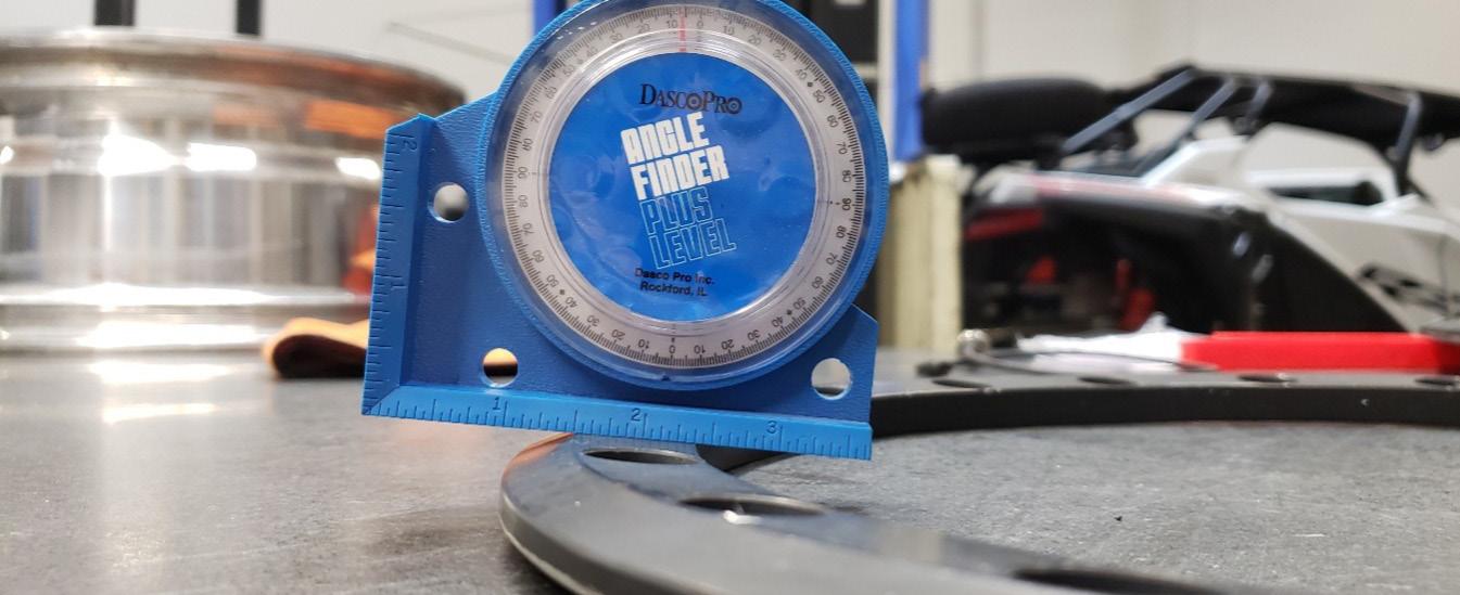
26. The ring should be in contact with the wheel once you complete the final torque step
27. SAFETY CRITICAL, if the ring is not in contact with the wheel it is not safe to use, the bolts will loosen.
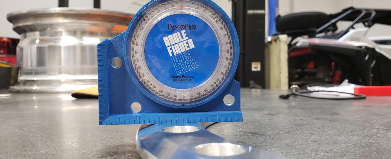
28. If the gap between the ring and wheel is 1/16in or less (0.0625in or 1.6mm) it is likely possible to close the gap by increasing final torque values by 1-2 lb-ft on 14 inch wheels and 2-4 lb-ft on 15/17/20 inch wheels.
29. If the gap does not close after trying the increased final torque values the wheel will need to be disassembled and a beadlock spacer kit used, repeat assembly steps up until this point.
30. Beadlock spacer kits go between the ring and the wheel to increase the flange gap.
31. Place the tire and wheel assembly in the tire safety cage and attach the inflator’s lock on chuck to the valve in the wheel.
32. Move to a safe location at least 3 feet away. Stand on the non-beadlock side of the wheel you are trying to seat, do not stand on the side that has the beadlock ring and bolts.
33. Begin inflating to seat the inner tire bead.
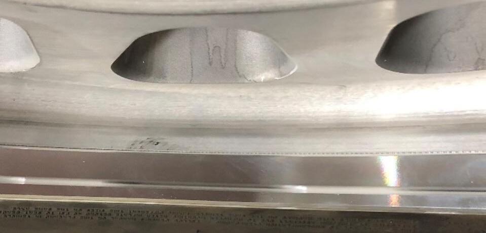
FIG 9: NO GAP BETWEEN RING AND WHEEL, SAFE.
BEADLOCK INSTALL GUIDE
34. Inner bead seating pressure will vary depending on wheel and tire combination but should occur at a maximum of 50 psi (3.4 bar).
35. Once the tire is seated remove the tire from the safety cage and recheck the torque on each bolt.
36. A good practice is to use a marker to make a reference dot or line on each bolt. This helps to provide a visual if any bolts have loosened once installed on vehicle.
37. The tire and wheel assembly can now be balanced if desired and installed on vehicle.
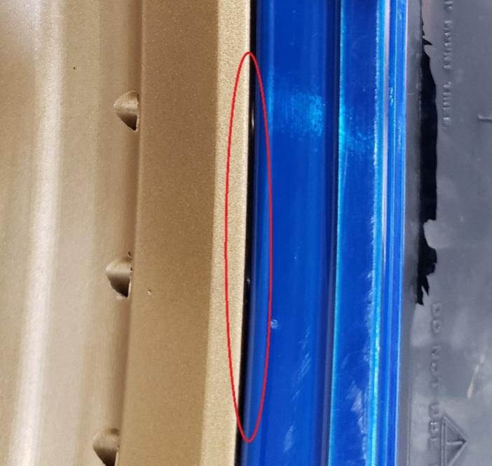
FIG 10: GAP BETWEEN RING AND WHEEL, NOT SAFE.
OUTER TIRE BEAD IS PINCHED IN BETWEEN THE OUTER LIP OF WHEEL AND BEADLOCK RING. ORANGE = BEADLOCK RING SPACER (IF APPLICABLE)
INNER TIRE BEAD GOES HERE
BEADLOCK WHEEL DISASSEMBLY
This section will provide a general overview on the disassembly procedure for a beadlock wheel.
1. SAFETY CRITICAL, never loosen or remove beadlock clamp bolts with pressure in the tire. Serious injury or product damage can occur.
2. Remove valve core from the valve stem to release all pressure from tire.
3. Use tire machine bead breaker to break inner tire bead from the inner beadseat.
4. It is now safe to remove the beadlock clamp bolts.
5. With all clamp bolts removed and the beadlock ring set aside the tire can now be fully removed from the wheel over the beadlock flange. A set of tire levers or spoons may be helpful.
6. Once everything is apart it is critical to inspect the wheel, bolts, washers, and beadlock ring for any damage or wear.
7. SAFETY CRITICAL, inspect the wheel for any bends or cracks. Do not reuse wheels with bends or cracks and do not attempt to repair bent wheels.
BEADLOCK INSTALL GUIDE
8. Inspect the tapped holes in the wheel for damaged threads or debris in the holes.
a. Some wheels have two sets of tapped holes. If any damage is found in tapped holes the wheel can still be used by utilizing the other set of holes for reassembly.
9. It is strongly recommended to use a new set of bolts and washers each time a wheel is assembled with a different tire.
a. Beadlock hardware kit part numbers are:
i. For GMZ wheels use BH-H2020M
ii. For 14 inch Method wheels without beadlock spacers use BH-H20875
iii. For 14 inch Method wheels with beadlock spacers use BH-H20100
iv. For 15 inch Method wheels use BH-H24100
v. For 17 inch MR101, MR103, MR105, and MR106 wheels use BH-H24125
vi. For 17in MR108 wheels use BH-H24125-38
vii. For 20 inch wheels use BH-H36125
10. If you must reuse bolts make sure to inspect them for corrosion, damaged threads, or structural damage. Do not use if any issues are present, doing so can result in injury or product damage.
11. Place the beadlock ring either on the wheel’s beadlock flange or a known flat surface in its installation orientation to confirm it is still flat.
12. It is possible to permanently deform the beadlock ring into a cone shape if a beadlock spacer kit was not used when it should have been, or torque exceeded recommendations.
13. SAFETY CRITICAL, a ring that has been permanently deformed has reduced strength and reduced ability to clamp a replacement tire as intended. It must be replaced with a new ring for safe operation.
14. Upon completing inspection of all parts and replacing any observed to have problems follow the assembly instructions detailed previously in this document.
If there are any questions regarding any information detailed in this document please contact us. Email: info@customwheelhouse.com
FIG 12: PERMANENTLY DEFORMED BEADLOCK RING, THIS IS NOT SAFE TO USE ANYMORE.
FIG 13: NEW BEADLOCK RING, ZERO DEFORMATION.