Chapter 2: Sequence
To succeed in your course, you will be expected to have a working understanding of flowcharts and pseudocode. You will need to be able to use them to explain the logic of your solutions to given tasks. Both methods are used throughout this book. syllabus check
Problem solving and design: use flowcharts and pseudocode.
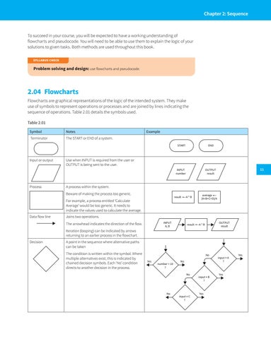
2.04 Flowcharts Flowcharts are graphical representations of the logic of the intended system. They make use of symbols to represent operations or processes and are joined by lines indicating the sequence of operations. Table 2.01 details the symbols used. Table 2.01 Symbol
Notes
Terminator
The START or END of a system.
Input or output
Process
Example END
INPUT number
OUTPUT result
Use when INPUT is required from the user or OUTPUT is being sent to the user. 11
A process within the system. Beware of making the process too generic.
result
For example, a process entitled ‘Calculate Average’ would be too generic. It needs to indicate the values used to calculate the average. Data flow line
START
A*B
average (A+B+C+D)/4
Joins two operations. INPUT A, B
The arrowhead indicates the direction of the flow.
result
OUTPUT result
A*B
Iteration (looping) can be indicated by arrows returning to an earlier process in the flowchart. Decision
A point in the sequence where alternative paths can be taken The condition is written within the symbol. Where multiple alternatives exist, this is indicated by chained decision symbols. Each ‘No’ condition directs to another decision in the process.
No Yes
number > 10 ?
No
No
No
input = C ?
input = B ?
Yes
input = A ?
Yes
Yes