


Notes:
- Grab your 1 tee shirt in lobby at break or lunch
- Please make sure to fill out NDA paperwork quick and pass to RH end of rows
8:00 Introductions (Recognitions)
8:15 Safety
9:00 Main Pump - Hydraulics Theory and Application
10:00 Bridge King Hydraulic System
11:30 Cylinders (Trailer & Chute)
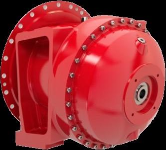
11:45 Gearbox
12:00 Lunch
1:00 Electrical 2:00 Air System
3:00 Parts Information 4:00 Remarks
6:00 Dinner
Groups 1-6
7:00 am - Breakfast
7:30 am - Opening Remarks
8:00 am - Stations at Event Center
Lanyard
Colors - Brown - Dark Blue - Silver
- Red - Purple - Light Green
-Station 1: BridgeKing Cyl Maintenance
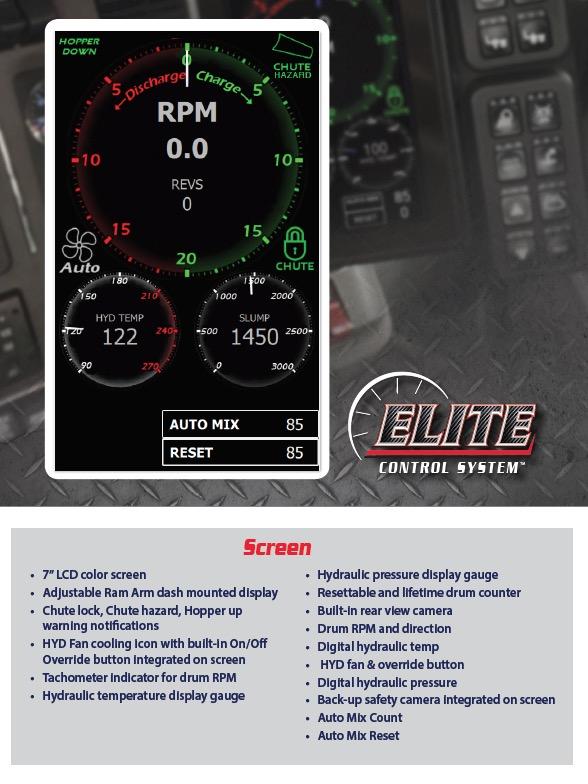
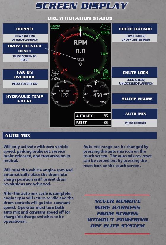
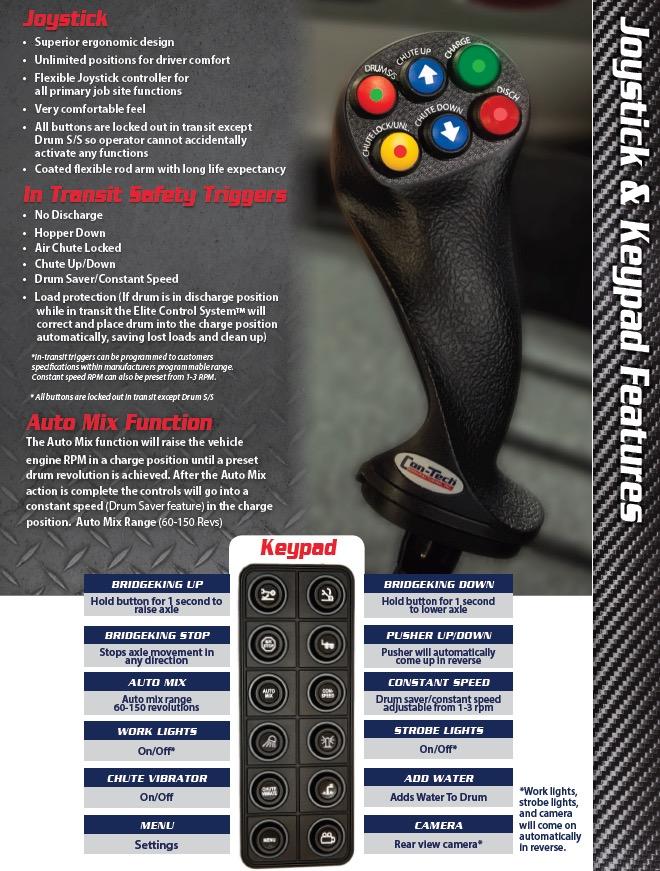
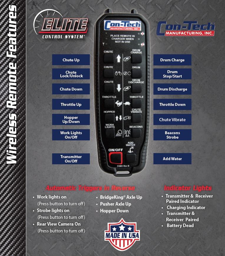
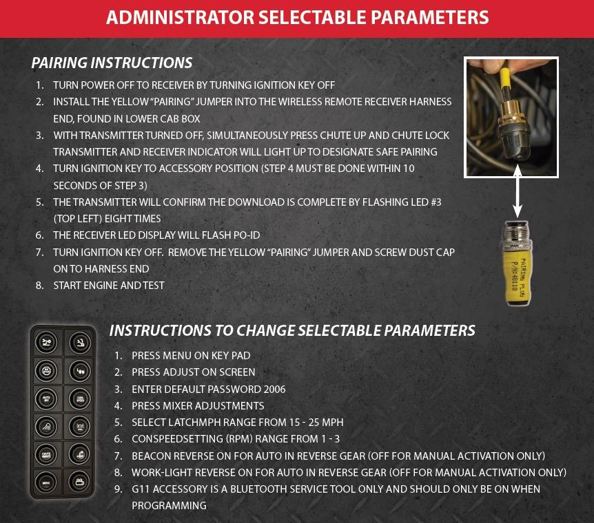
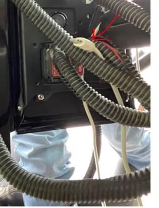
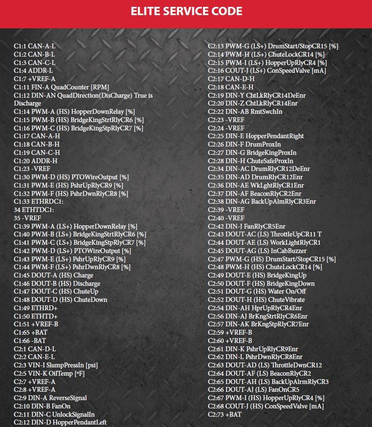
-Station 2: Elite Control System
-Station 3: Pumps & Controls
-Station 4: MAC Values
-Station 5: Standard Controls & Electrical Harness
-Station 6: Website Tutorial
11:00 am - Lunch
12:00 pm - Load Buses for Factory
12:30 pm - Stations/Tour
-Tour Group 1
-Tour Group 2
-Station 7: Drum Measuring & Roller Adjustment
-Station 8: BridgeKing Hydraulics
-Station 9: BridgeKing Axle and Pusher Axles
4:00 pm - Departure
Groups 7-12
7:00 am - Breakfast
7:30 am - Opening Remarks
8:00 am - Load Buses for Factory
8:30 am – Factory Stations/Tour
Lanyard Colors - White - Orange - Light Blue - Yellow - Black - Dark Green
-Tour Group 1
-Tour Group 2
-Station 7: Drum Measuring & Roller Adjustment
-Station 8: BridgeKing Hydraulics
-Station 9: BK Axle and Pusher Maintenance
11:30 am - Load Buses
12:00 pm - Lunch
1:00 pm
- Stations at Event Center
-Station 1: BridgeKing Cyl Maintenance -Station 2: Elite Controls Station
-Station 3: Pumps & Controls -Station 4: MAC Values
-Station 5: Standard Controls & Electrical Harness
-Station 6: Website Tutorial
4:00 pm - Departure

Hwy 56 South
“To each there comes in their lifetime a special moment when they are figuratively tapped on the shoulder and offered the chance to do a very special thing, unique to them and fitted to their talents. What a tragedy if that moment finds them unprepared or unqualified for that which could have been their finest hour.”
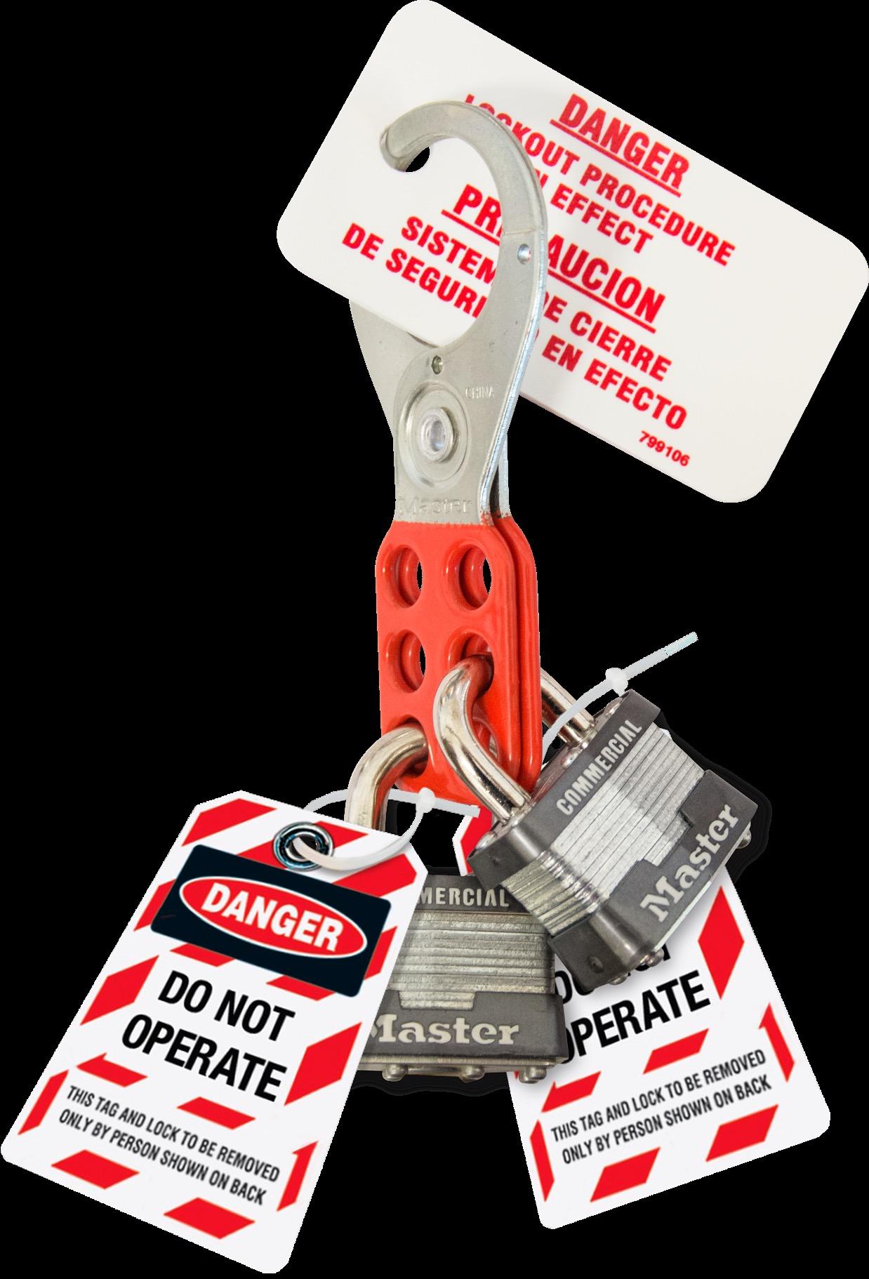
OSHA 1910.147 (SAE 2957)
This standard covers the servicing and maintenance of machines and equipment in which the unexpected energization or start up of the machines or equipment, or release of stored energy, could harm employees
- Battery Shut Off/Disconnect
- Wheel Chocks
- Drum Roller Lock Out Wedges
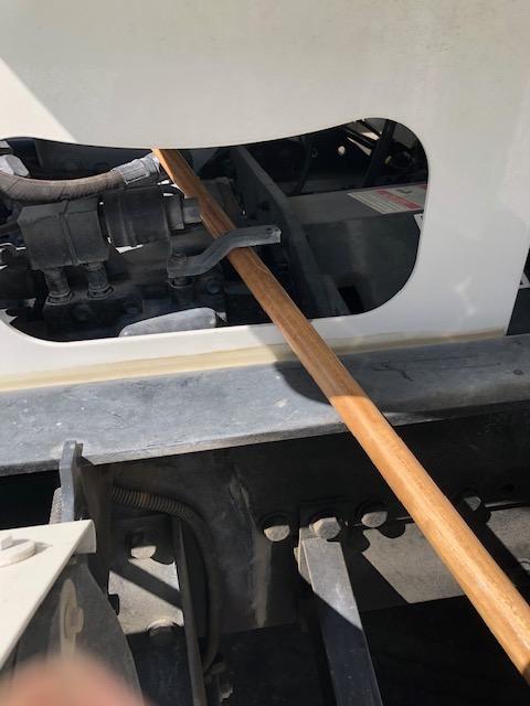
- Hydraulic Pump Lever Arm Lockout Device
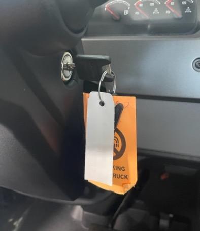
- Truck Keys in Pocket or Lock Box
Terminology
- Potential Energy: Stored energy
- Kinetic Energy: Energy in motion
- A good, consistent lockout program minimizes the risk of when potential energy turns into kinetic energy

DAY BEFORE YESTERDAY

TRUCK: 2022 OUT OF SERVICE VIOLATIONS PERCENTAGES (3 DAYS-59,000+ INSPECTIONS)


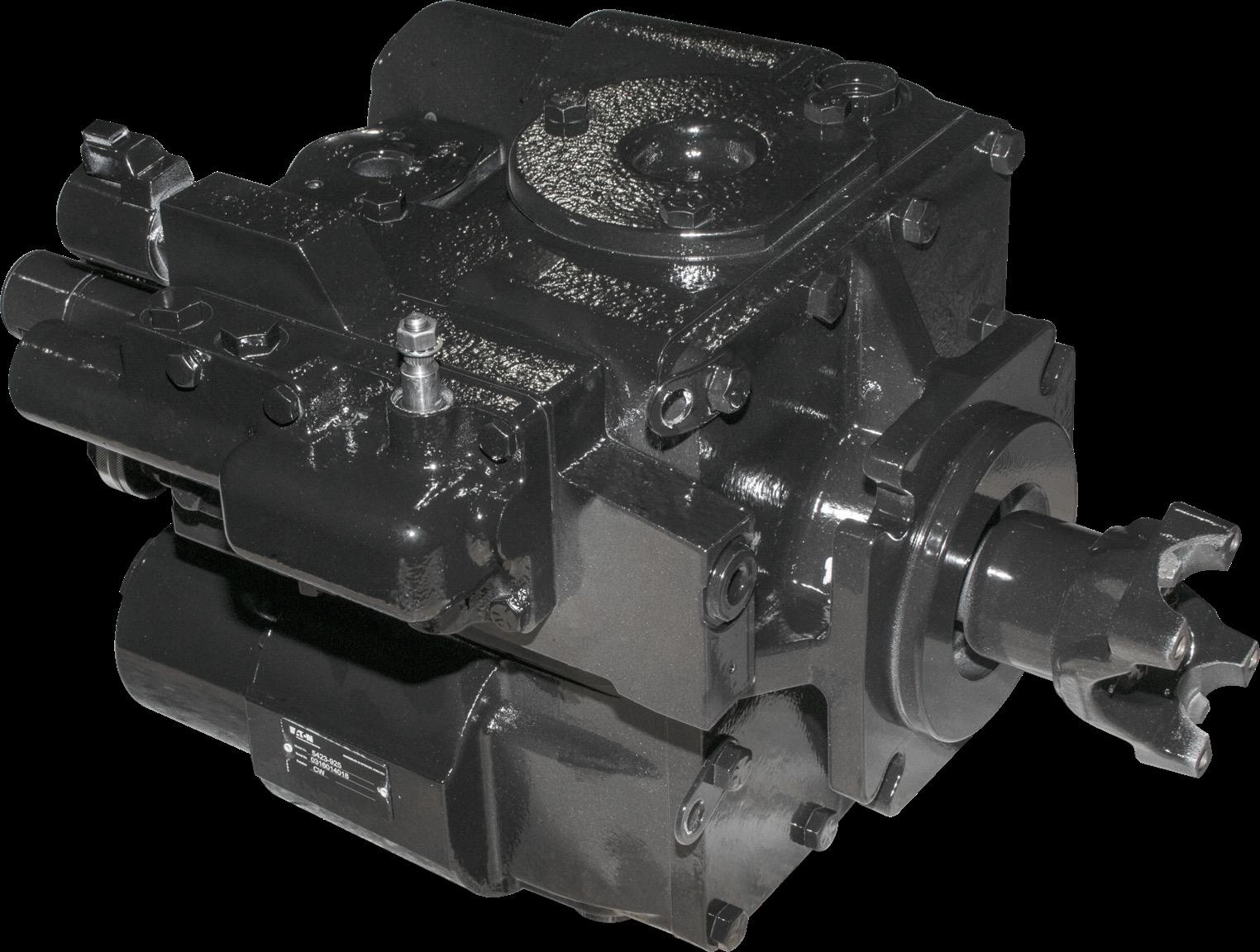
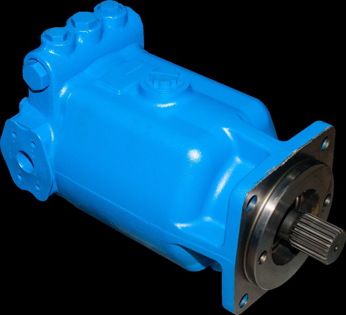
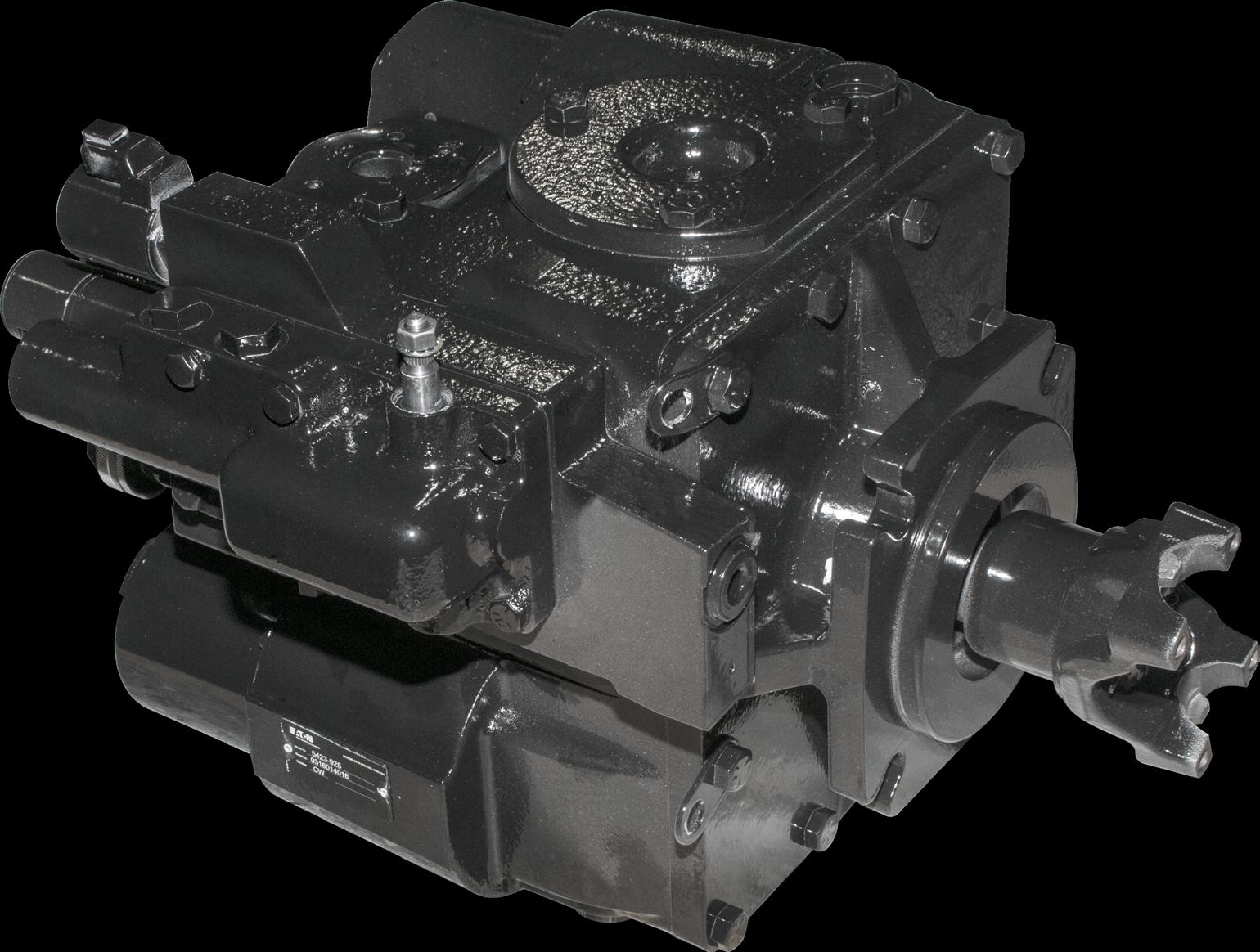
- Eaton/Danfoss 54 Series Variable Displacement Pump
- Eaton/Danfoss 54 Series Fixed Displacement Motor
- Hydraulic Fluid
- Hydraulic Filters
- Hydraulic Oil Reservoir
- Oil Base Stock
The base oil (ie: petroleum or mineral) that is the starting point for hydraulic fluid and other oils
- Additive Packages
Additive packages are supplemental “kits” that are added to base stocks to achieve desirable characteristics
Anti-Wear (AW): Usually Zinc
Emulsifiers: Water dissipation
VII: Viscosity Index Improver
- Fluid Recommendations from Eaton
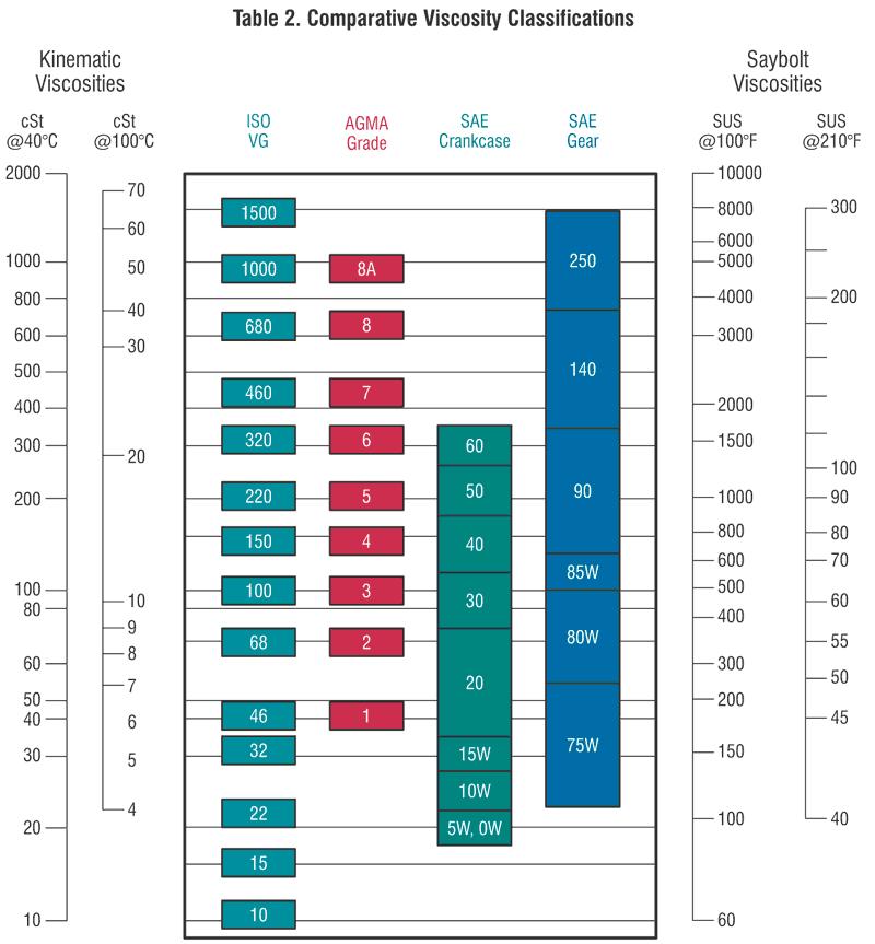
- ISO = International Standards Organization
- Average ambient below 80’F = ISO68 Fluid
- SUS @ 210’F = 55-60
- Viscosity Index (VI) = 100-120
- Pour Point = -25’F Avg
- Average ambient above 80’F = ISO100 Fluid
- SUS @ 210’F = 60-70
- Viscosity Index (VI) = 100-120
- Pour Point = -5’F – +10’F
Avg Temp>80’F
Avg Temp<80’F
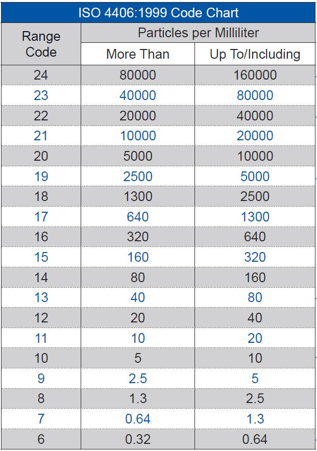
- ISO Cleanliness Coding System
- Eaton Target ISO Code: 18/15/13
- 4m/6m/14m
- 18 = 1300 - 2500 ppMl 4 micron & larger
- 15 = 160 - 320 ppMl 6 micron & larger
- 13 = 40 – 80 ppMl 14 micron & larger
- Example of difference of 1 step up the scale
- 19/16/14
- 19 = 2500 – 5000 ppMl 4 micron & larger
- 16 = 320 – 640 ppMl 6 micron & larger
- 14 = 80 – 160 ppMl 14 micron & larger
* 1m=.00004”
4 100,000th’s
* Grain Salt=100m .004”
* Hair = 70m .0028”
* See > 40m .0016”
* Blood Cell=25m .001”
- Recommended Service Intervals
- After initial 100 hours
- Every ~ 1000 hours there after
- Keep Cool
- Check fan cooler operation often
- Operator should be discharging at 1200-1400 engine RPMs & control drum speed with controls
- Use the Correct Filters
- Suction (Spin On)Filter Rating: B10=2 (catches 50% of x<10m 1st pass)
- Could go to lower filter rating but would be in bypass MUCH longer!!
- Also @ 5m rating, strips the additive package from oil base stock
- High Pressure Filter Rating: B10=200 (catches 99.5% of x<10m 1st pass)
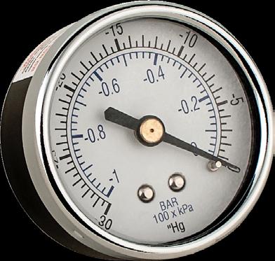
- Watch filter vacuum gauge
- X<10” at start up, 2”<x<5” after oil is warm
- If x>10”, filter is in bypass
Note: Tighten filter till contact with head and then ½ turn
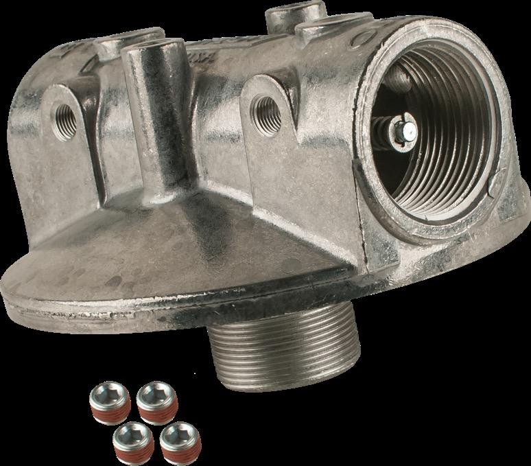
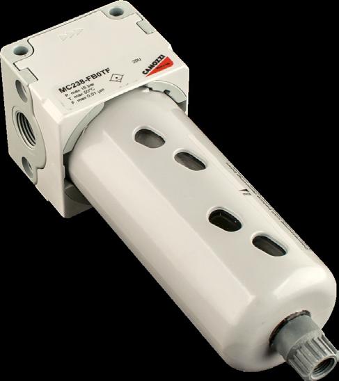
Screws on top of hydraulic reservoir and hooks to shop air. Creates vacuum inside tank which allows hydraulic repairs to be made with minimal oil loss.
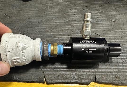
• Times to use?
• Replacing Parker or Chute Pump
• Maintenance intervals don’t line up
• For you that only change oil every OTHER filter change
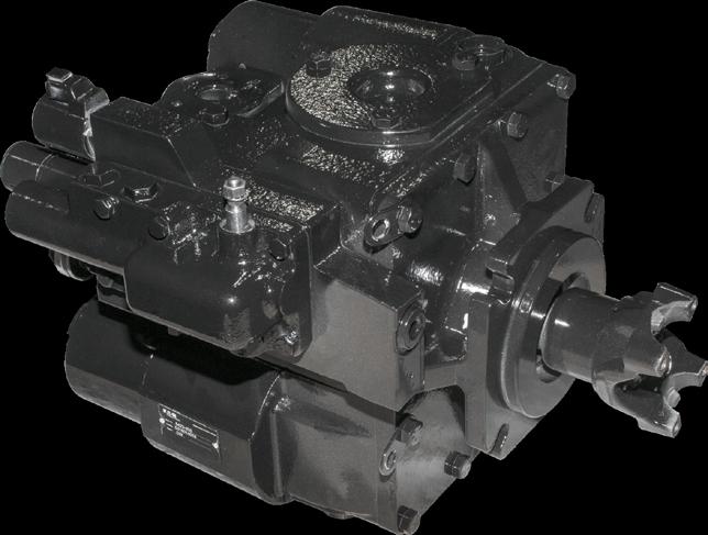
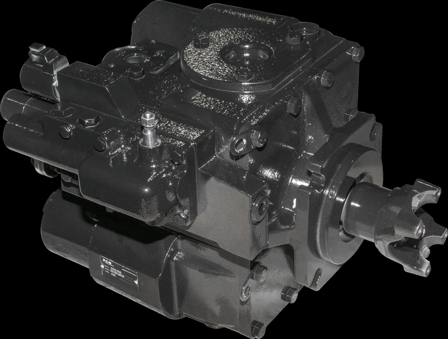
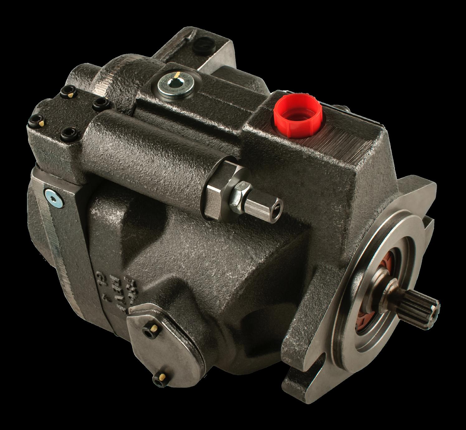
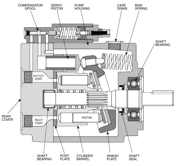
- Eaton (now Danfoss) 54 Series Pump
- Variable Displacement Rotary Piston Pump
- Commonly referred to as “Closed Loop”
- Closed loop means that fluid travels in the high pressure circuits in a “circular” motion between the charge & discharge loops (hi/low side)
- 8 pistons rotating on swash plate create displacement (0-5.4 cu in)
- Swash plate angle determines displacement
- Controller (on side of pump) determines swash plate angle via pressure applied to servo cans
- Type of controllers (Manual, RE, EP)
- Right hand (clockwise)rotation – REAR of cab UNLESS Cummins X-12
- Left hand (counter clockwise) – Front REAR Cummins X-

- Charge pump – Gerotor Style (real heart of system)
- Generates control pressure to shift servo cans
- Old=220 psi, New=280psi
- Charge Pressure Relief Valve controls PSI
- Makes up for leakage (5% of displacement) in rotating groups (high press circuit leakage)
- Leakage referred to as “case drain”
- Originates in motor (top), flows to bottom of pump & out top of pump thru cooler back reservoir
- Purposes: Cool & clean
- Without adequate charge pump pressure, cannot shift servo cans, create displacement and turn drum
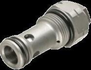
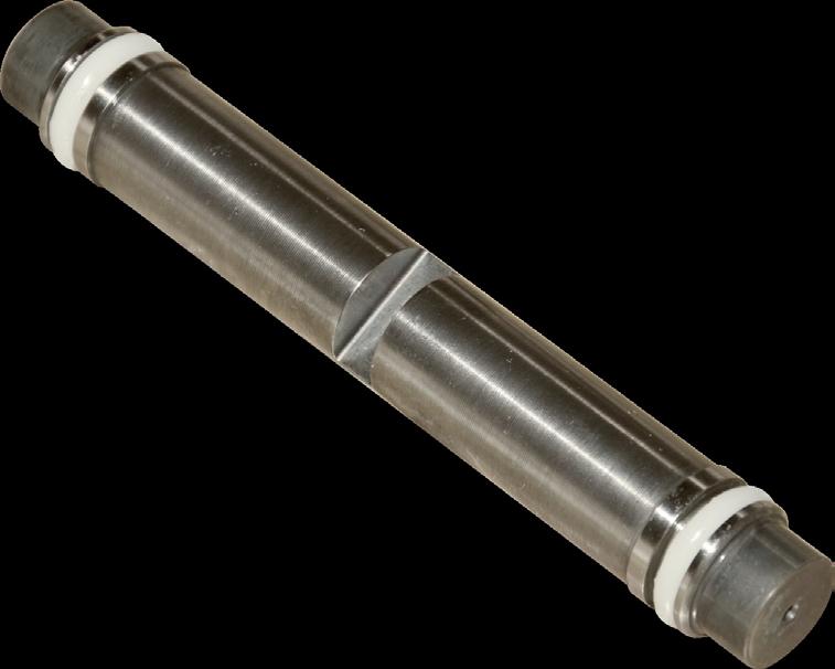
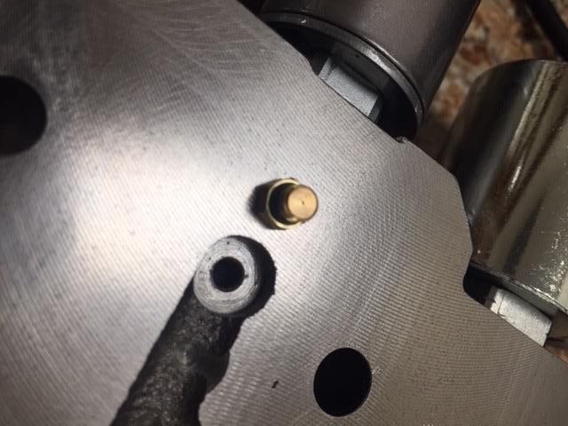
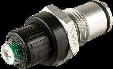
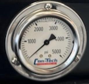
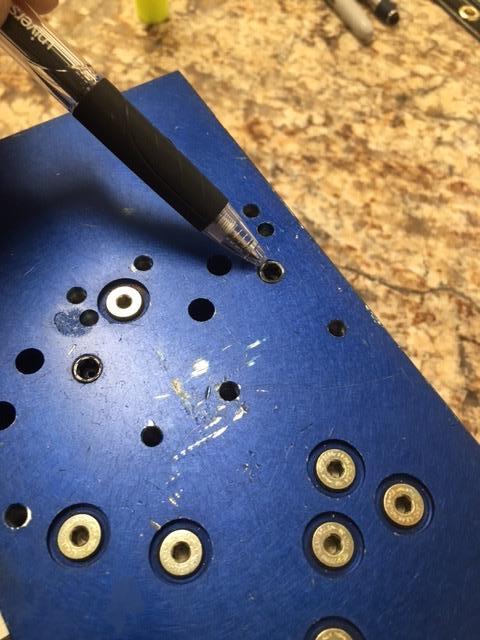
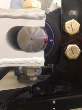
- Charge pump pressure test procedure:
- With engine turned off, install #500 gauge
- Start truck engine and run at idle
- Pump in neutral: x > 280 psi (Con-Tech)
- Pump in full stroke: x > 220 psi (Con-Tech)
-
Notes
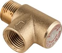
• When testing charge pressure with gauge, charge pressure reading should NOT vary with engine RPM
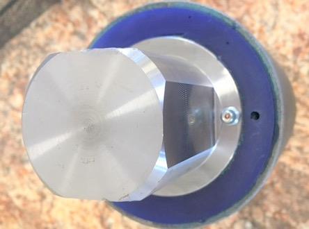
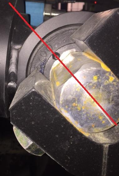
• If reading LOW, remove and inspect valve
• DO NOT REMOVE WITH OUTER ¾” CAP, ONLY REMOVE WITH 1.25” WRENCH/SOCKET ON INNER HEX HEAD
• Inspect oring
• Hold valve up to the light and make sure you CANNOT see daylight between the cage and poppet holes. This is a CLOSED valve so if you can see daylight, something has it stuck open
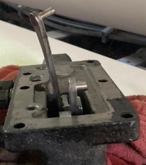
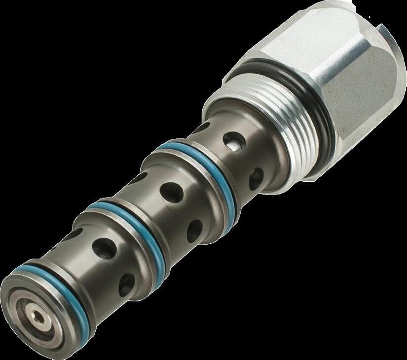
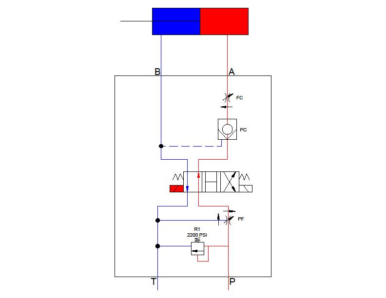
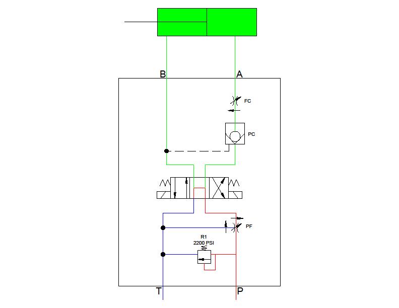
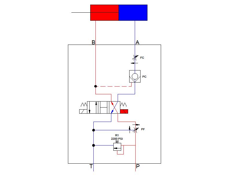
Flow From Pump To Motor and Motor Back To Pump (ie: High Pressure “A” & “B” circuits)
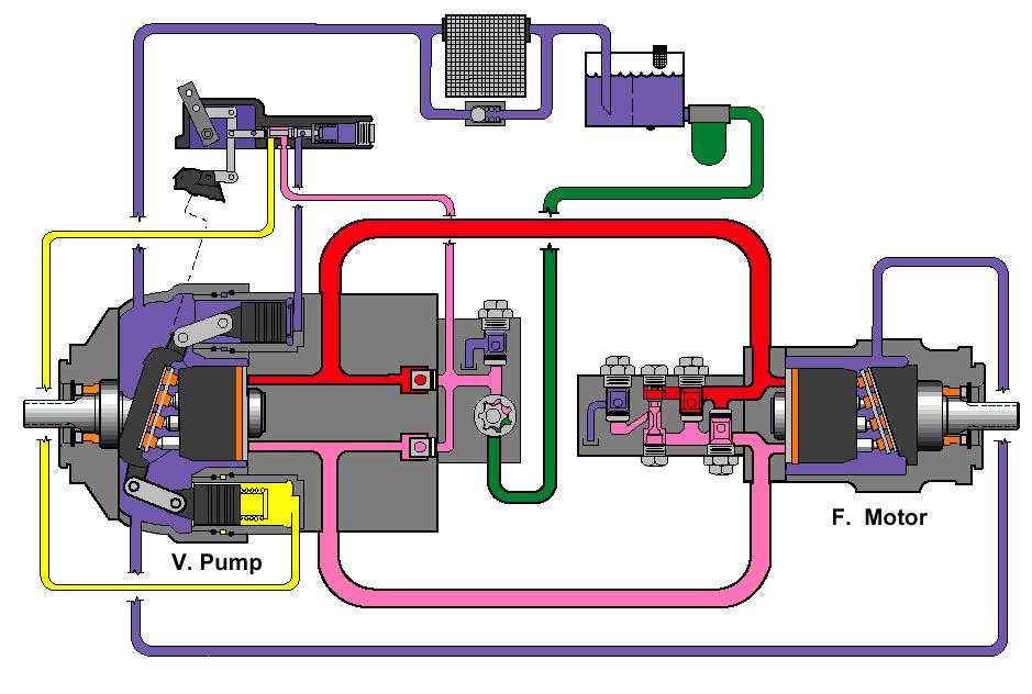
- Go to live animation
- Drum Start-Stop is normally CLOSED cartridge
- Take 12V power to open and stop drum
- Connects pathway between charge -discharge servo cans and “neutrals” swashplate in pump
- NOTE: If valve sticks OPEN, drum will not turn no matter what
- Remove valve and plug ports if suspect
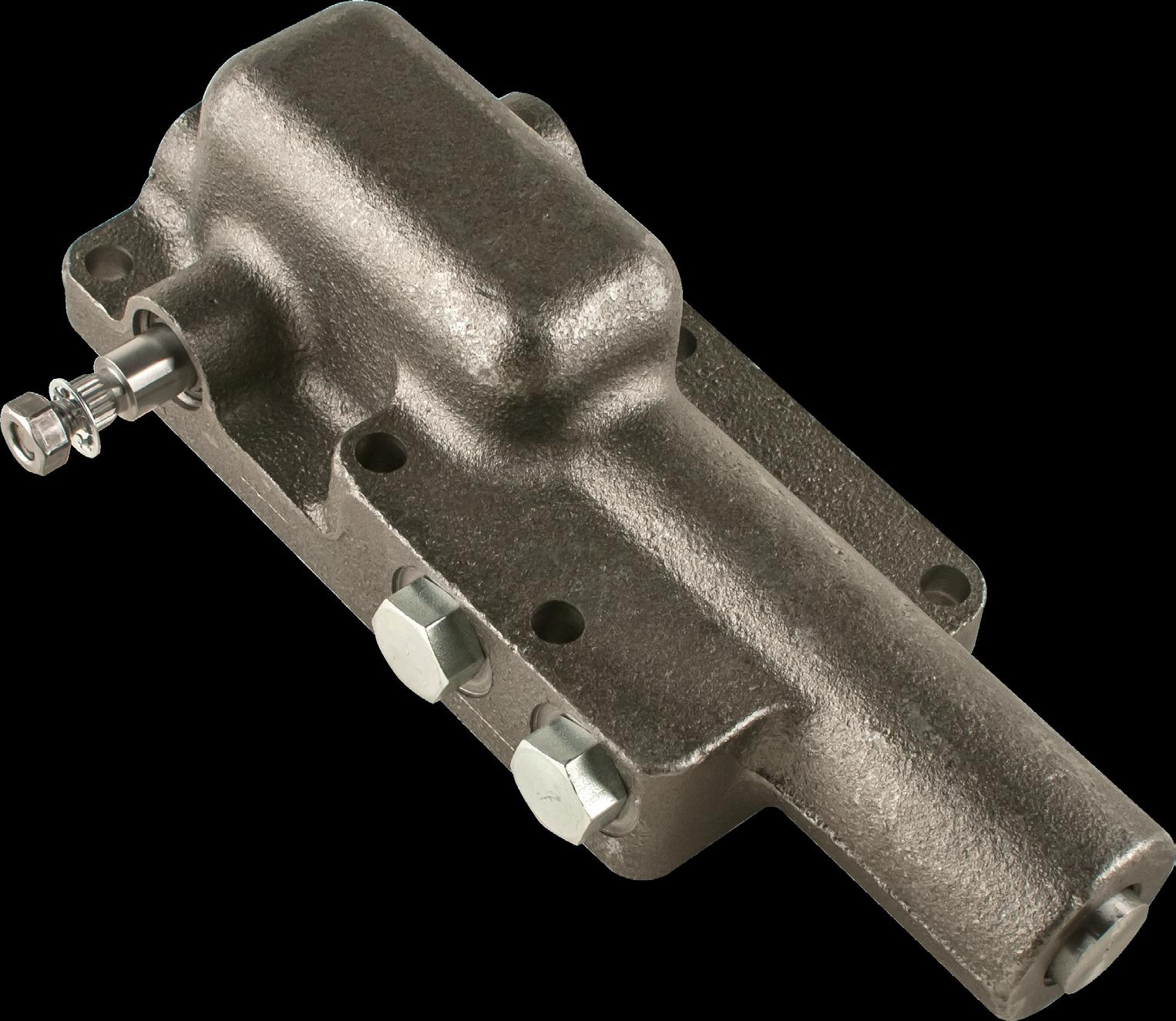
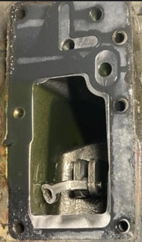
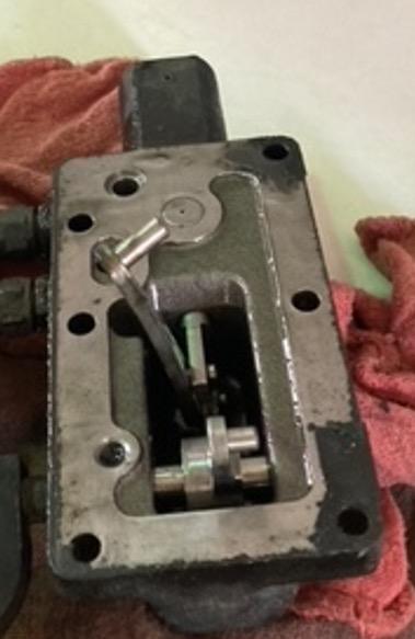
Charge/Discharge Cart/Coil Manual Override Valve
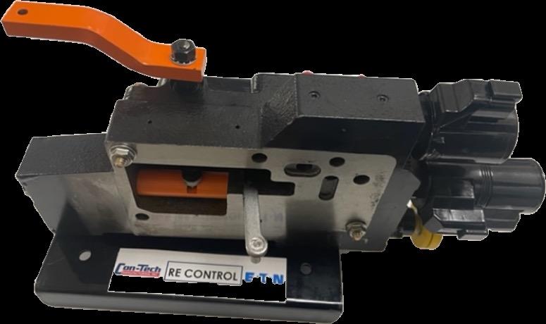
- RE Controller
- Utilizes 12V coils to shift pump
- Charge/Discharge coils control pressure to either side of piston which shifts and just “drags” outer control valve
- Start-Stop valve opens to equalize pressures between servo cans (allows swash plate to neutral)
- NOTE: If drum fades to stop – O-rings worn on control piston in controller
- NOTE: Set drum to charge and watch arm on outer control valve. Does it move (on it’s own) back to the neutral position & the drum slows to a stop???
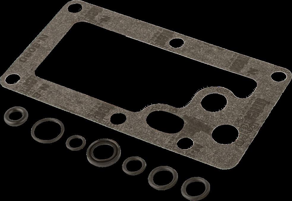
- O-Rings #725049 (x2)
- RE Gaskets #740005 (x2)
- Spool (if req’d) #725037
- Note: While in there, clean screen!!
Charge-Discharge
Emergency
Start-Stop
Cavity Plug #740044
- Controller Inlet Screen/Orifice
- Symptom: Slow controller motion from charge to discharge
- Causes
- Partially Open Override Valve
- Plugged Orifice Screen
- Low Charge Pressure
1. Loosen inner “jam” knob CCW out till touches outer knob
2. Turn outer knob CCW (out) until it stops
3. Control pump/drum with arm
Notes:
• On wireless remote units, the drum STOP function is activated when the ignition key is turned ON
• A shorted out coil will fault the Omnex receiver upon key ON

• Easy way to tell is that the charge-discharge and chute up-down will still work from cab box switches
Added Slide
• The shuttle valve in the motor is the last component that controls the direction of the drum.
• The valve controls the flow of hydraulic fluid around the rotating group (pistons) in the motor
• How to diagnose
• Is the arm on control valve on the pump moving normally but the drum will not respond
• Remove shuttle and check for contamination
Customer had full charge and only partial discharge…………..hmmmmmm
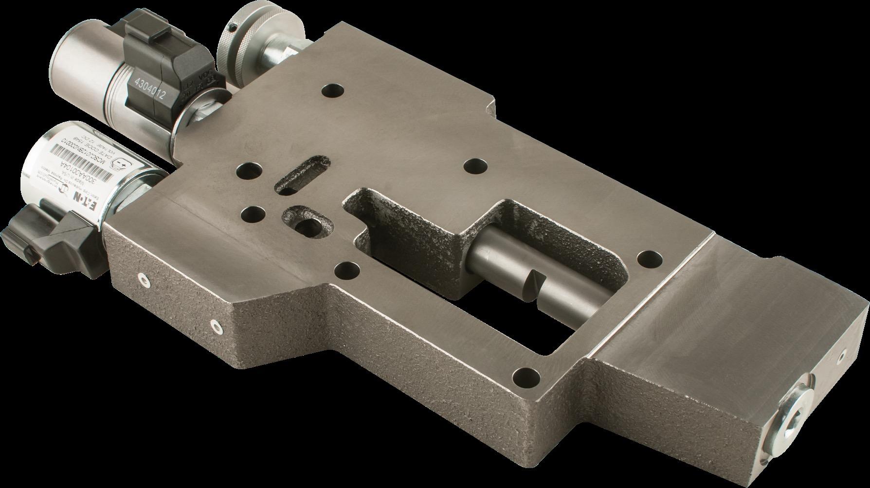
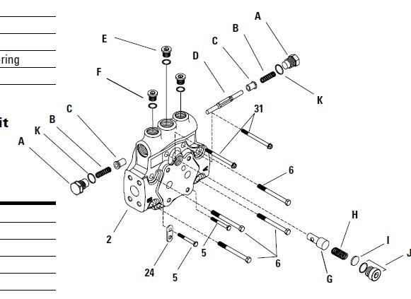
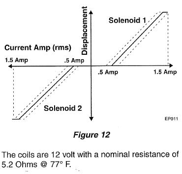
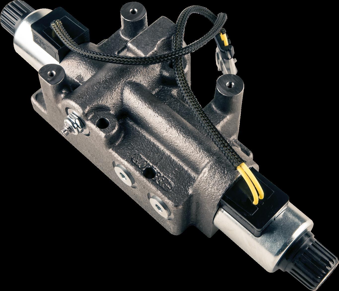
- EP (Electronic Proportional) Controller
- Uses .5 - 1.5 Amps to control (balance) spool position inside controller
- Utilizes “maestro” controller to manage spool position based on setting input from toggle switch (by varying current to coils)
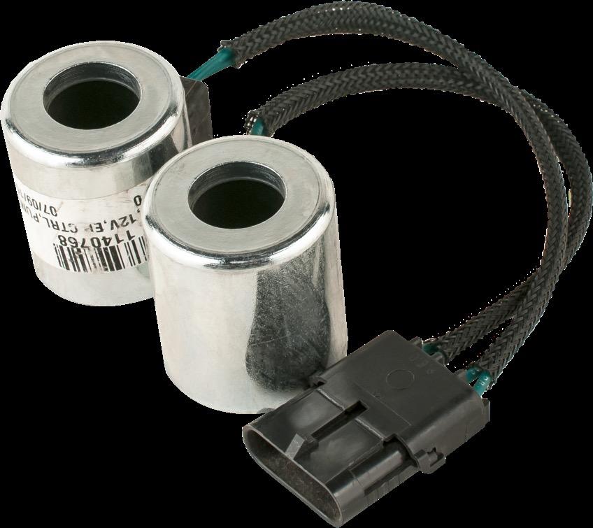
- Coil Ohms (resistance) = ~6.5 -7.0
- Initial diagnosis steps anytime drum control issues are present
- Check resistance in coils
- Remove coils and clean coil and cartridge stem/tube
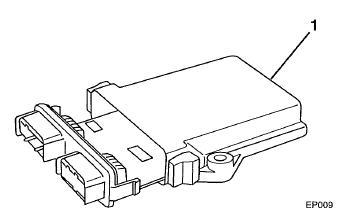
“Maestro” Control Module
12V+ Inputs from front and rear discharge switches
- Charge
- Discharge
Check with test light or multi-meter/power probe while depressing switches
Trunnion Cover Oring #725000
Servo Can Socket #740100

Servo Can O-rings
Sm #725000
Lg #725004
If drum creeps when stop activated, adjust servo can in/out
Note: ALWAYS mark servo cans prior to adjusting or removing!
Shaft Seal Driver #799616
Input Shaft Seal Kit #725015
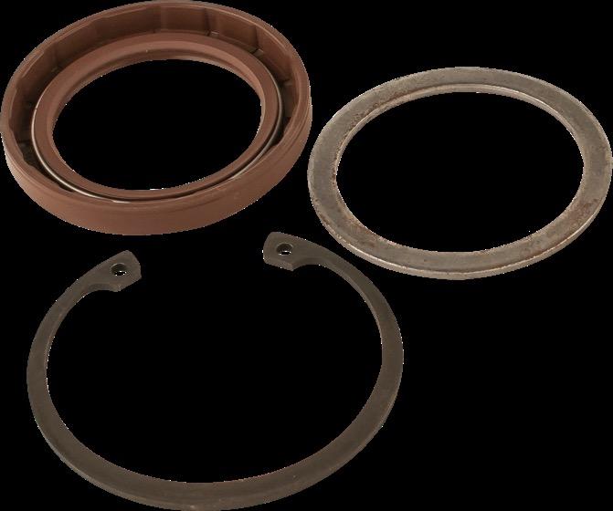
Torque=320 ft/lbs
Then to next slot for cotter pin
Note: There is NO backstop for seal!!
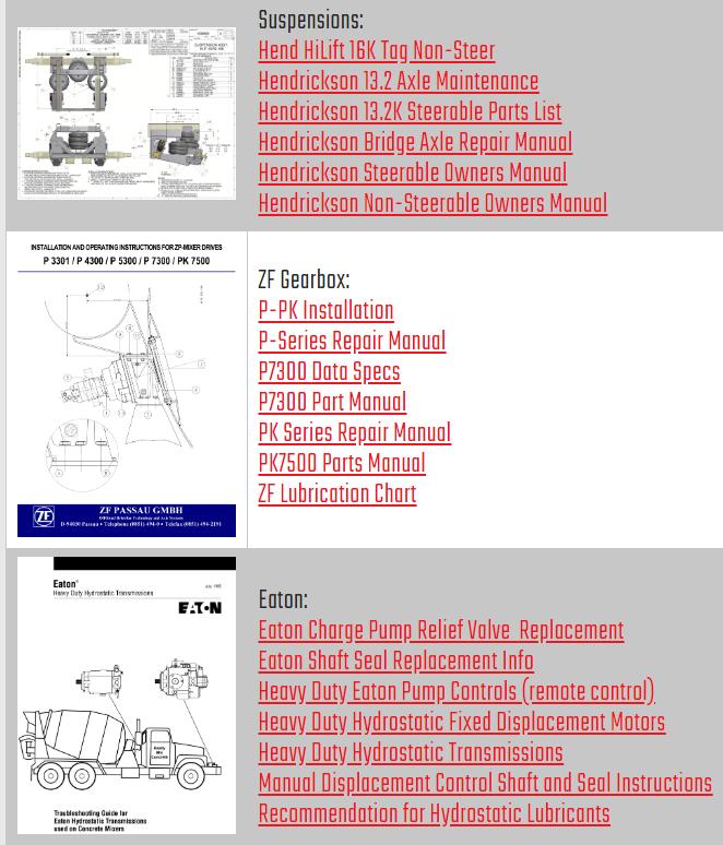
- ZF was the primary US supplier for gearboxes
- Lubricant 85w90 gear lubricant that meets the GL5 specification (4.2 gal)
- Recommended lubricant change intervals
- After initial 100 hours, every 1000 hours thereafter
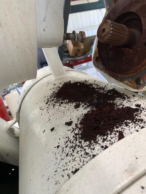
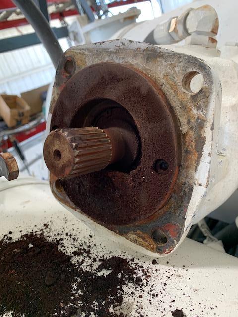
- If output seal found leaking:
- Check dipstick for correct fluid level
- Raise output seal (umbrella) and clean behind it with quick clean. Re-inspect after 20-30 hours of operation
- Do NOT recommend synthetic gear lube (cost, service intervals, leakage, internal damage)
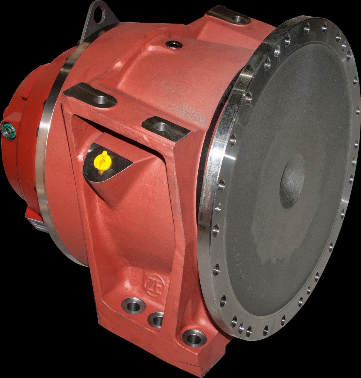
• Manufactured in Italy
• Most mixer manufacturers have moved to PMP due to product availability issues w/ ZF
• Gearlube:85W90 or 85w140
• Oil Capacity: 14L (3.7 gal)
• Gear Ratio: 127.6:1
• Interchangeable w/ZF
Sight glass locate on driver side
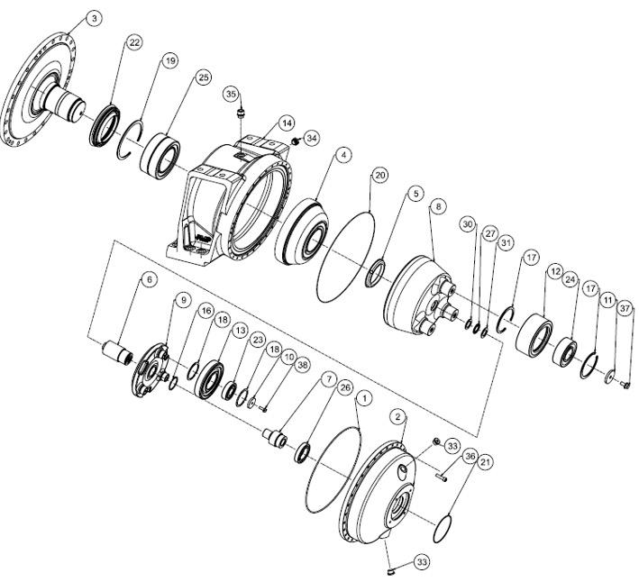
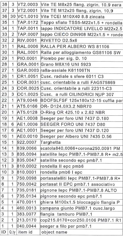
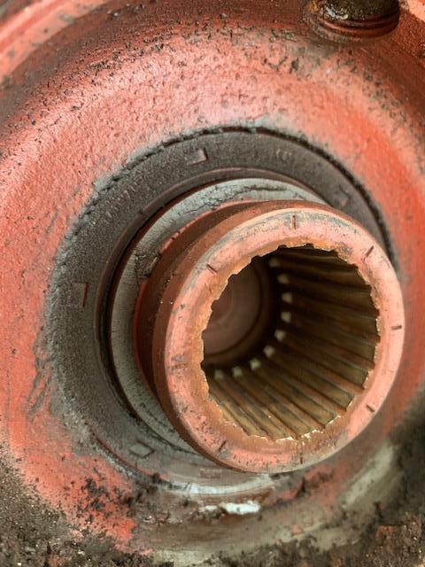
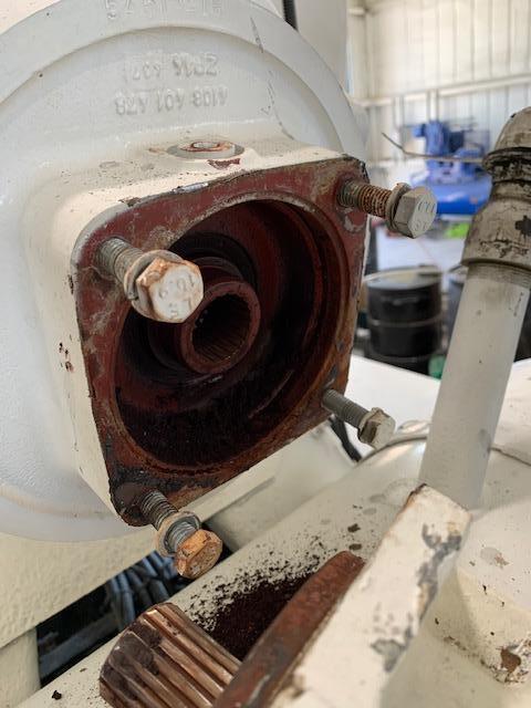
ZF-PMP GEARBOX NOTE: DO NOT INSTALL INPUT SHAFT SEAL IN GEARBOX!!
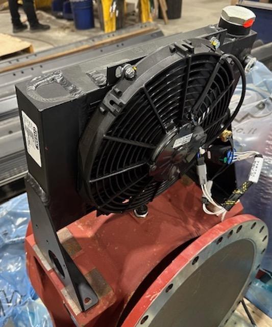
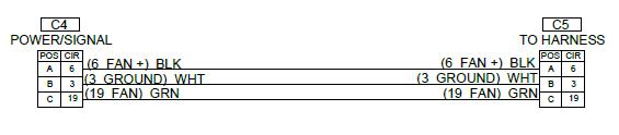
- The fan cooler is an integral part of the hydraulic system.
- Con-Tech uses an ASA fan cooler
- Cooler flow TOTAL capacity = 35 Gpm
- Hydraulic fluid flow at WOT = 13.5 Gpm (case drain only)
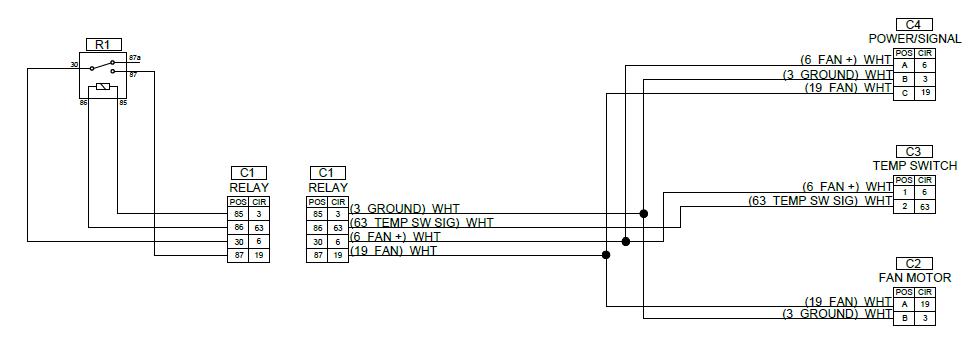
- Utilizes a single temp switch set @ 157’F
- 30 Amp relay controls on-off power
- Simple installation and retro fit as only need power & ground
- Has 3rd wire for “fan on” output (to turn on a light in cab or elsewhere
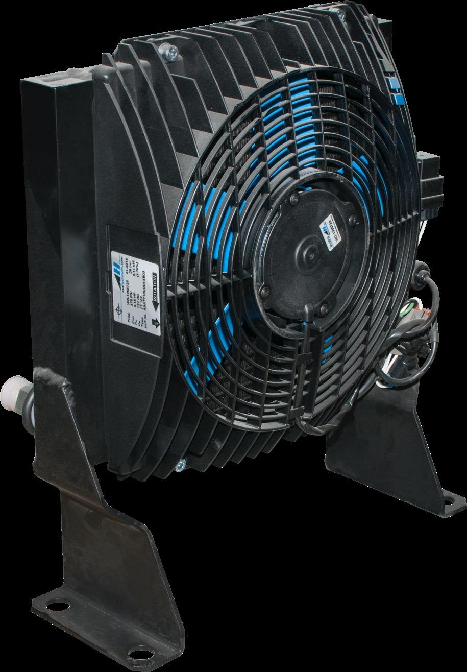
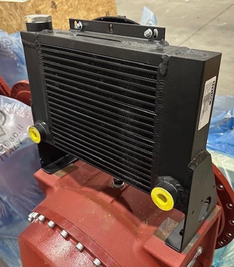
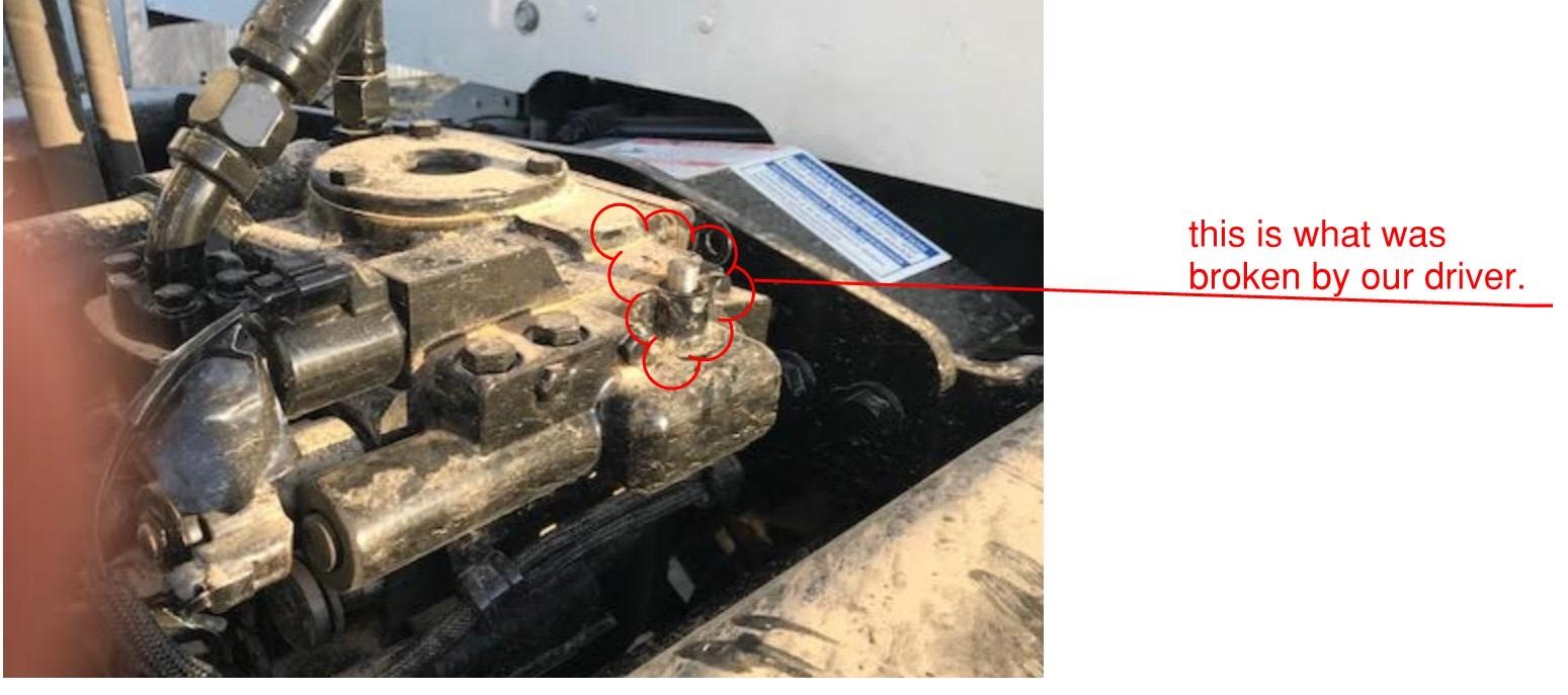
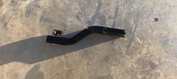
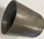
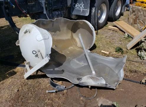
Improved leg design Less Bends
Thicker Material
Fan Cooler Assembly #740500
Note: Has 50 psi bypass to keep case pressures low ie: cold weather/thick oil
Fan/Motor Assembly #740502
Fan Temp Switch #740501
Fan Cooler Power Relay #715065
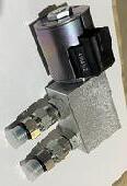
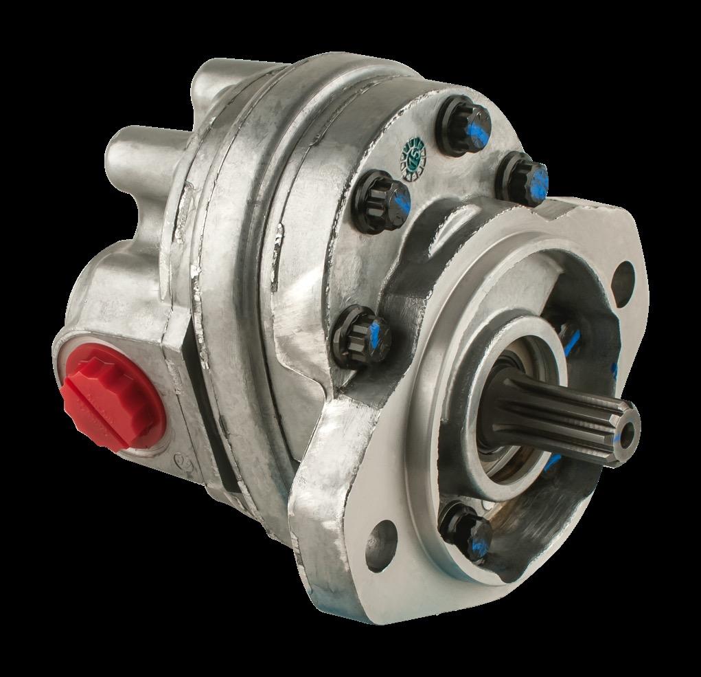
- Parker Pump
- Pressure compensated piston pump (1 cu in)
- Pump is “self adjusting” to comp setting
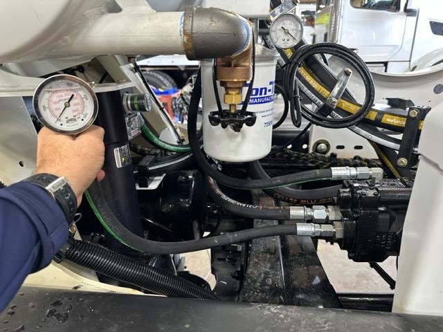
- Testing
- Deadhead pressure hose (that goes to filter) into 5000psi gauge & start truck
- Failure indicators: No pressure or pressure fluctuates up/dn with engine RPM
- Also can check case drain volume. Place case drain line in bucket, at idle should be about ½ gpm (new), 2 ½ GPM on used pump
- If pressure is only slightly off, then adjust using compensator adjustment screw (in= psi increase) to 100 psi above highest setting on placard
- Pressure on gauge should be set to 100 psi over maximum setting on axle psi placard
- Right hand (clockwise)rotation –
REAR of cab UNLESS Cummins X-
12
- Left hand (counter clockwise) –
Front bumper mount OR REAR
Cummins X-

How does it work?
• Compensator “self-regulates” pressure to set pressure
• Bias spring keeps pump at full stroke/pressure till outlet pressure matches comp setting and then destrokes the pump
1. With truck shut off, disconnect -8 pressure hose from high pressure filter
2. Install #5000 gauge
3. Start truck engine
4. At idle, should go immediately to #3000
5. Should NOT vary dependent on engine RPM
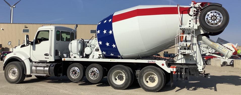
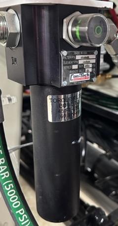
- Bridge King Mixers
- Inspect high pressure filter bypass indicator daily
- By pass indicator trips at 50 psi pressure drop across filter
- The bypass filter indicates pressure DROP & will only read when raising/lowering trailer or raising/lowering chute
- Notes:
- Oil Capacities
- Standard Mixer: 13 gallons + 2 gallons in system
- Bridge Mixers: 18 gallons + 5 gallons in system
- Lefthand Pump Rotation: Front Engine AND Rear Engine Cummins X-12
- Rear (REPTO) mount pumps = Right hand pumps
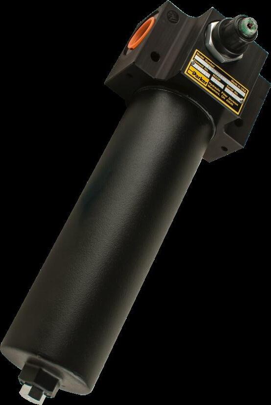
Parker Filter Assy
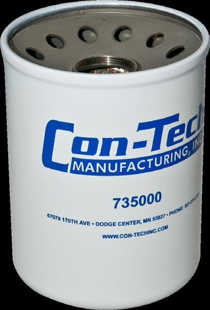
O-Ring #725019
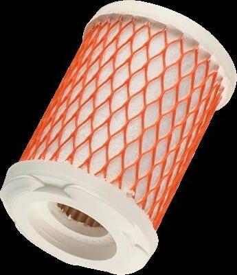
Cartridge #735003
Can Torque 30-35 ft lbs
Drain Torque 15-20 ft lbs
Schroeder Filter
Assembly #735019
Cartridge #735003
By-Pass Ind #760094
Round O-Ring #735021
Square O-Ring #735022
Canister Torque 45 ft lbs
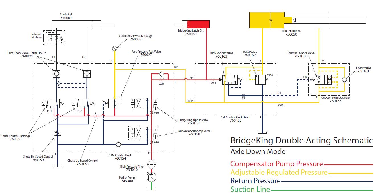
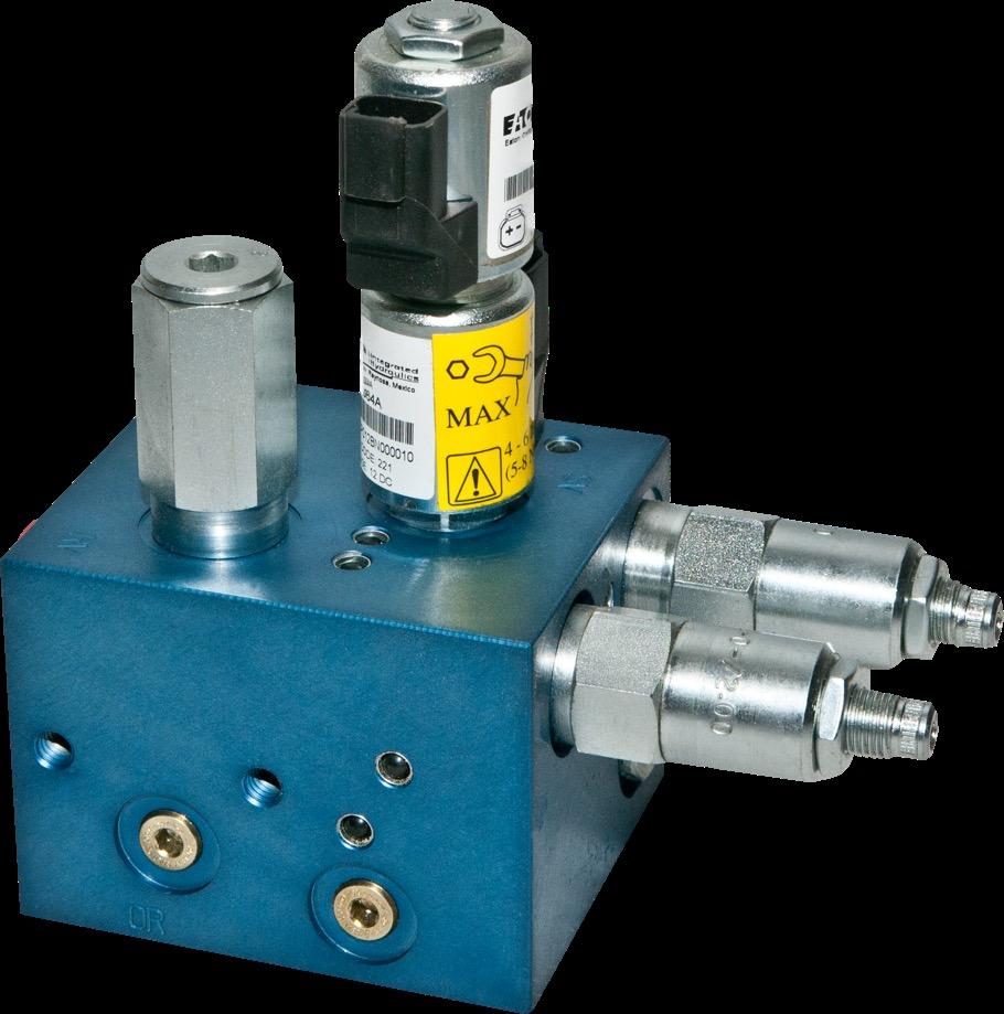
BK Axle
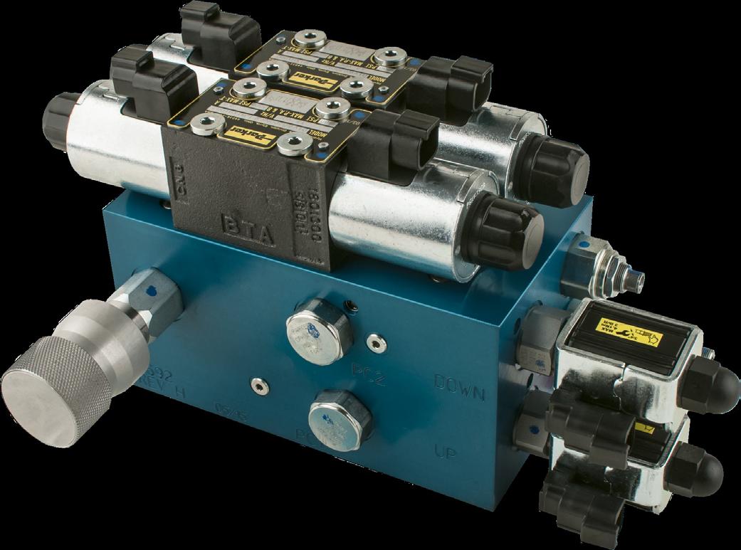
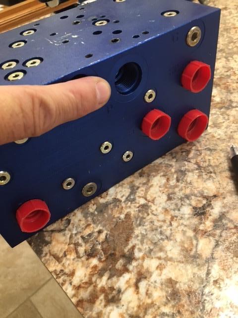
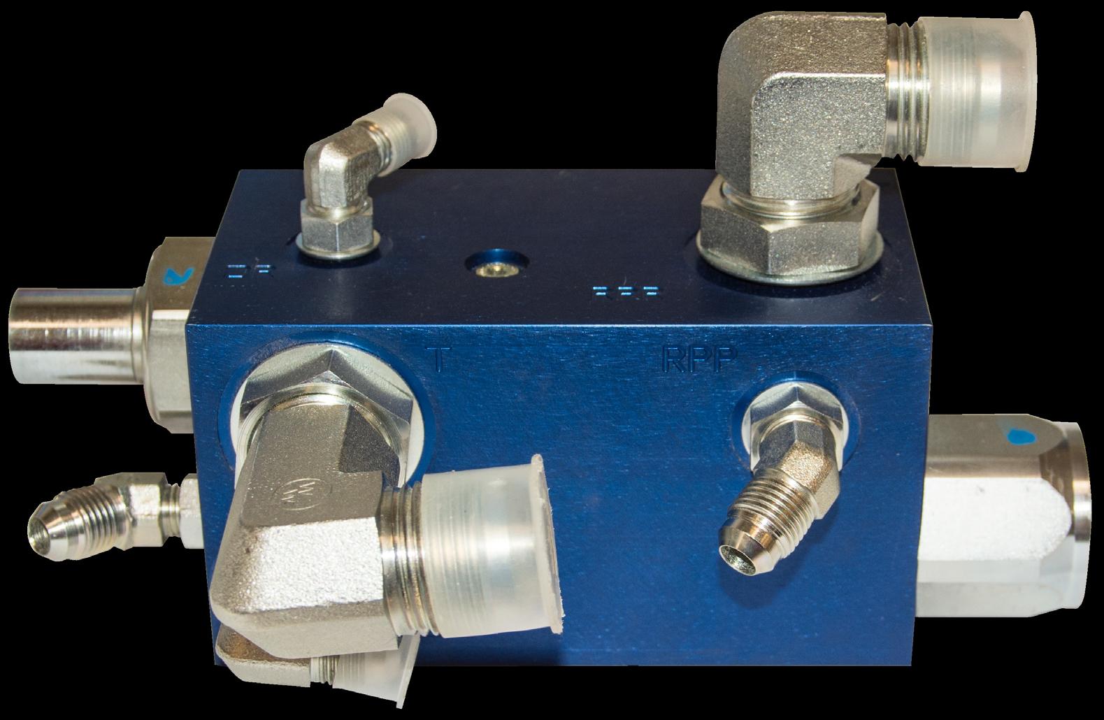
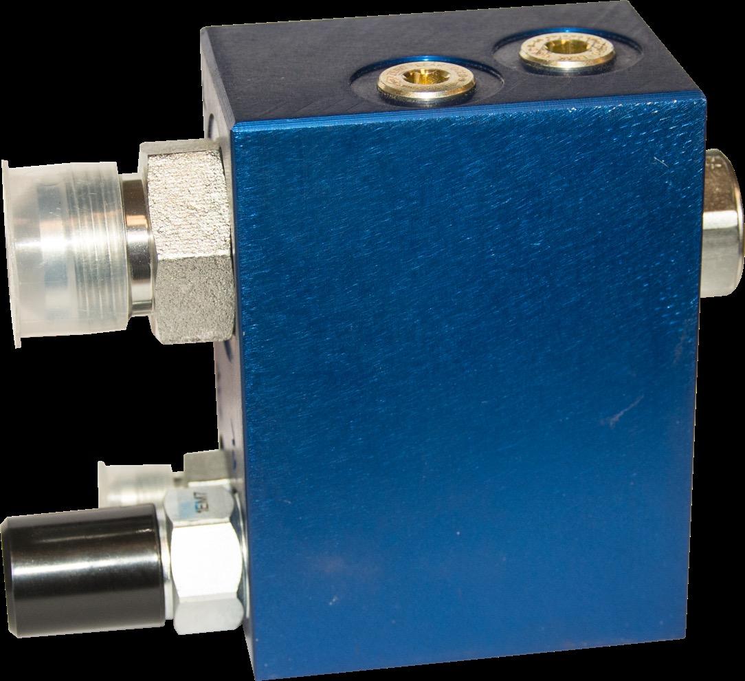
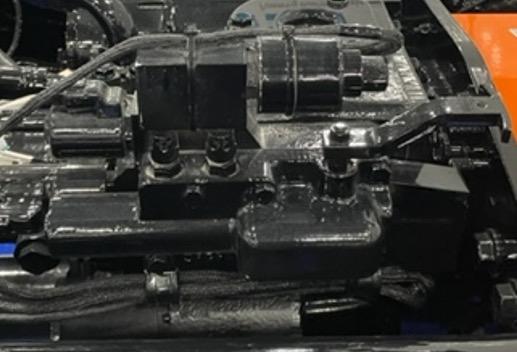
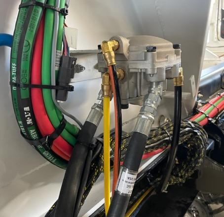
- Main Control “Combo” Block
Up/Dn Valve Axle Mid-Stop Valve (Option)
PRV2

Chute Lift Pilot Checks
Chute Up Flow Control
Setting: Bottom out and ¼ turn out
Chute Down Flow Control: ½ way out
Chute Down Manual Override
Chute Up Manual Override
Notes:
• Overrides located under coil caps
• Overrides dis-regard ALL safeties and proximity switches
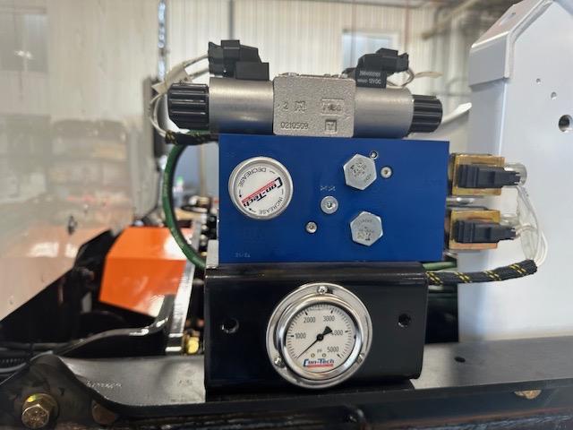
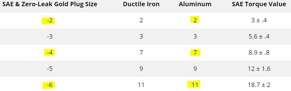
- Parker Valve Machine Screw Torque = 50 in lbs
System speed orifice located under axle mid-stop Parker valve
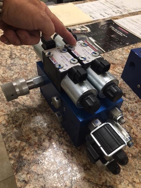
• Remove axle mid-stop valve
• Unthread orifice from manifold
• Remove Parker pump pressure hose AND fitting from “P” port
• Flush out port from top down
• Reassemble and test operation of trailer
- High Flow Block Contains:
- 3300 psi Relief Valve: 75 Gpm valve that clips pressure above 3300 psi ONLY on the downside of bridge circuit
- Check this valve if you can build trailer pressure in the UP pos but not in the down
- Pilot to Shift Valve: This valves tells which end of the bridge cylinder to apply flow/pressure to based on whether it sees signal pressure or not (from axle up/down valve
Signal pressure

Regulated Pressure
Signal pressure
Up = 0 psi
Down = 3000 psi
Regulated Pressure from PRV2 Valve
Extend Cyl (Down)
Retract Cyl (Up)
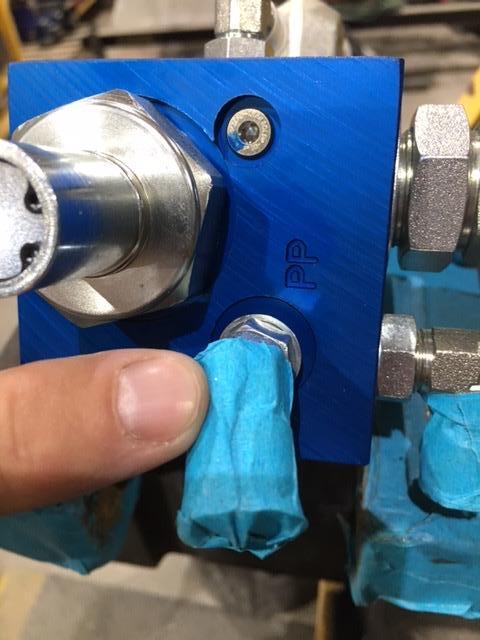
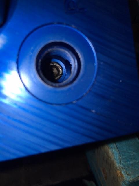
Symptom: Trailer won’t react to up/down command but pressure stays up
• Remove “PP” hose and fitting
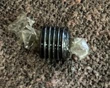
• Located under fitting is orifice plug
• Remove orifice and inspect
- Located on rod end of bridge cylinder barrel
- The counter balance block is simply a safety valve (ie: metered check valve) for controlling the lower of the trailer should there be a loss of hydraulic pressure
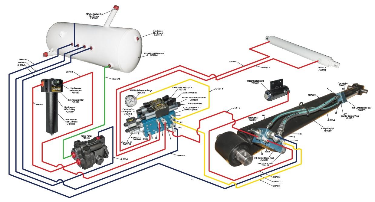
- Con-Tech uses Danfoss hoses and fittings
Dash system for hose sizing is base on 1/16”
Gauge Hoses -4 = ¼” ID (GH781=6500 psi)
Chute Hoses -6 = 3/8” ID (GH781=5300 psi)
BK Parker Pump/XD Pony Pump Press -8 = ½” ID (GH781=4500 psi)
BK Cyl (short hose) -12 = ¾” ID (GH781 = 3500 psi)
BK Cyl Return -12 (FC619 = 305 psi)
Main Pump to Motor High Press -16 = 1” ID (EN856 = 5100 psi)
Main Pump Suction -16 (FC619 = 245psi)
- .67cu in gear pump powers chute system
- Right hand (clockwise)rotation – REAR of cab UNLESS Cummins X-12
- Left hand (counter clockwise) Front bumper mount OR Cummins X-12
NOTE: Larger port is AWAYS the sucton port
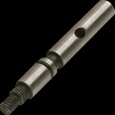
Shaft: 5/8” x 9
- Open center manifold manifold (#765100)
- Up-Down Coils/Cartridge (Cart #765092/Coil #765093)
- 2200 psi relief valve (#765095)
- Down flow control (#765097) In=Faster / Out=Slower (PFC)
- Up flow control (#765091) In=Slower / Out=Faster (Needle)
- Base Line Settings for Both - ½ way out
- Pilot Check Valve (#765096)
Key: Pilot check valve is what holds the chute up in the air (back pressure from cylinder pushes check valve shut
Troubleshooting
• If chute fades back down, remove and inspect check valve
• If just replaced block and chute fades, check chute hoses!!
Testing: The ONLY place you can install (deadhead)a pressure gauge is in the chute lift hoses (to test pressure)
System pressure is set to 2200psi
NEVER install a test gauge here unless you are Tee’d into the hose
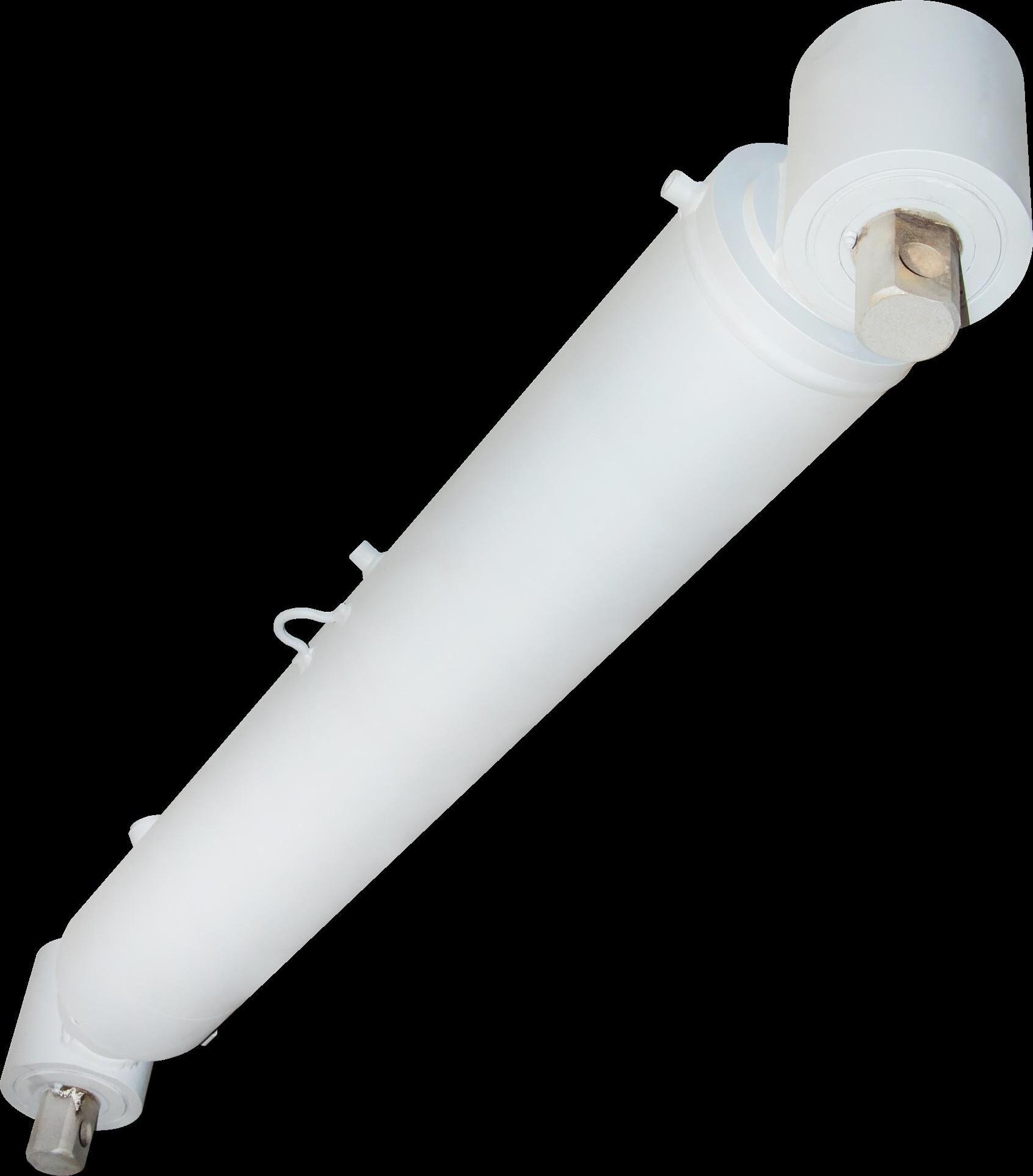
- Con-Tech uses ALL double acting cylinders for the chute lift applications
- All Con-Tech cylinders have internal
- This flow (velocity) is set @ 4.0 4.0 gpm to leave the cylinder unrestricted & allows the cylinder to lower
- Any flow > 4.0 lock up and stops the dropping of the chutes
- Causes of cylinder locking up include: broken hydraulic hose, flow control open too far, air bubble trapped in cylinder
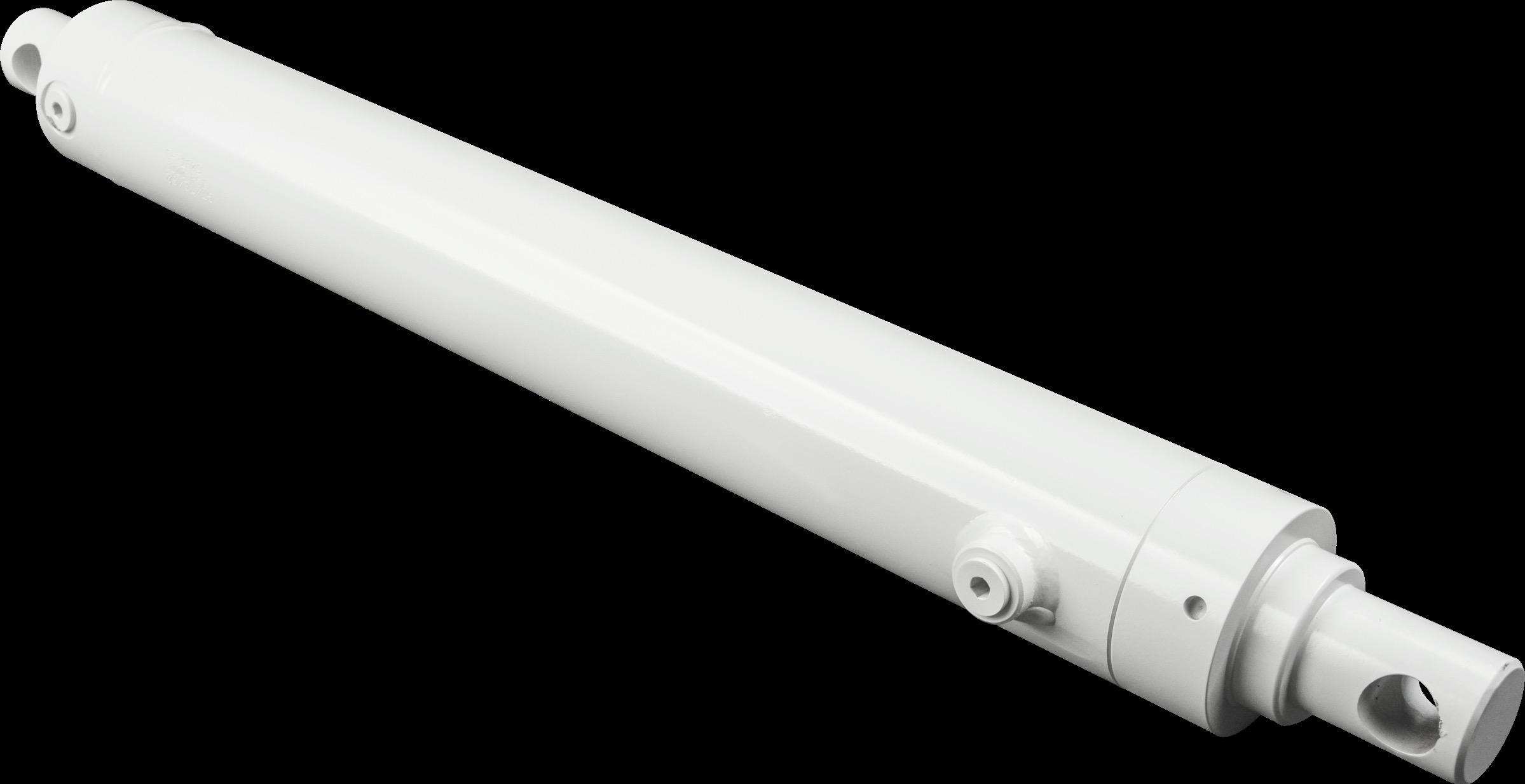
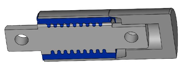
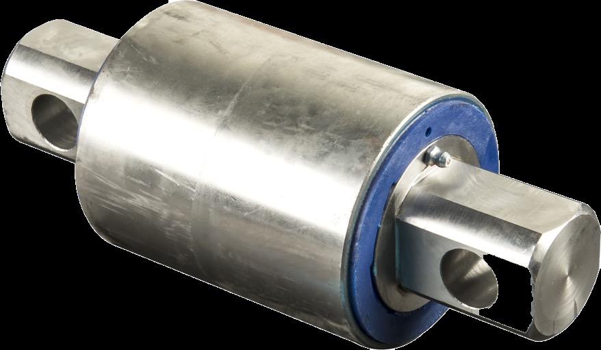
- Internal Nitrogen Accumulator
- Use nitrogen because dry, stable and NOT flammable
- Accumulator located INSIDE rod
- Charge to 1100 psi
- Utilize Atro bushings
- Must be greased via zerks
NOTE!
Cylinder MUST BE installed on truck AND trailer MUST BE in down position before charging the bridge cylinder
Bushing: 750051
Notes:
• Grease required to flush out contaminates
• WATCH for alignment “dots” to ensure entire bushing gets greased
• Some play/gap is normal between poly material and pin
• Bolts: 6” x 1” GR8, 450 ft/lbs
Press Tool: 740101
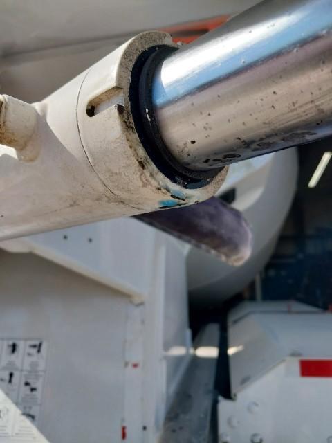
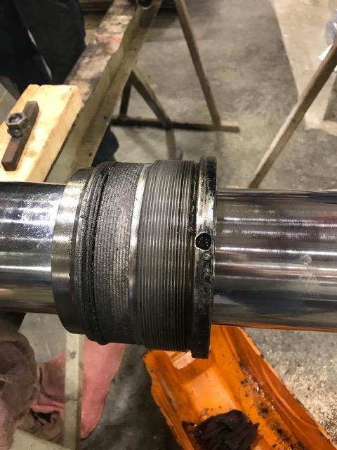
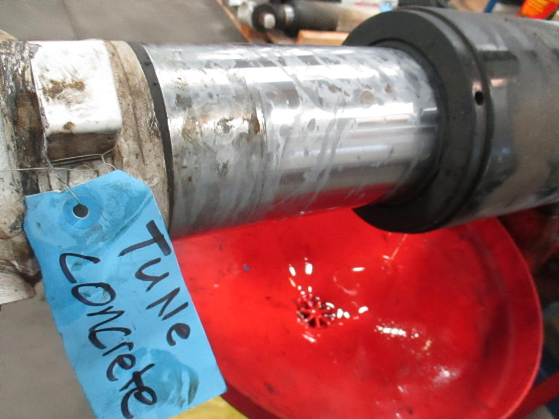
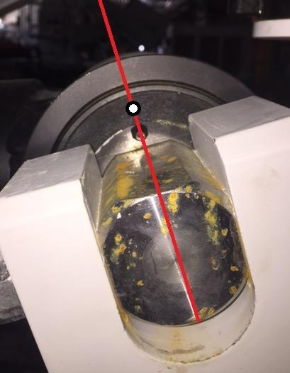
- Set screws located here
- There are TWO in there (inner/outer)
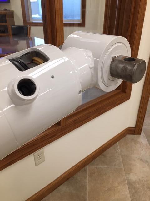
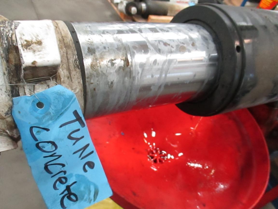
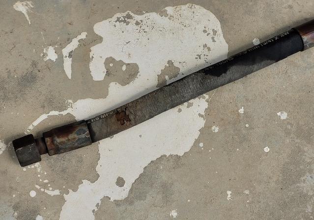
- Forgot to remove head gland set screws located in barrel !!!!!
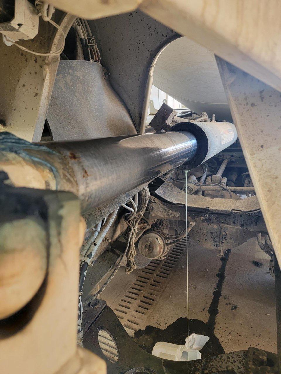
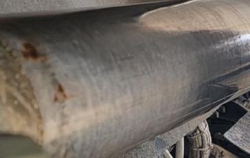
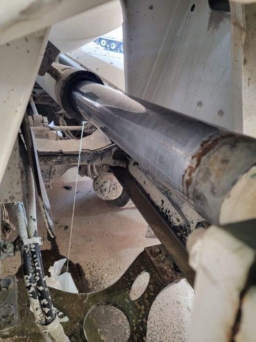
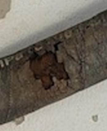
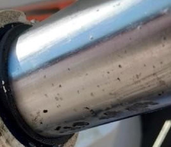
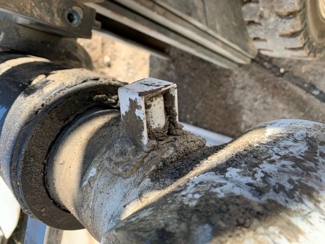
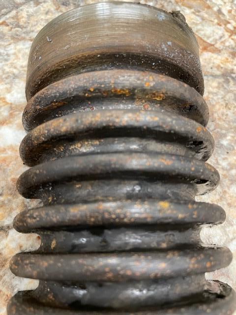
• Cylinder ran with Kevlar® protective boot
• Evidence of concrete slurry underneath rod clamp
Trailer Pivot Bushings
• Zerk and “Divot” align towards front of truck with trailer down
Cylinder Bushings
• Zerk and “Divot” align as shown so to line up with trailer down
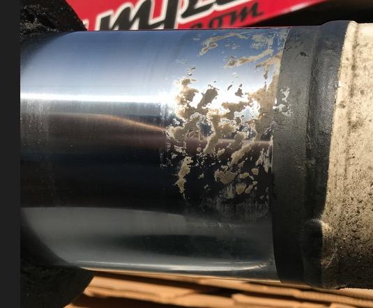
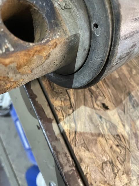
Lack of grease causes rusting and pitting of pin. Formation of rust “locks” pin to polyurethane and tears polyurethane from the outer sleeve
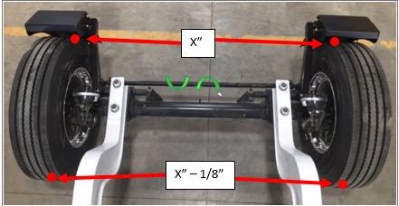
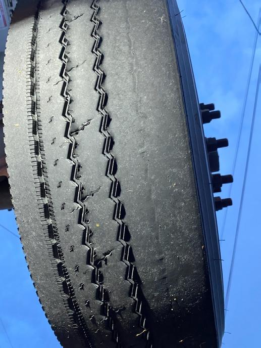
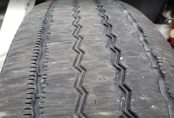
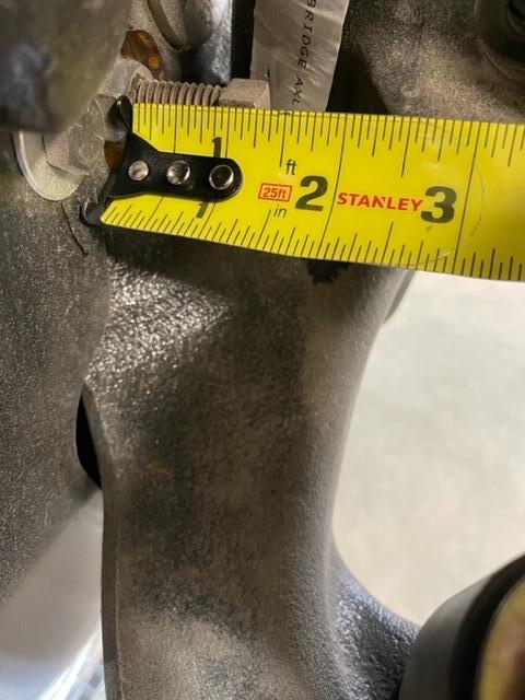
Causes of trailer issues/tire wear
• Toe In (1/8” Toe In)
• Steer Stop Adjustment
• Side Loading
• Tire Scuffing
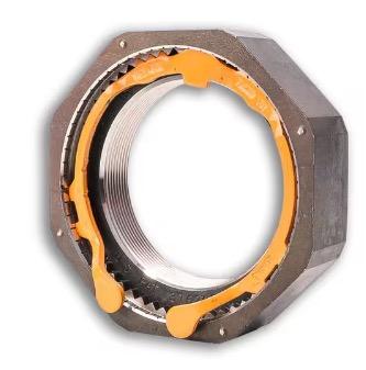
• Locknut Part #791020
• Inner Seal #791050
• Inner Bearing #791024
• Inner Race #791023
• Outer Bearing #791022
• Outer Race #791021
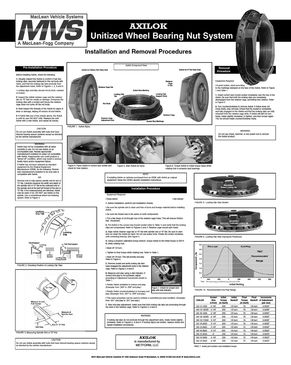
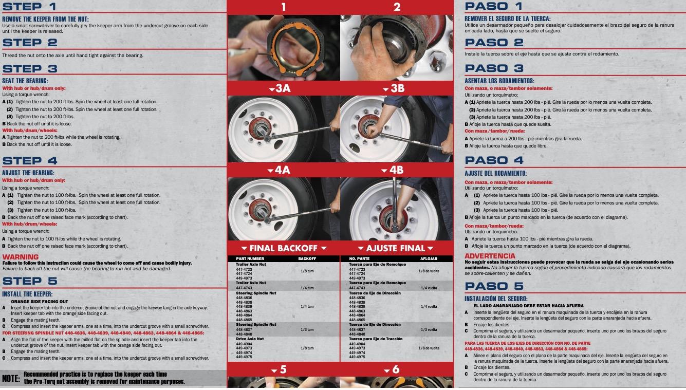
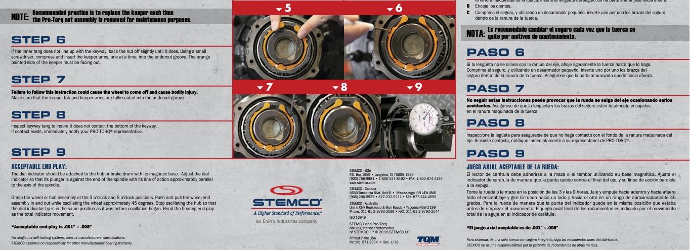
NOTE: Bearing preload after nut adjustment .001”-.005” (end play)
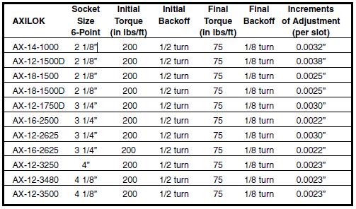
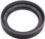
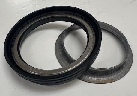
Inner Wheel Seal #791050 (New)
Stemco Pro-Torque Spindle Nut #791053
See installation instructions on following pages or google “Stemco Pro-Torque Spindle Nut Torque Chart”
Inner Wheel Seal with Repair Sleeve #791014

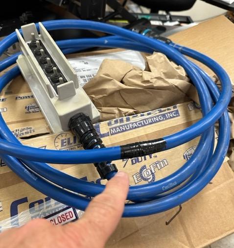
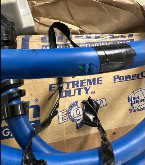
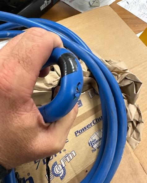
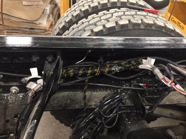
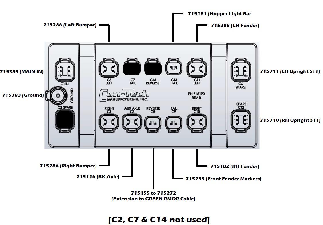
• Con-Tech Harnesses
• Pre-Aug 2018: Standard 1-piecebraided harness bottom of cab to rear pedestal
• Post-Aug 2018: Armor Tech Harness System
• 1 piece braided from cab to front pedestal only
• Segmented (red, orange, green)rubber cables from front pedestal to rear pedestal
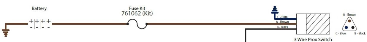
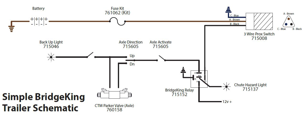
When prox switch is “made”, it fires a12V+ out When prox switch is NOT made, output signal is 0V+
Where are they…..
Chute Center (at bottom of main chute)
Bridge Trailer Motion (located inside driver frame rail near trailer pivot casting
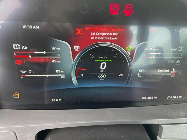
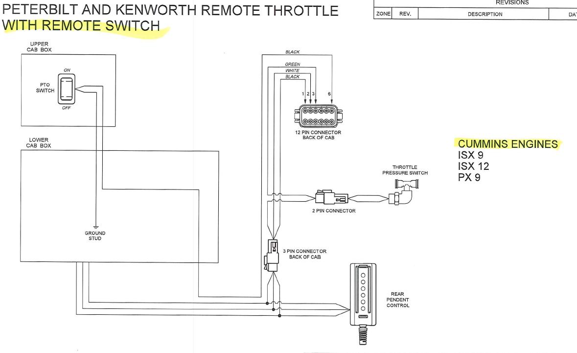
- Only on mixers with corded rear pendants!
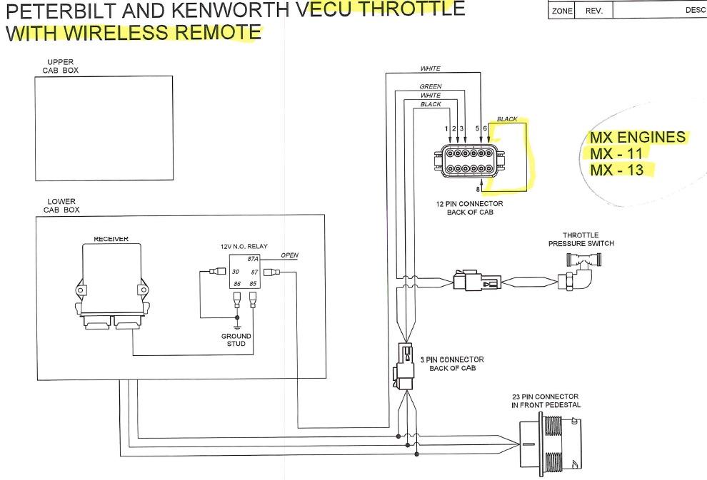
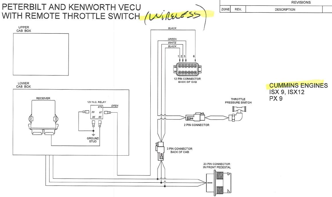
- If mixer is wireless, turning ON the handheld activates the PTO mode
- If PACCAR w/ MX engine, when PTO mode is activated, the accelerator pedal is “ dead”
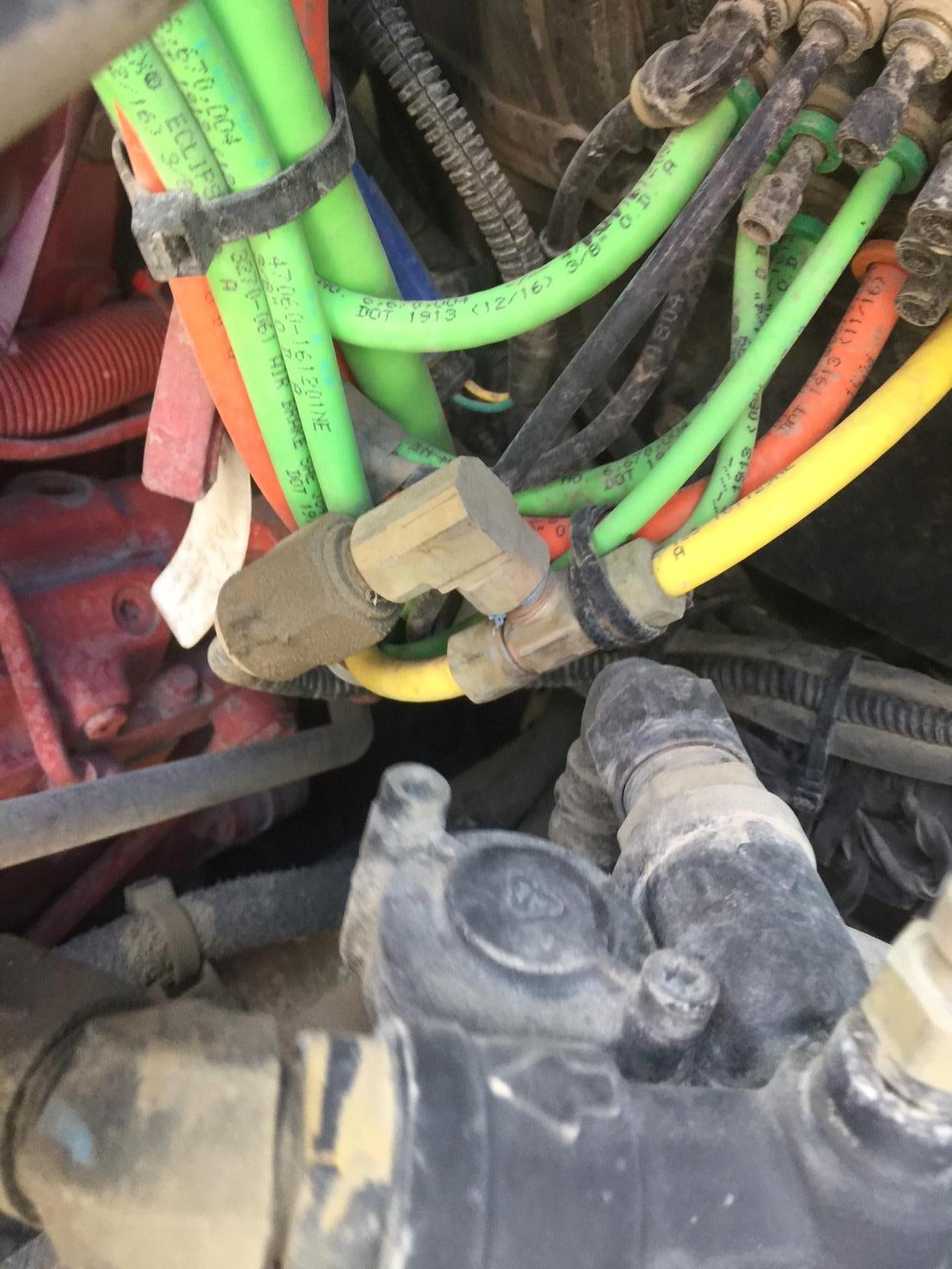
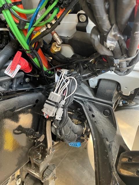
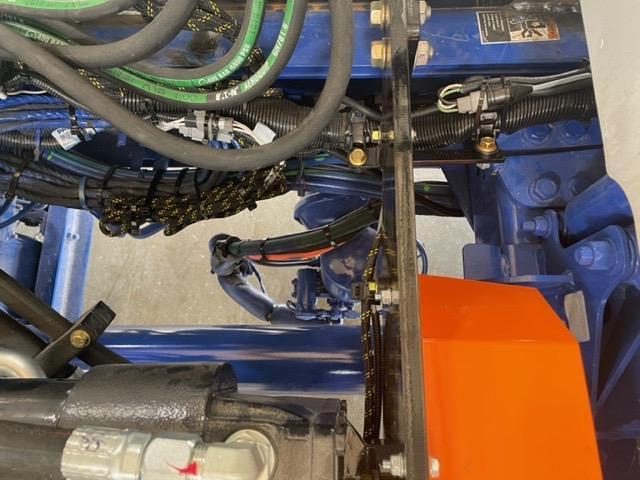
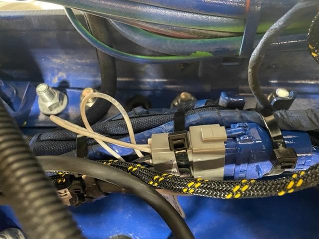
• In park brake signal (yellow) air line
• Paccar = Firewall or Driver Frame Rail (back of cab
• MACK = Inside driver frame rail (back of cab)
• Others = Typically behind park brake hand valve
• Normally Closed (NC) switch at 0 psi
• Opens at 40 psi when park brake is held OFF (not applied)
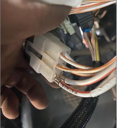
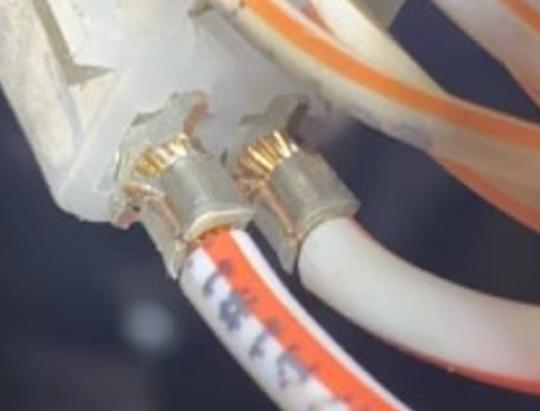
• For diagnostic purposes ONLY, you can place a jumper wire between the two terminals on the harness plug and re-test
• KW/Pete chassis, located on firewall, engine side/driver side
• Mack chassis, located inside driver’s frame rail, back of cab
• Western Star are located behind the trim panel in front of the passenger seat (where the glove box would typically be)
• Freightliner and others, typically behind park brake hand valve
Set-Resume Switch
Located in Dash
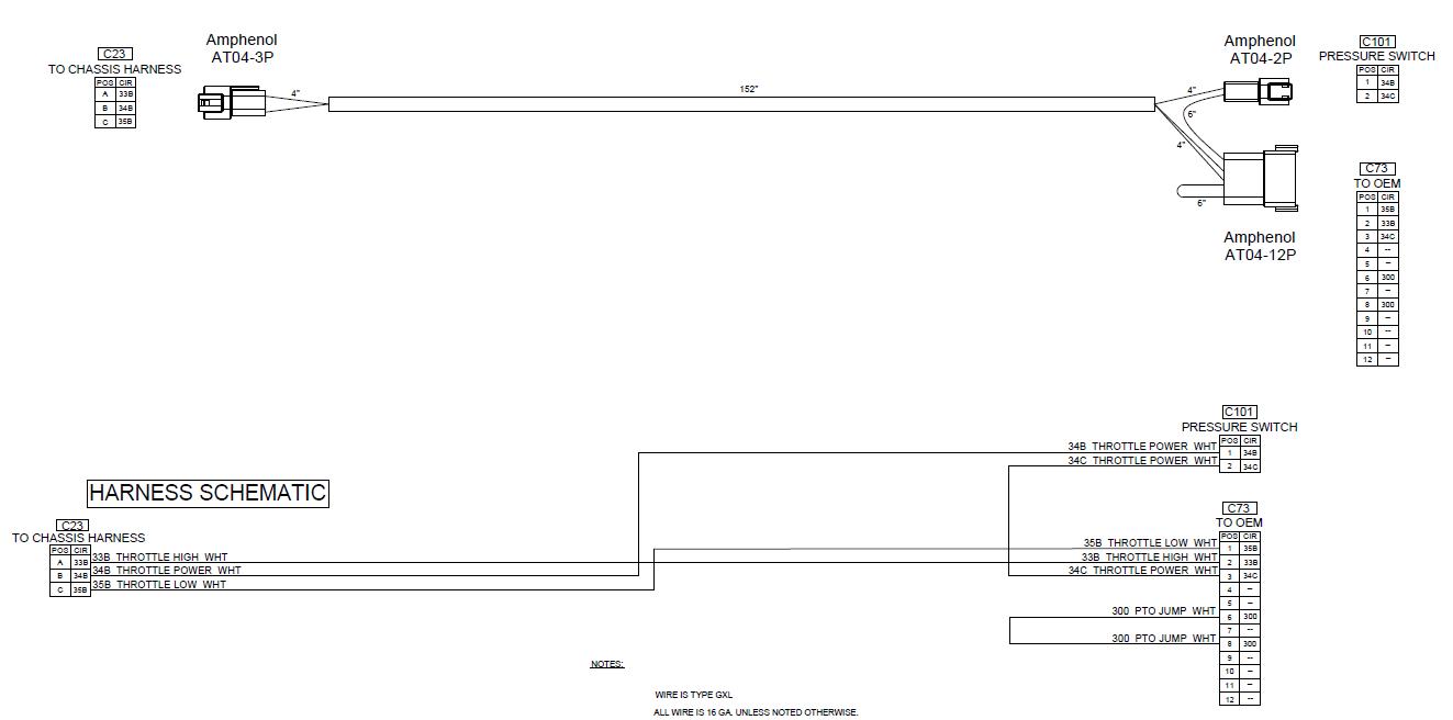
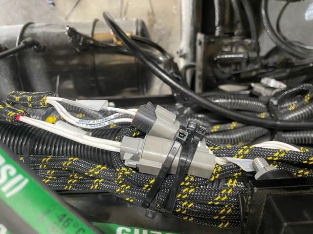
2 pin (12ga) power & ground
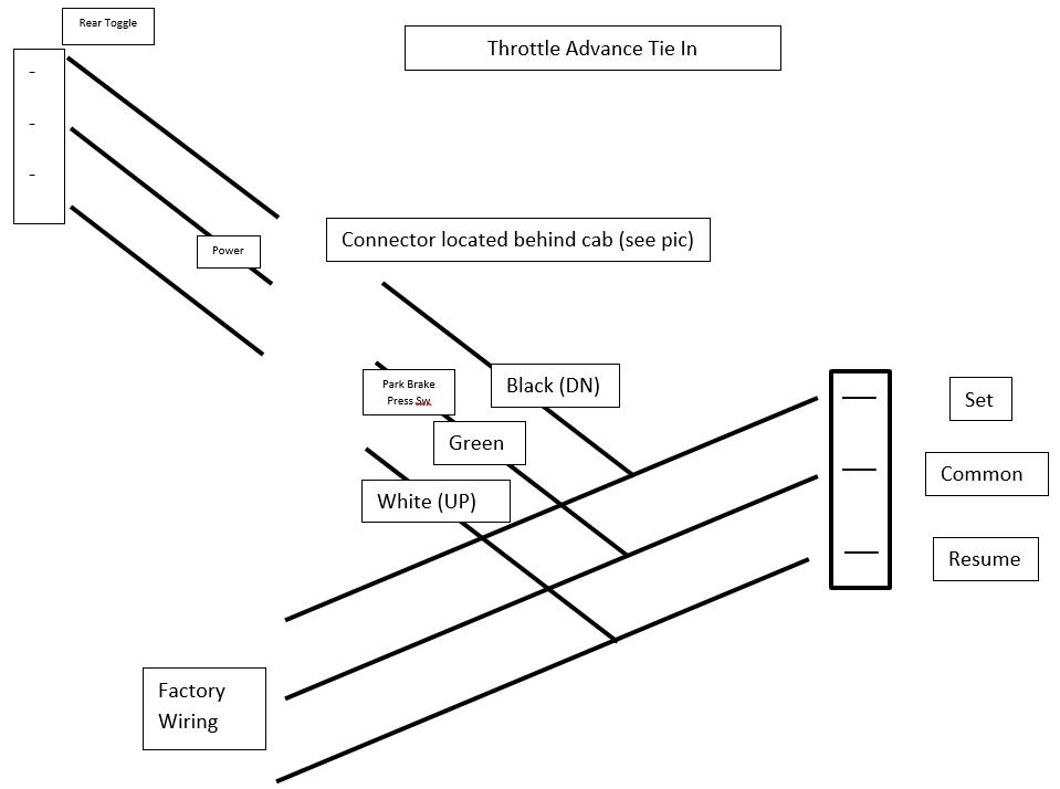
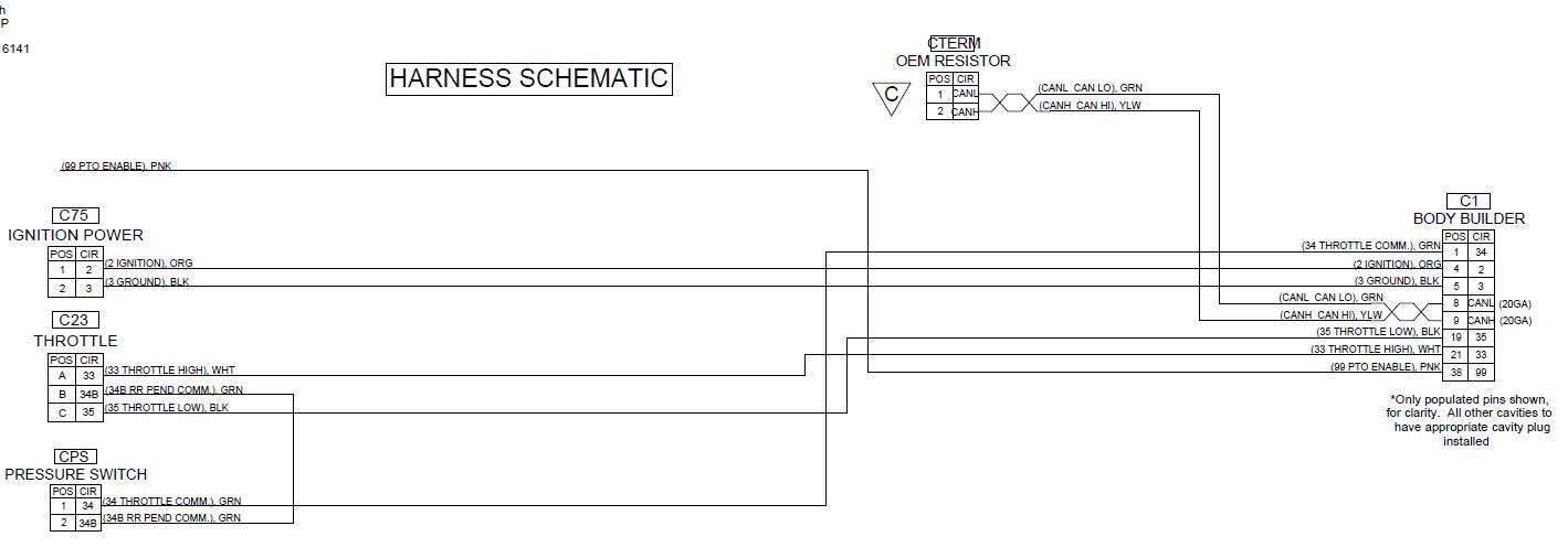
3 pin throttle
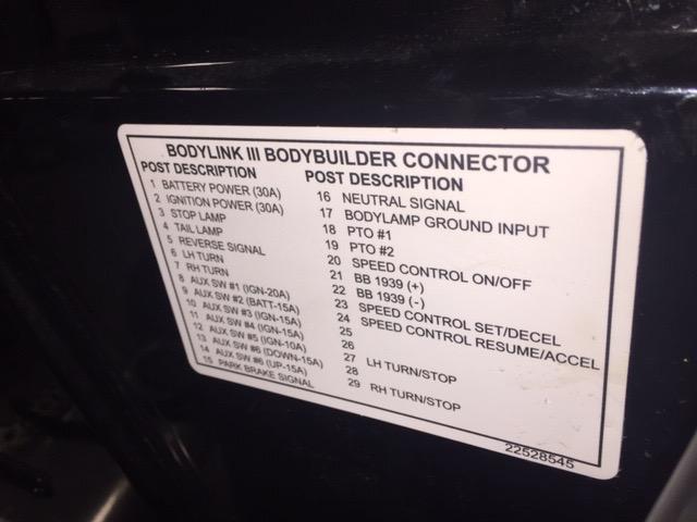
Remote bodybuilder plug contains throttle up/down wires as well as the remote PTO enable signal wire
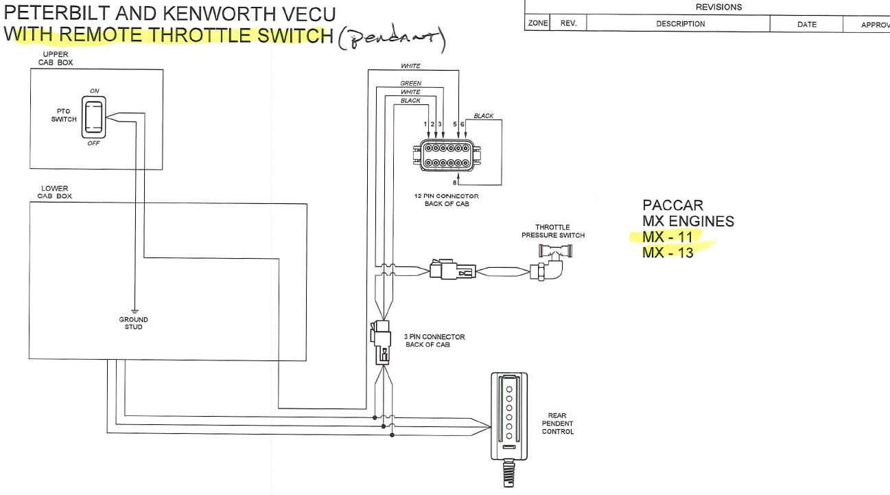
GROUND (Pin 3)
UP=5V+ (Pin 2)
DOWN=5V+ (Pin 1)
GROUN D
DOWN=3V+
UP=3V +
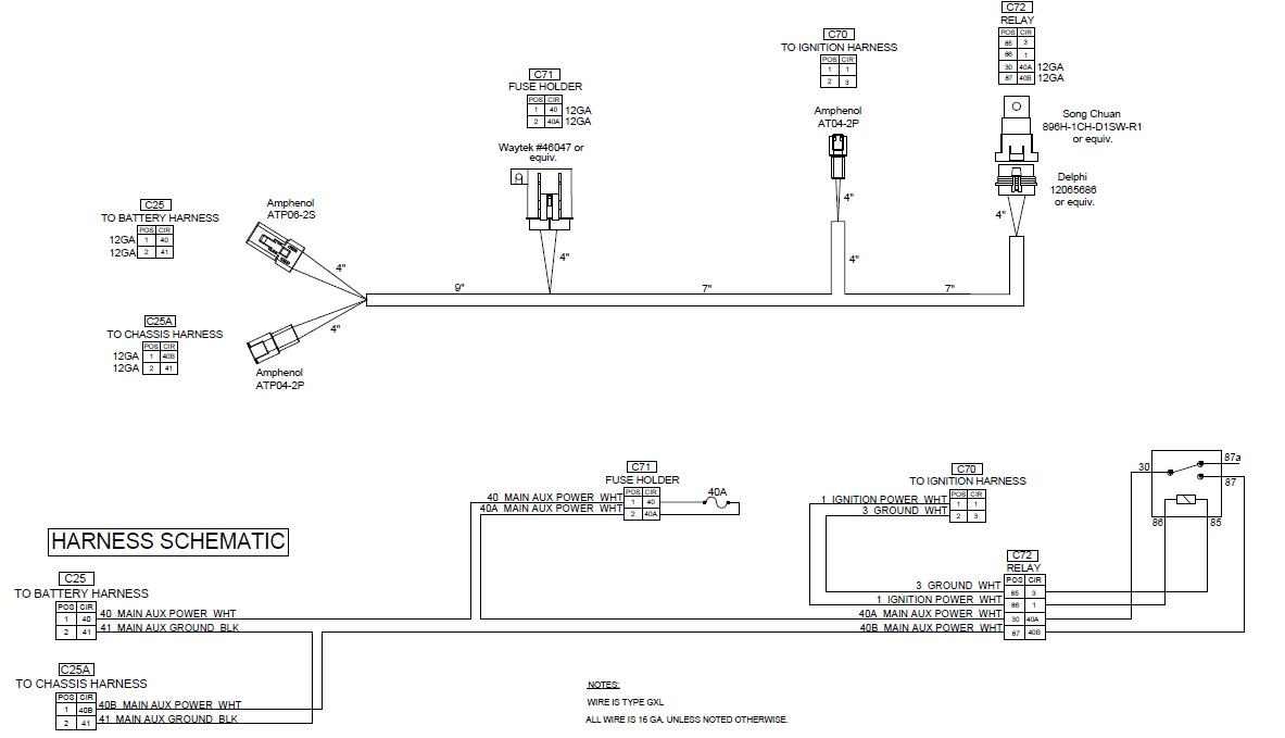
Relay is triggered by accessory power from chassis (wire located under dash) above driver’s left foot
50 Amp relay & 40 Amp Fuse
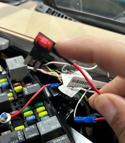
• Make sure ignition switch is springing back to “RUN” position. MACK bodybuilder plug will NOT go hot (12V+) till the ignition cylinder returns to the RUN position. If ignition cylinder remains in START position, starter will kick out and everything will work just fine.
• Check MACK harness connector under dash. There is a single wire connector that connects the fuse box harness to the bodybuilder plug harness located above steering column in dash. VERY common for this to come disconnected!!!
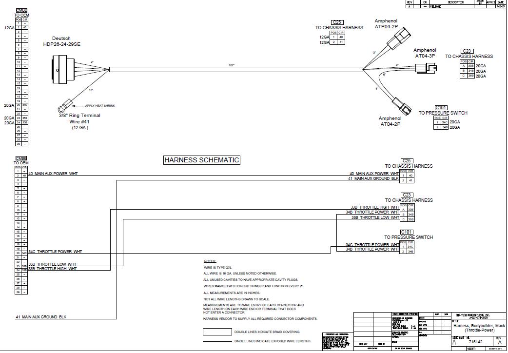
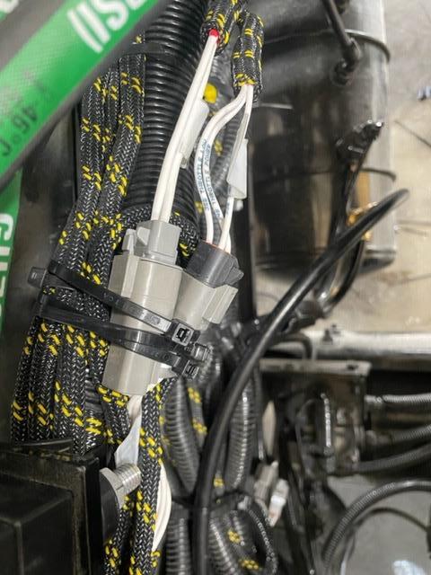
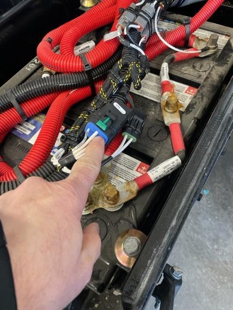
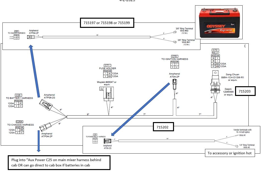
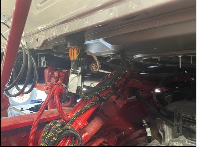
Main power(12ga wires) coming from power relay in battery box or BodyLink III connector (if MACK)
Throttle (3 wires)
Located at Back of Cab (Driver Side)

Run jumper wire direct from pos battery stud to power stud on back of fuse panel (located in center mixer console)
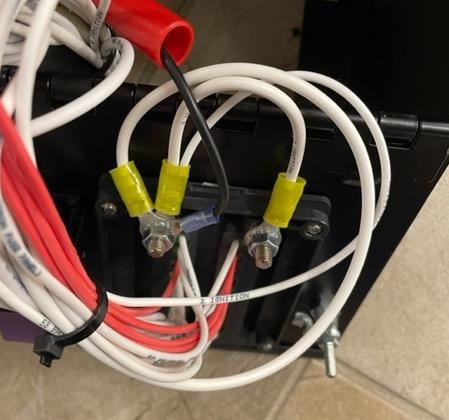
Throttle would raise on engine as soon as PTO switch was turned ON (on the mixer console)
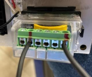
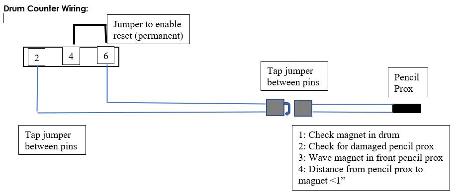
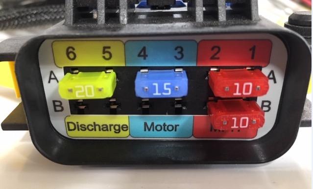
2 wires that come from pencil prox switch are hooked to terminals 2 & 6
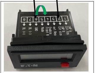
= Jumper wire from terminals 4-6 to enable front reset button
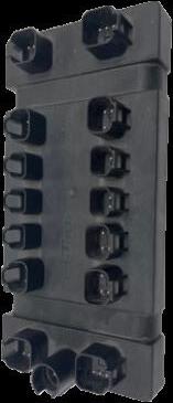
Module located inside driver’s side of rear pedestal under cover as shown
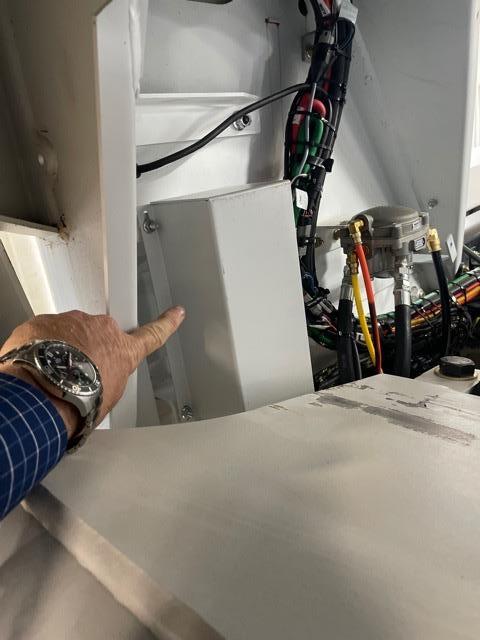
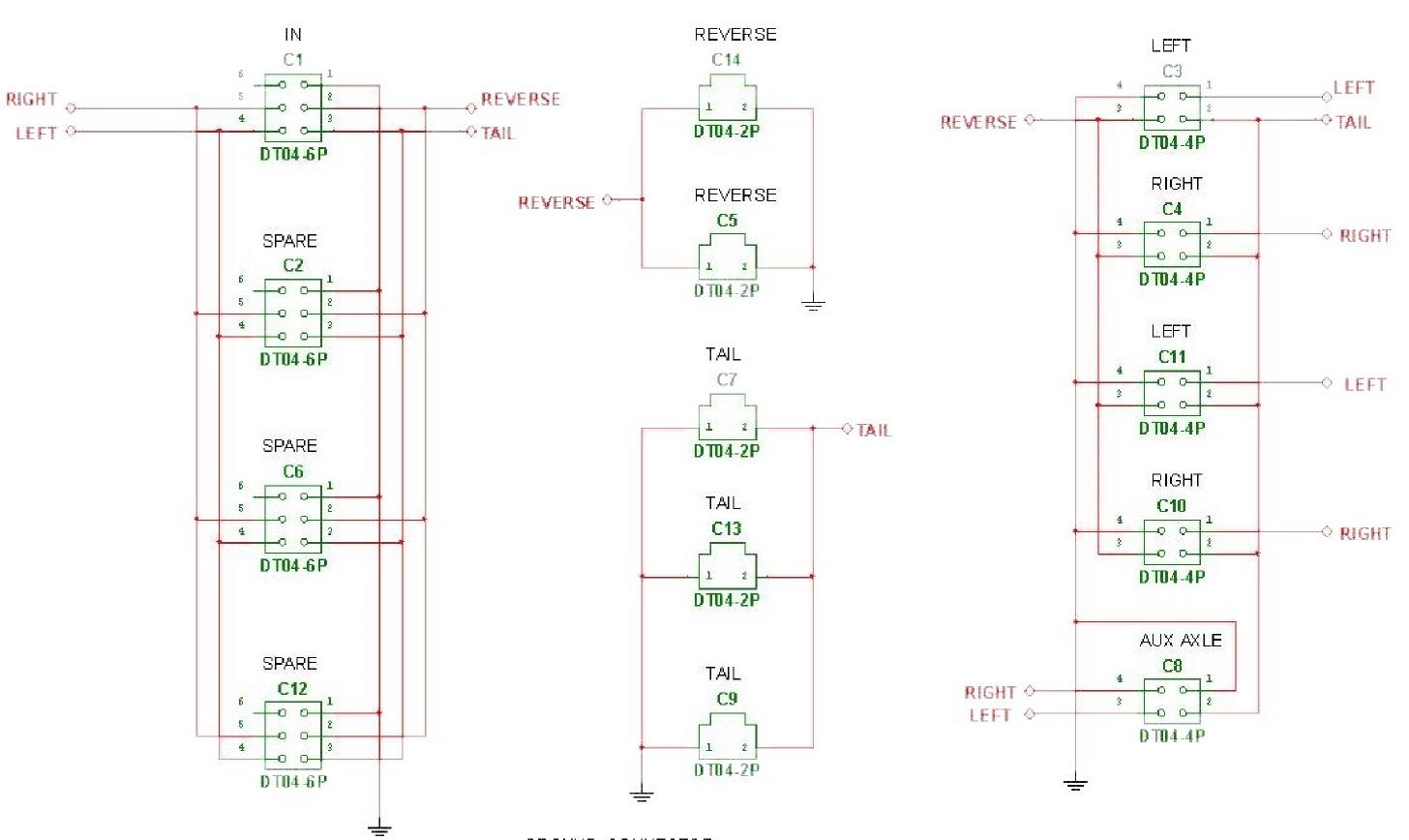
• ALL chassis manufacturers give us a lighting output connector inside the driver’s side frame rail behind the rear dual.
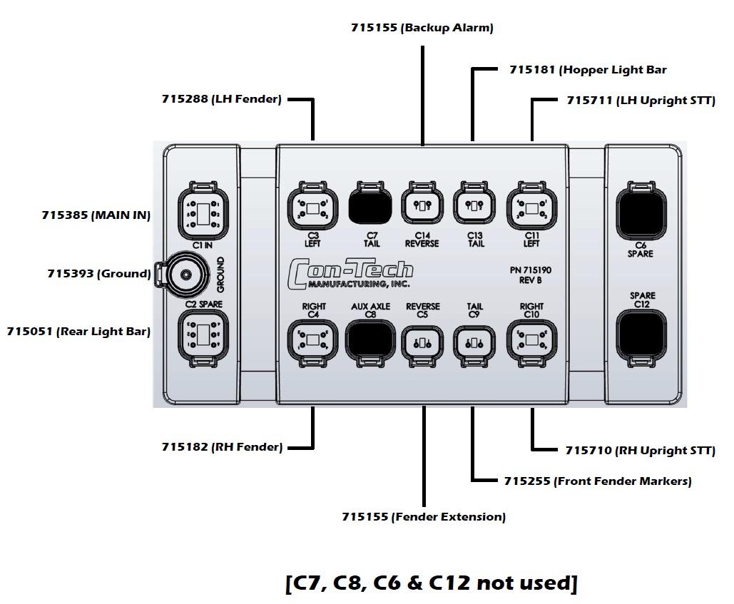
• We hook directly into these outputs and run into our lighting distribution “module”
• This module replaces the old “spider” harness
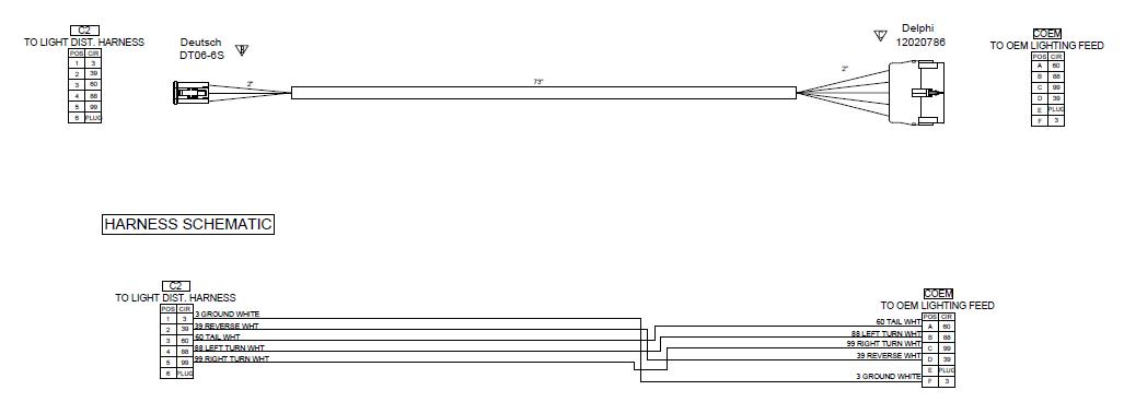
To Light Distribution Module
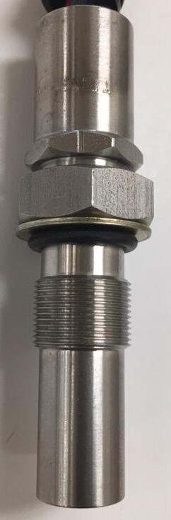
Chassis Harness End
“Quad Sensor: Relays drum speed and direction back to controller
Sets drum speed while in constant speed
CW=Faster
CCW=Slower
Located in lower mixer console
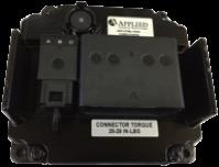
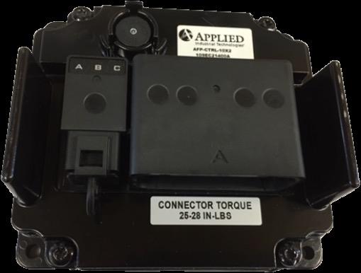
Constant Speed Module: Process drum speed/directio n info from quad sensor
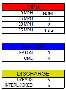
Configurator: Fuse location sets software for interlocks, hyd motor and truck mph for constant
Constant Speed Valve: Bleeds off charge pressure to charge servo can to destroke pump
POST JAN 2020
• Vehicle speed for activation
• Type of hydraulic motor
• Discharge switch operation
• Maintains constant drum speed regardless of engine RPM
• Drum speed can be set to 1-3
• May or may not come with optional discharge signal lock out
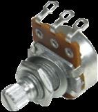
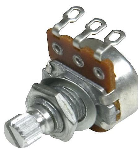
Rheostat (inside cab box) sets drum speed while IN constant speed mode
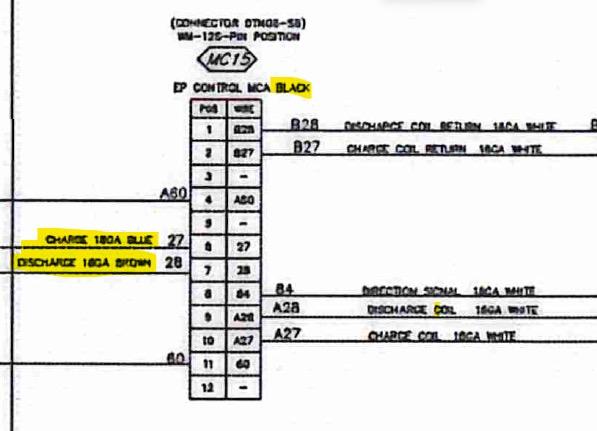
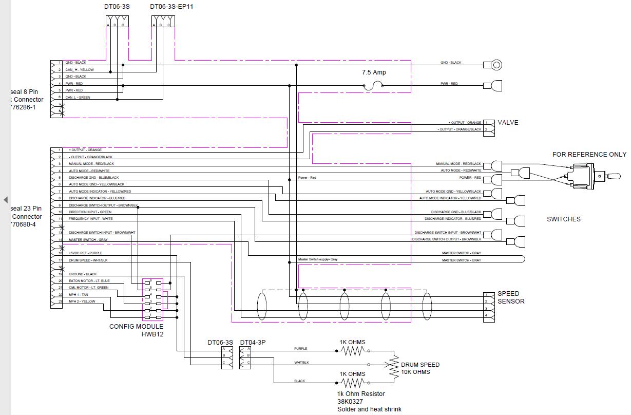
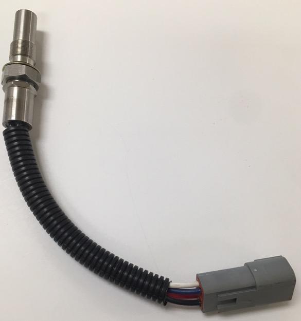
• Senses speed and direction of motor shaft (drum)
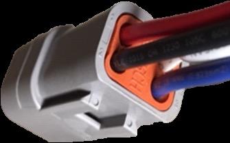
• Wiring colors
• Red (pin 1) = 12V+
• Black (pin 2) = Ground
• Blue (pin 3) = Drum Speed
• White (pin 4) = Drum Direction
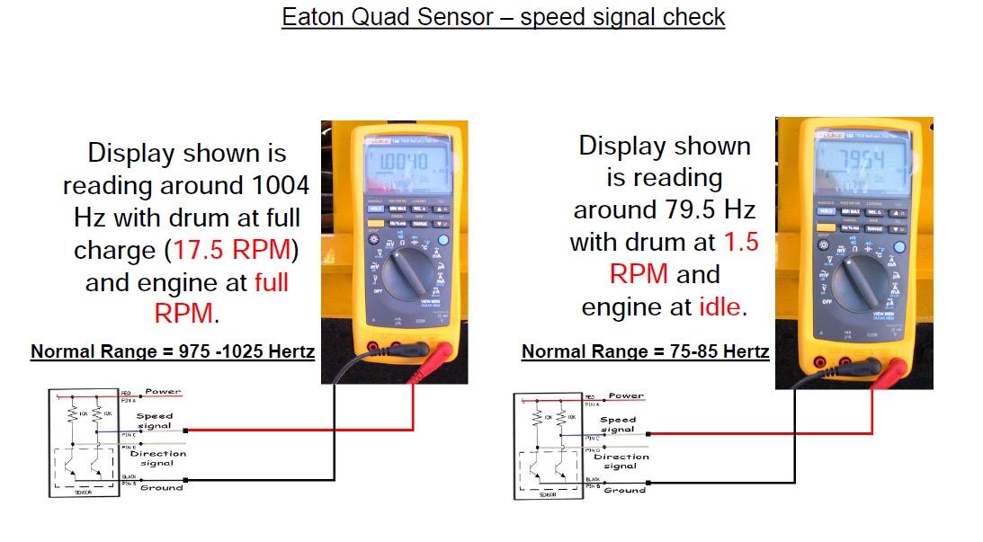
Testing
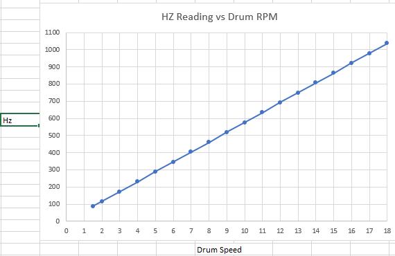
Drum Speed: With multimeter set to Hz
• Back probe pin 3 (blue) to pin 2 (black) and turn drum
• 1 Drum RPM = 58 Hz
• 18 Drum RPM = 1044 Hz
Drum Direction: With multimeter set to 12V
• Back probe pin 4 (white wire) to pin 2(black ground)
• Should toggle on-off (0-3.4V)when drum changes direction
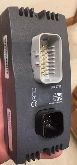
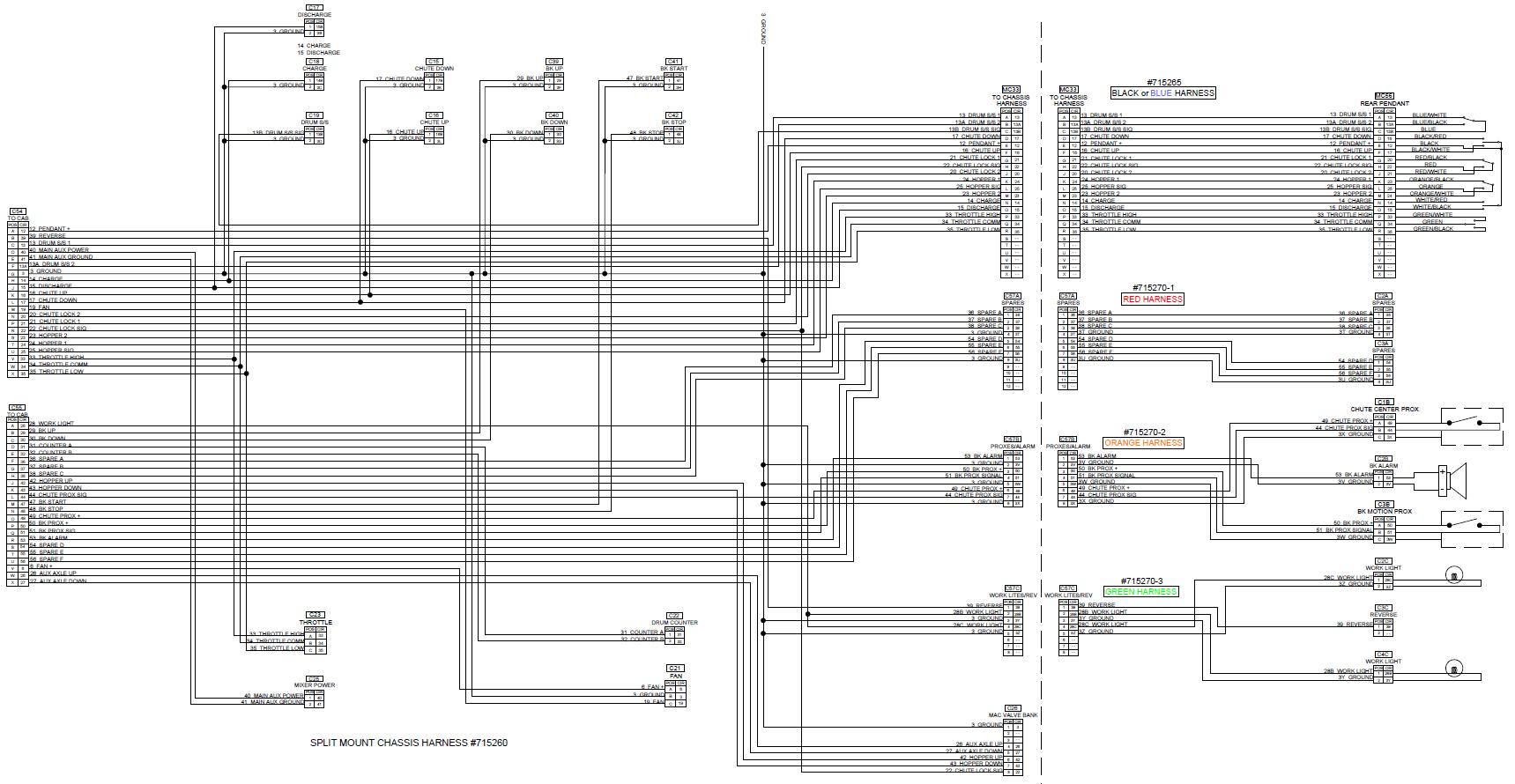
Post-2018 Armor Tech Schematic (on USB stick)

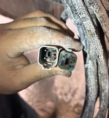
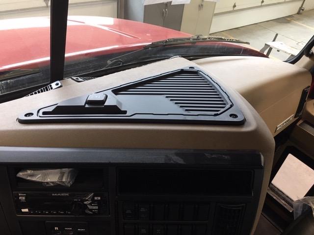
IF used as a phone charging port, have seen:
- Multiple Chassis Codes
- Multiple Elite Codes
- Drum inadvertently go into discharge
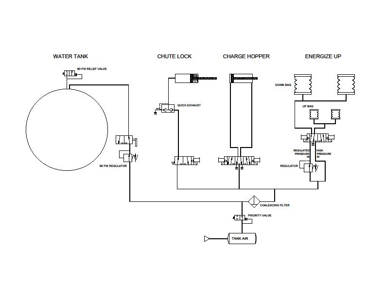
- Con-Tech uses MAC air solenoid valves
- While a very good valve, they do require a certain amount of care
- During summer months or if you are in the south, you MUST drain the coalescing filter DAILY
- The drain is a twist valve at the bottom of the filter bowl
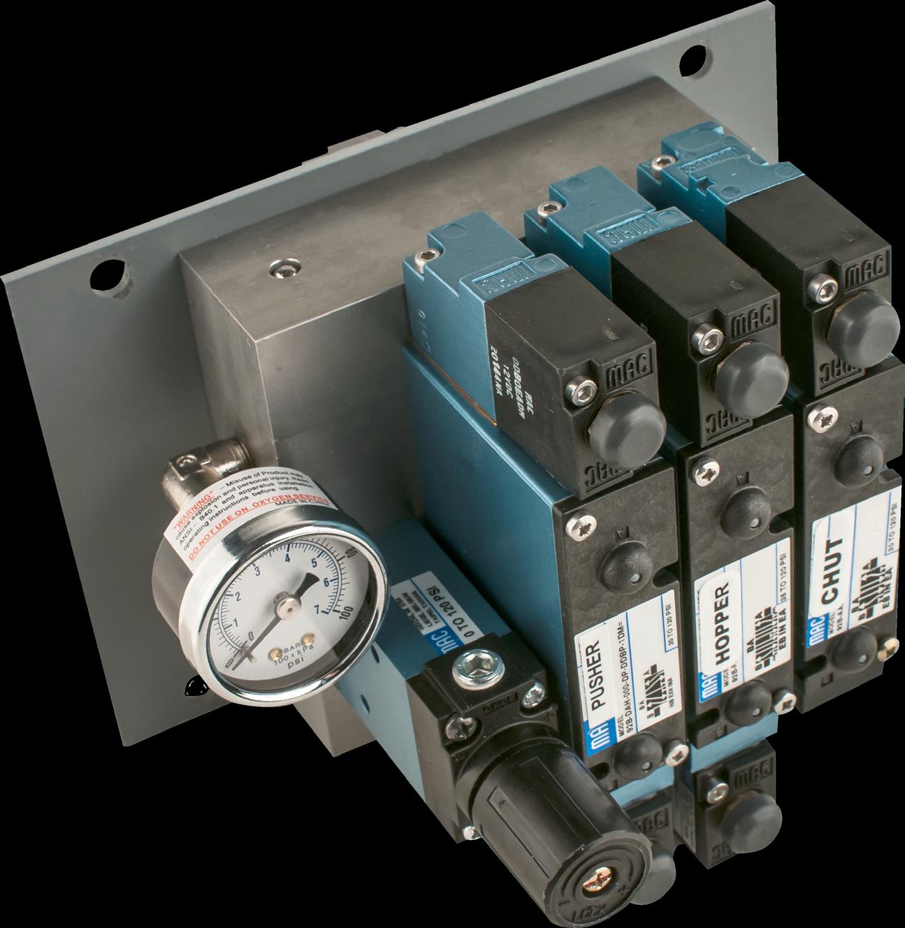
- Main Components
- Manual overrides
- Overrides ONLY work if NO Power
- 0-160 psi pusher axle gauge
- Pusher regulator
- MAC valves require very little maintenance
- For colder climates OR for trucks that will be parked for a considerable amount of time, MAC recommends the following
- Remove air supply line and place approximately 1 Tbsp (cap full) of ATF in air inlet airline
- Cycle all valves with manual overrides
• Will NOT release air to mixer system until truck tanks build to 75 psi
• Regulated (non-adjustable 60 psi)air goes to water tank
• Non-Regulated air goes to MAC valves
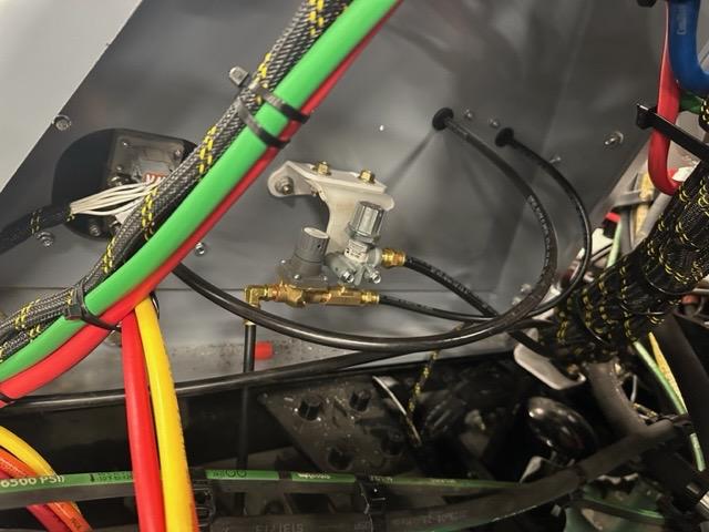
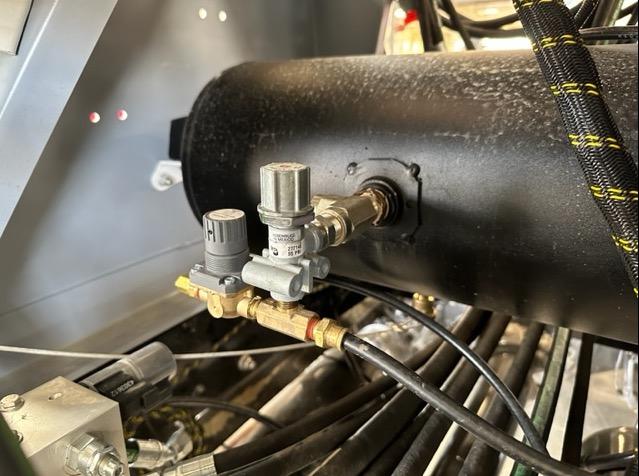
- Mixer air functions will NOT operate till 85 psi reached in truck tanks
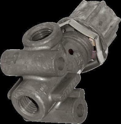
- Holdback valve is responsible for this
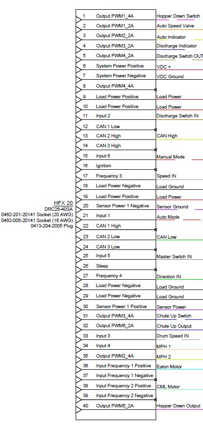
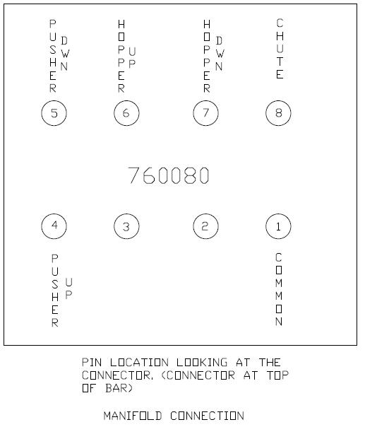
- Electrical pin layout on back of manifold connector
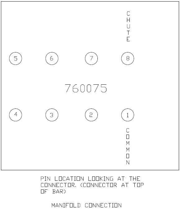
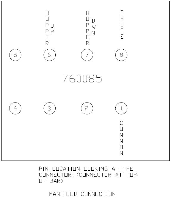
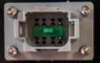
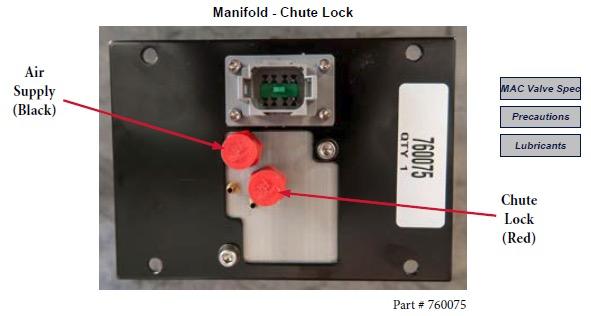
Air porting on back of manifold
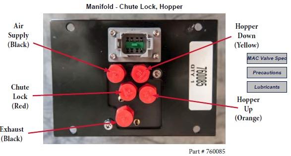
Air porting on back of manifold
Air porting on back of manifold

MUST
Part # 760030 (60 psi)
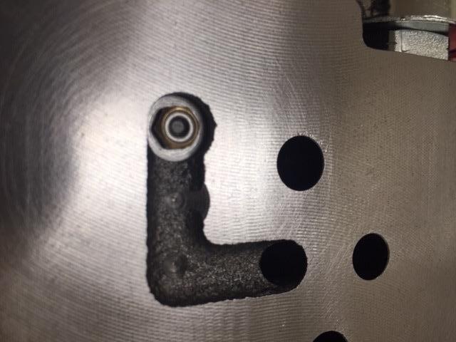
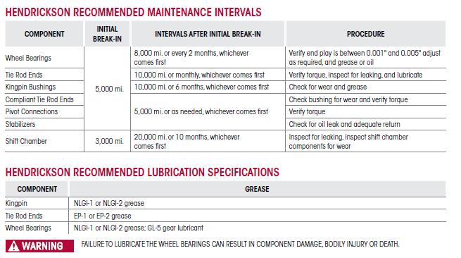
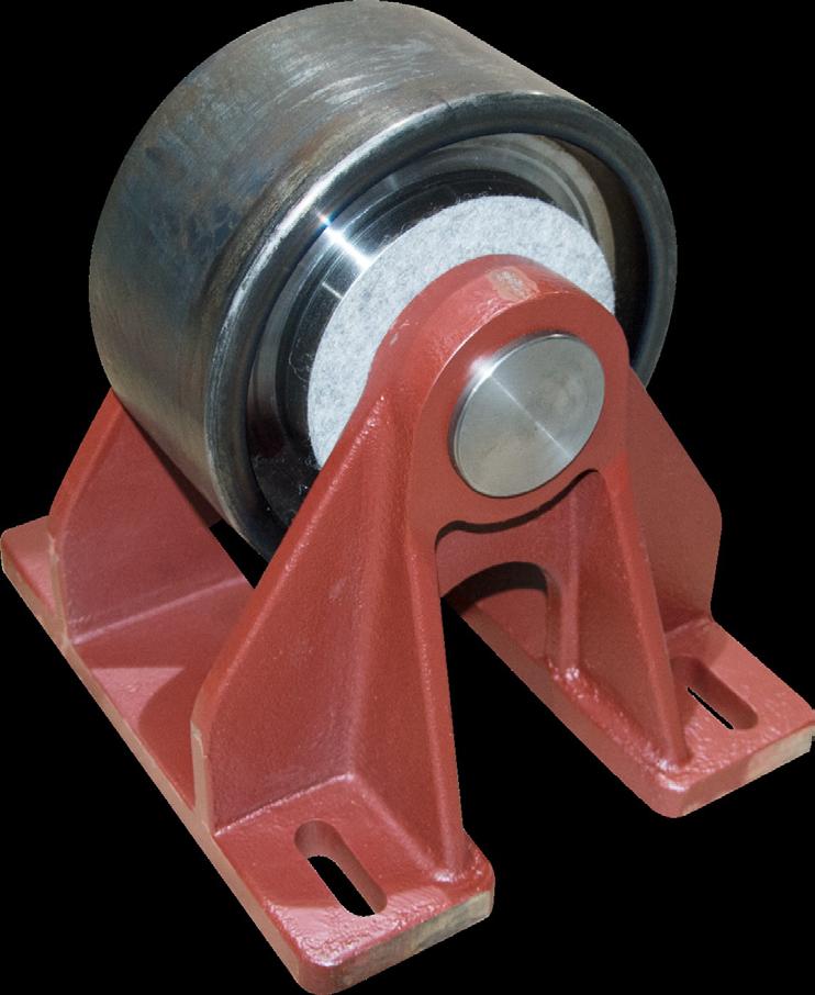
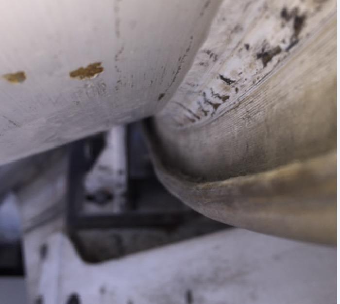
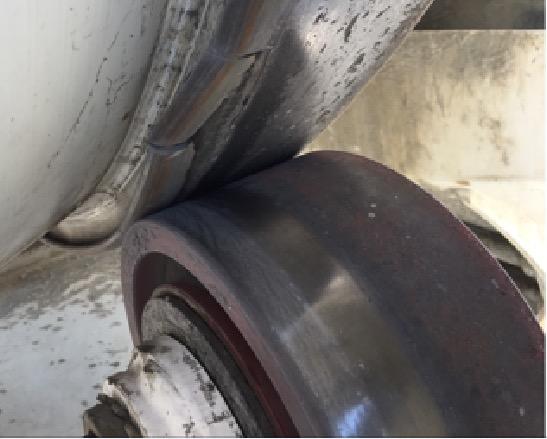
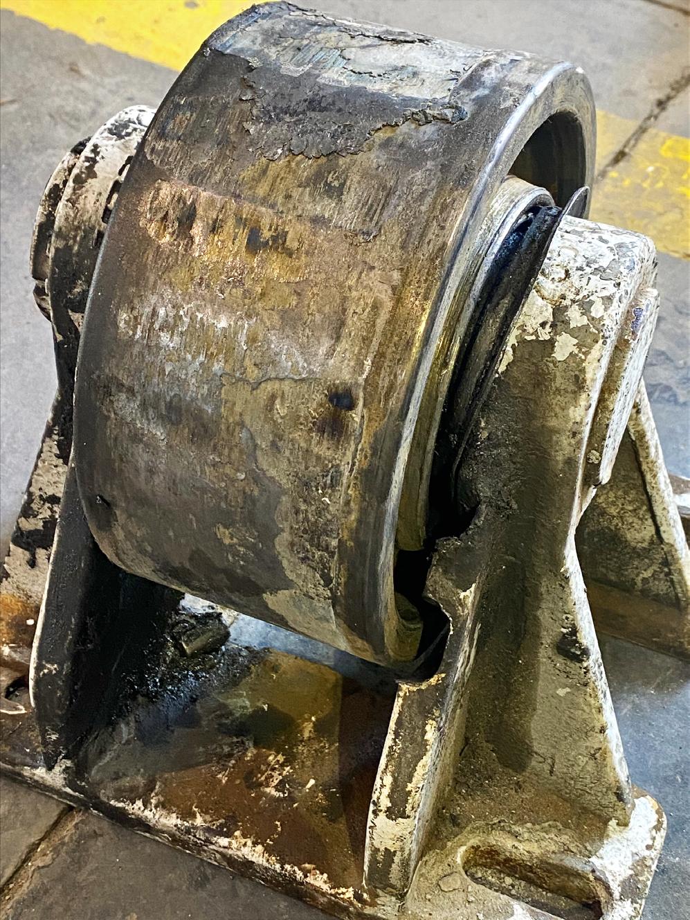
- Proper drum roller adjustment is critical for noise reduction & bearing life
- Rollers are to be greased weekly
- Use a quality EP#2 Lithium Grease
- Grease roller till you see a continual flow of CLEAN grease come OUT of seals
- Seals are installed backwards to allow grease to come OUT of roller & to keep contaminants OUT
- If drum roller noise is noticed, DO NOT grease roller track
- Spray water or WD-40 on roller & roller track
- If noise remains, most likely a bearing failure
- If noise goes away, then roller adjustment needs to be made
- If roller adjustment is needed, adjust as per below
- Align rollers with back edge of track
- Using straight edge or roller adjustment tool, “X” back edge of roller to drum track
- Using shims, shim roller to allow .010-.020” gap on front of roller between roller and track
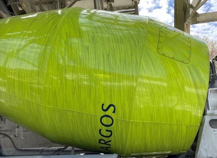
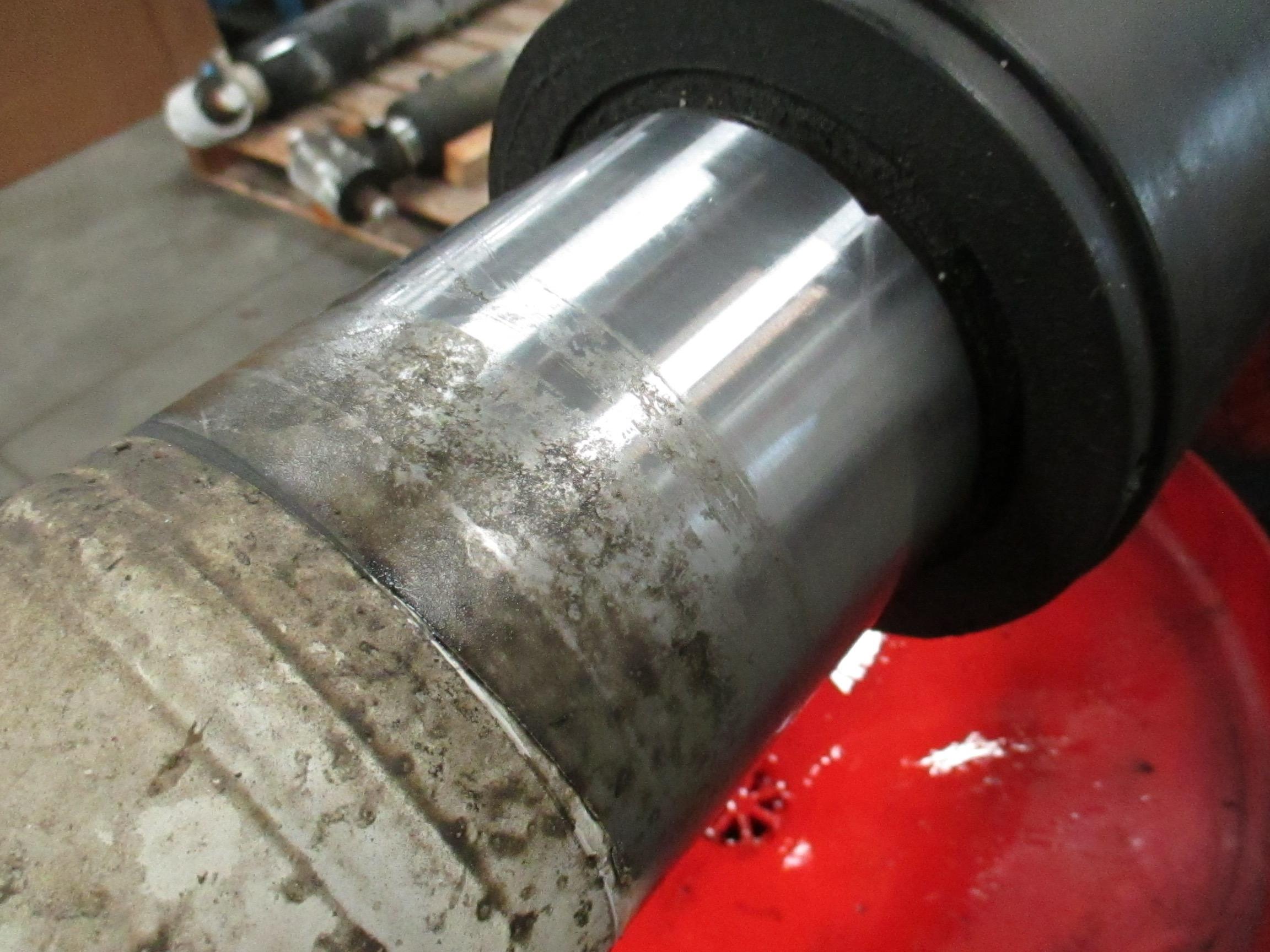
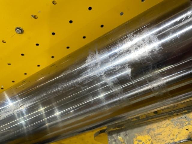
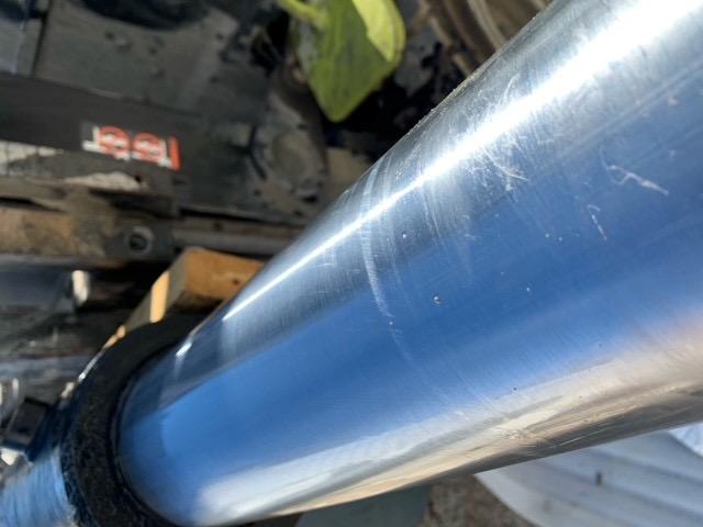
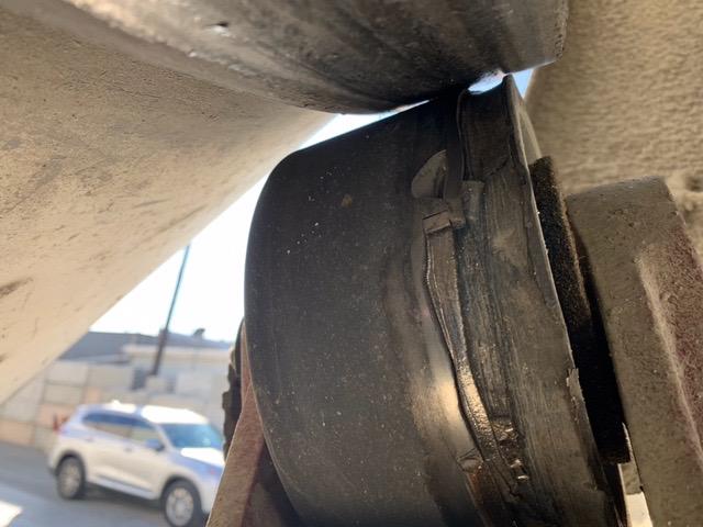
- Evidence of drum not rotating while in transit
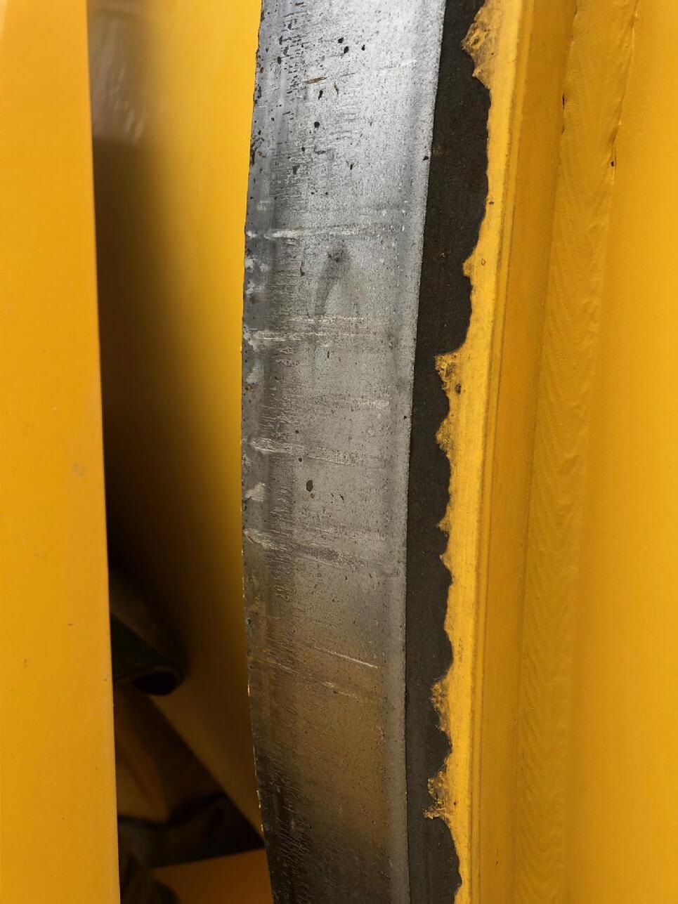
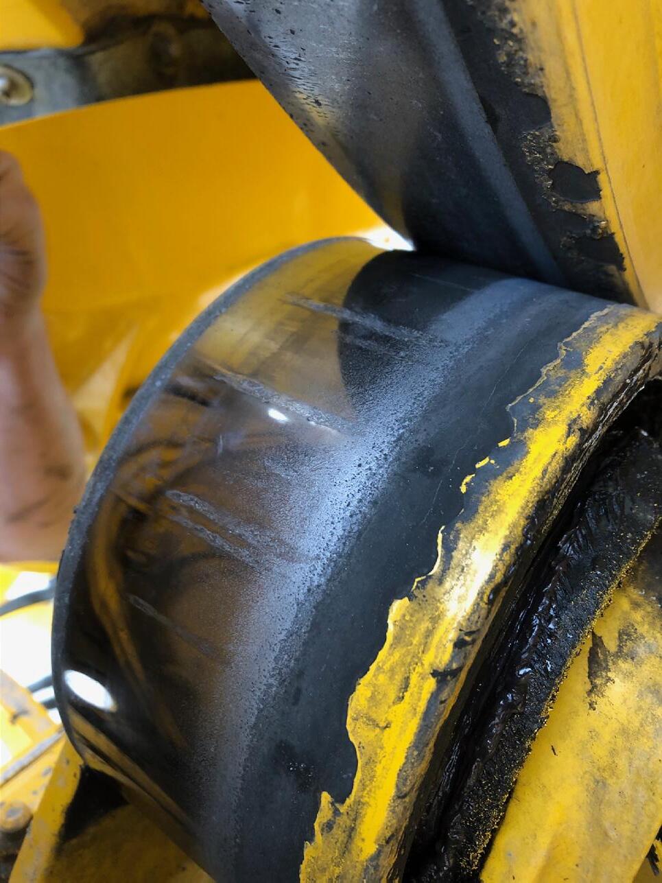
“Potter’s Wheel” Effect


- Recommended Lubricants
- Use a quality EP or lithium synthetic high temp grease
- Min. Timken Load of 50
- Meets NLGI Grade 2 specifications
- Operating range of -10’F - +325’F
- Inject grease till clean grease comes from all 4 caps on the u-joint
- For slip yoke, apply grease to zerk till grease appears at the pressure relief hole. Then cover hole with finger and apply grease till it appears and slip yoke seal
- DO NOT USE LUBRICANTS WITH MOLY ADDITIVES! will cause premature failure of u-joints.

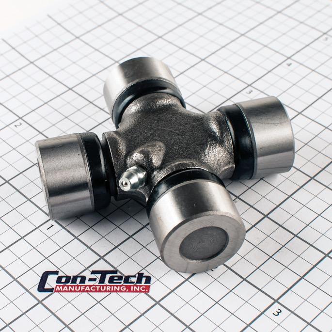

525’F Drip Point Timken EP Load 75

- U-joint inspections should be done every time a vehicle comes in for service
- Visually inspect for damaged bearing retainers & straps, strap bolts, companion flange bolts, damaged or dislodged snap rings
- Check input & output ends for looseness. Firmly grab drive shaft & try to move vertically/horizontally
- Check for presence of all grease zerk fittings. Damaged zerks should be replaced
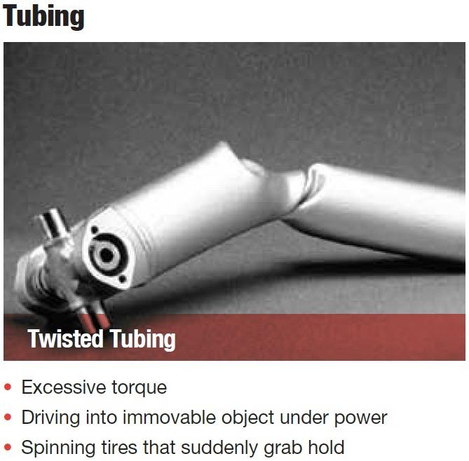
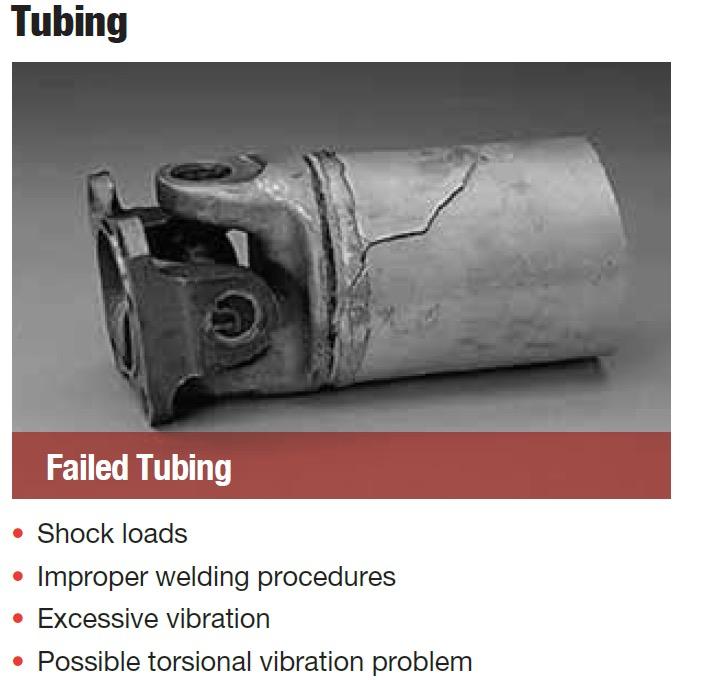
- Con-Tech utilizes a series 1350 u-joint
- 2.5” O.D. Tubing w .120” wall thickness