Craig Bahney, AIA, LEED AP BD+C Select Projects

craigbahney@gmail.com
402-730-4250
Craig Bahney, AIA, LEED BD+C
Projects:


Ssiger International Plaza
UCSF Pride Hall Ssiger International Plaza
Takshing House Lawndale
ReDefined
5 City Boulevard
CTF Finance Centre Suzhou New Gateway
China Life Financial Center
Roche Diagnostics St. Regis Belgrade
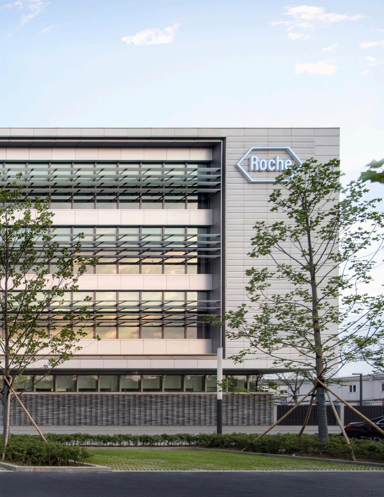
Roche Diagnostics Suzhou Campus

Suzhou, China
Manufacturing + Office (150,000 m2 GFA, Height: 25m) - Construction Completed
Owner: Roche Diagnostics
Lead Designer: Eric Keune, SOM Design Director
The design of the Roche pharmaceutical manufacturing campus creates a cohesive set of buildings inspired by local Suzhou gardens and Roche corporate principles. Building architecture consists of simple, understated volumes, utilizing a monochromatic color palette that reflects a quiet and elegant expression commonly found in Suzhou garden architecture and international Roche campuses. Sustainable features such as exterior solar shading, optimized window-to-wall ratio, high-performing glazing, and daylight optimization strategies led to LEED Platinum Certification for the Administration building.
Role Included:
• Lead Project Architect for Administration, QC, & Manufacturing buildings
• Generated campus master plan iterations in concept design
• Developed exterior wall design including Roman brick detail at exterior wall base, brick screen wall at the entrance building, and horizontal shading fin detail at QC and Administration buildings
• Led coordination of subconsultants and Local Architect of Record
Campus Entrance Building


Administration Building

Central Garden


Adminstration Building
Campus Aerial


 QC and Adminstration Building Courtyard
QC Building
QC and Adminstration Building Courtyard
QC Building


Canopy Detail Stair Detail


Administration Building Atrium
5 City Boulevard
Nashville, Tennessee
Office Tower (700,000 sf Construction GFA, Height: 240 ft) - Construction In Progress
Owner: Convexity Properties
Lead Designer: Paul DeSantis Goettsch Partners, Partner
5 City Boulevard is a office tower that acts as a business, retail, and wellness hub in Nashville’s One City development. The project provides access to high-end wellness amenities for tech sector tenants. The sweeping concave and convex curtain wall geometry carve terraces along the building’s east facade. Vertical fins on the curtain wall articulate the building form while providing passive solar shading. Outdoor restaurant seating, ample bike parking, and landscaped plazas and sidewalks activate the vibrant streetscape.
Role Included:
• Project Architect leading coordination meetings with civil, structural, and MEP subconsultants

• Developed Revit model including exterior wall, core, and parking garage

• Collaborated with trade partners to meet schedule and budget requirements within design-build project
• Reviewed contractor submittals and coordinated with trade partners in CA phase
Level 9 Plan
Level 13 Plan


L 01 0" L 02 20' - 0" 1.1 L 03 34' - 8" L 04 49' - 4" L 05 64' - 0" L 06 79' - 8" 2 3 4 5 6 7 8 9 PARKING L04 41' - 10" PARKING L05 52' - 9" PARKING L03 30' - 11" 1 5'-0" 27'-6" 30'-0" 30'-0" 30'-0" 30'-0" 30'-0" 27'-6" 37'-6" 15'-8" 14'-8" 14'-8" 14'-8" 20'-0" 3'-4" 11'-5" 10'-11" 10'-11" 10'-9" 3'-6" CONCRETE CRASH BARRIER -P1 FINISH @ EXPOSED EXTERIOR FACE -TYP G1G1G1G1G1G1G1 G1G1G1G1G1G1 G1 G1G1G1 G1G1G1G1G1G1G1G1 G1AG1AG1AG1AG1AG1AG1A G1A G1AG1AG1AG1AG1AG1A G1A G1 M3 M3 M3 G1 G1G1G1G1G1G1 M3 G1G1G1G1G1G1G1 G1G1G1G1G1G1 G1 G1AG1AG1AG1AG1AG1AG1A M3 M5M5M5M5M5M5M5M5M5M5M5M5M5 G1A G1AG1AG1AG1AG1AG1A G1G1G1 G1G1 M3 G1A G1A G1AG1A G1A G1AG1AG1AG1AG1AG1A G1AG1AG1A G1AG1AG1AG1AG1AG1AG1AG1A M3 G1G1G1G1G1G1 M3M3M3M3M3M3M3M3M3M3M3 M3 M3 M3M3M3M3 M3 M3 M3 M3 M3M3M3 M3M3 M3 M3 M3 M3 M3M3 M3M3M3M3M3M3 G4 G1A G1 M3 M3 M3 M3M3 G4G1G1G1G1G1 G4 G4 M3M3M3M3 M3 M3 G4G4G4G4G4 M3 M3M3M3M3M3 M3 M3 M3M3 G4G4 G4G4 G4 G4G4G4G4 G4 G5G5G5G5G5G5G5G5G5G5G5 G5 G5 G5 G5 G5 G5 G5 G4G4G4G4 G4 G4 G4 G4 G1 G1 G1 G1 G1 G1 G4G4 G4 G4G4 G4G4 G4G4G4G4 G1A G1A G1A M3M3M3M3 M3 M3 M3M3M3M3M3M3 M3 G1A G1A G1A M3 M3 M3 G1 G1 G1 G1A G1A G1A G1 G1 G1 M3M3M3M3M3M3M3 G1G1G1G1G1G1G1G1G1G1G1 G4A G1A G1A G1A G1 G1 G1 G1A G1A G1A G1 G1 G1 G1 G1 G1 G1AG1AG1A G5 G5 G5 G5 G5 G5 G5 G5 G5 G5 G5 G5 G5 M3 M3 M3 M3 G4A CONCRETE CRASH BARRIER -P1 FINISH @ EXPOSED EXTERIOR FACE -TYP G6G6G6 G6 G6 G4 G6 M3 G6 G6 G6 G6 M3 G6G6 G6G6 G6 G6 G6 M3M3M3 M3M3 M3 M1 M1 M1 G1 G1 G1A G1A M3 M3 G1 G1A G1 G1A M3 G1 G1A G1 G1A M3 M3 G4G4G4G4 G4A G5 G5 G5 G1 G1 G1 G1 M3M3M3 M3M3M3 M3M3M3 M3M3M3 M3M3M3 M3M3M3 G4 G4G4 G4 G4 G6 G6 G4 G4 G4 G4G4 G4 G4 G4G4 G4G4 G4 G4 G4G4G4G4G4G4 G4 M3 M3 M3 M3 G4A G4A M3 M2 M2 M2 M2 M2 M2 M2 M2 M2 M2 M2 M2 M2 M2 M3M3M3M3M3 M3 M5M5M5M5M5M5 M5M5M5M5M5M5 M5M5M5M5M5M5M5 M5M5M5M5M5M5M5 M5M5M5M5M5M5M5 G6 G6 G6 POTENTIAL 8'x8' BUILDING SIGNAGE M3 OPEN TO THROUGH WAY BEYOND PIN MOUNTED LED SIGNAGE PER SIGNAGE CONSULTANT G1AG1A M6 M3 A805.2 A805.1 6 +564.83 +565.96 +565.00 +564.08 +564.75 +564.25 +563.75 +563.00 +563.00 +563.00 9" S1 FINISH +564.00 T.O. CURB +564.25 4% 3 9% E LINE OF BUILDING ABOVE LINE OF BASEMENT BELOW 1.1 2 3 4 5 6 7 8 9 E 1 5'-0" 27'-6" 30'-0" 30'-0" 30'-0" 30'-0" 30'-0" 27'-6" 37'-6" D1 D1 D1 D1 D1 D1 D1 D1 D1 D1 1 -1 5 0-158 9'-6" 11'-4" 11'-4" 11'-4" 6'-6" 5'-0" EQ EQ 9'-10" SHEET TITLE: 224 Chicago, P gpchicago.com Architecture PROJECT NUMBER: NO: DATE: DESCRIPTION: COPYRIGHT 540 W MADISON CONVEXITY Structural Engineer: FOREFRONT Civil/Landscape Consultant: CSDG Parking Consultant: DESMAN KEY PLAN: 5 CITY BLVD. NASHVILLE, Elevator Consultant: H.H. ANGUS Mechanical-Plumbing-FP Design-Build: COMFORT GROUP/ICT Electrical Design-Build: WEIFIELD/ICT Interior Design Consultant: PARTNERS BY DESIGN Sustainability Consultant: SSRcx ENLARGED 21200 5 CITY OFFICE DEVELOPMENT 1/8" = 1'-0" EAST ELEVATION 3 DEFSTYPE FINISH DESCRIPTION METALTYPE FINISH DESCRIPTION FAÇADE FINISH 02/04/2022ISSUED 03/25/2022DESIGN 07/13/2022ISSUED 10/19/2022CD PROGRESS 12/09/2022BULLETIN DN UP UP L 01 0" L 02 20' - 0" L 03 34' - 8" L 04 49' - 4" L 05 64' - 0" L 06 79' - 8" B C D E PARKING L04 41' - 10" PARKING L05 52' - 9" PARKING L03 30' - 11" L01 MEZZANINE 12' - 3 1/2" A 61'-6" 45'-0" 30'-0" 45'-0" 15'-8" 14'-8" 14'-8" 14'-8" 20'-0" A801.1 8 OVERHEAD COILING DOOR -COLOR COAT TO MATCH M7 FINISH CONCRETE CRASH BARRIER -P1 FINISH @ EXPOSED EXTERIOR FACE -TYP 10'-11" 10'-11" 18'-7 1/2" G5G5G5G5G5 G5 G1AG1AG1AG1AG1AG1A G1A G1A G1A G1A G1A G1G1G1G1G1G1G1 G1 G1 G1A G5 G1 G1 G1 G1AG1AG1AG1AG1AG1AG1AG1AG1AG1A G1G1 G1A G1G1G1G1G1 G1AG1AG1AG1AG1A G1AG1A G1A G1G1G1G1G1 G1G1G1G1G1G1G1 G1 G1AG1AG1AG1AG1AG1AG1AG1AG1AG1AG1AG1A G1G1G1G1G1G1G1G1G1G1G1G1 G1AG1AG1AG1AG1AM2M2M2M2M2 G4 M2 G4G4G4 G4 G4 G1 G1 G1 G1 G1 G1A G1 G1A G1 G1A G1 G1A G1A G1 G1 G1AG1 G1 G1 G1 G1 G1 G1 G1 G1 G1 G1A G1A G1A G1A G1A G1A G1A G1A G1A G1A G1A G1A G1A G1A G1A G1A G1A G1A G1 G1 G1 G1 G1 G1 G1 G1 G1 G1A G1A G1A G1A G1A G1A G1A G1A G1A G1 G1 G1 G1 G1 G1 G1 G1 G1 G1AG1A G1A G1AG1A G1AG1AG1AG1A G2 G2 G2 G2 G2 G2 G2 G2 G2G2G2G2G2G2G2G2 M3 M3 M3 M2 G1 G1 G1 G1 G1 G1 G1 G1A G1A G1A G1A G1A G1A M2 M2 M2 M2 M2 M2 M2 M2 M2 G1A G1A G1A G1A G1A G1 G1 G1 G1 G1 G1 M3 G1 G1 G1 G1 G1 G1 G1AG1AG1AG1AG1A G1A M3 M3 M3 M3 M3 M3 M3 M3M3M3 M3 M3 M3 M3 M3 M3 M3 M3 M3 M3 M3 M3 M3 M3 M3 M3 M3M3 M3 M3 D2 D2D2 D2 D2 D2 D2 D2 D2 D2 D2 D2 G1A M2 M2 M2 M2 M2 M2 M2 M2 M2 G1A G1 G1A G1 G1A G1 M2 G4 M3 G1 G1G1 G1 G1 G1 G1A G1A G1A G1A G1A G1A G1A G1A G1A G1A G1A G1A G1A G1A G1A G1A G1A G1A G1A G1A G1A G1A G1A G1 G1 G1 G1 G1 G1 G1 G1 G1 G6G6 G6 G1 G1 G6 M3 G3 G3G3 M8M8M8 D2D2 D2 D2 M5 M5 M5 M5M5 M5 M5 M5 M5M5 M5 M5 M5 M5M5 M5 M5 M5 M5 M5 M5 M5 M5 M5 M5 M5 M5 M5 M5 M5 M5 M5 M5 M5 M5 M5 M5 M5M5 M5 M5 M5 M5 M5M5 M5 M5 M5 M5 M5M5 M3M3M3M3M3 M5 M5 M5 M5 M5 M5 M5 M5 M5 M5 M5 M5 M5 M5 M5 TEMPORARY INFILL A833 7 A804 9 A804 5 D2 D2 D2 D2 D2 D2 D2 D2 D2 D2 P1 HOLLOW METAL DOOR COLOR COAT TO MATCH M7 FINISH -TYP D2 D2 D2 D2 D2 D2 D2 D2 1.1 2 3 1 G RETAIL 01R1 TOILET RM 0108 STAIR 3 01ST3A SERVICE CORRIDOR 01C1 LOADING 0116 WATER ROOM 0121 GENERATOR 0123 PARKING ELEVATOR LOBBY P115 FIRE COMMAND 0103 5'-0" 27'-6" 30'-0" P-3P-2P-1 LINE OF BUILDING ABOVE LINE OF BUILDING ABOVE LINE OF BUILDING ABOVE LINE OF CANOPY ABOVE +563'.0" (0'-0") OVERHEAD ROLLING SHUTTER LINE OF BASEMENT BELOW LINE OF BASEMENT BELOW LOBBY 0101 PACKAGE 0110 L01 PARKING PL01 5-95/8 4 25-0 4 5-10 5-0 5-0 4-6 6-0 4-6 5-0 51 1 511 / 4 56 5 5-158 5-25/8 5-258 20-1034 5-258 5-25/8 4'-11" 5'-0" 4'-6" 6'-0" 4'-6" 5'-0" 5'-0" 1'-3 1/2" 07 35 2-0 34'-11" (7 EQ PANELS) 30-0 (7EQPANELS) 46-1118 (9EQPANELS) 1'-1" 3'-0"2'-1"5'-2"2'-1"3'-0" 1'-1" 4'-4" +563'.0" (0'-0") +563'.0" (0'-0") +563'.0" (0'-0") +563'.0" (0'-0") 563' 6" 10'-0" 24'-0" 28'-0" 24'-0" 8'-0" 10'-0" DOOR OPENER DOOR OPENER DOOR OPENER 1.1 2 3 1 G D1 D1 D1 3429 45'-0" 30'-0" 45'-0" 61'-6" 5'-0" 27'-6" 30'-0" D1 LED FIXTURE PER LIGHTING CONSULTANT - TYP LED FIXTURE PER LIGHTING CONSULTANT - TYP EXTERIOR SOFFIT 'D1' FINISH SYSTEM - TYP EXTERIOR SOFFIT 'D1' FINISH SYSTEM - TYP 5 A841.1 M8 ALUM. LOUVERSREF TO MEP DWGS 2'-10" 4'-8" 5'-0" 4'-0" 4'-0" 4'-0" 4'-0" 4'-0" 4'-0" 4'-0" 4'-0" 6" 3'-6" 4'-0" 4'-0" 4'-0" 4'-0" 4'-0" 4'-0" 4'-0" 4'-0" 4'-0" 4'-0" 4'-0" 4'-0" 3'-8" 3'-8" 2'-8" 3'-7" 12-31/2 15-0 11-2 5-0 2'-5" M8 ALUM. LOUVERSREF TO MEP DWGS D1 D1 D1 D1 D1 D1 D1 D1 D1 D1 D1 D1 D1 D1 D1 D1 D1 D1 D1 D1 D1 D1 D1 D1 4111/4 TYP TYP EQ-TYP EQ-TYP EQ TYPEQ -TYP T P EQ P Q SHEET TITLE: SHEET NUMBER: NO: Structural Engineer: FOREFRONT Civil/Landscape CSDG Parking Consultant: DESMAN KEY PLAN: Elevator Consultant: H.H. ANGUS Mechanical-Plumbing-FP COMFORT Electrical Design-Build: WEIFIELD/ICT Interior Design PARTNERS Sustainability SSRcx 12/9/2022 4:42:36 PM C:\Users\cbahney\Documents\21200_Convexity Lot 1_cbahney.rvt 21200 5 DEVELOPMENT 1/8" 1'-0" SOUTH ELEVATION 3 1/8" 1'-0" PLAN -LEVEL 01 1 ELASTOMERIC GLASSTYPE 1/8" 1'-0" RCP -LEVEL 01 2 02/04/2022ISSUED 03/25/2022DESIGN 07/13/2022ISSUED 10/19/2022CD 12/09/2022BULLETIN
Plan
Elevation
Site
East
South Elevation


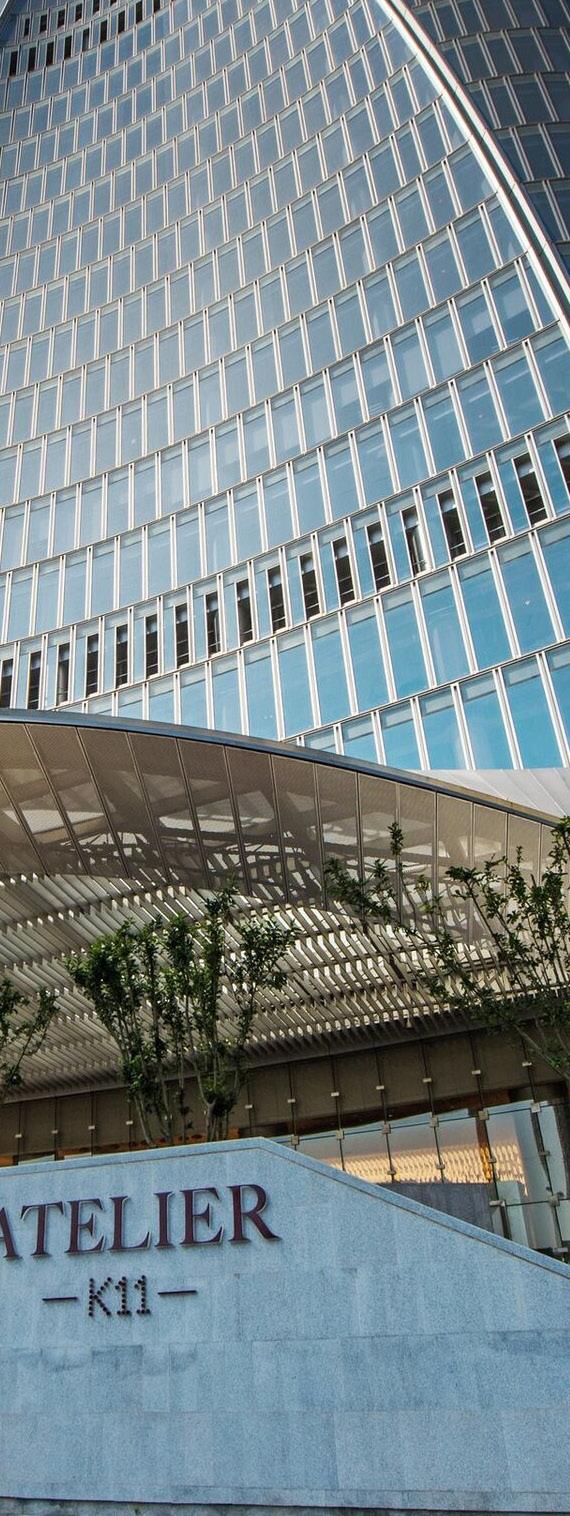
Tianjin Chow Tai Fook Finance Centre
Tianjin, China
Large Scale Mixed-Use (390,000 m2 GFA, Height: 530m) - Construction Completed
Owner: New World Development
Lead Designer: Brian Lee, SOM Partner
The 530-meter-tall CTF Finance Centre design utilizes concave and convex facade geometry to accommodate distinct programmatic elements and the structural requirements of a supertall tower in a high seismic zone. The resulting design forms a singular, bold expression on the Tianjin skyline. Eight sloping mega-columns increase the overall stiffness of the building’s perimeter frame, receive a large portion of the seismic forces, and eliminate the need for structural outriggers. This integrated multi-disciplinary approach to the design decreased material quantities and construction time compared to a conventional design. The podium building containing retail, cultural program, and hotel amenities creates a horizontal site registration with curved geometry reminiscent of the tower form. The screen wall diagrid creates a strong identity for K-11 branded retail. Cantilevered undulations in the screen wall form protective entrance canopies at retail entrances.
Role Included:
• Developed tower and podium design via 3D models and renderings
• Lead Project Architect for the retail podium building
• Detailed podium facade including podium diagrid screenwall, canopies, and entrances
• Reviewed exterior wall contractor submittals in CA phase


Program Stacking
Serviced Apartment Plan Hotel Plan Zone 1 Office Plan

Typical Exterior Wall

The insulated, V-shaped vertical mullions add character to the exterior wall and improve thermal energy performance. The crescent-shaped outer surface of the mullion captures daylight and creates a metal surface for the embedded LED to produce a dramatic nighttime lighting effect. Insulated Glass Units are flat in lieu of cold bent glass or the more expensive hot bent glass. An adapter was designed between the upper and lower transoms to accommodate the tower geometry and achieve flat glass.


 Typical Mullion Plan Detail
Detail Axon
Curtain wall Unit Adapter
LED
Flat
Typical Mullion Plan Detail
Detail Axon
Curtain wall Unit Adapter
LED
Flat
IGU


Podium Screen Wall Geometry

Retail Atrium


UCSF Pride Hall
Zuckerberg San Francisco General Hospital, San Francisco, CA
Research Laboratory (175,000 sf GFA, Height: 84 ft) – Construction Completed
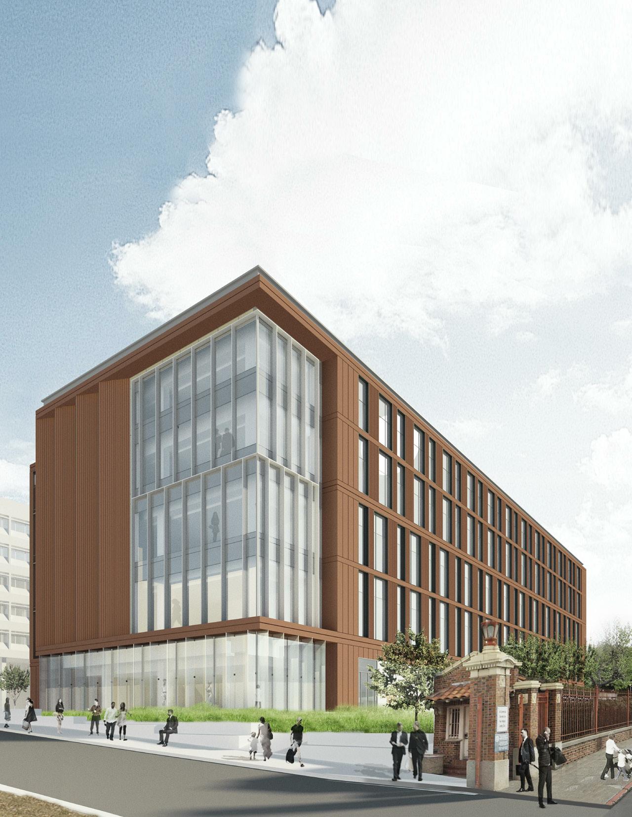
Owner: University of California, San Francisco
Lead Designer: Leo Chow, SOM Partner
Pride Hall on the Zuckerberg San Francisco General Hospital campus combines research, academic, and training functions into a highly functional and modern facility. Interior spaces, including bio-safety laboratories, vivariums, surgical training, and faculty workspace, are designed to promote wellness in the workplace while aligning with technical performance criteria provided by UCSF. Interconnecting stairs and town center meeting spaces activate the building’s front-facing, western elevation. The facade cadence of terracotta cladding and glazing is reminiscent of the scale and materiality of nearby historical General Hospital buildings.
Role Included:
• Developed interior architecture including Bio Safety Level-2 laboratories, vivarium, surgical, training facility, offices, and town hall meeting space
• Integrated ownership’s technical performance criteria into the architecture
• Collaborated with MEP and sustainability disciplines to meet LEED Silver standards
Level 5 Plan
Level 3 Plan
Ground Level Plan
01 02 03 04 05 06 07 08 09 10 11 12 13 14 15 16 17 E D C B A ENTRANCE HALL TOWN CENTER LARGE CONFERENCE LARGE CONFERENCE LARGE CONFERENCE CONFERENCE ROOM SIMULATION LAB STF SAW BONE LAB STF - SURGICAL TRAINING LAB FOCUS GROUP INT. EXAM EXAM INT. INT. INT. INT. EXAM INT. INT. INT. INT. CENTRAL SAMPLE STORAGE ELEC. BDF STORAGE VIVHOLDING VIV-LARGE PROCEDURE BIKE STORAGE UPS SERVER CATERING STORAGE INT. INT. INT. WAITING AREA ADULT TEAM WORKROOM EXAM PHLEBOTOMY PROCESSING LAB STF - DISSECTION BTF MTS WOKSTATIONS BTF - C-ARM WORKSPACE STFAUTOCLAVE CLEAN STORAGE VIV-SMALL HOLDING BTFSTORAGE MPOE VIV-SMALL HOLDING VIV-SMALL HOLDING VIV-SMALL PRCDR STORAGE VIV-SMALL PRCDR VIV-SMALL HOLDING VIV-SMALL PROCDR VIVTESTING VIVTESTING VIVTESTING VIVCAGE STAGING VIVAUTOCLAVE VIVIRRA VIVTESTING VIVHOUSING PLUMBING VIVSTORAGE VIVAIR LOCK VIVANIMAL WATER AIR LOCK SOIL CLEAN LACTATION TOILET WAITING AREACHILDREN FAC OFFICE/ BMS OFFICE VITAL SIGN STATION RECEPT. EQUIP. RES. KIT STO. STF.WOMEN’S LOCKER STF.MEN’S LOCKER SIM LAB ANTE-ROOM SIM LINEAR EQUIPMENT FAC SERVICES /SHOP STORAGE STF CTR BIKE SHOWERS MEN BIKE SHOWERS WOMEN FAC SERVICES CHANGE/ LOCKER VIV-CLEAN CAGE STAGING VIVGOWNING VIVWORK SPACE INF WASTE STOR. CUST. EQUIP JANITOR HUDDLE CONFERENCE MEDIUM TOWN CENTER HUDDLE ASSIGNABLE WORKSTATATIONS-TYP OFFICE OFFICE OFFICE OFFICE OFFICE OFFICE OFFICE HOTEL OFFICE HOTEL OFFICE CONFERENCE SMALL OFFICE OFFICE OFFICE ASSIGNABLE WORKSTATIONS-TYP ASSIGNABLE WORKSTATIONS-WET OFFICE OFFICE OFFICE HOTEL OFFICE CONFERENCE SMALL OFFICE OFFICE OFFICE HOTEL OFFICE ELEC STORAGE ASSIGNABLE WORKSTATIONS-TYP ASSIGNABLE WORKSTATIONS-WET OFFICE OFFICE HUDDLE OFFICE OFFICE ABSL3PROCEDURE ABSL3HOLDING BSL3PROCEDURE BSL3IMAGING BSL3PROCEDURE BSL3PROCEDURE BSL3PROCEDURE BSL3-LAB LINEAR EQUIPMENT EQUIPMENT TISSUE CULTURE ENVIR. ROOM FLEX TISSUE CULTURE FUME HOOD OPEN LAB AUTOCLAVE CLEAN BSL3 GOWNING AIR LOCK BSL3EQUIPMENT PLUMBING MICROSCOPY LINEAR EQUIPMENT TISSUE CULTURE TISSUE CULTURE EQUIPMENT EQUIP. OPEN LAB FLEX FLEX TISSUE CULTURE BSL2 OPEN LAB 01 02 03 04 05 06 07 08 09 10 11 12 13 14 15 16 17 E D C B A TISSUE CULTURE EQUIP. FLEX MECH. SHAFT BSL2 TISSUE CULTURE BSL2 TISSUE CULTURE BSL2 EQUIP. ALCOVE BSL2 EQUIP. BSL2 AUTOCLAVE BSL2 EQUIP. ASSIGNABLE WORKSTATATIONS-WET TISSUE CULTURE FUME HOOD TISSUE CULTURE LINEAR EQUIPMENT LINEAR EQUIPMENT SERVICE CENTER BSL2 GOWNING OPEN LAB LINEAR EQUIPMENT TISSUE CULTURE STERILE STORAGE FUME HOOD STERIL. ALCOVE LINEAR EQUIPMENT MECH. SHAFT SERVICE CENTER HOTEL WORKSTATIONS 01 02 03 04 05 06 07 08 09 10 11 12 13 14 15 16 17 E D C B A OFFICE OFFICE OFFICE HOTEL OFFICE SERVICE CENTER CONFERENCE SMALL OFFICE OFFICE OFFICE HOTEL OFFICE OFFICE OFFICE OFFICE OFFICE OFFICE HOTEL OFFICE ASSIGNABLE WORKSTATIONS-TYP. HOTEL OFFICE OFFICE OFFICE OFFICE OFFICE OFFICE OFFICE HOTEL OFFICE ASSIGNABLE WORKSTATIONS-TYP. OFF. HUDDLE HUDDLE CONFERENCE MEDIUM HUDDLE HUDDLE OFF. OFF. OFF. OFF. STORAGE ELEC CPF OFFICE OFFICE OFFICE HOTEL OFFICE OFFICE OFFICE OFFICE HOTEL OFFICE ASSIGNABLE WORKSTATIONS-TYP. OFF. OFF. OFF. OFF. OFF. OFFICE OFFICE OFFICE HOTEL OFFICE OFFICE OFFICE OFFICE HOTEL OFFICE ASSIGNABLE WORKSTATIONS -TYP. CONFERENCE MEDIUM HUDDLE HUDDLE OFFICE OFFICE OFFICE OFFICE OFFICE OFFICE OFFICE OFFICE ASSIGNABLE WORKSTATIONS-TYP. TOWN CENTER HUDDLE CONFERENCE MEDIUM HOTEL OFFICE HOTEL OFFICE HOTEL OFFICE HOTEL OFFICE OFFICE OFFICE OFFICE OFFICE OFFICE OFFICE OFFICE OFFICE ASSIGNABLE WORKSTATIONS-TYP. OFFICE OFFICE OFFICE OFFICE ASSIGNABLE WORKSTATIONS-TYP. OFFICE OFFICE OFFICE OFFICE OFFICE OFFICE OFFICE OFFICE OFFICE OFFICE ASSIGNABLE WORKSTATIONS-TYP. HOTEL OFFICE HOTEL OFFICE OFFICE LACTATION STOR. ASSIGNABLE WORKSTATIONS-TYP. HOTEL OFFICE HOTEL OFFICE HOTEL OFFICE HOTEL OFFICE MECH. SHAFT STOR. CPF

 Town Hall
West Elevation
Town Hall
West Elevation
EGRESS STAIR 1 -TRANSVERSE SECTION 11
ZSFG SCALE: 1/4" = 1'-0"
EGRESS STAIR 1 -LONGITUDINAL SECTION 1
SCALE: 1/4" = 1'-0"
SCALE: 1/4" = 1'-0"
ZSFG 3079
ZSFG 3079
STAIR SECTIONS 218024
STAIR SECTIONS DETAILS 218024
DETAILS 218024
DN UP DN STEEL HANGER ROD TYP. GUARDRAIL ASSEMBLY, TYP STL PIPE HANDRAIL, PTD LED LIGHTING SEALED CONCRETE FILL OVER LANDING AND STAIR TREADS 19 A-5203 STL LANDING SUPPORT, PTD STAIR NOSING RE: PLAN G U A R D R A H E G H T 3'-6 1/2" 3'-0" T.O. HANDRAIL 3' 6 1/2" T.O. GUARDRAIL LANDING RE: SECTION NON-SHRINK GROUT CONTRASTING STRIPE AT APPROACH AND LOWER TREAD 2"1" 1 1/2" OD STL PIPE HANDRAIL MTL-4, PERFORATED METAL PANEL STEEL GUARDRAIL POST STEEL PLATE STRINGER, PTD PROJECTION 3 1/2" HANDRAIL PROJECTION 3 1/2" HANDRAIL 1/4" x 8" LONG FORMED STEEL PLATE STEEL GUARDRAIL POST SCHEDULE RE: PARTITION 1 1/2" 02 CONCRETE FILLED LANDING STEEL HANGER ROD TYP., GUARDRAIL ASSEMBLY, TYP STL PIPE HANDRAIL, PTD. CL 1'-0 1/2" STEEL HANGER ROD, TYP. REFER TO ENLARGED PLANS FOR PARTITION TYPE 1'-0" TREAD WIDTH 11" HANDRAIL EXTENSION 1'-11" 4" RE: PLAN RE: PLAN PROJECTION 3 1/2" HANDRAIL 3 1/2" 3 1/2" 1'-3" RE: PLAN RE: PLAN 3 1/2" 3 1/2" STL LANDING SUPPORT, PTD STL LANDING SUPPORT, PTD 18 A-5203 1 1/2" RE: PLAN PTD STRINGE, TYP. GUARDRAIL ASSEMBLY, TYP. NON-SHRINK GROUT CONTRASTING STRIPE AT APPROACH AND LOWER TREAD 02 STEEL LATE STRINGER, PTD. STL PIPE HANDRAIL,PTD. GUARDRAIL ASSEMBLY EDGE OF SLAB REFER TO ENLARGED PLANS FOR PARTITION TYPE HANDRAIL EXTENSION 1'-0" RE: PLAN STAIR WIDTH PROJECTION, TYP 3 1/2" HANDRAIL NON-SHRINK GROUT CONTRASTING STRIPE AT APPROACH AND LOWER TREAD CONTRACTOR THE BOLDT 375 BEALE SAN FRANCISCO, ARCHITECT SKIDMORE, ONE MARITIME SAN FRANCISCO, CIVIL FREYER 150 EXECUTIVE SAN FRANCISCO, STRUCTURAL DEGENKOLB 375 BEALE SAN FRANCISCO, MECHANICAL TAYLOR 1080 MARINA ALAMEDA, PLUMBING SOUTHLAND 33225 WESTERN UNION CITY, ELECTRICAL SILVERMAN 1201 PARK EMERYVILLE, LAB PLANNER JACOBS 401 B STREET, SAN DIEGO, LANDSCAPE MANTLE 930 CARLTON BERKELEY, UCSF AND BUILDING 1001 SAN SCALE: 1 1/2" = 1'-0" EGRESS STAIR 1 LEVEL 1-3 INTERMEDIATE LANDING SECTION 18 SCALE: 1 1/2" = 1'-0" EGRESS STAIR 1 TRANSVERSE SECTION 19 SCALE: 1 1/2" = 1'-0" EGRESS STAIR 1 -LEVEL 05 TOP LANDING PLAN 04 NO.DESCRIPTION CONSTRUCTION CONSTRUCTION 1BACKCHECK 1 1 1 STEEL HANGER ROD TYP. GUARDRAIL ASSEMBLY, TYP STL PIPE HANDRAIL, PTD LED LIGHTING SEALED CONCRETE FILL OVER LANDING AND STAIR TREADS 19 A-5203 STL LANDING SUPPORT, PTD STAIR NOSING RE: PLAN G U A R D R A H E G H T 3'-6 1/2" 3'-0" T.O. HANDRAIL 3' 6 1/2" T.O. GUARDRAIL LANDING RE: SECTION NON-SHRINK GROUT CONTRASTING STRIPE AT APPROACH AND LOWER TREAD 2"1" MTL-4, PERFORATED METAL PANEL 2" X 2" STEEL TUBE PTD. STL PIPE HANDRAIL, PTD. CONCRETE FILLED METAL PAN T.O. HA NDRAIL 3'-0" 2" x 2" STEEL GUARDRAIL POST, TYP. RE: SE CTION RISER 1/2"MAX STRINGER PLATE, PTD CONT. L ANGLE BTWN STRINGERS RE: PLAN TREAD WIDTH STAIR NOSING 1'-0" TREAD WIDTH 11" HANDRAIL EXTENSION 1'-11" T.O. HA NDRAIL 3'-6 1/2" T.O. HA NDRAIL 3'-0" 2'-3" MAX. EMBED SLEEVE NON-SHRINK GROUT CONTRASTING STRIPE AT APPROACH AND LOWER TREAD 1"2" 1 1/2" OD STL PIPE HANDRAIL MTL-4, PERFORATED METAL PANEL STEEL GUARDRAIL POST STEEL PLATE STRINGER, PTD PROJECTION 3 1/2" HANDRAIL PROJECTION 3 1/2" HANDRAIL 1/4" x 8" LONG FORMED STEEL PLATE STEEL GUARDRAIL POST SCHEDULE RE: PARTITION 1 1/2" STEEL HANGER RE: PLAN 3 1/2" STL PTD PTD GUARDRAIL NON-SHRINK GROUT CONTRASTING STRIPE AT APPROACH AND LOWER TREAD 3/28/2020 7:49:21 PM SCALE: 1 1/2" = 1'-0" EGRESS STAIR 1 LEVEL 1-3 INTERMEDIATE LANDING SECTION 18 SCALE: 1 1/2" = 1'-0" SECTION @ EGRESS STAIR BOTTOM LANDING 16 SCALE: 1 1/2" = 1'-0" EGRESS STAIR 1 TRANSVERSE SECTION 19 1 1 LEVEL 01 +79' -0" ROOF LEVEL +157' -4" LEVEL 05 +143' -2" LEVEL 04 +129' -0" LEVEL 03 +112' -4" LEVEL 02 +95' -8" LANDING 87'-4" LANDING 104'-0" LANDING 120'-8" LANDING 135'-9 7/8" 78'-4" 14'-2" 14'-2" 16'-8" 16'-8" 16'-8" 7'-4 1/8" 6'-9 7/8" 8'-4" 8'-4" 8'-4" 8'-4" 8'-4" 8'-4" TO PARAPET +162' -10" LEVEL 01 -0" LEVEL -4" LEVEL 05 -2" LEVEL 04 -0" LEVEL 03 -4" LEVEL 02 -8" LANDING 5/16" LANDING 104'-0" LANDING 120'-8" LANDING 136'-1" LANDING 148'-1 1/8" PARAPET -10" LEVEL 01 +79' -0" ROOF LEVEL +157' -4" LEVEL 05 +143' -2" LEVEL 04 +129' -0" LEVEL 03 +112' -4" LEVEL 02 +95' -8" LANDING 87'-4" LANDING 104'-0" LANDING 120'-8" LANDING 135'-9 7/8" 78'-4" 14'-2" 14'-2" 16'-8" 16'-8" 16'-8" 14 RISERS AT 6.30" = 7'-4 1/8" 13 RISERS AT 6.30" = 6'-9 7/8" 15 RISERS AT 6.67" = 8'-4" 15 RISERS AT 6.67" = 8'-4" 15 RISERS AT 6.67" = 8'-4" 15 RISERS AT 6.67" = 8'-4" 15 RISERS AT 6.67" = 8'-4" 15 RISERS AT 6.67" = 8'-4" 6'-8" CLR TO PARAPET +162' -10" 16 A-5203 18 A-5203 MTL-4 GUARDRAIL, TYP. 4'-3 1/2"5'-3" 5'-3" 5'-3" 5'-3" SEAL & SIGNATURE CAMPUS SHEET NUMBER SHEET NAME PROJECT NUMBER UCSF PROJECT STRUCTURAL DEGENKOLB 375 BEALE STREET, SUITE 500 SAN FRANCISCO, CA 94105 MECHANICAL TAYLOR ENGINEERING 1080 MARINA VILLAGE PARKWAY, SUITE ALAMEDA, CA 94501 PLUMBING SOUTHLAND INDUSTRIES 33225 WESTERN AVENUE UNION CITY, CA 94587 ELECTRICAL SILVERMAN & LIGHT 1201 PARK AVENUE, SUITE 100 EMERYVILLE, CA 94608 LAB PLANNER JACOBS CONSULTANCY 401 B STREET, SUITE 1560 SAN DIEGO, CA 92101 LANDSCAPE ARCHITECT MANTLE 930 CARLTON STREET, 2ND FLOOR BERKELEY, CA 94710 KEYPLAN
A-5201 DETAILS
NO.DESCRIPTION CONSTRUCTION DOCUMENTS2020.01.13 CONSTRUCTION DOCUMENTS2020.02.24 1BACKCHECK 1 1 1 1 1 1 1 LEVEL 01 +79' -0" ROOF LEVEL +157' -4" LEVEL 05 +143' -2" LEVEL 04 +129' -0" LEVEL 03 +112' -4" LEVEL 02 +95' -8" LANDING 87'-4" LANDING 104'-0" LANDING 120'-8" LANDING 135'-9 7/8" 78'-4" 14'-2" 14'-2" 16'-8" 16'-8" 16'-8" 7'-4 1/8" 6'-9 7/8" 8'-4" 8'-4" 8'-4" 8'-4" 8'-4" 8'-4" TO PARAPET +162' -10" LEVEL 01 +79' -0" ROOF LEVEL +157' -4" LEVEL 05 +143' -2" LEVEL 04 +129' -0" LEVEL 03 +112' -4" LEVEL 02 +95' -8" LANDING 87'-4" LANDING 104'-0" LANDING 120'-8" LANDING 135'-9 7/8" 78'-4" 14'-2" 14'-2" 16'-8" 16'-8" 16'-8" 14 RISERS AT 6.30" = 7'-4 1/8" 13 RISERS AT 6.30" = 6'-9 7/8" 15 RISERS AT 6.67" = 8'-4" 15 RISERS AT 6.67" = 8'-4" 15 RISERS AT 6.67" = 8'-4" 15 RISERS AT 6.67" = 8'-4" 15 RISERS AT 6.67" = 8'-4" 15 RISERS AT 6.67" = 8'-4" 6'-8" CLR TO PARAPET +162' -10" 16 A-5203 18 A-5203 MTL-4 GUARDRAIL, TYP. 4'-3 1/2"5'-3" 5'-3" 5'-3" 5'-3" SEAL & SIGNATURE CAMPUS SHEET NUMBER SHEET NAME PROJECT NUMBER UCSF PROJECT NUMBER 150 EXECUTIVE PARK BLVD., SUITE 4200 SAN FRANCISCO, CA 94134 STRUCTURAL DEGENKOLB 375 BEALE STREET, SUITE 500 SAN FRANCISCO, CA 94105 MECHANICAL TAYLOR ENGINEERING 1080 MARINA VILLAGE PARKWAY, SUITE 501 ALAMEDA, CA 94501 PLUMBING SOUTHLAND INDUSTRIES 33225 WESTERN AVENUE UNION CITY, CA 94587 ELECTRICAL SILVERMAN & LIGHT 1201 PARK AVENUE, SUITE 100 EMERYVILLE, CA 94608 LAB PLANNER JACOBS CONSULTANCY 401 B STREET, SUITE 1560 SAN DIEGO, CA 92101 LANDSCAPE ARCHITECT MANTLE 930 CARLTON STREET, 2ND FLOOR BERKELEY, CA 94710 KEYPLAN NORTH
STAIR
PRJ-034 SCALE: 1/4" = 1'-0"
A-5201
SECTIONS
EGRESS STAIR 1 -TRANSVERSE SECTION 11
NO.DESCRIPTION DATE CONSTRUCTION DOCUMENTS2020.01.13 CONSTRUCTION DOCUMENTS2020.02.24 1BACKCHECK 1 2020.03.27 1 1 1 1 1 1 LEVEL 01 +79' -0" ROOF LEVEL +157' -4" LEVEL 05 +143' -2" LEVEL 04 +129' -0" LEVEL 03 +112' -4" LEVEL 02 +95' -8" LANDING 87'-4" LANDING 104'-0" LANDING 120'-8" LANDING 135'-9 7/8" 78'-4" 14'-2" 14'-2" 16'-8" 16'-8" 16'-8" 7'-4 1/8" 6'-9 7/8" 8'-4" 8'-4" 8'-4" 8'-4" 8'-4" 8'-4" TO PARAPET +162' -10" LEVEL 01 +79' -0" ROOF LEVEL +157' -4" LEVEL 05 +143' -2" LEVEL 04 +129' -0" LEVEL 03 +112' -4" LEVEL 02 +95' -8" LANDING 87'-4" LANDING 104'-0" LANDING 120'-8" LANDING 135'-9 7/8" 78'-4" 14'-2" 14'-2" 16'-8" 16'-8" 16'-8" 14 RISERS AT 6.30" = 7'-4 1/8" 13 RISERS AT 6.30" = 6'-9 7/8" 15 RISERS AT 6.67" = 8'-4" 15 RISERS AT 6.67" = 8'-4" 15 RISERS AT 6.67" = 8'-4" 15 RISERS AT 6.67" = 8'-4" 15 RISERS AT 6.67" = 8'-4" 15 RISERS AT 6.67" = 8'-4" 6'-8" CLR TO PARAPET +162' -10" 16 A-5203 18 A-5203 MTL-4 GUARDRAIL, TYP. 4'-3 1/2"5'-3" 5'-3" 5'-3" 5'-3" SEAL & SIGNATURE CAMPUS CAAN SHEET NUMBER SHEET NAME PROJECT NUMBER UCSF PROJECT NUMBER 150 EXECUTIVE PARK BLVD., SUITE 4200 SAN FRANCISCO, CA 94134 STRUCTURAL DEGENKOLB 375 BEALE STREET, SUITE 500 SAN FRANCISCO, CA 94105 MECHANICAL TAYLOR ENGINEERING 1080 MARINA VILLAGE PARKWAY, SUITE 501 ALAMEDA, CA 94501 PLUMBING SOUTHLAND INDUSTRIES 33225 WESTERN AVENUE UNION CITY, CA 94587 ELECTRICAL SILVERMAN & LIGHT 1201 PARK AVENUE, SUITE 100 EMERYVILLE, CA 94608 LAB PLANNER JACOBS CONSULTANCY 401 B STREET, SUITE 1560 SAN DIEGO, CA 92101 LANDSCAPE ARCHITECT MANTLE 930 CARLTON STREET, 2ND FLOOR BERKELEY, CA 94710 KEYPLAN NORTH
PRJ-034 SCALE: 1/4" = 1'-0"
STAIR 1
SECTION 11 SCALE: 1/4" = 1'-0"
STAIR
SECTION
NO.DESCRIPTION DATE CONSTRUCTION DOCUMENTS2020.01.13 CONSTRUCTION DOCUMENTS2020.02.24 1BACKCHECK 1 2020.03.27 1 1 1 1 1 1
EGRESS STAIR 1 -LONGITUDINAL SECTION 1
A-5201
EGRESS
-TRANSVERSE
EGRESS
1 -LONGITUDINAL
1
INVEST South/West: Lawndale ReDefined Chicago, IL
Mixed-Use (91,000 sf GFA, Height: 60 feet) – Winning RFP Entry Owner: GRE Ventures, Imagine Group, 548 Capital
Lawndale Redefined improves the urban quality of life for families and residents of all ages, making the city more convenient, walkable, and fun. The project envisions the following: a flexible, community-oriented space where people can shop, work, dine, connect with neighbors, showcase art, grow a business, and celebrate North Lawndale’s proud history and confident steps into its next chapter. The proposed on-site unit mix includes 48 affordable rental apartments, 12 market-rate units, three townhouse units, a community incubator and tech center, retail, grocery, two restaurants, and an outdoor connecting plaza.
Two strategic venues set this mixed-use residential development apart and give the community highly versatile assets for directing their economic and social future – the multi-functional technology-focused community center (the CUBE: Center for Urban Brainstorming and Education) and the broad public open space (the Square). They can change according to the community’s many purposes: workforce skills training and entrepreneurial incubator, tutoring and mentoring, common ground for organizing, entertainment and seasonal markets, arts spaces, and quiet places.
Role Included:
• Developed project programatic masterplan including affordable housing, community center, retail, and grocery store

• Designed, modeled, and produced 3D visualization for the CUBE building, a technology and arts-focused community center
• Produced competition deliverables including renderings, animations, and diagrams


 The CUBE: Art Fair Configuration
The CUBE: Tech Center Configuration
The CUBE: Art Fair Configuration
The CUBE: Tech Center Configuration


St. Regis Belgrade and The Residences at St. Regis Belgrade
Belgrade, Serbia
Hotel and Residential Tower (47,500 m2 GFA, Height: 168m) - Construction In Progress
Owner: Belgrade Waterfront / Eagle Hills
Lead Designer: Brian Lee, SOM Partner

The 42-story hotel and residential tower with an adjoining civic plaza are the centerpiece of the Sava Riverfront redevelopment. Structural and functional rationale informs the dynamic form of the tower. Upper floors containing residential units are rotated 90 degrees from the hotel at the lower portion of the tower. The structural logic is of a broad wind sail for the building’s upper floors, which can efficiently use the depth of the lower floors to resist wind loads, using the structural principle: ‘large wind sail, large structure, and small wind sail, small structure’. The fluidic expression shaping the enclosure recalls the flow of the Sava River. The transformation of building geometry from ground to top also optimizes riverfront views from hotel rooms and residential units. Siting the tower on the site’s south end provides ample space for a new public plaza with connectivity to the riverfront promenade and the surrounding neighborhood.
Role Included:
• Lead Project Architect and point of contact with project ownership
• Led interdisciplinary coordination with subconsultants and Local Architect of Record
• Delegated design and technical assignments to project team members
• Implemented sustainable strategies, including bird protection glass, high-performance envelope, and river water cooling system
Volume Program Optimized Views Efficient Structure Transition Fluid Form 168 Meters Deep Structure Hotel Residential/Amenity Narrow Stance Wide Stance

LEVEL B1M -4.27 m LEVEL B1 -7.87 m LEVEL 02 6.60 m LEVEL 03 12.45 m LEVEL 04 15.90 m LEVEL 05 19.35 m LEVEL 06 22.80 m LEVEL 07 26.25 m LEVEL 08 29.70 m LEVEL 09 33.15 m LEVEL 10 36.60 m LEVEL 11 40.05 m LEVEL 12 45.30 m LEVEL 14 52.20 m LEVEL 15 56.10 m LEVEL 16 60.00 m LEVEL 17 63.90 m LEVEL 18 67.80 m LEVEL 19 71.55 m LEVEL 20 76.50 m LEVEL 21 79.95 m LEVEL 22 83.40 m LEVEL 23 86.85 m LEVEL 24 90.30 m LEVEL 25 93.75 m LEVEL 26 97.20 m LEVEL 27 100.65 m LEVEL 28 104.10 m LEVEL 29 107.55 m LEVEL 30 111.00 m LEVEL 31 114.45 m LEVEL 32 117.90 m LEVEL 33 121.35 m LEVEL 34 124.80 m LEVEL 35 128.25 m LEVEL 40 148.20 m LEVEL 41 154.80 m LEVEL 37 135.45 m LEVEL 36 131.70 m T/TOWER 168.00 m LEVEL 38 139.20 m LEVEL 39 142.95 m GROUND LEVEL 0.00 m SURROUNDING GRADE -0.32 m LEVEL B1 (MEP) -9.47 m 660 0 660 0 660 0 525 0 375 0 375 0 375 0 16 L E V E L S @ 3450 = 5520 0 495 0 375 0 390 0 390 0 390 0 390 0 690 0 525 0 8 LEVELS @ 3450 = 2760 0 585 0 275 0 385 0 32 0 395 0 360 0 160 0 ROOF 161.40 m MEP GROUND LEVEL MEZZ 3.85 m BSERVATION ESTAURANT MEP SIGNATURE ESIDENTIAL HOTEL ROOF/MEP KULA ESIDENTIAL SKY COLLECTION 1 : 300 SECTION 2 Observation Duplex Residential Hotel Hotel Lobby And Amenities MEP Restaurant MEP MEP/Parking Residential T.O. Crown +168.00M Section


Residential Unit
Observation Deck
Duplex
 Construction Photo


Residential and Hotel Entrances


 Riverfront Promenade
Civic Plaza
Riverfront Promenade
Civic Plaza

Site Plan
China Life Financial Center
CBD Parcel Z-13, Beijing, China
Office Tower (119,000 m2 GFA, Height: 189m) - Construction
Owner: Sino-Ocean Group
Lead Designer: Brian Lee, SOM Partner
Completed
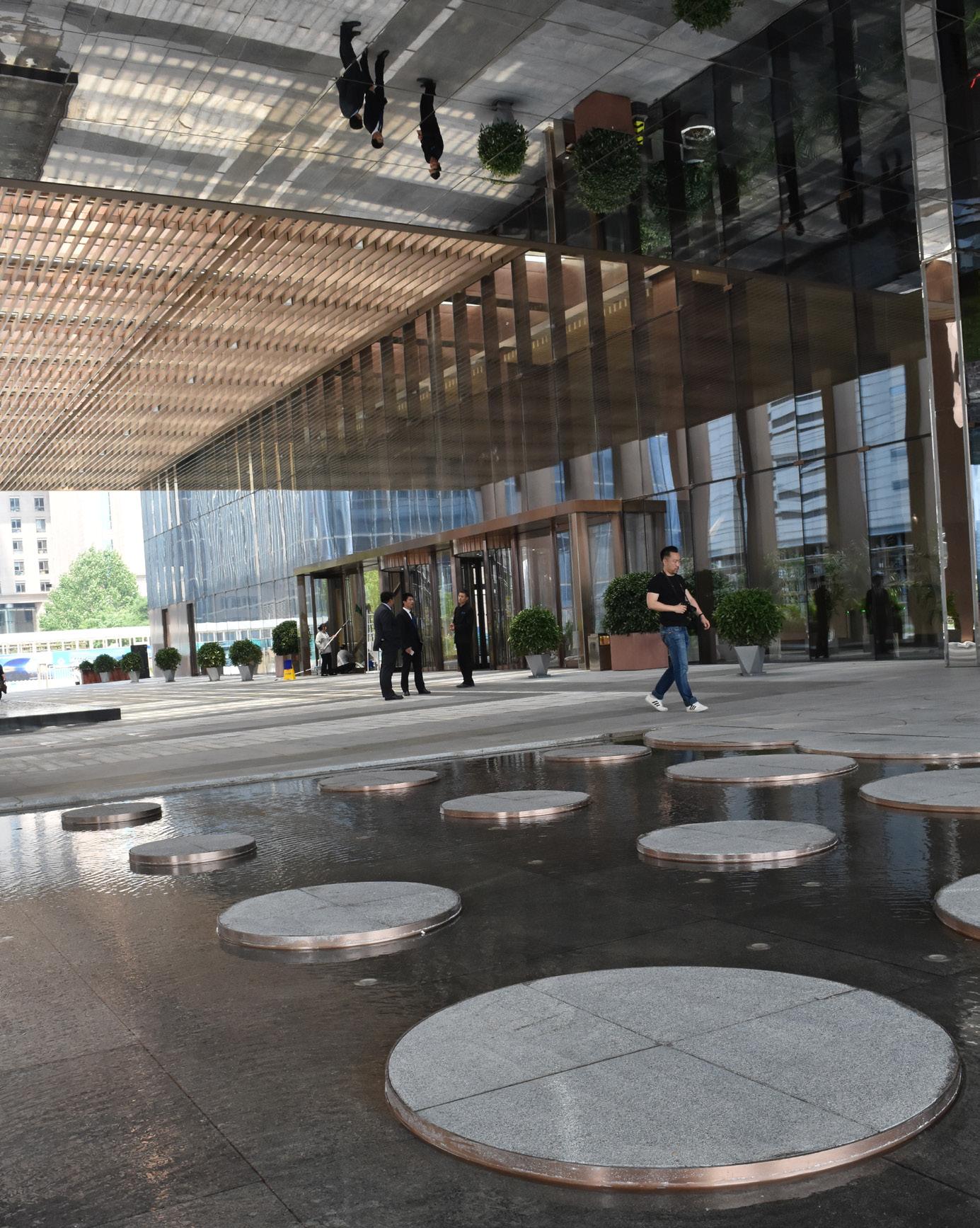
Technical innovation and occupant wellness are guiding design principles for the LEED Gold and WELL Gold certified China Life Financial Center. Cantilevered 9-meter end bays create column-free, unobstructed views to the north and south. The east and west tower facades feature an internally ventilated cavity wall with automated blinds. Perforated stainless steel panels on the façade allow natural ventilation into interior spaces through operable, insulated panels. These sustainable features improve the overall energy performance of the building and thermal comfort for the office occupants. LED lighting within the cavity wall animates the facade during holidays and special occasions. A glass and steel trellis at ground level provides shading and a dramatic arrival experience above a multipurpose entrance court. A network of ground and basement pedestrian connections are integrated into the site design to connect to the subway and neighboring buildings in the Central Business District.
Role Included:
• Project team leader: delegated design and technical assignments to team members
• Designed architectural ground plane including drop off court, subway connections, lobby, retail space
• Detailed internally ventilated cavity facade that improves occupant thermal comfort while reducing heating and cooling loads
• Collaborated with MEP and sustainability disciplines to meet LEED Gold standards and WELL certification
• Coordinated with structural discipline to achieve 9m cantilevered, column-free end bays of each floor
• Reviewed exterior wall submittal review and performed site observation CA phase
Typical Plan


 Section Through Cavity Wall
Section Through Operable Panel
Section Through Cavity Wall
Section Through Operable Panel
Wall Typical Elevation
Ventilation
Plan Detail
Cavity
Operable
Panel
Internally Ventilated Cavity Wall


 Operable Ventilation Panel
Site Plan West Lobby Retail Bay 1
Pool East Lobby Retail Bay 2 Entrance Court
Laneway
Entrance
Reflecting
Pedestrian
Subway


Suzhou New Gateway
Suzhou, China
Large Scale Mixed Use (237,000 m2 GFA) - Unbuilt Competition

Owner: Sino Ocean-Land/Bang Bang
Lead Designer: Brian Lee, SOM Partner
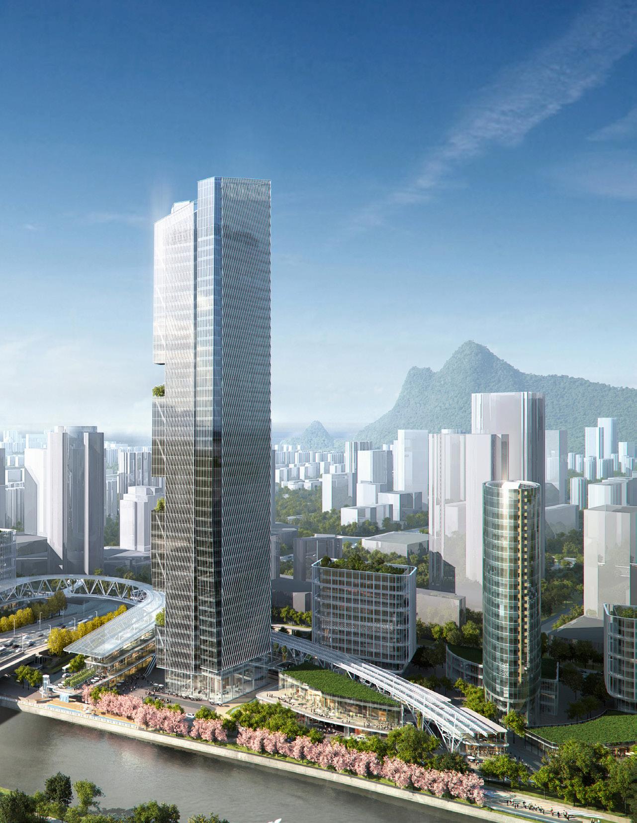
Inspired by the rich history of Suzhou’s gardens, bridges, and waterways, the mixeduse development creates diverse and engaging environments. Located on the banks of the Grand Canal, the project works as a gateway to the new High-Tech Central Business District. A family of trellis and shade structures provides pedestrian comfort and protection, renewable energy, and project identity throughout the site. Five midrise office towers on the site’s north side enhance the street wall facing the central business district. The two gateway towers flanking the existing Lion Mountain Road feature triangular, ‘pinwheel’ tower plans to take advantage of long, unencumbered views of the Grand Canal. Outdoor tower terraces bracketing Lion Mountain Road Bridge symbolize the garden character of the city and create a distinctive figureground silhouette from Lion Mountain Road.
Role Included:
• Project team leader: directed and delegated design tasks to project team members
• Managed project staffing requirements
• Collaborated with landscape architect to design public realm, including trellis, shade structures, and retail promenade
• Produced concept diagrams, project renderings, and design presentations
• Provided technical oversight for all aspects of the project
• Organized competition deliverables and presentations


 Building integrated PV and solar hot water collectors
Planted “Green lanterns” integrated into trellis structure.
Filtered canal water utilized to improve thermal comfort throughout public space
Building integrated PV and solar hot water collectors
Planted “Green lanterns” integrated into trellis structure.
Filtered canal water utilized to improve thermal comfort throughout public space


Site Plan Lion Mountain Road Hotel and Serviced Apartment Tower Office Tower Office Tower Library/ Shared Workspace Retail Promenade Hotel Ballroom


Existing Office Tower Office Tower Office Tower Office Tower Office Tower Retail Promenade Cultural Center


Operable


Dining Food and
Ventilation Panel Solar Shading Fin Gym Bar Winter Garden Pool All Day
Beverage Roof Top Axon: Hotel Amenities Typical Exterior Wall
西侧的办公室可以利用共享中庭来加强楼层贯通,引入自然,或形成聚会、会议或培训空间
Optional office stacked city-side atria facilitate interconnecting floors, introduce nature, or create gathering, meeting or training spaces

高区办公标准层
Typical Office Floor - High Zone
标准层面积: 1540 SM
Floor Area
楼层有效率: 80% Floor Efficiency
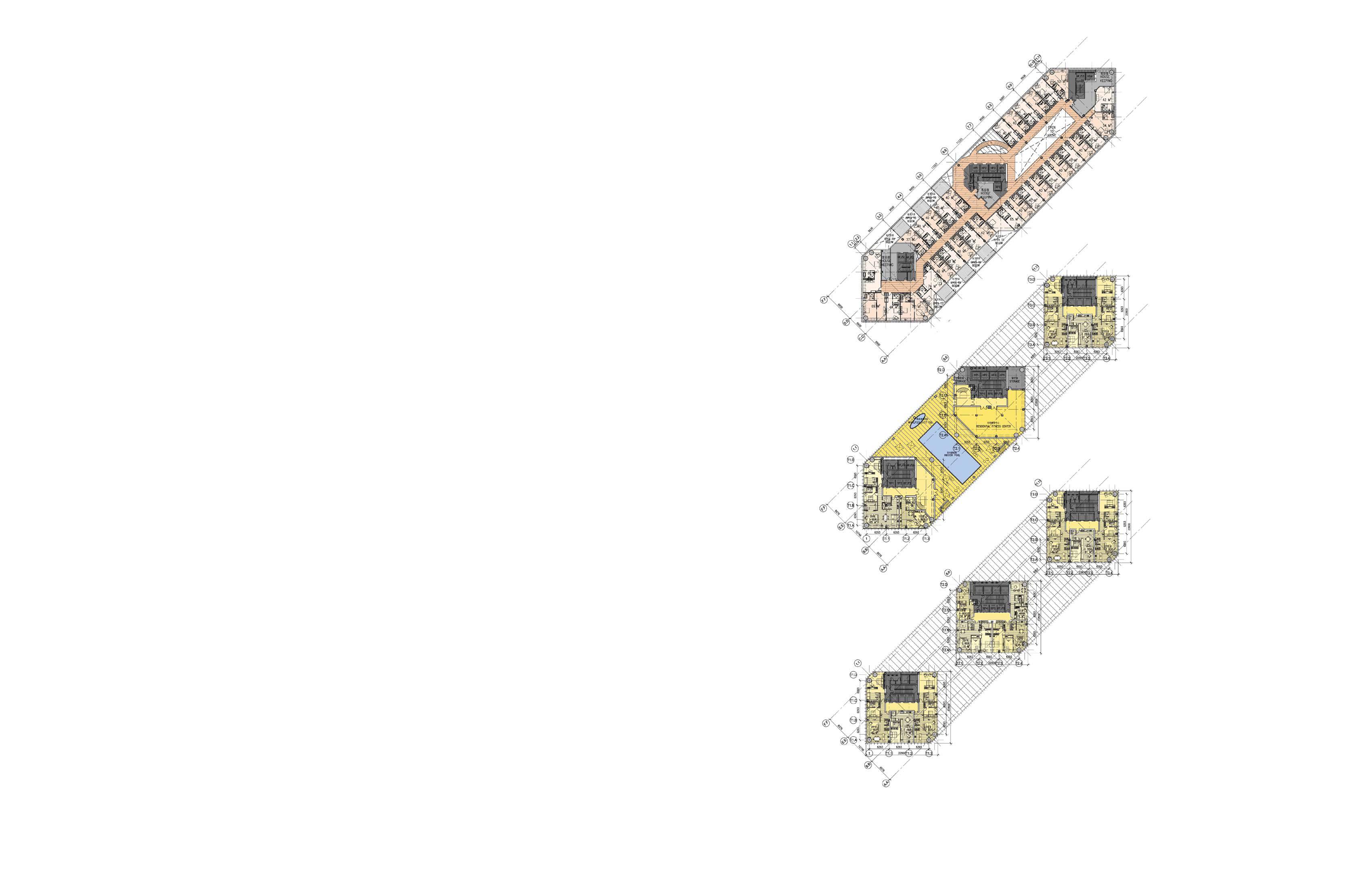
Hotel Plan
优化办公平面,提供合理进深、强化转角办公空间、打造灵活的平面布局
Office Plan - Upper Zone
Workplace Plans With a Variety of Consistent, Corner, or Flexible Office Spaces
低区办公标准层
Typical Office Floor - Low Zone
标准层面积: 1650 SM
Area
楼层有效率: 78%
Efficiency
E HK HFS HFS V SA HX SA HX SA HX SA V V AS M P IT STG P 65 sm 60 sm 80 sm 70 sm 60 sm 60 sm 70 sm 60 sm 65 sm 60 sm 60 sm 60 sm 60 sm 60 sm 56 sm 60 sm 60 sm 60 sm 9800 6800 10000 10000 10000 竖向共享中庭和公寓电梯相连,强化用户的集体感及归属感 residential elevators promote a sense of community and belonging M E IT HP HP HP HK HFS HFS V V V P P M 70 sm 45 sm 65 sm 70 sm 80 sm 40 sm 60 sm 50 sm 55 sm 55 sm 45 sm 45 sm 45 sm 45 sm 45 sm 45 sm 45 sm 45 sm 45 sm 45 sm 45 sm 45 sm 45 sm 12800 9800 10000 10000 10000 高效塔楼布局、结构及核心筒设计 Structure Core
Optimal
9000 7000 9000 9000 Z-2 Z-2 Z-2 Z-2 Z-2 Z-2 Z-1 Z-1 Z-1 SF Z-1 Z-1 Z-1 WC T IT P V WC V SF E M V M
Floor
Floor
Z-2 Z-2 Z-2 Z-2 Z-2 Z-2 SF WC T IT P V WC V SF E M M V M
Serviced Apartment Plan
Plan - Lower
Office
Zone

Ssiger International Plaza
Cixi, China
Hotel and Residential (140,000 m2 GFA, Height: 208m) - Unbuilt
Owner: Ningbo Ssiger Real Estate Development
Lead Designer: Brian Lee, SOM Partner
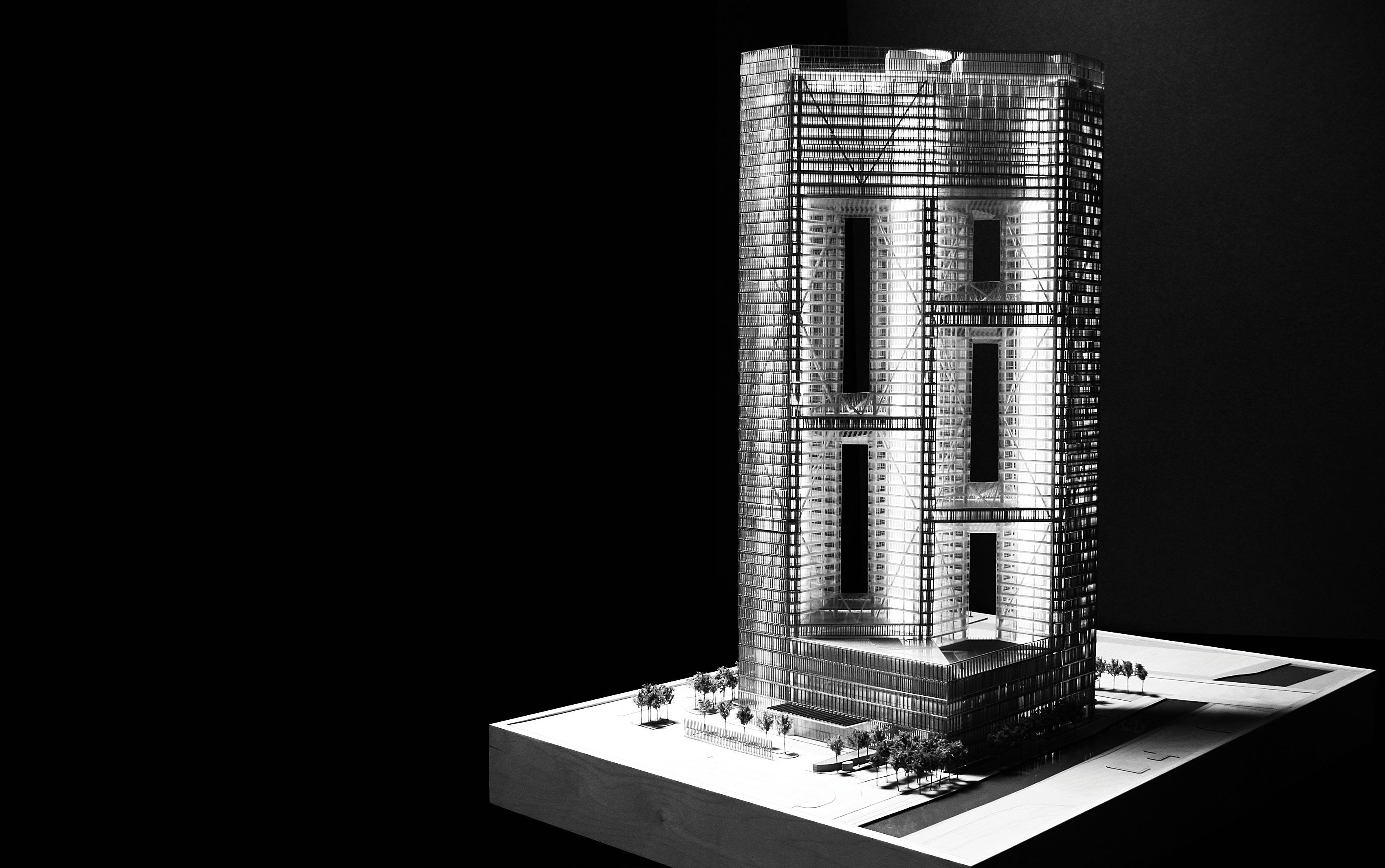
The design of Ssiger International Plaza is the product of client programmatic requirements for three residential towers and a separate hotel tower on a site with a small footprint. The solution that met the client’s criteria was one in which the hotel guestrooms span the tops of the three residential towers, positioned from corner to corner diagonally across the site. Placing the hotel at the crown gives the building a uniquely recognizable skyline presence. The tower base houses public and back-of-house hotel programs. Bridges between the towers provide code-required refuge areas for emergency exiting, strengthen the tower superstructure, and host residential amenity functions. Five large apertures between towers allow light, air, and views to pass through the building mass to the horizon.
Role Included:
• Developed interior architecture including tower cores, prefunction, convention hall, meeting space, and hotel BOH
• Produced concept diagrams, project renderings, and design presentations
• Led coordination with MEP and Structural disciplines
• Produced SD and DD documentation for residential, hotel, and hotel amenity spaces
Design Concept
The building organization is the result of a lengthy, iterative series accommodate the requirements of both the program brief and
These were:
“How can semingly
“How can a single building a semingly conflicting, issues?”
1 Three Point Towers Ideal site disposition for apartment programs
2 Three Towers with Hotel Tower Behind Hotel cannot overlook apartments
3 Volume Unification Hotel Placed on Top
4 Framing Massing frames views of city hall
5 Linking Amenity and refuge areas horizontally connect towers
6 Expression
One homogeneous building skin


Hotel Amenity Apartment
Self Shading
Perforated vertical fins shade perimeter glass. Operability is automated to optimize sun shading throughout daylight hours.

Natural Ventilation and Daylight


Passive cooling through cross ventilation is encouraged via unit layouts in conjunction with operable casement windows. Each residential unit receives southern daylight exposure; most units receive ambient daylight exposure from three facades.


ELE ELEVATION
Section Through Vertical Fins
Section Through Operable Windows
Mechanical Cooling


 Mechanical balconies, located along the northern facade of the residential floors, contain unit dedicated VRVs for cooling.
Section Through Mech. Balcony
Hotel Guest Room
Hotel Guest Room with Balcony
Mechanical balconies, located along the northern facade of the residential floors, contain unit dedicated VRVs for cooling.
Section Through Mech. Balcony
Hotel Guest Room
Hotel Guest Room with Balcony


