Commercial heating

Energy in motion
How engineers created the optimum services solution for audiences and dancers at Sadler’s Wells East


How engineers created the optimum services solution for audiences and dancers at Sadler’s Wells East
Building services engineers are under increasing pressure to deliver energy efficient heating without compromising occupant comfort, building performance or heritage. This month’s special highlights how they are rising to that challenge through innovation, fine-tuning, and a focus on detail.
At the British Library’s Grade I-listed building in St Pancras, London, a landmark solar heating project has generated more than 200MWh of renewable energy in the past year. Part of a wider decarbonisation strategy, the system represents a significant step towards net zero for one of the UK’s most iconic cultural institutions (page 28).
In another example of forward-thinking design, Andy Pearson reports on how Buro Happold met strict acoustic demands at Sadler’s Wells East, to ensure the hum of HVAC systems doesn’t interfere with the audience’s connection to contemporary dance (page 34).
Efficiency upgrades take centre stage in a study by FairHeat’s Simran Chaggar, who lowers boiler setpoints in two commercial buildings to explore their readiness for nextgeneration heat networks. As Chaggar explains, reducing operating temperatures is a vital step for legacy buildings looking to integrate with low carbon infrastructure (page 39).
Meanwhile, Lawrence Leask and Chris Ridge focus on a frequently neglected issue: pipework insulation. As they explain, poor insulation can reduce HVAC efficiency significantly, yet is an easy fix that delivers big returns when done correctly (page 31).
Finally, as building owners weigh up decarbonisation options, Aecom calculates the cost of swapping out gas boilers for heat pumps in a cost model on office retrofits. l
l Molly Tooher-Rudd, reporter
Decarbonising heat is central to the government’s strategy for net zero carbon by 2050. Yet commercial buildings are not being retrofitted at the pace or scale necessary to meet our critical milestones. Lack of incentives, the cost to upgrade, available budget and time, site considerations, electrical capacity, and running costs are typical refurbishment blockers.
But now, minimum Energy
Performance Certificate ratings for leasing private rented commercial properties are on the horizon, which will put new focus on decarbonisation of heating systems. The building services industry will have a key role to play in helping commercial building owners identify solutions that offer the most
beneficial operational, as well as environmental, outcomes.
A practical early stage might be a hybrid heating system that combines air source heat pumps with existing heating infrastructure. Even a modestly sized heat pump can decarbonise as much as 80% of the heat in a building, so a hybrid approach is nearly always a fast, affordable and efficient solution. It would leave some reliance on gas boilers, but these can be swapped out later.
At Baxi, we work with designers and engineers to break down the complexities of decarbonisation. Working collaboratively as an industry, we can provide commercial building owners with the support they need to meet their sustainability targets. l
28 A new chapter on solar heat
How a solar project at the British Library generated 200MWh of renewable energy in 12 months
31 The proof is on the roof
Poor pipe insulation can harm HVAC performance, report Lawrence Leask and Chris Ridge
34 Dancing on air
How Buro Happold reduced HVAC noise at Sadler’s Wells East, by Andy Pearson
39 Testing the limits
Simran Chaggar tests lower boiler setpoints in two buildings to prepare them for nextgeneration heat networks
42 Cost model
The cost of retrofitting heat pumps, by Aecom’s Gaby Boyles


The British Library’s ambitious decarbonisation strategy starts with energy reduction at its Grade I-listed archive in King’s Cross. Alex Smith looks at a solar heating and power project that generated more than 200MWh of renewable energy in 12 months
The narrative for the decarbonisation of the British Library will not be straightforward. To achieve its goal of net zero by 20501, it must substantially reduce carbon emissions from its existing buildings at St Pancras and Boston Spa, while also finding space for its rapidly expanding collection of more than 170 million items.
The script for decarbonisation at its existing sites has yet to be written, but the British Library has committed to reducing its energy use by 4% annually. This is particularly ambitious when you consider that this includes energy use at future new developments at St Pancras and Boston Spa.
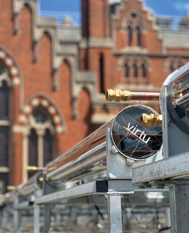
The British Library already has ongoing decarbonisation projects. One of these, at St Pancras, includes the installation of an innovative roof-top solar hot-water and power system, which went live last year.
The project involved the installation of 950 Naked Energy VirtuPVT and VirtuHOT collectors across 712.5m2 of the library’s roof space. VirtuPVT is a tubular hybrid solar collector that generates both electricity and heat from a single device, and VirtuHOT, is a solar thermal collector.
Readers may be familiar with the VirtuPVT as it won a CIBSE Building Performance Award in 2021, in the Product or Innovation of the Year –Thermal Comfort category.
The British Library is Naked Energy’s biggest project to date, and was made possible partly because of the low profile of the company’s collectors. This, according to Alex

Project team
Client: British Library
Solar thermal collectors: Naked Energy
Project manager: CBRE Global Workplace Solutions
Installer: Convert Energy
Mellor, Naked Energy’s director of engineering, helped the library win planning approval on its Grade I-listed roof. ‘It is important that the collectors are not visible from the street, and that enabled us to get through planning,’ says Mellor. ‘We had to stay below the parapet, and our product is compact and has a very low profile of 26cm.’
The PV cells are also at an angle within the tube. Other solar solutions would have had to be tilted at an angle to work efficiently, Mellor says, and would have needed to be mounted on racks or A-frames, which would have made them visible from the street.
“We used a wind tunnel and CFD analysis to understand the wind lift”
The Virtu collectors have also been designed to be resistant to wind. ‘We used a wind tunnel and CFD [computational fluid dynamics] analysis to understand the wind lift compared with other technologies,’ says Mellor.
‘Before we did this work, we thought that we wanted less air underneath the tubes to prevent wind lift, but it’s actually the opposite. The Bernoulli principle means that, if there is high velocity over the top, there will be static pressure underneath, lifting the collector. We created holes in the frame that allow the pressure to be equalised.’
This, however, raised the risk of creating access to nesting sites for London’s pigeon population, so Naked Energy designed the holes to be small enough to stop ‘bird ingress’.
There are 240 hybrid and solar thermal collectors on the British Library scheme. Both types have a solar thermal flat plate absorber to heat water flowing through the system, which can be used for sanitary hot water or process heat up to 80˚C.
In the VirtuPVT collector,
monocrystalline PV cells bonded to the absorber convert solar energy into electricity, with typical PV efficiency of around 20%. Each set of five hybrid tubes is equipped with a micro-inverter, which converts the DC electricity to AC electricity, to be used throughout the building.
The absorber is housed in an evacuated borosilicate glass tube, with the vacuum minimising thermal losses to ensure optimal heat output.
According to Mellor, the system is suited to new or existing buildings. ‘Collectors can be integrated with heat pumps as part of the electrification of heat and hot water, or they can be specified to reduce gas consumption in situations where it is difficult to decarbonise or where it is being planned for the future,’ he says.
The British Library is in the latter category, as its heating, hot water and dehumidification systems are powered by gas. Under its sustainability strategy1, it has pledged to replace these with a heat pump system or connect to a local heat network.
Mellor says this range of collectors are most appropriate for commercial and industrial customers that have year-round heating consumption and, in particular, hot-water demand in the summer.
At the British Library, 1.4 million annual visitors create a large hot-water demand throughout the year, as does the heat-driven dehumidification system, which controls humidity to protect the books and manuscripts.
‘This big summer demand makes the project appropriate for such a

system,’ says Mellor, who adds the heat from the collectors used in the summer is divided equally between hot water and the low temperature hot water (LTHW) feeding the dehumidification system. Solar heat from the collectors is also used for space heating in cooler months. In total, the installation supplies 4% of the library’s space heating and domestic hot water.
The British Library’s humidity control system uses steam and desiccant dehumidifiers. The heated water from the collectors contributes to the latter by heating air to 60°C, which then passes through the dehumidifier to drive out moisture.
Conventionally, this is done via a ‘space heating loop’ or LTHW headers, and as the Virtu system contributes to space heating, it is also connected to the desiccant dehumidification, says Mellor.
The solar hot water is stored
in a giant 15m3 tank in the library plantroom. When heat is required in the building, it is taken from the solar tank preferentially, and any additional heat required is provided by the gas boilers.
The system uses an intelligent control system that tells the pumps when to run and the valves when to open, for maximum performance. It is remotely monitored to allow the library’s engineers to operate and maintain the system.
The collectors have Environmental Product Declarations, and Mellor says the carbon payback – in terms of embodied carbon and operational carbon savings - is between nine and 18 months.
While the British Library project is Naked Energy’s biggest to date, it does have other, even larger-scale ones – with wider applications – in the pipeline. They include a scheme that is twice the size of the British Library, and which has provision for cooling through an absorption chiller, as well as space heating and domestic hot water.
The company is also working on an integration project in Spain, where solar hot-water collectors are pre-heating a steam heat pump to achieve hot-water temperatures of 160°C.
As for the British Library, the system has generated 186MWh of thermal energy and 14.8MWh of electrical energy in the past 12 months, – which, happily, matches the predictions made at the system design stage. l
References:
1 Sustainability and climate change strategy 2024-2030, British Library, October 2024, bit.ly/CJBLsus24
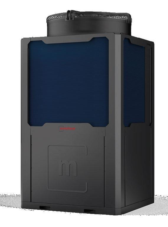
• R290 refrigerant with heating up to 85°C
• A+++ (35/55°C) energy level with high COP
• Cascadable up to 16 units
• Three models: 35kW, 50kW, 100kW www.modutherm.co.uk


Pipework thermal insulation is often overlooked, but can have a devastating impact on system performance if not specified, installed or maintained correctly. Kaizen Energy Consultancy’s Lawrence Leask and TICA’s Chris Ridge say following insulation best practice is a low-hanging fruit when it comes to HVAC efficiency
Thermal insulation of pipework could and should be playing a key role in our national decarbonisation plans. However, thermal insulation is often no more than an afterthought. It should be considered at all stages of the project life-cycle, from design and specification to installation, inspection and aftercare.
Even if we can put in place good specification and installation practices, there is still a huge legacy of poorly insulated pipework.
The examples of poor insulation and specification in this article are taken from recent air conditioning inspections and are typical of issues that are having a profound impact on system efficiency.
The reward for addressing poor insulation is huge – improvement to insulation in the industrial sector alone can save 20,934MWh of energy, equivalent to the consumption of 863,000 households or 1.7 million cars1
The problem is common to all sectors. Poorly insulated plantrooms and pipework systems are the forgotten energy thieves operating in plain sight in our schools, hospitals, offices, and pretty much every other building in which we live, work and play.
So when should pipework be insulated in the plantroom? The easy answer is when there is ‘any application where the heat transfer is
not considered useful’. Heat transfer can only be considered useful in a small minority of applications.
An example of useful heat loss would be on pipework leading from the compressor to the condenser on direct expansion refrigeration lines, where lowering the temperature naturally increases the efficiency of the system. We should also be asking ‘when should we protect the insulation?’ For refrigeration and domestic projects, upgrading a standard flexible foam insulant to a clearly identifiable UVresistant one should be the minimum requirement for any externally located refrigerant pipework.
The key standard for the specification of thermal insulation is BS 5422:2023. This contains multiple tables for the minimum thickness of insulation required in a variety of applications.
It is important that the consultant specifies a particular table rather than a general ‘do it as per BS 5422’ approach. There are multiple tables for similar applications – some will give the client a better operational carbon-reduction result than others, but contractors will invariably assume ‘lowest-cost scenario’ unless instructed otherwise.
There is also a code of practice for the application of thermal insulation

and cladding (BS 5970:2012). This standard is under review, with a new edition hopefully out for public consultation in early 2026.
Bearing in mind the huge legacy of poorly insulated pipework in the industrial sector, we should also welcome the new thermal insulation energy performance standard BS EN 17956:2024. This allows a client to stipulate a minimum energy rating for thermal insulation in the same way that we may stipulate an energy rating for buildings and consumer items.
It should be highlighted that heat network projects typically work to higher specification. With the Heat Network Technical Assurance Scheme due in 2025/26, we should expect thermal insulation of secondary/ communal heating systems to be a key consideration for heat network efficiencies.
The application of ‘flexible pipe lagging’ on small-bore pipework is not regarded as a skilled trade and is generally considered to be part of the domestic plumbing or commercial refrigeration package. However, the application of thermal insulation and cladding in all other scenarios is a skilled trade with a clearly defined route to competence. All thermal insulators should be able to
evidence individual competence with a TICA CSCS Thermal Insulator Skill Card.
Thermal insulation contractors should be able to evidence their organisational capability to carry out this specialist trade. TICA membership is often specified as a minimum criterion for thermal insulation organisational capability, but in many cases it is not. Specifiers have a role to play in ensuring the competence of specialist trade associations on their projects and should not be afraid to challenge organisations to evidence their capabilities.
Pipe insulation is part of a system Thermal insulation sections are just part of the system. Pipe equipment, such as valves and flanges, should also be insulated. One part of the system that often gets overlooked is the pipesupport bracket. Wherever possible, an insulated pipe-support insert should be used. This has a dual purpose; to continue the integrity of the insulation and to maintain the load-bearing integrity of the fixing point.
Where cladding is required, care should be taken to ensure the cladding runs straight through the pipe-support bracket. Points where threaded rods penetrate the insulation and cladding on externally located pipes are classic points of failure. Getting these details
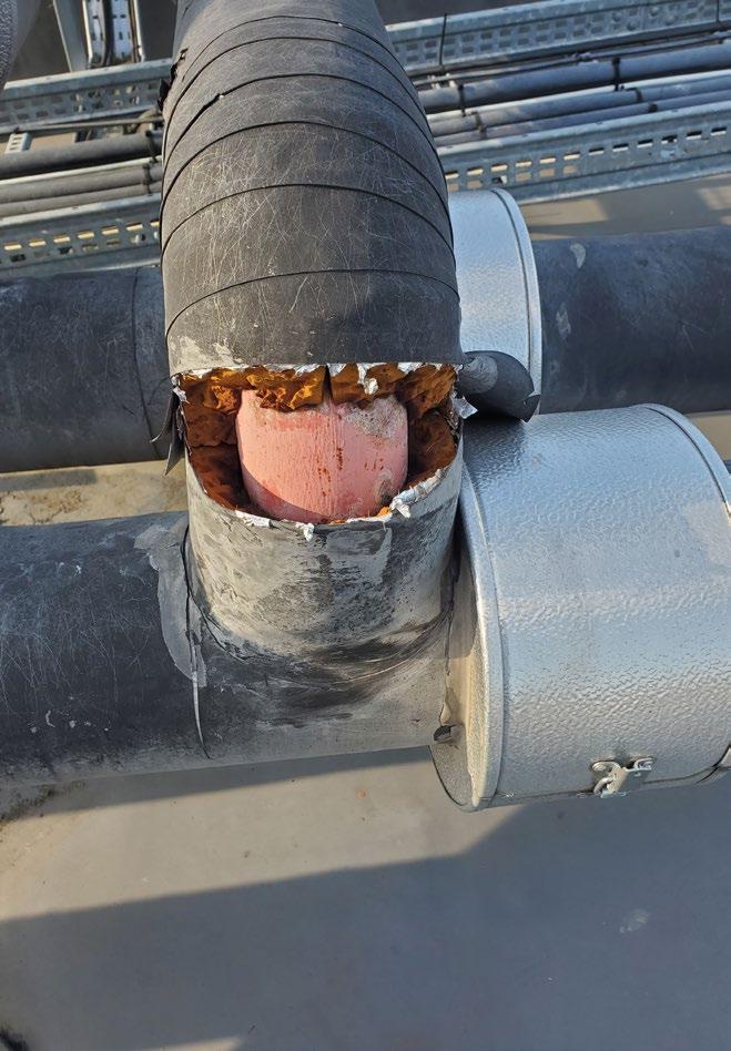
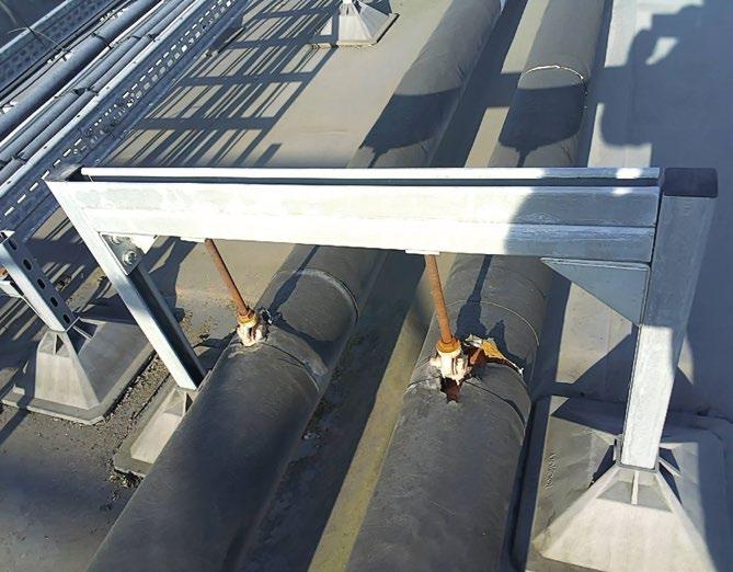
right matters, but it does involve early engagement between the mechanical and thermal insulation contractors.
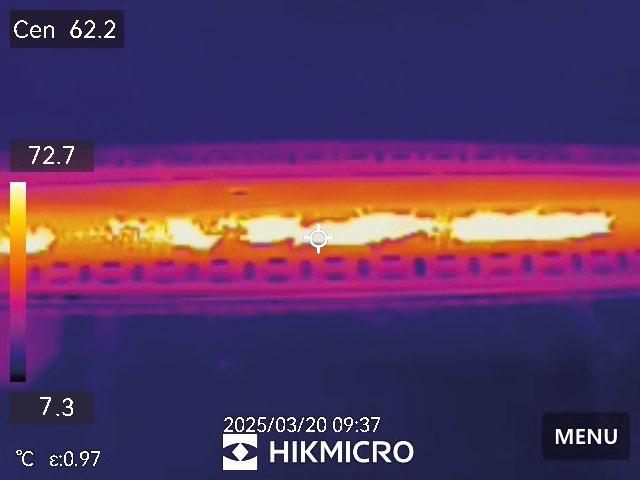
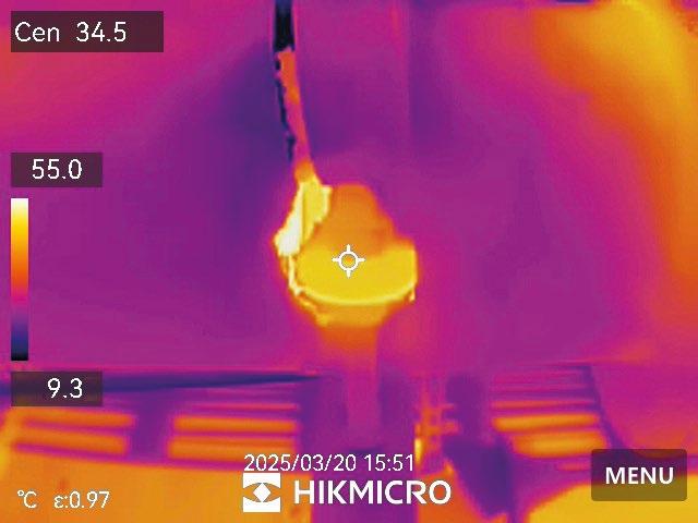
As the name suggests, UV-resistant thermal insulation offers greater resistance to UV damage – but this does not make the insulation UV-proof. Inspection cycles will still need to be in place, even if the risk of degradation is far lower. The standard of insulation is reported with the CIBSE TM44 inspection every five years. However, it is only reported as ‘good or bad’ and there is no further guidance. Where it is suspected that non-UV-resistant flexible foams have been used, an immediate intermediate inspection should be carried out on the externally located insulation.
The five-year cycle leaves ample opportunity for non-UV-resistant insulation to break down and start losing heat from the pipe. Humid air can then reach the surface of the pipe and condensate, leading to corrosion, ceiling damage and mould growth.
Even insulation protected with a professionally installed external cladding system can be susceptible to damage. Any weak point in the system could lead to water ingress and the potential for corrosion under insulation, so there is always a need for ongoing inspection.
There’s also a lot going on inside a building. Every uninsulated valve or flange is adding to the system heat loss. A general rule of thumb is that the heat loss associated with one valve is broadly equivalent to one metre of uninsulated pipe. Yet valve jackets are often not specified – and when they are, they are often not reapplied after being taken off.
For large manufacturing plants and energy facilities, a full audit of the process pipework system should be carried out with a programme such as the European Industrial Insulation Foundation’s (EiiF’s) Tipcheck. This will highlight the return on investment based on a prescribed thermal insulation energy rating; payback for the necessary work is often weeks or months, rather than years.
The issue of poorly insulated pipework needs to be resolved if we are serious about our national net zero ambitions. A focus on strong specifications, good installation practice and ongoing care will make a huge difference over time to saving energy and money. For existing systems, we will have to get onto our roof spaces and plantrooms and tackle the situation head on. l
The authors will shortly publish a white paper, How can government incentivise adoption of thermal insulation of pipework as a key carbon-reduction enabler?
A recent CIBSE webinar can be viewed at cibse.org/ GrowYourKnowledge
l Lawrence Leask is managing director at Kaizen Energy Consultancy and is a CIBSE Low Carbon Energy Assessor – Air Conditioning Inspector with 20 years’ experience surveying HVAC equipment
l Chris Ridge is technical director at the Thermal Insulation Contractors Association
References:
1 Industrial insulation factsheet 2021, EiiF, bit.ly/CJIIFAC21
From

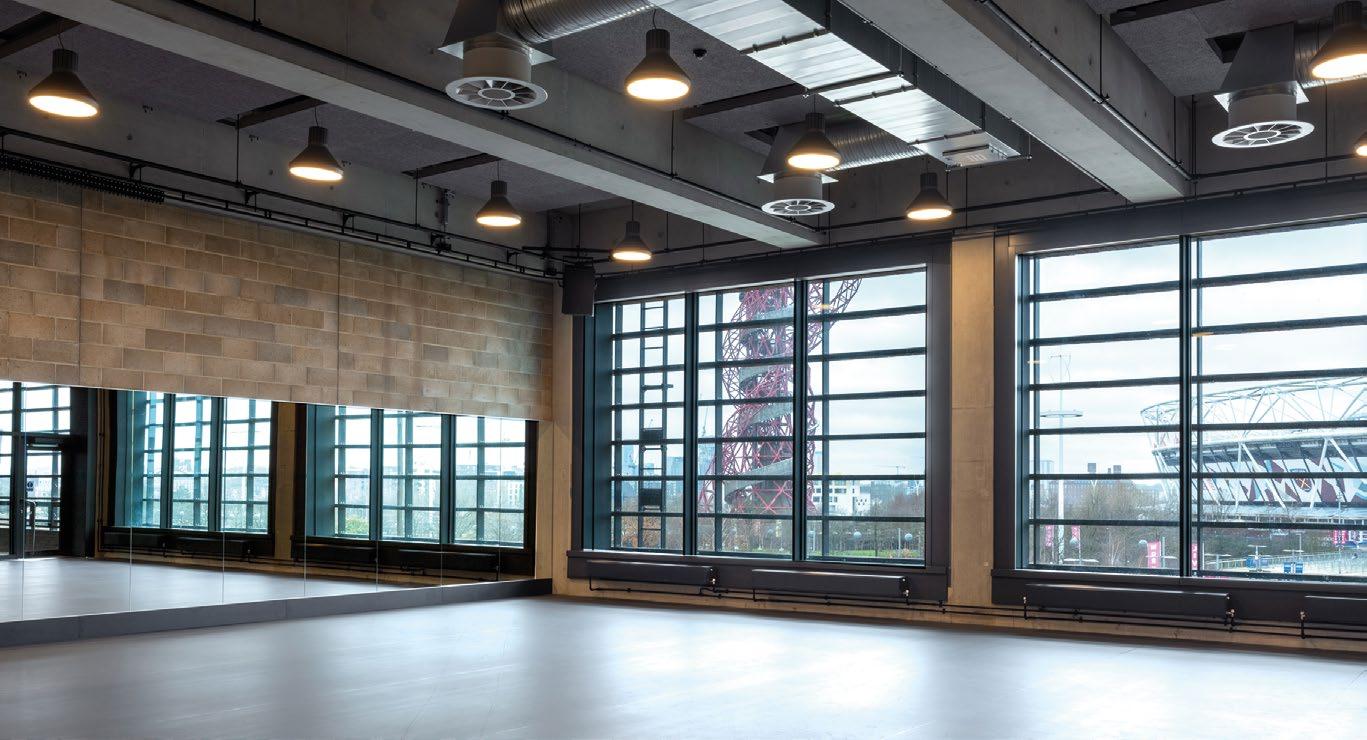
In contemporary dance performance, attention to detail is everything – nothing should break the connection between the dancer and the audience, including the background hum of heating and cooling systems. Andy Pearson looks at how Buro Happold met the exacting acoustic requirements at Sadler’s Wells East
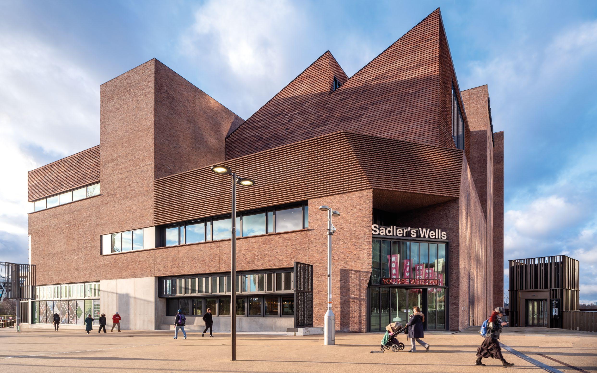
Sadler’s Wells East is the latest addition to the East Bank cultural development, which is transforming London’s Queen Elizabeth Olympic Park. It is a unique building: designed by architect O’Donnell + Tuomey, working with engineers
Buro Happold and theatre consultants
Charcoalblue, it is a purpose-built theatre for dance. Beneath its brick-clad exterior is a 550-seat auditorium, dance studios, a public foyer, cafe, bar, and community performance space.
It’s location meant that Sadler’s Wells East had to connect to the Queen Elizabeth Olympic Park district energy network, which was built to supply heating and cooling to the area ahead of the 2012 London Olympics. All the AHU heating coils in the building are supplied with heat from the district heating system (see CIBSE Journal, August 2011). Connection to it was a requirement of the London Legacy
Project team
Client: Sadler’s Wells
M&E, structural and lighting engineer: Buro Happold Architect: O’Donnell + Tuomey
Specialist theatre consultancy: Charcoalblue
Project manager: Mace
Quantity surveyor: Gardiner & Theobald
Specialist contractor –concrete and steel: Kilnbridge
Acoustic isolation specialist: Mason UK
Development Corporation, as was the building achieving Breeam Excellent.
For an art form in which performers are essentially silent, it is striking that the building’s design is all about acoustics. This is perhaps less of a revelation when you consider that it will be home to groups of dancers jumping and moving in unison. This has the potential to excite structural resonances – and with six dance studios and an auditorium, dancers will inevitably be moving to different rhythms simultaneously. To ensure acoustic and vibration
separation across all performance and rehearsal spaces in this compact building, Buro Happold has adopted an integrated building services and structural engineering approach.
‘Acoustics is the biggest challenge for a building dedicated to dance and performance,’ says Kenichi Hamada, associate director at Buro Happold and the project’s lead building services engineer (see panel, ‘Sound advice’).
The foyer, cafe and entrance to the main auditorium are on Level 0. Directly above the auditorium is the largest of the studio spaces, Studio One, which can double as an event space. To the side of the auditorium is the cafe, above which are stacked five smaller studios.
The auditorium comprises a stage with a fly-tower above. Facing this is the audience on a single rake of seating. The dimensions of the stage are identical to that of the Sadler’s Wells theatre in Islington, to enable
productions to transfer seamlessly from one venue to another. The space is also flexible: by removing and retracting the audience seating, the stage area can be expanded to allow artists to create work for a variety of configurations.
HVAC services for the auditorium are driven by the need to provide fresh air and heating and cooling, to maintain the space at a comfortable 22°C ±1K, in line with CIBSE guidance.
‘HVAC for this space was always going to be an air-driven solution to meet acoustic criteria,’ says Hamada. As such, two AHUs provide fresh air: one serves the auditorium and the other the stage; both are capable of operating as full recirculation and full fresh air, and both incorporate mixing/recirculation dampers and thermal wheel to recover energy from exhaust air.
The stage AHU is the smaller of the two. It is designed to keep dancers comfortable during rehearsals without the need to run the main auditorium AHU. ‘A lot of rehearsals will take place on stage without the audience present, so we decided to split the fresh air supply between stage and auditorium,’ says Hamada.
Fresh air to the auditorium is from a single, large AHU. Air is delivered through wall displacement diffusers
‘HVAC for this space was always going to be an air-driven solution to meet acoustic criteria’ – Kenichi Hamada
at the rear of the auditorium and two displacement ventilation plenum boxes, one either side of the seating at the back of the auditorium. These are dressed in fabric to complement the adjacent acoustic panels.
With the seating extended, the plenum boxes are covered by the bleachers, so that fresh air fills the plenum beneath. A small grille under each seat enables air to enter the auditorium. This is partially covered to help distribute air evenly. ‘We are predominantly cooling, so front seats would get most of the cooled air as they are the lowest. The grilles were restricted to enable cool air to get to higher seats,’ says Hamada.
With the seating retracted, the plenum boxes are exposed. ‘We designed the supply so there is minimum reaction to seating location,’ says Hamada. ‘Even when the seats are

Tempered fresh air from the main auditorium can be diverted to supply additional fresh air to the foyer (right) during intervals, when 300 people could be in the space
retracted, there are still a lot of gaps, so we can still get the air out onto the floor.’
Fresh air supply rates are controlled by temperature and CO2 sensors. ‘We upped the fresh air rate for the dancers,’ Hamada adds, which means the stage AHU supplies fresh air at 16L s-1 per person while the auditorium supplies fresh air at 10L s-1 per person.
The main auditorium AHU also incorporates a mixing box to preheat/ precool the performance space. Air is extracted from the auditorium at high level at the rear of the raked seating, where it is most effective to remove heat from the occupied space. ‘We found the best location for the extract using CFD [computational fluid dynamics] modelling,’ says Hamada.
There is a supplementary extract at high level in the fly-tower serving the stage AHU. ‘We did not want the entire auditorium extract to be from

the fly-tower, because smoke is used for some performances, which would have been affected by the high airflow,’ explains Hamada. The auditorium fire alarm also has a ‘smoke inhibit’ mode to allow smoke effects to be used without triggering the alarm.
To achieve preferred noise criterion 20 (PNC20 – see panel, ‘Sound advice’), duct air velocities have been kept low, at between 3m s-1 to 4m s-1, reducing to 1.5m s-1 at the point where ducts enter the auditorium. ‘Ductwork is really large and duct runs are long to keep the air entry into the auditorium far away from the AHU fan,’ explains Hamada.
Duct-noise control is further enhanced by three attenuators: one at the point the duct leaves the AHU, a second where the duct enters the building from the rooftop plant gantry, and a third just before it enters the auditorium. In addition, the ductwork has been configured to be symmetrical in layout, so it is effectively self-balancing to minimise the use of noise-inducing volume-control dampers. ‘The benefit of having such large ducts is that the fan power is very low,’ says Hamada.
The two auditorium AHUs, along with the building’s 10 other AHUs, are located outside, in a three-storey rooftop plant gantry. AHU cooling coils are supplied with chilled water from two roofmounted air cooled chillers. ‘All the vibrating equipment sits on top of the building and had very strict vibration isolation criteria,’ says Hamada.
The rooftop plant gantry has been designed to be spacious and accessible by crane, to enable plant to be uprated to deal with higher cooling loads from

‘All the vibrating equipment sits on top of the building and had very strict vibration isolation criteria’
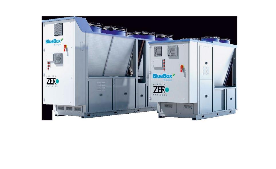
• Eurovent certified performance
• First air-source multifunctional heat pump and chiller unit using propane as a near zero GWP, natural refrigerant solution.

the changing climate. ‘You might have to go for bigger chillers when the plant is replaced in 20 to 30 years’ time, so we’ve built in extra space and risers to allow the diameter of the chilled water pipework to be increased in the next iteration of the building,’ Hamada says.
The studios incorporate windows to allow in natural light and provide views out towards the former Olympic Stadium. Most also have access to terrace spaces. In some studios, natural light is further enhanced by north lights formed by the saw-tooth roof. ‘We did the modelling to find the optimum balance between natural light levels and solar gains,’ says Hamada.
As in the main auditorium, the studio AHUs supply fresh air, and supply rates are controlled by temperature and CO2 sensors to optimise energy usage. The use of dedicated units prevents noise transfer from ductwork serving multiple studios, and enables units to be turned off when studios are not in use.
With the exception of Studio One, which has a PNC of 20, the studios have a slightly more relaxed PNC of 25. ‘We’re still using big ductwork and low-velocity air supplies,’ says Hamada.
Ductwork in the studios is exposed at high level - grilles had to be at least 4.5m above the floor. Because of the continuous movement of dancers, air distribution is generally not a primary concern for thermal comfort in these spaces, says Hamada. What was a challenge, however, was getting the warmed supply air down to low level in winter using the same grilles that supply cooled air in summer. ‘We did eventually find a product that worked,’ says Hamada. Like the main auditorium AHUs, the studio units are fitted with heating and cooling coils and thermal wheel heat recovery.
In studios two to six, heating is supplemented by low-temperature hot water heating panels. These are under local control to give dancers the option to top up heating. In Studio One heating is supplemented by trench heating beneath its glazed outside wall.
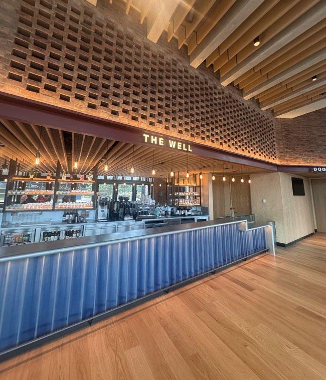
Trench heating is also used beneath the windows in the L-shaped groundfloor foyer and cafe space, which includes The Dance Floor - a public performance stage for community
groups. Acoustics here are less critical, and the aim is to strike a balance between a relaxed and lively ambience.
This space has a mixed-mode ventilation strategy. Actuators open windows when outside air is cooler than inside, but only if the outside air temperature is above 16°C. The thermal mass of the brick and concrete walls provides some temperature stability.
An AHU beneath the public performance stage provides heating and cooling. This operates like a fan coil unit on full recirculation. Air from the unit is ducted to the perimeter, where trench heating is located. Cooling is only intended at times of ‘high occupancy’.
The foyer also serves as an interval
The raked seating in the main auditorium. Each seat has a small grille underneath it to allow air to enter the space
bar for the auditorium, when up to 300 more occupants will occupy the space. At such times, the tempered fresh air supply to the main auditorium can be diverted to supply additional fresh air.
‘There is a mode where windows close so we can divert the auditorium supply air into the foyer,’ says Hamada. ‘This will drift into the double-height space of the foyer, from where it is extracted back to the auditorium AHU.’
Sadler’s Wells East opened in February and the FM team is optimising the HVAC systems’ operation in response to the dance activities.
‘Do it big, do it right, and do it with style,’ would be Fred Astaire’s advice to them. l

Of all the spaces, the auditorium and Studio One have the most onerous acoustic requirements. Theatre consultant Charcoalblue specified a preferred noise criterion (PNC) of 20 for both.
PNC curves are a refined version of Noise Criterion (NC) curves, with lower allowable sound pressure levels across both low and high frequencies. This provides a more sensitive measurement system for ambient noise in indoor environments, particularly in spaces requiring critical acoustic performance.
To help minimise structure-borne sound transmission, the building is supported on a reinforced concrete frame, providing mass and stiffness.
The transfer of structure-borne sound between the two venues is minimised by insulating the studio from the auditorium below with what is, effectively, an empty floor. The studio is placed on 100mm-thick natural rubber bearings mounted on giant trusses, which span the 5m-high void.
Hamada says meeting PNC20 criteria for ambient noise with HVAC systems ‘takes a big effort and a lot of technical thinking’.


Advanced, energy-efficient HVAC solutions designed for low-carbon buildings
Decarbonisation of the UK’s building stock is essential for us to reach Net Zero. At Mitsubishi Electric, our technical expertise and extensive range of innovative low-carbon solutions enable buildings everywhere to significantly improve their energy efficiency and reduce their carbon footprint by transitioning away from fossil fuel heating systems.

If you need a low-carbon commercial heating solution, we can help.


Visit our website to view our full range of low-carbon HVAC solutions. les.mitsubishielectric.co.uk


Lowering operating temperatures will be essential if existing buildings are to plug into the next generation of heat networks. FairHeat’s Simran Chaggar drops the boiler setpoints in two commercial buildings to see how they cope
The UK government has identified low-temperature heat networks as one of the most cost-effective routes to decarbonising heat. Current heat network coverage is just 3% of total heating demand and it is estimated that this figure will need to grow to 20% over the next 25 years.
For new-build developments, integrating with low-temperature networks is relatively straightforward. For existing buildings, however –particularly commercial ones –connecting to these systems presents technical and logistical challenges.
During the coldest months of the year, the operating temperatures of two buildings were lowered to replicate the average emitter conditions of a low-temperature network. The goal was to assess whether the existing emitters were oversized, and to explore how a building’s age might influence performance under these conditions.
The Energy Act 2023 puts in place the regulatory framework for heat networks in the UK. This includes minimum performance standards, consumer protection measures and, importantly, the introduction of heat network zoning, set to be rolled out in 2025.
Most existing buildings within designated heat network zones will have to connect to a local low-temperature network. These zones will be defined by government and be based on the lowest-cost pathway to decarbonising heat in each area. However, building operators may only be given a year and a half’s notice to make their buildings connection-ready, a short turnaround given the level of investigation and potential upgrades required.
One of the biggest hurdles to heat network readiness in existing
commercial buildings in the UK is the incompatibility of traditional heating systems with the demands of modern low-temperature networks.
Most conventional heating systems in commercial buildings are designed for high-temperature operation of 82°C flow and 71°C return. In contrast, heat networks operate more efficiently, with a higher temperature differential and significantly lower flow and return temperatures, such as 75/50°C. This demands that internal heating systems operate effectively with much lower emitter temperatures.
Lowering the average emitter temperature has a substantial impact on radiator performance. A drop in average temperature of more than 20K can reduce heating output significantly if emitter sizes remain unchanged.
There are three key impacts of replacing emitters: increased capital cost; disruption to building operation during upgrades; and risk of not recovering costs if building occupancy or usage changes. These factors can deter building owners from committing to heat network connections without clarity on the true extent of required upgrades.
A typical way to assess whether
a building can perform adequately at lower temperatures is through heatloss modelling: comparing calculated heat losses with emitter capacities at reduced temperatures. This method is fraught with practical issues, however.
Many buildings lack detailed ‘asbuilt’ fabric information, especially older assets. Using estimated U-values based on historical regulations can also inflate calculated heat losses, leading to overestimation of upgrade needs. This underlines the importance of empirical data to supplement – or even replace – purely theoretical models. One way to generate this data is through temperature-lowering tests.
A recent case study explored the potential of temperature-lowering tests across two buildings on a wider estate. The objective was to simulate the impact of connecting to a 75/50°C heat network, with an average operating temperature of 62.5°C, using existing systems, and to determine whether the buildings could maintain occupant comfort with existing emitters.
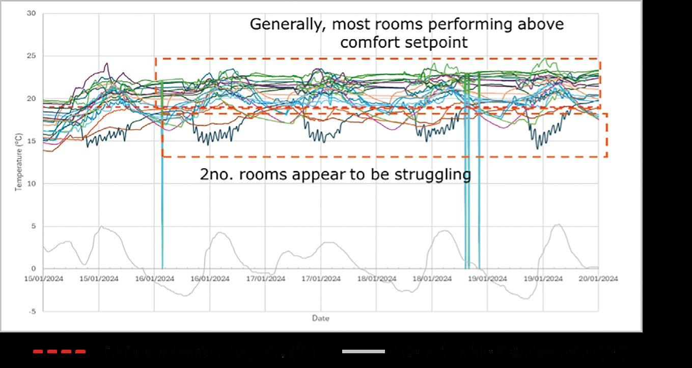
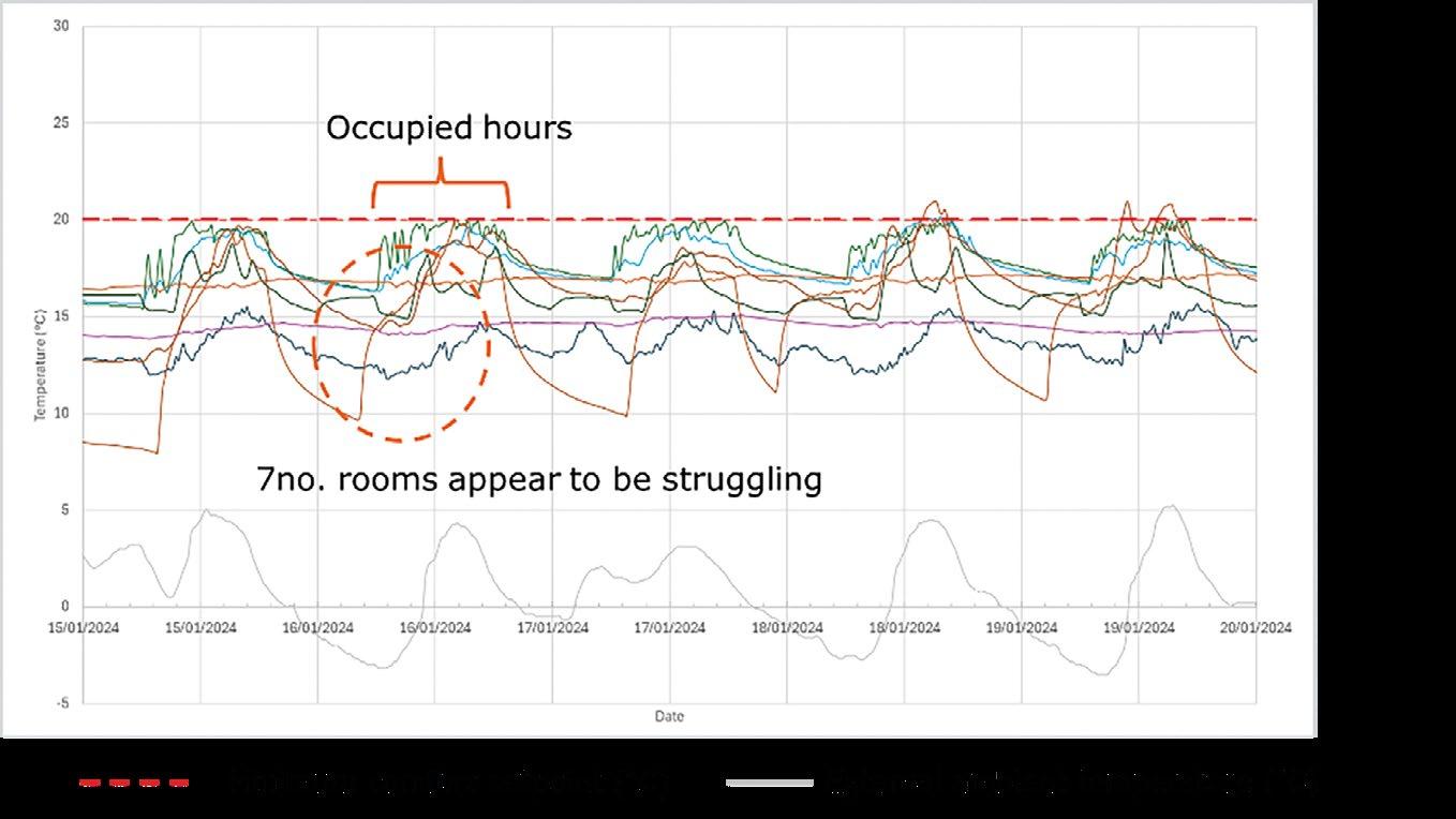
To replicate this, both buildings had their boiler setpoints lowered to 65°C and were compared against a required comfort setpoint of 19-20°C.
The newer building operated with an average emitter temperature of 61°C during the test, with most rooms remaining above the comfort setpoint (Figure 1). However, two rooms struggled to meet the target. On comparison with baseline data, it was evident that these rooms had issues prior to the test, suggesting the reduced flow temperature did not cause a decline in performance. This indicates that minimal or no emitter upgrades are necessary.
In contrast, seven rooms in the older building failed to meet the comfort setpoint (Figure 2). Poor performance was seen during occupied hours, with data indicating that many of these rooms were underperforming before the test. This suggests both pre-existing deficiencies and exacerbation because of lower flow temperatures. In one room, ambient temperature dropped from 15°C to 12°C under identical external conditions post-lowering, indicating a measurable performance decline as a direct result of the test.
The contrasting performance of the buildings highlights a number of insights. First, the newer building’s issues are localised and mostly pre-existing. Further, the older building will probably require substantial emitter upgrades for successful heat network integration.
Temperature-lowering tests provide real-world, building-specific data – helping to reduce the likelihood of unnecessary upgrades – and improve cost certainty by clearly identifying where emitter replacements are genuinely needed. They also boost confidence among building operators by reducing the perceived

risk of connecting to low-temperature heat networks.
There are some challenges to this approach, however. One is the cost of installing ambient temperature sensors. Accurate assessment requires flow and return temperature sensors on each heating circuit, which can be costly


to retrofit. Despite these limitations, temperature-lowering tests are a valuable, evidence-based approach to informing retrofit decisions and avoiding over-engineering.
l Simran Chaggar is a senior engineer at FairHeat


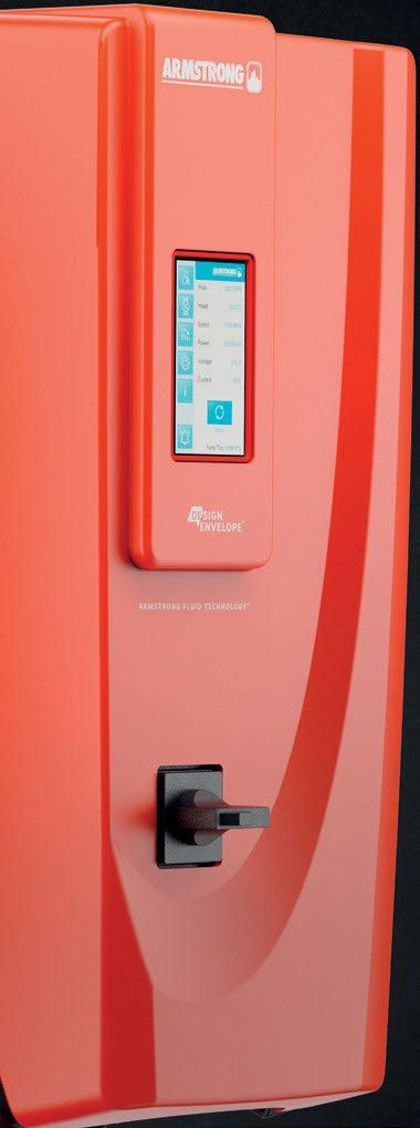


Armstrong's latest Design Envelope Tango models have a unique, integrated suction and discharge flow control valves which enable the flow to be easily switched between fully open for optimised parallel operation or isolated full to either individual pump, allowing for servicing without any downtime.
Unique design incorporates depm technology, optimised hydraulics and demand based controls for reduced energy consumption and maximum cost savings.
Extended range now up to 30kW
Scan the QR code to learn more about the Design Envelope Tango Pump range
Contact us to see how we can support your next project 08444 145145 ukhvacsales@armstrongfluidtechnology.com
A compact low-carbon dual pump that ensures uninterrupted service, even during maintenance.


The cost and considerations of replacing existing heat and cooling equipment with an air source heat pump using natural refrigerants, by Aecom’s Gaby Boyles
Decarbonising an office or commercial portfolio presents numerous obstacles, ranging from planning, financial and legislative challenges to competition within the marketplace for green office space.
Continuous improvement of building performance in terms of Part L and reducing carbon emissions has resulted in building owners looking to replace non-renewable technology with electric plant and equipment. Tenants, too, are seeking green buildings that support environmental sustainability while offering a comfortable workspace that enhances employee wellbeing.
Large-scale capital investment in decarbonisation poses significant financial challenges for landlords, including lost income when tenants vacate buildings during refurbishment.
The growing number of air source heat pump (ASHP) manufacturers in the
marketplace is reducing the cost per kilowatt of large-scale heat pumps, making them a more attractive solution.
The latest models are available in smaller units that can be installed in modules. These operate more efficiently, matching actual building demand in real time. This approach does come with a cost premium, however.
Technical innovation and regulatory pressure to phase out refrigerants with high global warming potential (GWP) are driving the uptake of natural, lowGWP refrigerants such as propane and CO2. The availability of these in ASHPs is limited at present, and attract a cost premium. There are also risks around flammability and system complexity.
Effective office decarbonisation planning requires careful consideration of key factors to produce a robust variability study that supports investment decisions that enhance asset value. For ASHPs, these include:
1. Structure. Implications of increasing potential roof loads, as a result of placing additional plant on the roof, that requires additional steel work; interfaces with existing building elements, such as insulation; potential noise and vibration transfer.
2. Architecture. Requirement for additional plant screens or noisemitigation measures around plant. Formation of new plantrooms at roof level, with structural and service implications. Major architectural interventions, such as recladding the building, as well as associated planning approval implications.
3. MEP. Requirements for wholesale replacement of existing equipment to accommodate ASHP installations, and replacement of obsolete/end-oflife systems. Upgrading of incoming power to support all-electric system.
4. Programme of works. Retrofitting ASHPs can involve a lengthy programme, meaning lost rental income. Consider: design period;
planning applications; notice and decant of existing tenants; tender and construction period; testing and commissioning; marketing and reletting of the building.
The cost model looks at replacing existing gas-fired boilers and roofmounted air cooled chillers with roof-mounted ASHPs using natural refrigerants. The building is a 16-storey office block (one basement level, 15 storeys above ground) with circa 400,000ft² GIA and 270,000ft² NIA. Located in a city centre outside of London, the office reaches practical completion in 2025. The model assumes the building is vacant during works and that the incoming electrical supply does not need upgrading. l
l Gaby Boyles is a quantity surveyor within Aecom’s engineering cost management team and decarbonisation lead
ASHP, including pumps, pressurisation, side-stream filtration, buffer vessels and the like
Adaptions and modifications to existing electrical installation
and modifications to existing BMS
23–24 April 2026
Loughborough University Leicestershire, UK
Submit an abstract for the 2026 Technical Symposium by 16 June 2025 For more information please email symposium@cibse.org Get involved


cibse.org/symposium

Investment of £42m in seven research hubs aims to ensure net zero goals are aligned with public health
The National Institute for Health and Care Research and UK Research and Innovation are investing £42m in seven research hubs across the UK to ensure the country’s transition to net zero also promotes public health.
Three of the hubs – Hearth, Inhabit and Chili – will focus on areas including air movement, ventilation, and IEQ, tackling some of the most urgent health and environmental challenges linked to climate change.
Hearth will address how extreme heat affects health, with a particular emphasis on resilient building design and air movement strategies to keep people cool in future climate conditions. Collaborators include the
Greater London Authority and several universities.
Inhabit will explore how the shift to net zero housing impacts IEQ and human health. With partners incuding the London School of Hygiene & Tropical Medicine and King’s College London, the team will research how ventilation systems can evolve to support healthier, low carbon living.
Chili, led by Professor Pia Hardelid at the UCL Great Ormond Street Institute of Child Health, will investigate the effects of learning environments on children’s health in the context of net zero. The research will provide insights into how IEQ and temperature regulation affect child development and academic performance.
Carrier Solutions UK has launched a new training academy in Stockport, to elevate HVAC engineer training.
The facility offers hands-on experience of a comprehensive range of Carrier, Toshiba, Viessmann and Vokèra heating and cooling solutions, including air-to-air and air-to-water heat pumps, SHRM Advance VRF systems, boilers and smart controllers.
The former warehouse now houses advanced F-gas training rigs and serves as an accredited BPEC training site. Trainees will receive industryrecognised certification, with the added benefit of a 10-year warranty backing their work.
Additional centres are planned for Wakefield, Telford, London Colney, and Plymouth in 2025.
The CIBSE Technical Symposium featured a range of research into natural ventilation, passive cooling, and circular economy approaches for sustainable building performance.
In a session themed ‘Passive design strategies for sustainable and comfortable buildings’, Horreh Todeh Kharman, of Loughborough University, introduced a new method for assessing how external shading devices influence summertime indoor temperatures in naturally ventilated dwellings.
Daniel Zepeda Rivas, from UCL, explored the effectiveness of passive cooling adaptations in homes across Greater Manchester, while Mikel González Pérez, of IDOM, showed how computational fluid dynamics studies of La Nueva Romareda stadium, in Zaragoza, Spain, used the region’s Cierzo wind to optimise natural ventilation and comfort for spectators.
Mathieu Naccarato, of Savills Earth, presented a case study of embodied carbon in mechanical, electrical and plumbing systems, reviewing a hybrid ventilation setup in a secondary school.
Divyanshu Sood, from University College Dublin, offered long-term modelling of energy efficiency and indoor environmental quality in a naturally ventilated home located in a temperate oceanic climate, highlighting the potential of lowenergy residential design.