


Proceedings
14-15 November 2013


Hosted by
 Edited
Dr. Alan Hore
Barry McAuley
Dr. Roger West
Edited
Dr. Alan Hore
Barry McAuley
Dr. Roger West
Published in 2013
ISBN 978-0-9573957-02
Published by The Construction IT Alliance
© Copyright Declaration
All rights of papers in this publication rest with the authors.
This publication is part of the proceedings of the CITA BIM Gathering Conference held in the Guinness Storehouse, Dublin, Ireland, on 14-15th November 2013.
Copies of these proceedings are available from: Dr. Alan V Hore School of Surveying and Construction Management, Dublin Institute of Technology, Bolton Street, Dublin 1 Ireland. alan.hore@dit.ie
Papers are also available on the conference website www.gathering.cita.ie
Cover images were selected from accepted papers.
Graphic design by Print logistics Ltd. www.printlogistics.ie
Website and conference engine by Ex Ordo www.exordo.com
Chair
Dr. Alan Hore
Secretary Barry McAuley
Operations Manager Suzanne Purcell
Conference Manager Leah Cullen
Administrator Bairbre Fox-Mills
Dublin Institute of Technology
Dublin Institute of Technology
Construction IT Alliance
Construction IT Alliance
Construction IT Alliance
Ralph Montague Arcdox
Dr. Roger West Trinity College
Claire Crowley KMCS
Trevor Woods ConstructIT
Dr. Ken Thomas Waterford Institute of Technology
Keith Mellon Jacobs International
Niall Coulston Enterprise Ireland
John Hunt Enterprise Ireland
Brian Lahiff Thomas Garland & Partners
Dr. Alan Hore
Dr. Roisin Murphy
Mr Barry McAuley
Dr. Ken Thomas
Dr. Nenad Cuš Babic
Dr. Roger West
Dr. Jason Underwood
Dr. Avril Behan
Dr. Kevin Kelly
Dr. Andrew Ross
Dr. Niclas Andersson
Dr. Louis Gunnigan
Dr. Ingirige Bingunath
Dr. William Hynes
Dr. Tomo.Cerovsek
Dr. Alan Redmond
Dr. Eugene McGovern
Dr. Matevz Dolenc
Dr. George Heaney
Dr. Oliver Kinnane
Dr. Kevin O’Rourke
Dr. Mustafa Alshawi
Dr. Song Wu
Dr. Colin Caprani
Mr Bernard Voortman
Mr. Dana Smith
Mr. Finith Jernigan
Ms. Laura Handler
Mr. Gregory Howell
Mr Brian Lahiff
Dr. James McDonnell
Dublin Institute of Technology
Dublin Institute of Technology
Dublin Institute of Technology
Waterford Institute of Technology
University of Maribor
Trinity College Dublin
University of Salford
Dublin Institute of Technology
Dublin Institute of Technology
Liverpool John Moores University
Technical University of Denmark
Dublin Institute of Technology
University of Salford
Future Analytics
University of Ljubljana
Anglia Ruskin University
Dublin Institute of Technology
University of Ljubljana
University of Ulster
Trinity College Dublin
Dublin Institute of Technology
University of Salford
University of Salford
Dublin Institute of Technology
Cummins and Voortman
Building SMART US
Design Atlantic
Tocci Group
Lean Institute
Thomas Garland & Partners
University of Dublin


The conference is kindly supported by the following organisations


The Architecture, Engineering and Construction (AEC) sector is known to operate with outdated, cumbersome and problematic processes and practices, that although deliver, lead to unnecessary and avoidable waste. This waste is generated by non-value-adding duplication of effort, abortive work, adversarial administration and poor use of materials and labour. This costs the industry, government and private clients billions and there is also a huge operational and environmental cost from buildings that could be performing with further optimisation.
The coming together of Integrated Project Delivery (IPD), Building Information Modelling (BIM) technology and lean construction practices has the potential to radically transform the AEC sector. The Construction IT Alliance (CITA), is facilitating an International gathering of industry experts and leaders in the areas of IPD, BIM and lean construction practices to discuss how this transformation of the AEC sector will take place. The BIM Gathering is a 2 day conference with keynote addresses from Industry experts, presentations of academic papers, industry case studies and discussion workshops focused on particular sectors in the AEC community, to understand the implications and return on investment of leveraging BIM Technology in planning, design, construction and operations of built infrastructure.
To showcase Ireland as a country that has the professional skillset to design and construct modern buildings and structures utilising the best in class of cutting edge collaborative technologies.
To place BIM and its application in the AEC as one of the core enablers for the transformation of the Irish AEC sector.
To learn, share and connect with representatives from the global BIM community to leverage a leaner and more efficient Irish AEC sector.
To promote the general adoption of BIM by AEC clients, addressing the immediate drivers/ barriers and to develop a more collaborative approach to its more widespread adoption in Ireland and by Irish AEC businesses internationally.
To work collaboratively with representative groups in Ireland in debating the potential of BIM to improve productivity level in the Irish AEC sector.
We are most grateful to our sponsors. Without their kind generosity, it simply would not be possible to deliver the conference to the quality desired. I would particularly like to thank Ralph Montague of Arcdox for his initial motivation to host this event in 2013. Also thanks to Niall Coulston and John Hunt of Enterprise Ireland, who were of great assistance in the planning of the event and, last but not least, to all our event partners who’s continued support is greatly appreciated.
Finally, I must acknowledge the dedication, hard work and significant commitment of the members of the Organizing Committee, the Scientific Committee and the CITA office team. In addition, I would like to thank all the authors for their considerable effort in contributing to such a high quality event.
Dr. Alan Hore Conference Chair 1. 2. 3. 4. 5.Architects, Life Cycle and Standards
D.K. Smith
Dream of Tomorrow
F. Jernigan
Digital Built Britain
D. Philp
BIM as an Intelligent Investment – Imagine the Future
L. Lee
Lean Construction and Technology: Reconceiving the Connection
G. Howell
Creating Interactive Facilities Management Capabilities through Building Information Modelling as a tool for Managing the Irish Public Sector Estates
A.V. Hore, B. McAuley, R. P. West and D. Rowland
Public / Private BIM: An Irish Perspective
J. Deeney, A.V. Hore, B. McAuley
A Theoretical Comparison of Traditional and Integrated Project Delivery Design Processes on International BIM Competitions
M. Serginson, G. Mokhtar and G. Kelly
How accurate is the model? The integration of products and services into the information needs of designers and contractors.
J. Hunt
Investigating the Application of BIM on small scale construction projects
G. Nicholson, J. O’Connor and P. Tobin
Establishing Key Performance Indicators to measure the benefit of introducing the Facilities Manager at an early stage in the Building Information Modelling Process
B. McAuley, A.V Hore and R. P. West
The new normal and a digital construction industry in
The State of the Art of Bridge Information Modelling from Conceptual Design Through to Operation
Designing a Framework for Exchanging Partial Sets of BIM Information on a Cloud-Based Service.
Linking Life Cycle Cost Data Requirements to Parametric Building Information Model
The adoption of BIM within the Public Works Contracts(PWC) suite of
BIM Adoption in University Teaching Programs – The Swedish Case
N. Andersson
Update on the BIM Education of Geomatics Surveyors
A. Behan
BIM introduction into the curriculum of Civil and Structural Engineering students: A project-based active learning approach.
O. Kinnane and R. West
How are the Educational Institutes of Ireland Embracing the Paradigm Shift towards BIM?
M. McDonald and S. Donohoe
Education: Transitional roles for graduates and BIM implementation
H. Salman
Collaborative BIM Learning via an Academia-Industry partnership
K. Thomas, G. Chisholm, B. Dempsey, B. Graham and R. Stubbs
Corrib Onshore Gas Pipeline: The Evolution of Digital Data during the Design and Construction of a Large Infrastructure Project
C. Butler, D. Ward, S, Khan and B. Coyle
Building Information Modelling (BIM) Project Case Study:
E. Nulton and E. Gannon
Case Study: Evaluation of Renewable Energy Strategies Using Building Information Modeling and Energy Simulation
A. Tabrizi and P. Sanguinet
Can The Leading BIM Suites Do It All?
P. Tyrrell
The Curriculum Development of a BIM Resilience Program for the National Institute of Building Science Facility Module
A. Redmond, B. Smith and D. Smith
Application of BIM technologies in managing a modern construction project
V. Janjic
The lifecycle of BIM: A university project case study (MEP co-ordination) T. Cerovsek
163-168
169-173
175-184
185-191
193-200
201-206
Make no mistake, the facilities industry is moving into the information age. We may be kicking and screaming, but we are changing. The smar t ones will embrace the change; the laggards will go out of business. CAD was but a mere drop in the bucket, we did not change the way we worked and we were only automating an existing business process i.e. drafting. Yet, if you were involved in that phase of our history, you saw the elimination of an entire job category – the draftsman. Yet, at the same time, we added new job categories and people were trained and moved into those positions.
The architect must become the point man; they must take a leader ship role. They shall be the ones to identify the new potential that BIM will enable throughout the life of the facility. BIM is the great enabler. It is allowing us the opportunity to get folks working together for change. However, one of my biggest fears remains, that we will not take advantage of BIM as the enabler to incorporate change across the facilities industry. I all too often see the traditional silos only turning into cylinders of excellence.
The architect, as a leader, will need to understand the benefits and potential negatives of each BIM use case across the industry, as they need to be able to describe the business benefits to the owner. Then they need to establish the appropriate data structure, in order to collect the relevant information to support their client, the owner.
In order to ensure we attain the greatest savings in our industry transformation we need to look at the facility far more holistically, as a complete life cycle entity. Many have known about the benefits of life cycle costing, yet in 50 years we are not really any closer with requiring the use of life cycle costing on every project. BIM can be the enabler here also.
The bottom line is that in order for us to achieve this holistic transformation we must adopt standards that allow information to flow across the facilities industry. We must identify the authoritative sources of information and then identify all those who could potentially use that information and develop the trusted information exchange that allows the information to be safely and securely transmitted to each recipient.
With these key ingredients in place, we will see massive change s occur and transition into the information age. Anything less and we will continue to limp along and be seen as a costly an d wasteful industry ultimately to be changed from the outside, because the earth can no longer afford wasteful activities to occur.
At this point human and financial resources are what will ensure that change occurs, the plans are in place, the work has begun, the better resourced the effort, the better and quicker the outcome. Governmental support, acting as a collective taxing authority appears at this point to be the best approach to funding the massive change needed as the industry has indicated little interest in taxing itself, to date. The impact of any government funding is having a positive impact on the entire facilities industry, at this point since the worldwide interests are piqued.
BIM, started as a grassroots effort, among small, nimble practitioners doing what I called little bim. We got great results and learned a lot. Shortly after the turn of the century, a few of us figured out that to move BIM into the mainstream; the effort had to come from the top -down. It was too big of a leap for a small group of evangelists, alone. Without a high level push, it became obvious that BIM would be “little” for a very long time. Organizations such as the US Coast Guard, GSA, and the State of Wisconsin came to the f orefront.
The recent Forfas Report in Ireland gives me hope that, in Ireland, similar high level support is building. For the same reason, I am a fan of the progress being made in the UK.
The British government approach to BIM has caused the industry to wake up. They are mandating significant improvements. The numbers of industry professionals now wrestling with becoming little bim proficient is growing. This is good... more minds focusing on the issue will result in i mprovements, in the infrastructure delivery process and technology. However, by focusing on little bim, the British government has missed (or at least sub-optimized) the opportunities.
Little bim vastly improves design and construction and likely saves some early facility manag ement costs, but the other opportunities that come from BIG BIM are missing, and remain aspir ations only.
Many in the building industry world wide seem to be stuck in little bim, focused on the day-to-day needs of design and construction, perhaps not realizing that there are easier and more productive ways to do the same job… with vastly greater benefit. They inadvertently negotiate against the mselves, not understanding the larger picture.
Little bim is better than what we had before, but why go for halfway measures, when one can have it all? The potential benefits are enormous.1
When I wrote BIG BIM little bim, the concept of BIG BIM was just th at… a concept based on greatly i ncreased collaborative systems and technology that were just beginning to emerge. In the last three years, this has changed.
If the leadership in Ireland seriously considers and responds to the fact that there is another sig nificant step that has emerged in the chronology I describe, Ireland may well become the poster -child for the future of the built world. As Ireland explores next steps, one has the potential of creating a system that gets all of the good from current best practices while embracing the next practices that have demonstrated a more productive path forward. To the good of all.
The technologies now exist… one can access and use them today. Many of the current preconce ptions will need to be looked at... to understand the benefits that come from enterprise/national level BIG BIM. Organ izations such as the California Community Colleges, US Veteran’s Administr ation and the US Department of Defense Healthcare System have embraced a more systemic a pproach that closely mirrors the way that data operates across the internet... and, finding that it can be done effectively and beneficially, TODAY.
Ireland can set the pace internationally. Start by embracing BIG BIM. The tools, processes and technologies are available today. It will require rethinking how your buil ding industry operates and interacts with a wide spectrum of interconnected people, places and things. Step back and explore the first-principles of how the industry works, how owner’s use information and a ssess what tools and processes can today enable Ireland to interact in a world of BIG Data. People in high places can and will champion the cause. They just need clear and convincing evidence of the benefits that come from BIG BIM.
1. Well applied, little bim has already demonstrated reductions in time and costs of about 25%. BIG BIM does the same, but not just for projects. With a BIG BIM process the same 25% improvement begins to apply across the built environment as a whole.
The UK Government’s Industrial Strategy for Construction announced that we are going to be "An i ndustry that is efficient and technologicall y advanced", so what does that mean for the UK?
We have to compete on a new basis, the construction industry is the last bastion of the analogue world and the UK is going to continue to be at the vanguard on the journey to Digital Leadership.
The HM Government Level 2 BIM programme is a key enabling strategy for the UK. Developing the pro cesses, open data definitions and creating a capable, informed work force has not only led to the repeated sa vings of 20%, but also cemented the UK as a leader in vision, policy, capability and results for Digital Co nstruction World Wide. This was demo nstrated by the Fiatech award this year, the first time such an award has been presented to a public body.
In 2012, at the Government Construction Summit, the Ministry of Just ice (MoJ) announced it was embarking on the first early-adopter project under the Government’s Construction Strategy.
Terry Stocks, MoJ, Head of Programme and Project Delivery / Deputy Director Estate Directorate recently declared over 20% savings from their inaugural BIM project, Cookham Wood. The project also saw significant stakeholder benefits; Emily Thomas, the Governor at Cookham Wood, described these by saying, "For the first time I could understand a building design, it allowed me to contribute a nd comment (both positively and negatively) rather than having to look at flat drawings”.
So a year on and half-way through the BIM task group’s programme how is the rollout of BIM across the public estate progressing?
David will discuss the background to the strategy, the developing processes that underpin it and what lessons have been learned through these first path finder projects.
He will also look beyond Level 2 and examine the step changes in industry competitiveness and new opportunities of the next game changer Level 3 BIM and a “Digital Built Britain”.
Announced at the 2013 Construction Summit, “Digital Built Britain” is the brand through which the UK will deliver BIM contributions to the Smart City and Smart Grid initiatives and BIM Level 3 ca pability to the domestic and international markets
Imagine a future where the AEC industry delivers outstanding design quality that is responsive and sustainable; where all communications throughout the process are clear, concise, open, transparent, and trusting; where decisions are performance based and value driven; where all stakeholders are involved from the initiation of the project; where outcomes are innovative and visionary Imagine a future where the intelligent investment of BIM positions Ireland as a global expert and leader of the AEC industry; where BIM positions the design, development and planning professions to achieve mutually b eneficial, long-term, life-cycle outcomes with balanced consideration of economic, envi ronmental and social parameters In relation to the conference themes, five integrated design strategies will be presented.
Theme 1: Cultural Change
Collaborative Construction (BIM + ecologically sustainable design, integrated project delivery, lean construction) is based on a seamless relationship between clients, architecture/engineering professionals and contractors using new project delivery methods and new technologies in building integrated project delivery (IPD).
Theme 2: Lean Transformation
Environmental Leadership (BIM + energy, waste, water) is based on total environmental performance as the interdependence of complex ecosystems of people and services, buildings and infrastructure, space and transport to address the present and future local and global challenges of climate change, population growth and resource depletion.
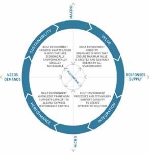
Theme 3: Driving Demand
Industry Innovation (BIM + design, business, engineering) is b ased on integrated environments, processes and systems developed as seamless relationships between usability in design / technology, viability in business / markets and feasibility in engineering / production for multi -cultural and multi-dimensional applications.
Theme 4: Case Studies / Education
Practice-based Use-inspired Research (BIM + education, practice, research) is based on meaningful connections between education, practice and research, built upon case -based knowledge, evidence-based design and performance-based outcomes for the built environment.
Topic 5: National BIM Implementation
Quality Commitment (BIM + procurement, policies, performance) is based on a shared social responsibility, environmental risk and economic reward model where measur es values quality of life, where procurement values design expertise and where policy values cultural advancement to create an affordable and sustainable world.
1 Lean Construction Institute, 2300 Wilson Boulevard, Suite 400 Arlington, Va 22200, USA. Phone + 1-208/726-9989.
E-mail: 1alan.hore@dit.ieGhowell@Leanconstruction.org
E-mail: 1Ghowell@Leanconstruction.org
Abstract Construction Information Technology and Lean Construction (LC) are changing the way construction projects are designed and constructed. While well established, the fundamental principles of LC, basic practices and common vocabulary, continue to coevolve with the development of more powerful Construction Information TechnologyBuilding Information Modeling (CIT-BIM) to support integrated design and the integration of supply chains. This paper fir st explores the difference between "Traditional CPM based Management" (TM) and LC in three domains: "operating system" from an activity based to flow based, "commercial terms" from transactional to relational contracts, and "organization" (authorities and communication protocols) from command and control to distributed and collaborative. The construction industry’s culture and practices will be transformed by the combination of these management practices and the wider application of CIT-BIM.
Keywords Lean construction, Construction Information Technology, Building Information Technology, Theory, Contract, Uncertainty, Organization, Collaboration, IPD.
This paper explores three related and connected issues at the edge of theory and practice and the first focuses on the nature, magnitude and management of uncertainty experienced on projects. The second connects the nature of interaction between people in project organizations within different team structures and management. The third challenges the effectiveness of economic incentives within Integrated Project Delivery (IPD) teams and their governance.
Uncertainty in TM on projects is generally understood as risk to be allocated by contract to one party or another. Each then protects their organization by adding contingency to absorb the uncertainty, insuring against potential loss, or finding a way to shift the risk to another party. A different perspective developed from research conducted for the Construction Industry Institute's
Project Organization Task Force. (POTF-1991) That study reported surprising results as to the nature and magnitude of uncertainty on projects. Initially, participants were asked to mark on a simple matrix the location of their typical project at the start of construction. The axis of the matrix ranged from completely uncertain objectives and uncertain means to clear and stable objectives and means. 1
1 Note that the top right corner is not "Project Complete" but rather the objectives and means to achieve them are clear and stable.
The data was explored with those reporting to understand if there were patterns or clusters of points associated with industry segments or delivery methods at the start of construction. No pattern was discovered. All projects were reported to have some uncertainty as to ends and means as late at the start of construction and some reported a great deal.
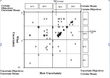
The second set of data in Figure 2 was collected for the "Most Recent Project". It showed both high levels of uncertainty and that 85% of managers underestimated its magnitude and less than 2% overestimated the magnitude of uncertainty as late as the start of construction. In many cases, managers on the same project had very different assessments of the degree, nature and source of uncertainty. Arrows show how assessments had changed as projects progressed. The dots identify projects where there was no change between each manager's initial assessment and later.
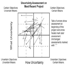
The reports of uncertainty in both figures suggest that regular assessment of the nature and extent of uncertainty is important to keep people's attention on the unknown. People mark where they mark for a reason and usually can explain what information or decision would allow them to change their assessment and improve their ability to complete their work. A careful, patient public discussion with each person's view of the state of project teams is worth the time.
The idea that risk can be allocated fairly by contract is challenged by the extent of uncertainty and the tendency of managers to underestimate it. By contrast, in LC/IPD projects, the teams jointly explore risk and develop strategies to reduce or mitigate the uncertainty that cannot be eliminated. This sort of joint enquiry is particularly important on
complicated, fast moving projects with rapid changes in construction technology. CIT-BIM provides the information and capability to bring people from different locations to solve complicated even complex problems.
First Comparison
Traditional Project Management
Lean Construction/ IPD
Uncertainty
Risk can be minimized and allocated: The owner knows what they want, the designer represents this in the drawings and contractor builds it. CITBIM limited to developing and managing the Critical Path Method of scheduling.
Managed and reduced by the project team to maximize shared gain. CIT-BIM opens new opportunities for conversations to explore alternative solutions and their advantages.
Robert Keidel proposed in Game Plans (Keidel 1985) that organizations were more successful when the "game" they were playing was appropriate for the situation. He presented three games distinguished by the ends and means
relationships at the corners of the triangle in Figure 3. Football, the North American sort, is a game sequential dependence, a game of control. Scoring results from a series of planned events. Winning occurs when teams make and stay on their plan and force the other team off theirs. Adjustments to the plan are literally top down: observers high in the stadium relay instructions to the coach on the ground. Coaching develops the skills of individuals, the ability to make precisely timed movements and to respond to changes with preplanned adjustments.
Basketball is an interdependent sport; teams win by managing the flow. Cooperation is a spontaneous response to the unfolding situation. Scoring is almost continuous as players see and adjust to take advantage of momentary overlaps. Baseball is a game of pooled dependence: each player contributes independently to team performance. Filling out the game roster, the line-up is the key planning decision made by coaches. Planning in then sense of predicting a series of actions is relatively, rare, short term and situational; scoring a statistical improbability. Teams with the best pitchers and hitters usually win the World Series.
Keidel uses the triangle to help companies diagnose their situation in terms of interaction and then shapes their "play" to fit the circumstance. For example in Figure 4, he asked managers to mark their organization's current location, where it would be more effective, and then identifying actions needed to align the organization to situation.
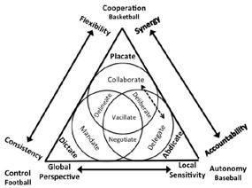

transitions, bringing the leadership appropriate for the circumstance is important as is the ability to shift back into basketball when plans central to success begin to fail.
More recently, Keidel has extended his thinking and added new distinctions to the basic graphic. (Keidel 2003). (Figure 4 combines several graphics from the book.) The labels near each corner suggest behaviour at the extreme with the others suggesting the style that works best in the situation in relationship to the ranges along each side - for example from "Consistency" to "Flexibility". The graphic gives leaders a way to think about and discuss their situation, behaviours needed, and the structure of the organization. Keidel suggests today's business challenges call for organizations somewhere along the double-headed dotted arrow inside the triangle.
In the design and construction of projects, different parts of organizations may be playing different games. Design might begin in the mind of a single signature architect working alone and then become more like basketball as disciplines join to solve interdependent problems. The organization moves toward football, becoming more plan and control driven as work shifts moves to site. Managing the
People working in IPD projects are likely to work in a variety of locations well outside the boundaries of the corporate structures common in the industry of today. Jim Carroll observed during the CII Project Organization Task Force's deliberations, "We need to learn how to play basketball in the middle of a football game." Keidel would add another challenge, "How do we organize baseball stars to play basketball in the middle of a football game?"
Uncertainty
Risk can be minimized and allocated: The owner knows what they want, the designer represents this in the drawings and contractor builds it. CITBIM limited to developing and managing the Critical Path Method of scheduling.
Managed and reduced by the project team to maximize shared gain. CIT-BIM opens new opportunities for conversations to explore alternative solutions and their advantages.
conflicts and challenges that would arise during project delivery." The document includes "Team members will be expected to share information and cooperatively collaborate for the benefit of the Project." The language require the parties to work together for the benefit of the project and to share in its success or failure; it calls on "the better angels of our nature" (Lincoln 1861) to assure those involved cooperate for the benefit of all.
Common sense tells us that the best solutions to complicated or complex problems arise when teams are structured for the situation at hand. Alternative solutions develop when individuals or interdependent teams propose competing solutions and cooperate to refine, improve and select the alternative offering the greatest advantage to the larger project organization.
Structure
Sequential Relationship set by contract. CITBIM supports control.
Fit for the circumstance: Autonomy, Interdependen ce and Sequence. CIT-BIM supports control, cooperation and autonomy and accountability.
Many organizations claim to have invented IPD, produced guides and draft contracts and delivered projects without adopting the LC operating system. For these organizations, IPD is primarily a collaborative contract aimed at optimizing the project and not the piece. These organizations overlook both the IPD™ trademark process created by Owen Mathews of Westbrook in Orlando and the relational contract produced by William Lichtig in 2003. That contract was later adopted by Consensus Docs, a coalition of member associations, and published as Consensus Docs 300.
Mr. Lichtig's objective for the contract was "to create a relationship durable to withstand the inevitable
How is the balance between cooperation and competition to be governed in teams made up of members with different histories, backgrounds and capabilities? Economic motivation within these project-serving teams is set aside by the commercial terms binding their corporations. As a consequence, the extent to which a person contributes to the success of the joint endeavour success may have no direct relationship to money made or lost by their employer.
Theories of individual motivation, Bentham's "Carrot and Stick" (Bentham 1789), Maslow's "Hierarchy of Needs" (Maslow 1943), Herzberg's "Hygiene" (Herzberg 1959), or the Pink's "Self Development Theory" (Pink 2010) miss the powerful influence of the sense of equity or fairness in teams described by Bowles of the Santa Fe Institute and others. Individuals (not sociopaths) have and act from an innate sense of fairness. Adam Smith understood both the power of both self interest, "It is not from the benevolence of the butcher, brewer, or the baker that we expect our dinner, but from the regard to their own interest." (Smith 1776), and our concern for others "How selfish so’ever man may be supposed, there are evidently some principles in his nature, which interest him in the fortune of others, and render their happiness necessary to him, though he derives nothing from it, save the pleasure of seeing it." (1759)
Professor Bowles builds on the latter view and demonstrates how the drive for fairness is more powerful among individuals working together than financial motivations or the other theories listed above. People cooperate for self-interested reasons and because they are genuinely concerned about the well being of others, try to uphold social norms, and value behaving ethically for its own sake. People punish those who exploit the
cooperative behaviour of others for the same reasons. "Contributing to the success of a joint project for benefit of one's group, even at a personal cost, evokes feelings of satisfaction, pride, even in relation. Failing to do so is often a source of shame or guilt." (Bowles 2008) And he support s these claims with well-designed experiments, "The Ultimatum Game" with both individuals and groups that demonstrate this mechanism in action. (Bowles Ultimatum Game)
This simple simulation shows that economic motivators are less powerful than a personal sense of fairness. This simulation has been run in cultures around the world, with larger and smaller amounts of money involved. The results are much the same in every setting. A larger version of the simulation has been conducted with groups of people who stand to gain from cooperation. In this version, it is possible for one participant to maximize their gains by not contributing anything to the success of larger group. Bowles calls these people, "Free Riders", those who take advantage of the situation and maximize their gain at the expense of others. One variation of the simulation allows participants to "punish" free riders by confronting them with their failure to support the success of the larger group
of Free Riders is that they placate others by going along and not entering the competition of ideas. CIT-BIM can bring people to focus on problems and solve them if they are able to work effectively from at a distance.
Third Comparison
Traditional Project Management
Lean Construction/ IPD
"Punishment" begins by privately confronting the Free Rider and asking for a change in behavior. Direct and public confrontation is the next step. When this fails to produce an improvement the Free Rider should be replaced. Teams working in an Integrated Project Delivery should be introduced to these concepts and develop an agreed protocol for identifying and coping with free riders. Person-toPerson, the sense of fairness is more powerful than economic gain.
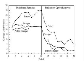
A caution: both Keidel and Bowles are wary of cooperation in the sense of giving in, placating others. Figure 3 places extreme and dangerous behaviors at each corner of the triangle. The danger
Uncertainty
Risk can be minimized and allocated: The owner knows what they want, the designer represents this in the drawings and contractor builds it. CITBIM limited to developing and managing the Critical Path Method of scheduling.
Managed and reduced by the project team to maximize shared gain.
CIT-BIM opens new opportunities for conversations to explore alternative solutions and their advantages.
Structure
Sequential Relationship set by contract. CITBIM supports control.
Fit for the circumstance: Autonomy, Interdependence and Sequence. CIT-BIM supports control, cooperation and autonomy and accountability.
Motivation
Shared financial gain for corporationsequity within teams & punishing free riders. CIT-BIM creates the opportunity for new forms of conversation and cooperation. How it may contribute to coping with free riders is not yet established.
The paper has introduced three connected sets of ideas and their relationship with CIT-BIM. Uncertainty on projects is high, frequently underestimated. Keidel's characterization of teams offers leaders a powerful way to diagnose the situation and a better way to fit teams to task. People have a sense of fairness. At the individual level the sense of fairness is more po werful than the economic theory of behaviour. Teams achieve highest performance when Free Riders are identified and punished by revealing their lack of contribution and then challenging them to do join the conversation or find other work.
A survey of designers and builders agreed that CITBIM is most effective when personal face-to-face relationships are built first and the participants are experienced with the technology. Human connections really matter. Visual conferences are important because people are heavily influenced by facial expressions and gestures. Even face -to-face, people misunderstand even with long experience. (If proof is required, as my wife.) Some anecdotal evidence supports the author’s belief that teams trained in the Language Action Perspective are more effective (Macomber 2001 & 2003).
Today's construction industry has evolved from its historic structure. It has been shaped by the development and application of the Critical Path Schedule. Now comes both Lean Construction, a set of principles and practices about 20 years old, and CIT-BIM. We can already see the combined impact in the way work is managed, commercial contracts are structured and organizations and people behave. The Last Planner® System has brought cross -trade collaboration deep inside projects reducing uncertainty and all that goes with it. Likewise, Target Value Design has raised and extended collaboration reducing uncertainty and risk; "Choosing by Advantages" gives project organizations "a decisionmaking system for yielding sound, reliable, grounded choices (Suhr 1999). These developments have changed where we stand, what we can see, how we think. The culture of the Industry is changing. It will be challenged by the loss of personal contact and strengthened by the ability to bring more minds to bear on the design and delivery of projects.
[1] Bentham, J., Bentham (1789) (http://en.wikipedia.org/wiki/Utilitarianism#Jer emy_Bentham)
[2] Bowles, Samuel (2008) Policies Designed for Self-Interested CIT-BIMizens May Undermine “The Moral Sentiments”: Evidence from Economic Experiments. Science Magazine, Vol. 320. June 20, 2008.
[3] Bowles, Samuel & Gintis, Herbert (2011) A Cooperative Species: Human ReciproCITBIMy and is Evolution. Princeton University Press, Princeton N.J.
[4] Herzberg, F. (1959), Herzberg 1959 (http://en.wikipedia.org/wiki/Frederick_Herzbe rg)
[5] Keidel, Robert, (1985). Game Plans: Sports Strategies for Business. E.P. Dutton, New York, NY.
[6] Keidel, R., (1995). Seeing Organizational Patterns. Berrett-Koehler, San Francisco, CA.
[7] Lichtig, W. A. (2005). Sutter health: Developing a contracting model to support lean project delivery. [null] Lean Construction Journal, 2(1), 105-112.
[8] Lichtig, W. A. (2006). The integrated agreement for lean project delivery. Construction Lawyer, 26(3)
[9] Lincoln, Abraham, (1861) Inaugural Address.
[10] Macneil, Ian, (1979). The New Social Contract. Yale University Press. New Haven, CT
[11] Macomber, Hal, (2001) Reliable Promises
[12] Macomber, Hal. (2003) Linguistic Action: Contributing to the Theory of Lean Construction.
[3] Maslow, A., Maslow 1943 (http://en.wikipedia.org/wiki/Maslow's_hierarc hy_of_needs)
[14] Pink, D. (2010) Drive. Riverhead Books. New York, NY.
[15] Project Organization Task Force (1991). Organizing for Project Success. Special Publication 12-2, Construction Industry Institute, Austin Tx.
[16] Smith, Adam (1759). The Theory of Moral Sentiments. Chapter 1, p.3.
[17] Smith, Adam (1776). The Wealth of Nations. Book 1, chapter 2.
[18] Suhr, Jim (1999). Choosing by Advantages Decisionmaking System. Quorum Press, Westport CT.
1Dr. Alan Hore, 2Barry McAuley, 3Prof. Roger P. West and 4Deborah Rowland
1 & 2School of Real Estate and Economics, Dublin Institute of Technology, Bolton street, Dublin 1, Ireland
3Department of Civil, Structural and Environmental Engineering, Trinity College, College Green, Dublin 2, Ireland
4Department of Facilities Management, Government Property Unit, UK Cabinet Office, London
E-mail: 1alan.hore@dit.ie
E-mail: 1alan.hore@dit.ie 2barrymcauley@gmail.com rwest@tcd.ie 4Deborah.Rowland@cabinet-office.gsi.gov.uk
2barrymcauley@gmail.com rwest@tcd.ie
4Deborah.Rowland@cabinet-office.gsi.gov.uk
Abstract The Irish Government manages estates that are faced with increased pressure on their greenhouse gas emissions, as well as, poorly managed assets that leave it increasingly difficult for an effective Facilities Management (FM) process to be operated. The FM processes represents the most costly stage in the life -cycle of a building and must now take priority in the design process, as the operating and maintenance costs can be up to five times the capital costs, with the business operating costs reaching up to two hundred times the capital costs over the life of the building. In order for Ireland to realise a smarter and better equipped public estate that can respond to increased staffing demands, it is critical that a new dimension of FM be explored through Bu ilding Information Modelling (BIM). BIM could benefit decision-making in FM task by task and can be used as an FM tool specifically in relation to public estates to integrate “digital descriptions” of a built asset. BIM can increase performance, utilis ation and financial information in the maintenance phase, as all the design and built asset information is still present in a single BIM model. The data collation methodology adopted by the authors in this paper included the use of a questionnaire survey that was designed and distributed in collaboration with the Irish Facilities Property Management sector. In addition the UK Government ’s BIM and Soft Landings Policy will be investigated together with its applicability in the Irish AEC / FM sector. The research findings will strongly advocate that BIM can ensure a unique FM approach which can reduce life cycle costs and provide the Irish Government with a more enhanced estate.
Keywords Building Information Modelling, Facilities Management, Public Works, Government Soft Landings Policy, UK BIM Strategy
The Irish Construction sector as indicated by Keane faces its seventh year of decline due to a lack of demand and remains very much in contraction [1] Public expenditure will also continue to be restrained and is likely to remain subdued for some time as the Government strives to reduce the general government deficit to less than 3% of GDP by 2015 [2] . Despite these threatening times there has been
hope provided through the Government‘s plans for an additional €2.25 billion investment in job -rich public infrastructure projects in Ireland. The projects included in this package will be delivered through Public Private Partnerships (PPP) securing value for money for the Exchequer while delivering private sector innovation and commercial and management expertise to the benefit of the State. PPPs allow the spre ad of the cost of financing infrastructure over the lifetime of
the asset which means a number of projects can be developed simultaneously as the capital costs can be spread over the longer term. They also allow the allocation of risk as outlined by Howlin to the party that can manage it best and at least cost [3]. This stimulus package offers the opportunity for the Iris h public sector to ensure that it builds assets that will ensure the long term productivity needs for its people long into the future. The Irish Government have implemented a number of frameworks in tandem with this stimulus package, so as to bring Ireland‘s public sector in line with a number of proposed reforms that include the Capital Works Management Framework (CWMF) [4] and Public Service Reform Plan (PSRP) [5] . The Irish Government‘s National Energy Efficiency Action Plan (NEEAP) for the period 2007 – 2020 is also designed to steer Ireland towards a new and sustainable energy future; one that helps increase security of supply, makes energy more affordable, improves national competitiveness and reduces GHG emissions [6]. Though it is acknowledged by West et al that these frameworks and reforms are a step in the right direction there are no key criteria detailed, in either plan, in regards to future and current Facilities Management (FM) regulation and procedures, so as to ensure that public sector estates are being maximised to their potential [7].
This purpose of this paper is to suggest a more robust methodology that can be used within the Irish public sector in conjunction with the recently announced stimulus package and outlined frameworks. This involves the use of Building Information Modelling (BIM) technologies to support the FM process, to ensure a more enhanced and intelligent Irish public estate.
The authors conducted a literature review of journal papers, professional publications and research articles in regards to the application of BIM as a tool for managing public sector estates. The literature review focused on the three main areas detailed below in order to establish the benefits of using BIM on public sector estates in Ireland:
• The need for change to ensure a more efficient Irish Public Sector Estate
• A move towards a more efficient and intelligent Public Sector Estate.
• Learning from the UK BIM Policy and GSL Policies
The NEEAP outlines how the Government has committed to achieving by 2020 a 20% reduction in energy demand across the whole of the economy through energy efficiency measures. Recognising that Government must lead by example, the public sector has been challenged to achieve a 33% reduction in public sector energy usage over the same period [6]. Nobody can escape from the challenges faced as a country to restore the public finances to a sustainable footing as explained by Wyatt. This statement is further elaborated on by the author explaining that Ireland needs a public service that can lead our economic recovery and meet the needs of people in the years ahead [8] It is now incumbent that the Government find a means to engage the public sector in a positive manner to deliver real reform of the service. This is important to ensure the on-going quality of services but also to provide a means to p ositively engage with the public sector workforce and ensure they remain committed, motivated and focused on service delivery [9] To achieve this it is imperative as stated by Teicholz that the public sector has an enhanced physical environment to operate from. The physical environment can either enhance or impede worker productivity, therefore contributing to its bottom line profits [10] Despite the limited research available as stated by Scully et al. on the position BIM holds in the construction industry in Ireland, there appears to be a consistency of views. BIM holds the potential of:
1. Better pre-construction coordination;
2. Reduced conflicts during construction;
3. Improves visualization;
4. Increases of coordination of construction documentation. [11]
If the Irish Government is to reach the figures made in recent reports then it is imperative that it begins to explore a more advantageous process of commissioning and maintaining public assets. The authors advocate that a more dynamic approach to FM could be achieved through the utilisation of BIM technologies and a partnering soft landing approch, in which could bring about a more efficient management of building stock.
Tracking and managing facilities effectively are difficult owing to the various facilities as claimed by Su et al. Real time maintenance management may be necessary and helpful to control and
manage effectively the maintenance working the building facilities [12] This has resulted in the FM process as outlined by Shen et al having seen a rapid advancement of information and communication technologies, particularly Internet and Web-based technologies during the past 15 years. [13] The effective maintenance and management of buildings could significantly reduce the $15.8B annual costs associated with inadequate interoperability, as reported by a NIST study [14]. Though a number of software tools exist in the Irish FM sector at present e.g. CAFM, CAD, CMMS, IWMS, etc., there is no FM software powerful enough to provide a complete FM package for the public sector [7].
This complete FM package can come through BIM and FM integration. BIM as described by Hijazi and Aziz allows for progressive collection of building data and could play a key role in streamlini ng the data collection process. BIM has the potential to be used as a platform to research and publish information by engaging a variety of stakeholders due to its user-friendly 3D visualisation [15]. BIM technologies as outlined by Sabol offers Facility Managers and building owners a powerful means to retrieve information from a visually accurate, virtua l model of a physical facility [16]. The figure below as detailed by Teicholz shows some of the common benefits of FM and BIM integration
• Ensuring that procurement decisions are made on the basis of whole-life costs, cultural fit and not solely short term financial criteria,
• Ensuring that purchasing will be coordinated between departments where possible.
The same authors warn that there is still a lack of clear evidence on whether and how BIM could benefit decision-making in FM task by task[18]. Sabol outlines further barriers that include current BIM software not being useful to a broad portion of facility workers, the BIM model being overloaded with information and maintaining the currency of BIM files over time will be an issue for consideration. Sabol further warns that the best way forward may be the use of multiple applications with specific targeted capabilities for developing and utilising BIM data. [16]. There are a number of existing schemas in circulation for extracting data from the BIM model, with the Construction-Operation Building Information Exchange (COBie) schema proving to be the most popular. COBie provides an open framework for the exchange and delivery of construction handover information. The COBie is being used by the UK as the standard method to capture and record project handover data. However, if BIM and COBie are adopted as detailed by McCormack et al , we need to not only streamline the flow of information between programmes, we need to address the interface for facility services crews, so they too can leverage these new datasets [19] There are a number of vendors in the process of integrating COBie and CMMS systems, which is an on-going process. Other packages in which export facilities data from the model include FM: Systems, Archi FM, Bentley Facilities, Onuma System, EcoDomas and Graphic systems. These are sets of FM software packages which inte grate with the model and allow advanced options in space management, strategic planning, asset management, etc.
Arayici et al further details through referencing a number of documented case studies the perceived benefits to be realized through the use of BIM in FM:

• Accurate geometrical representation of the parts of the building.
• Faster and more effective information sharing.
• More predictable environmental performance and life cycle costing.
• Better production quality documentation output is flexible and exploits automation.
The use of BIM for FM has seen a rise within recent pilot projects that include Sydney Opera House, Texas A&M Health Centre, University of Chicago Administration Building Renovation, Cookham Wood, etc. The tools as detailed above are radically more sophisticated than what is in place in the Irish public sector and can offer the opportunity to realise a more intelligent estate. McAuley et al believe that in order for the Irish Government to successfully guarantee a more reliable method of cost certainty and greater value, that the Irish Government move towards the mandatory use of BIM on public works projects by following a similar methodology to that adopted in the UK [19].
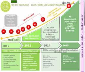
There is a plan for a phased five-year development within the UK where public works projects will be required to use BIM techniques from 2016. This plan was devised around a hypothesis which defined a scenario in which the Government client would have an estate that was smarter and better equipped to face a low carbon economy, with associated reductions in delivery and carbon emissions. The UK have also redesigned their RIBA stages of wo rk to be focused around BIM activities at each work stage, where key data drop points are identified within the overall project process. The aim is to assist design and construction teams in using BIM to provide a more efficient, intelligent and cost effective design process and to offer enhanced services to clients, particularly in relation to the whole life value of buildings [20]. It is expected as outlined by Kuma from all the information available at the moment, that it would appear that the minimum expectations for all stakeholders participating in public sector projects are:
1. COBie UK 2012 Data set;
2. Level 2 BIM Models;
3. 2D PDFs of the drawings. [21]
Figure 2 below shows the road map to be adopted by the UK in the development of level 2 BIM and the GSL policy. This road map details the maturity level expected from the initial Ministry of Justice pilot project up to 2015, where all Government Departments will be implementing 100% Level 2 BIM leading to a digital Britain in 2016. This includes over a four year period the development and piloting of subsequent COBie drops, development of Government Soft Landings (GSL) objectives, automating BIM data to FM, etc. [22].
A large part of this road map is to enhance FM practices within the public sector. Tancred explains that BIM might have emerged from the construction of the built environment sector, but it must not be ignored by the FM industry [23]. This is further enforced by Rowlands in that there are many benefits that BIM can bring FM by aligning the construction and design to the operational use of the asset. This is a real opportunity to make a difference to the way projects are managed in working collaboratively with the construction and design industry [24] One of the current frameworks now in place to capitalise on this opportunity, as further detailed by Rowlands is the GSL approach, which provides a process to ensure BIM is embedded and adopted into future developments in a way that supports facilities managers and will be mandated in 2016 alongside BIM level 2. The purpose is to create the following objectives:
• GSL will be a key element of the design and construction process, maintaining the ‗golden thread‘ of the building purpose, through to delivery and operation.
• Early engagement of the end user and inclusion of a GSL champion on project teams during the design/construction process.
• Combined with BIM it will provide a fully populated asset data set to feed into CAFM systems and modelling will enable planning modifications. This data will need to be maintained throughout the building life cycle.
• Post Occupancy Evaluation will be used as a collaborative tool to measure and optimise asset performance and embed lessons learnt. [21].
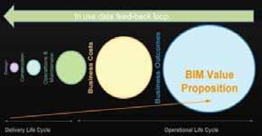
In a recent workshop held by the Construction I T Alliance (CITA) titled ―Integrating Construction Technologies and Process‖ keynote speaker Deborah Rowlands examined GSL in more detail. She explained that through wrapping GSL around BIM one ends up with a better business model with clear outcomes, engaging the client and Facilities Manager early on, to map out improved functionality of the building before construction commences. The value proposition detailed in Figure 3 represents the value that can be harnessed by truly understanding where the majority of life cycle costs come from and in making decisions early on in the design process that can help reduce these costs, therefore resulting in an enhanced business outcome[21].
By integrating GSL and BIM the following opportunities can be realised:
• Collaborative working through co nstruction, design & FM throughout the project lifecycle.
• Operational input and challenge to construction and design to ensure that operational costs are maintained and impact to change assessed.
• BIM provides a fully populated asset data set into CAFM systems and therefore reduces time wasted in obtaining and populating asset information.
• 3D modelling to assist with on-going planning modifications to building use and impact on asset lifecycle. [22].
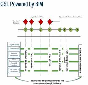
GSL will be measured through the following key areas from the early stage of design into post occupancy, as they pass through the whole BIM process. These measured outcomes as detailed in Figure 4 will be fed back, which will assist in constant review These measures are as follows:
• Environmental: The measurement of energy usage pre and post occupancy.
• Financial Management: The Operational expenditure.
• FM and Commissioning, Training & Handover: Establishing a process and making sure the right people are brought on at the right time.
• Functionality and Effectiveness: What was achieved at the end of it the whole process and for what purpose. [21].
In the same workshop there was a series of round table discussions where it was discussed where Ireland currently are in respect to BIM adoption by Government, key stakeholders, education, industry and individual professions. There was a resounding agreement that the Irish Government should follow the UK Government‘s decision in mandating the use of BIM on public sector projects. The legal mandating of BIM can be a driver to make the industry more technically aware and could provide the tools for Irish Construction firms to compete in International markets [22]. Despite the obvious benefits that the implementation of BIM and the GSL would bring in re-engineering the FM sector in Ireland, there is at present no current sign of the Irish Government embracing either. The reality is that this is highly unlikely, as the GCCC contracts would have to provide BIM procedures or an execution plan template, as part of the CWMF guidelines, which at present seems unlikely due to low prices been already achieved [25] The Irish construction industry as stated by Hore et al. appears unaware or disinterested, lagging far behind in the adoption of these technologies and working procedures. This puts our industry at serious risk of becoming irrelevant in the global market, particularly at this crucial time when we need to export services and expertise [26].
The authors primary data collation methodology involved an extensive survey that was designed and distributed in collaboration with the Irish Property and Facility Management Association (IPFMA), in order to gauge the level of support for the introduction of BIM to assist in managing the public sector estate. An online questionnaire was created with 15 questions, which was originally piloted by its Board of Directors. The
questionnaire was broken into the following three sections
Early FM involvement: The purpose of this part of the survey was to ascertain the opinion of the resondents with respect to the early involvement of the Facility Manager in the design and construction process
FM and Information Communication Technology (ICT) working together:The purpose of this section is to ascertain the current position of the respondents in regard to the importance of ICT and in particular, as a future tool to support FM services not just at the handover stage but throughout the entire project lifecycle, ICT as a FM tool in managing the Government’s state facilities: The purpose of this section was is to explore current views in respect to the Facilities Manager and ICT / BIM helping to better manage both newly and existing public sector facilities and structures.
After a number of changes were incorporated, it was then distributed to the IPFMA member database, as well as posting the survey link to a number of Irish FM and BIM working group webpages. This generated a total of 38 company responses from a mix of small to large enterprises. The responses to the survey will complement the papers research aim as it provides a snapshot of the current Irish FM sector and the technologies that are now commonly in place within the private and public sector. This will provide the platform fo r the authors‘ recommendation of advancing the Irish public sector estate through the implementation of BIM.
The first part of the survey was to ascertain the company respondent‘s opinion with respect to the early involvement of the Facility Manager in the design and construction process. Only 11 % of the respondents had routinely observed early Facility Manager involvement in the design and/or construction phases of a project, with 5 5% claiming that there was none too little involvement of the Facilties Manager. Despite this, 61 % believed that if the Facilties Manager was involved from an early stage, that he/she could play a major role in improving sustainable construction potential, as well as providing a new cost focus for the building life cycle. There was a belief that the Facilities Manager should have an advisory role within the design and construction phases, as they can eliminate non required items and advise on the best "fit" for the
occupants, as well as enhancing accessibility from a maintenance point of view. By getting an insight from the Facilities Manager in the early construction / design stages could highlight areas that could be changed to improve the running costs of the building, making it perfect sense to utilise their expertise in the design and construction of the building. The Facilities Manager can help streamline the design briefing process through their knowledge of facility operations, such as scale and type of product, amount of people working, support facilities in the building, spatial needs, etc. There are concerns that incorporating the Facilities Manager into the design / construction stage would result in an unnecessary impact on the Architect and would provide too much interference within the Design team. There is also a concern that they may lack the technical and materials costs skills in certain aspects.
The purpose of the second part of the survey was to investigate the importance of ICT as a future tool to support FM services not just at the handover stage but throughout the entire proj ect lifecycle. 79% of respondents still used paper based or a digital copy on a CD or DVD to provide O&M information to their company, with only 21% using WebFM or an O&M system. There were a number of companies that cited BMS and Computer Aided Facilities Management (CAFM) as the main source of transferring information, as well as spreadsheets. One company within the survey responses are using a Revit model and noted that this offered the opportunity to provide a model which is interoperable with FM tools such as Artra, if adopted by contractors during the construction stage. Another company who were also using a Revit model stated that this tends to be overly complicated to be used effectively by FM teams. 86 % of the respondents are very to somewhat aware of the current interest and debate in respect to BIM, with 23% of that number having used a BIM model for Facility Operation and Maintenance. Some of the responses include the use of BIM to model structural alterations in existing buildings to ensure that utilities can be maintained or diverted where necessary, and the use of CMMS system to control schedules and maintain the building and subsequent equipment. Encouragingly one company is currently undertaking in-depth reviews of how to best promote the use of BIM systems on future projects which will investigate BIM from both the construction and FM perspectives. Despite the lack of uptake of BIM in regards to FM there are signs that a number of the respondent companies have significant knowledge when it comes to ICT in improving the overall FM process. Some of these include real-time CAFM systems, RFID tags,
augmented reality of utilities, Helpdesk systems, handheld technology keeping information and billing up to date and BIM for FM packages such as ARTRA, which allow construction models to be populated with as built information, as it becomes available during the installation stage of a project. ICT can be successfully deployed to address a number of inefficiencies that exists in the construction process before the Facilities Manager must try and rectify after handover of the building , these include the use of integrated BIM systems throughout design, construction and maintenance of the building. By using an integrated package from the start, one can only help to minimise deficiencies and aid cost reduction during the running of a building.
The final part of the survey aimed to explore current views in respect to the Facilities Manager and ICT / BIM in helping better manage both new and existing public sector facilities and structures. A total of 69% of the respondents claim that the Irish government should take a similar stance to the UK and mandate the use of BIM. A total of 22% of the respondents have experience working within the public works sector in regards to facilities or property management of existing government assets. Some of the inefficiencies within Irish public sector facilities identified in this section of the survey include decisions based on short term costs, and not life cycle, as well as a lack of coordination between designers, constructors and operators. Some of the respondents indicated that the Facilities Manager if introduced in a consultant role at the beginning of the project can help the Irish Government meet its carbon targets and high energy savings, by ensuring energy efficient systems are installed and are designed to maximise their efficiency through their understanding of how the building will be used. The Facilities Manager can not only provide information about the buildings and the service within, but also the occupiers actions and, to a great extent, they can influence these actions to be more sustainable.
The results from the survey show that there is little involvement of the Facilities Manager during the early stages of construction, despite a strong claim to the significant benefits that they would bring to the construction team. There was a belief that the Facilities Manager should have an advisory role within the design and construction phases, as they can help streamline the design briefing process through their knowledge of facility operations. This however, may cause further interference within the design team. There has been little move towards cutting edge technologies from the Irish FM sector in order to streamline maintenance and further enhance lifecycle management. Encouragingly there is significant knowledge demonstrated by some respondents when it comes to ICT in improving the
overall FM process which includes the use of an integrated BIM package to minimise deficiencies and aid cost reduction during the running of a building. There is a strong call for the implementation of BIM on public secto r projects which can help Facility Managers reduce environmental impacts and operating costs.
There is strong evidence to suggest through the literature review and survey findings in answering the authors research objectives, that following in the UK‘s footsteps and implementing BIM and a similar soft landings framework , could help create a more interactive and intelligent Government estate. The current suite of frameworks promoted by the Irish Government do not focus strongly enough on long term life cycle costs and fail to satisfactorily put standard FM procedures and best practice in place. The UK Government have shown the way through their ambitious BIM programme, which will focus on the end users by enhancing the public assets long into the future. The Irish FM sector though stagnating shows encouraging signs of companies who wish to grow through adopting ICT and BIM related technologies. These technologies along with earlier Facility Manager involvement, could help reshape future public assets, as well as the adoption of a similar GSL framework to ensure there is a golden thread between all stages of the life cycle. In order for this to become a reality, it is crucial there is strong leadership from the Irish Government as well as learning from the UK‘s successes and mistakes. This will offer a chance for the Irish construction and FM sector to become a driver internationally and export their skills to the international market.
[1] Kane C, Further decline in construction sector, Irish Examiner, 2010, available at http://www.irishexaminer.com/business/furtherdecline-in-construction-sector-233667.html accessed (24/6/2013)
[2] Percival G, Forecaster raises GDP growth outlook to 1%, Irish Examiner, 2013, available at < http://www.irishexaminer.com/archives/2013/0 410/business/forecaster-raises-gdp-growthoutlook-to-1-227923.html>accessed (27/6/2013)
[3] Departure of Public Expenditure and Reform (2012) Minister Howlin announces an additional €2.25 billion domestic infrastructure stimulus to create much needed jobs, available from < http://per.gov.ie/2012/07/17/ministerhowlin-announces-an-additional-e2-25-billion-
domestic-infrastructure-stimulus-to-create-muchneeded-jobs/> accessed (24/06/2013)
[4] Department of Finance, Capital Works Management Framework – Guidance, Note for Public Works Contracts, Department of Finance,
[5] Department of Public Expenditure and Reform, Public Service Reform, Department of Public Expenditure and Reform, 2011
[6] Department of communications, ene rgy and natural resources, Maximizing Ireland‘s Energy Efficiency -The National Energy Efficiency Action Plan 2009 – 2020, Department of communications, energy and natural resources, 2009
[7] West R, Hore, A.V Hore and McAuley B, Advancing the Facilities Management Process in Ireland through the Implementation of Building Information Modelling within the Public Sector, Proceedings of the RICS Cobra 2013, New Delhi, India, 10th
12th September, 2013
[8] Wyatt R. Public Service Reform – The Balance Sheet, Department of Public Expenditure and Reform, 2012
[9] Deloitte, Reconnect Reorganise Restructure: reform of the Irish Public Sector, Deloitte, 2010
[10] Teicholz E (2005) Facility Design and Management Handbook, McGraw Hil, 2005
[11] Sully R, Underwood J and Khosrowshahi F, Accelerating the Implementation of BIM by Integrating the Developments Made in Knowledge Management: An Irish Construction Industry Perspective, International Journal of 3D Information Modeling , PP 29 – 39, 2012
[12] Yu Chih Su, Yi Chien Lee, Yu Cheng Lin, Enhancing Maintenance Management Using Building Information Modeling In Facilities Management, Proceedings of the 28th ISARC, Seoul, Korea 2011
[13] Shen W, Hao Q, Helium M, Neelamkavil J, Xie H, Dickinson J, Thomas R, Pardasani A and Xue H, Systems integration and collaboration in architecture, engineering, construction, and facilities management: A review, Enabling Technologies for Collaborative Design, Advanced Engineering Informatics, Volume 24, Issue 2, April 2010, Pages 196–207
[14] Gallaher M. P, O'Connor, A C, Dettbarn J L Jr and Gilday T, Cost Analysis of Inadequate Interoperability in the U.S. Capital Facilities Industry, NIST, Gaithersburg, Maryland, 2004
[15] S. A. Hijazi and Z. Aziz, Improving Building Information Handover Practice in Saudi Public
Sector Construction Project, Proceedings of the International Postgraduate Research Conference 2013, April 8th -10th, 2013
[16] Sabbol L, BIM Technology For FM, BIM for Facility Managers, John Wiley and Sons Inc, pp 17-46, 2013
[17] Teichoz P, Introduction, BIM for Facility Managers, John Wiley and Sons Inc, pp 1-16, 2013
[18] Arayici Y, Onyenobi T and Egbu C , Building Information Modelling for facilities Management the Mediacity case study Approach, International Journal of 3-D Information Modelling, 1(1), pp55-73
[19] McAuley B, Hore A.V and West Implementing of Building Information Modelling in Public Works Projects in Ireland, Proceedings of the 9th European Conference on Product and Process Modelling, Reykjavik, July 25 – 27th, 2012
[20] Brady A, Introduction, BIM Overlay to the RIBA Outline Plan of Work, RIBA, 2012
[21] Kumar B, Building Information Modeling: Road to 2016, International Journal of 3-D Information Modeling, PP 1-7, 2012
[22] CITA, CITA Technology Workshop 1, Integrating Construction Technologies and Process, available from < http://www.cita.ie/technologyworkshop1.asp > accessed (19/6/2013)
[23] Tancred G, Introduction, BIM and FM: Bridging the Gap for Success, British Institute of Facility Managers, pp 2, 2012
[24] Rowland D, A Governments View: Bridging the Gap, BIM and FM: Bridging the Gap for Success, British Institute of Facility Managers, pp 3, 2012
[25] McAuley B, Hore A.V, West R and Kehily D, Addressing the Need to Reform Construction Public Procurement in Ireland through the Implementation of Building Information Modelling, Proceedings of the 1st ASEA-SEC-1 International Conference on Research, Development and Practice in Structural Engineering and Construction, Perth Western Australia, 28th Nov – 2nd Dec, 2012
[26] Hore A, Montague R., Thomas K, and Cullen, F, Advancing the use of BIM through a government funded construction industry competency center in Ireland, Proceedings of the CIB W78 2011: 28th International Conference, Paris, 26-28, 2011.
1,2
E-mail: johnp1979@hotmail.com
alan.hore@dit.ie barrymcauley@gmail.com
Abstract: The current economic difficulties have affected most practitioners within the industry and, as a result, many firms and contractors are bidding for fewer projects, resulting in below-cost tenders. It is clear that, many firms and contractors are now operating on thin margins; which makes it increasingly difficult for them to commit to the introduction of new software applica tions and system upgrades. The transition to Building Information Modelling (BIM) from traditional 2D CAD by Irish firms and contractors has been a relatively slow process compared with our international colleagues. There are many reasons for this, including lack of resources, lack of awareness, ignorance, m isunderstanding and adversity. The lack of BIM promotion and BIM training opportunities within the industry has meant that very few people possess the basic requirement to successfully embrace BIM at a level which would be considered efficient. BIM is the new way of operating and it is gaining momentum; the industry simply cannot turn a blind eye to the techno logy or it will be left behind. The industry must therefore adapt and change current working practices in order to compete with other established and recognized BIM nations. This paper will evaluate BIM in the international context and, investigate if these methodologies can be transferred to the Irish construction industry. This paper will also aim to identify obstacles and drivers for Irish firms, contractors and Government Departments with regard to BIM adoption, as well as the behavioral and cultural elements which are preventing BIM adoption in Ireland. It is hoped that the research findings will demonstrate a business case for the implementation of BIM , for both public and private sector organizations.
Keywords: Building Information Modelling, BIM Adoption, Private Sector, Public Works, Social and Cultural Change, Education.
The Irish Construction Industry is currently at a crossroads, faced with reduced fees, increased responsibilities and higher client expectations. All professionals working in this fragmented and broken industry will need to adapt working procedures in order for the industry to return to prosperity. There is a need to assert new relevancy in today‟s rapidly changing industry by embracing new technology. This action can replace traditional cumbersome working practices with a virtual model that performs more efficiently, delivers more valuable information and, most importantly, achieves greater cost certainty.
This overall aim of this paper is to suggest a more robust methodology which can be used within the Irish public and private sector to help produce a more intelligent and efficient estate. This involves the implementation of Building Informat ion Modelling (BIM) technology and its associated
tools, to help stimulate the Irish construction industry The Authors primary data collation methodology will involve the use of a survey, of both the Irish public and private sector Collected data will be further complimented with a number of semi-structured and structured interviews with leading professionals from both sectors. The Authors also conducted a literature review of journal papers, professional publications and research articles with regard to the application of BIM as a tool for managing public and private sector estates. The literature review focused on four main topic areas, in order to establish the proposed methodology. These are set-out below:
1. BIM in the Global Arena;
2. Can BIM assist the Irish Construction Industry;
3. A BIM Mandate for Publicly-Funded Projects, and
4. BIM: A Driver for Cultural C hange
In order to understand if BIM can help the Irish construction industry, it is imperative that an investigation should take place into the performance of BIM in other international countries If the Irish construction industry were to adapt and embrace BIM, we must examine the transition to BIM undertaken by these countries, in order to determine if we can also adopt their approach and migrate to BIM with minimal disruption.
Research indicates that the US is the main driving force behind BIM in the world and they are actively urging domestic firms and contractors to engage with BIM on all projects. BIM, as an innovative approach to design and construction for pioneering early adopters is no w taking its place firmly in the north American construction industry and, will do so in the next twenty-year period, making BIM as important to the industry as Excel is for any office in the US. The McGraw-Hill Construction Report found that the adoption of BIM has expanded from 17% in 2007 to 71% in 2012 [1]. It may appear counterintuitive to increase spending during a recession, though research indicates, that the American construction industry is continuing to invest in a more efficient and productive future by embracing technologies and processes such as BIM [2]. The same report concluded with:
Adoption has grown from 17% in 2007, to 49% in 2009 and 71% in 2012;
More contractors (74%) are using BIM than architects (70%);
Almost 40% of BIM users are using the technology on a daily basis. [1]
China‟s rapid construction growth and industry modernization presents great challenges and exciting opportunities. By embracing BIM, China‟s construction industry can catapult beyond the technology adoption and legacy issues that plague many western firms, taking immediate advantage of productivity benefits that surround a digital building methodology, thereby giving BIM users a competitive edge in the midst of the largest construction boom in history.
China is well-positioned to adopt BIM quickly - a fast moving construction industry and significant investment in infrastructure, coupled with strong Government support and a trust -based and pragmatic culture are good foundations for rapid BIM implementation and growth in the region. [3]
In the most recent studies conducted, BIM usage in the Middle East is on the rise and stands at 25%, which means that the region is still significantly behind the US and Europe. [4] A survey on BIM adoption conducted by buildingSMART ME in 2011 characterises this figure as moderate, as the region is in the „early adoption‟ phase when co mpared with a 36% usage figure for Europe and the near majority 49% in the US. The fear of change is a common motivation for resistance to BIM systems in the ME and, it has a rational basis. In 2008, an Autodesk web survey reported that 83% of r espondents reported that BIM had altered their work process. Another survey conducted by buildingSMART ME suggested that:
Governments in the region need to encourage the AEC industry to adopt BIM;
The AEC industry in the Middle East must seek to raise BIM capabilities; Educational institutions in the region should be encouraged, to be at the forefront of BIM training and support; and
BIM adoption in the Middle East will need to be swift, as future architectural and enginee ring feats will be reshaping Dubai and Abu Dhabi into a model for visionary urban deve lopment in the 21st century. [4]
The Australian Government is now strongly encouraging architects, engineers, designers and contractors to take up BIM technology. The Australian Government has recognised, that using BIM to provide a 3D model can transform the design process, has begun to change the way buildings are designed, constructed and managed. The push to encourage BIM adoption will see buildings which will be better designed, cheaper to build and safer for future occupants. A study commissioned by the Australian Government‟s Built Environment Industry Innovation Council has found that BIM improves the productivity of the construction industry significantly. [5]. It was found that, if BIM were widely adopted, it would make a significant difference to the national economic performance. The pace of BIM adoption is gaining momentum and it is important that Australia synchronizes with international influences. It is essential that Australia becomes more pro-active in contributing to this work and thus, derives a truly national economic benefit from the use of BIM in the years to come. The Australian Government‟s promotion of BIM will ensure fast and widespread adoption. [5]
Scandinavian countries are paving the way for the rest of Europe with regard to BIM adoption Locum AB represents one of Sweden‟s largest
property management companies, with a property portfolio of about 2.1 million m 2 in the Stockholm region alone Locum AB will develop BIM for most of the Stockholm County Council's property portfolio and the goal is to do it within two years. Locum AB is investing heavily in BIM technology to decrease project times and reduce errors in production, which ultimately results in overall cost-savings. The head of the company believes that their „clients will truly benefit from this investment, as BIM technology, can create easy-tounderstand visualizations of proposed new construction and renovation projects. BIM offers clients greater transparency, greater understanding and the ability to influence the construction process, which are often complex in nature.‟ [6]
In a survey conducted in 2007, BIM usage and IFC compliant BIM applications in Finland were estimated to be 33%. In the same survey it was observed that in Finland, 93% of architect firms were using BIM for some parts of their projects whereas engineers‟ usage was nearly 60%. [7]. Senate Properties which is publically-owned, are running pilot projects using BIM and IFC. Since October 2007, Senate Properties decided to require models meeting the IFC standard for all their projects. They have also drawn detailed modelling guidelines conveying data content requirements for models to participants in the project at each stage of the design. [8] In Finland‟s private sector, several companies are performing R&D in the area of BIM e.g. Skanska Oy is investigating the integration of project-specific BIM into industrialised building processes and adop ting 3D modeling in practice [9]. Finland is a technologically-advanced nation with a small, agile construction industry and a long history of trust and open standards - the perfect environment in which BIM can thrive and flourish.
The civil state client in Norway, „Statsbygg‟, has promoted the use of BIM in the last number of years The Norwegian Homebuilders Association (NHA) has encouraged the industry to adopt BIM and IFC. A number of Norwegian contractors have spent vast amounts of money implementing BIM systems and ICT integration support for their production of a number of mixed -use residential units. [10] In the private sector Selvagg-Bluethink is developing BIM and ICT solutions based on the BIM platform. SINTEF in Norway is the leading organisation conducting research within the field of BIM. It is part of Erabuild which is, a network of national R&D programmes, focusing on sustainable tools to improve construction and the operations of buildings. [11] Norway is among the first few countries to develop IFD (International
Framework for Dictionaries) standard in the building construction regime which is an initiative for global application. At present, 22% of AEC / FM entities throughout Norway have used or have fully implemented BIM or IFC-enabled BIM software. [12]
The overall usage of BIM in Denmark is promising. According to a survey which was carried out in 2006, the most commonly used BIM application among architects was Architectural Desktop, with approximately 35% of the firms using it. It was followed by ArchiCAD, Revit and Bentley Architecture. The survey also showed that about 50% of architects, 29% of QSs and 40% of engineers in Denmark were using BIM for some parts of their projects since 2007. [12] Denmark has a slight edge on other Scandinavian countries in prescribing, for their construction works, specific modelling standards and guidelines. In Denmark, there are at least three public owners who have initiated some work in BIM. These include the Palaces and Properties Agency, the Danish University, the Danish Property Agency and Defence Construction Service. Although Government projects do not represent a large part of the total property area, their impact on the market created by the IFC requirements is significant. Denmark has actively put forth its requirements for using BIM in Government projects. Such requirements from Government are known as „The Digital Building‟. Architects, designers and contractors are now participating in government construction projects, and had to utilize a number of new digital routines, methods and tools since January 2009. [12]
There is a 5 year place within the UK to have BIM implemented by 2016. The Government Construction Strategy published by the Cabinet Office, announced the UK Government‟s intention to require: collaborative 3D BIM (with all project and asset information, documentation and data being electronic) on its projects by 2016. [13] Essentially the UK Government has embarked, with industry, on a four-year programme for sector modernization with the key objective of reducing capital cost and the carbon burden from the construction and operation of the built environment by 20%. [13] Central to these ambitions is the adoption of information -rich BIM technology, processes and collaborative behaviours that will unlock new more-efficient ways of working at all stages of the project life cycle. At present, BIM usage in the UK lags behind the US as BIM leaders. According to the McGraw Hill 2010 BIM SmartMARKET report for Europe, only 35% of respondents to their survey were active users of BIM compared to 48% in the US in 2009.
[14] These results could change quite rapidly as the UK Government Construction Strategy is aiming to reduce construction costs by 20% during the current term of parliament . One of the aims of the road map to 2016 is to „replace adversarial cultures with collaborative ones ‟ , which could have positive implications for the future of all UK construction projects. [13]
In July 2012, the Cabinet Office released the „ One Year-on Report and Action Plan Update‟ , in which it acknowledges that the strategy was always known to be ambitious and, some elements of the original plan have shifted in the proposed timetable or, are now being dealt with in a different way [15]. With regards to the Government‟s commitment that it would require fully collaborative 3D BIM on all centrally-procured construction contracts by 2016, a number of strides have already been undertaken and are now in place. Additional Government trial projects have been highlighted. The Ministry of Justice currently has five trials underway and has set itself a target for „all suitable projects' to be delivered using BIM by the end of 2013. The Department of Health has identified four suitable projects and the Education Funding Agency has identified one project. The report highlights a number of key milestones so far including:
The legal, commercial and insurance protocols for BIM are nearing completion;
The establishment of the Construction Operations Building information exchange (COBie);
BIM-enabled plans of work;
Links are being forged for Public / Private sector collaborations; The introduction of a national BIM standard, and
The introduction of regional BIM hubs [15]
While BIM in the US is mature, the UK is at the start of its BIM journey. The UK may perhaps see the greatest potential gains of BIM at postoccupancy stage. These benefits post -construction are yet to be measured and over the coming years, tangible data can be retrieved, analysed and reviewed.
The Irish construction industry as indicated by Keane faces its seventh year of decline due to a lack of demand and, remains very much in contraction [16]. Public expenditure will also continue to be restrained and , is likely to remain
subdued for some time as the Government strives to reduce the general Government deficit to less than 3% of GDP by 2015 [17] . This has resulted in a new approach been advocated by Forfás, who are Ireland‟s policy advisory board for e nterprise, trade, science, technology and innovation. An action proposed by Forfás is to work with industry organisations to promote the use of ICT such as BIM and develop the appropriate technical skills amongst Irish construction firms so that they can successfully compete in foreign markets. [18] There are organizations within Ireland, as indicated by the Forfás Report, such as the Construction IT Alliance (CITA) who has been responsible for the championing of ICT and BIM in recent years. This has seen a number of workshops orgainsed by CITA and sponsored by professional institutions with the overreaching aim of promoting BIM within the Irish AEC/FM industry [19]. However at present, there appears to be a consistency of mixed opinions within the AEC sector, in that BIM holds the potential of better pre-construction coordination, reduced conflicts during construction, improves visualization and increases co-ordination of construction documentation. [20]
In order for BIM to become a reality, McAuley et al warn that, the Irish Government must become the main driver in this process and, review current BIM initiatives and barriers in public sector procurement bodies in other international countries. The Authors further detail that, Ireland is still a long way from embracing BIM on public works projects, as a number of departments are requiring “an act of faith ” for the Irish Government to fully embrace it. The Implementation of BIM will require both vision and determination and, it must come in the form of a top-down strategy from Irish Government in order to ensure its success. [21] However, the reality is that this is highly unlikely, as current construction contracts would have to provide BIM procedures or an execution plan template, as part of their guidelines, which at present seems unlikely due to low tender prices been already achieved. [22]
The very nature of the Irish Construction Industry is one of adversity among its working members, where information is closely guarded and knowledge is seen as power. This confrontational behavior must come to an end if the potential of BIM is to be realized, as open collaboration among design teams is fundamental to the core understanding of the overall BIM solution for the industry.
Irish construction is based on the premise of adversity, where knowledge in a specific area is generally met with resistance. Knowledge is essential to success and without it; neither the professional nor the industry will achieve excellence. Knowledge is also power and, can be used in many different ways in an organization. It can be used to intimidate and cause fear among individuals at every level. It is the Authors opinion that, many in senior positions may be adverse to change as it may be perceived as a threat to their job security. This resistance is related to the workplace environment and it must be noted that not all working environments in the Irish construction industry are the same. A code of conduct exists for many members of the industry and company policy aims to manage and deal with this kind of adversity at an internal level. It is the resistance to change and the reluctance to move away from redundant methods of working that allows for costly overruns and delays on a project and, it is that behaviour that has become second nature to many in construction firms today.
The Authors have detailed below a number of issues which arose from interviews, with individuals in firms in Dublin, who both agree with and oppose the transition to BIM. The ma in findings from the interviews are set-out below:
1. With the UK fast-tracking BIM by 2016 on all publicly-funded projects there has never been a better time for Irish firms and contractors to engage with BIM. When the Authors posed this question to a professional in a large quantity surveying firm in Dublin about the possibility of BIM roll-out for his firm, he replied with, „If our competitor is not getting involved with BIM yet, why should we. ‟ This view was expressed in a semistructured interview, by a n Associate of the firm, whose work brief contains BIM and IT and represents the views of his colleagues within the firm.
2. Return on Investment (ROI) is a concern for many firms within the industry as technology costs are considerable. A semi -structured interview with an individual from a multinational organization provided a unique answer to the question of a potential likelihood of a BIM investment for his organization, the reply was, „An investment for the entire Irish firm could run into tens of thousands if BIM were to be rolled out across our Irish offices, not to mention the cost of licenses and maintenance fees as well as
equipment upgrades required to run the new software‟. The Interviewee went on to suggest that, „The ROI would be quite low as not many of their current projects would justify the use of BIM software and, therefore, it would not make sense, nor would it be viable for us to invest in BIM in the current economic climate.‟ A recent conversation held with a part-director of a leading arc hitectural firm in Dublin revealed this answer to the question posed, as to why there is not much demand for BIM in Ireland yet. The interviewee suggested that „ Not many of his clients fully understand BIM, never mind ask for its inclusion at design phase. We would not have an issue with the implementation of BIM in theory, however, if our clients are not requesting BIM on their projects, we are not inclined to pursue it or indeed recommend it.‟
3. The UK Government decision to mandate BIM on all its publicly-funded projects will soon be a reality. Should Ireland follow suite with the UK and mandate BIM for all future publicly-funded projects This question was posed to a managing director of a civil engineering firm in Dublin who proceeded to suggest that, „Of course we should adopt BIM just like the UK – it would be a natural progression for us to do that .‟ She also suggested that, „The rate of change in implementing BIM here in Ireland may take a significant period of time to make the transition a success, as many firms and contractors are completely focused on the traditional method of procurement and construction - there needs to be a cultural shift.‟ She also suggested that, „There should be a widespread publicity campaign outlining what BIM is and its benefits, as many citizens simply never heard of BIM and, by achieving public awareness, clients will start demanding BIM on their projects. ‟
4. There is antidotal evidence to suggest that there are two strands of professional willing to openly communicate about BIM. The first strand has some knowledge of BIM, whereby they were interested in BIM but are unfamiliar with the fundamentals of the technology. The second strand did not feel the need to educate themselves on the development of BIM and, they felt BIM was another piece of software, just like CAD, Buildsoft or Excel. When refined, these two strands of professional were from opposite levels of the company demographic. The first strand of professional was the „worker‟ or professional who was engaging with others
on a daily basis. The second strand are professionals at the „top‟, such as partners and directors who stand outside the BIM discussion and, generally feel that BIM is premature and, largely underdeveloped for Irish construction. The misunderstanding of BIM as an application and BIM as a tool for “techies” needs to be addressed from the top down as all successful business leaders will need to be fully aware of the potential of BIM sooner rather than later.
5. The aftermath of the property crash and subsequent decline in construction means that there are now more entities fighting for fewer contracts. There is evidence to suggest from structured interviews that a select number of large construction companies may be willing to engage in a project that may only cover the variable costs relating to the project, with little or no contribution towards fixed costs and profit, in order to maintain their workforce and remain in business pending an upturn in the fortunes of the industry.
6. Currently, the construction industry is crippled with the cost of increased bonds for many projects, which have simply become unattainable for many contractors in Ireland. An interview with a director of a large construction management company in Dublin led the Author to believe t hat, „Ireland as a nation has gone through austerity to make good, the state‟s wrongdoing and the construction industry has seen a total and widespread collapse.‟ He stated that he is familiar with, „Instances where the cost of bonds has risen to 12% and 1 5% in some instances. Increased bond costs just force competitive contractors out of the picture when it comes to contract procurement.‟
There are many questions surrounding a proposed BIM mandate for publicly-funded projects in Ireland. With this type of data retrieval, there is always going to be a number of BIM champions and BIM skeptics. Below are sample questions and answers to the question of a BIM mandate for publicly-funded projects. These results were obtained from several structured interviews with key individuals in Government Departments, Semi-State Bodies and Agencies who exercised their right to remain anonymous.
1. How is BIM viewed within your department? „BIM is the new paradigm for which, the construction industry could push forward into a new era and beyond .‟
2. In your opinion, do you think BIM could be promoted in new business start-ups? „The current recession has had a phenomenal impact on SME start-up businesses within the industry and, that is evident across all sectors, however, we are seeing new areas for growth, and I firmly believe, BIM could play a fundamental part in new business start-ups.‟
3. In your opinion, what are the biggest obstacles facing companies, with a regard to a BIM roll-out? „Costs are a huge concern, market dominance is another factor - will BIM become a common tool for everybody? There is a requirement to shift away from current methods of doing business which may hamper a potential investment, it may take time, but I think BIM will prove its worth in the long -run.‟
4. In your opinion, how long should it take our Government to mandate BIM on publicly funded projects? „A BIM mandate for publicly-funded contracts should not take long at all; it just needs to be recognized and promoted by those in power.‟
5. In your opinion, will BIM become prevalent in Ireland as it has in Europe? „IT within the Irish construction context is going to be very prevalent by 2015 and onwards. We can see that IT has taken center stage throughout Europe, and the industry has to keep up-to-date if it wants to remain current.‟
6. In your opinion, is it possible to slipstream behind the UK approach and mandate BIM on all our publicly funded projects? „We do not need to follow anybody‟s footsteps, we create our own opportunities. A recommendation put forward to Government on the grounds that we should adopt a similar path as laid down by other countries will simply not happen as no two situations are the same.‟
7. Has your department formally discussed BIM, with regard to implementation? „New technology such as BIM has yet to be approved by our department and, as of now, it has not been seen working on any live
projects in Ireland. Nobody has witnessed first-hand the benefits of it, nor, has anybody been able to prove its effectiveness. Our department recognizes that BIM is the “buzzword”, but it will be a long time before we see the full adoption of it.‟
8. In your opinion, would it be wise for Government to mandate BIM in the current economic climate? „BIM is a long way off. Right now, it is still viewed as just another piece of technology, which has to be fully “ironed out”. It may be introduced to the industry, but only on a phased basis as it becomes more developed. I do not believe Government will make hasty decisions regarding its roll-out, as decisions like that, take a very long time to get pushed through .‟
9. If BIM were to be mandated, would it be viewed in a positive light by your department? „Definitely, BIM could offer us a more transparent way of doing business. It would unite our avenues of procurement and it would allow for integration of other third-party services which we also use. We could take full advantage of BIM and its services, if and when it becomes operational.‟
10. If BIM were to be mandated by your department, would there be a need to upskill in order to become BIM efficient? „BIM adoption within our department would require full backing from the top down for it to be successful. Currently, there is be a need for re-training and a possible organizational re-structure, with that being said, there should not be a problem with its implementation - if it were to happen.‟
11. If an executive order came from Government mandating BIM, would it change the industry? „A BIM mandate could happen, it would benefit all parties, but it could take a considerable period of time before Government makes that decision, as the industry is fighting its own war.‟
12. If BIM were to be introduced by your department, where would you see its greatest advantage? „In many c ases where planning refusal has occurred, it is often as a direct result of lacking information, obscured information, conflicting information and transparency issues. BIM has the ability for transparency to co -exist with the highest level of information,
located in one place, on any particular project. It will revolutionize the entire planning and construction process. The construction industry needs BIM in orde r to shift away from redundant work practices. Colleagues in my department are encouraged by the UK Government‟s determination to implement BIM and, many believe that BIM should be pursued more aggressively in this country.‟
13. In your opinion, how should we leverage BIM in Government, with a view to its mandate? „A BIM mandate would unify the government‟s policy to reduce costs and achieve better value. A decision on mandating BIM could be realized if government has the opportunity to see its true potential. An analysis of the UK approach could provide the incentive needed for Government to mandate BIM in the future.‟
14. In your opinion, what are the repercussions facing Government if they do not embrace BIM? „Within the next 10 years, we shall see a huge uptake of BIM within our domestic market. If the government has not accepted BIM by then, they will be pressured to implement it by external groups. Government would not gain any votes by sitting on the fence when it comes to BIM.‟
15. In your opinion, do you think BIM will revolutionise the Irish construction industry, if Government decided to mandate it? „BIM will be a natural progression for everybody involved with Irish construction. Sooner or later, everybody involved with the construction process will have to adopt it. It is up to government to take the first initial steps toward BIM, as this will encourage the private sector to follow suit and accelerate the take-up of the technology.‟
BIM, viewed through technological eyes, may appear to have had a limited effect on the cultural change in architecture and construction as a whole. BIM, in general, has enabled quicker communications and design team interactions; however, the adversarial nature of those interactions has not changed at all [23]. It would appear, from discussions, that individuals from the private sector believe that „BIM may simply serve to speed up the process of reaching
the point at which the risk of claims and litigation become more prevalent. ‟ Currently, the collection of software platforms commonly used for BIM seems to encourage compartmentalization of design activity and information storage due to commercial drivers. Providing seamless information management outside the domain of an individual software vendor is not a sales-attractive proposition either from vendor or purchaser at the moment and, as a consequence, it tends to reinforce legal separatism and, therefore, hinders rather than supports design and construction interaction [23]. Once this situation is addressed and the importance of the „BIM manager‟ becomes a high priority, then the real benefits of BIM can be fully appreciated. It would appear however; that this is unlikely to change in any significant way until the adversarial nature of the architectural -v- construction interaction changes and, the role of information within that domain is seen as an agent for collaboration rather than an agent for dispute and control.
Many Government Departments, Semi-State Bodies and Agencies see the need for BIM in Ireland, they acknowledge its merits and advantages and, yet, they appear skeptical of its inclusion on future publicly-funded projects. Many believe that BIM will not be mandated in this country for many years, at least, until we recover from the current recession, as results for the interview process indicate. Some interviewees indicated that Government would need to see, firsthand, the true benefits of BIM before supporting any proposal from BIM lobbyists. This could be provided in the form of a pilot project, co-undertaken with industry experts, vendors, providers and education officials on a new-build public school or something similar in nature, so that the true benefits of BIM become well established and recognized throughout all Government Departments. The conventional and historic rhetoric from those in Government circles should be superseded by a decisive, simple and well-thought-out strategy for change in the way information is managed in construction. Fragmented structures, statistics, supply chain issues, the adverse nature of the AEC industry, barriers and drivers are well documented, however, now is the time to actually achieve something positive within the Irish construction industry.
Research conducted suggests that the provision of education is an extremely important issue and, it is one of the most important areas of concern highlighted by individuals in both the public and private sector. It is noted that:
Public and private organizations need to be formally educated on how to obtain proper BIM efficiency and deployment; Higher education providers can play their part by integrating BIM principles into the curriculum for professional education and training; and
Educational bodies such as CITA, Dublin Institute of Technology (DIT), Waterford Institute of Technology (WIT) etc, could provide all professionals, with a full suite of BIM modules designed to further enhance the core knowledge already obtained
Perhaps the most important groups of people to educate in the future, as a matter of priority, are Government representatives, their associated pr ocurement bodies and Agencies. Historically, CAD was „left to its own devices‟ to find a level of understanding and application and, to a certain e xtent, with confused and underused effect [24]. If BIM were to be mandated through a Government procurement strategy, then the procurers must have the very best understanding on the range of ingr edients that BIM comprises and, how they could be applied within the functional sectors in the public interest, in a variety of ways. Existing mid -career and senior staff in the private sector also require „crash courses‟ in collaborative working and information management if any immediate change is to be achieved. BIM should be an integral part of the higher and further education curriculum for all professionals and trade groups. Universities and Institutes of Technology currently train and ed ucate within the boundaries of their own courses. BIM and co-operative working requires new skill sets, which can only be achieved if the re is crossinstitutional co-operation on formulating curricula that would transcend these boundaries. Continuing Professional Development (CPD) is another key component in providing existing practitioners, e specially at mid-level, with full insights into BIM, if they are to absorb these techniques into their dayto-day business activities and project strat egies, then, they will need substantial educational support as soon as possible.
If there were to be a comparison made with a commercial strategy, then any business planning a
major investment would think roughly in terms of making a loss in the first year, breaking even in the second year and making a profit in the third year. This analogy could translate into the Governments thinking on future BIM initiatives. [24]. The Government could provide financial incentives, fre edom from litigation, enhanced project insurance or accreditations to companies willing to expend valuable resources in the cause of better professionalism and industry. Firms could be assisted in exploring business-change in terms of different fee profiles across work stages, the establishment of new value-added services and the re-distribution of resources, which a BIM environment would require. The Irish Government would break-even when a critical mass of effort has shown a degree of success in terms of producing benefit from the use of BIM methodologies.
Behavioural change in the Irish construction industry is as important as political or technological change, perhaps even more so, as this paper has identified. Architects, QSs, engineers, contractors, suppliers and other professions have deeply e mbedded working practices and long -standing delineations of professional responsibility and liability. Currently in Ireland, each industry participant believes that they have optimised their work pra ctices in the way they assemble information within their domain, and the use of their existing techno logy - be it good or bad [25]. Countless project delivery methods and contractual relatio nships have created an atmosphere in which it is difficult for the seeds of BIM to be sown and flourish. D emanding project timetables, changing client bud gets and changing designs work against typical BI M work methods as a whole. This way of wor king on projects, both public and private, must come to an end. Information management across the e ntire project life cycle requires a new skill set and new working attitudes. If BIM were to be successful in future Government aspirations, then future project teams will need people who can display a willingness to adapt and acquire new skill sets, possibly several times within their varied careers. Project team strategists, designers, constructors, operators and users must interchange understanding of their respective work processes, skill sets and knowledge bases if information they pr oduce is to be properly quality-controlled, integrated and trusted as a long-term asset. The future of BIM in Ireland must be built upon the creation of a unified team approach, support for new ideas, a no -blame atmosphere, distributed decision-making, changing leadership focus over time and, amended forms of contract and insurances
This paper was sculpted around the ado ption of BIM in Irish firms and where it sits in Government Departments, in terms of an executive order, ma ndating the use of BIM technology on future publicly-funded projects. Research conducted outlines how far the BIM application has come in terms of its capabilities, benefits and associated work pac kages, which enable multi-dispensary tasks to be carried out simultaneously. Throughout the interview process, it can be seen, that the issue of BIM for Irish firms is a fragmented area, as many co mpany figureheads feel BIM is just another piece of technology, not worth the investment, while other professionals lower down the ladder feel BIM is the new way of working in the industry and are determined to learn more.
The split in the company d emographic needs to merge together, in order for BIM to be fully a ccepted by company professionals at all levels. It is the Authors opinion that an open, honest forum will help in this regard, as concerns and issues can be voiced and heard from all respective parties. This will encourage unity among staff and provide a certain degree of transparency between management and employee. Further research conducted allowed the Authors to determine the level of BIM awareness among government representatives during the interview stage, and it is the Authors belief that BIM is widely regarded as a „necessary application‟ to provide effective cost-savings on publicly-funded projects, however, most gover nment representatives feel that a BIM mandate for future publicly-funded projects is a considerable distance away. At present, Government will not agree to a BIM mandate while the country is being funded by Europe. The current economic difficulties co mbined with a fragmented market, lack of projects and shortcomings in the exchequer, has led to a decisive conclusion, in that BIM is indeed, the catalyst for Irish construction, however, there is very little evidence suggesting Government will mandate BIM on any future publicly-funded project in the short-term
There is a requirement for a change in policies, views, opinions and one-dimensional beliefs for the common good of the industry and all its assoc iated professions. There is a need for BIM recognition and familiarity of brand at a regional capac ity, as this could spark a faster uptake of the techno logy in many firms and organisations throughout Ireland. Another recommendation must be in the form of BIM education and training. A selfthought knowledge of BIM is simply not sufficient
to gain a certain level of BIM efficiency. Organisations and Institutes such as CITA, DIT and WIT are ideally placed to offer a comprehensive suite of modules for all levels of BIM user , from BIM basics to advanced BIM, with the additional provision of on-site support, when and where needed, and again, regional familiarity of brand is essential to this success. Government will need constant reporting and consultation in the area of BIM if a future BIM mandate were to happen on all publicly-funded projects. Government repr esentatives will also need BIM training and support in order to achieve maximum BIM efficiency, and again, CITA and a select number of 3rd Level Institutes are ideally positioned to provide both consultation and training to Government once BIM becomes a priority.
[1] The Business value of BIM in North America, 2012, available at http://www.bimforum.org, accessed on (15/2/2013)
[2] BIM smart market report, 2012, available at http://www.mcgrawhillconstruction.com, accessed on (15/2/2013)
[3] BIM China Report, 2010, available at http://www.construction.com/market_research/bimc hina, accessed on (21/2/2013)
[4] BIM in the Middle East, a need for open BIM guides, standards and manuals, 2012, available at http://www.buildingsmart.org, accessed on (22/2/2013)
[5] Productivity in the Building Network: Accessing the Impacts of Building Information Models, 2012, available at http://www.innovation.gov.au/industry/buildingand construction/BEIIC, accessed on (22/2/2013)
[6] Locum takes the lead in BIM, (2012), available at http://wwwlocum.se/aktuella-projekt-2/locum-tartarten-inom-BIM, accessed on (25/02/2013)
[7] Kiviniemi, M, (2007), „BIM Based Safety Management and Communication of Building Construction‟, 2nd Edition, Wiley Publishing
[8] Building Information Model (BIM) Requirements, (2007), available at http://www.buildingsmarttech.org/implementation/community/structural/bimguidelines-of-senate-properties, accesses on (02/03/2013)
[9] How Skanska uses Building Information Modelling to Design Better Buildings, (2012), available at http://skanska.com, accessed on (10/03/20130
[10] Norwegian Homebuilders Association (NHA): BIM Manual, (2011), available at http://www.boligprodusestene.no/getfile.php/Doku menter/2011, accessed on (14/03/2013)
[11] Building Information Modelling used to Improve the Performance of Buildings over the life-cycle, (2004), available at http://www.sintef.no/upload/smartbygg/digitalfm, accessed on (19/03/2013)
[12] Wong, A, Wong, F, Nadeem, A, (2007), Comparative Roles of Major Stakeholders for the Implementation of BIM in Various Countries, available at http://www.changingroles09.nl/uploads/file/final.K D.Wong-Nadeem, accessed on (20/03/2013)
[13] Government Construction Strategy, (2011), available at http://www.gov.uk/government/publications/govern ment-construction-strategy, accessed on (23/03/2013)
[14] The Business Value of BIM in Europe, (2010), available at http://www.bim.constructiom.com/mcgrawhill/bim_europe, accessed on (02/06/2013)
[15] One Year On Report and Action Plan Update, (2012), available at http://www.gov.uk/GCS-OneYear-On-Report-and-Action-Plan-Update, accessed on (11/06/2013)
[16] Kane C, Further decline in construction sector, Irish Examiner, 2010, available at http://www.irishexaminer.com/business/furtherdecline-in-construction-sector233667.html>accessed (24/6/2013)
[17] Percival G, Forecaster raises GDP growth outlook to 1%, Irish Examiner, 2013, available at < http://www.irishexaminer.com/archives/2013/0410/ business/forecaster-raises-gdp-growth-outlook-to-1227923.html>accessed (27/6/2013)
[18] Forfas Report (2013) Ireland's Construction Sector: Outlook and Strategic Plan to 2015, available at < http://www.forfas.ie/publications/featuredpublicatio ns/title,10996,en.php > accessed (1/10/2013)
[19] CITA, CITA 2013 Technology Series, available from < http://cita.ie/cita_2013.asp > accessed (19/6/2013)
[20] Sully R, Underwood J and Khosrowshahi F. (2012), Accelerating the Implementation of BIM by Integrating the Developments Made in Knowledge Management: An Irish Construction Industry Perspective, International Journal of 3 -D Information Modeling, PP 29 – 39, 2012
[21] McAuley B, Hore A.V and West Implementing of Building Information Modelling in Public Works Projects in Ireland, Proceedings of the 9th European Conference on Product and Process Modelling, Reykjavik, July 25 – 27th, 2012
[22] McAuley B, Hore A.V, West R and Kehily D, Addressing the Need to Reform Construction Public Procurement in Ireland through the Implementation of Building Information Modelling, Proceedings of the 1st ASEA-SEC-1 International Conference on Research, Development and Practice in Structural Engineering and Construction, Perth Western Australia, 28th Nov –2nd Dec, 2012
[23] Race, S, (2012), „BIM Demystified‟, 1st Edition, RIBA Publishing
[24] Horngren, C.T., Foster, G., Datar, S.M., (2000), „Cost Accounting-A Managerial Emphasis‟, 10th Edition, Prentice-Hall International
[25] Jordani, D, (2008), „BIM: A Healthy Disruption to a Fragmented and Broken Process‟, Journal of Building Information Modelling, NIBS
Faculty of Engineering & Environment & BIM Academy
Northumbria University, Newcastle upon Tyne, Tyne and Wear
E-mail: 1michael.serginson@northumbria.ac.uk
2George.Mokhtar@turntown.co.uk
3graham.kelly@bimacademy.ac.uk
The Architectural Engineering and Construction (AEC) industry experiences higher rates of iteration, material wastage and poor cost management in comparison to other design industries. In an attempt to address such inefficiencies and control project budg ets, various Governments are insisting that Building Information Modelling (BIM) is used by the appointed design teams on high value public buildings. Such legislation has been introduced in order to encourage a standardised level of collaborative working throughout the design process by enhancing interoperability of project information between design and construction professionals. In this paper, the MacLeamy Curve , a theoretical graphical representation of how integrated project delivery (IPD) processes i mprove efficiencies and allow for the reduction of costs by resolving issues during th e earlier stages of the project, as well as other associated benefits are tested on both traditional and IPD design processes within two 48 hour international openBIM competition projects: Build London Live; and Build Qatar Live. The projects are compared by analysing the planned project programme against the reality, measured through recorded project exchanges, using a graphical representation. The findings of this paper suggest several recommendations, including: a collaborative design process appears to reduce iteration and results in a more comprehensive conceptual design at an early stage in comparison to a traditional process; more information and documentation is pro duced; and the overall programme is exceeded. Such findings suggest improved time, cost and design quality control.
Keywords BIM, IPD Processes, Case Studies, Colocation, Collaboration
The construction industry is a major contributor to the global economy. It delivered around £69 billion GVA (£107bn output) to the UK economy in 20 10 employing around 2.5 million workers and as such is a key contributor to UK growth (1). It has a similar impact on other nations economy and is one of the largest industries in the United States (2) and European Union
Despite its scale and importance to national economic performance, the industry has a well-documented record of inefficiency. Productivity in the construction industry has been declining since 1964 (3) with the productivity within the US field construction industry relative to all non -farm
industries from 1964 through to 2004 ( 4). During this 40-year period US productivity outside of construction has doubled. The industry is often characterized as inefficient, wasteful, combative and fragmented with each team responsible for its own silo of work and attempting to maximise their individual profit in the area of their own expertise (5; 6). In the meantime, other industries have increased productivity and increased customer value (7), resulting in a need of improvement within the AEC industry (8).
Horman and Kenley (10) report that across a variety of circumstances and contexts, 49.6% of construction operative time is devoted to wasteful activities. Studies reveal that such activities can take up 26-40% of the overall project time ( 11; 12), with other research efforts indicating that 40 -
60% of all construction phases are running longer than planned, which could increase the likelihood of projects exceeding their budget (13; 14). Such actions have been defined as non-value adding activities (NVAAs) and are often a result of inadequate design information, (15).
Construction is heavily influenced by the direct and indirect levers from the public sector, which produces around 30% of the UK industry‟s output, therefore commitments to renew and expand national infrastructure are significant to the sector (16). In an attempt to improve performance, various governments have identified the implementation of Building Information Modelling (BIM). A key aspect of BIM protocols is Integrated Project Delivery (IPD), a formal collaboration that occurs throughout the design, planning, and execution phases of a project (17). IPD as a delivery method attempts to address the problems of waste and adversarial relations in the AEC industry, and to increase efficiency and the likelihood of project success (6; 18; 19). Since 2007, the American Institute of Architects has developed methodologies and contracts to support integrated philosophies (21). In the UK in 2002, the Strategic Forum for Construction published „Accelerating Change‟, which also called for integrated project teams, integrated supply chains and integrated work flows (22). The Construction Industry Council (CIC) has been at the forefront of developing and leading the UK Government‟s mandate that public sector centrally procured construction projects will be delivered using BIM by 2016.
BIM adoption is often categorised using the Bew-Richards BIM Maturity Index (Fig.1). In order for the AEC industry in the UK to reach Level 2 by 2016, the CIC have laid the foundations for the production of a „digital plan of works‟ which will help to inform an industry aligned process. The new workflow appears in the form of the PAS1192 -2 specification which sets out standards for collaboration and interoperability between the various disciplines involved in Level 2 BIM projects (23). This process envisions a reconfiguration of the design process, shifting design decisions to earlier times in the process and redefining the industry accepted definitions. This process suggests a movement from the sequential design/working processes traditionally adopted by the professional bodies of the AEC industry, with examples of this change are evident in the recent introduction of the updated RIBA Plan of Work (24) and the AIA Outline Plan of Work (18). The guidance for the new processes includes IPD, which consists of a multidisciplinary team of design and construction professionals assembled to complete a project, who
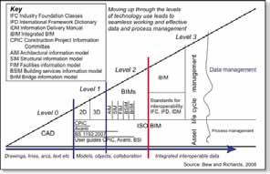
are bound together by alternative forms o f agreement that require team members to share risk and reward, contribute equally, and employ alternative processes and technologies (17).
The Macleamy Curve visually represents the shift in timing and classification of design phases (Fig. 2). The single most important change with IPD processes is the forward shift of work volume to earlier stages of design. The IPD process leverages early contributions of knowledge and expertise through utilization of new technologies, expanding the value each discipline with the design team provide throughout the project lifecycle. The outcome is the opportunity to design, build, and operate as efficiently as possible. The AIA describe the new process as: “Building upon early contributions of individual expertise, these teams are guided by principles of trust, transparent processes, effective collaboration, open information sharing, team success tied to project success, shared risk and reward, value-based decision making, and utilization of full technological capabilities and support” (18).
Much has been written about the apparent benefits of BIM and the IPD process, including findings from previous research efforts on live projects, observed benefits are fewer change orders (70.3%), cost savings (70.3%), and shorter schedule
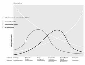
(69.4%)” (25). Eastman et al. (4) organized the benefits of BIM utilisation into four categories: preconstruction benefits (concept and feasibility), design benefits (visualization, auto correction of changes, 2-D plan generation, etc.), construction and fabrication benefits (synchronized planning, clash detection, automated fabrication, quantity survey and estimating, etc.), and post-construction benefits (facilities management and building operations). Based on such benefits of the widespread adoption of BIM, the initial estimated savings to UK construction and its clients is £2bn per annum. This means that it is a significant tool for UK Government to reach its target of 15-20% savings on the costs of capital projects by 2015 ( 26; 27). The news of the reported benefits along with the scheduled requirement of utilising Level 2 BIM on all UK Government public projects by 2016 ( 28) has resulted in a BIM boom within the AEC industry, resulting in the UK being recognised by its peers as one of the leading nations in the exploitation of BIM technology and processes with an internationally respected centrally-led programme (29).
Despite the leading edge of the industry pushing the frontiers of BIM exploitation, the majority of businesses are still developing capability in this area. According to the National Building Specification BIM Survey in 2013 (30) only 39% of the UK construction industry were aware of, and are using BIM. The report also provides evidence, and that 89% of users (and 91% of non-users) accepted that BIM requires changes in their workflow, practices and procedures. The scenario is similar in the US, and despite several professional organisations supporting the advancement of IPD ( 18; 31), and prior research efforts demonstrating its benefits and challenges (32; 33; 21; 34), the number of projects using IPD remains small (24, 35). There are generally few guidelines that outline factors that contribute to the success of multidisciplinary IPD projects available (36) and the reliability, and validity of any findings to date are said to be suspect due to the inherent limitations of ethnography i n relation to sample size (16).
The evidence suggests that there are cultural barriers due to the unwillingness of the industry disciplines to vary from its traditional own narrow leadership and methods that it is accustomed to. The challenge is overcoming the inertia and changing the mind-set built on this traditional hierarchy (37; 6). Research by Rooke, Seymour and Fellow (38) found this was the case in practices embedded within the UK construction industry as they observed a culture of exploiting mistakes in the bidding documents, scheduling work to maximize
delay impact, and proactive/reactive claims. They also propose that while these tactics harm the industry by hindering competitiveness, and decreasing efficiency, the practices have become an integral part of the culture of the UK construction industry and cannot be easily changed.
The move from 2D CAD to BIM is demonstrated in the BIM Maturity diagram (fig 1), but does not convey the fundamental changes that will be required to the AEC industry. The shift from level 0 BIM to level 1 BIM has been compared to the shift from drafting on tracing paper to CAD (39) However, the reality is that the outputs of issuing of 2D drawings on paper/PDF files, is still commonplace or an “electronic replica” . In stark contrast, the shift from level 0 to level 2 BIM requires: collaborative and integrated working methods; teamwork with closer ties between all designers on a project (39); increased decision density at early project stages; an obligation to produce deliverables for future BIM processes not associated with their normal duties; and work under different contractual agreements. With IPD a relatively new concept and not yet widely accepted within the industry (24), one of the greater industry challenges is the need to embrace new working methods and leave behind some old assumptions and stereotypes (39) and the capacity of participants to adjust to new work behaviours is critical to project success (18).
Smith et al (40) identified three areas for future research with respect to IPD: Environment; Organization; and Technology. More specifically, they identify the characteristics of the physical environment including the social, cultural, and behavioural context Ghassemi and Becerik-Gerber (37) also identified cultural (trust and teamwork), and technological (interoperability between participants) as major industry barriers to the transition from traditional processes. Literature review by Ilozor and Kelly (17) stated that there is a lack of thorough quantitative analysis and rigorous independent verification of the many qualitative assertions made within the literature with respect to IPD‟s potential positive impact on productivity, cost, schedule, quality, etc.
The purpose of this paper is to focus on an underlying problem facing AEC practices: despite the wide coverage of the perceived benefits of adopting BIM protocols, processes and investing in associated software, to date there has been a lack of case studies on live projects to act as evidence of the benefits of making the transition from traditional processes. The paper uses two international, 48 -hour BIM competitions as case studies to compare outputs and performance between a traditional design process and an integrated project delivery process. It should be noted that this paper is describing IPD in terms of a collocated,
collaborative process, rather than a contractual, formal way of working as set out within in the AIA, IPD Guide (18).
The research project uses two international BIM competitions as case studies: Build London Live 2011 (BLL) (see Fig.3); and Build Qatar Live 2012 (BQL) (see Fig. 4). Both competitions were organised by A-Site, a software for information sharing, and held over 48 hours (GMT). Details of the projects can be found in Table 1. Both competitions are based on a fictitious project brief, which is provided to participating teams 24 hours prior to the competition start time. Each team may consist of a range of AEC disciplines and are challenged to complete the brief objectives within the limited time period. All correspondence and completed work is uploaded to a password restricted project portal provided by competition sponsors ASite and judged by an independent panel of BIM experts. Teams are awarded prizes in a range of categories: best use of: BIM for design drama and excitement; multidisciplinary BIM and use of interoperability; BIM for sustainability or constructability; as well as overall BIM effort. (41). A team representing BIM Academy, consisting o f a number of design disciplines entered both competitions (see Tables 1 & 2). Data for this study was collated through observations from the authors who participated in both competitions. This was supplemented with documentation produced throughout the process.
Fig.4: Build Qatar Live 2012 Final External Perspective
Table 1: BLL and BQL project details
BIM Group BLL BQL
Site London, England Katuma, UAE Stage
RIBA: B 27 Nov 2012
RIBA: E
Table 2: BIM Academy team roles for BLL and BQL
Role BLL BQL
BIM Coordinator BIM Academy BIM Academy Architect
Structural
M&E
Cost Management
Specification
Visualisation
Validation
Landscape
Pedestrian Modelling
Ryder Shed
Fulcro
Turner & Townsend
BIM Academy
VNG
Northumbria
STEPS
Cundall
Turner & Townsend
NBS
VNG
Northumbria


Colour-UDL
STEPS
As the case studies used are competition projects, judged over limited design stages with no contractual agreements in place, there are obvious limitations to the findings. However, quantitative data from BLL and BQL can be used to make comparisons on a number of the suggested benefits from current BIM and IPD literature This includes comparisons of: (a) physical project environment; project management and technical characteristics of data sharing, between the projects, as suggested by Smith et al. (40); (b) programme accuracy, showing the results of the iterations, or change orders, in the design process; (c) the project
management through comparison of planning and decision making processes; and (d) number of outcomes delivered, can also be used to compare the case studies.
Both projects use the records of the BIM Execution Plan (BEP) that outlines the initial project management and programme to allow comparison of the level of accuracy in project delivery. The recorded number and times of outcomes being uploaded to A-Site by the teams are also used for comparison. The number of change orders, or iterations, in the design process is graphically represented using a Gantt chart method used in previous research efforts ( 42) (see Fig.5). This method also displays evidence for project programme accuracy and numbers of outputs. Finally, workflow diagrams will represent the differences in the physical and technological environment used in both projects. Table 3 summarises the findings comparison methods.
Higher levels of iteration expected along process
Medium levels of iteration
(ARC: Architect, SE: Structural Engineer; M&E: Mechanical and Electrical Engineer; QS: Cost Management; SPE: Specification; VAL: Validation; BIMA: BIM Academy Co-ordination)
Tight bandwidth expected with minor backtracking expected as all projects are unique
Fig. 6 shows the differences in physical environment and technological communication between the two projects. BLL has various disciplines working in separate locations, with Asite and emails the pri mary communication method used. BQL utilises design team colocation allowing an increase of informal face-to-face communication and ad-hoc input from all disciplines throughout the design process.
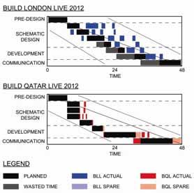
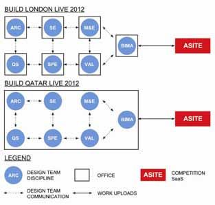
b) Programme and Accuracy
Table
Research Area Presentation Method
Project Environment
Communications Programme
Project Management
Outcomes
Diagram
Diagram
BEP, Gantt Charts
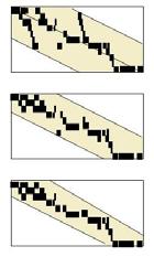
BEP, Diagram
Asite Uploads, Awards
a) Project Environment and Communication Methods
The analysis of project programmes is displayed in Fig. 7 presents a graphical representation of the case studies project activities through a Gantt chart as used by Macmillan et al. (42). The results clearly show how the BQL process was followed more accurately to BLL. The differences in BEP, physical environment and communication methods appear to influence the number of iterations in the process. This suggests a project adopting an IPD process (BQL) has a tighter „bandwidth‟ to projects using a traditional approach (BLL).
The results also suggest that due to the efficiency improvements in adopting an IPD approach, it was possible for the team to produce additional deliverables and uploads to Asite. It should be noted that the BIM Academy team produced 821 uploads, in comparison to approximately 200 per competing team (41). Despite it not being possible to compare competing team approaches, it suggests that an IPD approach influences productivity levels.
Fig. 8 shows that the levels of design effort against time are similar to that expected according to the Macleamy Curve. It could be argued that BQL would save costs due to reduced number of decisions being made in the latter stages of the project. BLL shows a steady increase in workload and decision making as the disciplines within the tea m brings their silos of work together at design development stage. BQL places more emphasis on collaborative working at the pre-design and schematic design stages respectfully This allows the majority of the deliverables to be completed during the design development stage, with the communication stages being utilised to make refinements and produce additional work beyond what was planned in the BEP. In summary, this leads to a smoother conclusion to the project. The findings support the analysis of the BEP and project programmes as the number of iterations in BLL are represented in increased efforts at the latter stages of the project.
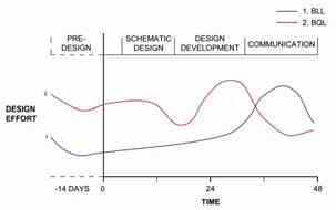
Table 4 shows the number of deliverables in the BLL and BQL projects. The results suggest that the planned outcomes were completed for both projects; however, there is a significant increase in deliverables in BQL as well as being more evenly distributed across the duration of the competition.
The significant difference in project performance between BLL and BQL was also recognised by the competition judging panel. BLL received an award for Best Use of BIM for Interoperability. BQL received the overall award, the openBIM Best Overall BIM Effort.
There have been various Government measures introduced to implement BIM and IPD processes in order to tackle the inefficiencies of the construction industry. Despite the perceived benefits and the UK leading international research, there is evidence of barriers in moving from the traditional AEC processes. This paper uses two international BIM competitions as case studies: one using a traditional design process and one integrated project delivery, in order to provide evidence to AEC professionals on a number of issues raised in the current BIM and IPD literature.
By comparing aspects of the case studies in the following areas: (a) project environment and communication; (b) programme and acc uracy; (c) project management; and (d) project outcomes, the findings suggest several themes. Despite the limitations of the case studies due to the absence of contractual agreements and reduced project stages, the findings suggest a number of themes, which, as explored in the results section show that the IPD process increases the programme accuracy, reduces the work load at the end of a project and increases the number of outputs.
Firstly, it appears that colocation of the design team in the same physical environment has an influence on the levels of communication between design disciplines. This results in tacit knowledge transfer and rapid decision making, allowing the project team to develop the design with reduced levels of iteration. Secondly, the project adopting an IPD process meant that they followed the project programme more accurately leading to fewer design iterations and a tighter „bandwidth‟. Thirdly, the project management of the process supported the theory of the Macleamy Curve, with the I PD process utilising higher levels of design effort at the early stages of the project. Finally, the IPD process resulted in an increased number of project deliverables being completed and being more evenly spread across the project‟s duration. The BQL project adopting the IPD process also achieved the highest award available in comparison to BLL project that used a traditional approach. Future work is recommended in testing similar aspects covered in this paper on live construction projects.
[1] HM Government, (2012) Building Information Modelling. Industrial strategy: government and industry in partnership, [Online] https://www.gov.uk/government/uploads/syste m/uploads/attachment_data/file/34710/121327-building-information-modelling.pdf
Accessed 1st May 2013
[2] U.S. Department of Commerce, Bureau of Economic Analysis (2010). Gross Output by Industry, Release Date: December 14, 2010. Retrieved from http://www.bea.gov/iTable/iTable.cfm?ReqID= 5&step=1 on 2nd May 2013.
[3] Teicholz, P. (2004) Labor Productivity Declines in the Construction Industry: Causes and Remedies, AEC bytes Viewpoints. Retrieved from http://www.aecbytes.com/viewpoint/2004/issue _4.html on May 2, 2013
[4] Eastman, C.A., Teicholz, P., Sacks, R., and Liston, K. (2008). BIM handbo ok: a guide to building information modeling for owners, managers, designers, engineers, and contractors. Hoboken, NJ: Wiley
[5] Pelburg, B.E. (2009) Contracting for Integrated Project Delivery: ConsensusDocs, presented at The 48th Annual Meeting of Invited Attorneys, Victor O. Schinnerer & Company, Inc.
[6] Lichtig, W.A. (2006) The Integrated Agreement for Lean Project Delivery Construction Lawyer 26 (3)
[7] Kieran, S. and Timberlake, J. (2004) Refabricating Architecture, New York: McGraw-Hill
[8] Gallaher, M.P., O‟Connor, A.C., Dettbarn, J.L., and Gilday, L.T. (2004). Cost Analysis of Inadequate Interoperability in the U.S. Capital Facilities Industry. [Online] http://www.fire.nist.gov/bfrlpubs/build04/art02 2.html accessed on 4th June
[10] Horman, M. and Kenley, R. (2005) „Quantifying Levels of Waste Time in Construction with MetaAnalysis‟. Journal of Construction and Engineering Management. Vol. 131(1), pp. 52-61
[11] Ireland, V. (1995) The T40 project: process reengineering in construction, Australian Project Manager, AIPM, 14 (5) pp. 31-37
[12] Han, S. H., Kim, D. Y., & Kim, H., 2008. Twostaged Early Cost Estimation for Highway Construction Projects. Report (2008), Civil & Environmental Engineering, Yonsei University, Seoul, Korea.
[13] Jergeas, G. F., Chishty, M. S. and Leitner, M. J. 2000. “Construction Productivity: A Survey of Industry Practices. 2000” AACE International Transactions, PM.06:01 –07.
[14] Naoum, Shamil G. "Critical analysis of time and cost of management and traditional contracts." Journal of Construction Engineering and Management 120.4 (1994): 687 -705.
[15] Koskela, L. (1992) Application of the New Production Philosophy to Construction. Technical Report No. 72, CIFE, Stanford University
[16] BIS (2012) BICS Economic Paper No. 18, Industrial Strategy: UK Sector Analysis, September 2012 [Online] Available at: http://www.bis.gov.uk/assets/BISCore/economi cs-and-statistics/docs/I/12-1140-industrialstrategy-uk-sector-analysis.pdf) Accessed 1st May 2013)
[17] Ilozor, B. D. and Kelly, D. J. (2012) Building Information Modeling and Integrated Project Delivery in the Commercial Construction Industry: A Conceptual Study, Journal of Engineering, Project and Production Management
[18] American Institute of Architects and AIA California Council (2007). Integrated Project
Delivery: A Guide. Retrieved from http://www.aia.org/contractdocs/AIAS077630 on May 1, 2013.
[19] Autodesk White Paper (2008) Improving Building Industry Results through Integrated Practice. [Online] http://images.autodesk.com/adsk/files/bim_and _ipd_whitepaper.pdf
[21] Cohen, J. (2010) Integrated Project Delivery: Case Studies, The American Institute of Architects, California Council in partnership with AIA [Online] http://hga.com/sites/default/files/downloads/res ources/ipd_casestudies_aiacc_final_010410_0. pdf Accessed on: 2nd May 2013
[22] Egan, John. "Accelerating change." A Report by Strategic Forum for Construction, London. 2002.
[23] BIM Task Group (2013a) PAS1192 -2
Overview [Online] Available at: http://www.bimtaskgroup.org/pas11922overview/ Accessed 10th May 2013
[24] Sinclair, D. (2012). BIM Overlay to the RIBA Outline Plan of Work, London, United Kingdom: RIBA
[25] Kent, D.C. and Becerik-Gerber, B. (2010). Understanding Construction Industry Experience and Attitudes Toward Integrated Project Delivery, Journal of Construction Engineering and Management, 136(8), 815825. doi:10.1061(ASCE)CO.19437862.0000188
[26] Wix, J. and Nisbet, N. (2008) Study into the Business Case for Interoperable Building Information Modelling (BIM), internal DTI report 2008)
[27] Cabinet Office (2011) Government Construction Strategy [Online] https://www.gov.uk/government/uploads/syste m/uploads/attachment_data/file/61152/Govern ment-Construction-Strategy_0.pdf Accessed 7th June 2013
[28] BIM Task Group (2013b) About Us [Online] Available at: http://www.bimtaskgroup.org/about/ Accessed 7th June 2013
[29] Bernstein, P. G. (2012) BuildingSmart Qatar BIM Summit, October 2012
[30] NBS (2013) National BIM Report 2013
[31] AGC (2009) Integrated Project Delivery for Public and Private Owners. NASF, COAA, APPA, AGC, AIA White paper on IPD, AGC
Publication 40 [Online] http://www.agc.org/galleries/projectd/IPD%20f or%20Public%20and%20Private%200wners.pd f Accessed on 3rd June 2013
[32] Matthews, O., and Howell, G. (2005) “Integrated Project Delivery: ConsensusDocs, presented at The 48th Annual Meeting of Invited Attorneys, Victor O. Schinnerer and Company, Inc.
[33] Hellmund, A., Den Wymelenberg, K. and Baker, K. (2008) “Facing the Challenges of Integrated Design and project Delivery
[34] Becerik-Gerber, B., and Kensak, K. (2010). Building Information Modeling in Architecture, Engineering, and Construction: Emerging Research Directions and Trends. Journal of Professional Issues in Engineering Education and Practice, 136(3), pp. 139-147
[35] Sive, T. (2009) „Integrated Project Delivery: Reality and Promise, A Strategist‟s Guide to Understanding and Marketing IPD‟, Society for Marketing Professional Services Foundation White Paper on IPD, SMPS Publication 21
[36] Ghassemi, R. and Becerik-Gerber, B. (2011). Transitioning to Integrated Project Delivery: Potential Barriers and Lessons Learned. Lean Construction Journal, 2011, 32-52. [Online]http://www.leanconstructionjournal.org
Accessed on 11th May 2013
[37] American Institute of Architects and AIA California Council (2007). Integrated Project Delivery: A Guide.[Online] http://www.aia.org/contractdocs/ AIAS077630
Accessed on 4th June
[38] Rooke, J., Seymour, D., Fellow, R. (2004). Planning for Claims, an Ethnography of Industry Culture. Construction Management and Economics, 22, 655-662.
[39] RIBA (2012) BIM Overlay to the RIBA Outline Plan of Work
[40] Smith, R.E., Mossman, A. and Emmitt, S. (2011). Editorial: Lean and Integrated Project Delivery Special Issue, Lean Construction Journal, 01-16. Retrieved from http://www.leanconstruction.org/media/docs/lcj /2011/LCJ_11_sp1.pdf on May 14, 2013
[41] Build Qatar Live (2013) Awards [Online]
Available at: http://www.buildqatarlive.com/index.php/a wards Accessed on 28th July
[42] Macmillan, S., Steele, J., Kirby, P., Spence, R. & Austin, S. (2002) Mapping the design process during the conceptual phase of building
projects. Engineering, Construction and Architectural Management (9) 3, pp. 174-180
Construction Sector Team, London
E-mail: 1john.hunt@enterprise-ireland.com
Evidence and findings from a pilot study to better integrate the supply chain into the evolving information needs of their client base. Could the industry adoption of BIM be accelerated through heightened involvement of the product manufactures and suppliers? Six manufacturing companies provide an evidence based rationale that a strategic (rather than organic) approach to their implementation will provide the efficiencies necessary to support a wider industry adoption of BIM.
Keywords BIM for Manufacturers, Tier 2+3, Strategic Implementation, SME challenges
In March this year Enterprise Ireland commissioned its first BIM training programme for Irish construction sector clients following on from a lengthy period of appraisal. A key conclusion of our initial research was that an accurate design model and a broad supply base are fundamental requirements for the efficient delivery of an asset. The absence of the specialist and the product supplier in the creation of the model is a missing link or ‘knowledge gap’ in the path of the industry’s digital evolution. Similarly, a reactive approach of the supply chain beyond tier one will restrict choice and potentially increase the cost and inefficiency of those suppliers who are forced to implement BIM in short timescales.
Since 2010 Enterprise Ireland have been researching the potential of BIM and the opportunity presented by BIM for the construction sector with interests in overseas markets. Would BIM be an enabler of design consortia in the Middle East? Was it a must have just for design professionals in the UK working on high density serviced buildings or complex rail infrastructure? Ultimately, could an early commitment to BIM provide competitive advantage and how sustainable was that advantage?
Like everyone else we needed to understand whether BIM would be mainstream and by when? What does successful BIM implementation look like in 2020 –25% of projects – 50% of projects? By way of a comparison offsite construction has struggled to get beyond 6-7% of total industry spend in the UK. If total public capital spending in construction runs at circa £40 billion p.a. in real terms to 2020 what percentage of this spend is affected by the central government mandate and what proportion is investment in UK infrastructure (roads, rail, power) and what proportion is in buildings. The Government mandate is at the very least an enabler to facilitate change, but it is the convergence of technology that really opened our eyes to the true potential –Increasingly, closing the design/performance gap, improving sustainability and the efficient management of building assets each become key outputs of BIM if we can implement widely and efficiently.
We also conducted an independent industry consultation across a sample group of UK designers and contractors engaged with BIM to better understand their current and projected information needs.
84% of the sample’s current BIM information needs were poorly supported by their supply chains and
How accurate is the model? The integration of products and services into the information needs of designers and contractors.
76% of the sample group were concerned about their supplier’s ability to provide product information in the form required for Level 2 BIM. Other common needs were articulated as follows:
“ We need suppliers who understand BIM workflows and standards and provide usable modelling objects”…..”Designers want quality assured information and supplier capabilities as they take accountability if they use 3rd party information”….”There is potential to gain competitive advantage through good reliable provision of BIM information.”
The question ‘How do we do BIM?’ at a macro level, as an industry, has been the starting point for many individual companies in understanding ‘How do we do BIM?’ at a micro level. The reality for the companies we have worked with, particularly across manufacturers and specialist suppliers, is that their individual BIM implementation programmes vary enormously. What they all shared was a level of concern about deeper and earlier engagement; that they could see little incentive for being first and they struggled to make a business case or to divert their constrained resources to invest now.
From our research, “how we do BIM” at an industry or at an individual level, supports the critical importance of engaging the SME supply chain if BIM is ever to break into the mainstream.
In the context of the current procurement process, yes, BIM may well present more supply chain risk by engaging more deeply at the specification level. Yes, you could lose your design application IP in repeat format models. Yes, it may well create higher barriers to entry for other suppliers once you’re on the model, but the opposite may also be true. Will the value of specialists become greater to main contractors leading to a deepening of the supply chain relationship or is this a short term phenomenon until they can source more broadly?
In the context of future procurement processes, the need for new forms of contract that reflect the need for interdependency and collaboration is as a minimum widely recognised and in the case of Surrey County Council who are exploring two stage open book tenders and more collaborative forms of contract, the potential for progress is encouraging.
What I restate at this juncture, is the need for manufacturers and specialists to understand the risks, to see the potential for a broader change and engage early if we are to provide accurate models. This current ‘gap’ between the design model and the level and quality of detail a contractor needs (to avoid the generation of ‘another model’) we currently refer to as the ‘Knowledge Gap’.; a void that is exacerbated by the use of generic objects, generic performance schedules and general specification.
The Construction Industry Council (CIC) working group target at Data Drop 2 (RIBA stage 3) is for the accuracy of information incorporated to be between 75-80% with a tolerance of +/- 20%-25%. In all likelihood, it is anticipated that Data Drop 2 will become 2a and 2b and the journey and information requirements from 2b to 3 will also require a significant involvement in validating and building a coordinated accurate representation. At Data Drop 3 (RIBA Stage 4) accuracy of the model is expected to be 85-90%. Here the model represents a fully coordinated technical solution that can be built with all input from the contractor incorporated.
There is plenty of evidence in other markets and jurisdictions where BIM has been engaged as a design tool or as a construction management tool. But the engagement and delivery of a broad supply chain supporting BIM is a far rarer animal and we as an industry are at a very early stage.
We concluded as investors and supporters of industry that there is a significant opportunity for companies that could meet a set criteria – The greatest opportunity in terms of timing lies within those companies that simplify the model, at design and construct and have the application expertise and installation capability to become a trusted and long term partner with designers and contractors alike. They are the specialists that can take a modelled package of works from generic levels of detail to 90% accuracy and that can best simplify the interfaces of the Integrated Project Delivery process through simplification of the packages managed by the contractor.
The selection criteria of companies with the ‘most to gain’ and the ‘least to loose’ resulted in a group of companies that had offsite design and manufacturing capability and the capacity to install their products. Two façade manufacturers, two structural systems manufacturers and two civil engineering system manufacturers were selected.
The design of our programme to engage with these SMEs began with the agreement of our 3 golden rules. Whatever we present, however the programme is structured it must be sympathetic to three key SME business drivers:
a) Does it help to win work, and when?
b) Does it help us to get paid?
c) Does it consider our constrained resources?
Ultimately a seven stage programme was developed and delivered that engaged and worked across all functions of each business. Three Sessions were in workshop environments and four sessions were conducted at the companies manufacturing operations to understand individual starting points, implementation needs and constraints.
(To be presented through case study)
Practical examples of the high risk and high cost of an organic approach (waiting to be asked) to implementing BIM.
The LEAN benefits of developing BIM objects that meet external needs and capture internal requirements for logistics and manufacture.
The concept of LEAN object development
Understand the information needs and the implications for your business process across the RIBA stages and the Data Drops.
Working with models and supporting clients across different software platforms.
Without an accurate design model, without a broad supply chain that can validate the accuracy of the model, BIM will require considerable rework and contain inherent inefficiency. Anecdotally, this is the message that comes from project teams and construction sites now. The BIM projects today are examples of learning and not of improved efficiency. PDF drawings extracted from models and sent to suppliers are holding back the efficiencies available through BIM that have to be realised if we are to drive construction forward.
We must work with the supply chain to better inform and advise how risk can be managed and how opportunities may arise. Ultimately the current forms of procurement present inherent risk that may constitute a lack of choice in supply that as a result may out weigh the efficiencies presented by BIM. Other inhibitors and areas for further research include the appropriateness of software to the needs of the supply chain and the availability of training to develop a non cost prohibitive in house object creation capability. The key recommendation from our review however, would be for the terms of engagement for key packages and for key suppliers to be redefined, reprioritised and explored in far greater depth to truly enable BIM.
We continue our work on building capability in the supply chain to support the success of BIM and would be pleased to speak with all potential contributors and collaborators that are looking to better manage, understand and broaden their supply chains.
Department of Building and Civil Engineering
Galway-Mayo Institute of Technology, Dublin Road, Galway
E-mail: 1gerard.nicholson@rpsgroup.com 2 jim.oconnor@gmit.ie 3patrick.tobin@gmit.ie
Abstract
Purpose – In recent years the application of Building Informati on Modelling (BIM ) in many countries has been increasing because of its ability to optimise and manage the construction proc ess. The purpose of the studies presented in this paper are to investigate the feasibi lity and applicability of BIM for delivering value on small sized (i.e. €1-2 million) construction projects.
Methodology– A case study was conducted on a new ambulance ba se that was being constructed in Tuam, Co. Galway. The study began during the implementation stage of the construction processes and ran in parallel to the actual construction. The benefits that each of the different dimensions of BIM (i.e.3D to 7D) could have had if BIM were implemented on this project are discussed here. Using examples from this study we have (1) highlighted the benefits of BIM as a communication tool in relation to 3D BIM, (2) its ability to improve the quality of the construction docume nts and the quality of design in relation to 4D BIM , (3) it’s advantages as a material and cost estimator and its uses in relation to performing energy analyses (5D and 6D BIM). (4) We have also discussed the advantages that the 7th dimension of BIM . In addition to this we have analysed the advantages of the BIM process as a whole. To do this we have made comparisons between communication and information availability, the ability to adhere to projected time schedules and the ability to meet projected cost estimations and profit margins.
Findings –We have found that there is an increased understanding of design intent by both the clients and the different disciplines within the construction team. In a number of cases we have also found that BIM could have increased the quality of the construction documents, the quality of collaboration between the different disciplines and the quality of the finished product. In this study we have found the accuracy of the material estimates made by BIM are within 1%. We have found that using 6D BIM can prevent errors relating to the failure of building elements to meet requirements and in relation to 7D BIM we have found that it is a more rapid and reliable means of producing a safety file.
From analysing the BIM process as a whole we have found that using BIM can increase information availability and on this case study it could have reduced the amount of communications made between the design and construction teams and thus could have reduced construction delays. If BIM were implemented here it could have made a 7% saving on the construction time and it could have made a 1.4% of cost saving at the implementation stage.
Practical implications – This research documents both the quantitative and the qualitative benefits of BIM , we present the benefits of the BIM processes when used on Irish construction projects and recommend alternatives to the traditional project management processes . This information is useful to Irish construction industry practitioners considering a pplying BIM to their projects.
Keywords BIM, Building information modelling, small scale construction projects, parallel study
Thirty years of two dimensional and three dimensional developments have contributed to the production of the Building Information modelling (BIM) process 1. The BIM concept has been around since the 1970’s 2 , the term first appeared in a paper by Van Nederveen et al. in 1992, however until Autodesk released a paper entitled “Building Information Modelling” the term wa s relatively Unknown3 Construction vendors had a big part to play in the spreading of this term and it is now widespread throughout the industry4. BIM is known by many other names in the industry such as virtual
building5 and integrated project modelling6 however BIM remains the most popular name The definition of BIM, as stated by National Institution of Building Sciences (NIBS) is:
“... a shared knowledge resource for information about a facility forming a reliable basis for decisions during its life-cycle; defined as existing from earliest conception to demolition. A basic premise of BIM is collaboration by different stakeholders at different phases of the life cycle of a facility to insert, extract, update or modify information in the BIM to support and reflect the roles of that stakeholder7”
BIM is a new trend in the construction industry and for many professionals within this industry it is a new way of thinking and new process of working. There has been some usage of BIM in the Irish construction sector; a royal institute of the architects of Ireland (RIAI) survey conducted in 2011 has reported that the adoption of BIM in Ireland has reached 17%8 Well known construction projects that have utilised the BIM process include the Aviva Stadium9 and the New Children’s Hospital of Ireland10
Generally, the construction sector has a history of moving slow with technology compared to other industries. The same can be said in relation to 3D technology; the fact that architects, engineers and other professionals are still using 2D drawings that have no relationship to one another indicates that the sector is ‘behind the times’11
Inefficient sharing of information and inefficient collaboration throughout the lifecycle of a building are major problems in international construction practices. A solution to this is to alter construction practices so that more efficient information flow and greater collaboration can occur between team members (i.e. design consultants, main contractors and specialist sub-contractors) Ideally, this change should begin during the early design stages with the adoption of integrated project delivery (IPD). IPD is a multidisciplinary approach which involves the design, construction and maintenance processes. BIM offers significant opportunities for revolutionising the sector as it enables the processes that support the complete building lifecycle to run seamlessly12
Here Denmark, Finland and the UK have recently begun to introduce national initiatives to drive BIM implementation forward. They have done this by making the use of BIM on the procurement of public projects mandatory. The aim of these incentives is to promote BIM and to encourage industry-wide adoption13
BIM is primarily understood to be a 3D parametric tool that is used to facilitate the design phase of a construction project however it can have a wide range of functions including: facilitating information sharing between various stakeholders on a project; enabling the use and management of shared ‘meaningful’ building infor mation; facilitating the simulation of construction processes, enabling environmental and energy analysis; and supporting emergency response operations12
There are a number of areas where using BIM can be advantageous;
Firstly, stakeholders involved in a development may not have had experience working in the construction sector before and in such cases 2D drawings just don’t give the same impact as 3D visualizations14. As Napoleon Bonaparte famously said “A picture is worth a thousand words” and conveying a complex idea or design to a client in 3D
format is a more efficient process and can reduce unnecessary changes to the construction project11
Another major advantage of using BIM in the construction industry is its ability to accurately measure and calculate energy requirements and building performance from the virtual model before the actual construction work commences. This is important as “The most effective decisions related to sustainable design of a building are made in the early design and preconstruction stages”18. Traditional CAD planning environments do not support the possibility of such early decisions. Energy and performance analysis are typically performed, if at all, after the architectural design and construction documents have been produced. This lack of integration into the design process leads to an inefficient process of retroactively modifying the design to achieve a set of performance criteria 19 BIM can also serve as a tool to reduce the amount of waste produced during a construction project. It is estimated that, typically there is an average of over 25% waste in all construction projects20. It is predicted that by using BIM, this figure can be reduced to single digits
7D BIM is used to compile and manage the operations and maintenance information of the building, BIM presents a visually precise three dimensional building system and a softcopy database for recorded information associated with the buildings elements31 Using BIM to compile this information is advantageous as there is increased accuracy of information, reduction in the amount of time taken to compile the data and an increased accessibility of the information.
Finally, many of the practices used in the construction sector have problems; such problems can be minimized or solved by using good project management and BIM. The greatest stakeholder to benefit from the BIM application is the client; the client’s objectives are the most important and by using BIM as a project management tool it achieves less time on-site, less overall cost and produces a higher quality construction project21
BIM will achieve success for the Irish construction sector if it is used in conjunction with good project management, however currently not all aspects of BIM are being utilised and thus not all benefits from the model are being achieved 8. It is the author’s belief that BIM will be the next major advance in the construction sector; it is not just a software package but a new way of working collaboratively. BIM proj ects will change the traditional delivery system improving the way we manage, communicate, plan and work together.
There are many different ways in which the BIM process can be used on a project. Most writers
describe these different ways in terms of 'dime nsions', from 3D to 7D. As the model gains more dimensions more new data is added, there are new dimensions of BIM being created all the time. The applications of the 3rd to the 7th dimensions of BIM are discussed below.
BIM was more accurate than conventional methods. By directly linking BIM to a cost estimating data base, engineers reported time savings of 80% and an accuracy of detailed estimates to 3%28.
3D
Modelling - involves the development of design drawings or fabrication drawings within a BIM environment. The three dimensional model is one of the most important parts of the model as all others aspects of BIM feed off this model. Photorealistic computer renderings can be created from the BIM model with the use of visualisation specialists22. 3D walkthroughs are created to simulate a first person view, walking around the building can communicate to various ranges of stakeholders23. The design team can use 3D models to communicate complex designs at meetings that could not otherwise be conveyed in the traditional 2D drawings 24. Hartmann et al. (2008) carried out a study on 3D application on a construction project and found that communication was significantly improved with the use of visualizations to design team and public.
6D – Environmental Analysis. There is a major need for change in the construction industry with regard to producing more sustainable buildings. It has been well documented that sustainable analysis with the use of BIM at the design stage has many advantages over traditional 2D drawings30. BIM allows the users to analyse different designs with regard to orientation, climate, space heating, thermal values of building elements and energy strategies etc.
The most effective decisions that impact the sustainable design of the building are made at the early design and preconstruction stages. Early design analysis traditionally is not possible with the use of 2D geometry. BIM allows for the analysis of the building early on in the design and lowers the costs associated with an energy anal ysis.
4D
Phasing of construction project - uses the 3D model to simulate or animate the construction processes for the use in planning activities. The four dimensional model can also be used to find cla shes throughout the building and can eliminate all design errors. The project planners can simulate or animate the construction activities by linking the 3D model to tasks in their project management software 25. The 4D models can then be used to see parts of the construction at a particular time, simulate at certain times or walkthrough the building as the building is sequenced26. 4D BIM is also used for the management of the site during implementation stage, planning of site logistics, coordination of trades, access routing27. According to Hartmann et al. (2008) analysing construction operations is the most utilised aspect of 4D and 3D modelling when employed on a project Clash detection is the ability to find conflicts within a single model or between models and is se en as a collaboration and coordination tool. The inconsistencies between the models have been found to prevent severe impact errors on construction processes, delays, design changes, materials costs and budget overruns17. The clash detection and visual review of the building has been seen to reduce the schedule by 7% and reduce contract value by 10% 28 .
5D - Cost estimation - BIM can be used to produce a bill of quantities at any stage of the construction project and the model can then be linked to cost estimation software. The link between the cost estimation and BIM gives the user the ability to change the design and get cost estimation automatically29
Hartmann et al. (2008) have found from conducting a number of case studies that estimators reported a 25% reduction in estimating efforts and
7D - Facility’s management - BIM presents a visually precise three dimensional building system and a softcopy database for recorded information associated with the buildings elements31 The operation and maintenance costs of a building on average account for 60% to 80% of the life cycle costs of the building32. There is much more emphasis on the implementation stage and not enough on the operation stage33
BIM assembles the facility’s information in a structured and accurate way. The ConstructionOperations building information exchange (COBie), was developed in 2007 by NASA and the U.S. Army Corps of Engineers31 and in 2016 it will mandatory for every public building in the UK over £5 million to exchange life-cycle information in COBie format34 As the design-bid-build process does not have a fully integrated team the COBie process is limited.
Information is deposited from the model at a number of points throughout the construction process, this is also known as a data drop . The data drop that occurs at the closing of construction project contains information for the maintenance of the facility35. Data drops are outlined in the COBie UK process, clients can check on the status of the development against the briefs deliverables. There are two forms of BIM information; these are divided into graphical information and non- graphical information35 Graphical information is visualizations of the building either in 2D or 3D representations. Non- graphical information is the extraction of life cycle informat ion attached to building elements, documentation such as materials schedules, spaces, etc.
The aim of this research was to determine the value of using BIM on a small scale construction project. In order to do this, we carried out a study in parallel to a live construction project. The benefits that each of the different dimensions of BIM (i.e.3D to 7D) could have had if BIM were implemented on
this project are discussed here. Using examples from this study we have highlighted the benefits of (1) BIM as a communication tool in relation to 3D BIM, (2) its ability to improve the quality of the construction documents and the quality of design in relation to 4D BIM, (3) its advantages as a material and cost estimator and (4) its uses in relation to performing energy analyses. (5) We have also discussed the advantages that the 7th dimension of BIM could have had if it were implemented here.
In addition to this we have analysed the advantages of the BIM process as a whole. (6) To do this we have made comparisons between communication and information availability, (7) the ability to adhere to projected time schedules and (8) the ability to meet projected cost estimations and profit margins
The focus of the study involved applying BIM processes to projects (case studies) in parallel with the actual methods of managing the live projects One major study was undertaken in parallel with the implementation phase of a construction project. Two other minor studies were undertaken in the planning and design phases of other construction projects.
Some of the stakeholders had used BIM to some extent previously however they had not had much experience with it, others had not had any experience using BIM at all. There was no BIM application used on any of the cases before the study began. The benefits of the BIM process are analysed and mapped against the actual and/or the conventional recommended processes.
All three studies involved the development of virtual models using BIM software. The major study involved the use of BIM software to prepare a virtual model of the building, including structural model, mechanical & electrical model s, environmental analysis, creating a simulation of the construction works, clash detection information, quantity takeoff, and 3D presentation. Towards the end of the project a complete virtual “as built” model of the buil ding was updated and finalised.
The case study approach undertaken is essentially qualitative, even though some quantitative evidence of benefits is documented. The projects selected for study were proceeding with or without the research involvement. Thus, the research opportunity to 'track' the live progress for comparison purposes in the main example, and introduce BIM models for consideration in the two early stage examples, required a flexible approach. The data gathering opportunities available in the study included verbal observations, informal interviews, existing project documentation (e.g. plans, schedules, timesheets, invoices, etc) and attendance at project meetings.
The study focuses on understanding the processes and how the actions and outcomes could be influenced by BIM. Woodside (2010) suggest that "... deep understanding of the actors, interactions, sentiments and behaviours occurring for a specific process through time should be seen as the principal objective by the case study researcher." He also recommends that this deep understanding be achieved by directly observing in 'real ti me'.
The decision to use a qualitative research approach, and particularly case study examples, is based on the view that this research study is exploratory in nature. Kothari (2004) explains that where the major emphasis is on discovery of ideas and insights, the research design must be flexible and should permit the consideration of many different aspects of a situation.
Kothari contends that inbuilt flexibility in research design is needed in exploratory studies because the research problem, broadly defined initially, is transformed into one with more precise meaning in exploratory studies, which fact may necessitate changes in the research procedure for gathering relevant data. Kothari identifies analysis of ‘insight-stimulating’ examples or case studies as a fruitful method for research in areas where there is little experience to serve as a guide. "This method consists of the intensive study of selected instances of the phenomenon in which one is interested. For this purpose the existing records, if any, may be examined, the unstructured interviewing may take place, or so me other approach may be adopted. Attitude of the investigator, the intensity of the study and the ability of the researcher to draw together diverse information into a unified interpretation are the main features which make this method an appropriate proc edure for evoking insights." Kothari (2004)
In addressing the choice of examples to be studies, Kothari recommends that "cases that provide sharp contrasts or have striking features are considered relatively more useful while adopting this method of hypotheses formulation." The three cases chosen in this study are quite different in terms of the phase of development, the building function, and the stakeholders involved. This resulted in a wide variety of observations from each study. Gilham (2010) noted that "... for the case study researcher all evidence is of some value, and this value (trustworthiness) has to be carefully appraised." He described the central concern of the case study method as "the collection and study of multiple forms of evidence, in su fficient detail to achieve understanding." This is in keeping with Kothari (2004), " In an exploratory research study which leads to insights or hypotheses, whatever method or research design is adopted, the only thing essential is that it must continue to remain flexible so that many different facets of a problem may be considered as and when they arise and come to the notice of the researcher."
The variety of observations and insights in this study includes some quantitative data. Gilham (2010) points out that "For case study research operating in the real world, quantitative data analysis has to be subjected to the scrutiny of what it might meanwhether or not it is statistically significant. Even if the numbers involved don't yield a statistically significant difference, there may be important differences in reality and more subtle human terms." In this study, Gilham's comment is very relevant. Obviously, with one specific example statistical significance is not relevant. The quantitative data in this case shows that real cost savings could have been made if BIM techniques were used. However, this data can only really be referred to in terms of 'support' for the qualitative conclusions that BIM benefits the design and build 'process'.
Gilham claims that qualitative methods, such as the case study example technique employed here, "enable you to carry out research into the process leading to results rather than into the 'significance' of the results themselves". This ability to observe the process, and gain the deep understanding of the process and the effects of BIM on the process is what verified the choice of case study examples for this research study.
The main study of this research was conducted during the implementation stage of the con struction of a new ambulance base in Tuam, Co. Galway. This centre was being constructed in order to provide greater emergency coverage between Galway, Roscommon, Ballinasloe and Castlebar hospitals. The primary role for the facility is the response to emergency calls 24 hours per day for 7 days a week
The Ambulance base was cost estimated at less than €5 million and designed by the client . 3D, 4D, 5D and 7D models of the building were created (Fig. 1)
The 3D models were created to assess the difference between the BIM and traditional construction documents, these models were presented to the clients and the construction team.
4D BIM models were created according to the traditional construction documents and were used to carry out clash detection and interference checking The errors detected in the 2D construction documents while creating the BIM model and while performing interference checks were recorded and compared with a list of problems encountered onsite in order to quantitatively analyse the advantages of BIM.
A 5D material estimation was also made using the BIM software. Quantities of the major elements of the building – the blocks, the concrete and the structural rebar were determined. The accuracy of these estimations was then calculated by comparison with those estimations made by the construction team.
Finally a 7D BIM model was created; this involved compiling the operations and maintenance information of the building. The information was extracted from the 3D model and converted into COBie format.
From comparing the traditional process carried out onsite (and with the BIM enabled process under each of the dimensions outlined above a number of differences were observed, these differences are expressed quantitatively.
The 3D models of the Tuam ambulance base were displayed at a number of different presentations and from this the advantages of BIM as a communication tool were assessed.
The Tuam ambulance base 3D models were presented to the construction team and representatives of the clients From viewing 3D photomontage of the ambulance garage containing an ambulance one of the ambulance officers present was able to identify two design errors He noted that the mechanical exhaust system for the extraction of the ambulance exhaust fumes was not located in the right area. He also questioned the location of an ambulance charging unit which was not present on the design. As a result this two design changes were requested by the client
In light of this observation it is the author’s opinion that the 3D BIM models are an invaluable resource for communicating the design intent of a building. The ambulance officer was the user specific to the ambulance garage and as such, the design errors were more apparent to him, if the design had been presented to this stakeholder in 2D format it is less likely that he would have made the connection between the location of the ambulance exhausts and the mechanical extraction system as it can be difficult to form 3D mental images from a number of 2D drawings As the design was presented in a 3D format it was easier for him to associate the design error with the operational use of the space.
BIM is also very useful when communicating to not just to clients, but also to the public, funding agencies, target markets and to the design team. During our study 3D BIM models of a local school were created and used by the stakeholders involved as a marketing tool. These 3D images were published in 3 local papers in order to publicise the school The models and walkthroughs were described by the school principal as “…invaluable in communicating the size, scale and quality of the school building and facilities …”
A number of errors were identified in the traditional construction documents on the Tuam building while creating the BIM models, there were 15 drawing omissions 11 of which were due to a lack of a relationship between drawings from the different disciplines and 5 were as a result of missing information. 8 annotation errors were identified; these were all caused by a lack of coordination within the different disciplines There were also 13 coordination errors identified, 10 of which were hard clashes, 3 were clearance clashes. Two errors also occurred due to the misinterpretation of the construction documents.
In the author’s opinion, the 3D modelling process is a good way to visualise clashes that are going to occur. While creating the 3D model, it was found by the author ’s that clashes were easier to anticipate compared to drawing in 2D CAD, this was due to the ease at which the design is visualised. In addition to this, creating sections, elevations, plans, 3D views and schedules is much less repetitive and less challenging as all of the drawings are linked in the BIM environment. When a parameter is updated in one drawing it is automatically updated in all of the associated drawings, this reduces the human error associated with creating the drawings. Furthermore the clash detection analysis available from the 3D software provides a further means of identi fying and eliminating errors at the design stage.
Errors at the design stage reduce the quality of the construction documents, they reduce the quality of the coordination between the disciplines and they reduce the quality of the communication.
If BIM were used at the design stage on this project it could have increased the quality of the construction documents and thus increased the constructability of the building. There would have been an overall time saving and reduction in costs due to the avoidance o f unanticipated work and the
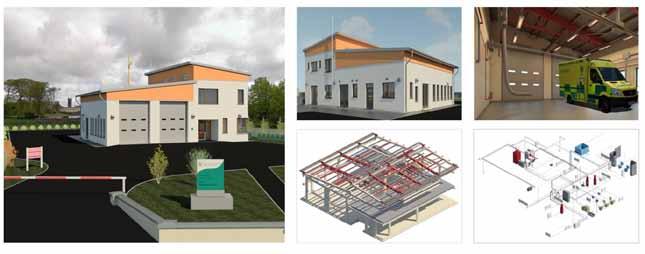
prevention of rework. Coordination errors identified during this study resulted in clashes between different elements onsite, in four cases this affected the operational use of the building. Clashes occurring also result in increased cost of the activity, this can be due to the need to do rework, other unanticipated work and also the increased labour costs associated with an the added amount of time spent on the activity. The quality of communication onsite was negatively affected by the lack of clarity of the 2D construction documents, on this project it resulted in two design misinterpretations Misinterpretations occur due to a lack of clarity in the construction drawings and from a lack of understanding by people who are unable to form 3D mental images from looking at multiple 2D drawings36 As the 3D BIM models are information rich and the design intent is clear the use of BIM at the design stage could have avoid many of the misinterpretations that occur between the design an d construction teams.
To analyse the accuracy of BIM at performing material estimates the authors have compared those generated from the BIM model with those produced by the Quantity Surveyor and the sub-contractor. It was chosen to compare the estimations made for the block work and the concrete for the raft as these are major elements of the building The block count produced by BIM was within 0.7% of the estimate made by the subcontractor and the amount of concrete estimated was within 1.0% of the quantity surveyors’ estimation
The accuracy of the material estimates found here are greater than those specified in current literature i.e. within 3%28, this difference however may be related to the small size of the project. From carrying out the cost estimation in BIM the author ’s has found a number of problems associat ed with the estimation software, the cost estimation varied depending on the way that the building was
modelled i.e. when creating the foundation in Revit, when using a ‘slab edge’ the estimation was inaccurate and when using an ‘in-place model ’ the estimation was within 1.0% of those made by the QS. The author ’s put this error down to a glitch in the software, as a result of this we propose that currently, this is not a reliable method for making estimations, but the software could serve as a checking system. Lee (2008)40 have also found similar limitations in the actual specific cost limitation software; they overcame this by cost estimating the project by a different method and using BIM estimates to support the precision of other estimates
Another advantage of using the 5D BIM estimation tool is that it can provide a means of cost control. The estimates from a BIM model are live and thus any updates to the model are automatically seen in the estimates. From a control costs and estimates point of view, the ability to link the BIM model to a cost data base14 could greatly increase cost information flow. Turner & Townsend Rawlinson have found that using cost estimation by linking BIM models to a cost data base can result in reduction of scope creep. Scope creep is reduced as a result of more accurate initial total cost estimations, the client is aware of all the costs and there is a reduced likelihood of later changes.
An energy analysis model of the Tuam
Ambulance Base was created using Autodesk Ecotect Analysis. This case study was undertaken in parallel at the implementation stage of the project; the impact of an energy analysis at this stage of a project is minimal as information relating to energy efficiency of a building is more valuable at the design stages of construction. However an observation was made which highlights the benefits of using the BIM energy analysis tools. Prior to the commencement of the works the environmental requirements of the building were specified as a BER rating of A3/B1. During the works a preliminary report stated that the planned garage doors did not meet the requirements, a change order had to made, adding an extra cost of €3108 to the project. A BIM model can hold information required for BER assessments and legislation requirements (room area, room volume, U -Value etc.) and if BIM were implemented at the design stage of the project this error could have been avoided The author ’s believe that the energy analysis capability of BIM can lead to better design confidence and more accurate end costs
In order to compare the quality of the operations and maintenance information between the traditional process and a BIM enabled process the authors have compared the quality of the as built drawings (i.e. the drawings that indicate what was actually built) and the process of creating the safety file. 12
Fig. 2 (i) A control chart documenting the total number of enquiries made per activity. The upper control limit (UCL) is set at 3σ limits from the mean (17.88), and the uppe r warning limit (UWL) is set at 2σ limits from the mean (13.37). The average number of interactions per activity is (4.34). One of the activities (6), exceeds the UWL and one of the activities (17), exceeds the UCL.
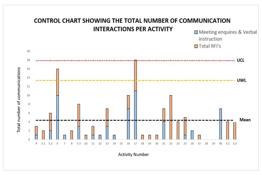
drawing errors were identified in the as-built drawings, all of which were as a result of failure to update the design drawings
A lack of accurate and valuable operational and maintenance information is a common problem that occurs during the closing out of a project, if the drawings are not regularly updated during the construction process there is a pile-up of paper work at the end of the project, in many cases at the end of the project there is a lack of motivation and the work is not carried out37 Zamia {2010} has shown that as-built information is much more accurate and valuable to the operation and maintenance of the building when BIM is used. If BIM were used on this project it could have avoided all of the as build errors that occurred. For example, in the safety file there were instances where the architect’s drawings were updated and the structural engineers were not, when updating in a BIM model the drawings are linked and thus when one is updated all of the related drawings are automatically updated. Also many of the errors found within the 2D construction documents when creating the BIM model had transferred to the as-built drawings; if the models were created in BIM at design stage the need to update the models would have been prevented.
The safety file for the Tuam ambulance base was compiled by the site manager on closing the project; it took three weeks to assemble all of the documents gathered throughout the project (verbal communication). The safety file was in paper format and is of considerable size. An electronic version of this file also had to be created for uploading to the online asset management system Zutec; this was a labour intensive process. When using BIM the safety file is compiled electronically, this process is very quick. The operations and maintenance data is instantly extracted into a COBie excel sheet, this information is also attached to an interactive 3D model.
In the authors opinion Ireland is not ready for a
level of BIM that incorporates the 7 th dimension as for this level of BIM to run most efficiently all of the stakeholders involved need to be BIM enabled. As BIM is still a new concept in the industry there are many individuals not BIM enabled
In addition to an analysis of the benefits of the 3rd to the 7th dimensions of BIM the authors have carried out an analysis of the benefits of using the BIM process in terms of communication, time spe nt onsite and the costs of construction.
The quality of communication between the traditional and BIM enabled processes were compared in terms of the amount of information available to the construction team. The number of official enquiries made (i.e. RFI’s sent, enquires made from meeting minutes and CVI’s) during the project has been used as an indicator of the amount of information available during the works. This data was then assessed on a control chart (Fig 2), it was found that in one of the activities (activity 17) the quantity of enquiries made was above the upper control limit (3σ limits) and the number of enquiries made during activity 6 was above the upper warning limit. From carrying out an in-depth analysis of activities 6 and 17 the authors have found that the enquiries were made due to poor quality of drawings (i.e. lack of coordination and lack of clarity) poor quality of design (i.e. hard and clearance clashes) and a general lack of information
These problems are preventable both directly and indirectly by the BIM process. For example, on activity 6 a hard clash between an extraction vent and a structural beam was discovered during the works, a number of enquiries had to be made to solve the problem. This error occurred due to the poor quality of the design. While conducting the parallel study this clash was identified during a visual review of the model, if BIM were implemented at the design stage of this project the
clash would have been directly prevented.
As BIM is information rich and the 3D models make the design intent clear, many communications that are related to lack of information or lack of clarity of design are indirectly preventable by the BIM process. For example during the implementation stage of this project the client requested information regarding the ability of the sluice room door to accommodate a stretcher. To confirm this, an RFI had to be sent to the design team, had the BIM model been made available to the client the capability of the door would have been apparent.
After finding that there was a lack of information available on a number of different activities during the construction process it was decided to study the information flow patterns (i.e. level of flow before, during and after the activities) on the activities that finished on-schedule and those that ran over the schedule (Fig 3)
In the activities that ran on schedule the majority of the information flowed before the commencement of works, in those that ran over schedule you can see that the majority of information flowed during the works. From comparing the two graphs it is clear that there is a shift in the pattern of information, there was also an increased average number of interactions made on the activities that ran over the schedule, this may be due to the fact that these activities are more complex, also a number of these activities are linked and the risk can be transferred from one activity to another
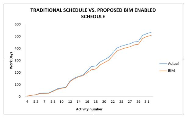
This finding is in line with what has already
been shown that an activity runs smoother when all of the required information is gathered before the commencement of works16. BIM is information rich at the design stage, on site all stakeholders can access the models from a project server, the information is updated if any changes are made and the models contain all dimensions, all elements, 3D views and schedules. Furthermore all of the elevations, sections and plans are coordinated and the design intent is clear. Access to this information is instantaneous and thus the use of BIM on a project can prevent schedule delays caused by RFI waiting times. The use of BIM as a communication tool is limited if the system is not properly implemented and if the BIM users are not aware of the full capabilities of the software.
The project was planned for a total of 163 days, the project actually ran for 171 days, thus it ran over schedule by 8 days Of the 29 project activities were carried out during the building works 11 of the project activities were completed within the allotted time, 7 of the activities were completed in a sh orter time than that predicted and 13 of the activities overran the project schedule. The average overrun per activity was 9.9 days. From analysing the construction documents the authors have found that the main causes of delay were problems encountered at the construction stage and schedule pressure. The ability of BIM to prevent schedule delays was analysed and a number of delays were deemed preventable, the ability of BIM to save, was determined by assessing 1. If through modelling,
visual checks and clash detection BIM was able to identify the cause of the delay at the planning stage, 2. Discussing the problems with the site manager and 3. by Analysing the construction documents (e.g. RFI’s and meeting minutes) It was found that using BIM could potentially prevent 4 of the 13 schedule overruns that occurred (Fig 4). The total possible time saving was found to be 12 days, as some of the activities were found to be on the schedule critical path. The overall time saving was 7.0% of the total project schedule and a saving of 4.5% on the total amount of working days.
This type of information flow found in the ‘over schedule’ activities is not optimum and is a welldocumented cause of delays38 It is clear that a lack of information during activities was a major cause of problems encountered during construction; time is lost waiting for information and design clarification from design consultants.
Clashes between different elements of the building also caused delays in the project schedule as time had to be taken to resolve and re-plan the issue, carry out the changes and in many cases there was rework involved As discussed, in the previous section using the BIM process produces better quality construction documents. Furthermore BIM is information rich, it includes information about all of the objects within the model, if BIM had been implemented on this project it would have minimised the need for RFI’s and enquiries.
Supply issues contributed to two of the delays that occurred on site. A delay was caused while waiting for delivery of the external windows and doors. Obviously BIM can’t solve delays associated with suppliers but it would enable prefabrication of elements offsite before construction, this would be an alternative to constructing the building, taking the measurements and then ordering the elements.
Schedule pressure is a knock-on effect of problems encountered onsite, in this project schedule pressure occurred after a 20 day dela y on the mechanical and electrical activities. The delays occurred on the activities that follow on from mechanical and electrical – internal plastering, floor screeds and ceiling finishes. In many cases, if BIM is implemented it can avoid schedule pressur e indirectly by eliminating construction problems.
Underestimation of the work involved in an activity was also a cause of extended activity time on this project. Using BIM, it is easier to understand the extent of the works and thus it is possible to create a more accurate project schedule.
An analysis was carried out in order to determine the potential cost savings that could be made if BIM were implemented on this case study. The costs were compiled from data received from the main contractor; the professional fees were calculated
according to the RIAI guidelines i.e. 11% of the construction cost.
We have calculated the main contractors planned profit (5.00% of the construction cost) and their actual profit (3.03% of the construction cos t). It was found that the main contractor’s profit margin was reduced. The cause of this is not known however from analysing the site records and from the BIM observations it is possible to speculate that the causes of the reduced profit margins were unanticipated work, delays, rework and purchase of extra materials. For a project of this size and duration the profits are relatively low, the profit per day during the implementation stage was €137, this figure is not taking into account the planning stage. On a project of this size profit margins are tight and thus in order for the main contractor to make a significant gain there is a need to reduce the risk involved. Furthermore in this economic climate the possibility of a main contractor having a number of projects running simultaneously is reduced and thus there is a need to increase profit margins.
An in depth analysis of the mechanical and electrical activities was conducted, as these activities are the most costly elements of the construction project, together costing 22.9% of the total construction cost. The author ’s assessed the savings that the subcontractor could make on the cost of labour if BIM were implemented and from this we have found the savings that could have been made by the main contractor. From analysing the sub-contractors costs and schedule the author ’s has found that if BIM were implemented and thus a number of onsite problems avoided, the mechanical and electrical subcontractors could have made labour cost savings of €5 ,500 and €8,400 respectively. Assuming that the labour cost savings were passed on to the main contractor as has occurred previously39, a saving of 1.4% of the total construction cost could have been made by the main contractor.
The benefits of BIM in terms of material cost estimation, cost budgeting, increasing tender accuracy and cost control at the design and tender stage have already been discussed and are achievable using the 5th dimension of BIM The benefits of the BIM process in terms of cost savings are also shown here. By avoiding construction problems and delays onsite it is possible to reduce the cost of labour. In addition to this the BIM process can reduce costs associated with redesigning due to error and costs associated with conducting unexpected or rework.
Based on the results of this case study it is the authors opinion that BIM can serve as a valuable tool for improving performance in several areas. In relation to this our main conclusions are 1. That BIM is a powerful communication tool. More efficient communication can benefit the client as the 3D models make it easier for the client to understand the design intent early in the de sign stage. 3D models of the building are also beneficial to the client for marketing and business purposes. The main and sub -contractors also benefit from the increased ease of communication. Having the clients design needs fully met at the planning stage reduces scope creep later in the construction phase and improved communication aids collaboration between the different disciplines. 2. The BIM process improves the quality of work. The overall quality of the construction documents, the quality of communication between different disciplines and the quality of the finished product. 3. BIM can serve as an accurate cost estimator however in a number of cases its estimations have not been precise. 4. BIM is very useful for creating a safety file for the operation and maintenance of the building at the end of the construction project. It provides a more accurate, less labour intensive and a more rapid means of compilation of data
Here we have also shown the benefits of the BIM process in terms of the levels of information that would be freely available to the construction team. In this study lack of information during the works correlated with activities that ran over the project schedule. In the BIM process the information is front loaded, this could help to prevent delays onsite. We have also shown here that if BIM were implemented, there could have been a significant saving in the number of days the construction team spent onsite. Finally, using BIM can be beneficial in terms of cost savings. From analysing the BIM savings on the cost of labour in the mechanical and electrical activities alone we have found that a saving of 1.4% of the total construction costs could have been made by the main contractor.
In light of this study the author ’s has made a number of recommendations for the use of BIM. Firstly, the BIM model for the Tuam case study was constructed using the annotations and 2D geometry outlined in traditional construction documents. As a result of this, any errors that are in the original documents carry a risk of being transferred to the BIM model thus BIM is more successful if it is applied from the design stage.
Secondly, for a BIM protocol to be completely successful all of the stakeholders and other parties involved i.e. the manufacturers must be BI M enabled, if not the use of BIM the will be affected.
This is most relevant in relation to 7D BIM i.e. the compilation of all of the operational and maintenance information relating to the facility. The authors have come to the conclusion that the construction sector in Ireland is not fully ready for 7D BIM as not all Irish stakeholders are BIM enabled and not all manufacturers provide 3D models and COBie informa tion of the building elements.
The UK government have implemented a 4 year strategy (commenced 2012) for the construction sector, by 2016 BIM must be fully operational as a 7D model on all public jobs greater than £5 million. To reap the benefits of more accurate and rapid compilation of operations and mai ntenance information the author’s suggests that a stagey similar to the one that has been put in place in the UK be implemented on public construction projects in Ireland.
[1] Howard, R., Björk B-C. (2007) Building information modelling – Experts’ views on standardisation and industry development. Advanced Engineering Informatics, vol. 22, pp. 271-280.
[2] Nederveen, V. and F. Tolman (1992). "Modeling multiple views on buildings." Journal of Automation in Construction 1(3): 215-224.
[3] Autodesk (2002) "Building Information Modellin g."
[4] Liaserin, J. (2002), Comparing Pommes and Naranjas, http://www.laiserin.com/features/issue15/feature01.php , accessed July 24, 2013
[5] Graphisoft (2013) www.graphisoft.com accessed July 24, 2013
[6] Bentley (2013) www.bentley.com accessed July 24, 2013
[7] National Institution of Building Sciences, (2007) The National Building Information Model Standard.
[8] The Royal Institute of the Architects of Ireland (RIAI) (2011) www.riai.ie
[9] Eastman (2011) BIM Handbook: A Guide to Building Information Modelling for Owners, Managers, Designers, Engineers and Contractors
[10] Ocsc (2010) www.ocsc.ie accessed July 24, 2013
[11] Holness & Gordon (2006) Building Information Modelling
[12] Underwood, J. & Isikdag, U., Emerging technologies for BIM 2.0, Construction Innovation: Information, Process, Management, 11 (3), pp. 252–258, 2011.
[13] Bew, M., Richards, M., Underwood, J. & Blackwell, B., Investors Report: Building Information Modelling (BIM), BSI, 2010.
[14] Autodesk (2008) 2D drawings just don’t give the same impact as 3D visualization
[15] Tekla. (2013). Retrieved 07 24, 2013, from Tekla: www.tekla.com accessed July 24, 2013
[16] Autodesk Building Solutions (2003) Building Information Modelling in Practice
[17] 'Building Information Modeling (BIM): Trends, Benefits, Risks, and Challenges for the AEC Industry', 2011. Leadership and Management in Engineering, 11 (3), pp. 241252.
[18] S. Azhar, J. Brown & R. Farooqui (2009) BIM -based Sustainability Analysis: An Evaluation of Building Performance Analysis Software.
[19] Schueter, A., and Thessling, F. (2008). “Building Information Model Based Energy/Exergy Performance Assessment in Early Design Stages”. Automation In Construction
[20] Boston Society of Architects (2005) Recycling construction and demolition wastes
[21] Morton, P. James; T. Emine (2011) of BIM and IPD within the UK AEC Industry: The Evolving Role of the Architectural Technologist.
[22] Hartmann, T., Gao, J. & Fischer, M., 2008. 'Areas of application for 3d and 4d models on construction projects'. Journal of construction engineering and management, 134 (10), pp. 776-785.
[23] Whyte, J., Bouchlaghem, N., Thorpe, A. & Mccaffer, R., 2000. 'From cad to virtual reality: modelling approaches, data exchange and interactive 3d building design tools'. Automation in construction, 10 (1), pp. 43-55.
[24] Yusuf, Arayici, Ghassan, Aouad (2005) Computer integrated construction: an approach to requirements engineering
[25] MA, Z., SHEN, Q. & ZHANG, J., 2005. 'Application of 4D for dynamic site layout and management of construction projects'. Automation in Construction, 14 (3), pp. 369 -381.
[26] SONG, Y. & CHUA, D.K.H., 2006. 'Modeling of Functional Construction Requirements for Constructability Analysis'. Journal of Construction Engineering and Management, 132 (12), pp. 1314-1326.
[27] CHAU, K.W., ANSON, M. & ZHANG, J.P., 2004. 'FourDimensional Visualization of Construction Scheduling and Site Utilization'. Journal of Construction Engineering and Management, 130 (4), pp. 598-606.
[28] CIFE Technical Reports. 2007. In: CIFE (ed.).
[29] STAUB-FRENCH, S., FISCHER, M., KUNZ, J. & PAULSON, B., 2003. 'An ontology for relating features with activities to calculate costs'. JOURNAL OF COMPUTING IN CIVIL ENGINEERING, 17 (4), pp. 243-254.
[30] 'BIM for sustainable design results of an industry survey', 2010. Journal of building information modelling.
[31] Louise Sabol (2008) Building Information Modeling & Facility Management
[32] CHRISTIAN, J. & PANDEYA, A., 1997. 'Cost Predictions of Facilities'. Journal of Management in Engineering, 13 (1), pp. 52-61.
[33] HARDIN, B., 2009a. BIM and Construction Management Proven Tools, Methods, and Workflows. Wiley.
[34] active projects, 2009. Available from: http://www.buildingsmartalliance.org/index.php/projects/acti veprojects/25.
[35] CHURCHER, D. & RICHARDS, M., 2011. Cross-discipline design deliverables for BIM Phase 1 report - Strategy Document, london.
[36] Luis F. Alarcón, Daniel A. Mardones (1998) improving the design-construction interface.
[37] GOODMAN, D., 2009. Fail to plan - plan to fail.7
[38] Caldas, Carlos H., Lucio Soibelman, and Jiawei Han. "Automated classification of construction project documents." Journal of Computing in Civil Engineering 16.4 (2002): 234-243.
[39] Khanzode, A., Fischer, M. & Reed, D. 2008. Benefits and lessons learned of implementing building virtual design and construction (VDC) technologies for coordination of mechanical, electrical, and plumbing (MEP) systems on a large healthcare project
[40] Tamera Lee, 2008. 'Scheduling, Estimating, and BIM: a Profitable Combination'. AACE International Transactions, p. BIM11.
3Department of Civil, Structural and Environmental Engineering, Trinity College, College Green, Dublin 2,
IrelandE-mail: 2barrymcauley@gmail.com 1alan.hore@dit.ie
rwest@tcd.ie
The Facilities Manager occupies a unique position within the lifecycle of a building asset, as he/she is one of the only Architectural, Engineering, and Construction/Facilities Management (AEC / FM) professionals who is in a position to view the product of the entire design and build process. Despite the potential benefits that the Facilities Manager offers, this profession still remains largely undeveloped and still does not command the recognition it deserves within the AEC/FM sector. This is beginning to change through the introduction of Building Information Modelling (BIM) which can offer a new level of functionality for the management of buildings and the physical assets within them, resulting in significant potential in regard to optimising facilities a nd life cycle management. However, in order for this process to be maximised it is imperative that the Facilities Manager plays a much more important role within the design and construction process, as he/she will be responsible for the operational phase w hich incurs approximately five times the initial capital cost. Despite this, at present the role of the Facilities Manager within this process is still uncertain with no set Key Performance I ndicators (KPI) or role designation being specified to date. This paper outlines how the Facilities Manager can play a pivotal role in the BIM process and will aim to establish the basis for a number of KPI’s that can be used for further study to help measure the benefit s of earlier FM involvement. The data collation methodology included the use of a BIM pilot project facilitated by the Construction IT Alliance in Ireland, which is primarily set around enhancing project focus from AEC to FM. It is hoped that the research findings will demonstrate the business case for the adoption of BIM and, in particular, the adoption of parti cular KPIs by Facility Managers leading to a more robust Lean FM practice.
Keywords Building Information Modelling, Facilities Management, Facility Manager, Key Performance Indicators, Pilot Project
In ever changing financial landscapes it is imperative that the construction sector reacts and participates in a new digital age and utilities the available tools at its disposal. One of the most interesting technologies to have emerged within the construction sector in recent years has come through the Building Information Modelling (BIM) process.
BIM is effectively a more productive method of managing the construction process with a long term view towards reducing life cycle costs of the associated assets within the project. The AEC / FM industry, as indicated by Azhar has long sought techniques to decrease project cost, increase productivity and quality, and reduce project delivery time in which BIM offers the potential to
achieve these objectives, as it stimulates the construction project in a virtual environment. [1]
As the AEC / FM Sector is undergoing a radical shift it‟s hardly surprising that facility managers would be among the first professionals to recognise the value of having their buildings designed, built, and operated using the BIM method as outlined by Ruiz The author further adds that this is in part due to the slumping economy; facility managers are concerned about how to operate and maintain their buildings more efficiently in order to save money [2] Facilities management (FM) as stated by Su et al represents one of the fastest growing sectors in real estate and construction. FM encompasses and requires multidisciplinary activities, and thus has extensive information requirements [3]. While some of these needs are addressed as highlighted by Gerber et al by several existing FM information systems, BIM, which is becoming widely adopted by the construction industry, holds undeveloped possibilities for providing and supporting FM practices with its functionalities of visualization, analysis, control, and so on [4]
In a recent survey of more than 60 building owners and FM professionals by Mortenson Construction shows that BIM/ Virtual Design and Construction (VDC), is key among owner professionals. When asked to identify the most exciting trend in FM and project delivery, 42% cited BIM/VDC as their top trend [5]. Some Advantages of BIM for FM as detailed by Sabol include:
Unified information base, providing a business owner‟s manual
Effective support for analysis, particularly for energy and sustainability initiatives
Support for emergency response and security management and scenario planning. [6]
Gerber et al further details some of the technology, process and organisational related challenges that include:
Unclear roles and responsibilities for loading data into the model or databases and maintaining the model.
Diversity in BIM and FM software tools, and interoperability issues.
Lack of effective collaboration between project stakeholders for modelling and model utilisation.
Necessity yet difficulty in software vendor‟s involvement, including fragmentation among different vendors, competition, and lack of common interests.
Cultural barriers toward adopting new technology.
Organisation wide resistance, need for investment in infrastructure, training, and new software tools.
Lack of real-world cases and positive proof of return of investment. [4]
BIM as detailed by Sabol is undergoing rapid adoption in the AEC / FM industry but is still a young technology and is just beginning to be adopted for use in FM [6]. We have barely scratched the surface of the “BIM for FM” topic , which is a vast and complex field by itself as claimed by Khemlani [7] The value of what BIM can bring to the FM sector as outlined by Mohammad and Hassanain is well detailed but there is still little literature available on the role the Facilities Manager can play in this process. Direct involvement of the Facility Manager in the design stage as has the potential to reduce maintainability problems during the operational phase of a facility [8] McAuley et al explains that t he Facilities Manager, if introduced at the beginning of a structure‟s life -cycle, has the potential to ensure that all the operational needs of the client are addressed at the onset of construction, as the Facilities Manager would adopt a longer term perspective on the facilities created, in the construction and design of the structure. [9].There has been as outlined by Wang et al. little research performed that has identified a framework to the approach and benefit of integrating FM in the early design stage. This can avoid and reduce the potential issues, such as rework and inappropriate allocation of workspace in the operational phase [10].
The authors in expanding on this research have set through a pilot project, about measuring the value which early FM involvement can add to the BIM process. The authors have created a unique set of Key Performance Indicators (KPI) to measure the complete Pilot process, in which it is hoped that a further set of KPI‟s can be established to help build on the role in which the Facilities Manager can play in the BIM process if incorporated into a design role from the beginning.
At present the uptake of BIM within Ireland is slow and there has been little encouragement from the Irish Government. The reality as highlighted by McAuley et al is that this is highly unlikely, as the Government Construction Contracts Committee forms of contracts would have to provide BIM procedures or an execution plan template, as part
of the Capital Works Management Framework guidelines, which at present seems unlikely due to low tender prices been already achieved [11].While a real project as outlined by the pilot chair Paul Sexton is not available at this time, a virtual project was identified which would offer the opportunity to experience and disseminate practical lessons on proof of concept and the potential benefits/risks involved. Through the integration of the team and using smarter workflows and technologies to facilitate more collaborative practice, could result in better value for all involved, particularly the client and facility operation. The key objectives of the Technology Pilot are:
1. Focus on integrating the team and fostering collaborative working/ decision making throughout all stages of the process.
2. Use a variety of „BIM' authoring and interface tools/ technologies plus other ICT to enable/ streamline the efficiency of the process.
3. Deliberately shift project focus from design and construction to FM and operation/ whole life cycle.
4. Focus on the removal of waste (time, material, resources and effort) and only those things that add value for the Client & project Team.
5. Focus on the Real Value created with attempt to qualify/ quantity during the process for project team including client and FM. [12]
The key objectives are strongly based around ensuring that the FM process is brought to the beginning of the design process. To achieve this along with the other goals a transparent environment was established in which all pilot companies had open communication and access to each other‟s work. This also resulted in an attempt to incorporate all professions into an Integrated Project Delivery (IPD) environment which included the FM Team. As the FM Team wouldn't normally be involved in a traditional process it permitted the opportunity for their early input, as to what they want in the building, and how they want the information to be delivered at the end, so as to facilitate their job in reducing the impact of the overall lifecycle cost. The purpose of the pilot was not just to focus on the FM Team but on the overall contribution to what each member within the Pilot Team can offer in reducing life cycle costs. This is important as the FM Team within the Pilot are primarily focused on best practice for the collection and handover of documentation. The focus of the entire pilot team shifting project focus from design and construction to FM will permit a greater understanding of how a new more digitally focused FM practice can be realised through early FM involvement. This will offer the opportunity for the authors to put in place the development of a Lean FM process through mapping the interactions of the FM Team and other professionals within the BIM Process.
The authors were tasked with creating a set of KPI‟s that could be used to measure the benefit of the pilot process.
The concept of using indicators as outlined by Haponava and Jibouri, to assess performance originates from the theory of benchmarking used in many industries for improving business processes and products. The concept involves measuring one or more aspects of the business or part of it and comparing it with the best in its specific sector [13]. Barbuio explains that KPIs are used because they highlight those aspects of performance that are integral above all others in providing insights on performance and how it can be improved[14] Coates et al claim that the following attributes are sought for the definition of KPIs:
Does the KPI motivate the right behaviour?
Is the KPI measurable?
Is the measurement of this KPI affordable (cost-effective)?
Is the target value attainable?
Are the factors affecting this KPI controlled by you?
Is the KPI meaningful?
The author‟s further state KPIs can form a method of comparing the success of different BIM adoptions in terms of:
Measuring the quality of projects
Standardising information and measurement process throughout the community.
Setting appropriate benchmarking targets
Recording effectiveness of action [15]
Sun and Zhou further detail more KPI‟s that are helpful in comparing the actual and estimated performance in terms of effectiveness, efficiency and quality of both workmanship and pr oduct. The five primary BIM KPIs that were selected by the authors included quality, cost, time, safety and energy [16] BIM adopters as outlined by Mom and Hseih may choose a single or mixed framework based on their own needs. The performance measures should be as small as possible and new measures are added to account for changes [17].
The KPI‟s were designed around the five over reaching aims of the CITA Technology Pilot. The overall attributes detailed below were used to help define the major KPIs:
Acceptable – they can be understood; Suitable – they measure important things;
Feasible – they are easy to collect; Effective
they concentrate on encouraging the right behaviour; and Aligned –non financial measures must link to financial goals.
Taking into account all of the pilot aims and attributes in establishing KPIs and recent KPI suggestions, the following KPIs have been drafted for the CITA Technology Pilot:
1. Pilot Team Skills and Knowledge Development (KPI 1)
- This will measure the pilot team‟s reaction and acceptance, their cultural attitudes, their skill and knowledge level and related software training will also be measured and managed accordingly. This should seek to measure where the value for each member of the team lies.
2. Trust (KPI 2)
- This will aim to measure the high levels of trust and respect within the pilot team, effective communications, pilot team satisfaction and cultural alignment between client and pilot team. This should ultimately aim to quantify the benefits of team integration and close collaboration
3. 4D and 5D Technologies: Time, Safety and Budget (KPI 3, 4, 5). On further research these are the three main KPIs that are valued the highest when it comes to 4D and 5D Technologies:
- Time: This should measure the benefits of using a 4D scheduling and planning approach and the possible reduction in the pilot programme that comes with this process. This should also aim to measure the team‟s time and expenses associated with the pilot, as well as, preparation for Building Regulations Submission.
- Safety: This will measure Health, safety and environmental considerations for both the client and stakeholders.
- Budget: This will aim to measure the savings in regards to how the adoption of current technologies can result in savings for the project.
4. Early FM Involvement: Environmental, Financial Management, Functionality and Effectiveness, and, FM and Construction Team Engagement (KPI 6, 7, 8, 9) . The following KPIs (6,7 and 8) are being used by the UK FM Cabinet Office to establish the key measures / areas from the early stage of design into post occupancy, as they pass through the whole BIM process. These KPI‟s will aim to measure the:
- Environmental: The measurement of energy usage pre and post occupancy. This should measure energy including embodied carbon.
- Financial Management: The operational expenditure.
- Functionality and Effectiveness: What was achieved at the end of it the whole process and was it fit for purpose. This should measure construction and quality assurance.
- FM and Construction Team Engagement: To measure the value and barriers associated with the involvement of the Facilities Manager with the design and construction team from the start of the BIM process.
5. Client Satisfaction (KPI 10)
- This will measure if the client‟s awareness has become more sophisticated and their financial budgeting moves towards a more holistic process to incorporate wider environmental considerations. This will also aim to measure the effective management of the client‟s requirements and where the value lies for the client.
6. Waste (KPI 11)
- To measure the part that technology can play in the reduction of waste and, therefore, CO2 emissions through the fostering of better offsite fabrication techniques and better practices both financially and environmental.
The pilot project timeframe was commissioned from January to November to run in tandem with the CITA Technology Series. The following progress to date represents work carried out from January until early June. The authors‟ role within the Pilot was to act as the chief researchers and to ensure a measurement tool was in place to map the progress of the Pilot Team. Though the KPIs where not the focus of the pilot team, it was one of the main research goals of the authors. The pilot project as outlined in the next section will give a generic look of the pilot to date in which will be translated into KPIs. It is hoped through the broad scope of KPI‟s used to measure progress to date, will lead to the development of a future set of KPI‟s primarily related to the FM profession. This will be achieved through a greater understanding of how each profession interacts with the FM Team and uses their knowledge to bring the FM process to the beginning of the design process. This will allow the authors an understanding, as so to further suggest key areas where early FM interaction snd decesions could prove key to the BIM process. The original framework for the Pilot Project resulted in a development map that produced a number of interesting areas in which the topographical areas where complicated ,
resulting in it being too difficult to design on a 2D campus. This resulted in an enhanced brief be ing suggested to the Client for the creation of a virtual model for the whole area which could be further used to analyse and investigate best design options This virtual interactive model could also be utilised by the planning department to analyse planning applications. This model further presented an interesting building in the form of Rowlestown community centre. The community centre was in need of some form of refurbishment and offered the chance for the CITA Pilot Team to create a sustainable and functional building.
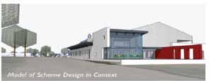
Survey data was provided for the project through three combined methods that consisted of firstly setting up a Global Positioning System (GPS) grid of the area, and then secondly, as there were no drawings of the area or detailed surveys, a Unmanned aerial vehicle (UAV) was flown over the area capturing digital information. The UAV was pre-programmed using Google earth and GP S, and was flown over the area to create a digital model of the area over a four hour period. Thirdly this data was combined with the laser scan of the building. Using a cloud based solution provided by Team Platform a full colour point cloud could be given to every team member.
platform to make decisions in which plans, sections and elevations could be easily generated.
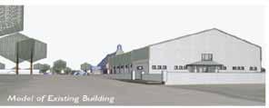
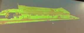
Before commencement of the scheme design there were a number of different standards investigated. The AEC (UK) BIM Standards where consulted before modelling began and it was decided through these standards that file naming convention would be adapted. All the library objects would al so be renamed with a uniclass 2. The 3D terrain model received from survey data was then imported into Archicad, which was further taken through Google Sketchup. Cloud data was also received. The point data was explored by importing into Google Sketchup. The team received a complete model of the building which was 30GB in size The survey information originally imported into the platform of Archicad took up to 8 hours to import. A simplified model (300 Mb) was used with 20 million point cloud and a setting filter distance which took only an hour and half to import, thu s creating a simplified 3D model picture. Through combined point cloud data and orthorectified imagery a building model was constructed. As textures where applied to the model, it became more realistic and gave a good
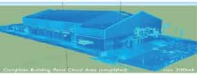
The model was shared through Tekla BIM sight and Solibri through IFC By running the model through both Tekla BIM sight and Solibri it represented the opportunity to verify the integrity of the model through two different platforms. Some issues were raised between Tekla and Solari included a 5-10% difference in quantities. A further meeting also took place with the Client and a brief was created. This brief involved two phases of the project with phase one ultimately aiming to revaluate the current structure and produce a solution for a more functional building. This has been based around the Clients needs, which includes better thermal comfort, enhanced artificial lighting, improved acoustics, up grade to the Crèche, as well as the addition of a shop unit. Through the use of Skype and dropbox amo ngst other methods the building began to be designed while interacting online. Layers were created in Photoshop and once an outline design was created it could be modelled and checked in Ecotect wind model. It was found the new suggested extensions to the building would deflect the wind.
The FM Pilot Team began to become involved and informed that COBie would be used as the main data exchange for the deliverables for FM data. Data for FM only comes in at the end of a project but in a true environment this data sho uld be received from them at the start. The first opportunity to see information coming from the model was through an IFC file created by the pilot
Architect. This was exported into a software tool that would develop a documentation index called InControl DFM Software. The FM team noted that there is no direct means of getting a datasheet from a BIM model. The documentation for the item within the model is embedded and may have ten pieces of information leading to a very large Spreadsheet. The model was revised to incorporate all the information put in by the FM team Synchro was used for site logistics and mapped with a project schedule. The survey data showed a large drop resulting in the only place to position the on-site compound being beside this. This allows the contractor from the offset to see where a number of possible problem areas may occur. It also allows for a number of construction methodologies to be examined and further savings for the client. The building‟s interior was model led so that an informed design could be undertaken. This resulted in the client and planning authorities being able to easily understand the design intent within the location.
The pilot team along with the M&E designer sat around the table and discussed the vision with regards to plant. The space was divided into four different areas of retail, office and general use areas, meeting rooms, general purpose hall and crèche. The first task was to reduce the energy cost and so, therefore, it was important to go around each of the elements and assess the possible U-value that can be achieved, air tightness and sealing around elements. The M&E pilot consultants conducted heat analysis and cooling loads on these elements. In terms of ventilation and heating there was not a passive solution that lent itself to the structure in regards to the hall. It was agreed to reuse the original floor ducts and put a package unit at ground floor for maintenance purpose for easy access. This would improve the ventilation through the space by providing heating and cooling, so it could modulate to match the occupancy levels. A plant space was created in a hidden area behind the roof by the architect. Fan coil units were placed in the meeting room‟s areas, as these areas would fluctuate quite differently from one day to the next depending on occupancy levels. The crèche was treated as an independent area, as so it could be meter ed separately with the idea to put a small heat pump for underground heating to avoid high surface temperature for the children. This ensures that there would be heat ventilation circulation to make sure the place could be heated without having to open all the windows.
The areas of FM and whole life cycle costing were strongly taken on board There was a deck area and below it directly is the plant room. The AH Package unit was placed there and the heat pump located within a room beside it. This was also designed with the view of ease of access to ensure that all future maintenance could easily take place. A
BMS was also considered which would depended on price which would enable the building to become more user friendly and prevent a lack of information causing further problems. This would allow the option to control running costs and a web alert or sms alert to be sent to designated people to inform them if the building needs attention.
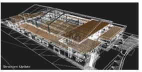
The model has incorporated all the structural and M&E information. Some outline specification has been drafted for the purpose of the QS, with all elements being classified in accordance with uniclass 2. The objective of the pilot QS Team was to produce a cost plan from both 2D and 3D. The preliminary cost plan has been calculated in both 2D and 3D information
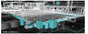
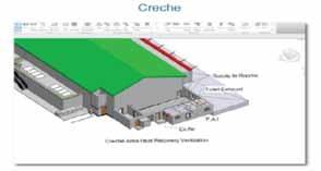
The previous section provided a detailed summary to date. In order for this progr ess to be translated into KPIs an extensive online survey was conducted. This was complimented with on-going interaction with all pilot team members to help further validate the KPI‟s accuracy. Each of the pilot team company members where emailed an online link to complete the survey. Each question
had five options of no change, little change, some change, significant change and much change. The results will focus more strongly on the FM Teams experience to date. The following results where noted:
KPI 1 - 70% of the team reported some to significant change across the board when it came to knowledge, communication and collaboration skills, software skills and attitude. Everyone within the pilot team received some change in their knowledge. The FM Team where the only pilot team members who have had no change in communication, collaboration and software skills to date. Despite this it was noted that it has been a positive experience and it is encouraging to see how other consultants work, what their requirements are etc.
KPI 2 – There was a high change of trust across the board with 80% of the pilot team members reporting some to significant change. The FM Team reported no change in trust in regards to other disciplines or effective communication within the plot team. There was a belief by some of the pilot team that there has been transparency through open discussions in regards to true experiences which has allowed an understanding of the pilot team member's requirements better.
KPI 3 – It must be noted that the contractor was changed during the pilot, and the new contractor did not have really have an opportunity to use 4D constructability review and planning and health & safety review through BIM. There was divided opinions in regards to reduction in the pilot programme by using 4D technologies compared to other traditional construction projects, with the FM and QS team reporting no change and the Geographical Survey team stating a significant change. 50% of the pilot team reported some change in their time and expense which they have encountered by working within the pilot.
KPI 4 – The views were split in regards to 4D technologies providing an advantage in regards to health and safety, with the FM team reporting no change and the geographical survey team and Architect reporting a significant change. 75% of the pilot team reported some to a significant change in environmental considerations through the use of 4D technologies.
KPI 5 –83% of the pilot team believed that 5D technologies have been an advantage in predicting budgets; reducing time spent on budgets and cost reductions in the budget. The Architect noted that for investigation of design options it would be significant if 5D costing
occurred in the earlier stages for optimal feedback
KPI 6 - 75% of the pilot team claimed that there was some to a significant change from having early FM input in regards to the measurement of energy usage pre and post occupancy. Early involvement and early adoption of end user FM systems was seen as vital component within the BIM process. Early FM management can dictate the best positioning and materials and processes to be used in any project. There has been very little done in this regard to date as noted by the FM Team and has predominantly been carried out by the M&E consultant
KPI 7 - 75% of the pilot team believed that the Facilities Manager can help improve operational expenditure. The Architect and steel manufacturing team indicated a significant change while the contractor indicated no change. The Architect has noted that the earlier systems are specified and integrated into the design the better chance they have to impact the financial management. Other pilot team members have noted that the preference for sustainability and low running costs post contract has led to the M&E estimates being quite high as stated by the Q S. The FM Team have noted that early indications suggest that it will cost more at design stage for FM Involvement.
KPI 8 - 87.5% of the pilot team noted advantages across the board in regards to early FM involvement in increasing the Functionality & Effectiveness. There was a significant change noted of 50% when it comes to maximising the sustainability potential. The pilot contractor stated that there has been no change from early FM involvement. The QS noted that early involvement will inform the design team of the Facilities Manager needs post contract and can therefore design accordingly from the outset instead of changing during tender stage or post contract stage. The geographical surveying pilot team member stated that early FM involvement is a must for the functionality of the project, bringing in new skills at an early stage can only be beneficial, for energy use/ building layout. T he Architect acknowledged that advance knowledge and FM systems choice means advanced ways to simulate and optimise the systems to be installed.
KPI 9 - The whole pilot team believed that the Facilities Manager can bring some to significant added value / change to the design team. The FM team believed the Facilities Manager can bring added value / change to the design
team but there has been little involvement to date. The Architect noted that it was important to have the Facilities Manager involved early on, as the consultant has requirements on how objects are encoded to contain as much COBie data as possible.
KPI 10 –50% of the respondents claimed that there has been a significant change in the clients awareness and 81% reported some to significant change in the clients budgeting moving towards a more holistic approach and effective management of the clients requirement.
KPI 11 – All of the pilot team claimed that technology can help reduce construction and C02 waste in some to a significant way. The geographical surveying team noted that technology reduced the time they spent on site by 45%.
The CITA Pilot‟s aim was ultimately to shift project focus from design and construction to FM and o peration/ whole life cycle. To achieve this the Facilities Manager was integrated, as part of the design team, within the BIM process. The authors established a set of unique KPI‟s to help measure the benefits of the BIM process and the role early ado ption of the Facilities Manager can play. The pilot project to date is mid-way and all of the pilot team are in the agreement that the Facilities Manager can play a significant role in ensuring the most functional and practical structure can be realised. The Facilities Manager can help ensure that the most relevant data is embedded into the model that will be of most benefit when it comes to the operation of the building. However, there are signs within the pilot that the Facilities Manager is unsure of the benefit that they can provide and have not like other profe ssions advanced their communication, trust, collaboration and software skills. The most benefit that has been achieved in the FM field within the pilot has resulted from the M&E team who have designed the building to be more sustainable and energy efficient. There is also the concern that it will cost more at design stage for FM Involvement. The FM team believe that the Facilities Manager can bring added value to the design team but as of yet there has been little involvement. This may change as the pilot a dvances and the role of the Facilities Manger will continue to be measured and monitored. The pilot project has helped establish the beginning of a new Lean FM practice to be developed by the author. Though the Facilities Manger to date has not partic ipated in the role that the feel they could offer the most potential as a professional, it has permitted the author the opportunity to view and record first hand through the transparent nature of the pilot the barr iers that currently exist. This result will help further develop a unique set of KPI‟s that can be used to
help measure and guide Facility Manger interaction within the BIM process from an early stage. It is also hoped that these KPIs can be used to measure and guide a new process been researched by the authors in which the Facilities Manager will operate as a key professional. It is hoped that this will advocate the adoption of a more robust Lean FM.
[1] Azhar S, Building Information Modeling (BIM): Trends, Benefits, Risks, and Challenges for the AEC Industry, Leadership and Management in Engineering, pp. 241 – 252, July 2011
[2] Ruiz M, FM Issue: Transforming Technologies, Todays Facilities Manager, 2010, available from http://www.todaysfacilitymanager.com/2010/09/fm -issue-transforming-technologies > accessed (09/07/2012)
[3] Yu Chih Su, Yi Chien Lee, Yu Cheng Lin, E nhancing Maintenance Management Using Building Information Modeling In Facilities Management, Proceedings of the 28th ISARC, Seoul, Korea 2011
[4] Gerber B.B, Jazizadeh F, Li N and Calis G, BIM-Enabled Facilities Management, Journal of Construction Engineering and Managemen t, June, 2011 fmjonline.com.
[5] Mortenson Construction, Building owners cite BIM/VDC as 'most exciting trend' in facilities management, says Mortenson report , BDC Network, available from http://www.bdcnetwork.com/building-owners-citebimvdc-most-exciting-trend-facilitiesmanagement-says-mortenson-report > accessed (02/07/2013)
[6] Sabbol L, BIM Technology For FM, BIM for Facility Managers, John Wiley and Sons Inc, pp 17-46, 2013
[7] Khemlani L (2011) BIM for Facilities Management, AECbytes Feature, available at < http://www.aecbytes.com/feature/2011/BIMforFM. html> accessed (09/07/2011)
[8] Mohammed A M and Hassanain M A, Towards Improvement in Facilities Operation and Maintenance through Feedback to the Design Team, The Built & Human Environment Review, Volume 3, 2010
[9] McAuley B, Hore A V, West R & Wall J, The Economic Case for Early Adoption of Facilities Management, Proceedings of the Joint CIB W070, W092 & Tg72 International Conference on Deli vering Value to the Community, University of Cape Town, 23-25 January 2012
[10]Wang Y, Wang X, Wang J, Yung P and Jun G Engagement of FM in Design Stage through BIM: Framework and a Case Study, Advances in Civil Engineering, Volume 2013
[11]McAuley B, Hore A.V and West Implementing of Building Information Modelling in Public Works Projects in Ireland, Proceedings of the 9th European Conference on Product and Process Modelling, Reykjavik, July 25 – 27th, 2012
[12]CITA, CITA Technology Pilot 2013, available from < http://www.cita.ie/cita_pilot_project_2013.asp > accessed (19/6/2013)
[13] Haponava T and Jibouri S A, Identifying key performance indicators for use in control of preproject stage process in construction, International Journal of Productivity and Performance Manag ement, Vol. 58 No. 2, 2009 pp. 160 -173
[14] Barbuio F Performance Measurement: A Pract ical Guide to KPIs and Benchmarking in Public Broadcasters, Commonwealth Broadcasting Association, 2007
[15] Coates O, Arayici Y, Koskela L, Kagioglou M, Usher C and O‟Reilly K, The key performance ind icators of the BIM implementation process, Proceedings of the International Conference on Computing in Civil and Building Engin eering, Nottingham, UK 2010
[16] Suni W Z and Zhou G Q, KPIs: Analysing the impact of Building Information Modeling on co nstruction industry in China, 17th International Conference on. Industrial Engineering and Engineering Management, 2010
[17] Mom M and Hsieh H, Toward performance assessment of BIM technology implementation, Proceedings of the International Conference on Computing in Civil and Building Engineering , Moscow, Russia 2012
- SCEG Ltd
- Cummins and Voortman Ltd.
- Construct IT.
- John Paul Construction Ltd.
- CITA Ltd.
- Nugent Manufacturing Ltd
- Moore DFM
- iCON Arch & Urban Design
- Coastway Ltd.
- Cahill-O'Brien Associates Ltd
- Johnston Reid & Associates.
- Programme Project Managment Ltd.
- Austin Reddy
- Stewart Construction.
- Fingal County Council.
Abstract
In the retail sector the demise of Jessops, HMV, Blockbuster and the success of companies like Amazon shows how the influence of digital consumerism is changing our shopping patterns. Businesses have had to change in response to the digital onslaught to survive. This is truly a Darwinian moment. Against the backdrop of much broader global and national perspectives, these developments are just a small part of the fast changing world in which we now live.
Change, evolution, is a given and a constant now. What does this mean for the built environment industry? This paper/presentation will consider some background issues before looking at how BIM can help us respond, adapt and move forward in transforming our industry and society. Perhaps normal just doesn’t exist anymore. The paradigms that we Baby Boomers grew up with no longer hold true and are shifting beneath our feet. Technology is just one strand of many factors that are affecting our daily lives. For example: climate change, energy, carbon, natural resources, technologies, population, demographics, new skills and scientific frontiers, and the new economics – the slow fall of the west, and the rise of the east.
These filter down into the construction industry and influence the kind of projects that we can deliver and how we work. And yet in the centre of this perfect storm, our industry becomes a lens on society, embodying “the spirit of the age” as described by Nikolas Pevsner in the buildings we produce and the environment we create. BIM is a catalyst for change as well as a lens on society. This paper will discuss both the high level factors, BIM as a lens/catalyst and some ideas on future impacts on society, our industry, professions and institutions.
Keywords BIM, Change, Technology, Big Data, Evolution, Digital
BIM or Building Information Modelling has become a hot topic over the last few years.
1 - Let’s remember that BIM is about much more than just buildings, it could be any constructed asset, for example a road, bridge, oil rig, tunnel, rail line, airport, nuclear power station etc.
2 – BIM is about data management, collaboration, and communication
3 – BIM is about information management over the whole lifecycle of any asset, connecting, integrating, and structuring all the data that we produce at every stage. Perfect data – the single source of truth for the asset.
At the moment using BIM as a tagline is a sure fire success if used for a conference, leading to packed audiences, and yet as a subject is still widely misunderstood by most of the built environment industry, particularly SME’s and supply chain in
any of the sectors or disciplines. Businesses, organisations and individuals that really “get” BIM are still mainly in the minority, although the balance is rapidly changing.
In the retail sector the demise of the likes of Jessops, HMV, Blockbuster and the success of companies like Amazon show how the influence of digital consumerism is changing our shopping patterns and as a result businesses have had to change in response to the digital onslaught if they are to survive. The evolution in the construction industry will and is following a similar pattern.
This is truly a Darwinian moment for the construction industry, and not all will successfully make the transition. The survivors and successors will be radically different to their pre-BIM ancestors. “It is not the strongest of species that survive nor the most intelligent but the ones most responsive to change.” – Charles Darwin.
The music industry is again another recent example of digital impact. The advent of iTunes in the last decade revolutionised how music is made and distributed, and changed the industry financial models for artists, producers and consumers.
Against the backdrop of much broader global and national perspectives, these developments are just a small part of the changing world in which we now live. Paradigms that we thought would remain stable for all of our lives are now shifting beneath our feet, just as the geological tectonic plates have shifted over millennia rearranging the earth’s geography. Change, evolution, is a given and a constant now, and the sooner we adjust and acclimatise the better it will be for us and for our future generations.
What does this mean for the built environment industry? Included in this discussion are any form of infrastructure and built asset. Let’s consider some background issues before looking at how BIM can help us respond, adapt and move forward in transforming our industry. Remember BIM is not new technology, other industries such as aerospace, petrochem and automotive adopted this way of working decades ago. Also we will consider some issues that transcend the construction industry and have implications for the Smart Society.
But first, lets go down to the beach… Jaron Lanier in his book, Who owns the future? explores the
impact of the digital age on society, and begins to consider the economic and social consequences.
It may have some surprising implications as illustrated by his allegory:
“It’s sometime later in the 21 st century, and you’re at the beach. A neuro-interfaced seagull perches and seems to speak, telling you that nanobots are repairing your heart valve at the moment (who knew you had a looming heart problem?) and the sponsor is the casino up the road, which paid for this avian message and the automatic cardiology through Google or whatever company is running that sort of switchboard service decades hence.” [1]
Imagine a totally pervasive digital environment, connected, mobile, all embracing. As Lanier goes on to discuss: “This is the thought schema of a thousand inspirational talks, and the motivation behind a great many start-ups, courses, and careers. The key terms associated with this sensibility are accelerating change, abundance, and singularity.” [2]
“Assume that:
• Hard drive space is free
• Wifi-like connections are everywhere
• Connection speeds are 10 to 100 time faster
• Everyone has a digital camera
• Everyone carries a device that is sort of like a laptop, but cheap and tiny
• The number of new products introduced everyday is five times greater than now
• Walmart’s sales are three times as big as they are now
• Any manufactured product that’s more than five years old in design sells at commodity pricing
• The retirement age will be five years higher than it is now
• Your current profession/job will either be gone or totally different.
•
- What then?” [3]
This was written by Seth Godin in 2004, with tremendous foresight and vision, predicting the impact of digital technologies not only on the hardware we use, faster, smaller, lighter, cheaper, but also how it would increasingly affect our daily lives.
Business in the 2020s, industry in the 2050s, the paradigm shifts
-Paradigm shift- a fundamental change in approach or underlying assumptions - Oxford Dictionary of English.
For us Baby Boomers and Gen X we’ve seen it all happen within our own lifetimes, experiencing the explosion of technology and connectivity that has changed and is continuing to change our world. For the Gen Y’s, the Millennials, (born post 1982) this is the new normal. Brought up on a diet of technology and new gadget launches every few weeks. It’s now a case of – “When can I have the next new thing – I want it now!” This has bred an instant generation, who want immediate results –waiting is just downtime and boring...
Perhaps the “normal” that we Baby Boomers have grown to expect and rely upon, just doesn’t exist anymore. The paradigms that we grew up with no longer hold true and the geological plates that have been stable for many years making up our lives are now shifting on an unparalleled scale beneath our feet.
For example:
• One job for life
• Married and two children by 30
• Get on the property ladder
• Married (if at all)
• Only one job at a time
• Stay in a job/place for several years
• Leave your parents as soon as possible, stand on your own feet
• Education is free
• The state will care for you.
Consider also the technology… if you need to know anything at all about anybody or anything, just Google it. Information on anything, available 24/7, all the things, subjects, people you can think of. You can see hear/see anything, talk to anyone. There is more information immediately available at our fingertips than anyone could hope to absorb even in several lifetimes. Our lives have gone digital, and it is now taken for granted. Our village is now the globe, social networks abound. Everyday we all are trading data and information; it is the currency of our lives. Change is increasing on an exponential scale. And it isn’t just about technology. This is just one strand of many factors
that are affecting our daily lives.
There is a project by Arup and their Foresight Team called “Drivers of Change” www.driversofchange.com
They have produced a toolkit that looks at these factors under the following headings: Convergence, Oceans, Food, Poverty, Energy, Urbanisation, Demographics, Water, Waste, and Climate change
The challenge for us is that so many strands and factors are interconnected now and cross boundaries between influences, subjects and sectors. As we have seen recently climate change is becoming a reality. Tell that to the people who’ve just been flooded for the third time last year.
Shortages of natural resources, water, energy, oil, gas. Difficulties in extraction, leading to rising costs. Increasing population growth, fragmentation of society, reduced opportunities for the young, people living longer, becoming a burden to the state and a shrinking workforce. Economic stringency.
Pressure is building on all sides and from a variety of directions. These all filter down into the construction industry and influence the kind of outcomes and projects that we can deliver and how we work. Project practices become more sustainable, optimised for lifecycle performance, achieving faster build times using off site techniques, and real time post occupancy evaluation and operational management.
BIM can offer a platform to assist delivery of all of this and more, providing benefits to all stakeholders at all stages of the process.
At a time of great economic stringency the UK Government push on BIM has kept it on the agenda, when perhaps ordinarily most businesses would have put it in the too difficult box or long grass. BIM Level 2 in 2016 is still a confusing and misunderstood target for some, but the Ministry of Justice are clear on the benefits and have brought their deadline forward to end of this year to have at least Level 2 BIM on all their projects. (A substantial 6 figure saving on one of their pilot BIM projects probably helped here!)
The strategy is driven by two main objectives: to reduce capital project costs and reduce carbon emissions. The “One Year On” report outlines savings already made in the first 12 months, partly attributable to BIM and other initiatives. BIM provides access to efficiencies and economies, saving time, effort and waste through the use of consistent, structured data.
The UK strategy and implementation continues to grow, develop and gather momentum. The website, www.bimtaskgroup.org, contains information and downloads on all aspects including latest news, pilot projects, working parties, standards and more.
In the first quarter of this year key documents were released which put in place some key frameworks for BIM in the UK.
These include:
PAS1192 Part 2:2013 Building Information Management – Information requirements for the capital delivery phase of construction projects. This develops the work of BS1192 (2007) and sets guidelines for using BIM, in a Common Data Environment on projects. This includes definition of the role of Information Manager – the key role in co-ordinating BIM (Common Data) Environments.
PAS 91;2013 Construction related procurement Prequalification questionnaires. This sets the format for public sector prequalification documents and is mandated by the Government Construction Strategy. Included in this update are PQQ questions on BIM, which will be used by public sector clients in the supply chain selection process. The BIM questions cover subjects such as protocols, processes, documentation and training.
BIM Protocols. This document sets out contractual requirements for BIM on a project and can be used as a contract supplement.
The Digital Plan of Work, bringing together work from the last 12 months, integrating various industry-wide plans of work into a unified framework. Alongside this will be Level of Detail/Development plans illustrating model development and data requirements at each stage. The updated RIBA Plan of Work 2013 aligns with this framework.
Already on the BIM Task Group website can be found the COBie UK 2012 document, which sets out COBie requirements and templates. (COBie stands for Construction Operations Building
information exchange. It is essentially a spread sheet, and is a way of exchanging data outputs from BIM models. The data outputs are defined at various stages and are being aligned across Government departments for consistency.)
Over the coming 12 months BIM will continue to grow and develop across the UK. Some trends to look out for are as follows:
Demand – Use of BIM will reach critical mass in the market for demand by clients and other stakeholders. The Government strategy will motor on this year, percolating down into more UK Government departments, local authorities and public sector organisations and clients. Increasingly requirements for BIM included in PQQs and tender documents.
“The Gap” – will widen. Leading BIM exponents, early adopters, including designers, leading contractors and suppliers, will turn BIM into real competitive advantage. Winning more work, providing services and project certainty that nonBIM companies will not be able to match. These are the early adopters who began their BIM journey at least a few years ago. Now it is embedded in their process and culture, “ it’s just the way we work.”
Natural selection - Sadly there will be more business failures. The recession is taking its toll, but the evolutionary changes and demands that our industry is facing will start to bite with a vengeance this year. Embrace change (BIM) to survive. Darwin could have written his "On the Origin of Species" for such a time as this.
New competition - "Left field" players will enter our industry, free of the traditional construction industry baggage, players from other industries will use BIM to enter the construction industry and really compete. This is a big threat to the leading traditional players. Offsite manufacture, Design for Manufacture, Computer Aided FM are prime targets...its only a matter of time. Long established construction firms will have to look over their shoulders at the new kids on the block, who very quickly could outperform their more traditional rivals.
SME's - Whilst the early adopters and big players get their BIM ducks in a row, the delivery will only be as good as the supply chain capability, and their engagement with BIM environments. So
there will be a focus on getting supply chains geared up to work in BIM environments.
Changing working culture - BIM requires more collaboration, integrated teams, new workflows and ways of working requiring business and cultural change on a grand scale. It takes time to imbue these qualities into an organization. BIM is not a quick fix.
BIM business as usual - Level 2 is only the first stop on the journey, and some of the early adopters are going to be pushing the boundaries and beyond.
reference and membership as their members develop increasingly diverse skills, way beyond what we think of as the traditional roles now. An eminent speaker at a recent conference thought that we would have an all-embracing “super institute” within five years.
BIM as the Trojan horse of disruptive innovation poses questions and challenges to everything it touches. Within a generation the landscape of our industry, education and institutional networks could be very different.
3D printing
Already causing a stir, but the concept of BIM driven manufacture is becoming accessible to the masses through reducing costs of the kit required. Recent examples already include a house, personalized models, spare parts for the US Navy, and even sex toys!
IOT – Internet of Things – Everything has an IP address, and devices, assets start “talking” to each other without human intervention. Sharing data, through smart networks and grids. This is the “smart” future.
As BIM technology and the related tools and processes become embedded and second nature to businesses and organisations, we will see a blurring and also growth across what are currently traditional tribe or silo professional boundaries.
This is happening already as BIM technologies open up new possibilities for services and revenue earning. Architects beginning to offer quantity take off and scheduling services, for instance. Access and control of information and the process opens up all sorts of possibilities. Perhaps, leadership of the process by any of the stakeholders irrespective of background if they have the necessary support and expertise. Perhaps reductions in site teams, as other roles usually based on site such as surveyors and design managers will be superfluous at this stage. (The design will be finished by this stageright?).
In time this trend will affect both academia and our institutions, as education will need to become increasingly broad and at the same time more specialised to cater for future professionals.
Institutions will have to revisit their terms of
However, many tend to regard BIM as something new, even though other industries adopted BIM style technologies many years ago – aerospace and automotive being notable examples. It is simply that the built environment industry is last to the party.
But even this is missing the point.
Our lives are already awash with digital influences – our use of email, internet, streaming video, smart phones, credit and debit cards, EPOS technologies, travel cards like Oyster in London and so on mean that our digital footprints are everywhere and have been for several years.
The rise of Big Data and the increase of processing power in line with Moore’s Law mean organisations can track and predict our spending, and lifestyle choices. Jaron Lanier in his book “Who owns the future?” questions both the morality and sustainability of where we’re heading in the digital information age.
BIM delivers a gold fish bowl environment, where information flow, collaboration and transparency are key features. Actions (or inaction) are equally visible to all.
Much of our lives are already on the web anyway, but bringing a project with all its inter-business and inter-personal relations is a huge shift. Culturally for some, it might be a step too far!
Of course BIM isn’t just about the individual project. Use of BIM connects – it provides a platform to join things up – information creators and users, designers, manufacturers, constructors and users, projects, buildings, cities and nations. But most importantly- people, in all walks of life.
Libraries and data can be used across projects. BIM’s can be connected to Building Management Systems, FM, systems and so. It’s a short step to connect to Smart Grids, energy, infrastructure systems and other data sources.
In this scenario BIM is connecting up entire cities, networks and eventually nations. Whilst Digital Built Britain is being talked about as a legacy movement following on after 2016 to continue BIM adoption in the UK, in many ways it is already a reality. Just more dots need connecting.
Richard Saxon, in “Growth through BIM” talks of “the Internet of Things” (IOT or the Internet of Everything, IOE) a world where the objects we use and experience in our daily lives are all communicating on the web to make our lives easier and safer.
According to the latest Autodesk EMEA survey, the UK is second only to Finland in the world for BIM implementation. In the space of two years, we have come from nowhere to be a global BIM Player. UK PLC sees BIM as a unique offering and the Government objective is now to lead the world in this field.
During 2013 our industry will continue the journey towards a transformation that is greater than the first Industrial Revolution in terms of scale and impact. Whilst there are many challenges, I now feel that the impetus is both irresistible and inevitable. It is only a matter of time for our industry to embrace these changes and the digital age.
There will be consequences. Businesses will fail, and careers will be changed and transformed (or ended). The challenge for both institutions and academia is that BIM will catalyse a morphing of roles, and capabilities, challenging existence of the current discipline silos and tribes.
In the long term digital data managed in this way will enable smart projects, built by super efficient lean integrated teams, and eventually delivering smart cities, connected and digitally enabled on many levels, being energy efficient, optimised for the lifecycle and totally sustainable. Our lives will be increasingly digitally connected at all levels, providing a platform for solutions to problems that have plagued humankind for centuries. Whilst the pace of change continues to accelerate, we also need to consider the less tangible effects on our
society and communities. As much as BIM provides the link to enable Smart Projects, and Smart Cities and beyond, whether it will result in a “smarter” humanity, remains to be seen.
Unless we embrace a sustainable digital economy then Jaron Lanier’s allegory could become a nightmare reality, lets return to his beach…
“You sit at the edge of the ocean…You are thirsty. Random little clots of dust are full-on robotic plagues of smart dust upon the world. That means you can speak and some machine will be listening.
“I’m thirsty, I need water.”
The seagull responds, “You are not rated as enough of a commercial prospect for any of our sponsors to pay for freshwater for you .” You say, “But I have a penny.” “Water costs two pennies.”
“There’s an ocean three feet away. Just desalinate some water!” “Desalination is licensed to water carriers. You need to subscribe. However, you can enjoy free access to any movie ever made….or a simulation of a deceased family member….as you die from dehydration. Your social networks will be automatically updated with the news of your death…Don’t you want to play that last penny at the casino that just repaired your heart? You might win big and be able to enjoy it.” [4]
[1] – Jaron Lanier, Who owns the future?, Allen Lane/Penguin, London, 2013, p9
[2] – Lanier, op cit, p9
[3] – Seth Godin, This Might Work, This Might Not Work, Collected Work 2006-2012, Do You Zoom, Inc, 2012, pXV
[4] – Lanier, op cit, p14
Other reading…
John Eynon, The Design Manager’s Handbook, Wiley Blackwell, 2013 Ray Crotty, The Impact of Building Information Modelling , Spon Press, 2012 Steve Race, BIM Demystified, RIBA Publishing, 2012
Richard Saxon, Growth through BIM , CIC, 2013
Viktor Mayer-Schonberger and Kenneth Cukier, Big Data: A Revolution That Will Transform How We Live, Work and Think, John Murray Publishing, 2013.
The Pennsylvania State University, University Park, PA, USA
E-mail: 1ejg3@psu.edu 2cmk264@psu.edu 3eric.nulton@psu.edu
Abstract The Pennsylvania State University (Penn State) is a multi-campus public research institution in the United States. Penn State owns a multifaceted facility inventory on twenty four campuses, totaling approximately 30 million gross square feet (2.8 million gross m2) for approximately 2,000 buildings. Penn State requires the use of Building Information Modeling (BIM) on new construction and renovation projects valuing over $5 million (USD). The Penn State Office of Physical Plant (OPP) has developed processes, documents, as well as geometry and data requirements for the optimal use of BIM during the project and facility lifecycle. The OPP uses strategies to stimulate collaboration, communication, and coordination among all project stakeholders, end users, and end maintainers.
A historically siloed institution, PSU consistently struggles with adapting to change, no matter how meaningful. The need for significant change to existing processes in order to adopt the integrated design and construction philosophy necessary for successful implementation of BIM required careful strategy for change management. Understanding change models and other societal impacts of BIM was critical before implementation began.
This paper provides a first person look at change leadership through the perspective of a change agent and BIM champion. While uncommon, this style drives home the objective nature of change management and the personal journey that is required for every organization to undergo change.
Keywords BIM, change management, BIM implementation,
I don’t like change. I manage the business unit at the Pennsylvania State University’s Office of Physical Plant (OPP) that is responsible for performing architectural and engineering design for construction and renovation projects. Just like any consulting firm, this business unit is a fee-based organization. If our clients disapprove of our proposed fee or quality of work, we do not acquire the job contract. Because of this, as an organization, we need to be able to react to client needs.
As a business manager, I like consistency, detailed processes, and standards. I can easily and accurately predict the time and effort required to design a project, produce designs, and make money. Change, especially a sudden and considerable change to typical work processes, appears to negatively affect productivity within in a large
organization. However, as an engineer and facility building owner, I know that change is imperative. We need to improve our processes to optimally design, build, and manage our facilities. These experiences are not just gained from a career spanning all aspects of project delivery, but from hard data produced by many researchers that support this need for change.
In the United States, the National Institute of Standards and Technology (NIST) has produced a research report titled “Cost Analysis of Inadequate Interoperability in the U.S. Capital Facilities Industry” in 2004. In this report Gallaher, O’Connor, Dettbarn and Gilday conservatively estimate that the cost of inadequate interoperability in the U.S. capital facilities industry is approximately $15.8 billion per
year (2002 USD) [1]. This is funding that is wasted in the design, construction and operations of commercial, institutional and industrial facilities. This breaks down to approximately $1.2 billion in design, $4.0 billion in construction and $10.6 billion in operations inefficiencies [1].
The study indicated that the primary drivers for these costs could be found in all aspects of project delivery and operations and include:
• document management,
• maintenance planning and management,
• information request processing,
• project management,
• product data management,
• procurement, and
• facility planning and scheduling.
Concurrent with the NIST report, Professor Paul Teicholz of Stanford University wrote an eye opening discussion detailing construction industry productivity trends within the US. His research showed that while non-farm productivity rates increased by over 100% from 1964 to 2004, construction productivity decreased by 25% [2]. In 2013, Prof. Teicholz re-examined this controversial topic and found similar results. It was his conclusion that positive changes can be made during all phases of the project lifecycle by increasing the use of Integrated Project Delivery (IPD) and Building Information Modeling (BIM) [3]. Although not specifically included in his productivity analysis, he noted that an increase of BIM use after project turnover will improve the overall operations of facilities. All of these gains can be attributed to better project management, information management, and data transfer processes [3].
Building owners involved in the design, construction and operations of their facilities were not surprised by the trends identified in these studies. What is shocking is the magnitude of the problem. Building owners are now in a unique position to demand change in the delivery of construction projects. The technology is available, the costs have been quantified, and the global economy has forced us to look for more economical solutions. Like it or not, we need to change how we design, build and operate our facilities.
At Penn State, our efforts to implement BIM began in 2005. At that time, we were at the beginning of a billion dollar (USD) construction effort and were looking for ways to improve our construction project delivery processes.
Unfortunately, we did not have the necessary internal resources or the complete understanding of what we should be demanding of our designers and construction managers to take on this endeavor. The BIM uses were limited to visualization during design and system coordination during construction. As time progressed, we increased the use of BIM in design and construction on new construction projects. By early 2010, Penn State made the conscious decision to begin to implement BIM in operations and facility asset management.
Founded in 1855, Penn State is a large public research university that is deeply entrenched in tradition. University enrollment includes approximately 100,000 students, 9000 faculty and staff, and nearly 1400 Physical Plant employees working in all phases of design, construction and operations. On twenty four campuses throughout the state of Pennsylvania, Penn State owns nearly 2000 buildings accounting for 30 million SF (2.8 million gross m2). As a state supported university, our construction processes are often mandated by antiquated governmental procurement requirements.
Historically as a university, we are resistant to change. As a large institution, our biggest problem in creating change is that there is little ability to motivate and encourage staff to modify their daily processes. Most change is driven by those that are self-motivated and seeking change to satisfy their personal desire to do a better job. Thusly, change is slow and incremental within our organization and BIM implementation is no exception.
Penn State was in a unique position to diversely implement BIM processes because not only do we act as an owner, but also as designer and construction manager on many projects. Furthermore we had developed strong relationships with the Department of Architectural Engineering whose faculty and researchers are at the forefront of BIM implementation. We became a living laboratory for collaboration with faculty, graduate and undergraduate students. Our success began by recruiting a dedicated, strong willed team that was goal oriented. The OPP Virtual Facilities Group (VFG) was developed to focus on solving the issues related to implementation of BIM within the Penn State processes. Based on the mixed results of previous significant process changes, the VFG needed to understand change management to successfully implement BIM in the project life cycle.
The first task was to convince senior management that the use of BIM in design and construction was not merely the newest trend in project delivery. We developed a simple business case that to convince OPP leadership that BIM and BIM integration into facility management was a potential cost savings opportunity, potentially providing higher quality facilities and reduction in both construction and maintenance cost and
schedule. We focused on three points: reap the immediate benefit of improvements in the design and construction process, educate leadership on the magnitude of the problems reported by NIST, and concentrate efforts on the “I” in BIM.
Anecdotal evidence showed success with BIM implementation on previous projects, which included better coordination, faster delivery, and a reduction in costs. Working with designers and construction managers, the OPP VFG revised and improved project requirements and processes to streamline stakeholder efforts and enhance collaboration during the entire project lifecycle.
After a thorough review of the NIST study, we correlated their findings with Penn State’s experiences. We calculated that Penn State was wasting approximately $6.6 million (USD) per year due to either a lack of or inadequate information about our facilities. We focused our research efforts on the inefficiencies of information exchanges during the project and facility lifecycle and developed a process to provide our facility operations group with accurate design and construction information quickly, saving both time and money during operations. Because our trade personnel was already technological enabled, with access to laptops, PDA’s and WIFI in the field, a substantial savings could potentially be recovered by integrating BIM technologies into our current FM processes. We estimated that if we only reduced technician time researching information by 10% we could potentially increase field time and save approximately $2.2 million (USD) per year.
Once the initial business plan was approved by senior management, we began to develop an implementation strategy to convince all staff members that this new process was valuable, would help them perform their jobs better, and result in fewer problems in design, construction and operations.
To prepare for this effort, we researched why change processes fail. In doing so, we planned for success.
The Gartner Hype Cycle provides a model of the typical life cycle of the implementation of a new technology into industry (Figure 1) [4]. The technology trigger existed to launch BIM and we were determined to avoid the hype that would lead to inflated expectations and the trough of disillusionment. Based on previous experiences surrounding changing processes and new technology introductions at OPP, we were determined that our introduction of BIM should be small scale, with limited expectations and the ability to reach a high level of productivity quickly. If we could properly
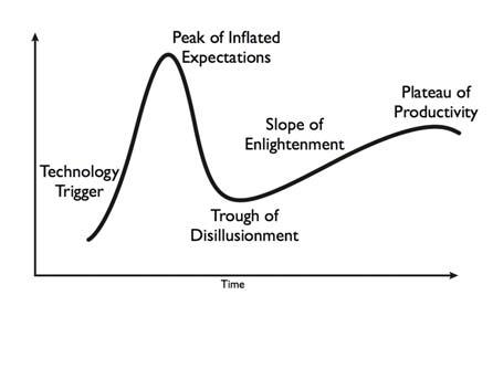
focus our efforts, we felt that success would follow. Building upon this first success, we could move forward with implementation on a broader scale.
In the early 1960’s Everett Rogers developed a diffusion model that describes the adoption and acceptance of new technology in society [5]. Geoffrey Moore improved upon this model by recognizing that there can be a chasm between the early adopters (visionaries) and the early majority (pragmatists) (Figure 2) [6]. One of the main driving forces of our efforts was to reduce the width of this chasm between the VFG and the rest of the organization as early as possible, by convincing the majority of the OPP staff to accept and then implement these changes within their existing processes.
These two change models are often superimposed. The chasm typically lines up with the downward slope of the hype cycle. If the chasm is not bridged, the trough of disillusionment grows deeper. Change then loses momentum and is never adopted by the majority of staff. We determined that our initial pilot study would focus on a group that was relatively small, technically savvy, and was desperately seeking change to improve their
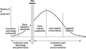
performance. This group would become Penn State’s catalyst for change.
After understanding how change and implementation of new processes can fail, we searched for a method to assure that the changes we were proposing would be successful. The ADKAR model of change management was developed by Jeff Hiatt of the Change Management Learning Center [7]. The model is used to determine resistance to change transition through the change process and encourage a change oriented philosophy. The five elements of the model are [7]:
Awareness of the need for change
Desire to make change happen
Knowledge about how to change
Ability to implement new skills and behaviors
Reinforcement to retain change
As we moved forward with our strategies for BIM implementation, we realized we had to develop both an internal and external pressure for change, in order to be successful. With accelerated project schedules, the demand to do more with less, and the realization that there were inefficiencies within our information exchange processes, it was easy to see that implementing BIM through the project life cycle could provide a tremendous benefit. As we spoke with various departments within OPP, we found that this was a shared vision. The desire to make the appropriate changes to existing processes became apparent and was reinforced during our meetings.
The goal of the VFG was to share the knowledge that we had developed so all OPP departments could understand the new process. The process we focused on first was information transfer. We developed strategies for presenting these process problems and working with the groups for solutions that integrated change into their current practices.
As we began to develop strategies to bridge the chasm in the diffusion model, we came to realize that it was very easy to motivate the Innovators and Early Adopters. These are generally highly motivated individuals that are looking to technology to improve information flow and assist with work tasks.
The Pragmatists, Conservatives, and the Laggards as described by Rogers [5] and Moore [6] were a different challenge. These groups required a different approach and often require manipulation of their behaviors to bring success. We paid particular attention to the ADKAR model when we were
planning to meet with these groups. Reinforcement and recognition of even the smallest changes became important and integral to our success.
Our strategy to implement BIM at OPP was simple - divide and conquer. We did not want to try to enforce a broad strategy across all of OPP immediately. We had a focused solution: implement BIM in a division that had a very interested Director and a large number of staff that could be classified as Innovators, Early Adopters and Pragmatists.
OPP is comprised of eleven divisions; each is headed by a Director. The VFG met with each Director individually in order to determine our earliest successes were to be found. We focused our discussion on the information transfer from design to construction and then into operations. Early experiences indicated that the introduction of models focused conversations on technology and not process. There was no mention of models, software programs, or other “Hollywood” BIM solutions. We wanted to understand how each division received information during the design and construction process; how they used that information; how the information was tracked, verified and maintained; what workflows they used; and how these were modified to handle the existing information flow. We talked about BIM as a facility lifecycle tool and discussed how better and more timely information would help their division. We asked about their key staff and identified Innovators and Early Adopters.
Following these department meetings, it was necessary to prioritize the areas of integration. The VFG found that two departments, Design and Construction and the OPP Work Control Center, were the most appropriate for the initial strategy development. Having the most experience with BIM from previous University projects, the Design and Construction Division provided the best opportunity for success. This division is responsible for project management for new construction and major renovations. They had been exposed to BIM in its earliest stages of project implementation. This division was also responsible for developing, collecting and transferring information developed during construction projects to the other divisions.
The OPP Work Control Center (WCC) plans, prioritizes, and schedules maintenance, repair, and renovation work and capital projects for Penn State. Responsible for approximately 50,000 facility assets, the WCC focuses on preventative, corrective, and emergency maintenance work orders. This department is one of the primary receivers of information generated from design construction projects.
As part of the first phase of our BIM implementation, we analyzed existing systems, workflows, processes and procedures related to information exchanges from construction to facility management. We developed the BIM to facility
management integration strategy using focus groups from our internal divisions, consultants, construction managers and our design, construction and asset management software vendors. We initiated several small pilot proof-of-concept studies to develop a prioritization for potential integration strategies and methodologies. These methodologies focused on how each group moves and uses information within itself and with each other.
We quickly realized that within each division, the information flow and processes had developed over time to be optimal for the tasks performed within the group, but the transfer of information across divisional boundaries was not optimized. The process improvements focused on timely transfer of information between groups. The information flow was primarily directed from Design and Construction to the WCC to adequately plan and perform preventative maintenance work and asset management before the facilities came on line. Through our work sessions, we also established the need for the WCC to be involved in the early phases of design and construction. Their knowledge about existing systems helped ensure efficient and economical designs and avoided common maintenance design issues.
The efforts in aligning BIM with facility management processes were focused on: providing asset information, reducing the cost of asset management, providing visibility of operator data requirements, and delivering feedback on building performance. These four areas revolved around collecting, verifying, and transmitting data so asset management could be performed faster, at a lower cost and with higher quality than ever before.
We had immediate success on several pilot projects and we began our first truly integrated project on the newly constructed Pegula Ice Arena. From the first meeting with the design and construction team, we drove the philosophy of lean delivery of project information. We developed a project BIM execution plan that stressed having the right information, entered into the right software, at the right time, by the right person. We provided the ability to see, analyze, use and modify the data from both a design and asset management perspective. At any time, the designers, construction managers and facility managers had access to the latest attribute information and geometric data.
In the eight years that we have been using BIM, we have successfully completed 25 projects totaling more than 1,000,000 SF of new and renovated buildings. These buildings include high tech research labs, classroom and office buildings, hospital, cancer research lab, sporting venues, and
student housing. Our successes have built with each project. We have now fully implemented our information transfer protocols for major building systems, equipment is tagged when it comes on site, and our facility managers have asset information immediately. We have reduced construction and change order costs with better coordination during design and pre-construction. Our owner generated change orders have also been reduced by using advanced visualization techniques to allow our customers to “walk through” the building during design.
While many owners would be quite happy with these results, we believe that we are still on the Slope of Enlightenment. We continue to seek and develop new uses for BIM during all phases of the project and facility life cycle. Our success has been built on an in-depth understanding of the social impacts of BIM, developing a strategy for change management and carefully planning the execution of the implementation.
[ 1 ] Gallaher, Michael P., Alan C. O’Connor, John L. Dettbarn, Jr., and Linda T. Gilday, “Cost Analysis of Inadequate Interoperability in the US Capital Facilities Industry”, NIST Report GCR 04-867, August 2004.
[ 2 ] Teicholz, Paul, PhD, “Labor Productivity Declines in the Construction Industry: Causes and Remedies”, AECbytes Viewpoint #4, April 14, 2004. www.aecbytes.com
[ 3 ] Teicholz, Paul, PhD, “Labor Productivity Declines in the Construction Industry: Causes and Remedies (Another Look”, AECbytes Viewpoint #67, March 14, 2013. www.aecbytes.com
[ 4 ] Gartner Inc., Research Methodologies, “Hype Cycles – Interpreting Technology Hype”, http://www.gartner.com/technology/research/ methodologies/hype-cycle.jsp
[ 5 ] Rogers, Everett M. (1962). “Diffusion of Innovations”. Glencoe: Free Press.
[ 6 ] Moore, Geoffrey. “Crossing the Chasm: Marketing and Selling High-tech Products to Mainstream Customers” (1991, revised 1999, 2000, 2001, 2002) New York: Harper Collins
[ 7 ] Hiatt, Jeff, "ADKAR - A Model for Change Management”, Change Management Learning Center, http://www.change-management.com/
Headcount Engineering Services, Balbriggan, County Dublin.
E-mail: 1gary.mcelroy@headcount.ie 2philip.tyrrell@ headcount.ie
Abstract – While current practises of design, control and management on projects are effective. The intention of this paper is to highlight and the need for discussion and the requirement for a BIM model custodian throughout the BIM project lifecycle and in particular on the part of the client.
Keywords BIM, model, custodian, lifecycle
Previous experience working on BIM projects has taught us that the 3D model complete with information must be delivered to the client in a validated and credible format.
As BIM is maturing in Ireland the sustainable benefits are being realised by all entities. The adoption of a “Data Standard” across all discipline entities including the “client” is becoming more of an obstacle than a value at the backend of the BIM life cycle.
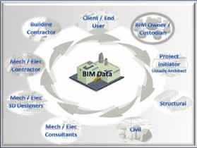
A client’s expectation when adopting BIM on a project can sometimes enter a grey area of delivery and usability at handover stage. Most clients will not have the software or hardware required to extract information from the model and will require the services of the general contractor into the future. This means the link between the general contractor and the client must remain even if commercially, the project ended badly.
It is vital that a model Custodian acting as an external repository on behalf of the client should be included in the roll of players in the BIM lifecycle of a project.
A typical BIM lifecycle is a design cycle that spans from the concept stage of a project through to occupation of the development by the client and beyond into the future. It is essential that every BIM project have an agreed lifecycle by all entities prior to “Start”. The position of the custodian should be “as an honest broker” between the client and the project initiator as a means to validate the project setup on behalf of the client.
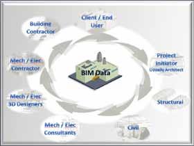
BIM being a relatively new method of project design it is understandable that there is no regulatory body in Ireland standardising the inputs and outputs of a BIM model. A custodian has responsibility for ensuring the model and its information is kept in a “central data store” in a secure location with access to information available to only approved vendors or personnel. The requirement that the model is always kept up to date with current licence agreements and subscriptions.
The value proposition of the custodian will be reflected in the cost savings achieved at the end of the project and data information control into the future and in the improved usability of the data. T he requirement for the custodian to manage the model into the future is purely designed with the client ownership in mind.
One of the great advantages of using BIM on a project is the “future use” of the information and the availability of a virtual building at the touch of a button.
An issue which has arisen on every BIM project is the user friendly operability of the model and information that the client user is left with. Most clients are not “BIM literate” or “BIM prepared” and therefore would not have the infrastructure in place to accept the model and its information in its raw format. The availability of review software such only enables an end user to review and view their model but not extract information in a required format. Do they invest in software costing €0,000’s? or do they rely on a 3rd party model custodian with BIM capabilities to act on their behalf, away from other entities?
To achieve the goal of BIM compliance, a strategy must be agreed by every entity involved in the BIM community. Each entity should nominate a BIM representative to liaise their requirements to the owner with a clear and precise request of what they wish to achieve from the model and its information.
The strategy should be agreed and documented by a review board with experience of using BIM on large scale projects in not only building projects but in plant and manufacturing projects also. The custodian is best suited to control the strategy as BIM in Ireland is moving at a pace that without this some
companies will get left behind in the compliance requirements and there is a risk they will take shortcuts.
In the UK at present there is great emphasis on the standardisation of BIM, and in particular the “Data Exchange Protocols”. This is something we need to investigate as BIM grows and develops in Ireland.
(Ref. 1)
Regardless of whichever path we choose to take, the model Owner / Custodian will be heavily involved in that destiny.
1.) AEC (UK) BIM Protocol Project BIM Execution Plan
BIM projects and intelligent 3D models require a level of control and management by an owner / custodian through the full BIM lifecycle. A central data management system ensures the BIM project is organised and controlled future requirements by a client / end user. The data management / control and of the 3D model and the inputs / outputs are what makes BIM work!
Collaborative Construction
Cincinnati, Ohio 45202
E-mail: JamesLSalmon@gmail.com
Abstract The existing built culture in the built industry is fragmented, adversarial and paranoid. It cannot support the innovative new technologies and business processes necessary to compete in the knowledge economy. Building information modelling (BIM) and integrated project delivery (IPD) are two innovations that must be deployed effectively in the built industry to compete in the emerging knowledge economy. An integrated, collaborative and cooperative culture, supported by a new legal framework, will be required to deploy BIM & IPD. This paper explores BIM, IPD, built culture and offers a new legal framework supportive of those innovative processes and a new built industry culture
Keywords Legal framework supportive of BIM and IPD.
Owners of facilities and supporting infrastructure have, throughout history, demanded built industry professionals deliver facilities and infrastructure faster, better and cheaper. In response, built industry professionals advised owners you can have any two (2) but not all three (3). Now owners want greener and better facilities and infrastructure faster and cheaper.
Tasked with hammering a round green peg through a square brown hole, the built industry has begun to flirt with virtual planning and design tools on the front end, lean construction, supply chain and logistics processes during construction and a myriad of advanced software tools that promise increased efficiency in operations and facilities management, during operations and maintenance. Success, however, remains elusive.
The financial crisis dried up easy money for facilities and infrastructure projects. Meanwhile, advocates of sustainability continued to demand greener projects with smaller carbon footprints, lower energy costs, reduced water consumption and less environmental impact generally. Fiscal hawks and environmental activists squared off in the public arena. Initially, the environmentalists prevailed.
Governments adopted an array of policies intended, among other things, to ensure green / sustainable public sector projects. Financial limitations intruded, and costs again took center stage. The round green peg of sustainability, aka better greener facilities and infrastructure met the square brown hole of financial reality represented by project budgets and schedules.
Planners, owners, designers, constructors, trade contractors, suppliers, operators, maintenance personnel –and other stakeholders in the built industry – have all taken turns trying to pound splintered round green pegs through square brown holes. Most fail, succeeding only in wedging the green pegs ever more tightly in the hole. The splintered green pegs, virtually unidentifiable at this point, confirm few in the built industry can define “green” and fewer still actually deliver greener better and more sustainable facilities and infrastructure. Typical service providers, armed with complex green specifications, a narrowly tailored scope of work, and
other contractual mandates, don their blinders and deliver services and materials with no regard to sustainability, long term consequences or adding value for the owner, The over riding concern is the bottom line. Existing legal agreements reinforce the supremacy of cost over quality, schedule and sustainability on most projects.
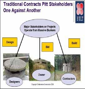
Sustainability, outside of being perceived as raising costs, is either ignored or given lip service only. Few stakeholders ever peek over the cost horizon, much less analyze or calculate the long term value of sustainable solutions. Few tackle these issues substantively because doing so reveals wicked problems for which few in the industry have solutions. That's because traditional procurement tools and processes offer little hope to stakeholders facing these wicked problems.
Design-Bid-Build, the most widely used procurement model on the planet, purports to leverage competition among bidders to lower costs. Competition on cost, however, fails to create value. Design-Bid-Build routinely fails to deliver better greener facilities and infrastructure faster or cheaper. Professional service providers competing on price rarely have the ability to deliver greener facilities and infrastructure either.
Failure of the model to deliver results deters its use little, especially in the public sector where it is often mandated via antiquated procurement laws and regulations adopted long ago. Owners, seeking the Holy Grail of better greener facilities and infrastructure faster and cheaper draft complex Requests for Proposals (RFP). Emerging briefly from their bunkers – where they silo their own key personnel – owners toss the completed RFP over the wall to the planning and design community.
Planners and designers pick over the RFP then submit bids. Assuming, incorrectly, low cost equals best value, owners select planners and designers on the basis of cost then sign agreements to fix those costs. The planners and designers retreat to their bunkers to complete the design. Once the drawings are complete – a euphemism if ever there was – they are tossed over the wall to the general contracting community and the low cost bid process repeats itself. The charade of low bids continues with specialty designers, owner's consultants, trade contractors and others signing agreements until the owner, the designer and the general contractor have all executed dozens of disjointed legal instruments.
Those disjointed instruments, cannibalized, revised, restated and patched together from agreements drafted years ago by dead lawyers, to comply with the antiquated laws and regulations mentioned earlier, prop up the Design-Bid-Build delivery model which is antithetical to the collaborative, cooperative and integrated spirit required to obtain greener and better facilities and infrastructure faster and cheaper.
The Design-Bid-Build delivery model emerged from and perpetuates a fragmented, adversarial and paranoid built industry culture. That culture, marked by CYA letters, inter-disciplinary disputes and bitter scorched earth litigation tactics consistently produces low quality facilities and infrastructure over budget and over schedule. Thus, the most prominent and prevalent procurement model on the planet, Design-Bid-Build provides a virtual road map to failure. And owners, especially public owners, cling to that delivery model like it's the last life-vest on the Titanic!
Ironically then, owners who want better, greener faster, cheaper get dirty low quality facilities and infrastructure slower and at a higher price by using Design-Bid-Build. No wonder it is so popular! To procure greener, better facilities and infrastructure faster and cheaper we must radically revamp built industry culture and the basic built industry delivery model. This requires the built industry adopt a collaborative, cooperative and integrated culture and deploy new generation technologies, business processes and legal frameworks that support and enable such a culture.
The Building Information Modelling (BIM) and Integrated Project Delivery (IPD) are two innovative processes that underpin the move towards a collaborative, cooperative and integrated built industry culture. BIM resources abound, but one of the best is the Building Information Modelling Planning Guide for Facility Owners published by Penn State's Department of Computer Integrated Construction. Stanford University's Center for Integrated Facilities Engineering also produces excellent materials and the UK Government has commissioned the creation of a wide range of BIM oriented tools and guidelines.
Readers interested in learning more about IPD would be well served by reading Integrated Project Delivery: The Game Changer, a sixty (60) plus page legal analysis of that delivery model presented to the American Bar Association's Forum on the Construction Industry in April 2012 and IPD Teams: Creation, Organization and Management, a substantive paper on the topic authored by Howard W. Ashcraft of Hanson Bridgett in late 2011.
BIM and IPD, and the tools whereby those innovative business processes are adopted, adapted, deployed and implemented, are critical to the development of a new built culture and a new generation legal framework that supports such a culture. None of this can be accomplished in a vacuum. Simultaneous adoption of these various tools and processes creates synergies and it's that process that must be undertaken, in education, on project sites, in board rooms, in planning meetings and throughout the built industry if we are to change our fragmented, adversarial and paranoid culture into a collaborative, cooperative and integrated one.
Major To successfully deploy and leverage BIM, IPD and other innovative technologies and business processes exiting built industry culture must change. Innovative processes like BIM and IPD succeed in integrated, collaborative and cooperative cultures. Developing such a culture in the built industry requires the existing legal framework – upon which the industry's adversarial, fragmented and paranoid culture rests – be torn down and rebuilt.
The classic arch provides a convenient conceptual frame of reference for understanding how BIM and IPD fit together, and how new generation legal instruments support and enable both. Paint an image of an arch in your mind and imagine the blocks on the left side of the arch to be blocks carved using virtual planning and design tools, aka BIM. Further imagine the blocks on the right side of the arch to be carved utilizing lean business processes popularized in the US by Toyota, via the process commonly referred to as Six Sigma. Having built the arch in your mind, imagine supporting the two halves of the arch structure without a keystone. That's what happens when an owner demands BIM and / or IPD but fails to adopt an integrated legal instrument to serve as the keystone that supports those innovative processes. Integrated agreements support and enable BIM on the one hand and lean construction and business processes on the other, providing structural integrity to the arch. Building arches on project after project builds the skills required to successfully deploy BIM and IPD. Crafting, negotiating and implementing such integrated agreements hone an integrated team's collaborative skills and increase the efficiency with which BIM and IPD are deployed.
The arch image helps visualize the concepts.
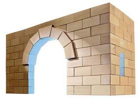
Today's built industry exists within in a fragmented, adversarial and paranoid culture. Participants plan, design, build, operate and maintain facilities and supporting infrastructure from a series of silos or bunkers. As noted earlier, see the first image above, the most common delivery model in the built industry, Design-BidBuild, reinforces those cultural norms, as does the traditional legal framework within which the built industry functions and within which the Design-Bid-Build model delivers projects.
Fragmentation, adversarial behaviour and paranoia – among other things – derail efforts to deploy and utilize BIM and IPD effectively. Advocates of BIM and IPD recognize this and have begun to focus on the “Human Side of BIM” in presentations and at events. Too often, however, such efforts focus on symptoms and ignore root causes. Identifying and understanding cultural barriers to BIM and IPD empowers organizations to deploy industry innovations more effectively. Fragmentation, adversarial behaviour and paranoia have been explored elsewhere. Here, the scope and nature of a new legal framework will be explored.
The existing legal framework, as described above is broken. An effective and modern legal framework would recognize and value collaboration and cooperation among integrated teams. Such a legal framework should arm smart leaders with timely and accurate data and empower them to make timely, high quality decisions throughout the life cycle of a facility. Further, a robust and fully integrated legal framework would connect facilities and decision makers associated with facilities to data related to infrastructure, supply chains, local governments and other key sectors that impact the business purpose of the facility.
The image below depicts one vision for such a framework. The concept treats data like the water that flows through an aqueduct. Conceptually the structure of the aqueduct, including the series of arches that support the aqueduct, and the trough that carries the water, serves as the legal framework that supports intelligent dispersion of data. Just as ancient aqueducts dispersed water to multiple users, the correct legal framework can support disbursement of BIM data – and other Big Data – among key built industry stakeholders.
Owners need to create programs to support integrated procurement, integrated project delivery and integrated operations and maintenance. Those programs relate, respectively, to the conception and planning phase, the design and construction phase and the operations and maintenance phase of a major facility. Developing, deploying and utilizing effective integrated legal agreemen ts at each phase – the individual arches in the image above – enables owners, and the integrated teams they form, to leverage BIM throughout the life cycle of the

facility. That process, in turn, enables and is enabled by the new legal framework, depicted by the aqueduct as a whole.

Traditional legal frameworks ignore the long term value of digital assets. The new legal framework described above not only recognizes the value of digital assets, but actually provides incentives to preserve and enhance the value of those digital assets. BIM, or good BIM, gives rise to high quality digital assets. An effective BIM integrates and leverages the digital assets that accumulate over the course of the project. Think of the initial BIM data associated with a project as a tea cup of information.
The initial teacup of information grows into a gallon jar as site assessments are completed etc., and later becomes an enormous tank containing an incredible amount of project related information as actual planning and design documents are completed. By the time the data arrives on the project site no single person could ever consume it all.

Stakeholders involved in planning, design and construction cannot attach a hose to the bottom of the tank of data and ever expect to consume all that information. Nor should they. They need to selectively pull the information that empowers them to make intelligent, timely decisions, relevant to their scope of work. The new generation legal framework supports and enhances those efforts.
Traditional legal agreements fail to address the flow of data through the aqueduct and further fail to address the rights and responsibilities of the users of such data once it arrives on the project site. The new generation legal framework reflected in the series of arches, all of which support one another, and the aqueduct through which accumulated data flows, will empower built industry stakeholders to create, share, access and leverage project related data more intelligently and more efficiently. The collaborative, cooperative and integrated built culture required to construct such a legal framework serves as the mortar that binds the blocks in place. The individual blocks, carved by specialists of all kinds are supported by keystones, integrated legal agreements used to procure specific aspects of the project at various phases.
For example, project managers need to data related to constructability, schedule, supply chain logistics, clash detection etc. etc. Risk managers have a different set of concerns and need access to different data. The chief financial officer, director of human resources and vice president of facilities each access discrete information resources and require different data at different moments in time. In short, stakeholders who leverage BIM do so by accessing and filtering the right data at the right moment in time.
A legal framework that supports such efforts is needed. And that legal framework must support and enable not only BIM and IPD but desired cultural characteristics as well.
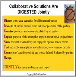
Negotiating and implementing collaborative solutions of the kind necessary to formulate such a legal framework is no small task. But mechanisms exist which support the effort. Integrated teams that develop collaborative solutions together enjoy success over time. The image below lists steps in the processes whereby an integrated team can jointly digest and implement collaborative solutions.
As more and more stakeholders in the built industry recognize the value of BIM and IPD more and more of those stakeholders attempt to adopt, adapt to and implement BIM and IPD in the real world.
Those efforts, typically undertaken by A Teams filled with BIM Evangelists and IPD Advocates, tend to be very successful. However, when the B Team / Second String / Replacement Players sub in for the A Team on subsequent projects implementation becomes a lot tougher.
The crafting, negotiation and implementation of an integrated legal agreement qualifies as a collaborative solution an integrated team DIGESTED Jointly. That exercise, undertaken quite naturally by the A Team on many projects is something the B Team and other less experienced stakeholders should welcome as a mechanism for learning the process and building team trust. Advanced workshops of that kind should be part and parcel of the new generation legal framework contemplated here.
How then, do we create a Smart Built Culture? The constant lament is, “How do we change the culture of the built industry?" Well, it's not easy. But collaboratively pursuing solutions to the vexing and wicked problems faced by the built industry is a good place to start. Advocates of BIM and IPD have developed workshops, legal instruments and programs that support stakeholders interested in deploying BIM and IPD in the real world. The resources are there, those seeking support just need to take advantage of them.
The bottom line? Changing culture requires the industry adopt a collaborative mind set. Stakeholders must seek to collaborate, and seek to work together on a cross-disciplinary basis. They must then circle back around and collaborate some more. Designers who create the initial design intent oriented BIM typically know nothing about the needs of constructors and or trade contractors. Those stakeholders need to educate the designers in that regard. Too often designers toss design models over the wall to the constructors with no real communication. But this behaviour is supported and even encouraged by the existing legal framework prevalent in the built industry today. The new legal framework should be designed to encourage rather than discourage collaboration.
Traditional legal agreements, used to support Design-Bid-Build, create Humpty Dumpty BIM; BIM tossed over the wall that breaks into a thousand pieces.
In the current work flow too many constructors simply sweep up Humpty Dumpty's remains, dump him in the waste bin and start over. They take 2D drawings and set out to re-create the wheel by modeling everything in the 2D drawings again, from scratch. Another version of the Humpty Dumpty game takes place when the contractors toss requests for bids over the wall to their trade contractors / subcontractors. The BIM at that point has become even larger. Again the prevailing legal framework often mandates such action.
At commissioning and hand off to the owner the scope and nature of the information embedded in the BIM data has expanded exponentially. Shop drawings - hopefully in a BIM compatible format - delivered by dozens of trade contractors / SMEs add thousands of gallons of information to the tank each week. It becomes a vast reservoir of data, much of it completely irrelevant to the day to day operations and maintenance tasks confronted by the owners’ facility maintenance personnel and those in charge of operations. At that point, the entire team - including the construction manager responsible for hand off - must focus, like lasers, on the business purpose of the facility.
Unfortunately, constructors don't often hand off useful digital assets to owners. And existing legal instruments don't require them to do so. Instead, owners typically receive a box of BIM Blocks or a BIM encoded on a Braille Rubik’s Cube. Owners lack the in-house staff to rebuild the facility from the Box of BIM Blocks or to decode the dozens of BIM software programs used to author the BIM encoded on the Braille Rubik’s Cube. In short, owners cannot make heads or tails of the digital assets received. So once again, the wheel is recreated.

Clearly, the built industry's existing procurement methods, delivery models and legal framework are broken. Further, the industry is swimming in a giant ocean of change that's slowly being brought to a boil by emerging innovations. Don't be the frog that thinks the water is just fine!

The first step in any recovery program is admitting there is a problem. The built industry must take steps to correct the problem. This can be done, but the road to recovery is long and hard.
An integrated legal framework that supports and enables collaboration, cooperation and integrated delivery of intelligent digital assets throughout the life cycle of the facility would ameliorate much of the waste and madness. Companies that recognize BIM as the SMART Game Changer it is will learn to leverage it and will have great success. Those who don't won't.
E-mail: 1david.ward@rpsgroup.com
Abstract If the AEC Industry in Ireland is to take advantage of Building Information Modelling (BIM) it must embrace both the technology and new ways of working. Collaboration is essential if design, construction and operation teams are to address the entire life cycle of the infrastructure product. Approaches that focus solely on technology will fail unless organisational and person factors are considered integral to the implementation process. The ‘Planning and Implementing Effective Collaboration in Construction’ (PIECC) framework can facilitate the strategic planning and implementation of effective collaborative working policies and practices. This paper investigates if this framework which incorporates a 'technology process flow' is beneficial to the architectural, engineering and construction (AEC) Industry when preparing and implementing inter-organisational projects utilising BIM. It explores factors influencing collaboration within and between organisations and highlights the ability of social capital to promote collaboration within teams. It assesses the applicability of the framework in Ireland. A qualitative research project was carried out to explore the experience of AEC professionals. Participants were selected using purposive sampling. Semi-structured interviews were conducted, exploring participant’s experience of key themes influencing collaboration identified in the framework. Interview transcripts were coded according to central themes in the framework. Results indicate that AEC professionals across different sectors face common challenges when working with multi-organisational teams. Participants highlighted the importance of relational factors influencing social capital and collaboration. PIECC framework accurately reflects the factors influencing collaboration in the Irish sector. Participants felt that the PIECC was a useful tool to facilitate the decision making process within collaborative teams and could be utilised to implement a BIM process across the AEC industry.
Keywords BIM; Collaboration; PIECC framework; Social Capital; AEC.
There is global recognition that the AEC industry must embrace new and better ways of working, if it is to remain competitive and meet the needs of its clients in future. In May 2011 Paul Morrell the United Kingdoms (UK) Government Chief Construction Advisor recommended that all UK construction projects of £5 million and over be delivered utilising collaborative 3D BIM [1] Morell gave a very apt warning to the AEC Industry, adopt BIM or be ‘Betamaxed out’.[2]
Modelling technology has the potential to revolutionise the AEC Industry increasing productivity and reducing costs but the full benefits of this technology can only emerge if the AEC industry find a way to successfully collaborate.
Project delivery in construction is highly dependent on the effectiveness of the project team. The traditional competitive behaviour, disjointed and ‘siloed’ nature of the industry has created problems causing conflicts and cost overruns. Collaboration has been identified as a method to reduce these effects
The Architectural, Engineering and Construction Industry (AEC) is highly multidisciplinary, comprising diverse organisations which may be grouped into Clients, Consultants and Contractors. These specialist professions must collaborate to efficiently and effectively custom design, engineer and construct projects. [3]
Both the UK and Irish AEC Industries have parallel cultures, equivalent professional qualifications, apprenticeships and training, they utilise identical or corresponding design codes, standards, and products. Many of the Contractors,
Consultant and Client Organisation operate concurrently in both jurisdictions.
The industry has a fascinating history of trying to achieve the aim of collaborating to custom design, engineer and construct projects. Back in 1840 with a budget of £700,000 and project programme of six years the ‘New Palace of Westminster’ the current British House of Parliament began work to the design of the architect Charles Barry. The construction involved many of the day’s major contractors. It used new engineering techniques and machinery as well as the skills of hundreds of different traditional craftsmen and a large manual labour force. Today this building is one of the most recognisable and famous buildings in the world, but the project did not run smoothly, there was dispute after dispute starting even before construction began. There were arguments over the initial design competition; arguments over the estimates and fees. There were problems with procurement of the specified stone. The heating and ventilation designer fell out with the architect, apparently becoming mortal enemies. A foreman swore at a mason causing the masons to strike for 30 weeks. In the end it took 30 years and cost over £2 million (circa £500 million in today’s money), similar disputes and cost overruns plagued the industry throughout the nineteenth century and throughout the twentieth as well. [4]
So as far back as 1840 it could be said that AEC Industry was ineffective, adversarial, fragmented and was incapable of delivering to its clients expectations and unfortunately 150 years later Michael Latham came to the same conclusion in his industry wide review.[5]
In all Latham made 53 recommendations, which incorporated measures to increase efficiency and replace the bureaucratic wasteful adversarial atmosphere present in the majority of construction projects, he urged reform and advocated Partnering and Collaboration by organisations within the construction sector. [6] This report and the following years Egan report (1998) have been extremely influential within the industry, initiating numerous reviews and projects and has resulted in the establishment of industry change organisation such as Design Build Foundation in 1997, Construction Best Practice Programme, the IT Construction Best Practice Programme, Movement for Innovation and Construction Excellence.
Regrettably some of the criticism and some of the recommendations of these reports have been made time and time again over the previous 100 years with little change, history has again repeated itself when the New Scottish Parliament with an initial budget of £40 million ran 3 years over programme and had an eventual reported cost of £414 million.[4]
So today in the United Kingdom (UK) the AEC Industry is worth somewhere in the region of £110 billion per annum1 equating to approximately 7% of the UK’s Gross Domestic Product (GDP). This figure would be much more if the whole life contribution through planning, design, construction, maintenance, decommissioning and reuse was included. [7]. In Ireland, it has fallen from its peak of €38.5 billion (24% GDP) to an estimated value €7.5 billion in 2011, circa 6% of Irelands GDP. [8].
Because of this high value the UK Government in its ‘Plan for Growth’ published in 2011 state that a successful construction industry is vital for sustainable growth and recognise that building and maintaining infrastructure underpins a strong growing economy.
To enable this the UK governments aims to remove ‘obstacles to growth and create a business environment in which companies in the construction sector have the confidence to invest’ by reforming the way in which it procures public sector construction and infrastructure it hopes to create new models of procurement which will reduce costs by up to 20 per cent. This enhanced business atmosphere will foster greater ‘supply chain integration’ and develop innovative processes. [7]
They started by devising a hypothesis “Government as a client can derive significant improvements in cost, value and carbon performance through the use of open sharable asset information” and a number of tests to guide and validate its wor k. They identified that if the AEC Industry embraced this new process/technology improved supply-chain integration could be generated with the resulting performance improvement greater project ‘certainty’ and reduced risk. These benefits of improved integration have been identified in numerous official and semi-official reviews over the last sixty years Murray and Langford’s paper ‘Construction Reports 1944-1998’ provides a useful summary of these investigations and reports, that all identify the dislocation between design and construction as a ke y issue and urges closer integration between team members.[5][9] [10].
One of the main benefits of successful integration of the supply chain is accurate, effective flow and intelligent use of Information which BIM b y requiring interoperability of information will encourage.
In addition to the benefits achieved by the supply chain integration, BIM also adds a post construction benefit through Facility Management. The model provides valuable information on space utilisation; running costs and energy /carbon reduction. This can be leveraged throughout the life of the building providing valuable information to
enable sustainable reuse of materials plan at end of the assets useful life. [11]
Building Information Modelling is a digital representation of physical and functional characteristics of a facility creating a shared knowledge resource for information about it. This forms a reliable basis for decisions during its life cycle.[12].
The data generated contains multiple detailed dimensions, component placement, material specification, structural performance, fire rating, U values, carbon content (both embedded and operational), cost, maintenance schedules and performance etc. In effect, the structure is built virtually using these exact data-rich objects from which plans and drawings can be generated. It is a distinguishing feature of BIM that no traditional ‘drawings’ are involved in the creation of the model.
BIM has the benefit of being a collaborative process with the parties working together at an earlier stage. [13].Transparent and common data sets for calculations are generated for use during the project life cycle. This has the added benefit of reducing the risk of information being misinterpreted by individ ual team members and the breakdown of trust that can occur as a result of this.[14], [15], [16]
If the AEC industry is to take advantage of BIM, stay competitive and meet the needs of its ever demanding clients it must not only embrace the new technology but also embrace new ways of working. This requires a move towards collaborative working and its associated fields; concurrent engineering and lean production. [17] “Collaboration generally refers to individuals or organisations ‘working together’ to address problems and deliver outcomes that are not easily or effectively achieved by working alone.
Collaboration is essential if design, construction and operation teams are to address the entire life cycle of the infrastructure product and take account of the primary functionality but also productivity, buildability, serviceability and even recyclability [18]
Most of the previous work on collaborative working focuses on technological solutions such as extranets, modelling and visualisation software, knowledge management technologies and systems. [6], [19], [20]
Approaches that focus purely on information technology will fail, unless organisational and people issues are considered as part of the implementation process.[21], [22]
Moving to BIM necessitates profound change in common work processes, inter-organisationally as well as intra-organisationally. Changes related to staffing, training, project team configuration and project infrastructure impact previously established processes. This process change will require new roles and responsibilities to be established as well as new standards and management models. On a cultural and political level, some staff will find it easier than others to embrace the new possibilities. [23]
Collaboration between organisations and individuals in the AEC Industry implies moving from an informal to a formal relationship. It requires a conscious effort and continuous negotiation on behalf of all of the team members to achieve the aims or goals of their project.
Collaborative relationships facilitate the development of social capital which in turn increases the efficiency of the collaboration. So building collaborative relationships requires the resource o f social capital, both of which are prerequisites for inter-organisational team action.
Social capital is a concept that originated in sociological science. In the past twenty years it has gained wide acceptance and has been further developed in other disciplines. Economic theory no w recognises the importance of the web of social relationships that influence individual behaviour and thereby affect economic growth. The essential idea of Social capital is that relationships of sympathy/obligation, including trust empathy and rapport, influence nearly every interpersonal transaction. Its application is multi-disciplinary and it operates across diverse fields to the very creation of civil society. [24], [25]
It can be defined as a person or group’s sympathy, or sense of obligation towards another person or group, which may produce a potential benefit, advantage or preferential treatment for others beyond that which might be expected in an exchange relationship. It is ‘ Service potential derived fro m social relationships’ [26]
Social Capital is the result of the formal and informal networks created within project teams that allow members to trust one another. Social capital can accumulate, produce and be reproduced, can be subject to depreciation and be employed in the production of goods and services. The more social capital a project team has the more benefits ensue. [27]
Nahapiet & Ghoshal present a theory rooted in the concept of social capital that helps to explain why teams who are able to create and transfer knowledge effectively, have an advantage in the industry. They call this ‘organisational advantage’.[28] They theorize
that high levels of social capital can help to create and share intellectual capital.
Intellectual Capital is the collective knowledge held within an organisation and has a parallel with Huma n Capital which embraces the acquired knowledge, skills and capabilities that enable people to act in new ways. Intellectual capital is more than the sum of its parts. [29]
Nahapiet and Ghoshal identify Social capital has having three interrelated dimensions structural relational and cognitive.
The structural dimension includes the informal networks within organisations that enable individuals to identify others with potential resources they may not have at their own disposal. These networks identify those with relevant knowledge and help make connections, which are potentially useful as a n organisation grows.
The relational dimension is concerned with the interpersonal dynamics between individuals within a network. It addresses issues around trust, shared norms and values, expectations and identifications that are critical in developing Social capital among groups. The relational dimension recognises that Social capital is developed and fostered when individuals believe that their actions will be appropriately reciprocated and that individuals will meet their obligations. It depends on trust. A network then builds its own internal ‘formal currency’ of norms and values that are generally held and accepted. By being able to create and share relevant knowledge. The trustworthiness and commitment of others can be judged..[24], [28].
Cognitive dimension embraces a common context and language that is needed to build social capital. This is done through common objects and artefacts such as documents, procedure manuals and memos, which provide shared reference points. It can also be done by stories that convey a shared history and are transmitted and carried on by others in the organisation. Inter-organisational networks or communities of practice are instrumental in maintaining the shared vernacular or cognitive dimension.
Nahapiet and Ghoshal’s model shows how these three dimensions influence four variables that impact on the sharing and creation of intellectual capital (a) access to others for combining/exchanging intellectual capital (b) anticipation of value through combining/ exchanging intellectual capital (c) motivation for individuals to combine/exchange intellectual capital and (d) the ability of the organisation to change according to outside need. They hypothesize that increasing the amount of social capital within an organisation; it will positively influence the intermediate variables and subsequently impact on the increasing organisational knowledge or intellectual capital.
They help shape the actual terminology used by the group members and they generate and share the knowledge objects or artefacts that are used. They also generate stories that communicate the norms and values of the community and organisation as a whole. These stories allow new members to take cues from experienced personnel and facilitate the development of a community memory that perpetuates itself long after original members have gone.
Social capital facilitates cooperation and collaboration by acting as ‘relational glue’ betwee n inter-organisational team members. In considering how to identify, design and manage the dimensions of social capital, organisations that are considering interorganisational collaboration can benefit from understanding each component, its effectiveness and methods for exploiting its potential benefits. This paper will explore Inter-organisational collaborations using a detailed framework (The PIECC Framework)[30]
In order to maximise competitive advantage within the AEC Industry, Inter-organisational teams must embrace new and improved ways of working. This is dependent on the efficiency and effectiveness of the participating members of the team, which is directly impacted by the ability of team to communicate and collaborate effectively with each other.
The Planning and implementation of effective collaboration within construction (PIECC) originated from a research project undertaken in Loughborough University. Its aim is to aid project managers in construction organisations throughout the supply chain to introduce more balanced process and procedures into their projects. The PIECC emerged as a prototype decision making tool for the effective planning and implementation of collaborative working in construction projects. The PIECC was the first piece of research to utilise a systems approach and develop a high level decision making framework to optimise effective collaboration within the AEC Industry.[30]
The PIECC project aims to support strategic decision making by highlighting areas conductive to collaborative working incorporating the organisational, project and users’ needs.
In this paper we will review the validity and applicability of this framework taking into account the organisational, project and users’ needs, for use within the Irish AEC Industry.[18], [31]
A survey during the PIECC development process highlighted that for inter-organisational teams to ‘effectively collaborate’ there must be a balance of three key strategies, business, people and technology. Six key areas must be represented in the three strategies.
• Vision – all members of the collaboration agree on the aims and objectives
• Stakeholder engagement – collaboration leaders need to ensure that all key participants are consulted as to the practices employed during the collaboration.
• Trust – time and resources are needed to enable stakeholders to build trusting relationships
• Communications – a common means of communication is decided upon by all key participants in the collaboration.
• Processes – both business and project that describe to all participants how the collaboration is to work on a day to day basis.
• Technologies – an agreement on those to be used to ensure the collaboration is easily implemented and maintained.
All six areas need to be included in the three strategic areas described to have effective collaboration.
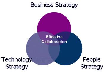
The PIECC project identified the following barriers to effective collaboration, similar areas have been identified by other authors in the research area of collaboration.[15], [16], [30], [32], [33], [34]
• Collaborating organization have different vision, mission, goals and priorities
• Organisational ‘culture’ and methods of communication are often different;
• A lack of focus and consensus on the delegation of tasks;
• An imbalance of resources – time, money, human (frequent turnover of participants) etc.;
• Confidentiality, Intellectual Property and legal considerations;
• Technological incompatibility;
• A lack of understanding of the expertise, knowledge and language of the other collaborating participants.
The PIECC Framework guides teams through four key areas by helping them to develop a joint ‘Business Strategy’, develop a ‘collaboration brief ’ for the project, help them ‘Plan the Solution’ and provide guidance to ‘Implement the solution’ into the project. This enables the development of an agreed collaboration strategy framework.
The use of the PIECC aims to improve project performance through effective allocation of resources for planning and implementation of collaboration. It provides tools and techniques to measure the success of collaboration. It acts as an educational tool to help team members to work collaboratively. It improves collaboration and communication across the project lifecycle and their associated supply chains. This results in a better project delivered to the client through efficiency savings generated through collaboration.
A diagrammatic representation of the PIECC Decision- Making Framework is depicted in Fig 2 and can be viewed at:
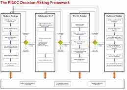
http//piecc.Iboro.ac.uk/Results/flyer_v1.
The research objective of this paper is to investigate if a collaboration framework incorporating a ‘technology process flow’ may be of use to AEC organisations preparing for delivery of Inter-organisational projects utilising BIM.
A survey of key professionals within the Irish AEC industry was developed and a series of semistructured interviews were planned. A systematic
review of the literature informed the development o f a questionnaire / topic guide for use during the se mistructured interviews. The interviewer (DW) used open-ended questions and a list of key prompts to facilitate the interview and avoid influencing the responses. Questions were grouped into key themes that linked directly to the research objectives. The guidelines for structured interviews were adhered to but allowed some flexibility in the use of nondirective prompting / probing. The schedule of questions / topics was piloted among a small group of colleagues prior to interview. Suggestions / adjustments were incorporated into the final interview protocol.)[35]
Purposive sampling was employed to target key professionals within the Irish AEC industry. This sampling approach facilitated the inclusion of senior professionals, from public, private, contractor and consultant organisations.
All participants were sourced from organisations operating within the Irish AEC Industry and were known business contacts of the author.
A series of eight semi-structured interviews were completed in 2012. This facilitated the selection of professionals from a number of different sectors and disciplines. All participants had a wide range of experience working in multi- organisational teams. Roles and years of Experience of Interviewees are detailed in Table 1.
The Coding strategy was informed by key themes identified in the PIECC framework. Participants were asked to describe their experience (both positive and negative) of these key themes. Non-directive questioning was utilised to avoid leading the interview. Participants occupying varying professional roles identified similar experiences within the Irish AEC Industry. A number of common sub themes began to emerge during qualitative analysis of the interview transcripts. These sub themes identify other factors that may influence effective collaboration within the Irish context.
All eight participants completed the interview process in full and provided detailed description of their experience of collaboration within the Irish AEC Industry. All interviewees confirmed the importance of the key influential factors identified within the PIECC framework. They provided consistent examples of experiences that support the inclusion of these key themes within the framework. All participants felt that the PIECC Decision Making Framework would be a helpful addition to their collaborative projects. No significant omissions were identified by the participants, and all felt that it would be applicable in an Irish context.
Significant quotes from participants were grouped according to central themes such as vision,
process, stakeholders, communication, technology and relationships. Emerging sub themes, included risk, trust, leadership, conflict, strategy and quality[36]. These helped to describe the experience of participants across a number of different roles and projects within the Irish AEC Industry.
When asked specifically about Building Information Modelling (BIM) 50% of participants were aware of BIM but only 25% of participants had any practical experience of using the technology. T his is unsurprising as this is an emerging technology a nd is not being utilised widely in the Irish construction industry at present.
1 Client Public 20-30 years
2 Client Public 20-30 years
3 Construction Private 10-20 years
4 Construction Private 10-20 years
5 Design Private 10-20 years
6 Design Private 10-20 years
7 Client Public 10-20 years
8 Design Private 20-30 years
During the semi-structured interviews the participants consistently identified issues that the PIECC specifically address in its protocols. The Table 2 below identifies typical quotes against the PIECC themes.
PIECC Framework Protocol topics
Establish the need for Collaboration
Develop External Business Case
Interviewee Quotes
“pulling in the same direction”; “where collaboration has been bad the project has become a painful process”
“You just can’t leave a group of companies to
Appoint Collaboration
Champion
work independently... as a client you need to play an active role to drive that through”
“A person to stand up and tell people positive things about the project to keep them revved up”; “someone has to drive it, it doesn’t just happen “; “ you need somebody there to pull the strings together”
Identify current ICT systems and technology requirement
Gain Senior Management Approval and Sponsorship
“you need a leader”;” you need a strong client who knows what they want and will manage the people under”;” a team doesn’t just build itself , you have to have the leader support it”
“technology is important for large projects, not that important for small projects, medium projects you would have to look at it in more detail to see if it’s worth it” “if information is to be transferred to you it is very useful to know how this information will come. It is vital so you can program your work to avoid issues and delays”
Allocate Resources for Collaboration
“If you require collaboration you have to manage it... you have to manage the interaction between organisations”; “you have a set of personalities that need to be managed”
Appoint and bring the collaboration management team together
“To create an environment of trust is the challenge”; “Do good relationships happen by accident? I don’t think they do, you need an effective project manager” When a project works really well it is very often down to good relationships”
Develop a shared vision
“Top up the vision make sure everyone is on the same page”; “everyone has to buy into it... it has to be in simple language”; “brief has to be very clear for the proposed roles and costs”;” 95% is clear but it’s the 5% that isn’t clear that causes the rows”
Agree Standards and Procedures
“processes are helpful to set out but shouldn’t be onerous”
Defined roles and Responsibilities
“On projects where contributors roles aren’t defined it takes longer and makes things difficult
Bring Project team together
“set clear realistic program and make sure stakeholders know about it “;”I do think getting buy in from the project team is critical”; “the biggest thin in collaboration is the trust”
Match skill to roles and Responsibilities
“all structures that work have a defined structure with a leader, workers, manager, controllers , everyone has a defined role, everyone knows who the leader is and they are actively involved in the process”
Collate and Disseminate procedures
“Kick off meetings and workshops it was made very clear what the objective were,” “new members need to be informed”
Map Project Lifecycle Processes
“you need to define the process”; “structure is the
The AEC Industry has long been known to be fractured and segmented. There is no culture of effective collaboration, with inter-organisational
teams remaining in a ‘Siloed’ configuration. A number of high profile reports including the Latham and Egan have highlighted the challenges that the industry must address in order to improve collaborative practice.[5], [9], [37]
Building Information Modelling & Management has emerged as a potential industry ‘game changer’ bringing with it the potential to influence interorganisational collaborative practices. This technology has the potential to revolutionise the AEC Industry increasing productivity and reducing costs but the full benefits of this technology can only emerge if the AEC industry find a way to effectively collaborate.
As we have seen from our findings, knowledge and experience of BIM within the Irish AEC industry is in its infancy. The UK Government has mandated the use of BIM. For Irish firms to compete in the international market they must adopt BIM practices.
In the authors opinion the Irish government should follow suit and mandates BIM. This opinion is supported by a CITA survey of Irish AEC professionals with experience of BIM where 62.2% of respondents felt the Irish Government should follow the UK lead. [38]
Implementation of BIM will lead to an increased requirement for collaboration between inter-organisational teams. This paper has highlighted that the Irish AEC industry and the UK Industry have common factors that drive or hinder collaboration. These factors can be systematically addressed through the use of the PIECC Decision Making Framework. Attention to these key drivers can facilitate effective collaboration and the growth of social and intellectual capital. The PIECC framewor k is built upon the key dimensions of social capital (cognitive, structural and relational dimensions).
The cognitive aspects of the framework comprise Vision and Stakeholder engagement. The Structural dimension comprises of Communication, Process and Shared Technology. Relational dimension of trust is central to development and maintenance of social capital which is key to interorganisational collaboration. This in turn leads to an increase project team performance with the associated cost savings generated over the project life cycle.
This paper has confirmed the existence of key factors influencing collaboration within and between organisations in the Irish AEC Industry. It has explored the experience of collaboration with key professionals working in the Irish AEC Industry and found that key influential factors are at work in the Irish and UK AEC Industries.
This paper is the first paper to validate the use of the PIECC framework in the Irish AEC Industry. This framework should be employed by the AEC Industry in Ireland when forming Inter-organisational teams. A modified framework is currently being
utilised on an intra-organisational project as part of a BIM implementation strategy across multiple business sections in a large international consulta ncy. Inter-organisational test projects should be identified to validate the framework and measure its potential affects.
[1] “NBS: BIM Roundtable Discussion.” [Online]. Available: http://www.thenbs.com/roundtable/. [Accessed: 27-Jul-2012].
[2] “Adopt bim or be ‘Betamaxed out’ says Morrell,” Building Design. [Online]. Available: http://www.bdonline.co.uk/news/adopt-bim-or-bebetamaxed-out-says-morrell/5018263.article. [Accessed: 27-Jul-2012].
[3] C. Eastman, R. Sacks, and G. Lee, “Strategies for realizing the benefits of 3D integrated modeling of buildings for the AEC industry,” NIST SPECIAL PUBLICATION SP, pp. 9–14, 2003.
[4] R. Morton and A. Ross, Construction UK: Introduction to the Industry, 2nd Edition. Wiley-Blackwell, 2007.
[5] S. M. Latham, Constructing the Team: Joint Review of Procurement and Contractual Arrangements in the United Kingdom Construction Industry : Final Report H.M. Stationery Office, 1994.
[6] P. Wilkinson, Construction Collaboration Technologies: The Extranet Evolution. Taylor & Francis, 2005.
[7] HM Treasury and Dept. for Business Innovation and Skills, The plan for growth. London: HM Treasury, 2011.
[8] DKM Economic Consultants, “The Irish Construction Industry in 2012.pdf,” Society of CharteredSurveyors Ireland, 2012.
[9] J. Egan, “Rethinking Construction - The report of the construction task force,” 1998.
[10] M. Murray and D. Langford, Construction Reports 194498. John Wiley & Sons, 2003.
[11] “Report to the Government Construction Clients Board on Building Information Modelling and Management | Policies | BIS.” [Online]. Available: http://www.bis.gov.uk/policies/businesssectors/construction/research-and-innovation/workinggroup-on-bimm. [Accessed: 04-Jul-2012].
[12] National Building Standards (NBS), “Construction Information Service Briefing Note on BIM,” Jan-2011
[13] D. Davis, “An Introduction to Building INformation Modeling,” JoBIM, pp. 16–18, 2007.
[14] Deke Smith, “BIM Journal - Not the way your parents did business transforming the construction industry,” 2007.
[15] B. Erdogan, C. J. Anumba, D. Bouchlaghem, and Y. Nielsen, “Collaboration Environments for Construction: Implementation Case Studies,” Journal of Management in Engineering, vol. 24, no. 4, pp. 234–244, Oct. 2008.
[16] V. Singh, N. Gu, and X. Wang, “A theoretical framework of a BIM-based multi-disciplinary collaboration platform,” Automation in Construction, vol. 20, no. 2, pp. 134–144, 2011.
[17] C. . Anumba, O. . Ugwu, L. Newnham, and A. Thorpe, “Collaborative design of structures using intelligent agents,” Automation in Construction, vol. 11, no. 1, pp. 89–103, Jan. 2002.
[18] M. Shelbourn, N. M. Bouchlaghem, C. Anumba, and P. Carrillo, “Planning and implementation of effective collaboration in construction projects,” Construction Innovation: Information, Process, Management, vol. 7, no. 4, pp. 357–377, 2007.
[19] L. Asprey, “Information strategies: are we aligning the business case with enterprise planning?,” Records
Management Journal, vol. 14, no. 1, pp. 7–13, 2004.
[20] P. B. Martin Sexton, “The role of technology transfer in innovation within small construction firms,” Engineering, Construction and Architectural Management, vol. 11, no. 5, pp. 342–348, 2004.
[21] R. Alvarez, “‘It was a great system’: Face-work and the discursive construction of technology during information systems development,” Information Technology & People, vol. 14, no. 4, pp. 385–405, 2001.
[22] M. Vakola and I. E. Wilson, “The challenge of virtual organisation: critical success factors in dealing with constant change,” Team Performance Management, vol. 10, no. 5/6, pp. 112–120, Jan. 2004.
[23] D. Holzer, “BIM’s Seven Deadly Sins,” International Journal of Architectural Computing, vol. 9, no. 4, pp. 463–480, 2011.
[24] E. Lesser and L. Prusak, “Communities of practice, social capital and organizational knowledge,” Information Systems Review, vol. 1, no. 1, pp. 3–10, 1999.
[25] L. J. Robison, A. A. Schmid, and M. E. Siles, “Is Social Capital Really Capital?,” Review of Social Economy, vol. 60, no. 1, pp. 1–21, 2002.
[26] L. J. Robison, A. A. Schmid, and P. J. Barry, “The Role of Social Capital in the Industrialization of the Food System,” Agricultural and Resource Economics Review, vol. 31, no. 1, 2002.
[27] M. Migheli, “Exogenous Individual Characteristics and Social Capital in Western Europe,” SSRN eLibrary, Nov. 2005.
[28] J. Nahapiet and S. Ghoshal, “SOCIAL CAPITAL, INTELLECTUAL CAPITAL, AND THE ORGANIZATIONAL ADVANTAGE.,” Academy of Management Review, vol. 23, no. 2, pp. 242–266, Apr. 1998.
[29] P. DasGupta and I. Serageldin, Social Capital: A Multifaceted Perspective. World Bank Publications, 2001.
[30] M. A. Shelbourn, D. Bouchlaghem, C. Anumba, and P. Carrillo, “A decision making framework for planning and implementing collaborative working,” in Proceedings of the Joint International Conference on Computing and Decision Making in Civil and Building Engineering, Montreal, Canada, June 2006, 2006, pp. 930–944.
[31] Shelbourn, Bouchlagem, Anumba, and Carrillo, “types of busiorganisational relationsihiops.pdf.” .
[32] T. Kvan and L. Candy, “Designing collaborative environments for strategic knowledge in design,” Knowledge-Based Systems, vol. 13, no. 6, pp. 429–438, Nov. 2000.
[33] P. McDermott, M. Khalfan, and W. Swan, “An exploration of the relationship between trust and collaborative working in the construction sector,” Construction Information Quarterly, vol. 6, no. 4, pp. 140–146, Dec. 2004.
[34] W. T. Akponanabofa Henry Oti, “Developing incentives for collaboration in the AEC Industry .pdf.” 2010.
[35] N. K. Denzin and Y. S. Lincoln, The Sage Handbook of Qualitative Research. SAGE, 2005.
[36] W. D. Ward, “Improving Collaboration in the AEC Industry: The Impact of BIM as a Procurement Strategy,” Dublin City University, 2012.
[37] E. Howley, 2010 AEC Industry Outlook: Strategy and Insight for Design and Construction Firms. ZweigWhite, 2009.
[38] B. McAuley, A. Hore, R. West, D. Kehily, and S. Purcell, “CITA PhD BIM Survey 16th July 2012,” 2012.
Dublin Institute of Technology, Bolton Street, Dublin 1
E-mail:
conor.dore@mydit.ieAbstract This paper outlines a new semi-automatic approach for generating accurate as-built BIM facade models from laser scan and image data. Two new developments for asbuilt BIM modelling are presented in this paper. The first is a new library of interactive parametric objects designed for modelling classical architectural elements from survey data. These library objects are dynamic and have parameters that can alter the shape and size of objects for multiple uses and not just once off static modelling. The parametr ic architectural objects have been designed from historic manuscripts and architectural pattern books. These parametric objects were coded using an embedded programming language within the ArchiCAD BIM softw are called Geometric Description Language (GDL). The second development which is described in more detail in this paper is a parametric building façade which has been developed as a template for fast and efficient modelling of endless configurations of building façades. The design of this parametric faça de incorporates concepts from procedural modelling which is an automated approach to generating 3D geometries based on rules and algorithms. With this developed parametric façade, the structure of a façade can be automatically generated by altering paramet ers for the number of storeys, number or horizontal tiles and door position. When automatically generating a façade, the initial position and size of elements are estimated using classical architectural proportions. After the façade is automatically genera ted users can then interactively edit the position, size and other parameters of façade elements to accurately map objects to survey data. Parametric library objects such as windows, ashlar block wall detail and other architectural elements are incorporate d into the parametric façade. The parametric façade template has also been implemented with the Geometric Description Language for ArchiCAD BIM software. Initial tests have shown that the parametric façade is more efficient than existing methods for creati ng façade models from survey data. The façade template also provides an easier solution for generating façade models when compared to existing methods. Non-specialist users with little experience in 3D modelling can easily generate and modify the façade te mplate by altering parameters graphically or from a dialogue box.
Keywords As-Built BIM, Laser Scanning, Parametric Modelling, Procedural Modelling, Parametric Libraries
The concept of Building Information Modelling (BIM) has received a lot of attention in the architecture, engineering, construction and facility management (AEC/FM) communities due to its ability to enhance communication between the various stakeholders involved in the different stages of a building life cycle [1]. BIM software incorporates an object orientated modelling concept
where building elements are represented in 3D with rich semantic objects and attributes containing information about each building element. This enables data relating to a building project to be stored and managed which has great potential for many types of analysis and applications in the AEC/FM communities. There are many advantages of BIM which have led to its recent adoption in the AEC/FM industries. These benefits include improved visualisation, improved productivity due to its ability to easily store and retrieve information,
better outcomes through collaboration, greater predictability, reduced waste and whole life cycle management.
BIM models for proposed new buildings are created during the design stages of a project and used throughout all construction stages. BIM is also used for managing buildings throughout their complete lifecycle, including management for renovations or retrofit projects and documenting historical or important bui ldings. When BIM is used for these applications after a building has been constructed accurate as-built or as-is BIM models are required. Design BIM models or BIM models created from design drawings are not sufficient for managing a building throughout its life cycle as applications such as retrofit require detailed and accurate models of what actually exists. Design models may not accurately represent what exists as a building may not have been constructed exactly as the design specified [1]. Subsequent changes and renovations to a building over time will also not be recorded on design drawings or models. Recording of historical and significant buildings also require detailed information about the current condition of a building and any damage or deformation to a building. For these reasons the use of BIM for managing buildings after construction stages require the condition of a building to be accurately recorded after a building has been constructed (as -built) or a current condition of a building (as-is).
The concept of an as-built BIM is relatively new and can include both an as -built or as-is representations of a building with BIM. Hichri et al. [2] define an as-built BIM as a building described with a BIM representation at the moment of survey. The creation of an as-built BIM requires accurate measurements to be taken on a building which can be used to create a 3D BIM representation. There are many surveying and photogrammetric techniques available for recording the information needed to create an as-built BIM. Laser scanning technology has become very popular for generating as -built BIM models. This is due to the speed at which it can capture data and the level of detail and accuracy in the resulting point cloud information. Other traditional survey technologies such as total stations and GNSS cannot record the same level of detail at the speed possible with laser scanning. Photogrammetric techniques are also very well suited to capturing data for generating as -built BIM models. Photogrammetric techniques use images taken at different viewpoints to record the 3D geometry of a building or object. Photogrammetric techniques can produce similar results to laser scanning such as point clouds, mesh models and orthographic imagery.
The creation of an as-built BIM can be divided into three main stages. This includes data acquisition, pre-processing of survey data and 3D modelling with BIM. The third stage of modelling
with BIM is the longest stage of an as-built project. This is a reverse engineering process whe re BIM components are created and mapped to the survey data to create the BIM model. Currently there is little or no automation in the modelling stage for generating as-built BIM models. The current practice for creating as-built BIM models is using manual modelling techniques which can be time consuming, labour-intensive, tedious and requiring skilled workers [1]. Current BIM software is also very limited when it comes to dealing with large survey datasets. Most BIM software is currently not capable of handling very large point clouds. As a result other products such as segmented point clouds, cutsections and orthographic images have to be used within BIM software for the reverse engineering process. Because BIM is mainly used for design of new buildings, commercial software is currently limited with tools for modelling non -ideal geometries that often occur in existing buildings due to deformation and damages over time. For the same reason modelling tools are also limited when it comes to creating complex organic and non-uniform architectural elements that are often found in old and historical buildings. The time consuming and subjective nature of the as-built BIM process motivates the need for new more automated solutions designed specifically for modellin g existing buildings from survey data. Many automated solutions for modelling are being developed in other areas such as computer vision, gaming and film production. Some of these techniques as outlined by Tang et al. [1] are very promising but have not to date been applied in the AEC/FM industries.
This research aims to address these current issues by providing new tools for creating accurate as-built BIM models from laser and image data. These developments are packaged as plug -ins for existing BIM software and contain two main elements. The first is a new library of interactive parametric elements designed for modelling classical architectural elements found in many existing and historical buildings. These library objects are dynamic and have parameters that can alter the shape and size of objects for multiple uses and not just once off static modelling. Included with this library is a process for mapping objects to survey data. Design of this library is summarised in this paper. Previous work such as Murphy et al. [3] describes the creation of this library in more detail.
The second development which is described in this paper is a parametric façade which can be used as a template for modelling endless configurations of building façades with a semi-automatic procedure. This parametric façade template is also being developed as a plug-in for existing BIM software. The design of this parametric façade incorporates concepts from procedural modelling which is an
automated approach to generating 3D geometries based on rules and algorithms.
This paper firstly contains a review of existing work related to this research. Next the design of a new library of parametric architectural objects is described. This library is called Historic Building Information Modelling (HBIM). Section IV then describes the design and implementation for a parametric façade which can be used to semiautomatically model existing building facades from survey data. Section V describes the procedure for altering this parametric façade in order to accurately model façades from survey data. Finally section VI contains a conclusion and the future work to be carried out.
Previous research into as-built BIM modelling has concentrated on reviewing the current manual processes and workflows. To date little or no automation has been introduced for this long and tedious task. Hichri et al. [2] and Tang et al. [1] provide a very good overview of the current workflows for as-built BIM modelling along with an overview of automated techniques used in other areas but not yet implemented for BIM modelling for AEC/FM communities.
Another area where as-built BIM modelling is being adopted is in the cultural heritage field. The use of BIM software in the cultural heritage field has many advantages such as semantic object orientated modelling which allows for the classification of heritage objects, automatic lists of objects and material and automated conservation documents. BIM allows for accurate modelling using interactive parametric objects that contain information about the objects and their relationships with other objects. One of the current limitations of BIM in the cultural heritage field is the lack of parametric library objects within BIM software that could be used for historical buildings or heritage sites [4]. The HBIM plug-in presented in this paper intends to fill this current gap and contains a library of parametric objects that can be used to accurately model classical style architecture for heritage applications.
Work by Boeykens et al. [5], Fai et al. [6] and Pauwels et al. [7] have concentrated on as-built modelling of heritage sites using BIM software. Pauwels et al. [7] describe an approach called Architectural Information Modelling which uses BIM software to document a heritage site which contains geometric data along with appended historical information such as photographs, scanned documents or research material. Fai et al. [6] adopt a similar approach which links heritage information to a BIM model but also includes documentation
related to tangible and intangible heritage. Boeykens et al. [5] use BIM software to create a reconstruction of the Vinohrady Synagogue in Prague which was demolished in 1951. Existing tools in ArchiCAD’s BIM software such as the Shell tool are used to try and create organic geometry that is needed for the heritage site. The authors of this paper note that the BIM software used was almost completely focussed on contemporary buildings and that more specific tools are needed for historical reconstructions.
Very little work has been carried out in the development of parametric historical objects that can be used for heritage applications. Work by Chevrier et al. [8] is one of the few examples of parametric modelling for historical buildings. In this work a library of parametric objects is created using a MEL scripting language for Maya software from Autodesk. These models are not suitable for BIM software though and their primary application is documentation and visualisation.
Another approach adopted by Thaller et al. [9] includes the use parametric and procedural modelling techniques to create eight parametric building models. These parametric building models are designed as a planning tool to analyse buildings as they change from design stage to construction stages. Their approach involved using a scripting language for parametric design called Generative Modelling Language (GML). Procedural modelling techniques using shape grammars, derived from formal grammars are applied with the GML scripting language to create the parametric building models. The resulting building models can be manipulated interactively with respect to dimensions, number of floors and other parameters. These models are not designed for a detailed representation of existing buildings but as a rough model to analyse the impact of changes in the building on the energy footprint. Although these models are not detailed enough for as-built modelling and not implemented for BIM software, similar techniques could be adop ted as a framework for generating as -built BIM models for the AEC/FM communities.
Automatic methods for generating geometric models such as procedural modelling have traditionally been used in applications such as film and gaming where content can be rand omly generated based on rules and algorithms. The use of shape grammars in procedural modelling has gained a lot of interest and is now being used to generate content for architectural modelling. Shape grammars originally introduced by Stiny and Gips [10] are derived from formal grammars and consist of a set of basic vocabulary shapes (terminals and nonterminals) and a set of production rules to transform these shapes to create 3D content. A shape grammar called CGA Shape [11] has been developed for the commercial software CityEngine from ESRI. This shape grammar is designed for procedural modelling of buildings and cities. CityEngine software
provides users with tools to create 3D content from scripts using this shape grammar. With this software it is possible to procedurally generate buildings from 2D footprints and other GIS datasets for modelling existing buildings and cities. While these models contain information about semantics and can be automatically generated, they lack the detail that would be required for applications in the AEC/FM communities.
Most procedural modelling applications require users to code rules in a grammar to create a specific model. This text based approach restricts users with little computer science background. Work by Lipp et al. [12] has concentrated on creating an interactive visual editing tool for shape grammars to create rules from scratch without the need for text file editing. This makes automated approaches for generating 3D content much more accessible and does not require advanced users to create scripts to code rules.
Another approach [13] uses CGA shape grammar for automatic modelling of building facades from a single rectified image. This method automatically detects the façade structure using mutual information and symmetry detection to divide the façade into floors and tiles. Further tile refinement is automatically carried out using edge detection to split tiles into smaller regions using a subdivision concept from procedural modelling which creates a hierarchy of elements. This is used to automatically detect window positions, ledges and window sills. Finally 3D objects from a library of architectural elements are matched to the subdivided façade to add windows and other architectural elements. Depth for different sections of the façade is added manually and the computed façade can be exported as shape grammar rules in the CGA Shape Grammar. This method shows how procedural modelling techniques can be applied to existing buildings. This method works well for urban environments where facades contain a lot of repetition and symmetry can be easily detected. However less repetitive facades with a lot of architectural detail may be problematic for this automatic method.
Approaches such as procedural modelling with shape grammars have many advantages such as automatic generation, great flexibility for variation, object hierarchy, scalable geometric representation and data handling of large models. However a big disadvantage of these methods for as-built applications is that they are inefficient for generating smaller complex geometric detail. Muller et al. [11] state that manual methods are used instead of procedural modelling techniques to create detailed elements such as roof bricks, capitals and window grills. The accuracy of automatic techniques such as edge detection from images and object recognition is also not suitable for producing accurate models needed for construction documentation. Applications for procedural modelling of existing facades [13] are
primarily visualisation and the aim is to automatically create a geometric model that “looks like a plausible interpretation of the input image” [13]. For as-built documentation a more precise and accurate model is required.
Combing procedural modelling techniques with parametric modelling makes use of the advantages of procedural modelling combined with very detailed parametric objects that can be used to model complex geometric detail such as capitals and decorative architectural elements. Using a semiautomatic approach also allows for very precise modelling of existing architecture from laser scan or image data. Implementing these techniques with the Geometric Description Language (GDL) allows for automated techniques to be used within a BIM environment.
This section describes a summary of the methodology for creating a new library of interactive parametric architectural objects that are mapped to laser scan and image data. This library called Historic Building Information Modelling (HBIM) is described in more detail in previous work such as Murphy et al. [3]
The design and detail for the parametric objects are based on architectural manuscripts ranging from Vitruvius to Palladio to the architectural pattern books of the eighteenth century. The architecture of the renaissance introduced and documented advanced scientific rules for the production of architectural elements, which support the design of parametric models. The use of historic data introduces the opportunity to develop detail behind the object’s surface concerning its methods of construction and material makeup.
The parametric library objects were created using a programming language called Geometric Description Language (GDL), a language for creating parametric objects within ArchiCAD BIM software. This syntax of this language is similar to that of BASIC programming language. GDL provides a large number of functions for creating 3D parametric objects using primitive shapes such as blocks, spheres, cones and ellipses or by generating shapes from 2D outlines. GDL uses coordinate transformation commands stored in a stack to position multiple objects relative to each other. GDL allows for graphical editing of parameters, complex Boolean operations, various control statements and the use of mathematical functions in creating parametric objects. Also provided is the ability to
script a specific user interface for objects and their parameters [14].
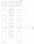
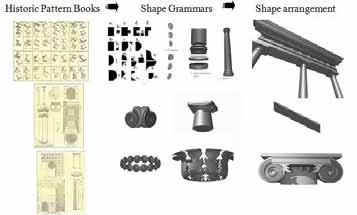
Using GDL the classical elements detailed in the pattern books are re -produced using a design framework based on parametric rules and shape rules. Objects are scripted with parameters making them dynamic objects that can be reused. A bottomup approach is adopted which starts with the smallest building objects such as ornamental mouldings and profiles. These uniform objects are created from a shape vocabulary of 2D shapes that allow for all configurations of the classical orders (Fig 1). Shape rules are used to transform these 2D shapes to represent classical mouldings and profiles. Non-uniform and organic shapes are developed in GDL through a series of procedures attempting to maximise parametric content of the objects (Fig. 1). These shapes are stored as individual parametric objects or combined to make larger objects such as columns, pediments, walls, windows or roofs.
parametric façade as a plug-in for the ArchiCAD BIM software.
Similar to the design of the library objects the parametric façade also uses architectural knowledge to assist with the digital reconstruction process. Architectural rules and proportions outlined in pattern books relating to classical building façades are used. The proportioning of a classical façade is determined by the geometry of the window openings, which is expressed in Fig 2 by the relationship between circles of the same radius. The top windows are made up of a single circle, in the next set of windows intersecting circles and finally in the lower set of windows the circles are placed one on top of each other. Using a para meter for the window width or circle diameter the height and position of windows can be calculated with these proportions. This provides an initial estimate for the position and size of window openings on classical facades. These proportions are evident in most classical buildings, however alterations to buildings can obscure or remove some of the origina l façade proportions. Alterations to a façade over time can include removal or enlarging of brick walls, window and door openings and parapets.
A parametric building façade has been developed as a template for fast and efficient modelling of endless configurations of building façades. The structure of a façade is procedurally generated by altering parameters for the number of storeys, number or horizontal tiles and door position. When automatically generating the façade, the initial position and size of elements are estimated using classical architectural proportions. After the façade is automatically generated users can then interactively edit the position, size and other parameters of façade elements to accurately map objects to survey data. Parametric library objects such as windows, ashlar block wall detail and other architectural elements are also incorporated into the parametric façade. This section describes the design and implementation stages for developing this
The design and conceptual framework for the parametric façade is based on concepts from shape grammars. A shape grammar is a production system used in procedural modelling to automatically generate two or three dimensional geometries from a basic vocabulary of shapes and a set o f production rules. A design and conceptual framework based on parametric design and shape grammars is described in this section.
The first stage of design involved evaluating a set of key parameters that would allow the façade template to be modified to model many different building façades. Efficient methods for editing these parameters also had to be established. The standard method for editing parameters of a parametric object is to specify or edit parameters from a list in a
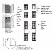
dialogue box. This approach is adopted for modifying global parameters or parameters affecting the entire façade. Editing more specific parameters relating to an individual object such as a window opening would be very time consuming and inefficient using this method as it would require a large number of parameters to be measured and entered into a dialogue box. To facilitate efficient parameter editing another method using graphical parameter editing has been designed. This method allows users to select a specific part of the façade in 2D or 3D and interactively edit the objects parameters by moving the object graphically. This enables parameters of the façade to be modified while overlaying the model with survey data in 3D or 2D. This removes the need for taking measurements and entering measurements into a dialogue box, instead parameters can be matched to survey data directly in 3D or 2D. Fig. 3 shows an example of the dialogue box for editing parameters from a list (left) and also graphical editing where a parameter for the distance between two floors is being altered in 3D (right).
wall. A second wall tile TD is used as a panel containing a door opening. Additional library objects relating to a door and door case such as columns and pediments are linked with this shape TD. Other shapes include library objects for windows and a simple block that is used to create detail for ashlar stone wall geometry. Additional library objects described in the previous sections are also used in conjunction with these basic shapes in Fig. 4.

Concepts from shape grammars have been adopted for the design and implementation of t he parametric façade. Shape grammars are a very suitable approach to architectural modelling as they allow models to be created from a vocabulary of basic shapes and set of replacement rules where a shape can be replaced or altered by transformations. These principles facilitate the encoding of classical architectural rules and proportions which also use grammars or vocabularies for architectural elements and rules to combine these basic shapes. The main concepts from shape grammars that are adopted for the parametric façade are the use of a basic shape vocabulary and production rules to transform the shape vocabularies to automatically generate façade geometry.
The basic elements that make up the vocabulary of shapes {S} can be seen in Fig. 4. Shapes include two wall tiles; one wall tile TW which contains a window opening and surrounding
A set of shape rules are used with the basic shapes shown in Fig. 4 to automatically generate various façade configurations. The shape rules {R} used are shown in Table 1. The concepts for many of these rules are based on the CGA shape grammar, [11]. Additional custom rules have also been developed for incorporating the architectural rules described in Section IVa. Table 1 shows the initial shape on the left hand side of each rule and the resulting shape on the right hand side after the rule has been applied. Each rule is applied with an assignment of real values to parameters for shapes and transformations if required such as translations, rotations, scaling or mirroring.
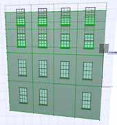
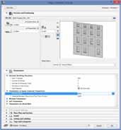
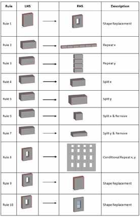
Rule 8 (Table 1) is the main rule that creates the façade structure. This rule repeats the wall tile TW in both x and y directions based on various parameter settings and architectural rules. This method contrasts to the concepts adopted in the CGA shape grammar [11] where a façade is split into smaller tiles. This rule repeats the input shape in the y direction for the first column, and then moves to the second column and so on until all tiles have been placed for the specified parameters. Parameters for the “number of floors” and “number of columns” control the number of repeated instances to be placed in each column and floor. The input for this rule is the shape TW and coordinates for this shape which is an assignment of the shapes parameters.
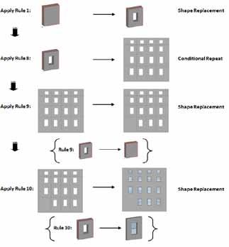
Fig. 5 shows the order and application of the rules shown in Table 1 to create the basic parametric façade. The application of rule 9 adds a door tile TD The position of this is obtained from a user defined parameter “windows to left of door”. The application of rule 10 adds window objects to all window openings on the façade. Global parameters for window objects can be entered and set from the objects dialogue box. Specific parameters for a particular instance of a window object can be set using graphical parameter editing.
for specifying parameter constraints and settings, a property script for writing component and desc riptor commands if the object is to be used in a schedule and finally an interface script to create custom dialogue boxes and input fields for modifying parameters. The main shape grammar vocabulary objects and production rules are coded in the 3D script. The 3D script is structured with subroutines and an executive script which is a controlling script used to call subroutines. Shape vocabulary objects are stored in individual subroutines and shape rules which are applied to shape vocabulary objects ar e coded in the executive script.
The vocabulary shapes used for wall tiles are coded using a GDL function cPRISM Other more complex shape vocabulary objects include a parametric sash window. This parametric sash window is the default window for the parametric façade. Future work will concentrate on developing more parametric window types where users will be able to select a window type from a library that will then be automatically added to the parametric façade. These window objects can be stored externally as separate macro objects and called from the parametric façade object. The default sash window created for the parametric façade has parameters to alter the window width, height, width and thickness of the window frame, sash frame and glazing bars, reveal depth and the number of vertical and horizontal glass panes in each sash.
The main rule that is used to generate the structure of a façade is rule 8 ( Table 1) which repeats the vocabulary shape TW in both x and y directions as outlined in section IVb. This is coded in GDL with a loop command to repeat the shape TW While repeating the shape TW using a loop command, IF statements are used to control the number of repeated instances in a particular column and also the number of columns to be placed. The user parameters for “Number of Floors” and “Number of Horizontal Tiles” are used to control this. Coordinate transformation are also used with this loop command to control where the next instance is to be placed. After the first instance is placed a coordinate transformation is used to move to the next position for the second instance. After all instances have been placed on a particular column then a coordinate transformation moves to the bottom of the next column for the next instance and so on until all instances have been placed for the specified parameter settings.
Coding with the Geometric Description Language (GDL) is carried out using different script for different parts of the parametric object being created
The 3D script is the main script for coding the 3D geometry. Other scripts include a 2D script for specifying a plan representation, a parameter script
Rule nine from Table 1 is used to place a door tile (TD) into the generated facade. The position of a door tile is obtained from the user defined parameter “Windo ws to left of Door”. Rule ten from Table 1 is used to add the vocabulary shape for a window object (W) to existing window tiles ( TW). The width and height of each repeated window object is automatically calculated from the size of the window openings in each window tile
Another rule is also used to add the vocabulary shape for a parametric ashlar block wall to the generated façade. The parameters for the width and height of the ashlar block wall are automatically matched to the parameters of the parametric façade. Users can choose to add ashlar block wall detail to all storeys of the generated façade or just the ground floor. When the ashlar block wall is being added to the façade Boolean operations are used to cut areas for window openings from the ashlar block wall. Fig. 6 shows an example of different façade models automatically generated with the parametric façade.
a)
Survey data obtained from laser scanning or photogrammetry can be used as source data for generating accurate façade models. Modelling directly to large point clouds obtained from laser or image data can be difficult as large point clouds can be very intensive on processing within BIM software which is not designed for such large datasets. T here can also be accuracy issues when modelling directly to point clouds in 3D space as it can be difficult to locate an object’s exact position within a dense 3D point cloud. Instead of modelling directly to a complete point cloud, segmented point clouds, orthographic images in elevation and plan and 2D cuts through a point cloud are used to generate asbuilt BIM models. All survey data, including georeferenced orthographic images can be imported into the BIM software using its source coordinate reference system to avoid any alignment errors between datasets
When the parametric façade is opened in the BIM software it is first positioned in plan relative to survey data such as orthographic imagery in plan created from a point cloud or mesh surface model The first stage of mapping the façade template to survey data is to apply the classical proportions to the façade model which provides an initial estimate for the position and size of façade elements

In order to apply these classical proportions two measurements need to be taken from the survey data and entered into the façade template as parameters. After these parameters are entered into the façade template the size and position of all elements on the façade model are immediately updated to reflect these classical proportions. When modelling classical historical buildings having these proportions already applied significantly reduces the amount of further editing to be carried out.
The next stage involves specifying the façade structure. This is be carried out by altering parameters for the structure of the façade either in a dialogue box or graphically in the 2D or 3D window by selecting and moving hotspots on the template. A user must specify the number of storeys for the façade, the number of horizontal tiles and the position of the door on the ground floor. By altering these parameters the façade structure is procedurally generated. Once the structure of the façade has been generated the façade model can be overlaid with survey data and the initial estimates for objects provided by applying classical proportions can be assessed.

The final stage involves graphically editing objects on the parametric façade model to accurately position elements relative to survey data. This is carried out in 2D or 3D while overlaying the model with survey data such as orthographic imagery. In order to enable efficient editing, editable hotspot points can move multiple objects at once. This simultaneous editing allo ws users to quickly alter the heights of all windows on a floor simultaneously, the width of all windows above each other in a column simultaneously and also the position of all windows in a column or floor simultaneously. The distance between floors and columns can also be modified graphically to move multiple objects at once. Along with this editing with groups of objects, individual editing of objects is also possible to achieve high levels of accuracy relative to the survey data. Individual window corners can be modified by simply selecting a hotspot at the window corner and moving it to the desired new position As an element on a façade is modified all linked elements are also automatically updated

Along with the methods for semi -automatically plotting building facades, manual plotting methods can also be used with existing individual HBIM library objects. The approach used with HBIM is to map the library objects in 2D onto segmented point clouds and orthographic images in elevation, plan and section. Before positioning a library object in the BIM software the default parameters of the object can be edited, changing the object’s shape, size or other properties to correspond with the survey data. When library objects are brought into BIM software they are first positioned in plan using orthographic imagery or cut sections through the point cloud. The height of the object is specified by a parameter for its formation level. Objects are then more precisely positioned in front and side elevation from further orthographic imagery and cut sections. Fig. 7 shows an example of a point cloud and subsequent BIM model created using the HBIM parametric library objects and parametric façade described in this paper.
design and implementation of the parametric façade object.
This parametric façade template facilitates fast and efficient modelling of endless configurations of building facades. A building façade structure is first procedurally generated by altering parameters for the number of storeys, number of horizontal ti les and the door position on the ground floor. When automatically generating the façade, the initial position and size of elements are estimated using classical architectural proportions. After the façade is automatically generated users can then interactively edit the position, size and other parameters of façade elements to accurately map objects to survey data. The parametric façade template has been implemented with the Geometric Description Language for ArchiCAD BIM software. This enables the tools developed to utilise the full benefits of BIM software which includes automated construction or conservation documents, semantic object orientated objects based on IFC semantic classes, automatic lists of objects and material and the ability to add and link additional information to the model.
Future work will involve extending the parametric façade with more parametric library objects such as further window types, various door types and door case detail from classical orders including columns, architrave detail, entablatures and pediments. Future work will also focus on a more procedural approach for generating entire building models and not just façade models. Finally future work will also investigate designing similar plug-ins for other BIM software such as Revit from Autodesk to enable the developed automated techniques to be used in many software platforms.
[1] Tang P., Huber D., Akinci B., Lipmand R. and Lytle A. (2010). Automatic reconstruction of as-built building information models from laser-scanned point clouds: A revie w of related techniques', automation in construction, vol. 19, no. 7, pp. 829-43.
[2] Hichri N., Stefani C., Luca L.D. and Veron P. (2013). Review of the as-built BIM approaches, paper presented to 5th international workshop, 3D-ARCH-2013. 3D virtual reconstruction and visualisation of complex architectures, Trento, Italy.
This article has presented a new approach for semiautomatic modelling of building facades from laser or image data using a parametric façade template which has been developed as a plug-in for the ArchiCAD BIM software. This methodology incorporates concepts from shape grammars for the
[3] Murphy M., Govern E.M. and Pavia, S. (2013). Historic Building Information Modelling –adding intelligence to laser and image based surveys of European classical architecture, ISPRS journal of photogrammetry and remote sensing, vol. ISSN 0924-2716.
[4] Boeykens S. (2011). Using 3D design software, BIM and game engines for architectural
historical reconstruction, paper presented to CAAD futures 2011, Liège, Belgium, 6 -8 July 2011.
[5] Boeykens S., Himpe C. and Martens B. (2012). A case study of using BIM in historical reconstruction - the Vinohrady synagogue in Prague, paper presented to the 30th international conference on education and research in computing aided architectural design in Europe, Prague, Czech Republic, 1214 September 2012.
[6] Fai S., Graham K., Duckworth T., Wood N. and Attar R. (2011). Building Information Modelling and heritage documentation, paper presented to XXIII CIPA inter national symposium, Prague, Czech Republic, 12th-16th September.
[7] Pauwels P., Verstraeten R., Meyer R.D. and Campenhout J.V. (2008). Architectural Information Modelling for virtual heritage application, digital heritage proceedings of the 14th international conference on virtual systems and multimedia, Archaeolingua.
[8] Chevrier C., Charbonneau N., Grussenmeyer P. and Perrin J.P. (2010). Parametric documenting of built heritage: 3d virtual reconstruction of architectural details, international journal of architectural computing, vol. 08, no. 02, pp. 131-45.
[9] Thaller W., Krispel U., Havemann S., Redi I., Redi A. and Fellner D.W. (2011). Developing parametric building models - the Gandis use case, paper presented to 4th international workshop 3D-ARCH 2011, "3d virtual reconstruction and visualisation of complex architectures", Trento, Italy, 2-4 March.
[10] Stiny G. and Gips J. (1972). Shape grammars and the generative specification of painting and sculpture, the best computer papers of 1971, pp. 125-35.
[11] Muller P., Wonka P., Haegler S., Ulmer A. and Gool, L.V. (2006). Procedural modeling of buildings, ACM transactions on graphics, vol. 25, pp. 614-23.
[12] Lipp M., Wonka P. and Wimmer M. (2008). Interactive visual editing of grammars for procedural architecture, ACM transactions on graphics, vol. 27, no. 3, p. 1.
[13] Müller P., Zeng G., Wonka P. and Gool L.V. (2007). Image-based procedural modeling of facades', ACM trans. graph., vol. 26, no. ACM, p. 85.
[14] Graphisoft (2011). GDL Reference Guide.
ArcDox
508 Q House, Furze Road, Sandyford, Dublin 18
E-mail: 1ralph@arcdox.com 2pat@arcdox.com
ABSTRACT - “Defrag the System”
We see the Construction & Property Sector as a highly fragmented “system” involved in the creation of information, that describes what a building is meant to be, how it is to be constructed, and how it is to be operated and maintained. In this fragmented setup, information about a building is contained in people’s heads, on their personal computing systems, in paper-based documents, in filing cabinets and boxes in storerooms. Building information is created, managed and exchanged through a complicated series of “transactions” between theses many stakeholders, using outdated paper-based devices. This information is difficult to access or process, and quickly becomes outdated or redundant. In this traditional setup, there is excessive duplication of information and effort, and the “collective intelligence” about a building, or the “building information model”, is a highly fragmented model, comprising the collections of people, the information in their minds, in their computers, in their paper documents.
In its purest and simplest form, the idea and promise of BIM, is that we can create a digital database to represent the building, that the various stakeholders can feed their contribution into, and draw required information out of, to carry out their particular task in a more efficient way, and that throughout the lifecycle of the building, there would be one source of true information about the single building, continuously developing and being refined over time. But for this to happen, we need to rethink the way we operate as an industry. We have to abandon paper-based “analogue devices” for communicating information, and start using new “digital devices”, we need to create information in a way that can easily contribute to a building database, we need to manage and track information flows to be sure the information database is trustworthy, and we need to control access to the information for those who need it, without compromising the security of the building, the project or the participants. We need to “defragment” the system.
Keywords BIM, Building, Information, Modelling, Database, Productivity
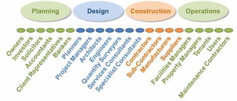
In the theme of cultural change required to leverage BIM (building information modelling) to transform the AEC sector, this paper aims to challenge industry to change the way it thinks about information about buildings (or building information), to reconsider how we create, manage and exchange information. It is the authors contention, that “transactions in information” are at the heart of all the processes of planning, designing, constructing, using and operating buildings, as all the various stakeholders involved in these processes require certain information in order to perform their task, and in doing so create further contribute information that will be needed by other stakeholders downstream. The speed of these “transactions”, and the quality and accessibility of this information, directly impacts, affects and determines the ability of each stakeholder to perform their task successfully.
The title of this paper draws on the analogy of computing devices reading information (data) off a storage device, in order to process that data, and write information back to the storage device, to save it for a later use. Fragmentation of the data stored on devices decreases the performance of the device. “Defragmentation” in computing technology, refers to the organizing of data packets on mass storage devices, into the smallest number of contiguous regions, to improve the read/write performance of electromechanical disk drives. This is the metaphor for the discussion of this paper, on how we can improve the performance of the AEC sector, through the effective and efficient creation, management, and exchange of building information.
The paper examine s some of the current forms of information production and exchanges in the industry to consider their shortcomings. We look at a number of “information transactions” between key stakeholders, to show how slight changes in methodology/process of these transactions, through
It is the contention of the authors that industry is extremely fragmented, and as a result, the “transactions in information” are very poor, leading to poor decision making, excessive duplication of effort, abortive work, introduction of human error, corruption and obsolescence of information about buildings (or building information), all contributing to the high waste factor, poor performance and high costs of planning, designing constructing, using and operating buildings. In this paper, we take a critical look at the “analogue devices” used for communicating building information (paper-based reports, drawings, schedules, specifications etc.) and suggest that there may possibly be a better way to handle information in this digital age in which we are living. We suggest that in order to bring about lean transformation of the AEC sector, we need to improve these “transactions in information”, and employ digital communication “devises” like BIM.
the application of technology, can bring about quantum improvements to the overall process. Applying ”lean” principles of “driving out was te” through each individual process, this paper will narrate the progress of a single building elements information (such as a door), from inception, through pre-planning, design, construction and postoccupancy operations and maintenance, and even to decommissioning, to explore ideas of how the use of BIM (or information technology) can improve interactions and transactions between the various stakeholders, to achieve better performance and better results in the AEC Sector.
This polemic paper seeks to broaden the outlook of the AEC sector stakeholders, beyond their own discipline and remit, to appreciate how their own process of gathering, processing and reporting (exchanging) information, not only impacts on their own business outcomes, but also on other
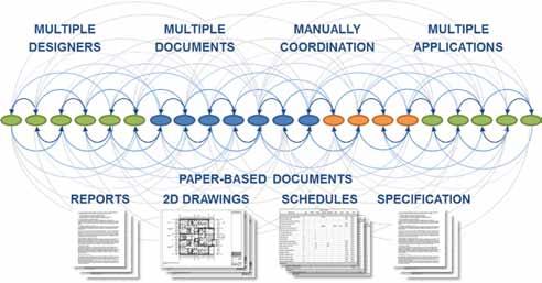
stakeholders and the overall success of a project throughout its lifecycle, to suggest that “defragmentation” of the industry to achieve a more integrated ways of working, focused on transactions of information, will bring about lean transformation. This paper will hopefully present some ideas to academic, research and working practitioners, to rethink current methodologies, to explore better ways of working.
We are all “consumers” of Building Information, as "...individuals, agencies, alliances, bureaus, businesses, companies, corporations, councils, courts, departments, guilds, institutes, organizations, societies and unions…” who are “…owners, occupiers, solicitors, bankers, accountants, project managers, planners, architects, engineers, surveyors, contractors, specialist designers, manufacturers, installers, suppliers, facility managers, maintenance contractors…”, required to carry out daily tasks to “…assess, insure, secure, scan, print, survey, test, appraise, entitle, broker, finance, lease, litigate, manage, maintain, manufacture, store, transport, hydrate, evacuate, fuel, electrify, design, permit, cost estimate, drill, excavate, pipe, construct and first respond…” (thanks to David "Joshua" Plager, AIA, CEO BIM Earth for the descriptions).
they need to make. The degree of “fragmentation” of the information, and the stakeholders involved, leads to excessive duplication of effort, abortive work, introduction of human error, corruption and obsolescence of information, which negatively affects the performance of projects. This paper aims to encourage AEC stakeholders to have better conversations, better interactions and transactions in information, to strive towards more integrated ways of working to improve performance and outcomes.

Consider how is information about buildings is currently created, managed, delivered, or presented for people to use. Is it easily accessible, relevant, and accurate? We live in a digital information age, and even though most people in the AEC sector use computers in some way to do their jobs, the primary means of communicating information about buildings today, between the various parties involved, is still through paper-based documents, reports, drawings, schedules (or lists of items), and specifications (or descriptions of items). These paper-based documents are all manually and individually produced by people. The process is slow, it is prone to human error, it is time-consuming
We all rely on timely and accurate ‘information’ to perform our task successfully. However, because of the high level of fragmentation of all the industry stakeholders, timely and accurate information, in an accessible and usable format, isn’t usually available, and more often than not, each party ends up recreating the information they require for themselves or for isolated transactions between a limited number of stakeholders. Even though all parties are engage in some way with a single building, there is no single pool of information from which parties can extract the particular piece of information they require, or into which each party can feed in particular contributions of information
and almost impossible to make sure that all the drawings, schedules and specifications all accurately describe the same building. Information quickly becomes superseded or out of date, as a design evolves or the building gets constructed and operated. It is too time and cost prohibitive to keep all the information accurate and up to date. There is an enormous amount of duplication of effort, as one party prints digital information onto paper, and passes it to another party, who then has to visually read and interpret the information and manually input this into their own digital system to carry out their element of work, before printing their results out on paper and handing it to the next party.
Besides being a very slow form of communication, with each visual interpretation and manual input, there is the opportunity to introduce human error. Missing information, misunderstanding of the information and coordination errors in the documentation, all lead to problems in the process of designing, constructing and operating buildings, introducing delays, abortive work, waste, additional costs, and ultimately disputes between the parties. And even once construction is complete, since different people have control of the various original digital source files that produced the paper-based documents; it is very difficult to manage the information during the buildings life, to keep it up to date.
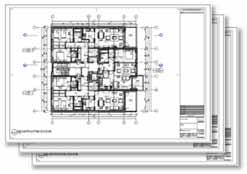
WHAT IS WRONG WITH A DRAWING?
Two dimensional orthographic projections of buildings and elements of buildings have been used for centuries to communicate information about what a building is, and how it is meant to be put together, so many people would argue that this is a proven tried and tested way of communicating information about buildings. But only if it is accurate, relevant to the task, and if the person looking at the drawing is correctly interpreting the meaning of the lines, arcs, circles and text, as intended by the person who originally produced the drawing.
the training and skill to produce or read drawings properly. The transfer and processing of building information, through drawings, happens in the human brain, and a lot of the meaning and understanding is lock in individuals minds, not fully accessible to everyone who may need to access that information at some stage, particularly after the individuals have moved on.
Also, let’s address the accuracy of drawings. Ea ch orthographic projection is manually drafted, and on a typical project there could be hundreds, if not thousands of drawings required to describe every aspect of a building. Different people, with different levels of understanding of the building, are involved in producing all the drawings. It is almost impossible to ensure that every individual drawing accurately describes the same building. Maybe in days gone by, when we had more time to produce and coordinate the drawings, the level of accuracy could b e higher, but as the world moves faster and faster, and we have to get tasks done quicker and cheaper, the accuracy level in drawings rapidly decreases. Some drawings are never updated to reflect changes that occur during design or construction, as it is to time and cost prohibitive to do so, but yet these documents remain in the final information set that transfers to the building owner.
Lastly, let’s address the relevancy of the drawing to the task at hand. The designers producing the drawings won’t always understand the particular requirements of each of the parties that might use that drawing downstream in the process. The designer may decide to draw a section through a staircase at a particular point, and not understand that the carpenter that will be building that stair actually needs a section to be drawn at another point, to make it relevant and useful to the task at hand, and so the carpenter either has to request a new drawing, or produce it himself.
So a drawing, as a means of communication of building information, requires a skilled person to produce an accurate and relevant document, but also a skilled person to read and interpret the document, and there is no way to measure or ensure that the message, or information, has transferred correctly. We only find out later, when something goes wrong, sometimes much later, when the person who created the drawings, and the person who interpreted the drawing, have long gone. Of the many people involved in the full process of planning, designing, constructing and operating buildings, very few have
People that interact with buildings are continually making up all sorts of lists or schedules of information that they need in order to make decisions and carry out their roles and duties. Whether these are lists of buildings on a campus, or rooms within a building, or tenants of those spaces, or the occupants their extension number, or the equipment or components in the building and their maintenance schedule. Most of these people are creating these lists for themselves, by visually reading information off other paper-based drawings and printed schedules from other parties, and recreating the particular information they require in a computer system of their own.
There are multiple valuable lists of digital data, or information about a building, scattered amongst the various stakeholders, but these lists are all disconnected, from each other, and from the reality of the building, as it has developed and changed during design, construction and operations. The information contained in these lists is invariably out of date and inaccurate. Since there is no agreed way to produce, structure and share information about a building, there is an enormous amount of duplication of effort, as one party prints digital information onto paper, and passes it to another party, who then has to visually read and interpret the information and manually input this into their own digital system to carry out their element of work, before printing that out on paper and handing it to the next party. Even if information schedules are shared in a digital format, the lack of agreed structure, coding and format, requires each party to manually restructure the data for use, and rather than linking their systems to a live database of current information, they are working on and with a copy of data taken at a particular point in time, so each party has to continually check and update their information lists against any updates taking place in the building. It’s slow, time-consuming and prone to human error.

The specification is a detailed technical description of every element of the building setting out its performance criteria, installation method and maintenance regime with reference to technical standards and building regulation codes. Buildings are made up of thousands of materials and elements, and very few people know how to write or compile a good project specific specification, or have enough knowledge to assemble all the relevant information required, or have the time to compile and manage this information during the design and construction stages, as decisions on building products and elements are continually developing and changing.
Project specific specifications could potentially be the most valuable and useful sources of information about a building, but more often than not, more generic “cover all situations” specification documents are used, and are never updated as decisions are being made during construction, and one wonders if these are ever used or referenced in practice. Also, the specification is a text based document developed separately from the drawings and schedules. In some instances designers set up a keynote cross-reference between annotations on drawings and the sections of the specification document, but this is a manual task of crossreferencing that has to be manually checked and updated. There is no quick and easy way to check that every element depicted on the drawings, or listed in the schedules, has a corresponding section in the specification document. Also, there is no quick and easy way of checking that every section of the specification document is relevant to the particular project. It’s all a slow and manual cross-referencing task that often gets overlooked in the fast-paced development of projects. The references in the specification document to performance criteria, technical standards and manufacturers recommendations for installation and maintena nce very quickly become outdated, as industry standards are continually changing during a project’s life from inception to completion and into operations.

To provide context to this discussion we can take an example describing the lifecycle of information about a single building element through the existing fragmented and disconnected workflows as we have experienced it on many construction projects, and while this example relates to a door it could equally relate to almost any element or component required for a building project.
Information about a door may start out as part of a Client’s brief “I saw this is a hotel somewhere” or maybe its requirements are at least in part defined by legislative requirements for fire, acoustics, access, or even by its particular use for security, radiation, etc. A lot of information about this door could be digitally captured and maintained, at this stage but typically this opportunity is passed by.
Once the concept is signed off the door will appear in several different guises as part of the scheme design documentation. At this stage the door may be described in plan, in elevation and in section, as separate redrawn representations of the same element.
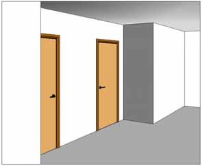
This door first appears graphically represented as part of the architects outline proposals describing the conceptual design in some initial sketches and maybe some 3D images.
The door may also appear in more developed computer generated images designed to impress the client. Again little of the information or data about this door is captured or recorded although many decisions about this door have already been made, at least in the minds of the designer and other stakeholders, as it is being drawn.
At detail design and production information stage the same door is again redrawn as 2D representations in several different disconnected documents including
• Plan drawings (2D cad)
• Elevation drawings (2D cad)
• Section drawings (2D cad)
• Room data sheets (2D cad)
• Detail drawings (2D cad)
• 3D Images (SketchUp / 3Ds max)
These may go through a number of iterations before the architect starts his developed design drawings. At this point the door has probably been redrawn several times and usually little of the known information about the door has been captured or recorded at this stage for future use.
• Legend / Schedules (2D cad / Excel) with little real or useful data recorded in any structured and easily accessible or retrievable database. Any change to the design at this stage requires all of the above documents to be changed individually with the real possibility of errors creeping in to different parts of the documentation.

At some point during the documentation stage the architect will research and review manufacturer’s information, make final decision on the door type, performance criteria, construction and finish in order to produce the project specification.
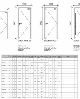
Again this is typically another disconnected document produced in specification software or simply in a word processing document (sometimes taken from a previous project and reused).
The architect may go back and revise the drawings and schedules at this stage, to reflect some change required based on this detailed research, but typically this does not happen.

All of the above documents, which are required by the current system or process to describe the door, are issued to the quantity surveyor for take -off and production of the Bills of Quantities. The QS includes a description of the door in the bill of quantities (which becomes the pricing document), and hopefully this reflects the architects requirements as described in the specification, schedules and drawings, which hopefully reflects the clients requirements, and legislative requirements –a lot of cross checking is required.

The Main Contractors (probably at least 4 -6 different companies) will recount and recheck the information about the door, extract and repurpose the BoQ’s, drawings and schedules relating to the door in order to send enquiries to suppliers to get them to te nder for the manufacture, supply and installation of the door.
Up to this point the QS typically has had very little input or influence on any the decision about the selection and specification of the door. It’s quite possible that the door does not fit into the budget for the project which could well require the drawings, schedules and specifications to be revisited to suit the budget or a difficult conversation needs to be had with the client.
The Bills of Quantities is added to the coordinated (hopefully) drawings, schedules and specifications and issued to the contractor for tender. This would usually be in the form of paper copies or PDF files with little ability to interrogate or search for data where it exists within the documents. The contractor will have to visually inspect all these documents to find the information.
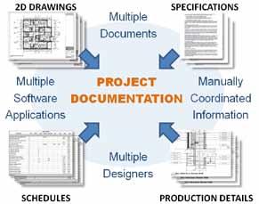
The Suppliers (probably at least 3 -4 different companies) will again recount and recheck the information about the door and produce their own schedule in the format they require for pricing. This is submitted to the main contractor who again has to check the information. The tender is submitted back to the design team as a paper-based (or PDF) document that requires a visual inspection to make sure the contractor has allowed for the door in his tender.
When the tenders are received, a value engineering exercise may be required to get the overall project cost within budget, and changes to the design or specification of the door may be required to be incorporated in all the documentation.

Assuming the project goes ahead and the supplier and main contractor are appointed, a submittal will be prepared and sent to the architect for approval. This will generally require the supplier/contractor to produce their own drawing, schedules, specifications, test certificates and data sheets describing the actual door to be provided.
The installed door will have to be checked and signed off.
• Door snagged by installer and recorded
• Door snagged by contractor and recorded
• Door snagged by architect and recorded

All the information about this door (its type, manufacturer, performance, certificates, installation date, maintenance requirements etc.) which are required for the O&M manuals & Safety File will then need to be gathered checked and assembled into a lever arch file, possibly with a pdf copy on d isk, and placed in a box in a storeroom for retrieval by the building operations and maintenance team.

These documents are again disconnected from the design intent documents with more opportunity for errors or omission to creep in. Once the door supplier’s details have been agreed the architect will (maybe?) update their documentation to reflect the actual door type and any other implications on the design required to incorporate this actual door.
The Supplier will need to break their schedule down to suit their manufacture and delivery process. Drawings and information may need to be produced to finally allow the door to go to manufacture, or formatted for automated CNC machines. Once manufactured the door will be QC checke d and recorded in the factory. The Door will then be delivered to site and again QC checked and recorded by the main contractor – documentation, tracking delivery.
Hopefully in line with the programme, the door will be installed in the correct location and recorded. This can often be the first time the client sees the door (and realize this isn’t anything like the door they “saw in a hotel somewhere” but probably forced to accept it anyway as it is too late or too costly to change).
Because the information in the lever arch files is not in an easily accessible digital format, or late in coming, or missing altogether, a FM company will generally spend months re-creating FM information relating to the building and its assets in their own systems, including the best information they can derive about the door from a visual inspection. At some point over the life of the door, ironmongery will be replaced with some alternative, because the original information in the lever arch file has gone missing and no one can remember the specification. Maintenance of hinges and closers may be
ed or not carried out at the recommenced intervals because the building manager is not aware of the manufacturer’s maintenance recommendations set out in the product information cut sheet. The door may get damaged and replaced with a different door, perhaps not meeting the original performance specification, and more than likely this change will not be recorded or updated in the missing lever arch file.
At some point the building may be sold or let to a different tenant at which point the original lever arch file, if discovered, is handed over to the new owner/tenant purporting to be an accurate record of as built.
As we see from the example above, information about building elements are being reproduced multiple times during a project lifecycle. Described above is a complicated series of “information transactions” using poor paper-based devices, with excessive duplication of effort, abortive work, introduction of human error, corruption and obsolescence of information, which is all contributing to the overall cost of the project without adding real value. The process is slow, cumbersome, problematic, and results in delays, variations, cost overruns, excessive administration and disputes. You have to ask “is there a better way”?
communicate all the detail and complexity of a building in a single 3D model, and a hybrid approach is still being used, with a combination of 3D model derived drawings with overlaid annotation or added 2D elements and drawings. Also, the communication or exchange of information between different proprietary software formats results in corruption or loss of information. A lot of the potential benefits of communications are being lost, because parties are not sharing their 3D model information in a useable format, and resort back to industry practices of printing information on paper for information exchanges. Despite the limitations, significant improvements in productivity, accuracy and communications have been gained through this virtual building approach.
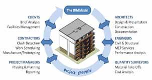
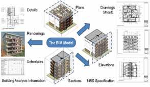
The concept of developing a virtual 3D building in software, to address some of the issues associated with 2D drawings started over 30 years ago. The premise was that classic orthographic projections required for drawings could be automatically derived from a single 3-dimentional model of a building, to ensure all the drawings would be accurate and coordinated (describe the same building). It also meant that the design could be reviewed and communicated in 3D, a format more understandable to the broader group of people or stakeholders involved in a project, where design and coordination issues could be more easily seen, and anybody could easily and quickly take any view of the model relevant to their task, and not have to depend on the limited set of drawings provided by the designers. This idea has matured over the last 30 years, but it still isn’t perfect. It is still not possible to
In more recent years the focus in shifted from the value of the 3D Model, to also investigate the value in the metadata or information that can be stored and communicated through the objects that make up the model. More advanced 3D object-based modelling software packages, allow metadata about the building elements to be attached to the objects that make up the model, making them “intelligent”. Rather than just being a collection of 3D geometric forms, faces and extrusions, objects can represent their real-life counterparts, and be categorized, automatically listed and counted (scheduled), hosting, displaying and communicating important metadata about the building element. Potentially the 3D BIM can become an information rich database that can be used to gather and manage all the information about a building in a single environment, so that information only has to be created in one place, and if a change is required, it only has to be updated in one place, significantly simplifying and improving the process of building information management. And potentially this valuable information database can be can be easily and digitally exchanged or accessed by other parties downstream. A powerful idea, but this still isn’t perfected. For the first part, there is no industry agreed structure of what data is required and how it should be formatted, and so each software vendor that has been exploring this idea has been doing so within their own concept of how this should work. Consequently, this valuable data is often tied up in a
proprietary file format, which is of limited use to other parties outside a particular discipline, involved in other processes or using different software. That said, with growing industry interest in leveraging the building data, there are moves to develop harmonised data structures and translations between formats. The other issue is access to the data. The typical approach to date has been to develop and maintain the data within software file format rather than a true external database, limiting the potential for various people to interface with the data over networks, as one would expect from a true database.
Sometimes it helps to step outside of one industry into another, to make comparisons. One of the simplest examples of a useful functioning accessible database is booking airline flights. If you want to book a flight from Dublin to London on a particular day, you can go to a website, put in some key information (point of departure, destination, date), and the computer will search a database of airline flight schedules and price lists of a number of travel agents that meet your specific criteria in minutes, and present you with options, and if you choose, you can contribute to that data pool by adding your information (make a purchase, book a seat, change the availability for others searching for flights after you). The information being accessed is always “live” – it’s not a copy taken by someone a few days ago. Information that previously had to be captured by travel agents off paper booking forms, like your name, address, telephone number, passport number etc., can be put directly into the database, and eve n maintained over time, by the end user, and yet access is controlled, so the end user cannot inadvertently change the schedule of the flight, or tamper with other peoples information. The same information can easily be passed to the airlines, airport security etc., eliminating endless duplication of effort and form filling and streamlining the experience for everyone involved. It is still not perfect, but it has completely changed the way people travel and book flights and the “transactions in information” have been vastly improved.
A few important things had to happen in order for these improved “transactions in information” to take place and it’s worth considering these as we seek to “defragment” our processes in the AEC sector.
Firstly, there has to be a “willingness by each party to participate” – to be willing to share and provide access to a subset of their information to others, in a live, useful accessible format, but also provide the ability for 3rd parties to contribute to their database. So the airlines need to provide online travel agents with live flight schedule information, but also allow the travel agents to submit the passenger’s details. The benefits to the airline in providing the infrastructure, is that they d on’t have to manually input and manage the passengers details. Equally, the travel agents need to be willing to share this flight schedule information and their price schedule with prospective passengers in a live, useful accessible format, and provide the ability for 3rd parties to make selections and contribute to their personal details to the database. The benefit to the travel agent is that their customers can be searching and purchasing flights at any time from their own computers, without requiring an agent to perform the searches, and capture personal details. The benefit to the passenger is that they have far more flexibility to search for suitable flights and comparisons in prices. Everybody benefits in some way by being willing to participate.
The second important thing to make a useful accessible multiparty data environment is that there must be an agreed format and structure to the data. Every airline must use the same airport code and date/time format when making their flight schedule information available, so that travel agents can make direct comparisons and queries, automatically handled by computer systems, and not require human intervention to reformat/structure data for different airlines. That’s why the potential passengers are provided with drop-down lists for airport names and calendar dates on the travel websites, so that they are using the same codes and date/time formats, in order to query the data automatically. Equally, the travel agents need to provide the price information in the currency relevant to the user making the query, and when the customer enters their personal details, it has to be captured in an agreed format that can populate the databases of the travel agent and airlines automatically, with requiring a human on the other end to re-input the information. The name, surname, address, telephone, passport number fields must be consistent across the industry, to easily exchange information between databases.
Lastly, in order to make the system work properly in real time, parties have to provide access to the live database, not a copy, since the data is changing all the time (availability of seats decreasing as bookings are made). If an airline is providing 3rd parties access to their live database, they have to have control on what information can be viewed, and what information can be changed. The airline wants the travel agents to be able to see the flight schedule information and availability, and add the passenger information, but not to inadvertently change flight schedule information, or mine protected data of other passengers. The passenger wants to be sure that when they input their personal details and credit card information, it is secure and won’t be distributed or misused. There has to be a full audit trial of how information has been created/provided, should the need arise to go back and investigate.
A last important point is that in order to work, the interface must be user -friendly, otherwise people won’t adopt it. Presenting a potential passenger with a complicated database system, which they need to purchase and train to use, in order to go and set up a data query to book their next holiday, wouldn’t work to encourage participation. Online booking systems are simple easy to use, freely available web applications that only requires the user to input 3 bits of information (departure, destination, date) to get the query started, and then only gathers further information as required, validating informat ion at each stage as part of the process. Obviously there are complex infrastructures and complicated database management systems behind the scenes that drive this process, but not everybody needs to know how these work.
Imagine an Online Building Information Management System that was as easy to use as an Online Flight Booking system. Imagine if the receptionist on the third floor of a building could open a simple webpage to report that the light bulb in meeting room No.3 has gone, and that would automatically update the facilities management database, generate a works order, check the stock, and if necessary, even place an order with the supplier for a replacement part, and schedule which maintenance person needs to replace the bulb.
Imagine if the client in our “door example” above, could open a web page, and record his requirements for the door, with a picture of the door he saw in the hotel, into the building information database, and that information was available to all relevant stakeholders for the duration of the project, as they
simply added additional information to the same database over time.
Level 3 BIM described in the Bew/Richards BIM Maturity Model, used by the UK Government BIM Task group, aims to begin thinking about information about a building being described as an integrated digital database, where parties will feed information into the database, and other parties can draw information out of the same database, vastly improving the creation, management and exchange of information. Current fragmentation of the people involved in buildings, and the information they produce, is having a negative i mpact on processes and outcomes for construction.
In the computer hardware world, fragmentation makes your hard disk do extra work and slows down your computer processes. Defragmentation rearranges data on your hard disk to make accessing and using the data work more efficiently. In the construction industry, existing processes with fragmented data results in everyone involved doing extra hard work which slows down the processes, and ultimately costs the industry millions in wasted time and effort. Defragmenting the data for a construction project, to make accessing and using the data work more efficient , could result in savings in time and effort for everyone. A central data base for projects linking all the data required through an easily accessible 3D BIM model interface, a single ‘source of truth’ about the building from initial concept through to operations and maintenance and even final decommissioning has enormous potential benefits for everyone, and should be pursued and investigated with great interest by all.
Dublin, Ireland
E-mail: aok@rod.ie
Abstract Bridge engineering involves many discrete stages throughout the life cycle of a bridge, within both the delivery phase of the infrastructure project and the subsequent operation and maintenance of the asset. Each stage comprises multiple complex processes by large project teams and relies on the efficien t exchange of information throughout. Bridge information modelling is a form of 3 -dimensional product modelling and involves many of the same processes used in building information modelling. It presents the opportunity for improvements in information flow throughout a bridge life cycle. Significant developments have been seen in the area of bridge information modelling over the last decade. By identifying a number of case studies, this paper reviews how bridge information modelling is being used on current international bridge projects from conceptual design, through preliminary and detailed design, to construction, operation, assessment and maintenance. A literature review is performed on recent relevant academic studies in the areas of bridge engineering, site surveying, building information modelling, and information exchange.
Keywords Bridge, information, modelling, civil, engineering, interoperability.
The life cycle of a bridge, from design and construction through to operation and maintenance, requires repeated exchange of information about the structure. Optimising this information exchange enables more productive working by all project participants, reduces the risk of error, and allows more time for design iteration and value engineering. Traditionally the exchange of information has been through 2D drawings, with some exchange via computer aided design files, text files and other formats specific to software vendors. The increasing prevalence of building information modelling (BIM) over the last 10 years has led to improved flow of information between project participants on building schemes. BIM is a form of 3D product modelling that enables information to be read by humans and machines.
This paper reviews how the principles of BIM are applied to bridges, commonly referred to as bridge information modelling (BrIM). The latest developments in the use of BrIM from design stage through to operation and maintenance are discussed. Standard data exchange formats are assessed and their adoption in leading countries is assessed.
Key decisions are made about the form, location and make-up of bridges during conceptual design. Significant savings can be made in the initial capital cost and the ongoing operational costs of a structure through appropriate decision making at early project stages. Engineers typically carry out options studies , assessing various designs on the basis of technical aspects, economics, aesthetics, environmental impact, health and safety, maintenance requirements and buildability. Utilising BrIM at conceptual design stage allows designers to assess multiple options more quickly and more thoroughly.
Some of the large software vendors have design suites which can parametrically link standard conceptual bridge designs to road alignments. As road designers update their model, bridge models can be modified accordingly. Au tomated quantity take-off can be linked to databases of material costs to produce cost estimates which accurately reflect the changing data in the model. Digital terrain models, geotechnical models and geospatial models of utilities can all be used to improve the information available to designers at this early stage
and minimise major design changes at later stages in projects, when they are more costly to implement.
Similar techniques are used widely in the building design industry by those who have moved to BIM based design. As the tools available for conceptual bridge design become more prevalent, it is anticipated that clients will expect BrIM processes to be used for their bridge structures. However, the Author is not aware of any suitable conceptual design case study at this time.
Significant benefits to designers are available through the use of BrIM at preliminary and detailed design stage. Where a model is correctly compiled, objects are parametrically linked For example, reinforcement will change in geometry and location when a column is increased in diameter. Drawings and schedules are dynamically linked to the model, thus ensuring consistency of information, swift implementation of design changes, and accurate quantity take-off.
The bi-directional link between BIM authoring tools and structural analysis software packages has enabled building designers to reduce data entry, limit the potential for human error, and carry out value engineering more easily. This link is particularly suited to structures which are comprised of columns, beams, walls or slabs such that members can be idealised as line or plate finite elements. In this scenario, the location, material, geometry and boundary conditions of the element are easily defined. Some bridge forms, for example trussed structures, fall into this category and the bidirectional links can be used during design. However, the idealisation of many bridges for global analysis requires particular approaches to be taken, such as grillage, line beam or 3D frame analysis. The approaches simplify the structural model to enable reduced computation time and ease of results interpretation. For example, for the global analysis of a cable-stayed bridge designers generally idealise the pylon and deck as a series of line elements, with their stiffness calculated from the cross-sectional properties of the members Stiff elements can be used to model transverse eccentricity, such as the distance from the deck centroid to a cable anchorage. Figure 1 below provides example from the proposed Narrow Water Bridge between County Louth, Ireland and County Down, Northern Ireland.
Current bi-directional links between proprietary software package s do not facilitate this idealisation, although designers can develop a
bespoke software system that facilitates data exchange for each structure.
When used correctly, solid finite element analysis (FEA), using tetrahedral or hexahedral elements, provides greater accuracy than the line and plate models discussed above. Bridge designers often develop solid finite element models of complex connections, applying load effects taken from the global model. FEA software allows for import of solid geometry models through proprietary exchange formats such as DXF (although this does not cater for the exchange of other useful information such as material properties or the construction sequence) However, it is not common for designers to create a solid finite element model of a complete structure.
Romberg et al [1] report how the classical finite element method (h-version) requires that finite elements have an aspect ratio of close to unity in order to prevent shear locking. On structures with thin members, this requirement leads to having an analysis model with a very large number of degrees of freedom, as the size of the elements is dictated by the smallest dimension For long structures such as bridges, which often have thin walled structural components, the above requirement would lead to an analysis model which has such a long computational time as to make it impractical for iterative design use.
Romberg et al. propose the export of solid geometry models from IFC product models of structures (see Section 5d below), and the subsequent import into analysis models. They propose the use of p-version finite elements for thin walled structures. These elements permit the use of aspect ratios of a few hundred, thus enabling a significant reduction in the number of degrees of freedom and the computational time for thin walled
structures. Were this to be adopted for bridge design, it may be practical for global solid FEA models to be used more frequently The element formulation also allows for nonlinear computations, an important consideration in bridge analysis. However, the Author is not aware of a recent bridge project where this approach to data exchange has been adopted.
Although BrIM is becoming more popular, current procurement methods still require the inclusion of drawings in contract documents, while the complex geometry of many bridges leads to the need to produce a significant number of drawings to portray the design intent. In addition, the method of working for site teams is still based around the printed drawing.
Sacks and Barak [2] researched the effects of BIM on the productivity of drawing production in a structural engineering design practice. The findings showed a conservative potential productivity gain of between 15% and 41%. The two projects used in the research were multi-story buildings, where repeated floor layouts would have assisted with the improvements in production. Similar benefits are available to bridge designers where a structure ’s deck, pier or pylon cross-sections are repeated or are subject to repetitive geometric rules with some varying dimensions.
The Crusell Bridge is a cable-stayed structure in Helsinki, Finland. Construction was completed in 2011. The bridge has asymmetrical spans of 92m and 52m. The use of BrIM on the project is widely reported as it was one of the first such structures to be built using the process. The designers of the Crusell Bridge used parametric BrIM to develop the drawings for the pylon and abutments [ 3]. Productivity improvements were reported but, given that it was the designer’s first large project using BrIM and the bridge was complex in nature, many lessons were learnt for use in future projects.
Following a 3D analysis, and possibly having developed a 3D computer aided design (CAD) model, bridge designers traditionally have provided 2D drawings to the contractor. This leads to a significant loss in data for those involved in construction. However, when BrIM is used during the design phase, it is possible for contractors to adopt the model, develop it further, and use it for various aspects of the construction stage.
The optimum approach often depends on the method of procurement, whether it be design -bidbuild or design-and-build. It should be noted that there are contractual, legal, risk management and insurance issues related to which ever procurement
approach is adopted, although discussion of these issues is outside the scope of this paper.
Some aspects of how BrIM can be used by contractors and their supply chain are discussed below and case studies are provided.
The facility to link 3D model data to a construction schedule (i.e. 4D modelling) provides multiple benefits to contractors. Accurate measurement of materials required for each construction activity can improve the use of space on site. The movement and interaction of work teams can be optimised to prevent having too many trades in one area at any one time. The movement of plant, machinery and temporary works around a site can be assessed more readily. Risks to the health and safety of workers can be mitigated through the use of 4D models for visualising work sites and assessing hazards.
Shim et al [4] developed a BrIM model of the World Cup Bridge project in Seoul, South Korea. The requirements of a hypothetical contractor were taken into account in the model through the inclusion of basic work breakdown and product breakdown structures. This led to a model which included scheduling data (4D) and construction management information (5D). In addition, a methodology for using the 4D model to assess, quantify and manage construction and safety risks was proposed. The outcome of the research was that BrIM is “judged to have significant application value in reducing risks and for construction management” [ibid.].
The value of the clash detection tools in BIM software is well documented, particularly for building design and construction. Buildings contain components specified by multiple designers including architects and civil, structural and building services engineers, thus leading to a high potential for clashes. In most cases, the permanent works of bridges are designed by one organisation. However, the risk of clashing components is introduced through the size and complex geometry of structural members, the density of reinforcement or structural steelwork in zones of high load transfer, and the inclusion of services ducts. In addition, bridge construction requires significant temporary works , thus leading to further risk of clashes. Accordingly, clash detection using BrIM tools presents a potential benefit to bridge designers and contractors.
Eastman et al [3] explain how the contractor’s site team on the Crussel Bridge project added all the temporary works to the per manent works model thus enabling the identification of multiple clashes which
may not have been noticed until those particular works were progressing on site. The complexity of the permanent works is shown in Figure 2
Association of Finnish Civil Engineers awarded the structure the “Bridge of the Year 2013”, with particular reference made to the groundbreaking use of BrIM by the design and construction team. Figure 3 shows the finished bridge at night.
Steel fabricators have been using BIM since before the term was popularised. Various hardware and software systems have been used to develop accurate fabrication models of steel structures. The systems output shop drawings and computer numeric control (CNC) information to automated machinery. The drawings are dynamically linked to the model thus minimising rework when design changes occur. However, these models generally have been developed from 2D design drawings.
Eastman et al describe how the design and fabrication models were integrated on the Crusell Bridge project. The steel design model was provided to the fabricators, who edited the model to suit their fabrication constraints, and in turn submitted the model to the designers for approval. As well as improving the flow of information from the designer to the fabricator, it prevented the need for the designer to review the fabricator’s shop drawings and compare them to the design drawings. The design and fabrication models also contained schedule data and this was used to optimise the delivery and erection of components on site.
All of the reinforcement in the Crusell Bridge was modelled in 3D within the BrIM model. This was used to carry out clash detection within the reinforcement and with ducts, steelwork and cable anchorages. However, Eastman et al. discuss how the information flow between the designers and the reinforcement fabricator was not as fluid as that with the steel fabricator. Data was provided in ASCII format which could be automatically read into the fabrication software, but this data did not include the schedule. As such, manual processes needed to be used to ensure the correct bars were delivered to si te during each construction phase.
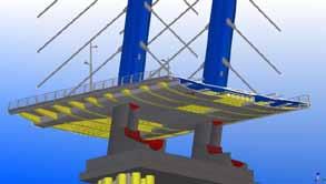
The Crusell Bridge project has been recognised for its commitment to the use of BrIM. The

Kivimäki and Heikkilä [5] present how BrIM models can be used to assist with setting out of bridges on site. Complications are introduced to setting out due to the need to accommodate the deformed shape of a structure such that the final shape provides the correct alignment for the bridge deck Setting out points can be selected in a model and exported to a total station for use on site. Asbuilt measurements can then be taken and imported back into the model to facilitate the development of an as-built model. However, modelling carried out at earlier stages needs to include parametric linkage of objects. Otherwise the task of creating an as-built model would be particularly onerous.
The operation and maintenance of bridge stock leads to significant annual expendit ure by bridge owners. BrIM is being used on various projects to optimise the value available to those owners. There are two primary aspects to the use of BrIM for bridge asset management.
Firstly, where a new bridge is designed and constructed using a complete BrIM process an asbuilt information model of the structure is available to the bridge owner. The model can be used by bridge inspectors to familiarise themselves with the structure, while inspection reports can be appended to the model, along with the pre-existing information from construction stage. Structural assessments based on reported deterioration can be carried out more easily by availing of the structural analysis information embedded within the model. The model can be used for designing, procuring, scheduling and recording maintenance operations. However, due to
the relatively recent advent of BrIM, the Author is not aware of any cases where these processes have been applied.
The second aspect of BrIM for bridge asset management is the development of models for rehabilitation and retrofitting of existing stock where no previous model is available. This approach is becoming more frequent as the advantages of BrIM are better understood Two case studies are described below
A recent case is from the Seismic Safety Project for the San Francisco-Oakland Bay Bridge (SFOBB). At the eastern end of the bridge, a 100m section of double-level truss was replaced with a new truss over a three-day period in 2011 [6] Due to the very tight programme for the works, the client, California Department of Transportation (Caltrans), and the design team decided to utilise BrIM to optimise the sequence for the roll-out/roll-in replacement. The model was used to minimise geometric conflicts, carry out structural analysis, and develop steelwork fabrication drawings. Construction risks which could have delayed the works were mitigated through the use of the model. Figure 4 shows an overhead view of the construction simulation between the time when the old span was rolled out and the new span rolled in. Note the inclusion of all permanent and temporary works.
Multnomah County, Oregon, USA require the online replacement of Sellwood Bridge, a 335m long fourspan steel truss over a river. The new bridge is due to open in 2015. However, [7] and [8] discuss how a temporary replacement bridge is required to maintain traffic flow while the new bridge is being built. The contractor proposed to lift the existing bridge and translate it 13m offline during a six-day road closure.
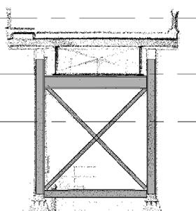
The existing truss and its surroundings were laser scanned and the point cloud was imported into BIM scheduling software. Figure 6 shows a section through the point cloud and model. Figure 7 shows the bridge model and point cloud at the abutment, including existing structures near the bridge approach
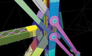
Abbas et al. [6] also described how BrIM models were developed by Caltrans to investigate the potential retrofitting of eyebar chains in the 425m cantilever. Figure 5 shows details of a joint at an eyebar chain.
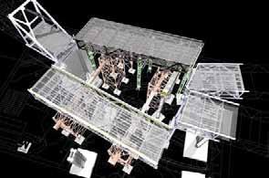
Various construction methodologies were assessed, taking into account the proximity of the adjacent buildings at one end of the bridge. The point cloud was used to develop a BrIM model in order to design the bridge translation and programme the works, with the comfort that accurate measurements of the site were available. The operation was completed in January 2013 , taking one day less than expected.
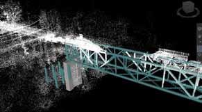
the IFC format. IfcXML is a programming language that facilitates the exchange of data through IFC and is also developed by BuildingSMART.
IFC-Bridge was released in 2007 as an extension to the IFC model. It was theoretically validated by a group of French experts and was developed “to capture design information for providing a standard exchange and archiving model data related to the whole bridge life cycle” [9]
The adoption of BrIM by all participants in the management of a bridge life-cycle relies on effective data exchange. Many software tools are available which contribute to different aspects of the design, construction and operations phases. An important consideration is the ability of users to adopt the software which best suits their needs while being satisfied that data exchange is robust. This section looks at some standard data exchange models that are available for bridges. It is noted that, in line with the principles of Lean, greater adoption of BrIM will likely be seen when exchange between software packages is thoroughly tested and trusted by designers.
STEP (ISO 10303) is used by the manufacturing industry for the exchange of product data between project members. Industry foundation classes (IFC) are based on STEP but are focused on data exchange in the architecture, engineering and construction (AEC) sector. They are developed by BuildingSMART which is a consortium of international software vendors and public sector bodies involved in the AEC industry and with an interest in standardising data exchange. However, it is an open standard, registered with ISO as ISO 16739.
The latest release is IFC 2x4 (IFC4), which was published in March 2013. Software vendors of BIM tools allow for import and export of models through
However, Yang et al [10] discuss how the model does not facilitate the exchange of parametric design information between parametric software applications. The ultimate value from BrIM can only come when parametric models can be exchanged readily between project partners, with the geometry of the bridge deck based on parameters set for the road alignment and topography. Yang et al. proposed an “object-oriented data structure extending IFCBridge which supports parametric geometry representations”. This allows the exchange of parametric models between the bridge design and structural analysis software systems, which was tested as part of the research. Ji et al. [11] extended the research to include the exchange of parametric model data between two design software systems.
The CIS/2 (CIMsteel Integration Standard) data model for exchange of structural steel information was developed by the Steel Construction Institute (UK). It can be used for describing parts (straight, curved, tapered, bent, decking), assemblies, analysis loads and reactions, materials, layouts of bolts and holes, weld paths, camber and drawing references. Information can be exchanged between project team members for analysis, design, detailing and fabrication of steel elements. It was adopted by the American Institute of Stee l Construction in 1998. Many BIM software packages facilitate the import and export of CIS/2 files.
A number of public clients in various countries have implemented BIM mandates in recent years, including some in the USA, Finland, Norway and Singapore. Others are planning for widespread adoption of BIM within the next few years. This section reviews developments in two counties which are leading the use of BrIM.
Finland has been at the forefront of developments in BIM (and its predecessors) in recent decades. Since 2007, the agency responsible for managing the State’s property assets, Senate Properties, has
required IFC models to be submitted at various key stages of building projects [12] Finnish academic institutions, public authorities and private companies work closely together in researching and initiating new technological processes for design and construction.
As discussed by Heikkilä [13], various projects have been carried out since 2001 to develop improved processes for bridge design and construction. One project, Bridge Finland, led to the publication by the Finnish Transport Agency of National Guidelines for Bridge Information Modelling and Automation in 2011. The Guidelines cover various aspects of BrIM, including: model level of detail at various project phases; technical guidelines on coordinate systems and identification of objects; integration of models and drawings; quality control; utilisation of the model at the construction stage; and lega l aspects of information exchange between parties.
Subsequent projects were due to commence in 2011. The researchers planned to continue development of the Guidelines based on reported experience from the initial implementation.
A parallel project is Infra FINBIM, which is being led by RYM Ltd, a company funded jointly by private industry and public bodies. The main aim of the project is to introduce to the construction industry the outcomes of recent BIM research and to encourage major infrastructure owners to procure projects through BIM from 2014 [ 14].
Following a series of reports commissioned by the UK government over the last 20 years, the Government has decided to mandate the use of BIM on all publicly funded projects by 2016. This is part of a wider strategy to reduce the cost of capital projects by 20%. The supply chain will be required to submit information (referred to as data-drops) regarding a project at key stages The data model to be used is CoBIE (Construction Operations Building Information Exchange) CoBIE is not a geometrical representation of a building but a sub -set of model data which can be used for operation and maintenance. The file format can be viewed as a standard spreadsheet and most of the large BIM software vendors are developing the ability for their products to export CoBIE files.
The UK BIM mandate will apply to all capital projects, including road and bridge projects [ 15]. CoBIE was developed for use with buildings and it is not clear to the Author how the data model will be used for bridge projects and, accordingly, how bridge designers will comply with the mandate. However, the UK BIM Task Group is working closely with bodies such as the Highways Agency to
assist with the implementation of BIM and it is expected that the application of BIM to road and bridge projects in the UK will have a profound effect on the construction industry [ibid.].
The UK construction industry (and other countries mandating BIM) has recognised the need to standardise BIM based collaboration and related contractual agreements. PAS 1192-2 [16] was published in February 2013 and specifies the information management for the delivery phase of a projects using BIM. Various other related standards are either available or in development. The Construction Industry Council published the CIC BIM Protocol [17] for use as a supplementary legal agreement between employers (owners or contractors) and professional services providers. Other protocols have been developed within the UK and internationally. The use of standards and protocols, such as those described above, during the delivery and operation stages of bridge infrastructure will be an important factor in the successful implementation of BrIM processes.
This paper presents the state of the art of bridge information modelling and its use from early design stages through to operation and maintenance. It is evident that BrIM is providing exciting opportunities for clients and their supply chain to design and build better structures faster and for less cost.
The IFC-Bridge and CIS/2 data models can be used to exchange information about bridges but widespread adoption is not evident. Finland and the UK are leading developments in the use of BrIM and the mandating of BIM respectively.
While there is a significant way to go before data can be seamlessly exchanged throughout the life of a bridge structure, the rapid pace of recent change is exciting and presents many opportunities and challenges to the bridge community.
[1] R. Romberg et al , “Structural Analysis based on the Product Model Standard IFC”, in: Proc. of the 10th Int. Conf. on Computing in Civil and Building Eng., Weimar, Germany, 2004.
[2] R. Sacks and R. Barak, “Impact o f threedimensional modelling of buildings on productivity in structural engineering practice”, Automation in Construction , vol. 17, issue 4, pp 439-449, May 2008.
[3] C. Eastman et al., “BIM Case Studies”, in BIM Handbook – A Guide to Building Information Modelling for Owners, Managers, Designers, Engineers and Contractors. 2nd ed. Hoboken,
New Jersey: Wiley, 2011, ch. 9, sec. 5, pp. 494
513.
[4] C. S. Shim, “Three-Dimensional Information Model-Based Bridge Engineering in Korea”, Structural Eng. Int., vol. 22, no. 1, pp. 8-13, Feb. 2012.
[5] T. Kivimäki and R Heikkilä, “Bridge Information Modelling (BrIM) and Model Utilisation at Worksites in Finland”, in: Proc. of the 27th Int. Symp. on Automation and Robotics in Construction , Bratislava, Slovakia, 2010, pp. 505-513.
[6] A. H. Abbas et al. (Accessed: 2013, June 25). San Francisco-Oakland Bay Bridge benefits from bridge information modeling [Online].
Available:
http://www.gostructural.com/magazine -articlegostructural.com-6-2011san_francisco_oakland_bay_bridge_benefits_fr om_bridge_information_modeling-8351.html
[7] E. Cylwik and K. Dwyer. (Accessed: 2013, June 25). Virtual design and construction process is changing how contractors build highways and bridges [Online]. Available: http://www.cenews.com/index.html
[8] Multnomah County. (Accessed: 2013, June 25). Sellwood Bridge Project [Online]. Available: http://www.sellwoodbridge.org/
[9] BuildingSMART, “IFC-BRIDGE V2 Data Model, Edition fonctionnalité R7 BuildingSMART, France, 2007.
[10] Y. Ji et al , “Integration of Parametric Geometry into IFC-Bridge”, in: Proc. of the 23rd Forum Bauinformatik, Cork, Ireland, 2011.
[11] Y. Ji et al , “Exchange of Parametric Bridge Models using a Neutral Data Format”, J. of Computing in Civil Eng., doi: 10.1061/(ASCE)CP.1943-5487.0000286, Dec. 2012.
[12] Senate Properties. (Accessed: 2013, June 24). BIM Requirements 2007 [Online]. Available: http://www.senaatti.fi/document.asp?siteID=2 &docID=517
[13] R Heikkilä, “National Guidelines for Bridge Information Modelling and Automation”, Gerontechnology, vol. 11, no. 2, doi:10.4017/gt.2012.11.02.342.00 , Jun. 2012.
[14] InfraBIM. (Accessed: 2013, June 24). Information Modelling to Renew the Infrastructure Sector [Online]. Available: http://www.infrabim.fi/infrabim_uusi/index.ht ml
[15] BIM Task Group. (Accessed: 2013, June 27). BIM Task Group [Online]. Available: http://www.bimtaskgroup.org/
[16] Specification for information management for the capital/delivery phase of construction projects using building information modelling , PAS 1192-2, British Standards Institution, 2013.
[17] Building Information Model (BIM) Protocol , CIC/BIM Pro, Construction Industry Council, 2013
1Department of Engineering and Built Environment, Dublin Institute of Technology, Dublin, Ireland
2Department of Engineering and Built Environment, Trinity College Dublin, Dublin, Ireland
3School of Real Estate and Management
Dublin Institute of Technology, Dublin, Ireland
E-mail: 1alan.redmond@mydit.ie 2rwest@ltcd.ie 3alan.hore@dit.ie
Abstract The engineering environment has recognized that much of the waste that is generated throughout the lifecycle of a building to the result of people not having access to information that others have created but is not accessible when created. Concerns about productivity by owners and industry groups have emphasized that the high level of waste is a direct result from a lack of interoperability and that the industry generally perceives lack of interoperabilit y as an impediment to improving productivity. This paper reviews the author’s thesis rationale which was influenced through the recognized difficulty of exchanging data at element or object level which depends on the information requiring compatible hardware and software, in order for the data to be read and transferred freely between applications. The solution was not to introduce a new schema in contrast to the industry’s existing open exchange model ‘Industry Foundation Classes’ which has been in existence since the 1980’s (most recent standard - 2 x 4), but for the author to reengineer an existing Simplified Markup Language ‘BIM XML’ into subsets via XML Style Sheet Transition. The language of XML was chosen because, Web services; which are developed from XML data representation format and Hypertext Transfer Protocol (HTTP) communication protocol, are platform neutral, widely accepted and utili zed and come with a wide range of useful technologies and they support Service Oriented Architecture (SOA – internet platform that enables interoperability between different software programs).
The methodology involved developing a full hybrid research model based on mixed methods, ‘quantitative and qualitative’, interlaced into two main phases. The first phase comprised of a main survey questionnaire, focus groups, two Delphi questionnaires, semi-structured interviews and a case study.
The final phase, ‘product design and testing’ used semantic methods and tools, such as, Business Process Management Notation. The final case study (prototype test) successfully itemized the potential of combining three applications asynchronously in real-time. The interoperable capabilities of Web services APIs for exchanging partial sets of BIM data enabled assumptions with a higher amount of detail to be reviewed at the feasibility design stage. Future service will be build upon existing Web Ontology languages such as (SPARQL) descriptions to be used in conjunction with several web services connecting together on a Cloud platform to produce know ledge ‘Semantic Web’.
Keywords Cloud BIM, BPMN, Subset XML, Collaboration, Information Exchanges, System Engineering
This paper is based on the authors submitted PhD document which designed and tested a prototype for exchanging partial sets of Building Information Modeling (BIM) on a cloud -based service. This integrated process would advance key decisions at an early design stage through faster information exchanges and improve best practices during collaborative work that are readily transferred to project teams using Cloud-BIM software. The
thesis rationale was influenced through the recognized difficulty of exchanging data at element or object level which depends on the information requiring compatible hardware and software, in order for the data to be read and transferred freely between applications [1] and [2]
The concept of interoperability allows seamless data exchange, at the software level, among diverse applications with their own internal data structures. The process involves mapping parts of each participating application’s internal data
structure to a universal data model and vice versa. The concept is to employ a universal open data structure enabling other applications to become interoperable via mapping and eliminate the costly practice of manually integrating particular applications [3].
In the construction industry, Building Information Modeling is the most integrated shared model between all disciplines. It is based on a manufacturing-like process where standardized deliverables are used throughout the life cycle with effective collaboration as its main driving force. The properties of BIM are; parametric modeling –providing tabular views of components and characteristic interaction with elements. For example, if a pitch roof changes so does the walls, and bi-directional co -ordination – enabling virtual simulations of physical construction. However, the dilemma is how to share these properties of BIM applications on one single platform. Thus creating a service that would enable the end-user to use multiple of nDs such as, 3D (three dimensional modeling), 4D (time – programming), 5D (costing) and 6D (sustainability) actions asynchronously Cloud Computing is a centralized heterogeneous network that enables different applications to be connected to each other. The prospect of using remote data servers with Web service applications provides a mechanism for exchanging data openly. The main exchange format for BIM files are Industry Foundation Classes (IFCs). However, IFC retains the EXPRESS schema, which create documents that are more intricate and voluminous in comparison to an information model optimized for XML. For instance; 800 entities ( data objects such as ifcMaterial), 358 property sets; container class that holds properties within a property tree (property sets are assigned to objects ( IfcObject) through an objectified relationshipIfcRelDefinedByProperties), and 121 data types (ifcActor such as clients linking with ifcElements) these numbers reflect the complex yet schematic richness of building information models [4].
The proposed model was not to introduce a new schema in contrast to IFC but for the author to re-engineer Simplified Markup Language subsets of XML, in order to exchange partial data sets of intelligent object architecture on an integrated platform that would enhance the BIM usability experience for various disciplines in making key decisions at a relatively early design stage. The concept of using both Cloud computing and BIM originated from the facts that Cloud computing possess four key attributes
1) static features – the interface and commands are roughly the same regardless of where and when the applications are used,
to allow one application to interact with another, 4) inter applications communications – the ability of an application to use the service features of another [5] and [6] reiterated these findings insisting that BIMs cost benefit analysis, to that of structured information that is organised, defined and exchangeable (with these key characteristics computer programming object architecture can be exchanged more successfully) will enhance productivity. The use of a Cloud BIM would enable faster information exchanges between various disciplines at the feasibility design stage of a project
The standard of IFC was approved by ISO/PAS 16739 referring to a computer system with a data base. Its concept was to feature data about how a building is presented for example; surface colors, line weight and line colors. This standard also specified how the data would be represented in data files, in order for software vendors to develop interfaces, which would read and write files. The initial IFC file format originated from the International Standards Organization (ISO) 10303 Part 21 file.
The challenges of using IFC are associated with having building models available for corresponding model servers to store all kinds of data being extracted from the exchanging mechanism. This relates to the specifics of how each individual software tools do not perform the exact same transformations [7]. In recent issues, the XML specifications defined by Document Type Definitions (DTD) in Part 28 (ifcXML) are not an open-ended data model like XML Schema (XSD), which extends custom markup languages and establishes complex relationships between elements without validating documents [8].
However, as attractive as this Hub or Cloud BIM strategy appears, a heavy reliance exists on an IFC object model that creates speed and accuracy difficulties, such as exchanging pertinent data. Conventional thinking requires processing a complete project data model, so innovators began searching for alternatives, such as simplifying the full model into subsets or through the novel use of XML. Frequently trade associations test innovations with Testbeds before recommending new practices to their paying members. The Architect, Engineering, Construction, Owner Operator, Phase 1 (AECOO -1) Testbed
3) modular interactivity - the ability
2) standards for data interchange – options for saving data or for importing data are standardized,
commenced in 2008 with the objective to crea te standards that would allow software (such as energy analysis and quantity take-off) providers to streamline communications and information exchanges between project participants during the design phase of capital projects. The process involved creating an Information Delivery Manual (IDM), which articulates what building information is required and a Model View Definition (MVD), which is the smallest set of IFCs that are needed to, express the information requirements of a particular IDM [9] Major technological industries have emphasized that a relatively smaller subset of IFC data is sufficient to enable business procedures to take place [10].
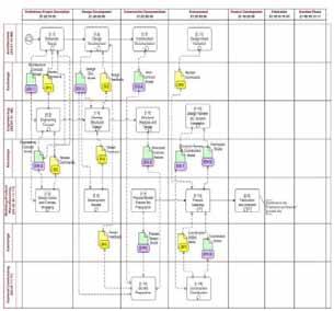
It has been identified that the challenges facing large engineering industries relates to orchestrating the work of numerous organizations and professionals towards a common goal. The Inteligrid a world-leading EU FP6 grid project in the AEC context has harnessed grid technology and semantic (where the infrastructure manages the meaning of the data) interoperability through virtual organizations. The use IDM was implemented as a key technology to make structured information exchanges work on semantic collaboration among business [11].
Until 2008, there were two separate development teams concentrating on IDM and MVD. Originally IDM developers mapped functional specifications directly to the IFC schema whereas MVD developers began their process by developing a generic MVD. However, in late 2007 a primarily agreement was established to integrate both teams. This meant that IDM would focus on the end -user requirements definition and MVD on the translation of those requirements into exchange representations and implemented into software products. There are different areas of the building industry that have different information needs (i.e. an architect’s needs are different than an engineer’s) and in order to examine the needs of various professionals the NBIMS project committee workgroup documented exchanges through use Cases based on BPMN [12].
Figure 1 is an example of a process map for structural precast the overall structure is referred to as “swim lanes”. The components of the swim lanes are divided into horizontal lanes identifying actors such as activities of the progression through the lifecycle of a business process and vertical defining the stage stages of the process.
The value of IDMs in capturing data exchange requirements has been recognized within the context of developing an energy-efficient BIM
framework. In order to identify the IFC capabilities each functional part needed to be supported in terms of their entities (data objects), attributes (element of information), and property sets (container class) and properties (objects) required
The concepts of IDMs were orchestrated into four main parts: i) process maps - describe the flow activities for a particular business process, ii) exchange requirement - characterising a set of information that needs to be exchanged, iii) functional part – unit of information used by solution providers to support exchange requirement, and iv) business rules – these are the constraints that may be applied to a set of data used within a particular process. It was this structure assisted the designed methodology for a life cycle energy management, adaption and extension of IDM [13].
The scope of ISO 12006 part 3 which relates to defining concepts by means of properties, to group concepts in order to define relationship between concepts was recognized as the basic entities of taxonomy (classification) model for BIM. “The model described in this standard is proposed to bridge between classification systems as described in ISO 12006-2 and product modeling”. However, it is recognized that no explicit definitions had been included into the standard to regulate the use of taxonomies modeled with this meta -model.
In order, to maximize the concepts defined in libraries Beetz and de Vries proposed the design of four hierarchical meta -modelling layers (abbreviated as M#). The product descriptions were based on IFD namely; (1) The kernel layer
M0
consisting of a straightforward translation of EXPRESS schema into using Ontology Web Language (OWL - ontologies capture key concepts and their relationships in a machine interpretable form), (2) the concept library layer M1 – concepts and entities such as local taxonomies and classification system i.e. OmniClass, Uniformat and MasterFormat are gathered, (iii) the product kernel layer M2 – this layer acts as an instantiation (an abstraction) of M1 such as “door panel” defined as a concrete product “Door model 4711 by Manufacturer X” and, (iv) product instantiation layer M3 – developing concepts provided by a central repository on the product library layer. With regards to partial modeling the added value attributes of Resource Description Framework (RDF - based upon the idea of making statements about Web resources such as expressing the relationship between a subject and an object) and OWL have several advantages in comparison to using STEP. With regards to Representational State Transfer (RESTful - Web service API) query endpoints in existing RDF query languages such as SPARQL (used to express queries across diverse data sources, stored natively as RDF or viewed as RDF via middleware) and SeRQL (Semsame RDF Query language, combines the best features of other languages and adds some of their own) can be used for much more efficient retrievals of complex graphs than currently with SOAP API in the ifd-library.org reference implementation and reducing the amount of calls and answers in order to retrieve for example; “all properties and measures and values of the door concept” [14].
The overall method incorporated grounded theory, where the result of each survey is examined to develop new theoretical propositions and the process involved triangulation of dataobservation from many angles (surveys) [15].
The methodology involved developing a full hybrid research model based on mixed methods, ‘quantitative and qualitative’, interlaced into two main phases. The initial phase was derived from a series of survey techniques; a main survey questionnaire (philosophical orientation), focus groups, two Delphi questionnaires (formalizing domain knowledge), semi -structured interviews and a case study. The case study involved a research technique, ‘Function Analysis System Technique’ (FAST), used for displaying functions in a logical sequence to prioritise them and test their dependencies (applying strategic framework to case study). The final phase, ‘product design and testing’ used semantic methods and tools, such as, Business Process Model’s Notation (BPMN).
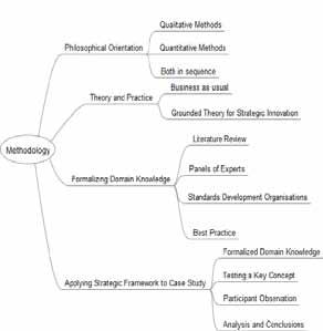
The overall order of sequence was established in the five key areas of BPR namely; (i) developing a business vision, (business strategy, drivers and barriers, business model – added value and market requirements), (ii) identifying a process to be designed, (iii) understanding and measuring an existing process, (iv) identifying IT levers, and (v) design and build a prototype of the new process [16].
The first initial phases of the methodology feature an extensive literature review investigating the challenges of interoperability for BIM software in relation to data exchange formats and how cloud computing may revolutioni ze the construction industry by exchanging information between different applications through openly co llaborating on an internet platform. The literature review stage identified the questions for the main survey. The mains survey targeted 90 respondents representing a mixture of non-random (40 international vendors) and probability sampling (50 Irish construction firms). The main themes of the research survey included investigating drivers, barriers and benefits of ‘Cloud Computing.’
The results of the main survey contributed to the discussion topics undertaken in the Focus Group sessions. The Focus Group comprised of 10 vendors in the Irish construction-marketplace. The group analysed various issues such as, security concerns relating to data being stored outside of Europe and the potential of developing a hybrid cloud (mixture of both public and private) for the group.
The ‘Delphi technique’ which followed,
comprised of two consecutive survey questionnaires. The initial questionnaire concentrated on information extracted from the main survey and focus group. The questionnaire’s ultimate aim was to analyse the potential for developing a cloud service based on combining three individual applications; originally identified as; BIM, project management and accountancy. The subsequent questionnaire compiled the results of the initial questionnaire and formatted new questions based on these results. This questionnaire’s main objective was to investigate how to develop a BIM service prototype.
The methodology was based on a heuristic approach (longitudinal study) and had been constantly evolving depending on the results of each stage. The structured interviews, in parallel with measuring an existing process, were the final stages of the initial phase of research relating to the first three key areas of BPR.
The purpose of the semi -structured interviews was to map a business process and identify the mechanics of developing a product. The case study involved a virtual project to be tested, which comprised analysing ‘BIM XML,’ an SML using import and export plug-ins which exchange data between different applications on a cloud platform in real-time. By undertaking this test, it highlighted the capabilities of BIM XML and identified how this process could be integrated with the concept of exchanging data simultaneously between three independent applications on a cloud platform using Web services similar to Geography Markup Language (GML).
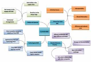
The aim of the final stage was to initially test the Information and Communication Technology (ICT) capabilities of the prototype ‘Cloud BIM’ using a robust XML Schema Definition (XSD) feature of BIM XML. The analysis involved testing the service from an end-user’s perspective, in order to establish if the main aim of the research ‘to develop an integrated process that would advance key decisions at an earlier stage through faster information exchanges that can readily be transferred to project teams using Cloud -BIM software’ than had been achieved.
In mapping the business process characteristics for using Cloud BIM (see Figure 3, which illustrates the mapping of the responses to the four key areas associated with the CLOUD BIM vehicle; driver
for Cloud BIM, standard business practice, technology shift and design and operate), the main drivers highlighted where efficiency was gained namely through reducing costs, shared information through interoperability and unlimited access. The need for a standard exchange prompted responses, such as; it is only necessary when integrating with other companies as there are so many types of information, a basic standard would be adequate. However, the question of whether the industry is ready for such an adoption identified the need to have both technology push and business pull, in order to ensure success. In analyzing if BIM is most suited to the ‘design and operating’ procurement route, the respondents indicated that it is but also acknowledged that it can be used for every procurement route. The major incentive for using design and operate was the fact that the same organization is responsible for the design, construction and operation leading to significant efficiencies. In practice, relating to the design stage, the design team would input most of the information until the contractor became a part of the design team, thus adding buildability knowledge before outsourcing to their supply chain (subcontractors) who would also contribute.
In response to the identification of the major contractual barriers for implementing BIM Cloud based software, current contracts and the lack of clarity over ownership, was identified as a major barrier. One respondent stated that the current contracts do not cover information exchange and that the issue of ownership does not surface until the project is completed when the client requests the model for their system. In reply the designer may state that they have the copyright for the models and as the contract does not require delivery of intellectual property, the model will reside with him/her.
Erik Brynjolfsson, director of the MIT Center for Digital Business, coined the term ‘organizational capital’ based on the theory that companies in the 1990s were not just investing in ICT but also in new business processes. These investments were rewarded with gains in 200 12002 but when ICT spending dropped, so did the investments in organizational capital, which created the downward slope for 2006 (during which, the software productivity output declined).
Brynjolfsson insisted that in order to achieve returns in three to five years, organizational capital must be a part of a company’s structure. The theory of organizational capital requires both business managers and computer programmers to collaborate in developing applications; whereby business managers outline their work tasks through a business process flow diagram and computer programmers develop software to suit [19].
In May 2004, the Business Process Management Initiative (BPMI) drafted the Business Process Management Notation 1.0 specification. The primary objective was to eradicate the productivity bottleneck in writing software code. By using a simple set of flow chart symbols, business managers could describe a process in a flowchart (as a Business Process Diagram - BPD), and software developers could implement these workflows into an executable
code. This procedure would enable managers to monitor largely automated practices through reports or electronic dashboards. The main purpose of undertaking a BPD is to create a standardized structure between the business process design and its implementation. A BPD should be based on a Universal Modeling Language (UML) standa rd. The outline procedure refers to a business process model, as a network of graphical objects, such as, activities and flow controls that are defined in a sequence of performances.
Ideally a process management should support a set of object attributes t hat have been mapped to the Business Process Execution Language for Web services (BPEL4WS v1.1 - specifies actions within business processes with Web services Processes involve exporting and importing information by using Web service interfaces – see Figure 4) the process execution standard [20] and [21]
With reference to the case study and testing the re-engineering performance of BIM XML, the author created individual BIM process maps to define when Web services should be imported and exported using BIM applications. Each of the task flows were fully analyzed and represented visually. The five main tasks were, cost estimation, cloud 3D co-ordination, developing a virtual model, creating a 4D model and performing an energy analysis. These were the chosen exchange flows related to designing a process flow notation for the feasibility design stage. The use of WFS (connect individual Web services together) and cloud network (modular interactivity and inter applications communications) provided a strategy for managing and improving business performance through optimizing business processes coupled
with the technological solutions of subset XML.
The system architecture designed for Cloud BIM services provides a usability vision of how the BPMN process would work. The core issue of cloud computing, being a big data system (data that exceeds the processing capacity of conventional database systems), coupled with BIM, shows how to provide a system that can enable various disciplines to work collaboratively. The component architecture of Figure 5 refers to the overall system, as a manageable subsystem which enables open access for all construction design disciplines. The system was designed by the author consisting of the following:
Basic layer: the systems basic layer for FUSION+ONUMA (Fusion – facility management software and Onuma – cloud computing BIM infrastructure) contains backend and basic data services and logics. Data services are services that read or write data from or to one backend system. Basic services adaptors provide a common service API, so that the backend/database can be accessed through Service Oriented Architecture (SOA).
Process layer: the concept of the BIM catalogue services and registries (managing services from a technical point of view) hosting the user-defined services, BIM services, data exchange services and product services was based on BIM interoperability through a service interfaces approach. The usage of the registries and repositories is to simply search the services maintained on the registry. Usually a Universal Description, Discovery and Integration ( UDDI) directory service is used to lo ok up XML schemas and other standard Web service interfaces.
Enterprise layer: this layer provides the end users with the required information to perform their tasks. The GUIs will enable multiple users to connect to the cloud platform through their Web browsers. The ability to achieve this connection relates to the architecture of the previous layers referred to as a Web application server.
The overall objective of the case study was to show the key benefits of Cloud BIM through its capability of exchanging partial sets of BIM data between applications, such as; improved communication and collaboration among project participants, enhanced project decision making, more accurate planning and scheduling, greater process standardization, cross-discipline coordination / virtual issue resolution and an understanding of the construction environment through visualization from the beginning.
The sequences of events in chronological order were as follows:
Briefing – there were no available drawings of Building 4200 but there was a reconnaissance sketch outlining the sizes and layout of the rooms.
Knowledge database – the FUSION database was used as a repository for all facility data about the campus, the opening interface of Onuma System provided access to both FUSION and GIS asynchronously.
Composed services: the composition of services allows one to provide support for business processes. The purpose of this central processing layer was to use BPEL to specify the exporting and importing of information through Web service architecture between companies. By ac hieving this objective the business flow diagrams would highlight the benefits of either creating IFCs or plug-ins based on XML schemas; particularly SML, in reference to being uploaded to a Web repository (manage services and their artifacts from a business point of view).
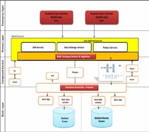
Design spatial occupancy – FUSION information was converted from a basic square with all its associated data (with reference to level of model detail ‘basic design’ – building footprint, building use, floors and occupancy); and designed to meet the existing layout plan (level of model detail ‘medium’ – rooms, partitions, open space and access).
BIM Software – this was the first stage that did not use WFS (contrast with using SOAP, the WFS used in the case study are based on RESTa collection of network architecture principles that focus on simple access to resources) the building file was exported using p lug-ins and imported into Revit and Vasari (Energy analysis
software using Revit code) at this stage the design was formatted taking into consideration the results of the energy analysis such as using 36% fenestration ratio to the buildings floor area.
IFCs were used to import data into such applications as Autodesk and Synchro in order, to create programs (4D), costings (5D) and simulations.
Palisade risk assessment was the only application that represented proprietary software exchange of data.
Energle – FM: a Web-based wireless sensor connected to the Onuma System interface via Web service APIs, the application monitors as-is conditions, such as, energy usage based on temperature, humidity, CO2, and Lux Level.
The results reflected the benefits of transferring nD information through subclasses of BIM XML and plug-in exchanges. The interoperable capabilities of Web services APIs for exchanging partial sets of BIM data enabled assumptions with a higher amount of detail to be reviewed at the feasibility design stage. With regards to planning, the BPEL work flows defined the sequence of performances for exchanging information, establising a protocol for accessing data and developing a strategy for the feasibility study.
a) Performance metrics of the case study and its finding
Improved communication and collaboration among project participants: traditional methodthe traditional techniques of using stand -alone or proprietary data exchange mechanisms have been consistent. Projects to date have achieved their required performance indicators. However, the industry recognises that the supply chain is fragmented, as entry barriers for SMEs exist due to the lack of technical ability (not having the required software). Cloud BIM featuring subset of XML for exchanging data - as the author was the project’s only participant, this benefit is hypothetically measured. Certainly the aspect of using WFS to instantly share and use facility data without leaving the BIM server model allows for open and instant collaboration via Internet.
Enhanced project decision making : traditional method - ethernets already exist but these collaborative hubs require the building design to be undertaken through stand -alone applications before being uploaded to the hub ; Cloud BIM featuring subset of XML for exchanging data - the ability to analyze information at the earliest stage through the Internet enabled assumptions with a higher amount of detail to be reviewed earlier, such as, deciding on the spatial and design content based on data derived from FUSION.
More accurate planning and scheduling : traditional method - The actual main software for developing the work and schedule program with a simulation movie was based on a stand -alone application that used the open exchange schema of IFCs to transfer information. Cloud BIM featuring subset of XML for exchanging data - the ability to
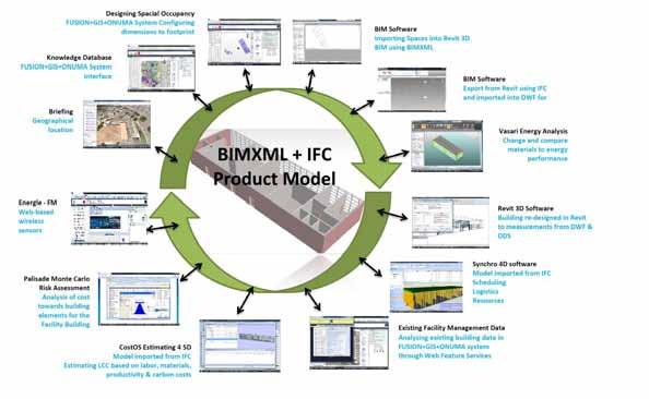
have instant data allowed the author to have more time when considering certain scenarios. The BPEL work flows had already advanced the planning and scheduling of the project and the level of model detail required for exchanging data.
Greater process standardisation : traditional method - The majority of the stand-alone applications used in the case study was to IFC 4x2 standardization, which does indeed streamline the exchanging of documents (noted not as fast as Cloud BIM). Cloud BIM featuring subset of XML for exchanging data - both BIM and cloud computing characteristics are based on standards for data interchange – options for saving data or for importing data that is standardised.
Cross-discipline co-ordination / virtual issue resolution: traditional method - Co-ordination between cross disciplines through the traditional technique happens at a slower pace than Cloud BIM. However, some disciplines prefer to only share information when they are ready, as opposed to the instant alternative. Cloud BIM featuring subset of XML for exchanging data - with access to the project in virtual real-time through the internet, the potential exists for stakeholders and design disciplines to co-ordinate on an open platform at any stage of the project.
Understanding of the construction environment through visualisation : traditional method - 3D and 4D BIM is used regularly in the Built Environment but not in collaboration at the feasibility stage and certainly not asynchronously. Cloud BIM featuring subset of XML for exchanging data - the FUSION+GIS+ONUMA Systems use of three services, facility management, geospatial data and BIM collaborating simultaneously enabled the feasibility and design briefing stage to be visually analysed [23].
Within the spectrum of sustainable building and infrastructure the technology designed by the author can be presented on two immediate platforms.
• Frame work for multi-disciplinary collaboration models: use the developed subset XML schemas of BIM XML to exchange facility management - geospatial and design data at the feasibility stage of construction development
• XML to become the universal technology for representing data passed between Web apps: demonstrate that Web service architecture is
advancing the develop ment of a computeroriented web.
In order for these two predictions to be fully implemented in a functional occupancy within the engineering environment, traditional development of vertical applications need to shift to Web service architecture allowing horizontal and virtualized connections (decoupling of the middleware) to other operating systems. Semantic Web is about knowledge and representing knowledge in the form of conceptualization (truths, beliefs, perspectives, judgments, methodologies, and know-how) and by defining relationships we are creating a Web-based knowledge that can define sets of objects, and the relationships among them. The method for creating knowledge on the Web relates to developing agents that have autonomous and rational behavior to interact with each other ‘Multi-Agent System (MAS).’ For example; Web Ontology language (OWL_S such as SPARQL) descriptions are directly grounded on WDSL interface definitions, and assume that services are invoke with SOAP messages. This technique can be used in conjunction with MAS service to provide agents with additional knowledge about the services with which they are interacting (Artificial Intelligence). The creation of the Case Study System architecture was a process of several web services connecting together on a Cloud platform to produce knowledge ‘Semantic Web’.
The authors would like to say thank you to Mr. Deke Smith (buildingSmart Alliance), Prof. Bob Smith (California State University) and a specially thank you to Mr. Kimon Onuma (Onuma Systems) and the BIMStorm crew.
[1] M Alshawi and B Ingirige, “Web-enabled project management: an emerging paradigm in construction”, Automation in Construction 12, Elsevier Science B.V., 348 – 364, 2003 http://www.elsevier.com/locate/autcon
[2] M Alshawi, ‘Rethinking in Construction and Engineering, Organisational Readiness ,’ Talyor and Francis, Oxon OX14 4RN, UK, 2007.
[3] National Building Information Modeling Standard, Transforming the Building Supply Chain through Open and Interoperable Information Exchanges; Version 1 - Part 1: Overview, Principles, and Methodologies , 2007 National Institute of Building Sciences, http://www.wbdg.org/pdfs/NBIMSv1_p1.pdf
[4] EF Begley, ME Palmer, and KA Reed,
'Semantic Mapping Between IAI ifcXML and FIATECH AEX Models for Centrifug al Pumps,' Building Environment Division Building and Fire Research Laboratory, National Institute of Standards, U.S. Department of Commerce, and Technology Administration Technology, 2005.
[5] BA Sosinsky, Cloud Computing Bible, Published by Wiley Publishing, Inc. 10475 Crosspoint Boulevard, Indianapolis, IN 46256, USA, 2011.
[6] DK Smith and M Tardiff, ‘Building information Modeling, A Strategic implementation Guide for Architects, Engineers, Constructors, and Real Estate Asset Managers,’ Wiley and Sons, Inc., Hoboken, New Jersey, USA, 2009.
[7] KA Jorgensen, J Skauge, P Christiansson, K Svidt, KB Sorensen, and J Mitchell, Use of IFC Model Servers Modelling Collaboration Possibilities in Practice, Aalborg University, Final version May 2008.
[8] M Morrison, Sams Teach Yourself XML in 24 Hours, Third-Edition, SAMS, 800 East 96th Street, Indianapolis, Indiana, 46240 USA, 2006.
[9] L Jr Hecht and R Singh, “Summary of the Architecture, Engineering, Construction, Owner Operator Phase 1 (AECOO-1) Joint Testbed.” buildingSMART alliance (bSa) and The Open Geospatial Consortium, Inc. (OGC), 2010.
[10] IBM, ‘Business Objects, Designing and Developing Business Objects,’ http://publib.boulder.ibm.com/infocenter/wbi help/v6rxmx/index.jsp?topic=/com.ibm.wbia _developer.doc/doc/connector_dev_java/java 19.htm
[11] Z Turk, Interoperability of virtual organisations on complex semantic grid, Specific Targeted Research Projec t, 2004 http://wwww.inteligrid.com
[12] C Eastman, I Panushev, R Sacks, M Venugopal, S Aran, R See, and E Yagmur, A Guide for development and preparation of a National BIM Exchange Standard, Version 2.0 6-25-2011, Georgia institute of Technology
[13] P Katranuschkov, R Guruz, T Liebich and B Bort, 2.2 paper: “Requirements and Gap Analysis for BIM Extension to an Energy Enhanced BIM Framework” , eeBuilding Data Models, Proceedings of the 2 nd Workshop organised by the EEB Data Models Community, CIB Conference WO78 – W102,
26-28 October, Sophia Antipolis, France, 4 9
61, 2011.
[14] J Beetz and B de Vries, Building Product Catalogues on the Semantic Web, Managing IT in Construction/Managing Construction for Tomorrow – Dikbas, ergen & Giritli (eds), Taylor & Francis Group, Lo ndon, ISBN 9780-415-56744-2, 221-226, 2010.
[15] S Sayre, ‘Qualitative Methods for Marketplace Research’, Sage Publications, Inc, Thousand Oaks, California 91320, 2001.
[16] DE Avision and G Fitzgerald, Information Systems Development: Methodologies, Techniques and tools, published by McGrawHill, Shoppenhangers Road, Maidenhead, Berkshire, SL6 2QL, UK, 2003.
[17] A Redmond, A Hore, M Alshawi, and R West ' Exploring How Information Exchanges can be enhanced through Cloud BIM, Autom. Constr.doi:10.1016/j.autcon. 2012. 02.003
[18] A Redmond and B Smith, Exchanging Partial BIM Information through a Cloud -Based Service: testing the efficacy of a major innovation, Publication IBEA Conference, Innovation and Integration: science, technology and policy in the built environment, 7-9 October 2011, South Bank University.
[19] EH Baker, IT Productivity: Measuring the Immeasurable, CIO Insight, 2007, http://www.cioinsight.com/c/a/Trends/ITProductivity-Measuring-the-Immeasurable/4/
[20] SA White, Introduction to BPMN, IBM Corporation, 2004, http://www.omg org/bpmn /Documents/ Introduction_to_BPMN.pdf
[21] OMG, Documents Associated with Business Process Model and Notation (BPMN) Version 2.0, 2011, http:// www.omg.org/spec /BPMN/2.0/PDF/
[22] A Redmond. and B Smith, Designing A Cloud BIM Business Process Model Case study, 2013 AACE International Transactions, BIM.1265, AACE International, Morgantown, WV, ISBN 978-1-885517-80-7 (Journal).
[23] A Redmond, Designing A Framework for Exchanging Partial Sets of BIM Information on a Cloud-Based Service, PhD Thesis submitted to Dublin Institute of Technology, for Degree of Doctor of Philosophy, School of Real Estate and Management.
School of Surveying and Construction Management
Dublin Institute of Technology, Bolton Street, Dublin 1
E-mail: 1dermot.kehily@dit.ie
2trevor.woods@dit.ie
3fiacra.mcdonnell@dit.ie
Abstract This paper demonstrates the capabilities of BIM (Building Information Modeling) in leveraging Whole Life Cycle Cost (WLCC) data requirements to perform WLCC calculations and produce WLLC estimates. The research determines the extent to which WLCC data, such as time, interest rates, escalation rates and real costs can be attached to parametric BIM data to be used effectively to create speedier and more accurate real-time WLLC analysis. Without incorporating WLCC data in the BIM, a complete picture of a construction project’s WLCC cannot be formed from the default outputs of the model. BIM 5D applications such as CostX utilise the parametric properties of the model, providing users with the ability to generate information and quantities from the BIM to be used in a formatted cost plan. The benefit of the 5D process is that selected quantity surveying information in the BIM can be live linked from the model to the cost plan providing a realtime analysis of WLLC. The authors demonstrate in this paper how the y leverage BIM, by incorporating WLCC data and calculations in a customised CostX workbook, thus providing the authors with the ability to live link the output values from the model to the values in the workbook to perform WLCC. This paper demonstrates th e practical application of this process on a pilot project in order to complete a WLCC analysis.
Keywords life cycle, whole life cycle costs, whole life cost analysis, building information mod el
Cole & Sterner [1] define Whole Life Cycle Costing (WLCC) as the consideration of all ‘relevant’ costs and revenues associated with the ‘acquisition’ and ‘ownership ’ of an asset. The scope of what is considered a ‘relevant cost’ is set out by Cole & Sterner as initial capital cost, occupation costs, operating costs and the costs incurred or benefited from its disposal.
Cole & Sterner [1] state that WLCC has been in existance since the 1970’s but has not been implemented into standard practice. There are a number of barriers to adoption that have been mentioned over the last twenty years in academic and practice based publications. Those that are mentioned frequently are the lack of historical WLCC data, the complexity of the calculations and the lack of standardisation across the industry [2].
Due to the amount of variables that exist in WLLC, the Office of Government Commerce [3] in the United Kingdom recommends the use of standard spreadsheet software, which they state can be adapted to perform the required tasks , building in a facility for key variables. The OGC state that specialist WLCC software is not adaptable and cannot process variable data as efficiently as generic spreadsheets. The annex’s of BSI/BCIS [4] seem to support this, as the recommended WLLC templates are outlined in spreadsheet form. Another factor to take into account is the emergence of Building Information Modelling (BIM). BIM automates many of the technical procedures involved in the traditional disciplines of the construction industr y including design and takeoff [5, 6]. BIM, though sophisticated can find itself restricted in incorporating the data requirements for WLLC and without an external application cannot produce a complete WLCC Analysis (WLLCA). The authors will investigate the possibility of developing
a solution concept for WLCC leveraging the benefits of BIM.
The complexity of the calculations and the time consuming nature of WLCC calculations are mentioned frequently as reasons for WLCC slow development [2]. Pelzeter [7] states that WLCC has been slow to catch on because there is a lack of practical knowledge in relation to ‘how to’ carry out the calculations. The complexity of WLLC calculations is often viewed as a barrier to its implementation.
Some publications such as Eurovent [8] and Fuller & Petersen [9] express the scope of WLCC as a formula. This formula is generally outlined as follows;
The ‘initial investment’ includes costs associated with the construction of the asset which also include other construction related costs such as design team fees, planning charges and local county council contributions [10, 4]. Construction costs are priced and paid for immediately at the constructio n stage and therefore an escalation/discount time based adjustment is not applied. These costs can be directly applied from cost plan or Bill of Quantities (BOQ) cost items. Operation, Maintenance and Replacement (OMR) costs, represent the costs incurred over the study period of the asset [9] Disposal (D) costs represent the cost incurred, or price benefitted, from the disposal or sale of an asset. Evaluating operation, maintenance, replacement and disposal costs is an exercise in predicting the future costs of these events over the study period of the WLCC, so that economic evaluation can be applied not just to the construction cost but to the entire scope of the life cycle of the project. This is the essence of WLCC and is ingrained in the definitions outlined in all eminent standards [10, 4, 11, 9].
According to the BSI/BCIS [4] the most prevalent methods in calculating WLCC in the United Kingdom and Ireland is a representation of the WLLC as a cash flow over a study period. However,
comparing different building or component options through cash flow forecasting is difficult as different costs take place at different time frames. Thus these costs need to be evaluated at a comparable time base so that options may be evaluated in equivalent terms. The BSI/BCIS [4] state that the comparable time base is usually present day, noted as year zero (0) on the WLLC estimate.
The process of converting ‘future money’ to ‘present money’ is called discounting [12]. A stream of discounted future costs c an be converted to a single sum Net Present Value (NPV) by adding together the discounted costs of future expenditure at the equivalent time base, year 0 [4, 13, 9, 14]. Gluch & Baumann [15] state that the NPV’s of different buildings (or components within buildings) over a certain study period can be compared to assess the most economically viable alternative.
Kehily [16] states that a scientific calculator can be used to carry out the Present Value (PV) calculations but this method can be quite time consuming as each variable must be inputted to determine the relevant factor. Financial tables allow for PV calculations to be performed without the use of calculators. Financial tables greatly simplify the computational requirements of WLCC [16]. Even though financial tables take the number crunching out of the process it is still quiet time consuming as a factor has to be looked up for each item in the estimate and if a cost item has a number of different intervals, factors need to be calculated for each year the item is replaced in the study period.
A recommended approach by the OGC [3] is to use standard software such as excel and adapt it to perform the required tasks, building in a facility for key variables. PV factors can be written i nto a formula in a spreadsheet cell and once checked the formula can be copied and pasted as required throughout the spreadsheet for each line item in the estimate. The BSI/BCIS [4] and RICS [12] include annex spreadsheets for presenting WLCC costs based on PV calculations. Pelzeter [7] states that methodologies in WLCC provide the tabulated framework to present an WLCC estimate but do not explicitly outline the calculations in the model. The OGC [3] states that specialist software does exist but is not adaptable to different jurisdictions and different methodologies.
The authors have produced a template to aid construction professionals producing WLCC models in line with the standard methodologies and WLCC calculations. This template provides a suggested column layout in spreadsheet form (figure 1) to be used on its own when completing WLCC estimates, or imported into estimating software through the software’s column customisation function. The template is a development on the authors previous work on WLCC [16]. The calculation methodology does not represent a complete WLCC template but rather a calculation methodology that can be used in conjunction with BIM technologies. The spreadsheet calculations can be easily transferred into estimating software through the customisation function of the software adding WLCC criteria and data requirements to the existing quantity/cost function. It is difficult to see and explain the figures outlined in figure 1 because of the number of columns and level of detail on the spreadsheet. For the purposes of explaining the calculations and linkages between the calculations the author has broken figure 1 into sections which are outlined below in figure 2, 3 and 4
The first row in figure 1 outlines the calculations required for payments that occur at regular intervals throughout the evaluation period. The second row includes a calculation for a payment that occurs on a uniform basis (yearly or monthly). The calculations are identical in each row and thus annual recurring costs or costs at regular intervals can be applied in any row of your estimating software’s workbook
b) Utilising the Cost Plan
The first number of columns outlined in figure 2 (16) represent the typical data included in a cost plan or a BOQ including the reference number (code); item description; quantity; unit; rate and total cost. These items can be copied or imported from the itemised cost plan and should represent all those items that will be replaced within the total life (years) of the building or the study period. The advantage of using the cost plan as a basis of evaluating WLCC is that the items provide a real cost basis for estimating replacement costs.
The subsequent columns (7-13) in figure 2 represent the replacement action to take place on the cost plan item. These columns follow the guidelines for calculating replacement costs in the NRM 3 [12]
The columns (14-17) outlined in figure 3 provide the inputs for calculating the nominal costs and present value. The ‘Interval’ (14) outlines the number of times the item will be replaced in the life cycl e. The ‘Design Life’ (15) is the published reference life for the item being replaced [17, 4, 12] A ‘Lifting Factor ’ (16) can be applied to the design life to take
account of the conditions of the item in a project specific context.
tool and also for evaluation of component options. The eminent standards and methodologies in WLCC such as BSI/BCIS [4], Fuller & Petersen [9] and the NRM 3 [12] provides a coded Work Breakdown Structure (WBS) for carrying out WLCC in their applicable jurisdictions. The classification categories in the WBS provide a framework for presenting the WLCC estimate. It is important to note that without the implementation of a standard WBS or methodology for WLCC, the process would live up to its documented failings of not following a standard approach [1]
The total ‘Real’ WLCC represented in column 18 in figure 3 is a result of the ‘Factored Replacement Cost’ (13) multiplied by the number of times the item will be replaced (Interval) (14).
Single Compound Amount (SCA) (22) and Single Present Value (SPV) (21) in figure 4 are used to calculate the total ‘Nominal’ cost (23) and the total ‘Present Value’ (24) and are generated from the data inputted in columns (14-17) and the escalation and discount rate inputted in column 19 and 20. The formulae include the links, which extract the variables from the relevant preceding cells to include them in the calculation.
The calculations outlined in the spreadsheets above are based on a spreadsheet application that does not leverage any Computer Aided Design (CAD) technology or BIM. Carrying out measurement must be done separately or in an alternative application and then manually inputted into the spreadsheet. There is also no database function in excel that can capture cost information to be reused in another exercise or on another project.
In order to successfully generate an accurate WLCC, it is recommended that the spreadsheet template, be incorporated alongside BIM estimating software (with the ability to customise columns and add formulae) to provide a more detailed WLCCA This will in turn provide the client with the financial tools required to select the most economical advantageous solution and eliminate the need for investing in new estimating software to carry out WLCCA.
In order to leverage BIM when producing WLCC estimates it is necessary to outline what BIM is and how it can be harnessed by construction cost professionals to supplement their services.
The second row of figure 1 shows a cost for ‘Energy’. These costs will not necessarily be linked to a cost plan item. Energy costs are an o perational cost and differ from the examples outlined above as they are costs that recur on a uniform basis rather than at certain intervals. Uniform costs are usually calculated as costs for the year and replicated over the relevant study period.
The spreadsheet is not fully intended as a standalone template to carry out WLCC estimates. However it is useful in its own right, as a calculation
One of the key aspects of BIM is its ability to provide cost estimators with detailed 3D project views that combine vital information from tools within the BIM model. The BIM model though sophisticated is not extensively used to provide estimation software with the data requirements for WLCC, such as escalation rates, discount rates and study periods. Without incorporating WLCC within the BIM model or in an external application with a BIM interface, a complete picture of the WLCC cannot be generated from the outputs of the model.
The BIM authoring tool and design tool produces a 3D visualisation of the building and is generally used by architects to produce the design. Ajibade &
Venkatesh [18] and Boon [19] state by adding time and cost information to the model, a 4D time model and 5D cost model can be produced. The 4D process links the 3D objects to a time frame which can be used to produce a schedule of works [2]. The 5D application recognises materials used within the model and where available assigns the associated cost to these components. This is cost and time attributing and is parametric and dynamic so that any change to the model will result in a change to the BOQ or cost plan. The BIM authoring tool has some functionality in respect to producing reports based on 4&5D data but in practice construction managers and cost consultants use their own programmes to interrogate and extract 4 & 5D information from the model [6]. Fu et al. [2] state that it has been proved that 4D & 5D BIM has improved communications in the construction process and reduced the duration and cost of a building project. In recent years ‘infinitive dimesions’ (nD) is becoming a term in BIM to describe the expanding application to include the broader aspects of built environment, these attributes include sustainability, acoustics, maintenance, lighting and buildability [2]. Fu et al. [2] outline these considerations are primarily used in “what if” analysis throughout the whole life cycle of a building project, rather than just focusing primarily on 3, 4 & 5D, which is on design and construction. In this context WLCC falls within the life cycle analysis of nD modelling.
Mitchell [20] states that most of the development in BIM has occurred in the design sphere of 3D modelling while very little development has happened in the fields of 4D and 5D. Mitchell states for BIM to be truly successful then all the D’s need to be embraced.
Traditionally Quantity Surveyors (QS) carry out manual take off from the architects paper drawings or import 2D CAD drawings into an estimating software package and carry out onscreen take off [18]. This process is described by Sabol [17] and Ajibade & Venkatesh [18] as a time consuming a nd costly process, which is prone to human errors, that often lead to inaccuracies in the estimates. The benefit of cost planning through BIM as outlined by Sabol [17] is that it quantifies exactly what is in the model so there should be no variations between what has been measured and what is required.
One of the issues with placing the cost management function in the BIM authoring tool is that the model properties are not put together to a cost management methodology and thus creating a formal cost plan within the BIM design tool per a Standard Method of Measurement (SMM) is difficult [21, 22, 5].
Despite agreement among a number of authors that the advantages of BIM revolves around a single model, Howell & Batcheler [23] and Taylor & Bailey [24] dispute the use of a single model in practice. In practice these authors have found that design team members use separate models and applications for 3D design, structural steel fabrication, energy analysis and the 4th and 5th dimensions of sequencing and construction cost planning. In the case of cost management a 5D QS may not find the architect’s BIM tool sufficient for cost plan modelling because architectural BIM data structures are not compatible with the elemental or trade code structure required under classification structures and SMM methodologies [5]. Cost databases and units of measurement are based on traditional standards of measurement and are not applicable to BIM objects. Goucher & Thurairajah [25] states that without a fundamental change from costs per standard methods to costs per BIM objects, problems synchronizing the two systems will likely arise.
According to Eastman et al. [26] QS’s still rely on the functionality and computation capabilities of the spreadsheet. Most QS’s produce their estimate s and cost reports in spreadsheet applications such as Microsoft Excel and Open Office, while many others use estimating applications that contain workbook and spreadsheets similar to standard spreadsheet applications.
Traditional estimating applications have not being designed specifically for BIM but many of the leading software estimating manufacturers have added a BIM interface or BIM plugin to their existing application as an updated extra. This integrates the outputs of the model with the cost database and workbook functions of the existing software [5].
Mitchell [20] states that the modern QS is taking the traditional QS role to the next level, by utilising models within the 5D environment to provide detailed and accurate estimates for what he deems ‘living cost plans’. The living cost plan means that there is what CostX [27] deems a ‘live link’ between the 3D quantities generated from the model and the cost plan. The living cost plan becomes the basis for providing quick updated estimates every time the model information is changed [20, 6]
Sabol [5] points out in her research that BIM makes it possible for QS’s to provide alternative professional services by leveraging BIM technology and freeing up time that would have been spent on time consuming activities in traditional QS processes. Traditionally WLLC put QS’s out of their comfort zone [19], which is demonstrated by the low
levels of the service as outlined by Hourigan [28] in Ireland. The use of technology and software brings with it efficiencies and speed of process, that enables practitioners to carry out activities that were once very time consuming and complicated.
Although most BIM authoring applications have well developed scheduling and pricing functions, there are signific ant limitations within current BIM design tools that restrict the estimator gaining a WLCC perspective [29]. One of the major limitations, as explained by Shen et al. [30], is that the current model properties are not semantically rich enough, to cover all the construction process data and job conditions. To carry out WLCC calculations, an escalation rate, a discount rate and a study period would need to be added to the parametric components of the objects as well as the calculations necessary to represent nominal costs and present values. BIM authoring applications such as ‘Autodesk Revit Architecture’ and ‘Graphisoft Archicad’ do provide the user with the ability to add user defined parameters to the library objects, however in most cases these WLCC attributes are job specific and are subject to variation depending on the location, market conditions and client requirements of the project and these conditions are not applicable to BIM objects in every instance
A feature which is inherent in some of the leading 5D estimating applications such as CostX, CostOS and Buildsoft is a customisation feature which provides users with the ability to add columns and functions to the applications default workbooks and settings. In these applications users can customise cost data to include adjustments for the additional variables of life cycle costing that cannot be extracted from the model.
The authors have created a spreadsheet template which allows cost professionals to add their own domain-specific judgments through the customisation of traditional estimating packages with a BIM and cost database interface, in order to complete a WLCCA. The functionality of the spreadsheet gives users the ability to carry out risk and sensitivity analysis on the variables and present the WLCC estimate in a format that will align with current standards in WLCC.
Incorporating the spreadsheet into BIM enables the user to utilise the automated calculations of the spreadsheet while leveraging the data contained within the model and linking it where applicable to the spreadsheet. The reporting function of the application can then be used to generate a report, presenting the WLCC cost plan in a format that is
applicable to one of the standard met hodologies in WLCC.
The authors have used CostX® estimating software by Exactal Technologies to demonstrate how the template outlined above can be imported into suitable estimating software.
CostX® enables you to quickly and accurately take off quantities from 2D drawings and 3D/BIM models using on-screen electronic measurement [27]. At its core CostX comprises of a spreadsheet based workbook and an electronic measurement tool/drawing viewer. The workbook function in CostX is similar to a standard spreadsheet but is optimised by the use of a hierarchy structure where work in one spreadsheet will return quantities, rates and totals to the spreadsheet above. CostX also provides the user with the ability to add user defined columns to the workbook – enabling the authors to add additional columns for WLLC to the existing ‘quantity’ ‘unit’ ‘rate’ and ‘total’ columns.
The power of CostX revolves around the integration between the electronic measurement tool and the workbook module of the software. The us er as outlined by Mitchell [20] can take off quantities from either 2D or 3D/BIM drawings in the electronic measurement tool and create live links between their take off and their workbooks. Subsequently changing any of the dimensions in the measurement tool will in turn change those dimensions in the workbook where the dimensions were linked. The live links keep the workbook updated with relevant quantities and leads to easy revisions.
Outlined in figure 5 the authors have imported the WLLC spreadsheet te mplate (figure 1) into CostX’s workbook by adding user defined columns creating a customised WLLC CostX workbook based on the BSI/BCIS [4] WBS. The workbook is live linked both to the original construction cost plan and to the dimension group quantities in the measurement tool The power of the WLLC template is embedded in the formulae of the cells. The cell calculations and formulae in the WLCC CostX workbook are built in the template format using CostX functions (similar to spreadsheet functions) to create the formulae necessary to carry out the calculations. When the user returns from this spreadsheet level to the level above, WLLC information such as real costs, nominal costs and present value is returned into the relevant coded breakdown structure and overall hierarchy of the BSI/BCIS [4]. The coded WBS applicable to a WLLC item or items can be selected from the ‘Phraseology’ tab in CostX, which contains an user imported CSV file of the BSI/BCIS [4] WBS. In this manner WLLC estimates can be constructed from
the information in the WLLC workbook depending on the information required (real costs, nominal costs or present value) and the detail in the original cost plan and drawings in line with eminent standards and WBS The calculations in the workbook provide for a detailed WLLC but any level of detail can be catered for including early cost planning and conceptual life cycle costing.
The authors have carried out a pilot study of a notional building designed by the Construction Information Technology Alliance (CITA) in Ireland. The quantities were extracted from an IFC model for the production of a construction cost plan. The WLLC workbook was linked to the cost plan and the relevant replacement items and quantities were extracted from the cost plan and priced based on their relevant life spans. The multidimensional links between the dimensions, the cost plan and the WLLC workbook harnesses the power of CostX to produce a WLLC template that can effectively create speedier and more accurate real-time WLLCA Maintenance, Operations and Occupancy costs can be quantified and linked to the outputs of the parametric model in a similar way to the cost plan quantities.
Bringing the complex WLCC calculations into suitable estimating software such as CostX provides the user with the tools to generate quantities, cost them and calculate the WLCC in real costs, nominal costs and PV costs. This BIM model though sophisticated can find itself restricted to provide estimation software with the data requirements for WLLC. The authors have demonstrated a generic template that can be incorporated within the CostX workbook. This template through a series of column and function customisations can help provide the estimator with a greater level of construction process data and job conditions without requiring numerous software packages to create viable and usable
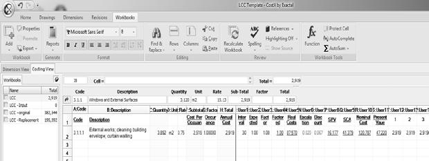
results. The key benefits to cost professionals are; the ability to complete an WLLCA without having to do any of the time consuming PV calculations within a customised CostX workbook; using the BIM interface to generate quantities and internal or external databases to cost them
[1] R. J. Cole and E. Sterner, "Reconciling Theory and Practice of Life-Cycle Costing," Building Research and Information, vol. 28, pp. 358375, 2000.
[2] C. Fu, S. Kaya, M. Kagioglou, and G. Aouad, "The development of an IFC-based lifecycle costing prototype tool for building construction maintenance," Construction Innovation, vol. 7, pp. 85-99, 2007.
[3] OGC, "Whole-life costing and cost management," OGC, London2007.
[4] BSI/BCIS, "Standardized method of life cycle costing for construction procurement, A supplement to BS EN ISO 15686 -5" B. S. Institute, Ed., ed. London: BSI, 2008, p. 100.
[5] L. Sabol, "Challanges in Cost Estimating with Building Information Modeling," Design and Construction Strategies, Washington DC2008.
[6] K. Sylvester and C. Dietrich, "Evaluation of Building Information Modelling (BIM) Estimating Methods in Construction Education," presented at the 46th ASC Annual International Conference, Wentworth Institute of Technology, Boston, Massachusetts, 2010.
[7] A. Pelzeter, "Building Optimisation with Life Cycle Costing - The Influence of Calculation Methods," Journal of Facilities Management, vol. 5, pp. 115-128, 2007.
[8] Eurovent. (2005, June 1st). Recommendation
concerning calculating of life cycle costs for air filters. Available: http://212.123.1.105/web/eurovent
[9] S. K. Fuller and S. R. Peterson, "Life Cycle Costing Manual for the Federal Energy Management Program," vol. National Institute of Standards and Technology, U. D. o. Commerce, Ed., 1996 ed. Washington, United States: US Government Printing Office, 1996, p. 210.
[10] BS-ISO, "BS EN 15868-5:2008 Building and constructed asset – Service life planning; Part 5
Life cycle costing,". Building and constructed asset - Service life planning, B. S. Institute, Ed., ed. London: BSI, 2008, p. 56.
[11] DavisLangdon, "Life Cycle Costing as a contribution to sustainable design: a common methodology – Final report," European Commission, Europe2007.
[12] RICS, "New Rules of Measurement 3 - Order of Cost Estimating and Cost Planning for Maintenance Works," RICS, Coventry2011.
[13] M. Clift, "Life Cycle Costing in the Construction Sector," UNEP Industry and Environmnet, vol. April-September, pp. 37-41, 2003.
[14] TG4, "Task Group 4: Life Cycle Costs in Construction - Final Report," European Commission, Europe2003.
[15] P. Gluch and H. Baumann, "The Life Cycle Costing (LCC) Approach: A Conceptual Discussion of its Usefulness for Environme ntal Decision Making," Building and Environment, vol. 39, pp. 571-580, 2004.
[16] D. Kehily, "Leveraging WLCC When Utilising Building Information Modelling Technolgies," International Journal of 3-D Information Modeling, vol. 1(4), pp. 40-49, OctoberDecember 2012
[17] A. Ashworth, "Estimating the Life Expectancy of Building Components in Life -Cycle Costing Calculations," Structural Survey, vol. 14, pp. 48, 1996.
[18] A. A. Ajibade and S. Venkatesh, "The Rocky Road to BIM adoption: quantity surveyors perspectives," in Joint CIB W055, W065, W089, W118, TG76, TG76, TG78, TG81 & TG84 International Conference on Management of Construction: Research to Practice, Montreal, Canada, 2012.
[19] J. Boon, "Preparing for the BIM Revolution," in Proceedings 13th. Pacific Association of Quantity Surveyors Congress: World Summit
for Quantity Surveyors and Cost Engineers. Building the Future Together, Malaysia, Kuala Lumpar, 2009.
[20] D. Mitchell, "THE 5D QS: Today's Methodology in Cost Certainty," in RICS
COBRA, Las Vegas, Nevada, 2012, pp. 11981206.
[21] D. Forgues, I. Iordanova, F. Valdivesio, and S. Staub-French, "Rethinking the Cost Estimating Process through 5D BIM: A Case Study," in Construction Research Congress 2012 , West Lafayette, Indiana, United States, 2012, pp. 778-786.
[22] O. A. Olatunji, W. Sher, and N. Gu, "Building Information Modelling and Quantity Surveying Practice," Emirates Journal for Engineering Research, vol. 15, pp. 67-70, 2010.
[23] I. Howell and B. Batcheler. (2005, December 15th). Building Information Modelling Two Years Later - Huge Potential, Some Success and Several Limitations. Available: http://www.laiserin.com
[24] S. Taylor and C. Bailey, "Unlocking BIM Data," Questant2011.
[25] D. Goucher and N. Thurairajah, "Advantages and Challenges of Using BIM: a Cost Consultant's Perspective," presented at the 49th ASC Annual International Conference, California Polytechnic State University (Cal Poly), San Luis Obispo, California, 2012.
[26] C. Eastman, P. Teicholz, R. Sachs, and K. Liston, BIM handbook : A Guide to Building Information Modeling for Owners, Managers, Designers, Engineers and Contractors , 2nd ed. Hoboken, NJ: Wiley, 2011.
[27] CostX, "Advanced Training Excercise BIM and 3D Measurement," Australia2012.
[28] N. Hourigan, "Improving the service provision of life cycle costing in Ireland's PQS offices," MSc., School of Surveying and Construction Management, DIT, Dublin, 2012.
[29] A. Whyte and D. Scott, "Life -cycle costing analysis to assist design decisions: beyond 3D building information modelling," in International Conference on Computing in Civil and Building Engineering , University of Nottingham, 2010.
[30] Z. Shen, R. A. A. Issa, and L. Gu, "Semantic 3D CAD and Its Applications in the Construction Industry - An Outlook of Construction Data Visualization," Lecture Notes in Computer Science, vol. 4781, pp. 461467, 2007.
17
Northumberland Road, Dublin 4E-mail:
sfraser@husseyfraser.comAbstract The papers considers how BIM can be adopted within the standard form construction contracts currently used for public works in Ireland. It is submitted that provision for BIM can be made with only minor amendments to the PWC suite of contracts by adopting a contract protocol similar to that proposed by the Construction Industry Council (CIC) in the UK.
Keywords BIM, Public Works Contracts, CIC Protocol
With over 75% of construction costs being spent in the field, imagine the cost benefits that could be realised if a detailed three dimensional model of a building could be used, before construction, to accurately detect and redesign all clashes and interference between different design elements. Or if dozens of site scenarios could be run on screen showing the development of the site over time in order to accurately determine the most efficient and effective positions for cranes. Or if “what if?” models could be run to show the effects on the works of diverting an underground river in a densely populated urban area. Or if a detailed computer model could be used to generate the most efficient commissioning strategy for a building. Or if a handheld device could be used to automatically order, in real time, the correct replacement part from the manufacturer when carrying out a snagging review on site. Or if a real time dashboard could be used to effectively monitor and manage the energy efficiency of a building and the building Safety File automatically generated at handover from information already held in the digital model. Or if all of the contracting parties on a project (employer, contractor and sub -contractors) could meet each week in order to watch a three dimensional visualisation of all of the site works planned for the following week and could discuss coordination, collaboration and safety management informed by this visualisation of next week‟s activities.
The above examples are not from the future but have all recently been cited by multinational contractors as to how they are using BIM or
Building Information Management now to deliver benefits such as increases in construction management efficiency of up to 70%, reductions in the duration of the works of up to 65% and reductions in waste during the works of up to 20% [1]
While these contractors note that the cost benefits to the project budget alone justify the implementation of BIM in the field, it is also worth noting that the UK Government (in its UK Construction Strategy 2011)[2] has mandated the construction industry in the UK to use BIM on all public projects by 2016. In „Growth Through BIM‟ by Richard G Saxon, CBE [3] the current perceived leadership in the UK in advancing a BIM strategy is seen as being a key factor in promoting the recovery of the UK construction sector and in enabling UK industry to compete more effectively in export markets.
The benefits of BIM, used progressively, are stated to include reducing the cost, time and uncertainty of design, construction and the operation of buildings, by making previously laborious, manual and repetitive processes quicker, automated and more accurate. Recently, following a review, the UK Government announced that BIM had contributed in saving the Government STG£1.7 billion last year on major projects, noting that Secondary School buildings in the UK now cost 40% less through better contracting and innovation [4]. Stephen Kelly, Cabinet Office Chief Operating Officer, noted that “It now costs 40 per cent less to build a secondary school in the UK, both through better contracting and innovation”. The important role of government
was highlighted by Chloe Smith, Minister for Political and Constitutional reform, who was leading the review and who noted that “........because we are such a large client we are able to encourage the industry to do it a bit differently and we see the industry responding, with things like BIM.”
The term “BIM” is inexact, however, it is now generally taken to refer to a wide and widening suite of working methods and processes which become possible when the built environment industries move to adopt the full benefits offered by digital data and the use of artificial intelligence. As stated by Saxon, “ Whilst 2D CAD allowed traditional practice to become more efficient, BIM suggests new practices altogether.” BIM is not a “one size fits all” solution but rather is the increasing use of digital data technologies with increasing levels of integration. It represents the adoption by the construction sector, some would say at long last, of technologies that have been adopted by other industries, such as manufacturing, many years ago. BIM is generally represented as showing a progression from Level 2 with federated, separate digital models to “iBIM”, a fully integrated model. This implies that each contributor‟s input during the construction process is merged in a single, consistent model environment held on the Web, whilst, at the same time, all contributions can be identified, tracked and audited. One of the key benefits of a BIM-enabled approach is that collaboration across the supply chain is supported and rewarded by each of the parties having a fuller and more up to date picture of the progress of the works. As noted by Saxon, by providing better visualisations of the works to be carried out and b y encouraging cooperation and coordination in the field it is also expected that the full adoption of BIM will result in far lower levels of conflict in the construction process.
A well documented example of collaborative working on a huge project was in the development of Heathrow Airport Terminal Five in which the entire project team worked off a single BIM for the design and construction of the buildings [5]
In addition, the regulatory environment is also changing. The EU Procurement Directive is to embrace BIM and is expected to be ratified by the European Parliament in October 2013 [6] and, in the UK and Ireland, the EU Construction Products Directive (CPD) became mandatory from 1 st July 2013 with the adoption of the Construction Products Regulations 2011. The CPD calls for
consistent and better product information to be made available with construction offerings. As part of its policy to encourage the adoption of BIM, the UK Government has issued guidance to product suppliers on how to provide product information for use in a BIM environment. This means that material specifications and properties can be fed directly into BIM models on a project and accurate calculations and predictions such as the temperature efficiency and carbon content of the building as well as automatic building regulation approval may become possible.
The UK Government is now pushing ahead with the adoption of BIM and, in order to deal with the legal issues arising, the Construction Industry Council has produced a BIM Protocol (CIC/BIM Pro 1st Edition 2003) (“the Protocol”)[7], which has been drafted to enable the production of Building Information Models at defined stages of a project. The Protocol is intended to be expressly incorporated into all direc t contracts between the Employer and the Project Team members. The text of a model amendment, which expressly incorporates the Protocol into direct contracts, is included in the Protocol as the model enabling amendment. The Protocol creates additional obligations and rights for the Employer and the Project Team Member (the Contractor), but does not create additional rights or liabilities between different suppliers.
The Protocol is divided into 8 Clauses and 2 Appendices as follows:
1. Definitions.
2. Priority of Contract Documents.
3. Obligations of the Employer.
4. Obligations of the Project Team Member.
5. Electronic Data Exchange.
6. Use of Models.
7. Liability in Respect of a Model.
8. Termination.
Appendix 1: Levels of Detail and the Model Production and Delivery Table.
Appendix 2: Information Requirements.
Clause 1 of the Protocol sets out „Definitions‟. This defines terms such as „Federated Model ‟, „Information Management Role‟ , „Information Manager‟, „Information Requirements‟, „Level of Detail‟, „Material, Model‟ , „Model Production and Delivery Table‟, „Permitted Purpose‟ , „Project Team Models‟, „Protocol‟ and „Specified Models‟. For example „Model‟ is defined as „... a digital representation of part of the physical and/or functional characteristics of the Project‟
Given the possible uses of data-rich BIM, the Protocol seeks to address areas of concern for
information providers. The Protocol uses a general concept of “Permitted Purpose” to define the licensed uses of the models. The Protocol aims to reduce the need for separate electronic data exchange agreements between the project team members by addressing the principal risks associated with the provision of electronic data, in particular, the risk of corruption, following transmission.
The Protocol defines the model s that are covered which are scheduled in Appendix 1, “The Model Production and Delivery Table (MPDP)” The Protocol requires the Employer to appoint a party to undertake the “Information Management Role”. The principal responsibilities of the “Information Manager” can be summarised as:
1. Managing the processes and procedures for information exchange on projects;
2. Initiating and implementing the project information plan and asset information plan;
3. Assisting in the preparation of project outputs, such as data drops; and
4. Implementation of the BIM protocol, including the updating of the MPDP.
The “Information Requirements” (IR) have been included at Appendix 2 of the Protocol so that project wide information requirements can be expressly incorporated into all Proj ect Team members‟ agreements. It is the responsibility of the Information Manager to agree and issue the IR, which should be prepared before the agreements are concluded.
The “Model Production and Delivery Table” (MPDT) is a key document, as it both allocates responsibility and preparation of the models and identifies the “Level of Detail” (LOD) that models need to meet at the project stages or data drops stated in the table. The Protocol also defines the priority of contract documents and states that, in the event of a conflict or inconsistency between the terms of the Protocol and any other documents contained in and/or forming part of the agreement, the Protocol shall prevail.
The Protocol provides for the granting of sublicences (and sub-sub-licences) to sub-contractors for the “Permitted Purpose” related to the Project.
Public contracts in Ireland are now procured under the Public Works Contracts (PWC) suite introduced in 2007. Whilst this suite of standard contracts does provide for electronic communications and the use of software it is primarily designed to facilitate the traditional contractual relationships. Moreover, the PWC
suite of contracts have been heavily criticised due to the fact that, far from placing risk on the party which is best placed to manage it (as was the stated intention), they have moved as much risk as possible away from the Employer and onto other parties (largely the Contractor). In so doing, the PWC suite of contracts has done nothing to assist the recovery of the construction sector of the Irish economy and indeed many would say that the PWC suite of contracts has contributed to continuing recession in the industry.
Many believe that the PWC suite of contracts has not delivered on the promises mad e at its introduction. For example, it was initially suggested that the new suite of contracts would improve outcomes by requiring the Employer to clearly set out its requirements prior to contract. In the event, the Employer does still not provide full information and the Contractor is left to deal with such shortfalls in information. In 2007, this author suggested that the PWC suite of contracts shifted the contractual balance too far in favour of Employers, could lead to increased confrontation and ultimately would not be to the advantage of Employers or Contractors [8] and [9]. In addition it was noted that the PWC suite of contracts contained none of the fundamental features of partnering as adopted in the UK.
With the stakes being very high as, for example, set out by Saxon, the question arises as to whether the adoption of BIM in Ireland can be facilitated within the PWC suite of contracts, perhaps with the use of a protocol such as that now proposed in the UK? In this regard, it is submitted that anything that contributes to the more effective and efficient delivery of projects is to be welcomed and may give substance to the somewhat weak terms of PWC sub-clause 1 –„Co-operation‟
In their paper entitled “Implementing Building Information Modelling in Public Works Projects in Ireland” by McAuley, Hore and West [10], the authors recommend that the Irish Government moves towards the legal mandating of BIM. The authors noted that the GCCC (now PWC) suite of contracts “...are not set up to promote collaboration and effectively through the transfer of risk create a hostile environment.” It was suggested that a “....collaborative approach can be achieved through the re-drafting of the GCCC suite of contracts to include use of BIM technologies”.
The paper by McAuley et al suggests that the most effective way of dealing with the barriers to BIM are to have “.....collaborative, integrated project delivery contracts in which the risks of using BIM are shared among the project participants”. The key legal areas to be addressed are identified as being:
1. Digital data protocols.
2. Coordination and reliance.
3. Project responsibilities and risks.
4. Copyright/ use of documents.
5. Contractual privity; waivers and indemn ities.
This author submits that all of the above key legal areas are effectively dealt with in the Protocol issued by the CIC, for example, point 4 above is dealt with in Clause 6 (Use of Models) of the Protocol and elsewhere therein. It is therefore not necessary to completely re-draft the PWC suite of contracts. On the contrary, BIM can be implemented within the existing PWC suite of contracts (including the PWC sub-contracts and conditions of engagement of specialists) by way of minor amendment and by appending the CIC Protocol or a similar document. This is of particular relevance given the stated intention of the Department of Finance to review the working of the PWC suite of contracts beginning in October 2013.
The PWC suite of contracts were conceived and drafted in a completely different economic environment and their adoption may be seen as a lost opportunity to move towards a more collaborative model of working in the construction industry. It is submitted that the adoption of BIM and other collaborative tools now could address some of the difficulties inflicted on the industry and the Irish economy by the PWC suite of contracts. The incorporation of the CIC Protocol (or something similar) in the PWC suite of contracts could facilitate a move in this direction sooner rather than later and allow the contractual risks to be allocated and managed in a more reasonable manner. Such a move may also assist in the recovery of the Irish Construction industry and may give the industry a competitive advantage when competing for international business.
As the sponsors of the PWC suite of contracts and the ultimate employer for the vast amount of civil engineering and building work currently being tendered in Ireland, the role of the Irish government is key. For example and as a first step, BIM competence could be mandated as a prequalification requirement on particular, appropriate public sector tenders. As a small, open, innovative economy with a strong ICT sector, the adoption of a BIM approach in Ireland may stimulate the Irish economy while also finally enabling the government to realise the benefits originally promised by the PWC suite of contracts.
It is submitted that there is now an opportunity for the Irish Government to consider the hard experiences of the six years since the implementation of the PWC suite of contracts and to move forward with a fairer contractual environment which will be of benefit to the economy as a whole. The changes should include
enabling the PWC suite of contracts to allow for the adoption of BIM
[1] Construction Information Technology Alliance (CITA), 7th Technology Series Seminar, Radisson Blu Hotel, Dublin, 24th July 2013.
[2] UK Government Construction Strategy, Cab inet Office, Government Publications, 31st May 2011.
[3] Saxon CBE, Richard. (2013) Growth Through BIM, Construction Industry Council, 25th April 2013.
[4] Construction News, 4th June 2013.
[5] http://www.terminal5.mottmac.com/services/v isualisationandmodelling/).
[6] Construction Manager Newsletter, 24th July 2013.
[7] Building Information Model (BIM) Protocol, CIC/BIM Pro first edition 2013.
[8] Fraser, S. Does Partnering Offer a Solution to the Public Works Contract Dilemma? , Engineers Journal, Volume 61: Issue 7/September 2007.
[9] Fraser, S. New Forms Shift Balance in Public Works Construction Contracts, Engineers Journal, Volume 61: Issue 6/ July/August 2007.
[10] McAuley, B., Hore, A.V and West, R. (2012) Implementing Modelling in Public Works Projects, Proceedings of the 9th European Conference on Product and Process Modelling, Reykjavic, July 25 – 27th 2012.
Halmstad University, Halmstad, Sweden
E-mail: niclas.andersson@hh.se
Abstract Implementation of BIM in the construction industry relies on sufficient knowledge and skills about BIM in order to gain momentum and success. Thorough understanding of the possibilities as well as challenges related to the application of BIM constitutes essential drivers for the adoption of BIM among all the industry actors throughout the construction process. Thus, there is a need for supply of knowledge and skills about BIM and its implications on the organisation, communication, management, business models etc. in construction. Accordingly, universities play an important role as a knowledge and skills supplier that helps to provide the necessary conditions for the implementation of BIM in the construction industry. This study investigates how the curricula of engineering and architectural teaching programs at Swedish universities and university colleges have responded to the apparent and increasing demand for BIM competences in industry. The study relies on a survey of 10 universities and 8 university colleges that provide engineering and architectural teaching programs at a master’s and/or a bachelor’s level. The findings show that bachelor’s engineering programs at university colleges generally have adopted BIM into the curricula to a somewhat larger extent compared to engineering programs at a master’s level. The BIM -adoption in architectural programs is, however, significantly limited. Further, the degree of BIM-adoption differs significantly between the respective teaching programs. Only few universities have adopted BIM as an integrated subject in courses that deal with general construction related issues. The predominant approach is to implement BIM-subjects as discrete teaching modules, i.e. stand-alone courses, rather than as a cross disciplinary aspect implemented in a number of the existing courses. Besides, a considerate mismatch is identified between the technical characteristics of the BIM curricula at universities and the process-oriented approach to BIM represented by the industry. Thus, the universities would benefit from a closer collaboration with the industry in BIM-related matters and they need to take on a strategic approach to BIM at an overall university or program level in order to avoid isolated BIM initiatives at a single course level.
Keywords BIM-adoption, curricula design, teaching programs, BIM objectives
The adoption of Building Information Modeling, BIM, among architects, engineers, contractors and other actors of the construction industry creates an increased need for supply of engineers and architects with profound knowledge and skills about the conception of BIM, how the technology can be used in industry, and not least how BIM can provide a catalyst for change and development of new work processes, business models, roles, services etc. The
implementation of BIM in the construction industry constitutes a thorough change process that requires development of innovative solutions as well as sufficient competences for all actors of the construction industry.
The issue of BIM-competence supply constitutes a highly prioritised area for the future BIM development and implementation in the construction industry [1]. Accordingly, university programs that relate to construction must react to and face the increased need for BIM-related competences in
industry and integrate BIM-subjects into the existing curricula [2]. Engineering education has been criticised for being too biased in favour of theory and disciplinary knowledge while too little attention has been given additional skills, e.g. personal, interpersonal, and professional skills [3]. The adoption of additional skills and subjects such as BIM and ICTapplications in general must be done without reducing the existing curricula of technical disciplines and still allow for the continuous acquisition of new technical knowledge [4].
BVU*net [5], a Danish non-profit organisation with members from educational institutions involved in construction and architectural teaching programs, states that the on-going development and implementation of BIM in the construction industry to a large extent is run without support or direct involvement from the universities. Thus, the BIM level in terms of competences and curricula adoption at universities is limited in comparison to the level of implementation in the construction industry [5].
The problem statement of this study refers to the scope and characteristics of the prevailing university teaching that relates to BIM and the question about how it corresponds to the requirements and expressed needs in industry.
The purpose of this study is to contribute to the understanding of BIM-adoption in university teaching programs by making a survey of BIM-related courses at universities and university colleges that provide construction related teaching programs. The findings of the survey will be reviewed in light of the BIM-objectives and needs expressed by the industry.
The empirical data collection is delimited to Swedish universities and university colleges that provide construction related teaching programs which includes civil engineering programs at the bachelor’s (B.C.E.) and the master’s (M.C.E.) levels as well as master of architecture (M.Arch.). The study used a somewhat broad definition of BIM and BIM-related subjects and includes courses dealing with e.g. traditional 2D CAD, Geographic Information System, GIS, urban planning modelling, CAD for HVAC-systems, computer supported structural design, and of course, concrete BIM- applications.
The survey of the BIM-related teaching at Swedish universities relies basically on a manual, hands-on, examination of the curricula of all engineering and architectural teaching programs. Thus, the survey
was done manually, supplemented with the use of internet search functions, by exploring the homepages of all Swedish universities, semester by semester, identifying courses that potentially could include BIM-related subjects. The learning objectives of all the identified courses that included BIM-related teaching aspects were analysed and documented.
Of course, a manual and partly subjective survey like this is likely to include mistakes. For example, courses that actually include BIM-aspects could be neglected if the title of the course did not indicate an obvious relation to BIM. Especially courses in which BIM provides an integrated learning objective rather than a main topic in itself could be ignored.
In order to validate that all BIM-related courses were covered in the survey, the list of all identified BIM-courses was sent by mail to all the study leaders of the respective teaching programs. All in all, the preliminary list of BIM-related courses was sent to 44 study leaders of which 9 replied with comments, corrections and supplementary information about their courses.
In this study, only universities and university colleges with teaching programs that relate to construction were considered. The survey included architectural schools as well as civil engineering programs at a bachelor’s and master’s levels. All in all, 10 universities and 8 university colleges with construction related teaching programs were identified and included in the survey. These educational institutions represented a total of 35 different teaching programs, which all together represented 92 courses with syllabuses that relate to BIM-subjects.
To critically review the relevance of the BIMcontents in engineering and architectural teaching, the curricula were to be analysed in light of the BIM-objectives expressed by the construction industry. This study decided to use a recently (in 2013) published strategic research agenda [1], initiated by IQ Samhällsbyggnad, IQS, [6] with support from OpenBIM [7] and Bygginnovationen [8], as the reference for the BIM-objectives and needs in industry. The agenda maps the current BIMstatus in industry, describes BIM-objectives and identifies important areas of future research and development with regards to the further application and implementation of BIM in the construction industry.
IQS is an independent, non-profit, member funded, organisation that works as an integrating hub between research, industry and politics in matters that relate to all aspects of the build environment. IQS has about 130 members representing public institutions, building clients, real estate owners, contractors, consultants etc.
IQS put together a project team with members from industry and universities to work with the
agenda. A reference group and a steering committee were assembled to support the project team. Altogether, 20 members of IQS were represented in the project team, reference group and the steering committee. Besides, during the work process the agenda has been presented and critically discussed at three public workshops with representatives from academia, industry, trade organisations, institutional organisations etc. The agenda was financially supported by Vinnova, [9], the Swedish Governmental Agency for Innovation Systems.
The argument for choosing this particular research agenda as a reference in this study is principally twofold. First, the agenda is produced and published in parallel with the empirical data collection of this study, i.e. the timing is perfect. Besides, the broad representation of the main stakeholders from industry, universities, authorities, trade organisations etc. provides a comprehensive, thorough and validated basis for the agenda.
The system of higher education in Sweden differentiates between universities and university colleges. The universities are research-oriented and are certified to award bachelor, master and doctor degrees in all academic fields. University colleges, on the other hand, are more into applied sciences and have a primary focus on the bachelor degrees. University colleges can, however, apply to the government for the entitlement to grant master’s and doctor degrees in limited and specific fields. [10, 11].
There are about 50 national institutions of higher education in Sweden, from Luleå University of Technology in the north part of Sweden down to Malmö University in the very south. 16 of those are full universities and 30 are university colleges. 11 of those university colleges have the rights to grant master and/or doctor degrees in specific fields. All higher education is offered by public sector institutions or by independent education providers that have been grated degree-awarding powers by the Swedish Government. 14 of the 16 universities are public sector universities and, consequently, 2 are independent universities. The distribution between public sector and independent university colleges is more equally distributes. 20 university colleges are public and 10 are independent. All higher education, at public sector as well as independent institutions, is free of charge for Swedish citizens and for citizens of the EU/EEA countries including Switzerland. [12]
The 35 different teaching programs included in this study were represented by 4 Master of Architecture (M.Arch.), 6 Master of Civil Engineering (M.C.E.) and 23 Bachelor engineering programs (B.C.E.). Two master programs represent a combined education that qualifies for a double exam in architectture as well as in civil engineering.
When mapping the total number of BIMrelated ECTS-credits (European Credit Transfer and Accumulation System) [13], it immediately becomes obvious that the vast majority of BIM-related ECTScredits are presented by B.C.E. programs. The bullet list below shows the percentage of the number of BIM-related ECTS-credits for each teaching program in relation to the total number of BIMrelated ECTS-credits (640 credits) for all the 35 teaching programs at a national level.
• M.Arch. 5% (34 of 640 credits)
• M.Arch. + M.C.E. 8% (50 of 640 credits)
• M.C.E. 17% (109 of 640 credits)
• B.C.E. 70% (448 of 640 credits)
One immediate observation when looking at the distribution of BIM-related ECTS-credits above is of course the significant differences between the M.Arch. and the B.C.E. programs. Thus, 70% of all BIM-related ECTS-credits are produced in a B.C.E. program and only 5% in an architectural program. Consequently, it seems correct to conclude that BIM-related subjects are not very well adopted in architectural programs in comparison to B.C.E. programs. However, the adoption of BIM must also be analysed considering the total number of programs and courses in the various teaching programs. The actual adoption of BIM-related ECTS-credits in the curricula of the various teaching programs compared to the total number ECTS-credits in each type of program show a more balanced distribution. The bullet list below show the percentage of BIMrelated ECTS-credits in relation to the total number of ECTS-credits for each type of teaching program:
• M.Arch. 3% (34of 1 200 credits)
• M.Arch. + M.C.E. 8% (50 of 600 credits)
• M.C.E. 9% (109 of 1 440 credits)
• B.C.E. 11% (448 of 3 960 credits)
The figures above indicate that the implementtation of BIM-related subjects in the curricula in B.C.E., M.C.E. and the M.Arch. + M.C.E. programs are at a more or less similar level and that the BIMadoption in M.Arch. programs is limited. Besides, a minor difference can be identified when comparing the percentage of BIM-related ECTS-credits at universities and at university colleges, regardless of the type of program. University colleges have an average of 13% of BIM-related ECTS-credits. The same figure for universities is 8%. Thus, it seems
that university colleges are ahead of the universities in terms of the level of BIM-adoption.
Another aspect identified in the analysis is the significant variance in the level of BIM-adoption of the various educational institutions as well as the teaching programs. The survey shows that the level of BIM-related courses at a university differs from the top level of 90 ECTS-credits, at the Luleå Technical University, down to the lowest possible level of 0 ECTS-credits at Umeå University. It should in this context, however, be mentioned that the total construction related ECTS-credits is more than the double at Luleå Technical University in comparison to Umeå University (1 020 compared to 480 ECTS-credits).
The same significant differences are recorded when looking at the level of BIM-adoption at the respective teaching programs. The Bachelor program of Building Engineering at Malmö University shows the highest adoption of BIM in its curriculum. In this particular program, as much as 39% of the total ECTS-credits, i.e. 70 out of a total 180 ECTScredits, include BIM-related subjects. The average percentage of BIM-related ECTS-credits related to the total number of ECTS-credits of all programs is 10%.
The second question raised in this survey is that of the conformity between the BIM-subjects taught in the existing university curricula and the BIMobjectives inquired by industry. The question answers to the degree of relevance of the teaching subjects at universities and aim at indicating the needs for the future BIM-adoption in university teaching programs.
This survey examined the expressed learning objectives in terms of knowledge, skills and attitudes of all the 92 courses that were identified as being BIM-related in one way or another. The learning objectives were categorised into four overlapping groups:
1 Aggregation levels: Construction (single project related issues) and Urban Planning and Landscaping (areal planning, GIS related issues)
2 Modelling levels: 3D or 2D and, syllabuses including 3D and 2D
3 Teaching subjects: Drawings (rendering of drawings from the model), Visualisation (communication and rendering etc.), IFC (information exchange between software platforms), Construction Management (4D, 5D, model validation, clash detection etc.) and Business Strategies (business opportunities, implementation and change processes, new roles and responsibilities etc.).
4 Construction process: Architectural Design (general aesthetic and functional design), Structural
Design (structural engineering, MEP etc.), Construction (production related issues construction management) and Real Estate Management (Facilities Management, operation and maintenance etc.)
The first issue of aggregation level shows the distribution of courses that deal with single project of buildings and constructions of all kinds in comparison to urban planning and landscaping, i.e. primarily GIS-related issues. The study finds that 86% of the BIM-related ECTS-credits concern construction of buildings and consequently, only 14% relate to issues of urban planning and landscaping (GIS). The study does, however, not take into account the total number of courses and ECTScredits in the respective categories of teaching programs.
Most BIM-related ECTS-credits include 3Dmodeling (66%), while courses that are delimited to 2D-modeling represent 22% of the total number of ECTS-credits. The remaining 12% are represented by courses that include both 3D- and 2D-modeling.
The mapping of subjects being represented in the identified BIM-courses is interesting in compareson to the competence needs expressed by the industry. The study found the following distribution of ECTS-credits (% of the total BIM-related ECTScredits) between the five categories of teaching subjects described above:
• Drawings (generation of drawings) 51%
• Visualisation (communication, rendering) 32%
• IFC (data exchange) 9%
• Construction Management (4D, 5D, etc.) 7%
• Business Strategies (implementation etc.) 1%
Obviously, more than 50% of the BIM-related ECTS-credits include learning objectives about generating architectural and engineering drawings from the 3D (and 2D) models. It is of course an important BIM-feature to be able to quickly update all drawings when changes are made to the model. However, the importance and representation of this aspect in the curricula must be considered overrated in relation to other BIM-objectives. Thus, despite the transformation into 3D-modeling (66+12% of all BIM ECTS-credits), the prevailing BIM-adoption in university teaching still rests upon the CAD-tradition and the conception that paper drawings provide the information platform in construction.
It is also worth noting that only 1% of the ECTS-credits, i.e. one single course, have matters of business strategies in relation to the implementation of BIM as its principal learning objectives. This crucial aspect of BIM-integration in existing as well as new processes, new forms of collaboration, new roles and responsibilities, new ways of communication etc., is clearly underrepresented in the university curricula.
The fourth issue relates to learning objectives that connect to the various phases of the construction process. The study shows the following distribution
of ECTS-credits (% of the total BIM-related ECTScredits) between the phases of the construction process described above:
• Architectural design 62%
• Structural design 14%
• Construction 18%
• Real estate management 6%
According to the figures above, the learning objectives that somehow relate to architectural design (62%) constitute the vast majority of the total BIM ECTS-credits. In this context architectural design includes all teaching activities dealing with general model generation. The design phase is, in this study, divided into architectural and structural design in order to illustrate the strong dominance for the architectural aspects of design in relation to structural design. The findings correspond to the previous observations of teaching subjects according to which the generation of drawings (51%) and visualisation (32%), by far provided the most prominent BIM-subjects.
Obviously, the adoption of BIM in the university teaching programs follows the successive progression from the initial design phase(s), through the phase of construction and on to the finishing phase of real estate management.
In order to critically review the relevance of the BIM-adoption in university teaching programs, the current BIM-curricula are compared to the BIMobjectives expressed by the construction industry. As mentioned in the Method section, the Strategic Research Agenda [1], SRA, for Building Information Modeling, established by IQ Samhällsbyggnad [6] will represent the BIM-objectives pronounced by the industry.
The SRA agenda provides a comprehensive review of the current BIM-situation as well as future objectives and visions for BIM-development. All in all, three areas are pointed out as being the most prominent for the future research and development:
• BIM Standards and regulations
• BIM-applications
• Supply of BIM-competences
The call for supply of BIM-competences is in line with the argument raised in this study, i.e. the need for universities and other educational institutions to provide sufficient and relevant knowledge and skills about BIM and its implications for the construction industry. Further, the continuous establishment of common standards, processes and formats provide an important basis for the future development and implementation of BIM in the construction industry.
The area of BIM-applications, which in this study provides the basis for the comparative analysis
between BIM-adoption in university programs and BIM-objectives in industry, includes the three subaspects of “BIM and process renewal”, “BIM and real estate information” and, “BIM implementation”. Altogether, a number of key issues and BIMobjectives that cover all phases of construction were emphasised in this context, e.g.:
• Process renewal
• Urban planning
• Design
• Production
• Industrial processes
• Real estate management
• Modeling the existing stock
• Implementation and change processes
• New forms of cooperation, incentives, contracts
• New business models, value chain
• New roles and responsibilities
The areas of BIM-applications included a large number of specific BIM-objectives such as visualisation, quantity take-off, light analysis, energy analysis, clash detection, simulations etc.
Two immediate observations can be made when reviewing the expressed BIM-areas and objectives in light of the BIM-adoption in university curricula. First, the industry expresses a wider scope of application, including in all phases of construction, with specific emphasis on the areas of urban planning and the real estate management. According to this survey, the predominant BIM-applications in the curricula of the teaching programs relate to design (architectural design, 62%, and engineering design, 14%), while urban planning and real estate management appear to be more or less neglected in the BIM-curricula of today.
Secondly, the learning objectives of BIM courses typically have a primary focus on discrete features, i.e. generation of drawings, visualisation, etc. Besides, BIM-courses appear to be designed as standalone silos, i.e. isolated from courses dealing with other subjects of disciplinary knowledge. Thus, the nature of BIM as an integrator, connecting the various processes and the information flow between the actors involved, is not prevalent in the university curricula. Industry, on the other hand, pronounce the importance of change and process renewal with focus on new business models, forms of collaboration, communication, integrated value chains, etc.
Thus, there is a gap between the BIM curricula of the universities and the BIM-objectives expressed by industry.
The study finds that all construction related teaching programs, only with few exceptions, have adopted BIM in their respective curricula. Engineering Bachelor programs at university colleges have the highest general representation of BIM-subjects in the
curricula. The BIM-adoption in architectural schools is, however, significantly limited.
Further, the degree of BIM-adoption differs significantly between the respective teaching programs, which can be explained by different adoption strategies applied by the universities. Only few universities have adopted BIM as an integrated subject in courses that deal with general construction related issues. The predominant approach is however to implement BIM-subjects as discrete teaching modules, i.e. stand-alone courses, in which BIM is regarded a technical tool rather than a facilitator for process integration and organisational development.
Thus, there is a considerate discrepancy between the technically oriented BIM curricula at the universities and the more process and change oriented approach to BIM represented by the industry. Besides, the industry emphasises the importance of BIM-implementation in urban planning and real estate management, which currently is more or less neglected in university curricula. The study concludes that the industry, primarily represented by large consultancies and contractors, is driving the BIM-movement and is ahead of the universities in terms of BIM awareness, maturity and competences.
Accordingly, the universities would benefit from a closer collaboration with the industry on BIM-related matters. Besides, the universities need to establish a strategic approach to BIM at an overall university or program level in order to integrate BIM as a cross-disciplinary subject in the curricula and avoid discrete BIM initiatives in stand-alone courses.
[1] IQ Samhällsbyggnad. “ICT-BIM för hållbart samhällsbyggande - en forsknings- och innovationsagenda för ökad svensk konkurrenskraft”. (in Swedish) www.iqs.se/Verksamhet/Vara_projekt /~/media/Files/Projekt/Agenda_ICTBIM/130430_Agenda_ICTBIM_slutlig_version.ashx, 2013.
[2] R. Batista and C.V. De Carvalho. “Work in progress - Learning through Role Play Games ". 38th ASEE/IEEE Frontiers in Education Conference, pp. T3C7-T3C8, 2008.
[3] S.D. Sheppard, K. Macatangay, A. Colby and W.M. Sullivan. “Educating EngineersDesigning for the Future of the Field”, The Carnegie Foundation, Jossey-Bass, USA, 2009
[4] N. Andersson and P. Andersson Hammar. “Building Information Modeling in engineering teaching - Retaining the context of engineering knowledge and skills ". Proceedings of the CIB W78 2010: 27th International Conference –Cairo, Egypt, 16-18 November 2010, 2010.
[5] BVU*net: http://bvunet.dk (2013-05-22)
[6] IQ Samhällsbyggnad: www.iqs.se (2013-04-20)
[7] OpenBIM: www.openbim.se (2013-05-11)
[8] Bygginnovationen: www.bygginnovationen.se (2013-05-11)
[9] VINNOVA: www.vinnova.se (2013-05-11)
[10] Study in Sweden: www.studyinsweden.se (2013-06-06)
[11] The Swedish Council for Higher Education: www.uhr.se/sv/Studier-ochantagning/Antagning-tillhogskolan/Hogskoleforordningen (2013-06-06)
[12] A. Amft, ed. “Swedish Universities & University Colleges - Short Version of Annual Report 2012". Report 2012:18 R, Swedish National Agency for Higher Education, 2012.
[13] European Commission. “European credit transfer and accumulation system (ECTS)Key features". Office for Official Publications of the European Communities, Luxembourg, Belgium, 9 pp. 2004.
School of Surveying & Construction Management
Dublin Institute of Technology, Dublin
E-mail: avril.behan@dit.ie
Geomatics Surveyors are often the first professionals to work on construction and redevelopment sites as well as being present throughout the building and commissioning phases of many AEC projects. As a result, they have the potential to play an important role in any BIM project team. This paper presents the recent, current, and planned elements of Geomatics education at the Dublin Institute of Technology relevant to BIM.
DIT’s Geomatics students have, for the last 6 years, been educated in the principles of Building Information M odelling and in its application to both the building and infrastructure divisions of the AEC sector through theoretical instruction in a range of concepts and practical application facilitated by Autodesk’s Civil 3D software. Other elements of the Geomatics programme which are relevant to the efficient usage of BIM in industry include a wide range of spatial data acquisition techniques (static and mobile ground-based as well as remotely sensed from the air and space) as well as data handling and management methods which prepare graduates for the realities of working between multiple s oftware packages as required by a modern BIM project . Each of these are presented in detail in this paper with the conclusion that recent and future Geomatics graduates can greatly assist their fellow construction professionals in leveraging BIM for the ir mutual benefit.
Keywords Geomatics, Education, BIM, Autodesk
In the AEC sector Geomatics Surveyors are frequently thought of as rebranded land surveyors whose only function is to carry out the tasks of preworks site surveying and levelling, building setting out, and as-built surveying. In this context, surveyors have the advantage of typically being one of the first professionals on site (although not necessarily on the ground thanks to improved remote sensing techniques) for both new construction projects and for redevelopment activities. During this initial phase, it is the surveyor’s role to reproduce the site and its contents as a base for all subsequent design and planning, a very important and, possibly, underrated contribution to the BIM process. While the aforementioned functions can still be part of a geomatics surveyor’s remit when operating within the AEC industry, the surveyor’s skill set is much broader, as will be presented in the following, and holds much more potential for the application and development of BIM. Geomatics is actually an element of the Spatial Information Sciences industry which, while including construction engineering, has
application in a wide variety of sectors, as can be seen in Fig. 1.
Geomatics encompasses the activities of land surveying, geographic information science/systems (GIS), global navigation satellite systems (including GPS), photogrammetry & remote sensing, cartography and many other location-based domains [1]
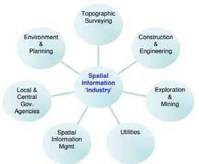
On DIT’s 4-year honours BSc. in Geomatics (Surveying and Mapping), students are educated in all of these areas, both from the perspective of the technologies and systems required, e.g. total stations, laser scanners, aerial & terrestrial cameras, Geographic Information Systems, etc., and from the application perspective, e.g. through modules such as Spatial Information Applications.
The cross-sectoral roles for which geomatics surveyors are educated and in which they operate offer many advantages in relation to the adoption and efficient usage of Building Information Modelling techniques, as will be explained in the following.
Since the widespread adoption of electronic total stations by surveyors in the 1990s [3], all survey measurements are captured in full three-dimensions thus producing a virtual, digital copy of the ground and all elements on it (and, more recently, below it as a result of the adoption of underground, geophysics-based surveying techniques [4]). Through the use of appropriate software, frequently integrating CAD, the surveyor could produce 2D plans, sections and a range of other client-requested drawings. For many projects 2D products, either on paper or in digital form, were the only deliverables requested by and/or delivered to clients. This meant that significant volumes of valuable data were never properly leveraged in the later stages of design and development. Particularly for refurbishment projects where existing buildings were adapted during the construction process much of the original site survey could have been used for production of as -built drawings to meet with safety requirements and to enable facilities management. However, in the preBIM era, where joined-up-thinking and data sharing was frequently absent, independent “3D” building surveys were often commissioned post-construction work thus creating unnecessary repetition and significant cost.
The availability of high-density, accuratelymeasured 3D survey data has recently increased significantly, particularly in the last 4 to 5 years, due to the maturity of laser scanning and other point cloud-based technologies. These methods have now become the de facto standard for a wide range of surveying tasks, including pre-works site and building measurement, building erection control, and as-built surveys. Before the arrival of BIM, discussions amongst surveyors at trade conferences attended by the author often focussed on methods of encouraging clients to leverage the volumes of high-
quality 3D data and potential information being collected by the latest instrumentation rather than continuing to adhere to traditional outputs such as 2D plans, sections and elevations, and methods based upon them such as quantity take -off. However, until recent advances in software, particularly in efficient graphics engines, and computing power, many surveyors’ clients saw the point cloud as nice to look at but unmanageable in practice.
The introduction of BIM processes to the construction industry provides a pathway through which the full power of 3D surveying, using traditional point and line collection methods or newer point cloud technologies, can now be more properly utilised throughout a project’s lifecycle.
A look at any medium- to large-size geomatics surveying company’s provisions list will show BIM among the services that can be provided. Obviously, the levels to which that service is available vary significantly from providing point clouds or other survey data in formats that are compatible with BIM software to full 3D modelling of existing sites, buildings and/or infrastructure in a relevant software application, support for the setting -out elements of field BIM, and post-construction surveying.
A 2006 report by the US Practice, Education and Research for Sustainable Infrastructure (PRESI) group on Geomatics for Sustainability highlighted the integration of BIM into Geomatics Education as a key deliverable in addressing the AEC sector’s challenges of an aging and failing infrastructure, declining productivity, and increased difficulties in relation to information sharing between stakeholders in infrastructure projects [5]. Taking account of the slower adoption of BIM in Europe (as indicated by the July 2013 discussions on enshrinement of BIM elements in the EU-wide Procurement Directive [6] and as one of the 36 Action Points for Ireland's Construction Sector: Outlook and Strategic Plan to 2015 [7]) and acknowledging differences between the infrastructure and pure construction sectors, this report recognises that appropriate education of Geomatics surveyors in relation to BIM is essential to the success of AEC sector recovery
DIT’s Geomatics BSc delivers education relevant to BIM from both theoretical and practical perspectives
and with particular emphasis on the management of spatial data and information
Within the Geodetic Surveying suite of modules, which run from 1st to 4th year of the programme, students learn survey methods that can be applied to the AEC and infrastructure sectors including selection, utilisation and basic maintenance of appropriate instrumentation and software. This includes 3D site and building surveying, setting out and dimensional control, and utilities mapping using a range of equipment including ultra-high speed and long-range laser scanners, GNSS receivers, total stations (now moving towards classification as multi-stations due to the integration of total station, GNSS and laser scanning capabilities [8]), and digital levels.
Particularly in relation to retrofit or refurbishment works, the starting point of any BIM project is the procurement of accurate 3D measurements of existing elements. The skills learned by Geomatics students in their Geodetic Surveying modules enable them to provide this information. By also educating students in the BIM process they can apply these skills to the provision of survey data and derived products, up to and including the full BIM model as required by the BIM project team for all stages of the project’s life cycle.
In 2007, significantly before BIM started to gain traction both in the Irish AEC and relevant education sectors, the programme team of DIT’s BSc in Geomatics (the only Geomatics programme in Ireland) made the decision to supplement teaching of 2D and 3D AutoCAD with Autodesk’s civil engineering design and documentation BIM software, Civil 3D. Previously students had worked in 2D CAD during the first ye ar of study and moved into 2.5D (appropriate for topographic surveys) and 3D (building surveys) during 2 nd and subsequent years. Even then, because of the importance of ensuring accuracy in all measured surveys, and of direct relevance to the software elements of BIM, the 3D CAD elements emphasised the detection and avoidance of clashes in solid models. In the 3 rd year students also undertook processing and limited modelling of point clouds derived from terrestrial laser scanners in Trimble Realworks.
Autodesk’s Civil 3D software combines tools for the semi-automatic download and management of survey data with civil engineering design tools within a GIS-based (Geographic Information
System) environment where landscapes can be modelled, visualised and analysed to facilitate enhanced decision-making, particularly at project planning and design stages. The software is, like BIM and GIS, centred on a database where thematic information is directly linked to 3D spatial locations. Changes in the database result in changes in the model and vice versa.
Civil 3D has the added advantage for surveying of directly linking the original field survey via a database to the 3D model. The link works in both directions meaning that a survey can be carried out of an existing building and site; the data downloaded semi-automatically with appropriate coding into the survey database; imported into the BIM model; edited for visualisation and interpretation purposes; used as a base for new designs; exported from the model, via the sur vey database, back to survey instruments and the new content set out directly in the field, thus facilitating real Field BIM. For small changes, such as on-site changes of mind or the now unlikely clashes, such a process can be carried out in almost real -time due to the direct download capability of survey instrumentation over WiFi, phone networks and Bluetooth.
In September 2013 a change has been implemented for delivery of CAD/BIM over the first 3 years of the BSc programme to introduce BIM during the 2nd half of the first year thus creating more space in the 3rd year to allow students expand their education in laser scanning processing, and to gain some experience with using other BIM environments, such as Autodesk’s Revit, and visualisation tools such as 3D Studio Max. It should be noted that 3D data processing is not limited to pure CAD environments. All major survey equipment manufacturers produce software suites which adjust, manage, and visualise field data as well as handling export to a range of ot her applications.
GIS is another object-oriented system where the spatial locations of objects are linked to a wide variety of thematic information via a Geodatabase. These systems facilitate visualisation and spatial querying of interrelated data such as investigating the best location for a new facility taking account of ground topography, demographics, zoning, environmental factors, etc.
The alignment between GIS and BIM is significant, particularly in infrastructure projects, as both methods/systems facilitate better decisionmaking and life-cycle management through the integration of a range of different information resources in a readily-accessibly manner.
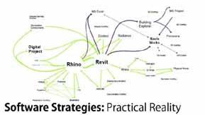
As previously mentioned, although geomatics surveyors are often among the first professionals to start work on a project, developments in remote sensing techniques (measurement of objects from remote platforms without contact) now mean that initial site surveys, particularly for greenfield sites, can frequently be carried out by aerial- or satellitebased sensors. These systems include traditional photographic, infra -red or radar methods from nearearth orbit satellites, planes, helicopters, Unmanned Aerial Vehicles (UAVs), or even kites or balloons.
For the planning and design stages of BIM projects, as typified by the Aviva Stadium project in Dublin [9] after 2005, the area surrounding the site can often be of as much importance as the site itself when undertaking daylight studies to investigate the effects of different structure forms and footprints. Remote sensing is frequently the best way of obtaining detailed information about a site’s surrounding in a cost effective manner and GIS software is typically the best tool for managing information from a range of data sources.
What this review of the BIM-related content of DIT’s Geomatics programme has not yet emphasized is the importance of data integration. As highlighted previously by PRESI, the management and merging of data between different data sources and systems is one of the biggest challenges faced by the AEC sector today. While BIM makes significant strides to redress this problem, the reality is still that no single software solution is able to entirely manage a BIM project. In his research on using Games as Design Environments at Harvard University’s Graduate School of Design, Benjamin Regnier formulated this image (Fig. 2) of the practical reality of modern design environments.
From the beginning of their studies Geomatics students are required to manipulate spatial data in a variety of software tools, sometimes 4 or 5 in a single project, to achieve end products appropriate to client requirements as would be typical of the real world. In the third year of the programme at least 12 weeks are spent on industrial placement and this period demonstrates clearly to students the necessity of building skills in the data integration area and, along with their final -year thesis, provides them with an opportunity to do so.
This skill is readily-applicable to the BIM process and further emphasises the contribution that Geomatics professionals, including new graduates, can bring to the BIM project team
The Geomatics programme at DIT is in continuous review both internally via the programme committee and DIT’s Quality Assurance procedures and externally via the relevant accrediting bodies of The Society of Chartered Surveyors Ireland (SCSI), The Irish Institution of Surveyors (IIS) and The Chartered Institute of Civil Engineering Surveyors (ICES). Annually changes are made to reflect market demand and DIT is committed to ensuring that Geomatics students have a solid foundation in BIM principles and a working knowledge of their application.
The point to emphasise for all BIM adopters is that all recent, since ~2008, and future graduates of DIT’s BSc. (Hons) Geomatics (Surveying & Mapping) have been educated with the necessary skills to be valuable, contributing members of project teams. Including Geomatics Surveyors from the outset in BIM project teams, both for greenfield and refurbishment works, has the potential to significantly benefit the overall project both financially and in terms of improved workflows. Geomatics Surveyors may only recently have started to adopt BIM terminology but for the last 20 years full 3-D recording and measuring has been their standard
[1] C. D. Ghilani, P. R. Wolf, and K. Srinivasa Raju, Elementary surveying : an introduction to geomatics, 13th ed. Upper Saddle River, N.J.: Pearson Prentice Hall, 2012.
A key element of Geomatics education is the appropriate and reliable handling of spatial data.
[2] F. T. Prendergast, W. P. Prendergast, A. F.
Behan, and H. Murray, "Enhancing Educational Programmes for Geomatics in Ireland," presented at the International Congress on Geomatics Education in Europe, Warsaw University of Technology, 2007.
[3] A. Bannister, S. Raymond, and R. Baker, Surveying, 2nd ed. Harlow, Essex CM20 2JE, England: Pearson Education Ltd., 1998.
[4] P. J. Gibson and D. M. George, Environmental applications of geophysical surveying techniques. New York: Nova Science Pub., 2004.
[5] Practice Education and Research for Sustainable Infrastructure, "Geomatics for Sustainability," PRESI2006.
[6] Construction Manager. (2013) Brussels set to enshrine BIM in EU-wide procurement directive. Construction Manager. Available: http://www.constructionmanager.co.uk/news/brussels-setenshrine-bim-eu-wide-procurementdire/?goback=.gde_1920603_member_25 5048828.nmp_*1_*1_*1_*1_*1_*1_*1_ *1_*1_*1
[7] Forfás, "Ireland's Construction Sector: Outlook and Strategic Plan to 2015," Forfás2013.
[8] Leica Geosystems. (2013, June). Leica Nova MS50. Available: http://www.leicageosystems.com/en/Leica-NovaMS50_103592.htm
[9] C. M. Eastman. (2011). BIM handbook: A guide to building information modeling for owners, managers, designers, engineers and contractors (2nd ed.)
[10] B. Reigner, "Games as Design Environments," MSc, Graduate School of Design, Harvard University, 2011.
E-mail: 1oliver.kinnane@tcd.ie 2rwest@tcd.ie
Abstract The lack of a BIM module in the curriculum of civil engineering students has the potential to deprive graduates of a necessary competitive advantage in a difficult job market. This paper outlines the introduction of BIM into the curriculum of Civil and Structural Engineering courses at Trinity College Dublin. BIM has this academic year been introduced into the 4 th year of the curriculum via two project-focused modules.
The projects involve the detailed design of pedestrian bridges on chosen sites along the Wicklow Way walking trail (a 4th year project module) and the group design of a new mixed-use urban quarter for Dublin, with detailed design of individual buildings on site by each student (in a Design for the Built Environment course). Together these projects enable the student develop a holistic understanding of BIM across a wide range of scale and detail. They are introduced to its full range of functionality, and its interoperability with sister analysis software through active project-focused learning.
In the case of the bridge design project, students are first educated in concepts of bridge design, context and building intervention in sensitive environments through theory discourse Active learning of BIM software follows via bridge design (using Revit 2013 and Civil 3D) and structural analysis of the bridge designs (using Robot). Given that BIM software is currently very much focused on building design, students are required to bespoke model the landscape context and many of the components of the bridge structure and investigate workarounds to create their designs.
In the case of the urban neighbourhood and building design project, students are first educated in the core concepts of sustainable urban and building design via lectures and associate d best practice example presentations. Active learning of BIM software follows via civil engineering design of the brownfield site (using Civil 3D), and development of individual building designs (using Revit 2013). With collaborative and collective effort, the students bring the individual building designs together to create an urban quarter populated with sustainable buildings. The site model, along with the individual building models, are uploaded to the cloud (BIM 360) and each building design is placed onsite to enable the development of a complete BIM neighbourhood model. Civil and transport infrastructure is incorporated to provide for the estimated 5,000 inhabitants of the site. Analysis of the BIM model at the neighbourhood and building scales enables the students to understand integrated design for the built environment at its various scales of impact.
The reaction from students to the outlined method of BIM education has been positive. BIM has proved an excellent platform from which to investigate engineering design concepts within the confines of a very full curriculum. In-depth understanding of the technical and business functions of BIM and its wide range of analytical ability will allow engineering graduates emerge with necessary skills and com petitive advantages to respond to inevitable IT innovations in a depressed construction market.
Keywords BIM, engineering education, design thinking
This paper outlines two modules for 4th year Civil and Structural Engineering students. Both are project focused modules and BIM software is the medium for delivery of the resulting project designs. The modules are:
1. A 4th year project module (10 ECTS credits)
2. A design and the built environment optional module (5 ECTS credits)
Neither module is purely a BIM skills learning course in the mould of a standard engineering CAD or drafting class. Rather the modules promote a more conceptual approach to engineering communication via two design projects. The engineering theory underlying the design projects is delivered via design lectures and students are requested to adopt these theories in their project designs.
Therefore the modules may be viewed as courses in communicating engineering information, in which BIM is a key element.
Both projects follow similar appoaches, with two principal components:
1. Initial design as part of a group project,
2. Individual detailed design project.
The focus of the 4th year project module is the design of a pedestrian bridge along the Wicklow Way hiking trail. The second phase of this project emphasises detailed focus on an aspect of the bridge design of the individual students interest (e.g. life cycle analysis, durability, structural analysis etc.)
In the case of the built environment design project, the initial group phase focuses on the design of a sustainable urban scale development. The second phase involves the design of an individual building of student choice on the site.
The modules and learning outcomes are outlined in greater detail in subsequent sections. Pertinent examples of each project are presented which display the student’s use of BIM in the design process.
3D modelling has for years now been an established requirement in Mechanical Engineering courses in university [1]. In Civil Engineering courses the urgency for change to 3D modelling has been less necessary and appropriate, however BIM is now inspiring a change from 2D representation to 3D. Many universities now have begun to include BIM
in their Civil Engineering curricula, some even making it part of Freshman curricula [2]. CAD remains part of many courses, appearing as the basic skill, while BIM is perceived as a more sophisticated or complex subject [2].
The students under consideration in this paper possess basic CAD skills learned during Junior Freshman and have no previous BIM experience.
‘Active learning’ is an education method that refers to the focusing of responsibility of learning on to the learner. It is a technique that has gained popularity in engineering and the sciences [3] [4]
Similarly ‘design thinking’ is a commonly used expression in contemporary engineering education, and one promoted by Engineers Ireland [5] The objective is for engineering students to view challenges through a fresh lens of creativity, in order to then unlock innovative solutions.
‘Sustainability’ has emerged as a significant driver of future engineering practice. Engineering a sustainable built environment is a predominant challenge facing graduates of engineering
Active learning and design thinking are defining concepts of the education described in this paper. The extensive and multi-dimensional nature of BIM makes it an excellent platform for students to engage in synthesis, analysis and evaluation - all key to an active learning education [6] – of their own designs.
A definite benefit of the initial group stages of each project was that teamwork skills were honed by working as part of an interactive design group. In design schools, design is generally a solo operation [7]. This can be even more pronounced in engineering schools where students are observed to go to lengths to divvy up work to ensure working alone [8]
BIM and sustainability are claimed to be symbiotic forces sweeping through the AEC industry [9]. BIM enables a good medium for maximising the potential of can aid in performing complex building performance analyses to ensure an optimized sustainable building design. BIM also
This module is a popular 5 credits module, titled “Design and the Built Environment”. It is an optional module that was taken up by all members of the Senior Sophister class. This semester the module
was redesigned. The previous focus was on topics such as archeology, history of architecture and fire engineering. The new module focuses on such topics as:
• History of design and the built environment,
• Sustainable urban design,
• Sustainable and passive building design,
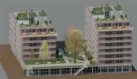
• Energy efficient buildings.
These topics are introduced via theory discourse and students are challenged to adopt concepts from design history and sustainable design principles in their design projects.
A brownfield, and politically notable site (the former Irish Glass Bottle Site), was chosen as the location for the sustainable urban quarter.
For context, examples of past and flawed urban development (European mass housing, American housing projects, suburban sprawl etc.) were introduced to contrast with contemporary concepts of sustainable urban projects
The development was planned as a student village to cater for students of both TCD and UCD given its location almost equidistant from both universities

The site design developed by the class emphasises compact, mixed-use, permeable and pedestrian priority development. A radial pattern was chosen with large public space and access to the waterfront and adjoining green areas (Fig. 1)
student accomodation, the student Omar Atik aimed to design accomodation with ample room proportions, enabling high levels of occupant comfort and incorporating extensive garden space (Fig. 2).
The second phase of this module project involved the design of individual buildings by students. Buildings included; multiple student accomodation, retail, leisure facilities, cinema, market, transport hub, creche and bars.
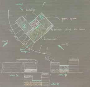
The site was planned to accommodate 5000 students hence a number of buildings catering for high density student accomodation were required. Unsatisfied with the ubiquitous poor quality of
The building was orientated 15° south south-east to ensure no shading of the neighbouring buildings, to maximize views to Sandymount beach and to optimize passive solar gain and daylighting. Students were requested to develop their design concepts by sketching out their ideas before using computer-modeling tools (Fig. 3). Submission of sketchbooks was advised and extra credit was given to those students that submitted sketchbooks that documented their conceptual thoughts and design development.
Omar’s project was one of the most successful of the projects given that he used both the modelling and analysis (Fig. 6) functionality of BIM to good effect He developed innovative solutions to optimise his design where other students reverted to the options available within the set of families. Omar investigated parametric modelling to develop a bespoke curtain wall for the atrium of his two buildings (Fig. 4) Detailed construction drawings were also submitted for this project (Fig. 5).
Kristian Fitzgerald also focused on the design of a high
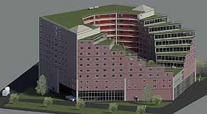

The building design went through a number of iterations before a final design was arrived upon . Kristian began with the form shown in the top left of Fig. 8. Shadow studies of conceptual masses enabled assessment of the appropriate geometry to maximise daylighting and solar gain for all apartments The building form was adapted based on analysis of the sun studies and the evaluation of the associated energy load of each building This interative design process was promoted so that students could justify the design decisions made, and not just choose a building design solution without reason.
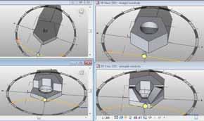
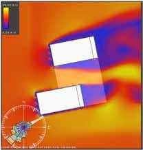
Tiered apartments were orientated to the south to enable natural daylighting penetrate the inner courtyard and the surrounding apartments (Fig. 9).
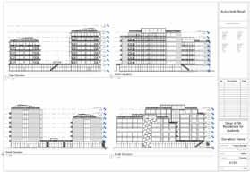
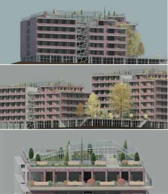
An iconic building was proposed for the south-east corner of the site, where the proposed Luas extension would enter. The site plan defined a triangular entry site with restricted dimensions. The student Paul Mc Goldrick proposed an innovative solution that optimised the space available on site yet created an imposing cantilevered prolongation over train and pedestrian entry ways.
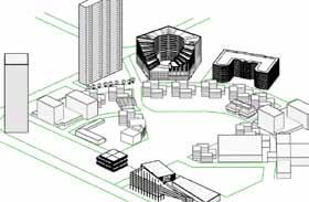
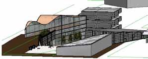
All building designs were linked to a central site model (Fig. 13). Due to computational memory resource isses early conceptual mass models were included first. Each student could then remove their conceptual mass and input their final design to understand their building in context and analyse it relative to the surrounding buildings. This enabled analysis of overshadowing, access issues etc.
Like all students Paul analysed his design decisions using Ecotect and Green Building Studio (Fig. 11 & 12). Based on this analysis he optimised the form and glazing proportions. Carbon emissions due to building operation and the associated heating loads of the building are shown below. An energy analysis of the models accounted for 33% of the project marks.

The module is a 10 ECTS two-semester long project. It is designed to replace the previous “final year project” due to the imminent change of the TCD engineering degree to a 5 year integrated program
A conceptual design project was completed by all students (as part of 5 person teams) during the first semester of the year. This culminated in the presentation of planning document. The designs were expected to be sensitive to the local environment with a strong emphasis placed on an enviromental impact study of the proposed development.
During the second semester approximately 33% of the class go on industrial work placement, and other students choose to focus their projects on their own areas of interest (transport, environmental assessment etc.). Those students with a focus on design and structures complete a detailed design project, individually, during the second semester of the year The specific BIM skills the student is expected to acquire vary from project to project depending on the educational focus of the student. Rather than fulfilling a set list of tasks the student is challenged to find the most appropriate BIM usage for their individual project.
Examples of different learning focuses of students include:
• Detailed bridge design and bespoke component design
• Structural analysis of bridge design

• Embodied energy evaluation of bridge designs.
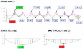

This project proposed a rerouting of the Wicklow way away from the busy road on which the trail currently follows and onto a dedicated path and river crossing at the mouth of the scenic Lough Dan (Fig. 14)
Student Michael Shine proposed a catenary bridge design to limit the obstruction to views from the deck down the river or of Lough Dan (Fig. 14) Michael’s concept sketches capture his design intent well (Fig. 15). The rendered designs compliment this concept well and capture the slenderness and nonobtrusive design intent (Fig 16-18),.
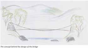
The objective was to employ BIM’s advertised interoperability to analyse the bridge model, designed in Revit, in Autodesk Robot. However, after investigation the student instead created simplified models in Robot of beam and deck structures and analysed these. The beam bending moments and shear force diagrams are shown in Fig 19

This second project is included to demonstrate the contrasts between student designs and the different ambitions of the students. This project proposed an iconic cable-stayed bridge with a 60m span at a river crossing on the Wicklow Way.


This student had more success analysing the full bridge in Robot structural anlysis. However, there is a suspicion that this bridge design was chosen for its appropriateness for the analysis software rather than out of any real intent to create a bridge appropriate for purpose and in the context of the site. This student stated that he does not see himself as a designer and seemed somewhat dismissive of the design component of the project. However, his designs in both this and the building design project show a good rationality and functionalism. His analysis of these designs was also very conclusive.
on developing personalised innovative structural solutions.
Documented here are two different design solutions for the same initial bridge design concept These are included to demonstrate the strong individuality and innovative thought of the students. The original design concept of the “fallen tree in the forest, spanning a river” is shown in Fig. 22.
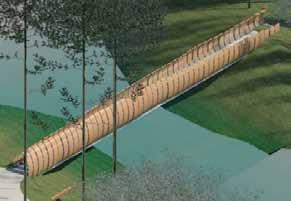
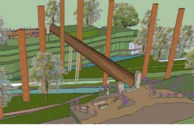
As previously described, students worked in groups in the first semester which culminated in the presentation of team a planning document for a single desing. In the second semester they focused
The student Patrick Ryan’s final design resolution is shown in Fig. 23. Patrick focused his detailed design on the development of a bespoke cladding system for the bridge that enabled views and shelter along its deck length. Patrick used a reinforced concrete structure to span the full length of the river. He used the sectional visualisation abilities of BIM to good effect to display the logic of his structure (Fig. 24).
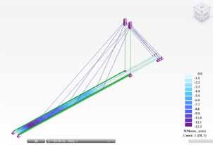
The second student Stephen Neary instead aimed for a reduction in the design and construction complexity (Fig. 25). He instead focused his project on the construction optimisation of the bridge cladding to enable reduction of materials used and hence a reduction of the embodied energy. Stephen developed a design solution based on 4 sections of prefabricated cladding (Fig. 26), with 2 vertical columns to support the bridge. The section through the bridge captures the simplicity of the design (Fig. 27).
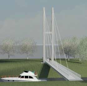
The students’ reactions to the two project modules were evaluated using an annoymous survey.
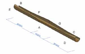
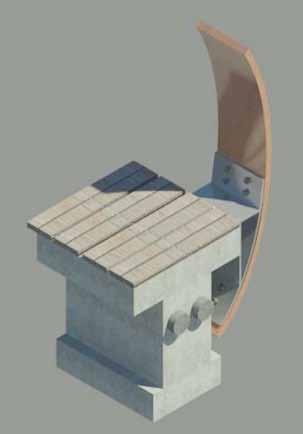
The full class of students were surveyed on completion of the module. 18 students were surveyed in total.
All students agreed that a computational understanding is either very important (82%) or important (18%) to their career ambitions. Furthermore all agreed that knowledge of BIM was necessary (53% very important, 47% important) in their future careers.
With regard to their education 68% said that their education prior to this semester didn’t prepare them for jobs in the construction industry, due to a limited computational education. Subsequent to this semester 70% conclude that they now have a sufficient computational education to prepare them for their careers. However, 30% propose that there is still more that can be done to enhance their computational education before they feel confident for industry.
A total of 10 students performed both the bridge design project module and the building module. These students were surveyed on which they thought was the more beneficial of these modules from a BIM educational point of view.
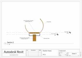
90% of students agreed that the building project gave them a better understanding of BIM and its functionality. However, the class were equally split when asked which project enabled better visualisation at the early design phases.

All students agreed that that the building project gave them a better understanding of the power of BIM for evaluation and analysis. BIM has well designed interoperable analysis packages for building performance analysis. In contrast even the structural analysis programs are complicated when importing simple horizontal and vertical bridge elements.
Similarly all students stated that BIM enabled better comparison of different design options for the building project than for the bridge project. This is not surprising given that simple building designs can be generated more simply using BIM. In contrast the form of the bridge geometry is more complex and bespoke.
70% of students said that they found BIM software limited in its design range due to its set of standardised components, with 60% of students stating that this effected their building design intent. Not surprisingly all students said that their bridge design was limited by the range of standardised components available. This was expected when the project was initiated. The aim was to have students develop components beyond the available families. Given this, 80% of students agreed that “using BIM for the bridge design project allowed me freedom to explore bespoke design beyond the building design process”.
Reasons for these survey results are proposed in the subsequent discussion section.
Introducing BIM as part of project-based modules enabled BIM learning via an education focused on engineering design principles, rather than the simple learning of a software tool without the context of a design problem.
This method of BIM education allowed for a thorough investigation of the multi-faceted capabilities of BIM by students to achieve their design goals and to evaluate their design decisions
It is acknowledged that some students designs were limited by the restraints of BIM software, particularly its propensity for recti-linear form. However, many other students sought work arounds and pushed the limits of BIM to achieve unrestrained designs.
Challenging students to use BIM, generally meant for building design, as the modelling platform for bridge design forced them out of the BIM comfort zone of predefined libraries of components and structural elements.
However, in review this strategy had mixed success. Students did explore the drawing capabilities of BIM
more than in the building design project. However, because of the drawing challenges faced many students focused their efforts solely on producing a visually realistic representation of the bridge. Therefore they used BIM simply as a visualisation tool and did not explore its analysis capabilities nor its quantity takeoff or scheduling potential.
Also many students found the process of drawing of bespoke components to be frustrating and this effected the general enthusiasm for the design project.
However, in general BIM may be viewed as an appropriate tool for engineering design investigation. During the design projects students were counseled to undertake an iterative design process involving; problem clarification via assessment of user and context, concept development, precedent investigation, design development and importantly, constant re-evaluation. BIM did not hinder this design process.
Guiding the students in this process with BIM allowed them incorporate all elements of the presented design problem in a holistic approach that met the requirements of user, program, structure and context. The multi-dimensional modelling and analysis nature of BIM emphasised problem based learning, as students had to encounter and resolve these different demands. Students produced innovative solutions in their designs when they observed opposed design decisions. Design contradictions were viewed as challenges, analysed and reiterated rather than ignored.
It is proposed that this practice enables students prepare positively for engineering and real world problems that “rarely present themselves as well formed structures but rather as indeterminate, untidy situations” [10] Design projects developed using CAD drawing programs or non-parameteric 3D modelling software would not produce the same benefit.
Introducing BIM in the 4th year of a 5 year engineering education might seem a belated and superficial effort. However, it is postulated here that the student should learn about mullions and transoms, for example, not as lost elements grouped in “families” in a software program but as real and detailed elements, that are represented in a simplified form in BIM software.
Introducing BIM earlier in the engineering education could create a situation where the student would not recognise aspects or details of construction that BIM cannot or does not achieve (e.g. panel joints, gaskets, sealants etc.). These aspects should be taught in the
classroom so that the student can understand and sketch detail before adopting with disregard a representation of the same.
The primary conclusions from the introduction of BIM into the education of 4th year Civil, Structural and Environmental Engineering students are:
• Civil engineering students responded well to BIM and learned it without difficulty.
• The design projects proved a good platform from which to acquire BIM skills
• The bridge project proved valuable for learning the fundamental drawing functionality of BIM.
• However, the added difficulty induced by the ardous modelling task, limited the students capability to explore the many layers of BIM.
The higher education authority has called for the development of “core skills such as quantitative reasoning, critical thinking, communication skills, team-working skills and the effective use of information technology” [11]. It is proposed that the designed modules, described here, have achieved these objectives.
It is further proposed that the teaching solution employed involving: (1) initial theory discourse aligned with (2) active project based learning while emphasising (3) design thinking methodologies for practical creative resolution of problems proved a successful one. BIM was very suitable as the output platform for this education process.
[1] R. O. Buchal, “Incorporating Solid Modeling and Team-Based Design into Freshman Engineering Graphics.,” Eng. Des. Graph. J., vol. 65, no. 1, pp. 19–29, 2001.
[2] R. Sacks and R. Barak, “Teaching Building Information Modeling as an Integral Part of Freshman Year Civil Engineering Education,” J. Prof. Issues Eng. Educ. Pr., vol. 136, no. 1, pp. 30–38, Jan. 2010.
[3] M. Prince, “Does Active Learning Work? A Review of the Research,” J. Eng. Educ., vol. 93, no. 3, pp. 223–231, 2004.
[4] C. Meyers and T. B. Jones, Promoting Active Learning. Strategies for the C ollege Classroom. Jossey-Bass Inc., Publishers, 350 Sansome Street, San Francisco, CA 94104
($24.95)., 1993.
[5] “Engineers Ireland - Design Thinking.” [Online]. Available: http://www.engineersireland.ie/cpdtraining/cpd-training/trainingcalendar/2013/february/design-thinkingtaking-innovation-to-a-higher.aspx. [Accessed: 26-Jun-2013].
[6] A. Renkl, R. K. Atkinson, U. H. Maier, and R. Staley, “From Example Study to Problem Solving: Smooth Transitions Help Learning.,” J. Exp. Educ., vol. 70, no. 4, pp. 293–315, 2002.
[7] J. Lovell, Building Envelopes: An Integrated Approach. Princeton Architectural Press, 2010.
[8] P. M. Leonardi, M. H. Jackson, and A. Diwan, “18The Enactment-Externalization Dialectic: Rationalization and the Persistence of Counterproductive Technology Design Practices in Student Engineering,” Acad. Manage. J., vol. 52, no. 2, pp. 400–420, Apr. 2009.
[9] B. Becerik-Gerber and K. Kensek, “Building Information Modeling in Architecture, Engineering, and Construction: Emerging Research Directions and Trends,” J. Prof. Issues Eng. Educ. Pr., vol. 136, no. 3, pp. 139–147, 2010.
[10] D. A. Schon, Educating the Reflective Practitioner: Toward a New Design for Teaching and Learning in the Professions , 1st ed. Jossey-Bass, 1990.
[11] S. Maria, “National Strategy for Higher Education to 2030 Implementation Oversight Group.” [Online]. Available: http://www.education.ie/en/TheDepartment/Bodies-andCommittees/National-Strategy-for-HigherEducation-to-2030-ImplementationOversight-Group.html. [Accessed: 27-Jun2013].
We would like to thank the Senior Sohpister class of 2012/2013 for their enthusiasm and hard work. The authors wish to express their pleasure of having the opportunity to teach you.
Dublin Institute of Technology,
E-mail: 1 michael.mcdonald@dit.ie 2 stephen.donohoe@dit.ie
Abstract The main objective of this paper is to evaluate how Building Information Modelling (BIM) is being implemented and embraced within Higher Education. The authors intend to examine the current delivery and aspirations of the sector.
As the Irish economy faces several more years of austerity, every opportunity must be seized to make design more efficient in Architecture, Engineering and Construction. Higher Educational Institutes must respond to ensure that graduates have the skill set to support this . This paper will examine how these institutions need to migrate away from the traditional iterative design approach/process to a more collaborative holistic approach using BIM.
This will involve a series of semi structured inte rviews of key members within educational organisations, such as Trinity College Dublin (TCD), University College Dublin (UCD) and National University of Ireland, Maynooth (NUIM). The researchers’ organisation has to date set up a new multidisciplinary school which will be viewed as part of this paper. Should there be multidisciplinary schools in all organisations?
At an International level, BIM has become a critical tool for efficient and cost effective modern design. The UK is embracing this change and has mandated the use of BIM through the "Government Construction Strategy”. Ireland’s educational Institutions need to embrace, what some might say is a paradigm shift towards BIM. This paper will identify what barriers currently exist which will prevent Ireland embracing this holistic shift head on.
Keywords . BIM education, multidisciplinary design solutions, curriculum
At an international level, BIM has become a critical tool for efficient and cost effective modern design. The UK is currently embracing this change and has mandated the use of BIM through the "Government Construction Strategy”.
“The pursuit of quality is a journey rather than a destination “[1]
In fact, the area of design, its methods and techniques has had quite a journey to reach the era of BIM. In reality, BIM technologies have been available in some form for the last two decades or so. Unfortunately, in previous years BIM had been perceived by some people within industry as a little too radical for the times [2].However, with today’s impressive digital age BIM has arrived at centre stage.
The potentially imminent shift from traditional design techniques to the concept of BIM creates both challenges and opportunities for higher educational institutions. This new collaborative and integrated design approach offers many new benefits to students, which numerous undergraduate and postgraduate programmes have begun to explore. This paper intends to examine some of the major challenges and opportunities that BIM presents within the educational environment.
The HEA contends that higher education landscape in Ireland must improve quality through centres of excellence [3]. This will offer opportunities for institutions to be beco me experts in specific disciplines, for example BIM. This can be offered at both undergraduate and postgraduate level, which will allow students develop skills to enable them to play a strong part on the world
stage [2]. To ensure a high standard of delivery, this will require qualified staff, staff that are motivated and for staff to be allowed to pursue opportunities and conduct research in specific areas relating to BIM Like all organisations, a clear career path should be established for staff to develop their talents through scholarly activates. Team leaders would be required to ensure relevant delivery of modules. Moreover, students must have access to teaching that is kept up to date and relevant through scholarship, research and professional development [2]
The National Strategy for Higher Education recommends the development of a Technological University for the Institutes of Technology in Dublin. This new age university will prepare students for real life complex professional roles in a changing worldwide labour market. This type of university has the unique opportunity to allow students advance their knowledge through the use of industry specific software, including BIM.
The National Strategy acknowledges that one of the key strengths of our higher education system has been, and should remain, institutional autonomy [3].
Ireland’s past vision and innovation to invest in education as a whole, has played a major role in supplying the cohort of skilled graduates that helped the significant increase in indigenous engineering, manufacturing and export growth which was achieved towards the end of the twentieth century. However, even with the significant overall increases in investment in higher education, per capita expenditure remained modest by international standards throughout the period of growth, and has significantly decreased since 2009. This has unfortunately, and to the disadvantage of students, lead to a widening of the staff to student ratio [3]. This situation makes the delivery of new software somewhat more challenging whilst trying to maintain high standards within the educational environment. A comparison of the funding of higher education between England and Ireland reveals that funding per student in Ireland is between 19% and 29% lower than funding per student in England [4].
Hietanen and Drogemuller contend that, BIM can be first introduced into a module and then into other disciplines, either as a core part of a programme or as a separate standalone element [5]. It is, however, essential that students are still provided with an introduction to basic drawing fundamentals and drawing software. With this grounding they can then develop their BIM and cross disciplinary skills, thus, enabling the creation of holistic comprehensive design. The majority of BIM software requires the user/designer to interact with a multitude of
disciplines at a critical early design stage. This process must be fostered within the learning environment to encourage and promote collaboration and communication. With a changing labour market, in relation to a modern design process, this will be a key skill requir ed from graduates. Students working alone within their discipline will be able to develop their BIM skills, but only to a certain point. There is a definite need for a multidisciplinary approach. The students must be allowed to engage in Problem Based Lear ning (PBL) which requires engineering resolution which could be as basic as co-ordination of services. In fact, so me of the institutions surveyed highlighted that there was an educational shift back to PBL.
The 21st century engineer and architect must be able to deal with a rapid pace of technological change, a highly interconnected world, and complex problems that require multidisciplinary solutions [6]. Moreover, the higher educational student experience should equip graduates with essential generic found ation skills as adaptive, creative rounded thinkers – in addition to a comprehensive understanding of their relevant discipline [2].
Will the BIM approach become a completely separate discipline? The NBS Report (a trading name of Royal Institute of British Architects (RIBA) Enterprises LTD) contends that the historic rules of engagement between educational institutions and professional accreditation bodies tend to prefer separation and division between disciplines, thus, avoiding untested collaborative education [11]. This raises the question, can collaborative education be taught without actually being experienced in a real life industrial environment?
The Government (UK) will require fully collaborative 3D BIM (with all project and asset information, documentation and data being electronic) as a minimum by 2016 [12].
With the UK enforcing legislation relating to BIM, Ireland will inevitably follow suit. Moreover, with the European Union’s directives and regulations pertaining to higher levels of energy performance in buildings, BIM will play a pivotal role in reaching these targets. In fact, a Client Mobilisation and Implementation Group have been developed to drive the adoption of BIM across the UK Government. Whilst in Ireland, the main driver behind BIM is the Construction IT Alliance, whose goal is to harness the potential of information and communication technologies for the Irish
construction sector.
When discussing BIM and the different levels within this concept, the following dimensions (D’s) (or similar) are generally referred to:
1D - Client needs & requirements.
2D – Draughting, planning & specification.
3D – Modelling
4D – Logistics & contracts.
5D - Quantifying.
6D - Project management, construction & commissioning.
7D - Buildings life cycle.
8D - Decommissioning.
Many different disciplines of engineering worldwide are working through the challenges presented by the adoption of BIM. There are enormous roadblocks and challenges both physical and in mind-set to be faced. Several organisations throughout industry are facing these challenges with enthusiasm. Thus, third level institutions also need to adapt and move away from traditional isolated and un-collaborative methods to more interdisciplinary methods.
To date there has there has been a BI M strategy set up in the authors’ own institution, Dublin Institute of Technology, with some of the objectives of this strategy outlined below;
1. To ensure our graduates have the required skills, competences, knowledge and understanding to meet the needs and expectations of industry;
2. To place College at forefront of BIM education in Ireland;
3. To unlock the potential within the Co llege to provide real interdisciplinary education;
4. To provide education in BIM and related technologies at appropriate stages and at the appropriate NFQ level;
5. Meet the needs and expectations of industry.
6. BIM educational process, focusing on BIM as a whole business and interdisc iplinary concept along with the adopted world standards.
As part of this paper's research all institutions involved were asked the question: Does your institution / school have a BIM strategy? The summary response revealed that two of the institutions surveyed currently have a BIM strategy in place, whilst the other institutions do not have one in place. This then lead to the next question which asked the survey participants; What were the most significant barriers that existed to prevent the implementation of BIM within said institution? The responses varied from each participant, quoting, "lack of expertise in the area", "lack of interest amongst staff members to up-skill in this new area", "problems associated with timetabling different disciplines to be in the same space together at the same time"
Time paints a clear picture, as outlined in the National BIM report [7] . Based on the figures below it would seem that educational institutions must urgently embrace the concept of BIM.
This section will detail the issues regarding the delivery of BIM courses. To successfully deliver a BIM related course, an institution must have a modern IT laboratory facility. This would require a dedicated server to accommodate the large storage capacity which is required for multiple BIM users. Technical Officers would also be required to provide support for lab PCs. There are also issues with software licenses that would need to be addressed.
The evaluation of BIM skills and students progress should involve a combination of formative and summative assessment. This allows students to develop a BIM portfolio which would include academic technical papers, and a series of project – based digital models. Essentially, there are three skill levels involved in BIM introductory, intermediary and advanced [8]. There are potentially three barriers to the delivery of BIM in the educational environment [9].Firstly, difficulties in learning BIM, this relates to existing professionals from industry which may be retraining or up -skilling. Presently, there are a large number of unemployed professionals competing for the same employment posts, therefore, graduates need to increase their knowledge and expand their skill set to prepare for re-entry into the labour market. Secondly, difficulties in using BIM software, again relates to existing professionals, as younger students tend to find it easier to adapt to modern technology / software.
Finally, a misunderstanding of the holistic BIM process, which ma y be the most problematic barrier of all. In fact, problems related to the misunderstanding BIM concepts are the most important hurdle to overcome.
Barison and Santos contend that, institutions wishing to implement BIM are likely to face several problems, the greatest of them being the interaction between different disciplines [8]. There needs to be major changes in teaching methods to shape the future of industry. This will be a slow process but can be achieved by the implementation of educational stepping
stones which will allow young engineers steer society towards a sustainable future. Educational tools, alongside an overall awareness of BIM, needs to be embedded into young engineers. The reason being, it will form a significant part of their future roles.
As industry shifts towards adopting Integrated Project Delivery (IPD), our third level educational institutions must adopt a more collaborative approach to teaching. To future proof the higher education sector there must be an outward facing system which interacts, not only between disciplines, schools and other institutions but with the wider community. This will ensure an inward and outwards flow of knowledge, staff, students and ideas between institutions and its external community [2]
The Authors felt the need to highlight that as part of this paper, less than half the institutions approached responded to the survey (6 out of 14) Thus, there is potential for future research relating to the educational sector and BIM. It would have been envisaged that this number would have been greater, but due to time constraints and the period of the academic calendar, it was tougher than expected to obtain responses. It should also be noted that this is only a small sample of the higher educational institutions of Ireland
The survey consisted of twenty short questions. The majority of these questions were closed questions requiring ‘yes’ or ‘no ’. A minority of questions allowed for comments and opinions. Some of the surveys were completed as face-to-face meetings while others were completed via an online survey. The authors will try and provide a qualitative overview of the responses relating to the more important questions.
As previously mentioned, the survey consisted of visits to the various institutions, whist the remainders were carried out via online survey.
As outlined below in Fig1 it can be seen that 33% of the participants surveyed currently have a BIM strategy in place.
All of institutions surveyed are still using traditional draughting tools such as AutoCAD and 83% of the surveys indicated that they still felt that traditional drawing packages such as AutoCAD have a place in the educational system and within industry (See Fig 2 below).


One of the questions encouraged t he participants to comment on their personal views in relation to their understanding of the benefits of BIM Table 2 below illustrates a summary of these answers
Throughout the various institutions there are several different software packages being used such as; Autodesk – Revit , Architecture, Structure and MEP, Energy plus, Navisworks, Cost X, Synchro, Ecotect Analysis, IES, Soildworks, CFD work, Google sketch-up, Optics and Matlab. In essence these different packages make up a lot of the different software types currently being used as part of the BIM process. The concept of BIM was not something that was common kno wledge throughout all institutions surveyed In fact, only 33% of the participants surveyed stated that it was commonly known throughout their institution and this cohort also had a BIM strategy, as outlined in Fig1.
1 Better data storage
2 A lot more information available
3 Interaction/collaboration with a design team
4 Cost saving
5 Interaction/collaboration with a design team
6 Better design, Interaction/collaboration with a design team, Higher building energy performance, having regard for the whole BIM process – benefits too numerous to list.
The same percentage figures applied to the amount of staff training that had been undertaken at the various institutions where 33% have had specific training in the area of BIM and 66% have not had any training.
Eighty - three percent (83 %) of participants felt that employers now expect graduates to have certain BIM competencies. Meanwhile, 17% felt that as long as the graduates have the fundamentals of their specific discipline, that the employers could train the individuals further as required.
All participants were in favour of a multidisciplinary approach to student learning, but had some underlying conditions. Some were of the opinion that a multidisciplinary approach would work better at postgraduate level rather than at undergraduate level; the reason being, that students were more mature and generally more motivated with in their discipline. Having a multidisciplinary approach would be a good experience for the students, provided it does not come at the expense of something else, particularly the fundamentals associated with each sub-discipline.
It is evident from this research paper that the new design process of BIM and the challenges faced whilst integrating in to the educational system will be somewhat more complex than just simply adding a new BIM module to existing programmes.
Unfortunately, some people from the educational sector and industry still believe that BIM is a specialised activity and that it is too major a leap to take forward at this early stage [11].
This mind set can present problems with the implementation of new design methods / tools. Ireland is already behind the UK in terms of integration of BIM and if this change is not embraced the gap will widen further leaving our economy exposed.
Of all the participants surveyed , 67% were aware of the CITA BIM group and the main drivers of BIM in Ireland at present.

Barison and Santos argue that, BIM has the potential to be an intrinsic part of the whole engineering sector. Moreover, they go on to detail a teaching strategy / structure; wherein fundamental principles of BIM should be taught first followed by BIM concepts, such as teamwork and complexity [10].
This could be implemented over a number of years as the students develop and advance their skills.
This paper set out to examine the potential educational barriers which may delay this paradigm shift towards BIM. With no policy or legislative structure in place for BIM, this presents future research opportunities for collaboration between academia, industry and relevant government bodies.
In the next few years, as the use of BIM increases throughout industry, the demand for highly skilled graduates will follow suit. It was also the opinion of the surveyed participants that the use of BIM in the construction sector would most definitely increase manifold. Thus, it is the responsibility of third level institutions to take action and correctly adapt programmes to meet the future needs of the labour market, both nationally and internationally. This paper highlights several significant challenges with the implementation of BIM. It also presents an opportunity to further examine the implementation of BIM throughout industry. A larger cohort could be surveyed which would allow a paper to be developed concentrating specifically on industry and a range of businesses.
What will the role of an engineer look like by 2050? Surely it would be unrecognisable from today? The BIM revolution is undoubtedly here to stay and is completely changing the way design and maintenance takes place in the built environment
[1] Dublin Institute of Technology – Handbook for Academic Enhancement 2010
[Accessed 20/4/13]
https://www.dit.ie/media/academicregistrar/AQE H_june10_collated.pdf
[2] Higher Education Authority (HEA) 2011a, National Strategy for Higher Education to 2030 [Accessed 22/5/13]
http://www.hea.ie/files/files/DES_Higher_Ed_Su mmary.pdf
[3] HEA 2012, Towards a Future - Higher Education Landscape [Accessed 25/1/13]
http://www.hea.ie/files/TowardsaFutureHigherEd ucationLandscape.pdf
[4] HEA 2011, Sustainability Study - Aligning Participation, Quality and Funding in Irish Higher Education [Accessed 28/1/13]
http://www.hea.ie/files/files/file/News/Sustainabil ityReport.pdf
[5] Hietanen, J. and Drogemuller, R., 2008. Approaches to University Level BIM Education. In: IABSE Conference, 2008, Helsinki, Finland.
[6] Becerik-Gerber, B. and Kensek, K. (2010). ”Building Information Modeling in Architecture, Engineering, and Construction: Emerging Research Directions and Trends.” J. Prof. Issues Eng. Educ. Pract., 136(3), 139–147.
[7] NBS 2013, National BIM Report [Accessed 21/5/13]
http://www.thenbs.com/pdfs/NBSNationlBIMReport2013-single.pdf
[8] Barison, Maria Bernardete, and Eduardo Toledo Santos. 2010, BIM teaching strategies: an overview of the current approaches
http://www.engineering.nottingham.ac.uk/icccbe/ proceedings/pdf/pf289.pdf
[9] Kymmell, W., 2008. Building Information Modeling – Planning and Managing Construction Projects with 4D CAD and Simulations. New York: McGraw Hill, 2008.
[10] Barison, Maria Bernardete, and Eduardo Toledo Santos. "Review and Analysis of Current Strategies for Planning a BIM Curriculum." Proc., CIB W78 2010 27th International Conference. 2010.
[11] NBS 2011, Building Information Modelling Report March 2011
[Accessed 20/5/13]
http://www.cadtrainingonline.com/bimResearchR eport_2011-03.pdf
[12] Cabinet Office 2011 (UK), Government Construction Strategy
[Accessed 21/5/13]
https://www.gov.uk/government/uploads/system/u ploads/attachment_data/file/61152/GovernmentConstruction-Strategy_0.pdf
Scott Sutherland School of Architecture and Built Environment
Robert Gordon University, Aberdeen, UK
E-mail: h.salman@rgu.ac.uk
Abstract This paper presents a challenging stand for architectural technology (AT) students, and roles. What roles are AT graduates going to play before and after the 2016 Building Information Modelling (BIM) mandate and how academia is preparing them for such roles. All these questions and others have been debated since the mandate, speculation more than any other tangible knowledge or experience is the basis for most changes to the AT curriculum. AT student expectations have been explored and the different opportunities that a graduate might have, in the light of the suggested roles. A survey was designed and emailed to third year students in the second semester of their study. The purpose was to understand students perception on BIM within the context of professional practice (s) this included both; work placement and Simulated Professional Practice. The results suggest that BIM as a practice in context still lacking, however AT graduates feel confident for the mandate. But to overcome the current transitional stage academia needs both; context ual teaching and training of BIM, and stronger ties with the industry. Achieving that would provide well-trained and confident AT graduates to take up the transitional change competently and innovatively in AEC practices .
Keywords Architectural Technology skills, BIM, Final Year Education, Placement, Professional context, Change.
With the government Building Information Modelling (BIM) 2016 mandate, the construction industry is faced with changes in practices, processes and roles. Consequently, Architectural Technology (AT) as a profession has the ability to gain versatile opportunities to complement the gap between the architect and other construction parties,but this can only be accomplished if AT graduates have the technical skills to support both, knowledge of building design and BIM workflow.
The BIM strategy has added another technological responsibility for AT - to bridge the different attitudes of interdisciplinarity. This responsibility comes mainly from Information Technology (IT) and its new ways of doing things. The current shortage of trained BIM personnel is a barrier to BIM implementation.
This study considers the effect of work placement on contextual learning possibilities for full-time curriculum of Architectural Technology
education. It discusses the approaches adopted in the Scott Sutherland School of Architecture and Built Environment at Robert Gordon University, which we believe will be of interest to colleagues and educators in other schools who are concerned with a lack of opportunity to undertake practical training allied to the built environment.
The study employs a questionnaire survey to look at the effect of undertaking work placement and attendance at a professional practice studio on the participants’ skills development. This survey examines the current position with regard to the balance between education and work in practice. A detailed account is provided with a focus on professional studies, where some issues and opportunities were highlighted for improve ment.
Encouraging the development of Information Technology (IT) skills is a key part of the UK Government’s strategy to improve the construction industry productivity and performance. Recently the
Government’s Construction Strategy complemented this with its mandate for 'fully collaborative 3D BIM as a minimum by 2016' , and the need for efficiency and industry reform to realise a 'cost reduction of 20% during the term of the current parliament' (National BIM Report, 2012 p.04). This has already encouraged many firms to revise their “technology assessment and training programmes, to make sure that they can measure the skills of key personal ” or new graduates.
At the same time, it is necessary to understand the changing needs of the industry and these must be communicated to be able to develop governance that supports UK students to acquire the right skills in the field of Architecture Technology and Built Environment. This can be achieved through a centrally co-ordinated collaborative approach to monitor skills development of final year architecture technology students, and architecture design students.
Therefore, an investigation into the influence of placement from an industrial context on students’ skills is required. Bearing in mind that until now there has been no consensus on how best to address this aspect of students’ development (Salman, 2011), this research focuses on the practical skills of students in both AutoCAD (CAD) and Revit (BIM). Other studies focused on skills that are more generic and their impact on students’ professional capacity. Taking into consideration the potential benefits for architectural technology programmes, this research will help set the agenda for professional training and BIM integration – areas that have to be set properly to maintain our educational role and impact for the 2016 BIM mandate.
The focus of this study is on one aspect of employability - that is graduate’s confidence in using BIM (3D CAAD based design processes) within a placement as opposed to University (Salman, 2011). How would placement change students’ engagement in learning and using CAAD (2D and 3D) while the context is different? How this might enhance their confidence and employability after graduation? Remarkably, this is an under-researched area and requires more efforts by scholars to understand how teaching programmes can bridge the technical/professional aspects of students’ development: that is, how undergraduates are using BIM principles and 3D skills rather than learning new skills and other attributes through the higher education process. This will have a positive impact on student’s professional preparation.
One aspect of our teaching is the terminology that we use to express concepts and relations.
Adopting new technologies brings new terminology, when BIM is mentioned the wording used implies that all parties are present in one way or another.
“It makes designing fun again. We are not drawing lines, we are building a building ” (Downs, 2009).
Active and experiential learning of BIM have changed terminology in two ways. The language has become more active in the sense that it carries with it collaborative meanings and shared values. Table 1 shows some of the differences between the terms of yesterday (then) and tomorrow (now or tomorrow).
They We are..
2D drafting 3D, 4D, nD
Sketching ideas
Building ideas
Print Digital
CAD skills
Modelling
Drawing Prototype
While they differ, they share similar aims and qualities. The adapted terms aim at placing emphasis on the exploration of 3D qualities and information extraction whilst also emphasising information transmission in an integrated approach.
When BIM is mentioned CAD also mentioned, even if implicitly, and the question of whether BIM is CAD or CAD is BIM comes to the forefront. Based on teaching BIM, Eastman et al. (2008) recognised clearly that “students are able to grasp the concepts and become productive using BIM tools more quickly than they were with CAD tools”. BIM appears fairly intuitive to students, and it more closely resembles their perception of the world .” Because BIM requires different ways of thinking about how to develop designs and manage construction of buildings, the industry sought to retrain those employees who are more familiar with CAAD (Eastman, et al., 2008). This training needs to balance old ways of thinking (primarily 2Dbased) and working habits with different pro cesses and work flow. New graduates, who are influenced by their familiarity with BIM and use it for a full
range of undergraduate projects, are likely to have a profound effect on the way that companies will deploy BIM.
the common perspective of why these systems are important in design schools and design teaching.
AEC industry requirements change with time, e.g. the BIM 2016 mandate, and all careers are subject to such changes (Soltani -Tafreshi, Twigg, and Dickens, 2009). It is imperative that students are able to handle the uncertainty that comes with such changes. Academia tries to highlight potential roles and the accompanied changes as these requirements are not always aligned with the curriculum.
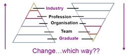
In the literature, the term CAAD is treated as an inclusive term of all CAAD systems that may be used for the architectural design process (Salman, 2011). However, it is not inclusive or generic from students’ point of view. In Salman’s (2011) study, all participants agreed that when CAAD is mentioned they associate it with the most used CAAD package AutoCAD (no mention of ArchiCAD, although it has been taught in parallel, and it is a CAD compound term). Briefly, the study suggests three things: 1defining the term CAD or CAAD as a meaning was based on a practical context in relation to the way it was used by students during their university education; 2 - introducing CAAD in a detached manner from its historical evolvement and philosophies, and 3 - to reflect on the differences between different CAAD software programs such as AutoCAD and SketchUp, which are totally different in the way they work.
BIM implementation does not mean employing another CAAD software program, or a particular software program, even if t hat software program is 3D based. Implementing BIM involves both technology and process, as the existing processes will evolve with the implementation of BIM technology (Deutsch, 2011).
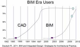
Most schools consider the integration of computer literacy and CAAD as one concept (Mark, Martens and Oxman, 2003), which involves the teaching of two types of computer systems: social and professional. In recent years, Garcia et al. (2007) challenged professional (commercial) systems by proposing an educational system that has the same aspects of AutoCAD commercial software, but with an easier learning curve. The results showed that students preferred to learn and use AutoCAD even though it is more difficult than the new system. This preference was based on two reasons: CAAD’s advanced technical aspects, and its role in their future career (Garcia, et al., 2007). This also reflects
With a mandate from the UK government, BIM adoption is inevitable. However, its implementation may manifest in two opposite directions suggesting that change needs a wider base; this wider base may be presented by new graduates coming BIM ready to industry, or by industry technological reformation. The most likely is that graduates will take the lead to bridge the identified gap between industry and academia, between technology and multidisciplinary teams.
The term design workspace refers to the tools that are available to designers in a shared workspace; either studio or practice, such as CAAD software programs and paper-based, and the designers’ interpersonal communication channels (Maziloglou, Scrivener and Clark, 1996). In the workspace, one can observe both interpersonal interactions between designers and other construction specialists, and their interaction with the various workspace tools and media. These two interactions are responsible for giving the design workspace its richness and complexity. The flow of work may change to accommodate a new technology or approach to design processes. Workflow has changed in the industry to suggest new experiences and problems. However, collaboration and cooperation are the most appraised by employers and professional practices.
The interaction between students and tools and their ability to be critical of the used tool also depends on the level of skill in using this tool and, to a certain extent, how confident they feel interacting with a tool in the academic context of the studio. If the skill is available, then interaction will take place
and as a result, the student’s ability to be critical will mature.
Universities in the UK promote the merits of vocational degree programmes that combine academic rigour with periods of placement within industry. At Scott Sutherland School third year AT students have to select one option from the following professional contexts: Industrial Placement, Simulated Professional Practice, or Exchange Programme.
BIM means different things to differen t professionals, working with BIM means a profession has more specific roles that an AT, CAD manager or IT coordinator. Some of the research on BIM comes from a particular discipline or professional perspective. Specific literature has been written to help professionals and graduates to understand the benefits of BIM and the changes in roles. This change can be categorised under new emergent professions as outlined below (Oxman, 2008; Salman, 2011; Simpson, 2012):
• The Technology Manager: An AT who is responsible for setting up information, communication and modelling strategies for the whole project team (s), from start to operation.
• The Modeller: An AT who is responsible for creating geometry based models, and any detailed components required for the B IM model.
• The Toolmaker: An AT who is responsible for tailoring tools, apps and interfaces to allow exchange of ideas, information and data between different project team members and software programs.
• The Researcher: Anyone who wants to bridge the gap between theory and practice to speed up implementation and solve problems.
The interaction between research, practice and education is important in producing and revealing necessary knowledge. Through this interaction, the applicability of CAAD from one context to another can be observed and applied through design practices. Thus, the investigative (physical) setting is a significant factor in the overall research approach to design processes, which affect the research methods used. For example, work placement as a setting provides a reliable indication of the applicability of student’s transferable skills.
This study methodology aims to monitor the effects of professional context (under si mulated or real conditions) on undergraduates' skill development, which also supports the “process”
point of view of research methodology as an explorative methodology. Consequently, the current research involves a questionnaire survey to monitor students’ development during their second semester professional practice.
The research started with a literature review focusing mainly on the following ke ywords; work placement and skills acquisition, employability and attributes, professional co ntext and BIM adaption. The search included both literature on general employment skills and literature specific to architecture technology and architecture disciplines. The goal of the literature review was to find out the main skills of the discipline and develop a questionnaire that is explorative in nature. The questionnaire focuses on how undergraduates comprehend their generic skills, specifically CAAD skills development, through work placement and simulated professional practices, and how their CAAD/ Revit skills were perceived by the employer.
The questionnaire survey was exploratory in nature, but also evaluative, which was critical in two respects. Firstly, it describes the contemporary student from the student’s perspective by reflecting on their experiences and the application of CAAD and BIM (if any), in order to support the study with contextual propositions. In addition, it further informs what needs to be changed or modified in subsequent year(s) of study.
Data from the targeted sample was collected for the following research objectives:
To describe the targeted sample in terms of their skills, knowledge and contextual learning in the professio nal context, and
To know how students measure their learning preferences and needs.
A questionnaire survey was designed and circulated using an online tool (dotsurvey.com) to gain an understanding of the professional context within which students operate and interact. This study was able to clarify the effects (if any) of their professional practices on skills acquirement and employability expectations and helped to gain understanding of how context would affect CAAD’s future integration in the architectural technology curriculum.
The targeted sample consisted mainly of third year students who have been studying Architecture Technology at the Scott Sutherland School of
Architecture and Built Environment for at least two years, with an average of one -year industry experience (taking a placement).
Twenty-five responses (representing a 50% sample of the cohort 2012-2013) were received. T he questionnaire took approximately 3 minutes to complete. Results are presented in the same sequence as the main survey.
Descriptive analysis was carried out to provide a general overview of the sample to be presented in percentages. Survey responses were analysed using an Excel spreadsheet. Survey responses were analysed using the MS Excel package by performing descriptive statistics, and presented in percentages.
In response to what the participating students (third year) had to do in their semester-two studies, work placement and professional practice simulation were cited equally, with a percentage of 43%. This is shown in Figure 3. Only 14% cited none of the two options.
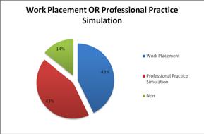
It is obvious that third year students were consistent in assessing their design skill and extremely inconsistent in assessing their CAAD skill by scoring various levels of CAAD experience within the same studying stage. This should be taken into consideration when designing any CAAD related modules. Normally, students at earlie r stages of education have various levels of skill, something that is less likely to be noticed when they are in the final stages of their education. Therefore, access to various levels of CAAD tutorials is essential for AT students.
Figure 5 shows the differences between the main two contexts in terms of CAAD use in relation to work placement and professional simulation. In the workplace context, more than half of the students (53%) tend to use CAAD for 2D drawings with a lower percentage (29%) of them using it for simple 3D drawings (without rendering). Only 18% of them use it for 3D modelling (with rendering).
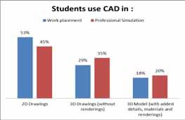
Students’ self-assessment of their design skills (architectural design, and CAAD) was highlighted in the following manner. Students’ skill “selfassessment” was measured on a five–level scale from poor (1) to excellent (5). The results are shown in Figure 6. The results showed that students ranked their design skills as follows: architectural design skills mean score is good (mean score of 3.4 out of a possible 5), and CAAD skills mean score is good (3.8); slightly higher compared to their design skill.

The chart in Figure 4 provides a visual indication of the students’ self -assessment scores showing the lowest and the highest score.
On the other hand, the results in relation to professional practice showed a different trend, CAAD use in a professional simulation studio. Figure 5 shows that less than half of the participating students tend to use CAAD for 2D drawings with a lower percentage (35%) of them using it for 3D drawings. Only 20% of them use it fo r 3D modelling (detailed and rendered).
In general, the results show that the use of CAAD for 2D drawings is significantly higher than 3D use in the workplace context. The use of CAAD for 3D drawings is significantly higher than 2D use in the professional simulation studio. This could suggest that academia has enhanced the use of 3D within its curriculum compared to industry, and potentially demonstrates how academia might be quicker to adapt BIM practices/principles.
The responses of students to whether knowing that you are skilful in 3D modelling is an important aspect to your work placement are shown in Figure 6. More than half (56%) of the sample found it very important that their employers knew that they were skilful in 3D modelling. Forty four percent of the sample reported that having 3D modelling skills is not important for their employers.
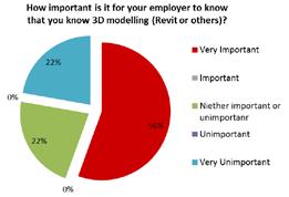
The students were asked if either their place ment or professional simulation have validated the skills and knowledge of their undergraduate studies. The majority (89%) of the sample completely agreed that work placement validated their studies, and 11% neither agreed nor disagreed. This data is shown in Figure 8.
In the context of professional simulation, 40% percent felt that professional simulation practice has validated their knowledge. Fifty percent of students neither agreed nor disagreed with the statement, while 10% of the sample disagreed. These differences suggest that students relate knowledge validation with work placement rather than a professional simulation studio. Students still believe that work placement acts as a real industrial context and as such would validate their skills in a tangible way.
Based on the sample’s background and skills, Figure 7 shows that less than half of them (45%) believe that using 3D modelling in the workplace has influenced their working capability in general, and 44% neither agree nor disagree with the same statement, with 11% disagreeing. This suggests that the sample’s views regarding 3D modelling impact on design related issues and capabilities are divided, although they share the same level of knowledge as they are at the same stage of education.
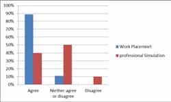
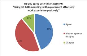
Results also showed that while students recognise the contribution that the course had offered them so far, they still feel that there is a lot to learn from a professional context. The importance of teamwork, being given responsibility, and collaborative learning emerged as the most important factors for effective learning in the two professional contexts under consideration. They also felt that they needed to learn about other principles and relations in their final year taking into consideration integration of the following skills (Figure 9):
All participating students involved in the survey had experienced work placement or professional simulated practice as a formal part of
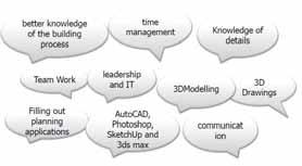
their undergraduate studies. Results showed that while graduates recognised the contribution university had made to their generic skills development, they greatly valued the experience of learning in the workplace during placement and, subsequently, in employment.
Students who were in the workplace were asked if BIM was implemented yet or not. The results show that 22% of them indicated that they had not implemented BIM yet, and a similar percent indicated that their employers were planning it presently. More than half (56% percent) indicated that they have no plans for implementing BIM in the near future. On the other hand, 22% of them indicated that they are planning for implementation at present. Another 22% indicated that they have already implemented BIM, demonstrating that industry is providing students with little opportunity currently to gain full experience and benefits. How industry is going to deal with BIM and how these contextual experiences are conveyed to industry is still unclear as this loop is very weak at present.
Finally, third year students were asked if they feel confident that they have the skills required for the BIM 2016 mandate. Most of them felt that they need practical experience with BIM to feel confident about the mandate. However, 29% felt confident that they already have the skills required for the mandate. Nine percent felt that they needed to learn about the theory and 5% felt that they were not confident in doing so.
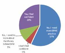
Those students whose employers had implemented BIM were asked whether they had experienced BIM in the workplace context. The majority indicated that they had not. However, a low percentage (12%) had experienced BIM in the work place. This result is very dependent on the answer to the previous question relating to BIM implementation in the construction industry.

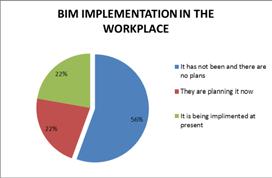
All students involved in the survey had experienced either work Placement or Simulated Professional Practice as a formal part of their third year undergraduate studies. Results showed that while graduates recognised the contribution university had made to their generic and technical skills development, they greatly valued the experience of learning in the workplace during placement and, subsequently, in professional simulated. The importance of teamwork, being given responsibility, and collaborative learning emerged as the most important factors for effective learning in the two contexts under consideration.
BIM awareness should be raised to include the many facets of the emerging roles for AT graduates. The curriculum should be complemented by BIM through integration and contextual learning and teaching projects, which would enhance programs accreditation.
BIM practice is evolving rapidly in the industry; academia should be clear about defining graduates’ role after 2016 to establish the confidence needed to start their career. On the other hand, the industry should push its opportunities by enhancing BIM practices for our graduates and the AEC industry. In light of the 21st Century challenges for higher education, 3D CAAD and BIM principles become much more critical as a knowledge base. The professional context is the most vital medium for BIM learning and knowledge integration. Recent claims emphasised trans-disciplinary knowledge integration into the studio context (Salama, 2008), taking students’ needs as the main criterion because it would be more effective to channel stude nts’ efforts toward their professional needs.
An extended study to emphasise and inform longterm (professional) development should be considered. Therefore, future studies should include how undergraduates’ skills are developed through work placement, and to what capacity, and how their abilities and skills are enhanced or modified through professional work placement.
The author would like to acknowledge contributions by (third year) students in Architectural Technology. Also thanks go to Graeme McRobbie, the school’s Professional Studies Advisor and Placement Coordinator.
[1] CREBERT G., BATES M., BELL B. and PATRICK C., 2004. Developing Generic Skills at University, During Work Placement And In Employment: Graduates’ Perceptions. Higher education research and development , 23(2), 147-165.
[2] DEUTSCH R., 2011. BIM and Integrated Design: Strategies for Architectural Practice, 1st ed.: Wiley.
[3] DOWNS, P., 2009. BIMming with enthusiasm [online]. St. Louis Construction News. Available from: http://www.stlouiscnr.com/features/article/bim ming_with_enthusiasm/ [Accessed 1 February 2013].
[4] EASTMAN, C., P. TEICHOLZ, R. SACKS AND K. LISTON, 2008. BIM Handbook: A guide to building information modeling for owners, managers, designers, engineers and contractors, Wiley.
[5] SALMAN, H., 2011. The Impact of CAAD on Design Methodology and Visual Thinking in Architectural Education . PhD Thesis Robert Gordon University.
[6] NBS, 2012. National BIM Report., London: NBS.
[7] KIVINIEMI, A., 2012. HEA STEM Workshop: BIM Education for AEC professionals. Salford University, SOBE. 9th May.
[8] MORTON D.E., 2012. BIM: A Transformative Technology within the Architectural Curriculum In Schools Of Architecture. In: First UK Academic Conference on BIM, 5 -7 September 2012, Northumbria University.
[9] MASON G., WILLIAMS G, CRANMER S. and GUILE D., 2003. How Much Does Higher Education Enhance the Employability of Graduates?.Higher Education Funding Council for England (HEFCE), Research Report 13/03.
[10] MAZILOGLOU M., SCRIVENER S. and CLARK S.,1996. Representing Design Workspace Activity, in Analysing Design Activity, pp.389-416. Edited by Nigel Cross, Henri Christians, and Kees Dorst, UK: John Wiley and Sons.
[11] SOLTANI-TAFRESHI, F., & TWIGG, D An effective practice in preparing students for workplace. Inspiring the next generation of engineer, Higher Education Academy.
[12] SALAMA, A M. 2008. A Theory for Integrating Knowledge in Architectural Design Education.. Archnet IJAR 2.
Waterford Institute of Technology, Ireland
E-mail: 1kthomas@wit.ie
Abstract This paper focuses on a joint academia-industry BIM partnership in Ireland. The partnership was based on €3 million design and build project that was developed via a tender process in late 2012 using 'traditional' technology (including 2D CAD). The successful tender was led by Clancy Construction and their team gave the tender information to Waterford Institute of Technology for a student BIM project to be completed in the second semester of the 2012/13 academic year (January to May). The students were a mix of Architectural Technology, Construction Management and Quantity Surveying. As part of their scheduled semester modules they developed a BIM model of the proposed building. The industry partners contin ued to develop the 'real’ design and build project in parallel with the student BIM project. At the end of the semester a full presentation by the students of their project was made to the design and build team. The paper reviews the general context of BIM in AEC Education and the associated role of academia-industry partnerships. An overview of both the industry design and build project and the student BIM project is also included and the associated lessons learned are identified. The paper concludes with an overview of the 2013/14 BIM related plans at Waterford Institute of Technology, including the extension to the academia-industry partnership agreement for everyone’s benefit.
Keywords BIM, Industry-Academia partnership, case study, Ireland.
With the increasing adoption of Building Information Modeling (BIM) throughout the global Architecture, Engineering & Construction (AEC) sector, stakeholders in the Irish construction industry are beginning to recognize the potential of this important technology. For academia, this has led to a growing requirement for educational institutions to prepare their students to have a sufficient level of knowledge of BIM. However, one of the main challenges of introducing BIM into the undergraduate curriculum is that historically, AEC professionals have been educated in isolation from one another. In terms of the broader scope of IT in AEC education, Thomas1 discussed the educational challenges of integrating a variety of people, processes and technologies, concluding that “students in different disciplines should be encouraged to mix, undertake group assignments, share digital information and generally appreciate the potential contribution of other disciplines to the AEC industry.” In addition
to these challenges, the general consensus is that there are two issues requiring consideration for the integration of BIM into the educational curriculum; training students in the use of BIM software applications and appreciating the integrative and collaborative potential of BIM between the various AEC stakeholders (Eastman et al2; Barison and Santos3). It is against this backdrop that an industry-academia partnership was formed between Waterford Institute of Technology (WIT) and Clancy Construction led design and build team to learn about BIM.
In January 2013 WIT was approached by the Managing Director of Clancy Construction with a general remit of exploring the potential of BIM within their organization. Initial discussions revealed that whilst Clancy Construction were aware of the increasing importance of BIM throughout the global construction sector, they had little prior knowledge of its specific capabilities from a contractor’s perspective. A project that the company had recently been awarded was identified as a suitable test bed for the potential of BIM. The
Enterprise, Research & Development (ERD) Centre is a €3 million design and build project on the outskirts of Clonmel in County Tipperary. The scope of works includes 1500m2 of classrooms, offices, laboratories, meeting rooms and a café. Clancy Construction and their selected architectural consultants RKD’s design proposal was selected by the client at the end of 2012 and work began on developing a full design in early 2013. Staff involved in different AEC programs in the School of Engineering at WIT agreed to develop a project brief for students of Architectural Technology (AT), Construction Management & Engineering (CME) and Quantity Surveying (QS). The main goals of the brief were to improve the student’s use of BIM-related software (e.g. Revit, Civil 3D and Navisworks), integrate the different disciplines to enhance their understanding of each other’s roles, and explore the potential adoption of BIM by Clancy Construction, thus addressing the issues identified previously by Eastman et al2 and Barison and Santos3
In addressing these issues, this paper commences with a review of previous BIM educational initiatives between industry and academia, followed by an overview of the Design & Build project and a review of the approach adopted by WIT in completing the student BIM project. The main lessons learned for both industry and academia are then reflected upon and future plans for progressing this partnership and BIM education at WIT are identified.
It is clear that universities and Institutes of Technology have a significant role to play in the successful adoption of BIM by the national and global AEC industry. The need to ensure that graduates at all levels have the specific skills sets for a BIM enabled world presents many challenges to those involved in higher education. While the adoption of the new software into the curricula for each individual discipline may be relatively straightforward, achieving an improved mutual understanding of the disciplines in their education programmes is far more complex. The significant advancement in BIM technologies in recent years has brought a much greater focus upon the associated required enhanced collaboration for better building and facilities. Indeed, Barison and Santos3 cite integration of different programs as the single biggest challenge facing educational institutes wishing to implement BIM. Kymmel4 reinforces this view, stating that the BIM education of the different professionals at all levels should be carried out in a more pro-active and integrated manner. However enhanced collaboration in
industry is code for changing existing processes in addition to the adoption of new ICT. In higher education it requires changing how and what we teach. Lockley5 refers to the complexity of this ‘dramatic change” and the reality that it will take some time to be fully achieved. He advocates the engagement of academia with industry and also the fostering of “BIM or collaborative thinking in our staff’s research, teaching and consultancy.” Kivinemi6 also discussed the potential adjustments to AEC education programmes. He recognises the difficulties that each faculty will face in balancing the need for discipline specific topics and skills while adapting to BIM. MacDonald7 proposed a four-stage Illustration-Manipulation-ApplicationCollaboration (IMAC) framework to assist in the adjustment of individual education programmes to a more integrated approach. Implementing such a framework in education organisations that specialise in specific disciplines may not be straightforward and probably requires coloration with other organisations in academia and industry. However for those universities and institutes of technology that have the full suite of AEC education programmes there is a huge opportunity and indeed responsibility to change for the better. Rather than academia and industry trying to make progress in isolation, the role of partnerships is increasingly recognised as being a mutually beneficial approach. Pollock8 is also one of many practitioners who has been involved in BIM related academia-industry partnerships in recent years. These partnerships between Skidmore Owings & Merrill in New York and the University of Pennsylvania, Steven Institute of Technology and Rensselaer Polytechnic Institute have allowed “for both a test bed for academia and innovative opportunity for firms”. Among the key conclusions from her reflection on these partnerships is that the understanding of new methods of working, analysing and designing “is the most valuable skill a new graduate can bring to industry”. Ghosh et al9 also support the value of such partnerships to BIM adoption from the education perspective. In their summary of Arizona State University’s activities to drive the adoption of BIM the use of “real world examples” have significant mutual benefits for all stakeholders. The following sections describe an academia-industry partnership that used a “real world” example. Section III outlines the details of the ‘Design and Build Project’ that the industry partners were successful in procuring without using BIM in the September-December 2012 period. Section IV outlines the subsequent and associated ‘Student BIM Project’ in the JanuaryApril 2013 period.
The ‘Design and Build Project’ has joint clients, namely South Tipperary County Council (STCC) and Limerick Institute of Technology (LIT). The specific project is a purpose built Enterprise, Research & Development (ERD) Unit at the Tipperary Science and Technology Park. STCC has established the Tipperary Science and Technology Park in order to facilitate the development of sustainable enterprises and to act as a driver of development in Clonmel and throughout the County and Region. It is envisaged the ERD Unit will play an important enabling role and focal point for the further development of the overall Tipperary Science and Technology Park.
The client in mid-2012 created a short-list of candidates for the new facility based on the submissions made in response to an ‘Invitation to Tender’ which set out how each candidate proposes to deliver the Project. The short-listed candidates, including the Clancy Construction led team, were subsequently required to present their proposals in greater detail to an Assessment Panel.
The site on which the proposed development will take place is 5.05 acres in size. The budget f or the Design and Build of the R&D and Enterprise Unit project and ancillary services, including design fees and VAT, was fixed at €3.075 million. In addition the project brief also stated the following uses should be capable of being accommodated in the building:
• Continuing Professional Development programmes of learning
• Start-up Enterprises
• Science-based research and development
• High-quality formal and informal meeting spaces
The supporting tender documentation specifically outlined the design approach it wished to see employed. The approach to the design and construction of teaching and learning spaces is changing as society, education delivery methods and technology change. In particular, the blending of informal and formal learning spaces into single learning areas is becoming more prevalent. All proposals were to indicate the design philosophy that was being adopted and the associated considerations that guided that philosophy. The design of the proposed R&D and Enterprise unit was and is required to serve as a template for the high-quality design approach that will inform the future development of the Tipperary Science and Technology Park. The design had also to take cognisance of the site location at the entrance to the Park and should respond imaginatively to the needs of the Client.
The landmark building is to be innovative and creative, incorporating sustainable design principles; including in consideration of building fabric,
services and renewable technology. The design proposals were to create unique, appropriate and user-friendly spaces for teaching, enterprise and research in a clear and legible building. The clients brief concluded with addressing the key factors for evaluation which each applicant must address if they wish to be successful. The following are the criteria that were used in evaluating proposals and the percentage of marks that were applied to each criterion:
• Extent to which requirements are met 15%
• Quality of design approach 20%
• Flexibility of use of the facility 15%
• Sustainability, minimisation of maintenance. 10%
• Experience 10%
• Protection of the clients from risks associated with the development 10%
• Value for money 20%
It is worth noting that the use of BIM was never referred to in the project brief. The successful Clancy Construction team was adjudged to be the best tender based on their relative performance to their competitors, even though they did not use BIM in the tender and adjudication process.
The School of Engineering, in particular the Department of Architecture and the Department of Construction & Civil Engineering, decided in 2010 to discontinue teaching with AutoCAD and to concentrate on using software compatible with the BIM process. Revit had been taught in these departments since 2007 and in 2010 this became the default drawing and modeling software for the relevant degree programmes. Of all the disciplines at WIT, AT has been the most pro-active in adopting BIM. This discipline has experienced a rapid decline in student numbers due to the severe recession in the Irish AEC Industry. For those AT students who did enrol the prospect of employment in Ireland on graduation was poor. Potential career opportunities in other parts of the world became of greater importance. These included the UK, Canada, US and Australia where BIM was a significant factor in gaining employment. In parallel with the local downturn the School had established a strong link with a college in Haslev, Denmark via the EU funded ERASMUS scheme. Denmark was among the first countries in the world to mandate the use of BIM on public projects in 2007 and the Danish AEC education programmes were well ahead of others, including WIT. The Danish technology school were quite advanced in fully implementing a BIM methodology. This was witnessed by both staff and students from WIT during a series of visits and
exchanges. Revit had originally been taught within the department at Haslev as part of computer graphics but it quickly became clear that BIM had to become an integral part of the course and not just a separate module.
The Architectural Technology (AT) students involved in this project in the period January-May 2013 had joined the programme as this change was introduced and so had been using Revit for 5 semesters. The students had also studied BIM theory during their 5 semesters. In parallel to changes on the AT programme there were similar changes on both the Construction Management & Engineering (CME) programme and the Quantity Surveying programme. In addition to being made aware of BIM theory and Revit, Navisworks and Costex had also been introduced. A desire to engage in a collaborative project across the School of Engineering had previously been discussed. The adaption of the design and build project by Clancy Construction into a suitable ‘Student BIM Project’ offered an opportunity for both valuable industry-academia collaboration and also an interdisciplinary collaboration with the School. The overall aim of this student project was to demonstrate some of the potential benefits of a BIM methodology to the delivery of the Clonmel ERD Unit. The student project would take place in parallel to the on-going ‘real’ design and build project but be informed as much as possible by the project documentation provided by the design team.

At the beginning of the semester the Clancy Construction team (including RKD Architects) briefed the students on the project. The tender drawings were provided which were at a pre planning stage with revisions still pending. The students began work on the project in mid-January 2013. The CME students conducted a GPS survey of the site and processed the survey data in civil 3D. This was then shared with the AT students for inclusion in the Revit model. The AT students then developed a detailed BIM model of the building in Revit from the tender drawings.
The model was also shared with QS students for cost estimation and associated calculations in Costex.

It is important to note that the AT students undertook the BIM project as part of two of their Semester 6 modules, namely ‘Studio’ and ‘BIM’. The CME and QS students were registered on the ‘Construction Collaboration Technologies’ which is an elective module for students on both programmes. Organizing the ‘Student BIM Project’ therefore was not straightforward and it was important that each cohort and discipline achieved the required learning outcomes for their relevant module via the project. The lecturers involved were also very much aware of the need to ensure the project didn’t completely revolve about the software and what it could do, but also how the BIM model and associated required processes could be used as a learning tool for all involved.
The total cohort of 40 students, which included a mix of Irish and International students, was divided into 5 groups. The bulk of the project work was carried out by the AT students as they had more time and academic credits associated with the project. Each group examined alternative construction methods and building fabrics. One of the groups took the building fabric as proposed by the design team. This provided a direct link between the student project and the real project to be shadowed. The model was also used to study areas including energy performance, fire, structure, services etc. Each team was structured, with a team leader. Structured team meetings were held three times a week and minutes of these meetings formed part of the final submission.
This BIM model was then shared with CME students who took the model into Navisworks to apply relevant timelines, construction phasing etc.
The project concluded with a 3-hour interactive student presentation to the Clancy Construction team. Students of AT, CME and QS programmes presented their work under the headings of; BIM introduction and implementation, potential benefits, structural analysis, technical drawings, modeling & presentation, fire safety, schedules and animations, timeline and phasing. The work presented was a selection from each of the groups
and all work was exhibited to the visiting professional team after the main presentation. In addition the students gave individual demonstrations of the model and the software applications. The presentation was organized and delivered by the students and include a lengthy q&a session. The student feedback on the project was very positive with many of the AT students that had not intended progressing to the BSc [Honours] in Architectural Technology degree subsequently applying to do so in order to develop their interest and expertise in the application of BIM. The industry feedback from the Clancy Construction team was also hugely positive. The industry partners recived some very detailed information on not only how BIM could be used for the Clonmel ERD Unit but also how BIM could become central to all future projects.
On reflection there were a number of important lessons learned from the Student BIM Project. These lessons are summarised below from the perspective of both Waterford Institute of Technology and Clancy Construction team. In many instances they echo those that other researchers have noted in similar IndustryAcademia BIM partnership initiatives.
The direct involvement of the external industry partners provided the students with a real world platform as part of their education programme. The opportunity to meet and discuss a live project with a design and build team was hugely appreciated by both the students and the faculty. It was observed that the interaction and project format raised the student’s engagement, in particular when they presented their work to the industry team and the following discussions around the project and the BIM processes they undertook.
The group of students that probably gained the most from the project were AT. Their ‘Studio’ module for Semester 6 is taught through a project team model replicating a typical office with teams of 5-6 students, one of whom is the project leader. This format nurtures a culture of sharing amongst students versus the lone student working for themselves and dovetailed very well with the collaborative aspirations of this project. While the group approach and collaboration worked well within each discipline, the extent of collaboration between the disciplines was less successful. This was a consequence of having two groups with different priorities for their respective year outcomes. AT students had half of their Semester 6 time invested in the project. It was by some distance their main assessment for the
semester. However CME and QS students had approximately only one-sixth of their time allocated to the project, with the parallel completion of an independent ‘Dissertation’ being their principle assessment and focus for the semester. To facilitate a greater level of collaboration a more equal spread of time, credits and priority should be allocated across each discipline.
Prior to starting this project there was a sense amongst many of the students that moving abroad for work was likely if not inevitable, at least in the short-term, due to the recession in the Irish AEC Industry. To support the Student BIM Project, AT graduates who were working as BIM specialists (including on property development projects in London and the latest Intel project in Ireland) were invited back to WIT as guest speakers. Their information and advice helped to raise the level of optimism of the students concerning the usefulness of BIM to their future careers.
The success of the student project described in this paper has led to the extension of the academiaindustry partnership into the 2013/14 academic year. However the precise nature of the follow-on student BIM project has yet to be finalised at the time of writing this paper. The Clancy Construction team are due to commence site works for the Clonmel ERD Unit in August 2013. Students will as part of the agreed project make a number of site visits in the September-December 2013 period to track the progress of the works and the update the BIM model. These students will be a mix of some AT students that have been involved in the previous project as well as new students. The new students will not only be from the AT, CME and QS programmes, but the intention is to widen the scope to involve other related disciplines at WIT including Architecture, Civil Engineering, Building Service and Sustainable Energy Engineering. Devising a new project or series of projects to suit this larger and broader cohort of students will require careful planning. The approach to be taken will be to identify suitable modules on each of the individual discipline programmes that can accommodate the collaborative BIM project (i.e. align the existing module learning outcomes and the proposed project).
In addition to the extension of the partnership with the Clancy Construction team, there are larger plans in development relating to the development of education and research activities in the School and the Institute. All of the
Schools in WIT are due to undergo the 5-yearly academic review process in 2013/14. Two of the key themes in this review process will be enhanced collaboration between the disciplines and enhanced engagement with Industry. Both of these themes will have a direct bearing on how we in the School of Engineering educate our students and what skill-sets they will possess on graduation for a more advanced BIM enabled AEC Industry. Alongside our education activities, the faculty will continue to be actively engaged in researching BIM in the coming year. The CIRK Research Group has been involved in research relating to ICT and the AEC Industry since 1994. A more focussed ‘BIM Collective Research Group’ was established in 2012 and a number of successful joint projects with companies funded by Enterprise Ireland have already been completed. The School is a founder member of CITA and will continue to support CITA’s missions and activities in 2013/14, particularly in relation to BIM.
Changing AEC educations programmes at WIT with the assistance of industry partners to allow for the full embracing of BIM technology and processes should be good for all stakeholders. How we change these programmes as well as the extent and pace of those changes will undoubtedly involve some interesting debates. All disciplines are rightly proud of their traditions and their associated professional bodies. However as Barison and Santos3, Lockley4, Kiviniemi5 and others have alluded to, there will be significant challenges associated with both adapting existing disciplines and the creation of new disciplines. Increasing the collaboration across the existing suite of AEC programmes will involve sharing more projects and modules than is currently the case. The appropriate balance of integration and isolation for each of the current disciplines in a BIM context (local and global) will be an on-going issue for Waterford Institute of Technology and indeed all higher education organisations.
[1] K. Thomas. “Integration, isolation and IT education for an improved Architecture Engineering and Construction industry”, 3rd International Workshop on Construction Information Technology in Education, Istanbul, Turkey. 2004.
[2] C. Eastman, P. Teicholz, R. Sacks, and K. Liston, . BIM Handbook A Guide to Building Information Modeling for Owners, Managers, Designers, Engineers, and Contractors. Second Ed., Wiley, 2011.
[3] M. B. Barison, and T.E. Santos. “BIM teaching strategies: an overview of the current approaches”, Proceedings of the International Conference on Computing in Civil and Building Engineering, Nottingham, UK, 2010.
[4] W. Kymmell. Building Information Modeling, planning and managing construction projects with 4D CAD and simulations, McGraw-Hill, New York, 2008.
[5] S. Lockley. BIM and Education, www.nbs.com, 2013.
[6] A. Kiviniemi. “Challenges and opportunities in the BIM education – how to include BIM in the future curricula of AEC professionals”, HEA STEM Workshop: BIM Education for AEC professionals, University of Salford, May, 2012.
[7] J. A. MacDonald. “A Framework for Collaborative BIM Education across the AEC Disciplines”, 37th Annual Conference of the AUBEA, University of NSW, Australia, 2012.
[8] A. Pollock. BIM in Academia – Colloborate, Adapt, Innovate, www.som.com 2013.
[9] A. Ghosh, A.D. Chasey and S.Root. “Industry and Academia: A partnership to VDC Curriculum”, 49th ASC Annual International Conference Proceedings, California Polytechnic State University, US, 2013.
E-mail:1ciaran.butler@rpsgroup.com; 2david.ward@rpsgroup.com
3Saeed.khan@rpsgroup.com; 4byan.coyle@rpsgroup.com
Abstract RPS was appointed by Shell E&P Ireland Ltd (SEPIL) in January 2007 to find a modified route for the Corrib Onshore Gas Pipeline, located in North West Co. Mayo, Ireland. A wide range of disciplines and organisations have been involved on the project from initial design and pre-planning stages through detailed planning, environmental impact assessment, detailed engineering design and construction. This has required specialist environmental, engineering and legal expertise. Throughout the project the design team has endeavoured to collaborate and maximise the use of the most appropriate technology and software applications available. The team utilised digital data in the most interoperable and effective manner possible in a process that is now being referred as BIM. Harmonisation and integration of spatial datasets from heterogeneous sources has been challenging. A number of data acquisition techniques were utilised during the project lifecycle to create a task specific Digital Terrain Model (DTM). These included LiDAR ground survey, Orthorectified LiDAR Aerial Survey and traditional survey techniques. A three dimensional ‘Single Integrated Model’ was developed which proved to be an invaluable resource during the planning, design and construction of the tunnelling compound for the Corrib Onshore Pipeline. This facilitated efficient engagement and communication with SEPIL staff, specialists and relevant contractors on various aspects of the design. Creating a Single Integrated Model and implementing a BIM process on the Corrib Project has enhanced the design, communication and timely delivery of this complex infrastructure project and is relevant to a wide range of individuals and organisations within the AEC Industry.
Keywords Corrib; Engineering; BIM; GIS; Collaboration
RPS was appointed by Shell E&P Ireland Ltd (SEPIL) in January 2007 to find a modified route for the Corrib Onshore Gas Pipeline which is located in North West Co. Mayo, Ireland.
During its development the Corrib Project has attracted a lot of public attention, both locally and nationally. The onshore pipeline element of the project has been shaped to a significant degree by how the concerns expressed by the local community in north County Mayo have been addressed. The
various technical, environmental and planning constraints arising have resulted in many challenges during the design of the project. In meeting these design challenges, a range of software tools and datasets have been used to communicate and deliver a design solution.
With the support of SEPIL, 3D models comprising various levels of information were utilised throughout the project. The complexity of the models evolved as the project progressed from preliminary design stage through to detailed design
as information was generated by the various project team members. (Fig 1 Detail Design Model)
Throughout the project the design team has endeavoured to collaborate and maximise the use of the most appropriate technology and software applications available. The team utilised digital data in the most interoperable and effective manner possible in a process that is now being referred as BIM. The following sections of this paper put the project in context and describe how the 3D design models where utilised in an evolving BIM process.
[An enlarged overview schematic of the Corrib gas field development is available: http://www.corribgaspipeline.com/index.php?page=c orrib-gas-project]
Landowner consent issues in 2005 resulted in a requirement to consider a modified route for the onshore pipeline, with the consequential requirement for new statutory applications.
SEPIL appointed RPS in 2007 to find a modified route for the onshore pipeline and to bring this through the relevant statutory processes. RPS’s brief since 2007 has included:
Shell E&P Ireland Ltd (SEPIL) in partnership with Statoil Exploration (Ireland) Ltd and Vermilion Energy Ireland Ltd are developing the Corrib Gas Field, located approximately 83km off the coast of Co. Mayo. The Field will supply up to 60% of Ireland’s gas needs during peak production and is estimated to have a field life of 15 to 20 years. The Corrib Gas Field Development will operate as a subsea production facility tied back to an onshore processing terminal, and will include (see Figure 2):
• The offshore wells;
• Subsea facilities and offshore pipeline to a landfall in Mayo;
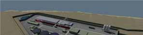

• Onshore pipeline;
• A gas terminal at Bellanaboy, Co. Mayo
By the end of 2004, all of these elements had received full regulatory approval.

• Acquisition and management of key datasets
• Landowner identification and Community Engagement (2007 – ongoing)
• Route Selection and Environmental Surveys (2007

– 2009)
• Environmental Impact Statement (EIS) and Preliminary Design (2007 – 2010)
• Support to Statutory Processes (2009 – 2011)
• Detailed Design (2010 – 2013)
• Construction Support (2011 – ongoing)
All relevant approvals and consents for the onshore pipeline were granted in 2011 [2][3]. The approved scheme comprises 8.3km of upstream gas pipeline, approximately 4.9km of which will be installed within a 4.2m diameter segment lined tunnel, most of which will be under Sruwaddacon Bay (see Figure 3).
By June 2013, construction of the onshore pipeline including the tunnel was well advanced. It is anticipated that the Corrib Gas Field will become fully operational late in 2014.
At all stages of this project there has been an emphasis on quality and programme. This has placed significant demands on the wider Project Team. During the detailed design stage, these factors were intensified as construction commenced. Various challenges that arose needed to be resolved using a multi-disciplinary approach. 3D design played a central role in ensuring that SEPIL’s expectations for the project in terms of quality and programme could be met.
One of the earlier definitions of BIM was “The creation and use of coordinated, internally consistent, computable information about a building project in design and construction”[4][5]. Throughout the process the team endeavoured to create and use coordinated, internally consistent, computable information about the project in the design process and provide this information to project stakeholders in the most valuable format possible.
The project team has utilised technology to enhance and communicate the various constraints (environmental, legislative, physical, ecological, hydraulic geotechnical etc.) and complex design effectively to all stakeholders. This has been achieved in many formats utilising various software products throughout the project’s life cycle. Initially the primary software tool employed by the team was ArcGIS. The project database created enabled the team to organise, manage and access large amounts of technical and environmental data on the project as required. A more detailed description of the GIS use on the project is included in Section V.
Following the statutory process and EIS phases of the project, the project moved towards detailed design with a multi-disciplinary design team made up of specialists in Geotechnical; Civil; Structural; Electrical; Planning; Visual assessment; Surface Water Management; Water treatment and
Environment with input from the SEPIL project team, other specialists and the Contractors’ teams
Technology has played a huge role on the project and SEPIL from the outset facilitated collaboration within the team by the provision of proprietary Enterprise Content Management (ECM) and Information Exchange (IE) technology[6]. This technology provided a central location for the transfer of information between team members and has been used extensively during the project phases. With support from SEPIL, the team embraced 3D modelling techniques and have adopted building information modelling (BIM) workflows transferring data from analysis and design application directly into an integrated model, leveraging 3D modelling techniques to enable clash detection, design visualisation (to optimise designs) and ‘optioneering’.
This 3D model was not only a visual communication tool to convey the infrastructure design to SEPIL, statutory bodies and public stakeholders, but was a vital tool to inform the multidisciplinary and multi-organisational team in its decision making process during the design.
As the project developed and as more advanced software became available, the team worked to incorporate the appropriate amount of data into the models. A number of original methods of utilising the information generated have successfully been investigated. This has included the use of a Unity 3D gaming engine and the direct importation of the single integrated 3D tunnelling compound model into the GIS environment.
The design team utilised a wide range of design software. The process was informed by data generated during the EIS phase and stored in the GIS database. Some of the software packages used at various stages and to varying extents are listed below:
• Pitney Bowes MapInfo

• Esri ArcGIS
• Bentley MX
• Innovyze Infoworks CS
• Autodesk AutoCAD
• Autodesk Civil 3D
• Autodesk Revit
• Autodesk Robot
• Autodesk Navisworks
• Autodesk 3DS Max
• Unity 3D
• Lusas Finite Element Analysis
• MasterSeries Structural Design Software
• Nemetchek Vectorworks
• Acecad StuCad (Now Trimble no longer supported)
Due to complexity and diversity of the Corrib project there has been a great deal of data transfer and data integration required. The team utilised ArcGIS File Geodatabase and MapInfo to provide a central storage location for project data. It facilitated the referencing of all spatial datasets, including site investigation information (geophysical and geotechnical), archaeological data, and environmental designations.
Additional Capabilities of ArcGIS were employed to enable users to view not just the traditional geographical data but other static data sources such as ecological survey notes and field photographs directly in the GIS environment.
ArcGIS enabled spatial data acquisition and management of information which provided coordinated, consistent and computable information to the team. Some of the tasks where the database was utilised are listed below:
• The File Geodatabase layers were used to carry out a comprehensive spatial study of route selection and comparison of route corridors in the initial stages
• Spatial analysis and mapping for the Environmental Impact Statement report.
• Wayleave mapping for the Compulsory Acquisition Order (CAO) application.
• Development of a robust landownership database which allowed prompt access to crucial details especially for the site staff (see Figure 4).
• Demographic and proximity analysis of the proposed pipeline route to the local amenities to support the safety review (see Figure 5).
• Spatial analysis and mapping for the foreshore licence applications for geotechnical investigations.
• Environmental ecological surveys using Differential GPS.
• Model for peat stability assessment using ArcGIS Spatial Analyst.
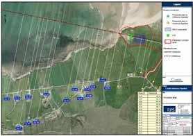
• GIS support during the Oral Hearings.
A user interface was developed for relevant members of the project team to access information without GIS support. E.g. name of registered land owner, length of pipeline within relevant lands, area of relevant lands affected (see Figure 4)
It was vital that all project documents generated were consistent and correct and as the route selection progressed for the modified route the GIS environment enabled changes to be managed successfully.
Proximity of individual dwellings to the proposed pipeline was a vital consideration on this project. Ortho-rectified aerial photography was combined with OS vector mapping to provide a means of indicating the proximity to all local dwellings within a specified distance of the proposed pipeline.
Various alternative pipeline alignments were investigated. Proximity data for each alternative was presented graphically and robustly up-dated (see Figure 5 & 6). The updated Graphical output from this process was found to be extremely useful when liaising with local residents and landowners.

3D modelling was used extensively in the design of the onshore pipeline and tunnelling compound. Three separate areas of the project were modelled:
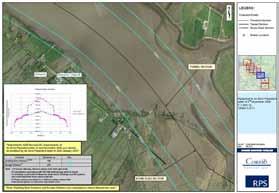
1. Tunnelling compound.
2. Landfall Valve Installation (LVI).
3. Pipeline trench.

These models were developed at different stages of the project, but are fully compatible and were easily integrated when the purpose required it The focus of this section of the paper is the tunnelling compound where some interesting uses of the model will be discussed.
a)
The design of the tunnelling compound was started in October 2010 (see Figure 7).
This was adequate for the Project’s requirements at that stage. As detailed design progressed, the 3D model evolved (see Figure 8).
A 3D model for the tunnelling compound was originally created in AutoCAD for the purpose of producing photomontages for inclusion in the Environmental Impact Statement (EIS). This was based on the available topographical information (DTM) and the compound sitting on flat surface. Plant and equipment were added to the model based on information provided by tunnelling specialists.
b)
At preliminary design stage basic solid modeling was used to combine infrastructure with plant and process elements on the constrained site. As the project developed, these basic objects were swapped out as data, or more developed objects, became available and the process of utilising coordinated, internally consistent, computable information began (see Figure 9).
The compound’s ground profile model was developed in Bentley MX. This was challenging given the various technical, planning and environmental project constraints that needed to be balanced. Using topographical survey data and peat depth probe data, it was possible to optimise the compound surface. Technical constraints included minimum gradients required by the tunnelling contractor and minimum acceptable gradients and radii for access roads within the compound. Environmental constraints included the maximum permissible footprint of the site and the requireme nt to avoid excavation into the mineral soil which lay beneath the peat.
c) Stage 3– Detailed Design

The detailed design of the compound progressed during 2011, with various technical details regarding the tunnelling contractor’s plant, equipment and operational requirements being incorporated as they became available. By the end of February, 2012 the compound design was essentially complete.
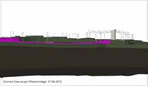
It was found that 3D project visualisations were superior to traditional 2D drawings for helping SEPIL and other project stakeholders quickly grasp the entire scope of the complex design, regardless of their professional background. This was critical in a design team comprising of diverse expertise from various non engineering professions.
In the past, producing visualisation of infrastructure was both time consuming and expensive. By creating a 3D model as part of the design process, the project team was able to leverage this model. By utilising the increased processing capacity of the latest computer hardware, it was possible to produce multiple visualisations of the project’s infrastructure quickly and iteratively (see Figure 10). This was invaluable for balancing technical requirements and project requirements, in particular planning constraints.
and in a manner that was less likely to be misinterpreted (see Figure 11).
Once created, the model became the universally accepted within the Project Team as a central reference for discussing and approving installations and providing various checks during design and construction stages e.g. setting out coordinates. It was also used as a tool to carry out design safety reviews identifying and rectifying potential problems before they reached the site.
The design of some elements of the tunnelling compound required intensive teamwork to solve difficult challenges and reach the optimal solution. Below are some examples where the authors feel the use of the BIM process facilitated the collaborative process by representing the design options rapidly

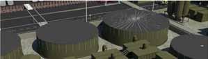


One such challenging element was the Surface Water Treatment Plant (SWTP). This required extensive liaison between RPS, SEPIL and Veolia Water Ireland (VWI). The final design achieved a safely functioning water treatment plant in a challenging location due to space restrictions (see Figure 12). It is likely that the final design would have taken much longer to complete without use of 3D modelling which provided clash detection as well as visualisation of the proposed design solution for review by both the project’s planners and health & safety specialists. The installation was constructed smoothly on-site and successfully commissioned in 2012.
Another challenging element of the design of the tunnelling compound was the Settlement Pond (see Figure 13).
The Settlement Pond is a key element of the surface water treatment system on the site and was installed at a relatively early stage, so as to be operational during the construction phase. The final design uses over 120 pre-cast modular elements, of 4 different types, each with a maximum weight of 4 tonnes. The pre-cast modular approach was chosen for environmental, safety and programme reasons.


Due to project constraints the Settlement Pond is triangular in plan and is located directly above the pipeline tunnel. It includes a rectangular valve and pump chamber. The entire structure was modelled in 3D. The model was utilised to create an animated construction sequencing which aided the contractor with construction on-site (see Figure 14).


During the design, an innovative application within the civil engineering sector was the creation of a first person interactive model. Essentially, this was achieved by exporting the design model into a freely available ‘gaming engine’. It was possible to provide team members with a version of the model that could be explored virtually. The 3D interactive walk had application in terms of advance / remote safety briefings, but also as a means of individuals becoming familiar with the site long before ever making a visit (see Figure 17).
This was a practical application of the 3D modelling software that had significant benefits on-site in terms of communicating the Designer’s concept. Construction of this geometrically complicated structure was completed successfully as planned, by the contractor (Roadbridge Ltd) without a hitch (see Figure 15 and 16).


We believe that there is significant potential and value in this tool to facilitate communication within the project team. It is also a useful means of engaging with members of the public on infrastructure projects, as it provides an instant means of indicating potential visual impacts from any location.
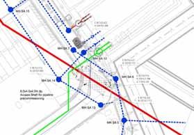
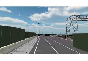
The 3D model was used to facilitate the design of pipework used for the tunnelling process (see Figure 18). Due to the programming of design works, information on the pipework became available at a very late stage in construction of the compound. The 3D model was utilised to rapidly carry out clash detection and provide feedback to the pipework designers.
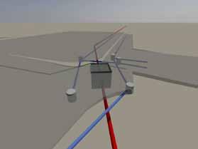
(see Figure 18).
A similar exercise was completed during the construction stage to generate a revised drainage layout design in a congested location of the tunnelling compound to facilitate the Contractor’s preferred construction methodology. It was possible to examine a number of buried structures, services and other physical constraints simultaneously within
the environment of the 3D model (see Figures 19 and 20). An optimised layout was developed and issued to site within a very short timeframe.
As well as using a Trimble 61000-00 GeoXH Handheld GPS, and Trimble Pro XRS to capture survey data on site, the Designer’s Site Representatives also trialled a number of software programs and communication tools utilising tablets and smart phone applications. This was both to view and demonstrate design information to the construction team, and also to transfer on-site information back to the design office. This included:
• AutoCAD WS (Now AutoCAD 360) Autodesk
• Turbo View Pro – IMSI Design
• BIMx - Graphisoft
• Genius Scan- The Grizzly Labs
• Photo Measures (big blue pixel)
• MagicPlan (Sensopia)

A deconstruction model has been developed to assist in the analysis of the future deconstruction and reinstatement of the tunnelling compound (see Figure 21). The model provides SEPIL with a central location for quantitative technical, environmental and cost data.
The application of 3D modelling for this project facilitated efficient engagement and communication with SEPIL, specialists and relevant contractors on various aspects of the design..
The 3D model was also used innovatively for reviewing operational and safety aspects of the compound during the design phase. This resulted in various enhancements, plus a clear understanding of the compound’s complex design within the project team. Design conflicts were identified quickly and addressed long before construction drawings were completed and issued to site.
As the project evolved, the model became central to the design and its uses expanded in a variety of ways that contributed to progressing the design and ultimately delivering the project for the Client.
In the opinion of the authors, the use of 3D modelling on this project and the utilisation of an evolving BIM process highlights the potential benefits of full utilisation of BIM on large multidisciplinary projects.


For this exercise, the 3D model was combined with GIS and material quantities data. This has made it possible to consider alternative demolition scenarios quantitatively and objectively. Currently the design team is investigating 4D BIM utilising Autodesk Navisworks linked to preliminary deconstruction and reinstatement programs (see Figure 22). However, the focus of any such endeavour must be on tangible outputs which benefit the project. In the case of the tunnelling compound, there may be potential to achieve significant cost savings at the demolition stage by being able to plan these works in detail, knowing at all times exactly what and where various materials exist on the site.
On the Corrib Project, RPS typically used conventional means to issue design information to the Contractor for construction i.e. 2D hard copy drawings, but where helpful information was provided to the contractor in a 3D digital format. A significant portion of the hard copy drawings were generated using information from the 3D model, a future goal will be to explore better integration of 3D modelling and a BIM process with the production of such contract documentation.
There is a value to organisations in experimenting with available technologies and in combining these with new technologies. During the design of the Corrib Onshore Pipeline project, a range of technologies were combined, ultimately resulting in the design process evolving into a BIM process. Each advance built on previous work, with many lessons learned. We believe that this has shown how relevant BIM, combined with GIS, is to large infrastructure projects and the potential that 3D modelling has to projects in terms of relating various data sets from many sources.
Originally, the 3D model of the Tunnelling compound was created to provide a geometric check on the design. The site is very restricted in terms of space, with numerous processes and operational requirements. There were many challenges in balancing various project requirements. The model was an invaluable tool in this coordination role from the basic requirement for clash detection, but also as a collaboration tool to explain the requirements of the different stakeholders and reach optimal solutions to many design challenges.
Extensive experience of the BIM process has been gained by the project team utilising as much digital information and datasets as possible in the most usable and efficient manner for the benefit of the project.
Ciarán Butler –RPS Project Manager
David Ward- Lead Designer & Design Co-ordinator
Bryan Coyle- 3D/BIM Application Specialist
Saeed Khan – GIS Manager
The Authors would like to acknowledge the support of the SEPIL project team and the collaboration effort of the wider Project team who included:
• Roadbridge Ltd
• BAM/W&F Joint Venture
• Veolia Water Ireland (VWI)
• Shevlin Engineering Ltd
• Tom Philips Associates
• AGEC Ltd (Ireland)
• Ecological Advisory & Consultancy Services (EACS)
• Hydro-Environmental Services (HES)
• Ordnance Survey Ireland (OSI)
[1] “Corrib Gas Pipeline - Schematic.” [Online]. Available: http://www.corribgaspipeline.com/index.php? page=corrib-gas-project. [Accessed: 13-Sep2013].
[2] “Corrib Gas Pipeline - Home.” [Online].
Available: http://www.corribgaspipeline.com/. [Accessed: 13-Sep-2013].
[3] “Corrib Natural Gas - Ireland.” [Online].
Available: http://www.shell.ie/aboutshell/ourbusiness-tpkg/e-and-p/corrib.html. [Accessed: 13-Sep-2013].
[4] “Autodesk - Autodesk Revit Services & Support - Building information modeling (BIM).” [Online]. Available: http://usa.autodesk.com/adsk/servlet/ps/dl/ite m?siteID=123112&id=9425005&linkID=212 08795. [Accessed: 13-Sep-2013].
[5] “BIM Autodesk original definition.” [Online].
Available: http://d2et.com/html/bim.html.
[Accessed: 23-Jul-2013].
[6] “Enterprise Information Management (EIM) Software Systems | OpenText.” [Online].
Available:http://www.opentext.com/2/global/e nterprise-information-management.htm.
[Accessed: 26-Jun-2013].
2
Office of Physical Plant, University Park, PA
E-mail: 1eric.nulton@psu.edu
2ejg3@psu.edu
Abstract This Case Study follows the construction of two buildings at Penn State University that have utilized Building Information Modeling technologies and processes. This paper is intended to provide the reader with a real life example of the benefits and challenges a project team can expect when implementing BIM on a project for the first time.
At a combined cost of over $100,000,000US, the facilities will serve as the headquarters for the College of Health and Human Development. While the two buildings being constructed are delivered as separate CM Agency projects, they are essentially two subsequent phases of the same large project which utilize the same designer and construction manager.
At the beginning of phase one, no one on the project team had a comprehensive plan for using BIM on the project. However, as the project developed, the University decided to implement its newly created BIM requirements for the construction of the project. Very few of the project participants had the skills necessary to implement BIM at that time, and were forced to learn these skills while still meeting the predefined deadlines. The team encountered numerous issues resulting from the lack of BIM experience, but as the project developed, they began seeing significant benefits from their efforts.
By the time the second phase of the project had begun, the entire project team had honed their skills to a point where BIM was incorporated into their everyday processes. Information was openly shared among the various team members, and potential problems were proactively addressed resulting in significant savings to the project.
Keywords Case Study, Penn State, Collaboration, Virtual Reality, Coordination, BIM Plan
The Pennsylvania State University (PSU) is a multi-campus public research university located across the state of Pennsylvania. PSU owns or leases almost 2000 facilities across its campuses that total nearly 30 million gross square feet of floor space. To manage this space, PSU employs an internal staff of technicians, engineers and architects to maintain, renovate, and oversee the construction.
Penn State University has been implementing BIM to varying degrees since 2007. On the first few projects, BIM was used for specific applications but there was no organized effort to further develop BIM
processes within the University. In 2010, shortly after the release of the Penn State BIM Project Execution Planning Guide, PSU facilities decided to comprehensively adopt BIM on all major projects across their University Park campus. Shortly after that decision, the first phase of the Health and Human Development project was issued for construction.
The intent of this paper is to document the development of BIM by the project team during the course of the project. The paper will analyse challenges, growing pains, and benefits the team experienced by using BIM from the beginning of the project to the construction of the second phase.
The phase one development project shown in Fig. 1 is a 93,500 square foot, $48 million facility completed in February 2013.
implement the BIM goals and Uses for the project. To provide the necessary skillset, the construction manager subcontracted a BIM planning consultant to help assist training their staff, develop the BIM specifications for subcontractors, and run the first few construction coordination meetings. Many of the subcontractors also lacked the 3D modelling skills necessary for direct participation in coordination and had to acquire modelling services from a third party to assist them when necessary.
At the time of design, BIM was required to be used, but Penn State provided little detail concerning specific tools, processes, and communication procedures. Because PSU provided little detail regarding BIM in the contract, Autodesk’s Revit modelling software was used for the design, but the model was not shared with the rest of the project team for pre-construction or construction. While BIM provided enhancements during design, the overall project followed traditional collaboration procedures resulting in a silo’d development process where all parties worked independent and little collaboration was achieved.
At the time the project was issued for construction, the University decided to implement BIM on all major projects over $5 million. While it was understood that BIM is best executed in the early stages of a project, it was felt that PSU could still achieve many benefits by using BIM in construction. PSU developed BIM requirements, a Project Execution Plan template, and issued the requirements to the project team for evaluation.

After the requirements were issued, a BIM kick-off meeting was scheduled with the construction manager, owner, and the designer to determine which BIM Uses would provide the greatest value to the project. The team used the basic BIM Project Execution Plan developed by Penn State Computer Integrated Construction Research Group shown in Fig. 2 as the basic template for the project. The three primary Uses identified by the team were 3d construction coordination, prefabrication, and record modelling.
At the beginning of construction, many of the project participants were unfamiliar with BIM processes and lacked the expertise to successfully
The project team, including Penn State encountered many challenges when implementing BIM on the first phase of the project. Most of the BIM issues resulted from lack of experience with BIM and poorly defined procedures by PSU, but as the issues were identified, the team quickly responded to correct the issue. Some issues such as model tolerances, modelling errors, and decision making capabilities are discussed below.
Some of the most significant issues experienced by the project team were unexpected clashes in the field that were not identified during the construction coordination process. The team fully coordinated the fabrication model and built according to the plans, but in a few situations the clearances were not adequate for the installed equipment and the installers had to lower the ceiling height. As the issue was further evaluated, it was determined that the construction clashes were from an unanticipated beam deflection that the model did not accurately represent and from tolerances that were so precise that they did not adequately allow for construction variations during assembly. This led to expensive re-work or the lowering of ceilings, both of which should have been avoided by using BIM tools.
The project team quickly learned that they needed to allow for greater clearances when coordinating a model. On the second phase, space for fire proofing, beam sag, and slight variations in construction was incorporated into the model, and tolerances were increased when possible to allow for more construction variations.
Errors created from the translation between the 2d construction drawings and the 3d coordination model also presented the project team with avoidable errors. Due to the limited sharing of the design model between the designer and contractors, the entire model had to be recreated by the contractors from the 2d construction drawings. In one situation the model inaccurately represented a cove wall detail. By the time the error was identified during construction, its space was claimed by a duct which was already routed and installed. To correct the problem, the project team had to decide whether to issue a change order to relocate the duct or to eliminate the cove. As the team evaluated the dilemma it was decided that the cost of correcting the problem was too great and the team decided to eliminate the cove detail.
To address this issue in the second phase, the project team agreed to share the design model with all the project participants. While the 2d documents were still legally considered the contract documents, they were also generated from the model. Because the model was the source of information for the project team, the risk of a discrepancy between the drawings, design model, and construction model was virtually eliminated.
The final challenge encountered was the project team’s inability to make important decisions during BIM construction coordination. Due to the lack of experience, the contract documents did not require that the decision makers from all project teams attend the construction coordination meeting. For many meetings, only modellers were present and they did not have the authority to make changes to the facility without approval. This led to unproductive meetings where issues were identified in the model, but no one had the authority to make the necessary decisions required to correct the issue during the meeting.
Because of the inefficacy experienced during the first phase of construction, the contract language for the second phase was modified to require every project team to attend each construction coordination meeting. The individual attending the meeting had to have both the ability and authority to make changes to the model in real time so that problems
could be resolved instantly at the coordination meeting.
While the project team encountered many challenges while adopting BIM for the first time, many more benefits were realized resulting in an overall savings to the project. Three of the BIM Uses which provided the greatest benefits were Construction Coordination, Hangar pre-placement, and Prefabrication.
As is typical with most BIM construction projects, the construction coordination procedure provided the greatest benefit to the project team. The construction model was created by the subcontractors from the 2d drawings and all systems were coordinated prior to beginning construction. Many potential issues were identified through the coordination process that were not initially identified from the 2d drawings. One of the issues identified was the installation locations of the chilled water mains entering the building. Construction coordination identified that the original routing of the piping was not constructible and needed to be relocated. By identifying just that one issue during coordination instead of construction, the project was able to avoid over $30,000 in change order fees.
With the entire model coordinated prior to construction, the MEP subcontractors were able to identify the location of their hangars prior to pouring the floor slab. The MEP subcontractors used the BIM model to locate the position of the bangets which they placed in the floor to await hangar installation. This reduced the time required for placing hangars by 60%.
The use of BIM enabled some of the subcontractors to fully prefabricate their systems offsite. For many this was the first time. By prefabricating, large spans of building components could be constructed to extreme precision in a fabrication facility and assembled in the field. For this project, all the ductwork and much of the plumbing was prefabricated off-site. The ductwork was constructed in 20 foot sections and assembled in field. The complex bends and cuts of the steel pipe was also welded offsite, resulting in additional time savings. While we had no metric for quantifying the savings achieved through the prefabrication
technique in this project, we have found on other projects that on-site fabrication times are often reduced by over 60% and result in higher assembly quality and lower cost.
The second building project shown in Fig. 3 is a $58 million, 132,000 gross square foot combination classroom, office, and laboratory building which began construction shortly after the completion of phase one. Due to the BIM successes in the first phase, the project team decided to expand the use of BIM in phase two in order to increase the benefits achieved.

Due to the much more integrated process adopted by the project team on phase two, many more benefits were achieved by all of the parties involved. At the time of writing this article, many construction BIM Uses are in their beginning stages of implementation and are not discussed due to their incompleteness. The BIM Uses where the greatest benefit has been achieved to date have been; Advanced Design Reviews, Design Coordination, Construction Coordination, and Information Management.
The use of BIM began at the early planning stages of this project where the design team, Penn State, and the construction manager met to develop the preliminary BIM plan and set the goals of BIM for the rest of the project. As shown in Fig. 4 the team agreed on implementing various BIM Uses for the various stages of the project.
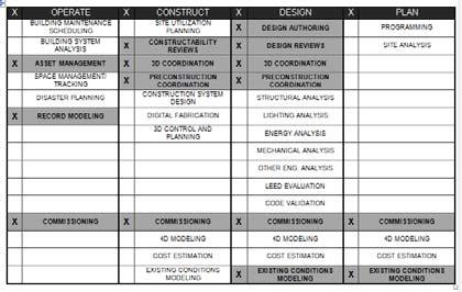
As the facility progressed through the design stage, the project team completed a series of review processes with PSU that included both a mechanical space review and an aesthetic review to quickly allowed Penn State engineers to make design decisions. To perform the work the project teamed up with two research entities currently working on campus; the College of Architectural Engineering’s Computer Integrated Construction Research Group and the Applied Research Laboratory’s Automatic Virtual Environment. These two labs and their staffing help assist the project team in executing both the mechanical space reviews and the aesthetic reviews by refining the design model and converting it into formats that provided the greatest functionality for its use.
A second BIM kickoff meeting was organized after the subcontractors were selected. The intent of a second kickoff meeting is to go over the initial BIM plan, discuss the goals and expectations of all parties involved, and refine any processes that need to be modified.
A mechanical space design review was performed with PSU maintenance engineers to evaluate the configuration of new maintenance spaces such as mechanical rooms and pipe chases. These reviews were not intended to be aesthetically pleasing but to emphasize accessibility and ease of maintenance. The team used the on-site Immersive Construction Lab which is a three screen, semi-immersive 3d environment (Fig. 5) to conduct the reviews. To seamlessly view the model in 3d, the model was converted from a traditional Revit file into the Unity game engine by graduate students assisting in the project. Once the model was converted, the design team was able to virtually walk PSU maintenance engineers through the mechanical spaces where clearances and equipment configurations were evaluated. The PSU engineers evaluated the 3d model and identified multiple areas where the design did not meet the needs for maintenance. The identified areas were then corrected according to the maintenance engineer’s recommendations. While reviewing the model, the PSU
engineers were able to use their experience in maintaining facilities to identify potential problem areas that we unidentified by the design engineers. Many of the issues were minor design changes such as rotating the direction of a pump or tank, but they translated into significant savings in maintenance and accessibility.
While reviewing the model, the participants were able to climb stairs, enter rooms, and walk down halls as if it were real. The simulation was so realistic that participants actually felt that they were walking through the building. The model simulation was used to evaluate the curtain wall assembly, stairways, and general aesthetic features that are traditionally difficult to visualize through a design application such as Navisworks or Revit.
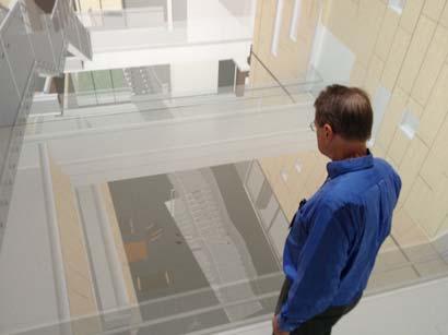
One of the discoveries found during the walkthrough was that the glass railings on the bridge shown in Fig. 6 was too transparent and made occupants uncomfortable. It was decided to then test railings and a more opaque glass.
To provide a specific example, engineers identified a problematic pipe that partially blocked the entrance to a mechanical chase. While this pipe did not violate any clearance or code requirements it presented an impediment that would make future maintenance much more difficult. As with the other issues, the pipe was easily relocated to allow for easier chase access and the total cost to the project was nothing more than a few hours of work.
The project team also conducted an aesthetic review of the design using their on-site Synthetic Environment Applications Laboratory (SEA Lab).
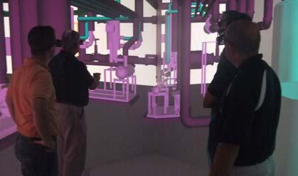
The SEA Lab is a 10’ x 10’ x 9’ fully immersive environment allowing the reviewer to surround themselves from all directions in a virtual representation of the facility. For this review, the Dean, Vice Presidents, and Directors were able to virtually walk through the facility and provide input on building layout and other aesthetic features as shown in Fig. 6.
The value of the simulator to the team is that they were able to produce a very detailed representation of the facility with little cost to the project. The simulator identified multiple changes that would not have been identified by using physical mockups, resulting in more savings to the overall project cost.
One of the more surprising benefits discovered by using BIM was the design coordination process. PSU hired the construction manager to coordinate the designer’s models prior to construction. By the time drawings were issued for bid, the model was required to be clash free. On a regular basis the design was coordinated by the entire team resulting in a full coordination of the primary systems. The level of effort required to fully coordinate the model prior to bid was significantly higher than on a traditional project, but it guarantees that all major coordination problems are eliminated and phase two will not run into construction coordination challenges for major systems.
Penn State is still in the process of determining the optimal level of design coordination on a project. While this process will significantly reduce the time and effort required to coordinate the construction coordination model, it is still unknown the extent to which fabricators will utilize the designer’s means and methods rather than develop their own.
Construction coordination is also being required from all prime contractors participating in the system. The project is currently in the beginning stages of construction, but all subcontractors are required to participate in the construction coordination process. While the design model was fully coordinated, the construction model will have added detail and will require additional, however minimal coordination of systems. In the event the fabricator chooses to modify the routing or style of
any major system, they are responsible for maintaining the clash free environment.
The final BIM enhancement achieved in the second phase of the project is an advanced information management process that is capable of managing data from various sources throughout the construction project.
The initial information requirements were issued by Penn State to the designer and construction manager at the beginning stages of the project. As the design progressed and asset parameters were developed, the design team compiled the data into the model. During construction, the information is refined to incorporate specific manufacturer information and a barcode that was affixed to the equipment the moment it arrived on site. The team used the BIM 360 cloud service to manage the barcode and track it throughout the installation process. A sample of information currently being tracked is shown in Fig. 7.
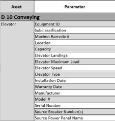
during design to begin developing funding and staffing requirements much earlier.
As this project develops throughout construction, the information is also improved. By the time the equipment is installed by the subcontractor, Penn State has access to all the necessary information required to populate its asset management system.
The costs and benefits to the project discussed in this paper were calculated by the following methods:
Costs and/or results of errors, and missed opportunities were determined by the documentation required to correct the problem in the project. This is typically recorded through the change order process.
The savings in labor due to coordination & fabrication processes were determined through interviews with consultants performing the work and a comparison of the project schedule to historical norms.
Savings from averted issues were developed by the project team and based on the estimated change order cost.
While Penn State has conducted many BIM projects in recent years, this project possibly provides the greatest representation of BIM development by a consistent project team. In the beginning, the team had limited experience working in a collaborative environment, but was still successful in using BIM to improve the project. By phase two, the team was highly skilled in BIM and able to pilot cutting edge technologies.
With the real-time data management enabled through cloud based computing and the data organized according to the university’s needs, all project team members are able to access a single source of information that is guaranteed to be accurate and upto-date.
Penn State has found a great benefit in the real-time accessibility of construction and equipment information. In the past it would often take between six months to one year to receive the necessary closeout information required to develop maintenance funding and schedules. This delay often led to missed maintenance, voiding warranties and reducing equipment life. By using enhanced data management processes, PSU was able to access preliminary operations and maintenance information
While this case study is not intended to promote specific BIM Uses or tools, it provides the reader with a real-life example of the struggles and benefits a team can expect implementing BIM for the first time. This case study demonstrates the value of implementing BIM on a project even if the project team has limited experience. Developing advanced BIM skills and processes is not a trivial task, but with a dedicated team striving to improve themselves and provide the best value to the owner, experience is not always necessary.
[1] Penn State CIC, “BIM Project Execution Guide.” 2009.
[2] PSU AFRG, “Penn State Office of Physical Plant BIM Plan Template.” PSU, 2013.
[3] PSU AFRG, “PSU Facility Asset Attribute Requirement List.” PSU, 2013.
Department of Architecture
University of Kansas, Lawrence, Kansas
E-mail: 1PhD Student, a088a591@ku.edu 2Associate Professor, paolas@ku.edu
This case study focuses on the operational performance of a LEED-rated building with the application of Building Information Modeling ( BIM) to evaluate its capacity to achieve Zero Net Energy (ZNE). Retrofit options for renewable energy implementation are examined in conjunction with scenarios of building operation. In this study, two different BIM processes have been conducted for the energy modeling: object-oriented geometric information modeling (e.g., envelop e, doors, windows, walls, zones, etc.) with a BIM tool and energy modeling (e.g., materials, heat resistance, location, weather data, renewables, etc.) with an energy simulation tool. The simulation model is compared to the real building performance and alternative renewable energy scenarios are evaluated . The results are used to make recommendations for the optimization of building performance and consideration of energyefficient strategies for building performance enhancement. The research points to discontinuities between photovoltaic panel degradation over time and the LEED credit.
Keywords BIM; Energy Modelling; EnergyPlus; LEED; ZNE ; Photovoltaic Panel Degradation
The global contribution from buildings towards energy consumption, both residential and commercial, has steadily increased, reaching figures between 20% and 40% in developed countries, and has exceeded the other major sectors: industrial and transportation [1]. In the United States buildings consume close to 40% of all energy used and account for 40% of global CO2 emissions [2]. Growth in population, increasing demand for building services and comfort levels, together with the rise in time spent inside buildings, assure the upward trend in energy demand will continue in the future For this reason, energy efficiency in buildings is a prime objective for energy policy at regional, national and international levels. In addition, the rising cost of energy and growing environmental concerns have pushed the demand for sustainable building facilities with minimal environmental impact through the use of environmental sensitive design and construction practices [3] In efforts to alleviate resource depletion and environmental damages, the Architecture, Engineering, and C onstruction (AEC) industry has adopted Integrated Project Delivery (IPD) as a highly collaborative building procurement process supported by some prominent technological solutions and tools,
such as the United States Green Building Council (USGBC) Leadership in Energy and Environment Design (LEED) rating system and Building Information Modeling (BIM) [4]
LEED is a green building certification system which encourages a building or community to be designed with consideration of environmental impact, energy savings, and human comfort [5] A LEED rating rewards designers for using strategies that can improve performance in metrics such as CO2 emissions reduction, water efficiency, energy savings, indoor environmental quality, and other environmental impacts Although LEED does not guarantee most efficient performance of a building or community, it is one method to help towards this goal [6]
Building Information Modeling (BIM) represents the development and use of computergenerated building model to support the planning, design, construction and operation of a facility This technology helps architects, engineers and constructors collaborate and visualize what is to be built and identify potential design, construction or operational problems in a simulated environment [7] Linking the building model to energy analysis tools allows for evaluation of energy use and can reduce the costs associated with traditional energy
use patterns during building operation.
BIM can support the study of alternatives more quickly, to achieve LEED certification, and make timely decisions [8]. Despite the LEED certification process for the new construction, it is required to evaluate the building performance during its operation phase and recertify the building under LEED points In cases when LEED certified buildings do not perform as expected in the filing period, building performance needs to be analyzed and optimized during operation [9] Buildings can apply for recertification as frequently as each year but must file for recertific ation at least once every five years to maintain their LEED for Existing Buildings: Operations & Maint enance status [10]
The research points to discontinuities b etween photovoltaic panel degradation over time and the LEED credit Alternative renewable energy sc enarios are evaluated to make recommendations for the optimization of building performance and its capacity to achieve Zero Net Energy (ZNE), in terms of energy consumed vs energy generated during building operation
The ability to accurately predict power delivery over the course of time plays an increasingly important role in the lifecycle of a sustainable building facility Two key cost drivers in the performance of this type of renewable energy systems involve the efficiency with which sunlight is converted into power and how this relationship changes over time An accurate quantification of power decline over time, also known as degradation rate, is essential to all the project stakeholders utility companies, investors, architects, engineers, and researchers alike Financially, the degradation of a PV module or system is equally important, because a higher degradation rate translates directly into less power produced and, therefore, reduces future cash flows [11] Technically, degradation mechanisms are important to understand because they may eventually lead to failure [12]
The National Renewable Energy Laboratory (NREL), has collected data for 2000 degradation rates, measured on individual modules or entire systems ; this research shows a mean degradation rate of 0 8%/year and a median value of 0 5%/year [13] The majority, 78% of all data, reported a degradation rate of <1%/year Thin-film degradation rates have i mproved significantly during the last decade; they are statistically closer to 1%/year than to the 0 5%/year necessary to meet the 25 year commercial warranties
Although the continuous research time rarely exceeded 1 year, this research points to an initial light- induced degradation, with the degradation rate on PV panels approximating 1% per year for single and tan-

The Center for Design Research (CDR) building, located in Lawrence, Kansas, responds to the emerging culture and support of sustainability at the University of Kansas (Figure 1) The design for this new building implements sustainable strategies to minimize environmental degradation, and create an environment that is safe, comfortable and energy efficient
Several sustainable systems have been used at the CDR, including features such as rainwater collection and reuse, a living wall, realtime display of energy usage, wind turbines, solar collectors, electric vehicle charging stations, and a green roof (Figure 1) High efficiency windows were used to eliminate glare effects and reduce solar heat gain during the summer months and heat loss during the winter months The CDR achieved LEED® Platinum status in January, 2013. Data was collected during the design phase, and materials and methods were documented during construction, and verified by a third-party organization when the building began operation In order to receive LEED certification, the facility was evaluated in several key areas: sustainable site development, water savings, energy efficiency, materials selection, indoor environmental quality, and innovation
As part of the case study, the following research tasks were performed: 1) data collection of the building’s real energy consumption and measurement of the amount of energy generation, by the PV renewable systems; 2) modeling, simulation and output aggregation to quantify the energy consumed by the CDR facility; 3) scenarios were evaluated to test parametric variations of renewable systems and building operation schedules The results were analyzed to give recommendations about the optimization of building performance and consideration of new factors for building performance e nhancement or as the modification to the renewable systems
Building performance was quantified using data measurements collected for the past two years for the renewable energy sources on site A base case model was generated to compare to the real buil data. The CDR building was simulated in the BIM software and the energy consumption of the building was quantified taking into account the energy pr duced by two renewable systems: a wind turbine cent to the building, and photovoltaic panels installed on the roof (Figure 2). The building model was ported into energy modeling tool to analyze the buil ing’s energy performance
The energy consumed in operation and the energy generated by the renewables was calculated the base case. A set of alternative scenarios were developed and analyzed a part of a retrofit plan. scenarios involve various combinatory options such as the addition of photovoltaic panels, the replacement of the existing panels to improve energy performance, and changes to the lighting, HVAC and equipment schedule The proposed scenarios correlate with CDR LEED certification rating to enhance the base case
performance level towards a net-zero energy level.
Figure 3 shows the research procedure
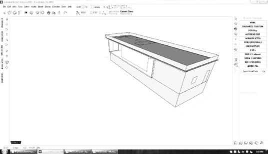
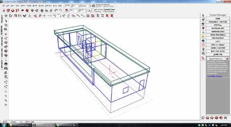

EnergyPlus is a whole-building energy analysis software program developed by the U.S. Depar of Energy. The program performs a comprehensive simulation of the building envelope, fenestration, HVAC systems, and day lighting, based on the Heat Balance Model, where the building is represented as multiple thermal zones [16]. EnergyPlus also includes renewable energy components such as solar thermal hot-water systems and photovoltaic (PV) panels.
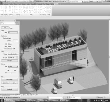
In this case study the amount of energy consumed at the CDR was compared to the amount of energy generated by the PV panels scenarios of operation and PV panel degradation results are used to identify performance enhancement of the facility CDR building model is Architecture, a Building Information
Figure 5 shows a plan view of the model including the room-bounding objects to determine thermal After verifying the analytical volumes exported as a gbXML file
StudioTM and EcotectTM (Figure 4). These tools were used to specify operational schedules and weather data, to be exported as an Input Data File (IDF) EnergyPlus. Finally, the EnergyPlus
Tables 1 and 2 show the parameters explored for the various building performance scenarios: Base Case, Current Performance, and retrofit plans 1, 2, and 3. The energy consumed and the energy generated by the facility were compared as part of the performance evaluation for each scenario.
A computational model of the CDR building is simulated, to establish the base case and primary performance used to qualify the facility for the LEED platinum certification. The number of the PV panels, their efficiency, and the amount of energy consumption by the HVAC system, lighting and equipment, are calculated in the model (Table 3, 4).
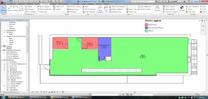
After 2 years of performance in the operation phase, data was collected and aggregated to provide a measure of the current performance of the facility. The facility current schedule for lighting, HVAC and equipment were obtained in consultation with the facility manager and used as an input for energy analysis. Information obtained through a review of the literature was used to establish a rate of degradation in the panels, resulting in a reduction in the generated energy over time. The PV panel degradation was set to approximately 1% per year. In order to consider this factor and calculate the amount of energy generation and comparison to the energy consumption, the rate of degradation was applied to the PV panel’s efficiency.
In this scenario, the area of PV panels is the same as for the building base case, but the degraded PV panels are replaced with new panels to increase the energy generation by the facility (Table 1). In order to reduce building energy consumption and after discussion with facility manager and staff, the schedule for lighting, HVAC and equipment allocated based on building use during the weekdays, weekend and holidays.
This scenario is used to evaluate the energy generation by the panels and the influence of PV location. In the base case, all the PV panels are located on the facility roof. In this scenario, the degraded PV panels are replaced with new ones, and more panels are added to double the original number from the base case, due to the availability of space in the facility roof area. The other consideration in this scenario involves the price of PV systems, which has dropped precipitously in recent years, and could lead to substantial reductions in global PV module prices [17] Similarly to the Retrofit 1 scenario, the facility schedule is updated in the case of HVAC operation, lighting control and equipment use (Table 2).
In this scenario, PV panels are located on the roof and south façade of the facility The degraded PV panels are replaced and there total number of panels doubled. The PV panels are located on the roof and south façade of the facility (Table 1). The building HVAC system, equipment plug load, and lighting schedules are also modified (Table 2)
The design and installation cost of PV systems for commercial rooftops varies significantly based on preexisting building features. For this case study, a $1.99/WP DC total installed price references a 2010 commercial benchmark for PV system [17] WP DC is a scientific term to describe PV panels’ efficiency and size, proportional to the intensity of sunlight striking the surface of the cell The power produces by a PV cell is expressed per peak watt of direct current (DC) capacity in the module, and the price is allocated per peak rated power output ($/Wpeak) accordingly [12]. The CDR roof surface measures 75.86 ft. x 25.85 ft. To double the number of PV panels on the roof top in the Retrofit 2 scenario (R2), the current facility PV types (250 Wp) are considered. The PV panel size is 65 X 40 inches. Using this modular dimension yields the addition of 20 extra PV panels on the rooftop for R2. The estimated cost for installation of each extra PV panel is estimated to be 498.69 $ and the overall retrofit will cost 9,974 $ for the facility.
Three aspects of energy performance are quantified: Site and Source Energy, Energy Use Intensity, and Electrical Load Satisifed (Tables 3a,3b, and 3c)
The Environmenal Protection Agency (EPA) defines Source Energy as the total amount of raw fuel required to operate the building, incorporating all transmission, delivery, and production losses, to assess building energy efficiency. Site energy is defined as the amount of heat and electricity consumed by a building as reflected in utility bills [18]
EnergyStar defines Energy Use Intensity (EUI) as the unit of measurement that represents the energy consumed by a building relative to its size. EUI is calculated by taking the total energy consumed in one year and dividing it by the total floorspace of the building [19]. The CDR facility, the EUI combines electricity and natural gas intensity
Electrical Load is defined as the amount of power consumed in the building. In the CDR facility, the total electrical load is the combination of generated fuel both by the electrical units (electricity from the utility) and PV power used to satisfy the part of the electrical load
Table 3a, 3b, 3c shows that the site energy increased and HVAC use and electric load have the same trend in the current performance of the facility. Table 4 compares the energy generation by the PV panels between the base case model and the
current building performance. Table 5 provide the energy use summary for base case and current building performance. Figure 6 shows higher energy consumption during the 12-month period for the CDR current building performance.
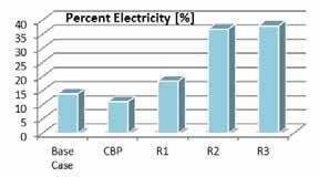
Figure 7a shows the electricity generated by the PV panels for the Base Case, the Current Building Performance (CBP), and proposed retrofit plans (R1, R2, R3) respectively. Retrofit 3 provides higher electricity percentage. Figure 7b shows the Energy Use Summary for the Base Case, Current Building Performance (CBP), and proposed retrofit plans R1, R2, R3, respectively for first month in each season. The consumption decreases from the Base Case to R3 in all of the cases. Figure 7 (c,d,e) show a reduction in the carbon equivalent, CO2 emissions and HVAC system electricty from B to R3. Finally, figure 7 (f,g) represents the resulting cost difference and monthly savings in each scenario.


An analysis of the CDR facility lifecycle cost of electricity shows that the R2 and R3 plans would save 1.31 $/ft2 and 1.42 $/ft2 with total 2560 $/year and 2,806 $/year energy savings respectively (Table 6). The predicted plans to double the number of PV panels would be paid back in nearly 3.5 years, with a return on investment (ROI) of almost 3.5.
Based on the results obtained from the facility base case and current performance scenarios, the facility energy generation rate has decreased, whereas energy consumption has increased since its LEED platinum certification In order to retrofit the facility and improve the current building performance, three retrofit plans were quantified with the respective energy consumption and generation in each scenario. Each retrofit plan demonstrates a positive influential effect on facility energy performance (Figure 7) It should be noted that the obtained results is solely based on PV panels addition and the influence of other factors such as wind turbine power generation or required lighting for the green wall, need to be assessed in future works.
A key observation is the very low points in the LEED checklist for the renewable energy, which generates only 7 points for 13% of renewable energy onsite (Table 7) Because of high percentage of renewables onsite (17% of PV panels), the CDR facility would obtain these 7 points whether the renewables perform in the optimum way or degrade after some years of use. Therefore, further research is needed in the assessment of the LEED checklist in the evaluation of building performance. It is recommended that the allocation of additional LEED points for added onsite renewable energy systems should be reconsidered based on the actual efficiency of those systems rather than the number of units installed The upgrade of LEED criteria or introduction of new green initiatives in the case of renewables should be an important direction for the future research.

Another consideration for further research in the case an existing LEED certified buildings involves the correlation of window-to-wall ratio, the type of glazing (U factor, SHGC) and the building orientation, in order to make retrofit recommendations to improve energy consumption and increase savings for the facility.
In terms of interoperability between BIM and multi-zonal modeling for energy analysis, it should be noted that BIM objects’ physical properties did not include thermal properties. For instance, a window type in gbXML created in Revit, 2013 does not export all the necessary information for a window object in EnergyPlus which is defined geometrically and physically based on material layers Thus, window glass properties such as U value need to be specified within the energy modeling tool [20] Further research is needed to assess the interoperability of later software releases to include the necessary information for energy simulation.
In this research, a LEED-platinum-certified building was selected as a case study and was studied for its operational performance with the application of BIM. The main objective of this research was to evaluate the LEED-certified buildings during the operation phase with recommendations for possible retrofit plans to enhance its energy performance. This research compared the results from the simulation model and the real building performance The influence of renewables on energy consumption and generation was analyzed using EnergyPlus, in order to evaluate three scenarios of operational use and the impact of energy generation by photovoltaic renewable energy systems.
A base case model was compared to the current performance of building to evaluate the lifecycle cost for three retrofit plans The results obtained show a direct impact on energy reduction, CO2 emission reduction, and higher energy generation through renewable energy. With regards to the cost benefit analysis, retrofit plans reduce electricity bills annually in the facility. The payback period for Retrofit 2 and Retrofit 3 is 3.5 years due to annual energy savings.
In conclusion, the capability to increase energy generation by the facility does not have any effect on the building certification process. In order to motivate the facility owners and introduce the financial benefits of achieving higher LEED certified building, an upgrade the LEED checklist is needed to achieve both a reduction in energy bills as well as a tax deduction. This revision of the current LEED rating system could improve the potential for LEED rated buildings to achieve Net-Zero Energy status and certainly increase the return on investment
The author would like to thank Professor Greg Thomas, Director of the CDR for his valuable support.
1 Perez-Lombard, L., J. Ortiz, and C. Pout, A review on buildings energy consumption information. Energy and buildings, 2008. 40(3): p. 394-398.
2 Schlueter, A. and F. Thesseling, Building information model based energy/exergy performance assessment in early design stages. Automation in Construction, 2009. 18(2): p. 153-163.
3 Azhar, S., J. Brown, and R. Farooqui. BIM-based sustainability analysis: An evaluation of building performance analysis software. in Proceedings of the 45th ASC Annual Conference. 2009.
4. Garzone, C., US GREEN BUILDING COUNCIL and the LEEDTM GREEN BUILDING RATING SYSTEM. 2006.
5 Gowri, K., Green building rating systems: An overview. ASHRAE Journal, 46 (11): 56-60, 2004. 46(PNNL-SA-42827).
6 Todd, J.A., et al., Comparative assessment of environmental performance tools and the role of the Green Building Challenge. Building Research & Information, 2001. 29(5): p. 324-335.
7 Azhar, S. and J. Brown, BIM for sustainability analyses. International Journal of Construction Education and Research, 2009. 5(4): p. 276-292.
8. Patel, A., LEEd Calculation with BIM. HOK Company Online Source 2012.
9. Newsham, G.R., S. Mancini, and B.J. Birt, Do LEED-certified buildings save energy? Yes, but…. Energy and Buildings, 2009. 41(8): p. 897-905.
10. Council, U.G.B., LEED for Existing Buildings: Operations and Maintenance. Last Updated, 2008.
11 Short, W., D.J. Packey, and T. Holt, A manual for the economic evaluation of energy efficiency and renewable energy technologies. 1995: University Press of the Pacific.
12 Meeker, W.Q. and L.A. Escobar, Statistical methods for reliability data . Vol. 314. 1998: Wiley-Interscience.
13. Jordan, D.C. and S.R. Kurtz, Photovoltaic degradation rates an analytical review. Progress in Photovoltaics: Research and Applications, 2013. 21(1): p. 12-29.
14. DeBlasio, R., D. Waddington, and L. Mrig, Outdoor performance and stability testing of thin film devices. Solar cells, 1987. 21(1): p. 343-351.
15 Hahn, M., W. Berry, and L. Mrig. Comparative short term/long term field test performance and stability of tandem and single junction a-Si modules. in Photovoltaic Specialists Conference,
1990., Conference Record of the Twenty First IEEE. 1990. IEEE.
16 Crawley, D.B., et al., EnergyPlus: creating a new-generation building energy simulation program. Energy and buildings, 2001. 33(4): p. 319-331.
17. Goodrich, A., T. James, and M. Woodhouse, Residential, commercial, and utility-scale photovoltaic (PV) system prices in the United States: Current drivers and cost-reduction opportunities. Contract, 2012. 303: p. 2753000.
18 Star, E., ENERGY STAR Performance Ratings Methodology for Incorporating Source Energy Use. Understanding Source and Site Energy. Environmental Protection Agency. Date Accessed, 2009. 12(6): p. 09.
19 Chung, W., Y. Hui, and Y.M. Lam, Benchmarking the energy efficiency of commercial buildings. Applied Energy, 2006. 83(1): p. 1-14.
20. Moon, H.J., et al. Case studies for the evaluation of interoperability between a bim based architectural model and building performance analysis programs. in Proceedings of 12th Conference of International Building Performance Simulation Association. 2011.
Headcount Engineering Solutions, 4e Fingal Bay Business Park, Balbriggan, Co. Dublin
E-mail: philip.tyrrell@headcount.ie
Abstract While Revit and similar suites have many excellent features as BIM tools, it has been the experience of process and piped systems designers that their piping, HVAC and electrical containment modules (MEP) do not store or output data in sufficient detail to satisfy the requirements of a process BIM model. This especially holds true for Ireland in light of the current and potential large scale projects that are likely to be developed in the coming decade.
In this paper the author examines the type and extent of piping data needed to build a comprehensive process BIM model and highlights the limitations of the leading BIM suite in this regard.
For the mainstream process plant design packages he highlights their strengths and weaknesses in the context of the BIM model.
The specific findings on the interoperability of one of the leading products and the resultant qualitative and quantitative improvements to the BIM model to be handed over to the client are discussed in some detail.
The conclusions are twofold; (1) A single BIM suite cannot do it all and
(2) It need not do it all – as the more comprehensive data available from the specialised process pipe work packages can be seamlessly integrated into the BIM model. This bein g achievable with the use of a single, cross platform system with more BIM benefits for project planning, visualisation and end user suitability.
Keywords MEP, Alternatives, Isometrics, Process Plant, INTRODUCTION.
There are a number of BIM drawing / design suites on the market currently. In recent times there has been a tendency for the industry to focus all its attention on just a small few or even only one in some circumstances. While all the suites have their benefits, Revit, which has been getting the most focus, is perhaps the widest ranging and probably the right choice to deliver about 80% of any BIM project, until you get to the services and process systems that is.
So
The first question we need to ask is where is the construction industry going in Ireland right now and for the foreseeable future?
We had a good run here during the late
90's and early 2000's. Hotels, office blocks, theatres, conference facilities and stadiums were the norm and in the background there was significant investment in the manufacturing sector across the field of industries. However the world has changed, we are in a recession and nowhere more so than in the construction industry. Recently things are a little better than they were a year or two ago. There are a few projects being undertaken and people are getting back to work.
Most of these projects are in one of the manufacturing fields with a few office fit out projects dotted around. It is expected there will be schools and other public spends soon, however these are unpredictable , at best.
It is generally held that the majority of
construction in Ireland in the coming decade will be concentrated in the manufacturing sector and as such they will have major Process Systems to be considered.
That leads us to the point where we need to think about how we are going to bring the equipment and piped, cabled and ducted systems into our BIM model. When we look at what is out there now and what most people are talking about we are being pushed towards a certain group of packages. All of these in one form or another use an MEP module or are paired with an MEP package.
Because these are bundled in, there is an obvious perception that they are then suitable and sufficient to run all the required services in any type of building be it hotel or pharmaceutical facility.
This is not the case however. Most MEP packages are limited with only a few built in specifications and components and do not allow for the level of information required in process facilities. With the trend leaning towards off site fabrication the need for more detailed and accurate information is only becoming greater.
We are actually going back to where we were in the late 80's and 90's when it was the consultants who issued out coordinated drawings along with isometrics for construction. This responsibility was not and should not be left to the contractor companies because the end result is a large number of change controls and extras which only add cost.
MEP packages are not the solution especially for the piped systems.
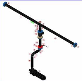
There is an argument to be addressed that the MEP packages can be built to give most specifications that would be required and to a point that is true. We can start building the specifications and components piece by piece and eventually we would have a large amount of what is needed but there will be limitations reached. (detailed valve sets, pulled pipe and complex equipment for example). Live connection points are an issue in many cases also.
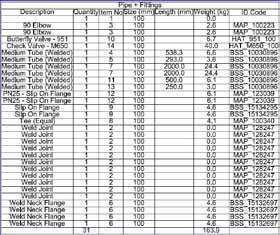
Some of the packages will allow you to create "Spool" drawings. You can also pull out a bill of materials from the spool drawings. However some of the more popular MEP systems cannot create these spool drawings in themselves and need either an add on package or you must export to another MEP package that has the facility. These spool drawings are limited on the amount of
information that can fit on a single page as they are created as a scaled 3D isometric view of the pipe in question. They are not created automatically and need more operator input to get an acceptable result. "Field fit" points cannot be entered into the model so making for more input again.
For on and off site fabrication to be efficient the only drawing type that is acceptable is a true isometric.
IV
So if we say to you that the MEP packages are not ideal then what should we all be using?
The obvious answer is one of the number of process pipe / plant design suites. These are more suited as they start off with a much more detailed and wide range of built in specifications and components. There are much greater systems built in which can build all sorts of equipment and complex multi part components.
The specification editing and creation is
more user friendly and produces a more useful end result. The output being detailed orthographic and isometric drawings which speed up off and on site fabrication. The costs are better quantified and controlled and end of project extra costs and red lining should be a thing of the past.
The integration of the design into the BIM system starts at a much early stage by using the integrated P&I.D. systems that link directly into the 3D pipe design saving on time and operator input yet again.
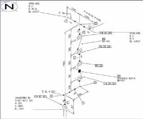
The amount of work that has been done on these packages in the last year across many of the engineering and design firms is phenomenal. Approximately 32,000 components have either been created from scratch or been harvested from vendors on one project alone.
In some cases much of the specification data can be shared between the packages saving time again.
As the software companies work closely with the users these systems are improving in leaps and bounds each year while some MEP systems are falling further behind.
What are we saying should be the way to move forward? Well the bulk of the people working with the 3D packages at this point have a good amount of experience with at least one of the process piping versions.
So YES, as we said MEP can do a good amount of what is needed in a BIM project especially if you are only talking about the "service building" (Hotel, office block etc.) but why would you want to restrict yourself in this way. As a colleague once said "You can use a screwdriver as a chisel but why would you when you have a chisel in your toolbox". Process packages are already being used and can give a much more useful deliverable in the same amount of time . You will get more information out and as such should easily and quickly find yourself seeing financial savings.
There are still unfortunately a few stumbling blocks to this concept. Some of the "Plant Design" suites have forgotten that all projects will include electrical containment and even in our climate most will have some ducted services also. These process packages do not facilitate the drawing of either of these and we are put in the unfortunate position of having to purchase extra add on packages in the MEP field. This is something that needs to be addressed. There is an urgent need for these to be developed to fully integrate design systems across all the different platforms that have the detail and output level for electrical containment and duct equal to the piped systems.
Others still, have some serious stability issues such as continuous crashes and loss of work that need addressing.
All these are being or will be addressed in the coming years and updated releases and soon there will be no obvious reason to justify using a standard MEP only package for any type of project.
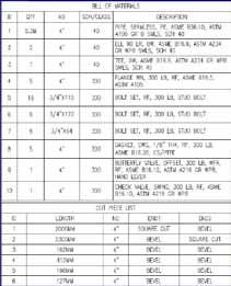
Some of the packages that need to be brought together to achieve the ideal BIM design system will not work seamlessly together.
Some will import other 3D models but will drop the built in data so you are left with a
space saving composite model. Others need patches or enablers to even show the imported drawings properly and some will just not work with each other directly at all.
So we look to the package that brings almost all of them together while retaining the information, namely Navisworks.
Navis, being a tool that we can utilise from early in a project for such basic things as reviewing a model or group of models right up to the complexities of model simulation & analysis, 5D scheduling and animations gives us the flexibility to work in different platforms.
It has been commonplace that the client or project initiator would direct that a particular piece or suite of software is used by anyone who wishes to work on their project.
In our experience this has led to having to invest in new software and training continuously which in many cases only gets utilised for that one project.
Utilising the likes of Navisworks there is no longer a need for everyone to use one system. The "end user" of the model should only need to use Navisworks Freedom for day to day information access while the core data is stored, controlled and updated by an offsite custodian. This also leads to cost savings at many levels.
All BIM projects looking to achieve the appropriate and expected level of information in the model should have its services and process systems designed and coordinated in an advanced Process Design Suite and not a more basic MEP package or add on. There are no arguments to support using MEP as there are no real extra cost or time savings in doing so. For the same input you will achieve a much greater output.
Alan Redmond1, Bob Smith2 and Deke Smith3
1Department of Engineering and Built Environment, Anglia Ruskin University, Chelmsford, UK
2Department of Engineering and Built Environment, Tall Tree Labs, Huntington Beach, USA
3National Institute of Building Sciences, buildingSmart Alliance, Washington DC, USA
E-mail: 1alan.redmond@anglia.ac.uk 2bobsmithttl@gmail.com 3dsmith@nibs.org
Abstract The main objective of this paper is to identify the design criteria for a BIM Education Resilient System STEM program. The curriculum’s development will semantically relate to resilience concepts with Systems Engineering and Building Information Modeling (BIM) practices and standards. The Sustainable Facilities and Infrastructure in Constrained Environments’ (SuFICE) in advancing STEM to Support Facility Design, Construction, Operations and Maintenance collaborative project is to be led by The National Institute of Building Sciences, and Total Learning Research Institute. The participating organizations intend to: engage representatives from across the building and infrastructure industry to revise existing STEM curricula and materials and develop new curricula and materials that recognize the role of science technologies important to both education and the building industry.
Keywords BIM, MATE, Resilience, Course Curriculum, Decision Model, OPR .
There is a growing concern within urban and environmental economists’ way of thinking that a collision between climate change and urbanisation is in fact unavoidable if governments continue to take no action. The root of the problem is simple the world’s cities account for 70% of emissions; however they cover 2% of the planet’s land mass. It is estimated that 59% of the world’s population will be living in urban areas by 2030 coupled with the fact that every year the number o f people who live in urban areas grows by 67 million with developing countries accounting for 91% of this trend. The extreme densities of these areas create vulnerable consequences from increase intensity of frequent warm spells, heat waves and extremely h igh sea levels. Urban areas are naturally energy-intensive due to the increased transport use, heating and cooling and economic activity to generate income. However, it is because of these dependencies that future populations will be stripped of their asse ts and
livelihoods due to future climates changes affecting water supply, physical infrastructure, transport, ecosystem goods and services, energy provi sion and industrial production [1]
There are four key roles for governments to play: (i) as a regulator with regards to aspects such as building and planning, (ii) as a policy maker for issues that directly affect but go wider than the industry, such as energy efficiency and climate change, (iii) as a sponsor to support research and development and articulate a vision for the future, and (iv) the role as a client the government can make the greatest progress in implementing the sustainability agenda (it is also within this role that the authors of this paper contest that the US government should provide mandatory system analysis ‘Multi-Attribute Trade space Exploration’ (MATE) at the design stage of government developments through the use of BIM Life Cycle Analysis and tools such as Owners Projects Requirements - OPR tool). Evidence has indicated that even with the progression of Private Finance
Initiative a high level of government commitment is inevitable due to the nature of public goods that there will always be a significant element of public sector procurement. It is because of the public sector that the construction industry has a unique role to play in a sustainable economy because government buildings have a life cycle reaching 100 years [2].
The research methodology identified in this paper adopts MATE’s applied decision theory approach for operational environment of engineering systems characterized by disturbances such as 9-11 psychological attack on the US interdependent economy causing $1.2 trillion loss in the valuation of US stocks and engineering systems vulnerable to natural threats, Hurricane Katrina ‘New Orleans’ flooding 80% of the city and costing 2,000 lives and over $80 billion in damages [3].
The objective of this paper is to develop an architecture that can convey new knowledge to students, such as MATE for survivability which can be introduced as a system analysis to improve the generation and evaluation of survivable alternatives during design, applying decision theory. However, in order to achieve such an objective the individual perspective learning outcome must link through a deep learning experience ‘active learning’ (understanding a subject, making connections and recognizing underlying principles). Demonstrations of such learning outcomes will be possibly through case studies such as California HSR Authority and the California Growth Council High Speed Rail (HSR) network and the use of Computational Fluid Dynamics (tool for predicting engineering flows since the early 1970s, due to the development in computer programming and turbulence models) and OPR tools incorporated into BIM models.
The concept of BIM is to build a building virtually, prior to building it physically, in order to work out potential problems simulate, and analyze potential impacts. As in reality all the information for a building already exists electronically and that this is the catalyst which makes implementing BIM a possibility. The bi-directional virtualization capability of identifying virtual problems will minimize waste on-site, as products will be delivered when needed (known as 4D programming), more components will be built and pre-assembled off site in controlled environments. The completed model will be the main source for planning and executing changes throughout the life of the facility; it will be tested and updated to validate compliance with the
original design intent, such as energy usage for analyzing the most cost effective/performance envelope required. In Figure 1 the many facility lifecycle (building conception, design, building and process development, construction, supply chain) relationships are displayed, such as, systems, space and overlays. Each system can operate dependently or independently from the other by excha nging data using ontologies, such as the International Framework for Dictionaries (IFD) to create userfacing requirements that are mapped to IFC objects for implementation in software [4] The market failures of sustainability relates to not being able to close the gap between traditional, project-based approaches to more integrated approaches involving on-site installation of purpose -made components [2].
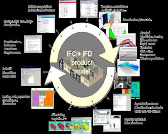
Multi-Attribute Exploration For Survivability is a system analysis methodology used to improve and evaluate survivable alternatives during the conceptual design (applied decision theory to the parametric modeling of thousands of design alternatives across representatives distributions of disturbance environments) stage. To further breakdown the reasoning of this methodology engineering systems research is distinguished by particular emphasis on:
Interdisciplinary methods which span technology, management, and policy;
Temporal system properties, commonly referred to as “ilities” (may be defined as temporal system properties that specify the degree to which systems are able to maintain or even improve function in the presence of change – explicitly recognising requirements and the performance of
system architecture to deliver value to stakeholders).
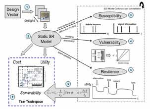
The interconnectedness of product systems with enterprise that develop and sustain them; and
Value stream complexities a rising from stakeholder heterogeneity.
In relation to the conceptual design stage as an area of considerable focus – ‘empirical evidence suggests that the lifecycle value delivered by systems is primarily determined at the beginning of development programs, highlighting it as critical in good decision-making.’ Applied to conceptual design, tradespace exploration (extending traditional trade studies, which may consider a small number of alternative designs, build on tradespace exploration application by adding computer-based parametric models and simulations) may be used as a quantitative tool for evaluating the benefits, costs, and risks of alternative architectures informing critical front-end decision making. Essentially MATE is all about decoupling the design from the need through using tradespace exploration to generate a decision making frame work.
On an overall reflection: resilience system engineering focuses on creating enterprises with supply chains robust to high-impact disturbances such as achieving cost efficiencies ‘leaning’ of global supply chains that are extremely fragile to disruptions [6] and in October 2006 USC and MIT identified resilience engineering as the top priority for system of systems [7]
requiring knowledge) activities rather than understanding. This type of learning does not enable the student to connect with information that has been previously identified. However, deep learning makes connections and is based on student center activities, such as problem-based learning, reflection, case studies (relate to this papers California High Speed Rail), applications (OPR, Rapid Fire Model and CFD tools) evaluation and analysis (MATE). It has also been recognized that deep learning is associated with constructivism (a learning process which allows a student to experience an environment first hand, thereby, giving the student reliable, trust -worthy knowledge) in that it requires the development of schema and the making of connections. With regards to the full nD suite of BIM it allows the students to test in a hypothetical environment (virtual) their learning skill in an active role. Scales through the use of citing several authors highlights that there are a number of ideas about how people learn such as visual and kinaesthic learners (active) [8]
One such visual and kinaesthic learning environment is ‘BIMStorm’ an international open Web platform scheduled event which takes place internationally and is organized to demonstrate new innovative design processes. Any event can be attended virtually or physically with a ttendees participating in either environment. The participants use innovative tools such as, Web-enabled multi-user platforms to access BIM applications. Images of buildings are visualized through Google Earth, via a network link, to the Onuma System open BIM model server. The structure of the event encourages individuals or teams to use their preferred BIM tool of choice. This enables multiple studies on various tools for LCC, curtain wall systems, energy analysis, constructability, interior design, mechanical and electrical plant systems and structural systems. This type of collaboration allows changes to be made in design at the very early stages, as various disciplines can graphically visualize the design decisions, based on feasibility studies and development costs [9]
In order, to champion the teaching of MATE techniques for BIM, the main issues associated with learning must be evaluated. There are two types of learning: surface and deep learning. Surface can be characterized by rote learning (for example; learning multiplication tables in a repeatable sequence), memory and low-level cognitive (process of
In order, to formalizing ways to choose appropriate sustainability assessment tools, Gasparatos and Scolobig have synthesized three major approaches to performing sustainability assessment, and the associated values that different tools provide analysts. Their work concentrates only upon exposing the weak and implicit values and assumptions of a dozen planner oriented projects. This work thus provides a civic and legal domain foundation for a BIM engineering and social network assessment framework [10].
a) OPR Tool
In order to have a fully integrated highperformance building where the design of the building enclosure reaches beyond the aesthetics and begins to support comfort and productivity for the end user it is critical that durability and performance receive the same weight as programming and massing. He further highlights that these tasks are all interlinked but must be fully considered at the early design stage. Lemieux identified the importance of the ASTM task force created in 2009 which worked closely with NIBS to align a standard. The alignment of the performance attributes included in Annex A1 of ASTM E2813 formed the basis of the online OPR tool and the 2007 Energy Independence and Security Act (EISA) [11]. It is anticipated that the OPR tool software will offer the industry for the first time, full transparency that utilizes quantifiable metrics of building performance to calculate the relative cost/benefit of decisions made during the pre-design and design phases of the building enclosures commissioning and project delivery process.
illustrating the life cycle information, facility resistance and operations, and standard scope of a building.
The DHS are focusing on expanding from looking at the building enclosure to also include structural, mechanical and electrical systems to add whole building coverage for new and renovated office building construction [12]. The technical aspects of the OPR tool incorporating the whole building coverage would only benefit from the architecture of cloud computing and BIM. The characteristics of cloud computing: i) Static features – the interface and commands are roughly the same regardless of where and when the applications are used, ii) Standards for data interchange – options for saving data or for importing data are standardized, iii) Modular interactivity – the ability to allow one application to interact with another, and iv) Inter applications communications – the ability of an application to use the service features of another coupled with BIM interoperability structures:
1) BIM – cost benefit analysis relating to that of structured information that is organised, defined and exchangeable
2) The bi-directional virtualisation capability of identifying virtual problems will minimise waste on-site as products will be delivered when needed (4D programming), more components will be built and pre-assembled off site in controlled environments.
3) Each system can operate dependently or independently from the other by exchanging data using ontologies such as International Framework for Dictionaries to create user-facing requirements that are mapped to IFC (public product data model exchange) objects for implementing software.
In 2010, the US Department of Homeland Security (DHS) Science and Technology Directorate’s (S&T) Infrastructure Protection and Disaster Management Division asked the NIBS to assist them with a new project that would ensure building owners have a way to incorporate highperformance attributes, including: energy conservation, safety, security, durability, accessibility, cost benefit, productivity, sustainability, functionality, and operation consideration. The ultimate goal of the developed system was to cover the key systems of the whole building that are impacted by natural and manmade hazard events, as well as their relationships to operational performance of different commercial building types. Figure 3 shows the dashboard interface of OPR tool
Resilience thinking is the post-911/Sandy multiplesolutions thinking for designing -out vulnerabilities in Built Environments: it runs against traditional efficiency (single-solution) thinking. This curriculum would draw on NIBS specialists to design UScentric teaching of new resilience/efficiency systems. Use of BIM in utilising digital communication technology is key, enabling a step -change in students producing design information that is organised, defined, rigorous, reusable and exchangeable. This curriculum would semantically relate resilience concepts with systems engineering and BIM practices, whilst engaging students. The proposed scheme suits virtual environments as much as hands-on field/project work and design stud io work, providing the flexibility that is considered to enhance student engagement and which also suits

different university budgets, staff resources and existing curricula.
The main aim of the course is to teach students how to use the full nD suite of BIM resilience tools such as 3D (three dimensional modelling), 4D (time – programming), 5D (costing) and 6D (sustainability). The best practices of this model will be used for communicating through visualization, connecting to project teams and p romoting innovation during the life cycle of a project from ‘cradle to grave.’ These tools will improve resilience through increased Public Private Partnerships (PPP) as urban hubs will be designed to reduce disasters or eliminate long-term effects to people and their property from hazards and to respond to and cover from major incidents.
The course will focus on using concept maps to graphically illustrate the results of the decision making techniques upon deciding what BIM tools should be used for specific problems. As the majority of the applications will be web-based the main integrated project can be hypothetical such as, designing and planning virtual communities of homes and infrastructure for disaster relief or as in the case of HSR; infrastructure planning.
Introduction to BIM and Resilience Systems
Cloud BIM and Building Collaborative Technologies
High Performance Attributes of Building Envelopes – OPR
Architectural Design - 3D modeling
Project Planning and Modeling – 4D modeling
Quantity Surveying (finance, insura nce and real estate) – 5D modeling and Integrate Project Delivery
Urban Use and Resilience – Rapid Fire Model
Energy Integrated ICT Applications and IRIS – 6D Modeling
Facilities Management in Co nstruction (IRIS and FUSION) – 7D modeling
Integrated Project (Collaboration of all disciplines in a group project).
The Typical Delivery of a Module based on the Following Metadata Structure
Module: Introduction to BIM and Resilience Systems
Module Description: This module will introduce the concepts and technologies of Building Information Modeling with emphasis on improving resilience for urban design.
Module aim: To provide students with a broad understanding of the different aspects of BIM within Built Environment. This module will assist the student in designing principles based on resilience, sustainability and cost
On successful completion of the module, the students will be able to:
- Describe the importance of BIM and resilience systems in sustainable design.
- Prepare Business Process Diagrams maps and Concept maps based on multiattribute decision making techniques.
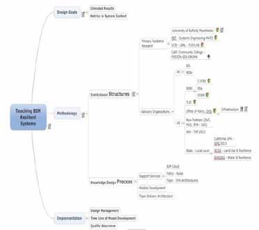
- Identify the capabilities of MultiAttribute Tradespace Exploration for Sustainability.
- Use a range of resilience tools such as, OPR, CFD and Integrated rapid visual screening.
Define the supporting open standards for exchanging information and data required to support a successful BIM strategy.
Participate in BIMStorm events using virtual scenario to demonstrate cost benefit analysis based on commercial advantages of choosing the most resilient design at the feasibility stage of a development
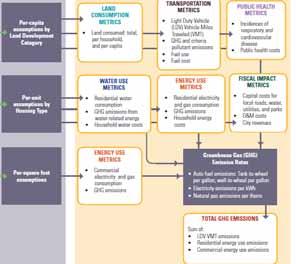
Information such as, demographic projects, population, housing units and jobs incorporate the following data: transportation (baseline auto ownership and maintenance cost per mile), building energy (baseline energy use per existing residential unit and commercial sq foot) and water (baseline per-capita water use). The Rapid Fire Model analyzes up to four scenarios at a time with each scenario consisting of two components, land use option and policy packages. The land use option defines three specific Land Development Categories (LDCs): urban, compact and standard. The model is loaded with four default land us e options (i) business as usual , (ii) mixed growth, (iii) smart growth, and (iv) smart growth plus. The policy packages categories are auto and fuel technology (i.e. combustion engine vehicle fuel efficiency), building efficiency (i.e. energy efficiency/conservation improvements for base/existing residential building stock – yearupon-year % reduction) and utility portfolio (i.e. residential and commercial building electricity emissions – Ibs C02e per KWh). With regards to the scenarios the policy packages can analyse a range of futures such as business as usual relating to current trends, to a progressive case that represents significant policy action.
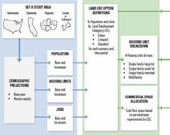
Figure 4 identifies how key policies (percapital assumptions by land development category, per-unit assumptions by housing type, and per-sq foot assumption) lead to influential decision criterion based on total GHG emissions output (sum of Light Duty Vehicle – LDV, Vehicle Miles Traveled - VMT emissions, residential energy use emissions and commercial energy use emissions).
The vision of the California process is to explore the role of land use and transportation investments in meeting the environmental, fiscal, and public health challenges facing California over the coming decades. California HSR Authority and the California Growth Council have seven strategic goals: 1) highlight the unique opportunity presented by the HPR network, 2) frame California development issues such as, meeting GHG reduction target, 3) illustrate the connections between land use and other major challenges, including water, energy use and economic development, 4) link land use and infrastructure priorities to the mandated targets as set forth by AB32, SB375, and the California Resource Board, 5) produce scalable tools, which can measure the impacts of land use and transportation investment scenarios, 6) build upon original plans to produce state wide growth, and 7) connect state and national goals for energy independence, energy efficiency and green jobs creation to land use and transportation investments [13]
These goals will be incorporated into an overall project module for the students to work on in a BIMStorm environment as a direct and participant observation case study implementing all of the proposed design modules, in order to advance the students active thinking, collaborating ideas (through use of Cloud BIM applications) and setting key decisions based on MATE.
It has been idenified that CFD essentially solves fluid flow, heat transfer, and chemical concentrations. With regards to designing thermal comfort and indoor air quality such parameters as, air velocity, air temperature, contaminant concentrations, relative humidity and turbulence quantities are curial. The design of appropriate ventilation system and control strategy requires detailed knowledge of airflow, contaminant dispersion and temperature distribution in a building [14]
The initial procedure for a CFD model is to subdivide the interior space into a number of cells as each cell must be balanced in the direction with pressure, gravity, viscous shear, and energy transport by turbulent eddies (loosely defined as coherent patterns of velocity, vorticity - tendency for elements of the fluid to "spin and pressure"). The main challenge for transitional and fully turbulent flows is to describe the transport of momentum and energy. There are three main CFD methods: (i) direct numerical simulation (DNS) –which is based on the dimensional analyses that the ratio of smallest to largest lengt h scales in turbulent flows is in order RE3/4, where Re is the Reynolds number (a dimensionless number that gives a measure of the ratio of inertial forces to viscous forces – resistance of a fluid), (ii) Largeeddy simulation (LES) – solves the large eddy motion (turbulent transport), it is a more realistic application for building performance simulations than DNS because it can be performed on large and fast workstations, however, it is still too time consuming because it calculates time-dependent flow. (iii) Reynolds Averaged Navier-Stokes (RANS) is the fastest and cheapest but is the least accurate because turbulence modelling introduces an additional error into the calculation, however it still provides high quality results. The boundary conditions of the environment being modelled should be a simple version or detailed geometry. The most commonly used boundary is conventional which includes, wall, ceiling and floor surface and the surfaces of furniture, appliances and occupants. For ventilation design it is important to achieve thermal comfort and this is essentially why both velocity and temperature fields need to be modelled [15].
With regards, to resilient system engineering and MATE the students would be required to make decisions on various air distribution system design such as, mechanical, mixing, modified mixing and displacement ventilation for achieving indoor air quality, thermal comfort, and building energy conservation. Practical use of CFD would evaluate
which system best suited the boundar y conditions.
The main aim of the paper was to highlight a curriculum that would teach students how to use BIM and resilience systems to generate an interdisciplinary approach that integrates design disciplines into a team effort forming a structured development process that proceeds from concept to production to operation. It focuses on defining customer needs (governments agencies) and required functionality early in the development cycle, documenting requirements, and then proceeding with design synthesis and system validation while considering the complete problem (social and environmental cost).
The targeted learning outcome on improving resilience for urban design will assist students on designing cities that can reduce human and financial loss. The energy dependencies of urban areas have created environmental impacts on the process of operating and maintenance. The California HSR case study highlighted the components for sustainability planning and the contribution of collaborative strategies between land use and other major challenges, including water, energy use and economic development. The use of MATE to improve the evaluation of survivable alternatives during the design stage was itemized as a technique for applying decision theories on extreme environments. The mai n decision factors were cost, utility and sustainability. Each of these challenges will be embedded into the proposed design of the modules, in order to assist the students in designing principles that would reduce disasters or eliminate long term environmental effects to urban hubs.
The authors would like to say thank you to Mr Ryan Colker - an advisor to the president of the National Institute of Building Sciences and the Director of the Consultative Council at NIBS, for their support and guidance.
[1] G Squires, “Urban and Environmental Economics; an introduction ” , Routledge, 2 Park Square, Milton Park, Oxon, OX14 4RN, 2013.
[2] D Myers, “Construction Economics; a new approach – 2nd Edition” , Taylor & Francis, 2
Park Square, Milton Park, Abingdon, Oxon, OX14 4RN, 2008.
[3] MG Richards, “Multi-Attribute Tradespace Exploration For Survivability” , PhD Thesis submitted to the Engineering Systems Division, Massachusetts Institute of Technology, 2009.
[4] DK Smith, “An Introduction to Building Information Modeling” , Journal of Building Information Modeling, an Official Publication of the National Building Sciences, 17:12-14, 2007.
[5] National Building Information Modeling Standard , “Transforming the Build ing Supply Chain through Open and Interoperable Information Exchanges”; Version 1 – Part 1: Overview, Principles, and Methodologies, National Institute of Building Sciences, 2007
http://www.wbdg.org/pdfs/NBIMSv1_p1.pdf
[6] Y Sheffi, “The Resilient Enterprise: Overcoming Vulnerability for Competitive Advantage”, Cambridge, The MIT Press, 2005.
[7] E R Axelband, T Valerdi, B Baehren, W Boehm, E Brown, D Colbert, S Dorenbos, A Jackson, G Madni, R Nadler, P Robertson, S Robitaille, T Settles and Tran, “A Research Agenda for System of Systems Architecting.” 17th INCOSE Symposium, San Diego, CA, 2007.
[8] P Scales, “Teaching in the Lifelong Learning Sector”, Open University Press, McGraw-hill Education, McGraw-Hill House, Shoppenhangers Road, Maidenhead, Berkshire, England, SL6 2QL, 2008.
[9] K Onuma, “Engineering a BIMStorm, Building Information Modeling in a Webbased Charrette Increases Specifying Accuracy and Value”, Consulting-Specifying Engineer, March: 30-33, 2007. http://www.csemag.com.
[10] A Gasparatow, A Scolobig, “Choosing the most Appropriate Sustainability Assessment Tool”. Ecological Economics, 80: 1-7, 2012. www.elsevier.com/locate/ecolecon
[11] DJ Lemieux, “Building Enclosure Commissioning Comes of Age”, Journal of Building Enclosure Design – An official publication of the National institute of Building S ciences ‘Building Enclosure Technology and Environment Council (BETEC), 25-29, 2012.
[12] National Institute of Building Sciences, “Department of Homeland Security, Performance-Based Design for Building Enclosure”, NIBS – 2011Annual report to the President of the United States, 2011.
[13] Calthrope Associates, “Rapid Fire Model, Technical Summary, Model Version 2.0 ”, www.docstoc.com/docs/92007758/RAPIDFIRE-MODEL, 2011.
[14] Q Chen, and J Srebric, “Application of CFD tools for indoor and outdoor environment design,” Invited paper , International Journal on Architectural Science, 1(1): 14-29, 2000.
[15] J Srebric, “Building Performance Simulation for Design Operation” , Spon Press, 2 Park square, Milton park, Abingdon, Oxon OX14 4RN, (143-179), ISBN13: 978-0-415-474146(hbk), 2011.
BEXEL Consulting, Belgrade, Serbia

E-mail: 1veljko janjic@bexelconsulting com
Abstract In this paper BIM technology is applied to a real world c onstruction project, specifically the HyperCube, part of Skolkovo Innovation Center. Scheduling, progress tracking, changing design, clash detection, and document management are the main topics covered, focusing on the challenges, solutions and benefits of their application.
Keywords BIM, VDC, schedule, clash, QTO
The HyperCube is the very first building of the Skolkovo Innovation Center. It is the architecture of a new generation, a building that exists not only in the dimension of space, but also in the dimension of time and communication. The HyperCube’s construction is based on the “4E” principals: Energy efficiency, Environmental friendliness, Ergonomics and cost Effectiveness. The building has one underground level and seven above ground levels. The gross floor area of the building is roughly 7,000 square meters / 75,350 square feet. It uses geothermal and solar energy, and waste water is being re-used for irrigation after purification. All utilities are integrated in a unique building management system, which allows low-energy consumption and operating costs, making it a “green” project.
As part of the Skolkovo innovation center, The Hypercube was high-profile project financed by the Russian government, and widely exposed to media and public criticism, which added pressure on carrying out the project. The requests were quite high - tight schedule deadlines and small error margins, a changing view of the final design, demand for quality and precise cost information.
The project began in late November 2011, and was to be finished in September 2012, a mere 10 months later. Several factors made this deadline even tighter, such as the planned opening ceremony including the highest members of the government, which was to be held in May 2012 and required the first two above-ground floors complete. Another factor was the incomplete design documentation, which demanded parallel design and construction. Furthermore, there were numerous requests for changing the final look and functionality of the building, during both the design and construction phases of the project, which had to be incorporated rapidly.
Additionally, a large number of subcontractors were hired on the project, many of them with little or no experience in Building Information Modeling
(BIM). All of these companies work by their own methodology, which is more or less different than general contractor’s, which caused multiple coordination and communication challenges.

As of late February and the beginning of March, several construction issues arose, causing the whole project to be one month behind schedule. Returning the project back on schedule was one of the biggest challenges.
Bexel Consulting provided a full package of project management services, coordination between Investor (Skolkovo Foundation) and design and build general contractor (PSP-Farman), taking place in all project stages using the in-house Building Explorer software package. The BIM team at Bexel developed a full 6D model of building, which contained 3D parameters together with construction time and cost data and operation and asset management data.
using a rich database based on previous experience from projects Bexel worked on, as well as standardized work item productivities from Russian, European and US markets. The Uniformat and Masterformat standards were used in the analysis.
With these work items made and grouped into assemblies, all elements were mapped to their corresponding assemblies. Using Building Explorer, a construction schedule was automatically generated, with the mapped 3D model and construction methodology.


A construction methodology is a list of rules regarding the construction process, created by an expert team of schedulers within Bexel, based on previous experience. Various task relations are created between different types of work items in the same assembly, and between different assemblies within a larger assembly group Building Explorer then automatically processes all the rules, dividing elements with mapped assemblies into a task tree and calculating individual task start and end dates The end result is a detailed schedule, in several forms, such as a task diagram, a line of balance chart, and a Gantt chart, as well as a full 4D and 5D simulation. After the construction schedule is automatically generated, fine tuning of task relations, durations and custom milestones is available, in order to further improve the construction process. Ultimately, the precise order of each element in an assembly can be set, optimizing the schedule to the highest level of detail.
The first area of work in
Bexel was engaged was quantity assessment. Using the detailed 3D model, where all relevant elements are modeled appropriately, calculating the quantities of each element is automated and very accurate. This is important for estimating the amount of material needed to be procured, and for planning labor and equipment resources. The work items wer e planned
The 3D model and 4D simulation were crucial for helping architects and engineers to design the rest of the building during construction. New requests from the investor and designs of architects and engineers were immediately implemented in the 3D model, and they were quickly evaluated and decided upon. Furthermore, this helped the designers visualize what they were trying to create, and allowe d them to improve their design.
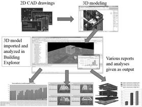

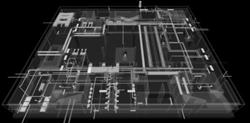
While the construction was underway, progress data was collected weekly from the site and the 4D simulation was updated. With this data progress became measurable, as well as the productivity of each subcontractor and each type of work. These analyses allowed far more accurate predictions of whether the deadline would be met or not, and what needed to be changed in order to stay on schedule. Because of the capability of generating multiple schedules based on very different methodologies, dozens of alternatives were made, and together with feedback and requests from the subcontractors the optimal one was chosen. Along with weekly progress reports, a plan for the following week was sent to the general contractor and subcontractors, telling what needed to be done in order to keep up with the schedule. It included resource quantities, material quantities and schedules for individual work items, and detailed perspective views of relevant parts of the project generated from the 3D model.
Building Explorer includes clash detection algorithms, downtime and standstills on the construction site were reduced to a minimum. The clashes were reviewed and solved on joint meeting s of all the involved parties, virtually, on computers, vastly improving the communication and reducing the cost of reworks and fixes on the construction site. The timeframe from document designing, to solving detected clashes, and finally submitting project documentation to the construction site was very short, sometimes lasting only 48 hours. This approach affected schedule too, since there were far less unplanned reworks.
An excellent example of this was in late February, when due to several problems in the construction process, the project fell one month behind schedule. Multiple 4D simulations, including different construction scenarios and methodologies, were developed, in order to compensate the fallback and return on schedule. With respect to the current productivities of subcontractors and the state of the construction site, adequate suggestions were proposed to both the investor and the general contractor. After accepting and applying the proposed measures, the setback was mitigated, returning the project on schedule.
Weekly reports were used to plan material procurements, and resource quantities, so that no excess resources resided on the site. Besides resource balancing, cost balancing was also achieved, to the benefit of both the investor and general contractor, allowing them to make payments for material and resources only when necessary. Precise cost information was accomplished combining the accurate quantities of the 3D model with the precise resource quantities and actual productivity from the schedule.
Finally, the control of quality was achieved through the 3D model itself – every element had a set of various documents associated to it, in the following order:
• Original, planned documentation
• Instructions for element usage and maintenance
• Pictures of the actual element, as -built, in all stages of construction
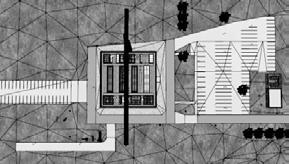

• Certificates, verifying the elements state from the on-site inspector
• Maintenance and investment plan
With both original and as-built documentation attached to construction elements, the quality of each is easily verified. With all as -built, maintenance and exploitation details, along with the 3D structure of the project, cost and schedule information, the final 6D model is created, called an exploitation model. This model is later extensively used for simulating building usage and facility maintenance.
In order to coordinate all aspects of construction and consulting services, a highly optimized system for exchanging information and project documents is mandatory. To solve this problem Bexel provided an in-house developed Document Management System. It was used as the centralized storage for all project documents, containing all up-to-date information, multiple revisions of documents, and role-based security
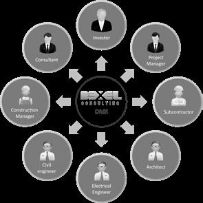
With all solutions implemented, several key advantages were achieved:
• Construction was completed 11 days before schedule, in spite of a one month delay;

• The contractors had a 3D model with detected clashes and a 4D simulation of the project during construction The model and simulation were reviewed on regular meetings with all stakeholders and used for planning work and avoiding unnecessary rework and redundant resources as well as improving construction speed;
• Various construction scenarios were considered for many parts of the project in different phases, and optimal ones were chosen;
• Around 1,600 clashes were detected and solved in design time, saving roughly $ 350 000;
• The project team had foreseen many possible delays and took action before they happened to keep the project on track;
• The investor was provided with planned vs. actual analysis, risk analysis and recommendations before actual problems arose, allowing him to make timely decisions;
• All solutions eventually led to an actual budget 5% lower than the planned one;
• After collecting and analyzing all resource quantities, actual productivities were calculated, and will be reused for better planning of future projects
The HyperCube, modest in size, included innovative technologies with a large number of complicated services and demanded high quality build. Thus, it is a great example of how VDC and BIM can be used to overcome various challenges, mainly meeting construction schedule deadlines, solving clashes virtually before they occur on site, improving build quality and minimizing construction costs. It serves investors and contractors alike.

[1] Bilal Succar “Building information modelling framework: A research and delivery foundation for industry stakeholders” . Automation in Construction, 18(3), 357-375, 2009.
[2] AGC, The Contractors' Guide to BIM Edition 2, Associated General Contractors of America, 2010
[3] G.D. Oberlender, Project Management for Engineering and Construction, McGraw-Hill, Inc., New York, N.Y., 1993.

Faculty of Civil and Geodetic Engineering
University of Ljubljana, Ljubljana, Slovenia
E-mail: 1tomo.cerovsek@fgg.uni-lj.si
Abstract The paper tries to explain the lifecycle of a BIM Model from as-design to Asbuilt that can be finally transformed into as-managed (i.e., BIM FM). The focus is on the BIM lifecycle: constructability issues, change management and MEP coordination. In a case study we present a large scale faculty project with brief description of the use of BIM, including practical use of BIM MEP coordination and gradual development of as-built BIM.
Keywords BIM lifecycle, MEP coordination, constructability study, as-design, as-built


There are many views that affect the way we perceive any technology and its benefits. Three important views include [1]: (1) organizational, (2) process and (3) technological view. These views may alter if we change the time window of observation, especially if this is the whole lifecycle.
The same way the LCA (Life-Cycle Analysis) was adopted for buildings, the BIM Model LCA can be used, especially in terms of support policy, process improvement and informed decision making. BIM LOD (Level of Development) provided valuable BIM management practise that defines content in the lifecycle of BIM. The paper focuses on different changes in the lifecycle of BIM (dark on Fig. 1).
The motivation for the exploration of the concept of the BIM Lifecycle is the potential of BIM to be used throughout the lifecycle of a building, on one side and throughout the lifecycle of business processes and professionals that have access rights to the BIM models, on the other side. However, legal issues related to the BIM are out of the scope of the paper.
The lifecycle of a BIM model [1] was already given by Gielingh’s seven lifecycle categories: as-required, as-designed, as-planned, as-built, as-used, as-altered and as-demolished model; a business process standpoint gives five types: requirement, design, production, commissioning and operation model; and a product-procurement standpoint gives four: asdesigned, as-ordered, as-delivered and as-owned. We give a brief overview of technical, semantic and organizational aspects on the lifecycle of BIM:
Technical. From the technical standpoint it is important to know how data is technically coded, delivered and consumed. From this standpoint the lifecycle of a BIM Model can be in one of the two stages [1]: (1) active, where CRUD (Create, Read, Update, Delete) and model management is an ongoing (live) process and (2) inactive, if only the storage, retrieval and metadata of BIM model data is used outside the scope of “authoring” project.
Semantic. Models differ in the levels of detail and complexity and may change over time. A reference to the physical, tangible appearance of a building from a time standpoint can be represented by the following three categories: ‘as-it-was’, ‘as-it-is’, or ‘as-to-be’. From the building process standpoint it is important to cover main phases: pre-construction, construction and post-construction with three corresponding BIM models, these are: as-designed, as-built and as-managed.
Organizational. From an organizational standpoint it is important to know how the need for information was formulated by providing answers to the following questions: what, when and where with three sub-questions how, where and why BIM content was developed. These would yield in a complete audit trail of BIM providing valuable information for the whole lifecycle. For example, we would be able to analyse and re-use model and its parts (e.g., the reuse of BIM parts from one model into another, knowing the background as well).
In terms of the context of the use of BIM in a project it is important to observe the lifecycle of BIM model in relation to the phase of the project and changing BIM technologies that are used for authoring and outside authoring environment by the downstream applications, while considering standardization (e.g., NBIMS, PAS, COBIE, AIA LOD specification).
The general approach to BIM Management should be in line with common management practices as defined by PMBOK (Project Management Book of Knowledge). The “BIM way” management may be translated using mapping in the Table 1. The main goal of BIM Management is to provide sufficient LOD to fulfil project information needs (on time). The success of BIM depends on participating individuals’ competency components [2]. The level of competencies of individuals and team shall assure the delivery of a trustworthy, high quality model BIM model matching used building technology.
PMBOK Stage BIM Equivalent Targeted Impact
Initiate BIM Project Brief Project information and BIM authorization
Plan BIM Execution Plan Uses, goals, objectives and collaboration BIM
Execute BIM Execution Protocol Coordination and resource management
Control BIM Quality Control Reduction of risks and progress control
Close BIM Review Archiving Review impact, lessons learned, FM use
Proper BIM management lead quantifiable benefits [3] (e.g., the quantity of RFIs, the percentage of change orders against overall contract costs and the percentage of actual duration/standard duration) and BIM costs measured in terms of construction and operation cost (e.g., percentage of BIM costs of A/E services against total costs of non-BIM and BIM scope awarded). The implicit impact of BIM, e.g., better communication, easier change management, higher quality of buildings, possible improvement of whole-building lifecycle and quality of living spaces that do not translate easily into monetary units.
The lifecycle of BIM starts with design (LOD 100) and shall gradually translate into BIM FM. Due to an iterative nature of a design process and the need to accommodate evolving client’s requirements, it is essential that BIM management supports the lifecycle of BIM. BIM shall function as a tool for Value Engineering that facilitates communication, propagates consistent changes and supports decision making in all phases of a building project. One of the most demanding tasks in the process of the lifecycle of BIM is MEP coordination.
Problems related to the MEP (Mechanical Electrical and Plumbing) coordination and conflicts between trades have been known for decades [5] as one of the most important and challenging in the construction in any new construction or existing complex building. MEP building systems represent from 25–40 % of the total project cost and often lead to delays and problems related to the limitations of available space and construction-phase (not designphase) coordination between different trades [6, 7].
The causes for the level of the MEP coordination problems depend on the complexity of MEP, which may be characterized by three criteria:
Architectural and structural complexity in terms of geometry and used technology
The (un)availability of space for the MEP building systems (e.g., lowered ceilings)
Number and complexity of the MEP routes, used materials, elements and equipment.
Some of the most important causes for delays and extra costs are [8]: a lack of ability to identify conflicts due to topological (line - based) 2D representation of routes resulting in a late identification of problems; rework needed to fix errors and conflicting issues, which often require redesign and extra on-site coordination with MEP Consultants, increased supervision to avoid conflicts between trade contractors, increased administration burden of more RFI (Requests for information) and frequent change orders and “install first” mentality. Some recent studies [8, 9] show the advancement of MEP coordination based on the actual as-built, location based methods, detailed specifications for each MEP duct/pipe element and equipment being installed. The overall process is supported by detailed algorithms that may be used to provide exact quantities and dimensions for all elements of MEP building systems, including job site delivery optimization.
A promising approach to the rapid development of accurate and always current as-built models, is via laser scanning, e.g., an automated approach to generate the as-built 3D pipeline model [8]. A successful implementation of the project must have well defined change management procedures.
Furthermore, a demanding technological project requires an interdisciplinary approach. Here, the coordination of MEP systems is one of the most challenging and demanding [5] where a set of recommendations were proposed that can be grouped into three categories:
The Architects and Engineers (A/E) must do a better job in coordinating their work. Systematic research on MEP coordination during the installation process lead to the conclusions [5]: MEP coordination process is a slow and it can become a critical path for systems installation. In the traditional design-bidbuild practice, still most frequent in many EU countries, the design is less coordinated compared to design-build. The success of coordination process highly depends on change management. There are two types of changes [10]: Direct changes: addition or deletion of works, revision to material specification, revision to project planning, change to site access and operation and contract duration Constructive changes: not recognized by the client as a change (e.g., changes to fix constructability)
b) Improved communication (two-way)
MEP coordination depends on the communication problems that may divided into:
Sender/Receiver: limited incentive, legal obligations, competences, misinterpretation, missing data on the production drawings.
Communication channel and the media: the effectiveness/efficiency of MEP coronation depends on used technological media
Noise and environment of communication: time, budget, stress, attitude issues in daily installation management
The lead discipline in MEP coordination, for instance mechanical, must inform the architect about space required for ductwork and piping during design and not during construction. The mechanical designer should be reminded to provide additional sections at the potential trouble spots. Also, the mechanical designer must recheck the motor sizes shown on the electrical drawings to ensure the motor sizes shown there agree with the mechanical drawings. Similarly, other lead disciplines must inform other disciplines that may be affected.
b) Improved quality control
The A/Es should be asked to provide a plan for quality check and its actual implementation to avoid these interdisciplinary problems. Huge amount of problems could be eliminated through the use of BIM based design and coordination. There are many ways to measure the success or failure of coordination, some of them were already listed in the introduction (e.g., reduced costs, change order, reduced rework).
The case study that is presented in the paper is based on the investment in new premises of the University of Ljubljana, Slovenia. The new campus project has three main buildings: Faculty of Chemistry and Chemical Technology (UL FKKT), Faculty of Computer and Information Science (UL FRI) and in the middle it has a crossing building X (Fig. 1).
The goal of the project was to establish conditions for encouraging and forming of more innovative and technologically advanced economy, which will also contribute to the opening of new, high added value employment possibilities.
The project aims to strengthen the cooperation between academia and industry. It shall promote joint ventures in the development of new high-tech technologies, organizations, design, marketing and products for large, middle and small enterprises.
The facilities will provide required infrastructure for more innovations, faster technological development of the economy in Slovenia and wider in the region. Besides being the largest project in the history of the University of Ljubljana, the project is also a significant contribution to the Slovenian economic growth. More general data at www.uni-lj.si.
Altogether there are 42,000 m2 of dedicated spaces. The total value of the project is 116.4 million EUR that includes the purchase of the plots, inception, design and preparation of detailed documentation, including acquisition of all necessary permits, construction and finishing work, purchase and installation of equipment, supervision, peer review and monitoring the project. The construction of the UL FKKT and the UL FRI is the largest project in the history of modern Slovenia receiving the EU ERDF grant for an educational infrastructure. The University acquired 88 million EUR of EU grant funding for the construction of the new premises.
The project is located within the inner ring of the Ljubljana (Fig. 2), near the city Zoo, next to the National Institute for Biology and in the vicinity of Technological Park. There are three buildings: two 4-storey UL FKKT, UL FRI and 3-storey building X.

Technological park (C) (by Google maps, 2013-10).
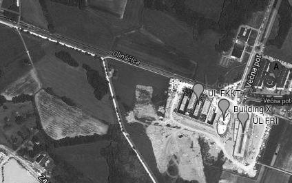
The location is on the soft soil, therefore, the substructure is made of driven piles (318 pcs. of diameter from 80 to 120 cm of length up to 20 meters). The UL FKKT (top view: E shape) with close to 180 labs and UL FRI (top view: rectangular shape 130 x 30 m) are made of over 60,000 m3 of cast-in-place concrete containing over 3,000 tons of reinforcement. The building X (top view: kidney shape) in the middle is made of 875 tons of steel. The most complex geometry has the building X, where each floor is rotated for about 3 % around a vertical axes, there are 64 circular columns - each under a different angle to the horizontal plane.
The repository of project documentation contains around 2,500 documents and drawings. Most of the AEC design was in 2D, except the connecting building X, which was, due to its complex geometry, designed by structural engineers (Elea IC) in 3D and shop drawings were generated from the model.
The selection of lead designer was based on a public architectural competition, which was completed in 2007. The winning architectural solution was designed by the architectural office 4M Engineering from Ljubljana. Each building was designed by a different architect, therefore, each building has its own style and, consequently, also different technical details. Architectural office had a contract with structural consultants, while MEP consultant had an independent contract.
At the time of writing, the project is still under construction. The project is complex by many criteria: there are three general contractors (Fig. 4) with complex organization, planned maximum number of workers on the site is more than 500 and buildings have 42.000 sq m with tens of kilometres of MEP systems, including process piping.
The central approach that supported the overall use of BIM on the project is the concept of coordination model (Figs. 5, 9) that is used throughout the project.
The activities related to the use of BIM may be summarized with the following:
Detailed project documentation review and development of project information
Development of BIM Brief, BIM Plan with BIM team with competent members, prioritization and definition of basic standards along with the intended use
Modelling of three separated models (architectural, structural and MEP models were developed independently)
Constructability Study published as paper reports and also on the project portal that supported change management and review
The project MEP systems fall into category of complex MEP systems by the defined criteria:
The building in the middle is very complex ad described in sub-section b) above
There is only 75 cm of total space above the lowered ceilings for MEP Building Systems. The designed HVAC systems were of immense dimensions (e.g., width up to 210 cm)
MEP Building System includes: three types of gravity systems and a very complex process piping system, which include gas supply for close to 180 laboratories
2D layouts of HVAC systems include basic dimensions (shape types, dimensions and distances from the floor or from the ceiling), routing is determined topologically using lines, however, routes on the production drawings have no horizontal dimensions (read: distances from the walls). This gives many open options for different interpretation that require coordination issues.
BIM Based Coordination of Construction and development of As-built models for later use in BIM FM
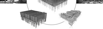

BIM use covered: site analysis, quantity take off, 3D coordination, constructability studies, visualization, model based scheduling, 4D simulation, virtual mock-up, energy analysis, part of the model was also used for the steel production using CNC, gradual condition modelling, in part for lighting analysis and for the technological project (i.e., labs) from end user requirements collection to implementation catalogues. One of the goals of the use of BIM in the project is to support the whole lifecycle of BIM and assure model relevancy for the duration of the project. This requires constant updates of the BIM model that slowly becomes as-built model.
Some main benefits of the use of BIM were: the Constructability Study that identified close to 400 inconsistencies and lead to substantial changes and redesign of project documentation, easier execution of technological project and MEP coordination and change management. Detailed description of the latter is given in the next section.
The overall BIM based coordination of MEP building systems is illustrated on Fig. 6 with an IDEF0 diagram. There are five main activities:
MEP Contractor and its MEP Subcontractors reviewed Building Systems. The review of Building systems included: detailed review of project documentation that was handed over to the lead MEP Contractor, review of additional project documentation due to changes in technological equipment, review of Constructability Studies and Coordination BIM Models (Fig. 9).
Based on the detailed review of building systems, MEP Contractors and Sub-contractors proposed changes. The reasons for recommended changes were: missing dimensions, insufficient space for installation and maintenance, uncoordinated building systems and “install-first” mentality. The routes on the production drawings don’t have exact locations, while elements have dimensions, but are without dimensions of insulation and sizes of motors.
The approvals were of two types depending on the extent of changes, these are: minor changes and major changes. Minor changes are changes that do
not affect the main routes of the systems and architectural elements, while major changes cover the rest. Major changes had to be confirmed by the Lead designer (architect) and client representative and not only by the lead MEP Consultant.
The lead MEP contractor managed all the speciality MEP sub-contractors and organization of the work. In the support for the coordination process among speciality MEP sub-contractors, BIM was used on the construction site, which allowed them to see interactions between different MEP systems, as well as exact routing in the z direction, which is not visible from the 2D drawing.
In addition we have prepared paper versions of 3D views for the MEP installers with marked references to additional cross sections (Fig 7.).
The inspection of Installed Building System is performed by project supervisor to assure that routes are as-designed and installed elements meet requirements. In addition BIM team used photo, video on regular intervals (usually 14 days) to gradually develop as-built using Archicad MEP Modeller. All differences between as-designed and as-built model were systematically documented during review. In laboratories we also used virtual reality and laser scanning to determine as-design asbuilt differences (Fig. 8).


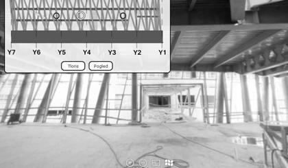
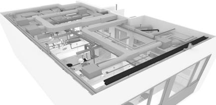


The importance of coordination and communication of project information is (in general) underestimated. The major cause for insufficient flow of information and, consequently, hampered collaboration is in the tight schedule and partly also due to traditional management of design process and graphical (topological) representations. This is especially important in demanding technological projects. For the successful implementation of a BIM project there are three critical issues that must be addressed:
Any BIM project depends on a team, planning, execution and management of the BIM process and involved stakeholders.
The credibility of the model is essential for a successful implementation of a BIM in a construction project
Multiple media (models, web and paper) based on BIM can make the most for the construction project
The following conclusions can be made:
MEP Coordination is the most demanding part of building systems in the construction of a complex technological project
MEP BIM can significantly improve coordination and reduce installation time
A successful MEP coordination requires detailed insight into MEP technology and high quality, up-to-date model with crucial data, where exact geometry with schematic representation is more important than a very high level of development.
Using MEP BIM a significant improvement in the communication can be achieved with proper use of 3D project documentation and traditional 2D representations.
According to the statement of Lead MEP Contractor the installation of the MEP Building Systems would not have been possible within given schedule without presented approach.
Active participation and collaboration of the Lead designer, Architectural office 4M Engineering, the team of Structural Engineers from Elea IC Ljubljana, Lead MEP Consultant, IBE, d.d. and Lead MEP Contractor, IMP d.d., laser scanning experts 3D Biro is gratefully acknowledged. The BIM approach was executed by CERTUS 5D Consultants, which is led by the author and operates as part of the Ljubljana University Technology Transfer.
[1] _______. “A review and outlook for a 'Building Information Model' (BIM): a multi-standpoint framework for technological development”. Advanced engineering informatics, 25 (2) 224244, 2011.
[2] B Succar, W Sher A Williams. “An integrated approach to BIM competency assessment, acquisition and application”. Automation in Construction, 25(2013) 174-189, 2013.
[3] W Hughes, JR Murdoch. “Roles in construction projects: analysis and terminology”. Construction Industry Publications, pp 176, ISBN 1852638982, Birmingham, UK, 2001.
[4] K Barlish and K Sullivan. “How to measure the benefits of BIM – A case study approach”. Auto. in Construction, 24(2012) 149-159, 2012.
[5] S Sehgal. Design alert from procats (proactive claims analysis and tracking system) Design Allert, Standards service, U.S. Department of Veterans Affairs, Office of Facilities Management, Washington, United States, 1994.
[6] CB Tatum and T Korman, “MEP Coordination in Building and Industrial Projects”. CIFE Working Paper #54, Center for Integrated Faclities Management, Stanford University, 1999.
[7] HP Tserng, YL Yin, EJ Jaselskis, W-C Hung, YC Lin. “Modularization & assembly algorithm for efficient MEP construction”. Automation in Construction, 20(7) 837-863, 2011.
[8] A Khanzode, M Fischer M, D Reed. “Benefits and lessons learned of implementing building virtual design and construction (VDC) technologies for coordination of MEP systems on a large healthcare project”. ITcon 13(2008) 324-342, 2008.
[9] J Lee, H Son, C Kim, C Kim. “Skeleton-based 3D reconstruction of as-built pipelines from laser-scan data”. Automation in Construction, 35(2012), p 149-159, Elsevier, 2013.
[10] Oracle “Change Management Best Practicesfor the Engineering and Construction Industry”. Pp 31, 2009.
[11] K Keesoo and BC Paulson Jr. “Multi-Agent Distributed Coordination of Project Schedule Changes”. Comp.-Aided Civil & Infrastructure Engineering, 35(2012) 412-425, 2013.
[12] R Eacie, M Browne, H Odeyinka, C McKeown, S. McNiff “BIM implementation throughout the UK const. project lifecycle: An analysis”. Automation in Construction, 36(2013), p 145-151, 2013.