4 minute read
MIT RESEARCHER TESTS INNOVATIVE STEEL-CONCRETE BEAM


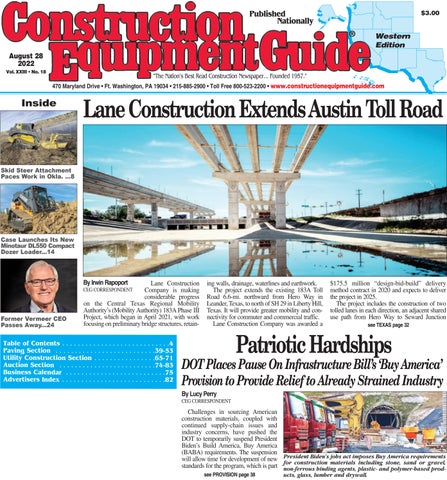
Photo courtesy of the University of Arkansas website Designed to carry 8,500 lbs., the beam eventually cracked after 12,000 lbs. of load were added.
Photo courtesy of the University of Arkansas website (L-R) are Mohamed Ismail, Emily Baker and Bette Poblete at the U of A Civil Engineering Research and Education Center.
On a recent July day, representatives from the University of Arkansas (UA) and the Massachusetts Institute of Technology (MIT) gathered at the Harvell Civil Engineering Research and Education Center on the UA campus in Fayetteville to conduct a stress test on a concrete beam.
Now, such tests typically do not attract many onlookers, but this demonstration was meant to showcase a collaborative new approach to beam design and optimization.
The man responsible for the beam’s design was Mohamed Ismail, a Ph.D. student in building technology at MIT — a discipline existing at the intersection of architecture and engineering. He was on hand to witness the crushing test in person and seemed vaguely nervous that the beam might not perform as expected — a feeling heightened by the unusual degree of attention the stress test was receiving.
The fruits of research are not always immediately clear, but the nature of the test — hydraulic press versus concrete beam — brought out the various colleges’ social media staff, who recognized strong visual content when they saw it, according to a recent news article on the UA website. Goal Is to Become More Efficient With Less
Among Ismail’s research interests is increasing the structural efficiency of building materials. In the case of concrete beams, that means minimizing the amount of concrete and steel used, including removing concrete from where it is not needed, and retaining it where it is. This resulted in his beam having a flat top but a base that curved in unanticipated ways.
He estimated that the beam in question contained 40 percent less embodied carbon — the amount of carbon burned to produce the concrete and steel used in the beam — than standard rectangular beams.
This is important for reasons of both sustainability and economy, Ismail noted, as he has his eye on the developing world, where urban growth is expected to surge.
“You’re looking at places where there’s going to be a need for high density construction,” he explained. “So that means going up, going vertical and doing it safely. And, really, the only material that’s widely available and accessible to most of those regions is concrete, so concrete’s expected to be the number one material we use today. And it’s expected to just go up in use because we really haven’t found [any other] material that’s able to meet demands and still be safe.”
Bette Poblete, a graduate research assistant in civil engineering at UA who was conducting the stress test, noted it was one of the more interesting beam shapes she had encountered.
“Ordinarily, we test rectangular beams,” she said. “There are a couple reasons we do this: it simplifies some of our calculations and makes the construction more straightforward. In terms of calculations, we rely on the geometric dimensions to help predict the strength of the beams. Before we test any member, we calculate the predicted load at which it will fail. Then, we’ll compare our predicted loads to the actual loads. Since we use simpler shapes ordinarily, it makes the entire process easier.”
In terms of testing Ismail’s beam, Poblete added, “This beam was longer than we usually test, so getting it into our load frame posed a fun challenge. We ended up using our crane and forklift simultaneously to place it on our supports. Also, since the beam was trapezoidal at the ends, we had to be especially careful not to chip the corners.” Unique Geometric Shaping Techniques
Although there are undoubtedly similar testing facilities closer to Boston, where Ismail lives and is a doctoral student at arguably the best research university in the world, he came to UA to crush his beam for two reasons: Emily Baker and Edmund Harriss.
Baker is both an Arkansas graduate and a current assistant professor in the Fay Jones School of Architecture and Design, while Harriss is a clinical assistant professor in math in the university’s Fulbright College of Arts and Sciences.
Together, they have been working on what they have dubbed the “Zip-Form” system. It arose out of an art project Harriss created through the Honors College, which ultimately became the 12-ft.-tall Curvahedra sculpture outside UA’s Gearhart Hall — a spherical structure composed of a few curving steel strands.
Harriss, whose primary work is in geometry, also holds an appointment in the School of Art. His stated desire is “to put mathematics in a playful, choice-driven space where people can play with or appreciate mathematics through art and sculpture.”
When he needed someone who could help fabricate the shapes he was dreaming up, using complex geometry, he reached out to Baker for help.
“I am deeply interested in exploring and innovating new ways of making physical objects and buildings,” Baker explained.
As such, making Harriss’ sculpture a reality posed a fun challenge for her. She ultimately created a jig, or clamping setup, to allow flat sections to be successfully attached, or “zipped,” into curving steel forms. This method, paired with Harriss’ computational formulations, became the basis for their Zip-Form construction system, producing highly accurate 3D curves with simplified fabrication techniques.
The efficient and economical software and manufacturing process proved so novel that the university, through its Technology Ventures office, later filed a provisional patent. UA System Creates Formwork for Test Beam
While the Zip-Form system was clearly innovative and could produce pleasing structures, Baker and Harriss knew there were more practical applications.