Utility Cuts in Concrete Pavements

Page 1

Utility Cuts in Concrete Pavements nnnnnnnnn Concrete pavements have long been recognized as clean, smooth riding, strong, and durable, and properly designed and constructed concrete pavements should provide several decades of zero- to low-maintenance service. At times, it is necessary to cut trenches in some concrete pavements, particularly in urban areas, in order to repair or install utilities such as sewers, drainage structures, water mains, gas mains and service lines, telecommunication lines, and power conduits. Unless the cost of trenchless methods that do not disturb the pavement is justified, the pavement must be opened up, the utility installed or repaired, and the pavement restored using a utility cut restoration. If these operations are carried out properly (see Appendix 1 for the step-by-step process of making a utility cut in a concrete pavement), there will be minimal impact on the pavement's functional serviceability, ride quality, and lifespan. Experience has shown that it is best to repair or restore concrete pavements with concrete. Proper utility cut restorations, constructed even with the surrounding pavement, provide a smooth transition that can withstand traffic loads without future settlement. Flowable backfill, a material that solidifies in about four hours, and/or a fast-setting concrete mixture that can carry traffic in four hours or less can be specified; precast concrete panels might even be used to further expedite the most timesensitive utility cut restorations. The purpose of this publication is to provide guidance for the city engineer, public works supervisor, utility foreman, or contractor who must plan or carry out a utility cut and the subsequent utility cut restoration. This publication describes simple design and construction techniques, which usually do not involve any specialized equipment, contractors, or materials; these techniques apply primarily to utility cut restorations in light-truck-traffic roadways, such as residential and collector streets. Exceptions to these techniques for specialty situations, such as utility cuts in overlays, are included in the "Other Design Considerations" section.

n Planning the Utility Cut Location, Size, and Shape The first step is to plan the location, size, and shape of the utility cut after the location of the new or existing utility is identified.

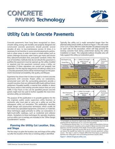
Typically, the utility cut is made somewhat longer than the planned utility trench width, as shown in Figure 1. This will create a 6 to 12 in. (150 to 300 mm) wide shoulder of subbase/subgrade on each side of the excavation, which will help prevent the existing concrete from being undermined during the utility installation or repair. This subgrade/subbase shoulder also will help support the utility cut restoration patch. Full-Depth Cut* Dowel Bar Existing Pavement

Utility Cut Length Utility Trench Width Restored Concrete Pavement

6 – 12 in. (150 – 300 mm) of Compacted Subgrade/Subbase

Existing Transverse Joint* Existing Pavement 6 – 12 in. (150 – 300 mm) of Compacted Subgrade/Subbase

Utility

Flowable Backfill or Compacted Granular Material***

Concrete Pavement with Thickness > 7 in. (175 mm) New Transverse Joint**

Utility Cut Length Utility Trench Width

Existing Pavement

Restored Concrete Pavement

6 – 12 in. (150 – 300 mm) of Compacted Subgrade/Subbase

Existing Transverse Joint** Existing Pavement 6 – 12 in. (150 – 300 mm) of Compacted Subgrade/Subbase

Utility

Flowable Backfill or Compacted Granular Material***

Concrete Pavement with Thickness < 7 in. (175 mm) * A full-depth cut should be made at any utility cut boundary that is not an existing joint for thicknesses of 7 in. (175 mm) and greater. ** For pavements thinner than 7 in. (175 mm), utility cut boundaries that are not at an existing joint should be cut to a depth of about one third of the slab thickness and the remainder of the depth removed with a jackhammer. *** Some agencies have had success with up to a 2 ft (0.6 m) layer of natural soil above the backfill but below the restored concrete pavement surface course. This layer is used to mitigate differential frost heave or settlement between the utility patch and surrounding pavement (SUDAS 2005).

Figure 1. Detail of typical utility cuts. 1 ©2009 American Concrete Pavement Association


Some engineers like to specify removal of a little more depth at the subbase/subgrade shoulders so that the concrete patch will be 1 to 2 in. (25 to 50 mm) thicker than the surrounding pavement, slightly enhancing the structural capacity of the restored concrete pavement section; such recommendations should be weighed against the anticipated remaining service life of the surrounding pavement because the utility cut should not be engineered to last longer than the existing pavement. The layout of the section depends on the location of the new or existing utility relative to existing pavement edges and joints, and whether a square/rectangular or circular utility cut will be made. As mentioned, this publication focuses on utility cuts and the subsequent pavement restoration; more general details on managing utility cuts and their locations, permits, etc., are available elsewhere (AASHTO 2005; APWA 1997; FHWA 1993, 1996; Kansas LTAP 2007). Any utility cut edge in a slab’s interior should be located at least 2 ft (0.6 m) away from any joints or pavement edges. If it is determined that a cut would occur in this 2-ft (0.6-m) zone, extend the utility cut boundary to the joint or edge. This may require changing any circular utility cuts to square or rectangular cuts. This extension of the utility cut to nearby pavement joints or edges is done to avoid leaving small sections near joints or edges that may crack and break under traffic loads. It is important that the edges of a utility cut line up as closely as possible with transverse and longitudinal joints in the existing pavement whenever possible. If this is not done, "sympathy cracking" may form, extending from the pre-existing joints. Also, if at least one edge of the utility cut can be located to coincide with an existing joint, the amount of saw cutting may be minimized.

Good Practice Utility Cut Length Chipped Edges Taper Inward Utility Trench Width

Poor Practice Utility Cut Length Undercut Spall Utility Trench Width

No Rim

Figure 2. Examples of good and bad chipped faces and subgrade/subbase rims for a utility cut in a concrete pavement thinner than 7 in. (175 mm). Plan View Existing Joint

Full-Depth Buffer Cuts

Existing Joint Cut This Boundary to Full-Depth if Slab is 7 in. (175 mm) or Thicker and to OneThird Depth if Less Than 7 in. (175 mm)

Shoulder Isolation Cut

Profile View Reduced Normal Reduced Break Break Break Energy Energy Energy

If isolation or expansion joints are present in the existing pavement within the confines of the utility cut area, these joints should be re-constructed at the same location(s).

n Creating the Utility Cut

6 - 12 in. (150 - 300 mm) of Compacted Subbase

Existing Pavement

Existing Pavement Utility Cut Length

Making the Necessary Cut(s) in the Concrete Slab For utility cuts in concrete pavements thinner than 7 in. (175 mm), dowel bars can be excluded from the transverse joints as long as sufficient aggregate interlock is provided for load transfer. To create such a condition, the existing pavement should be cut with a concrete saw to a depth of about one-third of the slab thickness. The remainder of the slab depth will be chipped away during the section removal, resulting in a roughened, slightly-tapering-inward face (Figure 2). Any utility cut boundaries that are at existing joints might utilize any existing dowel bars or tiebars (noting that tiebars are only necessary in longitudinal joints in utility cut restorations longer than one panel), requiring the concrete around such embedded steel to be removed carefully. To easily accomplish this, buffer cuts may be made some distance away from the joint boundaries so that the bulk of the utility cut area can be removed using normal break energy and the sensitive boundary areas removed using reduced break energy (Figure 3).

2

Figure 3. Buffer cuts for protecting the utility cut perimeter. If the utility cut is to be made in a concrete pavement that is 7 in. (175 mm) or thicker, dowel bars are required for load transfer, rendering aggregate interlock unnecessary. As such, full-depth sawcuts can be made at any utility cut boundary that is not at an existing joint to ease removal. Depending on the concrete removal method and if any boundaries of the utility cut are at existing joints, buffer cuts might also be used to protect the utility cut perimeters from surface spalling and/or undercutting of the existing slab during removal of the section. When making a rectangular or square utility cut, the cuts should be perpendicular, straight lines at the edge of the utility cut (Figure 4); round utility cuts are made through the full-depth of the concrete, similar to typical coring operation. Saw cuts are preferable to line drilling because they create a clean edge and will minimize the potential for long-term spalling around the utility cut boundaries.


If the pavement is thinner than 7 in. (175 mm), special care should be taken to obtain a slightly-tapering-inward cut for all transverse joints that are not at existing joints (see Figure 2). A rough, irregular face below the saw cut is desirable to promote load transfer across the transverse joints in these thin pavements. Regardless, the method of breaking the removal section should not damage the adjacent pavement or overbreak/undercut the slab bottom resulting in a cone or pyramid-shaped patch with poor load transfer and an increased potential for punchout of the utility cut restoration section. Figure 4. Diamond-bladed saw making perpendicular, straight cuts around the perimeter of a utility cut.

Figure 5. A pressure relief cut made using a carbide toothed wheel saw (kerf saw) down the middle of a utility cut to aid in removal of the section. During hot weather, the sawing equipment may bind during initial sawing, so it may be helpful to perform sawing at night when the temperatures are lower and the slabs are contracted (also when the traffic volume is lower). Another solution is to provide one or more transverse sawcuts in the area to be removed, similar to those made for buffer cuts (see Figure 3). If the saws continue to bind, yet another solution, if the contractor has the equipment readily available, is to use a carbide toothed wheel saw (or kerf saw) to provide a pressure relief cut within the patch area prior to boundary sawing (Figure 5). Such pressure relief cuts might also be used to ease breaking and removal of the concrete in the utility restoration area (Figure 6).

An alternate method of removing the concrete is the lift-out method, in which full or partial slabs are lifted out of place. After the area to be removed is isolated by full-depth saw cuts, holes are drilled through the slab and fitted with lift pins. The slab is then lifted and removed in one or more pieces by some type of heavy equipment (e.g., a backhoe or front-end loader) with a chain attached to the lift pins (Figure 7). Alternatively, a claw-like attachment that slides beneath the concrete slab and grabs it before lifting may be used (Figure 8). Regardless of which lift-out method is used, care should be taken to lift out the slab(s) as vertically as possible to prevent the slab from binding and spalling the adjacent pavement. Because both lift out methods require full-depth sawcuts around the perimeter of the utility cuts, it makes this method the ideal, quickest way to remove utility cut sections in pavements that are 7 in. (175 mm) or thicker. The lift-out method also is the preferred removal method for circular utility cuts because it often allows for the intact core to be retained and replaced as a pseudo-precast slab section. If completed correctly, both lift-out operations leave a smooth, undamaged joint face. Although both lift-out methods typically are faster than the breakup and clean-out methods, the lift-out methods require some special equipment.

Removing the Concrete Removal procedures should not spall or crack adjacent concrete slabs. If they do, the utility cut restoration area might need to be expanded to ensure that the boundary is free of major surface defects. The concrete in the removal section typically is removed using the breakup and cleanout method. This is normally accomplished using a jackhammer or, for larger areas, a pavement breaker to break the slab(s), followed by removal of the pieces using a backhoe. Breakup should begin in the center of the removal area using normal break energy and, as the breakout operation nears the saw-cut boundary of the utility cut area, a reduced breaking energy, which might include switching to a lighter, hand-held jackhammer (see Figure 6).

Figure 6. Breakup of a utility cut area in a concrete pavement thinner than 7 in. (175 mm) after sawing the perimeter to a depth of about one-third of the slab thickness and making two transverse full-depth kerf cuts several inches from the transverse boundaries (note the remaining slab with kerf cuts in the background) to further aid in removal of the section. Also note that the saw-cut area is being removed with light jackhammers to obtain a slightlytapering-inward joint face on the transverse joints, without undercutting the slab.

3


n Preparing the Utility Cut Area

Figure 7. Partial slab removal using a lift-pin and chain lift-out method with a front end loader.

Reconstructing a subgrade/subbase and the subsequent installation of any necessary dowel bars or tiebars are the two primary keys to proper preparation of the utility cut area. The subgrade/subbase might be backfilled and compacted with native or borrow material (possibly containing recycled concrete aggregate (RCA)), or the area might be filled with a flowable backfill (again potentially utilizing RCA). Dowel bars are not necessary for utility cut restorations in pavements thinner than 7 in. (175 mm). If the pavement thickness is 7 in. (175 mm) or greater, however, dowels must be drilled and installed into the existing adjacent pavement at transverse joints along the boundary of the utility cut and dowel baskets must be installed at any transverse joints in the utility cut if it is longer than one slab. Tiebars should be included in longitudinal joints that abut existing concrete pavements (and in interior longitudinal joints) in portions of the utility cut restoration area that are longer than one slab and a bond breaker might be used in such longitudinal joints in sections where the joint is less than one slab long. As noted, it may be desirable to construct the utility cut concrete patch 1 to 2 in. (25 to 50 mm) thicker than the existing concrete for extra structural capacity of the restored concrete pavement structure, requiring slightly more subgrade/subbase to be removed between the perimeter of the utility cut trench and the utility cut; this should be done as part of the preparation of the utility cut area so that this lower elevation can be referenced when placing the backfill.

Figure 8. Partial slab removal using a clawed hook lift-out method.

Excavating the Subbase and/or Subgrade After the concrete has been broken and removed, the excavation is made to the utility or fixture that is to be replaced or repaired or to the depth necessary for the installation of the new utility. This may be done using a backhoe or skid steer loader, by hand, using a specialized vacuum, or by any other acceptable means. The need for shoring to prevent cave-ins of the trench will depend upon the type of subgrade soil, its condition at the time of excavation, and the depth of the utility trench. The contractor must have a good knowledge of the soils under the pavement and make this determination based on the current local and federal specifications or regulations governing excavating techniques.

n Repairing/Upgrading or Installing the Utility The utility is repaired or upgraded upon excavation, or a new utility is installed, using the appropriate procedures.

4

Some engineers recommend two additional cuts at the transverse boundaries of the utility cut area approximately 6 to 12 in. (150 to 300 mm) beyond the limits of the excavation after the utility cut trench has been backfilled/compacted (NCPTC 2008). This provides shouldering if sloughing of the trench has occurred during utility installation/repair. Such a precaution provides an even larger area of well-compacted subgrade/subbase to better ensure that the ends of the utility cut repair are supported. If done, the additional boundary cut(s) and the necessary hand-held jackhammer work should be performed prior to drilling any holes in the adjacent pavement for dowel bars. If a thickened slab is used in this scenario, removal of the top 1 to 2 in. (25 to 50 mm) of subgrade/subbase would be necessary prior to installation of dowel bars to ensure that the thickened slab is constructed to the boundaries of the utility cut area.

Backfilling with Granular Material and Compacting Settlement of utility cut restorations in pavements is a prevalent problem that can be avoided by careful construction and inspection during backfilling operations. While concrete is more capable of bridging a slight settlement than other paving materials, it is, nonetheless, wise to pay particular attention to the backfill specifications and construction procedures. When backfilling a utility trench, every attempt should be made to achieve adequate compaction of the backfill material so that it will not settle when in service. In the past, this often involved backfilling with previously removed material and tamping this material in 6-in. (150-mm) lifts at the proper moisture content and density. However, proper compaction of silt-clay soils in a utility cut trench is difficult, especially during wet weather.


Today, many public works engineers prefer removing all finegrained soil at the time of excavation and replacing it with cement-treated sand/soil or a select granular material. If used, select granular material must be free of frozen lumps and rocks larger than 4 in. (100 mm) in diameter. As with any un- or partially-stabilized backfill material, adequate compaction (95% of density as determined by ASTM D698/AASHTO T99) is critical to prevent later settlement. A cement-treated sand or soil will usually pay dividends to both the contractor and the municipality by ensuring higher, more uniform support, further preventing future settlement of the patch. The amount of cement used in such compacted mixtures should be only enough to "cake" the material rather than to produce a hardened soil-cement. Soils treated with lime or any other acceptable soil stabilizing material also may be used and should be compacted in layers at the proper moisture content.

Because flowable backfill is a self-leveling, flowable material, it can be poured into the utility trench, requiring no compaction, as shown in Figure 10. The trench is filled with the flowable material up to the level where the bottom of the new concrete surface course will be constructed. Typically, the material solidifies sufficiently to support loads or have the concrete surface course placed in about 4 hours. If the utility is not filled with fluid or is not neutrally buoyant relative to the flowable fill, it might be necessary to either secure the utility against possible floating due to buoyancy of the empty pipe or place the flowable fill in two layers: the first layer filling the trench up to the bottom of the pipe and the second layer, placed only after the first has set up, filling the rest of the utility trench. Alternatively, the utility can be bedded in a granular material, rather than flowable fill, up to at least half of the pipe depth.

Depending on the duration between compaction of the subgrade/subbase and the time when the concrete is going to be placed, it might be necessary to recompact the subgrade/subbase immediately prior to placement of the new concrete surface course (Figure 9).

Placing Flowable Backfill Flowable backfill is an ideal alternative to subgrade/subbase reconstruction for utility cuts. Flowable backfill is a low-strength, self leveling material made with cement, supplementary cementitious materials (SCMs; e.g., fly ash, slag cement, silica fume, etc.), sand (possibly fine RCA), and water that easily flows and fills the utility cut area, then hardens. Because it is designed not to become too hard, it is easy to remove later but, because it is so flowable, it requires some means of containment while it sets up. In addition to its fast setup time—usually within a few hours— flowable backfill has many advantages over compacted soil and granular backfills. Flowable backfill, available from ready mixed concrete plants in most locations, hardens to a degree that precludes any future trench settlement.

Figure 9. Recompaction of backfill immediately prior to placement of the new concrete surface course. Note that all other necessary preparation work has been completed, such as the dowel bars already having been drilled and installed.

Many terms are presently used to describe this type of backfill material: flowable fill, unshrinkable fill, controlled-density fill, flowable mortar, and various trade names. Controlled LowStrength Materials (CLSM) is the technical general term that emerged through ACI Committee 229 (ACI 1999), although the term flowable backfill tends to still be more commonly used. Flowable backfill has the advantage of being a standard, wellcontrolled material, mixed at a plant, transported to the site in a ready mix truck, or, on small jobs, delivered dry to a mobile mixer. In its application for backfill, the material is designed to have a very low strength compared to conventional concrete. A typical flowable backfill mixture consists of about 60 lb/yd3 (35 kg/m3) of cementitious materials and fine and coarse aggregate, with a slump up to about 8 in. (200 mm). A minimum strength of 10 psi (0.07 MPa) at 24 hours typically is required and the 28-day compressive strength specification typically is in the range of 50 to 100 psi (0.35 to 0.70 MPa); this ensures that, if necessary, it can be easily removed later using normal excavation tools and equipment. As such, it is important not to use too much cement or SCMs so long-term strength gain does not become excessive.

Figure 10. Placement of flowable backfill in a utility cut. Note that the flowable material is self-leveling, with the top of the backfill being placed to the base of the existing adjacent concrete slab [Photo courtesy of the Cincinnati Ready-Mix Concrete Company].

5


Use of flowable backfill along with high early strength concrete patches or precast concrete panels—discussed later—becomes important where there is a need to restore the pavement quickly to minimize traffic disruption. The extra cost for the material, compared to compacted backfill, is offset by the fact that it eliminates the costs for compaction and labor, reduces the manpower required for close inspection of the backfill operation, requires less trench width, and reduces the time and cost for traffic control and public protection measures.

The number of dowel bars required across the width of a fulldepth repair such as a utility cut restoration may vary. Some specifications require three, four, or even five dowels per wheelpath while others might require dowel bars at 12 in. (300 mm) on-center across the entire lane width. Different sizes of dowels should be specified for different pavement thicknesses (Table 1). The necessary minimum length of a dowel for a utility cut restoration is 14 in. (350 mm), although stock bars sized in the 15 to 18 in. (375 to 450 mm) range typically are used.

The performance of flowable backfill has generally exceeded that of compacted backfills with minimal problems due to settlement, frost action, or localized zones of increased stiffness. It has been used extensively in the U.S. and Canada since the 1970s.

Dowels in transverse borders of the utility cut are installed in holes drilled into the existing pavement. If possible, a gang drill should be used because of its ability to drill two or more holes simultaneously while maintaining proper alignment (Figure 11). The frame of a gang drill rig references the surface of the existing concrete pavement to hold the drills at the proper height and prevent the drill bits from wandering. If necessary, however, hand-held concrete drills might be used but special care should be taken to ensure that the drilled holes are within the acceptable tolerances. The depth of the holes should be approximately one-half the length of the dowel bar. Hole diameters exceeding the bar diameter are necessary to ease installation (see Table 1).

Installing Necessary Embedded Steel (Dowel Bars and Tiebars) It is crucial that all necessary subgrade/subbase and/or backfill compaction is completed prior to installing any dowel bars or tiebars because once the dowel bars and/or tiebars are installed it will be difficult to maneuver compaction equipment around them at the edges of the utility cut area. Load transfer is the ability of a utility cut restoration section to transfer part of its load to the adjacent concrete. Re-establishing load transfer across any transverse joint on the perimeter of a utility cut is one of the most critical factors affecting long-term performance of the section. Good load transfer reduces the stresses on the patch and prevents it from rocking and moving. For utility cut restorations in pavements thinner than 7 in. (175 mm), it is possible to obtain sufficient long-term load transfer with just aggregate interlock. Aggregate interlock load transfer is derived from the interlocking action between the roughened face of the in-place concrete and the face of the cast-in-place patch. As discussed, to create the roughened face, the crew removes the existing concrete along the transverse boundaries of the utility cut with a light pneumatic hammer to create a roughed, slightly-tapering-inward edge. If a concrete pavement thinner than 7 in. (175 mm) included dowels in the original design then dowels might be included as part of the utility cut repair but such recommendations should be weighed against the anticipated remaining service life of the surrounding pavement because the utility cut should not be engineered to last longer than the existing pavement.

Table 1. Dowel Size Recommendations for Utility Cut Restorations in Jointed Concrete Pavements Adjacent Pavement Thickness, in. (mm)

Dowel Diameter, in. (mm)

Drilled Hole Diameter, in. (mm) Grout

Epoxy

≤ 7 (≤ 175)

No Dowel

-

-

7 to 8 (175 to 200)

1.0 (25)

1.2 (30)

1.08 (27)

8 to 9.5 (200 to 240)*

1.25 (32)

1.45 (37)

1.33 (34)

10+ (250+)

1.5 (38)

1.7 (43)

1.58 (40)

* 1.5 in. (38 mm) diameter dowel bars, with the appropriate drill hole diameter, might instead be used in 8 to 9.5 in. (200 to 240 mm) thick utility cut restorations if more cost effective.

For utility cut restorations in pavements 7 in. (175 mm) or thicker, load transfer typically is best achieved by a sufficient size and number of properly installed dowel bars. Dowel bars are smooth, round bars that extend from one side of a joint to the other, transferring the load across the joint. Dowels improve pavement performance by: n Helping maintain the alignment of adjoining slabs. n Providing load transfer across joints, while at the same time allowing the joint to open and close as the surrounding pavement expands and contracts in response to temperature and moisture changes. n Limiting or reducing stresses that result from loads on the pavement.

6

Figure 11. A gang drill, used to drill multiple dowel bar or tiebar holes simultaneously.


The first step in installing dowel bars is to place grout (cementitious or epoxy) into the back of each hole (Figure 12). This ensures that the material flows out around each bar, fully encasing it. Do not coat one end of the bar with grout or epoxy and then insert the bar into the hole – the air pressure inside the hole will force the grouting material back out of the hole, leaving a void around the bar. The end of the bar that extends into the utility cut area should have a bond breaker applied to it to prevent bonding with the patch material. This bond breaker may be applied by the manufacturer or may be field-applied. If the repair is large enough to require transverse joints in the interior of the repair area, a contraction joint with dowels is necessary in pavements that are 7 in. (175 mm) or thicker; these dowels are installed using dowel baskets. Deformed tiebars have surface ridges that provide a locking anchorage when embedded in concrete. In contrast to dowel bars, tiebars are not designed to assist with load transfer but, rather, are designed to prevent opening of longitudinal joints at the utility cut/existing pavement interface or within the utility cut. Sections of a utility cut restoration that are longer than one slab, or utility cuts in pavements that have tiebars, should include tiebars of a diameter and spacing that complies with local requirements; utility cut restorations that are not as long as one slab may be isolated from the adjacent pavement by the inclusion of a bond breaker in the longitudinal joint. Tiebars are installed in much the same manner as dowel bars, with holes being drilled in the longitudinal joint of the existing pavement at a prescribed spacing, diameter and depth, and tiebars being epoxied or grouted into the holes. A bond breaker is not applied to tiebars because a bond with the concrete is desirable. Be sure that all dowel bars and/or tiebars are clean, free of flaking rust, and are epoxy-coated or otherwise non-corrosive prior to their installation. Utility cuts in continuously reinforced concrete pavement (CRCP) are rare because CRCP typically is only used on highways. Should a utility cut be necessary in a CRCP, the procedure to reestablish load transfer (and the continuous reinforcement) is similar to CRCP patching. Guidelines for the necessary lap distance for various splicing techniques to reestablish the continuous reinforcing in full-depth CRCP repairs are available elsewhere (ACPA 1995).

1

2

3

Inject grout to the back of the hole.

Twist one turn while pushing the dowel into the hole. Place grout retention disk to hold in grout (optional).

Figure 12. Steps for installing dowels in drilled holes in an existing concrete pavement.

n Restoration of the Utility Cut Design of Concrete Mixtures for Utility Cuts The concrete mixture requirements for a utility cut primarily depend on the required strength before opening of the area to traffic (see the section titled “Opening to Traffic” for minimum opening strength recommendations). Local ready mixed concrete producers should be able to recommend concrete mixtures that will be suitable to match the project requirements. Both coarse and fine RCA can be utilized in concrete mixtures for utility cuts. If it is acceptable for the concrete to cure for several days (similar to new construction), standard concrete mixtures with a Type I cement will be sufficient. If an accelerated opening is required, a high early strength cement (Type III or Type HE) can be used or the cement content (not the same as the cementitious materials content) may be increased to as much as 650 to 850 lb/yd3 (380 to 500 kg/m3) of Type I or Type GU cement. Proprietary, rapid-set cementitious materials and blended cements also are available; some can reach sufficient strength for traffic in as little as four hours. These materials should be used in compliance with the manufacturer’s recommendations for bonding, placing, curing, opening to traffic requirements, and placement temperature ranges. An accelerating admixture also is frequently added to utility cut restoration mixtures to achieve strengths earlier. Extra care may be necessary, however, to properly cure the utility cut restoration when using an accelerating admixtures and/or high early strength cement. All concrete placement techniques should follow standard procedures. Where opening to traffic is critical, concrete mixtures should be tested for strength and strength gain properties at the approximate temperature in which it will be placed. A maturity curve may be developed before placing the concrete to help determine the earliest time for opening the utility repair area. (See the section titled “Opening to Traffic” for more details on the maturity method for early estimation of in-place strength). In freeze-thaw climatic areas where deicing compounds are applied to pavements to melt snow and ice, it is imperative that air-entrained concrete be used. Failure to do so will frequently result in slab scaling. The amount of entrained air necessary depends on the maximum size of the aggregate in the concrete (Table 2). In addition to providing resistance to freezing and thawing and the action of deicer salts, entrained air improves the workability and ease of consolidation of the concrete utility cut restoration material. More general details on designing concrete paving mixtures that are resistant to freeze-thaw damage are available elsewhere (PCA 2002, FHWA 2006). Table 2. Recommendations for Percent Entrained Air Based on Maximum Aggregate Size Maximum aggregate size, in. (mm)

Entrained air, %

1 ½ (38)

5½±1

¾ (19) or 1 (25)

6±1

½ (13)

7±1

(9.5)

7 ½ ± 11

3

8

7


Normal strength concrete, high early strength concrete, and proprietary materials all have been used successfully as materials for utility cut restorations; asphalt concrete is not a good material for utility cut restorations in concrete pavements. Asphalt has different thermal properties than concrete, and it is not as durable. Using asphalt in a utility repair area in a concrete pavement can lead to roughness from heaving or settling, and can compromise the utility.

Before placing concrete into the utility cut area, any loose subgrade/subbase material should be firmly compacted with hand or pneumatic tools. The exposed faces of existing joints that will still serve as working joints should be coated with form oil or a curing compound to prevent bonding to the new concrete. Also, a fiber-board bond breaker might need to be installed between the longitudinal joints of the existing concrete and the repair when the joint is not longer than one slab (Figure 13). Concrete placed in the utility cut restoration area should be well consolidated using hand tools or internal vibrators to ensure that there are no voids under or adjacent to the existing pavement (proper mixture design is a critical variable in ensuring adequate consolidation along the perimeter of the utility cut) or beneath any embedded steel (Figure 14). Ambient temperatures should be between 40° and 90°F (4° and 32°C) for any concrete placement, otherwise the appropriate hot or cold weather concreting practices should be employed. The slump of concrete for utility cut restoration mixtures should be in the range of 3 to 5 in. (75 to 125 mm) to ensure proper consolidation and to permit manual finishing with a manual or vibrating screed. After placing the concrete, screed and finish the patch to match the existing concrete using normal finishing equipment and procedures (Figure 15). For utility cuts less than 10 ft (3.0 m) long, the surface of the concrete should be struck off with a screed perpendicular to the centerline of the pavement (e.g., against the direction of traffic) and for utility cuts more than 10 ft (3.0 m) long, the surface should be struck off with the screed parallel to the centerline of the pavement (e.g., in the direction of traffic), as shown in Figure 16.

Figure 14. Proper concrete placement operations, with the concrete being discharged directly onto the subgrade/subbase inside the utility cut restoration area and a hand vibrator being used to ensure proper consolidation in the repair area and, especially, around embedded steel.

Figure 15. The new concrete surface course of a utility cut restoration being finished by a vibrating screed. Note that the surface is being finished perpendicular to the centerline because the utility cut length is less than 10 ft (3.0 m). DIRECTION OF TRAVEL <10 ft (3.0 m)

>10 ft (3.0 m)

Lane Width

Placing, Finishing, Texturing, and Curing the New Concrete Surface Course

Straight Edge

Vibrating Screed

Figure 16. Finishing direction depends on the size of the utility cut.

Figure 13. Fiber-board bond breaker placed along the longitudinal joint between the existing pavement and the utility cut section because the utility cut section is not longer than one slab.

8

Figure 17. Texturing of a utility cut surface using a broom. Note that the curing compound is sitting nearby so that it can be applied as soon as possible.


The final texturing of the surface should match the existing surrounding pavement as closely as possible. Usually, a light brooming or burlap drag will be satisfactory, typically applied once the surface sheen has disappeared (Figure 17). To avoid slippery surfaces, smooth-steel trowels should not be used. As with the placement of any fresh concrete, proper curing of the new concrete surface course is important. The patch should be cured to ensure that the concrete achieves its potential strength and durability. It is best to begin curing operations as soon as possible after completing the finishing operations and/or as soon as the bleed water has disappeared from the surface of the concrete (typically within ½ hour after placement of the concrete for most paving and repair mixtures). While polyethylene, wet burlap, impervious paper, ponding, or constant spraying may be used for curing, a membrane-forming compound is the most common curing method. Unlike methods such as covering with wet burlap or a polyethylene, the application of a curing compound requires no uncovering at a later time, and traffic can be reinstated on the pavement soon after placement. To ensure the area is thoroughly coated, curing compounds should be either white-pigmented or tinted for visibility. A useful rule of thumb is that proper application of a white-pigmented curing compound has occurred when the concrete surface is as white as a sheet of paper (Figure 18); any gray areas, streaks or blotches are an indication of under-application. A double application of curing compound is a good practice for repairs such as utility cut restorations. In all curing operations, make sure the entire utility cut surface and any exposed edges are covered. For utility cuts utilizing high early strength materials that will open quickly to traffic, insulation boards/mats will hold in heat while the concrete is curing. The insulating material should be placed over a polyethylene sheet (Figure 19). In extremely cold ambient conditions, care should be taken to ensure that strength requirements are met prior to removal of any insulation boards/mats to prevent thermal shock. Circular utility cuts oftentimes can use the intact, removed core as a repair, similar to a pre-cast slab. If this is done, the core should is oriented it in its original direction and grout used to level it up and bond it to the surrounding pavement (APWA 2004). Specialty non-shrink grout mixtures and epoxies also have been used successfully to set circular utility cut cores.

Figure 19. Insulation mats placed on top of polyethylene sheets to encourage a relatively quick strength gain.

Jointing and Joint Sealing Joints may be formed by use of an edging tool or parting strips or cut later with a saw; the depth of any saw cuts should be onefourth the slab thickness for any joints in the interior of the utility cut restoration and the minimum depth necessary for creation of the sealant joint reservoir for joints on the perimeter of the utility cut restoration. Or, if the joint(s) are not to be sawed and sealed, the patch edges may be finished with a one-eighth-inch (3 mm) radius edging tool for a neat appearance. Any transverse or longitudinal construction/contraction or isolation/expansion joints in the adjacent pavement should be continued through the utility cut to prevent sympathy cracking. If necessary, transverse and longitudinal joints within the utility cut may be sawed while the concrete is green to control cracking. If the concrete cracks before initial sawing, the resulting crack should be prepared and sealed. Longitudinal and transverse joints typically are sealed, particularly if the original pavement had sealed joints. Jointing details such as commonly used sealant types and typical sealant reservoir dimensions for the various sealant types are available elsewhere (ACPA 1991, 2008b).

n Opening to Traffic It is preferred to require a minimum concrete strength prior to opening the utility cut restoration to traffic. Thanks to modern concrete mixture technologies, a mixture can be designed and proportioned to obtain a desired strength in the time required. In most cases, the opening strengths listed in Table 3 are sufficient for opening to public traffic. The use of maturity methods to estimate opening strength is recommended. Table 3. Minimum Opening Strength for Utility Cuts of Various Thicknesses and Lengths Utility Cut Thickness, in (mm)

Figure 18. Proper application of white-pigmented membraneforming curing compound. Note that the surface of the repair area is as white as a sheet of paper.

Compressive Strength for Opening to Traffic, psi (MPa) Utility Cut Length < 10 ft (3.0 m)

Utility Cut Length > 10 ft (3.0 m)

6 (150)

3,000 (20.7)

3,600 (24.8)

7 (175)

2,400 (16.5)

2,700 (18.6)

8 (200)

2,150 (14.8)

2,150 (14.8)

9+ (225+)

2,000 (13.8)

2,000 (13.8)

9


In any case, the concrete should have at least 4,000 psi (27.6 MPa) compressive strength in 28 days. Most normal paving and repair concrete mixtures will obtain strengths of the magnitude shown in Table 3 within 24 to 72 hours and some high early strength and proprietary mixtures reach such strengths in as little as 3 to 4 hours. Maturity testing is one of the most useful methods to estimate early-age strength, particularly when early opening is required. It employs small thermocouples or maturity probes that can be monitored periodically or even continuously from placement in the field, whereas compressive (or flexural) strength testing requires testing specimens at a laboratory, making some delay inherent to such testing methods. More general details on the estimation of in-place strength using the maturity method and the construction of a maturity curve are available elsewhere (ACPA 2008a; FHWA 2005).

n Other Design Considerations Precast Panels In areas where very short work windows are available, such as for a highly trafficked roadway in an urban area, precast panels have been used successfully as part of full-depth full- or partial-panel replacements (FHWA 2007) and, as such, they also may be used for utility cuts that also require very expedited opening to traffic (Figures 20). In some cases, cracked and damaged pavement panels have been removed and replaced with precast panels in as little as four hours. Although the window of time for the repair would necessarily be longer for a utility cut due to the need to unearth and repair/replace the underlying utility, some time might be saved by eliminating the placing, finishing, texturing, and curing of the concrete surface course because a precast panel is formed, finished, textured, and cured prior to placement. Precast panels also can be used temporarily and repetitively to accomplish utility work that might take more than one night. There are a variety of precast panel approaches available. The differences between the available approaches relate to a variety of aspects, including: n Load transfer mechanism n Bedding material/subgrade preparation n Slab reinforcement n Slab geometry (flat panel, warped panel) All approaches offer potential benefits, including faster construction, reduced user cost, reduced section thickness, controlled concrete fabrication conditions, and the potential for improved performance. Successful use of precast pavement panel technology is contingent on the dimensions (thickness, width and length) of the pavement slabs in the utility cut(s) being clearly defined. In addition, subgrade conditions must be considered because the subgrade/subbase will require reconstruction during the unearthing of the utility.

10

Figure 20. Positioning of a precast panel during a utility-related repair in a nighttime closure [Photo courtesy of The Fort Miller Co., Inc.].

Emergency Patching When an emergency develops such as a break of a major water, sewer, or gas main, particularly in an area of heavy traffic and major congestion, some of the precautions in this document may have to be ignored. Pavement cutting by sawing may not be practical and the use of heavy pavement breakers may be necessary. While this type of pavement breaking is not as free from later spalls and does not present as nice an appearance, expediting the utility cut and pavement restoration may be of more importance. Backfill compaction is still important, however, and should not be neglected. Granular or flowable backfill usually can be obtained on short notice. Also, a temporary pavement patch of flowable backfill or granular material, or even a precast panel, may suffice to carry traffic temporarily, until a proper utility cut restoration can be constructed.

Utility Cuts in Heavy-Duty Concrete Pavements During recent decades, many state highway departments have embarked on extensive programs to repair or restore existing interstate and primary highways. From this experience, successful best practice techniques for the rehabilitation of heavy-duty pavements have evolved. Concerning full-depth concrete pavement restorations, it has been found that more stringent measures than those described in this publication are necessary to ensure good performance of the patches under the pounding delivered by many heavy trucks. These measures involve different methods of pavement removal, use of fairly large-size patches (4 to 8 ft [1.2 to 2.4 m] or more) and extensive use of tiebars and dowel bars. More general information about full-depth repairs/restorations in major pavements, such as highways and airfields, is available elsewhere (ACPA 1995, 2003, 2008b).


Utility Cuts in Concrete Overlays

n References

Bonded Concrete Overlay Over Concrete – Use a minimum utility cut restoration length of 6 ft (1.8m). Omit longitudinal tiebars on all partial length panel replacements. Place dowel bars in the underlying concrete, when required, and not the overlay. Replace the concrete overlay with a full-depth pavement, matching the existing joints in the adjacent pavement.

1. AASHTO 2005, A Guide for Accommodating Utilities within Highway Right-of-Way, GAU-4, American Association of State Highway and Transportation Officials. 2. ACI 1999, Controlled Low-Strength Materials, 229R-99, American Concrete Institute. 3. ACPA 1991, Design and Construction of Joints for Concrete Highways, TB010P, American Concrete Pavement Association. 4. ACPA 1995, Guidelines for Full-Depth Repair, TB002P, American Concrete Pavement Association. 5. ACPA 2003, Concrete Repair Manual for Airfields, JP002P, American Concrete Pavement Association. 6. ACPA 2008a, Concrete Pavement Field Reference: PrePaving, EB237P, American Concrete Pavement Association. 7. ACPA 2008b, Concrete Pavement Field Reference: Preservation and Repair, EB239P, American Concrete Pavement Association. 8. APWA 1997, Managing Utility Cuts, PB.AMUC, American Public Works Association. 9. APWA 2004, Restoration of Utility Cuts, PB.E401, American Public Works Association. 10. FHWA 1993, Highway/Utility Guide, FHWA-SA-93-049, Federal Highway Administration. 11. FHWA 1996, Utility Cuts in Paved Roads: Field Guide, FHWASA-97-049, Federal Highway Administration. 12. FHWA 2005, Maturity Testing for Concrete Pavement Applications, FHWA-IF-06-004, Federal Highway Administration. 13. FHWA 2006, Integrated Materials and Construction Practices for Concrete Pavement: A State-of-the-Practice Manual, FHWA-HIF-07-004, Federal Highway Administration. 14. FHWA 2007, Precast Concrete Panel Systems for Full-Depth Pavement Repairs: Field Trials, FHWA-HIF-07-019, Federal Highway Administration. 15. Kansas LTAP 2007, Guide for Accommodating Utilities Within Right-Of-Way For Counties & Small Cities in Kansas, Kansas Local Technical Assistance Program. 16. NCPTC 2008, Concrete Pavement Preservation Workshop, National Concrete Pavement Technology Center. 17. PCA 2002, Design and Control of Concrete Mixtures, EB001, Portland Cement Association. 18. SUDAS 2005, Utility Cut Repair Techniques – Investigation of Improved Cut Repair Techniques to Reduce Settlement in Repaired Areas, IHRB Project TR-503, Statewide Urban Design and Specifications (Iowa).

Bonded Concrete Overlay Over Asphalt or Composite – Do not tie the utility cut restoration to the existing bonded overlay. If there are dowel bars in a concrete course in an underlying composite pavement, they might be included at the same depth in the utility cut restoration. Although highly unlikely, if dowel bars were used in the overlay, they might also be used in the utility cut restoration. Replace the concrete overlay with a fulldepth pavement, matching the existing joints in the adjacent pavement. Unbonded Concrete Overlay Over Concrete, Asphalt or Composite – Do not tie the utility cut restoration to the existing unbonded overlay. Replace the concrete overlay with a fulldepth pavement, matching the existing joints in the adjacent pavement and doweling the utility cut restoration to match the underlying pavement. If the utility cut restoration is approaching 20 ft (6 m) in length to match the existing joint pattern, saw a mid-panel transverse joint.

Utility Cuts in Pervious Concrete Pavements If at all possible, it is best to prevent utilities from being installed or retrofitted under pervious concrete pavements through careful, foresightful planning of the original design of an area surrounding and beneath a pervious concrete pavement because any utility beneath a pervious concrete pavement might interfere with the percolation of water through the depth of the pervious concrete pavement structure. Pervious concrete pavements also might allow for deeper penetration of the frost line, requiring many utilities to be installed at deeper-thantypical depths. If utilities are installed or retrofitted under a pervious concrete pavement and its drainage layers, precautions must be made to allow water to percolate properly through the layers and around the utility and, at the same time, to protect the utility. Any utility cut made in a previous concrete pavement will require that the backfill and restored surface course be replaced with the appropriate materials so that the pervious utility cut section can perform as intended. As such, construction of a utility cut restoration in a pervious concrete pavement is required to be performed by a National Ready Mixed Concrete Association (NRMCA) Pervious Concrete Contractor Certified Installer or Craftsman.

11


Su bg Su rad bb e as e

Full Depth Cuts are Made in Pavements 7 in. (175 mm) or Thicker and Pavements Thinner than 7 in. (175 mm) are Cut to One-Third the Depth of the Pavement; Intermediate Cuts Might be Necessary Depending on the Removal Method

Cut Locations Typically Marked with Spray Paint

Concrete is Removed using the Breakup and Clean Out Method or the Lift-Out Method

Existing Concrete Pavement

Utility

Step 1. Planning the utility cut location, size, and shape

Step 2. Making the necessary cut(s) in the concrete slab

Step 3. Removing the concrete

Some Engineers Specify the Construction of a Thickened Concrete Slab, Requiring the Removal of an Extra 1-2 in. (25-50 mm) of Subbase at the Edge of the Utility Trench and for Backfill to be Constructed Below the Height of the Adjacent Subgrade/Subbase

Leave 6-12 in. (150-300 mm) of Compacted Subgrade/Subbase at the Edge of the Utility Cut

Step 5. Repairing/upgrading or installing the utility

Step 6. Backfilling and compacting or placing flowable backfill

Step 8. Placing, finishing, texturing, and curing the new concrete surface course

Step 9. Jointing and joint sealing, and Step 10. Opening to traffic

Step 4. Excavating the subbase and/or subgrade

Drill and Install Dowel Bars and Tiebars in Pavements 7 in. (175 mm) or Thicker

Step 7. Installing necessary embedded steel (dowel bars and tiebars)

Appendix 1. The step-by-step process of a proper utility cut and the subsequent concrete pavement restoration. This publication is intended SOLELY for use by PROFESSIONAL PERSONNEL who are competent to evaluate the significance and limitations of the information provided herein, and who will accept total responsibility for the application of this information. The American Concrete Pavement Association DISCLAIMS any and all RESPONSIBILITY and LIABILITY for the accuracy of and the application of the information contained in this publication to the full extent permitted by law. American Concrete Pavement Association 5420 Old Orchard Rd., Suite A100 Skokie, IL 60077-1059 (847) 966-ACPA www.acpa.org

IS235P


Issuu converts static files into: digital portfolios, online yearbooks, online catalogs, digital photo albums and more. Sign up and create your flipbook.