Clearfield ® Training Programs

Speeding deployments reduces labor costs and helps the on-time delivery of your fiber optic project. Clearfield’s training programs give you the knowledge needed to deploy faster.
Clearfield tailors training to suit customer deployments with the goal of simplifying and supporting your work in the field. In addition, certification and training boosts workforce satisfaction and improves first installation success.
Clearfield College E-Learning Platform
Self-guided courses offer an overview of Clearfield products and how they are utilized within a fiber network build.
• Clearfield product experts will guide you through the features and network applications of our integrated product platforms.
• Gain a greater understanding of how Clearfield product designs simplify, speed and save money on fiber installations.
• Download a Certification of Completion when you’ve finished.
Clearfield Certified Partnership Training
In-person training, presented by Clearfield’s Senior Manager for Technical Support, is designed exclusively for contractors of fiber deployments and tailored to specific contracting needs.
• Clearfield’s Certified Partnership Training Program provides extensive training of the proper installation techniques for Clearfield’s “fiber to anywhere” product platform. Choose training on inside plant, outside plant or both. Product training = technical confidence for faster field deployments.
Why Get Certified?
• Learning new techniques and strategies using Clearfield’s modular product platforms equips the contractor and the provider to experience faster connections, saving both time and money.
• BICSI Continuing Education Credits
FOA Training Program
FOA Training promotes professionalism in fiber optics through education, certification and standards. Clearfield is both a corporate member to the FOA and an approved FOA training school (#375). This 3 day classroom and hands-on training workshop offers a curriculum ranging from fiber basics to complex fiber technologies that will further expertise in the field. Whether for the inside plant, outside plant and/or the access network, Course #101 will offer the technician:
• Highly respected qualifications and certification in the field of fiber optics that stays with the technician –regardless of the employer.
• Knowledge of the proper ways to prepare cables/fiber for termination, fiber management and fiber protection.

• Experience and skills with industry tools and test equipment, in addition to in-depth presentation of Clearfield products and applications.
Table of Contents - Overview of Categories
Clearview ® Cassettes*
Inside Plant Solutions
Outside Plant Solutions
Access Products
FieldShield ® Fiber, Drops and Microduct
Fiber Cable Assemblies
WaveSmart ® Optical Components
Copper Products
Engineering Standards/Technology Overview

Table of Contents - Cassettes/Inside Plant
Clearview ® Cassettes*
Clearview Blue
Clearview Black
Clearview xPAK
Clearview Blue Mounting Instructions
Clearview Cassette Exits
Inside Plant Solutions
FieldSmart® Fiber Crossover High Density (FxHD)
FxHD Frames
FxHD Tie Panel
FieldSmart Fiber Crossover Distribution System (FxDS)
FxDS Frame Kit
FxDS Standard Frames
FxDS Accessories
Interbay Cable Management Panels
Isolation Pad
Crossover Troughs
Active Gear Troughs
Slack Management Troughs
Staging Plate Trough
FxMP Frame Clamp Kit and Splice Deck Clamp Kit
DIN Rail Cassette Mounting Kit
FieldSmart and SmartRoute Panels
FxDS Bulkhead Only
Fiber Crossover Multi-Purpose (FxMP) Patch Panels
FxMP Tie Panels
FxDS Optical Component Chassis (OCC)
SmartRoute Infinity Panel
FieldSmart ® Specialty Panel Solutions
Small Count Delivery Panel - Rack
Small Count Delivery Panel - Cabinet
StreetSmart® Specialty Panel Solutions
Fiber Entrance Cabinet (FEC) - 144
Fiber Entrance Cabinet (FEC) - 288
Table of Contents - Outside Plant Products
Outside Plant Solutions
FieldSmart Fiber Distribution Hub (FDH)
PON Cabinet (96-Port)
PON Cabinets (144, 288, 432, 576 and 1,152 Ports)
PON Cabinet (1152-Ports)
Cross-Connect Cabinets (432 and 864 Ports)
Cross-Connect Cabinet (1728-Ports)
Accessories
Pole Mount Kit
Cabinet Entrance Expansion Kit
Deep Socket Wrenches
Mid-Span Opening Feed-Through Plate Kit
Cassette - Cabinet Adapter Brackets
LGX - Cabinet Adapter Brackets
Cable Protection Boot Riser Kit
StreetSmart® Pre-Assigned FDH Cabinet
FieldSmart Fiber Active Cabinets (FAC)
FAC 400
FAC 900
FAC 3200
FAC 5400
FieldSmart FiberFlex Cabinet
FiberFlex 600
FiberFlex 1700
FiberFlex 2000
FiberFlex 3000
FiberFlex 1700 - Convergent
FiberFlex 3000 - Convergent
StreetSmart Aerial FDH
Aerial FDH - 144
Aerial FDH - 288
CraftSmart FiberFirst Pedestal
CraftSmart FiberFirst 6" Pedestal
CraftSmart FiberFirst Metallic Pedestal
Splice Only Pedestals
CraftSmart® Fiber Protection
Fiber Protection Vaults (FPV)
Fiber Protection Boxes (FPB)
Cabinet and Vault Options
Table of Contents - Access Products
Access Products
FieldSmart ® Fiber Delivery Point (FDP) - Wall Boxes
Outdoor 24 Port Wall Box
Outdoor 48 Port Wall Box
Indoor 36 Port Wall Box
Indoor 96 Port Wall Box
Indoor 144 Port Wall Box
Indoor 144 Port PON Wall Box
Indoor 288 Port Wall Box
YOURx ® Flex Box
FieldShield ® StrongFiber Drop Wheel
SmartRoute Plate
FieldSmart Fiber Delivery Point (FDP) - Wall Boxes
Small Wall Box for xPAK
Macro/Small Cell Wall Box
Large Wall Box for Cassette
StreetSmart Mini FEC Wall Box
Accessories
StrainRelief½"Cable
StrainRelief¾"Cable
SealconAdapter¾"
SealconAdapter1"
1"Grommet
HolePlug
Velcro
SecurityBit
Tape
StreetSmart® Fiber Hand-Off Box
Fiber Hand-Off Box
Small Count Fiber Hand-Off Box
FieldSmart SCD TAP Box
FieldSmart Mini TAP Box
CraftSmart® Test Access Point (TAP) Box
CraftSmart TAP Splice Box
CraftSmart Fiber Outlet
Home Deployment Kits
CraftSmart TAP-Splice Home Deployment Kit
FieldSmart Mini TAP Home Deployment Kit
FieldSmart SCD-TAP Home Deployment Kit
CraftSmart Deploy Reel TAP Home Deployment Kit
CraftSmart Angled Wall Plate
CraftSmart Deploy Reel TAP
StreetSmart Ready Connect Terminal
SeeChange Terminal
SeeChange Hardened Fiber Assemblies
YOURx Multi-Purpose Terminal
YOURx-Terminal
Accessories
TopMountBracketKitforYOURx-Terminal
BottomMountBracketKitforYOURx-Terminal
Aerial/StrandMountingKitforYOURx-Terminal YOURxFlexPort
SlackStorageReelforYOURx-Terminal YOURxFlexPortFillerPlug
YOURxExpansionRepairKit YOURxPullingTool
FieldShieldFieldInstallableFlexConnector RemovalTool
YOURx-Aerial Terminal - Patch and Splice
YOURx-Aerial Terminal Accessories
Table of Contents - FieldShield ® Products
FieldShield Fiber, Drops and Microduct
FieldShield Fiber
Pushable Optical Fiber
SC and LC Pushable Assemblies
MPO Pushable Assemblies
Pushable 3 mm Optical Fiber with 900 μm Tight Buffer Fiber
StrongFiber
StrongFiber Deploy Reel
Accessories
Pull Sock
YOURxPullingTools
Rotary Fiber Tube Cutter
CraftSmart ® Splice-On Connector (SOC)
FieldShield ® Drops
Pushable Optical Fiber
FLEXdrop™ (UL Listed Plenum)
FLEXdrop SC Pushable Assemblies
FLEXdrop Deploy Reel
D-ROP - Direct Bury 10/6 mm
D-ROP - Riser Rated 8.5/6 mm
D-ROP - 7/3.5 mm
FLATdrop
FieldShield Field Installable FlexConnector™
FieldShield Microduct
Direct Bury 10/6 mm Microduct
Direct Bury 14/10 mm Microduct
Direct Bury 14/10 mm Black Microduct
Plenum 10/6 mm Microduct
Plenum 12.7/10 mm Microduct
Riser Rated 10/6 mm Microduct
Riser Rated 14/10 mm Microduct
Aerial 10/8 mm Microduct
Aerial 14/10 mm Microduct
Accessories
Rotary Duct Cutter
Duct Cutter
De-Burring Tool
Microduct Proofing Mandrel
Replacement Pull String
Airtight Coupler
Airtight Transition Coupler
End Cap
Microduct Field Repair Kit
Microduct Pulling Carrots
Aerial Microduct Attachment
Table of Contents - Fiber Assemblies, Optical Components, Copper
Fiber Cable Assemblies
Indoor Fiber Jumper Cables
Indoor Bend-Insensitive Fiber Jumper Cables
Indoor Traceable Fiber Jumper Cables
Outdoor Ruggedized Fiber Jumper Cables
Indoor-Outdoor Bend-Insensitive Fiber Jumper Cables
MPO Assemblies
Outside Plant Fiber Assemblies
Distribution Assemblies
Breakout Assemblies
Drop Node Assemblies
90 Degree Drop Node Assemblies
FTTH Drop Cable Assemblies
High Fiber Ribbon Breakout Kit
WaveSmart ® Optical Components
HD Splitter
Premium Ruggedized Splitter
Industry Standard Splitter Module
Splitters
Wave Division Multiplexing (WDM)
VOA and Patch Cord Splitter
½ Wide LGX Modular Optical
Components Build-Out Attenuators
Copper Products
DS1 Copper Cables
Telco Copper Cables
CAT5e and CAT6 Patch Cords
Engineering Standards/Technology Overview
Inspect then Connect Cleaning Instructions
MSO Applications - Panels and Splitter Scenarios
Grounding Recommendations
Optical Splitter Product Notes
WDM Product Notes
Fiber Optic Assemblies
End-Face
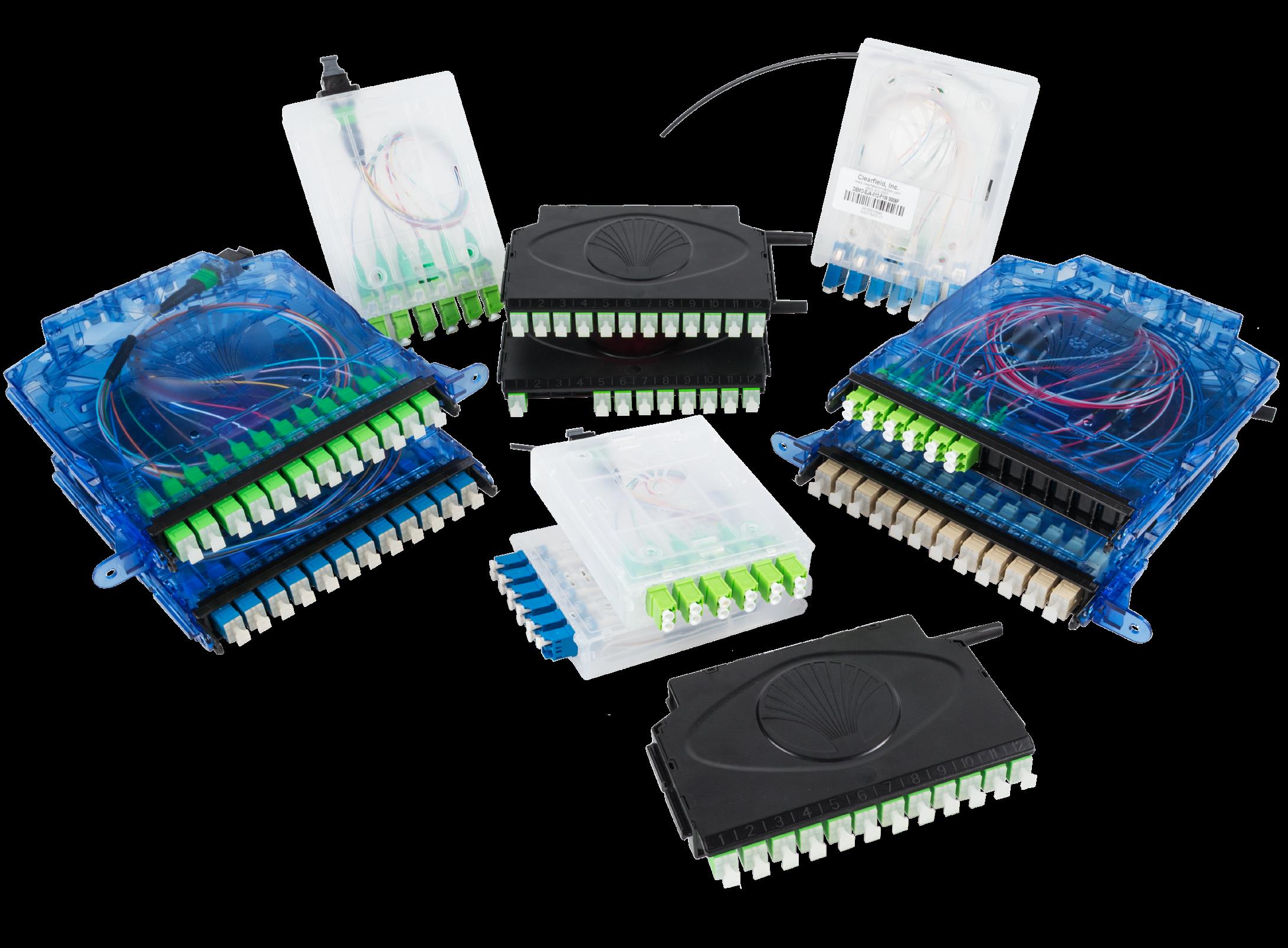
Introduction to Clearview ® Cassettes and xPAK
At the heart of everything we do is our patented Clearview Cassette. Clearview Cassette products offer a unique, single-architecture, modular fiber management platform designed to lower the cost of broadband deployment and maintenance. This is accomplished by consolidating, protecting and distributing incoming and outgoing fiber circuits, allowing our customers to scale their operations as their subscriber revenues increase.
Clearview Blue and Clearview Black, are the core building block of every product within the FieldSmart ® fiber management system. At Clearfield ®, we believe fiber management needs to be different. Rather than using a fixed approach, we take a modular approach. Utilizing the Clearview Cassette provides our customers a scalable and flexible architecture that can take you from the CO all the way to the demarc. To accomplish this objective, fiber management should be designed from “the inside out.”
FieldSmart is the only fiber management platform designed around a single architecture - the Clearview Cassette family of products.
FieldSmart supports a wide range of panel and cabinet configurations, densities, connectors and adapter options for the inside plant, outside plant and access network. Customers benefit from Clearfield’s innovative, scalable and modular designs that allow you to “grow-as-you-go.”
Clearfield’s portfolio of cassette products can be configured for various applications. Patch only, patch and splice (Clearfield’s in-cassette splicing solution), MPO, plug-and-play and passive optical components.
Delivering the most scalable fiber management platform in the industry, Clearfield ensures your investment in capital equipment grows alongside your take rates. With Clearfield, deployments are quicker, required inventories are reduced and technical training is virtually eliminated.

Clearview Cassettes
Introduction to Clearview ® Cassettes
and xPAK
The Clearview Cassette building blocks are well suited for multiple applications in both inside plant, outside plant and access environments. For inside plant environments, high density solutions save floor space, which is always a goal in a central office, headend, data center and customer premise facility. In the outside plant environments, the Clearview Cassette can be deployed in OSP cabinets, pedestals, wall boxes and the FieldSmart ® Makwa™
Configurations are available that support patch and splice (Clearfield’s in-cassette splicing solution), patch only, MPO and optical component scenarios, allowing many different engineering configurations to be met using a single platform. A common platform used in multiple applications helps with technician training, making them ready to perform their work regardless of the installation environment. This saves time during initial installation, turn-up of new services or in critical repair situations.
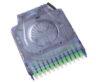
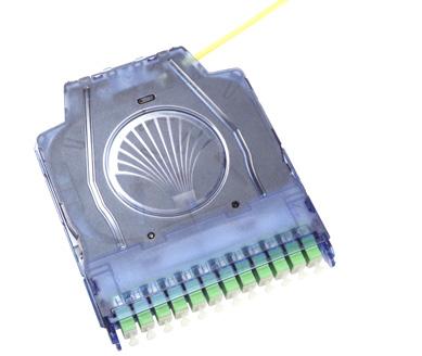
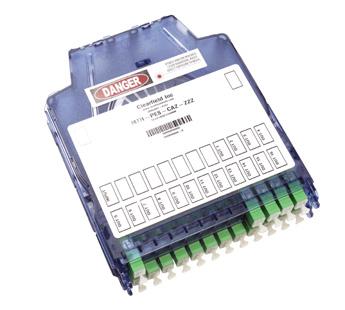
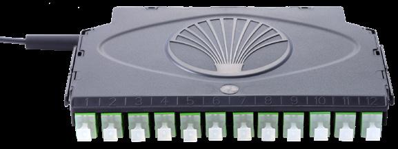
Clearview Blue
The small footprint of the Clearview Blue design minimizes space requirements thereby reducing the cost of deployment. Integrated slack management and cable routing provides for superior performance with minimal risk of fiber damage. It incorporates flexibility and scalability with configuration options supporting tool-less installation, in-cassette buffer tube/ribbon slack storage and front access only designs. Reducing the overall footprint of the fiber management element reduces real estate costs and improves density without compromising critical design elements of access, bendradius protection, physical fiber protection, and route-path diversity.
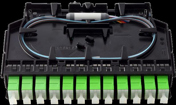
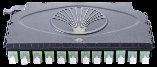
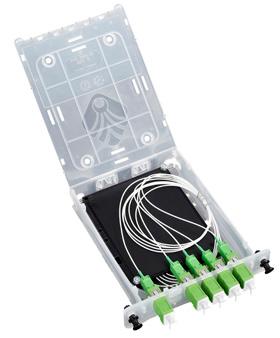
Clearview Black
The Clearview Black Cassette is Clearfield’s most compact building-block technology and retains the same cost saving features of Clearfield’s current generation of cassettes, including modularity and scalability in increments of 12 fibers using industry standard SC and LC singlemode connectors. In addition, critical design elements of fiber access, bend-radius protection and route-path diversity have been maintained while occupying nearly 50% less overall size. The smaller packaging allows Clearview Black to be integrated into other Clearfield solutions like the below grade, FieldSmart Makwa. Clearview Black uses a tool free, snap-in-place mounting feature. With more and more nonspecialized technicians being employed in the workforce, the scalable platform that provides the ability to “grow-as-you-go” without any installation tools is increasingly valuable.
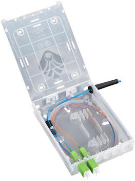
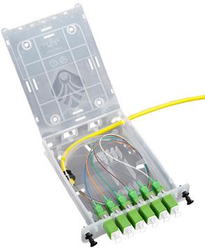
xPAK
Engineered to land small port count fiber assemblies and optical components as conveniently and inexpensively as possible, the Clearview xPAK simplifies fiber management to the level of a consumable good. Clearview xPAK is single-piece element in which all required components for fiber protection are integrated. It is shipped flat and simply folds to shape.
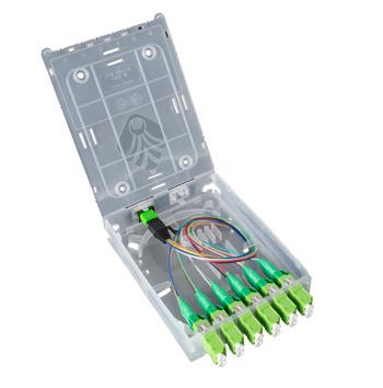
The Clearview xPAK is a small footprint two, four, six or 12* port cassette. The kit comes equipped with a flat cassette, adapters, 2, 4, 6 or 12* fiber 900 μm ½ meter assembly, splice sleeves, strain relief boot, grommet tape and zip ties.
* 12 port option only available as LC


Clearview ® Cassette
Clearview Blue
Application
Based on the choice of adapter style, the Clearview Blue provides 12-24 ports of connectivity, scaling one cassette at a time.
• Deployed with SC or LC connectors for 12-24 ports of connectivity, a single the Clearview Blue Cassette provides for patch and splice (Clearfield’s in-cassette splicing solution), patch only (stubbed) or plug-and-play (MPO/MTP) configurations in any network environment. A dual high 24 fiber Cassette offers additional splicing capacity for SC port count requirements greater than 12, utilizing the Clearview Expansion Ring to provide further flexibility and scalability within the same footprint. Dual MPO/MTP access is available on either side of the cassette. Additional optical components integrate into the cassette housing, supporting any input/output combination of splitting, mux, and demux strategies desired.
Description
Clearview Blue Cassettes are the core building block of nearly every product within the FieldSmart ® fiber management system. Clearview Blue incorporates flexibility and scalability, within multiple configuration options, tool-less installation, in-cassette buffer tube/ribbon slack storage, and front access-only designs. Reducing the overall footprint of the fiber management element reduces real estate costs and improves density without compromising the critical design elements of access, bend-radius protection, physical fiber protection and route-path diversity.
Clearview Blue is a five component, tool-less system made up of a top cover, splice tray, buffer tube/ribbon slack storage, cable assembly tray and adapter plate. Parts snap together to support desired application requirements. All types of fiber cable construction can be integrated within the cassette to support in-cassette splicing, patch only, passive optical component hardware and plug-and-play scenarios.
Features
and Benefits
Integrity
• Termintions designed, tested and certified to GR-326 and GR-1435
• Cassette designed, tested & certified to GR-63 Flame Spread & Chemical


• Clearfield ® FiberDeep ® Guarantee: 0.2 dB insertion loss or less, exceeding industry standards
• Supports industry standard SC, LC and MPO/MTP singlemode and multimode connectors
• Supports all fiber construction types (distribution, tight-buffer, loose tube and ribbon)
Protection
• Designed to handle the toughest operating environments, provides flexibility and reliable performance
• Slack stored, bend-radius protected and secured against accidental physical damage from handling
• Integrated buffer tube storage removes the need for traditional slack storage baskets, reels and troughs and aligns individual buffer tube to the cassette
Access
• Tool-less, snap together design makes turn-up time even faster
• Eight buffer tube/cable entry/exit paths allow the technician a high degree of flexibility in deployment
• Ability to store 10 feet (3.05 m) of exposed buffer tube in the in-cassette buffer tube location
• Translucent housing provides quick visual inspection, while removable adapter plate allows for easy front access for maintenance, cleaning and troubleshooting
• Front-access to pre-terminated assemblies with Clearview removable adapter plate
• Integrated in-cassette buffer tube slack storage aligns slack to individual cassettes maximizing density by reducing real estate requirements
Investment
• “Grow-as-you-go”
• Scalable building block to align capital expenditures to customer take rates
• Modular design allows ports to be configured to user-defined application requirements
• Patch and splice integrated splice tray removes the need for separate chassis space or a splice enclosure reducing the required real estate
Clearview ® Cassette
Clearview Blue
Technical Specifications
Clearview Blue Cassette
Dimensions
Ratings
Backwards Compatible
Material
Without Mounting Ears: 0.81” (20.57 mm) H x 6.03” (153.16 mm) W x 8.28” (210.30 mm) D
With Mounting Ears: 0.81” (20.57 mm) H x 8.66” (219.96 mm) W x 8.28” (210.30 mm) D
Terminations are designed and tested to Telcordia GR-326; Tested to GR-63 NEBS 3 and UL 94 V-0; Clearfield ® FiberDeep ® Guarantee: 0.2 dB insertion loss or less, exceeding industry standards.
Optional mounting ears for backwards compatible to FieldSmart ® Inside plant (FxDS), OSP and access product lines
Polycarbonate
Operating Temperature -40°C to +85°C (-40°F to +185°F)
Storage Temperature -40°C to +85°C (-40°F to +185°F)
Connector Types
Meters/Feet of Slack Storage
Supports industry standard SC, LC and MPO/MTP singlemode and multimode connectors
Up to 10 feet of buffer tube storage in the bottom of the cassette; one meter of 250 μm used for internal splicing for patch and splice (Clearfield’s in-cassette splicing solution)
Mounting Options Clearview Building Block or Clearview Mounting Ears
Cassette Configuration Options
Patch and Splice
The Patch and Splice cassette has a splice tray that nests into the lower tray allowing integrated splicing directly in the cassette. The integrated splice tray eliminates the need for dedicated splice chassis space thus reducing real estate. The cassette provides 12 ports of connectivity with the ability to scale one cassette at a time. Utilizing the dual snapin splice chip option you add an additional 12 splices for a total of 24 splices in one cassette (LC connectors). The 24 port expansion cassette doubles the height and allows 24 splices in a 2 high cassette (SC connectors). Cassettes are pre-loaded with a one meter, 250 μm fiber assembly, loose tube or ribbon, which is pre-terminated and slack stored inside the cassette. For 24 fiber loose tube configurations, 40mm splices sleeves are required (60mm sleeves will not fit). Additionally, in the bottom of the cassette, there is an area to house up to 10 feet (3.05 m) of buffer tube storage with eight cable entry/exit locations for the maximum in flexibility.
Patch Only
Regardless of the industry standard adapters or cable construction, the Clearview Blue handles all patch only applications using the lower tray, top cover, built in radius limiter and removable adapter plate. A patch only cassette can be configured with most industry standard adapters and cable types.
Optical Components
Clearview Blue integrates optical components into the identical cassette, allowing service providers to mix and match fiber modules with optical components in the same chassis. The front faceplate is secured to reduce the chance of accidental damage to the optical component.
MPO Plug-and-Play
MPO to industry standard connector allows for plug-and-play by mating MPO to MPO with pre-terminated multi-fiber OSP or IFC. Also available in dual MPO 24-fiber configuration.

Clearview ® Cassette
Clearview Blue
Pre-Configured Part Numbers
Patch and Splice - 12 Port With Mounting Ears
Part Number
EPZ-012-A1F-SUB
EPZ-012-A2F-SUB
EPZ-012-C1F-SUB
EPZ-012-C2F-SUB
EPZ-012-F1F-SUB
EPZ-012-F2F-SUB
EPZ-012-H1F-SUB
EPZ-012-H2F-SUB
Description
Clearview Blue Cassette, Loose Tube, Patch and Splice, Loaded with 12 SC/UPC Adapters, Singlemode, Mounting Ears Included
Clearview Blue Cassette, Ribbon, Patch and Splice, Loaded With 12 SC/UPC Adapters, Singlemode, Mounting Ears Included
Clearview Blue Cassette, Loose Tube, Patch and Splice, Loaded with 12 SC/APC Adapters, Singlemode, Mounting Ears Included
Clearview Blue Cassette, Ribbon, Patch and Splice, Loaded with 12 SC/APC Adapters, Singlemode, Mounting Ears Included
Clearview Blue Cassette, Loose Tube, Patch and Splice, Loaded with 12 LC/UPC Adapters, Singlemode, Mounting Ears Included
Clearview Blue Cassette, Ribbon, Patch and Splice, Loaded with 12 LC/UPC Adapters, Singlemode, Mounting Ears Included
Clearview Blue Cassette, Loose Tube, Patch and Splice, Loaded with 12 LC/APC Adapters, Singlemode, Mounting Ears Included
Clearview Blue Cassette, Ribbon, Patch and Splice, Loaded with 12 LC/APC Adapters, Singlemode, Mounting Ears Included
Patch and Splice - 12 Port Without Mounting Ears
Part Number
EMZ-012-A1F-SUB
EMZ-012-A2F-SUB
EMZ-012-C1F-SUB
EMZ-012-C2F-SUB
EMZ-012-F1F-SUB
EMZ-012-F2F-SUB
EMZ-012-H1F-SUB
EMZ-012-H2F-SUB
Description
Clearview Blue Cassette, Loose Tube, Patch and Splice, FxHD Frame System, Loaded With 12 SC/UPC Adapters, Singlemode, No Mounting Ears Included, Used For HD Frame
Clearview Blue Cassette, Ribbon, Patch and Splice, FxHD Frame System, Loaded With 12 SC/UPC Adapters, Singlemode, No Mounting Ears Included, Used For HD Frame
Clearview Blue Cassette, Loose Tube, Patch and Splice, FxHD Frame System, Loaded With 12 SC/APC Adapters, Singlemode, No Mounting Ears Included, Used For HD Frame
Clearview Blue Cassette, Ribbon, Patch and Splice, FxHD Frame System, Loaded With 12 SC/APC Adapters, Singlemode, No Mounting Ears Included, Used For HD Frame
Clearview Blue Cassette, Loose Tube, Patch and Splice, FxHD Frame System, Loaded With 12 LC/UPC Adapters, Singlemode, No Mounting Ears Included, Used For HD Frame
Clearview Blue Cassette, Ribbon, Patch and Splice, FxHD Frame System, Loaded With 12 LC/UPC Adapters, Singlemode, No Mounting Ears Included, Used For HD Frame
Clearview Blue Cassette, Loose Tube, Patch and Splice, FxHD Frame System, Loaded With 12 LC/APC Adapters, Singlemode, No Mounting Ears Included, Used For HD Frame
Clearview Blue Cassette, Ribbon, Patch and Splice, FxHD Frame System, Loaded With 12 LC/APC Adapters, Singlemode, No Mounting Ears Included, Used For HD Frame
Clearview ® Cassette
Clearview Blue
Pre-Configured Part Numbers
Patch and Splice - 12 Port With Universal Mounting Kit Part Number Description
EYZ-012-A1F-SUB
EYZ-012-A2F-SUB
EYZ-012-C1F-SUB
EYZ-012-C2F-SUB
EYZ-012-F1F-SUB
EYZ-012-F2F-SUB
EYZ-012-H1F-SUB
EYZ-012-H2F-SUB
Mounting Ear Kit
Part Number
FMA-XXX-181
Clearview Blue Cassette, Loose Tube, Patch and Splice, Loaded with 12 SC/UPC Adapters, Singlemode, 2 Mounting Ears, 1 Push Pull Grommet and Plunger, 2 Fillister Screws
Clearview Blue Cassette, Ribbon, Patch and Splice, Loaded With 12 SC/UPC Adapters, Singlemode, 2 Mounting Ears, 1 Push Pull Grommet and Plunger, 2 Fillister Screws
Clearview Blue Cassette, Loose Tube, Patch and Splice, Loaded with 12 SC/APC Adapters, Singlemode, 2 Mounting Ears, 1 Push Pull Grommet and Plunger, 2 Fillister Screws
Clearview Blue Cassette, Ribbon, Patch and Splice, Loaded with 12 SC/APC Adapters, Singlemode, 2 Mounting Ears, 1 Push Pull Grommet and Plunger, 2 Fillister Screws
Clearview Blue Cassette, Loose Tube, Patch and Splice, Loaded with 12 LC/UPC Adapters, Singlemode, 2 Mounting Ears, 1 Push Pull Grommet and Plunger, 2 Fillister Screws
Clearview Blue Cassette, Ribbon, Patch and Splice, Loaded with 12 LC/UPC Adapters, Singlemode, 2 Mounting Ears, 1 Push Pull Grommet and Plunger, 2 Fillister Screws
Clearview Blue Cassette, Loose Tube, Patch and Splice, Loaded with 12 LC/APC Adapters, Singlemode, Mounting Ears Included
Clearview Blue Cassette, Ribbon, Patch and Splice, Loaded with 12 LC/APC Adapters, Singlemode, 2 Mounting Ears, 1 Push Pull Grommet and Plunger, 2 Fillister Screws
Description
Kit, Mounting Tab, Clearview Blue Cassette, Includes 2 Tabs, 2 Screws and Push-Pull, Universal Mounting Options
Patch and Splice - 24 Port With Mounting Ears
Part Number
EPZ-024-A1F-SUB
EPZ-024-A2F-SUB
EPZ-024-C1F-SUB
EPZ-024-C2F-SUB
EPZ-024-F1F-SUB
EPZ-024-F2F-SUB
EPZ-024-H1F-SUB
EPZ-024-H2F-SUB
Description
Clearview Blue Cassette, Loose Tube, Patch and Splice, 2 High, Loaded With 24 SC/UPC Adapters, Singlemode, Mounting Ears Included
Clearview Blue Cassette, Ribbon, Patch and Splice, 2 High, Loaded With 24 SC/UPC Adapters, Singlemode, Mounting Ears Included
Clearview Blue Cassette, Loose Tube, Patch and Splice, 2 High, Loaded With 24 SC/APC Adapters, Singlemode, Mounting Ears Included
Clearview Blue Cassette, Ribbon, Patch and Splice, 2 High, Loaded With 24 SC/APC Adapters, Singlemode, Mounting Ears Included
Clearview Blue Cassette, Loose Tube, Patch and Splice High Density, 1 High, Loaded With 24 LC/ UPC Adapters, Singlemode, Mounting Ears Included
Clearview Blue Cassette, Ribbon, Patch and Splice, High Density, 1 High, Loaded With 24 LC/UPC Adapters, Singlemode, Mounting Ears Included
Clearview Blue Cassette, Patch and Splice, High Density, 1 High, Loaded With 24 LC/APC Adapters, Singlemode, Mounting Ears Included
Clearview Blue Cassette, Ribbon, Patch and Splice, High Density, 1 High, Loaded With 24 LC/APC Adapters, Singlemode, Mounting Ears Included
Clearview ® Cassette
Clearview Blue
Patch and Splice - 24 Port With Universal Mounting Ears
Part Number
EYZ-024-A1F-SUB
EYZ-024-A2F-SUB
EYZ-024-C1F-SUB
EYZ-024-C2F-SUB
EYZ-024-F1F-SUB
EYZ-024-F2F-SUB
EYZ-024-H1F-SUB
EYZ-024-H2F-SUB
Clearview Blue Cassette, Loose Tube, Patch and Splice, 2 High, Loaded With 24 SC/UPC Adapters, Singlemode, 2 Universal Mounting Ears, 1 Push Pull Grommet and Plunger, 2 Filister Screws
Clearview Blue Cassette, Ribbon, Patch and Splice, 2 High, Loaded With 24 SC/UPC Adapters, Singlemode, 2 Universal Mounting Ears Included, 1 Push Pull Grommet and Plunger, 2 Filister Screws
Clearview Blue Cassette, Loose Tube, Patch and Splice, 2 High, Loaded With 24 SC/APC Adapters, Singlemode, 2 Universal Mounting Ears, 1 Push Pull Grommet and Plunger, 2 Filister Screws
Clearview Blue Cassette, Ribbon, Patch and Splice, 2 High, Loaded With 24 SC/APC Adapters, Singlemode, 2 Universal Mounting Ears, 1 Push Pull Grommet and Plunger, 2 Filister Screws
Clearview Blue Cassette, Loose Tube, Patch and Splice High Density, 1 High, Loaded With 24 LC/UPC Adapters, Singlemode, 2 Universal Mounting Ears, 1 Push Pull Grommet and Plunger, 2 Filister Screws
Clearview Blue Cassette, Ribbon, Patch and Splice, High Density, 1 High, Loaded With 24 LC/UPC Adapters, Singlemode, 2 Universal Mounting Ears, 1 Push Pull Grommet and Plunger, 2 Filister Screws
Clearview Blue Cassette, Patch and Splice, High Density, 1 High, Loaded With 24 LC/APC Adapters, Singlemode, 2 Universal Mounting Ears, 1 Push Pull Grommet and Plunger, 2 Filister Screws
Clearview Blue Cassette, Ribbon, Patch and Splice, High Density, 1 High, Loaded With 24 LC/APC Adapters, Singlemode, 2 Universal Mounting Ears, 1 Push Pull Grommet and Plunger, 2 Filister Screws
One Cassette High
Configured Part Numbers
Two Cassettes High
Disclaimer/Note: Paper configurator shown is for reference only and should not be used to configure a saleable product configuration. All options shown on paper configurators may not be available or compatible with other options listed. Please contact your Clearfield representative for assistance in product configurations.
Select Connector
6 Select Cable Construction
A = Indoor riser rated
B = OSP riser rated
C = Indoor, plenum rated
E = OSP (non-rated)
M = OSP (armored)
5 Select Mode / Type 1 = Singlemode – loose tube 2 = Singlemode – ribbon 3 = Multimode (62.5) XXXM = Length in meters
T = FLATdrop, non-toneable
U = FLATdrop toneable
W = FieldShield
Clearview ® Cassette
Clearview Blue
Configured Part Numbers
Disclaimer/Note: Paper configurator shown is for reference only and should not be used to configure a saleable product configuration. All options shown on paper configurators may not be available or compatible with other options listed. Please contact your Clearfield representative for assistance in product configurations.
EQR-012-C1F-SUB
EQL-012-F1F-SUB
EQR-012-F1F-SUB
EQL-012-H1F-SUB
EQR-012-H1F-SUB
Clearview Blue Cassette, MPO, MPO (Male) to SC/APC, MPO Rear Access and SC/APC Front Access Adapters, Singlemode, Left Exit, Includes Kit of 2 Ears with Universal Mounting Options
Clearview Blue Cassette, MPO, MPO (Male) to SC/APC, MPO Rear Access and SC/APC Front Access Adapters, Singlemode, Right Exit, Includes Kit of 2 Ears with Universal Mounting Options
Clearview Blue Cassette, MPO, MPO (Male) to LC/UPC, MPO Rear Access and LC/UPC Front Access Adapters, Singlemode, Left Exit, Includes Kit of 2 Ears with Universal Mounting Options
Clearview Blue Cassette, MPO, MPO (Male) to LC/UPC, MPO Rear Access and LC/UPC Front Access Adapters, Singlemode Right Exit, Includes Kit of 2 Ears with Universal Mounting Options
Clearview Blue Cassette, MPO, MPO (Male) to LC/APC, MPO Rear Access and LC/APC Front Access Adapters, Singlemode, Left Exit, Includes Kit of 2 Ears with Universal Mounting Options
Clearview Blue Cassette, MPO, MPO (Male) to LC/APC, MPO Rear Access and LC/APC Front Access Adapters, Singlemode, Right Exit, Includes Kit of 2 Ears with Universal Mounting Options
Clearview ® Cassette Clearview Black
Application
Clearview Black provides 12 to 24 ports of connectivity for patch and splice (Clearfield’s in-cassette splicing solution), patch only and plug-and-play (MPO/MTP) configurations in any network environment. It scales and multiplies to meet your specific port density and application needs. Additionally, optical components integrate into the cassette, supporting any input/output combination of splitting or mux and demux strategy desired. The Clearview Black Cassette is available for ribbon only fiber.
Description
Clearview Black incorporates the same flexibility and scalability of the Clearview Blue, in a 50% smaller footprint. Decreasing the overall footprint of the fiber management element reduces real estate costs and improves density without compromising critical design elements of access, bend-radius protection, physical fiber protection and route-path diversity.
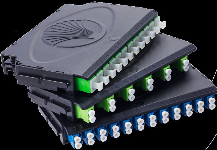
Clearview Black is a three component tool-less system made up of a top cover, base/splice tray and splice tray cover. Parts snap together to support the desired application requirements. All types of fiber cable construction can be integrated within the cassette to support all patch and splice, patch only, plug-and-play, and passive optical component hardware scenarios.
Each patch and splice cassette comes prepared for mass fusion splicing, with one meter of ribbonized 250 μm fiber preloaded and prepped to splice. Each ribbonizing tool aligns and secures the loose tube fibers into correct color code order, allowing ribbonizing to be completed quickly and easily.
For patch only configurations, the pre-terminated length of OSP or IFC cable is pre-loaded within the Clearview Black Cassette. The cassettes are then preloaded into the FieldSmart ® product when shipped.
Features and Benefits Integrity
• Terminations designed, tested and certified to Telcordia GR-326
• MPO Terminations designed, tested and certified to Telcordia GR-1435
• Cassette is designed, tested & certified to GR-63 Flame Spread & Chemical
• Clearfield ® FiberDeep ® Guarantee: 0.2 dB insertion loss or less, exceeding industry standards
• Supports industry standard SC and LC singlemode and multimode connectors
• Supports all fiber construction types - patch and splice must be ribbonized
• Modular and scalable Protection
• Designed to handle the toughest operating environments, provides flexibility and reliable performance
• Slack stored, bend-radius protected and secured against accidental physical damage from handling Access
• Tool-less, snap together design makes turn-up time even faster
• Two buffer tube/cable entry/exit paths allow the technician a high degree of flexibility in deployment
• Front-access to pre-terminated assemblies with Clearview removable lid
• Ribbonizing allows quicker troubleshooting and restoration of affected fibers, as 12 fibers are ribbonized only where the splicing needs to occur, providing single-circuit access if necessary
Investment
• “Grow-as-you-go”
• Scalable (increments of 12 ports) building block to align capital expenditures to customer take rates
• Modular design allows ports to be configured to user-defined application requirements
• Patch and splice - integrated splice tray removes the need for a separate splice enclosure/cases
• 50% smaller footprint than Clearview Blue allows for more density within all application environments
• Patch and splice integrated splice tray removes need for a separate chassis space or splice enclosure reducing the required real estate
• Ribbonizing loose tube cable allows for mass-fusion of up to 12 fibers at a time, reducing installation time and costs
• Brackets for 19” and 23” (482.60 mm and 584.20 mm) frames
Clearview ® Cassette
Clearview Black
Cassette Configuration Options
Patch Only
Regardless of the industry standard adapters or cable construction, the Clearview Black handles all patch only applications using the lower tray, top cover and built in radius limiter.

Patch
and Splice (Clearfield’s In-Cassette Splicing Solution)
The splice tray that is molded into the lower tray is all that is needed to deliver integrated patch and splice applications. Pre-loaded with up to one meter of ribbon, 250 μm assemblies that are perterminated with slack stored inside the cassette for splicing.

Optical Components
Clearview integrates optical components into the identical cassette, allowing service providers to mix and match fiber modules with optical components in the same chassis.
MPO Plug and Play
MPO to industry standard connectors allows for plug-and-play by mating MPO to MPO with preterminated multi-fiber OSP or IFC.
Clearview ® Cassette
Clearview Black
Technical Specifications
Clearview Black Cassette
Dimensions 0.81” H x 6.13” W x 4.14” D (20.57 mm x 155.70 mm x 105.15 mm)
Ratings
Terminations are designed and tested to Telcordia GR-326; Clearfield ® FiberDeep ® Guarantee: 0.2 dB insertion loss or less, exceeding industry standards
Backwards Compatible N/A
Material Polycarbonate
Connector Types Supports industry standard SC and LC singlemode connectors
Meters/Feet of Slack Storage 1 meter of 250 μm used for internal ribbon splicing only
Mounting Options Used with FieldSmart ® BLG Pivot Bracket
Pre-Configured Part Numbers
Part Number Description
E1Z-012-A2F-SUB Clearview Black Cassette, Ribbon, Patch and Splice, Loaded With SC/UPC Adapters, Singlemode
E1Z-012-C2F-SUB Clearview Black Cassette, Ribbon, Patch and Splice, Loaded With SC/APC Adapters, Singlemode
E1Z-012-F2F-SUB Clearview Black Cassette, Ribbon, Patch and Splice, Loaded With LC/UPC Adapters, Singlemode
E1Z-012-H2F-SUB Clearview Black Cassette, Ribbon, Patch and Splice, Loaded With LC/APC Adapters, Singlemode
E1Z-024-F2F-BLACK-SUB Clearview Black Cassette, Ribbon, Patch and Splice, High Density, Loaded With 24 LC/UPC Adapters, Singlemode
E1Z-024-H2F-BLACKSUB Clearview Black Cassette, Ribbon, Patch and Splice, High Density, Loaded With 24 LC/APC Adapters, Singlemode
Configured Part Numbers
Disclaimer/Note: Paper configurator shown is for reference only and should not be used to configure a saleable product configuration. All options shown on paper configurators may not be available or compatible with other options listed. Please contact your Clearfield representative for assistance in product configurations.
Select Cable Construction
A = Indoor riser rated
B = OSP riser rated
C = Indoor, plenum rated
E = OSP (non-rated)
F = Patch and splice cassettes
M = OSP (armored) W = FieldShield
Clearview ® Cassette Clearview xPAK
Application
Engineered to land small port count fiber assemblies and optical components as conveniently and inexpensively as possible, the xPAK simplifies fiber management to the level of a consumable good. Clearview xPAK can be deployed as a stand-alone device, or with FieldSmart ® Fiber Delivery Point (FDP) products for a wide range of network environments.
Description
At first glance, Clearview xPAK looks like any other LGX compatible package, but upon closer inspection, technicians will see a new generation of innovation in the delivery of terminated fiber assemblies. Clearview xPAK is single-piece element in which all required components for fiber protection are integrated. It is shipped flat and simply folds to shape.
The Clearview xPAK supports two, four or six ports of patch and splice (Clearfield’s in-cassette splicing solution) configurations. The compact 4” x 5” (101.60 mm x 127.00 mm) solution is perfect for landing small count terminations at the fiber delivery point. The kit comes with everything you’ll need: flat cassette, adapters, 2, 4 or 6-fiber 900 μm ½ meter assembly, splice sleeves, strain relief boot, grommet tape, zip ties and universal mounting bracket.

Priced to allow field personnel to carry quantities of Clearview xPAK Cassettes in the field, xPAK is shipped flat and unassembled. At the deployment site, the technician will take the xPAK device, and following pictorial user instructions, will assemble the device to match his field requirements. Integrated into the footprint of the device, is an industry-compatible splicing tray, which is then surrounded with fiber protection elements that support either a two, four or six port fiber assembly as well as a range of optical component devices.
Clearview xPAK is the ideal fiber management device when up to six fibers (or us to 12 LC) are landed or an optical component device is deployed in a remote location. Application environments include cell backhaul, business class service delivery, node segmentation, fiber exhaust in a field pedestal, sub-station turn-up or fiber-to-the-desk deployment.
Features and Benefits
Integrity
• Terminations designed, tested and certified to Telcordia GR-326
• Clearfield ® FiberDeep ® Guarantee: 0.2 dB insertion loss or less, exceeding industry standards
• Supports industry standard SC, LC and MPO/MTP singlemode and multimode connectors
• 100% performance tested for insertion loss, return loss and final mechanical inspect Protection
• Radius protected storage for up to ½ meter of 900 μm jacketed fibers
• Durable polypropylene construction (impact plastic)
• Integrated fiber management protects fiber from micro-bend and macro-bend damage Access
• Small design facilitates ease of use in crowded environments
• Easy assembly - no tools required
• Front: 6 SC ports; Rear: 1 SC port or 1 MPO/MTP
• 9 SC port faceplate available Investment
• Pre-configured/factory loaded, patch only factory terminated assemblies
• Patch and splice
• LGX compatible flange mount
• Wall mount capable
• One piece construction with “living hinge”
• Supports optional component integration
• Plug-and-play with MPO configurations
Clearview ® Cassette
Clearview xPAK
Technical Specifications
Clearview xPAK
Dimensions 1.14” H x 4” W x 5.38” D (28.96 mm x 101.60 mm x 136.52 mm)
Ratings
Terminations are designed and tested to Telcordia GR-326; Clearfield ® FiberDeep ® Guarantee: 0.2 dB insertion loss or less, exceeding industry standards
Backwards Compatible N/A
Material
Durable polypropylene (impact plastic)
Connector Types Supports industry standard SC, LC and MPO singlemode and multimode connectors
Meters/Feet of Slack Storage ½ meter of 900 μm tight buffer fiber used for internal splicing, 12-fiber xPAK requires ribbon splicing
Mounting Options Standard faceplate and LGX faceplate
Cassette Configuration Options
Patch and Splice (Clearfield’s In-Cassette Splicing Solution)
The 6-fiber splice tray molded into the xPAK tray is all that is needed to deliver an integrated patch and splice application. 2, 4 or 6-fiber 900 μm ½ meter assemblies are pre-terminated, pre-loaded and slack stored inside the xPAK ready for splicing.
Patch Only
Regardless of the industry standard adapter or cable construction, the pre-terminated length of OSP or IFC cable is pre-loaded within Clearview xPAK for patch only configurations.
MPO Plug-and-Play
MPO to industry standard connectors allows for plug-and-play by mating MPO to MPO with preterminated multi-fiber OSP or IFC.
Optical Components
Optical components can be integrated into the Clearview xPAK.
Clearview ® Cassette
Pre-Configured Part Numbers
Configured Part Numbers
Disclaimer/Note: Paper configurator shown is for reference only and should not be used to configure a saleable product configuration. All options shown on paper configurators may not be available or compatible with other options listed. Please contact your Clearfield representative for assistance in product configurations.
H = LGX mounting
J = Standard mounting
1 2 Select Mounting Option
A = Side right
B = Back right
C = Side left
D = Back left Cable Exit
3 Select Port Count
4 Select Connector Style
A
5 Select Cable Construction
A = Indoor riser rated
B = OSP riser rated
C = Indoor, plenum rated
E = OSP (non-rated)
F = Patch and splice cassettes
M = OSP (armored)
W = FieldShield
XXXM or XXXF
XXXM = Length in meters
XXXF = Length in feet
Clearview ® Cassette
Clearview Blue Mounting Ears Instructions
The Clearview Blue Cassette is able to mount into a number of Clearfield products using a flexible system of mounting ears and retaining screws or push/pull plungers. Below you will find instructions on how to install each mounting variation and a list of products in which each variation will be used.
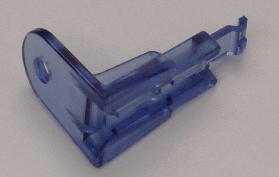
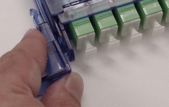
Installing Mounting Ears
From the front of the cassette, slide the mounting ear’s channel onto the t-rail on the side of the cassette. Push the mounting ear until it snaps into place.

Mounting Option Products
No Mounting Ears
One Mounting Ear

FxHD Frame System, Flex Box, KIS Box, NDP Wall Box, 5.5” Deep Indoor/Outdoor SCD Wall Box
FxMP Panels, 144 PON Pedestal Insert
Two Mounting Ears All other products (special cassette mounting instructions may be included with product)
Installing Retaining Screws
To mount cassettes into products utilizing retaining screws, insert the retaining screws into the holes in the mounting ears. Depending on the product, retaining screws will be inserted in either the front or the back of the mounting ear. Screw the cassette into place in the product using the retaining screws.
Mounting Option Products
Front Installed Retaining Screws
Back Installed Retaining Screws
FxDS Panels, FxDS PON Insert, 96 & 144 PON Pedestal Inserts
FSC & FDH Cabinets, 24 & 48 Outdoor Wall Boxes, 36, 96 & 144 Indoor Wall Boxes
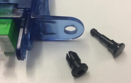
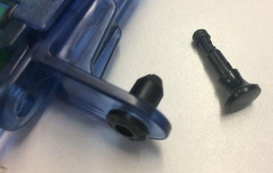
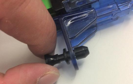
Installing Push/Pull Plungers
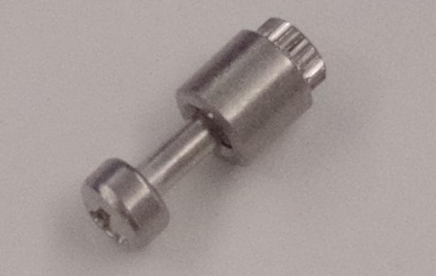
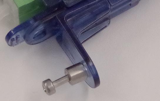
Push/pull plungers are used in FxMP Panels. Push the grommet piece through the hole in the mounting ear, then the plunger. Push the plunger until it clicks, then pull back to release the expansion. To install cassettes into the product, insert the push/pull plunger through the hole and push the plunger to expand the grommet and secure the cassette into place.

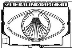
Clearview ® Cassette Exits
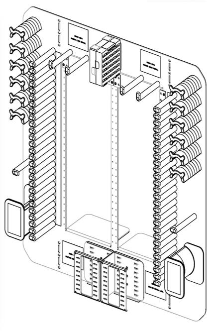
Adding Patch Only Cassettes to Partially Loaded FieldSmart Cabinets
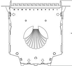
Cassette Exit Diagram
Mounting Ears Required

Top View of Clearview Blue Cassette
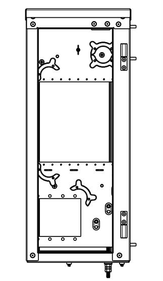
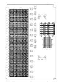
Clearview ® Cassette Exits
Adding Patch Only Cassettes to Partially Loaded FieldSmart Cabinets

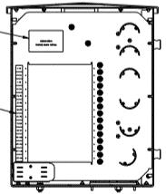
Clearview ® Cassette Exits
Adding Patch Only Cassettes to Partially Loaded FieldSmart Cabinets


Front View
Front View of Cabinet
Front View of
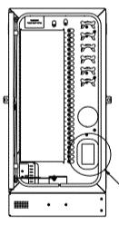
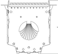
Clearview ® Cassette Exits
Adding Patch Only Cassettes to Partially Loaded FieldSmart Peds
FieldSmart FiberFirst Pedestal with PON Insert

FieldSmart 96 and 144 PON in a Ped Insert

Left Exit
Clearview Black Cassette Exit Diagram
Top View of Clearview Black Cassette
Clearview ® Cassette Exits
Addding Patch Only Cassettes to FieldSmart Wall Boxes
Top Views of Clearview Blue Cassette
Introduction to Inside Plant Solutions
FieldSmart ® Products
FieldSmart is the only fiber management platform designed around a single architecture – the Clearview ® Cassette and the small count Clearview xPAK – for inside plant networks. FieldSmart supports a wide range of panel configurations, densities, connector styles and adapter options.
Designed from the ground up with field-proven experience, the FieldSmart platform is a truly unique solution for today’s rapid deployment demands. With FieldSmart, you control your capital cost, reduce operational costs and provide a consistent product platform throughout the network.
The flexibility in design and configuration of the Clearview Cassette is implemented into all of the FieldSmart products, which are well suited for multiple inside plant applications. The inside plant products provide a system of modular and scalable building blocks to configure a frame system that delivers industry-leading scalability and fiber protection without jeopardizing density or increasing cost.
The Telcordia-certified FieldSmart FxMP Panels are intelligently designed to provide the user with superior fiber access and craft-friendly, radius-protected fiber management for routing and deploying fiber jumpers. The panels fit in 19” or 23” standard frames.
The FieldSmart Fiber Crossover High Density (FxHD) System and the Fiber Crossover Distribution System (FxDS) Frame Kit are both flexible and scalable. Complete compatibility in footprint and route paths between the frames allow you to pick and choose the FxHD and FxDS for any application environment, with future migration built in. You can place a FxHD frame next to a FxDS frame and they will look the same in your lineup.


FieldSmart Frames
FieldSmart Panels
Introduction to Inside Plant Solutions
FieldSmart ® Products
FieldSmart Fiber Crossover High Density (FxHD) Distribution System
Designed for the ultimate in frame density and footprint, the FxHD maximizes your real estate investment providing for a lower total cost of ownership in high density environments. Lower cost of ownership is not only realized in real estate savings but also in installation and service turn-up time, trouble shooting and restoration and MAC (moves, adds and changes) work in interconnect and cross-connect environments.
FieldSmart Fiber Crossover Distribution System (FxDS)
Designed for flexibility of configuration, the FxDS is a series of building blocks in which individual components of the system are configured to the environment in which they are placed. An industry standard 7’ x 19” (2133.60 mm x 482.60 mm) seismic frame is factory kitted and assembled with a set of interbay vertical slack management panels, crossover troughs and removable doors to provide for uninhibited access to routed jumpers and incoming multi-fiber cables. The FxDS requires only 4 SKU’s to configure initial deployment.
FxHD vs. FxDS Frame System Comparison
Clearfield ® extends flexibility with your choice of FieldSmart frame systems. Complete compatibility in footprint and route paths between the frames allow you to pick and choose the FxHD and FxDS for the desired application environment with future migration built in.
Recommended Applications
Description
Large fiber count applications or any space constrained applications - highest fiber count solution available in the marketplace today
Designed for density, the FxHD maximizes your real estate investment and is well suited for high density environments
Medium to large fiber count applications
Designed for flexibility of configuration, the FxDS system can be configured to multiple environments Density
All Front Access
On-frame Splicing
Yes - can be deployed back to back
Excellent - with no loss of density; splicing in Clearview ® Blue Cassette
Off-frame Splicing N/A
Slack Storage
Built into frame
No - front and rear access
Excellent - with no loss of density; splicing in Clearview Blue Cassette
Excellent - using patch only Clearview Cassette
Built into frame kit
FieldSmart FxHD
FieldSmart FxDS
FieldSmart® Fiber Crossover High Density (FxHD) Frame
Application
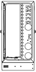
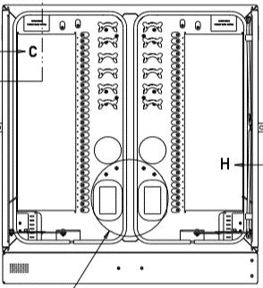
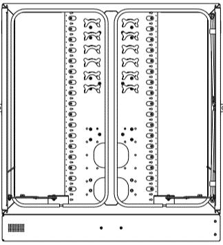
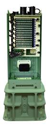
With the FieldSmart FxHD front access design, Clearview ® Cassettes are shifted to the outside of the frame and away from a fixed panel configuration. Instead of traditional panel configurations, the frame is configured with a series of Clearview Blue cassettes teamed with building brackets built into user-defined building blocks. The FxHD Frame provides the ultimate in modularity and flexibility to scale from 12 to 2,016 ports in any fiber count optimizing your ability to maximize fiber investment and assets. Clearview Blue’s in-cassette buffer tube storage allows the FxHD to reclaim the space used for traditional panels and mass buffer storage and to redeploy it by using building blocks of Clearview Blue Cassettes.
Description
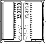
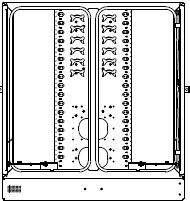
The FieldSmart High Density Fiber Crossover Distribution System (FxHD) is the highest density fiber management frame solution available in the industry today, providing 2,016 SC terminations in a 7’ (2133.60 mm) frame or when mounted back-to-back, FxHD supports a maximum density of 4,032 terminations in a space savings footprint of 9 square feet (36” x 36”) (914.40 mm x 914.40 mm).

FieldSmart FxHD is an integrated fiber management solution utilizing the Clearview Blue Cassette. Designed around the same footprint as the FxDS fiber frame at 18” x 36” (457.20 mm x 914.40 mm) and utilizing the same full length doors for maximum physical fiber protection, the FxHD easily integrates alongside existing FieldSmart FxDS or other industry standard frame systems. Those deploying the FieldSmart FxHD can start with one Clearview Blue Cassette and add additional cassettes as additional capacity is needed, up to a total of 168 cassettes and 2016 ports of connectivity. This port count represents an additional 288 ports in a standard 7’ (2133.60 mm) frame – or a 17% increase in density over the FxDS frame solution. With instant access to all cassettes, adapters and jumpers, the frame is designed as a front access frame. This means that all of your installation, MAC (moves, adds and changes) work and routing of jumpers is done from one side of the frame providing you the option to reclaim the aisle space required for frame solutions that require rear access - and to use that space for other equipment or more frames. The FxHD can be placed against a wall, a cage in data center collocation environments or installed back to back. The FxHD frame solution provides a 40% reduction in floor space requirement while still meeting 30” (762.00 mm) aisle spacing requirements.
Designed in conjunction with Clearview Blue, the FxHD extends the Clearfield ® commitment to modular and scalable solutions by introducing tech-friendly, tool-less deployment to standard building blocks. Individual components are configured to application requirements while providing bend-radius protection, physical fiber protection and route-path diversity for the consolidation and distribution of fiber.
User-defined Clearview building blocks configured to exact port count specifications can be deployed in seconds with Smart-Connect tool-less fasteners. Clearview Blue Cassettes simply slide into building block assemblies with a “hard-stop” feature ensuring perfect alignment every time. Additional buffer tube/ribbon slack is stored within each cassette eliminating buffer tube congestion, pile-up or identification miscues. The dedicated “w-shaped” intrabay route scheme ensures long term reliability of circuits by maximizing proper slack storage of any jumper length, greatly reducing the chance of jumper tie-in or weaving. Full length doors provide complete physical fiber protection when closed and instant visual and physical access to the entire frame when opened.
For scenarios where maximizing real estate is a premium, service providers may choose to deploy an FxHD front only access, allowing frames to be mounted back-to-back or against structures such as walls, existing frame equipment or building supports.
Features and Benefits
Integrity
• One frame size accommodates up to 2,016 ports or 4,032 ports when back-to-back
• Supports all industry standard singlemode and multimode connectors
• 100% performance tested for insertion loss, return loss and final mechanical inspection
• Supports distribution, tight-buffer and ribbon fiber types for inside and outside plant constructions
Protection
• Full length doors provide visual and physical access to the entire frame when opened and complete physical fiber protection when closed
• Complete bend-radius protection throughout all routing schemes
• Diverse route-paths minimize cable pile-up and ensure long term reliability of circuits
Cube Bracket
FieldSmart® Fiber Crossover High Density (FxHD) Frame
• Integrated “w-shaped” intrabay route scheme does not compete with adjacent frames and maximizes proper slack storage of any jumper length, greatly reducing the chance of jumper tie-in or weaving (4 meters suggested)
• Radius protected storage for up to 10 feet (3.04 M) of buffer tube slack provided in Clearview Blue Cassette
Access
• FxHD is front access only to ensure maximum accessibility to achieve 2016 SC terminations or 4032 in a back-to-back frame system
• Top entry/exit through horizontal fiber trough and bottom entry through raised floors supported front and rear of frame
• Fold-down trough door allows complete access to interbay lay-in routing for 6,000 jumpers (3,000 left and 3,000 right) through the frame and adjacent frames
• A four meter jumper can get you from any port to any port
• Supports SmartRoute rear interbay troughing route-paths
• Uses Clearview ® Blue Cassette front access with removable 12-pack adapter plate allowing quick and easy access to back of adapters for troubleshooting, maintenance and cleaning without disturbing live circuits in other cassettes
Investment
• Fully loaded or “grow-as-you-go” integration allows the user choices to provide for cost containment as subscriber take-rates dictate
• Compatible alongside FxDS frame line up as well as traditional 19” (482.60 mm) or 23” (584.20 mm) frame solutions
• Pre-configured/pre-loaded factory terminated assemblies
• Custom configured with standard building blocks supporting all application environments
• Patch and splice (Clearfield’s in-cassette splicing solution), patch only and plug-and-play configurations supported
Technical Specifications
FieldSmart FxHD Frames
Dimensions 7’ H x 36” W x 18” D
Ratings Designed to comply to Telcordia GR-449
Port Density 2,016 SC or 4,032 LC (front access only, back-to-back mounting)
Cassette Types Supported Clearview Blue
Connector Types SC/UPC, SC/APC, LC/UPC, LC/APC, MPO (additional options available upon request)
Cable Types
Indoor Riser, Indoor Plenum, Indoor/Outdoor, Outdoor (Riser/Non-Rated), Outdoor Armored (Riser/NonRated), FieldShield ®
Splice Capacity 12-24 splices in each Clearview Cassette
Storage Capacity One meter of 900 μm fiber and up to three meters of jacketed fiber
Cable Entry Compatibility Top and bottom (floor) entry
Cable Entry Clamp Location 16 (eight left, eight right)
Note: Center clamping compatible for left and right same sheath distribution of buffer tubes/sub units
Recommended Jumper Length Four meters, plus two meters (13’ + 6.6’) for each additional frame
Material Stainless steel with almond powder coating
Pre-Configured Part Numbers
Part Number Description
014602-PATCH AND SPLICE FxHD kit, patch and splice, front access only, maximum 2,016 ports (includes built in fiber management and cassette mounting brackets, doors, iso pad, floor mount kit)
014602-PATCH ONLY FxHD kit, patch only, front access only, maximum 2,016 ports (includes built in fiber management, two doors, iso pad, floor mount kit)
014743 FxHD 576 port PON Insert (Select one of the following part numbers for feeder ports.)
FieldSmart® Fiber Crossover High Density (FxHD) Tie Panel
Application
Provides an in the field configured interconnect or cross-connect environment for 12 to 2,016 ports of high density fiber in the central office and headend environments.
Description
The FieldSmart FxHD Tie Panel is a high density, low-maintenance fiber distribution system exclusively for the FxHD frame system. Tie panels are intelligently designed to provide the user with superior fiber access while using craft-friendly radius protected fiber management for routing and deploying fiber jumpers or multi-fiber cables, on both sides of the adapter plate for cross-connect environments.
Features and Benefits
Integrity
• Terminations designed, tested and certified to Telcordia GR-326
• Supports all industry standard singlemode and multimode connectors and cabling Protection
• Ruggedized hinged bulkhead
• Cable clamp protects against twisting and pistoning at the assembly breakout point Access
• Front access frame system
• Front and rear access via hinged bulkhead Investment
• Panel sizes available in 24 ports
• “Grow-as-you-go” integration allows the user choices to provide for cost containment as subscriber take-rates dictate
• Industry-leading density, 2,016 ports in a 7’ (2133.60 mm) FxHD frame system
Technical Specifications
FieldSmart® Fiber Crossover High Density (FxHD) Tie
Panel
Pre-Configured Part Numbers
Part Number
FMA-XXX-68
FMA-XXX-69
FMA-XXX-70
FMA-XXX-73
FMA-XXX-74
FMA-XXX-75
FMA-XXX-76
FMA-XXX-77
FMA-XXX-78
Description
FxHD Tie Panel Bulkhead - four 24 port - SC/UPC SM, two left and two right
FxHD Tie Panel Bulkhead - four 24 port - SC/APC SM, two left and two right
FxHD Tie Panel Bulkhead - four 24 port - LC/UPC SM, two left and two right
Left tie plate - looking from the front. 24 x LC/UPC singlemode
Left tie plate - looking from the front. 24 x SC/UPC singlemode
Left tie plate - looking from the front. 24 x SC/APC singlemode
Right tie plate - looking from the front. 24 x LC/UPC singlemode
Right tie plate - looking from the front. 24 x SC/UPC singlemode
Right tie plate - looking from the front. 24 x SC/APC singlemode
Pre-Configured Part Numbers - Accessory
008140 Frame Clamp Kit, includes , ¼, ½, ¾, ⅞ and 1” saddle clamps and grommet tape 7
FieldSmart® Fiber Crossover Distribution System (FxDS) Frame Kit
Application
The FxDS Frame Kit is a fully contained fiber management system for the inside plant. The seven foot seismic frame is provided along with full length front and rear doors that provide protection for termination fields, incoming distribution cables and interbay routed jumpers. When used in conjunction with the FxDS panels, ultimate density and protection is offered at “grow-as-you-go” cost.
Description
The FieldSmart Fiber Crossover Distribution System (FxDS) provides a system of modular and scalable building blocks to configure a frame system that delivers industry-leading scalability and fiber protection without jeopardizing density or increasing cost.
The FxDS system easily configures for panel placement and scales simply from 12 ports to a full rack of 1,728 ports as needed. The FieldSmart FxDS requires only four unique building blocks (SKUs) to configure initial deployment. The user then adds into the frame whatever is needed as subscriber take rates dictate. The FxDS Frame Kit is an industry standard 7’ x 19” (2133.60 mm x 482.60 mm) seismic frame that is easily assembled with a set of vertical interbay slack management panels, two upper and lower crossover troughs and a set of removable doors.
With SmartRoute Trough

SmartRoute Troughing builds upon the cable management functionality with a sleek method of providing a continuous channel for bay-tobay routing in a safe and efficient manner without increasing jumper lengths. SmartRoute Troughing allows the service provider to carry the distance and weight of thousands of jumpers on a horizontal plane. This spreads the pile up and eliminates the risk of micro and macro bends. When used across multiple frames, up to three continuous channels are created allowing bay-to-any-bay routing in a safe and efficient manner.
With PON Kit
Front route troughs are available when the frame is deployed with a PON Kit or for environments where interbay routes are not anticipated.
Features and Benefits
Integrity
• Designed to comply to Telcordia GR-449
• Zone 4 Seismic Rated
• Scales easily from 12 ports to 1,728 ports on a full frame
• Easily configured for initial placement Protection
• Complete bend-radius protection of all fiber cable throughout the routing schemes
• Diverse route-paths minimize cable pile-up and ensure long term reliability of the circuits
Access
• Front and rear access
• Interbay for each frame is not shared with adjacent frames. Minimizes cable crossover and tie-ins, allowing for easy identification
• Removable full length doors allow for superior access to routed jumpers and incoming distribution cables
Investment
• One frame size (7’ x 19”; 2133.60 mm x 482.60 mm) accommodates up to 1,728 ports or 1,152 ports in a PON environment, with full horizontal and vertical slack management support
• Compatible with Clearview ® optical component packaging that integrates into crossover bulkheads, eliminating the need to dedicate a separate chassis
• Fully loaded or “grow-as-you-go” integrations allow the user choices to provide for cost containment as subscriber take-rates dictate
• Frame components are used throughout the network from inside plant to outside plant to access networks
• Custom configured with common building blocks, it supports any and all applications
FieldSmart® Fiber Crossover Distribution System (FxDS) Frame Kit
Technical Specifications
FieldSmart FxDS Frame Kit
Dimensions 7’ H x 36” W x 18” D (2133.60 mm x 914.40 mm x 457.20 mm)
Ratings Compliant to Telcordia GR-449
Port Density 1,728 SC or 3,456 LC
Cassette Types Supported Clearview ® Blue
Connector Types SC/UPC, SC/APC, LC/UPC, LC/APC, MPO (additional options available upon request)
Cable Types
Indoor Riser, Indoor Plenum, Indoor/Outdoor, Outdoor (Riser/Non-Rated), Outdoor Armored (Riser/NonRated), FieldShield ®
Splice Capacity 12 splices in each Clearview Cassette
Storage Capacity One meter of 900 μm fiber
Cable Entry Compatibility Top and bottom (floor) entry
Cable Entry Clamp Location On-frame cable clamps Note: On-frame cable clamps included with FxDS Patch Panels
Recommended Jumper Length Three meters, plus two meters (10’ + 6.6’) for each additional frame
Material Steel with almond powder coating
Pre-Configured Part Numbers
Part
010802 FxDS Frame kit (Includes 7’ x 19” (2133.60 mm x 482.60 mm) frame, two doors - dual, two interbays, three traditional troughs, iso pad, floor mount kit)
010802-SR FxDS SmartRoute Frame Kit (includes 7’ x 19” (2133.60 mm x 482.60 mm) frame, two door sets - dual, two interbays, three SmartRoute troughs, iso pad and floor mount kit)
010802-PON INSERT ONLY
010802-PON INSERT ONLY-SR
010263
FxDS Frame kit (Includes 7’ x 19” (2133.60 mm x 482.60 mm) frame, two doors - dual, two interbays with no spools, three traditional troughs, iso pad, floor mount kit. Note: Must order 010263 insert
FxDS Frame kit (Includes 7’ x 19” (2133.60 mm x 482.60 mm) frame, two doors - dual, two interbays with no spools, three SmartRoute troughs, iso pad, floor mount kit). Note: Must order 010263 insert
FxDS 576 Port PON Insert (Select one of the following adapter plate tie kits for feeder ports. You will need to order a total of four of these per PON insert.)
FMA-XXX-57 Tie kit, adapter plate, 12 SC/UPC singlemode, trimmed to cassette height
FMA-XXX-64 Tie kit, adapter plate, 12 SC/APC singlemode, trimmed to cassette height
FMA-XXX-81 Tie kit, adapter plate, 12 LC/UPC singlemode, trimmed to cassette height
011236
009106
Frame mounting kit for use with raised floors
Floor mount hardware kit
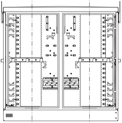
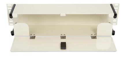
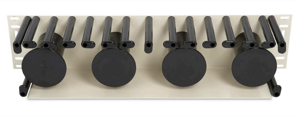
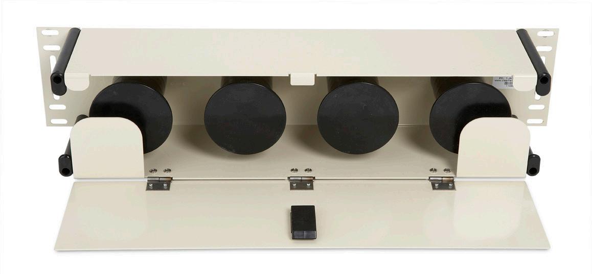
FieldSmart® Fiber Crossover Distribution System (FxDS)
Frame Kit - Top View Doors Open

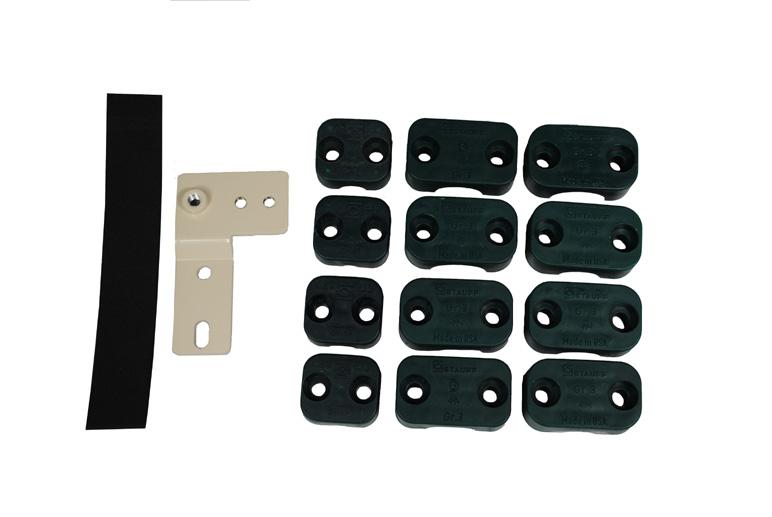
Adapter Plate Kit
Tie
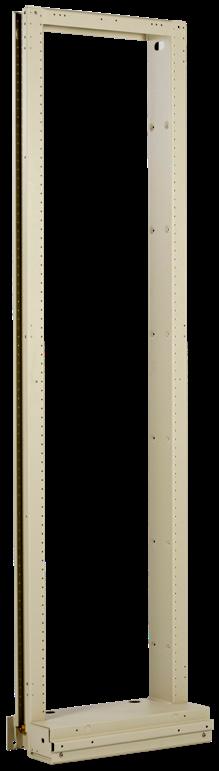
FieldSmart® Fiber Crossover Distribution System (FxDS) Standard Frames
Application
Frames are used for mounting equipment in central office, head end or data center applications.
Description
FieldSmart FxDS Standard Frames are available in 7’ (2133.60 mm) or 8’ (2438.40 mm) heights and in 19” or 23” (482.60 mm or 584.20 mm) widths. Frames are seismic-rated and come with an unequal flange. When used with FieldSmart FxDS Panels, they provide the highest port density in the industry - up to 1,728 ports in a 7’ (2133.60 mm) frame.
Features and Benefits
Integrity
• Designed to comply to Telcordia GR-449; Seismic rated (Zone 4) GR-63-CORE, Issue 4
• Made from high-strength, low alloy steel that can accommodate up to up to 500 lbs. (226.80 kg)
• EIA mounting - 1.75” (44.45 mm) and WECO mounting - 1” (25.40 mm)
• Front and rear of upright tapped for 12-24 screws Protection
• Frames can be ordered loaded with panels and cable management as a “rack and stack” solution
• Unequal flange
• Isolation pads are used to provide electrical isolation for FxDS standard seismic frames
• Interbay cable management panel optional
Access
• One frame size accommodates up to 1,728 or 1,152 ports in a PON environment, with full horizontal and vertical slack management support Investment
• Fully loaded or “grow-as-you-go” integrations allow the user choices to provide for cost containment as subscriber take-rates dictate
• Frame components are used throughout the network from inside plant to outside plant to access networks
Technical Specifications
Ratings Compliant to Telcordia GR-449
Cable Entry Clamp Location On-frame (Note: Cable clamps included with FxDS Patch Panels)
Material Steel
* Mounting hardware not included. Order separately.
FieldSmart® Fiber Crossover Distribution System (FxDS) Standard Frames
Pre-Configured Part Numbers
EIA Spacing
Part Number
FMA-A1A-E 19” (482.60 mm) seismic frame, 7’ (2133.60 mm) high, CLSD, EIA Universal (⅝” - ⅝” -
15.88 mm - 15.88 mm - 12.70 mm) hole pattern, almond white
FMA-A1C-E 19” (482.60 mm) seismic frame, 8’ (2438.40 mm) high, CLSD, EIA Universal (⅝” - ⅝” - ½”; 15.88 mm15.88 mm - 12.70 mm) hole pattern, almond white
FMA-A2A-E 23” (584.20 mm) seismic frame, 7’ (2133.60 mm) high, CLSD, EIA Universal (⅝” - ⅝” - ½”; 15.88 mm15.88 mm - 12.70 mm) hole pattern, almond white
FMA-A2C-E 23“ (584.20 mm) seismic frame, 8’ (2438.40 mm) high, CLSD, EIA Universal (⅝” - ⅝” -
15.88 mm15.88 mm - 12.70 mm) hole pattern, almond white
WECO Spacing Part Number Description
FMA-A1A
(482.60 mm)
Accessories FieldSmart® Fiber Crossover Distribution System (FxDS)
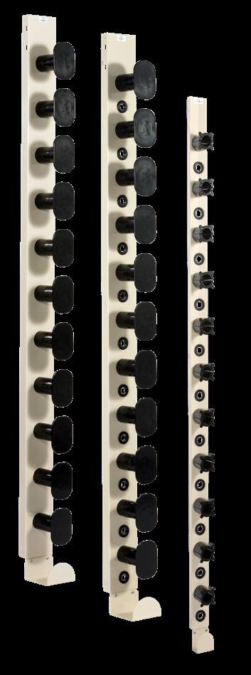
Interbay Cable Management Panels
Description
Interbay cable management is part of an overall fiber management system that includes frames and troughs. In addition to incremental slack take-up, the interbay provides a route-path between frames. Interbay cable management panels are ordered to match the height of the frame and are available in 7’ (2133.60 mm) and 8’ (2438.40 mm) versions. End guards are available for the end of a line up to minimize potential damage to jumpers. Interbay cable management is suggested for all fiber applications. Clearfield’s recommendation is to mount one interbay on both sides of each frame and place an interbay with end guard on each end of the lineup.
Configured Part Numbers
Disclaimer/Note: Paper configurator shown is for reference only and should not be used to configure a saleable product configuration. All options shown on paper configurators may not be available or compatible with other options listed. Please contact your Clearfield representative for assistance in product configurations.
Pre-Configured Part Numbers
FMA-EZA-PT
FxDS Interbay Cable Management Panel, 7’ H x 5” W (2133.60 mm x 127.00 mm), without end guards, with 1” (25.4 mm) grommeted cable pass through holes
FMA-EZA-PT-3I FxDS Interbay Cable Management Panel, 7’ H x 3” W (2133.60 mm x 76.20 mm), without end guards, custom with 1” (25.40 mm) grommeted cable pass through holes
FMA-FZA-PT
FMA-FZA-PT-3I
FxDS Interbay Cable Management Panel, 7’ H x 5” W (2133.60 mm x 127.00 mm), with end guards, custom with 1” (25.40 mm) grommet cable pass through holes
FxDS Interbay Cable Management Panel, 7’ H x 3” W (2133.60 mm x 76.20 mm), with end guards, with 1” (25.40 mm) grommet cable pass through holes
FMA-XXX-119 Kit, mounting bracket for FxDS Interbay, non-seismic, front mount
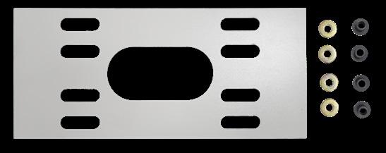
Isolation Pad
Description
The Isolation Pad provides isolation between the floor and the equipment rack.
Pre-Configured Part Numbers
Part Number Description
FMA-L1Z-SUB Isolation Pad Kit, 19” (482.60 mm) frame, 9.5” D x 22” W (241.30 mm x 558.80 mm)
FMA-L2Z-SUB Isolation Pad Kit, 23” (584.20 mm) frame, 9.5” D x 26” W (241.30 mm x 660.40 mm)
Floor Mount Hardware Kit
Part Number Description
009106 Floor Mounting Hardware Kit
FieldSmart® Fiber Crossover Distribution System (FxDS)
Accessories
Crossover Troughs
Description
Troughs are in integral part of the FieldSmart fiber management platform. When used properly, troughs provide a protected route path when running jumpers between equipment. Crossover Troughs are used when radius spools are not required. They are simply used to cross from one side of the frame to another or to reach another frame. They come standard with a front door for additional protection and improved appearance. Crossover Troughs are 3” or 5” high and available in 19” and 23” mounting.
Pre-Configured Part Numbers

Crossover Trough, 3” x 19” (76.20 mm x 482.60 mm) (no spools) FMA-B15 FxDS Crossover Trough, 5” x 19” (127.00 mm x 482.60 mm) (no spools)
FMA-B23 FxDS Crossover Trough, 3” x 23” (76.20 mm x 584.20 mm) (no spools)
FMA-B25 FxDS Crossover Trough, 5“ x 23” (127.00 mm x 584.20 mm) (no spools)
Active Gear Troughs
Description
Troughs are an integral part of the FieldSmart fiber management platform. When used properly, troughs provide a protected route path when running jumpers between equipment. Active Gear Troughs are equipped with nine radius fingers (19”) and 11 radius fingers (23”) on the open bottom. It is designed to be placed directly above or below an active gear chassis to manage slack and access of active gear cards and associated fiber ports. The Active Gear Troughs are 5” high and available in 19” and 23” mounting.
Pre-Configured Part Numbers
Slack Management Troughs
Description
Troughs are in integral part of the FieldSmart fiber management platform. When used properly, troughs provide a protected route path when running jumpers between equipment. Slack Management Troughs contain radius spools that add additional incremental slack take-up to the fiber management system. They come standard with a front door for additional protection and improved appearance. Slack Management Troughs are 5” deep and available in 5” and 7” heights and 19” and 23” mounting.
Pre-Configured Part Numbers
Part Number Description FMA-C15 FxDS Slack Management Trough, 5” x 19” (127.00 mm x 482.60 mm) (with spools) FMA-C25 FxDS Slack Management Trough, 5“ x 23” (127.00 mm x 584.20 mm) (with spools) FMA-C27 FxDS Slack Management Trough, 7” x 23” (177.80
FieldSmart® Fiber Crossover Distribution System (FxDS)
Accessories
Staging Plate Trough
Description
Troughs are an integral part of the FieldSmart fiber management platform. When used properly, troughs provide a protected route path then running jumpers between equipment. The Staging Plate Trough has two staging plates equipped with 36 positions each for “parking” optical splitter legs until they are ready to use.
Pre-Configured Part Numbers

FieldSmart® Fiber Crossover Multi Purpose (FxMP)
Frame Clamp Kit and Splice Deck Clamp Kit
Application
For on-frame patch and splice applications, the desire to clamp onto the frame rather than a FieldSmart FxMP Panel may be required to address proper cable sweep from the frame into the panel. The frame clamp can also be used to manage incoming cable at an additional location on the frame, when a more robust and rigid capture is required due to the O.D. size of the cable and the number of incoming cables.
Description
The FieldSmart FxMP Frame Clamp Kit comes with bracket for mounting onto the frame, clamp shells and mounting hardware. Mounts to 19” or 23” standing frames or cabinets.
Features and Benefits
• Can be used on any frame
• Comes with multiple size clamps
• Holds cable diameters up to 1” in diameter
Pre-Configured Part Numbers
Part Number
008140 Frame clamp kit, green polypropylene 018513
Saddle clamp, 1” diameter, grey polymide, VO 018514 Saddle clamp, ¾” diameter, grey polymide, VO 018515
Saddle clamp, ⅞” diameter, grey polymide, VO
FieldSmart® DIN Rail Cassette Mounting Kit
Application
The FieldSmart DIN Rail Cassette Mounting Kit easily mounts to any TS-35 (35 mm wide x 7.5 mm high or greater rail) industry standard DIN rail. The DIN rail clip “grips” the rail on both the top and bottom lips for tool-less installation. This is an ideal solution for applications requiring maximum system reliability and flexibility. It is perfectly suited for Transportation, Machine Building, Municipality, Oil and Gas Refinery, and Alternative Power Generation applications. It is also ideal for more general use in customer premise locations, enterprise networks and remote locations. Utilizing the Clearview ® Blue Cassette, the new DIN Rail Mounting Kit allows you to bring fiber management to areas where it was not able to be installed before.
Each cassette will provide 12 ports of connectivity for patch and splice (Clearfield’s incassette splicing solution), patch only (stubbed) or plug and play (MPO/MTP) configurations.
Description
The DIN Rail Cassette Mounting Kit includes the cassette mounting tray, bracket and rail mount clip. DIN rail tray and cassettes can be mounted vertically, horizontally or with adapters facing out with no specialty bulkheads needed. Up to two Clearview Cassettes can be mounted on one bracket. Brackets can be mounted next to each other for future growth.
Features and Benefits
Integrity
• Allows Clearview Cassettes to attach to DIN 35 mm slotted rail
• Modular and scalable Protection
• Durable steel plate
• Radius bend protection of all fiber cable within the blue cassettes Access
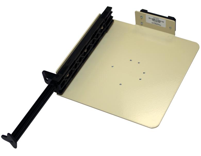
• Provides central location where external and internal wiring can be connected quickly and efficiently
• Associated devices can be mounted adjacent to each other, thus reducing the length of interconnect wiring
• 360° cassette mounting options Investment
• Reduces installation time
• Saves space - no need to panel mount all components
• Versatile mounting options
• Easy snap on/snap off capability
Technical Specifications FieldSmart
Port Density 12 or 24 ports
Cassette Types Supported Clearview ® Blue
Connector Types SC/UPC, SC/APC, LC/UPC, LC/APC
Pre-Configured Part Number
FieldSmart® Fiber Crossover Distribution System (FxDS)
Bulkhead Only
Application
Provides an interconnect or cross-connect environment for up to 288 ports of fiber.
Description
The FieldSmart FxDS Bulkhead is a high density, low maintenance bulkhead for use in a 19” (482.60 mm) or a 23” (584.20 mm) frame or cabinet. Utilizing the Clearview ® Cassette, FieldSmart FxDS Panels are intelligently designed to provide the user with superior fiber access and craft-friendly, radius protected, fiber management for routing and deploying fiber jumpers.
Stand Alone Bulkhead in a 19” or 23” (482.60 mm or 584.20 mm) Frame
When you already have the frame and want to add just a panel or two of incremental fiber management, the FxDS can be configured with front protection.
Stand Alone Panel in an OSP Active Cabinet

Make the crossover into the OSP with the identical product. Patch only environments are supported without additional components. The common architecture saves you time and money in reducing inventory costs and shorter training period.
Stand Alone Panel in a Data Cabinet
When you already have a data cabinet and simply need to add fiber management, the FxDS is configured without the front protection block, providing all the fiber protection you need without the added cost.
Features and Benefits
Integrity
• RUS listed
• Designed, tested and certifed to Telcordia GR-63 and GR-449
• Fiber cable is certified to Telcordia GR-20 & GR-409
• Optical component configurations use Telcordia GR-1221/1209 compliant devices
• Terminations designed, tested and certified to Telcordia GR-326
• Supports all industry standard singlemode and multimode connectors Protection
• Front protection cover is easily removable with no tools needed
• Individual radius fingers provide organized and intuitively managed fiber jumpers and minimize pile-up
• The Clearview Cassette houses critical circuits by 12-fiber sub-units or buffertubes Access
• Front access to pre-terminated assemblies with removable adapter plates for testing, cleaning and maintenance
• The entire 12-fiber Clearview Cassette is removable for hot-swap changes Investment
• Using the Clearview Cassette, all fibers are deployed in increments of 12, allowing users to scale from 12 ports to full configuration without additional equipment
FieldSmart® Fiber Crossover Distribution System (FxDS)
Bulkhead Only
Technical Specifications
FieldSmart FxDS Bulkhead
Ratings Compliant to Telcordia GR-63, GR-449, GR-20 and GR-409
Cassette Types Supported Clearview ® Blue, Clearview Black
Connector Types SC/UPC, SC/APC, LC/UPC, LC/APC, MPO
Cable Types Tight Buffer, Ribbon
Splice Capacity 12 splices in each Clearview Cassette
Front Protection 3.25” (82.6 mm) radius rods
Material Steel and aluminum with powder paint coating
Configured Part Numbers
1 Select Protection
D = 3.25" rods
M = Front protection only
R = Bulkhead only
2
Select Chassis Size *
J = 1.75" (44.45 mm)(1 RU) 24 port maximum (SC/LC)
E = 3.50" (88.90 mm)(2 RU) 72 port maximum (SC/LC)
K = 4" (101.60 mm) 96 port maximum (SC/LC)
G = 6" (152.40 mm) 144 port maximum (SC/LC)
H = 11" (279.40 mm) 288 port maximum (SC/LC) 2
3 Select Port Count
X X X = port count in increments of 12
4 Select Connector Style
A = SC/UPC
C = SC/APC
F = LC/UPC
H = LC/APC
5
0 = No fiber added
Select Panel Type
A = Patch only
D = Tie panel
G = Patch and splice
Note: All FxDS panels are designed to fit in 19" and 23" (482.60 mm and 584.20 mm) and are front load only. 7
1 = Singlemode - non-ribbon
2 = Singlemode - ribbon Select Mode / Type
6 Select Cable Construction
A = Indoor riser rated (IFC)
B = OSP (riser rated)
C = Indoor, plenum (IFC)
E = OSP (non-rated)
F = Patch and splice
M = OSP (armored)
Select Optional Cassette
B = Clearview Blue Cassette
Default = Clearview Black Cassette 8
XXXM or XXXF
XXXM = Length in meters
XXXF = Length in feet
* Max port counts are for SC and LC adapters.
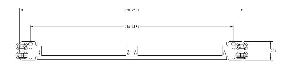
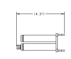


2RU Bulkhead 96-Port Bulkhead
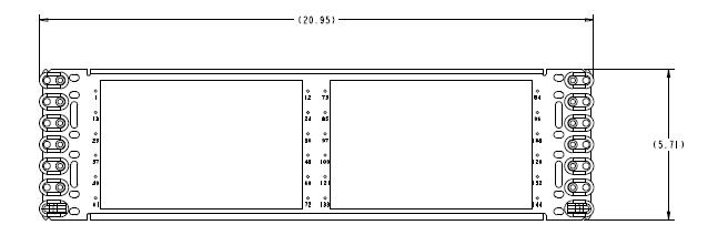
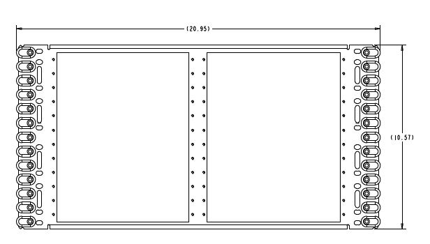
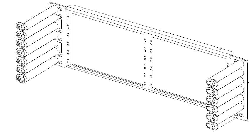
1RU Bulkhead Side View
144-Port Bulkhead
288-Port Bulkhead
Side View
FieldSmart® Fiber Crossover Multi Purpose (FxMP) Patch Panels
Application
Provides an interconnect or cross-connect environment for up to 288 SC ports or 576 LC ports of high density fiber for inside plant environments and outside FDH deployments.
Optical component chassis feature of the FxMP Panel is available for horizontally mounted modules.
Description
The FieldSmart FxMP Panel is a high density, low maintenance fiber distribution panel for use in a data style rack/cabinet, a 19” (482.60 mm) or a 23” (584.20 mm) frame. Utilizing the Clearview ® Cassette, FieldSmart FxMP Panels are intelligently designed to provide the user with superior fiber access and craft-friendly, radius protected, fiber management for routing and deploying fiber jumpers.
Stand Alone Panel in a 19” or 23” (482.60 mm or 584.20 mm) Frame
When you already have the frame and want to add just a panel or two of incremental fiber management, the FxMP is configured with front and rear protection blocks for complete slack storage and physical fiber protection.
Stand Alone Panel in an OSP Active Cabinet
Make the crossover into the OSP with the identical product. Patch only environments are supported without additional components, while a rear protection block enables patch and splice (Clearfield’s in-cassette splicing solution) configurations. The common architecture saves you time and money in reducing inventory costs and shorter training period.
Stand Alone Panel in a Data Rack/Cabinet
When you already have a data rack or cabinet and simply need to add fiber management, the FxMP is available to mount in this smaller footprint, providing all the fiber protection you need without the added cost. Available in black.
Optical Component Chassis

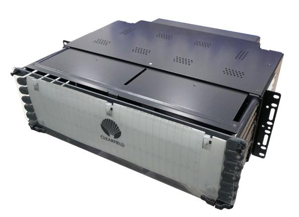
An optical component chassis is mounted in a rack and holds optical components modules. Fiber jumper management is provided from the front of the optical component module to the interbay cable management panels. Optical components are splitters or WDM’s that are housed in the flexible Clearview Cassette. The FieldSmart modules require an Optical Component Chassis to house the modules in a frame.
Features and Benefits
Integrity
• RUS listed
• Designed, tested and certifed to Telcordia GR-63 & GR-1089 NEBS Level 3
• Fiber cable is certified to Telcordia GR-20 & GR-409
• Terminations designed, tested and certified to Telcordia GR-326
• Supports all industry standard singlemode connectors
Protection
• Front cover is easily removable and installation of cassettes is simple with no tools needed
• Individual radius fingers provide organized and intuitively managed fiber jumpers and minimize pile-up
• Slide rails for cassettes provide a stable attachment utilizing the cassette T-rail, and are incorporated into the rear protection of panels
• Pre-terminated OSP buffer tubes are protected by bend-limited tubing and have their slack stored inside the panel to protect against environmental and human damage
• The top metal protective cover slides out for top protection over the fiber cables and can sit in 3 positions: closed, open 3.25” (82.55 mm) and open 4.77” (121.16 mm)
Access
• Front access to pre-terminated assemblies with removable adapter plates for testing, cleaning and maintenance
• The entire 12-fiber Clearview Cassette is removable for hot-swap changes
• Front and rear access to panel
• New larger designation cards provide greater writing area for standard and high density panels
• Reversible Mounting Ears provide added flexibility
Top Protection - Closed
Top Protection - Black
FieldSmart® Fiber Crossover Multi Purpose (FxMP)
Patch Panels
Investment
• Using the Clearview Cassette, all fibers are deployed in increments of 12, allowing users to scale from 12 ports to full configuration without additional equipment
Optical Component Investment
• Virtually any combination of split ratios and number of components can be achieved in one of the four Clearview Cassette sizes.
• An economical dense and user-friendly solution for deploying splitters or WDM’s in a central office design.
• 1RU optical components available for smaller, limited deployments.
• Horizontal mounting versions of the FieldSmart FxMP Panel with Optical Component Chassis capabilities are available in five sizes to accommodate any size project.
• Allow for grow-as-you-go design to reserve rack space for future growth.
Patch Panel Technical Specifications
FieldSmart
Ratings Compliant to Telcordia GR-63, GR-1089, GR-449, GR-20 and GR-409
Cassette Types Supported Clearview ® Blue with 1 mounting tab
Connector Types SC/UPC, SC/APC, LC/UPC, LC/APC, MPO
Cable Types Indoor Riser, Indoor Plenum, Indoor/Outdoor, Outdoor (Riser/Non-Rated), Outdoor Armored (Riser/NonRated), FieldShield ®
Splice Capacity 12-24 splices in each Clearview Cassette
Storage Capacity One meter of 250 μm fiber
Front Protection 3.25” (82.6 mm) or 4.77”
Material Steel and aluminum with powder paint coating
Optical Component Chassis Technical Specifications
Ratings Fully certified to NEBS Level 3 Telcordia GR-63, GR-1089, GR-449, GR-20 and GR-409
Cassette Types Supported Clearview ® Blue, Clearview xPAK
Material Steel and aluminum with almond powder coating. Also available in black.
FieldSmart® Fiber Crossover Multi Purpose (FxMP)
Patch Panels
FieldSmart Chassis Capacity - Number of Components
Configured Part Numbers - Patch and Splice/Optical Component Chassis
Disclaimer/Note: Paper configurator shown is for reference only and should not be used to configure a saleable product configuration. All options shown on paper configurators may not be available or compatible with other options listed. Please contact your Clearfield representative for assistance in product configurations.
Select Chassis Size *
J = 1.75" (44.45 mm)(1 RU) 24/48 port maximum (SC/LC)
E = 3.50" (88.90 mm)(2 RU) 72/144 port maximum (SC/LC)
K = 4" (101.60 mm) 96/192 port maximum (SC/LC)
G = 6" (152.40 mm) 144/288 port maximum (SC/LC)
H = 11" (279.40 mm) 288/576 port maximum (SC/LC)
Select Panel Type
B = Patch and splice
C = MPO (12 fiber)
D = Tie
F = HD Patch and Splice
J = HD Tie
A = Almond 3.25" (82.55 mm)
B = Almond 4.77" (121.16 mm)
C = Black 3.25" (82.55 mm)
D = Black 4.77" (121.16 mm)
4 Select Port Count
X X X = port count in increments of 12 X X X = port count in increments of 24 (HD Version)
Select Mode / Type
Singlemode - ribbon
Select Jacket Construction
F = Loose Tube
Z = N/A
Select Rear Protection
A = Slack Basket
B = Rear Cover
FieldSmart® Fiber Crossover Multi Purpose (FxMP) Patch Panels
Configured Part Numbers - Patch Only
Disclaimer/Note: Paper configurator shown is for reference only and should not be used to configure a saleable product configuration. All options shown on paper configurators may not be available or compatible with other options listed. Please contact your Clearfield representative for assistance in product configurations.
J = 1.75" (44.45 mm)(1 RU) 24/48 port maximum (SC/LC)
E = 3.50" (88.90 mm)(2 RU) 72/144 port maximum (SC/LC)
K = 4" (101.60 mm) 96/192 port maximum (SC/LC)
G = 6" (152.40 mm) 144/288 port maximum (SC/LC)
H = 11" (279.40 mm) 288/576 port maximum (SC/LC)
Select Panel Type
A = Patch Only
E = HD Patch Only (LC)
3 Select Color and Rod Size
A = Almond 3.25" (82.55 mm)
B = Almond 4.77" (121.16 mm)
C = Black 3.25" (82.55 mm)
D = Black 4.77" (121.16 mm)
4 Select Port Count
X X X = port count in increments of 12
X X X = port count in increments of 24 (HD version)
Configurations
FieldSmart
5 Select Connector Style
A = SC/UPC
C = SC/APC
F = LC/UPC
H = LC/APC
Z = None
Select Mode / Type
0 = No Fiber
1 = Singlemode - non-ribbon
2 = Singlemode - ribbon
7 Select Cable Construction
A = Indoor riser rated (IFC)
B = OSP (riser rated, indoor/outdoor)
C = Indoor, plenum (IFC)
E = OSP (non-rated)
F = Patch and splice
M = OSP (armored)
Z = N/A
Select Rear Protection
A = Slack Basket B = Rear Cover
Select Cable Exit **
or XXXF
= Length in meters
= Length in feet
FieldSmart® Fiber Crossover Multi Purpose (FxMP)
Patch Panels
Configurations
FieldSmart Fiber Crossover Multi Purpose (FxMP) Top Views
Bulkhead with Slack Basket - Top View Shown with Short Rods (3.25”)
FieldSmart Fiber Crossover Multi Purpose (FxMP) 24 Port Fiber Panels
FieldSmart Fiber Crossover Multi Purpose (FxMP) 72 Port Fiber Panels
Bulkhead with Rear Door - Top View Shown with Short Rods (3.25”)
FieldSmart® Fiber Crossover Multi Purpose (FxMP) Patch
Panels
Configurations
FieldSmart Fiber Crossover Multi Purpose (FxMP) 96 Port Fiber Panels
FieldSmart Fiber Crossover Multi Purpose (FxMP) 144 Port Fiber Panels
FieldSmart Fiber Crossover Multi Purpose (FxMP) 288 Port Fiber Panels
FieldSmart® Fiber Crossover Multi Purpose (FxMP) Tie Panels
Application
The FieldSmart FxMP Tie Panel provides an in the field configured interconnect or crossconnect environment for 12 to 288 ports of high density fiber in central office/headend environments.
Description
The FieldSmart FxMP Tie Panel is a high density, low-maintenance fiber distribution panel for use in a 19” or 23” (482.60 mm or 584.20 mm) frame. Tie panels are intelligently designed to provide the user with superior fiber access, utilizing craft-friendly radius protected fiber management for routing and deploying fiber jumpers or multi-fiber cables, on both sides of the adapter plate for cross-connect environments. They use a removable adapter plate that mounts on the right side or left side of the panel.
Features and Benefits
Integrity
• RUS listed
• Designed, tested & certified to Telcordia GR-63 & GR-1089 NEBS Level 3
• Designed to comply with Telcordia GR-449
• Certified to Telcordia GR-20 & GR-409
• Optical component configurations use Telcordia GR 1221/1209 compliant devices
• Terminations designed, tested and certified to Telcordia GR-326
• Supports all industry standard singlemode and multimode connectors Protection
• Front cover is easily removable with no tools needed
• Cable clamp protects against twisting and pistoning at the assembly breakout point
• Top metal protective cover slides out for top protection over the fiber cables Access
• Front access with removable adapter plates for testing, cleaning and maintenance
• Front and rear access to panel Investment
• Panel sizes available in 1.75” (44.45 mm) 1RU (24 ports), 3.50” (88.90 mm) 2RU (72 ports), 4” (101.60 mm) (96 ports), 6” (152.40 mm) (144 ports) and 11” (279.40 mm) (288 ports) (Note: all port counts based on SC adapter style)
• Industry-leading density, supporting 288 ports SC in 11” (279.40 mm)
• 19” and 23” (482.60 mm and 584.20 mm) reversible mounting brackets for flexibility
Top Protection - Closed
Bulkhead with Slack Basket - Top View Shown with Short Rods (3.25”)
FieldSmart® Fiber Crossover Multi Purpose (FxMP) Tie
Panels
Technical Specifications
Ratings Fully certified to Telcordia GR-63 and GR-1089 (NEBS 3), GR-449, GR-20 and GR-409
Cassette Types Supported N/A
Connector Types SC/UPC, SC/APC, LC/UPC, LC/APC
Splice Capacity N/A
Storage Capacity N/A
Front Protection 3.25” (82.55 mm) and 4.75” (120.65 mm) radius fingers
Material Steel and aluminum with almond or black powder coating
Configured Part Numbers
Disclaimer/Note: Paper configurator shown is for reference only and should not be used to configure a saleable product configuration. All options shown on paper configurators may not be available or compatible with other options listed. Please contact your Clearfield representative for assistance in product configurations.
1 Select Chassis Size
J = 1.75" (44.45 mm)(1 RU) 24/48 port maximum (SC/LC)
E = 3.50" (88.90 mm)(2 RU) 72/144 port maximum (SC/LC)
K = 4" (101.60 mm) 96/192 port maximum (SC/LC)
G = 6" (152.40 mm) 144/288 port maximum (SC/LC)
H = 11" (279.40 mm) 288/576 port maximum (SC/LC)
2 Select Panel
D = Tie
Tie Panel Plates
= Black 4.77" (121.16 mm)
4 Select Port Count
X X X = port count in increments of 12 X X X = port count in increments of 24 (HD Version)
5 Select Connector Style
A = SC/UPC
C = SC/APC
F = LC/UPC
H = LC/APC
6
Select Rear Protection
A = Slack Basket
B = Rear Cover
Tie plates will attach to the panel in a similar manner to cassettes, except instead of sliding a T-rail into one of the panel’s slide rails, the hook on the end of the tie plate will insert into the front of the slide rail. Press on the push/pull plunger to secure the tie plate.
Note: Images may not match product received. Fiber routing and protection will remain the same.
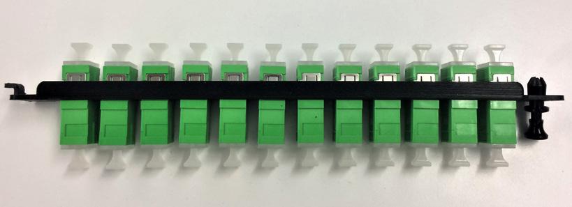
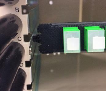

FieldSmart® Fiber Crossover Multi Purpose (FxMP)
Tie Plate Kit
Pre-Configured Part Numbers - Standard
Part Number
Description
FMA-XXX-169-L Adapter Plate, FxMP, SM, 12 x SC/UPC, Left Side
FMA-XXX-169-R Adapter Plate, FxMP, SM, 12 x SC/UPC, Right Side
FMA-XXX-170-L Adapter Plate, FxMP, SM, 12 x SC/APC, Left Side
FMA-XXX-170-R Adapter Plate, FxMP, SM, 12 x SC/APC, Right Side
FMA-XXX-171-L Adapter Plate, FxMP, SM, 12 x LC/UPC, Left Side
FMA-XXX-171-R
Adapter Plate, FxMP, SM, 12 x LC/UPC, Right Side
FMA-XXX-172-L Adapter Plate, FxMP, SM, 12 x LC/APC, Left Side
FMA-XXX-172-R Adapter Plate, FxMP, SM, 12 x LC/APC, Right Side
Pre-Configured Part Numbers - High Density
Part Number Description
FMA-XXX-173-L
Adapter Plate, FxMP, SM, 24 x High Density LC/UPC, Left Side
FMA-XXX-173-R Adapter Plate, FxMP, SM, 24 x High Density LC/UPC, Right Side
FMA-XXX-174-L
FMA-XXX-174-R
Adapter Plate, FxMP, SM, 24 x High Density LC/APC, Left Side
Adapter Plate, FxMP, SM, 24 x High Density LC/APC, Right Side
FieldSmart® Fiber Crossover Distribution System (FxDS)
Optical Component Chassis (OCC)
Application
The FieldSmart FxDS Optical Component Chassis (OCC) is used for housing optical component modules. The FxDS Optical Component Chassis is available FOR horizontally mounted and LGX vertically mounted modules. These products are needed when optical components are required. They are typically used in CATV headends and telephone company central offices.
Description
An optical component chassis is mounted in a rack and holds optical components modules. Fiber jumper management is provided from the front of the optical component module to the interbay cable management panels. Optical components are splitters or WDM’s that are cassette or metal LGX housing based. Optical components can be housed in the flexible Clearview ® Cassette or in one of our four sizes of LGX style modules. The LGX and FieldSmart ® modules require an Optical Component Chassis to house the modules in a frame. The 1RU splitter “pizza box” does not require a separate chassis and is available in 19” or 23” (482.60 mm or 584.20 mm) mounting versions.
Features and Benefits
Integrity
• RUS listed
• Compliant to Telcordia GR-449
• Supports all industry standard singlemode and multimode connectors
• May be ordered as a “bulkhead only” application without rear protection Protection
• Optional ruggedized Lexan front cover
• Optional rear protection module available for additional protection
• Non-removable adapter plates Access
• Front and rear access to panel Investment
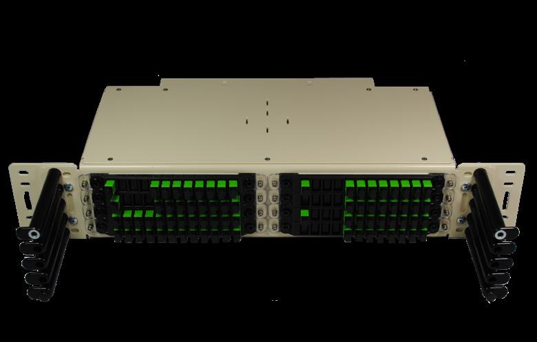
• Virtually any combination of split ratios and number of components can be achieved in one of the four FieldSmart cassette sizes
• An economical, dense and user-friendly solution for deploying splitters or WDM’s in a central office design
• 1RU optical components available for smaller, limited deployments
• Clearfield supports legacy splitter deployments by offering optical components in an LGX footprint
• Horizontal mounting versions of the FieldSmart FxDS OCC are available in five sizes to accommodate any size project
• Available for both 19” or 23” (482.60 mm or 584.20 mm) mounting
• Chassis incorporates the superior fiber management system of the FieldSmart FxDS panel line
• Allows for a “grow-as-you-go” design to reserve rack space for future growth
Accessories
• xPAK
• LGX/MOC
• Blank plates
Horizontal Orientation
FieldSmart® Fiber Crossover Distribution System (FxDS)
Optical Component Chassis (OCC)
Technical Specifications
FieldSmart FxDS Optical Component Chassis
Clearview Cassette: 2
Dimensions
Ratings Compliant to Telcordia GR-449
Cassette
Configured Part Numbers
1 Frame Size and Chassis Type
K = 19" and 23" (482 60 mm and 584 20 mm)
FxDS horizontal (Clearview Cassettes )
M = 19" and 23" (482 60 mm and 584 20 mm)
FxDS LGX vertical cassettes
Protection Modules
7 = No front load protection
8 = Front protection only 9 = Rear protection only A = Both front and rear protection
Number of Slots
SmartRoute Infinity Panel 1RU Panel
Application
The SmartRoute Infinity 1RU Panel is designed to simplify and speed up fiber installations when landing 24 to 48 fibers in any interconnect or cross-connect environment. Clearfield’s SmartRoute Infinity Panel combines cable wrap technology and MPO connectorization in a single panel to help relieve cable congestion, simplify ordering and eliminate incorrect cable lengths for IFC cable assemblies while saving labor and installations costs.
The SmartRoute Infinity Panel combines two separate, but critical fiber connectivity elements: The intermediate fiber panel and the IFC fiber cable assembly into one easy-to-deploy unit. If your network is comprised of both singlemode and multimode fiber, the Infinity Panel can be configured with singlemode fiber on one rod assembly and multimode fiber on the other rod assembly.
Description
The SmartRoute Infinity Panel combines micro-distribution cable, rod technology and MPO connectorization in a single panel to help relieve cable congestion, simplify ordering and eliminate incorrect cable lengths for IFC cable assemblies. It also provides savings on labor and installation costs. The Infinity Panel contains two internal rod assemblies that can hold up to 100 feet each of IFC cable. The panel can provide 24 SC or 48 LC connections in front and MPO, plug-and-play, SC/LC breakouts for pigtails on the cabled far end.
Features and Benefits
Integrity
• Terminations designed, tested and certified to Telcordia GR-326
• Clearfield FiberDeep Guarantee: 0.2dB insertion loss or less, exceeding industry standards
• Supports all industry standard singlemode and multimode connectors
Protection
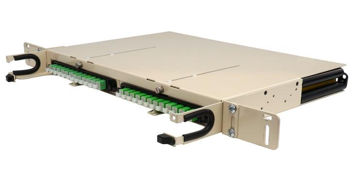
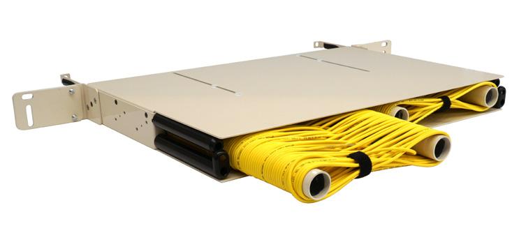
• Infinity Panel rod technology allows an installer to payout the exact amount of cable required from the panel, leaving the remaining slack safely stored within the panel
• Individual radius fingers organize and intuitively manage fiber jumpers
• Removable front protection provides physical fiber protection, reducing service interruptions
Access
• Straight forward, simple design means installation crews spend less time figuring out how to deploy
• Dual rod assemblies can be utilized independently
• Removable front adapter plates provide access to preterminated assemblies for testing, cleaning and maintenance
Investment
• Pre-connectorized options eliminate splice labor and speed network construction
• Rod assemblies reduce upfront deployment costs by simplifying site survey inspections, reducing labor hours and streamlining cable deployment
SmartRoute Infinity Panel
1RU Panel
Technical Specifications
SmartRoute Infinity Panel 1RU Panel
Dimensions
Mounting Options
Front Protection
1.70”H x 16.93”W x 14.53”D (43.18 mm x 430.02 mm x 369.06 mm)
19” mounting ear with 23” extension
Polycarbonate front cover with attached designation card
Connector Types SC and LC
Port Density
24 ports = SC/UPC or SC/APC; 48 ports = LC/UPC or LC/APC
Cabled End SC and LC breakouts, MPO
Maximum Internal Cable Length
2 Rod Assemblies with 3mm 12-fiber micro cable = 100 feet per rod assembly/200 feet
Configured Part Numbers
Disclaimer/Note: Paper configurator shown is for reference only and should not be used to configure a saleable product configuration. All options shown on paper configurators may not be available or compatible with other options listed. Please contact your Clearfield representative for assistance in product configurations. S R
Connector Left Side or Single Module
1
2 = Dual Module Slots
3 = Single Module Slot
2 Module Assembly
A = SC/UPC
C = SC/APC
1 = 12
2 = 24 (LC only )
Z = None
A = SC/UPC
C = SC/APC
F = LC/UPC Duplex
H = LC/APC Duplex Left
3 Left Mode & Type
1 = SM Stranded Non-ribbon
7 = MM OM3 Laser Optimized
4 Left Jacket Construction
5 = Indoor Riser Microcable (SM only )
Y = Indoor Micro Distribution Cable (MM only)
5 Left Port Count
1 = 12
2 = 24 (SC-Single , LC-Dual)
4 = 48 (LC Single Module Only)
6 Left Rear Connector Type
A = SC/UPC
C = SC/APC
E = LC/UPC simplex
G = LC/APC simplex
R = MPO female 24 port
6 = MPO female 12 port
A = SC/UPC
C = SC/APC
F = LC/UPC Duplex
H = LC/APC Duplex
Z = None Right Front Panel Connector Type
E = LC/UPC Simplex
G = LC/APC Simplex
R = MPO Female 24 Port
1 = SM Stranded Non-ribbon 7 = MM OM3 Laser Optimized Z = None Right Mode & Type 13 14 Right Port Count
6 = MPO Female 12 Port Right Rear Connector Type 15 Right Rear Breakout
B = 1 meter
C = ½ meter
P = Pulling Eye
Z = None 16 Right Rear Upjacketing
A= 900 um
B = 2 mm
Z = None 17 Rear Spool Right Side Length
2 = 50 feet
4 = 100 feet
Z = None
5 = Indoor Microcable (SM Only)
Y = Indoor Micro Distribution Cable (MM Only)
Z = None Right Jacket Construction
FieldSmart® Small Count Delivery (SCD) Panel - Rack Mount
Application
The FieldSmart Small Count Delivery (SCD) Panel for a rack is a cost-effective way to provide fiber management protection in interconnect or cross-connect environments when landing a small number of fibers. It provides connectivity for Clearview ® Blue Cassettes and xPAKs in a 1RU footprint.
Description
The FieldSmart SCD Panel provides the ability to rack-mount Clearview devices in a single rack unit. The 2 slot panel version supports the 12 port Clearview Cassette or the two port, four port or six port Clearview xPAK in a single rack unit. The 3 slot panel version supports up to 3 Clearview xPAKs in a single rack unit. The product is available as either a 19” or 23” (482.60 mm or 584.20 mm) rack-mount unit. The FieldSmart SCD 1RU is intelligently designed to provide the user with superior fiber access while using craft-friendly radius protected fiber management for routing and deploying fiber jumpers.
Features and Benefits
Integrity
• RUS listed
• Terminations designed, tested and certified to Telcordia GR-326
• Designed to comply to Telcordia GR-449, GR-20, GR-409 anf GR-1209/1221
• Clearview devices support all industry standard singlemode and multimode connectors Protection
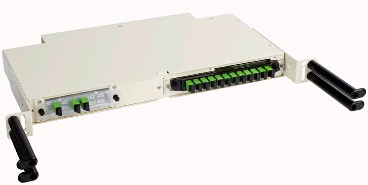
• Individual radius fingers provide organized and intuitively managed fiber jumpers, minimizing pile up Access
• Clearview devices are removable for hot-swap changes
• Front and rear access to panel
• Splicing integrated within the cassette for optimal protection and space utilization Investment
• Fiber protection is optimized within the Clearview device
• FieldSmart SCD extends this protection with minimal added cost or overhead
SCD-X1RU-RM
SCD-X1RU-RM-3
Rack Mount SCD Panel with xPAK and Clearview Blue Cassette
FieldSmart® Small Count Delivery (SCD) Panel - Rack Mount
Technical Specifications
FieldSmart 1RU Small Count Delivery Panel - Rack
Dimensions
1.70” H x 17.24” W x 9.23” D (43.18 mm x 437.90 mm x 234.44 mm)
Ratings Compliant to Telcordia GR-449
Port Density
24 SC or 48 LC (cassette version), 12 SC or 36 LC (xPAK version)
Cassette Types Supported Clearview Blue, Clearview xPAK, or mix and match
Connector Types SC/UPC, SC/APC, LC/UPC, LC/APC, MPO
Cable Types
Indoor Riser, Indoor Plenum, Indoor/Outdoor, Outdoor (Riser/Non-Rated), Outdoor Armored (Riser/NonRated), FieldShield ®
Splice Capacity 12-24 splices in each Clearview Cassette
Storage Capacity
One meter of 900 μm fiber
Material Steel and aluminum with almond powder coating
Pre-Configured Part Numbers
Part Number Description
SCD-X1RU-RM
SCD-X1RU-RM-3
008145
FMA-XXX-189
FieldSmart SCD 1RU Rack Mount; 2 slots (cassette and xPAK compatible)
FieldSmart SCD 1RU Rack Mount, 3 slots (xPAK compatible only)
Blank Plate for 2 Slot Panel (each)
Blank Plate Kit for xPAK 3 Slot Panel (each)
FieldSmart® Small Count Delivery (SCD) Panel - Cabinet Mount
Application
The Small Count Delivery Panel for a cabinet is a cost-effective way to provide fiber management protection in interconnect or cross-connect environments when landing a small number of fibers. It provides connectivity for Clearview ® Blue Cassettes and xPAKs in a 1RU footprint.
Description
The FieldSmart SCD Panel for a cabinet provides a cost-effective means to cabinet-mount up to two Clearview devices: the 12 port Clearview Cassette or the two port, four port or six port Clearview xPAK in a single rack unit. The product is available as either a 19” or 23” (482.60 mm or 584.20 mm) data cabinet-mount unit. The FieldSmart SCD 1RU is intelligently designed to provide the user with superior fiber access while using craft-friendly radius protected fiber management for routing and deploying fiber jumpers.
Features and Benefits Integrity
• RUS listed
• Terminations designed, tested and certified to Telcordia GR-326
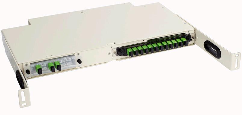
• Clearfield ® FiberDeep ® Guarantee: 0.2 dB insertion loss or less, exceeding industry standards
• Designed to comply to Telcordia GR-449, GR-20, GR-409 and GR-1221/1209
• Clearview devices support all industry standard singlemode and multimode connectors Protection
• Individual radius fingers or pass-through radius routing provides organized and intuitively managed fiber jumpers, minimizing pile up Access
• Clearview devices are removable for hot-swap changes
• Front and rear access to panel
• Splicing integrated within the cassette for optimal protection and space utilization Investment
• Fiber protection is optimized within the Clearview device
• FieldSmart SCD extends this protection with minimal added cost or overhead
Technical Specifications
Cable Types Indoor Riser, Indoor Plenum, Indoor/Outdoor, Outdoor (Riser/Non-Rated), Outdoor Armored (Riser/NonRated), FieldShield
Splice Capacity 12 splices in each Clearview Cassette
Storage Capacity One meter of 900 μm fiber
Pre-Configured Part Numbers
Cabinet Mount SCD Panel
Indoor 144 Fiber Entrance Cabinet (FEC)
Application
The wall-mountable StreetSmart ® Indoor 144-Port Fiber Entrance Cabinet (FEC) provides off-frame splicing, storage and protection for the central office, headend or enterprise networks. Fiber Entrance Cabinets are typically placed in the fiber entrance room and used to transition OSP fiber sheaths to IFC cabling.
Description
The StreetSmart FEC is built on a modular platform scaling 144 heat shrink fusion (HSF) or 432 mass fusion (ribbon) fiber splices at a time. Multiple entry/exit points allow for multiple distribution and OSP fiber sheaths to enter into the FEC from top or bottom and transition from conduit, overhead fiber tray or raised flooring. The cabinet holds six 24-fiber splice trays, allowing the user access and the ability to prep away from the cabinet. Intuitive buffer tube and sub-unit slack routing prevents cable tie-in with a clockwise routing scheme to allow quick and easy re-entry after initial deployment or to add additional capacity. Multiple cable entry/exit locations are provided on the top and bottom of the housing supporting cable diameters of up to one inch. A lockable door allows for easy access with minimal swing clearance needed for tight aisle clearances.
Features and Benefits
Integrity
• Industry standard splice tray
• Sturdy construction using 18 gauge steel
Protection
• Hinged doors, with removable hinge pin provides extra stability

• Ruggedized cable clamps protect against twisting and pistoning at the assembly breakout point
• Full bend-radius protection throughout cabinet
Access
• Multiple entry/exit points allow distribution and OSP fiber sheaths to enter from top or bottom
• Cable entrance plates support cable diameters up to one inch
• Removable splice trays provide technicians access to prep outside of the cabinet
• Intuitive, clockwise fiber management routing scheme prevents cable tie-in
• Ability to store up to 20 feet total of 144 loose tube cable
Investment
• Splice trays support a maximum of up to 24 loose tube splices or six 12F mass fusion (72) fibers
StreetSmart®
Indoor 144 Fiber Entrance Cabinet (FEC)
Technical Specifications
StreetSmart Indoor 144 FEC
Dimensions
10.4”H x 15.3”W x 6.3”D
Ratings Compliant to GR-449
Cable Types
Splice Capacity
Storage Capacity
Material
Indoor Riser, Indoor Plenum, Indoor/Outdoor, Outdoor (Riser/Non-Rated), Outdoor Armored (Riser/NonRated), FieldShield ®
144 Heat Shrink Fusion (HSF) or 432 Mass Fusion (MF) Ribbon Splices
One meter of 900 um fiber and five meters of exposed buffer tube
18 gauge cold rolled steel with almond powder coating
Pre-Configured Part Numbers
StreetSmart® Indoor 288 Fiber Entrance Cabinet (FEC)
Application
The StreetSmart ® Indoor 288-Port Fiber Entrance Cabinet (FEC) provides off-frame splicing for the central office, headend or remote hut. Fiber Entrance Cabinets are typically placed in the fiber entrance room and used to transition OSP fiber sheaths to IFC cabling.
Description
The StreetSmart FEC is built on a modular platform scaling 288 heat shrink fusion (HSF) or 864 mass fusion (ribbon) fiber splices at a time. Multiple entry/exit points allow for multiple distribution and OSP fiber sheaths to enter into the FEC from top, bottom or sidewalls and transition from conduit, overhead fiber tray or raised flooring. A removable splice block, holding twelve 24-fiber or 48 (loose tube only) fiber splice trays allows the user access and the ability to prep away from the cabinet. Intuitive buffer tube and sub-unit slack routing prevents cable tie-in with a clockwise routing scheme to allow quick and easy re-entry after initial deployment or to add additional capacity. If vertical real estate is available, the FEC can be ganged together, in modular fashion, allowing scalability up to 864-fiber splices and beyond.
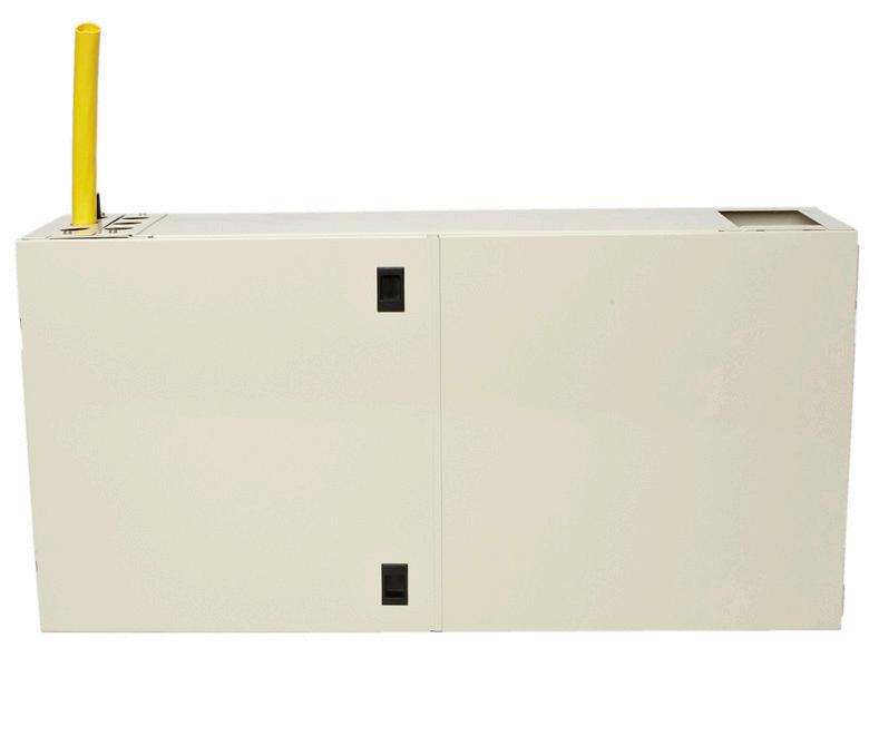
Each cable entrance plate will support cable diameters up to one inch. Lockable cupboard style doors allow for easy access with minimal swing clearance needed for tight aisle clearances.
Features and Benefits Integrity
• Industry standard splice tray
• Sturdy construction using 16 gauge steel Protection
• Piano hinged doors, with removable hinge pin provides extra stability
• Ruggedized cable clamps protect against twisting and pistoning at the assembly breakout point
• Full bend-radius protection throughout cabinet Access
• Multiple entry/exit points allow distribution and OSP fiber sheaths to enter from top, bottom or sidewalls
• Cable entrance plates support cable diameters up to one inch
• Removable splice trays provide technicians access to prep outside of the cabinet
• Intuitive, clockwise fiber management routing scheme prevents cable tie-in
• Ability to store five meters of exposed buffer tubes
• Removable hinge pin allows for easy door removal Investment
• Splice trays supports both loose tube and ribbon constructions for single and mass fusion (ribbon) splicing
- Maximum of 48 splice per tray LT (576)
- Maximum of 72 splice per tray RB (864)
• FECs can be ganged together in a modular fashion when vertical real estate space permits
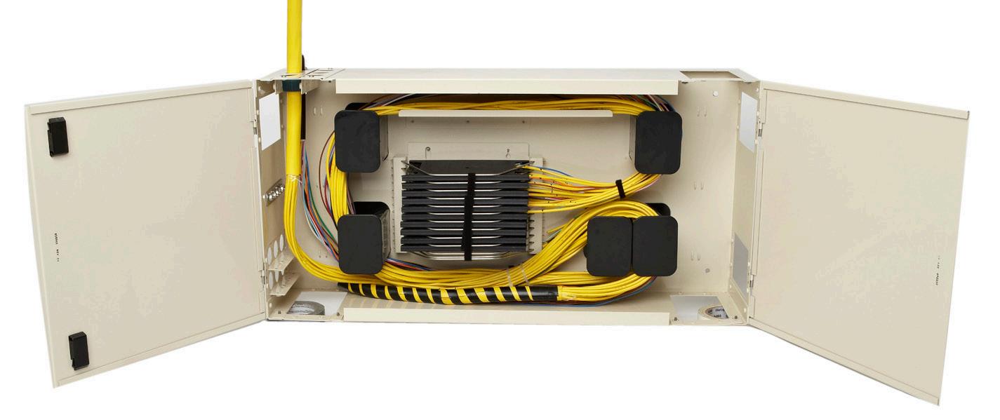
StreetSmart® Indoor 288 Fiber Entrance Cabinet (FEC)
Technical Specifications
StreetSmart Fiber Entrance Cabinet
Dimensions 17.5” H x 34.5” W x 8.25” D (444.50 mm x 876.30 mm x 209.55 mm)
Ratings Designed to comply to Telcordia GR-449
Cable Types
Indoor Riser, Indoor Plenum, Indoor/Outdoor, Outdoor (Riser/Non-Rated), Outdoor Armored (Riser/NonRated), FieldShield ®
Splice Capacity 576 heat shrink fusion (HSF) loose tube or 864 mass fusion (MF) ribbon splices
Storage Capacity One meter of 900 μm fiber and five meters of exposed buffer tube
Material 16 gauge cold rolled steel with almond powder coating
Pre-Configured Part Numbers
Clamp Kit (includes four clamp plates, four ½” (12.70 mm) clamps, four 1” (25.40 mm) clamp plugs and appropriate hardware)
Introduction to Outside Plant Solutions
FieldSmart ® Products
The goal of today’s outside plant deployment is to cost-effectively consolidate and distribute fiber deeper into the network.
At Clearfield ®, Outside Plant FieldSmart products are designed from the ground up based on field-proven experience and offer truly unique solutions for today’s FTTx rapid deployment demands. FieldSmart Fiber Scalability Center (FSC) Cabinets use the same modular components as FieldSmart FxDS Frame Kits deployed in the Inside Plant, allowing technicians the ease of working with a single fiber management platform regardless of Inside or Outside Plant deployment.
FieldSmart Fiber Distribution Hub (FDH) Cabinets
The FieldSmart Fiber Distribution Hub (FDH) line of products sets the bar for fiber access, protection and density among outside plant cabinets for PON, cross-connect or hub collapse environments. With the Clearview ® Cassette as its foundation, the FieldSmart FDH line uses the same components as the FieldSmart Frames and Panels deployed in the inside plant. This enables service providers to standardize on a single building block, allowing a single fiber management component to be deployed for both environments. This provides technicians the ease of working with a single fiber management platform regardless of inside or outside plant deployment - saving training and installation time.
• In a PON configuration, the FDH Cabinet is the complete solution for managing 144, 288, 432, 576 or 864 fibers for outside plant FTTx applications.
• In a cross-connect configuration, 432 or 864 feeder/distribution ports can be deployed and the cabinet supports a user defined feeder-to-distribution ratio without any real estate penalty.
• The FieldSmart Hub Collapse Cabinet (HCC) is designed for the cable operator looking to separate their passive infrastructure from the electronics without the need for standard hub architecture and it reduces operating costs associated with moves, adds and changes.
FieldSmart Fiber Active Cabinets (FAC)
FieldSmart Fiber Active Cabinet (FAC) outdoor enclosure systems are specifically designed to complement the service delivery and network migration capabilities of advanced electronic systems. The FAC offers the wireline and wireless carriers the ultimate housing for Clearfield’s unrivaled fiber management and the vendor’s electronic equipment of your choice.
Splicing
FieldSmart changes the rules of fiber management as splicing can be done inside of the Clearview Cassette - allowing service providers to enjoy the cost savings of patch and splice (Clearfield’s in-cassette splicing solution) without the hassles of traditional field splicing.
Splitter Density
Splitter density is maximized through the use of splitter modules that stack together in a top-loaded or side-by-side splitter cage that is easily accessed from the front of the cabinet. These ruggedized, outside plant-rated splitters ship with the individual legs “pre-staged” within a FieldSmart Staging Plate for easy and quick deployment.
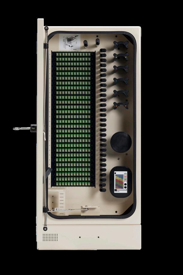
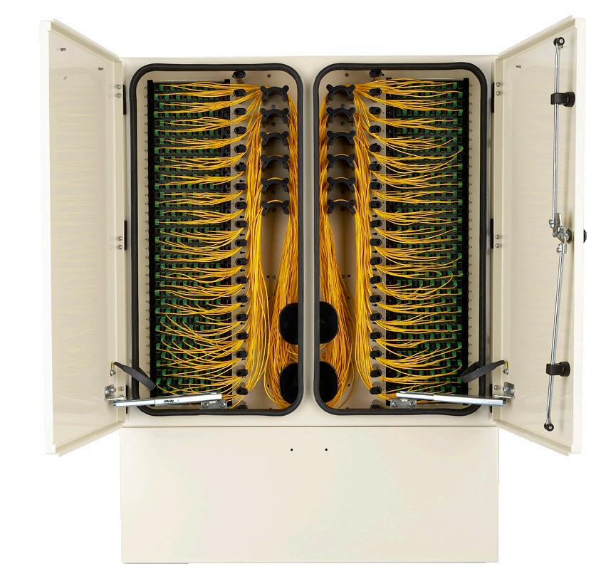
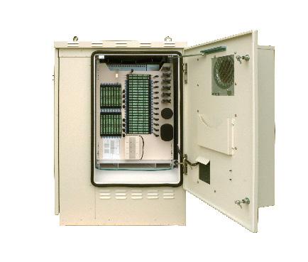
Introduction to Outside Plant Solutions


FieldSmart Cabinets (Passive)
FieldSmart Cabinets (Powered)
FieldSmart®
96-Port PON FDH Cabinet
Application
Clearfield’s FieldSmart PON Fiber Distribution Hub (FDH) Cabinet family provides an interconnect environment from the feeder network through the optical passive splitter to the distribution network. Designed for the outside plant environment, these cabinets provide a single distribution point to deploy FTTH and are ideal for residential, MDUs and business class environments. Providing distribution scalability from 12 to 96 ports, network architecture can be maximized for both existing subscribers as well as future growth opportunities.
Description
The FieldSmart 96-Port PON FDH Cabinet is the smallest PON cabinet in the Clearfield product offering, measuring 24.2” H x 13.5” W x 10.7” D.
Designed for a pole or wall mounted deployment, this cabinet exterior was modeled after our existing FDH cabinet line, while the interior bulkhead was modeled after our pedestal mounted PON insert, offering up to 12 feeder/express ports and up to 96 distribution ports.
The 96-Port PON FDH Cabinet in available in the following options:
• Empty Cabinet
• Patch and Splice Cabinet
• Patch Only Cabinet
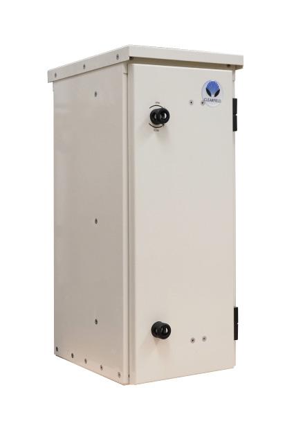
Adding Clearfeld’s Clearview ® Blue Cassettes as needed allows the provider to align capital expenditures with their customer take-rates.
Features and Benefits Integrity
• Terminations are designed, tested and certified to Telcordia GR-326
• Clearfield® FiberDeep® Guarantee: 0.2 dB insertion loss or less, exceeding industry standards
• Fiber cable certified to Telcordia GR-20 and GR-409. Designed, tested and certified to Telcordia GR-3125
• Cabinet constructed with 0.064 aluminum, powder coated for additional protection
• 300 series stainless steel fasteners used on all cabinets Protection
• 12-fiber Clearview Cassette protects fiber from environmental and human factors
• WaveSmart® Ruggedized Splitters are built with ruggedized jacketing and bend-insensitive fiber for all input and output legs
• Pyramid roof and venting provide additional protection in all environments Access
• Clearview Cassette allows for quick visual troubleshooting without opening cassette
• Front and rear access doors
• Bottom exit/entrance for fiber cables
• Compact design allows for quick and secure pole or wall mount installation and deployment Investment
• Fiber is deployed in increments of 12, providing the users the ability to scale from 12 ports to full capacity, aligning capital investment with network layout or subscriber revenue
• Express ports allow for extensions or parallel networks through the cabinet
• Patch and splice configurations eliminate costs associated with additional hand-holes and splice cases
FieldSmart® 96-Port PON FDH Cabinet
Technical Specifications
FieldSmart 96-Port PON FDH Cabinet
Dimensions
24.2” H x 13.5” W x 10.7” D (does not include pole/wall mount brackets)
Empty Cabinet Weight Approx. 30 lbs.
Mounting Options
Pole/Wall Mount – brackets included with each cabinet; No riser available for this cabinet
Feeder/Express Capacity 12 – in a Clearview Blue Cassette
Distribution Capacity Up to 96 in Clearview Blue Cassettes
Cable Entrance Ports 4
Access
Doors on both sides allow complete access to cabinet
Splitters Capacity Up to 5 WaveSmart Ruggedized Splitters
Security 4 Quarter Turn Latches with Pin in Hex Key
Material/Thickness .064” Aluminum with Almond Powder Coat Paint
Pre-Configured Part Numbers
Part Number Description
FMA-H3Z Pole Mount Kit, For FieldSmart and FDH Cabinets - 96, 288, 432. Included with each 96 Port
R-KCZ-000-ZZZ-0000-BSUB FieldSmart 96 Port FDH Cabinet with Pole/Wall Mount Brackets, Capacity-12 Feeder and 96 Distribution Ports, No Cassettes Included
Configured Part Numbers
= No Feeder
3 Select Distribution Port Count
= Port Count in Increments of 12 (Max. 96) 000 = No Distribution
Select Connector
Mode / Type
= Singlemode – non-ribbon 2 = Singlemode – ribbon
Select Jacket Construction B = OSP Riser
= OSP, Non-rated
= Patch and Splice
= OSP Armored
or XXXF Select Ground Box/Extras B = Clearview Blue Cassettes
= Length in meters
= Length in feet
96-Port PON FDH Cabinet
Top, front and side views with dimensions
Side view, with doors closed, showing pole/wall mount brackets
Side view with door open, showing
Bulkhead Cable Management ViewInside the Cabinet
bulkhead orientation
FieldSmart® Fiber Distribution Hub (FDH)
144, 288, 432, 576 and 864-Port PON Cabinet
Application
Clearfield’s FieldSmart Fiber Distribution Hub (FDH) PON Cabinet family provides an interconnect environment from the feeder network through the optical passive splitter to the distribution network. Designed for the outside plant environment, these cabinets provide a single distribution point to deploy FTTH in urban or dense neighborhoods. Providing distribution scalability from 12 to 864 ports, network architecture can be maximized for both existing subscribers as well as future growth opportunities.
Description
The FieldSmart FDH PON Cabinet line is the complete solution for managing 12 to 864 port distribution fibers for an outside plant FTTx PON application. Integrated into the cabinet design is the 12 port Clearview ® Cassette, providing multiple cabinet configurations and allowing the service provider to align the investment in capital equipment to the turn-up of revenue-generating circuits.
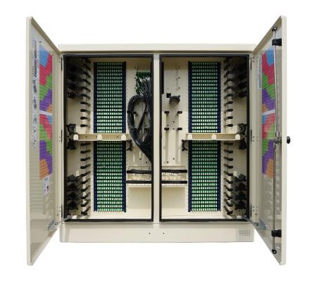
The FieldSmart FDH PON Cabinet family incorporates a new pyramid shaped roof/solar shield and a reusable/replacable venting feature, providing additional protection for deployed fiber. Mounting options include pad, pole or vault mounted with either a 4” or 12” riser. An optional exterior ground box is also available.
Features and Benefits Integrity
• Terminations are designed, tested and certified to Telcordia GR-326
• Clearfield ® FiberDeep ® Guarantee: 0.2 dB insertion loss or less, exceeding industry standards
• Fiber cable certified to Telcordia GR-20 and GR-409. Designed, tested and certified to Telcordia GR-3125
• Constructed with 0.090 aluminum
• Powder coated for additional protection
• 300 series stainless steel fasteners used on all cabinets
• Optional 4” and 12” risers, can be stacked to raise cabinet if required Protection
• 12-fiber Clearview Cassette protects fiber from environmental and human factors
• Rugged cable clamps protect the OSP cable breakouts from twisting and pistoning
• Patch only buffer tubes are fully protected with ruggedized, bend-limiting tubing
• Snake skin sleeving provides additional buffer tube slack storage protection and manageability for patch and splice (Clearfield’s incassette splicing solution) configurations
• WaveSmart Ruggedized Splitters are built with ruggedized jacketing and bend-insensitive fiber for all input and output legs
• Pyramid roof and venting provide additional protection in all environments Access
• Clearview Cassette allows for quick visual troubleshooting without opening cassette
• Front access to pre-terminated assemblies with Clearview removable adapter plate
• Two captive fasteners for quick removal of individual cassettes for trouble shooting, splicing or replacing
• Front and rear access doors
• Bottom exit/entrance for fiber cables Investment
• Fiber is deployed in increments of 12, providing the users the ability to scale from 12 ports to full capacity, aligning capital investment with network layout or subscriber revenue
• Express ports allow for extensions or parallel networks through the cabinet
• Patch and splice configurations eliminate costs associated with additional hand-holes and splice cases
FieldSmart® Fiber Distribution Hub (FDH)
144, 288, 432, 576 and 864-Port PON Cabinet
Technical Specifications
Cassette Types Supported Clearview ® Blue
Connector Types SC/UPC, SC/APC, LC/UPC, LC/APC
Cable Types Indoor/Outdoor, Outdoor, Outdoor Armored, Ribbon and Loose Tube
Door Locks 2 per door
Venting Built-in Replaceable Roof Vent Splice Capacity 12 splices in each Clearview Cassette
Material
Accessories
0.125 (3.175 mm) aluminum with almond powder coating 0.90 (2.286 mm) aluminum with almond powder coating
• Risers: 4” and 12” (101.60 mm or 304.80 mm)
• Exterior Ground Box - Available with 12” Riser Only, Located in Riser
• WaveSmart Ruggedized Splitter
• Mid-Span/Feed-Through Plate Kit
• Pole Mount Kits
• GoreTex Filter Replacement - 020800 GoreTex Filter - 020800
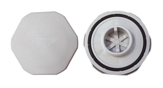
FieldSmart® Fiber Distribution Hub (FDH)
144, 288, 432, 576 and 864-Port PON Cabinet
Configured Part Numbers - 144 Port
Disclaimer/Note: Paper configurator shown is for reference only and should not be used to configure a saleable product configuration. All options shown on paper configurators may not be available or compatible with other options listed. Please contact your Clearfield representative for assistance in product configurations.
1 Select Cabinet Riser/Mounting
A = 4" (101.60 mm)
B = 12" (304.80 mm)
C = No Riser With Pole Mount Kit
D = 4" (101.60 mm) Riser with Pole Mount Kit
2 Select Feeder
1 = 12
2 = 24
Z = No Feeder
3 Select Distribution Port Count
XXX = Port Count in Increments of 12 (Max. 144)
ZZZ = No Distribution
Select Jacket Construction
= OSP Riser
= OSP, Non-rated
= Patch and Splice M = OSP Armored
Select Qty. of 144 Fiber OSP Cables
Ground Box/Extras B = Clearview Blue Cassettes
= Ground Box with 12" Riser; Clearview Blue Cassettes
FieldSmart® Fiber Distribution Hub (FDH)
144, 288, 432, 576 and 864-Port PON Cabinet
Pre-Configured Part Numbers
Vault Options
VC7B-CZP Vault, Clearfield, 36” x 48” x 36”, HDPE, Split Lid, with Cut Out for FieldSmart Cabinets, with Bolt Kit FMA-H3Z-BC-SUB Pole Mount Kit, for FieldSmart FDH cabinets, 144
FieldSmart® Fiber Distribution Hub (FDH)
Configured Part Numbers - 288 Port
Disclaimer/Note: Paper configurator shown is for reference only and should not be used to configure a saleable product configuration. All options shown on paper configurators may not be available or compatible with other options listed. Please contact your Clearfield representative for assistance in product configurations.
2
1
4
FieldSmart® Fiber Distribution Hub (FDH)
PON Cabinet
Configured Part Numbers - 432 Port
Disclaimer/Note: Paper configurator shown is for reference only and should not be used to configure a saleable product configuration. All options shown on paper configurators may not be available or compatible with other options listed. Please contact your Clearfield representative for assistance in product configurations.
FieldSmart® Fiber Distribution Hub (FDH)
144, 288, 432, 576 and 864-Port PON Cabinet
Configured Part Numbers - 576 Port
Disclaimer/Note: Paper configurator shown is for reference only and should not be used to configure a saleable product configuration. All options shown on paper configurators may not be available or compatible with other options listed. Please contact your Clearfield representative for assistance in product configurations.
1 Select Cabinet Riser/Mounting
A = 4" (101.60 mm)
B = 12" (304.80 mm)
2 Select Feeder
1 = 12 6 = 72
2 = 24 7 = 84
3 = 36 8 = 96
4 = 48 Z = No Feeder
5 = 60
3 Select Distribution Port Count
XXX = Port Count in Increments of 12 (Max. 576)
ZZZ = No Distribution
4 Select Connector
A = SC/UPC
C = SC/APC
F = LC/UPC DX
H = LC/APC DX 6 Select Jacket Construction B = OSP Riser E = OSP, Non-rated F = Patch and Splice M = OSP Armored
7 Select Qty.
Select Qty. of 144 Fiber OSP Cables
Select Qty. of 96 Fiber OSP Cables
Select Qty. of 72 Fiber OSP Cables
Select Ground Box/Extras
B = Clearview Blue Cassettes M = Ground Box With 12" Riser Clearview Blue Cassettes
XXXM = Length in meters XXXF = Length in feet XXXM or XXXF
Options 576 Port Cabinet
VC7B-CZP Vault, Clearfield, 36” x 48” x 36”, HDPE, Split Lid, with Cut Out for FieldSmart Cabinets, with Bolt Kit
FieldSmart® Fiber Distribution Hub (FDH)
PON Cabinet
Configured Part Numbers - 864 Port
Disclaimer/Note: Paper configurator shown is for reference only and should not be used to configure a saleable product configuration. All options shown on paper configurators may not be available or compatible with other options listed. Please contact your Clearfield representative for assistance in product configurations.
1 Select Cabinet Riser/Mounting
A = 4" (101.60 mm)
B = 12" (304.80 mm)
2 Select Feeder
1
2 =
3 =
4 =
5 =
3 Select Distribution Port Count
XXX = Port Count in Increments of
(Max. 864)
ZZZ = No Distribution
4 Select Connector
A =
Qty. of 72 Fiber OSP Cables
Select Ground Box/Extras
= Clearview Blue Cassettes M = Ground Box With 12" Riser Clearview Blue Cassettes
FieldSmart® Fiber Distribution Hub (FDH)
144, 288, 432, 576 and 864-Port PON Cabinet
Part Numbers
FieldSmart® Fiber Scalability Center (FSC)
1152-Port PON Cabinet
Application
FieldSmart FSC PON Cabinets provide an interconnect environment from the feeder network through the optical passive splitter to the distribution network in an FTTH PON OSP cabinet. These different cabinet sizes provide scalability from 12 ports to 1,152 ports. Designed for the outside plant environment, these cabinets provide a single distribution point to distribute FTTH in urban or dense neighborhood.
Description
The FieldSmart FSC PON is the complete solution for managing 12 to 1,152 port distribution fibers for an outside plant FTTx PON application. Through the incremental design of the Clearview ® Cassette, user capacity can be scaled from as few as 12 ports to the maximum configuration of the cabinet, allowing the service provider to align the investment in capital equipment to the turn-up of revenue-generating circuits
Features and Benefits
Integrity
• Terminations are designed, tested and certified to Telcordia GR-326
• Clearfield ® FiberDeep ® Guarantee: 0.2 dB insertion loss or less, exceeding industry standards
• Designed, tested and certified to Telcordia GR-3125
• Constructed with 0.125 (3.125 mm) aluminum
• Powder coated for additional protection
• 300 series stainless steel fasteners used on all cabinets
• Optional 4” and 12” risers, can be stacked to raise cabinet if required Protection
• 12-fiber Clearview Cassette protects fiber from environmental and human factors
• Rugged cable clamps protect the OSP cable breakouts from twisting and pistoning
• Patch only buffer tubes are fully protected with ruggedized, bend-limiting tubing
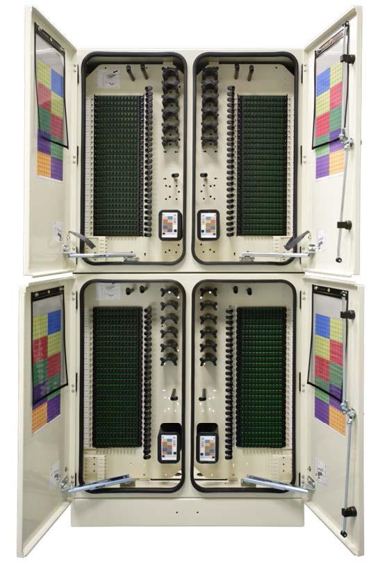
• Snake skin sleeving provides additional buffer tube slack storage protection and manageability for patch and splice (Clearfield’s incassette splicing solution) configurations
• Splitters are built with ruggedized jacketing and bend-insensitive fiber for all input and output legs Access
• Clearview Cassette allows for quick visual troubleshooting without opening cassette
• Front access to pre-terminated assemblies with Clearview removable adapter plate
• Easy two captive fasteners for quick removal of individual cassettes for troubleshooting, splicing or replacing Investment
• Fiber is deployed in increments of 12, providing the users the ability to scale from 12 ports to full capacity, aligning capital investment with network layout or subscriber revenue
• Express ports allow for extensions or parallel networks through the cabinet
• Patch and splice configurations eliminate costs associated with jacketed IFC cabling, hand-holes and splice cases.
Accessories
• Risers: 4” (101.60 mm) and 12” (304.80 mm)
• Exterior Ground Box — Available with 12” Riser Only
• Ruggedized Splitter Bays
• Mid-Span/Feed-Through Plate Kit
• Optional LGX Adapter Bracket Kit (P/N 014380) available to accommodate 6 LGX style modules or 13, ½ wide LGX modules. Max port capacity decrease by 84 (7 cassettes) when used.
FieldSmart® Fiber Scalability Center (FSC)
1152-Port PON Cabinet
Technical Specifications
FieldSmart 1152-Port PON Cabinet
Dimensions (without riser) 64” H x 33” W x 16.9” D (1625.60 mm x 838.20 mm x 429.26 mm)
Weight 172 lbs (78.02 kg)
Port Density 1,152
Feeder/Express Ports 192
Cable Entrances 12
Mounting Options (Hoist kits included with each cabinet) Vault mount; pad mount
Standard Riser Base 4”; 8 lbs (101.60 mm; 3.63 kg)
Optional Riser Base 12”; 20 lbs (304.80 mm; 9.07 kg)
Splitter Slots 36
Cassette Types Supported Clearview ® Blue
Connector Types SC/UPC, SC/APC, LC/UPC, LC/APC
Cable Types Indoor/Outdoor, Outdoor (Riser/Non-Rated), Outdoor Armored (Riser/Non-Rated)
Splice Capacity 12 splices in each Clearview Cassette Material 0.125 (3.175 mm) aluminum with almond powder coating

FieldSmart® Fiber Scalability Center (FSC)
1152-Port PON Cabinet
Configured Part Numbers
1,152-Port Cabinet
• Please contact your Clearfield® representative for more information on ordering this option.
Vault Options
FieldSmart® Fiber Distribution Hub (FDH)
432 and 864-Port Cross-Connect Cabinet
Application
The FieldSmart FDH Cross-Connect Cabinet is the complete solution for managing up to 864 fibers in most any feeder/distribution ratio for an outside plant FTTx application. This solution provides an interconnect environment from the feeder network and the distribution field in a FTTH network.
Description
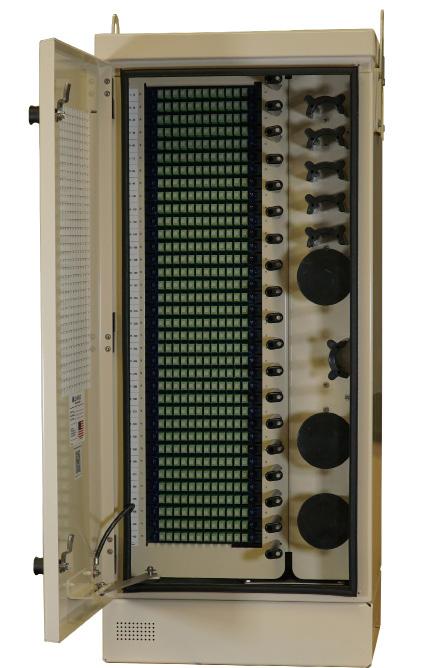
With the Clearview ® Cassette as its foundation, the FieldSmart FDH Cross-Connect Cabinet uses the same components as the FieldSmart Fiber Crossover Distribution System (FxDS) deployed in the central office. This enables service providers to standardize on a single building block, allowing them to stock a single fiber management component for either environment. Technicians also have the ease of working with a single fiber architecture for central office or outside plant deployment - saving training and installation time. Using Clearview, FieldSmart changes the rules of fiber management. Optimal access is ensured to all ports and superior fiber protection is integrated within the Clearview Cassette. Through the incremental design of the Clearview Cassette, user capacity can be scaled from as few as 12 ports to the maximum configuration of the cabinet, allowing the service provider to align the investment in capital equipment to the turn-up of revenuegenerating circuits. Further, labor and other field costs are minimized through this craft-friendly layout.
The FieldSmart FDH Cross Connect Cabinet family incorporates a new pyramid shaped roof/solar shield and a reusable/replaceable venting feature, providing additional protection for deployed fiber. Mounting options include pad, pole or vault mounted with either a 4” or 12” riser. An optional exterior ground box is also available.
Features and Benefits
Integrity
• Terminations designed, tested and certified to Telcordia GR-326
• Clearfield ® FiberDeep ® Guarantee: 0.2 dB insertion loss or less, exceeding industry standards
• Designed to comply to Telcordia GR-20, GR-409, GR-487 and GR-3125
• Constructed with 0.090 (3.175 mm) aluminum
• Powder coated for additional protection
• 300 series stainless steel fasteners used on all cabinets
• Optional 4” and 12” risers, can be stacked to raise cabinet if required Protection
• 12-fiber Clearview Cassette protects fiber from environmental and human factors
• Rugged cable clamps protect the OSP cable breakouts from twisting and pistoning
• Patch only buffer tubes are fully protected with ruggedized, bend-limiting tubing
• Snake skin sleeving provides additional buffer tube slack storage protection and manageability for patch and splice (Clearfield’s incassette splicing solution) configurations
• Pyramid roof and venting provide additional protection in all environments Access
• Clearview Cassette allows for quick visual troubleshooting without opening cassette
• Front access to pre-terminated assemblies with Clearview removable adapter plate
• Two captive fasteners for quick removal of individual cassettes for trouble shooting, splicing or replacing
• Front and rear access doors
• Bottom exit/entrance for fiber cables Investment
• Fiber is deployed in increments of 12, providing the users the ability to scale from 12 ports to full capacity, aligning capital investment with network layout or subscriber revenue
• Express ports allow for extensions or parallel networks through the cabinet
• Patch and splice configurations eliminate costs associated with additional hand-holes and splice cases
FieldSmart® Fiber Distribution Hub (FDH) 432
and 864-Port Cross-Connect Cabinet
Technical Specifications
Max. Feeder/Express Ports TBD by Customer - based on network design
Cables Entrances 6
Mounting Options (Hoist kits included with each cabinet)
Cassette Types Supported Clearview ® Blue
Connector Types
Cable Types
SC/UPC, SC/APC, LC/UPC, LC/APC
Indoor/Outdoor, Outdoor, Outdoor Armored, Ribbon and Loose Tube
Door Locks 2 per door
Venting
Built-in Replaceable Roof Vent Splice Capacity 12 Splices in Each Clearview Cassette
Recommended Jumper Length 2 meters
Material 0.900 (2.286 mm) aluminum with almond powder coating
Accessories
• Risers: 4” and 12” (101.60 mm or 304.80 mm)
• Exterior Ground Box - Available with 12” Riser Only, Located in Riser
• Mid-Span/Feed-Through Plate Kit
• Pole Mount Kits
• GoreTex Filter Replacement - 020800

GoreTex Filter - 020800
FieldSmart® Fiber Distribution Hub (FDH) 432
and 864-Port Cross-Connect Cabinet
Configured Part Numbers - 432 Port
Disclaimer/Note: Paper configurator shown is for reference only and should not be used to configure a saleable product configuration. All options shown on paper configurators may not be available or compatible with other options listed. Please contact your Clearfield representative for assistance in product configurations.
A
C
Mode / Type 1 Select Cabinet Housing Size
1 = Singlemode – Non-Ribbon
2 = Singlemode – Ribbon
1
0 = 0 B = 2-72
1 = 1-96 C = 3-72
2 = 2-96 D = 4-72
3 = 3-96 E = 5-72
4 = 4-96 F = 6-72 A = 1-72
Select Ground Box/Extras B = Clearview Blue Cassettes M = Ground Box with 12" Riser Clearview Blue Cassettes
1 = Clearview Blue with 1 set of 014380
2 = Clearview Blue with 2 sets of 014380
3 = Clearview Blue with ground box and 1 set of 014380
4 = Clearview Blue with ground box and 2 sets of 014380
5 = Clearview Blue with 1 set of 020060 6 = Clearview Blue with 2 sets of 020060
7 = Clearview Blue with ground box and 1 set of 020060
8 = Clearview Blue with ground box and 2 sets of 020060
Select Length
FieldSmart® Fiber Distribution Hub (FDH)
and
Cabinet
FieldSmart® Fiber Distribution Hub (FDH) 432 and 864-Port Cross-Connect Cabinet
Configured Part Numbers - 864 Port
Disclaimer/Note: Paper configurator shown is for reference only and should not be used to configure a saleable product configuration. All options shown on paper configurators may not be available or compatible with other options listed. Please contact your Clearfield representative for assistance in product configurations.
B
0 = 0 C = 3-216
1 = 1-288 D = 4-216
2 = 2-288 E = 1-288; 1-216
3 = 3-288 F = 1-288; 2-216 A = 1-216 G = 2-288; 1-216 B = 2-216
0 = 0 4 = 4 1 = 1 5 = 5 2 = 2 6 = 6 3 = 3
0 = 0 8 = 8-96 F = 6-72
1 = 1-96 9 = 9-96 G = 7-72
2 = 2-96 A = 1-72 H = 8-72
3 = 3-96 B = 2-72 J = 9-72
4 = 4-96 C = 3-72 K = 10-72
5 = 5-96 D = 4-72 M = 11-72
6 = 6-96 E = 5-72 N = 12-72
7 = 7-96
10 Select Distribution Count
XXX = port count in increments of 12
11 Select Qty. of 288/216 Fiber OSP Cables
0 = 0 C = 3-216
1 = 1-288 D = 4-216
2 = 2-288 E = 1-288; 1-216
3 = 3-288 F = 1-288; 2-216 A = 1-216 G = 2-288; 1-216 B = 2-216
0 = 0 4 = 4
1 = 1 5 = 5
2 = 2 6 = 6
3 = 3
0 = 0 8 = 8-96 F = 6-72
1 = 1-96 9 = 9-96 G = 7-72
2 = 2-96 A = 1-72 H = 8-72
3 = 3-96 B = 2-72 J = 9-72
4 = 4-96 C = 3-72 K = 10-72
5 = 5-96 D = 4-72 M = 11-72
6 = 6-96 E = 5-72 N = 12-72 7 = 7-96
FieldSmart® Fiber Distribution Hub (FDH) 432
and 864-Port Cross-Connect Cabinet
Vault Options
864 Port Cabinet Part Number
VC7B-CZP
V9B-HZP-PC
LGX Bracket Options
Vault, Below Grade Clearfield, Split HDPE Lid, with Cut Out for FieldSmart Cabinets, Flared Wall, with Bolt Kit
Vault, Quazite 48 x 48 x 36” (1219.20 mm x 1219.20 mm x 914.40 mm), complete split polymer concrete lid, cut out for 864 cabinets, fiberglass straight wall, requires 020538 Bolt Kit - ordered separately
014380 Kit, LGX Bracket Install, FSC and FHD Cabinets Uses 014376 Bracket 020060 Kit, LGX Bracket Install, FSC and FDH Cabinets, Works for 1/2 Wide Modules Uses 019901 Bracket
Part Number 014380
Part Number 020060
864-Port Cabinet with LGX Brackets Installed
FieldSmart® Fiber Scalability Center (FSC)
1728-Port Cross-Connect Cabinet
Application
The FieldSmart 1728-Port Cross-Connect Cabinet is the complete solution for managing up to 1,728 fibers in most any feeder/distribution ratio for an outside plant FTTx application. This solution provides an interconnect environment from the feeder network and the distribution field in a FTTH network.
Description
With the Clearview ® Cassette as its foundation, the FieldSmart 1728-Port Cross-Connect Cabinet uses the same components as the FieldSmart Fiber Crossover Distribution System (FxDS) deployed in the central office. This enables service providers to standardize on a single building block, allowing them to stock a single fiber management component for either environment. Technicians also have the ease of working with a single fiber architecture for central office or outside plant deployment - saving training and installation time. Using Clearview, the FieldSmart changes the rules of fiber management.
Optimal access is ensured to all ports and superior fiber protection is integrated within the Clearview Cassette. Through the incremental design of the Clearview Cassette, user capacity can be scaled from as few as 12 ports to the maximum configuration of the cabinet, allowing the service provider to align the investment in capital equipment to the turn-up of revenuegenerating circuits. Further, labor and other field costs are minimized through this craft-friendly layout.
Features and Benefits
Integrity
• Terminations are designed, tested and certified to Telcordia GR-326
• Clearfield ® FiberDeep ® Guarantee: 0.2 dB insertion loss or less, exceeding industry standards
• Designed, tested and certified to Telcordia GR-3125
• Constructed with 0.125 (3.125 mm) aluminum
• Powder coated for additional protection
• 300 series stainless steel fasteners used on all cabinets
• Optional 4” and 12” risers, can be stacked to raise cabinet if required Protection
• 12-fiber Clearview Cassette protects fiber from environmental and human factors
• Rugged cable clamps protect the OSP cable breakouts from twisting and pistoning
• Patch only buffer tubes are fully protected with ruggedized, bend-limiting tubing
• Snake skin sleeving provides additional buffer tube slack storage protection and manageability for patch and splice (Clearfield’s incassette splicing solution) configurations
• Splitters are built with ruggedized jacketing and bend-insensitive fiber for all input and output legs Access
• Clearview Cassette allows for quick visual troubleshooting without opening cassette
• Front access to pre-terminated assemblies with Clearview removable adapter plate
• Two captive fasteners for quick removal of individual cassettes for trouble shooting, splicing or replacing
• Front and rear access doors
• Bottom exit/entrance for fiber cables Investment
• Fiber is deployed in increments of 12, providing the users the ability to scale from 12 ports to full capacity, aligning capital investment with network layout or subscriber revenue
• Express ports allow for extensions or parallel networks through the cabinet
• Patch and splice configurations eliminate costs associated with jacketed IFC cabling, hand-holes and splice cases.
FieldSmart® Fiber Scalability Center (FSC)
1728-Port Cross-Connect Cabinet
Technical Specifications
FieldSmart 1152-Port PON Cabinet
Dimensions (without riser) 64” H x 33” W x 16.9” D (1625.60 mm x 838.20 mm x 429.26 mm)
Weight 192 lbs
Port Density 1,728
Feeder/Express Ports 192
Cable Entrances 12
Mounting Options (Hoist kits included with each cabinet) Vault mount; pad mount
Standard Riser Base 4”; 8 lbs (101.60 mm; 3.63 kg)
Optional Riser Base 12”; 20 lbs (304.80 mm; 9.07 kg)
Splitter Slots 36
Cassette Types Supported Clearview ® Blue
Connector Types SC/UPC, SC/APC, LC/UPC, LC/APC
Cable Types Indoor/Outdoor, Outdoor (Riser/Non-Rated), Outdoor Armored (Riser/Non-Rated)
Splice Capacity 12 splices in each Clearview Cassette Material 0.125 (3.175 mm) aluminum with almond powder coating
Accessories
• Risers: 4” and 12” (101.60 mm or 304.80 mm)
• Exterior Ground Box - Available with 12” Riser Only.
• Mid-Span/Feed-Through Plate Kit
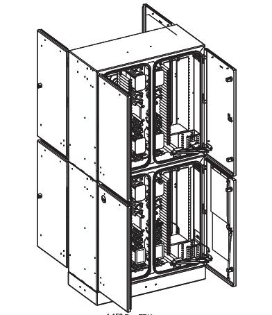
FieldSmart® Fiber Scalability Center (FSC)
1728-Port Cross-Connect Cabinet
Configured Part Numbers
1,728-Port Cabinet
• Please contact your Clearfield® representative for more information on ordering this option.
Vault Options
FieldSmart ® Fiber Distribution Hub (FDH)
Pole Mount Kit
Description
The FieldSmart Fiber Distribution Hub (FDH) and Fiber Scalability Center (FSC) Pole Mount Kit provides the ability to pole mount the 96-port, 144-port, 288-port and 432-port PON, 432 port cross-connect cabinets. Also available are the Pole Mount Under Plate Kits. It has an easy to install hook and tab design with a rugged thru-pole lag bolt for security.
Pre-Configured Part Numbers
Part Number
FMA-H3Z-BC-SUB Pole mount kit only, for 144 FDH
FMA-H3Z-KIT-SUB Kit, includes Pole Mount Kit and under plate kit
FMA-H3Z-KIT-SUB-144 Kit, includes Pole Mount Kit and under plate kit

FDH PON
PON, 432 cross-connect
FDH PON
FMA-H3Z-KIT-432-SUB Kit, includes Pole Mount Kit and under plate kit 432 PON only
FMA-H3Z-PLT-STRG-SUB Pole Mount Under Plate Kit, with security clamp 288 PON, 432 cross-connect
FMA-H3Z-PLT-SUB Pole Mount Under Plate Kit 144 & 288 PON, 432 cross-connect
FMA-H3Z-SUB Pole Mount Kit 288 PON, 432 PON, 432 cross-connect, 96-port PON Pole Mount Cabinet
PON Pole Mount Under Plate Kit
PON Only FMA-H3Z-SUB FSC Pole Mount Kit (288 and 432 PON, 432 Cross-Connect and HCC only)
Cabinet Entrance Expansion Kit
Description
The FieldSmart Cable Expansion Kit includes all the material to add up to 3 additional cables to any of our FieldSmart Cabinets. It includes sealcons, nuts, o-rings, grommets and strength member tie off clamps.
Pre-Configured Part Numbers
Part Number Description
FMA-H3Z-PLT-SUB FSC Box Pole Mount Underplate Kit (288 and 432 PON, 432 Cross-Connect and HCC only)

FMA-XXX-14 Cabinet Entrance Expansion Kit, contains extra sealcon and grommets
FieldSmart ® Fiber Distribution Hub (FDH)
Accessories
Deep Socket Wrenches
Description
The handy, light weight Deep Socket Wrench is manufactured from alloy steel. In a patch and splice (Clearfield’s in-cassette splicing solution) cabinet where the customer installs the incoming cable, the cable must go through the watertight fittings that are provided with each cabinet. Watertight fittings must then be installed into the FieldSmart Cabinet. These wrenches are designed to make tightening of the dome, thread and lock nuts more manageable. The wrench encloses the dome nut on five sides, giving the nut additional rigidity during tightening. This is especially important if a stiff cable is used.

Note: Does not work with all Flex Fittings. One of each style wrench (40 mm and 42 mm) is needed to tighten the 1” watertight fitting used on all FieldSmart Cabinets.
Torque Recommendations for Strain Relief Fittings
Torque in Inch Pounds - in lb. (Newton Meters - Nm)
Pre-Configured Part Numbers
Mid-Span Opening Feed-Through Plate Kit
Description
The Mid-Span Opening Feed-Through Plate Kit is specifically designed for Clearfield ® FieldSmart Fiber Distribution Hubs (FDH) and Fiber Scalability Center (FSC) products. It provides the hardware components to confidently secure the ring cut/mid-span fiber optic cable in an OSP cabinet. This kit utilizes the existing cable entry/exit ports in the Clearfield OSP cabinets. It saves the customer time and money by allowing them to only splice the required fiber counts needed into the cabinet.
Pre-Configured Part Numbers
009692
027164
FieldSmart FSC Mid-Span Opening Feed-Through Plate Kit for cables up to 1” (25.4 mm) O.D.; includes strength member tie off clamp
FieldSmart FDH Mid-Span Opening Feed-Through Plate Kit for cables up to 1.25” (31.75 mm) O.D.; includes strength member tie off clamp
016757 Strength member tie off kit - for retro fit or older version of 009692
016741
009692
FieldSmart ® Fiber Distribution Hub (FDH)
Cassette - Cabinet Adapter Brackets
Description
Vertical bracket kit for FieldSmart Hub Collapse Cabinets. These brackets mount vertically in one of the 4 LGX slots and will allow the customer to add up to 5 additional cassettes per slot. We are including one set of these brackets with every HCC that is sold – as part of the standard product offering. If the customer needs additional brackets, please have them order additional kits.
Pre-Configured Part Numbers
Part
- Cabinet Adapter Brackets
LGX - Cabinet Adapter Brackets
Description
Horizontal bracket kit for FieldSmart 144 PON, 288 PON, 432 PON, 576 PON, 864 PON, 1152 PON, 432 Cross-Connect, 864 Cross-Connect and 1728 Cross-Connect. These brackets mount horizontally within the cabinet and will allow the customer to mount up to 6 LGX style modules and 13 ½ wide LGX modules inside of the cabinet. The brackets will reduce the capacity of terminations within the cabinet by 84 ports (7 cassettes). These kits will be available as an optional item and should be ordered separately by the customers.
Pre-Configured Part Numbers
014380
- Cabinet Adapter Brackets
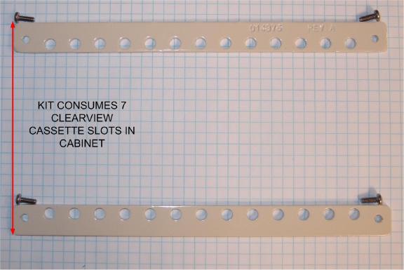
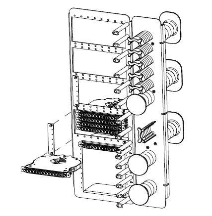
FieldSmart ® Fiber Distribution Hub (FDH)
Accessories
Cable Protection Boot
Description
The FieldSmart Cable Protection Boot is a dark gray, vacuum-formed plastic, one piece boot that is attached to the pole and designed to provide additional cable protection where the cables enter/exit the pole mount cabinet. Designed to work in conjunction with a standard 2” U-Channell, it provides additional security and encases all incoming cables and conduit. Designed to fit any Clearfield pole mount FDH Cabinet, the FieldSmart Cable Protection Boot provides additional security and aesthetic appeal by encasing the incoming and outgoing fiber or conduit between the cabinet and the pole.
Pre-Configured Part Numbers
Pole Mount Protection Boot
Riser Kits
Description
Specifically designed for FieldSmart Cabinets, these kits can be installed onto existing risers (included with each cabinet). Risers are available in 4” or 12”. All 12” Riser Kits include an access panel, allowing for easy access to cable entrance area underneath the cabinet.
These riser kits can be stacked, allowing the cabinet to be raised to the required height depending on the individual application requirements. Each kit includes the riser and mounting bolt kit.
Pre-Configured Part Numbers
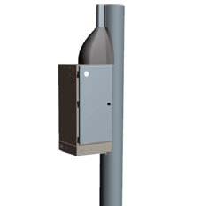
StreetSmart® Pre-Assigned FDH Cabinet
288-Port PON Cabinet with Pre-Installed Splitters
Application
Clearfield’s StreetSmart ® Pre-Assigned FDH PON Cabinet provides an interconnect environment from the feeder network through the passive optical splitter to the distribution network.
Designed for rapid PON Network deployments, these cabinets provide a single distribution point, making it the ideal solution for deploying FTTH (fiber-to-the-home) where high potential take rates are expected. Pre-Assigned WaveSmart High Density 1 x 32 Splitters are loaded into the cabinet with a pre-terminated fiber tail, making installation and deployment very cost and time effective.
Description
The StreetSmart Pre-Assigned FDH PON Cabinet provides a turn-key solution for up to 288 distribution fibers for an outside plant FTTx PON application. WaveSmart High Density 1 x 32 Splitters are installed and pre-assigned into Clearfield’s 12 pack SC/APC module adapters, allowing the service provider to instantly turn-up revenue-generating circuits.
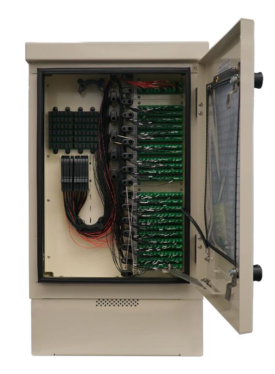
The StreetSmart 288 PON Cabinet incorporates a cross-cut roof designed to shed water and includes a roof/solar shield and a reusable/replaceable venting feature, providing additional protection for deployed fiber. The outer shell of the cabinet is replaceable, allowing the cabinet to be repaired if damaged. Mounting options include pad, pole or vault mounted with either a 6” or 12” riser.
Features and Benefits
Integrity
• Terminations designed, tested and certified to Telcordia GR-326
• Clearfield® FiberDeep® Guarantee: 0.2 dB insertion loss or less, exceeding industry standards
• Fiber cable certified to Telcordia GR-20 and GR-409
• Cabinets are designed, tested and certified to GR-3125
• Constructed with 0.090 aluminum
• Powder coated for additional protection
• 300 series stainless steel fasteners used on all cabinets
• Optional 6” and 12” risers
Protection
• 12 pack fiber modules protects fiber from environmental and human factors
• Rugged cable clamps protect the OSP cable breakouts from twisting and pistoning
• Patch only buffer tubes are fully protected with ruggedized, bend-limiting tubing
• WaveSmart High Density Splitters are built with ruggedized jacketing and bend-insensitive 900 um fiber for all input and output legs
• Cross-cut roof and venting provide additional protection in all environments
Access
• 12 pack fiber modules snap into bulkhead from the front allowing for quick visual troubleshooting without opening
• Front and side access doors
• Bottom exit/entrance for fiber cables
Investment
• Feeder and Distribution Fiber are pre-terminated into cabinet - No additional splicing required
• WaveSmart High Density Splitters are loaded and pre-assigned into cabinet
• Deployment time is minimized, allowing revenue generating circuits to be turned up immediately
StreetSmart® Pre-Assigned FDH Cabinet 288-Port PON Cabinet with
Pre-Installed Splitters
Technical Specifications
288-Port PON Cabinet with Pre-Installed Splitters
Dimensions
Weight
22.72” T x 15.47” W x 14.18” D (577.08mm T x 393.94mm W x 360.17mm D) * Without Riser
40 lbs. (18.14 kg)
Dist. Port Density 144 or 288
Max. Feeder/Express Ports 12 or 24
Cable Entrances 4
Mounting Options (Hoist kits included with each cabinet)
Riser Base
Vault mount; pole mount; pad mount
6”; 8 lbs (127 mm; 2.72 kg) 12”; 12 lbs. (304.80 mm; 5.44 kg)
Access door in rear of riser base on both the 6” and 12” risers
Pre-loaded WaveSmart High Density Splitters with 900um Legs 4 or 8
Splitter Staging Capacity 72
Connector Modules 12 Pack Adapter Modules
Connector Types SC/UPC, SC/APC
Cable Types Indoor/Outdoor, Outdoor, Outdoor Armored, Ribbon and Loose Tube
Door Locks 2 per door
Venting Built-in Replaceable Roof Vent
Material
Accessories
0.90 (2.286 mm) Aluminum with almond powder coating
• Risers: 6” and 12” (127 mm or 304.80 mm)
• WaveSmart High Density Splitter
• Pole Mount Kits
• Gore-Tex Filter Replacement
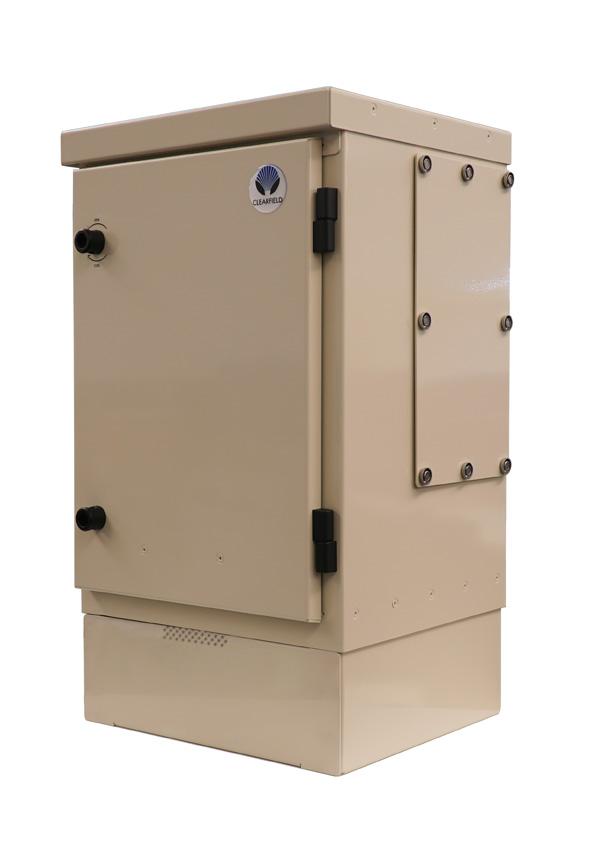
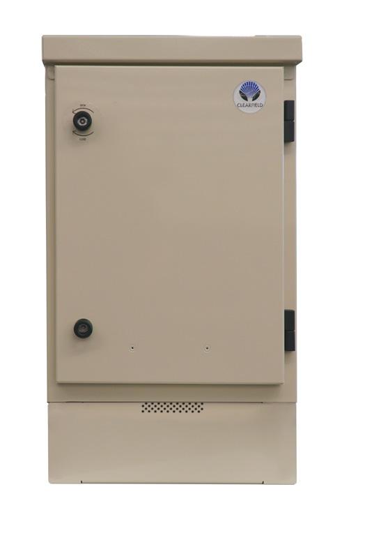

288-Port PON Cabinet with Pre-Installed Splitters
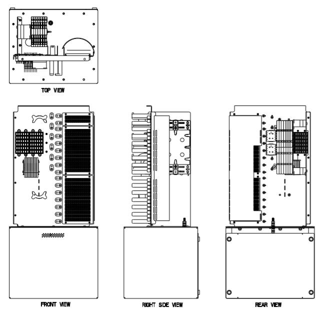
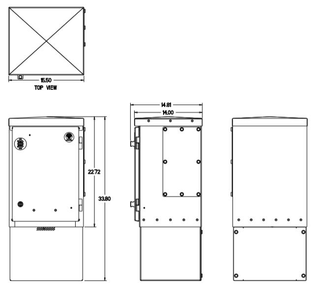
StreetSmart® Pre-Assigned FDH Cabinet
288-Port PON Cabinet with Pre-Installed Splitters
Configured Part Numbers
Disclaimer/Note: Paper configurator shown is for reference only and should not be used to configure a saleable product configuration. All options shown on paper configurators may not be available or compatible with other options listed. Please contact your Clearfield representative for assistance in product configurations.
2 Select
1
2
1
= Length in Feet
= Length in Meters
Part Number Description
V6A-CZP
V6B-CZP
V7A-CZP
V7B-CZP
Vault, below grade Pencell, 24” W x 36” L x 24” D (609.60 mm x 914.40 mm x 609.60 mm), split HDPE lid, hex bolts, green, with cut out for FieldSmart Cabinets, straight wall, with bolt kit
Vault, below grade Pencell, 24” W x 36” L x 36” D (609.60 mm x 914.40 mm x 914.40 mm), split HDPE lid, hex bolts, green, with cut out for FieldSmart Cabinets, straight wall, with bolt kit
Vault, below grade Pencell, 30” W x 48” L x 24” D (762.00 mm x 1219.20 mm x 609.60 mm), split HDPE lid, hex bolts, green, with cut out for FieldSmart Cabinets, straight wall, with bolt kit
Vault, below grade Pencell, 30” W x 48” L x 36” D (762.00 mm x 1219.20 mm x 914.40 mm), split HDPE lid, hex bolts, green, with cut out for FieldSmart Cabinets, straight wall, with bolt kit
FMA-H3Z-BC-SUB Pole Mount Kit, for FieldSmart FDH cabinets, 144
FieldSmart ® Fiber Active Cabinet (FAC) 400
Application
The FieldSmart Fiber Active Cabinet (FAC) 400 broadband enclosure has been designed with the philosophy of modularity and flexibility, while maintaining a maximum heat dissipation capability. The cabinet’s small form factor design allows for speedy delivery of subscriber services in an assortment of deployment scenarios. Compliant with GR-487, the FAC 400 is the ideal outdoor cabinet solution for the harshest outdoor conditions, providing a sealed internal environment where external air and humidity are completely isolated from the electronic equipment.
Description
The FAC 400 is an environmentally-controlled enclosure constructed of powder-coated aluminum. The FAC 400’s equipment bay features a 19” vertical equipment rack, accommodating up to 4RU of active electronics equipment. The FAC 400 provides up to 192 internal fiber distribution ports for subscriber PON deployments, along with complementary splitter capacity. The FAC 400 accepts local AC power and uses a door mounted integrated air-to-air heat exchanger and DC-powered fans to cool the equipment inside the cabinet. A separate, vented, under-cabinet compartment houses optional batteries.
Features and Benefits
Integrity
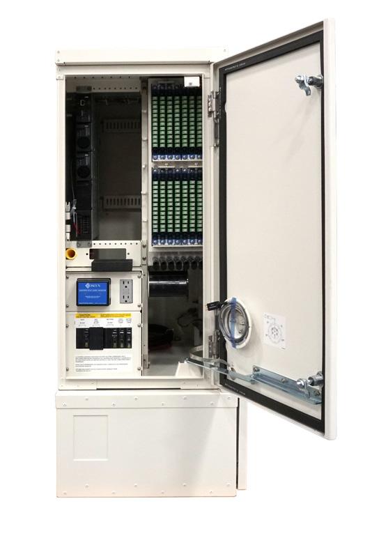
• Designed to seamlessly integrate a variety of standard options that are expected in remote cabinets, such as the rectifier system, battery base, battery warmers and field configurable fiber or copper distribution frames
• Supports a variety of cabinet mounting options including pad, pole, wall and H-frame eliminating concern with right-of-way issues and problematic installation locations
Protection
• Telcordia GR-487 compliant and UL-60950/UL-50 spec
• Environmentally sealed design protects internal equipment investment from dust and rain
• Rated for deployments in harsh environments per GR-487: -40°F to +115°F (-40°C to +46°C)
Access
• Provides front and side doors for full access to the equipment
• Designed to allow access to all complementary elements of a remote outdoor cabinet deployment such as the copper or fiber cables, fiber splicing and distribution modules, power and DC distribution systems, AC power and battery charge breakers, AC outlet, etc, in a compact form factor
• Door security and hardware features designed to protect from vandalism and theft
Investment
• Cabinet engineered features designed to ensure ease of maintenance and eliminate service interruptions
• Provides an ideal platform for the migration of copper access services to fiber access infrastructure and electronics
FieldSmart ® Fiber Active Cabinet (FAC) 400
Technical Specifications
FieldSmart FAC 400
Dimensions
Weight
Mounting Options
AC Power Center Options
AC/DC Rectifier Option
Cooling/Environmental
Wired Capacity
Fiber Management Options
Copper Protection Options
48”H (with battery base) x 24”W x 29”D
Local AC power w/ single 60 Ah battery base: 156 lbs. Equipped with one 60 Ah battery string: 340 lbs.
Local AC power w/ dual 60 Ah battery base: 184 lbs. Equipped with two 60 Ah battery strings: 525 lbs.
Pour-in-Place Template, Pole Mount, Wall Mount, Vault/Riser and Pre-Cast Pad (3rd party supplied)
Optional integrated AC load center, 110–240 VAC single phase, 30 Amp service with UL listed service disconnect, high power Joslyn AC surge protector
Alpha Cordex 1RU -48 VDC Rectifier System Two 25 Amp rectifier modules, auto-senses and adjusts for low and high AC input. CXCM1+ Controller
Low input (100–185 VAC): Max. total power output 1200 Watts; Max. total current 25 Amps (2 modules, non-redundant)
High input (185–264 VAC): Max. total power output 2400 Watts; Max. total current 50 Amps (2 modules, non-redundant)
700 Watt cooling capacity with Dantherm door mount heat exchanger
Ambient temperature per GR-487: –40° F to +115° F (-40°C to +46°C)
Fiber: Up to 192 subscriber fiber drops (SC connectors); (6) 1x32 PON splitters
Copper: Up to 288 copper lines with MS2 or 710 splice options
12-position fiber splice tray (default), up to 192-position fiber distribution in 48- or 96-port increment assemblies; SC connector fiber spool and routing facilities. Integrated 1:16 or 1:32 GPON Splitters (option) LGX based 6-position cassette for fiber splicing or termination.
Standard 5-pin protection blocks — modular in 48-pair increments. Up to six 48-pair protection blocks Available Rack Units 4
UL-60950, Standard for Safety, Issue 1, April 1, 2003 CAN/CSA-C22.2 No. 60950 EMC FCC Part 15
Class A ICES-003 Class A
Safety and Compliance
Telcordia, GR-63-CORE, NEBS Telcordia, GR-487, Generic Requirements for Electronic Equipment Cabinets
Pre-Configured Part Numbers
Part Number
R-1ZDA-ZZZZ-ZZZ-ZZZZZ
Description
FieldSmart Fiber Active Cabinet, FAC 400 Enclosure, Vertical 19 Inch Equipment Rack, 300W Heat Exchanger, No Load Center, No Rectifier, No Battery String, No Bulkhead
FieldSmart ® Fiber Active Cabinet (FAC) 400
Configured Part Numbers
Disclaimer/Note: Paper configurator shown is for reference only and should not be used to configure a saleable product configuration. All options shown on paper configurators may not be available or compatible with other options listed. Please contact your Clearfield representative for assistance in product configurations.
Mounting Options
Battery Options
FieldSmart ®
Fiber Active Cabinet (FAC) 900
Application
The FieldSmart Fiber Active Cabinet (FAC) 900 has been designed to offer a low profile and compact size. It complies with a 36” height requirement that allows a minimum intrusive effect in urban, suburban and residential areas. Compliant with GR-487, the FAC 900 is the ideal outdoor cabinet solution for the harshest outdoor conditions, providing a sealed internal environment where external air and humidity are completely isolated from the electronic equipment.
Description
The FAC 900 is an environmentally-controlled enclosure constructed of powder-coated aluminum. The FAC 900 cabinet’s equipment compartment features a 19” swing frame front and rear, accommodating up to, 9RU of active electronics equipment. The FAC 900 provides up to 576 internal fiber distribution ports for subscriber PON deployments, along with complementary splitter capacity. The FAC 900 accepts local AC power and uses a door mounted integrated air-to-air heat exchanger and DC-powered fans to cool the equipment inside the cabinet. A separate, vented, internal compartment houses an optional battery string. In addition, an optional under-cabinet battery compartment can be ordered.
Features and Benefits
Integrity

• Designed to seamlessly integrate a variety of standard options that are expected in remote cabinets, such as the rectifier system, battery base, battery warmers and field configurable fiber or copper distribution frames
• Supports a variety of cabinet mounting options including pad, pole, wall and H-frame eliminating concern with right-of-way issues and problematic installation locations
Protection
• Telcordia GR-487 compliant and UL-60950/UL-50 spec
• Environmentally sealed design protects internal equipment investment from dust and rain
• Rated for deployments in harsh environments per GR-487: -40°F to +115°F (-40°C to +46°C)
Access
• Provides front and side doors for full access to the equipment
• Designed to allow access to all complementary elements of a remote outdoor cabinet deployment such as the copper or fiber cables, fiber splicing and distribution modules, power and DC distribution systems, AC power and battery charge breakers, AC outlet, etc.
• Door security and hardware features designed to protect from vandalism and theft
Investment
• The FAC 900 is designed for modular expansion, allowing cost effective service deployment and scalability
• Cabinet engineered features designed to ensure ease of maintenance and eliminate service interruptions
• Provides an ideal platform for the migration of copper access services to fiber access infrastructure and electronics
FieldSmart ® Fiber Active Cabinet (FAC) 900
Technical Specifications
FieldSmart FAC 900
Dimensions
Weight
Mounting Options
AC Power Center Options
Base cabinet: 36”H x 25”W x 57”D (battery box internal to cabinet)
Riser options for cabinet: 6”, 12” or 16” H
AC/DC Rectifier Option
Cooling/Environmental
Wired Capacity
Fiber Management Options
Local AC power w/ 100 Ah battery enclosure: 290 lbs. Equipped with one 100 Ah battery string: 575 lbs.
Pre-Cast or Pour-in-Place Pad Template, Wall/H-Frame Mount, Vault/Riser (3rd Party Supplied)
AC Power feed: 240 VAC single phase, 50/60HZ, 30 Amp service with UL listed service disconnect, high power Joslyn AC surge protector
Alpha Cordex 1RU -48 VDC Rectifier System Two 25 Amp rectifier modules, auto-senses and adjusts for low and high AC input. CXCM1+ Controller
Low input (100–185 VAC): Max. total power output 1200 Watts; Max. total current 25 Amps (2 modules, non-redundant)
High input (185–264 VAC): Max. total power output 2400 Watts; Max. total current 50 Amps (2 modules, non-redundant)
1050 Watt cooling capacity with Dantherm door mount heat exchanger, as per GR-487 Generic Requirement
Ambient temperature (per GR-487): -40°F to +115°F (-40°C to +46°C)
Fiber: Up to 576 subscriber fiber terminations with internal battery box in cabinet, up to 576 subscriber fiber terminations (with or without internal battery box in cabinet). Up to 18 integrated PON splitters.
Copper: Up to 384 copper lines with MS2 or 710 splice options
12-or 24-position Clearfield Fiber Splice and distribution on 19/23” mount. Support for in-cabinet GPON and ActiveE fiber management: Up to 576 position fiber distribution in 12-, 24-, 48-, or 96-port increment assemblies; SC/APC connector, loose tube or ribbon. Up to eighteen integrated 1x2, 1x16, 1x32 GPON Splitters (optional).
Copper Protection Options Standard 5-pin protection blocks — modular in 48-pair increments, up to eight 48-pair protection blocks
Available Rack Units Up to 9RU in a 19” rack
UL-60950, Standard for Safety, Issue 1, April 1, 2003 CAN/CSA-C22.2 No. 60950 EMC FCC Part 15 Class A ICES-003 Class A
Safety and Compliance
Telcordia, GR-63-CORE, NEBS Telcordia, GR-487, Generic Requirements for Electronic Equipment Cabinets
Pre-Configured Part Numbers
FieldSmart ® Fiber Active Cabinet (FAC) 900
Configured Part Numbers
Disclaimer/Note: Paper configurator shown is for reference only and should not be used to configure a saleable product configuration. All options shown on paper configurators may not be available or compatible with other options listed. Please contact your Clearfield representative for assistance in product configurations.
Mounting Options
FieldSmart ® Fiber Active Cabinet (FAC) 3200
Application
The FieldSmart Fiber Active Cabinet (FAC) 3200 has been designed with the philosophy of modularity and flexibility, while maintaining a maximum cooling capability for the active electronics investment. Compliant with GR-487, the FAC 3200 is the ideal outdoor cabinet solution for the harshest outdoor conditions, providing a sealed internal environment where external air and humidity are completely isolated from the electronic equipment.
Description
The FAC 3200 outdoor cabinet is an environmentally-controlled enclosure constructed of powder-coated aluminum. The FAC 3200 cabinet’s equipment compartment features a 23”, 16RU equipment mounting rack front and rear, accommodating up to 32RU of active electronics equipment. The FAC 3200 provides up to 576 internal fiber distribution ports for subscriber PON deployments along with complementary splitter capacity. The FAC 3200 accepts local AC power and uses either a door mounted integrated air-to-air heat exchanger and DC-powered fans or an integrated DC-powered air conditioner to cool the equipment inside the cabinet. A vented, integrated-cabinet compartment below the equipment chamber houses optional batteries.
Features and Benefits
Integrity
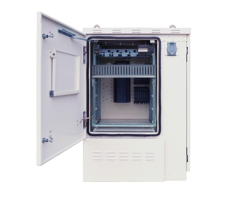
• The FAC 3200 can accommodate equipment in the front compartment, as well as auxiliary and complementary options in the rear compartment and the splice chamber. The 23” equipment racks in front, rear and splice compartments, allow for a variety of deployment options.
• Designed to seamlessly integrate a variety of standard options that are expected in remote cabinets, such as the rectifier system, battery warmers and field upgradeable fiber bulkheads
• Supports a variety of cabinet mounting options including pad, pole, wall or H-frame, eliminating concern with right-of-way issues and problematic installation locations
Protection
• Telcordia GR-487 compliant and UL-60950/UL-50 spec
• Environmentally sealed design protects internal equipment investment from dust and rain
• Rated for deployments in harsh environments per GR-487: -40°F to +115°F (-40°C to +46°C)
Access
• Provides 3-point latching doors for quick access to all three compartments
• Designed to allow access to all complementary elements of a remote outdoor cabinet deployment such as the copper or fiber cables, fiber splicing and distribution modules, power and DC distribution systems, AC power and battery charge breakers, AC outlet, etc.
• Door security and hardware features designed to protect from vandalism and theft
Investment
• The FAC 3200 is designed for modular expansion, allowing for cost effective expansion of services in the future
• Cabinet engineered features designed to ensure ease of maintenance and eliminate service interruptions
• Provides an ideal platform for the migration of copper access services to fiber access infrastructure and electronics
FieldSmart ® Fiber Active Cabinet (FAC) 3200
Technical Specifications
FieldSmart FAC 3200
Dimensions
Weight
Mounting Options
AC Power Center Options
AC/DC Rectifier Option
Cooling/Environmental
Wired Capacity
Fiber Management Options
Copper Protection Options
38”W x 43”D x 55”H
560 lbs. (Equipped with Northstar 170 Ah batteries: 1000 lbs.)
Pad, Pole, H-frame, Wall, 3rd Party Pedestal
Power feed: 240 VAC single phase, 60-Amp service with UL listed service disconnect. Redundant AC feeds to rectifier. Redundant DC feeds to systems. Low voltage DC disconnect. (–42V), high-power Joslyn surge protector.
Eltek CC9S-ANL-VC Compact Power System 120 Amp max. total capacity (90A N+1). Rectifier modules: (4) 30 Amp modules supported (Configured part numbers include two modules).
Option 1: 1800 watt (6142 Btu/h) cooling capacity with Dantherm door mount heat exchanger, as per GR-487 generic requirement
Option 2: 1800 watt (6000 Btu/h) Dantherm door mount air conditioner. Air conditioner module is not GR-487 rated.
Ambient temperature per GR-487: -40°F to +115°F (-40°C to +46°C)
Fiber: Up to 576 subscriber fiber terminations utilizing bulkhead option. Up to 18 integrated PON splitters.
Copper: Up to 576 copper lines with MS2 or 710 splice options
12-or 24-position Clearfield fiber splice and distribution on 19/23” mount. Support for in-cabinet GPON and ActiveE fiber management: Up to 576 position fiber distribution in 48-, 96-, 144- or 288-port increment assemblies; SC/APC connector, loose tube or ribbon. Up to eighteen integrated 1x2, 1x16, 1x32 GPON Splitters (optional).
Standard 5-pin protection blocks — modular in 48-pair increments. Up to (12) 48-pair protection blocks. Available Rack Units 32 RU 23” rack with optional 19” vertical frames
UL-60950, Standard for Safety, Issue 1, April 1, 2003 CAN/CSA-C22.2 No. 60950 EMC FCC Part 15 Class A ICES-003 Class A
Safety and Compliance
Telcordia, GR-63-CORE, NEBS Telcordia, GR-487, Generic Requirements for Electronic Equipment Cabinets
Pre-Configured Part Numbers
Part Number Description
R-3ZFC-ZZ1Z-ZZZ-ZZZ-ZZ
R-3ZFE-ZZ1Z-ZZZ-ZZZ-ZZ
FieldSmart Fiber Active Cabinet, FAC 3200 Enclosure, Standard 23 Inch Equipment Rack, 1800 watt (6142 Btu/h) Heat Exchanger, No Load Center, No Rectifier, Supports 1 Battery String, No Bulkhead
FieldSmart Fiber Active Cabinet, FAC 3200 Enclosure, Standard 23 Inch Equipment Rack, 1800 watt (6142 Btu/h) Air Conditioner, No Load Center, No Rectifier, Supports 2 Battery String, No Bulkhead
FieldSmart ® Fiber Active Cabinet (FAC) 3200
Configured Part Numbers
Disclaimer/Note: Paper configurator shown is for reference only and should not be used to configure a saleable product configuration. All options shown on paper configurators may not be available or compatible with other options listed. Please contact your Clearfield representative for assistance in product configurations.
Mounting Options
Fiber Active Cabinet (FAC) 5400
FieldSmart ® Application
The FieldSmart Fiber Active Cabinet (FAC) 5400 is the largest cabinet offering from Clearfield. It has been designed with the philosophy of modularity and flexibility, while maintaining a maximum cooling capability for the active electronics. Compliant with GR-487, the FAC 5400 is the ideal outdoor cabinet solution for the harshest outdoor conditions, providing a sealed internal environment where external air and humidity are completely isolated from the electronic equipment.
Description
The FAC 5400 is an environmentally-controlled enclosure constructed of powder-coated aluminum. The FAC 5400 cabinet’s equipment compartment features a 23”, 27RU swing frame front and rear, accommodating up to 54RU of active electronics equipment. The FAC 5400 provides up to 1,152 internal fiber distribution ports for subscriber PON deployments along with complementary splitter capacity. The FAC 5400 accepts local AC power and uses either two door mounted integrated air-to-air heat exchangers and DC-powered fans or integrated DC-powered air conditioners to cool the equipment inside the cabinet. A vented, integrated-cabinet compartment below the equipment compartment houses optional batteries.
Features and Benefits
Integrity
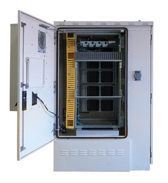
• The FAC 5400 can accommodate equipment in the front compartment, as well as auxiliary and complementary options in the rear compartment and the splice compartment. The 23” equipment racks in front, rear and splice compartment, allow for a variety of deployment options.
• Designed to seamlessly integrate a variety of standard options that are expected in remote cabinets, such as the rectifier system, battery warmers and field upgradeable fiber bulkheads
Protection
• Telcordia GR-487 compliant and UL-60950/UL-50 spec
• Environmentally sealed design protects internal equipment investment from dust and rain
• Rated for deployments in harsh environments per GR-487: -40°F to +115°F (-40°C to +46°C)
Access
• Equipment swing frames provide for front and rear access to the equipment within the cabinet
• Designed to allow access to all complementary elements of a remote outdoor cabinet deployment such as the copper or fiber cables, fiber splicing and distribution modules, power and DC distribution systems, AC power and battery charge breakers, AC outlet, etc.
• Door security and hardware features designed to protect from vandalism and theft
Investment
• The FAC 5400 is designed for modular expansion, allowing for cost effective expansion of services in the future
• Cabinet engineered features designed to ensure ease of maintenance and eliminate service interruptions
FieldSmart ® Fiber Active Cabinet (FAC) 5400
Technical Specifications
FieldSmart FAC 5400
Dimensions
49”W x 58”D x 74”H
Weight 1,175 lbs. (Not including batteries)
Mounting Options Pad
AC Power Center Options
Optional AC/DC Rectifier Options
Cooling/Environmental
Wired Capacity
Fiber Management Options
Power feed: 240 VAC single phase, 60-Amp service with UL listed service disconnect. Redundant AC feeds to rectifier. Redundant DC feeds to C7 shelf. Low voltage DC disconnect. (–42V) High power AC surge protection (ABB).
Eltek CC9S-ANL-VC Compact Power System 120 Amp max. total capacity (90A N+1). Rectifier modules: (4) 30 Amp modules supported (Configured part numbers include two default).
Option 1: Dantherm door mount heat exchanger options (1800 Watts/6000 Btu/h – up to two 3600 Watts/12,000 Btu/h total with front and rear door options).
Option 2: Dantherm door mount air conditioner options (1800 Watts/6000 Btu/h – up to two 3600 Watts/12,000 Btu/h total with front and rear door options).
Ambient temperature per GR-487: –40° F to +115° F (-40°C to +46°C)
Fiber: Up to 1152 subscriber fiber terminations utilizing bulkhead options. Up to 36 integrated PON splitters.
Copper: Up to 1152 copper lines with MS2 or 710 splice options
12-or 24-position Clearfield fiber splice and distribution on 19/23” mount. Support for in-cabinet GPON and ActiveE fiber management: Up to 1152 position fiber distribution in 48-, 96-, 144-, or 288-port increments assemblies; SC/APC connector, loose tube or ribbon. Up to 36 integrated 1x2, 1x16, 1x32 GPON Splitters (optional).
Copper Protection Options Standard 5-pin protection blocks — modular in 48-pair increments, up to (24) 48-pair protection blocks Available Rack Units 54RU 23” swing frame rack with optional 19” vertical frames
UL-60950, Standard for Safety, Issue 1, April 1, 2003 CAN/CSA-C22.2 No. 60950 EMC FCC Part 15
Class A ICES-003 Class A
Safety and Compliance
Telcordia, GR-63-CORE, NEBS Telcordia, GR-487, generic requirements for electronic equipment cabinets
Pre-Configured Part Numbers
Part
R-4ZFC-ZZ1Z-ZZZ-ZZZ-ZZ
R-4ZFD-ZZ1Z-ZZZ-ZZZ-ZZ
R-4ZFE-ZZIZ-ZZZ-ZZZ-ZZ
R-4ZFF-ZZ1Z-ZZZ-ZZZ-ZZ
FieldSmart Fiber Active Cabinet, FAC 5400 Enclosure, Standard 23 Inch Equipment Rack, 1800 watt (6142 Btu/h) Heat Exchanger, No Load Center, No Rectifier, Supports 1 Battery String, No Bulkhead
FieldSmart Fiber Active Cabinet, FAC 5400 Enclosure, Standard 23 Inch Equipment Rack, 3600 watt (12,284 Btu/h) Heat Exchanger, No Load Center, No Rectifier, Supports 1 Battery String, No Bulkhead
FieldSmart Fiber Active Cabinet, FAC 5400 Enclosure, Standard 23 Inch Equipment Rack, 1800 watt (6,000 Btu/h) Air Conditioner, No Load Center, No Rectifier, Supports 1 Battery String, No Bulkhead
FieldSmart Fiber Active Cabinet, FAC 5400 Enclosure, Standard 23 Inch Equipment Rack, 3600 watt (12,000 Btu/h) Air Conditioner, No Load Center, No Rectifier, Supports 1 Battery String, No Bulkhead
FieldSmart ® Fiber Active Cabinet (FAC) 5400
Configured Part Numbers
Disclaimer/Note: Paper configurator shown is for reference only and should not be used to configure a saleable product configuration. All options shown on paper configurators may not be available or compatible with other options listed. Please contact your Clearfield representative for assistance in product configurations.
FieldSmart®
FiberFlex 600
Application
Clearfield’s FieldSmart FiberFlex 600 is a compact, small form factor design optimized for a variety of powered cabinet deployment scenarios. The cabinet is designed to configure for numerous applications including remote OLTs with PON distribution, wireless base stations with fiber backhaul aggregation and active network equipment with back-up power needs, utilizing a flexible layout.
Whether supporting a less densely populated, rural deployment or an urban environment, pairing the FiberFlex 600 with a FieldSmart PON cabinet delivers the power and fiber connectivity to support the exact network requirements.
The cabinet’s reduced footprint allows for a simplified installation with placement into any application with pad or pole mount options. Designed to meet GR-487 requirements, the rightsized FiberFlex 600 is an ideal outdoor cabinet solution for the harshest environments.
Description
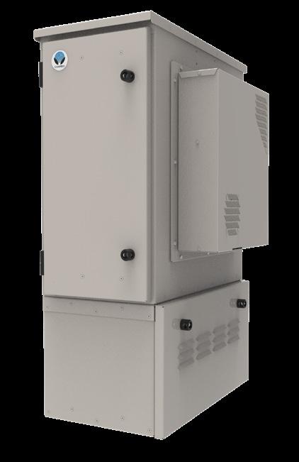
The FiberFlex 600 is an all-in-one design, capable of integrating fiber and active equipment powered by AC Power Supply converter or DC rectification. The FiberFlex 600 equipment bay features a 19-inch vertical equipment rack to provide options for up to 6RU of equipment rack space including 2.5RU for active equipment deployment needs.
The FiberFlex 600 provides up to 72 internal fiber distribution ports for subscriber fiber connectivity. This unique design also offers an optional integrated AC Load Center with generator plug for back-up power (pad mount only).
Features and Benefits
Flexibility (Optional Features)
• Cooling options include Heat Exchanger and HVAC (future release)
• AC power system with main breaker, 8-slot load center, and surge protection
• Optional 30 Amp generator plug for long run time back-up power
• Both rectifier and DC power converter solutions are sized to meet application and distribution needs
• Batteries sized to meet power requirements and back-up power time
• Environmental alarm wiring
Space Utilization
• Interior rack is 19-inch EIA standard spacing
• Mounting options – pad mount or pole mount
Integrity
• Closed-cell door gasket is attached to cabinet frame compliant with NEMA standards
• Stainless steel hardware to prevent corrosion
• Grounding provisions: ground straps for doors and master ground bar mounted in cabinet
• 15 Amp convenience receptacle
• Two lifting eyes on the cabinet to enable ease of installation
• GR-487 compliant powder coating of cabinet
Access
• Fiber-first design for access, storage, routing, and protection of fiber
• Standard is Clearview Blue Cassette (supports patch-only applications)
• Cable entry ports with removable plate to facilitate ease of installation when mounted on concrete pad
• Adjustable door stays from 90-degree to 180-degree openings
• Front and rear door with security padlock hasp with ¼-turn sealing mechanism
FieldSmart® FiberFlex 600
Technical Specifications
FieldSmart FiberFlex 600
Dimensions
Weight
Mounting Options
AC Power Center Options
AC/DC Rectifier Option
Base Cabinet with Battery Base: 40” H x 14” W x 26” D
Base Cabinet without Battery Base: 27” H x 14” W x 26” D
Cabinet with Battery Base: 100 lbs.
Cabinet without Battery Base: 50 lbs.
Pour-in-Place Pad Template or Pole Mount
024034 - Assy, pour in place template, FF600
AC Power feed: 240 VAC single phase, 50/60Hz, 30 Amp service with UL listed service panel. Optional 30 Amp generator connection.
High power AC surge protection
Configurable Rectifier Option: 1RU ABB SPS Slimline Series w/ (10) GMT, (2) Batt. Brkr, (Up to 2) 1000W Rectifier Modules (Configured part numbers include two modules)
Configurable Power Supply Option: 1RU 600W Power Supply w/ (10) GMT
Battery Options 140-00039 - Battery string kit (ENERSYS) 4 x SBS B14 62AH - front access
Battery Capacity
Cooling/Environmental
Battery base option designed to accommodate single 60 Amp-hour front terminal batteries with optional secondary battery base solution only in pad mount configuration.
Configurable Heat Exchanger: 600W (17W/F) Heat Exchanger (HEX)
Configurable Air-Conditioner: 2000 BTU, DC Powered Air Conditioner with Heat (Future Release)
Wired Fiber Capacity Up to 72 Distribution; Standard cassette is Clearview Blue for patch only
Available Rack Units 6RU available depending on configuration selected; 2.5RU dedicated for active equipment
Safety and Compliance Designed to meet GR-487, pending UL508a and UL50
FiberFlex 1700
FieldSmart® Application
Clearfield’s FieldSmart FiberFlex 1700 is optimized as a fiber-first design for a variety of powered cabinet deployment scenarios. The cabinet is designed to configure for numerous applications including remote OLTs with PON distribution, wireless base stations with fiber backhaul aggregation and active network equipment with back-up power needs, utilizing a flexible vertical layout and a modular design that allows for networks to scale for the future growth.
The cabinet’s footprint makes it easy to drop into any application with a pad or vault mount option. Designed to meet GR-487 requirements, the FiberFlex 1700 is the ideal outdoor cabinet solution for the harshest environments. At 48”, the FiberFlex 1700 was designed to meet more stringent local permit height restrictions.
Description

The FiberFlex 1700 is an all-in-one design, capable of integrating fiber, power (AC & DC) and active equipment. This cabinet features flexible vertical options to meet a wide variety of deployment environments and is scalable for future growth. The FiberFlex 1700 equipment bay features a 19” or 23” vertical equipment rack to provide options for:
• 25RU - no separate sealed battery section
• 17RU - with 1 string of batteries
The FiberFlex 1700 provides up to 432 internal fiber distribution ports for subscriber PON deployments, along with complementary splitter capacity. The FiberFlex 1700 accepts local AC power via the integrated AC Load Center with generator plug for back-up power.
Features and Benefits
Flexibility (Optional Add Features)
• Environmental controls include HVAC, heat exchangers, direct air cooling. Configured to meet application and location needs.
• AC power system with main breaker, 12 slot load center and surge protection.
• 30 amp Generator Plug for long run time back-up power.
• DC power source sized to meet application and distribution needs.
• Batteries sized to meet power requirements and back-up power time.
• Internal LED light to provide better visual experience with equipment installed on the rack.
• Intrusion alarms.
Space Utilization
• Interior rack can be 19’ or 23” EIA standard spacing.
• Various mounting options – pad mount, vault mount.
Integrity
• Closed cell door gasket is attached to cabinet frame -- compliant with NEMA standards.
• Stainless steel hardware to prevent corrosion.
• Grounding provisions - with ground straps for doors and master ground bar mounted in cabinet.
• 20 amp convenience receptacle.
• Sunshield to reduce the effects of solar loading.
• Lifting eyes on four corners of the cabinet to enable ease of installation.
• GR-487 compliant cabinet powder coating.
• Designed, tested and certified to GR-487.
Access
• Fiber-first design for excess storage, routing and protection of fiber
• Fiber counts from 12 to 432, splitters cages holding up to 18 splitters.
• Standard is Clearview® Blue Cassette (patch & splice) (patch).
• Cable entry ports with removable plate to facilitate ease of installation when using a vault or mounted on concrete pad.
• Stainless steel door stays adjustable from 90 deg to 120 degree openings.
• Front and rear door with security padlock hasp with ¼ turn sealing mechanism.
• 3” mounting plinth to allow craft-friendly installation.
FieldSmart® FiberFlex 1700
Technical Specifications
FieldSmart FiberFlex 1700
Dimensions
Base cabinet: 48” H x 30” W x 36” D, mounting plinth adds 3”
Weight Cabinet: 400 lbs.
Mounting Options
AC Power Center Options
AC/DC Rectifier Option
Battery Capacity
Cooling/Environmental
Wired Fiber Capacity
Fiber Management Options
Pour-in-Place Pad Template, or Split Lid Vault
AC Power feed: 240 VAC single phase, 50/60Hz, 125 Amp service with UL listed service panel
High power AC surge protection
ABB SPS Slimline Series with various distribution models. (Configured part numbers include two modules)
• Standard: (12) GMT, (2) Load Brkr (60A Max), (2) Batt. Brkr (Up to 3) 1600W Rectifier Modules
• Optional: (24) GMT, (2) Batt. Brkr (Up to 3) 1600W Rectifier Modules
Delta Eltek FPS System
• FPSK59I-ANL-VC distribution with (10) GMT, (4) Load Brkr, (2) Batt. Brkr, Controller (Up to 6) 1800W Rectifier Modules (Configured part numbers include two modules)
Designed to accommodate 60Ah to 200Ah front terminal batteries. For top terminal capacity, contact Clearfield for further information.
Heat Exchanger Option: 1000W (47W/C) HEX, up to 2 for a total maximum cooling capacity of 2000W.
Air-Conditioning Option: 4000 BTU AC or DC powered Air-Conditioner with Heat. Up to 2 AC units per cabinet configuration.
Direct Air Cooling (DAC) Option: Direct Air Cooling Fan – Non-environmentally sealed.
Up to 432 Distribution; Standard cassette is Clearview Blue for patch only. Available in 50, 75, or 100foot tail increments.*
*Note: All available tail lengths are measured from the rear of the fiber panel installed in the cabinet
Up to 432 position fiber distribution in 144 or 288 port increments, vatious connector and distribution options. Splitters and WDM, various ratios are available. Vertical and horizontal rack rail fiber and cable management
Available Rack Units 25RU, 17RU, depending on configuration selected Safety and Compliance GR-487, pending UL508a
Mounting Options
Mounting Option Part Number Description Pad Template 150-00027 FiberFlex 3000/1700 Pour-in-Place Template
Splitter Options
Part Number Description
KC1-CAA
Ruggedized Splitter Module, Loaded with (1) 1X32 Spliltter, SC/APC Connectors, Front Pigtail Input(s) and Outputs, Bend Insensitive Fiber, Ruggedized Jacket
FieldSmart® FiberFlex 1700
140-00002
140-00010
140-00038
150-00009
BATTERY STRING KIT (NORTHSTAR), 4 x NSB-100FT RED 100 AH - FRONT ACCESS
BATTERY STRING KIT (NORTHSTAR), 4 x NSB-170FT RED 170 AH - FRONT ACCESS
BATTERY STRING KIT (ENERSYS), 4 x SBS190F 190 AH - FRONT ACCESS
BATTERY STRING KIT (NORTHSTAR) 4 x NSB155FT RED 155AH - FRONT ACCESS
FieldSmart ®
FiberFlex 2000
Application
Clearfield’s FieldSmart FiberFlex 2000 enclosure has been designed from the ground up for maximum flexibility, scalability and space utilization. Optimized for fiber service delivery from 144 to 576 fiber ports utilizing the compact patch only Clearview Black Cassette, the FiberFlex 2000 is a fiber-first design for a variety of powered cabinet deployment scenarios such as the network edge, wireless backhaul and active ethernet networks. The cabinet’s small footprint makes it easy to drop into any application in any location. Designed to comply to GR-487, the FiberFlex 2000 is the ideal outdoor cabinet solution for the harshest outdoor conditions, providing a sealed internal environment where external air and humidity are completely isolated from the electronic equipment.
Description
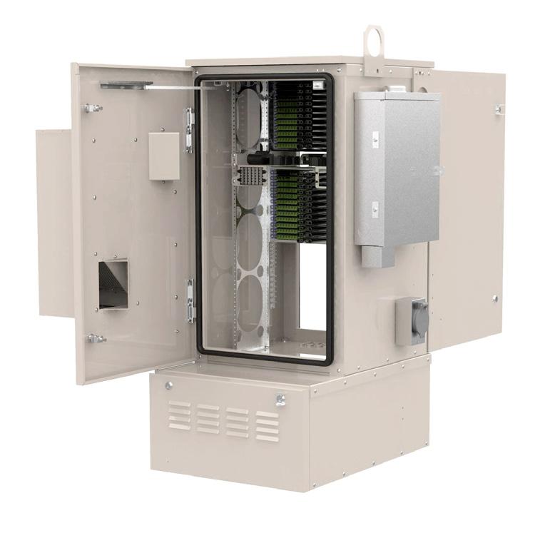
The FiberFlex 2000 is an environmentally-controlled enclosure constructed of powdercoated aluminum. The FiberFlex 2000’s equipment bay features a 19” vertical equipment rack, accommodating up to 20RU of active electronics equipment. The FiberFlex 2000 provides up to 576 internal fiber distribution ports for subscriber PON deployments, along with complementary splitter capacity. The FiberFlex 2000 accepts local AC power and features an external AC Load Center. A door-mounted, integrated air-to-air heat exchanger and air conditioner provides environmental thermal control for the equipment inside the cabinet. A separate, vented, under-cabinet compartment houses optional batteries. A second battery compartment can be added for additional backup capabilities.
Features and Benefits
Flexibility
• External load center – Simplifies and separates AC connection on site
• Multiple fiber counts – 144 to 576 fiber ports in a single cabinet (Clearview Black Cassette standard)
• Various mounting options – Pad mount or pole mount
• Stackable backup battery bays – Add additional battery compartment to double available backup time
Space Utilization
• Only 54” x 24” x 35” to fit nearly any deployment scenario
• Optimized internal space utilization for maximum equipment capabilities and fiber port count
Integrity
• Designed to comply to GR-487 and NEMA 4 for matchless protection in the harshest environments
• Heat Exchanger and Air Conditioner configurations available
• Factory integration and testing of the AC Load Center, Rectifier, Backup Battery Harness and Heat Exchanger/Air Conditioner
Access
• Provides front and rear doors for full access to internal equipment
• External AC Load Center for easy access and optimal interior space utilization
• Fiber-first design for access storage and routing of fiber (or copper) cables and accessories, such as splitters and WDMs
• Door security and hardware features designed to protect equipment from vandalism and theft
• Door integrity alarm standard
FieldSmart ® FiberFlex 2000
Technical Specifications
FieldSmart FiberFlex 2000
Dimensions
Weight
Mounting Options
AC Power Center Options
Base cabinet with Battery Compartment: 54”H x 24”W x 35”D
Base Cabinet with 2nd Battery Compartment Option: 66”H x 24”W x 35”D
Cabinet with Battery Compartment: 250 lbs. Equipped with one 155 Ah battery string: 650 lbs.
Pour-in-Place Pad Template, FUTURE: Pole Mount
AC Power feed: 240 VAC single phase, 50/60HZ, 125 Amp service with UL listed service panel.
High power AC surge protection (Joslyn)
AC/DC Rectifier Option
Battery Capacity
Cooling/Environmental
Fiber Management Options
Available Rack Units
Standard Rectifier: Eltek Flatpack S (FPS) 1RU -48vdc Rectifier System, Two 1000-Watt rectifier modules, autosenses and adjusts for low and high AC input
Optional: Eltek Flatpack S (FPS) 2RU -48vdc Rectifier System, Two 1800-Watt rectifier modules, autosenses and adjusts for low and high AC input
Smartpack S Controller
Note: All Configured Cabinet part numbers include Qty (2) Rectifier Modules
Designed to accommodate (2) strings of Northstar NSB 155FT RED batteries. One string support in the standard battery compartment. Dual battery string support using expanded backup option with second battery compartment orders. (Increases capacity to 310Ah total backup).
For all other battery types required, compartment space is as follows: 11.2”H x 5”W x 22”D
Heat Exchanger: 1000-Watt cooling capacity with Dantherm door mount heat exchanger
Air Conditioner: 4K BTU Dantherm AC or DC powered air conditioner options available
Ambient operating temperature range: -40°C to +46°C (-40°F to +115°F)
Up to 576 position fiber distribution in 144 or 288-port increments, SC/APC connector, loose tube or ribbon
Up to eighteen integrated splitters in various ratios available
Configurable transport module for fiber separation of subscriber and active equipment transport
20RU in a standard 19” rack
6RU with full 576 fiber distribution SC ports and rectifier option
Safety and Compliance GR-487, UL508a, UL50, and UL50E
Mounting Options
Mounting Option
Splitter Options
FiberFlex 3000
FieldSmart ® Application
Clearfield’s FieldSmart FiberFlex 3000 is optimized as a fiber-first design for a variety of powered cabinet deployment scenarios. The cabinet is designed to configure for numerous applications including remote OLTs with PON distribution, wireless base stations with fiber backhaul aggregation and active network equipment with back-up power needs, utilizing a flexible vertical layout and with a modular design that allows for networks to scale for the future growth.
The cabinet’s footprint makes it easy to drop into any application with a pad or vault mount option. Designed to meet GR-487 requirements, the FiberFlex 3000 is the ideal outdoor cabinet solution for the harshest environments.
Description
The FiberFlex 3000 is an all-in-one design, capable of integrating fiber, power (AC & DC) and active equipment. This cabinet features flexible vertical options to meet a wide variety deployment environments and is scalable for future growth. The FiberFlex 3000 equipment bay features a 19” or 23” vertical equipment rack to provide options for:
• 36RU active electronics and passive equipment with no batteries
• 30RU with 1 string of batteries
• 20RU with 2 strings of batteries
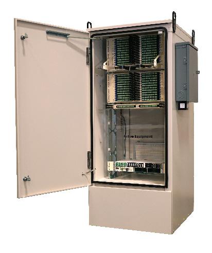
The FiberFlex 3000 provides up to 864 internal fiber distribution ports for subscriber PON deployments, along with complementary splitter capacity. The FiberFlex 3000 accepts local AC power via the integrated AC Load Center with generator plug for back-up power.
Features and Benefits
Flexibility (Optional Add Features)
• Environmental controls include HVAC, heat exchangers, direct air cooling. Configured to meet application and location needs
• AC power system with main breaker, 12 slot load center and surge protection
• 30 amp Generator Plug for long run time back-up power
• DC power source sized to meet application and distribution needs
• Batteries sized to meet power requirements and back-up power time
• Internal LED light to provide better visual experience of equipment installed on the rack
• Door alarms dry contacts normal closed to provide intrusion alarm
Space Utilization
• Interior rack can be 19’ or 23” EIA standard spacing
• Various mounting options – pad mount, vault mount
Integrity
• Closed cell door gasket and attached to cabinet frame compliant with NEMA standards
• Stainless steel hardware to prevent corrosion
• Grounding provisions - with ground straps for doors and master ground bar mounted in cabinet
• 15 amp convenience quad receptacle
• Sunshield to reduce the effects of solar loading
• Lifting eyes on four corners of the cabinet to enable ease of installation
• GR-487 compliant powder coating of cabinet
• Designed, tested and certified to GR-487
Access
• Fiber-first design for access storage, routing and protection of fiber
• Fiber from 144 to 864 with splitters or WDMs panel
• Standard is Clearview® Blue Cassette (patch only)
• Cable entry ports with removable plate to facilitate ease of installation when using a vault or mounted on concrete pad
• Stainless steel door stays adjustable from 90 degree to 120 degree openings
• Front and rear door with security padlock hasp with ¼ turn sealing mechanism
• 3-inch mounting plinth to craft-friendly installation
FieldSmart ® FiberFlex 3000
Technical Specifications
FieldSmart FiberFlex 3000
Dimensions
Base cabinet with Battery Compartment: 72”H x 30”W x 36”D
Weight Cabinet: 600 lbs.
Mounting Options
AC Power Center Options
AC/DC Rectifier Option
Battery Capacity
Cooling/Environmental
Wired Fiber Capacity
Fiber Management Options
Available Rack Units
Pour-in-Place Pad Template, or Split Lid Vault
AC Power feed: 240 VAC single phase, 50/60Hz, 125 Amp service with UL listed service panel.
High power AC surge protection
ABB SPS Slimline Series with various distribution models. (Configured part numbers include two modules)
• Standard: (12) GMT, (2) Load Brkr (60A Max), (2) Batt. Brkr (Up to 3) 1600W Rectifier Modules
• Optional: (24) GMT, (2) Batt. Brkr (Up to 3) 1600W Rectifier Modules
Delta Eltek FPS System
• FPSK59I-ANL-VC distribution with (10) GMT, (4) Load Brkr, (2) Batt. Brkr, Controller (Up to 6) 1800W Rectifier Modules (Configured part numbers include two modules)
Designed to accommodate 80AH to 200AH front terminal batteries. For top terminal capacity, contact Clearfield for further information.
Heat Exchanger Option: 1800W (99W/C) HEX, up to 2 for a total maximum cooling capacity of 3600W.
Air-Conditioning Options: 6000 BTU AC or DC powered Air-Conditioner with Heat. Up to 2 AC units per cabinet configuration.
Direct Air Cooling (DAC) Option: Direct Air Cooling Fan – Non-environmentally sealed.
Up to 864 Distribution; Standard cassette is Clearview Blue for patch only. Available in 50, 75, or 100foot tail increments. *
* Note: All available tail lengths are measured from the rear of the fiber panel installed in the cabinet.
Up to 864 position fiber distribution in 144 or 288-port increments, various connector and distribution options. Splitters and WDM in various ratios available. Vertical and horizontal rack rail fiber and cable management
Configurable transport module for fiber separation of subscriber and active equipment transport
36RU, 30RU, 20RU, depending on configuration selected.
Safety and Compliance GR-487, UL508a, UL50, and UL50E
Configured Part Numbers - “Under Construction”
Mounting Options
FieldSmart ® FiberFlex 3000
Splitter Options
Part Number
KC1-CAA
Battery Options
Part Number
140-00010
140-00038
Description
Ruggedized Splitter Module, Loaded with (1) 1X32 Splitter, SC/APC Connectors, Front Pigtail Input(s) and Outputs, Bend Insensitive Fiber, Ruggedized Jacket.
Description
Battery String Kit (NORTHSTAR), 4 x NSB-170FT RED 170 AH - Front Access
Battery String Kit (ENERSYS), 4 x SBS190F 190 AH - Front Access
FieldSmart®
FiberFlex 1700 - Convergent
Application
Clearfield’s FiberFlex 1700 Convergent configurations are expertly crafted with a fiber-first design, ensuring optimal separation of your Fiber Distribution from active equipment across various powered cabinet deployment scenarios. This versatile multi-bay cabinet supports a wide range of applications, enabling providers to position more active equipment closer to the network edge.
Designed, tested, and certified to meet GR-487 standards, the FiberFlex 1700 Convergent models stand out as the premier outdoor cabinet solution for even the harshest environments.
Description
The FiberFlex 1700 Convergent series uses an all-in-one design approach capable of integrating fiber, power (AC & DC) and active equipment using multiple cabinet bays to separate power and active equipment from the fiber distribution. This cabinet offers multiple configuration options, supporting diverse deployment scenarios and featuring a 19” or 23” vertical equipment rack to accommodate the following applications:
• 34RU (17RU X 17RU): Capable of supporting two strings of batteries, one in each enclosure.
• 42RU (17RU X 25RU): Capable of supporting one battery string in the 17RU enclosure.
• 50RU (25RU X 25RU): Capable of supporting lithium battery deployments.
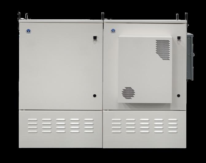
The FiberFlex 1700 Convergent provides two modular enclosures, one enclosure designed to support all customer powered equipment needs and a separate enclosure supporting fiber distribution. Up to 432 internal fiber distribution ports in the 34RU configurations, and up to 576 internal fiber distribution ports in the 42RU and 50RU configurations. The FiberFlex 1700 Convergent offers optional splitter capacity with an integrated 1RU splitter tray, supporting up to 9 ruggedized splitters. For configurations that include splitter support, one integrated splitter tray is provided for every 288 fiber distribution ports. The FiberFlex 1700 Convergent uses local AC power via the integrated AC Load Center with optional generator plug for back-up.
Features and Benefits
Flexibility (Optional Features)
• Environmental controls include HVAC, heat exchangers, direct air cooling. Configured to meet application and location needs.
• AC power system with main breaker, 12 slot load center and surge protection
• 30-amp Generator Plug for long run time back-up power
• DC power source sized to meet application and distribution needs
• Batteries sized to meet power requirements and back-up power time (supporting both Lithium and VRLA deployments)
• Internal LED light in the powered equipment bay to provide easier equipment installation in dark/low light environments
Space Utilization
• Interior rack can be 19” or 23” EIA standard spacing
• Multi-bay cabinet configurable for pad-mount applications only
Integrity
• Closed cell door gasket is attached to cabinet frame compliant with NEMA standards
• Grounding provisions: ground straps for doors and master ground bar mounted in cabinet
• 15-amp convenience quad receptacle
• Solar Shield enclosure lid to reduce the effects of solar loading
• Lifting eyes on four corners of each cabinet to enable ease of installation and connection between cabinets
• Designed, tested, and certified to GR-487
Access
• Fiber-first design for access storage, routing, and protection of fiber
• Internal fiber distribution from 144 to 576 using the Clearview® Blue Cassette with optional splitter tray
• Cable entry ports with removable plate to facilitate ease of installation when using a vault or mounted on concrete pad
• Stainless steel door-stays adjustable from 90-degree to 120-degree openings
• Front and rear door with security padlock hasp and ¼-turn sealing mechanism
• 3-inch mounting plinths for craft-friendly installation
FieldSmart® FiberFlex 1700 - Convergent
Technical Specifications
FieldSmart FiberFlex 1700 - Convergent 34RU
Dimensions
Base enclosures with battery compartments: 51”H x 62”W x 36”D
Total Available Rack Units 34RU (17RU & 17RU in separate enclosures)
• AC load center & AC load center with Generator Connect
• 19” or 23” rack mounting
• Heat exchanger (HEX) or air-conditioning with heater
Configurable Options
Additional Details
• AC/DC Rectifier option configured from 30 amps to 150 amps (consult Clearfield for systems greater than 150 amps)
• Up to 432 fiber distribution ports
• Two battery compartments to support up to two battery strings
• Active equipment enclosure and fiber equipment enclosure shipped separately
• Separate orderable pour-in-place pad template
• Cabinet joining collar included
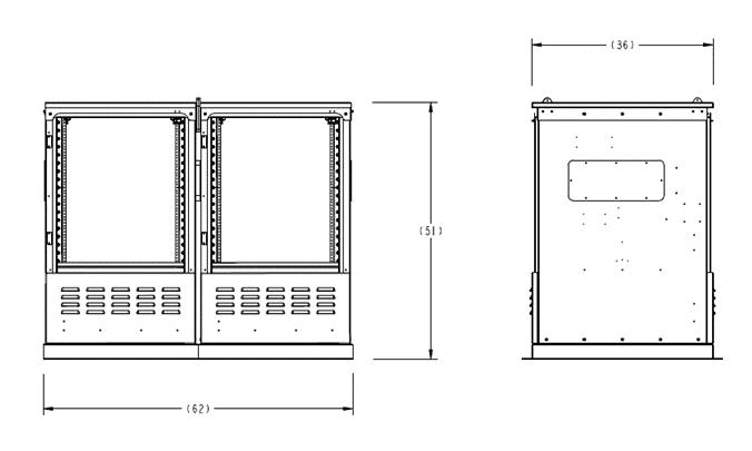
FieldSmart® FiberFlex 1700 - Convergent
Technical Specifications
FieldSmart FiberFlex 1700 - Convergent 42RU
Dimensions
Base enclosures with battery compartments: 51”H x 62”W x 36”D
Total Available Rack Units 42RU (17RU & 25RU in separate enclosures)
• AC load center & AC load center with generator connect
• 19” or 23” rack mounting
• Heat exchanger (HEX) or air-conditioning with heater
Configurable Options
Additional Details
• AC/DC rectifier option configured from 30 amps to 150 amps (consult Clearfield for systems greater than 150 amps)
• Up to 576 fiber distribution ports
• One battery compartments to support one battery string
• Active equipment enclosure and fiber equipment enclosure shipped separately
• Separate orderable pour-in-place pad template
• Cabinet joining collar included
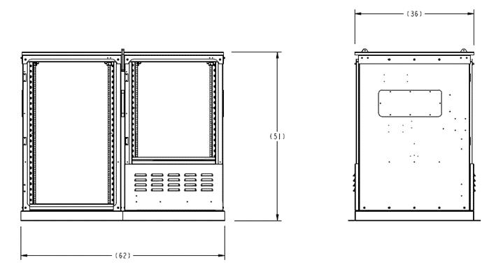
FieldSmart® FiberFlex 1700 - Convergent
Technical Specifications
FieldSmart FiberFlex 1700 - Convergent 50RU
Dimensions
Base enclosures with battery compartments: 51”H x 62”W x 36”D
Total Available Rack Units 50RU (25RU & 25RU in separate enclosures)
• AC load center & AC load center with generator connect
• 19” or 23” rack mounting
• Heat exchanger (HEX) or air-conditioning with heater
Configurable Options
Additional Details
• AC/DC rectifier option configured from 30 amps to 150 amps (consult Clearfield for systems greater than 150 amps)
• Up to 576 fiber distribution ports
• No battery compartments. Integrated support for Lithium deployments available.
• Active equipment enclosure and fiber equipment enclosure shipped separately
• Separate orderable pour-in-place pad template
• Cabinet joining collar included
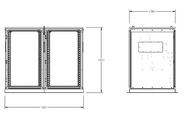
FieldSmart ®
FiberFlex 3000 - Convergent
Application
Clearfield’s FiberFlex 3000 Convergent configurations are expertly crafted with a fiber-first design, ensuring optimal separation of your Fiber Distribution from active equipment across various powered cabinet deployment scenarios. This versatile multi-bay cabinet supports a wide range of applications, enabling providers to position more active equipment closer to the network edge.
Designed, tested, and certified to meet GR-487 standards, the FiberFlex 3000 Convergent models stand out as the premier outdoor cabinet solution for even the harshest environments.
Description
The FiberFlex 3000 Convergent series uses an all-in-one design approach capable of integrating fiber, power (AC & DC) and active equipment using multiple cabinet bays to separate power and active equipment from the fiber distribution. This cabinet offers multiple configuration options, supporting diverse deployment scenarios and featuring a 19” or 23” vertical equipment rack to accommodate the following applications:
• 60RU (30RU X 30RU): Capable of supporting two strings of batteries, one in each enclosure.
• 56RU (20RU X 36RU): Capable of supporting two battery strings in the 20RU enclosure.
• 72RU (36RU X 36RU): Capable of supporting lithium battery deployments.
• 66RU (30RU X 36RU): Capable of supporting one battery string in the 30RU enclosure.

The FiberFlex 3000 Convergent provides two modular enclosures, one enclosure designed to support all customer powered equipment needs and a separate enclosure supporting fiber distribution. Up to 864 internal fiber distribution ports in the 60RU configurations, and up to 1152 internal fiber distribution ports in the 56RU, 72RU, and 66RU configurations. The FiberFlex 3000 Convergent offers optional splitter capacity with an integrated 1RU splitter tray, supporting up to 9 ruggedized splitters. For configurations that include splitter support, one integrated splitter tray is provided for every 288 fiber distribution ports. The FiberFlex 3000 Convergent uses local AC power via the integrated AC Load Center with optional generator plug for back-up.
Features and Benefits
Flexibility (Optional Features)
• Environmental controls include HVAC, heat exchangers, direct air cooling. Configured to meet application and location needs.
• AC power system with main breaker, 12 slot load center and surge protection
• 30-amp Generator Plug for long run time back-up power
• DC power source sized to meet application and distribution needs
• Batteries sized to meet power requirements and back-up power time (supporting both Lithium and VRLA deployments)
• Internal LED light in the powered equipment bay to provide easier equipment installation in dark/low light environments
Space Utilization
• Interior rack can be 19” or 23” EIA standard spacing
• Multi-bay cabinet configurable for pad-mount applications only
Integrity
• Closed cell door gasket is attached to cabinet frame compliant with NEMA standards
• Grounding provisions: ground straps for doors and master ground bar mounted in cabinet
• 15-amp convenience quad receptacle
• Solar Shield enclosure lid to reduce the effects of solar loading
• Lifting eyes on four corners of each cabinet to enable ease of installation and connection between cabinets
• Designed, tested, and certified to GR-487
Access
• Fiber-first design for access storage, routing, and protection of fiber
• Internal fiber distribution from 144 to 1152 using the Clearview® Blue Cassette with optional splitter tray
• Cable entry ports with removable plate to facilitate ease of installation when using a vault or mounted on concrete pad
• Stainless steel door-stays adjustable from 90-degree to 120-degree openings
• Front and rear door with security padlock hasp and ¼-turn sealing mechanism
• 3-inch mounting plinths for craft-friendly installation
FieldSmart ® FiberFlex 3000 - Convergent
Technical Specifications
FieldSmart FiberFlex 3000 - Convergent 60RU
Dimensions
Base enclosures with battery compartments: 72”H x 62”W x 36”D
Total Available Rack Units 60RU (30RU & 30RU in separate enclosures)
• AC load center & AC load center with generator connect
• 19” or 23” rack mounting
• Heat exchanger (HEX) or air-conditioning with heater
Configurable Options
Additional Details
• AC/DC rectifier option configured from 30 amps to 150 amps (consult Clearfield for systems greater than 150 amps)
• Up to 864 fiber distribution ports
• Two battery compartments to support up to two battery strings
• Active equipment enclosure and fiber equipment enclosure shipped separately
• Separate orderable pour-in-place pad template
• Cabinet joining collar included

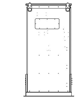
FieldSmart ® FiberFlex 3000 - Convergent
Technical Specifications
FieldSmart FiberFlex 3000 - Convergent 56RU
Dimensions
Base enclosures with battery compartments: 72”H x 62”W x 36”D
Total Available Rack Units 56RU (20RU & 36RU in separate enclosures)
• AC load center & AC load center with generator connect
• 19” or 23” rack mounting
• Heat exchanger (HEX) or air-conditioning with heater
Configurable Options
Additional Details
• AC/DC rectifier option configured from 30 amps to 150 amps (consult Clearfield for systems greater than 150 amps)
• Up to 1152 fiber distribution ports
• Two battery compartments to support up to two battery strings
• Active equipment enclosure and fiber equipment enclosure shipped separately
• Separate orderable pour-in-place pad template
• Cabinet joining collar included

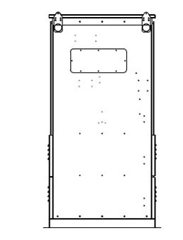
FieldSmart ® FiberFlex 3000 - Convergent
Technical Specifications
FieldSmart FiberFlex 3000 - Convergent 72RU
Dimensions
Base enclosures with battery compartments: 72”H x 62”W x 36”D
Total Available Rack Units 72RU (36RU & 36RU in separate enclosures)
• AC load Center & AC load center with generator connect
• 19” or 23” rack mounting
• Heat exchanger (HEX) or air-conditioning with heater
Configurable Options
Additional Details
• AC/DC rectifier option configured from 30 amps to 150 amps (consult Clearfield for systems greater than 150 amps)
• Up to 1152 fiber distribution ports
• No battery compartments. Integrated support for Lithium deployments available
• Active equipment enclosure and fiber equipment enclosure shipped separately
• Separate orderable pour-in-place pad template
• Cabinet joining collar included
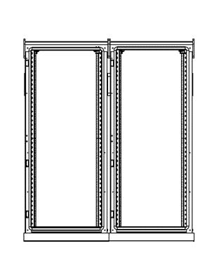
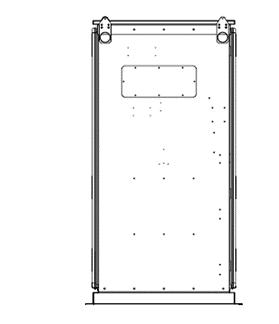
62” 36”
72”
FieldSmart ® FiberFlex 3000 - Convergent
Technical Specifications
FieldSmart FiberFlex 3000 - Convergent 66RU
Dimensions
Base enclosures with battery compartments: 72”H x 62”W x 36”D
Total Available Rack Units 66RU (30RU & 36RU in separate enclosures)
• AC load center & AC load center with generator connect
• 19” or 23” rack mounting
• Heat exchanger (HEX) or air-conditioning with heater
Configurable Options
Additional Details
• AC/DC rectifier option configured from 30 amps to 150 amps (consult Clearfield for systems greater than 150 amps)
• Up to 1152 fiber distribution ports
• One battery compartment to support one battery string
• Active equipment enclosure and fiber equipment enclosure shipped separately
• Separate orderable pour-in-place pad template
• Cabinet joining collar included
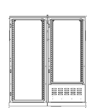
StreetSmart ®
Aerial FDH - 144
Application
When the network deployment plan calls out for an aerial application, Clearfield’s StreetSmart Aerial FDH-144 provides an interconnect environment from the feeder network through the optical passive splitter to the distribution network. Designed specifically for aerial/strand mount applications in the outside plant environment, these enclosures provide a single distribution point to distribute FTTH in rural, urban or dense neighborhoods.
Description
The StreetSmart Aerial FDH-144 is the complete solution for managing up to 144 port distribution fibers for an outside plant FTTx PON application. Factory pre-terminated (1–144, 1–96 or 1– 72) fiber cables eliminates splicing at the terminal and allows the service provider the ability to define and assign the feeder and distribution ports, customizing to each individual deployment.

The Aerial FDH has been designed for aerial or strand mount fiber deployment within the network architecture. The Aerial FDH includes 2 individual hinged covers with four side entrance cable access ports – two on each end.
The factory installed, pre-terminated OSP cable is spliced on the back side of the unit and is separated and secured from the craft accessible feeder and distribution connection ports, located in the front of the enclosure.
The compact design of the Aerial FDH incorporates individual blocks of 12 SC/APC adapters that are housed in multiple sized faceplates, providing maximum configuration capabilities. The symmetrical design of the unit incorporates fiber management and bend-radius protection for all fibers being deployed.
The Aerial FDH has room to hold up to 9 individual compact ruggedized splitter modules, allowing the service provider to add splitters as needed, growing as they go to minimize investment in capital equipment related to the turn-up of revenue-generating circuits. The Aerial FDH is a sealed, free breathing enclosure that provides protection in the harshest OSP environments.
Features and Benefits
Integrity
• Terminations designed, tested and certified to Telcordia GR-326
• Fiber cable certified to GR-20 and GR-409
• Aerial FDH designed, tested and certified to GR-3125
• 100% performance tested for insertion loss, return loss and final mechanical inspection Protection
• Black UV resistant thermoplastic designed to resist corrosion
• Sealed-free breathing terminal provides durability and protection in the OSP environments
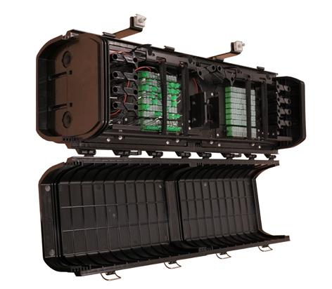


• Separate secure splice chamber, provides protection and security of incoming and outgoing fibers Access
• Four individual secure compartments (2 each - front and rear), separate splices from the drop ports, providing network security
• Hinged front covers allows easy access for installation and network maintenance
• 4 cable entrance/exit ports – 2 on each end
• Factory terminated single 144, 96 or 72 fiber cable allows provider to determine assignment of individual feeder and distribution ports
• Factory installed fiber tail, available in multiple lengths
• Will accept up to 9 individual compact ruggedized splitter modules
• Designation card included
StreetSmart ®
Aerial FDH - 144
Investment
• Customer defined configurations - provides maximum scalability across multiple services classes
• “Grow-as-you-go” capabilities
• Pre-terminated factory polished pigtail assembly - ensures improved network operability when spliced onto the feeder cable
Technical Specifications
StreetSmart Aerial FDH - 144
Dimensions
Material Black UV Resistant Thermoplastic
Weight Approx. 30 lbs.
Feeder/Express Ports 12 or 24 ports
Distribution Ports 144 ports
Cable Entrances 4 – 2 on the left, 2 on the right (Cables can exit on one side only)
Mounting Options Aerial or Strand Mount
Splitter Slots for WaveSmart Ruggedized Splitters 9 Part Number
Connector Types SC/APC, SC/UPC
Cable Types 144/96 OSP fiber Ribbon Outdoor (Non-Rated)
Factory Terminated Fiber
Tails 48 Fiber Feeder and 288 Fiber Distribution Available from 100 to 500 Foot Lengths
Staging Plates Capacity 2 staging plates - will accept up to 48 unused splitter legs Splice Trays 5 Trays, 36 Per tray – 180 Max. Capacity
Configured Part Numbers
Disclaimer/Note: Paper configurator shown is for reference only and should not be used to configure a saleable product configuration. All options shown on paper configurators may not be available or compatible with other options listed. Please contact your Clearfield representative for assistance in product configurations.
StreetSmart ®
Aerial FDH - 144


Ruggedized Splitter Module: Part Number - KE1-CAA
WaveSmart High Density Splitter Module, Loaded with (1) 1X32 Splitter, SC/APC Connectors, Front Pigtail Input(s) and Outputs, Bend Insensitive Fiber, 900um OSP Jacket
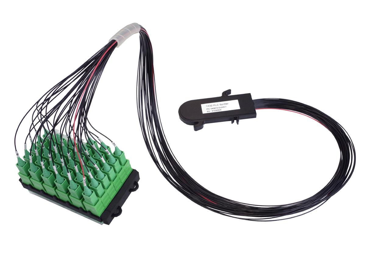
StreetSmart ® Aerial FDH - 288
Application
When the network deployment plan calls out for an aerial application, Clearfield’s StreetSmart Aerial FDH - 288 provides an interconnect environment from the feeder network through the optical passive splitter to the distribution network. Designed specifically for aerial/strand mount applications in the outside plant environment, these enclosures provide a single distribution point to distribute FTTH in rural, urban or dense neighborhoods.
Description
The StreetSmart Aerial FDH - 288 is the complete solution for managing up to 288 port distribution fibers for an outside plant FTTx PON application. Factory pre-terminated (1288 or 1– 144) fiber cables eliminates splicing at the terminal and allows the service provider the ability to define and assign the feeder and distribution ports, customizing to each individual deployment.

The Aerial FDH has been designed for aerial or strand mount fiber deployment within the network architecture. The Aerial FDH includes 2 individual hinged covers with four side entrance cable access ports – two on each end.
The factory installed, pre-terminated OSP cable is spliced on the back side of the unit and is separated and secured from the craft accessible feeder and distribution connection ports, located in the front of the enclosure.
The compact design of the Aerial FDH incorporates individual blocks of 12 LC/APC adapters that are housed in multiple sized faceplates, providing maximum configuration capabilities. The symmetrical design of the unit incorporates fiber management and bend-radius protection for all fibers being deployed.
The Aerial FDH has room to hold up to 9 individual compact ruggedized splitter modules, allowing the service provider to add splitters as needed, growing as they go to minimize investment in capital equipment related to the turn-up of revenue-generating circuits. The Aerial FDH is a sealed, free breathing enclosure that provides protection in the harshest OSP environments.
Features and Benefits Integrity
• Terminations designed, tested and certified to Telcordia GR-326
• Fiber cable certified to GR-20 and GR-409
• Aerial FDH designed, tested and certified to GR-3125
• 100% performance tested for insertion loss, return loss and final mechanical inspection Protection
• Black UV resistant thermoplastic designed to resist corrosion
• Sealed-free breathing terminal provides durability and protection in the OSP environments
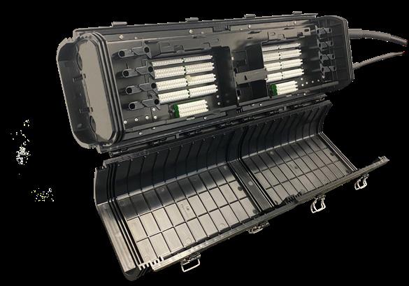

• Separate secure splice chamber, provides protection and security of incoming and outgoing fibers Access
• Four individual secure compartments (2 each - front and rear), separate splices from the drop ports, providing network security
• Hinged front covers allows easy access for installation and network maintenance
• 4 cable entrance/exit ports – 2 on each end
• Factory terminated single 288 cable allows provider to determine assignment of individual feeder and distribution ports
• Factory installed fiber tail, available in multiple lengths
• Will accept up to 9 individual compact ruggedized splitter modules
• Designation card included
StreetSmart ®
Aerial FDH - 288
• Customer defined configurations - provides maximum scalability across multiple services classes
• “Grow-as-you-go” capabilities
• Pre-terminated factory polished pigtail assembly - ensures improved network operability when spliced onto the feeder cable
Technical Specifications
StreetSmart Aerial FDH - 288
Dimensions
Material Black UV Resistant Thermoplastic
Weight Approx. 30 lbs.
Feeder/Express Ports 24-48 ports
Distribution Ports 144-288 ports
Cable Entrances 4 – 2 on the left, 2 on the right (Cables can exit on one side only)
Mounting Options Aerial or Strand Mount
Splitter Slots for WaveSmart Ruggedized Splitters 9 Part Number KK1-GAA - Ruggedized Compact Splitter Module, One 1x32 Splitter, LC/APC Front Pigtail Input(s) and Outputs, Bend Insensitive Fiber, 1.2mm Legs, 125 x 58.4 x 10 mm
Connector Types LC/APC, LC/UPC
Cable Types 144/288 OSP fiber Ribbon Outdoor (Non-Rated)
Factory Terminated Fiber
Tails 48 Fiber Feeder and 288 Fiber Distribution Available from 100 to 500 Foot Lengths
Staging Plates
Staging plate 021572, comes with splitter module. Capacity 2 staging plates - will accept up to 72 unused splitter legs
Splice Trays 5 Trays, 72 Per Tray - 360 Max. Capacity
Configured Part Numbers
Disclaimer/Note: Paper configurator shown is for reference only and should not be used to configure a saleable product configuration. All options shown on paper configurators may not be available or compatible with other options listed. Please contact your Clearfield representative for assistance in product configurations.
StreetSmart ®
Aerial FDH - 288
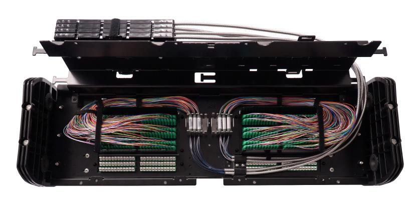
Ruggedized Splitter Module: Part number - KK1-GAA
Ruggedized Compact Splitter Module, One 1x32 Splitter, LC/APC Front Pigtail Input(s) and Outputs, Bend Insensitive Fiber, 1.2mm OSP Yellow Jacket, 125 x 58.4 x 10 mm, includes staging plate - 021572
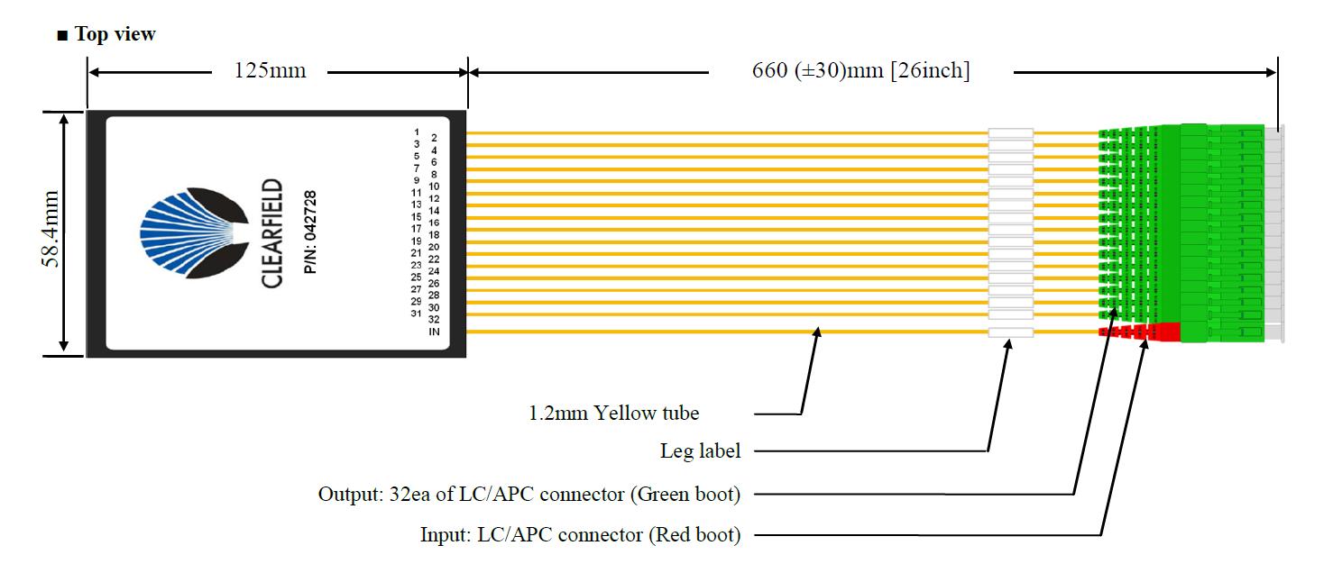
CraftSmart®
FiberFirst Pedestal
Application
The CraftSmart ® FiberFirst Pedestal provides a secure, above-ground access point for fiber-tothe-home (FTTH) networks. The internal components of the pedestal are optimized for fiber-only deployments and offer configuration flexibility to suit the needs of the network. The unique “open canvas” design provides mounting options for a wide range of Clearfield ® products, supporting PON and splice only applications and YOURx ® and MPT access terminals. The unique interlocking cover is designed to be free breathing to minimize condensation and allow any internal moisture to dissipate.
Description
Clearfield’s CraftSmart product line provides physical fiber protection for delivering a turn-key passive solution from the central office/headend to the customer premises. The CraftSmart FiberFirst Pedestal provides the most cost-effective non-metallic enclosure in the industry - meeting and exceeding the industry standards for strength, reliability and environmental concerns.
Designed and tested to withstand the harshest of environmental conditions, including UV, chemical and impact resistance, the FiberFirst Pedestal consists of a base and 2-part interlocking removable cover measuring 14”W x 12”D x 30”H. The rear wall of the cover includes built in multi-use backplane for mounting various products inside of the pedestal. Two industry standard telco security screws (216) are used to attach and lock the cover to the base. The base of the pedestal includes a built-in feature that allows the customer to add a ground stake to the pedestal.
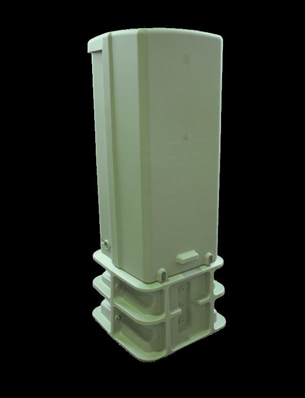
The FiberFirst Pedestal is designed for maximum flexibility and can be deployed in multiple applications. One pedestal for all applications, eliminating the need for multiple pedestals and reducing the SKU’s, allowing the customer to reduce costs.
PON Option
The CraftSmart FiberFirst Pedestal PON option provides a cost effective solution to service up to 144 homes. Each pedestal can be loaded with a single 12-fiber Clearfield feeder cassette and up to twelve cassettes for distribution ports. Splitter compartments give the flexibility to use up to five WaveSmart ® Ruggedized or High Density style splitters. The PON pedestal option is ideal for applications where a larger PON cabinet is not desired or cost-effective.
The PON option is available fully loaded with conventional feeder and distribution cable stubs or with Clearfield’s FastPass ® approach utilizing in-cassette splicing. The FastPass approach significantly reduces installation times allowing for double the number of fiber homes passed in the same amount of time versus conventional cable stub options. The PON option pedestal is also available empty to be used where cassettes are ordered separately to scale to meet a network’s evolving requirements.
Splice Only Option
The CraftSmart FiberFirst Pedestal Splice Only option incorporates field–tested slack management for incoming and outgoing fiber cables and includes craft friendly universal splice trays. Each splice tray supports 12 individual fusion splices or a single mass fusion splice. Up to 12 splice trays can be installed per pedestal. The splice only pedestal option supports drop cable scenarios or mid-span and ring-cut functionality. A ground bar is included for securing armored style cables and toneable drops.
Access Terminal Option
The CraftSmart FiberFirst Pedestal Access Terminal Option is available to support the deployment of all Clearfield Access Terminals. A cable management and mounting bracket kit is available for both the YOURx and MPT (Multi-Purpose) style terminals. These kits are easily installed in the field into an empty FiberFirst Pedestal which is ordered separately.

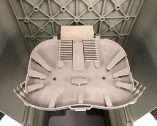

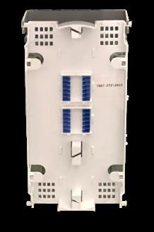
Splice Option
PON Option
004834
CraftSmart®
FiberFirst Pedestal
Features and Benefits
Integrity
• Constructed of durable, UV resistant material for maximum security and service life
• Two part system – 2-part bolt together base and interlocking 2-part pedestal covers, all made with a high impact resistant Thermoplastic Material
• Designed to meet and exceed GR-13, the unique interlocking cover is designed to be free breathing to minimize condensation and allow any internal moisture to dissipate
Protection
• Two-part interlocking cover provides protection from the elements.
• Two industry standard telco security screws (216) attach cover to base
• Direct bury base provides a uniform and secure installation while reducing the chances of leaning or tilting
Access
• Removable front cover provides complete access to inside of pedestal
• Built in multi-use backplane integrated into rear cover provides multiple mounting options for a wide variety of equipment
Investment
• High strength rigid construction ensures long term reliability in the harshest environments
• Multi-use pedestal can be used and deployed in multiple applications, eliminating the need for multiple specialty pedestals and reducing SKU’s
Technical Specifications
CraftSmart®
FiberFirst Pedestal
PON Option
Port Density Up to 144
Feeder/Express Ports 12
Cassettes Types Supported Clearview Blue - Right Exit
Connector Types
Cable Types
Splice Capacity
Splitter Slots
SC/UPC, SC/APC, LC/UPC, LC/APC
Indoor/Outdoor, Outdoor (Non-Rated), Outdoor Armored (Non-Rated)
12 splices in each Clearview Cassette for in-cassette splice option
5 - Accepts either Clearfield’s WaveSmart Ruggedized or HD Splitter Weight
Configured Part Number
Disclaimer/Note: Paper configurator shown is for reference only and should not be used to configure a saleable product configuration. All options shown on paper configurators may not be available or compatible with other options listed. Please contact your Clearfield representative for assistance in product configurations.
J
1 Select Pedestal Type
A = Splice Only
B = Patch Only
C = Patch and Splice (In-cassette Splicing)
2
Select Feeder
A = 12 Ports (1 Cassette)
Z = 0 Feeders (Also Default for Splice Only)
3 Select # of Distribution Splices or
=
ZZZ = N/A
6 Select Cable Construction 6
4 Select Connector
A = SC/UPC F = LC/UPC
C = SC/APC H = LC/APC
Z = N/A
5
Select Mode / Type
1 = Singlemode - non-ribbon
2 = Singlemode – ribbon
Z = None
B = OSP Riser
E = OSP Non-Rated
F = 900µm TB (FieldSmart Patch and Splice)
M = Armored OSP Non-Rated
Z = N/A
XXXM or XXXF
XXXM = Length of Pigtail in Meters
XXXF = Length of Pigtail in Feet
* Not all configurations are visible. Ask your Clearfield Sales Representative for additional ordering options.
Clearfield Vault Option Pre-Configured Part Number - Must Be Ordered Separately
VC7B-CZP Vault, Below Grade Clearfield, Split HDPE Lid, with Cut Out for FieldSmart Cabinets and Pedestal, Flared Wall, with Bolt Kit
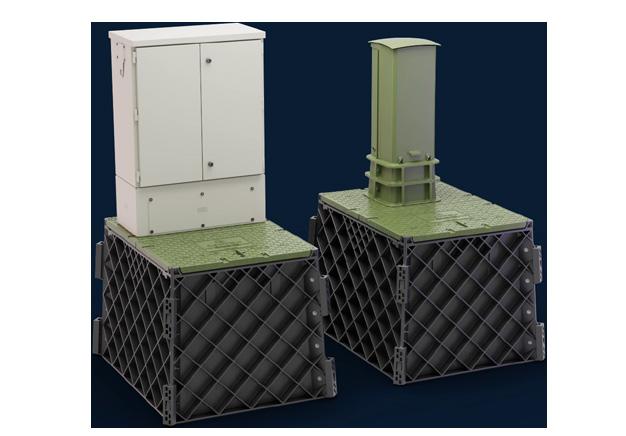
CraftSmart® FiberFirst Pedestal
Terminal Bracket Pre-Configured Part Numbers
Part Number Description
CFP-121230 Pedestal, CraftSmart FiberFirst, Empty
CFP-121230-YOURX Kit, FiberFirst Pedestal, 12 x 12 x 30” Telco Green with YOURx Bottom Mount Bracket and Hardware
CFP-121230-MPT Kit, FiberFirst Pedestal, 12 x 12 x 30” Telco Green with MPT Bracket and Hardware
CFP-121230SEECHANGE Kit, FiberFirst Pedestal, 12 x 12 x 30” Telco Green with SeeChange/YOURx Top Mount Bracket and Hardware

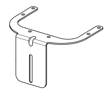
Pre-Configured Part Numbers - Splitter/Splice Options
Part Number Description
KC Series WaveSmart Ruggedized Splitters
KY Series WaveSmart Industry Standard Splitters
KE Series WaveSmart High Density Splitters
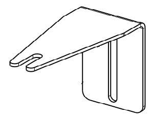
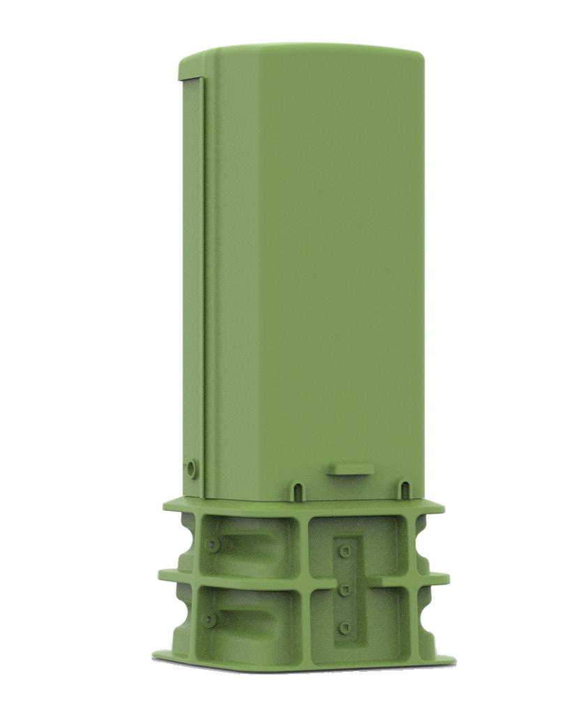
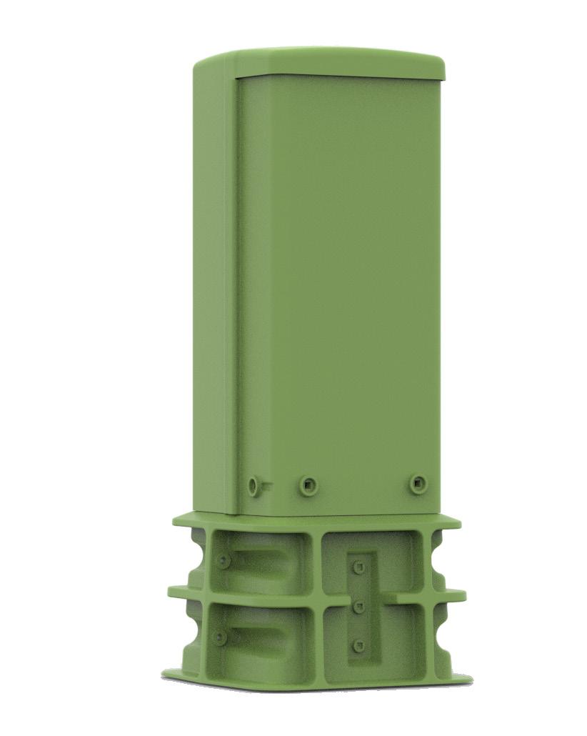
CraftSmart®
FiberFirst Pedestal

PON Insert Option
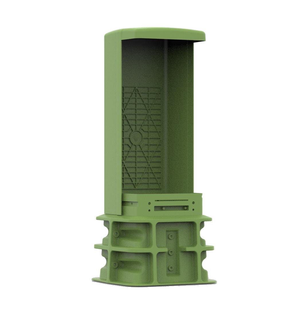
WaveSmart Splitters
HD Splitters
Feeder Cassette Slot
Distribution Cassette Slots 1-12
Splitter Staging
Rear Cover with Built-In Backplane
Inside Front Cover
CraftSmart®
FiberFirst 6-Inch Pedestal
Application
The CraftSmart ® FiberFirst 6-Inch Pedestal provides a secure, above-ground access point for fiberto- the-home (FTTH) networks. The internal components of the pedestal are optimized for fiber-only deployments and offer configuration flexibility to suit the needs of the network. The compact design is ideal for housing several Clearfield ® products.
Description
Clearfield’s CraftSmart product line provides physical fiber protection for delivering a turnkey passive solution from the central office/headend to the customer premises. The CraftSmart FiberFirst 6-Inch Pedestal provides a small, cost-effective, non-metallic enclosure - meeting the industry standards for strength, reliability and environmental concerns.
The FiberFirst 6-Inch Pedestal consists of a two-part base and removable cover measuring 5.9” in diameter and 20” or 30” in height and are designed and tested to withstand harsh environmental conditions, as well as UV, chemical and impact resistance. The pedestal includes a built-in, multi-use metal frame for mounting various products inside the pedestal. An industry standard telco security screw (216) is used to attach and lock the cover to the base.
The FiberFirst 6-Inch Pedestal is designed to provide a small, aesthetically pleasing footprint, while providing maximum flexibility. Current configuration options include:
Empty Ped Option
The empty ped option is ideal for housing various types of fiber terminations. The pre-installed pedestal frame and ground bar make this a great option for rapid field installations close to the home.
SeeChange
® Terminal Option
The SeeChange Terminal mounting bracket option is available to support the deployment of Clearfield’s uniquely small SeeChange Terminal. The bracket and terminal can easily be installed in the field and ordered separately.
Features and Benefits
Integrity
• Constructed of durable, UV resistant material for maximum security and service life.
• Separate, direct-bury base and removable cover, all made with a high impact resistant thermoplastic material.
• Designed to meet and exceed GR-13.
Protection
• Interlocking cover provides protection from the elements.
• Industry standard telco security screw (216) attaches cover securely to base.
• Direct-bury base provides a uniform and secure installation while reducing the chances of leaning or tilting.
Access
• Removable cover provides complete access to inside of pedestal.
• Built-in, integrated frame provides multiple mounting options for a wide variety of applications.
Investment
• High strength, rigid construction ensures long term reliability in the harshest environments.
• Small profile and cost-effective pedestal can be deployed in a variety of applications.
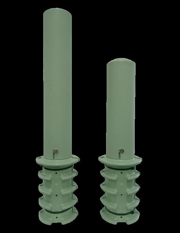


CraftSmart® FiberFirst 6-Inch Pedestal
Technical Specifications
CraftSmart FiberFirst 6-Inch Pedestal
Cover Only Dimensions 30” Ped - 5.9” Diameter x 31”H 20” Ped - 5.9” Diameter x 21” H
Base Only Dimensions 8.75” Diameter x 16.5”H (buried 12” deep with 4.5” above ground)
Cover Material High Impact Resistant Thermoplastic Material
Base Material High Impact Resistant Thermoplastic Material
Mounting Options Direct Buried
Security/Locking Telco Security (216) Screw Locks Cover to Base
Ground Bar Included With Each Pedestal
Ground Stake Ground Stake location molded into base. Customer supplied ground stake.
Application Tether Bracket Weight 10 lbs.
Pre-Configured Part Numbers
Part Number Description
CFP-0630-EMPTY-SUB FiberFirst 6” Diameter Fiber Pedestal, Telco Green 30” H
CFP-0630-SEECHANGE BRACKET KIT Kit, SeeChange Bracket for 6” FiberFirst Pedestal (Bracket Kit Only, Does Not Include Pedestal)
CFP-0620-EMPTY-SUB FiberFirst 6” Diameter Fiber Pedestal, Telco Green 20” H 023283 Bracket, Fiber Tether Support Assembly for Clearfield 6” Pedestal (Does Not Include Pedestal) 023597 Kit, 30” FiberFirst Pedestal and 023283 Tether Bracket (Unassembled in Pedestal)
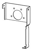
023283 - Tether Bracket
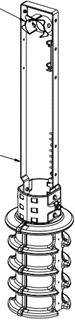
023597 – Kit (Shown assembled in 30” Ped)
CraftSmart®
FiberFirst Metallic Pedestal
Application
The CraftSmart FiberFirst Metallic Pedestal provides splice or interconnect connectivity at the access point for the last mile drop.
Description
The CraftSmart FiberFirst Metallic Pedestal is an empty pedestal that allows customers to deploy in a wide variety of applications, including field-tested slack management and fiber splice trays to provide a craft-friendly splice only access solution. The CraftSmart FiberFirst Metallic Pedestal can be configured to support the specific drop cable, multi-fiber and ring cut requirements. The solid surface back plane makes it possible for customers to integrate multiple products inside the pedestals.
Features and Benefits
Integrity
• Designed to be a cost-effective fiber delivery point.
• Preconfigured drill points make it easy add fiber management, brackets and accessories.
• Made from 18 Gauge Galvanneal - with powder coat paint.
Protection
• Open architecture
• Strength, rigidity and security all in a high-performance powder coated galvanneal material.
• Designed to Telcordia GR-13 and RUS PE-91 specifications.
• Single point self-locking cover provides secure pedestal locking and eased craft access.
Access
• Easy lift-off one piece front cover allows complete access to interior of pedestal.
• Can wrench fasteners for securing/locking.
• Drill points included in backplane for Accessory mounting.
Investment
• Cost effective delivery point solution.
• Up to 12 splice trays with Clearfield regular drop cable assembly or industry standard HFOC
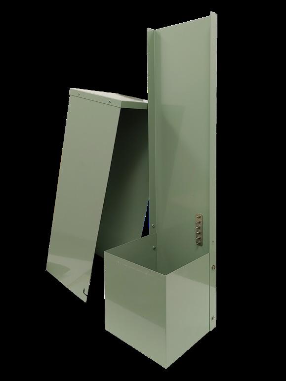
• Integrates distribution splices, splitters and slack cable for a cost-effective flexible option for any FTTX deployment.
CraftSmart® FiberFirst Metallic Pedestal
Technical Specifications
CraftSmart FiberFirst Metallic Pedestal
Dimensions
42.1” H x 10.3” W x 10.2” D (1098.55 mm x 266.70 mm x 266.70 mm)
Cover Height 31.25” (793.75 mm)
Base Height (Buried) 12” (304.80 mm)
Material Powder coated Galvanized steel
Density Up to 144 splices (288 with additional slice tray)
Number of Splice Trays Up to 12 (24 with additional splice tray bracket)
Splice Capacity 12 splices in each splice tray
Splice Tray Dimensions 10 mm H x 163 mm W x 126 mm D
Weight/Shipping 28 lbs. per ped - 16 per pallet
Pedestal and Accessories Ordered Separately
023232
Pedestal, FiberFirst Empty Metallic, Includes Drill Points and Ground Bar
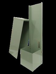
010005
004834
Pedestal Splice Kit (Shown with Multiple Splice Trays) Includes Splice Tray Bracket, Sacrificial Splice Tray, 2 Radius Rods and Mounting Hardware.
Tray, Splice, 12 Core Fiber Closure, Includes Splice Tray, 12 Splice Slots in Each Tray, Holds up to 12 Fibers. 10mm H x 163mm W x 126mm D
Access Terminal Brackets
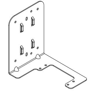

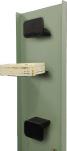

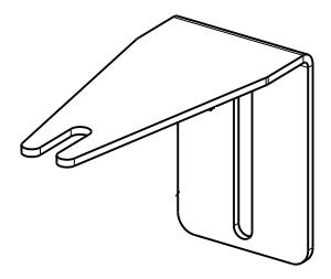
FieldSmart ® Fiber Delivery Point (FDP) Splice
Only Pedestal
Application
The FieldSmart FDP Splice Only Pedestal provides splice or interconnect connectivity at the access point for the last mile drop.
Description
The FieldSmart FDP Splice Only Pedestal incorporates field-tested slack management and fiber splice trays to provide a craft-friendly splice only access solution. The splice only pedestal can be configured to support the specific drop cable, multi-fiber and ring cut requirements. The Clearfield ® designed back plane makes it possible for the bulkheads to integrate into industry standard pedestals.
Features and Benefits
Integrity
• RUS listed
• Designed to comply to Telcordia GR-13 Protection
• Open architecture

• Strength, rigidity and security all in a high-performance thermo-plastic or metallic material designed to Telcordia GR-13 and RUS PE-91 specifications
• Single point self-locking cover provides secure pedestal locking and eased craft access
• Available in metallic and non-metallic pedestals
Access
• Removable front covers on metallic versions
• Can wrench fasteners
• Easy lift-off dome on thermo-plastic models - allows for 360° access permits complete access to all wire work and equipment Investment
• Low cost entry with RUS listed pedestal
• Utilizes cost effective
• Up to 16 splice trays with Clearfield regular drop cable assembly or industry standard HFOC
• Integrates distribution splices, splitters and slack cable for a cost-effective flexible option for any FTTP deployment
Accessories
• Splice Tray - Each splice-slot holds up to 2 fibers. 12 splice-slots in each tray hold up to 24 fibers. 10 mm H x 163 mm W x 126 mm D
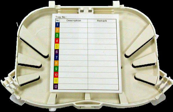
FieldSmart ® Fiber Delivery Point (FDP)
Splice Only Pedestal
Technical Specifications FieldSmart Splice Only Ped
Density Up to 144 splices
Number of Splice Trays Up to 16 Up to 6
Splice Capacity 24 splices in each splice tray
Splice Tray Dimensions 10 mm H x 163 mm W x 126 mm D
Configured Part Numbers
Disclaimer/Note: Paper configurator shown is for reference only and should not be used to configure a saleable product configuration. All options shown on paper configurators may not be available or compatible with other options listed. Please contact your Clearfield representative for assistance in product configurations.


1 Select Pedestal Type
2 = Emerson BD5
3 = Pencell 10 x 10
W = Proform non-metallic
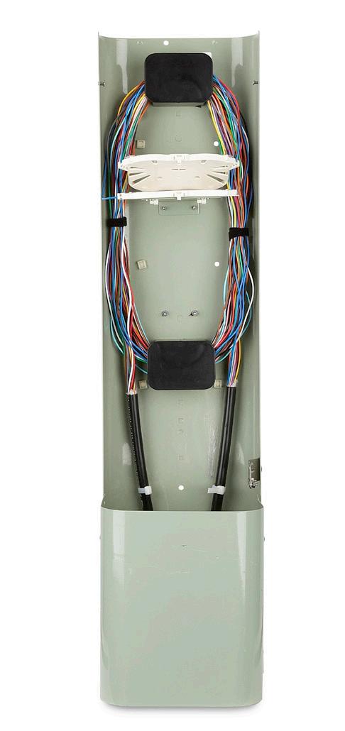
2 Select Distribution Port Count X X X = port count in increments of 12 up to 144 ports Z Z Z = N/A
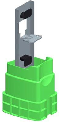

CraftSmart®
Fiber Protection Vaults (FPV)
Application
The CraftSmart Fiber Protection Vault (FPV) is a flat packed, easily assembled solution for the optimized installation and deployment of Clearfield FDH Cabinets and Pedestals.
All vaults include a custom cut-out in half of the lid, designed specifically for easy installation and mounting of FieldSmart FDH Cabinets and FieldSmart Fiber Delivery Point (FDP) Pedestals in above grade deployments with below grade slack cable storage. FPVs are equally suited for drop cable, splicing, interconnect and mid-span scenarios, which allows for maximum flexibility and customization in the outside plant network.
Designed to meet industry standards for strength and reliability exposure to underground applications.
Description
The Clearfield ® CraftSmart product line provides physical fiber protection for products. It completes and delivers a turn-key passive solution from the central office/headend to the customer premises. CraftSmart Fiber Protection Vaults (FPV) provide the most costeffective thermoplastic enclosures in the industry - meeting and exceeding the industry standards for strength, reliability, and environmental concerns.

Formed from a High-Density Polyethylene (HDPE) Thermoplastic, these vaults provide a solid base and light-weight material alternative to traditional polymer concrete enclosures. All CraftSmart Vaults come flat packed are easily assembled by the customer on site. The flat pack configuration allows for reduced transportation, handling, and storage costs typically associated with a pre-assembled vault. Multiple industry standard sizes can be ordered with solid covers or pre-cut covers to accommodate all FieldSmart passive and active cabinet solutions.
Features and Benefits
Integrity
• Designed to comply to Telcordia GR-902
• Compliant to ANSI/SCTE 77 2010 as specified by N.E.C. ANSI C57 Enclosure Integrity
• Compliant to Western Underground Guide 3.6
• Stainless steel hardware
Protection
• Hex head security bolts
• Vaults incorporate a unique overlapping cover design to reduce soil mitigation into box
Access
• Multiple cover options, including a 2-piece split thermoplastic cover, provide ease of access and cut outs for FieldSmart cabinets and pedestals
• Mounting bolts for FieldSmart cabinets and pedestals are included with cutout lid option
Investment
• High strength rigid construction ensures long term reliability in the harshest environments
• Lighter and easier to handle than concrete, which increases the overall safety factor
• Flat packed to improve efficiencies and lower cost of transportation, storage and deployment
CraftSmart®
Fiber Protection Vaults (FPV)

Split Thermoplastic Cover Cover with Cutout in ½ Lid
Application: Clearfield Passive Cabinets and Pedestals
Mounting: New cabinet and/or pedestal deployment
Static
Technical Specifications
lbs
Pre-Configured
Part Numbers

Application:
Clearfield FDH Cabinets, 144, 288, 432, 576, 1152 PON and 432, 864, 1728 XCONN. FiberFirst Pedestal, YOURxTerminal
Fiber Protection Vaults (FPV)
023726 Universal Cabinet/Pedestal Mounting Hardware Kit
VCZ-STEP Step Rack/Ladder Kit, includes 2 – 30” Ladder Racks, 2 -14” Steps and Mounting Hardware
022986 Vault, ½ Solid Lid
022987 Vault, ½ Lid with Cut Out for Clearfield Cabinets and Pedestals
• Cardboard shipping box is covered with a plastic wrap/bag.
• Up to 3 vault boxes shipped per pallet.
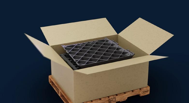

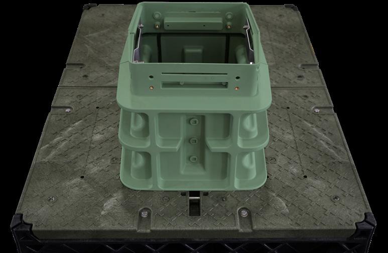
All FSC/FDH Cabinets Mounted on HDPE Lid
Any application where needed on any/all vaults
Can be used for VC7B-BCP (use two halves) or VC7B-CZP (use one of these and one of the lids with cut outs) to mount a Clearfield Cabinet or Pedestal; Spare or Replacement Lid
Use with ½ solid lid for VC7B-CZP; Spare or Replacement Lid
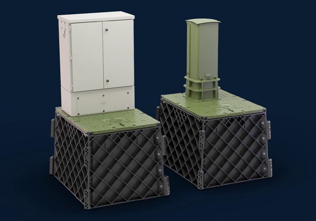
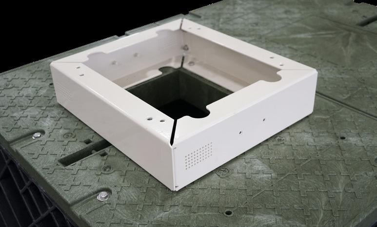
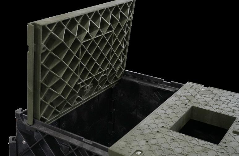
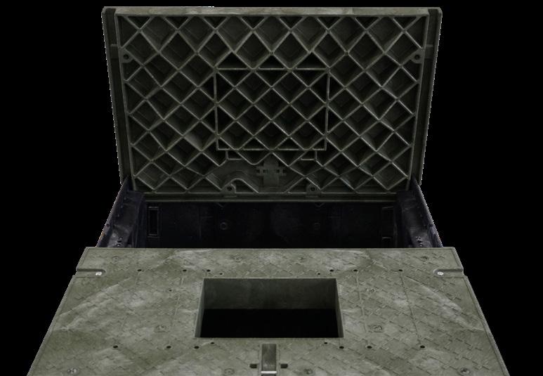
CraftSmart ® Fiber Protection Boxes (FPB)
Application
The CraftSmart Fiber Protection Boxes (FPB) provide a place for below grade cable slack storage and access in greenbelt and light pedestrian traffic applications.
Description
The CraftSmart Fiber Protection Boxes are part of a full line of above and below grade field enclosures. They provide full optimization of a fiber deployment when used alongside a Clearfield ® FieldSmart ® platform of inside plant panels, outside plant cabinets and wall boxes.
Boxes are designed to meet a broad range of fiber, coax and copper needs of the broadband, telecommunications and utilities industries. The FPBs provide a place for below grade cable slack storage and are a good fit for access in greenbelt areas, places that are undeveloped, wild or agricultural areas and similar locations where there is light pedestrian traffic, such as a sidewalk.

The CraftSmart Fiber Protection Box is available in five different sizes. Functioning as a stand-alone, the FPB provides below grade slack storage for fiber or other media. The body is formed with a High Density Polyethylene (HDPE) Thermoplastic and a solid Thermoplastic lid that ensures strength and stability of the product.
Features and Benefits
Integrity
• High-quality HDPE designed body distributes load evenly across sidewalls
• Solid Thermoplastic lid ensures strength and stability Protection
• Universal bolt security system
• All boxes incorporate a unique “T” style overlapping cover design to reduce soil mitigation into box Access
• Single piece solid thermoplastic cover provides ease of access into boxes
• All the plastic lids on these boxes are rated at light duty or greenbelt as listed with the SCTE77 specification: 5,000 lbs
Investment
• High strength rigid construction ensures long term reliability in the harshest environments
• Lighter and easier to handle than concrete, which increases the overall safety factor
Accessories
• Grounding option
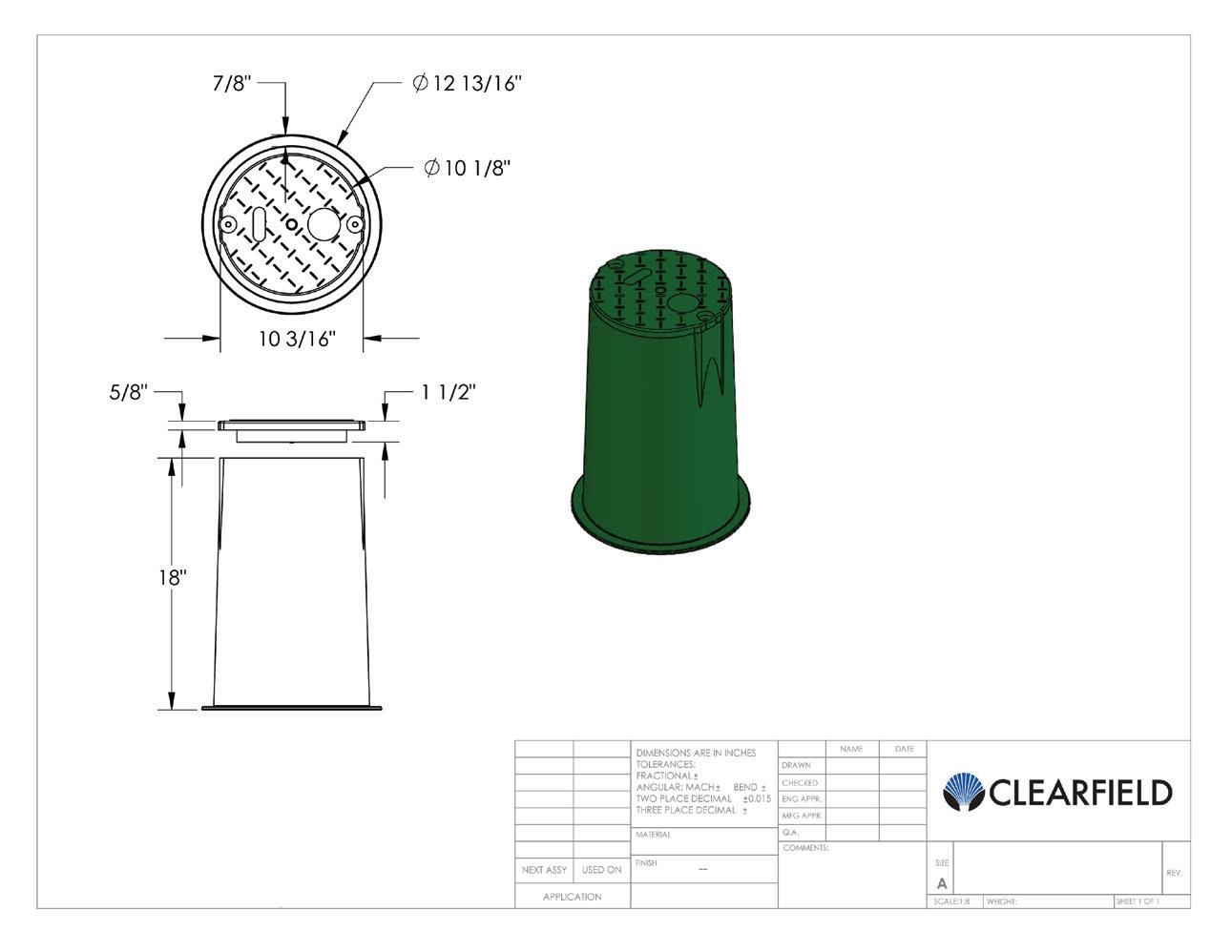
FST-GND-BAR-KIT: Kit, ground bar and mounting hardware for use in flowerpots and vaults. Includes ground bar, ground lug and
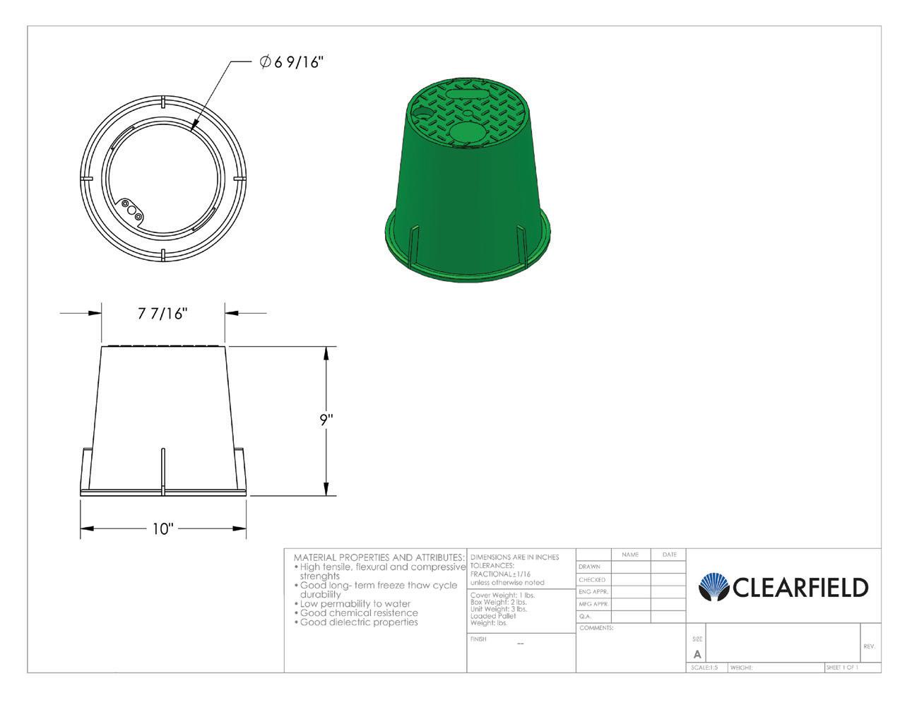


CraftSmart ® Fiber Protection Boxes (FPB)
Pre-Configured Part Numbers
FST-GND-BAR-KIT Kit, ground bar and mounting hardware for use in flowerpots and vaults. Includes ground bar, ground lug and mounting bolts.
FieldSmart ®
Cabinet and Vault Options
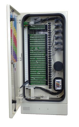
FieldSmart 144, 288 PON, 432 CrossConnect, 432 PON or Hub Collapse Cabinet
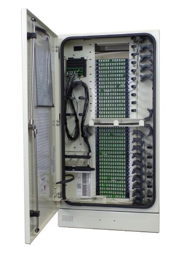
Part
VC7B-CZP
Vault, Below Grade Clearfield, Split HDPE Lid, with Cut Out for FieldSmart Cabinets, Flared Wall, with Bolt Kit
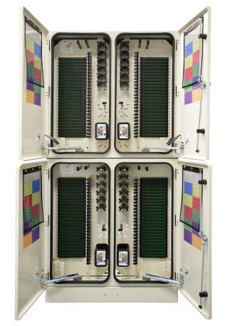
FieldSmart 1152 PON or 1728 CrossConnect Cabinet
VC7B-CZP
V9B-HZP-PC

Vault, Pencell 48 x 48 x 36”, Complete Split Polymer Concrete Lid, Cut Out for 864 Cabinet, Polymer Concrete Straight Wall
Vault, Below Grade Clearfield, Split HDPE Lid, with Cut Out for FieldSmart Cabinets, Flared Wall, with Bolt Kit
FieldSmart 576 PON or 864
Cross-Connect Cabinet

Vault, Below Grade Clearfield, Split HDPE Lid, with Cut Out for FieldSmart Cabinets, Flared Wall, with Bolt Kit
FieldSmart 864 Port PON FDH Cabinet
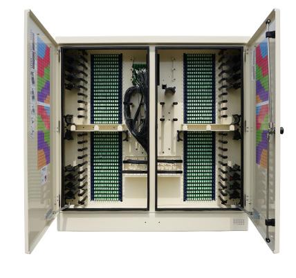
VC7B-CZP
Introduction to Access Products
Wall Boxes, Access Points and Terminals
Whether it’s a pedestal, a vault or a wall box, we have the fiber management products to round out the last mile or access point of your network. FieldSmart ® Fiber Delivery Point (FDP) products can be placed aerially in pole or strand-mount closures, in pedestals on the ground or below grade in small hand holes with closures that provide superior splicing or interconnect functionality.
The FieldSmart FDP Wall Box line has been optimized for both indoor and outdoor deployments. They are ideal for both business-class and residential environments. The OSP platform is designed for the harshest environment, supporting NEMA 4 performance requirements, while still allowing for conduit entry through field-deployed knock-outs on both the rear and bottom of the unit. Designed from conception to provide fast, easy fiber jumper routing and ease of access to all circuits, the FieldSmart FDP Wall Box system is craft-friendly, keeping the installer’s needs for quick deployment, intuitive use and ease of maintenance as our top priority.
With the Clearview ® Cassette at its heart, the FieldSmart FDP Wall Box gives service providers plug-and-play integration based upon the configuration requirements of the application. With a choice of up to 48 ports for the outdoor model or up to 144 ports for the indoor model, users can easily scale their networks using the same consistent Clearview Cassette deployment strategy.
The YOURx ® platform (TAP, wall box and terminals) ensures every provider has the freedom of choice to match drop cable technology with the needs of their environment and first-cost priorities. Designed around a single architecture—the YOURx FlexPort – YOURx is the only fiber delivery platform that eliminates the need for expensive proprietary connectors when deploying fiber in the distribution and drop portions of the network.


FieldSmart ® Fiber Delivery Point (FDP)
Outdoor 24-Port Wall Box
Application
The FieldSmart FDP 24 Port Outdoor Wall Box is ideal for both residential MDUs and business-class environments. Configurable for either patch only, patch and splice (Clearfield’s in-cassette splicing solution) or MPO plug-and-play, Outdoor Wall Boxes supports all cable scenarios for the outside plant. The OSP platform is designed for the harshest environments, supporting NEMA 4 performance requirements, while providing conduit entry through field-deployed knock-outs on both the rear and bottom of the unit. Additional applications include, fiber demarcations, entrance facilities and security systems (CCTV).
Description
Designed from conception to provide fast and easy fiber jumper routing with ease of access to all circuits, the FieldSmart FDP Outdoor 24 Port Wall Box is craft-friendly, keeping the installer’s needs for quick deployment, intuitive use and ease of maintenance as the top priorities. Utilizing the Clearview ® Cassette, the boxes easily scale from 12 to 24 ports with the industry standard adapter of choice. Ring cut or mid-span capabilities allow distribution cables to be daisy-chained and for fiber hand-off through the riser, while a swinging bulkhead provides rear-access to cassettes and protects sub-unit slack storage. With lockable doors for added protection and a solid enclosure design to protect fiber terminations from damage, the FieldSmart Fiber Delivery Point (FDP) Wall Box product line provides superior fiber management for outdoor environments.
Features and Benefits
Integrity
• Terminations designed, tested and certified to Telcordia GR-326
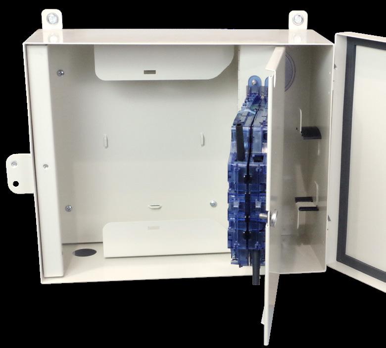
• Clearfield ® FiberDeep ® Guarantee: 0.2 dB insertion loss or less, exceeding industry standards
• Fiber cable certified to GR-20 and GR-409
• Supports all industry standard singlemode and multimode connectors
• 100% performance tested for insertion loss, return loss and final mechanical inspect Protection
• Designed to comply with NEMA 4 requirements
• Zinc-plated for harsh environment reliability
• Radius protected storage for up to three meters of jacketed fiber or patch cord slack is provided (patch side)
• Internal radius protected storage of up to one meter of 900 μm fiber and three meters of jacketed fiber (splice side)
• Rugged steel construction with locking access doors provides security from tampering or inadvertent damage
• Integrated fiber management protects fiber from micro-bend and macro-bend damage
• Ability to padlock the outside door for increased security Access
• Ships ready to install with cable clamp kit, locks and miscellaneous accessories
• Multiple entry/exit points for feeder/customer premise cables
• Larger design facilitates ease of access in the environments the product is deployed
• Rear wall knockout for conduit entry
• Accessible using a standard can wrench Investment
• Scalable to 24 ports of fiber using Clearview ® Cassettes loaded with the interface of your choice
• Pre-configured and pre-loaded factory terminated assemblies
• Patch only or patch and splice configurations supported
• Boxes can be configured as a tie box and later converted to patch only or patch and splice, utilizing the Clearview Cassette
FieldSmart ® Fiber Delivery Point (FDP)
Outdoor 24-Port Wall Box
Technical Specifications
FieldSmart Outdoor 24-Port Wall Box
Dimensions
12.52” H x 16.22” W x 5.75” D (318.01 mm x 411.98 mm x 146.05 mm)
Port Density Up to 24 ports
Cassette Types Supported Clearview ® Blue
Connector Types
Cable Types
SC/UPC, SC/APC, LC/UPC, LC/APC, MPO
Indoor/Outdoor, Outdoor (Riser/Non-Rated), Outdoor Armored (Riser/Non-Rated)
Splice Capacity 12 or 24 splice configurations in each Clearview Cassette
Storage Capacity One meter of 900 μm fiber and up to 20 feet (6.10 m) buffer tube
Material 16 gauge cold rolled steel (zinc chromate with almond powder coating)
Configured Part Numbers
Disclaimer/Note: Paper configurator shown is for reference only and should not be used to configure a saleable product configuration. All options shown on paper configurators may not be available or compatible with other options listed. Please contact your Clearfield representative for assistance in product configurations.
1 Select Wall Mount Style
C = Patch only
D = Patch and splice
H = Tie panel
2 Select Clearview Cassette
B = Clearview Blue
Accessories
• Pole Mount Kit (FMA-H4Z-SUB)
Select Connector Style
A = SC/UPC
C = SC/APC
F = LC/UPC
H = LC/APC
Select Cable Construction
B = OSP riser rated
E = OSP (non-rated)
F = Patch and splice (loose tube)
M = OSP (armored, non-rated)
Z = Patch and splice ribbon
Select Mode / Type Select Cable Exit *
1 = Singlemode, non ribbon
2 = Singlemode, ribbon
3 = Multimode (62.5)
9 = No fiber – multimode
0 = No fiber - singlemode
4 = Bottom left
Z = None or patch and splice (ribbon)
XXXM or XXXF
XXXM = Length in meters
XXXF = Length in feet
* Cable exit is defined by which direction the cable exits the panel when viewing it from the front.

• FieldSmart Outdoor Wall Box Accessory Kit (FMA-XXX-36) FMA-XXX-36 FMA-H4Z-SUB
FieldSmart ® Fiber Delivery Point (FDP)
Outdoor 48-Port Wall Box
Application
The FieldSmart FDP 48 Port Outdoor Wall Box is ideal for both residential MDUs and business-class environments. Configurable for either patch only, patch and splice (Clearfield’s in-cassette splicing solution) or MPO plug-and-play, Outdoor Wall Boxes supports all cable scenarios for the outside plant. The OSP platform is designed for the harshest environments, supporting NEMA 4 performance requirements, while providing conduit entry through field-deployed knock-outs on both the rear and bottom of the unit. Additional applications include, fiber demarcations, entrance facilities and security systems (CCTV).
Description
Designed from conception to provide fast and easy fiber jumper routing with ease of access to all circuits, the FieldSmart FDP Outdoor 48 Port Wall Box is craft-friendly, keeping the installer’s needs for quick deployment, intuitive use and ease of maintenance as the top priorities. Utilizing the Clearview ® Cassette, the box easily scale from 12 to 48 ports with the industry standard adapter of choice. Ring cut or mid-span capabilities allow distribution cables to be daisy-chained and for fiber hand-off through the riser, while a swinging bulkhead provides rear-access to cassettes and protects sub-unit slack storage. With lockable doors for added protection and a solid enclosure design to protect fiber terminations from damage, the FieldSmart Fiber Delivery Point (FDP) Wall Box product line provides superior fiber management for outdoor environments.
Features and Benefits
Integrity
• Terminations designed, tested and certified to Telcordia GR-326
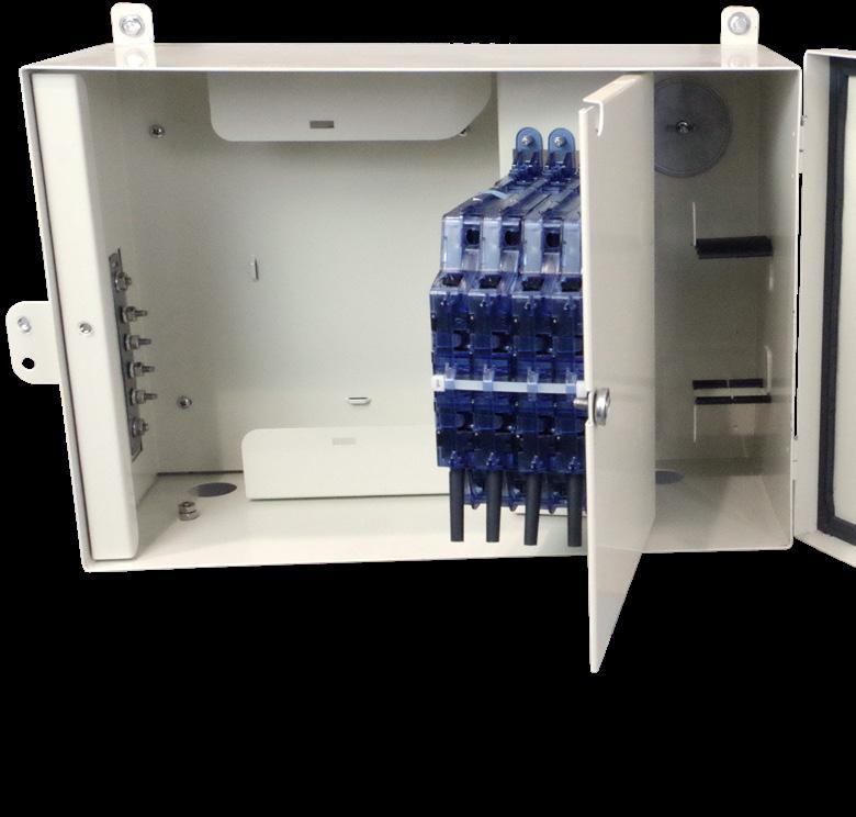
• Clearfield ® FiberDeep ® Guarantee: 0.2 dB insertion loss or less, exceeding industry standards
• Fiber cable certified to Telcordia GR-20 and GR-409
• Supports all industry standard singlemode and multimode connectors
• 100% performance tested for insertion loss, return loss and final mechanical inspect Protection
• Outdoor unit designed to comply with NEMA 4 requirements
• Zinc-plated for harsh environment reliability
• Radius protected storage for up to three meters of jacketed fiber or patch cord slack is provided (patch side)
• Internal radius protected storage of up to one meter of 900 μm fiber and three meters of jacketed fiber (splice side)
• Rugged steel construction with locking access doors provides security from tampering or inadvertent damage
• Integrated fiber management protects fiber from micro-bend and macro-bend damage
• Ability to padlock the outside door for increased security Access
• Removable doors and non-angled connectors enable fast, easy fiber jumper routing
• Ships ready to install with cable clamp kit, locks and miscellaneous accessories
• Multiple entry/exit points for feeder/customer premise cables
• Larger design facilitates ease of access in the environments the product is deployed
• Rear wall knockout for conduit entry
• Accessible using a standard can wrench Investment
• Scalable to 48 ports of fiber using Clearview Cassettes loaded with the interface of your choice
• Pre-configured/pre-loaded factory terminated assemblies
• Patch only or patch and splice configurations supported
• Box can be configured as a tie box and later converted to patch only or patch and splice, utilizing the Clearview Cassette
FieldSmart ® Fiber Delivery Point (FDP)
Outdoor 48-Port Wall Box
Technical Specifications
FieldSmart Outdoor 48 Port Wall Box
Dimensions 12.52” H x 18.92” W x 7.26” D (318.01 mm x 480.56 x 184.40 mm)
Port Density Up to 48 ports
Cassette Types Supported Clearview ® Blue
Connector Types
Cable Types
SC/UPC, SC/APC, LC/UPC, LC/APC, MPO
Indoor/Outdoor, Outdoor (Riser/Non-Rated), Outdoor Armored (Riser/Non-Rated)
Splice Capacity 12 or 24 splice configurations in each Clearview Cassette
Storage Capacity One meter of 900 μm fiber and up to 3 meters of jacketed fiber Material 16 gauge cold rolled steel (zinc chromate with almond powder coating)
Configured Part Numbers
Disclaimer/Note: Paper configurator shown is for reference only and should not be used to configure a saleable product configuration. All options shown on paper configurators may not be available or compatible with other options listed. Please contact your Clearfield representative for assistance in product configurations.
A = SC/UPC
C = SC/APC
F = LC/UPC
H = LC/APC
2 Select Clearview Cassette
B = Clearview Blue
Accessories
• Pole Mount Kit (FMA-H4Z-SUB)
5 Select Mode / Type
1 = Singlemode, non ribbon
2 = Singlemode, ribbon
3 = Multimode (62.5)
9 = No fiber – multimode
0 = No fiber - singlemode
• FieldSmart Outdoor Wall Box Accessory Kit (FMA-XXX-36)
Select Cable Construction
B = OSP riser rated
E = OSP (non-rated)
F = Patch and splice (loose tube)
M = OSP (armored, non-rated)
Z = Patch and splice ribbon
7
Select Cable Exit *
4 = Bottom left
Z = None or patch and splice (ribbon)
XXXM or XXXF
XXXM = Length in meters
XXXF = Length in feet
FieldSmart ® Fiber Delivery Point (FDP)
Indoor 36-Port Wall Box
Application
The FieldSmart Fiber Delivery Point (FDP) 36 Port Indoor Wall Box has been optimized for MDU (Multi Dwelling Unit) applications. With the Clearview ® Cassette at its heart, the FieldSmart FDP Wall Box gives service providers plug-and-play integration based upon the configuration requirements of the application. With the ability to house a single 1 x 32 splitter, indoor wall boxes are perfect for the deployment of PON-based FTTH networks in an MDU environment. Additional applications include, fiber demarcations, entrance facilities and security systems (CCTV).
Description
The FieldSmart Fiber Delivery Point (FDP) 36 Port Indoor Wall Box easily allows the user to scale from 12 to 36 ports. Utilizing Clearview Cassettes, the product is shipped loaded with the industry standard adapter of choice and can be configured for patch only, patch and splice (Clearfield’s in-cassette splicing solution) and MPO plug-and-play applications, while supporting all cable constructions for the inside plant. It is ring cut or mid-span capable, allowing for the distribution cables to be daisy-chained and for fiber hand-off through the riser. The box has a fixed bulkhead with rear-access to the cassettes and sub-unit slack storage, security enabled doors for extra protection and a solid enclosure to protect fiber terminations from damage. Designed from conception to provide fast, easy fiber jumper routing and ease of access to all circuits, the Wall Box system is craft-friendly, keeping the installer’s needs for quick deployment, intuitive use and ease of maintenance as the top priority.
Features and Benefits
Integrity
• Terminations designed, tested and certified to Telcordia GR-326
• Clearfield ® FiberDeep ® Guarantee: 0.2 dB insertion loss or less, exceeding industry standards
• Fiber cable certified to Telcordia GR-20 & GR-409
• Supports all industry standard singlemode and multimode connectors
• 100% performance tested for insertion loss, return loss and final mechanical inspect
Protection
• Radius protected storage for up to five meters of jacketed fiber or patch cord slack is provided (patch side)
• Rugged steel construction with security enabled doors provide protection from tampering damage
• Integrated fiber management protects fiber from micro-bend and macro-bend damage
• A grounding lug is included
Access
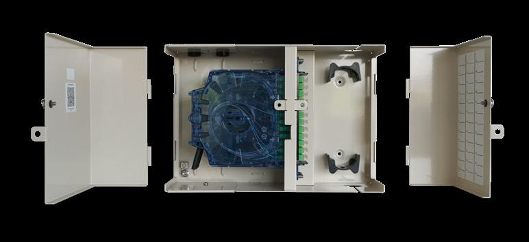
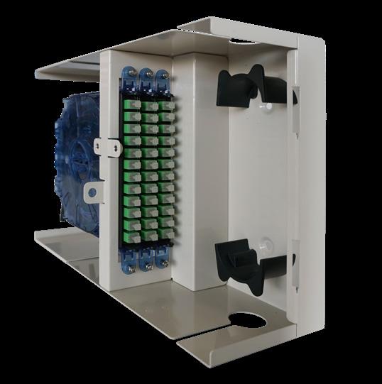
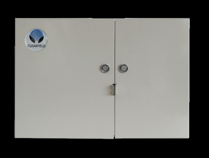
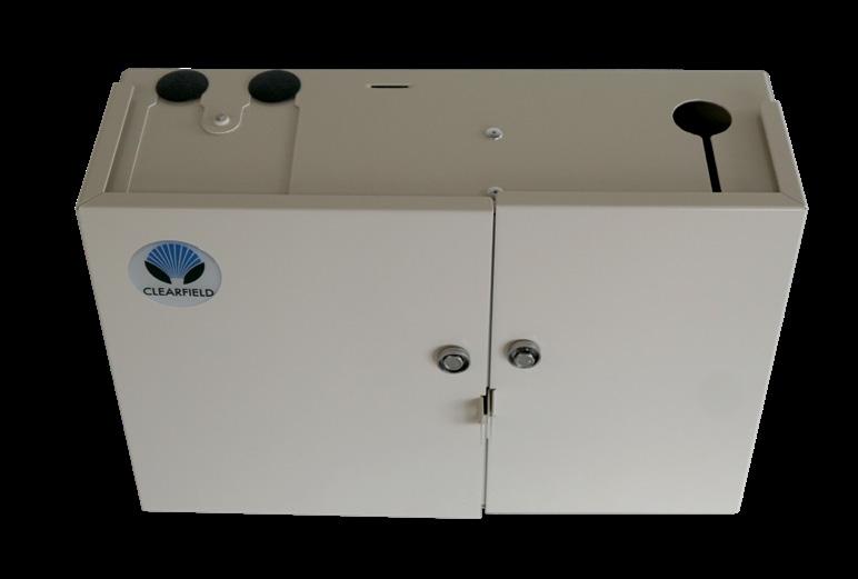
• Removable doors and non-angled connectors enable fast, easy fiber jumper routing, reducing the risk of fiber damage when cleaning or patching fibers
• Ships ready to install with miscellaneous accessories
• Upper and lower entry/exit points for feeder/customer premise cables
• Larger design facilitates ease of access in the environments product is deployed
• Accessible using a standard can wrench
• Pre-loaded for patch and splice or patch only applications
Investment
• Scalable to 36 ports of fiber using Clearview Cassettes loaded with the interface of your choice
• Pre-configured/pre-loaded factory terminated assemblies
• Box can be configured as a tie box and later converted to patch only or patch and splice, utilizing the Clearview Cassette
FieldSmart ® Fiber Delivery Point (FDP)
Indoor 36-Port Wall Box
Technical Specifications
FieldSmart Indoor 36-Port Wall Box
Dimensions 10.34” H x 15.00” W x 5.20” D (262.63 mm x 381 mm x 132.08 mm)
Port Density Up to 36 ports
Cassette Types Supported Clearview ® Blue
Connector Types
Cable Types
Splice Capacity
Storage Capacity
SC/UPC, SC/APC, LC/UPC, LC/APC, MPO
Indoor Riser, Indoor Plenum, Indoor/Outdoor
12 or 24 splice configurations in each Clearview Cassette
One meter of 900 μm fiber and up to 5 meters of jacketed fiber
Material 18 gauge cold rolled steel (almond powder coating)
Configured Part Numbers
Disclaimer/Note: Paper configurator shown is for reference only and should not be used to configure a saleable product configuration. All options shown on paper configurators may not be available or compatible with other options listed. Please contact your Clearfield representative for assistance in product configurations.
1 Select Wall Box Style
E = Patch only
F = Patch and splice
G = Tie panel
2 Select Clearview Cassette B = Clearview Blue
3 4 Select Port Count
012 = 12 port
024 = 24 port
036 = 36 port
Select Connector Style
= SC/UPC
= SC/APC
= LC/UPC
= LC/APC Select Cable Construction
A = Indoor riser rated (IFC)
B = OSP riser rated
C = Indoor, plenum rated (IFC)
E = OSP (non-rated)
M = OSP (armored, non-rated)
F = Patch and splice (loose tube)
Z = Patch and splice (ribbon)
1 = Singlemode, non ribbon 2 = Singlemode, ribbon 3 = Multimode (62.5) 9
FieldSmart ® Fiber Delivery Point (FDP)
Indoor 96-Port PON Wall Box
Application
The FieldSmart Fiber Delivery Point (FDP) 96-Port PON Indoor Wall Box has been optimized for MDU applications. Configurable with up to 96 distributed ports and 12 feeder ports, users can easily scale their networks using the same consistent Clearview ® Cassette deployment strategy. With the ability to house up to three 1 x 32 splitters, the Indoor Wall Box supports PON applications, as well as fiber demarcations, entrance facilities and security systems (CCTV).
Description
In the middle of the FieldSmart Fiber Delivery Point (FDP) Indoor Wall Box line is the 96 Port, which allows the user to easily scale 12 to 96 distributed ports. Designed from conception to provide fast and easy fiber jumper routing with ease of access to all circuits, the FieldSmart FDP Wall Box system is craft-friendly, keeping the installer’s needs for quick deployment, intuitive use and ease of maintenance as the top priorities. Utilizing Clearview Cassettes, the product is shipped loaded with the industry standard adapter of choice and can be configured for patch only, patch and splice (Clearfield’s in-cassette splicing solution) and MPO plug-and-play applications, while supporting all cable constructions for the inside plant. It is ring cut or mid-span capable, allowing for the distribution cables to be daisy-chained and for fiber hand-off through the riser. The box has a swinging bulkhead for rear-access to the cassettes and protects sub-unit slack storage, security enabled doors for extra protection and a solid enclosure to protect fiber terminations from damage.
Features and Benefits
Integrity
• Terminations designed, tested and certified to Telcordia GR-326
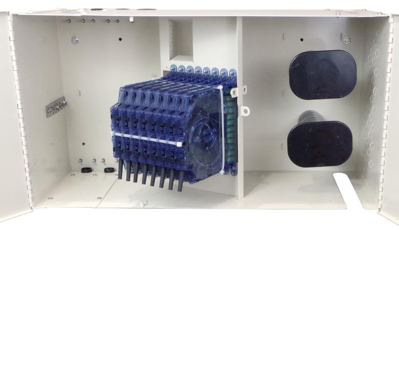
• Clearfield ® FiberDeep ® Guarantee: 0.2 dB insertion loss or less, exceeding industry standards
• Fiber cable certified to Telcordia GR-20 and GR-409
• Supports all industry standard singlemode and multimode connectors
• 100% performance tested for insertion loss, return loss and final mechanical inspect Protection
• Radius protected storage for up to five meters of jacketed fiber or patch cord slack is provided (patch side)
• Rugged steel construction with security enabled doors provide protection from tampering or inadvertent damage with industry standard can wrench fasteners
• Integrated fiber management protects fiber from micro-bend and macro-bend damage
• A grounding lug is included
Access
• Removable doors and non-angled connectors enable fast, easy fiber jumper routing, reducing the risk of fiber damage when cleaning or patching fibers
• Ships ready to install with cable clamp kit and miscellaneous accessories
• Upper and lower entry/exit points for feeder/customer premise cables
• Larger design facilitates ease of access in the environments product is deployed and is accessible using a standard can wrench
• Pre-loaded for patch and splice or patch only applications
Investment
• Scalable to 96 distributed ports and 12 feeder ports of fiber using Clearview Cassettes loaded with the interface of your choice
• Pre-configured/pre-loaded factory terminated assemblies
• Box can be configured as a tie box and later converted to patch only or patch and splice, utilizing the Clearview Cassette
FieldSmart ® Fiber Delivery Point (FDP)
Indoor 96-Port PON
Wall Box
Technical Specifications
FieldSmart Indoor 96-Port PON Wall Box
Dimensions 14.97” H x 27.31” W x 10.78” D (380.24 mm x 693.67 mm x 273.81 mm)
Port Density Up to 96 distributed ports and 12 feeder ports
Cassette Types Supported Clearview ® Blue
Connector Types
Cable Types
SC/UPC, SC/APC, LC/UPC, LC/APC, MPO
Indoor Riser, Indoor Plenum, Indoor/Outdoor
Splice Capacity 12 or 24 splice configurations in each Clearview Cassette
Storage Capacity
One meter of 900 μm fiber and up to 5 meters of jacketed fiber
Material 18 gauge cold rolled steel (almond powder coating)
Configured Part Numbers
Disclaimer/Note: Paper configurator shown is for reference only and should not be used to configure a saleable product configuration. All options shown on paper configurators may not be available or compatible with other options listed. Please contact your Clearfield representative for assistance in product configurations.
1 Select Wall Panel Style
M = Patch only
N = Patch and Splice
P = Tie panel
2 4 Select Clearview Cassette
B = Clearview Blue
3 Select Port Count
X X X = port count in increments of 12 2
Select Connector Style A = SC/UPC C = SC/APC F = LC/UPC H = LC/APC
5 Select Mode / Type
1 = Singlemode, non ribbon
2 = Singlemode, ribbon
3 = Multimode (62.5)
9 = No fiber – multimode
0 = No fiber - singlemode
Select Cable Construction
A = Indoor riser rated (IFC)
B = OSP riser rated
C = Indoor, plenum rated (IFC)
E = OSP (non-rated)
F = Patch and splice (loose tube)
M = OSP (non-rated armored)
Z = None or patch and splice (ribbon)
Select Cable Exit *
2 = Top left
4 = Bottom left
Z = N/A – use for patch and splice
XXXM or XXXF Accessories
• Ruggedized Splitter
• Dust Cover Plates (016023) - plate kit includes two plates and eight screws
XXXM = Length in meters
XXXF = Length in feet
* Cable exit is defined by which direction the cable exits the panel when viewing it from the front.
• Plate Kit (016023-01) - plate kit includes two plates, eight screws and eight rubber hole plugs
016023 016023-01
FieldSmart ® Fiber Delivery Point (FDP)
Indoor 144-Port Wall Box
Application
The 144 Port Indoor Wall Box has been optimized for MDU applications. With the Clearview ® Cassette at its heart, the FieldSmart FDP 144 Port Wall Box gives service providers plug-and-play integration based upon the configuration requirements of their application. Starting from 12 ports, users can easily scale their networks using the same consistent Clearview Cassette deployment strategy. With a compact 24” x 26” x 8” (609.60 mm x 660.40 mm x 203.20 mm) footprint, this wall box is perfect for the deployment of FTTH networks in an MDU environment. With the ability to house up to six ruggedized splitters, the wall box supports PON applications, as well as fiber demarcations.
Description
The FieldSmart Fiber Delivery Point (FDP) 144 Port Indoor Wall Box is Clearview optimized, allowing the user to easily scale from 12 to 144 distributed ports and 24 feeder ports. Utilizing Clearview Cassettes, the product is shipped and loaded with the industry standard adapters. It is preloaded for patch only, patch and splice (Clearfield’s in-cassette splicing solution) and MPO plug-and-play applications and supports all cable constructions for the inside or outside plant. It is ring-cut or mid-span capable, allowing for the distribution cables to be daisy-chained and for fiber hand-off through the riser. The box has a swinging bulkhead for rear-access to the cassettes, security enabled doors for extra protection and a solid enclosure to protect fiber terminations from damage. Designed from conception to provide fast, easy fiber jumper routing and ease of access to all circuits, the wall box system is craft-friendly, keeping the installer’s needs for quick deployment, intuitive use and ease of maintenance as the top priority.
Features and Benefits
Integrity
• Terminations designed, tested and certified to Telcordia GR-326

• Clearfield ® FiberDeep ® Guarantee: 0.2 dB insertion loss or less, exceeding industry standards
• Fiber cable certified to Telcordia GR-20 & GR-409
• Supports all industry standard singlemode and multimode connectors
• 100% performance tested for insertion loss, return loss and final mechanical inspect Protection
• Radius protected storage for up to five meters of jacketed fiber or patch cord slack is provided (patch side)
• Rugged steel construction with security enabled doors provide protection from tampering or inadvertent damage with industry standard can wrench fasteners
• Integrated fiber management protects fiber from micro-bend and macro-bend damage
• A grounding lug is included
• Secondary locking fasteners for optional padlock
Access
• Removable doors and non-angled connectors enable easy fiber jumper routing, reducing the risk of fiber damage
• Upper and lower entry/exit points for feeder/customer premise cables
• Larger design facilitates ease of access in the environments product is deployed and is accessible using a standard can wrench
• Pre-loaded for patch and splice or patch only applications
Investment
• Scalable to 144 distributed ports and 24 feeder ports of fiber using Clearview Cassettes loaded with the interface of your choice: userdefined feeder/distribution port counts
• Pre-configured/pre-loaded factory terminated assemblies
• Box can be configured as a tie box and later converted to patch only or patch and splice, utilizing the Clearview Cassette
FieldSmart ® Fiber Delivery Point (FDP)
Indoor 144-Port Wall
Box
Technical Specifications
FieldSmart Indoor 144 Port Wall Box
Dimensions 23.59” H x 24.56” W x 8.35” D (599.19 mm x 623.82 mm x 212.09 mm)
Port Density Up to 144 distributed ports and 24 feeder ports
Cassette Types Supported Clearview ® Blue
Connector Types SC/UPC, SC/APC, LC/UPC, LC/APC, MPO
Cable Types Indoor Riser, Indoor Plenum, Indoor/Outdoor
Splice Capacity 12 or 24 splice configurations in each Clearview Cassette
Storage Capacity One meter of 900 μm fiber and up to 5 meters of jacketed fiber
Material 18 gauge cold rolled steel (almond powder coating)
Configured Part Numbers
Disclaimer/Note: Paper configurator shown is for reference only and should not be used to configure a saleable product configuration. All options shown on paper configurators may not be available or compatible with other options listed. Please contact your Clearfield representative for assistance in product configurations.
1 Select Wall Mount Style
J = Patch only
K = Patch and splice
L = Tie panel
2 Select Clearview Cassette
B = Clearview Blue
3 Select Port Count
X X X = Port count in increments of 12
4 Select Connector Style
A = SC/UPC
C = SC/APC
F = LC/UPC
H = LC/APC
Accessories
• Ruggedized Splitter
1 = Singlemode, non-ribbon
2 = Singlemode, ribbon
3 = Multimode (62.5)
9 = No fiber – multimode 0 = No fiber – singlemode
Select Cable Construction
A = Indoor riser rated (IFC)
B = OSP riser rated
C = Indoor, plenum rated (IFC)
E = OSP (non-rated)
M = OSP (armored, non-rated)
F = Patch and splice (loose tube)
Z = None or patch and splice (ribbon)
• Dust Cover Plates (016024) - plate kit includes two plates and eight screws
• Plate Kit (016024-01) - plate kit includes two plates, eight screws and eight rubber hole plugs
or XXXF
= Length in meters
= Length in feet
(ribbon)
FieldSmart ® Fiber Delivery Point (FDP)
Indoor 144-Port PON Wall Box
Application
The 144 Port PON Indoor Wall Mount Panel has been optimized for MDU applications. With the Clearview ® Cassette at its heart, the FieldSmart FDP 144 Port PON Wall Mount Panel gives service providers plug-and-play integration based upon the configuration requirements of their application. Starting from 12 ports, users can easily scale their networks using the same consistent Clearview Cassette deployment strategy. It is able to support six splitters in a compact 24” x 26” x 8” footprint, this wall mount panel is perfect for the deployment of FTTH networks in an MDU environment.
Description

The FieldSmart Fiber Delivery Point (FDP) 144 Port Indoor Wall Mount Panel is Clearview optimized, allowing the user to easily scale from 12 to 144 ports. Utilizing Clearview Cassettes, the product is shipped and loaded with the industry standard adapters. It is preloaded for patch only, patch and splice and MPO plug-and-play applications and supports all cable constructions for the inside or outside plant. It is ring-cut or mid-span capable, allowing for the distribution cables to be daisy-chained and for fiber hand-off through the riser. The panel has a swinging bulkhead for rear-access to the cassettes, security enabled doors for extra protection and a solid enclosure to protect fiber terminations from damage. Inner panel of bulkhead holds two cassettes for up to 24 feeder ports and dual cages hold up to 6 splitters. Designed from conception to provide fast, easy fiber jumper routing and ease of access to all circuits, the Wall Mount Panel system is craft-friendly, keeping the installer’s needs for quick deployment, intuitive use and ease of maintenance as the top priority.
Features and Benefits
Integrity
• Terminations designed, tested and certified to Telcordia GR-326
• Clearfield ® FiberDeep ® Guarantee: 0.2 dB insertion loss or less, exceeding industry standards
• Fiber cable compliant to Telcordia GR-20 and GR-409
• Supports all industry standard singlemode and multimode connectors
• 100% performance tested for insertion loss, return loss and final mechanical inspect
Protection
• Radius protected storage for up to five meters of jacketed fiber or patch cord slack is provided (patch side)
• Rugged steel construction with security enabled doors provide protection from tampering or inadvertent damage with industry standard can wrench fasteners
• Integrated fiber management protects fiber from micro-bend and macro-bend damage
• A grounding lug is included
• Secondary locking fasteners for optional padlock
Access
• Removable doors and non-angled connectors enable easy fiber jumper routing, reducing the risk of fiber damage
• Upper and lower entry/exit points for feeder/customer premise cables
• Larger design facilitates ease of access in the environments product is deployed and is accessible using a standard can wrench
• Pre-loaded for patch and splice or patch only applications
Investment
• Scalable to 144 distribution ports of fiber using Clearview Cassettes loaded with the interface of your choice
• Up to 24 feeder ports
• Built in cages hold up to 6 splitters
• Pre-configured/pre-loaded factory terminated assemblies
• Panel can be configured as a tie panel and later converted to a patch only or a patch and splice panel, utilizing the Clearview Cassette
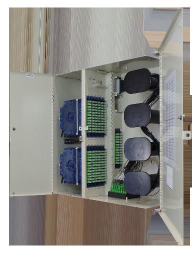
FieldSmart ® Fiber Delivery Point (FDP)
Indoor 144-Port PON Wall Box
Technical Specifications
FieldSmart Indoor 144 Port PON Wall Mount Panel
Dimensions 23.59” H x 24.56” W x 8.35” D (599.19 mm x 623.82 mm x 212.09 mm)
Port Density
Distribution: Up to 144 ports
Feeder: Up to 24 ports
Cassette Types Supported Clearview® Blue and Clearview Classic
Connector Types SC/UPC, SC/APC, LC/UPC, LC/APC, MPO
Cable Types Indoor Riser, Indoor Plenum, Indoor/Outdoor
Splice Capacity 12 splices in each Clearview Cassette
Storage Capacity One meter of 900 μm fiber and up to 5 meters of jacketed fiber
Material 18 gauge cold rolled steel (almond powder coating)
Splitter Capacity Up to 6 ruggedized splitters
Configured Part Numbers
Disclaimer/Note: Paper configurator shown is for reference only and should not be used to configure a saleable product configuration. All options shown on paper configurators may not be available or compatible with other options listed. Please contact your Clearfield representative for assistance in product configurations.
7 5 Select Mode / Type Select Feeder
1 = Singlemode, non-ribbon
2 = Singlemode, ribbon
3 = Multimode (62.5)
9 = No fiber – multimode
2 Select Clearview Cassette
B = Clearview Blue
Z = Clearview Classic
3 Select Port Count
X X X = Port count in increments of 12
0 = No fiber – singlemode
Select Cable Construction
A = Indoor riser rated (IFC)
B = OSP riser rated
C = Indoor, plenum rated (IFC)
E = OSP (non-rated)
M = OSP (armored, non-rated)
F = Patch and splice (loose tube)
Z = None or patch and splice (ribbon)
A = 12 port feeder cassette patch only 144 box
B = 24 port feeder cassette 144 box only
Z = No feeder
8 Select Cable Exit *
2 = Top left
4 = Bottom left
Z = None or patch and splice (ribbon)
XXXM or XXXF
XXXM = Length in meters
XXXF = Length in feet
* Cable exit is defined by which direction the cable exits the panel when viewing it from the front.
F = LC/UPC
H = LC/APC
FieldSmart® Fiber Delivery Point (FDP)
Indoor 288-Port Wall Box
Application
The Indoor 288-Port Wall Box has been optimized for MDU applications. Utilizing the Clearview ® Black Ribbon Cassette, the FieldSmart Fiber Delivery Point (FDP) gives service providers plug-and-play integration based upon the configuration requirements of their application. Feeder fibers, distribution fibers, splitter modules, splicing and unused splitter output storage are all contained within a single, rugged, wall-mountable enclosure. Housing a swing-out bulkhead in a compact footprint wall box, with the ability to house up to 9 WaveSmart ® High Density 1 x 32 Splitters, provides for a flexible deployment of FTTH networks in an MDU environment as well as a variety of applications in carrier networks and CATV environments.
Description
This indoor wall box is Clearview optimized, allowing the user to scale the bulkhead from 12 to 288 distributed ports and up to 24 feeder ports. This bulkhead accepts the Clearview Black Patch and Splice Cassettes (Clearfield’s in-cassette splicing solution) utilizing ribbon cable. A side lock provides security enabled doors for extra protection and a solid enclosure to protect fiber terminations from damage.
Designed from conception to provide fast, easy fiber jumper routing and ease of access to all circuits, the wall box system is craft-friendly, keeping the installer’s needs for quick deployment, intuitive use and ease of maintenance as the top priority. Easily wall mounts with one person; the main body of the box attaches to the wall. The bulkhead swings open for easy access to the front and rear of the cassettes.
Features and Benefits
Integrity
• Terminations designed, tested and certified to Telcordia GR-326
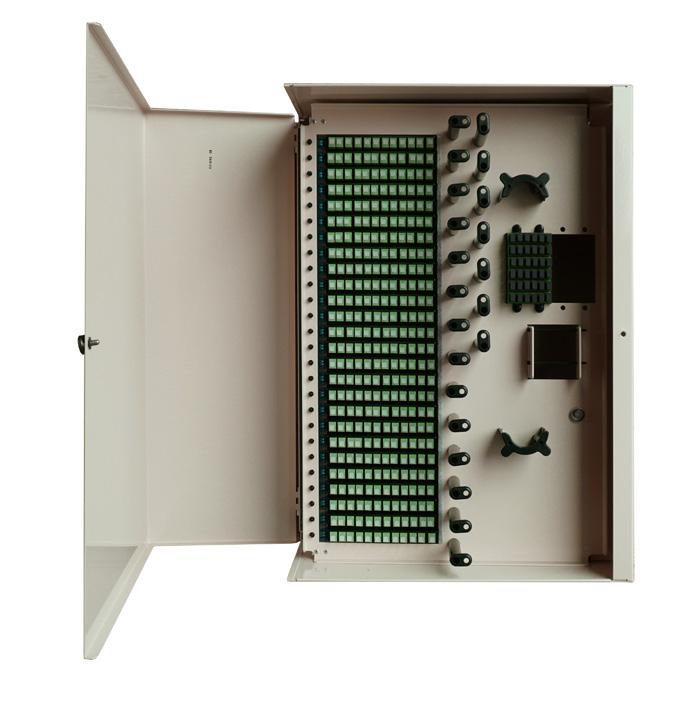
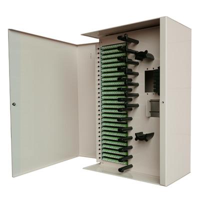

• Clearfield® FiberDeep® Guarantee: 0.2 dB insertion loss or less, exceeding industry standards
• Designed to comply with GR-3125
• Supports all industry standard singlemode connectors
• 100% performance tested for final mechanical inspect
Protection
• Radius protected storage of cabling
• Integrated fiber management protects fiber from micro-bend and macro-bend damage
• Door locks via a 216 bolt with tab option for padlock
Access
• Removable left open front door with the ability to swing 90 degrees
• Top and bottom entry/exit points for cables
Investment
• With user-defined feeder/distribution port counts, scalable to 288 distributed ports and 24 feeder ports of fiber using Clearview Black Cassettes
• Utilizes the Clearview Black Cassettes with ribbon cable only
FieldSmart® Fiber Delivery Point (FDP)
Indoor 288-Port Wall Box
Technical Specifications
FieldSmart 288-Port Wall Box
Dimensions 17” W x 24” H x 9” D (431.8 mm x 609.6 mm x 228.6 mm)
Port Density Up to 288 distributed ports and 24 feeder ports
Cassette Types Supported Clearview ® Black
Splitter Up to 9 WaveSmart High Density 1 x 32 Splitter with 900 micron legs
Connector Types
SC/UPC, SC/APC, MPO
Cable Types Indoor Riser, Indoor Plenum, Indoor/Outdoor
Splice Capacity 12 splice configurations in each Clearview Cassette Material 16 gauge cold rolled steel (almond powder coating)
Pre-Configured Part Numbers - Empty (No Cassettes)
Part Number Description
WB288-CFWM
FieldSmart Fiber Delivery Point Wall Box, 288 Max. Cap., Indoor Rated, For Black Cassettes and WaveSmart High-Density Splitters, No Fiber Loaded, CLFD
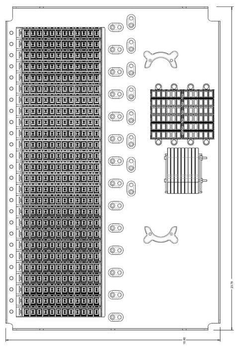
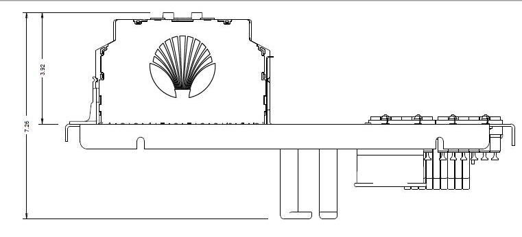
FieldSmart® Fiber Delivery Point (FDP)
Indoor 288-Port Wall Box
Configured Part Numbers - Indoor 288 In-Cassette Splicing
• Clearview Black Cassette
• Only Supports Ribbon Splicing
• Splitters are Not Installed
1
1
Configured Part Numbers - Indoor 288 MPO Cassette
• Clearview Black Cassette with Rear 12F MPO
• Complete Plug-and-Play
• Splitters are Not Installed
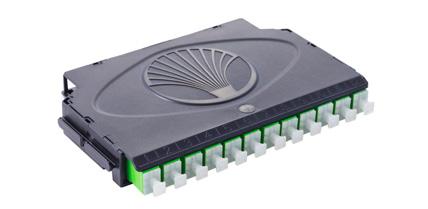
Connector Type
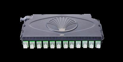
1 Select Feeder Port Count
1 = 12
2 = 24 Z = No Feeder Ports
2
FieldSmart® Fiber Delivery Point (FDP)
Indoor 288-Port Wall Box
Configured Part Numbers - Indoor 288 Patch Only
• Supports (1) Feeder Cable and (2) Distribution Cables
• Splitters are Installed
FieldSmart® Fiber Delivery Point (FDP)
Indoor 288-Port Wall Box
Accessories Pre-Configured Part Numbers
Part Number Description
E1Z-012-C2F-SUB
EL3-012-C1F-SUB
Clearview Black in-cassette splicing with SC/APC. * Different connector types available, contact your Clearfield representative.
Clearview Black MPO Cassette with SC/APC. * Different connector types available, contact your Clearfield representative.
KE1-CAA High Density Splitter (1x32)
FMA-MZZ Ribbon Fan-Out Kit
FMA-XXX-235 Staging Plate; Protected Foam Block for Unterminated Splitter Legs
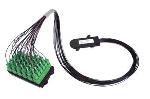

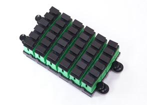
FMA-XXX-162 Feeder Cable Strain Relief, 1/2” Sealcon

005397 & 004117 (Order Both PNs) Distribution Cable Strain Relief, 1” Sealcon

YOURx ® Flex Box
Application
Carriers are faced with many challenges when cabling MDUs in both existing (brownfield) and new construction (greenfield). One such challenge is how to manage incoming duct, while supporting varying number of subscribers in different configurations with slack management while also reducing installation time. Clearfield’s YOURx Flex Box addresses these challenges with a flexible and scalable solution all within a single wall box.
Description
The YOURx Flex Box is a secure, modular wall box with slide-in aggregator plate that supports multiple cable entries like, individual fiber cables, conduit and microduct in an organized manner. Installers simply push the microduct into the aggregator plate and they are ready to pull fiber. Slack storage is provided for both incoming and outgoing fiber in separate areas to reduce service interruptions when turning up additional subscribers. The drop wheel feature accommodates up to 16 individual drop wheel assemblies with each drop wheel supporting up to a 200’ (60.96 m) of FieldShield ® StrongFiber storage. The SmartRoute Plate can also be mounted in the Flex Box, providing spool technology and MPO connectorization. Using the Clearview ® Cassette, Drop Wheel assembly or SmartRoute Plate allows for a plugand-play concept which reduces installation time.
Features and Benefits Integrity
• Utilizes the Clearview Blue Cassette, Clearview xPAK and FieldShield Drop Wheel
• 1” inside mounting hole pattern for multiple applications
• Dual snap ensures lid secures to box Protection
• NEMA 4 Rated
• Secured with 216 can wrench bolt
• Security screw with ability to secure with padlock
• Gasket seal
• Grounding lug included Access
• Easy to install with both internal and external mounting holes
• Top and bottom entry/exit points Investment
• Scalable
• Slide-in aggregator plates eliminate the need for additional duct organizer
• Clearview Cassette, Clearview xPAK, Drop Wheel or SmartRoute Plate

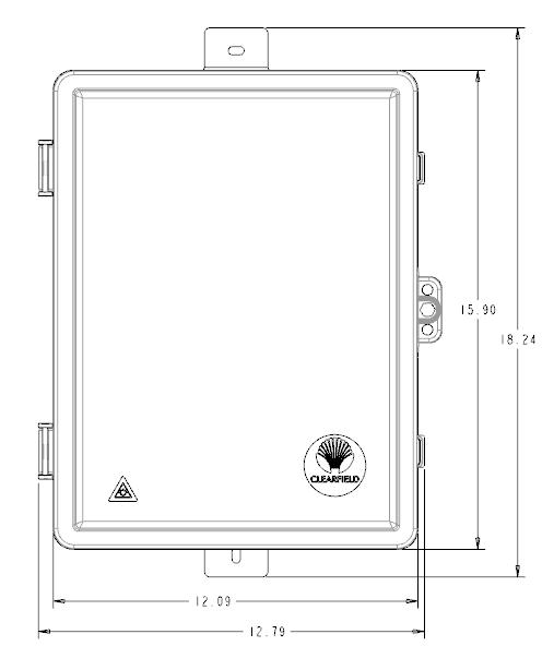
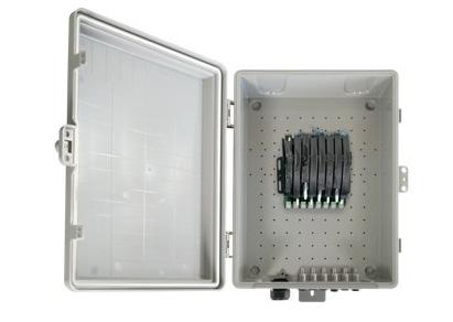
YOURx ® Flex Box
Technical Specifications
Material
Port Density
x
x
UV rated, flame retardant, V0 rated
Four cassettes (48 ports), up to 16 in drop wheel, SmartRoute Plate 24 port
Connectivity Types Clearview ® Blue, Drop Wheel, SmartRoute Plate
Aggregator Plate
Combo Plate - microduct supports (24) 10/6mm or (24) 8.5/6mm. Universal Plate - lay in applications. Universal Combo - lay in with microduct. PON Plate - microduct (32) 10/6mm or (32) 8.5/6mm.
Drop Wheel Fiber type - FieldShield ® StrongFiber
Drop Wheel Connector Pullable SC/APC and SC/UPC to standard SC/APC and SC/UPC
Drop Wheel Cable Length
200 feet (60.96 m) FieldShield StrongFiber
Drop Wheel Material Black Thermoplastic


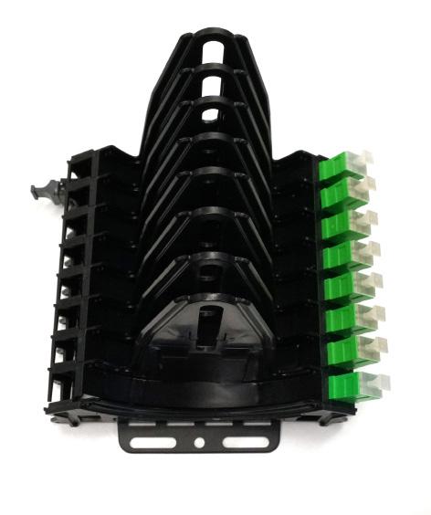


Plates
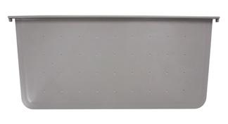
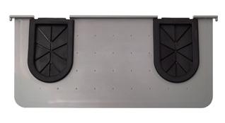

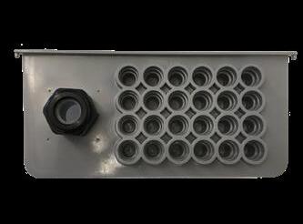
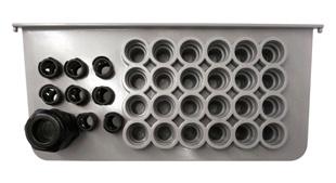
Configured Part Numbers
Select Module Type
B = Cassette Customer Splice
C = Empty Cradle Assembly Input Male MPO E = Empty Cradle Assembly with Splitter, Input SC/APC
M = Loaded Cradle Assembly Input Male MPO N = Cassette Input Male MPO
S = Loaded Cradle Assembly With Splitter, Input SC/APC
10/6 mm or 8.5/6mm FlexPorts
YOURx ®
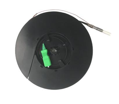
Part Number Description
DW-001-SCU-SCU 200F Drop wheel, loaded with loaded with 200 feet (60.96 m) FieldShield StrongFiber, terminated with pullable SC/ UPC to SC/UPC connectors
DW-001-SCA-SCA 200F Drop wheel, loaded with loaded with 200 feet (60.96 m) FieldShield StrongFiber, terminated with pullable SC/ APC to SC/APC connectors
Pre-Configured Empty Box Part Numbers
Part Number Description
FDP-xWBF-BPLATE Empty Flex Box with blank plate and cable management kit.
FDP-xWBF-CPLATE Empty Flex Box with combo plate and cable management kit. No FlexPort fittings.
FDP-xWBF-CPLATE-24
FDP-xWBFCPLATE-24-85
Empty Flex Box with combo plate and cable management kit. Loaded with 24 10/6mm FlexPort fittings.
Empty Flex Box with combo plate and cable management kit. Loaded with 24 8.5/6mm FlexPort fittings.
FDP-xWBF-PPLATE-32 Empty Flex Box with PON plate and cable management kit. Loaded with 32 10/6mm FlexPort fittings.
FDP-xWBF-PPLATE-328.5MM Empty Flex Box with PON plate and cable management kit. Loaded wtih 24 8.5/6mm FlexPort fittings.
FDP-xWBF-UPLATE Empty Flex Box with universal plate and cable management kit.
FDP-xWBF-UCPLATE Empty Flex Box with universal grommet combo plate with microduct ports and cable management kit.
Pre-Configured Splice Box (Indoor Only)
Part Number Description
FDP-XWBF-UPLATESPLICE-01
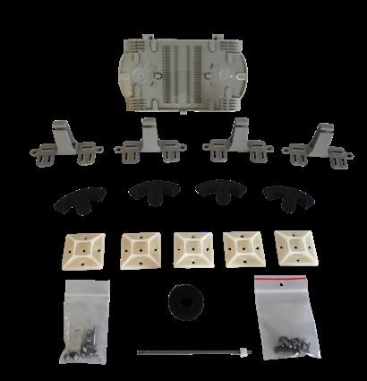
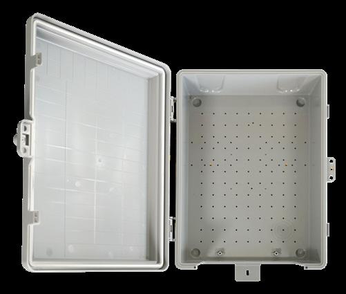
YOURx FieldSmart Flex Box, 48 Max. Cap., Universal Plate, Hardware Kit and Ship Along 48 Position Splice Tray
Individual Drop Wheel
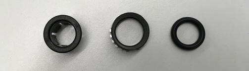
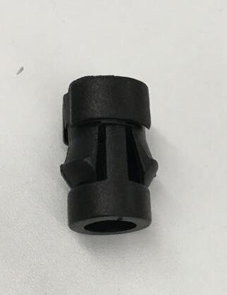
FlexPort Fitting for Combo and Duct Plate, 10 mm, Quantity - 12
FlexPort Fitting for Blank Plate (Requires Drilled 1/2 Hole), 10 mm, Quantity - 1
FlexPort, 10 mm (Hard to remove, install with caution)
SmartRoute Plate - Fits Inside Flex Box
How to Order:
1. Order Empty Box
2. Order Configured SmartRoute Plate
Configured Part Numbers with Pigtail Assembly
Plate FlexPort Fitting for Blank Plate, 10 mm Qty: 1 (Requires Drilled ½ Hole) P/N 018835
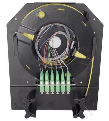
Configured Part Numbers with Pigtail Assembly
1
012 = 12 ports
024 = 24 ports
036 = 36 ports
048 = 48 ports
A = SC/UPC
C = SC/APC
F = LC/UPC
H = LC/APC
A = IFC Riser
B = OSP Riser Rated
C = IFC Plenum
E = OSP (Non-rated)
M = OSP (Armored, Non-rated)
T = FLATdrop (Non-toneable)
W = FieldShield
* 10/6mm Flexports will match the port count selected in #1
FieldShield ® StrongFiber Drop Wheel
Application
Carriers are faced with key challenges when cabling for both brownfield and greenfield MDU deployments. The challenges are varied and include how to install multiple drops from a single connection point when distances are unknown, accommodating slack storage and ensuring alignment of capital investment with customer take rates in a plug-and-play design.
Description
FieldShield StrongFiber Drop Wheel assemblies address these key challenges with a compact, scalable and flexible quick-deploy platform. The end to end plug-and-play solution utilizes a spool concept with 200 feet (60.96 m) of StrongFiber that is preterminated with a pullable SC/APC or SC/UPC connector. The drop wheel is easily deployed by extending the wheel from the cradle and pulling the fiber through the microduct or conduit. Once the pullable connector reaches its destination, the connector is mated to an adapter or directly into an ONT, providing a complete plug-and-play solution. Any remaining slack is stored and managed on the Drop Wheel. The Drop Wheel reduces turn-up time by offering a faster, simplified and splice-free installation which can be performed by a general technician. Cradle assemblies can be configured to ship unpopulated, allowing for individual drop wheels to be purchased separately to scale and align capital investment with subscriber revenue. Cradle assemblies have the option to be configured with splitters or MPO connector for speedy installations.
Features and Benefits
Integrity
• StrongFiber is designed, tested and certified to GR-20
• StrongFiber Deploy Reel has been designed, tested and certified to GR-63
• Terminations designed, tested and certified to Telcordia GR-326
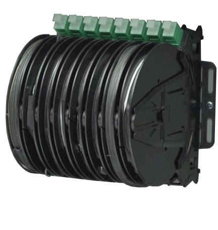
• Clearfield FiberDeep ® Guarantee: 0.2 dB insertion loss or less, exceeding industry standards
• Supports singlemode SC connectors
Protection
• Craft friendly spool technology allows installers to pull the exact amount of cable required
• FieldShield StrongFiber bend-insensitive (G.657.A2) fiber protects optical signal with minimal to zero attenuation
• Lightweight with low coefficient of friction to maximize pull distances
Access
• Black in color
• Spooled with small form factor 900 µm
• Indoor implementations
Investment
• Pre-terminated cable spools reduce upfront deployment costs by simplifying site survey inspections
• Scalable, quick and easy deployment allows capital investment to align with customer take rates
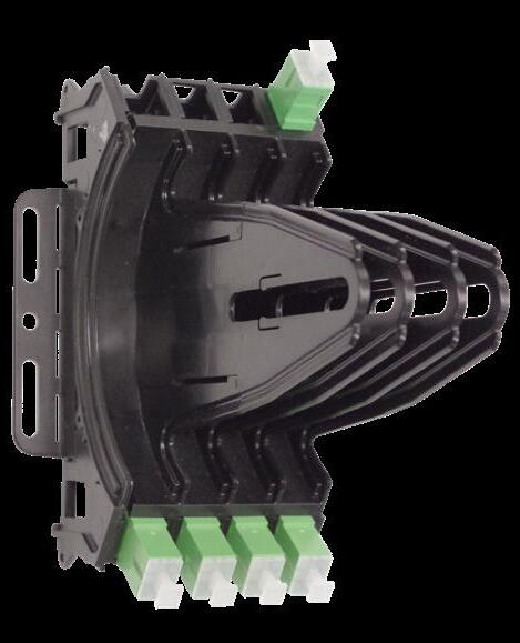

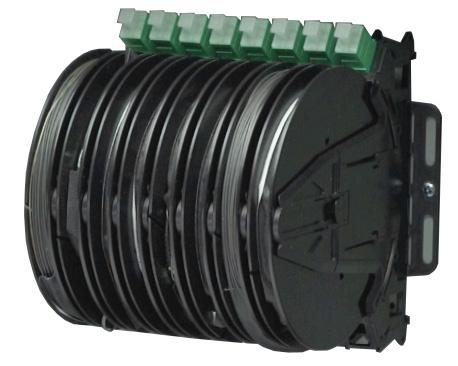
Empty Drop Wheel Cradle
Individual Drop Wheel
FieldShield Loaded Drop Wheel Assembly
FieldShield ® StrongFiber Drop Wheel
Technical Specifications
FieldShield StrongFiber Drop Wheel
Drop Wheel Fiber Type FieldShield StrongFiber Connectors
or
Cable Length 200 feet (60.96 m) per wheel
Drop Wheel Material Black Thermoplastic
Drop
Drop Wheel Cradle Dimensions
Pre-Configured Part Numbers
Empty Drop Wheel Cradle with Installed Splitter
DWC-SCA4-Splitter Empty 4 position Drop Wheel Cradle with 1 x 4 splitter installed with SC/APC adapters, no Drop Wheels
DWC-SCU8-Splitter Empty 8 position Drop Wheel Cradle with 1 x 8 splitter installed with SC/UPC adapters, no Drop Wheels
DWC-SCA8-Splitter Empty 8 position Drop Wheel Cradle with 1 x 8 splitter installed with SC/APC adapters, no Drop Wheels
DWC-SCU12-Splitter Empty 12 position Drop Wheel Cradle with 1 x 12 splitter installed with SC/UPC adapters, no Drop Wheels
DWC-SCA12-Splitter Empty 12 position Drop Wheel Cradle with 1 x 12 splitter installed with SC/APC adapters, no Drop Wheels
DWC-SCU16-Splitter Empty 16 position Drop Wheel Cradle with 1 x 16 splitter installed with SC/UPC adapters, no Drop Wheels
DWC-SCA16-Splitter Empty 16 position Drop Wheel Cradle with 1 x 16 splitter installed with SC/APC adapters, no Drop Wheels
Drop Wheel Cradle with MPO Installed
DWC-SCU4-MPO Empty 4 position Drop Wheel Cradle with male MPO installed with SC/UPC adapters, no Drop Wheels
DWC-SCA4-MPO Empty 4 position Drop Wheel Cradle with male MPO installed with SC/APC adapters, no Drop Wheels
DWC-SCU8-MPO Empty 8 position Drop Wheel Cradle with male MPO installed with SC/UPC adapters, no Drop Wheels
DWC-SCA8-MPO Empty 8 position Drop Wheel Cradle with male MPO installed with SC/APC adapters, no Drop Wheels
DWC-SCU12-MPO Empty 12 position Drop Wheel Cradle with male MPO installed with SC/UPC adapters, no Drop Wheels
DWC-SCA12-MPO Empty 12 position Drop Wheel Cradle with male MPO installed with SC/APC adapters, no Drop Wheels
DWC-SCU16-MPO Empty 16 position Drop Wheel Cradle with male MPO installed with SC/UPC adapters, no Drop Wheels
DWC-SCA16-MPO Empty 16 position Drop Wheel Cradle with male MPO installed with SC/APC adapters, no Drop Wheels
Individual Drop Wheel - To Be Installed into Empty Cradle
Part Number Description
DW-001-SCU-SCU 200F Drop Wheel loaded with 200’ (60.96 m) FieldShield StrongFiber SC/UPC
DW-001-SCA-SCA 200F Drop Wheel loaded with 200’ (60.96 m) FieldShield StrongFiber SC/APC
FieldShield ® StrongFiber Drop Wheel
Loaded Drop Wheel Cradle with Installed Splitter Part Number Description
DW-SCX4U-Splitter
DW-SCX4-Splitter
DW-SCX8U-Splitter
DW-SCX8-Splitter
DW-SCX12U-Splitter
DW-SCX12-Splitter
DW-SCX16U-Splitter
DW-SCX16-Splitter
Loaded 4 position Drop Wheel Cradle with 1 x 4 splitter installed with SC/UPC adapters, includes Drop Wheels
Loaded 4 position Drop Wheel Cradle with 1 x 4 splitter installed with SC/APC adapters, includes Drop Wheels
Loaded 8 position Drop Wheel Cradle with 1 x 8 splitter installed with SC/UPC adapters, includes Drop Wheels
Loaded 8 position Drop Wheel Cradle with 1 x 8 splitter installed with SC/APC adapters, includes Drop Wheels
Loaded 12 position Drop Wheel Cradle with 1 x 12 splitter installed with SC/UPC adapters, includes Drop Wheels
Loaded 12 position Drop Wheel Cradle with 1 x 12 splitter installed with SC/APC adapters, includes Drop Wheels
Loaded 16 position Drop Wheel Cradle with 1 x 16 splitter installed with SC/UPC adapters, includes Drop Wheels
Loaded 16 position Drop Wheel Cradle with 1 x 16 splitter installed with SC/APC adapters, includes Drop Wheels
Loaded Drop Wheel Cradle with MPO Installed
DW-SCU4-MPO
Loaded 4 position Drop Wheel Cradle with MPO installed with SC/UPC adapters, includes Drop Wheels
DW-SCA4-MPO Loaded 4 position Drop Wheel Cradle with MPO installed with SC/APC adapters, includes Drop Wheels
DW-SCU8-MPO
DW-SCA8-MPO
Loaded 8 position Drop Wheel Cradle with MPO installed with SC/UPC adapters, includes Drop Wheels
Loaded 8 position Drop Wheel Cradle with MPO installed with SC/APC adapters, includes Drop Wheels
DW-SCU12-MPO Loaded 12 position Drop Wheel Cradle with MPO installed with SC/UPC adapters, includes Drop Wheels
DW-SCA12-MPO Loaded 12 position Drop Wheel Cradle with MPO installed with SC/APC adapters, includes Drop Wheels
DW-SCU16-MPO Loaded 16 position Drop Wheel Cradle with MPO installed with SC/UPC adapters, includes Drop Wheels
DW-SCA16-MPO Loaded 16 position Drop Wheel Cradle with MPO installed with SC/APC adapters, includes Drop Wheels
SmartRoute Plate
Application
The SmartRoute Plate is designed to fast-track and simplify fiber installations when landing up to 12 fibers in any environment. Clearfield’s SmartRoute Plate combines cable, spooling technology and MPO connectorization in a stand-alone wall plate design. This allows for maximum flexibility and efficient use of available space. The compact design can be pre-configured to terminate up to 12 fibers. This SmartRoute is an ideal solution for use in MDUs, SFUs, cell towers and business class services.
Description
The SmartRoute Plate contains one internal spool that can hold up to 200 feet (60.96 m) of 3 mm, 12-fiber plenum micro-cable or 12-fiber FieldShield ® Cable. The plate can provide up to 12 connections on the front of the spool with an MPO or pigtail breakouts on the back side of the spool.
Features and Benefits
Integrity
• Terminations are designed, tested and certified to Telcordia GR-326
• Clearfield FiberDeep ® Guarantee: 0.2 dB insertion loss or less, exceeding industry standards
• Supports all industry standard singlemode and multimode connectors
• 100% performance tested for insertion loss, return loss and final mechanical inspect Protection
• Craft-friendly SmartRoute spool technology allows the installer to pullout the exact amount of cable required, and leaving the remaining slack safely stored on the spool Access
• Wall mount
• Slack storage for drop cables Investment
• Pre-connectorized options eliminate labor and speed network construction
• Scalable to 12 ports of fiber
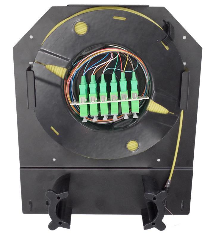
SmartRoute Plate
Technical Specifications
SmartRoute Plate
Dimensions
Port Density
6 and 12 ports = SC, 6 ports = LC Duplex
Connector Types SC/UPC, SC/APC, MPO, LC/UPC, LC/APC
Cable Types Indoor Plenum Rated IFC/FieldShield ®
Maximum Internal Spool Cable Length 200 feet (60.96 m)
Mounting Options Wall Mount
Configured Part Numbers
P = Plate Only
1 2 Select Plate
A = SC/UPC
C = SC/APC
F = LC/UPC
H = LC/APC Select Front Connector Type 4 5 6
3 Select Cable Type
1 = SM stranded non-ribbon, plenum rated
3 = MM stranded non-ribbon, plenum rated
4 Select Cable Construction Y = IFC Plenum W = FieldShield
5 Select Number of Fibers
1 = 12 Fibers
3 = 6 Fibers 7 8 9
6 Select Rear Connector Type
A = SC/UPC
C = SC/APC
F = LC/UPC
H = LC/APC
N = MPO Male Pushable
P = MPO Female Pushable
Z = None
7 Select Rear Breakout B = 1 meter C = ½ meter Z = None
8 Select Rear Upjacketing
A = 900 µm B = 2mm Z = None
9 Select Length
FieldSmart ® Fiber Delivery Point (FDP) Small
Wall Box
Application
Engineered to land small port count fiber terminations and optical components as conveniently as possible, the FieldSmart FDP Small Wall Box is optimized for delivery of a single Clearview ® xPAK with up to six fibers. The lockable, NEMA 4 rated enclosure is compact, making it ideal for a variety of applications, including harsh environment locations surrounding fiber demarcation, entrance facilities, FTTP drop boxes and cell backhaul. Additional applications include MDU, business class services, power and wind farms and DOT/Traffic monitoring.
Description
The FieldSmart Small Wall Box was designed for the Clearview xPAK. The Clearview xPAK supports small fiber count scenarios of 2, 4 or 6 fibers in a discrete footprint. A craft-friendly design, using industry standard 216 as a locking method, no special tool is required. Four knockout ports, each supporting a ½ sealcon cable strain relief for incoming or outgoing cables for optimum cable retention. The backplane was designed with 1-inch hole spacing which allows maximum flexibility for mounting cable management rods or any additional hardware needed to support your fibers.
Features and Benefits
Integrity
• RUS listed
• Utilizing the Clearview xPAK, it supports industry standard SC and LC singlemode connectors
• Dual snap locks to ensure lid seals to base
• Mounting hole pattern for multiple applications
Protection
• Radius protected storage for up to 15 feet of buffer tube
• NEMA 4 rated
• Security screw with ability to secure with padlock
• Gasket seal
• Ground lug included
Access
• Small design facilitates ease of use in crowded environments
• Easy to install with both internal and external mounting holes
• Two bottom entry/exit points
Investment
• Patch and splice (Clearfield’s in-cassette splicing solution) or patch only
• Surface or pole mount capable
• Flame retardant PVC for durability
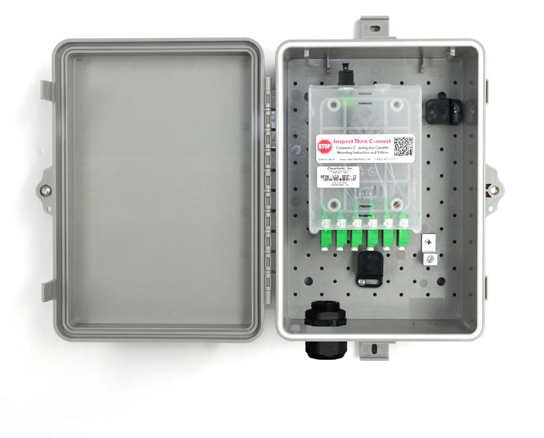
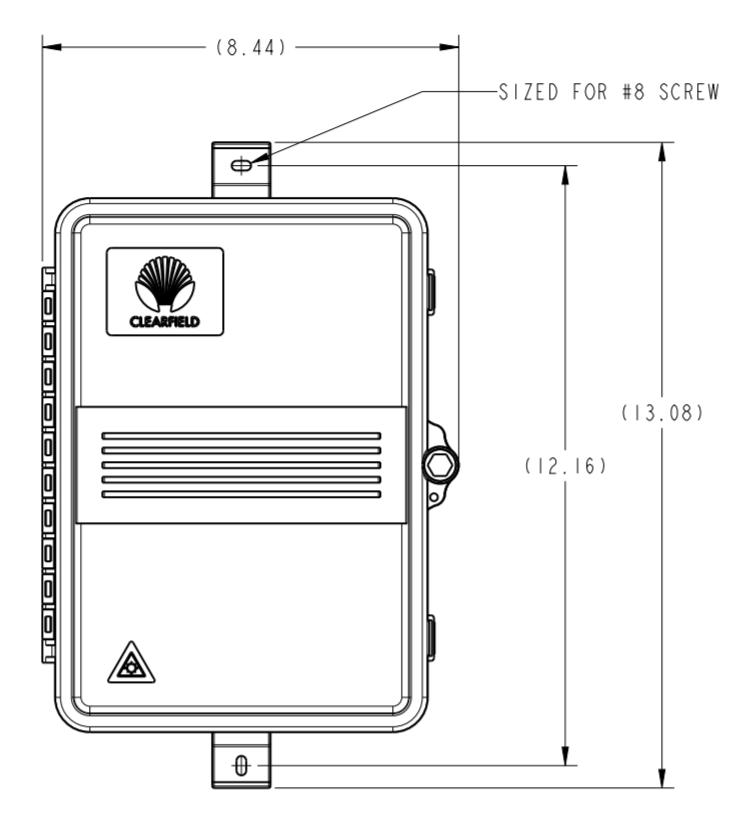
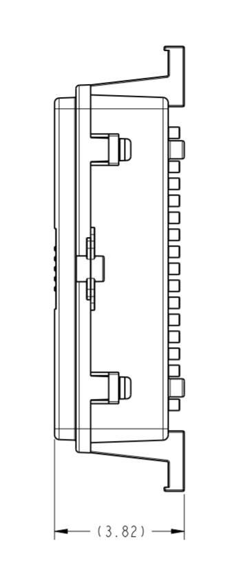
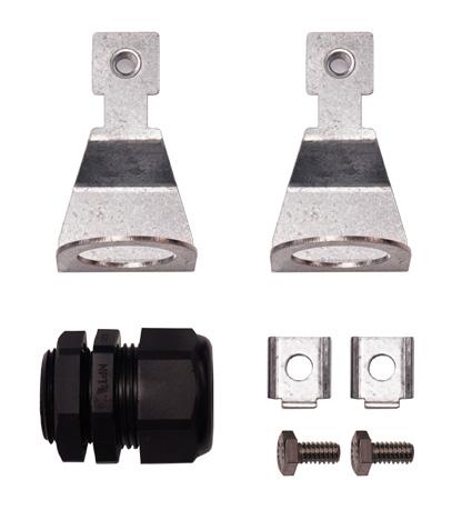
FDP-xAK1
FieldSmart ® Fiber Delivery Point (FDP)
Small Wall Box
Technical Specifications
FieldSmart Small Wall Box
Dimensions
Port Density Up to six ports
Cassette Types Supported Clearview ® xPAK
Connector Types
Cable Types
SC/UPC, SC/APC, LC/UPC, LC/APC, MPO
Indoor Riser, Indoor Plenum, Indoor/Outdoor, Outdoor (Riser/Non-Rated), Outdoor Armored (Riser/NonRated), FieldShield ®
Splice Capacity Six splices in each Clearview xPAK
Storage Capacity One meter of 900 μm fiber and up to 5 meters of jacketed fiber
Material UV stabilized, flame retardant polymer (PVC)
Pre-Configured Part Numbers
Configured Part Numbers
A =
A = IFC riser
B = OSP riser rated
C = IFC plenum
E = OSP (non-rated)
M = OSP (armored, non-rated)
T = Flat drop (non-toneable)
W = FieldShield
FieldSmart ® Fiber Delivery Point (FDP)
Macro/Small Cell Wall Box
Application
Engineered to land small to medium fiber terminations in a convenient wall box design, the FieldSmart FDP Macro/Small Cell Wall Box is ideal for a variety of applications, including harsh environment locations surrounding fiber demarcation, entrance facilities, FTTP drop boxes and cell backhaul.
Description
The FieldSmart FDP Macro/Small Cell Wall Box comes with a factory-installed cable assembly, supporting up to 24 fibers. Factory-installed cable reduces the operating costs of fiber deployment by reducing installation times.
Features and Benefits
Integrity
• RUS listed
• Supports industry standard SC, LC and MPO singlemode connectors
• Dual snap locks to ensure lid seals to base
• NEMA 4 rated
Protection
• Slack storage clips for both incoming and outgoing fibers
• Security screw with ability to secure with padlock
• Gasket seal
• Grounding lug included
Access
• Wall and pole mount
• Easy to install with both internal and external mounting holes
• Two bottom ¾” (19.05 mm) entry/exit ports are supported with ship-along Sealcon connectors
Investment
• Pre-connectorized cable assemblies eliminate labor and speed network construction
• Patch only
• One box for a variety of application uses

FieldSmart ® Fiber Delivery Point (FDP)
Macro/Small Cell Wall Box
Technical Specifications
FieldSmart FDP Macro/Small Cell Wall Box
Port Density
Supports 12 SC or 24 LC ports
Connector Types SC/UPC, SC/APC, LC/UPC, LC/APC, MPO
Cable Types
Indoor Riser, Indoor Plenum, Outdoor (Riser/Non-Rated), FieldShield ®
Material UV stabilized, flame retardant polymer (PVC)
Mounting Options Wall and Pole Mount
Configured Part Numbers


006 = 6 ports
012 = 12 ports
024 = 24 ports (LC Only) Select Port Count 2
A =
C =


2 = Singlemode, ribbon Select Mode/Type
or XXXF 1 = Singlemode, non-ribbon

= Length in feet
(armored,
FieldSmart ® Fiber Delivery Point (FDP) Large Wall Box
Application
Ideal for any small count fiber scenario, the FieldSmart Large Wall Box accepts up to two Clearview ® Cassettes, providing up to 24 fibers in a discrete footprint without sacrificing fiber management. Designed to land small port count fiber terminations and optical components as conveniently and inexpensively as possible, this flexible solution is perfectly suited for in-building needs, such as business class demarcations, MDU distribution points and IDF locations in enterprise networks as well as pole-mount applications in outside plant environments. When paired with a Clearview MPO Breakout Cassettes and a StrongFiber Deploy Reels, the FieldSmart Large Wall Box provides a complete plug-andplay solution for the MDU environment.
Description
The FieldSmart Large Wall Box complements the FieldSmart Fiber Delivery Point (FDP) Wall Box line, which provides three unique wall box designs that deliver 36 to 144 ports of fiber management in a traditional sheet-metal configuration. As a lower cost alternative to sheet-metal designs, this lockable, NEMA 4 rated enclosure is consistent with Clearfield’s long-standing reputation of delivering simple solutions for complex problems.
Designed around the Clearview Cassette, the FieldSmart Large Wall Box uses the same components as the other elements of the FieldSmart product platform. Slack storage is an integrated component of the solution with the Clearview U-Mount bracket accepting up to two Clearview Cassettes and providing up to 15 feet (4.57 m) of buffer tube slack storage. Unique to Clearfield ® design is the ability to bring multiple fiber sheaths into the FieldSmart Large Wall Box. Each sheath will be protected within their own Clearview Cassette, providing service providers the ability to isolate one fiber sheath from another within the same enclosure.
Features and Benefits
Integrity
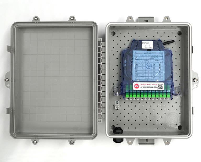
• Utilizing the Clearview Cassettes, it supports industry standard SC and LC singlemode connectors
• Dual snap locks to ensure lid seals to base
• Mounting hole pattern for multiple applications
Protection
• Radius protected storage for up to 15 feet (4.57 m) of buffer tube
• NEMA 4 rated
• Security screw with ability to secure with padlock
• Gasket seal
• Ground lug included
Access
• Small design facilitates ease of use in crowded environments
• Easy to install with both internal and external mounting holes
• Two bottom entry/exit points
Investment
• Patch and splice (Clearfield’s in-cassette splicing solution) or patch only
• Surface or pole mount capable
• Flame retardant PVC for durability

FieldSmart ® Fiber Delivery Point (FDP)
Large Wall Box
Technical Specifications
FieldSmart Large Wall Box
Dimensions
Port Density Up to 24 ports
Cassette Types Supported Clearview ® Blue
Connector Types SC/UPC, SC/APC, LC/UPC, LC/APC, MPO
Cable Types
Indoor Riser, Indoor Plenum, Indoor/Outdoor, Outdoor (Riser/Non-Rated), Outdoor Armored (Riser/NonRated), FieldShield ®
Splice Capacity 12 or 24 splice configurations in each Clearview Cassette
Storage Capacity One meter of 900 μm fiber and up to 5 meters of jacketed fiber
Material UV stabilized, flame retardant polymer (PVC)
Pre-Configured Part Numbers
Part Number Description
FDP-xWB2-12-SCA-B Wall Box with (12) SC/APC ports in one Clearview ® Cassette
FDP-xWB2-12-SC-B Wall Box with (12) SC/UPC ports in one Clearview Cassette
FDP-xWB2-12-LC-B Wall Box with (12) LC/UPC ports in one Clearview Cassette
FDP-xWB2-12-LCA-B Wall Box with (12) LC/APC ports in one Clearview Cassette
FDP-xWB2-24-SCA-B Wall Box with (24) SC/APC ports in two Clearview Cassette
FDP-xWB2-24-SC-B Wall Box with (24) SC/UPC ports in two Clearview Cassette
FDP-xWB2-24-LC-B Wall Box with (24) LC/UPC ports in two Clearview Cassette
FDP-xWB2-24-LCA-B Wall Box with (24)
Configured Part Numbers
StreetSmart ®
Mini FEC Wall Box
Application
When an application requires splicing IFC (intra-facility) cable to an OSP (outside plant) cable and space is a concern, the StreetSmart Mini FEC Wall Box is your product of choice. The Mini FEC is a scalable wall box that has a maximum capacity of 96 loose tube splices with cable management and slack storage. Each splice tray comes equipped with a 24-fiber heat shrink fusion splice chip. The Mini FEC is an ideal solution for use in MDUs, SFUs, cell towers and business class services.
Description
The Mini FEC Wall Box can support both indoor and outdoor environments. Each Mini FEC comes equipped with industry standard splice trays, cable management clips, a ground lug and two ship-along cable clamps. Each splice tray can support 24 splices with a maximum capacity of four splice trays per wall box or 96 splices. Slack storage is available for up to 5’ (1.52 m) per buffer tube and up to 5’ (1.52 m) per IFC micro-distribution cable.
Features and Benefits
Integrity
• Industry standard splice tray
• NEMA 4 rated
• Material is high impact flame retardant PVC3 with high column strength and lowcoefficient PBT
Protection
• Ruggedized storage clips
• Security screw with ability to secure with padlock
• Gasket seal
Access
• Wall mount capable
• Two bottom ¾” (19.05 m) entry/exit ports
• Removable splice trays
Investment
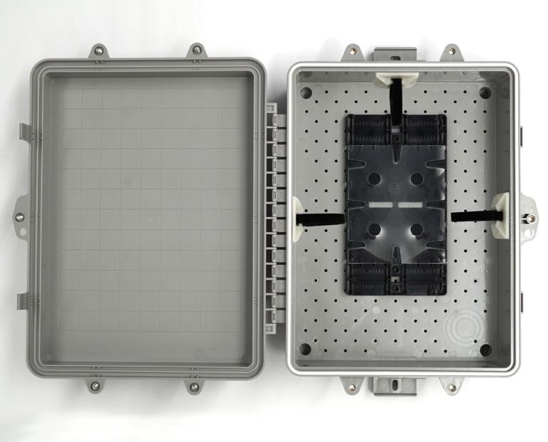
• Splice trays support both loose tube and ribbon constructions for single and mass fusion (ribbon) splicing
• Scalable with 24 splices per tray loose tube or 72 splices per tray ribbon
• Complete cable management solution installed from the factory
• Two Sealcon connectors are included
StreetSmart ® Mini FEC Wall Box
Technical Specifications StreetSmart Mini FEC Wall Box
Pre-Configured Part Numbers
FieldSmart ® Fiber Delivery Point (FDP)
Wall Box Accessories
Strain Relief ½” (12.70 mm) Cable
Description
Strain relief that seals incoming or outgoing round, flat drop or 3mm cable assemblies. Requires ¾” (19.05 mm) drilled hole.
Pre-Configured Part Numbers
Strain Relief ¾” (19.05 mm) Cable
Description
Strain relief that seals incoming or outgoing round, flat drop or 3mm up to ¾”. Requires 1” (25.4 mm) drilled hole.
Pre-Configured Part Numbers
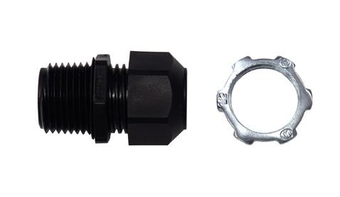

Sealcon Adapter ¾” (19.05 mm)
Description
Kit for securing for cables. Kit includes strain relief, nut, O-ring, and two grommets. Requires 1” (25.40 mm) drilled hole.
Pre-Configured Part Numbers

Sealcon Adapter 1” (25.40 mm)
Description
Kit for securing for cables. Kit includes strain relief, nut, O-ring, and three grommets. Requires 1 1/4” (31.75 mm) drilled hole.
Pre-Configured Part Numbers
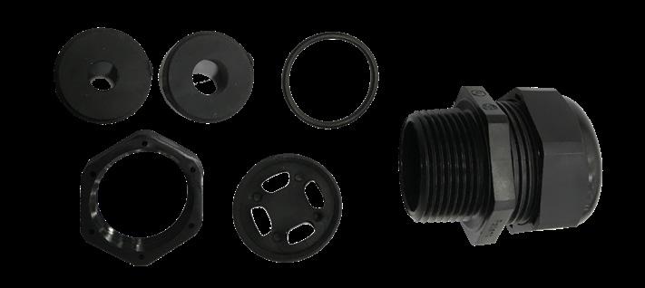
FieldSmart ® Fiber Delivery Point (FDP) Wall Box Accessories
1” (25.40 mm) Grommet
Description
Grommet used to secure cables 10 mm microduct.
Pre-Configured Part Numbers
Hole Plug
Description
Rubber
Pre-Configured Part Numbers
Velcro
Description
Velcro square for attaching misc items into wall box.
Pre-Configured Part Numbers
Security Bit
Description
Bit for securing the pin-in-hex screw on wall boxes.
Pre-Configured Part Numbers
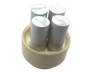


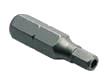
Tape
Description
Grommet tape to help secure cable assemblies into sealcon adapter.
Pre-Configured Part Numbers
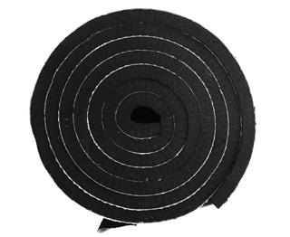
StreetSmart™ Fiber Hand-Off Box
Application
The StreetSmart Fiber Hand-Off Box serves as the demarcation point between the backhaul provider and the mobile network operator. Designed with a hinged plate and 216 locking mechanism, a secure separation is created between the wireless and wireline provider. The Fiber Hand-Off Box provides a single test access point to an angled adapter plate, designed to offer ease of cleaning and maintenance.
Description
The StreetSmart Fiber Hand-Off Box comes in plug-and-play and patch only configurations. The plug-and-play configuration utilizes a MPO adapter for easy installation. The patch only configuration is a factoryinstalled cable ranging in different cable construction and different lengths. With factory-installed cable management rods, removable door and no special tool requirement, the StreetSmart Fiber Hand-Off Box is extremely craft-friendly.
The Fiber Hand-Off Box supports up to two incoming cables and eight distribution cables using a split grommet design. Each distribution port is labeled for easy circuit identification.
Features and Benefits
Integrity
• Designed, tested and certified to Telcordia GR-771
• Terminations designed, tested and certified to Telcordia GR-326
• MPO terminations designed, tested and certified to Telcordia GR-1435
Protection
• Sealcon fitting with multiple media grommets
• Gasket cover for protection from the elements
• 216 locking feature (can wrench)
Access
• Secure plate between backhaul provider and mobile operator
• Removable tethered hinged door
• Pole, wall and aerial mounting
Investment
• Angled adapters for ease of cleaning
• Multiple cable management guides
• Two cable entry ports

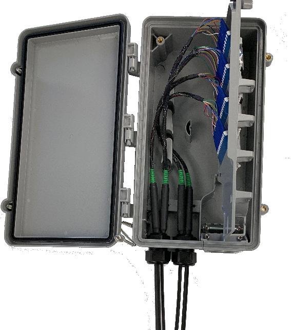
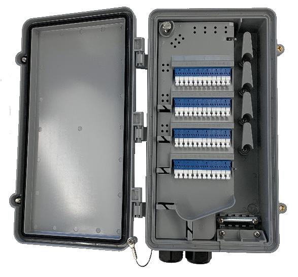

Pre-terminated
MPO Assembly
StreetSmart™ Fiber Hand-Off Box
Technical Specifications
StreetSmart Fiber Hand-Off Box
Dimensions 13” H x 8.0” W x 3.0” D
Box Options Pre-Terminated Cable or MPO Fiber Assemblies
Connector Types LC/APC, LC/UPC, SC/APC, SC/UPC or MPO
Cable Entrance Two entry ports
Cables Exits Eight flat drop with lay in design
Labeling Designation label
Mounting Options Pole, Wall and Aerial
Pre-Configured Part Numbers
1 Select Port Count
06 = 6 ports 24 = 24 ports
12 = 12 ports 36 = 36 ports (LC Only)
18 = 18 ports 48 = 48 ports (LC Only)
2 Select Distribution Connector
A = SC/UPC
C = SC/APC
F = LC/UPC
H = LC/APC
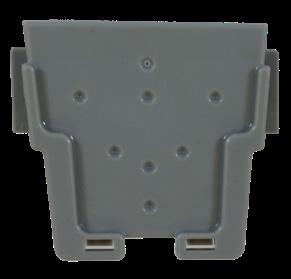
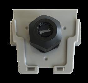
(Pre-terminated to stub) 5
1 = Singlemode (Non-ribbon)
2 = Singlemode (Ribbon) Z= No Feeder Cable 5 Select Right Exit Plate
Select Jacket Construction
A = Indoor IFC Riser T= FLATdrop (Non-Toneable)
= OSP Riser U = FLATdrop (Toneable) C = Indoor Plenum IFC W = FieldShield E = OSP Non-rated
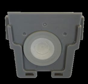
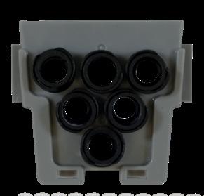
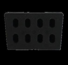
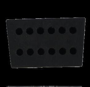
MPO-Input Configured Part Numbers
1 Select Port Count
06 = 6 ports
12 = 12 ports (LC Only)
18= 18 ports
24=24 ports
36=36 ports (LC Only)
48= 48 ports (LC only)
Select Distribution Connector
= SC/UPC
= SC/APC
= LC/UPC
Select Right Exit Plate
= LC/APC B = Blank
= Flat Drop
= Hole Plug
= Microduct – 10/6 mm
= 4.8 mm S = Strain Relief
StreetSmart™
Fiber Hand-Off Box
Configured Part Numbers
Mounting Options
Part
W2W-AER-01
W2W-PMM-01
W2W-PMW-01
W2W-WMB-01
Bracket Aerial Strand
Bracket Metal Pole Includes Two Hose Clamps
Bracket Wood Pole Includes Lag Screws
Bracket Wall Mount/Monopole (No Screws)
StreetSmart™
Small Count Fiber Hand-Off Box
Application
The StreetSmart Small Count Fiber Hand-Off Box serves as a network demarcation point between the backhaul provider and the network operator or as a demarc point for small count MDUs. Designed with a hinged plate and 216 locking mechanism, access is secured between craft responsibilities. The craft-friendly GR-771 box can be mounted aerially, on a pole or on a wall. The compact design makes it ideally suited for inside a monopole.
Description
The StreetSmart Small Count Fiber Hand-Off Box can be configured in either 6 or 12 terminations in both SC or LC connections. The StreetSmart Small Count Hand-Off Box comes in two configurations. The plug-and-play option utilizes an MPO or HMFOC (hardened multifiber optical connector) connector or the patch only which comes with factory installed cable in length up to 3000’. Designed with a tethered removable door, lay in grommet, angled adapter for easy cleaning and testing, no special tool requirements makes the box extremely craft-friendly.
Features and Benefits
Integrity
• Designed, tested & certified to GR-771
• Designed to comply with NEMA 4
• Terminations designed, tested and certified to GR-326
• MPO terminations designed, tested and certified to Telcordia GR-1435
Protection
• 216 locking (can wrench)
• Lay in grommet with cable retention clamp
• Industrial grade door gasket
Access
• Secure plate between backhaul provider and mobile operator
• Removeable tethered door
• Angled adapter for easy testing and cleaning
Investment
• Cable management guides
• Lay in grommet for both backhaul and network provider
• Cable retention clamps

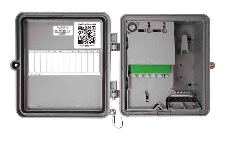
StreetSmart™
Small Count Fiber Hand-Off Box
Technical Specifications
StreetSmart Small Count Fiber Hand-Off Box
Dimensions
Box Option
Output Connector
8” H x 8” W x 3” D
Plug-and-play or patch only
SC/APC, SC/UPC, LC/UPC, LC/APC or HMFOC
Input Connector MPO, HMFOC or Patch Only
Cable Entrance
Single entrance for both provider and network
Labeling Designation label on door
Mounting Options
Plug-and-Play
Pole, Wall or Aerial
MPO-Input Configured Part Numbers
1
2 Select Distribution Connector
A =
Blank Strain Relief Hole Plug
Microduct Flat Drop
4.8 mm
StreetSmart™
Small Count Fiber Hand-Off Box
Patch Only
Configured Part Numbers
1 Select Port Count
06 = 6 ports
12 = 12 ports (LC Only)
2 Select Distribution Connector
A = SC/UPC
C = SC/APC
F = LC/UPC
H = LC/APC
HMFOC to LC/UPC
Configured Part Numbers
W
1 Select Right Exit Plate
B = Blank
F = Flat Drop
H = Hole Plug
M = Microduct – 10/6 mm
R = 4.8 mm
S = Strain Relief
3 Select Pigtail Assembly
A = IFC Riser
B = OSP Riser Non-Armored
C = IFC Plenum
M = OSP Non-Rated Armored
T = Flat Drop Non-Toneable
U = Flat Drop Toneable
2 Select Fiber Assembly Length Patch Only Options: XXXXF or XXXXM HMFOC Options are Limited to:
0001F = 1 Foot
0050F = 50 Feet
0100F = 100 Feet
0200F = 200 Feet
Pre-Configured Part Numbers - Mounting Brackets
4 Select Right Exit Plate
B = Blank
F = Flat Drop
H = Hole Plug
M = Microduct – 10/6 mm
R = 4.8 mm
S = Strain Relief
FieldSmart ®
SCD TAP Box
Application
Engineered to land FTTH fiber terminations as conveniently as possible, the FieldSmart SCD TAP Box is optimized for delivery of FLEXdrop via a FLEXdrop Deploy Reel and Slack Storage Reel. The lockable enclosure is compact and sealed, making it ideal for a variety of applications, including harsh environment locations surrounding the fiber demarcation point. Additional applications include MDU and business class services.
Description
The FieldSmart SCD TAP Box offers single or dual count fiber deployment in a discrete footprint and without sacrificing proper fiber management. With the FieldSmart SCD TAP Box, enclosures are designed packaged to make FTTH more cost-effective and efficient than previously thought possible. Standardizing on a craft-friendly, building block architecture reduces the operating costs of fiber deployment by reducing installation times and inventory carrying requirements.
Features and Benefits
Integrity
• UV Stabilized
• Utilizing the FLEXdrop Deploy Reel, it supports industry standard SC and LC singlemode connectors
• Dual snap locks to ensure lid seals to base
• Mounting hole pattern for multiple applications
Protection
• Designed to comply to GR-771 and NEMA-4
• Gasket seal
• Ground lug included
Access
• One-Inch on center holes for easy installation of deploy reel mounting pin
• Easy to install with both internal and external mounting holes
• Two bottom entry/exit points utilizing multi-purpose strain reliefs
• Option for adapter mounting bracket
Investment


• Holds up to 200 feet of FLEXdrop on Deploy Reel, with 100 feet of 3mm cable slack storage
• Surface or pole mount capable
• Flame retardant PVC for durability
Pre-Configured Part Numbers
FieldSmart ®
Mini TAP Box
Application
Engineered to land FTTH terminations as conveniently as possible, the FieldSmart Mini TAP Box is optimized for delivery of FieldShield ® FLEXdrop ® via a FLEXdrop Deploy Reel and Slack Storage Reel. The lockable enclosure is compact and sealed, making it ideal for a variety of applications, including harsh environment locations surrounding the fiber demarcation point.
Description
The FieldSmart Mini TAP Box offers single or dual count fiber deployment in a discrete footprint and without sacrificing proper fiber management. The FieldSmart Mini TAP Box is designed to make FTTH more cost-effective and efficient than previously thought possible. Standardizing on a craft-friendly, building block architecture reduces the operating costs of fiber deployments by reducing installation times and inventory carrying requirements.
Features
and Benefits
Integrity
• UV Stabilized
• Supports industry standard SC and LC singlemode connectors with the FLEXdrop Deploy Reel
• Dual snap locks ensure lid seals to base
• Mounting hole pattern for multiple applications
Protection
• Designed to comply to GR-771 and NEMA-4
• Gasket seal
• Ground lug included
Access
• One-Inch on center holes for easy installation of deploy reel mounting pin
• Easy to install with both internal and external mounting holes
• Two bottom entry/exit points utilizing multi-purpose strain reliefs
• Option for adapter mounting bracket
Investment
• Holds up to 100 feet of FLEXdrop on Deploy Reel, with 50 feet of 3mm cable slack storage
• Surface or pole mount capable
• Flame retardant PVC for durability
Pre-Configured Part Numbers
FDRG-ZZZZ-MGLZ Mini-TAP Box, L-Bracket (No Adapter), 3/4” Adapter and Grommet

FDRG-ZZZZ-HHZH Mini-TAP Box, Deploy Reel Mounting Plate with No Adapters, Strain Relief and Strain Relief
FDRG-ZZZZ-HHLZ Mini-TAP Box, L-Bracket (No Adapter), Strain Relief and Strain Relief
CraftSmart ® Test Access Point (TAP) Box
Application
The CraftSmart Test Access Point (TAP) Box gives the service provider an accessible exterior access point to test fiber integrity before it enters the customer premise. This solution allows the service provider the ability to identify potential issues in conductivity from outside of the customer premise location.
Description
The CraftSmart TAP Box is a two part closure that will accommodate up to four fibers for test and access purposes. The base of the unit will allow up to four splices from the feeder cable to individual drops into the customer premise. Duplex SC adapters allow for installation of pre-terminated or field terminated fiber to be connectorized for test and access of the fiber - to determine feeder and drop issues.
Two grommeted in/out ports on the bottom of the unit provide easy installation of both feeder and drop cables. The unit is lockable to minimize customer tampering. There are grounding options available inside the TAP Box that will allow grounding of the feeder and drop cables. It also has built in access to exterior grounding built into the unit. Multiple mounting options are available to meet all applications. The TAP Box is available with private labeling on the front cover to easily identify service provider’s identification.
Features and Benefits Integrity
• Fiber terminations are designed, tested and certified to Telcordia and RUS compliant
• Supports industry standard SC singlemode connectors
• 100% performance tested for insertion loss, return loss and final mechanical inspections Protection
• Overlapping cover seals unit from environmental elements
• Two rubber grommets provide sealing of feeder and drop cables
• Lock hole provided for reduced tampering

• Enclosure made of high-impact UV resistant thermal plastic material - to resist and withstand corrosive environments
• Designed to meet NEMA 3 criteria
• Integrated fiber management protects fiber from micro and macro damage
• Special coupler available for use with FieldShield ® Microduct Access
• Slide on cover allows for easy access to closure
• Rubber grommets allow for easy installation of feeder and drop cables
• Grounding bar inside of unit allows for grounding of feeder and drop cables, as well as built in accessibility to exterior grounding
• Dual SC adapters (one or two) allows for easy access for testing and troubleshooting
• Available in SC/APC, SC/UPC, LC/APC or LC/UPC
• Wall and pole mount applications available
• Built in splice tray allows for maximum flexibility Investment
• Available with pre-terminated feeder and drop cables, which minimizes splicing and connectorization field costs
• Patch and splice (Clearfield’s in-cassette splicing solution) compatible
• Available all hours of the day, without customer needing to be there to identify potential problems
CraftSmart ® Test Access Point (TAP) Box
Technical Specifications
CraftSmart Test Access Point (TAP) Boxes
Dimensions 7.3” H x 8.57” W x 1.67” D (185.42 mm x 217.68 mm x 42.42 mm)
Connector Availability/ Capacity
Cable Support and Tie Off Options
Empty: No connector
One dual SC/APC or SC/UPC; two dual SC/APC or SC/UPC; quad LC/UPC or LC/APC; two quad LC/ UPC or LC/APC
Not included with TAP Box - MUST BE ORDERED SEPARATELY.
TAP-GL-KIT (one clamp per kit) Strength member tie off kit for flat drop and dielectric cable
TAP-ARM-GL-KIT (one clamp per kit) Ground lug bracket for armored cable - no strength member tie off
Splice Capacity Four
Cable Entrance/Exit
Private Labeling
Pre-terminated Feeder and Drop Cable
Mounting Options
One on each port (two total). If using FieldShield ® Microduct, order one FS-CPLR-10MM-10MM-TAP per exit
Standard: comes with Clearfield ® logo.
Private labeling available (500 piece minimum). Contact Clearfield sales representative for details
Available: Please contact your Clearfield sales representative
Wall Mount: Standard
Vinyl Siding Mount: TAP-VS-KIT
Pole Mount: TAP-PM-KIT
Configured Part Numbers
Select Box Type
= Splice only (1)
= Patch and splice
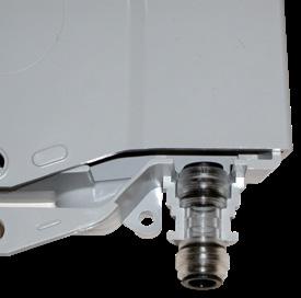
(5)
Ordering Notes
1.Splice only - empty box
2.Standard product unless noted - last three digits will be 000
3.500 piece minimum in effect for custom logo - customer must provide artwork to Clearfield ®
For pre-terminated feeder and drop cable assemblies, please refer to Clearfield’s application guide for ordering information. For custom configurations, please contact your Clearfield sales representative.
CraftSmart®
TAP Splice Box
Description
The CraftSmart TAP Splice Box supports up to 2 subscribers. It is used as a termination point for the feeder cable to connect with the drop cable in FTTx network system, integrating fiber splicing, distribution, storage and cable connection in one solid protection box.
Features and Benefits
• Total enclosed structure: dust-proof, anti-aging, water-proof design with IP-66 protection level.
• Enclosure includes clamping for feeder cable and drop cable, fiber splicing, fiber storage and distribution ports.
• Cable, pigtails, patch cords have distinct cable management route paths for fiber protection. Splice tray and SC adapters are designed for easy installation and maintenance
• Installation options for wall or pole mounting and suitable for both indoor and outdoor uses.
• 2 ports cable entrance for drop cable.
Technical Specifications
CraftSmart TAP Splice Box
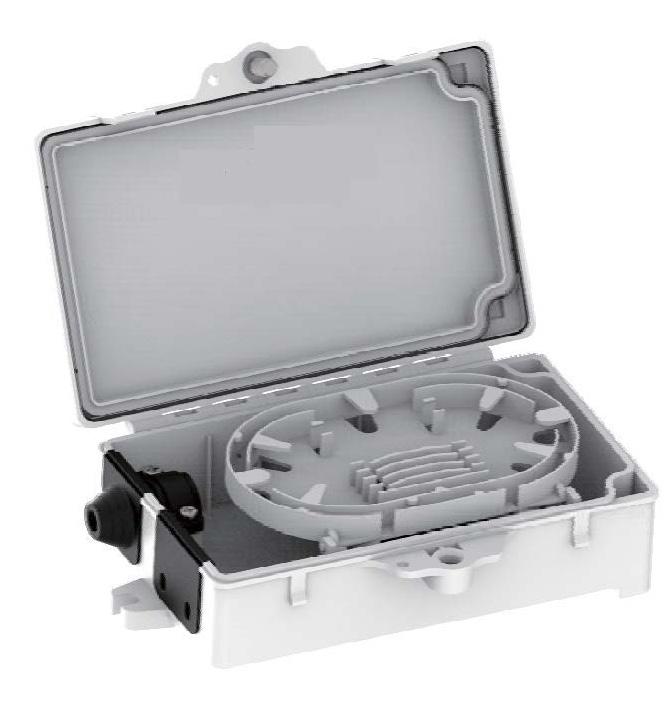
x 6.50 x 1.75 Inches

Accessories
Splice tray and cable management tool, protection sleeves, hose clamp, rubber seal for cable entrance, extra lock and latch key.
CraftSmart® TAP Splice Box
Pre-Configured Part Numbers
Part Number Description
022051
TAPS-SCA
TAPS-SCU
Tap Box, with Splice Tray, Removable Grommets Left and Right, 4 x 6.5 x 1.75”, White, Indoor Use
Tap Box, with Splice Tray, with SC/APC Adapter, Removable Grommets Left and Right, 4 x 6.5 x 1.75”, White, Indoor Use
Tap Box, with Splice Tray, with SC/UPC Adapter, Removable Grommets Left and Right, 4 x 6.5 x 1.75”, White, Indoor Use
022051G Tap Box, with Splice Tray, Removable Grommets Left and Right, 4 x 6.5 x 1.75”, Gray, Outdoor Use
TAPS-SCA-G
TAPS-SCU-G
Tap Box, with Splice Tray, with SC/APC Adapter, Removable Grommets Left and Right, 4 x 6.5 x 1.75”, Gray, Outdoor Use
Tap Box, with Splice Tray, with SC/UPC Adapter, Removable Grommets Left and Right, 4 x 6.5 x 1.75”, Gray, Outdoor Use
CraftSmart®
Fiber Outlet
Application
The CraftSmart Fiber Outlet allows for easy demarcation inside the premise and cable management for incoming feeder cable.
Description
The CraftSmart Fiber Outlet can accommodate 4 entrance points for 3mm cable and up to 4 output of SC adapter ports. The splice cassette is hinged and easily removable for nonsplicing applications. This small indoor enclosure provides both bend limiting protection and a secure termination point to connect the entrance fiber to the included equipment jumper.
Features
and Benefits
Integrity
• Supports industry standard SC adapters
Protection
• Snap-on cover for duct free protection
Access
• Easy installation
• Accommodates 4 adapter ports
• Four cable entrance points
Investment
• Cables can be connected without splicing
• Hinged and detachable splice tray
Technical Specifications
Pre-Configured Part Numbers
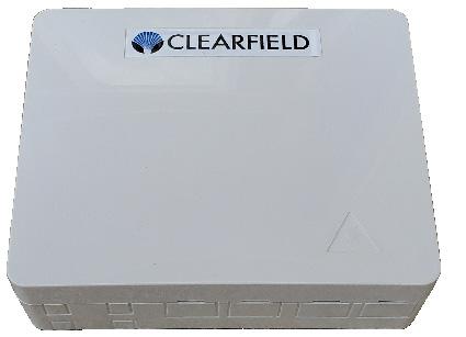

CraftSmart® Application
TAP-Splice Home Deployment Kit
A CraftSmart Home Deployment Kit (HDK) extends Clearfield’s field-proven fiber management expertise and leading-edge fiber connectivity performance all the way into the home. Starting with the Test Access Point (TAP) solution of your choice, the Home Deployment Kit packages the required patch cords, fiber jack (Clearfield’s CraftSmart Fiber Outlet) and necessary adapter and splice sleeve installation accessories in a single box. Truck rolls are minimized and customer turn-up is rapid. Choose the CraftSmart TAP-Splice HDK for environments where splicing or patch is needed and minimal slack storage is desired within the unit mounted outside the home.
CraftSmart TAP-Splice
The CraftSmart TAP-Splice is a IP-66 patch or splice drop termination point that allows for any type of fiber drop cable to be spliced to an included 1-meter fiber pigtail and plugged into the supplied coupler. This method allows the pre-terminated FLEXdrop entrance fiber to be easily plugged into the TAP-Splice and routed into the home. The 4.0 x 6.5 x 1.75 inch footprint of the CraftSmart TAP-Splice enables providers to discretely place the fiber termination on the side of the home.
The CraftSmart Fiber Outlet can accommodate 4 entrance points for 3mm cable and up to 4 SC adapter ports. The splice tray is hinged and easily removable for non-splicing applications. This small indoor enclosure provides both bend limiting protection and a secure termination point to connect the entrance fiber to the included equipment jumper.
Integrity
• IP-66 Protection
• Clamping for feeder cable and drop cable
• Integrated splice tray Access
• Accepts 10mm microduct and standard flat drop
• Removable rubber entrance/exit grommets Investment
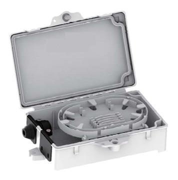
• Access available without customer needing to be there to identify potential problems
CraftSmart Fiber Outlet
Integrity
• Supports industry standard SC adapters Protection
• Snap-on cover for dust free protection Access
• Easy installation
• Accommodates 4 adapter ports
• Four cable entrance points Investment
• Cables can be connected without splicing
• Hinged and detachable splice tray
FieldShield FLEXdrop
Integrity
• Available in singlemode
• Supports all industry standard connectors Protection

FieldShield FLEXdrop cable has an OSP-rated PVDF jacketing that allows for transition of FLEXdrop from the OSP environment directly into the inside plant, with the added benefit of being UL listed for plenum applications. FLEXdrop can be used as a building wrap at turn-up, maximizing installation efficiency.
• UL listed for plenum applications for single fiber only
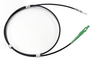
• Passed UV testing and measurement standards per ASTM G155 for UL 1581
• Bend-insensitive (G.657.A2) fiber protects optical signal with minimal to zero attenuation down to a 10 mm radius
• OSP rated PVDF jacketing provides ruggedized protection for the patchcord or pigtail
• Staple-ready for walls, joists and around corners, with Crown T-18 staples
• Swellable yarns for water blocking capabilities Access
• Standard color is black with an option for off-white
• Suitable for all types of indoor and outdoor implementations (duct required for aerial and direct bury) Investment
• Quick and easy deployment allows capital investment to be aligned to customer take rates
CraftSmart® TAP-Splice Home Deployment Kit
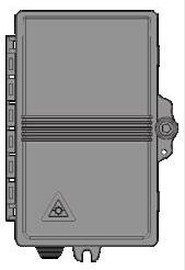
Technical Specifications
CraftSmart® TAP-Splice Home Deployment Kit
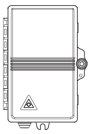
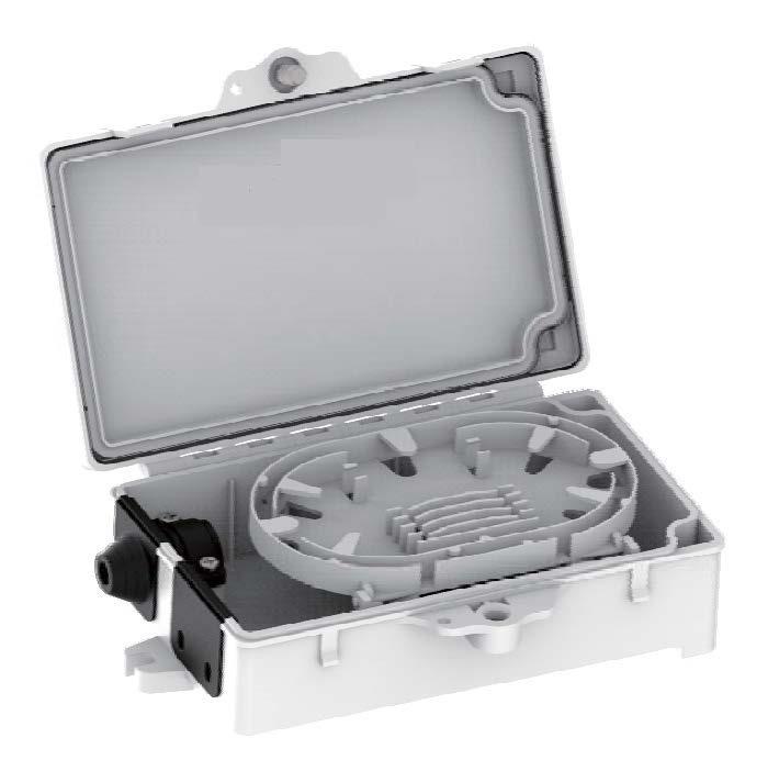
CraftSmart TAP-Splice Front View
Open with Splice Tray
FieldSmart® Mini TAP Home Deployment Kit
Application
FieldSmart ® Mini TAP Home Deployment Kit (HDK) extends Clearfield ® ’s field-proven fiber management expertise and leading-edge fiber connectivity performance all the way into the home. With the FIeldSmart Mini TAP, the Home Deployment Kit packages the required patch cords, fiber jack (Clearfield’s CraftSmart ® Fiber Outlet) and necessary adapter installation accessories in a single box. Truck rolls are minimized and customer turn-up is rapid. Choose the FieldSmart Mini TAP HDK for environments where plug-and-play along with internal slack storage is desired within the unit mounted outside the home.
The FieldSmart Mini TAP provides a secure demarcation point between the service provider network and SFU. Mini TAP gives the network service provider both the ability to store slack fiber as well as provide a test access point (TAP) for ease of deployment and network maintenance without needing to have access to the interior of the customer premise.
FLEXdrop ® Deploy Reel mounts easily on the supplied pin, allowing 50, 75 and 100 feet of pre-connectorized FLEXdrop to be deployed into the premise. With the ability to accept a variety of drop cables with up to 50’ of incoming cable slack storage, Mini TAP can be wall or pole mounted, and can be integrated into any network architecture and deployment.
The CraftSmart Fiber Outlet can accommodate 4 entrance points for 3mm cable and up to 4 SC adapter ports. The splice tray is hinged and easily removable for non-splicing applications. This small indoor enclosure provides both bend limiting protection and a secure termination point to connect the entrance fiber to the included equipment jumper.
Integrity
• Supports industry standard SC adapters
• Includes entrance points with multi-purpose strain reliefs Protection
• UV Stable Polycarbonate
• Snap and screw latching system Access
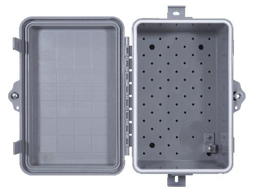
• Accepts 10mm microduct, 3mm cable, standard flat drop and Small Form Factor FLATdrop Investment
• Access available without customer needing to be there to identify potential problems
Integrity
• Supports industry standard SC adapters Protection
• Snap-on cover for dust free protection Access
• Easy installation
• Accommodates 4 adapter ports
• Four cable entrance points Investment
• Cables can be connected without splicing
• Hinged and detachable splice tray FieldShield FLEXdrop
Integrity
• Available in singlemode
• Supports all industry standard connectors
• Terminations designed, tested and certified to GR-326
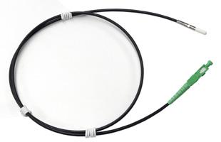
FieldShield ® FLEXdrop cable has an OSP-rated PVDF jacketing that allows for transition of FLEXdrop from the OSP environment directly into the inside plant, with the added benefit of being UL listed for plenum applications. FLEXdrop can be used as a building wrap at turn-up, maximizing installation efficiency.
• FLEXdrop fiber cable designed, tested and certified to GR-20 Protection
• UL listed for plenum applications for single fiber only
• Passed UV testing and measurement standards per ASTM G155 for UL 1581
• Bend-insensitive (G.657.A2) fiber protects optical signal with minimal to zero attenuation down to a 10 mm radius
• OSP rated PVDF jacketing provides ruggedized protection for the patchcord or pigtail
• Staple-ready for walls, joists and around corners, with Crown T-18 staples
• Swellable yarns for water blocking capabilities Access
• Standard color is black with an option for off-white
• Suitable for all types of indoor and outdoor implementations (duct required for aerial and direct bury) Investment
• Easy deployment allows capital investment to be aligned to customer take rates
FieldSmart Mini TAP
CraftSmart Fiber Outlet
FieldSmart® Mini TAP Home Deployment Kit
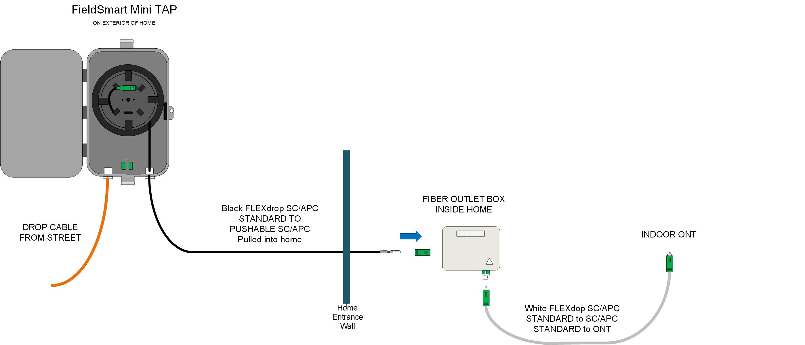
Technical Specifications
FieldSmart
CraftSmart
FieldSmart® Mini TAP Home Deployment Kit
FieldShield FLEXdrop
Fiber Corning ClearCurve Optical Fiber or equivalent
Clad Diameter
125.0 ± 0.7 μm
Coating Diameter (Uncolored) 235 - 245 μm
Bend-Insensitive
Bend-Insensitive Fiber G.657.A2
Color Code TIA/EIA 598 (US Standard)
Fiber Count
Single and dual fiber
Pushable Connectors FieldShield SC/UPC and SC/APC
Standard Connectors SC/UPC and SC/APC
Mode
Internal Fiber
μm
Outside Diameter 0.118” (3 mm)
Color Black or white
Material PVDF
Bend-Radius Standard to G.657.A2 specifications
Installation Temperature -22°F to 131°F (-30°C to 55°C)
Operating Temperature -40°F to 176°F (-40°C to 80°C)
Installation Tension 20 lbf
Markings
Home Deployment Kits Include:
• FieldSmart Mini TAP
• CraftSmart Fiber Outlet
• Black Entrance Cable: FLEXdrop Pushable Cable (Configurable adapter and lengths)
• White Equipment Cable: FLEXdrop Pushable Cable (Configurable adapter and lengths)
Configured Part Number
Mini TAP Home Deployment Kit

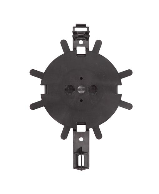
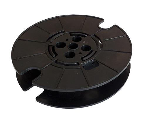
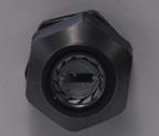

Slack Storage Reel-50
FLEXdrop Deploy Reel
Mini TAP Multi-Purpose Strain Relief Deploy Reel Mounting Plate
FieldSmart® Application
SCD-TAP Home Deployment Kit
FIeldSmart SCD-TAP Home Deployment Kit (HDK) extends Clearfield’s field-proven fiber management expertise and leading-edge fiber connectivity performance all the way into the home. With the FIeldSmart SCD-TAP, the Home Deployment Kit packages the required patch cords, fiber jack (Clearfield’s CraftSmart Fiber Outlet) and necessary adapter installation accessories in a single box. Truck rolls are minimized and customer turn-up is rapid. Choose the FieldSmart SCD-TAP HDK for environments where plug-and-play along with internal slack storage is desired within the unit mounted outside the home.
The FieldSmart SCD-TAP provides a secure demarcation point between the service provider network and SFU. SCDTAP gives the network service provider both the ability to store slack fiber as well as provide a test access point (TAP) for ease of deployment and network maintenance without needing to have access to the interior of the customer premise. FLEXdrop Deploy Reel mounts easily on the supplied pin, allowing 100, 150 and 200 feet of pre-connectorized FLEXdrop to be deployed into the premise. With the ability to accept a variety of drop cables, SCD-TAP can be wall or pole mounted, and can be integrated into any network architecture and deployment.
The CraftSmart Fiber Outlet can accommodate 4 entrance points for 3mm cable and up to 4 SC adapter ports. The splice tray is hinged and easily removable for non-splicing applications. This small indoor enclosure provides both bend limiting protection and a secure termination point to connect the entrance fiber to the included equipment jumper.
Integrity
• Supports industry standard SC adapters
• Includes entrance points with multi-purpose strain reliefs Protection
• UV Stable Polycarbonate
• Snap and screw latching system Access
• Accepts 10mm microduct, 3mm cable and standard flat drop Investment

• Access available without customer needing to be there to identify potential problems
Integrity
• Supports industry standard SC adapters Protection
• Snap-on cover for dust free protection Access
• Easy installation
• Accommodates 4 adapter ports
• Four cable entrance points Investment
• Cables can be connected without splicing
• Hinged and detachable splice tray
FieldShield FLEXdrop
Integrity
• Available in singlemode
• Supports all industry standard connectors
• Terminations designed, tested and certified to GR-326
FieldShield FLEXdrop cable has an OSP-rated PVDF jacketing that allows for transition of FLEXdrop from the OSP environment directly into the inside plant, with the added benefit of being UL listed for plenum applications. FLEXdrop can be used as a building wrap at turn-up, maximizing installation efficiency.
• FLEXdrop fiber cable designed, tested and certified to GR-20 Protection
• UL listed for plenum applications for single fiber only
• Passed UV testing and measurement standards per ASTM G155 for UL 1581
• Bend-insensitive (G.657.A2) fiber protects optical signal with minimal to zero attenuation down to a 10 mm radius
• OSP rated PVDF jacketing provides ruggedized protection for the patchcord or pigtail
• Staple-ready for walls, joists and around corners, with Crown T-18 staples
• Swellable yarns for water blocking capabilities Access
• Standard color is black with an option for off-white
• Suitable for all types of indoor and outdoor implementations (duct required for aerial and direct bury) Investment
• Easy deployment allows capital investment to be aligned to customer take rates
FieldSmart SCD-TAP
CraftSmart Fiber Outlet
FieldSmart® SCD-TAP Home Deployment Kit

Technical Specifications
FieldSmart® SCD-TAP Home Deployment Kit
FieldShield FLEXdrop
Fiber Corning ClearCurve Optical Fiber or equivalent
Clad Diameter
125.0 ± 0.7 μm
Coating Diameter (Uncolored) 235 - 245 μm
Bend-Insensitive
Bend-Insensitive Fiber G.657.A2
Color Code TIA/EIA 598 (US Standard)
Fiber Count
Single and dual fiber
Pushable Connectors FieldShield SC/UPC and SC/APC
Standard Connectors SC/UPC and SC/APC
Mode Singlemode
Internal Fiber Size 900 μm
Outside Diameter 0.118” (3 mm)
Color Black or white
Material PVDF
Bend-Radius Standard to G.657.A2 specifications
Installation Temperature -22°F to 131°F (-30°C to 55°C)
Operating Temperature -40°F to 176°F (-40°C to 80°C)
Installation Tension 20 lbf
Markings Part number, lot number and footage markers every two feet (609.60 mm)
Cable Attenuation Spec 0.35 dB/km @ 1310 nm/0.25 dB/km @ 1550 nm
Recommended Drop Length 150 feet (45.72 m) or less for normal installation conditions
Home Deployment Kit Includes:
• FieldSmart SCD-TAP
• CraftSmart Fiber Outlet
• Black Entrance Cable: FLEXdrop Pushable Fiber (Configurable adapter and lengths)
• White Equipment Cable: FLEXdrop Pushable Fiber (Configurable adapter and lengths)
FieldSmart® SCD-TAP Home Deployment Kit
Configured Part Number
Disclaimer/Note: Paper configurator shown is for reference only and should not be used to configure a saleable product configuration. All options shown on paper configurators may not be available or compatible with other options listed. Please contact your Clearfield representative for assistance in product configurations.
F = Mounting Plate and Adapter Pigtail, Sleeve & 50 ft. Slack Reel
H = Mounting Plate with Adapter, Pigtail & Splice Sleeve
Z = None
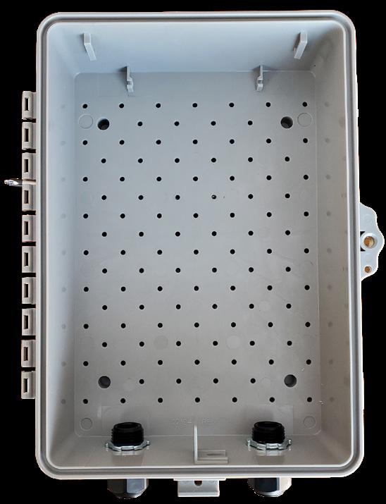

CraftSmart® Deploy Reel TAP Home Deployment Kit
Application
CraftSmart Deploy Reel TAP Home Deployment Kit (HDK) extends Clearfield’s field-proven fiber management expertise and leading-edge fiber connectivity performance all the way into the home. With the CraftSmart Deploy Reel TAP, the Home Deployment Kit packages the required patch cords, angled wall plate with SC adapter, and necessary SC adapter installation accessories in a single box. Truck rolls are minimized and customer turn-up is rapid. Choose the CraftSmart Deploy Reel TAP HDK for environments where plug-and-play along with internal slack storage are desired within the unit mounted outside the home.
The CraftSmart Deploy Reel TAP provides a secure demarcation point between the service provider network and the SFU. CraftSmart Deploy Reel TAP gives the network service provider both the ability to store slack fiber as well to provide a test access point (TAP) for ease of deployment and network maintenance without requiring access to the interior of the customer’s home. The FLEXdrop Deploy Reel mounts easily on the supplied pin, allowing 50 and 100 feet of pre-connectorized FLEXdrop riser cable to be deployed into the home. With the ability to accept a variety of drop cables, the CraftSmart Deploy Reel TAP can be wall- or pole-mounted, and can be integrated into any network architecture and deployment.
The wall plate is designed to attach to a singlegang outlet box. The angled design of the connection provides a low profile, natural strain relief.
This plate and snap-in module is available in white. The SC/APC adapter is included iwith the wall plate.
Integrity
• Industry standard SC adapter included
• Includes entrance points with integrated grommet Protection
• UV Stable Polycarbonate
• Screw latching system with lock hole Access

• Accepts 3mm cable, peelable flat drop and Small Form Factor FLATdrop Investment
• Allows testing and troubleshooting access without requiring the homeowner to be present
CraftSmart Angled Wall Plate
Integrity
• Industry standard SC/APC adapter included Protection
• Angle design Access
• Easy installation Investment
• No splice, clean, plug-and-play connection FieldShield FLEXdrop
Integrity
• Available in singlemode
• Supports all industry standard connectors
• Terminations designed, tested and certified to GR-326
• FLEXdrop fiber cable designed and tested to GR-20
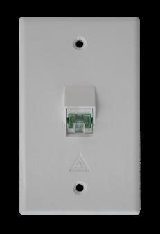
FieldShield ® FLEXdrop cable has an OSP-rated jacketing that allows for transition of FLEXdrop from the OSP environment directly into the inside plant, with the added benefit of being UL listed for riser applications. FLEXdrop can be used as a building wrap at turn-up, maximizing installation efficiency.
Protection
• UL listed for riser applications for single fiber only
• Passed UV testing and measurement standards per ASTM G155 for UL 1581
• Bend-insensitive (G.657.A2) fiber protects optical signal with minimal to zero attenuation down to a 10mm radius
• OSP-rated LSZH jacketing provides ruggedized protection for the patchcord or pigtail
• Staple-ready for walls, joists and around corners with Crown T-18 staples Access
• Standard color is black with an option for off-white
• Suitable for all types of indoor and outdoor implementations (duct required for aerial and direct bury) Investment
• Easy deployment allows capital investment to be aligned to customer take rates
CraftSmart Deploy Reel TAP
CraftSmart® Deploy Reel TAP Home Deployment Kit
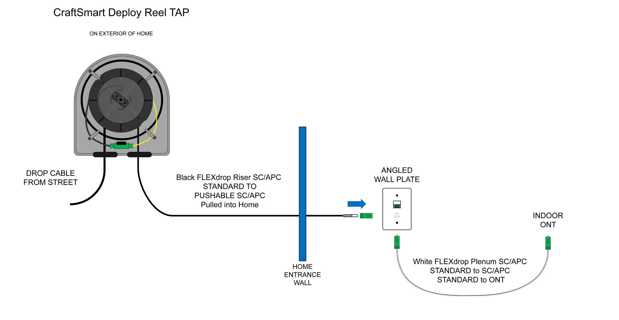
Technical Specifications
CraftSmart Deploy Reel TAP
Color Gray
Material UV Stabilized, Flame Retardant Polycarbonate
Adapter Style Receptacle SC/APC
Port Count 1
Seals Rubber Membrane Grommet (2)
Mounting Options Wall or Pole Mount
CraftSmart Angled Wall Plate
Dimensions 4.5” H x 2.76” W (114.3 mm H x 70 mm W)
Color White
Operating Temperature -4°F to 140°F (-20°C to 60°C)
Material ABS
Adapter Style Receptacle SC (included)
Adapter Slots 1 Angled
CraftSmart® Deploy Reel TAP Home Deployment Kit
FieldShield FLEXdrop
Fiber
Clad Diameter
Corning ® ClearCurve ® Optical Fiber or equivalent
125.0 ± 0.7 μm
Coating Diameter (Uncolored) 235 - 245 μm
Bend-Insensitive
Bend-Insensitive Fiber ITU G.657.A2
Color Code TIA/EIA 598
Fiber Count
Single
Pushable Connectors FieldShield SC/UPC and SC/APC
Standard Connectors SC/UPC and SC/APC
Mode
Singlemode
Internal Fiber Size 250 μm
Outside Diameter 0.118” (3 mm)
Color Black or white
Jacket Material Low Smoke Zero Halogen (LSZH)
Bend-Radius Standard to ITU G.657.A2 specifications
Installation Temperature -22°F to 131°F (-30°C to 55°C)
Operating Temperature -40°F to 176°F (-40°C to 80°C)
Installation Tension 20 lbf
Markings
Part number, lot number and footage markers every two feet (609.60 mm)
Cable Attenuation Spec 0.35 dB/km @ 1310 nm / 0.25 dB/km @ 1550 nm
Recommended Drop Length Available in 50 ft. and 100 ft. lengths
Home Deployment Kit Includes:
• CraftSmart Deploy Reel TAP
• CraftSmart Angled Wall Plate
• Black Entrance Cable: FLEXdrop Riser Pushable Fiber (Configurable adapter and lengths)
• White Equipment Cable: FLEXdrop Plenum Pushable Fiber (Configurable adapter and lengths)
CraftSmart® Deploy Reel TAP Home Deployment Kit
Pre-Configured Part Number
Part
HDK-HM1CC-CDR2F4CCFWA
HDK-HM1CC-CDR2F6CCFWA
HDK-HM1CC-CDR2WF4CCFWA
HDK-HM1CC-CDR2WF6CCFWA
Home Deployment Kit, Includes: Deploy Reel TAP Box; and Angled Wall Plate FLEXdrop (Black) Deploy Reel Reverse Flange Loaded with Standard Simplex SC/APC to Pushable SC/APC 50 Feet; FLEXdrop Equipment Cable (White): Standard Simplex SC/APC to Standard SC/APC 2 Meters, 1X Mounting Plate with SC/APC Adapter and Angled Wall Plate
Home Deployment Kit, Includes: Deploy Reel TAP Box; and Angled Wall Plate FLEXdrop (Black) Deploy Reel Reverse Flange Loaded with Standard Simplex SC/APC to Pushable SC/APC 100 Feet; FLEXdrop Equipment Cable (White): Standard Simplex SC/APC to Standard SC/APC 2 Meters, 1X Mounting Plate with SC/APC Adapter and Angled Wall Plate
Home Deployment Kit, Includes: Deploy Reel TAP Box; and Angled Wall Plate FLEXdrop (White) Deploy Reel Reverse Flange Loaded with Standard Simplex SC/APC to Pushable SC/APC 50 Feet; FLEXdrop Equipment Cable (White): Standard Simplex SC/APC to Standard SC/APC 2 Meters, 1X Mounting Plate with SC/APC Adapter and Angled Wall Plate
Home Deployment Kit, Includes: Deploy Reel TAP Box; and Angled Wall Plate FLEXdrop (White) Deploy Reel Reverse Flange Loaded with Standard Simplex SC/APC to Pushable SC/APC 100 Feet; FLEXdrop Equipment Cable (White): Standard Simplex SC/APC to Standard SC/APC 2 Meters, 1X Mounting Plate with SC/APC Adapter and Angled Wall Plate


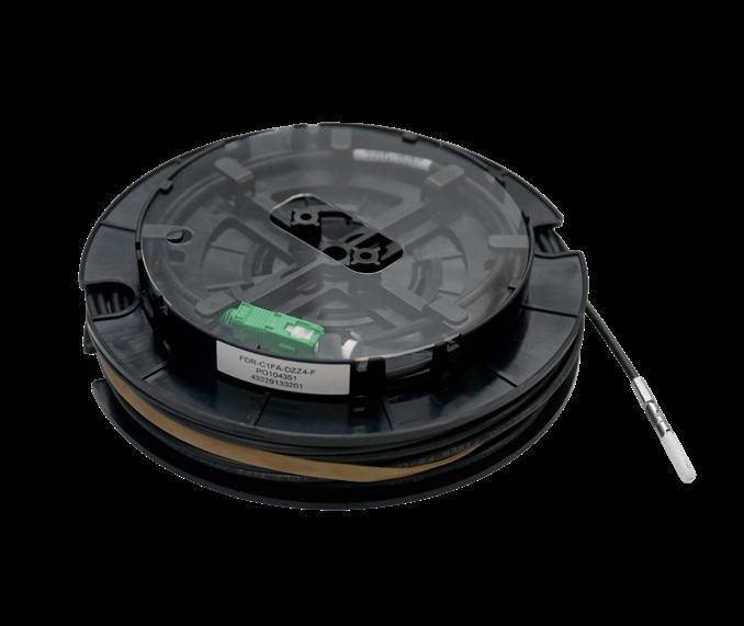
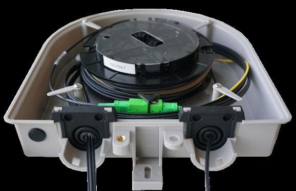
CraftSmart®
Angled Wall Plate
Application
The CraftSmart Angled Wall Plate allows for easy demarcation inside the premise for incoming feeder cable.
Description
The CraftSmart Angled Wall Plate can accommodate a single SC/APC connector. This small indoor faceplate offers a clean place to hold your home entrance cable. The angled design of the connection provides a low profile, natural strain relief. This plate and snap-in module is available in white. The SC/APC adapter is included with the wall plate.
Features and Benefits
Integrity
• Supports industry standard SC/APC adapters
Protection
• Angled design provides a safe place to house and connect SC/APC connector
Access
• Easy installation
• The wall plate is designed to attach to a single-gang outlet box
Investment
• No splice, clean, plug-and-play connection
Technical Specifications
CraftSmart Angled Wall Plate
Dimensions 4.5” H x 2.76” W (114.3 mm H x 70 mm W)
Color White
Operating Temperature -4°F to 140°F (-20°C to 60°C)
Material ABS
Adapter Style Receptacle SC/APC Included
Adapter Slots 1 Unit, Angled
Pre-Configured Part Numbers
Part Number Description

024042 Kit, Single Port Angled White Faceplate with SC/APC Adapter, Includes White Keystone Coupler and Wall Plate Screws
CraftSmart ®
Deploy Reel TAP
Application
Engineered to land FTTH terminations as conveniently as possible, the CraftSmart Deploy Reel TAP is optimized for delivery of FieldShield ® FLEXdrop ® via a FLEXdrop Deploy Reel. The lockable enclosure is curved, making it ideal for a variety of cable applications, including our small form factor (SFF) drop cable when entering the box. Up to 50 feet of SFF can be easily stored.
Description
The CraftSmart Deploy Reel TAP offers single count fiber deployment in a discreet footprint and without sacrificing proper fiber management. The CraftSmart Deploy Reel TAP is designed to make FTTH more cost-effective and efficient than previously thought possible. Standardizing on a craft-friendly, building block architecture reduces the operating costs of fiber deployments by reducing installation times and inventory carrying requirements.
Features
and Benefits
Integrity
• UV Stabilized
• Designed specifically to house the FLEXdrop Deploy Reel
• Deploy Reel mounting plate included with box
Protection
• Two positions for splice sleeve
• Includes SC/APC adapter
• Ground lug can be ordered separately
Access
• Mounting plate accepts the deploy reel mounting pin
• Box is easy to install with both internal and external mounting holes
• Two bottom entry/exit points utilizing multifunctional gaskets
Investment
• Holds up to 100 feet of FLEXdrop on Deploy Reel
• Surface- or pole-mount capable
• Flame retardant PVC for durability
Technical Specifications
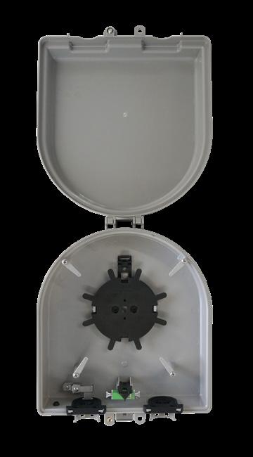

CraftSmart ® Deploy Reel TAP
Pre-Configured Part Numbers
Part Number
FDRH-CDR2-GGZG-NRF
FDRH-CDR4-GGZG-NRF
FDRH-CDRW2-GGZGNRF
FDRH-CDRW4-GGZGNRF
Description
Deploy reel kit, includes Deploy Reel TAP Wall Box, FLEXdrop riser black 3mm, Deploy Reel loaded with SC/APC adapter and simplex SC/APC to pullable SC/APC 50 feet (narrow width, opposite spooling), Deploy Reel Mounting Plate with SC/APC adapter, left and right grommet
Deploy reel kit, includes Deploy Reel TAP Wall Box, FLEXdrop riser black 3mm, Deploy Reel loaded with SC/APC adapter and simplex SC/APC to pullable SC/APC 100 feet (narrow width, opposite spooling), Deploy Reel Mounting Plate with SC/APC adapter, left and right grommet
Deploy reel kit, includes Deploy Reel TAP Wall Box, FLEXdrop riser white 3mm, Deploy Reel loaded with SC/APC adapter and simplex SC/APC to pullable SC/APC 50 feet (narrow width, opposite spooling), Deploy Reel Mounting Plate with SC/APC adapter, left and right grommet
Deploy reel kit, includes Deploy Reel TAP Wall Box, FLEXdrop riser white 3mm, Deploy Reel loaded with SC/APC adapter and simplex SC/APC to pullable SC/APC 100 feet (narrow width, opposite spooling), Deploy Reel Mounting Plate with SC/APC adapter, left and right grommet
Ready Connect Terminal
Application
The Ready Connect Terminal (RCT) is a splice terminal designed for pedestal applications. Optimized for above-ground, distributed TAP and distributed split architectures and enabled with multiple FBT and PLC splitter options, this craft-friendly terminal delivers up to eight drops when mid-spanning is required. Drop cables can be pre-terminated or spliced.
Description
The Ready Connect Terminal is a small, breathable terminal that allows for mid-spanning, splicing, and terminations with optical components. Delivering Clearfield’s commitment to craft-friendly solutions, the terminal features a removable splice tray for easy access when technicians are splicing up to 24 loose tube splices, in addition to a modular, removable adapter plate for terminal applications that provides easy access for adapter cleaning.
Meeting the demand for small, economical solutions, the small form factor allows for mounting in Clearfield’s extremely compact CraftSmart ® FiberFirst 6-inch Pedestal, offering homeowners a discreet, aesthetically pleasing option for FTTH deployments.
Features and Benefits
Integrity
• Designed for configuration flexibility - splicing, pigtails or splitters
• Designed for mid-span applications
Protection
• Manufactured with TRISTAR Polycarbonate plastic for impact and flame retardant
• Lay in grommet for environmental protection
Access
• Removable cover for easy access
• Removable splice tray allows easy fiber routing
• Removable adapter plate for easy cleaning and scoping
• Removable splice tray for mid-spanning and drop terminations
Investment
• Providing a small economical solution for the provider
• Designed in flexibility for use as a terminal or splice enclosure

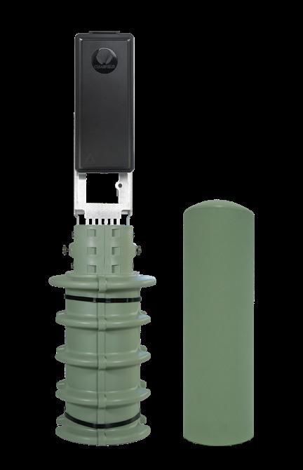
StreetSmart® Ready Connect Terminal
Technical Specifications
StreetSmart Ready Connect Terminal
Dimensions
Terminal Options
Number of Splitters
11.30”(H) x 4.70”(W) x 2.00”(D) (287.02mm x 119.38mm x 50.8mm)
Mid-spanning, plug-and-play, splicing, optical components enabled
Supports up to (3) FBT splitters and up to (3) PLC splitters
Material Manufactured with TRISTAR Polycarbonate plastic for impact and flame retardant
Output Connector SC/APC, SC/UPC
Number of Drops or Distribution Ports
Supports up to 8 drops
Cable Entrance Lay in grommet with internal strain relief
Labeling Designation label on door
Mounting Options
Above ground only in a pedestal or on an interior wall
Mid-Span - Splice Only (No Adapter or Pigtails)
Description
Ready Connect Terminal, empty, includes splice chip, NO fibers, NO adapters, 100% splice
Ready Connect Terminal (RCT)-Mid-Span with splice drops. NO pigtails or NO adapters
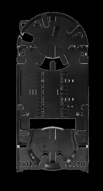

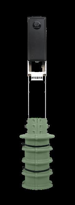
Pre-Configured Part Numbers - RCT
Part Number Description
RCT-00Z-ZZZ-ZZZ Ready Connect Terminal, empty, includes splice chip, NO fibers, NO adapters, 100% splice
Pre-Configured Part Numbers - Empty Pedestals*
CFP-0630-EMPTY-BACK 30 inch tall, 6” diameter pedestal with installed backplane for slack storage for mounting RCT box
CFP-0620-EMPTY-BACK 20 inch tall, 6” diameter pedestal with installed backplane for slack storage for mounting RCT box
* Does not include box
StreetSmart Ready Connect Terminal
Mid-Span - With Pigtails and Adapter (NO Splitter)
Description
Ready Connect Terminal, includes installed pigtails and adapter pack
Ready Connect Terminal (RCT)-Mid-Span with terminated drops.
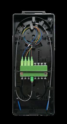

Configured Part Numbers
Example: RCT-08C-ZY8-ZZZ = Ready Connect Terminal loaded with
Pre-Configured
Part Numbers - Empty Pedestals*
Does not include
StreetSmart®
Ready Connect Terminal
Mid-Span - Splitter with Adapter Pack
Description
Ready Connect Terminal, includes installed splitter and adapter pack
Ready Connect Terminal (RCT)-Mid-Span with Splitter and terminated drops

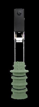
Configured Part Numbers
Example: RCT-08C-ZZZ-5ZZ = Ready Connect Terminal with 1x8 splitter with SC/APC drops and splice input.
Pre-Configured Part Numbers - Empty Pedestals*
CFP-0630-EMPTY-BACK
CFP-0620-EMPTY-BACK
* Does not include box
SeeChange®
Terminal
Application
The SeeChange Terminal is Clearfield’s small, carrier grade plug-and-play access terminal for use in FTTx applications, including Fiber to Home and Fiber to Business. It’s small size also makes it an attractive choice to deliver fiber to cell towers and inside 5G decorative poles. The terminal provides an interface between incoming feeder fiber and single fiber drop cables.
Description
The SeeChange Terminal is fully sealed and includes a multifiber MPO input port, 2 or 4 single fiber drop ports and a multifiber MPO express output port. The MPO express output port is used to daisy chain to other SeeChange terminals deeper in the neighborhood. All connections to the terminal are made using SeeChange hardened connectors that can be installed with entry level technicians for quick deployment. SeeChange hardened connectors are ruggedized for OSP applications and meet Clearfield’s FiberDeep performance levels for low insertion loss (0.2dB max IL for single fiber and 0.35dB max IL for MPO assemblies). Both centralized split and distributed split configurations are supported by the SeeChange Terminal. The terminal can be deployed below grade in vaults, handholes and flower pots, as well as above grade in pedestals or on a pole, and can be hung overhead on a strand for aerial applications.
Features and Benefits
Integrity
• SeeChange Terminal GR-771 Compliant
• Hardened SeeChange Connectors GR-3120 and GR-3152 compliant
• Supports SeeChange MPO and SeeChange SC/APC connectors
Protection
• Environmentally sealed for the harshest OSP environments
• Molded with UV resistant thermoplastic material
• Above grade, below grade and aerial mounting options
• Carrier grade GR compliant terminal and connectors
Access
• 1 SeeChange MPO input port
• 2 or 4 SeeChange SC APC drop ports
• 1 SeeChange MPO express output port
• Compact footprint reduces space in handholes and pedestals
Investment
• Strategic configurations to reduce inventory and shorten lead times
• Repeatable design reduces engineering time
• Plug-and-play connections speed installations
• Centralized and distributed split configurations available
• Supports FTTx or 5G cellular application


SeeChange® Terminal
Technical Specifications
SeeChange Terminal
Dimensions 3 x 4 x 5.5” (83.8mm x 111.8mm x 139.7mm)
Mounting Options
Below Grade: handhole or flowerpot, Above Grade: Pole or Pedestal with mounting bracket, Aerial: Strand mount with Deltec strap and spacers
Material Black UV Resistant Thermoplastic
Input Port (1) SeeChange 14 mm MPO
Drop Ports (2) or (4) SeeChange 14 mm SC/APC
Output Express Port (1) SeeChange 14 mm MPO Weight

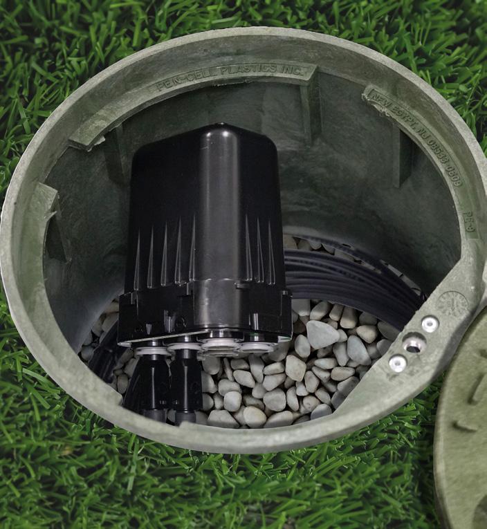
Below Grade vault, hand hole or flowerpot
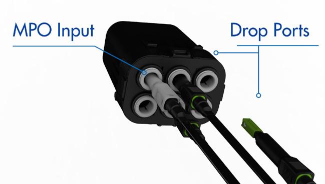

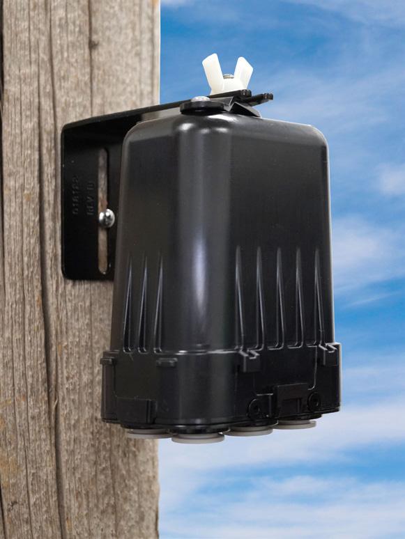
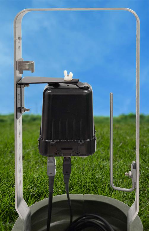
Above grade pedestal and pole mount

pedestal
Aerial on a strand with Deltec strap
SeeChange® Terminal
SeeChange Terminal - Centralized Split Applications
SeeChange Terminals can be configured to support centralized split Fiber to the Home (FTTH) architectures. To simplify engineering, the same 4 port SeeChange Terminal can be deployed in a daisy chain configuration where three terminals are combined in series to feed up to 12 homes. This simple to follow daisy chain practice can be repeated for all homes in a serving area.


Configured Part Numbers
* This configuration can be used as an end terminal in a daisy chain configuration or as a stand-alone drop terminal for Fiber to the Home, Business or 5G Smartpole applications
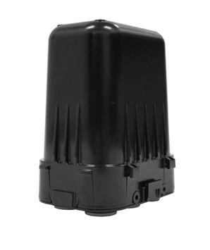
SeeChange® Terminal
MPT Terminal - Centralized Split Applications
In centralized split applications, the MPT Terminal can be deployed between the FDH splitter cabinet and SeeChange Terminals. Rather than home running SeeChange Terminals back to the FDH cabinet, the MPT acts as a consolidation point for clusters of SeeChange Terminals in a neighborhood. The MPT is configured with either a 24, 48, 72 or 96 fiber cable stub which is routed to the FDH cabinet.

Configured Part Numbers
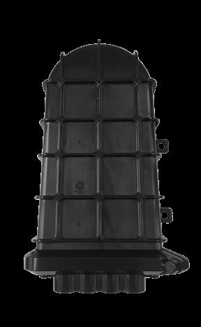
SeeChange® Terminal
SeeChange Terminal - Distributed Split Applications
SeeChange Terminals can be configured to support distributed split Fiber to the Home (FTTH) architectures. To simplify engineering, the same 4 port SeeChange terminal can be deployed in a daisy chain configuration where four terminals are combined in series to feed up to 16 homes. This simple to follow daisy chain practice can be repeated for all homes in a serving area.
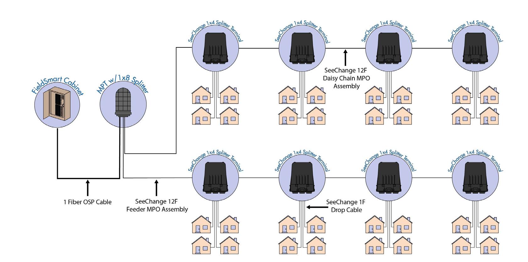
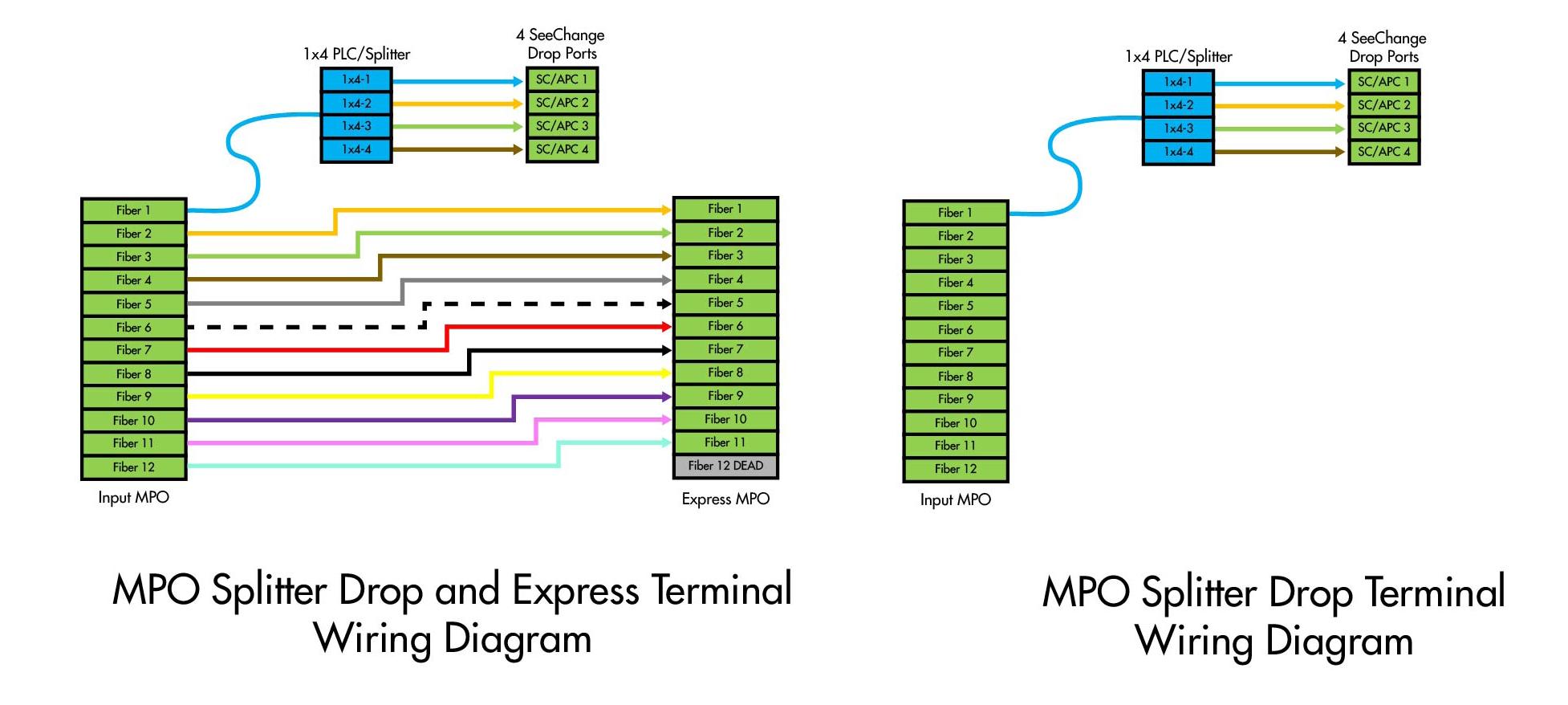
Configured Part Numbers
MPO Drop and Express
MPO Drop*
SeeChange Terminal with (1) 12F SeeChange MPO input port, 1x4 Splitter, 4 SeeChange SC APC drop ports, (1) 12F SeeChange MPO express output port
SCT-M5-02CEZZ-115 SCT-M5-04C-8ZZ-115
SeeChange Terminal with (1) 12F SeeChange MPO input port, 1x4 Splitter, 4 SeeChange SC APC drop ports SCT-M5-02C-EZZ
* This configuration can be used as an end terminal in a daisy chain configuration or as a stand-alone drop terminal for Fiber to the Home, Business or 5G Smartpole applications.
SeeChange® Terminal
MPT Terminal - Distributed Split Applications
In distributed split applications, the MPT Terminal can be deployed between the Central Office OLT and SeeChange terminals. A single fiber is routed to the input of the MPT where it is spliced to a 1x8 splitter. The outputs of the splitter are wired internally to MPO output ports. The MPT acts as a consolidation point for clusters of SeeChange Terminals in a neighborhood.
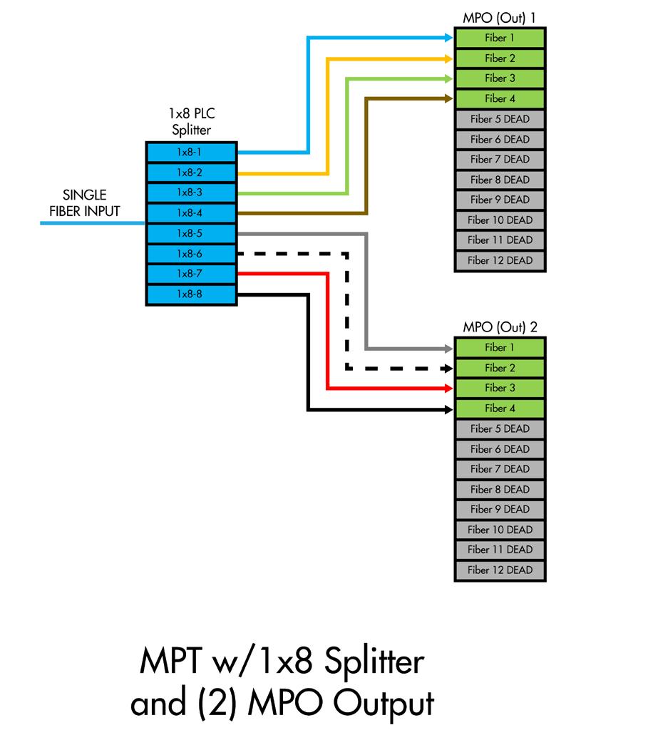
Pre-Configured Part Numbers
Part
MPT-085-Z1F-5ZS-01
MPT-085-Z1F-5ZH-01
Interface between Central Office OLT and SeeChange Terminals
Interface between Central Office OLT and SeeChange Terminals
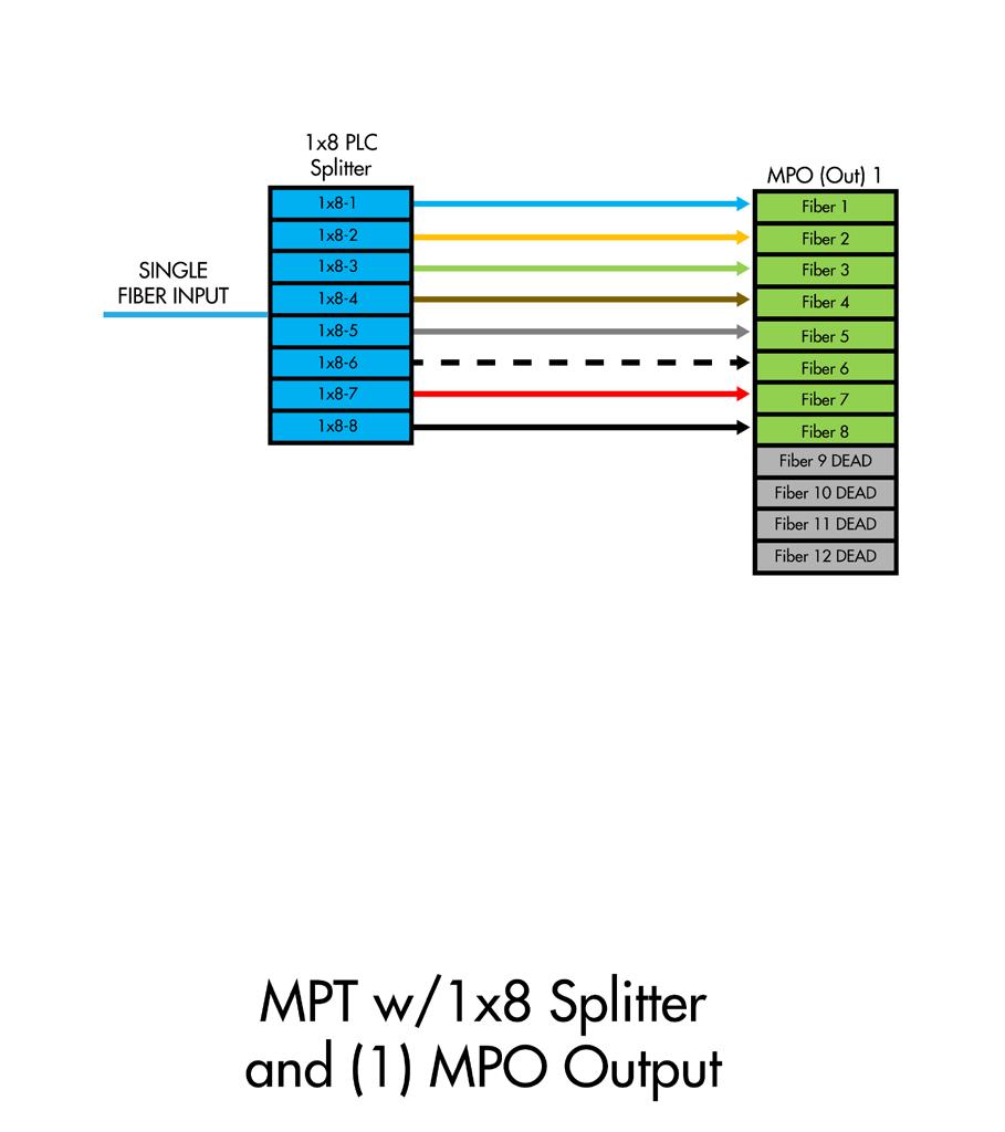
MPT loaded with (1) 1 x 8 splitter. Single input fiber is spliced to internal splitter with (2) 4 fiber MPOs output ports
MPT loaded with (1) 1 x 8 splitter. Single input fiber is spliced to internal splitter with (1) 8 fiber MPO output port
SeeChange® Terminal
SeeChange Assemblies
SeeChange Hybrid Drop Assemblies
Single Fiber SeeChange Hybrid Drop Assemblies are used between drop ports on the SeeChange Terminal and the NID (Network Interface Device) or TAP box at the home. One end of the assembly is terminated with the SeeChange SC APC connector. The opposite end is terminated with a FieldShield pushable SC APC connector which can be pulled inside a conduit direct buried or hung aerially. SeeChange Hybrid Drop Assemblies are available with FieldShield Small Form Factor (SFF) FLATdrop 900µm peelable cable. Standard lengths of 100, 150, 200, 250, 300, 350, 400, 450 and 500 feet long and can be ordered with or without a tone wire. SeeChange Drop Assemblies are also available with a stub or blunt end at the house when a field installable connector is used or the drop is spliced to a pigtail.
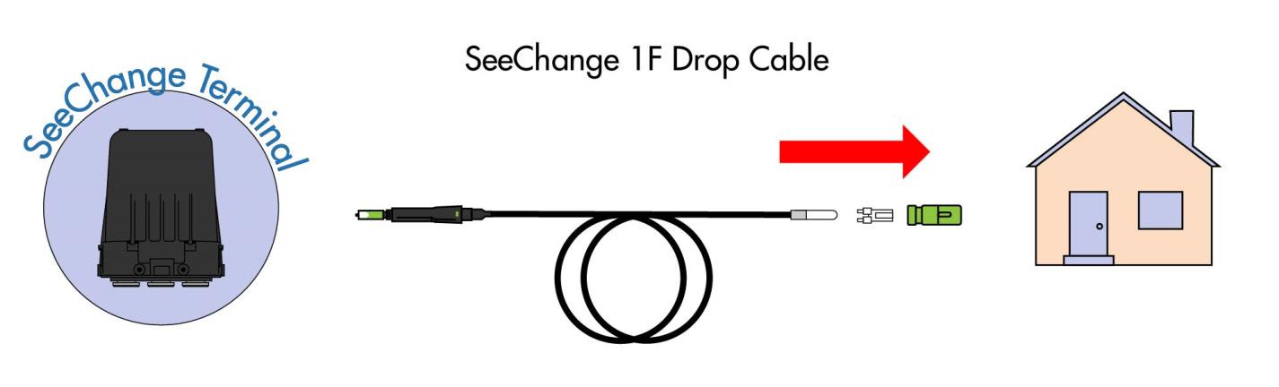
Configured Part Numbers
SeeChange Drop Cables are available in standard lengths of 100, 150, 200, 250, 300, 350, 400, 450 and 500 feet.
SFF Pushable SC Pulling Bullet

The SC/APC end of the drop cable is protected during installation with a bullet case and eye loop with string. The pull string eye loop is rated for 50 lbs. maximum pull force. When using the FS-PUL-5-9-MM pulling sock accessory, the rated maximum force is 100 lbs. The minimum recommended conduit size for SeeChange Hybrid Drop Assemblies is ¾” diameter.

SFF Cable Bullet Case Pull String Locking Ring
SeeChange® Terminal
SeeChange Daisy Chain Assemblies
Twelve Fiber SeeChange Daisy Chain Assemblies are used between two SeeChange Terminals when expressing output fibers from one terminal to the input of the other terminal. Both ends of the assembly are terminated with SeeChange MPO connectors. SeeChange MPO Daisy Chain Assemblies are available with conventional 12 fiber flat drop cable. Standard lengths of 100, 150, 200, 250, 300, 400 and 500 feet long and can be ordered with or without a tone wire. The minimum recommended conduit size for SeeChange Daisy Chain Assemblies is 1 ¼” diameter.

Configured Part Numbers
12F Flat Drop SeeChange MPO SeeChange MPO
SeeChange MPO Daisy Chain Cable Assemblies are available in
xxxxF
SeeChange® Terminal
SeeChange Hybrid MPO Feeder Assemblies
12 Fiber SeeChange Hybrid MPO Feeder Assemblies are used between a YOURx Multi-Purpose Terminal (MPT) and a SeeChange Terminal. One end of the assembly is terminated with a SeeChange MPO connector. The opposite end is terminated with a 12 fiber pushable MPO to connect into the ports of the MPT terminal. SeeChange Hybrid MPO Feeder Assemblies are available with conventional 12 fiber flat drop cable. Standard lengths of 100, 150, 200, 250, 300, 400 and 500 feet long and can be ordered with or without a tone wire.
For some applications, the SeeChange Terminal feeder cable is spliced directly into the network in place of routing to an MPT terminal. In this situation, the SeeChange MPO feeder will be terminated with a SeeChange MPO connector on one end with no connector on the other end.
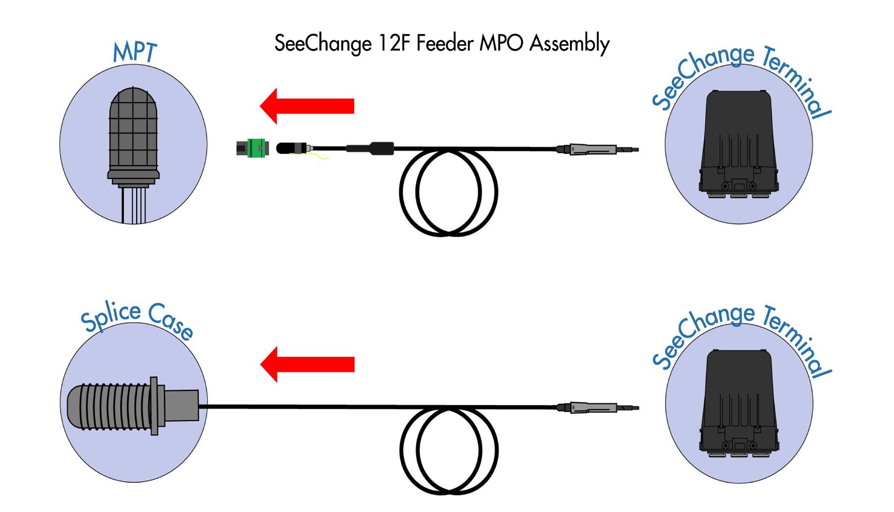
Configured Part Numbers
Pushable MPO to SeeChange MPO Cables are available in standard lengths of 100, 150, 200, 250, 300, 400 and 500 feet
SeeChange® Terminal - Accessories
Accessory
Terminal Mounting Bracket
SCT-MTGBRACKET
Terminal L-Mounting Bracket, plate and wing nut for pole, wall or pedestal mount
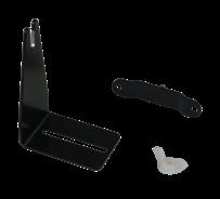
Aerial Mounting Clip
SeeChange Connector Cleaning Kit
SCT-AERBRACKET
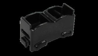


SeeChange® Terminal - Accessories
Accessory
Pull Sock MPO Cables
SEE-PULLINGSOCK
Pulling sock for SeeChange MPO connectors, 50 lb. max. pull force
Protection Sleeve Kit
SeeChange SC Test Cable
SeeChange MPO Test Cable
SeeChange MPO Breakout Test Cable
SeeChange TerminalFlower Pot
SEE-CONNPROTECT-10 (10)reusable protective microduct sleeve to cover connector ends during installation
SEE-TESTSCAPCSEESCAPC-2F
SEE-TEST-MPOSEEMPO-2F
SEE-TEST-SCAPCSEEMPO-2F
Test cable, SeeChange SC/APC to standard SC/APC, 2 feet long

Test cable, SeeChange MPO female to standard MPO Female, 2 feet long
Test cable, SeeChange MPO female to 12 standard SC APC connectors, 2 feet long
SeeChange®
Hardened Fiber Assemblies
Application
SeeChange Hardened Fiber Assemblies are used to make connections to Clearfield’s SeeChange Access Terminals in FTTx applications including Fiber to the Home and Fiber to the Business. The assemblies provide a means of connecting multi-fiber cables between terminals or single fiber drop cables from a SeeChange Terminal to a home or business.
Description
SeeChange Hardened Fiber Assemblies are available with either a multi-fiber MPO connector or a single fiber SC APC connector. An integrated rear shell provides the feature that engages and fully seals a connection to a SeeChange Terminal FlexPort. The connection is ideal for harsh OSP environments and is rated for installations below grade or above grade including aerial installations on strands. Both connector styles are easily pushed into open terminal ports without any tools, making it a perfect for quick installations using entry level technicians. Single Fiber SeeChange Hardened Drop Cables are configured with a pushable SC APC connector on one end, allowing for placing and pushing through a conduit, in addition to the traditional deployments of direct bury or placing aerially.

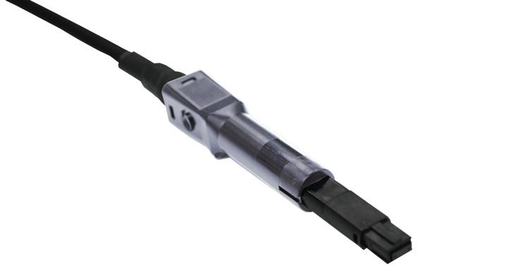
SeeChange Hardened Fiber Assemblies meet Clearfield’s FiberDeep performance levels for low insertion loss (0.2dB max IL for single fiber and 0.35 max IL for MPO assemblies). Rigorous carrier grade testing has been performed on both connector styles ensuring optimal system performance long into the future.
SeeChange hardened single fiber drop assemblies are available with FieldShield Small Form Factor (SFF) FLATdrop 900µm peelable subunit. SeeChange MPO Assemblies are manufactured using industry standard multifiber flat drop cable. All SeeChange cable assemblies are available with or without a tone wire.
FieldShield Small Form Factor FLATdrop 900μm Peelable is a uniquely smaller footprint flat drop solution for the access portion of a FTTH or FTTB network. The small format handles more easily than traditional flat drop, allowing for less coiled storage space in outdoor storage. When the jacket is snipped and easily peeled away, the exposed 900μm subunit stores neatly on the compact FieldShield slack reel.
Features and Benefits
Integrity
• SeeChange Connectors are GR-3120 and GR-3150 compliant
• SeeChange Cables are GR-20 compliant
• FiberDeep ensures low Insertion Loss (0.2 dB max SC APC, 0.35 max MPO)
Protection
• SeeChange Assemblies provide an air-tight, water-tight connections when plugged into SeeChange terminal FlexPorts
• Molded with UV resistant thermoplastic material
• Connectors rated for above grade, below grade and aerial mounting conditions
Access
• Connectors are keyed for easy push on installation
• 8” SFF cable coil diameter reduces space in handholes and pedestals
• Toneable cable options provide for traceability
SeeChange® Hardened Fiber Assemblies
Investment
• Strategic configurations to reduce inventory
• Plug and Play connections speed installations
• SeeChange Hardened Cable Assemblies are carrier grade
Technical Specifications
Connector Styles
SeeChange SC/APC or Pushable SC/APC SeeChange MPO or Stub/Pigtail
SeeChange® Hardened
Fiber Assemblies
SeeChange Assemblies
SeeChange Hybrid Drop Assemblies
Single Fiber SeeChange Hybrid Drop Assemblies are used between drop ports on the SeeChange Terminal and the NID (Network Interface Device) or TAP box at the home. One end of the assembly is terminated with the SeeChange SC APC connector. The opposite end is terminated with a FieldShield pushable SC APC connector which can be pulled inside a conduit direct buried or hung aerially. SeeChange Hybrid Drop Assemblies are available with FieldShield Small Form Factor (SFF) FLATdrop 900µm peelable cable. Standard lengths of 100, 150, 200, 250, 300, 350, 400, 450 and 500 feet long and can be ordered with or without a tone wire. SeeChange Drop Assemblies are also available with a stub or blunt end at the house when a field installable connector is used or the drop is spliced to a pigtail.
Configured Part Numbers
SeeChange Drop Cables are available in standard lengths of 100, 150, 200, 250, 300, 350, 400, 450 and 500 feet.
SFF Pushable SC Pulling Bullet
The SC/APC end of the drop cable is protected during installation with a bullet case and eye loop with string. The pull string eye loop is rated for 50 lbs. maximum pull force. When using the FS-PUL-5-9-MM pulling sock accessory, the rated maximum force is 100 lbs. The minimum recommended conduit size for SeeChange Hybrid Drop Assemblies is ¾” diameter.
SFF Cable Bullet Case Pull String Locking Ring Scan for Pulling Bullet Video.
SeeChange® Hardened Fiber Assemblies
SeeChange Daisy Chain Assemblies
Twelve Fiber SeeChange Daisy Chain Assemblies are used between two SeeChange Terminals when expressing output fibers from one terminal to the input of the other terminal. Both ends of the assembly are terminated with SeeChange MPO connectors. SeeChange MPO Daisy Chain Assemblies are available with conventional 12 fiber flat drop cable. Standard lengths of 100, 150, 200, 250, 300, 400 and 500 feet long and can be ordered with or without a tone wire. The minimum recommended conduit size for SeeChange Daisy Chain Assemblies is 1 ¼” diameter.
Configured Part Numbers
Conventional 12F Flat Drop SeeChange MPO SeeChange MPO SEE-U1-012-62ZZ-62ZZ xxxxF SEE-T1-012-62ZZ-62ZZ xxxxF
SeeChange MPO Daisy Chain Cable Assemblies are available in standard lengths of 10, 100, 150, 200, 250, 300, 400 and 500 feet.
SeeChange® Hardened Fiber Assemblies
SeeChange Hybrid MPO Feeder Assemblies
12 Fiber SeeChange Hybrid MPO Feeder Assemblies are used between a YOURx Multi-Purpose Terminal (MPT) and a SeeChange Terminal. One end of the assembly is terminated with a SeeChange MPO connector. The opposite end is terminated with a 12 fiber pushable MPO to connect into the ports of the MPT terminal. SeeChange Hybrid MPO Feeder Assemblies are available with conventional 12 fiber flat drop cable. Standard lengths of 100, 150, 200, 250, 300, 400 and 500 feet long and can be ordered with or without a tone wire.
For some applications, the SeeChange Terminal feeder cable is spliced directly into the network in place of routing to an MPT terminal. In this situation, the SeeChange MPO feeder will be terminated with a SeeChange MPO connector on one end with no connector on the other end.
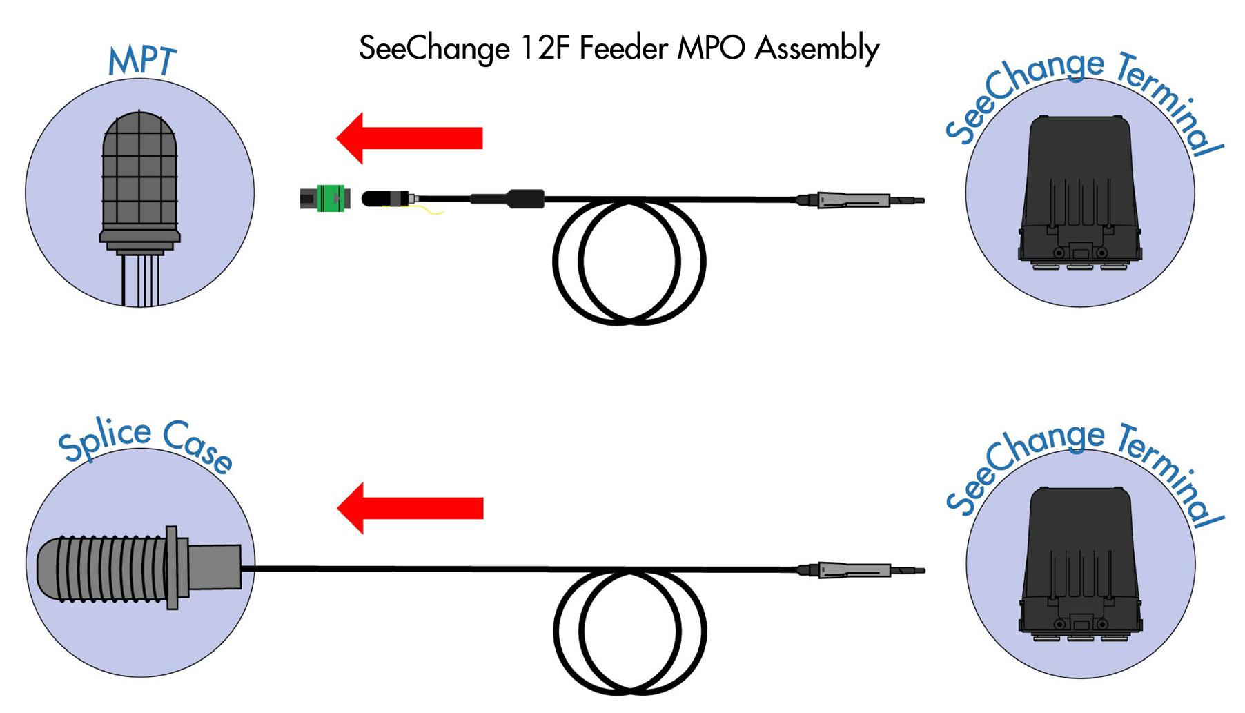
Configured Part Numbers
Pushable MPO to SeeChange MPO Cables are available in standard lengths of 100, 150, 200, 250, 300, 400 and 500 feet
SeeChange® Hardened Fiber Assemblies - Accessories
SeeChange Connector Cleaning Kit SCT-CLEANINGKIT
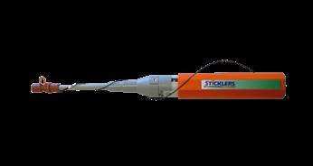


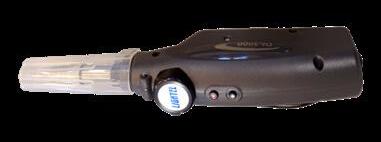


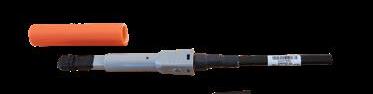
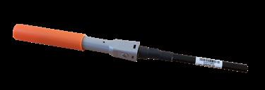
SeeChange® Hardened Fiber Assemblies - Accessories
Accessory Part Number
SeeChange SC Test Cable
SeeChange MPO Test Cable
SeeChange MPO Breakout Test Cable
SEE-TESTSCAPCSEESCAPC-2F
SEE-TEST-MPOSEEMPO-2F
SEE-TEST-SCAPCSEEMPO-2F
Test Cable, SeeChange SC/APC to standard SC/APC, 2 feet long

Test Cable, SeeChange MPO female to standard MPO Female, 2 feet long
Test Cable, SeeChange MPO female to 12 standard SC APC connectors, 2 feet long

YOURx ® Multi-Purpose Terminal (MPT)
Application
Designed for network design flexibility, Clearfield’s YOURx Multi-Purpose Terminal (MPT) is optimized for deployments requiring mid-span, fiber drop, splitter or optical component capabilities.
Description
The YOURx Multi-Purpose Terminal is a sealed mid-span terminal that will accept cables with a diameter up to 0.7” (17.78mm). The terminal includes eight individual sealed distribution drops with removable tabs - all air and water-tight via YOURx FlexPort technology. The snap-in splice chip will support 12 loose tube splices or 3 mass fusion (36 fibers) splices, with the ability to store up to 8 feet per buffer tube. The terminal cable entry point uses a split sleeve grommet design for easy installation. The slide out adapter plate allows installers easy access for cleaning or testing connectors, if required. The bulkhead allows for mounting of optical components, splitters, WDMs and DWDMs. When accessing the terminal, a standard can wrench is the only tool required. The terminal can be deployed above grade, below grade, on a pole mount, or in an aerial mount.
Features and Benefits
Integrity
• Designed, tested and certified to Telcordia GR-771
• SC and LC Terminations designed, tested and certified to Telcordia GR-326
• MPO Terminations designed, tested and certified to Telcordia GR-1435

• Supports pre-terminated FieldShield FLATdrop, FLEXdrop, StrongFiber or Pushable Fiber assemblies for drops
Protection
• Optimized for use with FieldShield Microduct or FlexConnector
• FlexConnector provides bend-limiting, strain-relief protection and water-tight seal
• Black UV resistant thermoplastic design to resist corrosion
• Environmentally sealed terminal providing maximum reliability and durability in the harshest OSP environments
Access
• Fieldshield Pushable Fiber, FieldShield FLATdrop and round cable. (IMPORTANT - Be sure to select the correct grommet!)
• Splicing or plug-and-play configuration
• Optical component solution maximize existing architectures or relief from exhausted fiber scenarios
Investment
• Modular design allows replacement of bulkhead or face plate in case where damage has occurred
• Flexibility in configuration provides designing network easier, utilizing the same terminal
• Using the patch only stub design allows speed to deployment in plug-and-play design
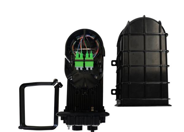


Patch Only
Patch and Splice
YOURx ®
Multi-Purpose
Terminal (MPT)
Technical Specifications
YOURx Multi-Purpose Terminal (MPT)
Dimensions
Mounting Options
12.44”L x 6.76”W x 5.49”H (315.97 mm x 171.70 mm x 139.44 mm)
Below Grade — Vaults - V5A-AZP (17” x 30” x 24”) or V6A-AZP (24” x 36” x 24”)
Above Ground — Pedestals - FPP-8820 (8” x 8” with 12” high base), FPP-101020 (10” x 10” with 20” high base) or FPP-121230 (12” x 12” with 30” high base)
Pole or Aerial/Strand
Internal Slack 8’ of 12 fiber buffer tube; Total 48’ of 3 mm
Feeder Cable Accepts cable diameter of up to .70” (17.78 mm) IMPORTANT - Be sure to select correct grommet
Distribution Ports Eight 14 mm ports; ports are designed to accept FieldShield FlexConnector
Connector Types SC/APC, SC/UPC, LC/APC, LC/UPC and MPO Duplex
Material Black UV Resistant Thermoplastic
Weight 4 lbs.
Application: Mid-Span with Spliced Drops (No Connectors, No Adapters)
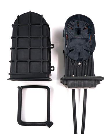
3 Select Grommet for Incoming Cable
H = Round Cable (0.45 to 0.70" diameter)
S = FieldShield Pushable Fiber, FLATdrop, or round cable (.44" or less)
* IMPORTANT- Be sure to select correct grommet
YOURx ®
Multi-Purpose Terminal (MPT)
Application: Mid-Span With Patch and Splice Drops
Select

A = Aerial (Included)
P = Pole Mount (Included)
S = Pedestal (Included)
Z = No Bracket
H = Round Cable (0.45 to 0.70" diameter)
S = FieldShield Pushable Fiber, FLATdrop, or round cable (.44" or less)
* IMPORTANT- Be sure to select correct grommet
Splitter Option with Connectorized Drops
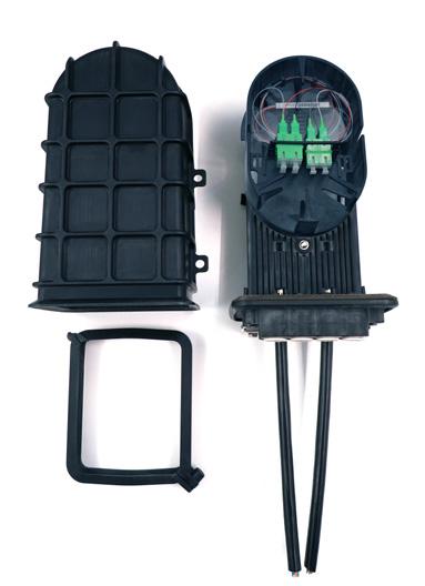
Select Mounting Bracket
Bracket
H
S
*
YOURx ®
Multi-Purpose Terminal (MPT)
Application: Mid-Span Splitter Option with Spliced Drops (No Connectors, No Adapters)
1. Order Empty Terminal
2. Order Splitter (Unterminated)

3 Select Grommet for Incoming Cable
H = Round Cable (0.45 to 0.70" diameter)
S = FieldShield Pushable Fiber, FLATdrop, or round cable (.44" or less)
* IMPORTANT- Be sure to select correct grommet

Application: WDM or DWDM with Mid-Span — Business Class
WDM or DWDM = Contact Clearfield for correct configurations at 1-800-422-2537
YOURx ®
Multi-Purpose Terminal (MPT)
020996
021263
MPT-PED-BRACKET
Grommet for Round Cable OD 0.45 to 0.70”
IMPORTANT- Be sure to select correct grommet
Grommet for Flat, FieldShield or Round Cable with OD 0.44” or less
IMPORTANT- Be sure to select correct grommet
Supports pedestal and vault mounting.
Pedestal Mounting: Will mount in FPP-8820, FPP-101020, FPP121230
MPT-AER-BRACKET
MPT-PWD-BRACKET
FS-FIFC-103-6PAK
FS-FIFC-143-6PAK
FSH-FIFC-4PAK
Aerial Mounting: Bug nuts included. When assembled height is 10.00”.
Supports pole (wood and metal) and wall
* For metal pole applications, order Hose Clamp Straps (P/N 013034) sold separately
Field Installable FlexConnector, 10mm Port, 3mm Cable, Black Grommet, 6 Pack (FLEXdrop and FieldShield)
Field Installable FlexConnector, 14mm Port, 3mm Cable, Black Grommet, 6 Pack, Required for Pushable MPO
Field Installable FlexConnector, 10mm, 3mm Cable (FLATdrop)
MPT-GROUNDING-01 Grounding Kit
MPT-BONDING-01 Bonding Kit
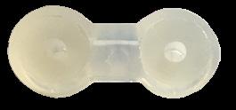
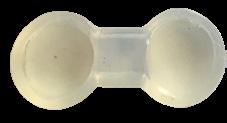


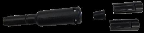
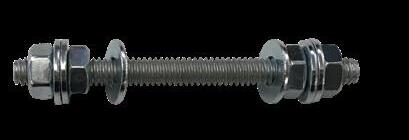
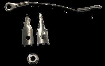
YOURx ®
YOURx-Terminal
Application
The YOURx-Terminal improves the customer application and craft-experience by providing an access terminal capable of 16 drops, two feeder ports for mid-span and daisy-chaining scenarios, along with a fully protected and restorable pathway from the YOURx-Terminal to the YOURx-TAP using the Clearfield ® design methodology of a modular and flexible approach that scales across the application environment.
Description
The YOURx-Terminal provides up to sixteen drops ports along with two 10mm feeder ports and two 14mm feeder ports – all air/water tight via YOURx FlexPort technology and accepting all industry standard connectors. The modular approach of the YOURx-Terminal comes in the removable, configurable FlexCartridge. Configure the fiber ports to meet the deployment application, then if future requirements change, remove the FlexCartridge and snap in a replacement – without any disruption to the base unit.
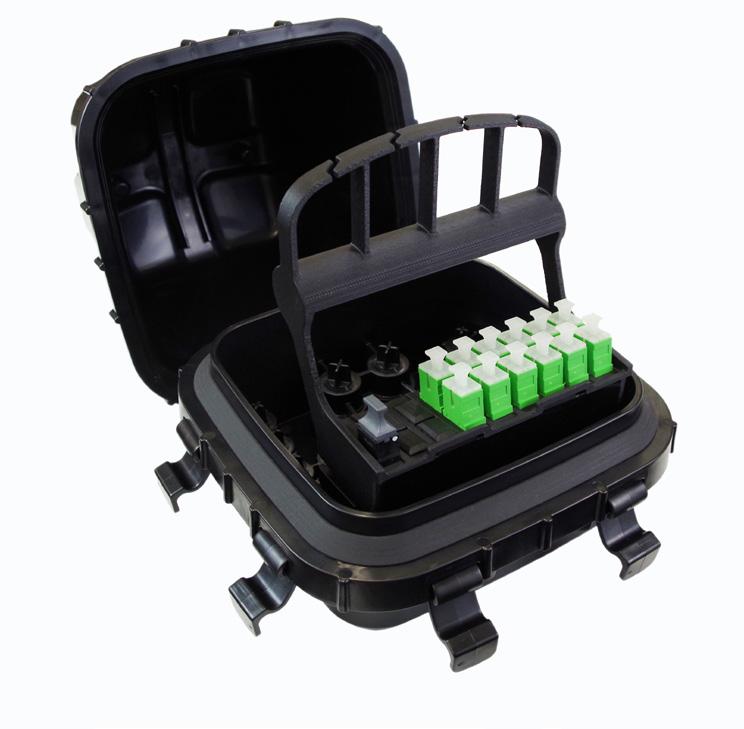
Ducts are simply brought to the YOURx-Terminal, trimmed to length and pushed into the YOURx FlexPorts on the base of the terminalcompleting the protected pathway. Fiber is now pulled or pushed from the customer premise to the “inside” of the YOURx-Terminal, where the connector assembly is completed and mated.
Features
and Benefits
Integrity
• Designed, tested and certified to GR-771
• Terminations designed, tested and certified to GR-326 and GR-1435
• Supports FieldShield Pushable/Pullable SC Connectors for drop applications
• Supports pre-terminated FieldShield FLATdrop, FieldShield FLEXdrop, FieldShield StrongFiber or FieldShield Pushable Fiber assemblies for individual drop applications
• 100% performance tested for insertion loss, return loss and final mechanical inspection
Protection
• Optimized for use with FieldShield Microduct and Pushable Fiber solutions
• Designed using black UV resistant thermoplastic material
• Environmentally sealed terminal providing maximum reliability and durability in the harshest OSP environments
• FieldShield FlexConnector provides bend-limiting, strain-relief protection and water-tight seal for FieldShield Cables
Access
• Accepts up to sixteen 10 mm distribution ports (for 10 mm FieldShield Microduct or FieldShield FLATdrop)
• Accepts up to two 14 mm feeder ports (for 14 mm FieldShield Microduct)
• Accepts up to two 10 mm feeder ports (for 10 mm FieldShield Microduct or FieldShield FLATdrop)
• Compact sealed design allows placement above or below grade
• Plug-and-play configurations accept both FieldShield FLATdrop and FieldShield Cable Assemblies
• Optical component solutions maximize existing architectures and relief for fiber exhaust scenarios
Investment
• Modular cartridge for upgrade or repair
• Flexibility in configuration provides maximum scalability across multiple services classes and network applications
• Compatible with all of FieldShield drop cable options, which reduces installation time and labor costs by removing expensive splicing labor from the YOURx-Terminal to customer premise
• Pre-terminated factory polished drop cables improve network operability across multiple network access points
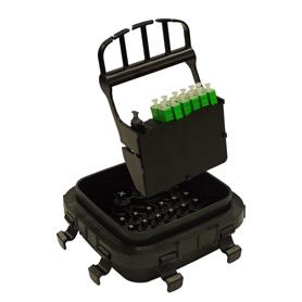

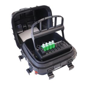
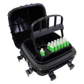
YOURx-Terminal
Technical Specifications
YOURx-Terminal
Dimensions
Material Black UV resistant Thermoplastic
Mounting Options
(Brackets ordered separately. See accessories for options)
Below Grade: vault ( part number: FPB1220)
Above Grade: pedestal, pole mount or aerial/strand
External Slack Storage Virtually unlimited - depends on vault size or mounting application
Feeder Ports Two 14 mm FlexPorts and two 10 mm FlexPorts
Distribution Ports 16, 10 mm FlexPorts
Connector Types SC/APC, SC/UPC, LC/APC, LC/UPC
YOURx-Terminal - MPO
Application: MPO Feeder with Drops
Example Above: 12 fiber MPO feeder with 4 SC/APC drops.
Terminal Part Number: FSTX-04C-51Z-ZAZ
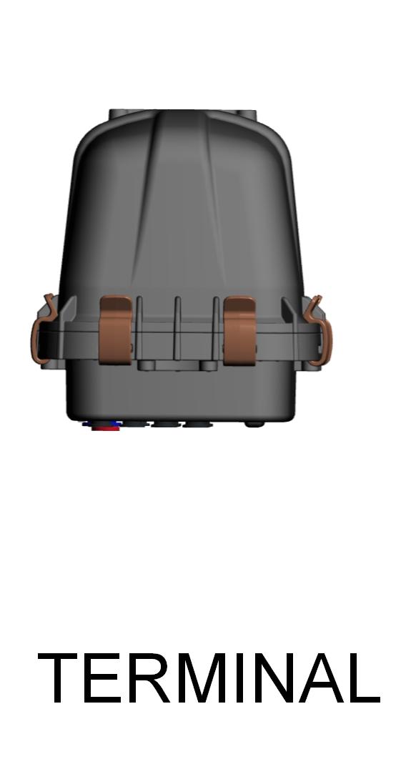

YOURx-Terminal - MPO Configured Part Number 1 2 3
1 Select Distribution Port Count
02 = 2 ports (SC/APC Only)
04 = 4 ports
08 = 8 ports
12 = 12 ports
16 = 16 ports (Requires 24F MPO)
2 Select Distribution Connector
3 Select Feeder Connector
5 = 12F MPO (Male) Q = 24F MPO (Male)
For individual drops using FLATdrop with the FlexConnector, you’ll need to order them separately and make reference to that product.
Mounting Brackets sold separately. See Accessory section.
YOURx-Terminal
YOURx-Terminal - Patch Only
Application: Pre-terminated Patch Only and Drops

Example Above: Factory installed 150’ 12 fiber flat drop toneable feeder with 4 SC/APC drops.
Terminal Part Number: FSTX-04C-Z1U-ZZZ 0150F
YOURx-Terminal - Patch Only Configured Terminal
1 Select Distribution Port Count
04 = 4 ports
06 = 6 ports
08 = 8 ports
12 = 12 ports
2 Select Distribution Connector
A = SC/UPC
C = SC/APC
F = LC/UPC
H = LC/APC
Select Feeder Mode and Type
= SM (Non-ribbon)
Select Feeder Jacket Construction T = FLATdrop (Non -toneable)
= FLATdrop (Toneable)
= FieldShield
Select Feeder Cable Length
= Length in Feet
= Length in Meters
For individual drops using FLATdrop with the FlexConnector, you’ll need to order them separately and make reference to that product.
YOURx-Terminal — Expressed/Daisy Chain
Application: MPO Feeder with Drops and MPO Expressed Out


Example above: 12 fiber MPO feeder with 4 SC/APC drops and remaining fibers expressed out
Terminals Part Numbers: FSTX-12X-51Z-ZZZ-03
Internal Configuration:
* 12 Fiber MPO-MPO Assemblies between Terminals simplifies installation.
Advantage: Same terminal, only one part number to maintain, simplifying the installation.
YOURx-Terminal - Expressed Configured Terminal With 12F MPO Input
1 Select Input MPO Connector
Select Number
Select Number of Fibers Expressed Out (Shifted)
5 Select MPO Connector Type Expressed Out (Same MPO Connector as Listed in #1)
= 12F MPO (Male)
= 24F MPO (Male)
YOURx-Terminal - Splitter
Application: Single Fiber Feeder with Drops

Example Above: Single fiber feeder with SC/APC 1x4 splitter and 4 SC/APC drops.
Terminal Part Number: FSTX-04C-CZZ-8ZZ
1 Select Distribution Port Count
02 = 2 ports
04 = 4 ports
08 = 8 ports
12 = 12 ports
16 = 16 ports
2
Select Distribution Connector A
Internal Cabling in YOURx-Terminal.
Drop Assemblies

Connector in Terminal Connector to House FieldShield (requires microduct)
Flat Drop Toneable (does not require microduct)
Flat Drop Non-toneable (does not require microduct) SCA SCA
FS-AA1-001-CQZ-DZZ XXXXF
FSH-U1-001-D1K-CQK XXXXF FSH-T1-001-D1K-CQK XXXXF
FS-AA1-001-AQZ-BZZ XXXXF FSH-U1-001-B1K-AQK XXXXF FSH-T1-001-B1K-AQK XXXXF
Drop Options Using YOURx-TAP with Deploy Reel

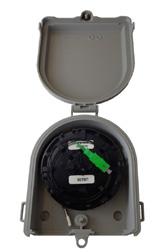
YOURx-TAP, loaded with 1 fiber SC/APC to pullable SC/APC, 300’ blank and dual plate, no logo
* Additional TAP options are available. See Clearfield website under Test Access Products.
MPO - MPO Feeder Cable Assemblies Between Terminals
* FLATdrop Toneable and Non-Toneable 12 Fiber MPO-MPO are available. Contact Clearfield for more information. Requires microduct

FS-AA1-012-PZZ-PZZ XXXXF FieldShield Pushable Fiber, Singlemode, 12 Fiber, 1 x 12 Pushable MPO Female to Pushable MPO Female
Terminal Mounting Options
Application: Pole, Wall, Pedestal (Min. 10” Pedestal, Vault)

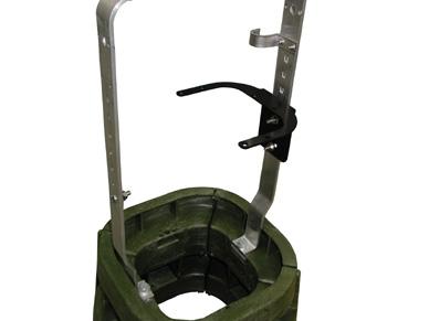
Application: Aerial Strand Mount

Application: Required for sealing in terminal when field-installing connectors or using pushable FieldShield Connector. Part
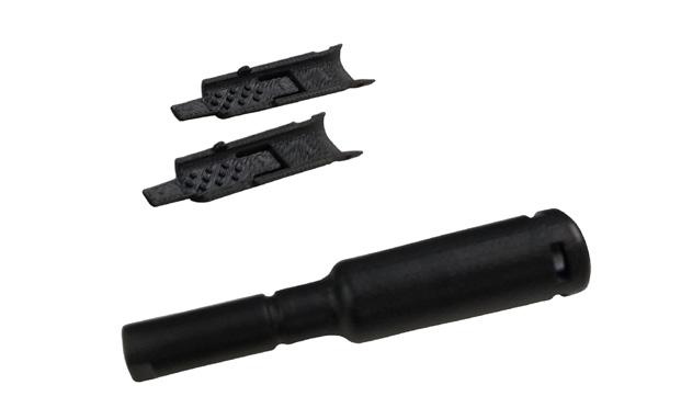
FS-FIFC-103-6PAK Field installable FlexConnector, 10 mm Port, 3 mm Cable, Black Grommet, 6 Pack (FLEXdrop and FieldShield)
FS-FIFC-143-6PAK Field installable FlexConnector, 14 mm Port, 3 mm Cable, Gray Grommet, 6 Pack, Required for Pushable MPO
FS-FIFC-144-6PAK Field installable FlexConnector, 14 mm Port, 4 mm Cable, Red Grommet, 6 Pack, Required for 24 fiber applications
Accessories
Top Mount Bracket Kit for YOURx-Terminal
Description
Bracket mounts to cover, allowing the YOURx-Terminal to be removed by loosening a wing nut. Includes the top bracket, plate, wing nut and screws. Applications: Pole mount, wall mount, pedestal mount (minimum 10” (254.00 mm) pedestal) or vault mount. Pre-Configured Part Numbers
Bottom Mount Bracket Kit for YOURx-Terminal
Description
Terminal is bolted to bracket from the bottom. Terminal is accessed by removing the cover. Includes the bracket and screws. Applications: Pole mount, wall mount, pedestal mount (minimum 10” (254.00 mm) pedestal) or vault mount.
Pre-Configured
Part Numbers
Aerial/Strand Mounting Kit for YOURx-Terminal
Description
Bracket mounts to strand with two clamps. Terminal is accessed by removing the cover. Includes the top bracket, bottom bracket with wire cable support, lanyard and screws. Applications: Aerial/strand mount. Pre-Configured Part Numbers
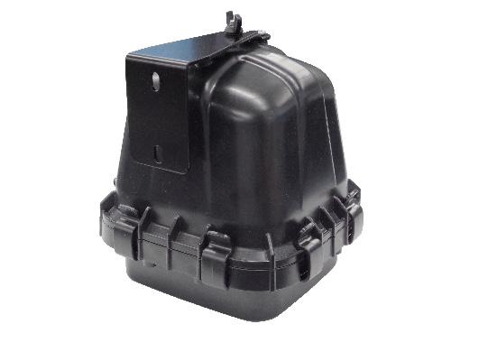
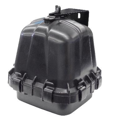

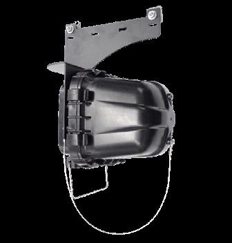
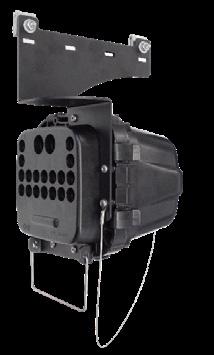
Description
Individual YOURx FlexPort for securing 10 mm or 14 mm microduct into the YOURxTerminal or YOURx-TAP. Includes the outer coupler, inner housing and O-ring.
Pre-Configured Part Numbers

YOURx ®
YOURx-Terminal Accessories
Slack Storage Reel for YOURx-Terminal
Description
Reel is stored on the inside of the YOURx-Terminal, between the base and the FlexCartridge™. The reel will hold up to 10 feet (254.00 mm) of FieldShield ® fiber slack.
Pre-Configured Part Numbers
Part
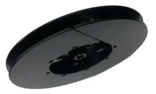
FSTX-SLACK-REEL Real, slack storage for YOURx-Terminal, holds 10 feed of FieldShield
YOURx FlexPort Filler Plug
Description
YOURx FlexPort Filler Plug for 10 mm or 14 mm ports into the YOURx-Terminal or YOURxTAP. Application: Used for sealing YOURx FlexPort holes if plug on the inside is removed.

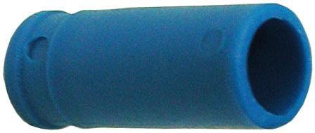
Pre-Configured Part Numbers
YOURx Expansion Repair Kit
Description
Used to expand or add-drop feeder ports for YOURx-Terminal or YOURx-TAP.
Pre-Configured Part Numbers
Part
FSX-EXPANSION REPAIR KIT Expansion, Repair Kit for YOURx-Terminal and YOURx-TAP, Includes four 10 mm YOURx FlexPorts, four 10 mm YOURx FlexPort Plugs, one 14 mm YOURx FlexPort and one 14 mm YOURx FlexPort Plug
YOURx Pulling Tool
Pre-Configured Part Numbers
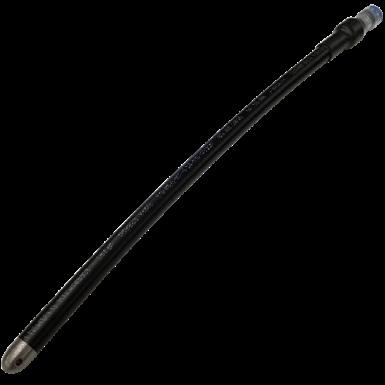
FieldShield Field Installable FlexConnector
Description
For field installed applications, these three kits allow a water-tight transition from 3mm and 4mm cable, into the FieldShield FlexPort. The kits include enough parts for six tool-less installations.
Pre-Configured Part Numbers
Part

Description
FS-FIFC-103-6PAK Field installable FlexConnector, 10 mm Port, 3 mm Cable, Black Grommet, 6 Pack
FS-FIFC-143-6PAK Field installable FlexConnector, 14 mm Port, 3 mm Cable, Gray Grommet, 6 Pack
FS-FIFC-144-6PAK Field installable FlexConnector, 14 mm Port, 4 mm Cable, Red Grommet, 6 Pack
YOURx Removal Tool
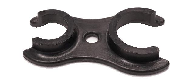
Pre-Configured Part Numbers
YOURx Breakout from FlexPort in 10 pack
YOURx ®
YOURx-Aerial Terminal - Patch and Splice
Application
When the network deployment plan calls out for an aerial application, Clearfield’s YOURxAerial Terminal application allows for the flexibility to terminate a feeder fiber, directly into revenue generating drops and has the capability to accommodate a fiber cable mid-span, allowing cables to be fully utilized while feeding multiple terminals and access points.
Description
Designed with many of the same features as the YOURx-Terminal, the YOURx-Aerial Terminal allows for aerial or strand mount fiber deployment within the network architecture. The YOURx-Aerial Terminal can accept the “hand-off” of fiber and distribute up to 24 individual service drops and has the capability to mid-span a larger count fiber cable, allowing the service provider to deploy multiple terminal/access points along the same cable run, maximizing the investment in fiber deployment.
Designed for easy, craft accessibility, the YOURx-Aerial Terminal application has an upward hinging, kickstand supported cover with four side entrance cable access ports. Two individual compartments separate the incoming splices from the drop ports for network security. The backplane of the unit has the capacity to hold up to three splice trays, incorporating fiber management and bend-radius protection into the design. Each splice tray supports 24 loose tube or 72 ribbon splices. With up to 24 individual drops terminated to SC of LC connectors, the YOURx-Aerial Terminal can accept all of the FieldShield ® drop options, as well as other cable drop options.
Features and Benefits Integrity
• Desgined to comply to Telcordia GR-771
• Terminations designed, tested and certified to Telcordia GR-326
• Supports FieldShield Pushable Duct and pushable/pullable fiber solution with SC connectors for drop applications
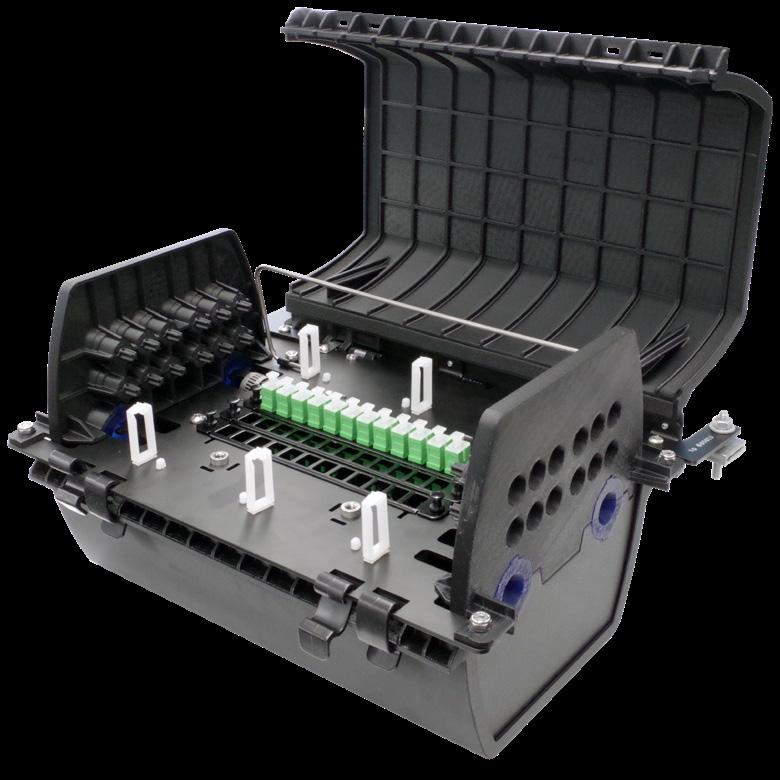
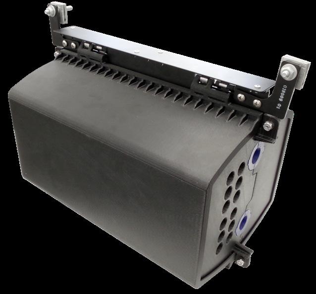
• Supports pre-terminated FieldShield FLATdrop cable assemblies for individual drop applications
• 100% performance tested for insertion loss, return loss and final mechanical inspection Protection
• Optimized for use with FieldShield Microduct and Pushable Fiber, as well as FieldShield FLATdrop cable assemblies
• Black UV resistant thermoplastic designed to resist corrosion
• Free breathing terminal provides durability and protection in the OSP environments
• 10 mm YOURx FlexPort provide duct/fiber protection as well as strain relief for drop cables Access
• Four side entrance holes accept multiple cable types - up to 144 fiber count - not to exceed ¾” (19.05 mm) O.D.
• Mid-span capabilities
• Two secure compartments, separate splices from the drop ports, providing network security
• Up to 24 drops
• Up to 72 ribbon splices or 24 loose tube splices per tray (maximum of three trays)
• Hinged cover allows easy access for installation and network maintenance
• Patch and splice (Clearfield’s in-terminal splicing solution)
• Optical component solutions maximize existing architectures and eliminate fiber exhaust scenarios
• Designation card included Investment
• Customer defined configurations - provides maximum scalability across multiple services classes
• “Grow-as-you-go” capabilities
• Pre-terminated factory polished pigtail assembly - insures improved network operability when spliced onto the feeder cable
YOURx ®
YOURx-Aerial Terminal - Patch and Splice
Technical Specifications
YOURx-Aerial Terminal - Patch and Splice
Dimensions 14.80” W x 11.61” H x 8.15” D (375.92 mm x 294.89 mm x 207.01 mm) (height includes strand bracket)
Material Black UV resistant Thermoplastic
Mounting Options Aerial or Strand Mount
Internal Slack Storage Up to 8 feet of ribbon; up to 8 feet of loose tube
Feeder Ports Four silicone sealed ports on ends of unit; two on each end
Distribution Ports Up to 24 - 10 mm YOURx FlexPorts that accept FieldShield® Microduct or FLATdrop connectors
Connector Types SC/APC, SC/UPC, LC/APC, LC/UPC
Splicing Capabilities 24 loose tube or 72 ribbon splices per tray; three splice trays per terminal
Configured Part Numbers

1 Select Distribution Port Count (FlexPorts will match distribution ports)
06 = 6 ports
12 = 12 ports
24 = 24 ports

2 Select Distribution Connector
= SC/UPC
= SC/APC
= LC/UPC
= LC/APC

Select Fiber Type
1 = Loose Tube (6, 12 or 24 port)
2 = Ribbon (12 and 24 port)
Select Number of Splice Trays
1 = 1 tray (standard)
2 = 2 trays
3 = 3 trays
YOURx ®
Terminal - Patch and Splice
Pre-Configured Part Numbers
AFT-HANGER-01
Adjustable aerial hanger bracket for YOURx-Aerial Terminal; allows terminal to be installed over existing utilities; shipped in pairs. Includes brackets for mounting to terminal.
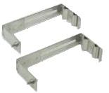
019501
Ribbon retention grommet and clip to secure ribbon into splice tray of YOURx-Aerial Terminal. Includes 6 pieces of each.
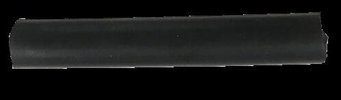

019527
Grounding kit for YOURx-Aerial Terminal, kit includes ground wire and two clamps

019007
Silicon grommet for incoming cables on YOURx-Aerial Terminal, one grommet (two pieces)
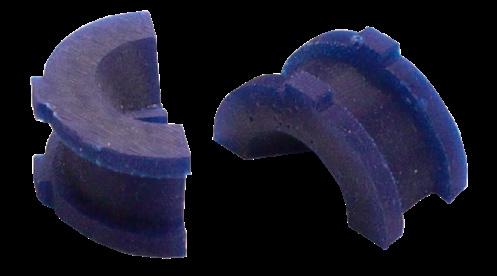
016280-06
YOURx FlexPort, push to connect, 10 mm, 6 pack
016280-12 YOURx FlexPort, push to connect, 10 mm, 12 pack 018664 YOURx FlexPort Plug, filler for 10 mm
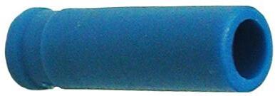
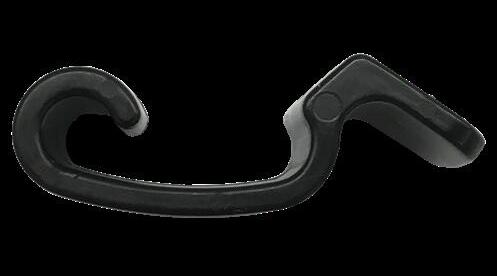
- Patch and Splice
FSH-FIFC-4PAK Field installable FlexConnector™ with pieces for 4 terminations
FSH-FIFC-SCA-4PAK Field installable FlexConnector with splice-on SCA connectors and pieces for 4 terminations
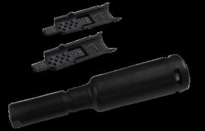
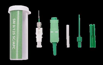
Introduction to FieldShield ®
FieldShield Fiber, Drops and Microduct
Installing fiber where you want it, when you want it and cost-effectively is the promise of the FieldShield Optical Fiber Protection System. FieldShield is a turn-key system to take fiber through the fields and streets to the home or business, up the tower to the antenna or throughout the riser to the data center or desk. Used in conjunction with Clearfield ® FieldSmart ® fiber management solutions for the CO, Outside Plant and access network, FieldShield delivers and protects fiber through every distribution point of the network.
Components of the FieldShield System include:
• FieldShield Microduct
• FieldShield Pushable Optical Fiber and Connectors
• FieldShield Drop Cables
• FieldShield Assist Module and Accessories
FieldShield
Microduct
FieldShield starts with a ruggedized microduct in a 10 mm or 14 mm outer diameter space-saving footprint across all deployment environments to support your aerial, direct-bury and inside plant last mile needs. FieldShield Microducts can be placed using traditional placement methods allowing you to leverage your existing conduit placement equipment of boring or plowing methods. FieldShield Microducts can also be placed using newer, less disruptive technologies such as saw cutting or micro-trenching. Due to the column strength of the FieldShield Microduct, occupied duct that was thought to be exhausted, can almost always accommodate FieldShield duct as the product can be deployed as a rod directly within the larger duct. Optional pulling carrots make installation of microduct inside a larger occupied duct a simple operation.
Available for aerial and buried environments in the outside plant as well as in a plenum configuration or riser environment, FieldShield Microduct provides the pathway to quickly deliver a crush-resistant FieldShield pushable fiber assembly.
FieldShield Pushable Optical Fiber and Connectors
Manufactured with bend-insensitive fiber, FieldShield Pushable Optical Fiber is strong enough to be stapled to walls and offers a built-in, bendlimiting function to prevent damage to fiber during installation. Available in bulk reels, FieldShield offers total installation flexibility. Terminated with a FieldShield Pushable Fiber Connector, the polymer properties unique to FieldShield Pushable Optical Fiber allow the assembly to be pushed or pulled through the FieldShield Microduct.
Terminating a FieldShield Pushable Fiber Connector onto FieldShield Fiber Cable allows it to be pulled or pushed through the FieldShield Microduct. Various connector styles are available including singlemode simplex SC/APC or SC/UPC, simplex or duplex LC/APC or LC/UPC and singlemode MPO. FieldShield Fiber Connectors are factory polished to achieve consistent high performance optical parameters. With a small profile, they can easily be pushed through FieldShield Microduct. The inner and outer housings are easily snapped in place by the technician in the field after the connector is pulled through the microduct. This factory pre-connectorized approach lowers installation costs by reducing costly labor in the field. Additionally, it presents a more reliable and consistent performance level compared to field installed connectors or field splices. Whether you choose to push or pull the fiber into the FieldShield Microduct, the PBT jacketing of the Clearfield FieldShield Pushable Fiber easily slips through the microducts smooth inner wall.
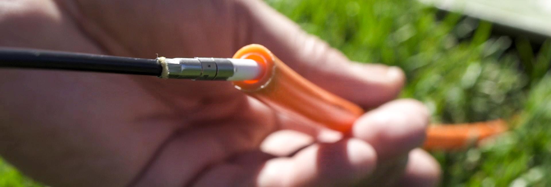
Introduction to FieldShield ® FieldShield Fiber, Drops and Microduct
FieldShield Drop Cables
• FieldShield FLATdrop – lowest initial capital expenditure
• FieldShield D-ROP – flat drop functionality plus one-pass installation and easy restorability
Recognizing that no two networks are alike, Clearfield has developed the industry’s widest choice of drop cable solutions – giving you the flexibility of configuration that best suits your network environment, network design and drop cable needs.
• FieldShield FLEXdrop – increased flexibility for turns and bends. UL Listed for Plenum applications and UV stabilized for outdoor use as building wrap
• FieldShield Pushable Optical Fiber – increased rigidity for pushing/pulling extended distances through a ducted pathway
• FieldShield StrongFiber –innovative, spool-based technology offers craft-friendly deployment and simplified, small footprint slack storage
Utilizing factory terminated connectors, all FieldShield Drop Cables provide plug-and-play connectivity. When the assembly is equipped with a FieldShield FlexConnector, gone are the days of proprietary connections. The FlexConnector allows multiple size and type of last mile drop cables to interconnect the YOURx-Terminal and the YOURx-TAP.
FieldShield Assist Module and Other Accessories
Clearfield offers a number of FieldShield Microduct and Fiber Cable accessories to help install and complete a project. The FieldShield Assist Module can be used to enhance the pull/push experience by providing a continuous force on the FieldShield Fiber Cable being pushed into the FieldShield Microduct. Compared to hand push installation, the Assist Module can extend installations to 500 feet (152.40 meters) or more. The Assist Module also has an integrated clutch mechanism that releases the installation force should there be an unexpected resistance caused by too many corners passed or an excessively sharp bend of the microduct. Other accessories range from couplers and end caps to pulling eyes/carrots and socks for FieldShield Microduct and Fiber Cable.


FieldShield ® Pushable Optical Fiber
Application
Designed to simplify the placement of fiber, FieldShield Pushable Optical Fiber reduces the cost of any fiber deployment, while providing industry leading protection when mated with FieldShield Microducts. Pushable Optical Fiber is either pulled or pushed through microduct at turn-up, maximizing installation efficiency. In the event of a later fiber cut, the fiber can be easily pulled from the microduct. The duct is then repaired and a new FieldShield Pushable Assembly is pushed or pulled through the microduct for a fast and cost-effective restoration.
Description
FieldShield Pushable Optical Fiber is a durable and crush resistant product that is suitable for most indoor or outdoor environments. Manufactured using PBT jacketing, pushable optical fiber offers flexibility as well as resistance to chemicals. FieldShield Pushable Optical Fiber is typically recommended to be used in conjunction with FieldShield Microduct.
Features and Benefits Integrity
• FieldShield fiber cable designed, tested and certified to Telcordia GR-20
• Available in singlemode
• Supports all industry standard connectors Protection
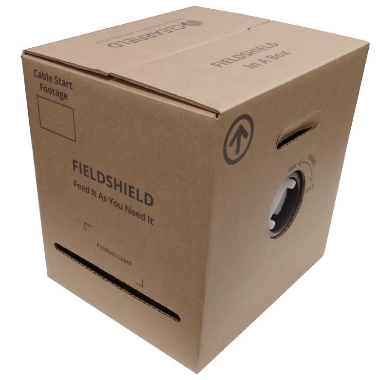
Available in 1, 2, 6, 12, 24 and 48 fiber counts
• Bend-insensitive (G.657.A2) fiber protects optical signal with minimal to zero attenuation down to a 10 mm radius
• Tough PBT jacketing provides high column strength and low coefficient of friction to maximize push and pull distances
• Lightweight and high crush resistance
• One and two fiber drops protected by water blocking Kevlar strength member
• 6 to 48-fiber utilize water blocking gel Access
• Standard color is black
• Tech-friendly 250 μm fiber inside the outer jacket reduces splicing steps and installation costs
• Suitable for all types of indoor and outdoor implementations within a microduct Investment
• Pushes directly into a Clearview ® Cassette, FieldShield is optimized for placement alongside Clearfield ® FieldSmart ® fiber management platforms
• Quick and easy deployment allows capital investment to be aligned to customer take rates
• Available in multiple fiber counts up to 48 fibers
Recommended Push/Pull

FieldShield ®
Pushable Optical Fiber
Technical Specifications
FieldShield Pushable Optical Fiber
Fiber
Water Peak
Bend-Insensitive
Corning ClearCurve Optical Fiber or equivalent
ZWP (Zero Water Peak)
Bend-Insensitive Fiber G.657.A2
Color Code TIA/EIA 598 (US Standard)
Fiber Count
Any fiber count up to 48 fibers
Pushable Connectors FieldShield SC/UPC, SC/APC, Simplex and Duplex LC/UPC, Simplex and Duplex LC/APC, MPO
Standard Connectors SC/UPC, SC/APC, LC/UPC, LC/APC, HFOC SC/APC, MPO
Internal Fiber Size 250 μm
Outside Diameter 1 to 12-fiber : 0.118" (3.0 mm); 24-fiber: 0.156” (3.96 mm); 48-fiber :0.217” (5.51 mm)
Color Black Material
Installation Tension 20 lbf for 3 mm; 20 lbf for 4 mm
Markings Part number, lot number and footage
Pre-Configured Part Numbers
05000F FieldShield
FS-CA1-002-8ZD-B 01000F FieldShield boxed Pushable Optical
FS-CA1-002-8ZD-B 02000F FieldShield boxed Pushable Optical Fiber,
FS-CA1-002-8ZD-B 03000F FieldShield boxed Pushable Optical Fiber, 2-fiber (250 μm), singlemode, 3 mm jacket, 3000 feet (914 m)
FS-CA1-006-8ZD-B 01000F FieldShield boxed Pushable Optical Fiber, 6-fiber (250 μm), singlemode, 3 mm jacket, 1000 feet (305 m)
FS-CA1-006-8ZD-B 03000F FieldShield boxed Pushable Optical Fiber, 6-fiber (250 μm), singlemode, 3 mm jacket, 3000 feet (914 m)
FS-CA1-012-8ZD-B 01000F FieldShield boxed Pushable Optical Fiber, 12-fiber (250 μm), singlemode, 3 mm jacket, 1000 feet (305 m)
FS-CA1-012-8ZD-B 03000F FieldShield boxed Pushable Optical Fiber, 12-fiber (250 μm), singlemode, 3 mm jacket, 3000 feet (914 m)
FS-CA1-024-8ZE-B 01000F FieldShield boxed Pushable Optical Fiber, 24-fiber (250 μm), singlemode, 4 mm jacket, 1000 feet (305 m)
FS-CA1-024-8ZE-B 02000F FieldShield boxed Pushable Optical Fiber, 24-fiber (250 μm), singlemode, 4 mm jacket, 2000 feet (610 m)
FS-CA1-024-8ZE-B 05000F FieldShield boxed Pushable Optical Fiber, 24-fiber (250 μm), singlemode, 4 mm jacket, 5000 feet (1,524 m)
FS-CA1-048-8ZF-B 01500F FieldShield boxed Pushable Optical Fiber, 48-fiber (250 μm), singlemode, 5.5 mm jacket, 1500 feet (457 m)
FS-CA1-048-8ZF-B 02500F FieldShield boxed Pushable Optical Fiber, 48-fiber (250 μm), singlemode, 5.5 mm jacket, 2500 feet (762 m)
FieldShield ® SC and LC Pushable Assemblies
Application
Designed to simplify the deployment of fiber where one or two fibers are required, FieldShield SC and LC Pushable Assemblies provide a tech-friendly field assembled connector that snaps together in seconds without jeopardizing fiber protection or optical reliability. FieldShield Pushable Assemblies greatly reduce installation costs for Fiber to the Home (FTTH) installations, business class services, cell backhaul or any other small count delivery application.
Description
FieldShield Pushable Assemblies are factory terminated and polished SC and LC connectors designed to be terminated on simplex and duplex FieldShield Pushable Optical Fiber Assemblies. After being pushed or pulled through FieldShield Microduct, the smooth wall protective sleeve is easily removed and an outer housing is snapped into place. This creates an industry standard connector without mechanical or fusion splicing. All SC and LC FieldShield Pushable Assemblies styles can be pushed/pulled in all FieldShield Microducts.
Features and Benefits
Integrity
• FieldShield fiber cable designed, tested and certified to GR-20
• Terminations are designed, tested and certified to Telcordia GR-326 and GR-1435

• Available in singlemode SC/UPC, SC/APC, Simplex and Duplex LC/UPC, Simplex and Duplex LC/APC Protection
• Smooth wall protective sleeve is easily removed and an outer housing is snapped into place
• Option for FlexConnector in YOURx applications
Access
• Zirconia ceramic ferrule measuring 1.25 mm O.D.
• Tool-less installation
Investment
• Tech-friendly pre-terminated pushable connectors rapidly decrease deployment times and reduce installation costs by eliminating in-field splicing
• Pushed directly into a Clearview ® Cassette, FieldShield is optimized for placement alongside Clearfield’s FieldSmart ® fiber management platforms
Packaging
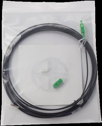
Lengths up to 32’ (9.75 m)

Lengths from 32’ to 350’ (9.75 m to 106.68 m)

Lengths greater than 350’ (106.68 m)
FieldShield ® SC and LC Pushable Assemblies
Technical Specifications
Minimum Performance Specifications for Terminated Singlemode Connectors
Pre-Configured Part Numbers
FS-AA1-001-AZZ-BZZ XXXXF
FS-AA1-001-CZZ-DZZ XXXXF
FS-AA1-002-1ZZ-3ZZ XXXXF
FieldShield pushable patch cord, singlemode, 1-fiber (250 μm), 3 mm jacket standard SC/UPC to pushable SC/UPC, XXXX feet
FieldShield pushable patch cord, singlemode, 1-fiber (250 μm), 3 mm
to pushable SC/APC, XXXX feet
FieldShield pushable patch cord, singlemode, 2-fiber (250 μm), 3 mm jacket duplex LC/UPC to pushable duplex LC/UPC, XXXX feet
FS-AA1-002-2ZZ-4ZZ XXXXF LC FieldShield pushable patch cord, singlemode, 2-fiber (250 μm), 3 mm jacket duplex LC/APC to pushable duplex LC/APC, XXXX feet
Configured Part Numbers
Disclaimer/Note: Paper configurator shown is for reference only and should not be used to configure a saleable product configuration. All options shown on paper configurators may not be available or compatible with other options listed. Please contact your Clearfield representative for assistance in product configurations.
Mode/Type
1 = Singlemode (250 µm) 2 = Singlemode (900 µm)
001 = Simplex
002 = Duplex
Select Connector #1
1 = Pushable LC/UPC 2 = Pushable LC/APC 3 = Dual LC/UPC unibody
= Dual LC/APC unibody
5 = MPO (male)
6 = MPO (female)
B = Pushable SC/UPC
D = Pushable SC/APC
A = SC/UPC
C = SC/APC
E = LC/UPC
G = LC/APC
N = Pushable MPO male
P = Pushable MPO female
W = HFOC SC/APC
Select Breakout #1 B = 1 meter
= Half meter
= YOURx
= N/A
Select Upjacketing #1
A = 900 µm
B = 2 mm (OSP) Z = N/A
Select Connector #2
1 = Pushable LC/UPC
2 = Pushable LC/APC
3 = Dual LC/UPC unibody
4 = Dual LC/APC unibody
5 = MPO (Male)
6 = MPO (Female)
B = Pushable SC/UPC
D = Pushable SC/APC
A = SC/UPC
C = SC/APC
E = LC/UPC
G = LC/APC
N = Pushable MPO male
P = Pushable MPO female
W = HFOC SC/APC
Z = None
Select Breakout #2
B = 1 meter
C = Half meter
P = Pulling eye
Q = YOURx
Z = N/A
Select Upjacketing #2
A = 900 µm
B = 2 mm (OSP)
Z = N/A
= Length in feet
FieldShield ®
SC and LC Pushable Assemblies
Accessories
Field Installable FlexConnector (FIFC)
• Once the cable has been prepped with the FlexConnector, the 3 mm cable is sandwiched between the two retainer clips. The FlexConnector is then pushed and snapped together with the retainer clips, pinching the grommet seal for a water-tight assembly.
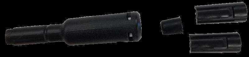
Field Installable FlexConnector Pre-Configured Part Numbers
FS-FIFC-103-6PAK Field installable FlexConnector, 10 mm Port, 3 mm Cable, Black Grommet, 6 Pack
FS-FIFC-143-6PAK Field installable FlexConnector, 14 mm Port, 3 mm Cable, Gray Grommet, 6 Pack
FS-FIFC-144-6PAK Field installable FlexConnector, 14 mm Port, 4 mm Cable, Red Grommet, 6 Pack
Description
For field installed applications, these three kits allow a water-tight transition from 3 mm and 4 mm cable, into the FlexPort. The kits include enough parts for six tool-less installations.
FieldShield ®
MPO Pushable Assemblies
Application
Designed to simplify the deployment of fiber where multiple fibers are required, FieldShield MPO Pushable Assemblies provide a tech-friendly, field-assembled connector that snaps together in seconds without jeopardizing fiber protection or optical reliability. FieldShield Pushable Assemblies greatly reduce installation costs for Fiber to the Home installations, business class services, cell backhaul or any other small count delivery application.
Description
FieldShield Pushable Assemblies are factory terminated and polished. MPO Assemblies are designed to be terminated on 6, 12 or 24-fiber FieldShield Pushable Optical Fiber Assemblies. After being pushed or pulled through FieldShield Microduct, the black protective sleeve is easily removed and the green MPO outer housing is snapped into place creating an industry standard connector without mechanical or fusion splicing. FieldShield Pushable MPO Assemblies can be pulled/pushed in 14/10 mm FieldShield Microduct.
Features and Benefits
Integrity
• Singlemode terminations are designed, tested and certified to Telcordia GR-326
• Available in singlemode 4, 6, 8, 12 and 24-fiber terminations
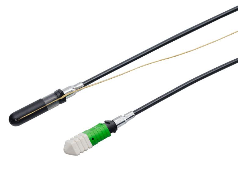

• FieldShield MPO Pushable Assemblies use high-quality components that keep the connector insertion loss to a maximum of 0.35 dB (1.00 dB 24 fiber)
Protection
• Smooth wall protective sleeve is easily removed and an outer housing is snapped into place
Access
• Thermoplastic high-precision ferrules
• Tool-less installation
Investment
• Tech-friendly, pre-terminated pushable assemblies decrease deployment times and reduce installation costs by eliminating in-field splicing
• Pushed directly up to a Clearview ® Cassette, FieldShield is optimized for placement alongside FieldSmart ® fiber management platforms
Technical Specifications
FieldShield MPO Pushable Assemblies
Connector Type MPO
Ferrule Material Thermoplastic Polish Type APC
Insertion Loss Typical 0.25 dB (12 fiber) 0.75 dB (24 fiber)
Maximum Insertion Loss 0.35 dB (12 fiber) 1.00 dB (24 fiber)
Minimum Return Loss 55.00 dB (12 and 24 fiber)
MPO Pushable Fiber in duct
FieldShield ® MPO Pushable Assemblies
Pre-Configured Part Numbers
Part Number Description
FS-AA1-006-PZZ-ZZZ XXXXF
FS-AA1-008-PZZ-6ZZ XXXXF
FS-AA1-012-PQZ-ZZZ XXXXF
FS-AA1-012-PQZ-PZZ XXXXF
FS-AA1-012-PZZ-ZZZ XXXXF
FieldShield pushable pigtail, singlemode, 6-fiber (250 µm) 3 mm jacket 1 x 6 pushable MPO female to pigtail, XXXX feet
FieldShield pushable patch cord, singlemode, 8-fiber (250 µm), 3 mm jacket 1 x 8 pushable MPO female to standard 1 x 8 MPO female, XXXX feet
FieldShield Fiber Pigtail, Singlemode, 12 Fiber, 1 x 12 Pushable MPO Female With YOURx Connector Installed to Pigtail
FieldShield Fiber Patchcord, Singlemode, 12 Fiber, 1 x 12 Pushable MPO Female With YOURx Connector Installed to Pushable MPO Female
FieldShield pushable pigtail, singlemode, 12-fiber (250 µm), 3 mm jacket 1 x 12 pushable MPO female to pigtail, XXXX feet
Configured Part Numbers
Disclaimer/Note: Paper configurator shown is for reference only and should not be used to configure a saleable product configuration. All options shown on paper configurators may not be available or compatible with other options listed. Please contact your Clearfield representative for assistance in product configurations.
Select Breakout #1
B = 1 meter
C = Half meter
Q = YOURx
Connector #1
1 = Pushable LC/UPC
2 = Pushable LC/APC
3 = Dual LC/UPC unibody
4 = Dual LC/APC unibody
5 = MPO (male)
6 = MPO (female)
B = Pushable SC/UPC
D = Pushable SC/APC
A = SC/UPC
C = SC/APC
E = LC/UPC
G = LC/APC
N = Pushable MPO male
P = Pushable MPO female
Q = MPO (24 fiber male)
QS = MPO Swap-12 (24 fiber male)
R = MPO (24 fiber female)
RS = MPO Swap-12 (24 fiber female)
S = Pushable MPO (24 fiber male)
SS = Pushable MPO Swap-12 (24 fiber male)
T = Pushable MPO (24 fiber female)
TS = Pushable MPO Swap-12 (24 fiber female)
W = HFOC SC/APC
Select Upjacketing #1
B = 2 mm (OSP)
D = 3 mm
Z = N/A 6
Z = N/A 5
Select Connector #2
1 = Pushable LC/UPC
2 = Pushable LC/APC
3 = Dual LC/UPC unibody
4 = Dual LC/APC unibody
5 = MPO (Male)
6 = MPO (Female)
B = Pushable SC/UPC
D = Pushable SC/APC
A = SC/UPC
C = SC/APC
E = LC/UPC
G = LC/APC
N = Pushable MPO male
P = Pushable MPO female
Q = MPO (24 fiber male)
R = MPO (24 fiber female)
S = Pushable MPO (24 fiber male)
T = Pushable MPO (24 fiber female)
W = HFOC SC/APC
Z = None
Select Breakout #2
B = 1 meter
C = Half meter
P = Pulling eye
Q = YOURx
Z = N/A
7
Select Upjacketing #2
B = 2 mm (OSP)
D = 3 mm
Z = N/A
XXXM or XXXF
XXXXM = Length in meters
XXXXF = Length in feet
FieldShield ®
Pushable 3 mm Optical Fiber with 900 μm Tight Buffer Fiber
Application
Designed to simplify the placement of fiber, FieldShield Pushable Optical Cable with 900 μm Tight Buffer Fiber reduces the cost of any fiber deployment while providing industry leading protection when mated with FieldShield Microducts. Pushable Fiber is either pushed or pulled through the microduct at turn-up, maximizing installation efficiency. Once deployed, the cable is cut to the specific application length and terminated with a CraftSmart ® Splice-On Connector.
Description
FieldShield Pushable Optical Cable is a durable and crush resistant product that is suitable for most indoor or outdoor environments. Manufactured using PBT jacketing, pushable optical fiber offers flexibility as well as resistance to chemicals. FieldShield Pushable Optical Fiber is typically recommended to be used in conjunction with FieldShield Microduct.
Features and Benefits Integrity
• Available in singlemode
• Supports all industry standard connectors

• Only solution approved for use with FieldShield Pre-terminated Pushable Connectors Protection
• Bend-insensitive (G.657.A2) fiber protects optical signal with minimal to zero attenuation down to a 10 mm radius
• Tough PBT jacketing provides high column strength and low coefficient of friction to maximize push and pull distances
• Lightweight and high crush resistance makes Pushable Optical Fiber strong enough to be stapled directly to walls studs, joists and around corners
Access
• Standard color is black
• Tech-friendly 900 μm fiber inside the outer jacket for applications where CraftSmart ® Splice-On Connectors are used
• Suitable for all types of indoor and outdoor implementations Investment
• Pushes directly into a Clearview ® Cassette, FieldShield is optimized for placement alongside Clearfield ® FieldSmart ® fiber management platforms
• Quick and easy deployment allows capital investment to be aligned to customer take rates
FieldShield ®
Pushable 3 mm Optical Fiber with 900 μm Tight Buffer Fiber
Technical Specifications
FieldShield Pushable 3 mm Optical Fiber with 900 μm Tight Buffer Fiber
Fiber OFS All Wave Flex Fiber or equivalent
Water Peak
Bend-Insensitive
Color Code
ZWP (Zero Water Peak)
Bend-Insensitive Fiber G.657.A2
TIA/EIA 598 (US Standard)
Fiber Count 1 fiber
Pushable Connectors
FieldShield SC/UPC, SC/APC, LC/UPC, LC/APC
Standard Connectors SC/UPC, SC/APC, LC/UPC, LC/APC, HFOC SC/APC
Mode Singlemode
Internal Fiber Size 900 μm Tight Buffer
Color Black
Outside Diameter 0.118" (3 mm)
Material PBT
Bend-Radius 10 mm minimum
Operating Temperature -40°F to 176°F (-40°C to 80°C)
Installation Temperature -14°F to 158°F (-26°C to 70°C)
Markings Part number, lot number and footage markers every two feet (609.60 mm)
Physical Characteristics
FieldShield Pushable 3 mm Optical Fiber with 900 μm Tight Buffer Fiber
Clad Diameter 125.0 ± 0.7 μm
Clad Non-circularity ≤ 1 %
Core/Clad Concentricity Error (Offset) ≤ 0.5 μm maximum, < 0.2 μm typically
Coating Diameter (Uncolored) 900 μm Tight Buffer
Coating-Clad Concentricity Error (Offset) ≤ 12 μm
Tensile Proof Test
kpsi (0.69 GPa) Coating Strip Force Range
Pre-Configured Part Numbers
FS-CC1-001-8ZD-B 01000F FieldShield pushable optical fiber, one fiber (900 μm), singlemode, 3 mm jacket, 1000 feet (304.80 m)
FS-CC1-001-8ZD-B 02000F FieldShield pushable optical fiber, one fiber (900 μm),
StrongFiber FieldShield ®
Application
Designed to simplify the placement of fiber, FieldShield StrongFiber reduces the cost of any fiber deployment while providing industry leading protection when combined with FieldShield Microducts. StrongFiber is pulled through microduct at turn-up maximizing installation efficiency. In the event of a duct or fiber being damaged or for future upgrades, the fiber can be easily pulled from the microduct. The duct is then repaired and a new FieldShield StrongFiber assembly is pushed or pulled through the microduct for a fast and cost-effective restoration or upgrade.
StrongFiber may be used in place of a traditional patch cord for reduced cable pileup within the route-path of new or traditionally oversubscribed frames within a central office, headend, data center or remote hut. StrongFiber is 85% smaller than traditional 3 mm patch cords and 69% smaller than 1.2 mm patch cords. The reduced size and weight makes the fiber less susceptible to micro-bends and makes it much easier to store using any fiber management element.
Description
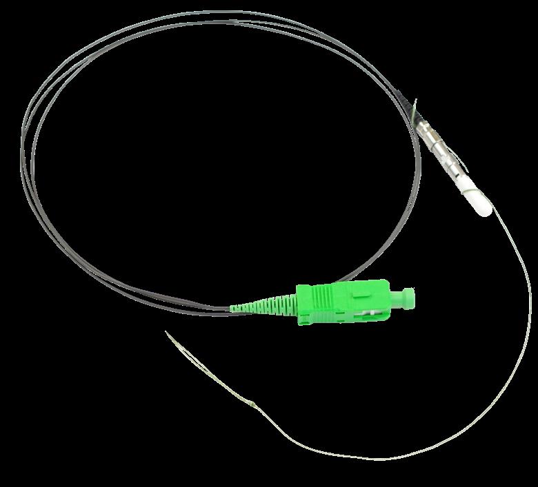
FieldShield StrongFiber is a durable high tensile strength fiber when compared to other fibers of its size. It is suitable for both indoor and outdoor environments when used in FieldShield Microduct. Manufactured with premium bend-insensitive fiber, FieldShield StrongFiber offers high tensile strength to resist damage to the fiber during installation in the FieldShield Microducts. When terminated with a FieldShield Pullable Connector, the FieldShield StrongFiber can be quickly deployed in FieldShield Microduct, reducing installation time drastically.
Features and Benefits
Integrity
• StrongFiber fiber cable designed, tested and certified to Telcordia GR-20
• Available in singlemode
• Supports all SC and LC connectors Protection
• Bend-insensitive (G.657.A2) fiber protects optical signal with minimal to zero attenuation
• Lightweight with low coefficient of friction to maximize pull distances Access
• Standard color is black
• Tech-friendly 900 μm fiber
• Suitable for all types of indoor implementations Investment
• Quick and easy deployment allows capital investment to be aligned to customer take rates
Technical Specifications
FieldShield
®
StrongFiber
FieldShield StrongFiber
Fiber OFS All Wave Flex + Fiber or equivalent
Water Peak ZWP (Zero Water Peak)
Bend-Insensitive Meets G.657 A2
Color Black
Length Up to 300 feet (91.44 m)
Fiber Count Single Fiber
Pullable Connectors FieldShield SC/UPC, SC/APC
Standard Connectors SC/UPC, SC/APC, LC/UPC, LC/APC
Mode Singlemode
Outside Diameter 900 μm
Material
Thermoplastic Blend, Low Smoke/Fume, Non-Halogen Flame Retardant
Rating OSP Temperature Rated
Bend-Radius 10 mm minimum
Operating Temperature -40°F to 176°F (-40°C to 80°C)
Installation Temperature -14°F to 158°F (-26°C to 70°C)
Installation Tension 18 lbs (8.16 kg)
Performance Specifications
Configured Part Numbers
Disclaimer/Note: Paper configurator shown is for reference only and should not be used to configure a saleable product configuration. All options shown on paper configurators may not be available or compatible with other options listed. Please contact your Clearfield representative for assistance in product configurations.

1 Select Connector #1
B = Pullable SC/UPC
D = Pullable SC/APC
A = SC/UPC
C = SC/APC
E = LC/UPC
G = LC/APC

Z = Pigtail 2
2 Select Connector #2
B = Pullable SC/UPC
D = Pullable SC/APC
A = SC/UPC
C = SC/APC
E = LC/UPC
G = LC/APC

StrongFiber Deploy Reel FieldShield ®
Application
Due to the high variability of MDU architectures, extensive engineering has been required to ensure proper cable lengths for Fiber to the Premises deployments. The 4.5” (114.30 mm) FieldShield StrongFiber Deploy Reel minimizes pre-engineering because it allows StrongFiber to be pulled from the reel directly to the access point. Once the pullable connector has reached its destination, the connector assembly is completed with the supplied connector housings and the connector is mated to the adapter. The remaining slack on the reel is pre-stored with no further slack management required. The terminated end on the reel is pre-tested, cleaned and mated in a Clearfield ® factory environment, leaving the technician to simply mate the patch cord to the adapter on the reel. The small form factor of the cable assembly and Deploy Reel allows the StrongFiber to be pulled and slack stored from the customer demarcation point. As an ISP Cable, StrongFiber reduces pre-engineering and on-site installation time for MDU and riser deployments.
Description

The FieldShield StrongFiber Deploy Reel is a 4.5” x 1.5” (114.30 mm x 38.00 mm) spool designed to hold up to 300 feet (91.44 m) of FieldShield StrongFiber. It has a pre-mated adapter that can easily be mounted into a small form factor fiber management element. The small form factor of the 900 μm fiber makes slack storage minimal and easy to accommodate, while the exceptional pull strength of StrongFiber makes it craft-friendly and easy for the technician to handle without fear of fiber damage. Less cable weight means reduced co-efficient of friction (COF). This results in quicker installations because there is minimal friction as the cable is pulled through bends and turns throughout the microduct route-path. Reducing the size requirements of the access point (above or below grade) provides a more aesthetically pleasing solution.
Features and Benefits
Integrity
• StrongFiber is designed, tested and certified to GR-20
• Terminations are designed, tested and certified to GR-326
• StrongFiber Deploy Reel has been designed, tested and certified to GR-63
• Supports singlemode SC connectors
Protection
• Deploying StrongFiber with a FieldShield StrongFiber Deploy Reel allows the installer to payout the exact amount of cable required and leave the remaining slack safely stored on the reel
• Exceptional pull strength makes it easier for the technician to handle without fear of fiber damage
Access
• Small form factor 900 μm fiber makes slack storage minimal and easy to accommodate
• Straight forward, simple design means installation crews spend less time figuring out how to deploy
• Low co-efficient of friction (COF) allows StrongFiber to be pulled through bends and turns throughout the microduct route path with minimal friction, reducing deployment times
Investment
• Pre-terminated cable spools reduce upfront deployment costs by simplifying site survey inspections, reducing labor hours and streamlining cable deployment for MDU and Riser deployments
FieldShield ®
StrongFiber Deploy Reel
Technical Specifications
FieldShield StrongFiber Deploy Reel
Dimensions 4.55” W x 1.5” H (114.30 mm x 38.00 mm)
Material Black Thermoplastic
Storage Temperature -40°F to 150°F (-40°C to 65°C)
Pullable Connectors FieldShield ® SC/APC and SC/UPC
Standard Connectors SC/APC, SC/UPC
Fiber FieldShield StrongFiber 900 μm
Cable Length Up to 300 feet (91.44 m)
Configured Part Numbers
Disclaimer/Note: Paper configurator shown is for reference only and should not be used to configure a saleable product configuration. All options shown on paper configurators may not be available or compatible with other options listed. Please contact your Clearfield representative for assistance in product configurations. S R D - 1 S A - Z Z 1 2
1 Select Bulkhead Connector
FieldShield StrongFiber Deploy Reel Wall Box
Description
The FieldSmart Mini-TAP Wall Box provides NEMA-4 rated enclosure to distribute StrongFiber Deploy Reel drop cables to the indoor NID in a compact 9 x 12” design.
Pre-Configured Part Numbers
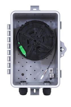
FieldShield ® Fiber Accessories
Pull Sock
Description
The FieldShield Pull Sock provides a pulling eye to install pre-terminated SC pushable assemblies and blunt drops using the integrated pull string that comes standard in all FieldShield Microducts. The pull sock grips the outer jacket of FieldShield Optical Cables by compressing while under tension.
YOURx Tools
Description
The YOURx Pulling Tool and protection tool provide a safe and reusable way to protect and pull the YOURx breakout. The FS-PROTECTYOURX will protect during the deployment of cable. Easily remove from the coupler by pushing the locking ring when ready to make the fiber connection. The FS-PUL-YOURX allows for up to 50 pounds of pulling force when using the stainless-steel pulling bullet on the tip of the assembly. Once completed pulling your FieldShield FLATdrop assembly, easily remove from tool by releasing the locking ring.
Pre-Configured Part Numbers
Part Number Description
FS-PUL-3-4MM FieldShield Pull Sock, for 3 to 5.5 mm FieldShield Pushable Fiber
FS-PUL-5-9MM FieldShield Pull Sock, for 5 to 9 mm FieldShield Pushable Fiber
FS-PROTECT-YOURX YOURx Protective Sleeve, 10 mm, without Pulling Carrot, Used During Deployment, Reusable
FS-PUL-YOURX YOURx Pulling Tool, 10 mm, with Stainless Steel Pulling Carrot, Reusable
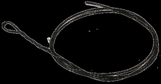
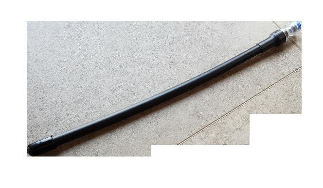
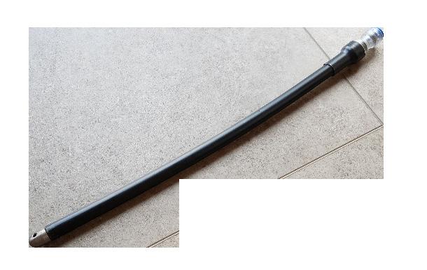
Rotary Fiber Tube Cutter
Description
Rotary Fiber Tube Cutter are designed to strip away the outer jacket from FieldShield Optical Fiber without damaging the fibers inside.
Pre-Configured Part Numbers
Part Number
FS-TCUT-3-4MM
Description
FieldShield Rotary Fiber Tube Cutter, for 3 mm to 5.5 mm jacket

Pull Sock
FS-PROTECT-YOURX
FS-PUL-YOURX
CraftSmart ®
Splice-On Connector (SOC)
Application
Fiber assemblies are used in a variety of carrier networks and private network environments. In some applications, the fiber assembly cannot be deployed with factory terminated connectors. In other instances, there may be a need for quick fiber restoration in the field. CraftSmart Splice-On Connectors are designed for these applications.
Description
In situations where a factory terminated fiber assembly isn’t possible, the CraftSmart SpliceOn Connector provides the solution for consistent performance. Common applications include field restoration of a broken fiber or when the customer is using media that is expensive and/or difficult to store. In these cases, the customer prefers to cut the media to exact length for his purposes and then use the CraftSmart Splice-On Connector. The Clearfield ® advantage is that the protection splice sleeve is directly under the boot, making the routing of the terminated end easier.

The CraftSmart Splice-On Connector is available in all industry standard connectors, including SC/UPC, SC/APC and LC/UPC. The Splice-On Connector meets, and even exceeds industry standard insertion and return loss. Pre-polished and pre-cleaved, the CraftSmart Splice-On Connector is packaged with all required connector components needed to splice a connector onto a 900 μm fiber in the field. CraftSmart Splice-on Connectors require the use of a fusion splicer with removable splice holders.
Features and Benefits
Integrity
• CraftSmart Splice-On Connector is available in all industry standard connectors
• Utilizes a fusion splice for minimal loss and long lasting dependability in any environment
• Meets or exceeds industry standard insertion loss and return loss Protection
• Individually packaged to protect pre-stripped and cleaved fiber during storage
• Fusion splice is protected by a fusion splice sleeve under a color coded boot
• Ferrules are made of durable Zirconia Access
• Compact 900 μm fusion splice design that reduces the overall footprint
• Pre-polished fiber end face and pre-stripped, pre-cleaved fiber ready to splice Investment
• Singlemode, multimode (62.5 μm and 50 μm) and laser optimized available
• Universal holder works with common industry fusion splice machines
CraftSmart ®
Splice-On Connector (SOC)
Technical Specifications
CraftSmart Splice-On Connector (SOC)
Ferrule Type Zirconica Pre-Polished Ferrules
Color Code Green Blue Beige Black Aqua
Industry Standards RoHS Compliant, Compliant to Telcordia GR-326
Compatible Splice Machines
Manufacturer Splicer Model
FIS Super Cougar All Versions
FSM-11(S/M) All Versions
FSM-12S
FSM-19S
AFL/Fujikura
All Versions
FSM-70S
Furukawa/Fitel
Sumitomo
INNO
CSM-SOC-FIBER HOLDER-01 All Versions
SM-SOC-FIBER HOLDER-02 All Versions
CSM-SOC-FIBER HOLDER-03 All Versions
FSM-17S/R SC and LC Only N/A
FSM-18S
FSM-41S
FSM-60 (S/R)
S122 (A/C/M)
S121 (A/M)
S123 (C/M)
S153
S177
S178A
SC, LC and ST Only
All Versions
S179, Ninja All Versions
Type-25e (U/S/M)
Type-39FH
Type-46
Type-65
Type-66
All Versions
CSM-SOC-FIBER HOLDER-04 All Versions
CSM-SOC-FIBER HOLDER-08 N/A
CSM-SOC-FIBER HOLDER-05 All Versions
Quantum (Q101-CA) N/A
IFS 10
IFS 15 All Versions
Greenlee 910FS All Versions
SM-SOC-FIBER HOLDER-06 N/A
CSM-SOC-FIBER HOLDER-07 N/A
CraftSmart ®
Splice-On Connector (SOC)
Pre-Configured Part Numbers
Part Number
CSM-LCU-SM-6PAK
CSM-SCA-SM-6PAK
CSM-SCU-SM-6PAK
Description
CraftSmart Splice-On Connectors, LC/UPC, singlemode, 6 pack
CraftSmart Splice-On Connectors, SC/APC, singlemode, 6 pack
CraftSmart Splice-On Connectors, SC/UPC, singlemode, 6 pack
FieldShield ® Pushable Optical Fiber
Application
Designed to simplify the placement of fiber, FieldShield Pushable Optical Fiber reduces the cost of any fiber deployment, while providing industry leading protection when mated with FieldShield Microducts. Pushable Optical Fiber is either pulled or pushed through microduct at turn-up, maximizing installation efficiency. In the event of a later fiber cut, the fiber can be easily pulled from the microduct. The duct is then repaired and a new FieldShield Pushable Assembly is pushed or pulled through the microduct for a fast and cost-effective restoration.
Description
FieldShield Pushable Optical Fiber is a durable and crush resistant product that is suitable for most indoor or outdoor environments. Manufactured using PBT jacketing, pushable optical fiber offers flexibility as well as resistance to chemicals. FieldShield Pushable Optical Fiber is typically recommended to be used in conjunction with FieldShield Microduct.
Features and Benefits Integrity
• Available in singlemode
• Supports all industry standard connectors Protection
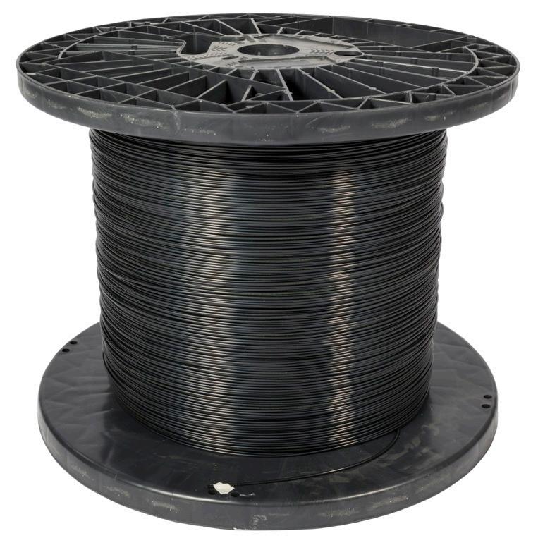
Available in 1, 2, 6, 12, 24 and 48 fiber counts
• Bend-insensitive (G.657.A2) fiber protects optical signal with minimal to zero attenuation down to a 10 mm radius
• Tough PBT jacketing provides high column strength and low coefficient of friction to maximize push and pull distances
• Lightweight and high crush resistance
• One and two fiber drops protected by water blocking Kevlar strength member
• 6 to 48-fiber utilize water blocking gel
Access
• Standard color is black
• Tech-friendly 250 μm fiber inside the outer jacket reduces splicing steps and installation costs
• Suitable for all types of indoor and outdoor implementations within a microduct Investment
• Pushes directly into a Clearview ® Cassette, FieldShield is optimized for placement alongside Clearfield ® FieldSmart ® fiber management platforms
• Quick and easy deployment allows capital investment to be aligned to customer take rates
• Available in multiple fiber counts up to 48 fibers
Recommended Push/Pull
FieldShield ®
Pushable Optical Fiber
Technical Specifications
FieldShield Pushable Optical Fiber
Fiber
Corning ClearCurve Optical Fiber or equivalent
Water Peak ZWP (Zero Water Peak)
Bend-Insensitive
Bend-Insensitive Fiber G.657.A2
Color Code TIA/EIA 598 (US Standard)
Fiber Count Any fiber count up to 48 fibers
Pushable Connectors FieldShield SC/UPC, SC/APC, Simplex and Duplex LC/UPC, Simplex and Duplex LC/APC, MPO
Standard Connectors SC/UPC, SC/APC, LC/UPC, LC/APC, HFOC SC/APC, MPO
Internal Fiber Size 250 μm
Outside Diameter 1 to 12-fiber : 0.118" (3 mm); 24-fiber: 0.156” (3.96 mm); 48-fiber :0.217” (5.51 mm)
Color Black Material
Operating
Installation Tension 20 lbf for 3 mm; 20 lbf for 4 mm
Markings Part number, lot number and footage markers every two feet (609.60 mm)
Pre-Configured Part Numbers
FS-CA1-001-8ZD-B XXXX FieldShield pushable optical fiber, 1-fiber (250 μm), singlemode, 3 mm jacket
FS-CA1-002-8ZD-B XXXX FieldShield pushable optical fiber, 2-fiber (250 μm), singlemode, 3 mm jacket
FS-CA1-006-8ZD-B XXXX FieldShield pushable optical fiber, 6-fiber (250 μm), singlemode, 3 mm jacket
FS-CA1-012-8ZD-B XXXX FieldShield pushable optical fiber, 12-fiber (250 μm), singlemode, 3 mm jacket
FS-CA1-024-8ZE-B XXXX FieldShield pushable optical fiber, 24-fiber (250 μm), singlemode, 4 mm jacket
FS-CA1-048-8ZF-B XXXX FieldShield pushable optical fiber, 48-fiber (250 μm), singlemode, 5.5 mm jacket
FieldShield ® FLEXdrop (UL Listed Plenum)
Application
Clearfield’s FieldShield FLEXdrop cable provides the most flexible option of our FieldShield product line. The OSP-rated PVDF jacketing allows for transition of FLEXdrop from the OSP environment directly into the inside plant, with the added benefit of being UL listed for plenum applications. FLEXdrop is either pulled or pushed through microduct at turn-up, maximizing installation efficiency. In the event of a later fiber cut, the fiber can be easily pulled from microduct. The duct is then repaired and a new FieldShield Pushable Assembly is pushed or pulled through the microduct for a fast and cost-effective restoration. Options for riser rated applications are also available.
Description
FieldShield FLEXdrop has more flexibility than standard FieldShield Optical Cable making it ideal for shorter drops where more handling and slack storage may be required. Whether it’s used indoor or outdoor, the flexibility of the jacket allows for deployment with reduced jacket memory and decreases the risk of kinking. While FLEXdrop is typically used in conjunction with FieldShield Microduct solutions, in some applications, it can be stapled directly to walls and ceilings or used on building wrap applications securing with crown T18 staples.
Features and Benefits Integrity
• Designed, tested and certified to Telcordia GR-20
• Available in singlemode
• Supports all industry standard connectors Protection
• UL listed for plenum and riser applications for single fiber only
• Passed UV testing and measurement standards per ASTM G155 for UL 1581
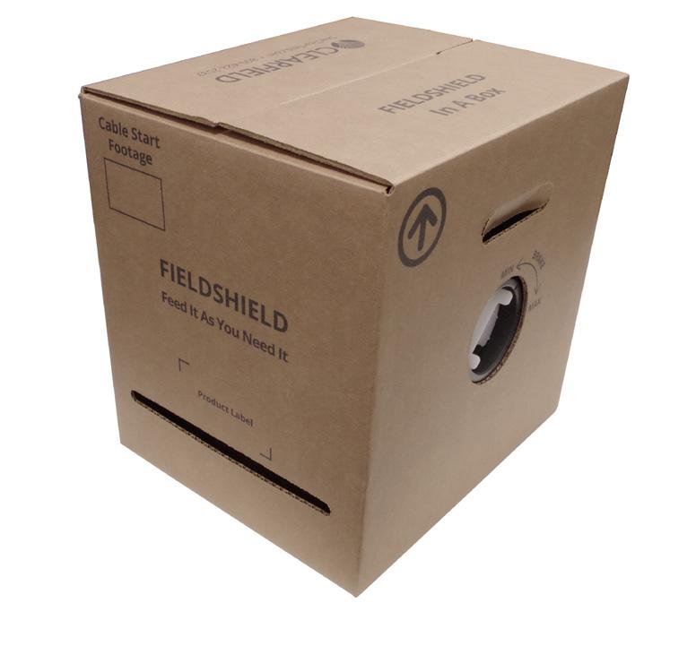
Available in single fiber count

• Bend-insensitive (G.657.A2) fiber protects optical signal with minimal to zero attenuation down to a 10 mm radius
• Staple-ready for walls, joists and around corners, with Crown T-18 staples
• Swellable yarns for water blocking capabilities Access
• Standard color is black with an option for off-white
• Suitable for all types of indoor and outdoor implementations (duct required for aerial and direct bury) Investment
• Quick and easy deployment allows capital investment to be aligned to customer take rates
FieldShield ® FLEXdrop (UL Listed Plenum)
Technical Specifications
FieldShield FLEXdrop
Fiber
Clad
Bend-Insensitive
Color Code TIA/EIA 598 (US Standard)
Fiber Count Single fiber
Pushable Connectors FieldShield SC/UPC and SC/APC
Standard
Mode Singlemode
Internal
Bend-Radius
Installation
Installation
Pre-Configure Part Numbers
FieldShield ® FLEXdrop SC Pushable Assemblies
(UL Listed Plenum/Riser)
Application
Designed to simplify the deployment of fiber, FieldShield FLEXdrop SC Pushable
Assemblies provide a tech-friendly field assembled connector that snaps together in seconds without jeopardizing fiber protection or optical reliability. FieldShield Pushable Assemblies greatly reduce installation costs for Fiber to the Home (FTTH) installations, business class services, cell backhaul or any other small count delivery application.
Description
FieldShield FLEXdrop SC Pushable Assemblies are factory terminated and polished SC and LC connectors designed to be terminated on simplex FieldShield Pushable Optical Fiber Assemblies. After being pushed or pulled through FieldShield Microduct, the smooth wall protective sleeve is easily removed and an outer housing is snapped into place. This creates an industry standard connector without mechanical or fusion splicing. All SC FieldShield Pushable Assemblies styles can be pushed/pulled in all FieldShield Microducts.
Features and Benefits
Integrity
• FLEXdrop Plenum fiber cable designed, tested and certified to Telcordia GR-20
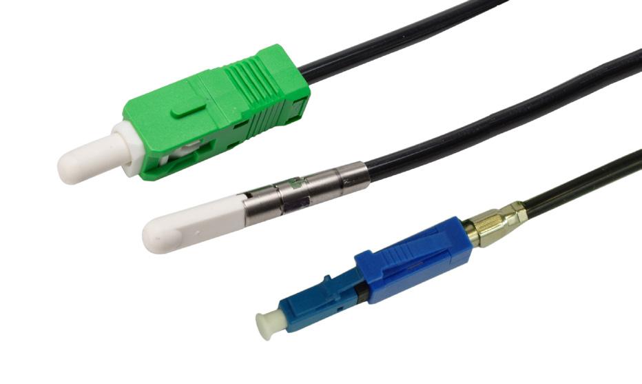
• FLEXdrop Plenum Terminations are designed, tested and certified to Telcordia GR-326
• Available in singlemode SC/UPC and SC/APC
Protection
• UL Listed for plenum and riser applications
• Smooth wall protective sleeve is easily removed and an outer housing is snapped into place
• Passed UV testing and measurements standards per ASTM G155 for UL 1581
• Option for FlexConnector in YOURx applications
Access
• Zirconia ceramic ferrule measuring 1.25 mm O.D.
• Tool-less installation
Investment
• Tech-friendly pre-terminated pushable connectors rapidly decrease deployment times and reduce installation costs by eliminating in-field splicing
• Pushed directly into a Clearview Cassette, FieldShield is optimized for placement alongside Clearfield’s FieldSmart ® fiber management platforms
Packaging
• FLEXdrop Plenum available in spools 75’ to 200’
• Zip-bag option
• FLEXdrop Riser only available in zip-bag

FieldShield ® FLEXdrop SC Pushable Assemblies (UL Listed Plenum/Riser)
Technical Specifications
Minimum Performance Specifications for Terminated Singlemode Connectors
Configured Part Numbers
Disclaimer/Note: Paper configurator shown is for reference only and should not be used to configure a saleable product configuration. All options shown on paper configurators may not be available or compatible with other options listed. Please contact your Clearfield representative for assistance in product configurations.
1 Select Cable Type
P = FLEXdrop Black Plenum
W = FLEXdrop White Plenum
R = FLEXdrop Black Riser
RW = FLEXdrop White Riser
2
1
2
Select Mode/Type
Accessories
Field Installable FlexConnector (FIFC)
B
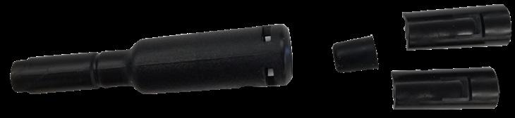
• Once the cable has been prepped with the FlexConnector, the 3 mm cable is sandwiched between the two retainer clips. The FlexConnector is then pushed and snapped together with the retainer clips, pinching the grommet seal for a water-tight assembly.
Field Installable
FlexConnector Pre-Configured Part Numbers
FS-FIFC-103-6PAK Field installable FlexConnector, 10 mm Port, 3 mm Cable, Black Grommet, 6 Pack
FS-FIFC-143-6PAK Field installable FlexConnector, 14 mm Port, 3 mm Cable, Gray Grommet, 6 Pack
FS-FIFC-144-6PAK Field installable FlexConnector, 14 mm Port, 4 mm Cable, Red Grommet, 6 Pack
Description
For field installed applications, these three kits allow a water-tight transition from 3 mm and 4 mm cable, into the FlexPort. The kits include enough parts for six tool-less installations.
FieldShield ® FLEXdrop Deploy Reel
Application
Due to the high variability of MDU architectures, extensive engineering has been required to ensure proper cable lengths for Fiber-to-the-Premise deployments. The 4.5” (114.30 mm) FieldShield FLEXdrop Deploy Reel minimizes pre-engineering because it allows FLEXdrop to be pulled from the reel directly to the access point. Once the pushable connector has reached its destination, the connector assembly is completed with the supplied connector housings and the connector is mated to the adapter. The remaining slack on the reel is pre-stored with no further slack management required. The terminated end on the reel is pre-tested, cleaned and mated in a Clearfield ® factory environment, leaving the technician to simply mate the patch cord to the adapter on the reel. The small form factor of the cable assembly and Deploy Reel allows the FLEXdrop to be pulled and slack stored from the customer demarcation point. As an ISP Cable, FLEXdrop reduces pre-engineering and onsite installation time for MDU and riser deployments.
Description
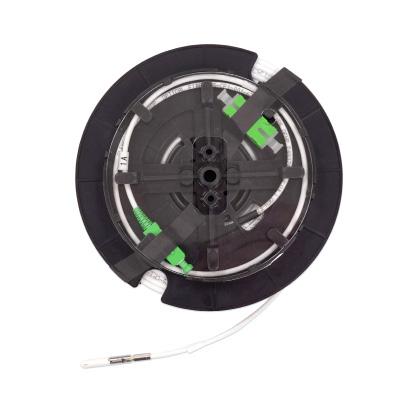
The FieldShield FLEXdrop Deploy Reel is a 4.5” x 2.125” (114.30 mm x 54.02 mm) spool designed to hold up to 100 feet (30.48 mm) of FieldShield FLEXdrop. The FLEXdrop 3mm fiber makes slack storage minimal and easy to accommodate, while the exceptional pull strength of FLEXdrop makes it craft-friendly and easy for the technician to handle without fear of fiber damage.
Features and Benefits
Integrity
• FLEXdrop fiber cable designed, tested and certified to Telcordia GR-20
• Terminations are designed, tested and certified to Telcordia GR-326
• Supports singlemode SC connectors Protection
• Deploying FLEXdrop with a FieldShield FLEXdrop Deploy Reel allows the installer to payout the exact amount of cable required and leave the remaining slack safely stored on the reel Access
• Straight forward, simple design means installation crews spend less time figuring out how to deploy
• Available in 50 and 100 foot lengths Investment
• Pre-terminated cable spools reduce upfront deployment costs by simplifying site survey inspections, reducing labor hours and streamlining cable deployment for SFU and MDU deployments
FieldShield ® FLEXdrop Deploy Reel
Technical Specifications
FieldShield FLEXdrop Deploy Reel
Dimensions 5.8” W x 2.125” H (147.30 mm x 54.02 mm)
Material Black Thermoplastic
Storage Temperature -40°F to 150°F (-40°C to 65°C)
Pullable Connectors FieldShield ® SC/APC and SC/UPC
Standard Connectors SC/APC, SC/UPC
Fiber FieldShield FLEXdrop 3mm, black and white
Cable Length 50, 75 and 100 foot lengths (15.24 m and 30.48 m)
Pre-Configured Part Numbers
Deploy

FieldShield ® FLEXdrop Deploy Reel With Extension Flanges
Technical Specifications
FieldShield FLEXdrop Deploy Reel
Dimensions 5.8” W x 2.125” H (147.30 mm x 54.02 mm)
Material Black Thermoplastic
Storage Temperature -40°F to 150°F (-40°C to 65°C)
Pullable Connectors FieldShield ® SC/APC and SC/UPC
Standard Connectors SC/APC, SC/UPC
Fiber FieldShield FLEXdrop 3mm
Cable Length 100, 150 and 200’ lengths (30.48 m, 45.72 m and 60.96 m)
Pre-Configured Part Numbers
Deploy Reel, with SC/APC
Patchcord FDR-C1FA-DZZ8-F
Configured Part Numbers
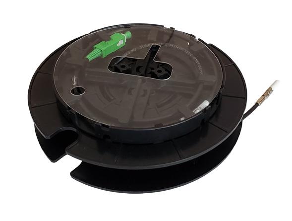
Disclaimer/Note: Paper configurator shown is for reference only and should not be used to configure a saleable product configuration. All options shown on paper configurators may not be available or compatible with other options listed. Please contact your Clearfield representative for assistance in product configurations.
Cable Deployment
Empty) = Standard
= Opposite
= Flange
= Opposite with Flange
FieldShield ® FLEXdrop Deploy Reel and Mini TAP Box
Description
The FieldSmart Mini TAP Box offers single or dual count fiber deployment in a discrete footprint and without sacrificing proper fiber management. The FieldSmart Mini TAP Box is designed to make FTTH more costeffective and efficient than previously thought possible. Standardizing on a craft-friendly, building block architecture reduces the operating costs of fiber deployments by reducing installation times and inventory carrying requirements.
Technical Specifications
FieldSmart Mini TAP
Dimensions
9” H x 6” W x 3.91” D (228mm x 152mm x 99.31mm)
Material UV Stabilized, Flame Retardant Polymer (PVC)
Mounting Option
Two exterior mounting ears
Rating NEMA 4, when combined with closure screws
Latching
Security
Access
Storage
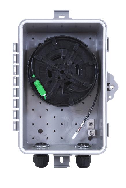
Two snap locks to ensure lid seals to base with integrated seal
Security screw with ability to secure padlock
Two multi-purpose entry/exit strain reliefs. 5 lb. max. retention force with flat drop down to 3mm cable.
50 feet of 3 mm cable (from flat drop) and 100 feet of FLEXdrop on Deploy Reel
Pre-Configured Part Numbers
Part Number
Description
FDRG-CDSC-HHLZ Deploy Reel Kit, Includes: Mini TAP Wall Box, StrongFiber Deploy Reel, Loaded with SC/APC Adapter and Simplex SC/APC to Pullable SC/APC 300 Feet, L-Bracket (No Adapter), Strain Relief
FDRG-CDF2-HHLZ Deploy Reel Kit, Includes: Mini TAP Wall Box, FLEXdrop Deploy Reel, Loaded with SC/APC Adapter and Simplex SC/APC to Pullable SC/APC 50 Feet, L-Bracket (No Adapter), Strain Relief
FieldShield ® FLEXdrop Deploy Reel and SCD TAP Box
Description
The lockable, NEMA-4 rated enclosure is compact with two bottom entry/exit points, making it ideal for a variety of applications. This enclosure can utilize the larger format FLEXdrop Deploy Reel with extension flanges for 100 and 200 feet applications.
Technical Specifications
Mounting Option
Two exterior mounting ears
Rating NEMA 4, when combined with closure screws
Latching
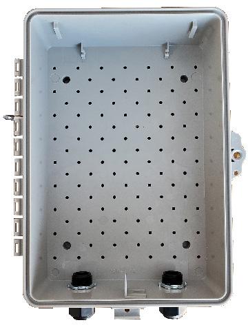


Two snap locks to ensure lid seals to base with integrated seal
Security Security screw with ability to secure padlock
Access
Two multi-purpose entry/exit strain reliefs. 5 lb. max. retention force with flat drop down to 3mm cable.
Storage 100 feet of 3 mm cable (from flat drop) and 200 feet of FLEXdrop on Deploy Reel
Pre-Configured Part Numbers
FieldShield ® Deploy Reel Kits for Mini TAP and SCD TAP
Configured Part Numbers
Disclaimer/Note: Paper configurator shown is for reference only and should not be used to configure a saleable product configuration. All options shown on paper configurators may not be available or compatible with other options listed. Please contact your Clearfield representative for assistance in product configurations.
B = FieldSmart SCD TAP Box
G = FieldSmart Mini TAP Box Select Box Style
Select Inside Connector
A = SC/UPC
C = SC/APC
E = LC/UPC
G = LC/APC
A = SC/UPC
B = Pullable SC/UPC
C = SC/APC
D = Pullable SC/APC
Z = None 2 3 4
Select Jacket
S = StrongFiber (Black)
F = FLEXdrop (Black)
FW = FLEXdrop (White)
Z = None
Select Left Exit/Entrance Port
G = Grommet
H = Strain Relief (Support FLATdrop, 10/6 Microduct, 3mm Jacket)
M = Adapter ¾
Z = None
7 Select Length
Select Right Exit/Entrance Port
G = Grommet
H = Strain Relief (Support FLATdrop, 10/6 Microduct, 3mm Jacket)
M = Adapter ¾”
S = Sealcon (½” - 12.7/10 Microduct)
Z = None
Select L-Bracket
A = SC/UPC
C = SC/APC
L = Empty
Z = None
9
Select Slack Spool
A = 1 x Storage Spool – 50 ft.
B = 1 x Storage Spool – 100 ft.
C = 2 x Storage Spool – 50 ft.
D = 2 x Storage Spool – 100 ft.
E = 1 x 50 ft. and 1 x 100 ft. Storage Spool
H = Mounting Plate
Z = None
Select Option (Left empty) = Standard
-F = Flange
-FS = Flange with Splice Chip
-N = Narrow Spool
-NR = Narrow and Opposite
-NRF = Narrow, Opposite with Flange
-R = Opposite
-RS = Opposite with Splice Chip
-RF = Opposite with Flange
-RFS = Opposite with Flange and Splice Chip
-S = Splice Chip

FieldShield ®
D-ROP - Direct Bury 10/6 mm
Application
Building upon the restoration promise of FieldShield Pushable Fiber, FieldShield D-ROP is a pre-connectorized drop cable delivered to market pre-placed in microduct. The microduct plugs directly into the FieldShield FlexPort, providing an air-tight, water-tight connection between the YOURx-TAP and the YOURx-Terminal.
Installed as a single-pass deployment, FieldShield D-ROP provides ease of restoration. In the event of a future fiber cut, a field technician easily identifies the cut area, and utilizes a simple coupler and a FieldShield Fiber Assembly to restore service.
Description
D-ROP cable presents the same footprint as a flat drop cable with the added advantage of being restorable. As with all FieldShield ducted solutions, fiber cuts are located and microduct is repaired with repair kit. A new pushable assembly is installed, minimizing costs and time to restore the service outage. It provides a completely protected pathway from the access point directly to the premise, business or antenna with the option for restoration after accidental fiber cut.
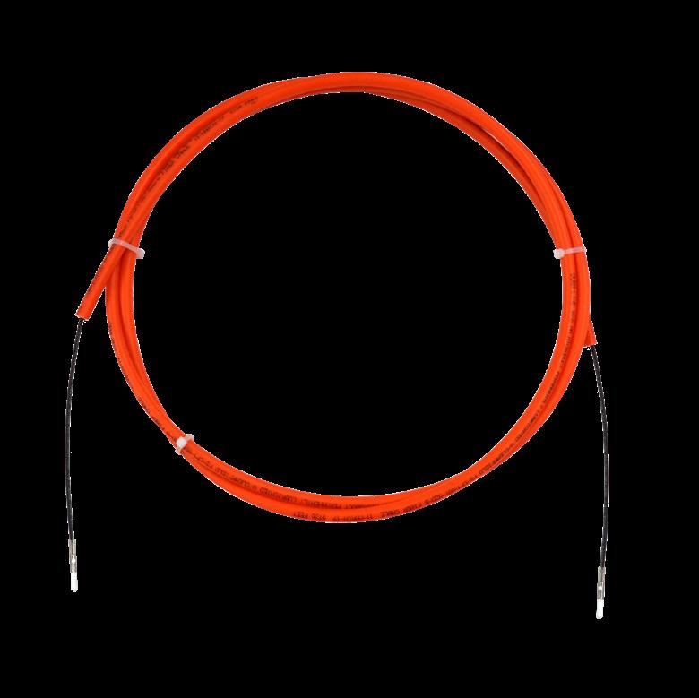
D-ROP does not have the slack storage challenges that a flat drop presents because the duct slack can be ring cut and removed leaving only the fiber assembly.
Features and Benefits Integrity
• Terminations are designed, tested and certified to Telcordia GR-326
• Fiber cable certified to Telcordia GR-20 and GR-409
• Duct is compliant to Telcordia GR-3155
• Available with singlemode fiber Protection
• FieldShield FlexConnector provides an air-tight, water-tight connection
• FieldShield Direct Bury Microduct has high tensile strength and crush resistance that withstands all types of implementations including open trenching, vibratory plowing and directional boring
• Duct is constructed from HDPE to prevent degradation Access
• Available pre-terminated with SC and LC
• Includes bend-insensitive fiber
• Microduct pushes directly into a YOURx-Terminal or YOURx-TAP
• Integrated tone wire simplifies ground locating in direct bury applications
• Industry standard orange provides high visibility for direct bury applications Investment
• Pre-connectorized for a labor-lite, plug-and-play installation
FieldShield ® D-ROP
- Direct
Bury 10/6
mm
Technical Specifications
FieldShield D-ROP - Direct Bury
Outside Diameter 0.394” (10.01 mm); Oversheathed Toneable 0.50” (12.70 mm)
Inside Diameter 0.246” (6.25 mm)
Installation Tension 340 lbf
Bend Radius Non-toneable: 6” (152.40 mm) Radius Minimum; Toneable: 7” (177.80 mm) Radius Minimum
Material High Density Polyethylene (HDPE)
Operating Temperature -40°F to 176°F (-40°C to 80°C)
Installation Temperature -14°F to 158°F (-26°C to 70°C)
Color Orange
Tone Wire Insulated Copper (Tone Only)
Tone Wire Diameter 0.032” (0.813 mm)/20 AWG (Tone Only)
Configured Part Numbers
Disclaimer/Note: Paper configurator shown is for reference only and should not be used to configure a saleable product configuration. All options shown on paper configurators may not be available or compatible with other options listed. Please contact your Clearfield representative for assistance in product configurations.
Select Duct Construction
A = Aerial
D = 10/6 Direct Bury Non-Toneable
P = 8.5/6 Plenum
R = 8.5/6 Riser
T = 10/6 Direct Bury Toneable
Select Duct Color
2 = Orange
8 = Black
C = Beige
Select Fiber Type
1 = Singlemode 900 um
2 = Riser 2mm
3 = FLEXdrop 3mm
S = Singlemode StrongFiber
Select Upjacketing
B = 2mm Ruggedized
D = 3mm Ruggedized Z = N/A
Select Connector #2
B = Pushable SC/UPC
D = Pushable SC/APC
Z = Pigtail
Select Breakout
3 = 12" for FlexPort P = Pulling Eye
Z = NA/Pigtail
Select Upjacketing
B = 2mm Ruggedized
D = 3mm Ruggedized
Z = N/A
Select Length (XXXXF)
FieldShield ®
D-ROP - Plenum and Riser Rated 8.5/6 mm
Application
Building upon the restoration promise of FieldShield Pushable Fiber, FieldShield D-ROP is a pre-connectorized drop cable delivered to market pre-placed in microduct. The microduct plugs directly into the FieldShield FlexPort.
Installed as a single-pass deployment, FieldShield D-ROP provides ease of restoration. In the event of a future fiber cut, a field technician easily identifies the cut area, and utilizes a simple coupler and a FieldShield Fiber Assembly to restore service.
Description
D-ROP cable presents the same footprint as a flat drop cable with the added advantage of being restorable. As with all FieldShield ducted solutions, fiber cuts are located and microduct is repaired with repair kit. A new pushable assembly is installed, minimizing costs and time to restore the service outage. It provides a completely protected pathway from the access point directly to the premise, business or antenna with the option for restoration after accidental fiber cut.
D-ROP does not have the slack storage challenges that a flat drop presents because the duct slack can be ring cut and removed leaving only the fiber assembly.
Features and Benefits Integrity
• Terminations are designed, tested and certified to Telcordia GR-326
• Fiber cable certified to Telcordia GR-20 and GR-409
• Duct is compliant to Telcordia GR-3155
• UL-2024 Listed
Protection
• Riser Rated 8.5/6 mm Microduct has high tensile strength and crush resistance
• Designed for applications designated as riser air space Access
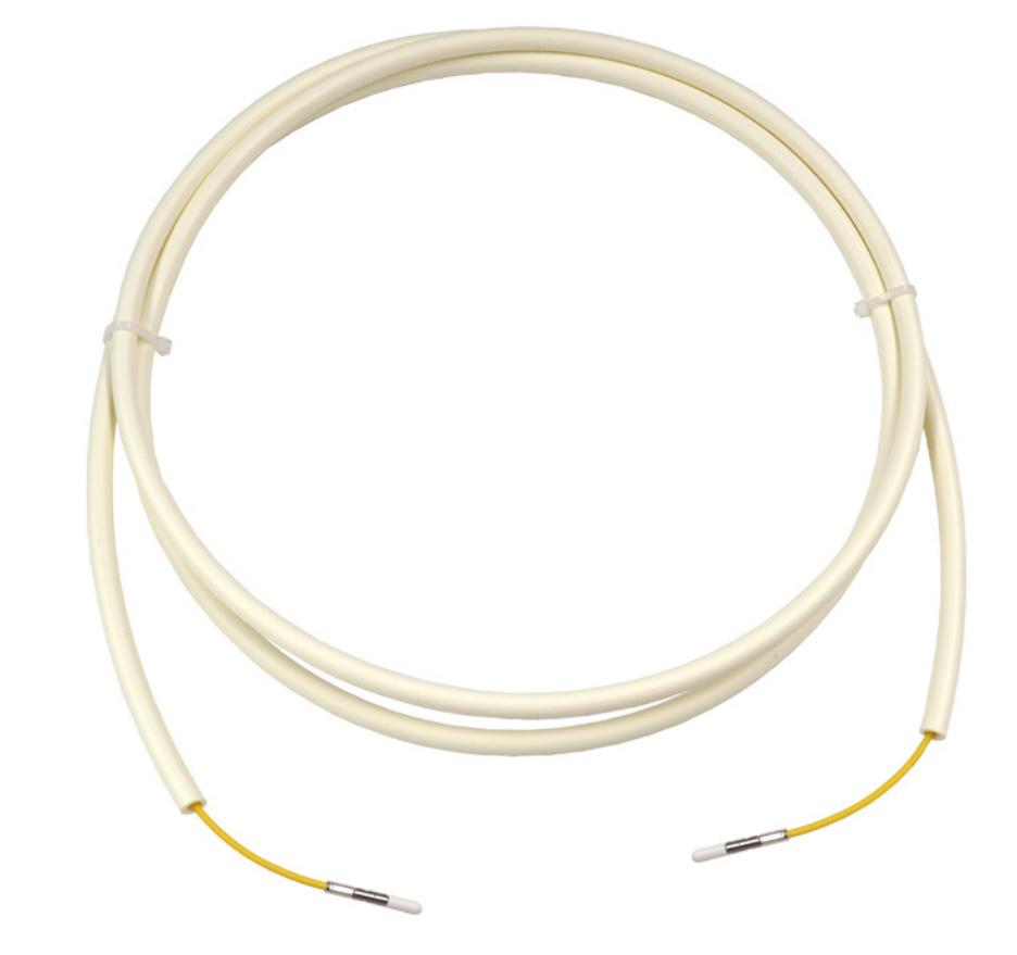
• Industry standard beige provides high visibility for indoor installation applications in existing conduit and by itself Investment
• Pre-connectorized for a labor-lite, plug-and-play installation
FieldShield ®
D-ROP - Plenum and Riser Rated 8.5/6 mm
Technical Specifications
FieldShield D-ROP - Riser Rated
Outside Diameter
(8.5 mm) Inside
0.23” (5.9 mm)
Installation Tension 96 lbf
Min. Bend Radius 76.2 mm/3 mm
Material Thermoplastic
Operating
-40°F to 176°F (-40°C to 80°C)
Installation Temperature -14°F to 158°F (-26°C to 70°C)
Color Beige
Tone Wire N/A
Configured Part Numbers
Disclaimer/Note: Paper configurator shown is for reference only and should not be used to configure a saleable product configuration. All options shown on paper configurators may not be available or compatible with other options listed. Please contact your Clearfield representative for assistance in product configurations.
FieldShield ®
D-ROP 7/3.5 mm
Application
Building upon the restoration promise of FieldShield Pushable Fiber, FieldShield D-ROP is a pre-connectorized drop cable delivered to market pre-placed in a 7 mm microduct. The FieldShield FlexConnector snaps into the FieldShield FlexPort, providing an air-tight, watertight connection between the YOURx-TAP and the YOURx-Terminal.
Installed as a single-pass deployment, FieldShield D-ROP provides ease of restoration. In the event of a future fiber cut, a field technician easily identifies the cut area, and utilizes a simple coupler and a FieldShield Fiber Assembly to restore service.
Description
D-ROP cable presents the same footprint as a flat drop cable with the added advantage of being restorable. As with all FieldShield ducted solutions, fiber cuts are located and microduct is repaired with repair kit. Blunt fiber is then pulled and terminated with a spliceon connector, minimizing costs and time to restore the service outage. The pre-installed FlexConnector is plugged directly into the FlexPort opening of the YOURx-Terminal or YOURx-TAP, providing a completely protected pathway from the access point directly to the premise, business or antenna with the option for restoration after accidental fiber cut.
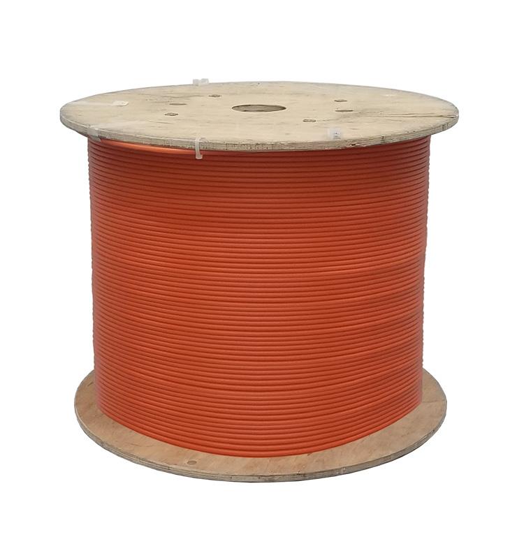
D-ROP does not have the slack storage challenges that a flat drop presents because the duct slack can be peeled or removed leaving only the fiber assembly.
FlexConnector Options
• Factory Installed: the connector is shipped permanently installed on the pre-connectorized cable.
• Field Installable: the connector is shipped separately to be installed in the field. This is an ideal solution for eliminating excess slack storage when standard cable lengths are used for custom drop distances. The FlexConnector can be field installed on the preconnectorized cable (full plug-and-play) or blunt cable followed by a splice-on connector.
Features and Benefits
Integrity
• Duct is compliant to Telcordia GR-3155
• Available with singlemode fiber Protection
• FieldShield FlexConnector provides an air-tight, water-tight connection
• FieldShield Direct Bury Microduct has high tensile strength and crush resistance that withstands all types of implementations including open trenching, vibratory plowing and directional boring
• Duct is constructed from HDPE to prevent degradation
Access
• Available pre-terminated with SC and LC or bulk for field installation
• Option for splice-on connector (utilizing fiber matrix 850 µm)
• Includes bend-insensitive fiber
• The FlexConnector installed onto microduct pushes directly into a YOURx-Terminal or YOURx-TAP
• Integrated tone wire simplifies ground locating in direct bury applications
• Industry standard orange provides high visibility for direct bury applications
• Available for aerial applications
Investment
• Available in bulk or pre-connectorized for a labor-lite, plug-and-play installation
• FieldShield FlexConnector available in 4 packs for field installations
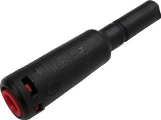
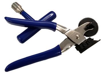
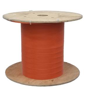
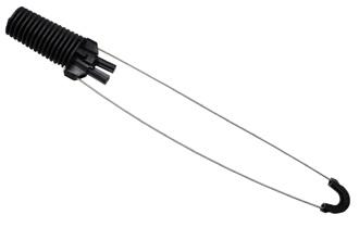
FieldShield ® D-ROP
7/3.5 mm
Technical Specifications
FieldShield D-ROP
Outside Diameter 0.276” (7.01 mm)
Inside Diameter 0.146” (3.71 mm)
Material HDPE
Connector Style SC and LC
Operating Temperature -40°F to 176°F (-40°C to 80°C)
Stringing Tension To local regulations. Recommended not to exceed 0.2 KN
Min. Bend Radius 4.72” (119.89 mm)
Rated Cable Load 270 lbf (1.2 KN)
Duct Color Orange (Direct Bury with tone) or Black (Aerial)
Tone Wire Copper coated steel wire (Direct Bury only)
Markings Part number, lot number, footage markers every foot
Breakout Length 12 inches (304.80 mm)
Accessories
• Field Installable FlexConnector (FSD-FIFC-4PAK)
- Installer cuts duct to desired length in the field using a rotary cutter, then snaps on the FlexConnector. After fusing on the standard connector and passing through the FlexPort, the outer housing is attached and connected to the adapter.
• D-ROP Opener: splitter tool with 7 mm OD (FS-DUCT-OPENER)
• D-ROP Deadend (FS-DEADEND-LG7)
Configured Part Numbers
Disclaimer/Note: Paper configurator shown is for reference only and should not be used to configure a saleable product configuration. All options shown on paper configurators may not be available or compatible with other options listed. Please contact your Clearfield representative for assistance in product configurations. Factory
FieldShield ®
D-ROP 7/3.5 mm
Pre-Configured Part Numbers
Field-Installed Connectors
Part Number Description
FS-MED-001-T-207-3280F Bulk D-ROP, direct bury, toneable, orange, 7 mm O.D., 3280 foot (999.75 m) spool
FS-MEA-001-NT-807-3280F Bulk D-ROP, aerial, black, 7 mm O.D., 3280 foot (999.75 m) spool
FSD-FIFC-4PAK Field installable FlexConnector in 4 pack
FSD-FIFC-SCA-4PAK Field installable FlexConnector with splice-on SC/APC connectors, 4 pack
FieldShield ® FLATdrop
Application
In addition to our industry standard fiber flat drop, Clearfield offers additional FieldShield FLATdrop options designed to save contractors and installers time and space in almost any deployment environment. The peelable outer sheath of FieldShield FLATdrops allow for easy access to the inner fiber elements (900um) and each offer a large selection of connector types in a pre-connectorized solution while allowing for up to 100 feet of compact fiber slack storage.
Clearfield’s suite of flat drop solutions effectively meet the unique needs of your network deployment.
• FieldShield Small Form Factor FLATdrop 900μm Peelable is a uniquely smaller footprint flat drop solution for the access portion of a FTTH or FTTB network. The small format handles more easily than traditional flat drop, allowing for less coiled storage space in outdoor storage. When the jacket is snipped and easily peeled away, the exposed 900μm subunit stores neatly on the compact FieldShield slack
reel.
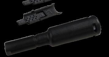
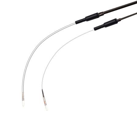
3mm 900μm
This small form factor FLATdrop is enabled with a pushable SC connector, allowing for placing and pushing through an existing pathway, in addition to the traditional deployments of direct bury or placing aerially.
• FieldShield FLATdrop 3mm Peelable is a drop cable solution for the access network such as FTTH and FTTB. By simply peeling back the outer jacket to expose the 3mm sub-unit, storage of excess cable is easily managed and stored on FieldShield slack reels.
All FieldShield FLATdrop cables are factory preconnectorized for fast terminal connection. At the access point, when utilizing YOURxTerminal, simple plug-and play connectivity is achieved by incorporating a 10mm FieldShield FlexConnector. For use with standard TAP Boxes, FLATdrop breakouts secure into multi-purpose strain relief access points.
Suite of products options includes:
• jacket construction in either toneable or non-toneable
• up-jacketing with or without a rip cord (in 3mm version)
FieldShield FlexConnector
FieldShield ® FLATdrop
Description
The FieldShield FLATdrop suite offers the first pre-connectorized flat drop style cable to provide hardened environmental performance on a peelable flat drop style cable without the added cost or dependency on the market’s existing bulky connector. Connectivity to access terminals is achieved through the innovative FlexConnector, which snaps into the YOURx-Terminal, providing an air-tight and water-tight connection.
FlexConnector Options
• Factory Installed: the FlexConnector is shipped permanently installed on the pre-connectorized cable.
• Field Installable: the FlexConnector is shipped separately to be installed in the field over a Pushable SC. This is an ideal solution for eliminating excess slack storage when standard cable lengths are used for custom drop distances. The FlexConnector can be field installed on the pre-connectorized cable (full plug-and-play) or blunt cable followed by a splice-on connector.
Features and Benefits
Integrity
• Available in singlemode
• FlexConnector is designed, tested and certified to GR-771
• Terminations are designed, tested and certified to GR-326 Protection
• FlexConnector provides an air-tight, water-tight connection
• FLATdrop peelable cable allows for the outer jacket to be stripped back to expose the more flexible 3mm sub-unit or 900um sub-unit, easing storage of terminated ends Access
• Flat drop cable construction allows for installation in direct bury and aerial applications
• Pre-terminated with an SC, LC or MPO connector or with pigtail for customer choice application
• Toneable cables allow for traceability Investment
• Leveraging the low cost of a traditional optical flat drop cable with option for plug-and-play field terminations
• Quick and easy deployment allows capital investment to be aligned to customer take rates
• FieldShield FlexConnector available in bulk packs for field installations
Technical Specifications
FieldShield FLATdrop
Core Size and Type
Cable Types Flat Drop Cable (Dielectric/Toneable)
Connector Type SC, LC or MPO (only for Standard Flat Drop multi-fiber configuration)
Breakout Length 12 inches (304.80 mm)
Operating Temperature -40°F to 176°F (-40°C to 80°C)
Color Black Jacket and White Sub-unit
Markings Part number, lot number, footage markers every two feet (609.60 mm)
FieldShield ® FLATdrop
Technical Specifications - Pole to Pole Span
* Max pulling force on connector “W2” is 70 lbs. To obtain 100 lbs., pull on opposite end with pull sock.
Configured Part Numbers
Disclaimer/Note: Paper configurator shown is for reference only and should not be used to configure a saleable product configuration. All options shown on paper configurators may not be available or compatible with other options listed. Please contact your Clearfield representative for assistance in product configurations.
SC and LC Factory Installed Connector
Select Jacket Construction
T = Peelable 3mm Non-toneable (Non-rated)
U = Peelable 3mm Toneable (Non-rated)
3 = Peelable SFF 900µm Non-Toneable (Non-rated)
4 = Peelable SFF 900µm Toneable (Non-rated)
Select Connector #1
A = SC/UPC D = SC/APC Pushable
B = SC/UPC Pushable W = HFOC SC/APC
C = SC/APC W2 = HFOC SC/APC for 900um
1 2 4 5 1 2 3
Select Breakout
Q = YOURx (Factory Installed)
Z = N/A for HFOC or Pigtail
1 = YOURx (Ship-along)
3 = Minimum Required
Configured Part Numbers
Select Jacket Construction
Select Fiber Count
Select Connector #1
N = Pushable MPO Male
P = Pushable MPO Female
5 = MPO Male
6 = MPO Female
4 Select Upjacketing
A = 900 µm
K = 3mm Subunit (Rip Cords)
N = 3mm Subunit (No Rip Cords)
Z = N/A 6 Select Breakout
5
Select Connector #2
Select Upjacketing 6 7
A = SC/UPC G = LC/APC
B = SC/UPC Pushable W = HFOC SC/APC
C = SC/APC W2 = HFOC SC/APC for 900um
D = SC/APC Pushable Z = Pigtail
E = LC/UPC
B = 1 Meter P = Pulling Eye
C = ½ Meter Q = YOURx
Z = N/A for HFOC or 3 = Minimum Required Pigtail
A = 900 µm
K = 3mm Subunit (Rip Cords)
N = 3mm Subunit (No Rip Cords)
Z = N/A
XXXM =
Select Connector #2
Pushable
Pigtail
Select Breakout #2
Select Upjacketing
D = 3mm Ruggedized
Z = N/A
FieldShield ® FLATdrop
Accessories
Part Number
Description
FSH-FIFC-4PAK Field installable FlexConnector for peelable 3mm, for 4 terminations
FSP-FIFC-6PAK Field installable FlexConnector for peelable 900 µm, for 6 terminations
FS-PUL-YOURX YOURx Pulling Tool, 10 mm, with Stainless Steel Pulling Carrot, Reusable
FS-PUL-5-9MM Pull Sock, 5-9mm, cable, small format cable, reusable
FS-PROTECT-YOURX YOURx Protective Sleeve, 10 mm, without Pulling Carrot, Used During Deployment, Reusable
• Field Installable FlexConnector (FSH-FIFC-4PAK) and FSP-FIFC-4PAK for 900 µm assembly
- Once the cable has been prepped, the flat cable is sandwiched between the two retainer clips, pinched into place and then the FlexConnector is pushed and snapped together with the retaining clips
• When using FS-PUL-5-9MM on pushable connector end on small format FLATdrop:
- Pulling Eye Loop = 50 lb. max.
- Pull Sock = 100 lb. pull force
- See QR code for installation method video

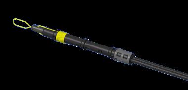

Scan for FieldShield Small Form Factor Video.
Scan for Pulling Bullet Video.
FieldShield ®
Field Installable FlexConnector (FIFC)
Application
The FieldShield Field Installable FlexConnector (FIFC) is an easy, tool-less way to create a water-tight seal when connecting FieldShield drop cable assemblies to the FieldShield FlexPorts in the YOURx-Terminal and YOURx-TAP in the OSP or building demarc.
Features and Benefits
Integrity
• FlexConnector designed and tested using FieldShield Drop Cables Protection
• FieldShield FlexConnector provides an air-tight, water-tight connection Access
• Suitable for all types of indoor and outdoor implementations utilizing the FlexPort Investment
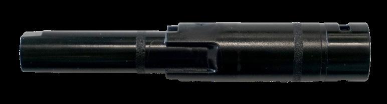
• Quick and easy deployment allows capital investment to be aligned to customer take-rates
FieldShield 3mm and 4mm Cable
Description
The Field Installable FlexConnector for FieldShield 3 and 4 mm cables completes the field installation options for FieldShield drop cable assemblies. Available for 3 mm cable with either a 10 or 14 mm FlexConnector or a 4 mm cable with a 14 mm FlexConnector, the simple design allows for installation in the field, without the need for heat shrink or specialized tools. Preconnectorized, pushable SC or MPO connectors, as well as pullable LC connectors, will easily pass through the FlexConnector.
Pre-Configured Part Numbers
FS-FIFC-103-6PAK Field installable FlexConnector, 10 mm Port, 3 mm Cable, Black Grommet, 6 Pack
FS-FIFC-143-6PAK Field installable FlexConnector, 14 mm Port, 3 mm Cable, Gray Grommet, 6 Pack
FS-FIFC-144-6PAK Field installable FlexConnector, 14 mm Port, 4 mm Cable, Red Grommet, 6 Pack
FieldShield FLATdrop
Description
FieldShield FLATdrop is the first pre-connectorized flat drop style cable to provide hardened environmental performance on a flat drop style cable without the added cost or dependency on the market’s existing bulky connector. Connectivity to access terminals is achieved through the innovative FlexConnector, which snaps into the YOURx-Terminal and YOURx-TAP, providing an air-tight and water-tight connection.
Pre-Configured Part Numbers
Part Number Description
FSH-FIFC-4PAK Field installable FlexConnector 3mm with pieces for 4 terminations
FSH-FIFC-SCA-4PAK Field installable FlexConnector splice-on SCA connectors and pieces for 4 terminations
FSP-FIFC-6PAK Field installable FlexConnector, 900 um, 6 Pack
Direct Bury 10/6 mm Microduct FieldShield
Application
Simplifying the placement of fiber, while providing protection from harsh environmental elements, FieldShield Direct Bury 10/6 mm Microduct is specifically designed for applications requiring a small heavy duty drop feed. Rugged crush resistance protects FieldShield Direct Bury Microduct from the rigors of all industry standard ground deployment methods, while rigid column strength allows microducts to be deployed through occupied duct previously thought exhausted. Direct Bury 10/6 mm Microduct has an outer diameter of 10 mm and an inner diameter of 6 mm.
Description
FieldShield Direct Bury 10/6 mm Microduct is a durable and crush resistant micro-conduit designed to increase the protection of fiber while decreasing installation and maintenance expenses. Manufactured using high density polyethylene (HDPE), FieldShield Direct Bury Microduct offers superior durability and protection.
Features
and Benefits
Integrity
• Compliant to Telcordia GR-3155
Protection
• Quick and easy to install

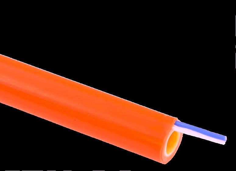

• Direct Bury Microduct has high tensile strength and crush resistance that withstands all types of ground implementations including open trenching, vibratory plowing, micro-trenching and directional boring
• Made from HDPE to prevent degradation
Access
• Optional external tone wire simplifies ground locating
• Industry standard orange provides high visibility for direct bury applications
• Standard nylon pull string simplifies deployment of fiber
• Smooth core slip lining reduces drag co-efficient enabling fiber to be pushed or pulled with minimal resistance
• Optional black color available to couple direct bury orange to a more aesthetically pleasing black color as it transitions above ground on the side of a living unit
Investment
• Maximizes capacity of existing conduit previously considered exhausted
• Provides industry leading protection for “last mile” feeds
FieldShield ®
Direct Bury 10/6 mm Microduct
Technical Specifications
FieldShield Direct Bury 10/6 mm Microduct
Length 2,000 feet (609.60 m) per spool (-0 / +5%)
Outside Diameter 0.394" (10.01 mm); Oversheathed Toneable 0.50” (12.70 mm)
Inside Diameter
0.246" (6.25 mm)
Wall Thickness 0.074" (1.88 mm)
Slip Layer Minimum 0.004" (0.102 mm)
Ovality ≤ 5%
Installation Tension 340 lbf
Bend-Radius Non-toneable: 6" (152.40 mm) radius minimum; Toneable: 7” (177.80 mm) radius minimum
Material High Density Polyethylene (HDPE)
Operating Temperature -40°F to 176°F (-40°C to 80°C)
Installation Temperature -14°F to 158°F (-26°C to 70°C)
Color Orange and Black
Tone Wire Insulated Copper
Tone Wire Diameter 0.032” (0.813 mm) / 20 AWG
Markings Part number, lot number, footage markers every two feet (609.60 mm)
Spool Size 12” ID x 24” OD x 20” W (304.80 mm x 609.60 mm x 508.00 mm)
Weight Non-toneable: 71 lbs (32.21 kg); Toneable: 78 lbs (35.38 kg)
Pre-Configured Part Numbers
Part Number Description
FS-DED-NT-210-PS-2000F FieldShield Microduct, 10 mm, direct bury, non-toneable, orange, 2000 feet (609.60 m)
FS-MEO-T-210-2000F FieldShield Microduct, 10 mm, direct bury, oversheathed toneable, orange, 2000 feet (609.60 m)
FS-MED-NT-810-2000F FieldShield Microduct, 10 mm, direct bury, non-toneable, black, 2000 feet (609.60 m)
FieldShield ®
Direct Bury 14/10 mm Microduct
Application
Simplifying the placement of fiber, while providing protection from harsh environmental elements, FieldShield Direct Bury 14/10 mm Microduct is specifically designed for applications requiring a small heavy duty drop feed. Rugged crush resistance protects FieldShield Direct Bury Microduct from the rigors of all industry standard ground deployment methods, while rigid column strength allows microducts to be deployed through occupied duct previously thought exhausted. Direct Bury 14/10 mm Microduct has an outer diameter of 14 mm and an inner diameter of 10 mm.
Description
FieldShield Direct Bury 14/10 mm Microduct is a durable and crush resistant micro-conduit designed to increase the protection of fiber while decreasing installation and maintenance expenses. Manufactured using high density polyethylene (HDPE), FieldShield Direct Bury 14/10 mm Microduct offers superior durability and protection.
Features and Benefits Integrity
• Compliant to Telcordia GR-3155 Protection
• Quick and easy to install


• Direct Bury Microduct has high tensile strength and crush resistance that withstands all types of ground implementations including open trenching, vibratory plowing, micro-trenching and directional boring
• Made from HDPE to prevent degradation Access
• Optional external tone wire simplifies ground locating
• Industry standard orange provides high visibility for direct bury applications
• Standard nylon pull string simplifies deployment of fiber
• Smooth core slip lining reduces drag co-efficient enabling fiber to be pushed or pulled with minimal resistance Investment
• Maximizes capacity of existing conduit previously considered exhausted
• Provides industry leading protection for “last mile” feeds
FieldShield ®
Direct Bury 14/10 mm Microduct
Technical Specifications
FieldShield Direct Bury 14/10 mm Microduct
Length
Outside Diameter
Inside Diameter
Non-toneable: 1,500 feet (457.20 m) per spool; Toneable: 1,250 feet (381.00 m) per spool
Non-toneable: 0.551” (14.00 mm); Toneable: 0.66” (16.76 mm)
0.390" (9.91 mm)
Wall Thickness 0.079" (2.01 mm)
Slip Layer Minimum 0.004" (0.102 mm)
Ovality ≤ 5%
Installation Tension
Non-toneable: 264 lbf; Toneable: 346 lbf
Bend-Radius Non-toneable: 8” (203.20 mm) radius minimum; Toneable: 10” (254.00 mm) radius minimum
Material High Density Polyethylene (HDPE)
Operating Temperature -40°F to 176°F (-40°C to 80°C)
Installation Temperature -14°F to 158°F (-26°C to 70°C)
Color Orange
Tone Wire Insulated Stranded Copper
Tone Wire Diameter 0.032” (0.813 mm) / 20 AWG
Markings Part number, lot number, footage markers every two feet (609.60 mm)
Spool Size 12” ID x 24” OD x 20” W (304.80 mm x 609.60 mm x 508.00 mm)
Weight Non-toneable: 72 lb (32.66 kg); Toneable: 95 lbs (43.09 kg)
Pre-Configured Part Numbers
Part Number Description
FS-DED-NT-214-PS-1500F FieldShield microduct, 14 mm, direct bury, non-toneable, orange, 1500 feet (457.20 m)
FS-DEO-T-214-PS-1250F FieldShield microduct, 14 mm, direct bury, oversheathed toneable, orange, 1250 feet (381.00 m)
FieldShield
®
Direct Bury 14/10 mm Black Microduct
Application
Simplifying the placement of fiber, while providing protection from harsh environmental elements, FieldShield Direct Bury 14/10 mm Black Microduct is specifically designed for applications requiring a small heavy duty drop feed. Rugged crush resistance protects FieldShield Direct Bury Microduct from the rigors of all industry standard ground deployment methods, while rigid column strength allows microducts to be deployed through occupied duct previously thought exhausted. Direct Bury 14/10 mm Black Microduct has an outer diameter of 14 mm and an inner diameter of 10 mm.
Description
FieldShield Direct Bury 14/10 mm Black Microduct is a durable and crush resistant microconduit designed to increase the protection of fiber while decreasing installation and maintenance expenses. Manufactured using high density polyethylene (HDPE), FieldShield Direct Bury 14/10 mm Microduct offers superior durability and protection.
Features and Benefits
Integrity
• Compliant to Telcordia GR-3155 Protection
• Quick and easy to install
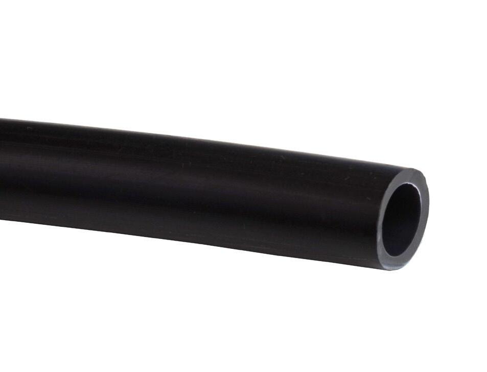
• Direct Bury Microduct has high tensile strength and crush resistance that withstands all types of ground implementations including open trenching, vibratory plowing, micro-trenching and directional boring
• Made from HDPE to prevent degradation Access
• Standard nylon pull string simplifies deployment of fiber
• Ribbed core slip lining reduces drag co-efficient enabling fiber to be pushed or pulled with minimal resistance Investment
• Maximizes capacity of existing conduit previously considered exhausted
• Provides industry leading protection for “last mile” feeds
FieldShield ®
Direct Bury 14/10 mm Black Microduct
Technical Specifications
FieldShield Direct Bury 14/10 mm Black Microduct
Length 4,922 feet (1500.23 m) per spool
Outside Diameter
Inside Diameter
0.551” (14 mm +/- 0.2 mm)
0.390" (9.91 mm)
Wall Thickness 0.079” (2 mm +/- 0.2 mm)
Installation Tension Non-toneable: 264 lbf; Toneable: 346 lbf
Bend-Radius 8” (203.20 mm) radius minimum
Material High Density Polyethylene (HDPE)
Operating Temperature -40°F to 176°F (-40°C to 80°C)
Installation Temperature -14°F to 158°F (-26°C to 70°C)
Color Black
Markings Part number, lot number, footage markers every two feet (609.60 mm)
Spool Size 40” OD x 24” W (1016.00 mm x
Configured Part Numbers
FieldShield ®
Plenum 10/6 mm Microduct
Application
Plenum rated microducts provide a self extinguishing raceway to protect and deploy optical fiber in airspaces, raised floors and other indoor applications designated as plenum air spaces. Plenum 10/6 mm Microduct has an outer diameter of 10 mm and an inner diameter of 6.9 mm.
Description
FieldShield Plenum 10/6 mm Microduct is a durable, polyvinylidene difluoride (PVDF) crush resistant microduct suitable for protecting fiber in any indoor application. Easily mated with an airtight and waterproof coupler, FieldShield Plenum Microducts integrate with direct bury and aerial microducts creating a single and continuous pathway from outside plant to inside plant environments.
Features and Benefits
Integrity
• Compliant to Telcordia GR-3155
• Conforms to UL-2024. ETL listed.
Protection
• Plenum rated material self-extinguishes flame and does not reignite
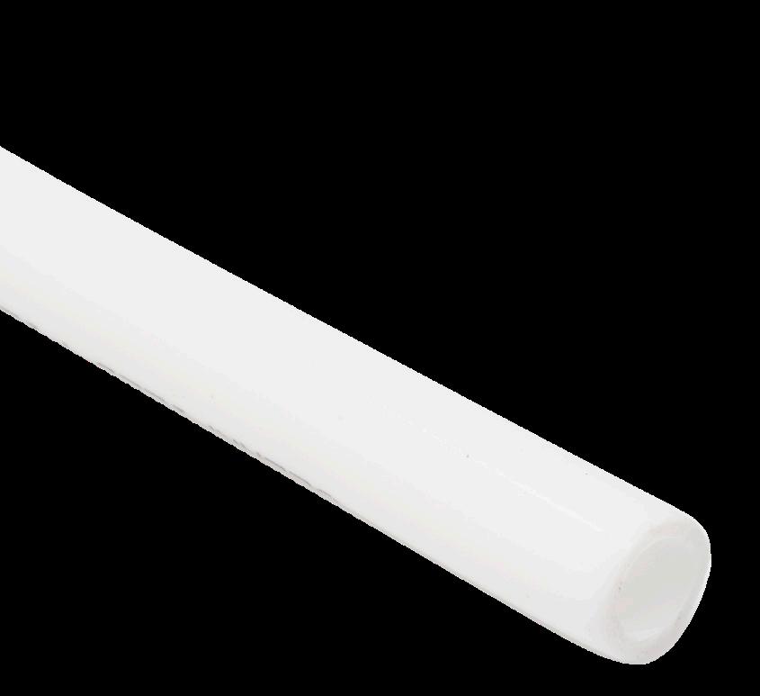
• High tension and crush resistance allows microduct to be pushed through existing conduit and around tight corners without degrading microduct
Access
• Quick and easy to install
• Small 10 mm footprint makes FieldShield ideal for all types of indoor implementations maximizing space in ladder racks, raised floors and air handling elevator shafts
• Smooth core enables fiber to be pushed or pulled with minimal resistance
• White color for easy identification
Investment
• Extends the capacity of existing conduit previously considered exhausted
FieldShield ®
Plenum 10/6 mm Microduct
Technical Specifications
FieldShield Plenum 10/6 mm Microducts
Length 2,000 feet (609.60 m) per spool (-0 / +5%)
Outside Diameter
0.394" (10.01 mm)
Inside Diameter 0.272" (6.91 mm)
Wall Thickness 0.059" (1.50 mm)
Slip Layer Minimum 0.004" (0.102 mm)
Ovality ≤ 5%
Minimum Bend-Radius 6" (152.40 mm) radius, supported 4” (101.60 mm), unsupported 8” (203.20 mm)
Material Polyvinylidene Difluoride (PVDF)
Rating Plenum rated
Operating Temperature -40°F to 176°F (-40°C to 80°C)
Installation Temperature -14°F to 158°F (-26°C to 70°C)
Color White
Tone Wire N/A
Tone Wire Diameter N/A
Markings Part number, lot number, footage markers every two feet (609.60 mm)
Spool Size 12" ID x 24" OD x 15" W (304.80 mm x 609.60 mm x 381.00 mm)
Weight 104 lbs (47 kg)
Pre-Configured Part Numbers
Part Number Description
FS-MCP-NT-610-2000F FieldShield Microduct, 10 mm, Indoor Plenum, non-toneable, white, 2000 feet (609.60 m)
FieldShield ®
Plenum 12.7/10 mm Microduct
Application
Plenum rated microducts provide a self extinguishing raceway to protect and deploy optical fiber in airspaces, raised floors and other indoor applications designated as plenum air spaces. Plenum 12.7/10 mm Microduct has an outer diameter of 12.7 mm and an inner diameter of 10 mm.
Description
FieldShield Plenum 12.7/10 mm Microduct is a durable, polyvinylidene difluoride (PVDF) crush resistant microduct suitable for protecting fiber in any indoor application. Easily mated with an airtight and waterproof coupler, FieldShield Plenum Microducts integrate with direct bury and aerial microducts creating a single and continuous pathway from outside plant to inside plant environments.
Features and Benefits
Integrity
• Compliant to Telcordia GR-3155
• Conforms to UL-2024. ETL listed.
Protection
• Plenum rated material self-extinguishes flame and does not reignite
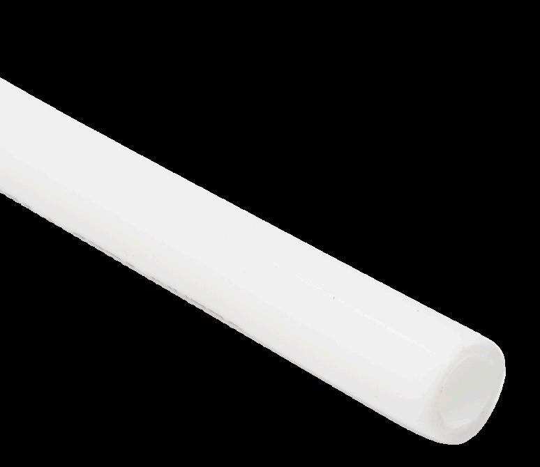
• High tension and crush resistance allows microduct to be pushed through existing conduit and around tight corners without degrading microduct
Access
• Quick and easy to install
• Small 10 mm footprint makes FieldShield ideal for all types of indoor implementations maximizing space in ladder racks, raised floors and air handling elevator shafts
• Straight ribs with silicone lining enables fiber to be pushed or pulled with minimal resistance
• White color for easy identification
Investment
• Extends the capacity of existing conduit previously considered exhausted
FieldShield ®
Plenum 12.7/10 mm Microduct
Technical Specifications
FieldShield Plenum 12.7/10 mm Microducts
Length 1,500 feet (457.20 m) per spool (-0 / +5%)
Outside Diameter 0.500" (12.70 mm)
Inside Diameter
0.408" (10.36 mm)
Wall Thickness 0.042" (1.07 mm)
Slip Layer Minimum 0.004" (0.102 mm)
Ovality ≤ 5%
Minimum Bend-Radius 8” (203.20 mm) radius
Material Polyvinylidene Difluoride (PVDF)
Rating Plenum rated
Operating Temperature -40°F to 176°F (-40°C to 80°C)
Installation Temperature -14°F to 158°F (-26°C to 70°C)
Color White
Tone Wire N/A
Tone Wire Diameter N/A
Markings Part number, date code, footage markers every two feet (609.60 mm)
Spool Size 12” ID x 24” OD x 20” W (304.80 mm x 609.60 mm x 508.00 mm)
Weight 125 lbs (57.00 kg)
Pre-Configured Part Numbers
Part Number Description
FS-DCP-NT-612.7-PS-1500F FieldShield Microduct, 12.7 mm, Indoor Plenum, non-toneable, white, 1500 feet (457.20 m)
FieldShield ®
Riser Rated 10/6 mm Microduct
Application
Simplifying the placement of fiber, while providing protection for all indoor elements, FieldShield Riser Rated 10/6 mm Microduct is specifically designed for applications requiring small pathways in confined spaces. Rugged crush resistance protects FieldShield Riser Rated 10/6 mm Microduct from the rigors of all industry standard deployment methods, while the rigid column strength allows microducts to be deployed through occupied duct previously thought to be exhausted. Riser Rated 10/6 mm Microduct has an outer diameter of 10 mm and an inner diameter of 6 mm.
Description
FieldShield Riser Rated 10/6 mm Microduct is a durable, crush resistant micro-conduit designed to increase the protection of fiber while decreasing installation and maintenance expenses. Manufactured using high density thermoplastic, FieldShield Riser Rated Microduct offers superior durability and protection.
Features and Benefits
Integrity
• Compliant to Telcordia GR-3155
• UL-2024 listed
Protection
• Quick and easy to install
• Riser Rated 10/6 mm Microduct has high tensile strength and crush resistance
• Designed for applications designated as riser air space Access
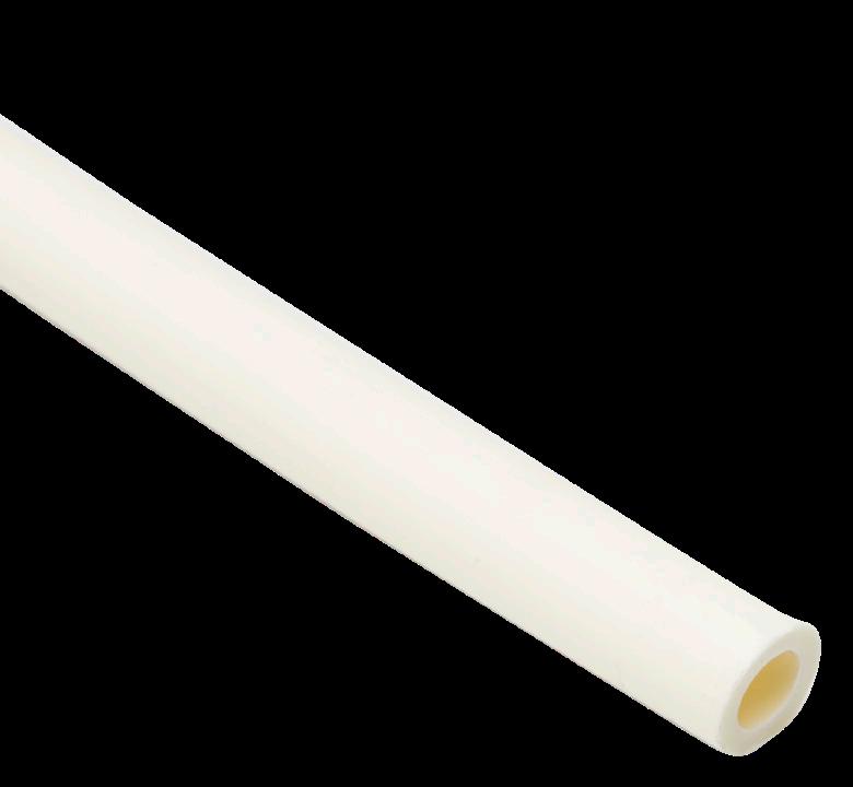
• Industry standard beige provides high visibility for indoor installation applications in existing conduit and by itself
• Standard nylon pull string simplifies deployment of fiber
• Smooth core slip lining reduces drag co-efficient enabling fiber to be pushed or pulled with minimal resistance Investment
• Maximizes capacity of existing conduit previously considered exhausted
• Provides industry leading protection for any indoor riser rated application
FieldShield ®
Riser Rated 10/6 mm Microduct
Technical Specifications
FieldShield
Pre-Configured Part Numbers
FieldShield ®
Riser Rated 14/10 mm Microduct
Application
Simplifying the placement of fiber, while providing protection for all indoor elements, FieldShield Riser Rated 14/10 mm Microduct is specifically designed for applications requiring small pathways in confined spaces. Rugged crush resistance protects FieldShield Riser Rated 14/10 mm Microduct from the rigors of all industry standard deployment methods, while the rigid column strength allows microducts to be deployed through occupied duct previously thought to be exhausted. Riser Rated 14/10 mm Microduct has an outer diameter of 14 mm and an inner diameter of 10 mm.
Description
FieldShield Riser Rated 14/10 mm Microduct is a durable, crush resistant micro-conduit designed to increase the protection of fiber while decreasing installation and maintenance expenses. Manufactured using high density thermoplastic, FieldShield Riser Rated Microduct offers superior durability and protection.
Features
and Benefits
Integrity
• Compliant to Telcordia GR-3155
• UL-2024 listed
Protection
• Quick and easy to install
• Riser Rated 14/10 mm Microduct has high tensile strength and crush resistance
• Designed for applications designated as riser air space Access

• Industry standard beige provides high visibility for indoor installation applications in existing conduit and by itself
• Standard nylon pull string simplifies deployment of fiber
• Smooth core slip lining reduces drag co-efficient enabling fiber to be pushed or pulled with minimal resistance Investment
• Maximizes capacity of existing conduit previously considered exhausted
• Provides industry leading protection for any indoor riser rated application
FieldShield ®
Riser Rated 14/10 mm Microduct
Technical Specifications
Pre-Configured Part Numbers
Microduct, 14 mm, riser, non-toneable, white, 1,500 foot (457.20 mm) spool
FieldShield ® Aerial 10/8 mm Microduct
Application
Designed to simplify the placement of fiber, FieldShield Aerial 10/8 mm Microduct is a durable 10/8 solution, protecting fiber from exposed outdoor environments. FieldShield Aerial Microduct easily integrates into pole mounted distribution terminals providing an aerial pole to pole distribution and “last mile” drop to the customer premise.
Description
FieldShield Aerial 10/8 mm Microduct is a 10 mm diameter, self-supporting (figure-8 style) microduct intended to deploy fiber the same way an aerial drop is installed. Designed to comply with North American storm and ice loading standards, the strength member makes FieldShield Aerial 10/8 mm Microduct the solution for spanning up to 500 feet (152.40 m).
The FieldShield Aerial 10/8 mm Microduct supports FieldShield Pushable Optical Fiber up to 3 mm in diameter.
Features and Benefits
Integrity
• Compliant to Telcordia GR-3155
Protection
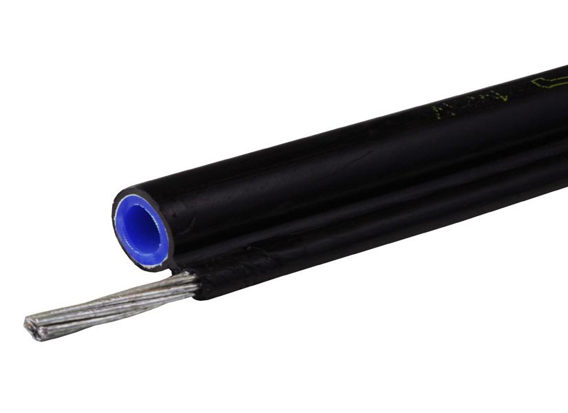
7 strands of 1.6 mm galvanized steel (twisted)
• High crush and tension resistance protects duct from harshest environmental conditions
• Made with MDPE to prevent degradation from sun and elements
Access
• Industry standard black for high visibility in aerial applications
• External aerial strength support requires Clearfield FS-DEADEND-AD10 for dead end application
• Quick and easy to install in self-supporting aerial applications
• Smooth core with additional slip lining enables fiber to be pushed or pulled with minimal resistance
• Standard nylon pull string simplifies deployment of fiber when pulling or using a push/pull combo
Investment
• Tech-friendly deployment methods reduce installation expenses
FieldShield ® Aerial 10/8
mm Microduct
Technical Specifications
FieldShield Aerial 10/8 mm Microduct
Outside Diameter
(9.8mm +/-0.2mm)
(8 mm)
mm) radius Maximum
Rating Length
foot (152.40 m) span in North America heavy zone
x 1.6 mm stranded galvanized Markings Part number, lot number, footage markers every foot
Pre-Configured Part Numbers
Large Aerial Microduct Attachment
Description
FieldShield Large Aerial Microduct Attachment provides the quickest and easiest way to attach FieldShield Large 14/10 and 10/8 Figure-8 Microducts. Simply strip away the jacket from the support strand on the microduct to accommodate the dead end and place the attachment over the strand.
Pre-Configured Part Numbers
Part Number Description FS-DEADEND-AD10 Microduct, Aerial 14/10 and 10/8 Dead End, Large Cable
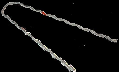
FieldShield ®
Aerial 14/10 mm Microduct
Application
Designed to simplify the placement of fiber, FieldShield Aerial 14/10 mm Microduct is a durable 14/10 solution, protecting fiber from exposed outdoor environments. FieldShield Aerial Microduct easily integrates into pole mounted distribution terminals providing an aerial pole to pole distribution and “last mile” drop to the customer premise.
Description
FieldShield Aerial 14/10 mm Microduct is a 14 mm diameter, self-supporting (figure-8 style) microduct intended to deploy fiber the same way an aerial drop is installed. Designed to comply with North American storm and ice loading standards, the strength member makes FieldShield Aerial 14/10 mm Microduct the solution for spanning up to 500 feet (152.40 m). The FieldShield Aerial 14/10 mm Microduct supports FieldShield Pushable Optical Fiber up to 5.5 mm in diameter.
Features and Benefits
Integrity
• Compliant to Telcordia GR-3155
Protection
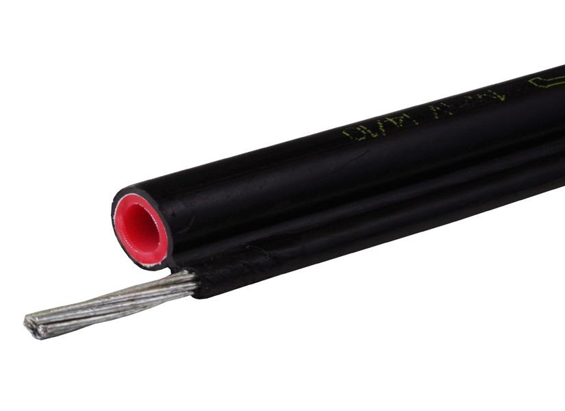
7 strands of 1.6 mm galvanized steel (twisted)
• High crush and tension resistance protects duct from harshest environmental conditions
• Made with HDPE to prevent degradation from sun and elements
Access
• Industry standard black for high visibility in aerial applications
• External aerial strength support requires Clearfield FS-DEADEND-AD10 for dead end application
• Quick and easy to install in self-supporting aerial applications
• Smooth core with additional slip lining enables fiber to be pushed or pulled with minimal resistance
• Standard nylon pull string simplifies deployment of fiber when pulling or using a push/pull combo
Investment
• Tech-friendly deployment methods reduce installation expenses
FieldShield ® Aerial 14/10
mm Microduct
Technical Specifications
FieldShield Aerial 14/10 mm Microduct Length 1,250 feet (381 m) per spool (-0 / +5%)
Outside Diameter
Inside Diameter
Wall Thickness
Slip
(14 mm +/- 0.2 mm)
(9.91 mm)
(2 mm +/- 0.2 mm)
0.004” (0.102 mm) Max.
Crush Resistance
Rating Length 500 foot (152.40 m) span in North America heavy zone
Minimum Bend-Radius 12” (304.80 mm) radius
Operating
Color Black
to
Figure 8 Strength Wire Material 7 x 1.6 mm stranded galvanized
Markings Part number, lot number, footage markers every foot
Spool Size 35” (889 .00 mm) No OD Reel Weight (3,281 feet on spool) 394 lbs. (178 kg)
Configured Part Numbers
Large Aerial Microduct Attachment
Description
FieldShield Large Aerial Microduct Attachment provides the quickest and easiest way to attach FieldShield Large 14/10 and 10/8 Figure-8 Microducts. Simply strip away the jacket from the support strand on the microduct to accommodate the dead end and place the attachment over the strand.
Pre-Configured Part Numbers
Part Number Description
FS-DEADEND-AD10 Microduct, Aerial 14/10 and 10/8 Dead End, Large Cable
FieldShield ®
Duct Accessories
Rotary Duct Cutter
Description
Rotary Duct Cutters are designed to make cutting all standard microducts as simple as possible without cutting the pull string inside.
Pre-Configured Part Numbers
Duct Cutter
Description
The Duct Cutter is used to make a clean, flat cut on any Clearfield ® microduct products. It resembles a cigar cutter in that it has a fixed blade that is attached to a hinged mechanism to “cleave” the duct. This provides a clean cut that is suitable for insertion into a coupler. Care should be taken when handling the cutter as the blade is very sharp.
Pre-Configured Part Numbers
Duct Cutter, 8 mm to 14 mm microducts
De-Burring Tool
Description
Microduct De-Burring Tools are designed to make chamfering the inside of microducts simple, helping to ensure pushing and pulling are smooth operations. It is used after a cut has been made to the microduct and prior to inserting a cut microduct into a coupler. The purpose of the de-burring tool is to form a conical shape on the inside surface of the microduct that, after insertion into a coupler, allows the fiber to glide between microducts with ease.
Pre-Configured Part Numbers
Part
FS-MD-DBR-TOOL FieldShield Microduct De-Burring Tool, 8 mm to 10 mm, blue
Microduct Proofing Mandrel
Description
The FieldShield Microduct Proofing Mandrels allow the installer to proof duct installation prior to push/ pull the drop.
Pre-Configured
Part Numbers
Part Number

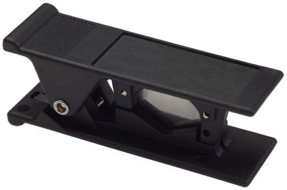

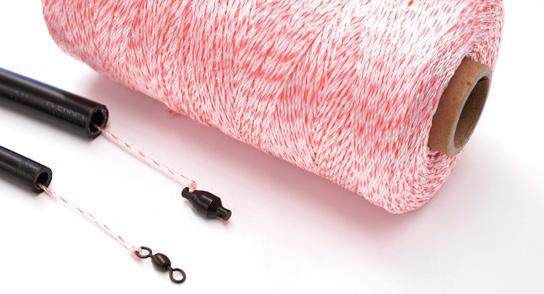
FS-DUCT-PROOFING-KIT Proofing Mandrel for 6 mm and 10 mm duct, which includes 2000F spool of pull string
FS-DUCT-PROOFINGTOOL Proofing Mandrel for 6 mm and 10 mm duct
FieldShield ®
Duct Accessories
Replacement Pull String
Description
The FieldShield Replacement Pull String allows the installer to replace string in microduct or blow sting into unoccupied duct.
Pre-Configured Part Numbers
Part Number Description
FS-PUL-STRING-2000F Replacement Pull String, 50 lb., 2000 Foot Spool
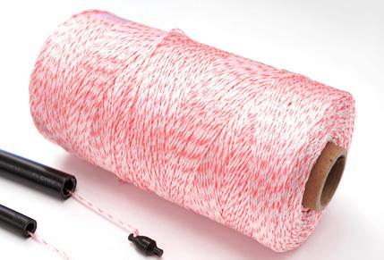
FS-PUL-YOURX Pulling Tool, YOURx Breakout, for 50 lb. Maximum Pulling Force, 10mm FlexPort
Airtight Coupler
Description
Airtight Couplers are designed to provide simple, 2-click plug-and-play joining of microducts, enabling longer runs and safe pushing and pulling performance.
Pre-Configured Part Numbers
Part
FS-CPLR-7MM-7MM-10
FS-CPLR-8MM-8MM-10
FS-CPLR-10MM-10MM-10
FS-CPLR-12.7MM-12.7MM-10
FS-CPLR-14MM-14MM-10
Description
FieldShield Microduct Airtight Coupler, 7 mm to 7 mm, 10 pack
FieldShield Microduct Airtight Coupler, 8 mm to 8 mm, 10 pack
FieldShield Microduct Airtight Coupler, 10 mm to 10 mm, 10 pack
FieldShield Microduct Airtight Coupler, 12.7 mm to 12.7 mm, 10 pack
FieldShield Microduct Airtight Coupler, 14 mm to 14 mm, 10 pack
Airtight Transition Coupler
Description
Airtight Transition Couplers are used to join two different sizes of microduct.
Pre-Configured Part Numbers
Part Number Description
FS-CPLR-8MM-10MM-10
FS-CPLR-10MM-12.7MM-10
FS-CPLR-12.7MM-14MM-10
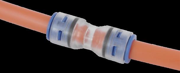
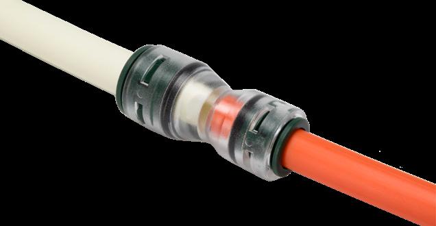
FieldShield Microduct Airtight Transition Coupler, 8 mm to 10 mm, 10 pack
FieldShield Microduct Airtight Transition Coupler, 10 mm to 12.7 mm, 10 pack
FieldShield Microduct Airtight Transition Coupler,12.7 mm to 14 mm, 10 pack
FieldShield ®
Duct Accessories
End Cap
Description
End caps are airtight caps used to keep debris out of the end of the microduct when pulling duct through existing conduit and plowed holes, sealing the end of the conduit temporarily. The end cap is a clear cap that installs much like the couplers providing an airtight seal.
Pre-Configured Part Numbers
Part Number
FS-END-STP-10MM-10
FS-END-STP-12.7MM-10
FS-END-STP-14MM-10
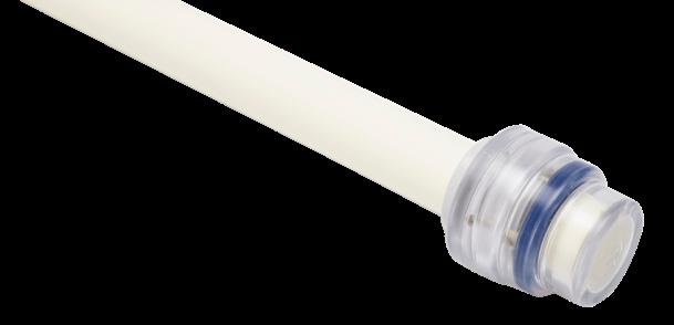
FieldShield Microduct End Caps, 10 mm, 10 pack
FieldShield Microduct End Caps, 12.7 mm, 10 pack
FieldShield Microduct End Caps, 14 mm, 10 pack
Microduct Field Repair Kit
Description
There are many situations where two microducts need to be coupled together to continue the conduit pathway. Regardless of whether the microduct was cut after initial installation or if the duct pathway simply needs to be continued, the FieldShield Microduct Repair Kit provides all the components to properly couple two microducts. For toneable duct, the kit includes components to ensure tone wire circuit integrity for ground locating.
Pre-Configured Part Numbers
Part
FS-MD-FLD-RPR-KIT-7MM
FS-MD-FLD-RPR-KIT
FS-MD-FLD-RPR-KIT-14MM
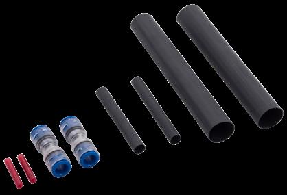
FieldShield Microduct Field Repair Kit, 7 mm
FieldShield Microduct Field Repair Kit, 10 mm
FieldShield Microduct Field Repair Kit, 14 mm
Microduct Pulling Carrots
Description
The FieldShield Microduct Pulling Carrot screws into the inner bore of the duct and provides an attachment point to direct bury FieldShield Microducts to pull them through existing conduit systems.
Pre-Configured Part Numbers
Part
FS-PUL-CRT-6MM-M FieldShield Microduct Pulling Carrot, 6 mm ID, metal, with string tie on
FS-PUL-CRT-10MM-M
FieldShield Microduct Pulling Carrot, 10 mm ID, metal, with string tie on
FieldShield ®
Duct Accessories
Aerial Microduct Attachment
Description
The Aerial Microduct Attachments provide a quick and easy way to attach FieldShield Aerial figure-8 style microducts. Strip away the jacket from the support strand on the microduct to accommodate the dead end or aerial splice and wrap the attachment onto the strand for a secure and permanent installation.
Pre-Configured Part Numbers
Part Number
FS-DEADEND
FS-DEADEND-AD10
FS-AERIAL-SPLICE
Description
FieldShield Aerial Microduct Attachment, dead end
FieldShield Aerial Microduct Attachment, large cable
FieldShield Aerial Microduct Attachment, open wire splice, galvanized, BWG-10 0.134” x 14” (3.40 mm x 355.60 mm)
Introduction to Fiber Cable Assemblies
FiberDeep ® and Cable Assemblies
Combining 40+ years of experience from its founding members, Clearfield ® designs and manufactures fiber optic cable assemblies for virtually any application. Our connectivity expertise, coupled with a personalized approach, gives our customers a level of service and quality that out performs all other manufactures.
FiberDeep ®, a guaranteed 0.2 dB loss, half that of the industry standard, is available on every singlemode simplex and duplex fiber optic patch cord and ribbon fan-outs deployed within the Clearview ® Cassette. Our FiberDeep cable assemblies improve your fiber network’s performance while reducing the cost of deployment. No matter what kind of traffic your network carries, the success of your business comes down to the quality of your cable plant.
Simply the best patch cords around, Clearfield offers cable assemblies in custom and standard lengths, ranging from simple multimode and singlemode patch cords, to some of the most complex assemblies for inside and outside plant environments, including distribution cable, OSP breakout-style, drop cable and drop node assemblies. Automated polishing processes ensure precise control of polish radius, apex offset and fiber undercut. Our process engineers have perfected termination techniques for all types of specialty cable designs, including ribbon fiber, high-fiber counts and ruggedized cables. We support all industry standard connector types, including the industry’s latest hardened fiber optic connectors (HFOC).
Clearfield cable assemblies are used in the most demanding environments, from global manufacturing to emerging communications. Clearfield fiber optic cable assemblies exceed industry standards for insertion loss and return loss performance. Our controlled design processes pay strict attention to cable prep, termination and epoxy curing along with tight end-face geometries. Our cleanliness is second to none. We can design and manufacture fiber optic cable assemblies for almost any application, meeting your requirements for cost, performance, reliability and rapid delivery.


Fiber Cable Assemblies
Indoor Fiber Jumper Cables
Application
A fiber jumper, sometimes called a fiber patch cord, is a length of fiber cabling fitted with connectors at each end. They are used to connect end devices or network hardware.
Description
Clearfield ® offers singlemode and multimode, simplex and duplex Indoor Fiber Jumper Cables manufactured to tight internal specifications that exceed industry-accepted standards. Fiber assemblies are used in a variety of carrier networks and private network environments. The key to manufacturing high-performance fiber assemblies is controlling polish radius, apex offset and fiber undercut. Clearfield monitors its automated polishing process to exceed industry specifications for insertion and return loss, ensuring a top-quality product.
Features and Benefits
Integrity
• Terminations are designed and tested to Telcordia GR-326

• Clearfield ® FiberDeep ® Guarantee: 0.2 dB insertion loss or less, exceeding industry standards
• Supports industry standard singlemode and multimode connectors
• Singlemode and multimode and hybrid cables available
Protection
• Each fiber is individually covered with an outer jacket for added protection
• Wide variety of jacket sizes for all applications, 3 mm, 2 mm, 1.6 mm, 1.2 mm, 900 μm
• Riser and Plenum rated jacket options available
• Available in simplex, dual-round and dual zip-cord configurations
Access
• Compact jacket design minimizes cable pile up
• Industry standard terminations include SC and LC (ask a Clearfield representative for other connector availability)
Investment
• Indoor Jumper Assemblies offer an economical solution for deploying fiber in any optical network
• Environmentally stable, low-insertion loss, minimal back reflection
• All assemblies are 100% tested
Technical Specifications
Indoor Fiber Jumper Cables
Core Size and Type
Fiber Count
Jacket O.D.
Cable Types
Singlemode and multimode
Simplex (1-fiber) and duplex (2-fiber)
900 μm, 1.6 mm, 2.0 mm, 3.0 mm
Indoor Riser, Indoor Plenum
Connector Types SC/UPC, SC/APC, LC/UPC, LC/APC
Operating Temperature -40°C to 85°C (-40°F to 185°F)


Fiber Cable Assemblies
Indoor Fiber Jumper Cables
Minimum Performance Specifications for Terminated Singlemode Connectors
Minimum Performance Specifications for Terminated Multimode Connectors
Configured Part Numbers
Disclaimer/Note: Paper configurator shown is for reference only and should not be used to configure a saleable product configuration. All options shown on paper configurators may not be available or compatible with other options listed. Please contact your Clearfield representative for assistance in product configurations.
Connector # 2
= Indoor, riser rated
= Indoor, plenum
Select Mode / Type
1 = Singlemode
3 = Multimode (62.5)
5 = Multimode (50) – non-ribbon
7 = Multimode (50) laser opt– non-ribbon OM
9 = Multimode (50) OM4
3 Select Fiber Count
001 = Simplex 002 = Duplex Select Connector # 1
Boot
= SC/APC G = LC/APC
= SC/APC DX Z = Pigtail E = LC /UPC
Select Boot
or XXXF
= Length in meters
= Length in feet
Indoor Bend-Insensitive Fiber Jumper Cables Fiber Cable Assemblies
Application
A fiber jumper, sometimes called a fiber patch cord, is a length of fiber cabling fitted with connectors at each end. They are used to connect end devices or network hardware.
Description
Indoor Bend-Insensitive Fiber Jumper Cables are used in a variety of carrier networks and private network environments. The key to manufacturing high-performance fiber assemblies is controlling polish radius, apex offset and fiber undercut. Clearfield ® monitors its automated polishing process to exceed industry specifications for insertion and return loss, ensuring a top-quality product.
Features and Benefits
Integrity
• Terminations are designed and tested to Telcordia GR-326
• Clearfield ® FiberDeep ® Guarantee: 0.2 dB insertion loss or less, exceeding industry standards
• Supports industry standard singlemode connectors
• Singlemode G.657.A1 and A2 bend-insensitive glass fiber Protection
• Riser and Plenum rated bend-insensitive jacket options available
• Available in simplex, dual-round and dual zip-cord configurations
Access
• Compact jacket design minimizes cable pile up
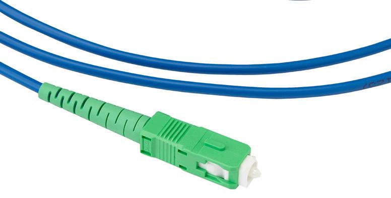
• Industry standard terminations include SC and LC (ask a Clearfield representative for other connector availability) Investment
• Indoor Bend-Insensitive Fiber Jumper Cables offer an economical solution for deploying fiber in any optical network
• Environmentally stable, low-insertion loss, minimal back reflection
• All assemblies are 100% tested
Indoor Bend-Insensitive Fiber Jumper Cables Fiber Cable Assemblies
Technical Specifications
Indoor Bend-Insensitive Fiber Jumper Cables
Core Size and Type
Singlemode (G.657.A1 and G.657.A2)
Fiber Count Simplex (1-fiber) and duplex (2-fiber)
Jacket O.D. 2.0 mm
Cable Types Indoor Riser
Connector Types
SC/UPC, SC/APC, LC/UPC, LC/APC
Operating Temperature -40°C to 85°C (-40°F to 185°F)
Minimum Performance Specifications for Terminated Singlemode Connectors
Configured Part Numbers
Disclaimer/Note: Paper configurator shown is for reference only and should not be used to configure a saleable product configuration. All options shown on paper configurators may not be available or compatible with other options listed. Please contact your Clearfield representative for assistance in product configurations.
Indoor Traceable Fiber Jumper Cables Fiber Cable Assemblies
Application
The Indoor Traceable Fiber Jumper Cable is an effective solution for eliminating interconnect errors in dense interconnect environments. The traceable light identification will eliminate accidentally unplugging or moving the wrong jumper. Whether it is coming from the back of the equipment rack to the front or from one cross-connect panel to another, the Traceable Jumper Cable uses a positive light indication to quickly identify the opposite end of the assembly. The added value of eliminating the outages, due to incorrectly identifying jumpers and the time saved being able to quickly find the correct jumper, is important in today’s demanding market.
Description
The traceability of the jumper gives a value-add functionality for simple fiber patch cord jumpers. Having the ability to trace the other end of the assembly with an easy to find highly visible red LED eliminates the chance of accidentally unplugging or moving the wrong jumper. This is a must in high density environments like central offices, CATV head ends, and cellular sites, anywhere cable congestion can create a challenge when identifying and tracing patch cords.
Features and Benefits
Integrity
• Terminations are designed to Telcordia GR-326
• Insertion loss and back reflection meets or exceeds industry standards
• Supports industry standard Singlemode and Multimode connectors
• Available for Singlemode and Multimode Simplex and Duplex Cables Protection
• Each fiber is individually covered with an outer jacket for added protection
• Wide variety of jacket sizes for all applications: 2 mm
• Riser and plenum rated jacket options available
• Individually packaged and labeled Access
• Compact jacket design minimizes cable pile up
• Industry standard terminations include SC and LC
• High intensity red LED light source used for identification Investment
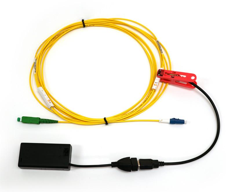
• Offers a sound solution for reducing unexpected outages due to human error and reduces labor costs by quickly identifying the correct assembly right away the first time
• Environmentally stable, low-insertion loss, minimal back reflection
• All assemblies are tested 100%
Fiber Cable Assemblies
Indoor Traceable Fiber Jumper Cables
Technical Specifications
Indoor Traceable Fiber Jumper Cables
Core Size Singlemode, Multimode
Fiber Count Simplex (1-fiber) and Duplex (2-fiber)
Jacket Outer Diameter 2.0 mm
Cable Types Indoor Riser, Indoor Plenum
Connector Types SC/UPC, SC/APC, LC/UPC, LC/APC
Operating Temperature -20°C to 70°C (-4°F to 158°F)
Minimum Performance Specifications for Terminated Singlemode Traceable Connectors
Minimum Performance Specifications for Terminated Multimode Traceable Connectors
Configured Part Numbers
Disclaimer/Note: Paper configurator shown is for reference only and should not be used to configure a saleable product configuration. All options shown on paper configurators may not be available or compatible with other options listed. Please contact your Clearfield representative for assistance in product configurations.
Select Mode and Type
1
3 =
5
7 = 50 µm LO OM3
9 = 50 µm OM4
Select Fiber Count
001 = Simplex
002 = Duplex
Select Connector #1
A = SC/UPC E = LC/UPC
B = SC/UPC DX F = LC/UPC DX
C = SC/APC G = LC/APC
D = SC/APC DX H = LC/APC DX
4 Select Connector #2
A = SC/UPC E = LC/UPC
B = SC/UPC DX F = LC/UPC DX
C = SC/APC G = LC/APC
D = SC/APC DX H = LC/APC DX
XXXM = Length in meters
XXXF = Length in feet XXXI = Length in inches XXXM, XXXF or XXXI
A TRACE-LITE-02 power source is required to power the LED traceable lights. Power source can be used for all Traceable jumpers. Power source is sold separately.
Pre-Configured Part Numbers
Part Number Description
TRACE-LITE-02 Power lite source with extension cord for traceable fiber patchcords
Fiber Cable Assemblies
Outdoor Ruggedized Fiber Jumper Cables
Application
These jumpers are ideal when splicing FTTH drops in the ONT/NID. Indoor cordage stiffens and retains cable memory in cold weather. These jumpers remain flexible even in extreme conditions. These assemblies use bend-insensitive fiber to help eliminate bend-radius issues inside the NID. These patch cords also work well in outside plant cross-connect cabinets.
Description
Clearfield ® Outdoor Ruggedized Fiber Jumper Cables can be ordered in any industry standard connector type. Any length in feet or meters is available.
Features and Benefits
Integrity
• Terminations are designed and tested to Telcordia GR-326
• Clearfield ® FiberDeep ® Guarantee: 0.2 dB insertion loss or less, exceeding industry standards
• Supports industry standard singlemode connectors
• Singlemode bend-insensitive ITU standard G.657.A glass fiber
Protection
• Uses Ruggedized OSP rated 2 mm black jacketed cable
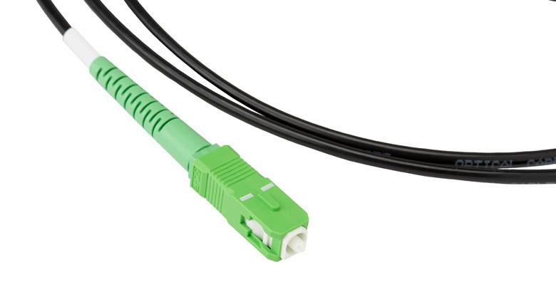
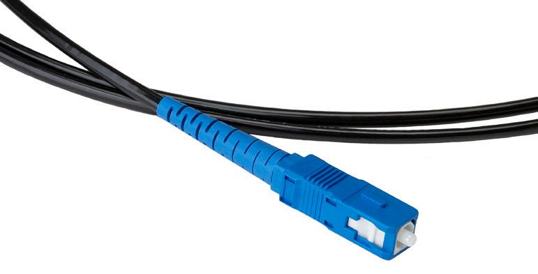
• Patch cords remain flexible and durable in extreme temperatures of -55°C to 85°C (-67°F to 185°F)
Access
• Compact jacket design minimizes cable pile up
• Industry standard terminations include SC and LC (ask a Clearfield representative for other available connectors)
Investment
• Outdoor Ruggedized Fiber Jumper Cables offer an economical solution for deploying fiber in any OSP optical network
• Environmentally stable, low-insertion loss, minimal back reflection
• All assemblies are 100% tested
Recommendation
Clearfield recommends the use of Ruggedized Outside Plant Jumpers when splicing in the NID or ONT. We also suggest two meter jumpers for use in FieldSmart ® cabinet applications. Clearfield stocks common length SC/APC Ruggedized Jumpers for customer convenience. For non-standard lengths, lead times will apply.
Fiber Cable Assemblies
Outdoor Ruggedized Fiber Jumper Cables
Technical Specifications
Outdoor Ruggedized Fiber Jumper Cables
Core Size and Type
Singlemode (G.657.A1)
Fiber Count Simplex (1-fiber)
Jacket O.D. 2.0 mm
Cable Types Outdoor - Ruggedized Polyurethane
Connector Types
SC/UPC, SC/APC, LC/UPC, LC/APC
Operating Temperature -40°C to 85°C (-40°F to 185°F)
Minimum Performance Specifications for Terminated Singlemode Connectors
Configured Part Numbers
Disclaimer/Note: Paper configurator shown is for reference only and should not be used to configure a saleable product configuration. All options shown on paper configurators may not be available or compatible with other options listed. Please contact your Clearfield representative for assistance in product configurations.
Select Connector # 1
A = SC/UPCJ = FC/UPC
C = SC/APCK = FC/APC
E = LC/UPCM = ST/UPC
G = LC/APC
Select Jacket Size *
B = 2 mm
Select Connector # 2
A = SC/UPCJ = FC/UPC
C = SC/APCK = FC/APC
E = LC/UPCM = ST/UPC
G = LC/APCZ = Pigtail
Select Jacket Size * B = 2 mm
= Pigtail

Indoor-Outdoor Bend-Insensitive Fiber Jumper Cables Fiber Cable Assemblies
Application
A fiber jumper, sometimes called a fiber patch cord, is a length of fiber cabling fitted with connectors at each end. They are used to connect end devices or network hardware.
Description
Indoor-Outdoor Bend-Insensitive Fiber Jumper Cables are used in a variety of carrier networks and private network environments. The key to manufacturing high-performance fiber assemblies is using high quality connector components and controlling the termination and polishing process. Clearfield ® monitors its automated polishing process to exceed industry specifications for insertion and return loss, ensuring a top-quality product.
Features
and Benefits
Integrity
• Terminations are designed and tested to Telcordia GR-326
• Clearfield® FiberDeep® Guarantee: 0.2 dB insertion loss or less, exceeding industry standards
• Supports industry standard singlemode connectors
• Singlemode G.657.B3 bend-insensitive glass fiber
Protection
• Indoor-Outdoor rated bend-insensitive jacket options available
• Available in simplex 3mm and 4.8mm jacket
Access
• Compact jacket design minimizes cable pile up
• Industry standard terminations include SC and LC for 3mm and SC only for 4.8mm
Investment
• Indoor Bend-Insensitive Fiber Jumper Cables offer an economical solution for deploying fiber in any optical network
• Environmentally stable, low-insertion loss, minimal back reflection
• All assemblies are 100% tested


Fiber Cable Assemblies
Indoor-Outdoor Bend-Insensitive Fiber Jumper Cables
Technical Specifications
Indoor-Outdoor Bend-Insensitive Fiber Jumper Cables
Core Size and Type
Fiber Count
Singlemode G.657.B
Simplex Fiber Only
Jacket O.D. 3mm, 4.8mm
Cable Types
Connector Types
Indoor/Outdoor Riser
3mm = SC/UPC, SC/APC, LC/UPC, LC/APC; 4.8mm = SC/UPC, SC/APC
Operating Temperature -40°C to 85°C (-40°F to 185°F)
Minimum Performance Specifications for Terminated Singlemode Connectors
Configured Part Numbers
Disclaimer/Note: Paper configurator shown is for reference only and should not be used to configure a saleable product configuration. All options shown on paper configurators may not be available or compatible with other options listed. Please contact your Clearfield representative for assistance in product configurations.
K = Indoor/Outdoor G657.B3 Black
KW = Indoor/Outdoor G657.B3 White
1 2 Select Cable Construction
A = SC/UPC
C = SC/APC
E = LC/UPC
G = LC/APC Select Connector #1
Select Jacket Size #1
Select Jacket Size #2 D = 3mm P = 4.8mm
Connector #2
A = SC/UPC
C = SC/APC
E = LC/UPC
G = LC/APC
Z = Pigtail
= 3mm
= 4.8mm
XXXM = Length in meters XXXF = Length in feet XXXM or XXXF
Fiber Cable Assemblies
MPO Assemblies
Application
MPO Assemblies are multi-fiber cables terminated into multi-fiber connectors. These cables can be used in indoor or outdoor applications. MPO terminations offer great plug-and-play solutions. Using MPO multi-fiber assemblies can eliminate termination and splicing in the field, which in turn reduces the expense of deployment. MPO assemblies offer a very high density solution that reduces your network’s overall footprint, which is especially beneficial in central office, headend and data center locations.
Description
Clearfield ® offers singlemode and multimode MPO fiber assemblies that are manufactured to tight specifications that exceed industry standards. MPO Assemblies are used in a variety of carrier networks, private networks and data center environments. Clearfield’s manufacturing process and quality control ensures a top-quality product for insertion loss and return loss.
Features and Benefits
Integrity

• Terminations are designed and tested to meet TIA/EIA and IEC intermateability standards
• MPO cable assemblies designed, tested and certified to GR-1435
• Supports Singlemode and Multimode cables and connectors
• 4, 8, 12 and 24 fiber terminations available (custom configurations available)
• Assemblies terminated MPO to MPO, MPO to non-terminated stub and MPO to multi-fiber breakout terminated with industry standard SC and LC
• RoHS compliant Protection
• Using outdoor and indoor plenum and riser rated fiber cables MPO assemblies can be installed just about anywhere
• MPO connectors can be terminated directly to bare fiber ribbon, loose-tube and up-jacketed cable
• Pulling-eye kits available to protect the terminated ends and will reduce deployment time and cost Access
• Compact multi-fiber connectors reduce cabinet and panel size
• Factory terminated MPO assemblies eliminate the need for termination and splicing in the field
• Custom fiber pin-out configurations available upon request Investment
• MPO Assemblies offer an economical solution for deploying fiber in any optical network
• Environmentally stable, low-insertion loss, minimal back reflection
• All assemblies are 100% tested
Fiber Cable Assemblies
MPO Assemblies
Technical Specifications
MPO Assemblies
Core Size and Type
Singlemode and multimode
Fiber Count 4, 6, 8, 12 and 24-fiber MPO terminations on multi-fiber cables
Jacket O.D.
Cable Types
Connector Types
Bare ribbon, flat and round jacketed ribbon or loose tube
Indoor (Riser/Plenum), Outdoor (Riser/Non-Rated)
SC/UPC, SC/APC, LC/UPC, LC/APC, MPO (male and female)
Operating Temperature -40°C to 85°C (-40°F to 185°F)
Breakout Length
Half meter, one meter, pulling eye, custom
Minimum Performance Specifications for Terminated MPO Connectors
Configured Part Numbers
Disclaimer/Note: Paper configurator shown is for reference only and should not be used to configure a saleable product configuration. All options shown on paper configurators may not be available or compatible with other options listed. Please contact your Clearfield representative for assistance in product configurations.
7 Select Breakout #2
Upjacketing
bend insensitive
= Multimode (62.5 μm) 5 = Multimode (50 μm) 7 = Multimode (50 μm) laser opt.
= Multimode (50 μm) OM4
Fiber Cable Assemblies
Outside Plant Fiber Assemblies
Application
Clearfield ® Outside Plant Fiber Assemblies are used in a variety of applications including DLC cabinets, PON cabinets, cross-connect cabinets and fiber termination panels. Standard OSP cable is used and the terminated end of the assembly is up-jacketed with either 900 μm or 2 mm tubing. The assembly is then terminated with the required connectors. Fiber counts can be from 2 to 288 fibers.
Description
Clearfield OSP Fiber Assemblies are designed to perform flawlessly in even the most harsh environments. Our process and design directly addresses failure prone areas such as the transition (where the fiber is broken out into individual units) and at the termination. We use a patented process in the fiber transition that not only protects the fiber but also ensures that no lateral movement occurs due to temperature variations. Standard breakouts are half meter and one meter. Clearfield can also do custom breakouts to meet your unique panel needs.
Features and Benefits
Integrity

• Cable and terminations are designed, tested and certified to GR-20, GR-326 and GR-1435
• Specialty cable designs available including ribbon fiber, loose-tube and ADSS (All-Dielectric Self-Supporting)
• Supports industry standard singlemode and multimode fiber Protection
• Rugged cable design protects against harsh outdoor environment
• Wide variety of up-jacket sizes for all applications, ruggedized 3 mm, 2 mm, 1.6 mm and 900 μm
• Loose tube available in a gel-filled design for full water-block or gel-free
• All dielectric design (except armored cable)
• Pulling-eye available to ease installation and for added protection Access
• Industry standard terminations include SC and LC (ask a Clearfield representative for other connector availability)
• Versatile cable designs well suited for in-conduit, lashed aerial and direct buried applications
• Fiber counts from two to 288 in loose tube or ribbon cables (higher fiber counts available) Investment
• Outside Plant Fiber Assemblies offer a rugged solution for deploying fiber in any OSP optical network
• Environmentally stable, low-insertion loss, minimal back reflection
• All assemblies are 100% tested
Recommendation
When designing a patch cord (double-ended assembly) that will be pulled through conduit a pulling eye may be a good solution. Any assembly with 24 fibers or less can be fitted with a pulling eye.
Technical Specifications
Outside Plant Fiber Assemblies
Core Size and Type Singlemode and multimode
Fiber Count 2-fiber to 288-fiber
Jacket O.D. 900 μm, 2.0 mm (48-fiber max), 3mm (for MPO terminations only)
Cable Types Outdoor (Riser/Non-Rated), Outdoor Armored (Riser/Non-Rated)
Connector Types SC/UPC, SC/APC, LC/UPC, LC/APC, MPO
Operating Temperature -40°C to 85°C (-40°F to 185°F)
Breakout Length Half meter, one meter, pulling eye, custom
Fiber Cable Assemblies
Outside Plant Fiber Assemblies
Minimum Performance Specifications for Terminated Singlemode Connectors Connector
Minimum Performance Specifications for Terminated Multimode Connectors
Configured Part Numbers
Disclaimer/Note: Paper configurator shown is for reference only and should not be used to configure a saleable product configuration. All options shown on paper configurators may not be available or compatible with other options listed. Please contact your Clearfield representative for assistance in product configurations.
1 2
Select Cable Construction
B = OSP, riser rated E = OSP, non-rated M = OSP, armored, non-rated
Select Mode / Type
1 = Singlemode, loose tube
2 = Singlemode, ribbon
3 = Multimode (62.5) loose tube
4 = Multimode (62.5) ribbon
5 = Multimode (50 µm) loose tube
6 = Multimode (50 µm) ribbon
7 = Multimode (50 µm LO) loose tube
8 = Multimode (50 µm LO) ribbon
3 Select Fiber Count *
X X X = port count in increments of 12
Select Connector # 1 4 Select Connector # 2
A = SC/UPC P = Pulling Eye
C = SC/APC Z = Pigtail
E = LC/UPC 5 = MPO male
G = LC/APC 6 = MPO female
Select Breakout # 1
Select Upjacketing # 1
Select Breakout # 2
B = 1 meter
C = 0.5 meter
Z = Pigtail
Select Upjacketing # 2
A = 900 µm
B = 2 mm (only up to 48 fiber)
Z = Pigtail
or XXXF
XXXM = Length in meters XXXF = Length in feet
Fiber Cable Assemblies
Distribution Assemblies
Application
Distribution assemblies are used for applications inside buildings and central offices. These cables utilize a 900 μm tight buffer jacket and are available in plenum and riser versions.
Description
Clearfield ® Distribution Assemblies are used where multi-fiber tight buffered constructions are required for density. These assemblies combine the bandwidth capacity of individual cable assemblies in one easy-to-use assembly, and can be used in OSP patch and splice (Clearfield’s in-cassette splicing solution) applications.
Features and Benefits
Integrity
• Terminations are designed and tested to Telcordia GR-326
• Supports Industry standard singlemode and multimode connectors
• Singlemode and multimode and hybrid cables available Protection
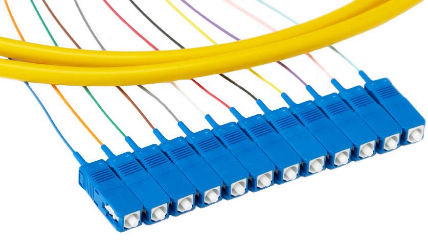
• Each fiber is individually jacketed then covered with an outer jacket for added protection
• All fibers are color coded using industry fiber color code
• Pulling-eye kits available to speed installation Access
• Compact jacket design keeps cable pile up minimal
• Industry standard terminations include SC and LC (Ask a Clearfield representative for other connector availability) Investment
• Distribution Assemblies offer an economical solution for deploying fiber in any optical network
• Environmentally stable, low-insertion loss, minimal back reflection
• All assemblies are 100% tested
Technical Specifications
Distribution Assemblies
Core Size and Type
Singlemode and multimode
Fiber Count 2-fiber to 144-fiber
Jacket O.D. 900 μm
Cable Types
Connector Types
Indoor Riser, Indoor Plenum
SC/UPC, SC/APC, LC/UPC, LC/APC, MPO
Operating Temperature -40°C to 85°C (-40°F to 185°F)
Breakout Length
Half meter, one meter, pulling eye, custom
Fiber Cable Assemblies
Distribution Assemblies
Minimum Performance Specifications for Terminated Singlemode Connectors Connector
Minimum Performance Specifications for Terminated Multimode Connectors
Configured Part Numbers
Disclaimer/Note: Paper configurator shown is for reference only and should not be used to configure a saleable product configuration. All options shown on paper configurators may not be available or compatible with other options listed. Please contact your Clearfield representative for assistance in product configurations.
Select Cable Constuction
= Indoor, riser rated C = Indoor, plenum rated
1 = Singlemode, tight buffer
2 = Singlemode, ribbon
Breakout # 2
A = SC/UPC Z = None
C = SC/APC 5 = MPO male
E = LC/UPC 6 = MPO female
G = LC/APC
Breakout #1
3 = Multimode (62.5), tight buffer
5 = Multimode (50), tight buffer
7 = Multimode (50) laser opt – tight buffer OM3
Select Mode/Type 3 Select Fiber Count
Select Connector #2
A = SC/UPC Z = None
C = SC/APC 5 = MPO male
E = LC/UPC 6 = MPO female
G = LC/APC
Fiber Cable Assemblies
Breakout Assemblies
Application
Breakout Assemblies are appropriate for low to mid-fiber count applications in demanding indoor and outdoor environments. Common uses include manufacturing areas, unprotected communication closets and small central offices.
Description
Breakout style assemblies are easy to install and simple to terminate without the need for fan-out kits. The indoor/outdoor version of this cable is durable and OFNR rated. While it can be used indoors, it also has a -40°C to 85°C operating temperature range and the benefits of fungus, water and UV protection making it perfect for outdoor applications. The indoor/outdoor versions come standard with 2.5 mm sub units. The indoor only cable is standard with 2 mm sub units.
Features and Benefits
Integrity
• Terminations are designed and tested to Telcordia GR-326
• Specialty rugged cable designs
• Supports industry standard singlemode and multimode fiber Protection
• Rugged cable design protects against harsh indoor and outdoor environments
• Wide variety of jacket sizes for all applications, ruggedized 3 mm, 2.5 mm and 2 mm
• Riser and Plenum and fire retardant rated cable jackets available
• Pulling-eye available to ease installation and for added protection Access
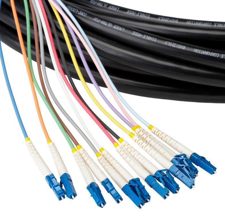
• Industry standard terminations include SC and LC (Ask a Clearfield ® representative for other available connectors)
• Versatile cable designs well suited for in-conduit, lashed aerial and direct buried applications
• Fiber counts from 2 to 48 Investment
• Breakout Fiber Assemblies offer a rugged solution for deploying fiber in any indoor/outdoor optical network
• Environmentally stable, low-insertion loss, minimal back reflection
• All assemblies are 100% tested
Recommendation
Consider using indoor/outdoor versions for use in DLC cabinets or outside plant electronic cabinets as a “tip” cable. The blunt end will be spliced in a splice vault and the other end will be plugged into the electronics inside the cabinet.
The 2 mm indoor version is ideal for use in cross-connect solutions. One end is loaded into the rear of a patch panel and the other end can be staggered to match any active gear blade.
Technical Specifications
Breakout Assemblies
Core Size and Type
Fiber Count
Jacket O.D.
Singlemode and multimode
2-fiber to 48-fiber
2.0 mm (indoor), 2.5 mm (indoor/outdoor)
Cable Types Indoor Riser, Indoor/Outdoor (Riser)
Connector Types
Operating Temperature
Breakout Length
SC/UPC, SC/APC, LC/UPC, LC/APC
-40°C to 85°C (-40°F to 185°F)
Half meter, one meter, pulling eye, custom
Fiber Cable Assemblies
Breakout Assemblies
Minimum Performance Specifications for Terminated Singlemode Connectors Connector
Minimum Performance Specifications for Terminated Multimode Connectors
Configured Part Numbers
Disclaimer/Note: Paper configurator shown is for reference only and should not be used to configure a saleable product configuration. All options shown on paper configurators may not be available or compatible with other options listed. Please contact your Clearfield representative for assistance in product configurations.
C = SC/APC
E = LC/UPC
G = LC/APC
= Pigtail Select Breakout # 2 Select Upjacketing # 2
B = 1 meter
C = 0.5 meter
P = Pulling eye
B = 2 mm
C = 2.5 mm Z = Pigtail
or XXXF
Z = Pigtail XXXM = Length in meters
= Length in feet
Drop Node Assemblies Fiber Cable Assemblies
Application
Drop Node Assemblies are designed to connect the optical distribution node to the optical drop cable in a CATV network.
Description
Clearfield ® ensures the quality of its Drop Node Assemblies by utilizing factory terminated connectors, a fully water-blocked entry connector, loose tube, gel-filled cable (on most assemblies) and a GR-326 compliant 900 μm fiber termination process. This provides exceptional performance and stability over a full range of outdoor temperatures and environmental conditions. The end-user gains complete control over drop access and reconfiguration.
Features and Benefits
Integrity
• Terminations are designed and tested to Telcordia GR-326
• Drop Node Assemblies make ease of installation into Optical Distribution Node (ODN)
• Supports industry standard singlemode fiber Protection
• Rugged cable design protects against harsh outdoor environments
• Fibers up-jacketed using materials which can endure temperatures from -40°C to 200°C
• Cables using loose tube gel-filled OSP cable are sealed to eliminate water penetration

• Feed Through Fitting (FTF) strain relief guarantees that movement does not occur at the transition into the ODN
• Strain relief matches cable load rating Access
• Industry standard terminations include SC and LC (ask a Clearfield representative for other available connectors)
• Provides maximum cable management inside ODN using 900 μm or 2 mm up-jacket
Investment
• Drop Node Assemblies offer a rugged solution for deploying fiber in any outdoor optical network
• Environmentally stable, low-insertion loss, minimal back reflection
• All assemblies are 100% tested
Fiber Cable Assemblies
Drop Node Assemblies
Technical Specifications
Drop Node Assemblies
Core Size and Type Singlemode
Fiber Count
2-fiber, 4-fiber, 6-fiber (Riser) 4-fiber, 6-fiber, 8-fiber (Armored)
Jacket O.D. 900 μm, 2.0 mm
Cable Types Outdoor (Riser), Outdoor Armored (Non-Rated)
Connector Types SC/UPC, SC/APC, LC/UPC, LC/APC
Operating Temperature -40°C to 85°C (-40°F to 185°F)
Breakout Length Half meter, one meter, pulling eye, custom
Minimum Performance Specifications for Terminated Singlemode Connectors
Configured Part Numbers
Disclaimer/Note: Paper configurator shown is for reference only and should not be used to configure a saleable product configuration. All options shown on paper configurators may not be available or compatible with other options listed. Please contact your Clearfield representative for assistance in product configurations.
B = OSP, riser
= OSP, armored, (non-rated)
2 Select Fiber Count
002
A = SC/UPC
C = SC/APC
E = LC/UPC
G = LC/APC
G = LC/APC
Z
Pigtail Select Breakout # 2
B = 1 meter
C = 0.5 meter
Z = Pigtail
Select Upjacketing # 2
Z = Pigtail
Fiber Cable Assemblies
90 Degree Drop Node Assemblies
Application
The 90 Degree Drop Node Assembly provides a 90 degree pathway and fiber optical connection from a distribution node to the optical drop cable in a Cable TV network. It is ideal for space limited environments such as pedestals and below grade fiber node installations.
Description
Clearfield ® ensures the quality of its 90 Degree Drop Node Assemblies by utilizing factoryterminated connectors, a fully water-blocked entry connector, loose tube, gel-filled cable (on most assemblies) and a GR-326 complaint 900 μm fiber termination process. This provides exceptional performance and stability over a full range of outdoor temperatures and environmental conditions. The end-user gains complete control over drop access and reconfiguration.
Features and Benefits Integrity
• Terminations are designed and tested to Telcordia GR-326

• 90 Degree Drop Node Assemblies make ease of installation into Optical Distribution Node (ODN)
• Supports industry standard singlemode fiber Protection
• Rugged cable design protects against harsh outdoor environments
• Fibers up-jacketed using materials which can endure temperatures from -40°C to 200°C
• Cables using loose tube gel-filled OSP cable are sealed to eliminate water penetration
• Feed Through Fitting (FTF) strain relief guarantees that movement does not occur at the transition into the ODN
• Strain relief matches cable load rating Access
• Industry standard terminations include SC or LC (ask a Clearfield representative for other available connectors)
• Provides maximum cable management inside ODN using 900 μm or 2 mm up-jacket
• The 90 degree water-tight fitting allows for a better fit in close quarters Investment
• 90 Degree Drop Node Assemblies offer a rugged solution for deploying fiber in any outdoor optical network
• Environmentally stable, low-insertion loss, minimal back reflection
• All assemblies are 100% tested
Fiber Cable Assemblies
90 Degree Drop Node Assemblies
Technical Specifications
90 Degree Drop Node Assemblies
Core Size and Type Singlemode ITU-T G.652 D
Fiber Count 6-fiber, 8-fiber, 12-fiber
Jacket OD 900 μm up-jacketed
Cable Types Outdoor (Riser), Outdoor Armored (Non-Rated)
Connector Types SC/APC, LC/UPC
Operating Temperature -40°C to 85°C (-40°F to 185°F)
Minimum Performance Specifications for Terminated Singlemode Connectors
Configured Part Numbers
Disclaimer/Note: Paper configurator shown is for reference only and should not be used to configure a saleable product configuration. All options shown on paper configurators may not be available or compatible with other options listed. Please contact your Clearfield representative for assistance in product configurations.
B
C
D
E
F
A = 900 µm
B = 2 mm
Z = Pigtail
XXXM = Length in meters
= Length in feet
FTTH Drop Cable Assemblies Fiber Cable Assemblies
Application
Our FTTH Drop Cable Assemblies are designed to connect the fiber access point (hand hole, pedestal or aerial) to the ONT on the home in a FTTH network.
Description
Clearfield’s proven ruggedized drop cable solutions include HFOC, ruggedized flat drop and ruggedized pigtail for splicing.
Features and Benefits
Integrity
• Terminations are designed and tested to Telcordia GR-326
• Supports industry standard singlemode connectors
• Singlemode and multimode cable available Protection
• Uses ruggedized OSP rated flat drop cable
• Single loose-tube is gel-filled for ultimate water blocking protection
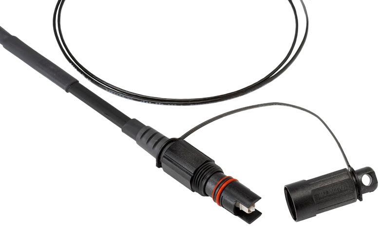
• FLATdrop peel-and-play cable allows for the outer jacket to be stripped back to expose the more flexible 3mm sub-unit, easing storage of terminated ends
• Rugged black UV resistant jacket with two fiberglass strength members gives it the strength needed for all harsh environments
• All-dielectric option allows deployment near power lines and utilities Access
• Flat drop cable construction allows for installation in buried or aerial applications
• Industry standard terminations include SC and LC (ask a Clearfield ® representative for other available connectors)
• Toneable cables allow for traceability throughout the network Investment
• Ruggedized flat drop assemblies offer an economical solution for deploying fiber in any OSP optical network
• Environmentally stable, low-insertion loss, minimal back reflection
• All assemblies are 100% tested
Fiber Cable Assemblies
FTTH Drop Cable Assemblies
Technical Specifications
FTTH Drop Cable Assemblies
Core Size and Type Singlemode
Fiber Count Single Fiber
Jacket O.D. 2.0 mm Ruggedized, 3.0 mm Peel-and-Play
Cable Types Flat Drop Loose Tube Cable, Flat Drop Peel-and-Play 3 mm (Dielectric/Toneable)
Connector Types SC/UPC, SC/APC, LC/UPC, LC/APC, HFOC/APC
Operating Temperature -40°C to 85°C (-40°F to 185°F)
Breakout Length Half meter, One Meter, Custom
Minimum Performance Specifications for Terminated Singlemode Connectors
Configured Part Numbers
Disclaimer/Note: Paper configurator shown is for reference only and should not be used to configure a saleable product configuration. All options shown on paper configurators may not be available or compatible with other options listed. Please contact your Clearfield representative for assistance in product configurations.
1
Select Cable
E = OSP, non-toneable, non-rated
M = OSP, toneable, non-rated
T = Peelable FLATdrop Non-Toneable (Non-rated)
U = Peelable FLATdrop Toneable (Non-rated)
Select Upjacketing # 1
B = 2 mm Ruggedized
K = 3mm Peel-and-Play
Z = Use if a HFOC
Select Connector # 2
Select Breakout # 2
B = 1 Meter
C = 0 5 Meter
Z = Use if a HFOC or pigtail
Select Upjacketing # 2 2
A = SC/UPC G = LC/APC
C = SC/APC W = HFOC SC/APC
E = LC/UPC
Select Connector # 1 3
Select Breakout # 1
B = 1 Meter
C = 0 5 Meter
Z = Use if a HFOC
A = SC /UPC G = LC/APC
C = SC/APC W = HFOC SC/APC
E = LC/UPC Z = Pigtail
B = 2 mm Ruggedized
K = 3 mm Peel-and-Play
Z = Use if a HFOC or Pigtail
XXXF = Length in feet XXXM or XXXF
XXXM = Length in meters
High Fiber Ribbon Breakout Kit Fiber Cable Assemblies
Application
A High Fiber Ribbon Breakout Kit is used for fiber management and routing for fusion and mechanical splicing field termination of multi-fiber ribbon cable applications in both inside and outside plant environments.
Description
Clearfield ® FieldSmart ® Ribbon Fan Out Kits are designed to breakout and manage high fiber count ribbon cables. Each 12-fiber ribbon in cable is routed into individual color-coded tubes for protection and transport into Clearview ® optimized products. The kit includes the cable body, breakout body and adhesive shrink tubing.
When ribbon fiber in excess of 144 is required, the High Fiber Ribbon Breakout Box is used in conjunction with the Ribbon Fan Out Kit for up to 864 fibers.
Features and Benefits Integrity
• Fits any manufacturer’s cable Protection
• Furcation tubing protects and manages bare ribbon fiber Access
• No special tools required
• Simple and easy breakout installs in minutes
• Easily identified individual color-coded tubing Investment
• Fan Out Kit provides protected transport path for ribbon cable to Clearview Cassettes
Technical Specifications
Pre-Configured Part Numbers
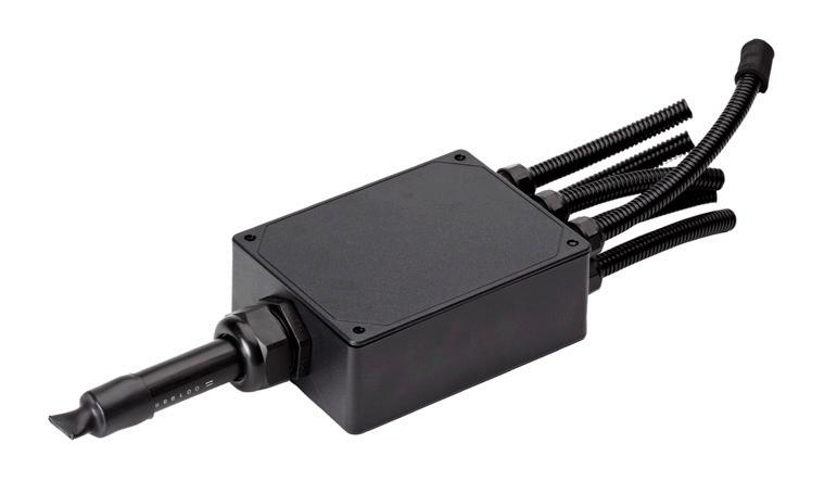
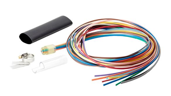
Optical Components Introduction to WaveSmart ®
Clearfield ® delivers unparalleled fiber performance with its WaveSmart optical components - custom built for the unique light requirements and interoperability needs of passive optical network splitting, fiber exhaust scenarios and coarse and dense wavelength division multiplexing. Key to the success of a fiber deployment is the performance and precision of the optical components deployed in the inside and outside plant environment. Clearfield leads the way with WaveSmart optical component technologies for PON splitting, wavelength division multiplexing and optical circulators. These products are custom built to your unique split ratios, wavelength requirements and interoperability needs.
Clearfield’s expertise in the termination of fiber ensures these components are connectorized to optimize their performance potential. Teamed with Clearfield’s experience in bend radius protection, the optimal packaging for these components is found within all Clearview ® Cassettes. In addition, Clearfield provides modular optical components packaging within an LGX footprint as well as other space saving chassis enclosures and custom discrete packages.
Specializing in the manufacturing, termination and packaging of optical components for custom-built configurations, our rapid turn-around time consistently beats the lead time quoted by our competitors for standard and custom configuration. Clearfield’s design experts can consult with you on your optical component needs and specify a solution to solve your application requirements.
By utilizing fiber optic splitters and wave division multiplexing, Clearfield’s WaveSmart optical components will save money while increasing your network’s capacity and bandwidth by creating virtual fiber without the expense of design, construction and deployment of more fiber optic cables. Splitting the light signal or separating multiple wavelengths over a single fiber allows you to increase the number of pathways within your existing fiber cable network reducing upgrade or new deployment costs. Combining Clearfield’s WaveSmart products with the FieldSmart ®, CraftSmart ® and FieldShield ® product lines, we can provide you a solution for all your applications.
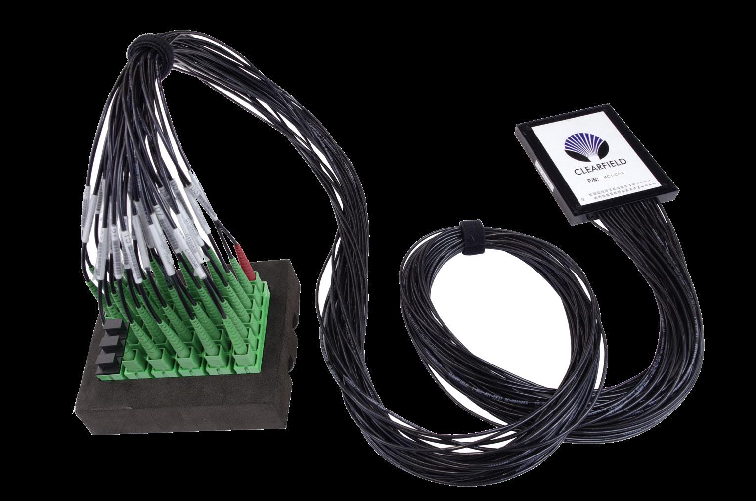

WaveSmart ® HD Splitter
Application
The Clearfield ® WaveSmart High Density Splitter is a compact splitter used in its line of FieldSmart Indoor and Outdoor Cabinets and Terminals.
Description
The WaveSmart High Density (HD) Splitter is designed to work with the FieldSmart Indoor and Outdoor Cabinets and Terminals platform. Consistent with a simple yet innovative design methodology, the WaveSmart High Density (HD) Splitter utilizes a 75% smaller package over earlier designed splitter packages.
The WaveSmart High Density Splitter uses 900 μm jacketed legs and offers superb fiber management. Clearfield ® utilizes a special outdoor rated material that not only helps control thermal expansion and contraction, but goes one step further and remains flexible at extreme temperatures down to -40°F. By making it easier to handle, there is less chance that the fiber will be routed incorrectly or that damage will occur during this process.
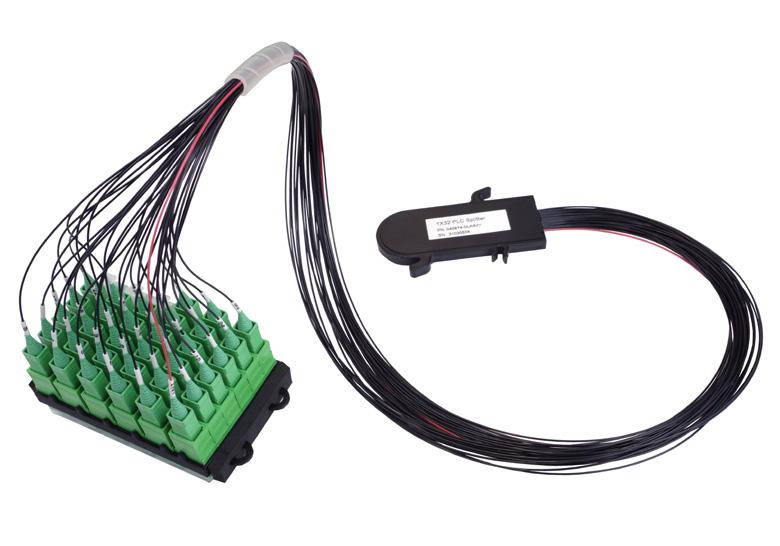
The Optical Staging Plate, the industry’s highest density product supporting ruggedized splitters in hardened environments, maximizes space for placing the optical fiber splitter legs of cabinet splitters where real estate is at a premium. Designed with performance in mind, the highly dense WaveSmart Optical Staging Plate allows for quick install and removal of splitter legs using adapters that support quick “Red Light” port testing or identification.
Features and Benefits
Integrity
• Terminations are designed and tested to Telcordia GR-326
• 100% performance tested for insertion loss/return loss and final mechanical inspection
• Optical component configuration uses devices that are compliant to Telcordia GR-1221/1209 Protection
• WaveSmart’s High Density Splitter package protects the Planar Lightwave Circuit in all environments
• Inputs and outputs protected using high quality 900 μm up-jacket Access
• Individual splitters come preloaded in staging plate for easy access and turn-up
• Each leg is 27” (685.80 mm)
• Each leg labeled for easy identification
• Red jacket on input leg Investment
• Splitter package supports one 1 x 32, two 1 x 16 or four 1 x 8 configurations without penalty in real estate or port counts
• “Grow-as-you-go” - only buy splitters as customer take rates increase
• SC/UPC or SC/APC connectors
WaveSmart ® HD Splitter
Technical Specifications
WaveSmart HD Splitters
Dimensions
mm L x 35 mm W x 6 mm H Core Size and Type Singlemode (G.657.A)
Leg Length 27” (685.80 mm)
Jacket O.D. 900um
Connector Types SC/UPC, SC/APC
Splitter Types
Operating / Storage Temp -40°C to 85 (-40°F to 185°F)
Performance Specifications
Configured Part Numbers
Disclaimer/Note: Paper configurator shown is for reference only and should not be used to configure a saleable product configuration. All options shown on paper configurators may not be available or compatible with other options listed. Please contact your Clearfield representative for assistance in product configurations.
2
1 Select (qty)/Split Ratio
1 = (1) 1x32
2 = (2) 1x16
7 = (4) 1x8
8 = (1) 1x4
3 = (2) 1x8 9 = (2) 1x4
4 = (1) 1x16 A = (4) 1x4
5 = (1) 1x8 H = (8) 1x4
6 = (3) 1x8
2 Select Connector Style
A = SC/UPC C = SC/APC
WaveSmart ® Premium Ruggedized Splitter
Application
Ruggedized Splitter for outside plant cabinet environments.
Description
The Clearfield ® WaveSmart Premium Ruggedized Splitter is the standard splitter component in its line of FieldSmart ® FSC OSP Cabinets. The splitter addresses environmental and human handling issues that other standard splitters in the industry cannot combat. It provides improved fiber protection, management and maintenance in OSP FTTx deployments.
The Optical Staging Plate, the industry’s highest density product supporting ruggedized splitters in hardened environments, maximizes space for placing the optical fiber splitter legs of cabinet splitters where real estate is at a premium. Designed with performance in mind, the highly dense WaveSmart Optical Staging Plate allows for quick install and removal of splitter legs using adapters that support quick “Red Light” port testing or identification.
Features and Benefits
Integrity
• Terminations are designed and tested to Telcordia GR-326
• 100% performance tested for insertion loss, return loss and final mechanical inspection
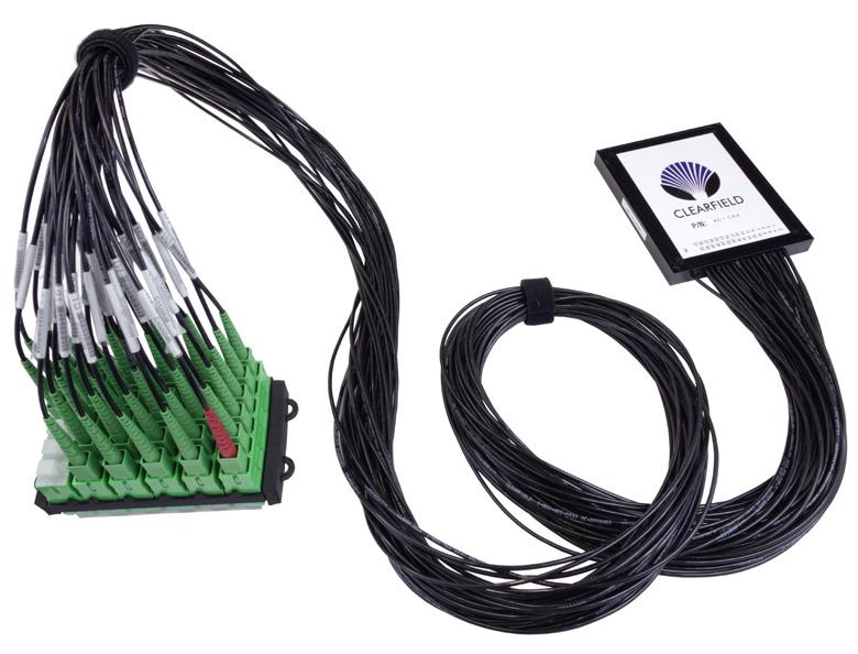
• Optical component configuration uses devices that are compliant to Telcordia GR 1221/1209 Protection
• Ruggedized jacket material of input and output legs provide superior flexibility in temperatures ranging from -55°C to 85°C (-67°F to 185°F)
• Legs will not sag or wilt at extreme temperatures or during extreme temperature cycles
• 20 year warranty Access
• Splitters legs come preloaded in staging plate for easy access and turn-up
• Fiber separators every 17” (431.80 mm) to easily recognize and prevent twisting of fiber legs
• Each leg is 51” (1295.40 mm) long and able to reach any port
• Each leg labeled for easy identification
• Red boot on input leg Investment
• Splitter package supports one 1 x 64, 1 x 32, two 1 x 16 or four 1 x 8 configurations without penalty in real estate or port counts
• Splitters can be used in:
- FieldSmart 288, 432, 576 and 1,152 PON Cabinets
- FieldSmart Wall Boxes
- FieldSmart 96 port PON-in-Ped
- FieldSmart Inside Plant PON Insert
• “Grow-as-you-go” - only buy splitters as customer take rates increase
• SC/UPC, SC/APC, LC/UPC or LC/APC connectors
WaveSmart ® Premium Ruggedized Splitter
Technical Specifications
WaveSmart Premium Ruggedized Splitters
Dimensions
Core Size and Type Singlemode (G.657.A)
Leg Length 51” (1295.40 mm)
Jacket O.D. 2.0mm
Connector Types SC/UPC, SC/APC, LC/UPC, LC/APC
Operating / Storage Temp -40°C to 85 (-40°F to 185°F)
Performance Specifications
Configured Part Numbers
Disclaimer/Note: Paper configurator shown is for reference only and should not be used to configure a saleable product configuration. All options shown on paper configurators may not be available or compatible with other options listed. Please contact your Clearfield representative for assistance in product configurations.
1 = (1) 1 x 32 7 = (4) 1 x 8
2 = (2) 1 x 16 8 = (1) 1 x 4
3 = (2) 1 x 8 9 = (2) 1 x 4
4 = (1) 1 x 16 A = (4) 1 x 4
5 = (1) 1 x 8 D = (1) 1x64
6 = (3) 1 x 8 G = (1) 1x2
Select Connector Style
= SC/UPC
= SC/APC
= LC/UPC
WaveSmart ® Industry Standard Splitter Module
Application
Upjacketed splitter for indoor and outdoor plant cabinet environments.
Description
Clearfield ® ’s WaveSmart Industry Standard Splitter is a proven component in Clearfield’s line of optical components. The splitter addresses human handling issues that other splitters in the industry cannot combat. It provides improved fiber protection, management and maintenance in FTTx deployments.
The Optical Staging Plate maximizes space for placing the optical fiber splitter legs of cabinet splitters where real estate is at a premium. Designed with performance in mind, the highly dense WaveSmart Optical Staging Plate allows for quick install and removal of splitter legs using adapters that support “Red Light” port testing for quick identification.
Features and Benefits
Integrity
• Terminations are designed to Telcordia GR-326
• 100% performance tested for insertion loss, return loss and final mechanical inspection
• Optical component configuration uses devices that are designed to Telcordia GR 1221/1209
Protection

• Splitter module package protects the discrete component while providing superior strain relief on the inputs and outputs
• 2mm jacket material of input and output legs provide protection in temperatures ranging from -40°C to 85°C (-40°F to 185°F)
• 5 year warranty
Access
• Splitters legs come preloaded in staging plate for easy access and turn-up
• Fiber separators every 17” (431.80 mm) to easily recognize and prevent twisting of fiber legs
• Each leg is 51” (1295.40 mm) long and able to reach any port
• Each leg labeled for easy identification
• Red boot on input leg
Investment
• Splitter package supports one 1 x 64, 1 x 32, two 1 x 16 or four 1 x 8 configurations without penalty in real estate or port counts
• Splitters can be used in:
• FieldSmart 288, 432, 576 and 1,152 PON Cabinets
• FieldSmart Wall Boxes
• FieldSmart 96 port PON-in-Ped
• FieldSmart Inside Plant PON Insert
• “Grow-as-you-go” - only buy splitters as customer take rates increase
• SC/UPC, SC/APC, LC/UPC or LC/APC connectors
WaveSmart ® Industry Standard Splitter Module
Technical Specifications
WaveSmart Industry Standard Splitter
Dimensions 100 mm L x 80 mm W x 10 mm H (1 x 64 = 20 mm H)
Core Size and Type Singlemode (G.657.A)
Leg Length 51” (1295.40 mm)
Jacket O.D. 2.0mm Yellow Riser Rated
Connector Types SC/UPC, SC/APC, LC/UPC, LC/APC
Types
Operating / Storage Temp -40°C to 85°C (-40°F to 185°F)
Performance Specifications
(Results do not include terminations)
Configured Part Numbers
Disclaimer/Note: Paper configurator shown is for reference only and should not be used to configure a saleable product configuration. All options shown on paper configurators may not be available or compatible with other options listed. Please contact your Clearfield representative for assistance in product configurations. K Y ____ - ____ A A 1 2
Select (Qty) / Split Ratio
1 = (1) 1 x 32 7 = (4) 1 x 8
2 = (2) 1 x 16 8 = (1) 1 x 4
3 = (2) 1 x 8 9 = (2) 1 x 4
4 = (1) 1 x 16 A = (4) 1 x 4
Select Connector Style A = SC/UPC C = SC/APC E = LC/UPC G = LC/APC 1 2
5 = (1) 1 x 8 D = (1) 1 x 64
6 = (3) 1 x 8 G = (1) 1 x 2
WaveSmart ®
Splitters
Application
These products are needed when an optical splitter or combiner is required in a central office environment. They are used in CATV headends and telephone company central offices.
Description
Clearfield ® provides Planar Lightwave Circuit (PLC) and Fused Biconic Taper (FBT) Splitters in a variety of optical component packages for the network and application need allowing carriers the ability to provide uniform fully passive signal splitting to multiple premises.
Planar Lightwave Circuit (PLC or Planar)
A light circuit on an ‘optical chip’ is mounted on a carrier and fibers, usually in ribbon form, are bonded to the edges of the chip. The assembly is encapsulated in a protective enclosure. PLC devices support direct split counts up to 64. In planar fabrication technology, devices are made using ion-exchange or photo-lithography techniques that replicate solid-state circuit methods. Ultimately, the per-unit cost for the expected high volumes will become advantageous for planar technology, especially for higher port devices. A difficult manufacturing problem involves a low-loss method for attaching the optical fibers to the chip and then passing the market’s qualification and reliability requirements.
Fused Biconic Taper (FBT)
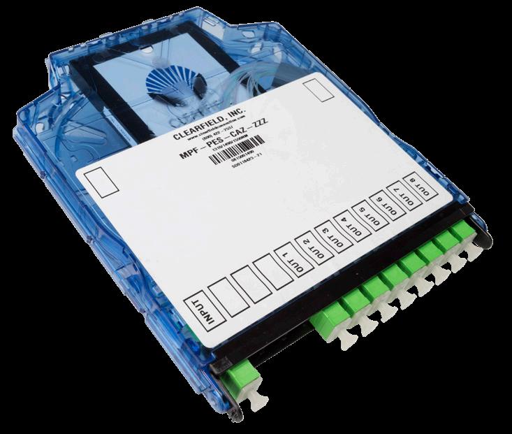
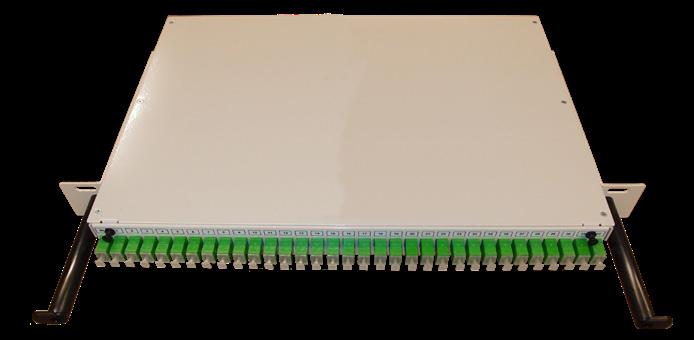
Two or more fibers are twisted together, heated and drawn to bring the optical cores into near contact. The combined fibers are mounted on a low-expansion carrier and encapsulated in a low expansion tube. FBT devices allow direct splitting up to 32 ways. Higher split counts are achieved by splicing multiple devices to form multi-stage, concatenated splitters. Concatenated splitters are also called tree splitters. The fused biconic tapered technology directly bonds or melts the fibers together so that the final splitter can be mounted in small diameter (approximately 3-millimeter) stainless-steel tubes. This technology produces small, low-cost, highperformance devices. A tough fabrication obstacle involves the small and delicate final coupling region. However, when properly mounted and packaged, these devices meet long-term stability and reliability requirements.
Packaging Options
• Clearview ® Cassette
• Clearview xPAK
• Discrete (unpackaged solution)
Features and Benefits Integrity
• 1 RU Splitter/Pizza Box
• LGX
• Terminations are designed and tested to Telcordia GR-326
• Supports industry standard SC and LC singlemode and multimode connectors
• 100% performance tested for insertion loss, return loss and final mechanical inspect Protection
• Ruggedized, secure packaging
• Non-removable adapter plates Access
• Front and rear access to panel Investment
• FieldSmart ® Optical Components offer an economical, dense and user-friendly solution for deploying splitters or WDMs in a central office design
• Virtually any combination of split ratios and number of components can be achieved in one of the four Clearview Cassette sizes
• Clearfield supports legacy splitter deployments by offering optical components in LGX footprint
• 1 RU optical components available for smaller, limited deployments
• Environmentally stable, high isolation, low insertion loss
• Compliant to Telcordia GR-1221 and GR-1209
1RU Splitter/Pizza Box
WaveSmart ® Splitters
Technical Specifications
Planar Lightwave Circuit Splitters
Fused Biconic Taper Splitters
Packaging Dimensions
WaveSmart ®
Splitters
Configured Part Numbers
Disclaimer/Note: Paper configurator shown is for reference only and should not be used to configure a saleable product configuration. All options shown on paper configurators may not be available or compatible with other options listed. Please contact your Clearfield representative for assistance in product configurations.
1 Select Packaging
A = LGX – vertical - 1 wide
B = LGX – vertical - 2 wide
D = LGX – vertical - 4 wide
E = FieldSmart FxMP – 6 high
G = 1.75" (44.45 mm)(1 RU) - 19" brackets (482.60 mm)
H = 3.50" (88.90 mm)(2 RU) - 23" brackets (584.20 mm)
S = Clearview Blue – 1 high
T = Clearview Blue – 2 high
U = Clearview Blue – 3 high
Y = Clearview Blue – 6 high
7 = FieldSmart FxMP – 1 high
8 = FieldSmart FxMP – 2 high
9 = FieldSmart FxMP – 3 high
Select Input / Output Select Optical Type
= Planar splitter
= FBT splitter
4 Select Connector
A = SC/UPC
B = SC/UPC DX
C = SC/APC
D = SC/APC DX
E = LC/UPC
G = LC/APC
5 # of Components Per Package
WaveSmart ® Wave Division Multiplexing (WDM)
Application
These products are needed when a passive multiplexing or demultiplexing unit is required in a central office environment. They are used in CATV headends and telephone company central offices.
Description
Wavelength Division Multiplexing increases fiber capacity by combining (mux) and separating (demux) multiple input channels over a single fiber output. Wavelength division multiplexers let you expand the bandwidth of optical communication networks and can be used at several locations within each network. Clearfield ® provides WDMs for singlemode fiber applications.
Coarse Wavelength Division Multiplexing
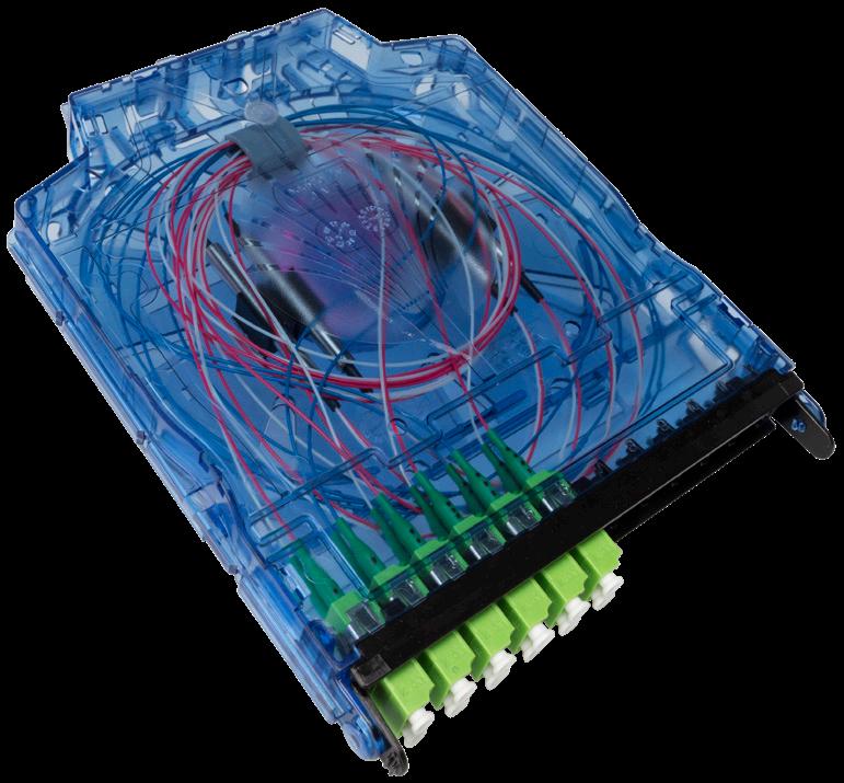
CWDMs combine or multiplex more than one wavelength over one fiber. This is done by using fiber pigtail collimators and wavelength/light filters that are aligned and mounted in a glass tube and typically packaged in a stainless steel tube for more protection. The wavelength/light filters used only allow specific wavelengths of light to pass through the filter and the remainder of the wavelengths to be reflected back. CWDMs can also be used to separate or demultiplex more than one signal using the same device and transmitting the signal in the opposite direction. CWDMs have channel spacing of 20nm with a working channel passband of +/-6.5nm from the wavelengths center. This allows you to add multiple wavelengths on to one fiber while keeping within the operating wavelengths of 1260nm to 1620nm. The wavelengths used are defined by the International Telecommunications Union; reference ITU G.694.2 for the ITU CWDM Wavelength Grid. Note: as of June 2002, 18 center wavelengths, from 1270nm to 1610nm, were listed.
Dense Wavelength Division Multiplexing
Dense Wavelength Division Multiplexing or DWDM is a technology which multiplexes or demultiplexes a number of optical carrier signals onto a single optical fiber by using different wavelengths (i.e. colors) of laser light. This technique enables bidirectional communications over one strand of fiber, as well as multiplication of capacity. DWDM signals within the 1550nm band which are wavelengths between approximately 1530–1565nm (C band) and/or 1570–1625nm (L band) adhering to the DWDM ITU-T G.694.1 frequency grid. DWDMs allow you to increase your wavelength capacity. DWDM products can offer multiplexing of multiple channels using 200 GHz and 100 GHz spacing with the option to have an added Expansion port and/or Monitor port. All of the Clearfield Passive Products are Telcordia GR-1209 and GR-1221 certified.
Packaging Options
• Clearview ® Cassette
• Clearview xPAK
• Discrete (unpackaged solution)
Features and Benefits
Integrity
• Compliant to Telcordia GR-1221
• Consistent performance
Protection
• Wide operating temperature range
• Low polarization sensitivity
• No epoxy in optical path
Access
• Transport protocol independent
• Low insertion loss
• Minimal optical loss
Investment
• Wide bandwidth (CWDM/DWDM)
• Mux, demux and universal options available
• PDL = < 0.2 dB
• Return Loss = > 45 dB
• Pizza Box
• LGX
WaveSmart ®
Wave Division Multiplexing (WDM)
Technical Specifications
FSAN WDM Specifications
WaveSmart ® Wave Division Multiplexing (WDM)
200 GHz DWDM
WaveSmart ®
Wave Division Multiplexing (WDM)
WaveSmart ® Wave Division Multiplexing (WDM)
WaveSmart ®
Wave Division Multiplexing (WDM)
Configured Part Numbers

1 Component Package
A = Discrete – 250 µm (0.5 meter legs)
B = Discrete – 250 µm (1 meter legs)
C = Discrete – 900 µm (0.5 meter legs)
D = Discrete – 900 µm (1 meter legs)
E = Discrete – 2 mm rugged (0.5 meter legs)
F = Discrete – 2 mm rugged (1 meter legs)
G = xPAK (no longer used, see N or O)
H = LGX
M = Pizza box/1 rack unit
N = xPAK LGX front panel
O = xPAK standard panel
P = LGX Blade
Q = Module 100x80x10 mm – 900 µm (0.5 meter legs)
R = Module 100x80x10 mm – 900µm (1 meter legs)
S = Module 100x80x10 mm – 2 mm (0.5 meter legs)
T = Module 100x80x10 mm – 2 mm (1 meter legs)
U = Module 100x80x10 mm – 2 mm (51 inch legs)
V = Module 100x80x13 mm – 2 mm (51 inch legs)
W = Clearview Blue 1 high – no mounting ears
Y = Clearview Blue 1 high – mounting ears
1 = 80x60x7 mm – 900 µm – 0.5 meter legs
2 = 80x60x7 mm – 900 µm – 1 meter legs
1 2 3 4 6 7 5
Device Type
A = Add / drop CWDM
B = CWDM

A = Included Z = N/A 8 9
C = DWDM (50 or 100 Ghz)
D = DWDM (200 Ghz)
E = 1310 / 1550 WDM
F = 1310 / 1490 / 1550 FSAN WDM
G = Circulator
H = Drop only CWDM
3 2 Select Connector Style
A = SC/UPCE = LC/UPC
C = SC/APC G = LC/APC
Z = N/A

Number of Components
A = 1 E = 5
B = 2 (Quad)F = 6
C = 3 G
5 Number of Channels
XX = # of channels
6 1310 Port
A = Included Z = N/A 7 Expansion Port
A = 1% incoming
B = 2% incoming
C = 3% incoming
D = 5% incoming
E = 7% incoming
F = 10% incoming
G = 1% out going
H = 2% out going
J = 3% out going
K = 5% out going
L = 7% out going
M = 10% out going
Z = N/A
8 Start Channel Test Port
9
XX = Channel
Z = N/A

10 Application
M = Channel
D = N/A
M/D = Mux & demux
M/M = Mux & mux
D/D = Demux & demux
U = Universal
WaveSmart ® VOA and Patch Cord Splitter
Application
A variable optical attenuator (VOA) is a device designed to attenuate an intensity or power level of an input optical beam in a controlled manner to produce an output optical beam with different attenuated intensities. Variable optical attenuators play an important role in the implementation of modern information networks having optical interconnects. In fiber optic communication systems, variable optical attenuators are broadly employed to regulate the optical power levels to prevent damages to the optical receivers caused by irregular optical power variations.
Fiber optic patch cord splitters are optical devices that connect three or more fiber ends, dividing one input between two or more outputs or combining two or more inputs into one output
Description
Clearfield ® VOA and Patch Cord Splitters are optical components that are up-jacketed to 3 mm and terminated with any industry standard connectors.
Features and Benefits Integrity
• Compliant to Telcordia GR-1221 and GR-1209
• Supports Industry standard Singlemode and Multimode fibers and connectors
• Outside plant hardened components Protection
• Ruggedized fiber up-jacket and packages available for superior protection
• Multi-component custom packages available Access
• Compact tube style and discrete components offered for direct splice in options
• VOA input available with up to one meter and output leg up to 30 meters
• Up to 80 dB attenuation on VOA
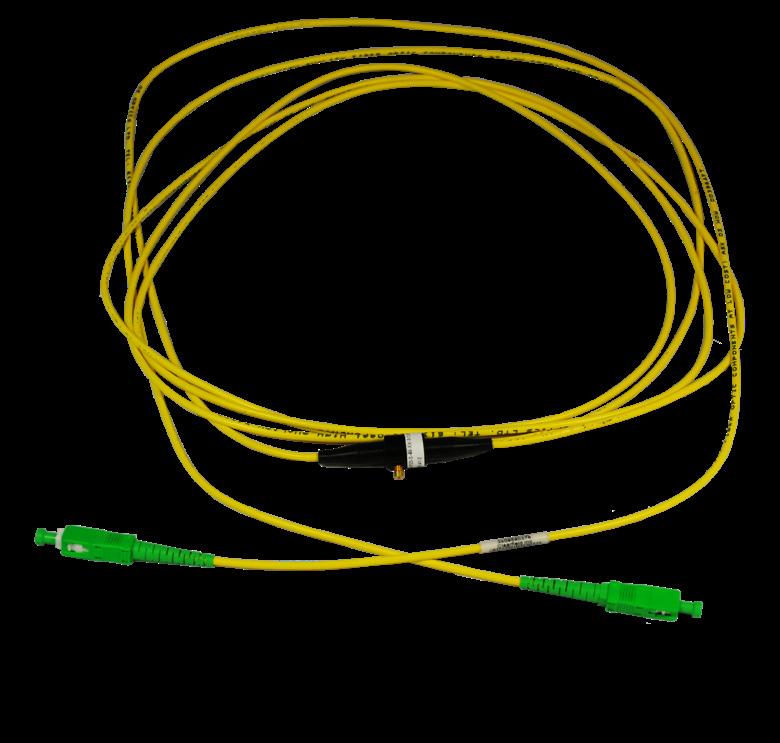
• Patch Cord Splitters available with up to one meter for input and nine meters on the outputs Investment
• WaveSmart VOA and Patch Cord Splitters offer an economical, dense and user-friendly solution for deploying fiber in any optical network
• Environmentally stable, high-isolation, low-insertion loss
• All components tested 100% and include test documentation
Technical Specifications
WaveSmart VOA and Patch Cord Splitter
VOA 12 mm round x 15 mm L
Patch Cord Splitter 90 mm L x 20 mm D x 10 mm H
Environmental Reliability Tests
• Complies with Telcordia requirement TR-NWT-0012 21 and TR-NW T-00 1209
- Optical characteristics
- Thermal Cycling
- Vibration Test
- Salt Spray Erosion
- Thermal Aging
- Humidity Resistance
WaveSmart ®
VOA and Patch Cord Splitter
VOA
and Patch
Cord Splitter - Environmental Reliability Tests
High Temperature Storage Test 85°C for 2,500 hours
Low Temperature Storage Test -40°C for 2,500 hours
Thermal Cycling Test -40°C/ 75°C for 500 cycles
Fiber Pulling Test 0.25 Kg for 250 μm fiber and 900 μm loose tube
Water Immersion Test 43°C, PH=5.5, for 340 hours
Vibration Test
10~2,000 Hz Random, 20 g, three axes
Impact Test 8 Drops, 1.8 meters high
Thermal Shock Test 100°C
Variable Optical Attenuator Specifications
These attenuators are designed to meet Telcordia standards. These attenuators can be used for 1300nm and 1550nm, as well as for C (15201570nm), L (1570-1620nm) and S (1470-1520nm) bands, with minimal changes in the insertion loss. Mounting holes provide easy attachment to PC boards and patch panels.
The attenuators consist of two base plates. Each base plate contains a fiber followed by a collimating lens. The attenuator is pre-aligned for optimum coupling efficiency using a patented tilt alignment technique. A threaded radial screw is used to block the collimated beam between the two lenses. Because the attenuator works by directly blocking the beam, it is polarization insensitive. A seal cap is used to seal the junction against temperature and humidity effects. The attenuator can even withstand immersion in water for extended periods of time. Attenuators are offered with singlemode, multimode or polarization maintaining fibers.
Configured Part Numbers
Disclaimer/Note: Paper configurator shown is for reference only and should not be used to configure a saleable product configuration. All options shown on paper configurators may not be available or compatible with other options listed. Please contact your Clearfield representative for assistance in product configurations.
1
A =
Select Attenuator Type
E
4 Select Output Connector # 2
A = SC/UPC
C = SC/APC E = LC/UPC
G = LC/APC Z = N/A XXX = Length required from end of input connector to the attenuator / splitter
G = LC/APC 5 Select Length of Input Leg
7 Select Length of Output Leg # 1 **
XXX = Length required from end of output connector # 1 to the attenuator / splitter
9 Select Length of Output Leg # 2 **
XXX = Length required from end of output connector # 2 to the attenuator / splitter
VOA
* The maximum length from the input connector to the VOA cannot exceed 1 meter.
** The maximum length from the output connectors to the VOA cannot exceed 29 meters.
Overall length of a VOA patchcord cannot exceed 30 meters.
Splitter
* The maximum length from the input connector to the splitter cannot exceed 1 meter.
** The maximum length from the output connectors to the splitter cannot exceed 9 meters.
Overall length of a splitter patchcord cannot exceed 10 meters.
WaveSmart ® ½ Wide LGX Modular Optical Components
Application
This product is needed when an optical splitter or WDM is required in a central office environment. They are used in CATV headends and telephone company central offices.
Description
Modular optical components are splitters or WDMs that are packaged inside this metal housing with three duplex SC adapters or three quad LC female adapters for a total of 12 ports. The LGX modules utilizes a 6” (152.40 mm) high Optical Component Chassis to house the modules in a frame and can hold up to 29, ½ wide LGX.
Features and Benefits
Integrity
• Compliant to Telcordia GR-449
• Supports industry standard LC adapters Protection
• Ruggedized, secure packaging Access
• Front inputs and outputs
Investment
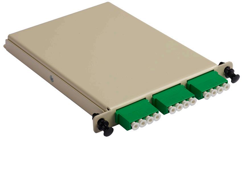
• FieldSmart ® Optical Components offer an economical, dense and user-friendly solution for deploying splitters or WDMs in a central office design
• Any combination of split ratios and number of components up to 12 ports
• Clearfield ® supports legacy splitter deployments by offering optical components in LGX footprint
• Environmentally stable, high-isolation, low-insertion loss
• Compliant to Telcordia GR-1221 and GR-1209
Technical Specifications
Port Density
SC: 6 (3 dual SC adapters); LC: 12 (3 quad LC adapters)
Connector Types SC/UPC, SC/APC, LC/UPC, LC/APC
Optical Component Types WDMs, FSAN-WDMs, CWDMs, Splitters
Splitter Types 1 x 8, 1 x 4
Panel Type 6” (152.40 mm) LGX Optical Component Chassis
Material 16 gauge cold rolled steel with almond powder coating
WaveSmart ® Build-Out Attenuators
Application
Fiber optic attenuators are designed to introduce a specific amount of signal loss into an optical circuit. These products provide attenuation at a mated pair connection and are used for signal budgeting and power equalization.
Description
Clearfield ® provides both build-out and in-line attenuators in all industry standard interface and attenuation values.
Features and Benefits
Integrity
• Compliant to Telcordia GR-910 and GR-1221
• Supports Industry standard Singlemode connectors
• Outside Plant hardened components
Protection
• Male and female ends all have protective dust cap
• Individually packaged for protection and to eliminate product mix up
Access
• Compact style fits in most cabinets and panels
• Connector interface includes SC, SC/APC, LC, LC/APC
• 1 dB through 20 dB, 25 dB and 30 dB attenuation
• Dual Bandwidth 1310/1550nm Supported
• Attenuation levels clearly marked for easy identification
Investment
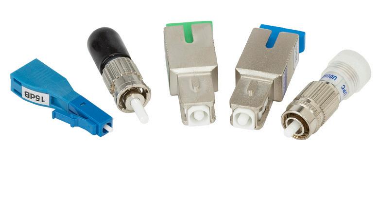
• WaveSmart Attenuators offer an economical, dense and user-friendly solution for deploying fiber in any optical network
• Environmentally stable, high-isolation, low-insertion loss
• All components are tested 100%
Technical Specifications
Configured Part Numbers
Disclaimer/Note: Paper configurator shown is for reference only and should not be used to configure a saleable product configuration. All options shown on paper configurators may not be available or compatible with other options listed. Please contact your Clearfield representative for assistance in product configurations.
Copper Cable Assemblies Introduction to Copper Products
A copper cable assembly is only as good as its parts and at Clearfield ®, we only use the best parts available.
Whether it’s a custom cabling solution that integrates with technologies for the world’s most demanding semiconductor manufacturer or the data center for one of the Internet’s top search engine companies, Clearfield takes your copper cabling requirements seriously. Combining 40+ years of experience, we can design and manufacture DS1, Telco, CAT5e and CAT6 patch cords and cable assemblies for just about any application.
We’ve earned a reputation for product quality and customer service by producing value-priced, high-quality product delivered to your schedule. From concept, to production floor, to your doorstep, our in-house engineering and design staff will work with you to tailor-engineer a solution that matches both your performance and cost requirements. Clearfield’s connectivity expertise, combined with a personalized approach, gives our customers the highest level of service and quality.
Copper Termination Manufacturing Capabilities
All manufacturing is carried out under controlled conditions based on documented workmanship standards, product specifications, work instructions and QA inspection criteria. At Clearfield, we use the latest manufacturing processes combined with hands-on expertise and craftsmanship for each assembly we build.
Soldering, crimping and IDC termination can be performed on all types of cables, wire harnesses and electromechanical assemblies for a variety of high technology industries, such as telecommunication, computer, medical, military, automotive and industrial electronics. Electromechanical assembly capabilities include electronic sub-assemblies and complete product assemblies and test, using available inhouse or customer-supplied fixtures and test equipment. We invite short run projects, as well as, high volume production runs.
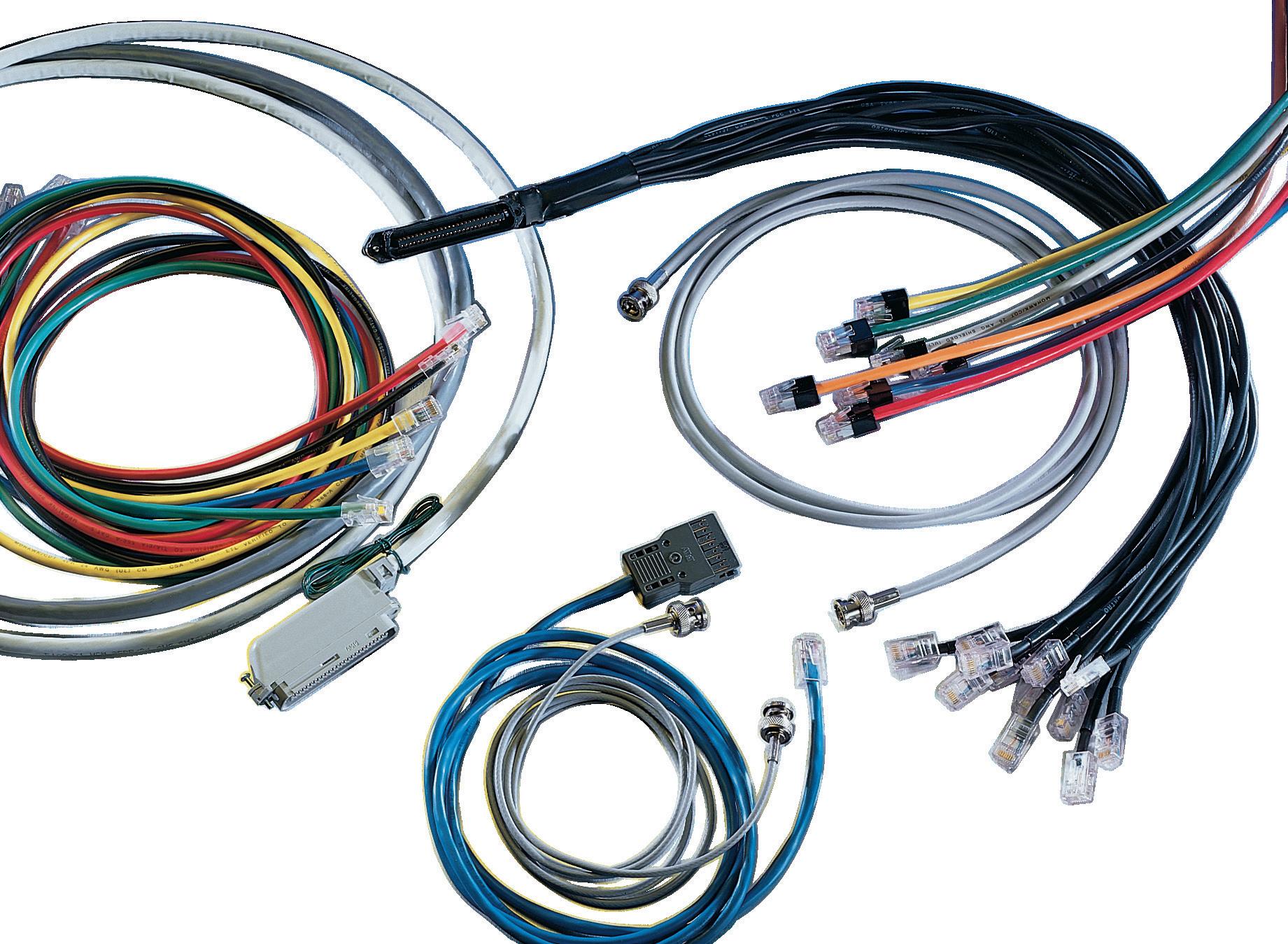

Copper DS1 Copper Cables
Application
Copper DS1 assemblies connect a variety of equipment.
Description
DS1 assemblies are typically constructed using 28 or 32 pair cable and 64 position connectors.
Features and Benefits
Integrity
• Meets or exceeds EIA/TIA standards for data transmission
• Meets UL, CSA, and NEC standards
• RoHS and WEEE compliant
• 100% visually and mechanically inspected
• 100% electrically tested
Protection
• Custom lengths MP 10/15/15 to minimize cable pile up
• Optional PVC and Plenum jackets available Access
• 90°, 120°, and 180° male and female interfaces available Investment
• CAT 5e available through special order
• Stock and custom serialization and labeling
• Stock and custom lengths available
• Custom pin outs available

Copper DS1 Copper Cables
Configured Part Numbers
Disclaimer/Note: Paper configurator shown is for reference only and should not be used to configure a saleable product configuration. All options shown on paper configurators may not be available or compatible with other options listed. Please contact your Clearfield representative for assistance in product configurations. D 1 R - - XXXM or XXXF 1
6 2 3 5 4 7
Select Cable Type
1 = 28 pr, 24 ga, shielded, solid
3 = 32 pr, 24 ga, shielded, solid
4 = 28 pr, 22 ga, shielded, solid
5 = 28 pr, 26 ga, shielded, solid
6 = 32 pr, 26 ga, shielded, solid
7 = 32 pr, 22 ga, shielded, solid
9 = 32 pr, 26 ga, shielded, solid, cat 5, VDSL
2 Select Wiring Configuration
6 = Straight through
X = Custom
1 3
Select Connector # 1
A = 64 pos, male, 24-26 ga, 180 deg
B = 64 pos, female , 24-26 ga, 180 deg
C = 64 pos, male, 24-26 ga, 180 deg, bail lock
E = 64 pos, male, 24-26 ga, 90/270 deg
F = 64 pos, female , 24-26 ga, 90/270 deg
G = 64 pos, male, 24-26 ga, 90/270 deg, bail lock
I = 64 pos, male, 22 ga, 90/270 deg
J = 64 pos, male, 22 ga, 180 deg
K = 64 pos, female , 22 ga, 90/270 deg
L = 64 pos, female , 22 ga, 180 deg
Select Cable Exit Connector # 1
1 = Pins 1 – 33
2 = Pins 32 – 64
Z = Exit not required (180 degree connector )
5 4 7
Select Connector # 2
A = 64 pos, male, 24-26 ga, 180 deg
B = 64 pos, female , 24-26 ga, 180 deg
C = 64 pos, male, 24-26 ga, 180 deg, bail lock
E = 64 pos, male, 24-26 ga, 90/270 deg
F = 64 pos, female , 24-26 ga, 90/270 deg
G = 64 pos, male, 24-26 ga, 90/270 deg, bail lock
I = 64 pos, male, 22 ga, 90/270 deg
J = 64 pos, male, 22 ga, 180 deg
K = 64 pos, female , 22 ga, 90/270 deg
L = 64 pos, female , 22 ga, 180 deg
Z = Pigtail/Blunt
6 Select Cable Exit Connector # 2
1 = Pins 1 – 33
2 = Pins 32 – 64
Z = Exit not required (180 degree connector )
Select 24 " Drain Wire
1 = Connector 1 drain wire
2 = Connector 2 drain wire
3 = Drain wire both connectors
0 = No drain wires
XXXM or XXXF
XXXM = Length in meters
XXXF = Length in feet
Copper Telco Copper Cables
Application
Copper telco assemblies connect a variety of equipment interfaces in carrier networks, private networks and customer premise environments. They are used to transmit analog or digital data for a variety of communication applications. Our high-quality cables ensure the integrity of your data path.
Description
Clearfield ® 25/32-pair cables, terminated to 50/64-position RJ connectors, are manufactured to EIA/TIA standards. Our 25-pair Category 5e assemblies meet standards for data transmission up to 100 mbps.
25 pair 50 pin assemblies plug into many types of gear. Please specify when ordering what gear, if known, the connectorized ends will be plugging into to ensure the proper screws are included with the assembly.
Clearfield maintains a copper connectivity library for various manufacturing of active equipment and can provide assembly information specific to your connectivity needs.
Features and Benefits
Integrity
• Meets or exceeds EIA/TIA standards for data transmission
• Meets UL, CSA, and NEC standards
• RoHS and WEEE compliant
• 100% visually and mechanically inspected
• 100% electrically tested Protection
• Custom lengths MP 10/15/15 to minimize cable pile up
• Optional PVC and Plenum jackets available Access
• 90°, 120°, and 180° male and female interfaces available
• Octopus/Hydra assemblies available Investment
• MP 10/15/15
• Stock and custom serialization and labeling
• Custom pin outs available

Copper Telco Copper Cables
Configured Part Numbers
Disclaimer/Note: Paper configurator shown is for reference only and should not be used to configure a saleable product configuration. All options shown on paper configurators may not be available or compatible with other options listed. Please contact your Clearfield representative for assistance in product configurations.
Select Cable Type
1 = Cat 5, 25 pr, 24 ga, PVC
2 = Cat 3, 25 pr, 24 ga, PVC, BC
3 = Cat 1, 25 pr, 24 ga, PVC, TC
5 = Cat 3, 25 pr, 24 ga, plenum , shielded
6 = Cat 3, 25 pr, 24 ga, plenum
7 = Cat 1, 25pr, 24 ga, PVC, shielded
8 = Cat 5, 25 pr, 24 ga, PVC, shielded
9 = Cat 5e, 25 pr, 24 ga, PVC
A = Cat 5e, 25 pr, 24 ga, plenum
B = Cat 5e, 25 pr, 24 ga, plenum , shielded
D = Cat 5, 25 pr, 24 ga, PVC, blue
Select Wiring Configuration
4 = 10 / 100 Base T
6 = Straight through
9 = Custom
* Cat 3 and Cat 5 connector notes :
Cat 5 female connectors only come in 90 degree The cable exit for must be 25-50
A = Cat 5, male, 180 deg
B = Cat 5, male, 90 deg
C = Cat 3, female , 180 deg
D = Cat 5, female , 90 deg
E = Cat 5, male, 110 deg
F = Cat 3, male, 90 / 270 deg
G = Cat 3, male, 180 degree
H = Cat 3, female , 90 / 270
I = Cat 3, male, 90 deg, shielded
J = Cat 3, female , 90 deg, shielded
K = Cat 5, Champ Sys 5, male, 90 / 270 deg
Z = Blunt Select Connectors *
Select Cable Exits
Cat 5 male connectors come in 90, 110 and 180 degree The cable exit for the 90 degree must be 1-26 The 110 degree must be specified, 1-26 or 25-50
Select Screw Length ****
1 = Standard screw
2 = 1 00' screw
3 = 1 25" screw
4 = 1 50" screw
5 = 0 75" screw
6 = 0 425" screw
7 = 1 75" screw
8 = 0 875" screw
B = Bail locks
Z = Not required
Select Drain Wire ***
1 = Yes – need drain wire 0 = No – do not need drain wire Z = N / A
XXXM = Length in meters
= Length in feet
Cat 3 male and female connectors mainly come in 90 and 180 degrees Standard cable exit for male 90 degree is 1-26 For a male 270 degree cable the exit needs to be 25-50 Standard cable exit for female
90 degree is 25-50 For a female 270 degree cable the exit needs to be 1-26
** Use option Z for 180 degree connectors For additional cable exit details see above
*** Drain are only required for shielded connectors For non-shielded connectors use option Z
**** 25 pr / 50 pin assemblies plug into many types of gear Please specify when order what gear , if known , the connectorized ends will be plugging into to ensure the proper screws are included with the assembly
Copper CAT5e and CAT6 Patch Cords
Application
Category 5e and 6 copper patch cords connect a variety of equipment interfaces in both carrier and private networks, as well as customer premise environments.
Description
These patch cords provide physical mated connections between components in 10BASE-T, 100BASE-T and 155 Mbps ATM networks. Clearfield ® offers Category 5e and 6 copper patch cords with UTP cable and 8-conductor connectors manufactured to EIA/TIA standards.
Features and Benefits
Integrity
• Meets or exceeds EIA/TIA 568 B.2 MP 10/15/15
• RoHS and WEEE compliant
• ETL verified
• UL Listed
• 100% tested for continuity and performance Protection
• Strain relief boots Access
• Latch guards with easy thumb depression
• Nine stocked colors with custom configurations available Investment
• Stock and custom serialization and labeling
• Stock and custom lengths available

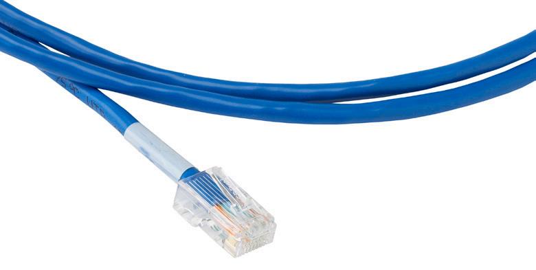
Copper CAT5e and CAT6 Patch Cords
Configured Part Numbers
Disclaimer/Note: Paper configurator shown is for reference only and should not be used to configure a saleable product configuration. All options shown on paper configurators may not be available or compatible with other options listed. Please contact your Clearfield representative for assistance in product configurations.
CAT5e Patch Cords
1
0 = Black (PVC)
1 = White (PVC)
2 = Purple (PVC)
4 = Red (PVC)
5 = Green (PVC)
6 = Blue (PVC)
7 = Gray (PVC)
8 = Orange (PVC)
9 = Yellow (PVC)
A = Light gray (plenum )
B = Dark gray (plenum )
C = Black (plenum )
D = White (plenum )
E = Red (plenum )
F = Yellow (plenum )
G = Green (plenum)
H = Blue (plenum )
CAT6 Patch Cords C T 6 - - N T -
0 = Black (PVC)
1 = White (PVC)
2 = Purple (PVC)
4 = Red (PVC)
5 = Green (PVC)
6 = Blue (PVC)
7 = Gray (PVC)
8 = Orange (PVC)
9 = Yellow (PVC)
A = Black (plenum )
B = White (plenum)
E = Red (plenum )
F = Green (plenum)
G = Blue (plenum )
H = Light gray (plenum )
K = Yellow (plenum )
or XXXF
* Standard patchcords use stranded, non -
1 = 568A
3 = 568A crossover
B = 568A – certified cat 6
D = 568A crossover – certified cat 6 Select Wiring Configuration
or XXXF
XXXM = Length in meters
= Length in feet
* Standard patchcords use stranded, non -
Engineering Standards and Technology
Inspect then Connect Cleaning Instructions
Inspect and clean EVERY connector before inserting into adapter.
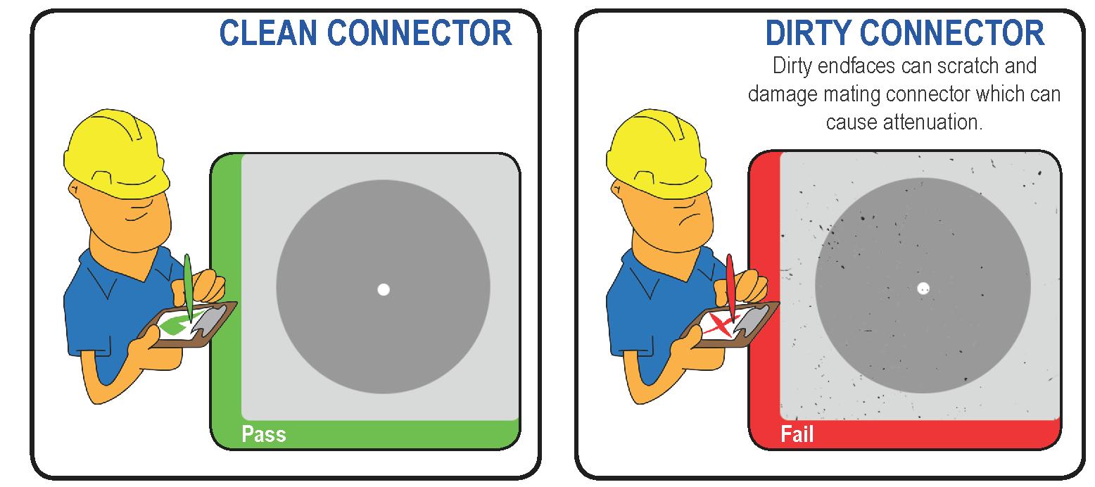
• Ferrule and V-groove cleaning swab 50/tube
• SFF Connector Flat Swab 500/bag
LC Cleaning Kit CleanKit-LC-01
• 1.25mm ferrule swab (LC) 50/tube
• Portable platform 400perforated/box
• Fiber Wash MX Precision Cleaner Pen
• Ferrule and V-groove cleaning swab 50/tube
• SFF Connector Flat Swab 500/bag
SC Cleaning Kit CleanKit-SC-01
• 2.5mm foam swab SC only 50 per tube
• Portable platform 400perforated/box
• Fiber Wash MX Precision Cleaner Pen
Engineering Standards and Technology Inspect then Connect Cleaning Instructions
Connector Cleaning Procedure
Whether factory terminated or field spliced, clean connectors are essential for proper system operation. Even the smallest dust particle can cause transmission problems, so for optimal network performance inspect, and if necessary, clean connectors and adapters prior to mating.
Inspect Then Connect
These are Clearfield recommended products/applications. Use the product you feel will complete your cleaning procedures. Create a “best practice” for your company and follow those procedures.
The use of Chemtronics end face and bulkhead cleaning products and techniques ensures a clean end face, no matter the type of contamination.
Before cleaning any connector, be sure you know what type of contaminate you are cleaning (dry, fluidic, or combination). All the available products are good, it’s the process that you need to be aware of. Using a dry cleaning method to clean “dirt” can lead to scratching of the end face. Learn the process of cleaning properly.
Note: It is NOT recommended to use isopropyl alcohol to clean the end face.
Cleaning an SC/LC Connector
Cleaning the End Face
• Place one wiping paper on QbE-2 FiberSafe™ Cleaning Platen. (Figure 1)
• Apply small amount of precision cleaner (about 1” in diameter) with Electro-Wash MX pen on to one end of the wipe. (Figure 2)
• Hold end face at a 90 degree angle. For APC connection, adjust by slightly tilting the container or end face. Angle is correct when no drag is felt on the end face. (Figure 3)
• Draw end face from wet to dry part of the wipe 3 times. Use just enough pressure to ensure complete contact between end face and the wipe.
Note: DO NOT retrace previous step.
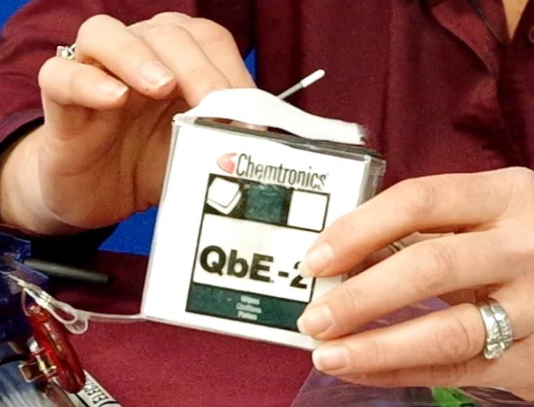
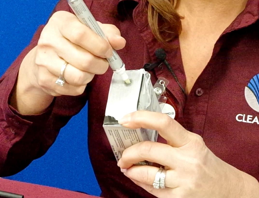
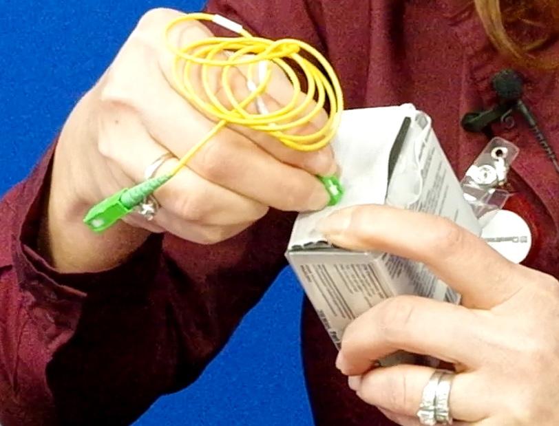
Figure 1 Figure 2
Figure 3
Engineering Standards and Technology Inspect then Connect Cleaning Instructions
Cleaning the Ferrule
• Lightly moisten the fiber optic swab (2.5mm/38542F or 1.25mm/38040) by spotting a small amount (about 1”) of Electro-Wash PX or Electro-Wash MX pen onto the QbE. Hold the swab, 1 side down to the wetted area and hold for a count of 1-2-3-4-5. (Figure 4)
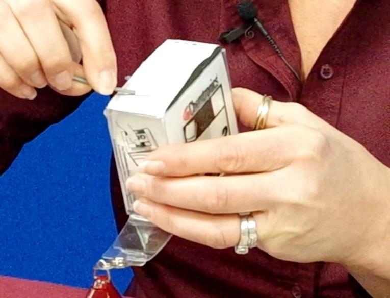
• Insert swab into side of ferrule, wet side to the ceramic ferrule and circle around 2-3 times and remove. Turn swab to dry side and repeat. (Figure 5)
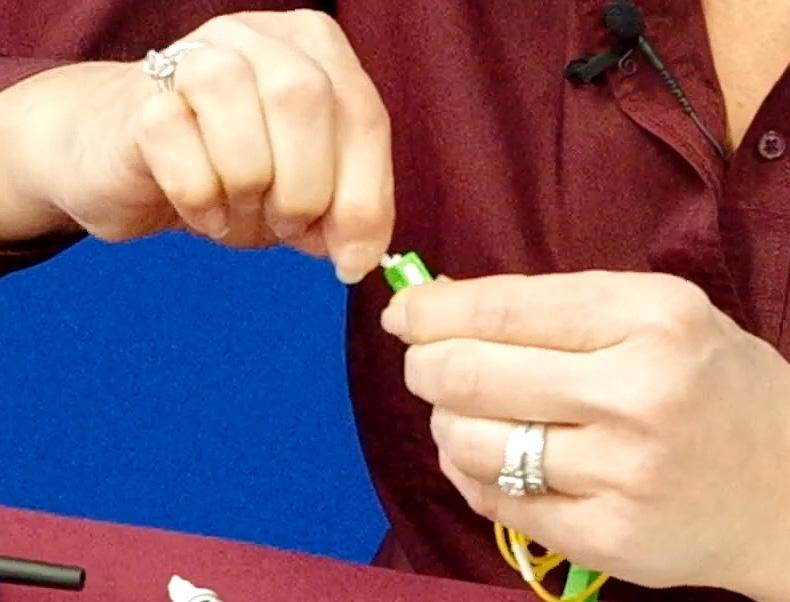
Cleaning the Mate Through an Adapter AND the Adapter Itself
• Lightly moisten the fiber optic swab (2.5mm/38542F or 1.25mm/38040) by spotting a small amount (about 1”) of Electro-Wash PX or Electro-Wash MX pen onto the QbE. Hold the tip of the swab onto the wetted area and hold for a count of 1-2-3-4-5.
• Insert the swab into the adapter to the connector, press lightly against the connector, twist 2-3 times, remove and discard.
• Dry with a second dry swab.
• Inspect, repeat cleaning if necessary, and test for signal strength.
• Use additional swabs to clean inside the actual adapter. Moisten swab, like above, and insert through hole and remove while twisting. (Figure 6)

Figure 4
Figure 5
Figure 6
Engineering Standards and Technology Inspect then Connect Cleaning Instructions
Cleaning an MPO/MTP Connector
Male Connector
• Use of Chemtronics MTP Connector Cleaning Swabs (CC505F) is recommended. Even after cleaning with a probe cleaner, you should always clean the pins with this (or an equivalent) type swab. Cleans ALL MTP/MPO connector end faces. This swab also cleans the “pins” of the male connector
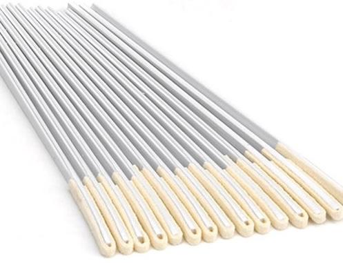
• Lightly “spot” a QbE-2 wipe on the platen with Electro-Wash PX Fiber Optic Cleaner, the FiberWash or MX Pen.
• Lightly touch short side of the MTP/MPO Connector Swab to the wetted area (3-5 secs) to absorb some cleaning solution (DO NOT over saturate the swab).

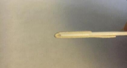
• Wipe connector areas to be cleaned, sliding pad from bottom of pad across and forward to tip of swab, from 1 side to the other, turn over and use long side to dry in same movement.
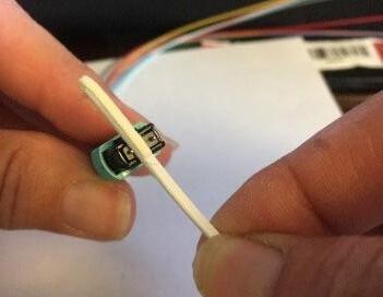
Engineering Standards and Technology Inspect then Connect Cleaning Instructions
• Use the hole on end of pad to clean one alignment pin, then press the end of the swab into the other pin to clean.
• Check your work with a fiber scope. This can take several attempts to get the endface clean.
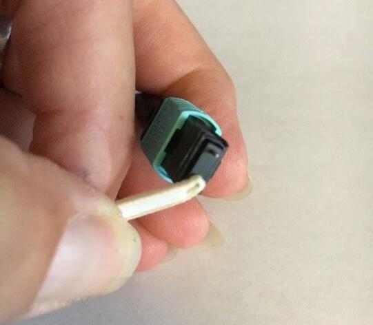

Connector (without pins)
• Cleaned like a single fiber connector, using a cleaning platform. The receptacles will be cleaned as long as you are using a combination cleaning process as recommended.
• Again, using a platen, moisten the platen with cleaning solvent on one end to accommodate 3 swipes of the MPO female endface.

• Holding the connector (If APC, slightly at an angle to accommodate for 8° angle) swiping with medium pressure, from the wet area into the dry area 3 times, without wiping over previous area.
• Inspect, and if clean, make the connection. If NOT, repeat above steps until clean or if determined that the end face is damaged (based on standards of 5 cleanings per connection), replace.

Female
Engineering Standards and Technology Inspect then Connect Cleaning Instructions
Cleaning Using a Probe-Style Cleaning Tool
• The probe style cleaning tools are capable of cleaning a connector end face separately or through the adapter.
• Slightly engage probe by pulling back but do not allow to click. Lightly “spot” a QbE-2 wipe on the platen with Electro-Wash PX Fiber Optic Cleaner, this will help alleviate “over saturation” of the material.
• Lightly touch the tip of probe and release.
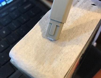
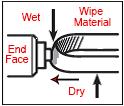
• Insert connector or insert probe though adapter and click 2-3 times to move past the wet area and allow material to dry wipe.
•

• Inspect connector, repeat if necessary (following standards)
• If cleaning a male connector, clean the pins (see above)
Engineering Standards and Technology
MSO Applications - Panels and Splitter Scenarios
LGX 14 Slot Chassis
144 Panels Patch and Splice or Patch Only
Engineering Standards and Technology
Grounding Recommendations
Panels
Patch only panels with an IFC cable, containing no metallic materials, does not need the cable grounded at the panel.
If the panel itself needs to be grounded, scrape some paint from the panel and the frame at the point of contact where a ground wire running from the frame to the panel makes contact. If an isolation kit was used when the frame was mounted to the floor, the frame will need a ground wire from the frame to a common ground. NOTE: If bonding/grounding is needed for the FxMP panel, a threaded screw hole is available to address this need.
Patch and splice panels with an OSP armored cable, where the metallic armoring (shield) is entering from the exterior of the building to the panel, will need to be grounded at the panel.
After the shielding has been removed back to the green cable clamp used for mounting the cable to the panel, install a shield bonding clamp to the metallic shield. Then, connect a ground wire from the bonding clamp to the appropriate building ground.
No metallic material should make contact with the panel when not grounding to the frame.
Cabinets
Patch only cabinets, with a non-armored cable being spliced outside the cabinet, the cabinet will need to be the only thing grounded.
Using the ground bar mounted in the cabinet, install a ground wire from the ground bar to a ground rod. The ground rod will also be used to ground any metallic armored (shielded) cable that will be spliced to the terminated cable coming from the cabinet.
Patch and splice cabinet, with an OSP armored cable where the metallic armoring (shield) is continuous entering into the cabinet will need to be grounded to the cabinet ground bar.
After the shielding has been removed from the cable entering the cabinet back to the liquid tight strain relief fitting, attach a shield bond to the metallic shield and install a ground wire from the bond to the cabinet ground bar. The ground bar will need to be installed with a ground wire connecting the ground bar to the ground rod.
Patch and splice cabinet with ground box will be grounded the same as the path and splice cabinet, with an additional ground wire being installed from the cabinet ground bar to the ground box ground bar.
Wall Boxes
Exterior and interior wall boxes can be grounded using the wall box ground lug.
A ground wire will need to be installed from the lug to the appropriate ground; this could be a ground rod, building steel, water pipe or the buildings common ground. If armored cable enters the panel, it will need to be grounded using the same steps as OSP cabinets.
Clearfield’s ground bonding kit part number is FMA-JZZ.
Engineering Standards and Technology Optical Splitter Product Notes
Optical Splitters are used in PON (Passive Optical Network) architectures.
PON (Passive Optical Networks)
There are two common types of systems that make up fiber networks: Active Optical Networks and Passive Optical Networks. Each offer ways to separate data and route it to multiple locations, and each have advantages and disadvantages as compared to the other. An active optical system uses electrically powered switching equipment, such as routers or switch aggregators, to manage signal distribution and direct signals to specific locations. A passive optical network, on the other hand, does not include electrically powered switching equipment and instead uses optical splitters to separate and collect optical signals as they move through the network. A passive optical network shares fiber optic strands for portions of the network and are then split to feed the signal to multiple locations. Powered equipment is required only at the source and receiving ends of the signal.
A Passive Optical Network (PON) is a point-to-multi-point fiber to the premise network architecture. This type of network uses unpowered Optical Splitters along with WDM/CWDM/DWDM to enable a single optical fiber to be split into many separate fibers to serve multiple locations. A PON consists of an optical line terminal (OLT) at the service provider’s central office and optical network units (ONUs) near or at the end users location. A PON reduces the amount of fibers and central office equipment required in the network, especially when compared to typical point-to-point architecture. A passive optical network is one form of a fiber-optic access network.
Passive optical networks or PONs have some distinct advantages. They are efficient in that each fiber optic strand can be split many times and can serve many users. The majority of the existing networks are splitting the signal 32 times, while newer systems have gone even further by splitting 64 times. There are even some networks pushing the envelope even further by splitting a signal 128 times. PONs have a low building cost relative to active optical networks along with lower maintenance costs. Because there are few moving or electrical parts, there’s simply less that can go wrong in a PON.
Splitters play an important role in Fiber to the Home (FTTH) networks by allowing a single PON network interface to be shared among many subscribers. They are the network element that put the passive in Passive Optical Network. In some cases, FTTH systems may combine elements of both passive and active architectures to form a hybrid system.
Technologies used to fabricate splitters and couplers.
Planar Lightwave Circuit (PLC or Planar)
PLC splitters are used to separate or combine optical signals. A PLC is a micro-optical component based on planar lightwave circuit technology and provides a low cost light distribution solution with small form factor and high reliability. PLCs are manufactured using silica glass waveguide circuits that are aligned with a V-groove fiber array chip that uses ribbon fiber. Once everything is aligned and bonded, it is then packaged inside a miniature housing. PLC Splitters have high quality performance, such as low insertion loss, low PDL, high return loss and excellent uniformity over a wide wavelength range from 1,260 nm to 1,620 nm and have an operating temperature -40ºC to 85ºC. Clearfield ® products meet or exceed Telcordia GR-1209 and GR-1221 certifications.
FBT Splitter Specifications
FBT is the traditional technology in which two fibers are placed closely together, typically twisted around each other and fused together by applying heat while the assembly is being elongated and tapered. A signal source controls the desired coupling ratio. The fused fibers are protected by a glass substrate and then protected by a stainless steel tube, typically 3 mm diameter by 54 mm long. As this technology has developed over time, the quality of FBT splitters has improved and they can be deployed in a cost-effective manner. FBT splitters are widely accepted and used in passive optical networks, especially for instances where the split configuration is not more than 1x4. The slight drawback of this technology is when larger split configurations such as 1x16, 1x32 and 1x64 are needed. FBT technology is limited to the number of splits that can be achieved with one coupling. If more than four splits are required, multiple FBT splitters can be spliced together in concatenation to multiply the amount of splits available. This is also known as a tree splitter or coupler. When using this design, the package size increases due to multiple FBT splitters and splices needed to concatenate. The insertion loss also increases with the additional splitters and splices used. When high split counts are needed and small package size and low insertion loss is critical, a PLC splitter is more ideal.
Engineering Standards and Technology
Optical Splitter Product Notes
Planar Lightwave Circuit (PLC) Optical Splitter Specifications
Fused Biconic Taper (FBT) Dual Window - Wavelength Flattened (Terminated Specifications)
Engineering Standards and Technology WDM Product Notes
In the field of fiber-optics, WDM stands for Wavelength Division Multiplexing. This is a technology which combines many optical signals onto one fiber by using different light wavelengths (i.e. colors) of laser light. This technique also enables bi-directional communications over one strand of fiber, as well as multiplying the capacity of fibers used in fiber optic networks. The concept was first published in 1970. By 1978, WDM systems were being tested in the laboratory. Most WDM systems operate on single mode fiber optic cables. Some forms of WDMs are made to work with multimode fiber cables.
WDMs combine or multiplex (Mux) more than one wavelength onto one fiber. This is done by a discrete device, using fiber pigtail collimators and wavelength/light filters that are aligned and mounted in a glass sub-straight and typically packaged in a stainless steel tube for increased protection. The optical filtering devices used are typically solid-state, single-frequency Fabry–Pérot interferometers in the form of thin-filmcoated optical glass filters. The wavelength/light filters only allow specific wavelengths of light to pass through the filter and the remainder of the wavelengths to be reflected back. WDMs can also be used to separate or demultiplex (demux) more than one signal using the same device and transmitting the signal in the opposite direction. Wideband WDMs typically are 1,310 nm and 1,550 nm devices with an operating window of ± 50 nm of each specific wavelength. The 1,310 nm port will have an actual operating wavelength window of 1,270 nm to 1,360 nm. The 1,550 nm port will have an operating wavelength window of 1,500 nm to 1,600 nm.
Fiber Optic WDMs are used to increase the amount of information that can be transmitted over a single fiber. A typical two channel WDM will be used to multiplex (Mux) two different wavelengths onto one fiber. This allows you to simultaneously transmit two different networks/ systems over the same fiber. If you are using a WDM multiplexer at the beginning of your network, you will most likely need to use a WDM Demultiplexer (Demux) at the opposite end to separate (or demultiplex) the wavelengths to allow them to be directed to the correct receivers. Using a simple two wavelength WDM can increase the service capacity by two times for the same number of fibers. If you are currently using four fibers, you will be able to double your capacity and free up fibers for other use.
Today’s WDM systems can handle as many as 160 signals and can transmit a basic 10 Gbit/s system on a single fiber, to over 1.6 Tbit/s on a single fiber. This is achieved by using Course Wave Division Multiplexing (CWDM) and Dense Wave Division Multiplexing (DWDM) - other forms of WDMs. Course Wave Division Multiplexing (CWDM) works very similarly to the WDMs mentioned earlier, however CWDMs offer more channels using wavelength/channel spacing of 20 nm with a working passband of ± 6.5 nm from the wavelength’s center. This allows you to add multiple wavelengths onto one fiber and gives us the ability to use 2, 4 or 8 channels and even up to 16 or 18 channels, depending on the actual classification of the glass fiber being used. In 2002, the ITU standardized a channel spacing grid for use with CWDM (ITU-T G.694.2), using the wavelengths from 1,270 nm through 1,610 nm with a channel spacing of 20 nm. (G.694.2 was revised in 2003 to shift the actual channel centers by 1, so that strictly speaking, the center wavelengths are 1,271 to 1,611 nm, but are still typically referred to by 1,270 nm to 1,610 nm). Depending on the optical glass fiber used, many CWDM wavelengths below 1,470 nm are considered “unusable” on older G.652 specification fibers, due to the increased attenuation in the high water peak band of 1,360 nm to 1,460 nm. Improved fibers which conform to the G.652.C and G.652.D standards nearly eliminate the “water peak” attenuation and allow for full operation of all 18 ITU CWDM channels. CWDM is popular with the Cable TV networks, where different wavelengths are used for the downstream and upstream signals. In these networks, the wavelengths used are often widely separated. For example, the downstream signal might be in the 1,470 nm to 1,610 nm range, while the upstream signal is typically the 1,310 nm wavelength.
Dense Wavelength Division Multiplexing (DWDM) takes the WDM and CWDM one step further by narrowing the channel spacing in the C and L Band range. DWDM signals within the ITU C Band, are wavelengths between 1,530 nm and 1,565 nm (C band) and 1,570 nm to 1,625 nm (L band) adhering to the DWDM ITU-T G.694.1 frequency grid. DWDMs allow you to increase your wavelength capacity even further by offering more channels in these bands. DWDM offers multiplexing of multiple channels using 200 GHz, 100 GHz and 50 GHz spacing with the option to have an added Expansion port and/or Monitor port. Some technologies are capable of 12.5 GHz spacing (sometimes called ultra dense WDM). Such spacing is only achieved by free-space optics technology. New amplification options enable the extension of the usable wavelengths to the L-band, more or less doubling the number of channels. Early DWDM systems contained 4 or 8 wavelength converting transponders in the mid 1990s. By the year 2000, commercial systems capable of carrying 128 signals were introduced. There have been even more advancements in DWDM technology where they are starting to test over 1,000 channels, but this is in its early developmental stages and is not yet ready for commercial use.
WDM systems are popular with Telecommunication, Cable TV and Internet providers because they allow them to expand the capacity of the network without laying more fiber. By using WDM technology and optical amplifiers, they can accommodate several generations of technology in their optical infrastructure without having to overhaul the fiber optic backbone network. Capacity of any fiber network can be multiplied simply by upgrading to WDM, CWDM or DWDM technology.
WDM, CWDM and DWDM are all based on the same concept of adding multiple wavelengths of light onto a single fiber, but differ in their spacing of wavelengths, number of channels and the ability to amplify the multiplexed signals. EDFAs provide an efficient means of amplification for the DWDM wavelengths. However, CWDM optical amplification is not available, limiting the CWDM optical spans to several tens of kilometer.
Engineering Standards and Technology Fiber Optic Assemblies
Scope
This Engineering Specification is written to provide a summary of the performance criteria for terminated optical fiber connectors on optical fiber cable. This document will summarize product performance requirements based on the following established criteria: EIA/TIA-455, Fiber Optic Test Procedures (FOTP), and parts of Telcordia GR-326. This document may be revised, without notice, in accordance with standard Clearfield ® document change procedures.
Note: Information in this document is proprietary to Clearfield and shall not be used, copied reproduced or disclosed in whole or in part without prior written permission of Clearfield.
General Product Descriptions
Optical Fiber:
• Singlemode full Spectrum fiber meets ITU-T G.652.D (06/05) specification. Reduced Water Peak (RWP) fibers are considered. Full Spectrum because the reduction of loss in the water absorption spectral region (the E band)
• Singlemode Bending Loss Insensitive optical fiber meets ITU-T G.657 Class A (12/06). Fully compliant with the G.652 singlemode fibers specification
• Multimode 50/125 μm Graded Index Optical Fiber meets ITU-T G.651 (02/98). Multimode 50/125 μm Graded Index Optical Fiber for the optical access network meets ITU-T G.651.1 (07/07)
• Optical fiber cable for the optical access network recommends a quartz multimode fiber to be used for the access network in specific environments
• Color Coding of Fiber Optic Cable must be in accordance with TIA/EIA 598-A
Fiber Optic Jacketing:
• All riser and plenum cables will meet requirements described in TR-NWT-000409. Fiber optic cable for plenum environments shall be NEC type OFNP and listed as UL 910. Fiber optic cable for riser environments shall be listed as NEC type OFNR and listed as UL 1666. Fiber optic cable for outside plant environments shall meet Telcordia GR-20 requirements
Connectors Optical Fiber:
• GR-326: Generic Requirements for Singlemode Optical Connectors and Jumper Assemblies
Performance Requirements
The following specifications refer to terminated optical fiber connectors on optical fiber cable. All measurements performed using standard procedures with a non-contacting interferometer. Insertion Loss and Return Loss figures are measured using a launch cable meeting the criteria specified in WIO 900.
Applicable Documents
The following documents form a part of this specification to the extent defined herein. In the event of a conflict, this document shall govern:
Applicable Documents
GR-326-CORE Generic requirements for singlemode optical connectors and jumper assemblies, Issue 4
EIA/TIA-455
Fiber optic test procedures (FOTP), EIA/TIA
Clearfield ® Drawing #17012 Connector end-face polish geometry, Clearfield ®
Clearfield Drawing #17010
Specification for multimode connector end-face visual inspection criteria
Clearfield Drawing #17011 Specification for multimode connector end-face visual inspection criteria
ITU-T G.652.D (06/05) Characteristics of singlemode optical fiber and cable
ITU-T G.657 Class A (12/2006) Characteristics of a bending loss insensitive singlemode optical fiber and cable for the access network
Engineering Standards and Technology Fiber
Optic Assemblies
Minimum Performance Specifications for Terminated Singlemode Connectors
*MPO/MTP Connector Specifications are for 12 fiber cable assembly connectors
Note: All Clearfield ® fiber optic patch cords are designed and tested to operate between -40°C and 85°C.
Engineering Standards and Technology Fiber Optic Assemblies
Specifications
ferrule
1.0 POLISH RADIUS
radius of curvature center of fiber
The radius of curvature is defined as the radius of the end-face surface as measured from the ferrule axis.
spherical top of polish apex offset
ferrule
3.0 APEX OFFSET

center of fiber
Apex offset is measured as the distance between the spherical center of the polished end-face and the center of the fiber.
center of fiber
ferrule top of fiber top of polish fiber recess
2.0 FIBER UNDERCUT / PROTRUSION
Fiber undercut or protrusion is defined as the distance between the top of the glass fiber as measured against the surrounding material in a spherical plane.
Undercut = -.02R3 + 1.3R2 - 31R + 325.

radius of curvature polish angle center of fiber
ferrule
4.0 ANGLED POLISH
The end face is polished at an angle relative to the axis perpendicular to the ferrule axis.
Engineering Standards and Technology End-Face
What is IL?
Insertion loss (IL) is the loss of signal power resulting from the insertion of a device in a transmission line or optical fiber. Usually expressed as a ratio in dB relative to the transmitted signal power, it can also be referred to as attenuation.
What is RL?
Return loss or reflection loss (RL) is the reflection of signal power resulting from the insertion of a device in a transmission line or optical fiber. It is usually expressed as a ratio in dB relative to the transmitted signal power.
Test and Measurement
Your minimum requirements should include data that meets insertion loss and return loss (reflectance). Insertion loss should meet the 326Core minimum of 0.4 dB, with reflectance meeting 55 dB for UPC connectors and 65 dB for APC. Asking the typical performance measures of a manufacturer’s process can save you on link loss budgets over a long fiber run through a FTTH network.
Apex offset, the measurement for how well the center core of the fiber is centered in relationship to the spherical apex of the polished tip, minimizes lateral offset between two fibers and maintains a better physical contact. Apex offset describes a physical condition of the polished fiber, rather than a performance parameter. It is also an acceptance criteria for Telcordia. An excessive apex offset contributes to high insertion loss and high back reflection readings.
Fiber undercut or protrusion affects the physical contact zone. This metric measures, in nanometers, the height of the fiber under or below the ceramic end-face. Too much undercut minimizes the chance of a good physical contact, while too much protrusion causes excessive fiber deformation when mating occurs resulting in degradation of signal. When two connectors are mated, the ceramic compresses around the fiber core which allows the fibers to squeeze up and make good contact with each other. When they do not touch (because of too much undercut), an air gap is created and loss happens. If the fiber is protruding too far (beyond 50nm), chipping and cracking can occur during the mate.
Radius of curvature is the measurement of the connector end-face spherical condition. The radius generated affects the performance because the radius, when mated with another connector, should be compressing most of the material surrounding the core (ceramic ferrule). A proper radius, 5 to 12 micron, allows for the right compression and max performance. Too tight of a radius will put too much compression on the glass and too loose will put too much on the surrounding ferrule with not enough glass compression. Too much or too little radius can cause light scatter or inadequate physical contact for optimal signal transfer.
Apex offset, fiber undercut/protrusion, and radius of curvature are the main ingredients that work in concert to deliver good IL and RL performance. Processes that drift out of this geometry range can still yield acceptable IL/RL, but sensitive traffic will be affected (such as video) and long term performance of the connector will be compromised.
Your vendor should be able to provide these geometry test reports with on-hand interferometer testing. While you may not require this data for each and every connector, you should require that random testing is being performed to ensure the process is capable and not drifting out of spec. “Garage shops” will not be able to deliver this test data on demand.
Your test reports should account for each connector independently and not a total report that summarizes both ends.
End-face Quality & Cleanliness
Currently, there is not an industry standard for this topic. To be sure, end-face and cleanliness has a direct impact on the performance of the connector.
Several organizations (most notably, NEMI) have studied the impact of end-face defects and cleanliness. The influence of the contamination/ scratches becomes more evident if they are located in the core/cladding areas. Particle contamination can cause a significant increase in IL (up to 10 times) and decrease in RL (up to three times). Scratches applied to the fiber contact zones 1a and 1b, which is an area from the core out to the cladding (125 μm), decreased RL by up to 25%. On the other hand, scratches located in the cladding layer showed little effect on IL and RL. Multiple heavy scratches passing through the core caused severe performance degradation in IL/RL and can be catastrophic.
Connectors with particle contamination will pass on contamination to mated connectors. Contaminant can prevent direct physical contact, creating an air gap. Multiply this by the number of re-mates over time and the problem spreads. Pits and scratches, in the critical contact zone 1a, will collect particulates over time and the same contamination-spread occurs. Long term reliability in dynamic circuits is severely reduced as opposed to those that are static. Scratches and polishing marks outside of critical contact areas are acceptable and do not have any impact on signal performance.
The quality fiber assembly manufacturers and OEMs will have their own inspection criteria. However, these specifications differ from company to company and the differences can cause materials to be “non-conforming” at user/customer sites.
Engineering Standards and Technology
End-Face
Singlemode
Acceptable Fiber End Face
CORE (9 μm shown)
NO DEFECT ZONE (0-25 μm)
Scratches: Fails if there are any scratches at all
Defects: Fails if there are any defects at all
CLADDING (25-115 μm)
Scratches: Fails if any width is more than 3 μm
Defects: Fails if any diameter is more than 5 μm
Fails if there are more than five defects
Exclude if the diameter is less than 2 μm
EPOXY RING (115-135 μm)
CONTACT ZONE (135-250 μm)
Defects: Fails if any diameter is more than 10 μm
Multimode
Notes:
1. Fiber Core: 9 μm diameter
2. End face viewed at a minimum of 400x magnification
3. No visible contamination
Acceptable Fiber End Face
CORE (0-65 μm shown)
Scratches: Fails if any width is more than 3 μm
Defects: Fails if any diameter is more than 5 μm
Fails if there are more than four defects
CLADDING (65-115 μm)
Scratches: No limit ≤ 5 μm
None > 5 μm
Defects: No limit < 5 μm
5 from 5 μm to 10 μm
None > 10 μm
EPOXY RING (115-135 μm)
CONTACT ZONE (135-250 μm)
Scratches: No limit
Defects: No limit < 20 μm
5 from 20 μm to 30 μm
None > 30 μm
Notes:
1. Fiber Core: 50 μm or 62.5 μm
2. End face viewed at a minimum of 400x magnification
3. No visible contamination