
CHAPTER 1. Basic Principles
1.1. Classify each of the following flows as steady or unsteady from the viewpoint of the observer:
Flow Observer
(a) Flow of river around bridge piers
(b) Movement of flood surge downstream
Solution.
(1) Standing on bridge
(2) In boat, drifting
(1) Standing on bank
(2) Moving with surge
(a) Over relatively short time intervals, the observer standing on the bridge will see a steady flow even though the flow may be unsteady over longer time intervals; however, the observer drifting in the boat will see an unsteady flow as the boat passes under the bridge because the velocity increases around the bridge piers even if the approach flow is steady.
(
b) An observer standing on the river bank will see an unsteady flow as the surge passes but a steady flow while riding on the surge if the flow is uniform in the direction of movement.
1.2. At the crest of an ogee spillway as shown in Figure 1.1c, would you expect the pressure on the face of the spillway to be greater than, less than, or equal to the hydrostatic value? Explain your answer.
Solution.
The convex curvature near the crest of the spillway results in a centripetal acceleration toward the center of curvature and a corresponding pressure gradient with decreasing pressure toward the center of curvature. The decreasing pressure reduces the equivalent hydrostatic pressure for a parallel flow so that the pressure is less than hydrostatic on the face of the spillway. The decrease in pressure can be so severe that vapor pressure is reached and cavitation occurs with pitting and erosion of the concrete spillway surface (see Chapter 6).
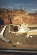
1.3 On the Internet, find a photograph of the Hoover Dam overflow spillway near Las Vegas, Nevada. The flow coming over the spillway is collected in a channel that runs perpendicular to the incoming flow. How would you classify the flow in the collection channel during a flood flow? Explain your answer.
Solution.
Arrows show the flow that would come over the spillway into a collection channel and then flow into a tunnel. The flow in the collection channel during a flood is unsteady and nonuniform but more specifically is unsteady, spatially-varied flow because the discharge is changing in the flow direction.
1.4. The river flow at an upstream gauging station is measured to be 1500 m3/s, and at another gauging station 3 km downstream, the discharge is measured to be 750 m3/s at the same instant of time. If the river channel is uniform with a width of 300 m, estimate the rate of change in the water surface elevation in meters per hour. Is it rising or falling?
Solution.
Use Equation 1.6, the continuity equation:
1.5. A paved parking lot section has a uniform slope over a length of 100 m (in the flow direction) from the point of a drainage area divide to the inlet grate, which extends across the lot width of 30 m. Rainfall is occurring at a uniform intensity of 10 cm/hr. If the detention storage on the paved section is increasing at the rate of 60 m3/hr, what is the runoff rate into the inlet grate?
Solution.
Utilize the continuity equation for a finite control volume given by Equation 1.3 for an incompressible fluid so that the fluid density ρ cancels on both sides of the equation. Then we have
1.6. If the lake level upstream of the spillway in Figure 1.1c is 55 m above the channel floor at the base of the spillway just upstream of the hydraulic jump, estimate the depth and velocity there for a flow rate of 1,000 m3/s and a spillway width of 30 m. What is the value of the Froude number? Neglect the approach velocity in the lake and the head losses on the spillway.
Solution.
Writing the energy equation from the water surface upstream of the spillway where the velocity head is negligible to the floor of the stilling basin downstream of the spillway, and neglecting head losses, we have
Solving by trial and error for the supercritical solution (see Chapter 2), the result is y2 = 1.024 m and
= 33.33/1.024 = 32.55 m/s. The Froude number becomes
which is supercritical and will provide a strong, stable hydraulic jump as shown in Chapter 3.
1.7. A rectangular channel 6 m wide with a depth of flow of 3 m has a mean velocity of 1.5 m/s. The channel undergoes a smooth, gradual contraction to a width of 4.5 m.
(
a) Calculate the depth and velocity in the contracted section.
(
b) Calculate the net fluid force on the walls and floor of the contraction in the flow direction. In each case, identify any assumptions that you make.
Solution.
(a) Apply the energy equation from the approach section 1 to the contracted section 2 with negligible head losses and assuming a horizontal channel bottom:
Substituting and solving, we have from which y
by trial and error and
. Note that there are two solutions, but this is the subcritical solution and the correct one as discussed in more detail in Chapter 2.
(b) Apply the momentum equation in the flow direction in which F = the resultant force of the walls and floor on the flow. Assume a hydrostatic pressure distribution at sections 1 and 2. Because the transition is horizontal, there is no component of the gravity force in the flow direction. The momentum equation becomes
from which F = 63.8 kN
1.8. A bridge has cylindrical piers 1 m in diameter and spaced 15 m apart. Downstream of the bridge where the flow disturbance from the piers is no longer present, the flow depth is 2.9 m and the mean velocity is 2.5 m/s.
(a) Calculate the depth of flow upstream of the bridge assuming that the pier coefficient of drag is 1.2.
(b) Determine the head loss caused by the piers. Solution.
In part (a), apply the momentum equation with the control volume boundaries halfway between the piers; then apply the energy equation in part (b).
(a) The momentum equation, neglecting boundary friction, is
in which D = drag force on the pier; Fp = hydrostatic force; Af = frontal area of the pier at section 1 on a plane perpendicular to the flow direction = ay1; a = pier diameter = 1.0 m; s = pier spacing = 15.0 m; CD = drag coefficient =1.2; and Q = A2V2 = (15)(2.9)(2.5) = 108.8 m3/s . Using continuity and substituting, we have
which reduces to and the solution is y1 = 2.932 m, or a backwater of 0.032 m, and V1 = Q/A1 = 108.8/[(15)(2.932)] = 2.474 m/s.
(b) The head loss, hL, is obtained from the energy equation assuming a negligible change in channel bed elevation from point 1 to 2:
1.9. A symmetric compound channel in overbank flow has a main channel with a bottom width of 30 m, side slopes of 1:1, and a flow depth of 3 m. The floodplains on either side of the main channel are both 300 m wide and flowing at a depth of 0.5 m. The mean velocity in the main channel is 1.5 m/s, while the floodplain flow has a mean velocity of 0.3 m/s. Assuming that the velocity variation within the main channel and the floodplain subsections is much smaller than the change in mean velocities between subsections, find the value of the kinetic energy correction coefficient
Solution.
Flow area of the floodplains, Af :
Flow area of the main channel, Am:
Then for the entire channel, we have a total discharge, Q = 300(0.3 m/s) + 98.75(1.5 m/s) = 238 m3/s, and mean velocity V = Q/A = 238/398.75 = 0.597 m/s. The kinetic energy flux correction coefficient, α, then is given by
1.10. The power law velocity distribution for fully-rough turbulent flow in an open channel is given by in which u = point velocity at a distance z from the bed; u* = shear velocity = (τ 0/ρ)1/2; τ 0 = bed shear stress; ρ = fluid density; ks = equivalent sand grain roughness height; and a = constant.
(a) Find the ratio of the maximum velocity, which occurs at the free surface where z = the depth, y0, to the mean velocity for a very wide channel.
(b) Calculate the values of the kinetic energy correction coefficient α and the momentum flux correction coefficient βfor a very wide channel.
Solution.
(a) Substituting for u = u max at z = y0, we have
The mean velocity, V, is obtained by integration of the point velocity distribution over the depth for a very wide channel:
Then by comparison, it is obvious that umax/V = 7/6
(b) From the definition of α for a very wide channel, we have
Similarly, βis given by
1.11 The velocity distribution for laminar flow in an open channel is given by
in which ν = kinematic viscosity; y0 = depth of flow; and the other variables are as defined in Exercise 1.10. Answer questions (a) and (b) of Exercise 1.10 for this laminar velocity distribution.
Solution.
(a) Substituting for u = u max at z = y0, we have
The mean velocity, V, is obtained by integration of the point velocity distribution over the depth for a very wide channel:
Then by comparison, it is obvious that umax/V = 3/2.
(b) From the definition of α for a very wide channel, we have Similarly, βis given by
1.12. An alternative expression for the velocity distribution in fully-rough, turbulent flow is given by the logarithmic distribution
in which κ = the von Karman constant = 0.40; z0 = ks / 30; and the other variables are the same as defined in Exercise 1.10. Show that α and βfor this distribution in a very wide channel are given by
in
Solution.
First, find the mean velocity, V, by integrating over the depth with a change of variable, η
so that dz = z0 dη and the upper limit, η0 = y0/z0. Then we have
so, the mean velocity is and the maximum velocity is given by
so we conclude that
Now we can calculate α from its definition, using the same change of variable to η, to produce
From a math handbook, we can look up the integral, which is given by
Substituting the integral, with the limits applied, and the expression for mean velocity into the equation for α, we have
in which x = ln η0 = 1/ε + 1. Substituting for x in terms of ε, we have finally Similarly, we have for β and the indefinite integral is given in this case by so that upon substitution into the equation for βwe have
in which x = ln η0 = 1/ε +1 as before.
1.13. In a hydraulic jump in a rectangular channel of width b, the depth after the jump y2 is known to depend on the following variables:
in which y1 = depth before the jump; q = discharge per unit width = Q/b; and g = gravitational acceleration. Complete the dimensional analysis of the problem.
Solution.
We have n = 4 variables but only two fundamental dimensions, L and T, so that m = 2 and n–m = 2 Π groups. Choose y1 and g as repeating variables. Then by inspection, the first Π group is given by
The second Π group is found from in which the square brackets denote "the dimensions of" the enclosed variables. Equating exponents on length, L, and time, T, we have from which d = –1/2 and c = –3/2 so that
which is the Froude number for a rectangular channel. Finally we can write from the dimensional analysis that
1.14. The backwater ∆y caused by bridge piers in a bridge opening is thought to depend on the pier diameter and spacing, d and s, respectively; downstream depth, y0; downstream velocity, V; fluid density, ρ; fluid viscosity, µ; and gravitational acceleration, g. Complete the dimensional analysis of the problem.
Solution. First, write the functional relationship as
We have 8 variables and 3 fundamental dimensions so there must be 5 Π groups. Choose ρ, V, and y0 as repeating variables. Then by inspection, the first 3 Π groups are Π1 = ∆y/y0; Π2 = d/y0; and Π3 = s/y0. The next Π group is found from
in which the square brackets denote "the dimensions of" the enclosed variables. Equating exponents, we have
from which c = –1; d = –1; and e = –1. Then Π4 = ρVy0/µ, which is the Reynolds number of the flow. The final Π group is obtained from
Equating the exponents, we have
so that c = 0; d = –2; and e = 1. Then Π5 can be written as V/(gy0)1/2, which is the Froude number. The final functional relationship, with some rearrangement of the Π groups, is
1.15. The longitudinal velocity u near the fixed bed of an open channel depends on the distance from the bed, z; the kinematic viscosity, ν; and the shear velocity u* = (τ 0/ρ)0.5 in which τ 0 is the wall shear stress. Develop the dimensional analysis for the point velocity, u.
Solution.
The functional relationship is
There are 4 variables and only 2 fundamental dimensions (L and T), so we should expect 2 Π groups. Choose z and u* as repeating variables. Then we have which, by inspection, gives Π1 = u/u*. The second Π group comes from
from which d = –1 and c = –1 so that Π2 = u*z/ν. The final relationship is
1.l6. In very slow motion of a fluid around a sphere, the drag force on the sphere, D, depends on the sphere diameter, d; the velocity of the approach flow, V; and the fluid viscosity, µ. Complete the dimensional analysis. How many dimensionless groups are there and what are the implications for the corresponding values of the group(s)? Why was the fluid density not included in the list of variables?
Solution.
The functional relationship is
There are 4 variables and 3 fundamental dimensions, so we should expect only one Π group. Choose d, V, and µ as repeating variables, which do not themselves form a Π group. Then we have
from which c = –1; b = –1; a = –1 and Π1 = D/µVd. In this case, according to the Buckingham Π theorem, we can set a function of the single Π group to zero, which can only be true if the Π group itself is a constant. This constant was determined analytically by Stokes to be 3π, but in the general case it could be determined experimentally. The fluid density was not included in the list of variables because the acceleration terms were neglected as a result of the condition of very slow, or creeping, motion.
1.17. The discharge over a sharp-crested weir, Q, is a function of the head on the weir crest, H; the crest length, L; the height of the crest, P; density, ρ; viscosity, µ; surface tension, σ ; and gravitational acceleration, g. Carry out the dimensional analysis using ρ, g, and H as repeating variables. If it is known that Q is directly proportional to crest length, L, how would you alter the dependent Π group?
Solution.
Write the functional relationship as in which there are 8 variables and 3 fundamental dimensions resulting in 5 Π groups. Use ρ, g, and H as repeating variables as suggested. Then each Π group is determined as follows:
from which a =0; b = –1/2; and c = –5/2 so that Π5 = Q/(g 1/2H 5/2 ). The final functional relationship can be written as
If it is known that Q varies directly with the crest length, L, then the dependent Π group can be multiplied by (H/L) with the result
The function φ becomes a discharge coefficient that depends on the Π groups listed, and the form of its functional dependence can be determined by experiment. See Chapter 2.
1.18. The terminal fall velocity, wf, of a sphere in a stationary fluid of infinite extent is a function of the fluid density, ρ ; the reduced gravitational acceleration, (ρs/ρ 1)g, in which ρs = density of the sphere and g = gravitational acceleration; the dynamic fluid viscosity, µ ; and the sphere diameter, d. Complete the dimensional analysis for the fall velocity as the dependent variable with ρ, d, and µ as repeating variables. Repeat the dimensional analysis with (ρs/ρ 1) and g taken as separate independent variables.
Solution.
Write the functional relationship as
in which there are 5 variables and 3 fundamental dimensions resulting in 2 Π groups. Use ρ, d, and µ as repeating variables as suggested. Then each Π group is determined as follows:
Then we have for the first Π group:
from
For the second Π group:
from which a = 2; b = 3; and c = –2 so that Π
given by
In this case, knowledge that the submerged weight of the particle is the important gravitational force results in the final two dimensionless numbers that appear in the relationship for fall velocity derived in Chapter 10. If (ρs/ρ 1) and g are taken as separate independent variables, then the result is not quite as insightful and is given by