Robotized painting with automatic reconfiguration

Page 1

ARTIGO TÉCNICO Marcos Ferreira, Paulo Malheiros, A. Paulo Moreira, Norberto Pires

ROBOTIZED PAINTING WITH AUTOMATIC RECONFIGURATION ABSTRACT Industrial manipulators are widely used on production lines due to its highly accurate movements, In this paper, a case study of an adaptive robotized painting system for small production series is presented. The concept is based on contactless technology, using artificial vision and laser scanning, to identify and characterize different objects traveling on a conveyor. The collected data enables automatic system reconfigurations according to the specific profile of each object. A robotic manipulator executes the painting process after its base algorithms have been adapted online, and the system becomes fully autonomous and capable of dealing with small production series without human intervention for reprogramming and adjustments. Described methodology can be applied to numerous applications, other than painting and object recognition.

I. INTRODUCTION A. Motivation Production lines tend to evolve into the concept of mass customization, i.e., working on small series with adapted and specialized procedures to each of them according to costumer specific needs. High versatility is mandatory in these systems and robotized cells demand additional efforts to be integrated in such systems: industrial manipulators still take a long time to reconfigure. Programming is truly time consuming and usually require experienced and highly qualified workers. Overall not compatible with flexible setups neither with companies budgets since both qualified programmers and reconfigurations associated downtime imply strong financial efforts. Despite these, manipulators are strongly desired at production lines due to a series of advantages over human work, e.g., the ability to work continuously, high accuracy and repeatability, immunity to fatigue, distractions and even hazardous environments. Taking the case study of an industrial painting system working on small production series, a flexible architecture is presented that enables fast system reconfigurations and adaptive behavior without human intervention.

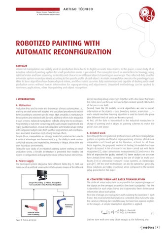
B. Power supply The developed system integrates three different fields (Fig.1). First, we make use of an artificial vision system that captures images of the different

pieces traveling along a conveyor. Together with a line-laser that scans the entire pieces as they are transported (at constant speed), 3D models of the pieces are built. HZXdcY! [gdb i]Z (9 bdYZah! hZkZgVa Va\dg^i]bh VgZ gjc id ZmigVXi information on the objects — size, boundary, texture, orientation . . . — and a simple machine learning algorithm is used to classify the piece (the different kinds of parts are known a priori). At last, all the data is transmitted to the industrial manipulator in charge of painting and it adapts its painting schemes to match the piece’s size and layout.

C. Related work Even though the integration of artificial vision with laser triangulation, pattern recognition and flexible reprogramming schemes of industrial manipulators isn’t found yet in the literature, at least for all these fields together, the proposed method of finding 3D models has been largely discussed. A lot of research has been carried out with facial recognition [7], object dimensions measurements [8] and even in the [^ZaY d[ ^cheZXi^dc [dg fjVa^in Xdcigda P.R# HdbZ VcVanh^h dc egZX^h^dc have already been made, comparing the use of single or multi laser beams [10] or alternative computer vision systems, as stereoscopic pairs [11]. Off-the-shelf technologies can also be option but, generally, these solutions are highly expensive when compared to the custom setup presented in this paper.

II. COMPUTER VISION AND LASER TRIANGULATION The artificial vision subsystem is responsible for capturing images of the objects on the conveyor, on which a line-laser is projected. This line is identified in each video frame and it generates three dimensional information about each piece. First line of image processing starts with isolating the laser line in each frame: the environment illumination is controlled (this makes the area the camera is filming dark) and this way the laser line appears brighter in the images. A simple binarization algorithm is applied

(1) Figure 1 HnhiZb VgX]^iZXijgZ

and we now work over very clean images as the following one: robótica

[3 ]


ARTIGO TÉCNICO

The recognition of the shapes was carried out using a knearest neighbor classifier [6]. First we define N features that we must be able to extract from the 3D models. We then define a N-dimensional space, each direction corresponding to one feature. We take some pieces to paint and use them as training data, i.e., we compute the N features and them classify them manually. When running, upon detecting a new piece in the conveyor, the model is created, the features are extracted and them the distance ( within the feature space) to each one of the training points is computed. Choosing the k nearest points, the new piece will be attributed the most common class among the k neighbors. To recognize the plates, we defined the following features: į2m Horiz į2m Vert both of which representing the variance of depth in M slices of the 3D models, i.e., we pick three dimensional representations and slice it both horizontally and vertically as Fig. 11 suggests.

Figure 12 LdgaY gZ[ZgZci^Va DMlNlOl VcY gdiViZY [gVbZ DMdW _NdW _OdW _ i]Vi ^h Va^\cZY l^i] i]Z e^ZXZ

Hd! cdl! i]Z l]daZ egd\gVb l^aa WZ ZmZXjiZY VXXdgY^c\ id V gdiViZY [gVbZ that is completely described by the plane that was computed before, when analysing the 3D models.

V. CONCLUSIONS AND FUTURE WORKS A. Conclusions An adaptive scheme for an industrial painting process of small series was developed. Computer vision together with laser triangulation techniques allowed the building of accurate 3D models of objects; this subsystem may get to be useful in many other application areas,e.g., quality inspection setups. Using the 3D model, features are extracted and a classification algorithm was implemented, that enables distinguishing between different pieces. The robotized painting cell is automatically reprogrammed using the information extracted, adapting the painting movements to the objects size and orientation.

Figure 11 =dg^odciVa aZ[i VcY kZgi^XVa g^\]i Xjih dc i]Z (9 bdYZa h]dlc ^c ;^\# ,

Therefore, each į2m stands for the mean of the variance on depth in those cuts, which themselves are built up from Nc points, so į2m is defined as:

(15)

B. Future Works A more robust and accurate camera calibration method should be implemented for enhanced precision on scanning and, consequently, on 3D reconstructions. Classification algorithm needs further validation and test since just a few pieces were available for this work (no more then 2 of each kind).

VI. ACKNOWLEDGMENTS Marcos Ferreira and Paulo Malheiros acknowledge FCT for their PhD grants.

It can easily be seen that, for smooth surfaces, both į2mHoriz and į2mVert take small values. On the other hand, a undulated surface presents high depth variance according to the direction the “waves” have, i.e., an horizontal wavy profile will have high į2mHoriz and low į2mVert , and vice-versa when thinking about the vertical wavy surface. For a more generic application, where there are no obvious distinction of objects with such a few features, more complex and robust algorithms other then k-nearest neighbors may be applied, such as neural networks or support vector machines, requiring the extraction of a greater number of features perhaps, but since we have the accurate 3D model, basis are laid so that this task can be fairly easily accomplished. Even for this application, should the need arise to distinguish more shapes, we may still maintain the used method and extract some more rich features, so this solution comes to be quite modular, flexible and expansible. 7Z[dgZ ^c^i^Va^o^c\ i]Z eV^ci^c\ egdXZhh! lZ jhZ i]Z dW_ZXi Y^bZch^dch hd that the program can adapt itself to the piece. This is accomplished simply by writing the values into the robot’s controller, from where the developed painting programs will read the piece dimensions. At last, another important step is to take advantage of knowing the piece inclination on the conveyor. Default programs assume the objects stand vertically; we then change the coordinate referential of the program to one that best fits the piece slop (as shown in Fig. 12).

REFERENCES [1] Mark Nixon and Alberto Aguado, Feature Extraction and Image Processing , Elsevier, 2nd Edition, 2008. P'R <# <# HVk^^! Æ8VbZgV 8Va^WgVi^dc 8dbedjcY <ZcZi^X H^beaZm 6a\dg^i]bÇ! in Journal of Optoelectronics and Advanced Materials, Vol. 6, No. 4, p. 1255 - 1261, 2004. [3] Juyang Weng, Paul Cohen, and Marc Herniou,“Camera Calibration with Distortion Models and

[4]

Accuracy Evaluation”, IEEE Transactions on Pattern Analysis and Machine Intelligence, Vol. 14, No. 10, 1992. David Eberly,“Least Squares Fitting of Data”, Geometric Tools LLC, 2008.

P*R >bV\^c\HdjgXZ! 9B@ (&7J%( XVbZgV YViVh]ZZi! VkV^aVWaZ dc ]iie/$$lll#i]Z^bV\^c\hdjgXZ# Xdb$ZcTJH$ egdYjXih$XVbZgVh$jhW"XXY"bdcd$Yb`(&Wj%($# [6] [7]

T. M. Cover and P. E. Hart, “Nearest Neighbor Pattern Classification”, IEEE Transaction on Information Theory , 13: 21-27 , 1967 David Acosta, Olmer Garca and Jorge Aponte ,“Laser Triangulation for shape acquisition in a 3D

HXVccZg Eajh HXVccZgÇ! Proceedings of the Electronics, Robotics and Automotive Mechanics Conference (CERMA’06) , 2006 P-R B^X]Va 9ZbZnZgZ! 9d Gjg^bjcoj VcY 8]g^hi^Vc :j\cZ ! Æ9^VbZiZg BZVhjgZbZci d[ He]Zg^XVa Objects by Laser Triangulation in an Ambulatory Context”,IEEE Transactions on Instrumentation and Measurement, Vol. 56, NO. 3 , JUNE 2007 P.R GZ^c]VgY Cda^ VcY B^X]VZa @gVj]VjhZc ! ÆBjai^"WZVb aVhZg ig^Vc\jaVi^dc [dg i]Z bZVhjgZbZci of geometric features of moving objects in production lines”, IEEE 2003. P&%R LVc\ AZ^! 7d BZ^ ! <Vd ?jc VcY Dj 8]jcH]Zc\ ! Æ6 CdkZa 9djWaZ Ig^Vc\jaVi^dc (9 8VbZgV Design”, Proceedings of the 2006 IEEE International Conference on Information Acquisition, Weihai, Shandong, China August 20 - 23, 2006 P&&R M^Vc\n^c BV VcY =dc\W^c !Æ=nWg^Y HXZcZ GZXdchigjXi^dc Wn >ciZ\gVi^c\ HXVc 9ViV VcY HiZgZd Image Pairs”, Sixth International Conference on 3-D Digital Imaging and Modeling, 2007

robótica

[7 ]


Issuu converts static files into: digital portfolios, online yearbooks, online catalogs, digital photo albums and more. Sign up and create your flipbook.