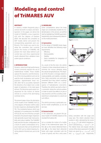
Bruno M. Ferreira, Aníbal C. Matos, Nuno A. Cruz INESC TEC (formerly known as INESC Porto), Faculty of Engineering, University of Porto, Rua Dr. Roberto Frias, 378, 4200-465 Porto, Portugal Email: bm.ferreira@fe.up.pt B. Ferreira is supported by the Portuguese Foundation for Science and Technology (FCT) through the PhD grant SFRH/BD/60522/2009.
ARTIGO CIENTÍFICO 10 robótica
Modeling and control of TriMARES AUV ABSTRACT In robotics, models frequently play a central role both in analysis and development. In this paper, we derive the model of TriMARES, a new inspection AUV with five degrees of freedom (DOF). We describe the complete six DOF model, derive and present the corresponding parameters and coefficients. This model was used to develop the controllers that currently govern the motion of TriMARES. We present the main ideas behind such control laws and show experimental results obtained from validation tests under typical conditions.
II. MODELING Some considerations about the body shape can considerably simplify the model derivation. In this section, we will first start by highlighting TriMARES geometric haracteristics and subsequently determine the model parameters.
I. INTRODUCTION Dynamic, robust and high performance control commonly requires the use of mathematical models. Those models capture the dynamics and the kinematics of the moving platform and can be used for both localization and control purposes. Approximated linear models often fail to accurately represent the dynamics of an object over a wide region of operation, in the state space domain. This becomes particularly consequential for the motion of marine vehicles as a result of the dominating nonlinear terms.
As a result of the first item, the vehicle is based on three streamlined bodies to minimize the viscous damping along the natural (longitudinal) axis. The disposal of the thrusters is strongly related to maneuverability and stability considerations. Body assymetries are particularly unwanted since they induce couplings between different DOFs as a consequence of hydrodynamic cross-terms. Therefore, the vehicle was built so that it is symmetric along the vertical xz-plane in order to avoid cross-effects on yaw or sway dynamics and thus avoiding undesired thrust compensation to cancel out such effects.
The present paper shows the derivation of the model of the TriMARES AUV [1], a five degrees of freedom (DOFs) robot for dam inspection, developed by INESC TEC. The modularity feature, which was exploited in its predecessor, the MARES AUV [2], [3], was one of the key concepts that led to the present shape. Inspection tasks generally require high maneuverability and robust stability. The TriMARES’ body and the thruster configuration are a result of careful contemplation of typical maneuvers that can be performed by the AUV such as station keeping, hovering, lateral or frontal scan, just to cite a few.
Figure 1. TriMARES
A. Symmetries For the design of TriMARES body shape, we have identified the following major requirements: Efficiency Maneuverabilty Stability Space availability for integration of user’s new sensor Figure 2. Bow view of TriMARES
Figure 3. Starboard view of TriMARES
The vehicle symmetry is particularly usefull for model simplification, as we will see next. Figure 4. Top view of TriMARES
B. General model In this subsection, we present the general model of Tri-MARES, based on the standard formulation [4]. Let us consider the motion of a mobile robot in the tridimensional space. Define {I} as the inertial referential frame and {B} as the body fixed referential frame with origin coincident with the center of gravity and the x and y-axes
being coincident with the surge and sway axes. The robot’s absolute linear position in {I} is denoted by the vector , while its angular position is denoted by . The relative linear and angular velocity vectors of the robot, expressed in the {B} frame, are given by and , respectively.
robótica
14
ARTIGO CIENTÍFICO
Figure 6. Depth evolution (log20110520151408)
earth-fixed referential frame and bodyfixed referential. The control laws were derived in order to meet essential requeriments: Ability to move according to position references given in the earth-fixed frame Possibility of setting velocity references in the earth-fixed frame Capability of accepting velocity reference in the bodyfixed frame. The task of deriving control laws that satisfy such requirements is not trivial and becomes even more complex when the motion along the different axes is intended to be decoupled. The complexity mainly arises from the hydrodynamic coupling effects. Our approach makes use of the nonlinear control theory [10], implementing the backstepping method to achieve robust and accurate control of TriMARES. This nonlinear control tool has already proven to be effective in our previous works on other vehicles. In particular, a similar approach was implemented in the MARES AUV (predecessor of TriMARES) in [3]. For the sake of brevity, we do not present the derivation of the control law in this paper. For further details, the reader is referred to [3], considering that the approach is similar. The resulting control law is composed by a combination of feedforward and compensation terms. The former are obtained through the model derived in the previous sections. The latter are typically functions of the errors and gains which were posteriorly tuned to ensure
Figure 7. Heave speed (log20110520151408)
adequate performance while taking into account the practical bounds on thrust actuation.
VI. EXPERIMENTS Experimental tests were conducted with TriMARES in the Douro river during spring 2011. The main objectives of the missions were validating the model and the controllers. Several tests were successfully carried out. The model has shown to be accurate and has fed the controllers with dead-reckoned estimates of forces. The accuracy was assessed through direct comparison of estimated and actual behaviors. We found, however, that the axial drag Xu|u| is slightly below its actual value. This arises from the choice of CD which is based on empirical formulas in the literature (see [7], [5]). Nevertheless, this coefficient can be very easily determined via more extensive experiments. The data that we have collected so far indicate that CD = 0.3 would be a better estimate for the drag coefficient of the main bodies.
VII. CONCLUSIONS We have presented the complete six DOF model of TriMARES. The current controllers use the model to generate suitable commands for the set of seven thrusters on the vehicle. The combined operation of dead-reckoning of the dynamics, using the model, and the control laws has shown very satisfactory performances and has proven that the model is sufficiently precise to generate feedforward commands accordingly and guarantee the stability of TriMARES.
REFERENCES [1]
N. A. Cruz, A. C. Matos, R. M. Almeida, B. M. Ferreira, and N. Abreu, “Trimares - a hybrid auv/rov for dam inspection,” in OCEANS 2011, sept. 2011, pp. 1 –7.
[2]
N. A. Cruz and A. C. Matos, “The mares auv, a modular autonomous robot for environment sampling,” in OCEANS 2008, 2008, pp. 1–6.
[3]
B. Ferreira, A. Matos, N. Cruz, and M. Pinto, “Modeling and Control of the MARES Autonomous Underwater Vehicle,” MARINE TECHNOLOGY SOCIETY JOURNAL, vol. 44, no. 2, SI, pp. 19–36, MAR-APR 2010.
[4]
T. I. Fossen, Guidance and control of ocean vehicles. Wiley, 1994.
The fig. 6 shows the evolution of the depth for a mission in which the vehicle is set to hover at a reference depth of 2 meters during the first 30 seconds and is posteriorly switched to 5 meters for the subsequent 50 seconds. Thereafter, the controllers are switched off and the vehicle naturally surface due to the positive buoyancy. The fig. 7 shows the heave speed, w, during the maneuver. In both figures, the data is not filtered and the presence of noise on the depth sensor and on the inertial measurement unit (IMU) cause the observed noise.
[5]
T. Prestero, “Verification of a six-degree of freedom simulation model for the remus autonomous underwater vehicle,” Master’s thesis, Massachussets Institute of Technology, 2001.
[6]
S. Hoerner, Fluid-dynamic drag: practical information on aerodynamic drag and hydrodynamic resistance. Hoerner Fluid Dynamics, 1965.
[7]
F. White, Fluid mechanics. McGraw-Hill, 2003.
[8]
O. Faltinsen, Hydrodynamics of high-speed marine vehicles. Cambridge University Press, 2005.
[9]
F. H. Imlay, “The complete expressions for added mass of a rigid body moving in an ideal fluid,” David Taylor Model Basin, Tech. Rep., 1961.
[10] H. K. Khalil, Nonlinear systems. Prentice Hall, 2002.