ARTIGO TÉCNICO 1
Pedro Neto, 1Nuno Mendes, 1Ricardo Araújo, 1 J. Norberto Pires, 2A. Paulo Moreira 1 Department of Mechanical Engineering (CEMUC), University of Coimbra, Coimbra, Portugal 2 Institute for Systems and Computer Engineering of Porto (INESC-Porto), Porto, Portugal
INTUITIVE ROBOT PROGRAMMING BASED ON CAD: DEALING WITH UNSTRUCTURED ENVIRONMENTS 2.ª PARTE
4. EXPERIMENTS It is intended to demonstrate that the introduction of sensory feedback into a robotic platform is an asset to assist robots in their work, helping them to deal with uncertain. Two different experiments are reported, and in both cases, robot programs are generated off-line from a CAD drawing. Then, during robot operation, the robot paths are adjusted according to the feedback received from the sensors, helping them to maneuver in unstructured environments. In the first experiment, seam tracking, robot paths are adjusted with the information received from a laser camera attached to the robot. In the second experiment, robot following a geometric profile while maintaining a contact force, robot paths are adjusted with the information received from a force/torque (F/T) sensor attached to the robot wrist. To better visualize the robot path adjustments provided by sensory feedback, the robotic space was forced to become a more “viewable” unstructured environment by purposely making a rude calibration process. In fact, error is always present in a calibration process, which may or may not be acceptable, depending on their magnitude and application under consideration. Often, calibration errors arise from the little time and attention devoted to the robot calibration process. This situation is increasingly common as companies are constantly being asked to change production, and in this way, industrial systems (including robots) have to be reprogrammed. Sometimes calibration errors come from the lack of knowledge of workers who perform the calibration procedure.
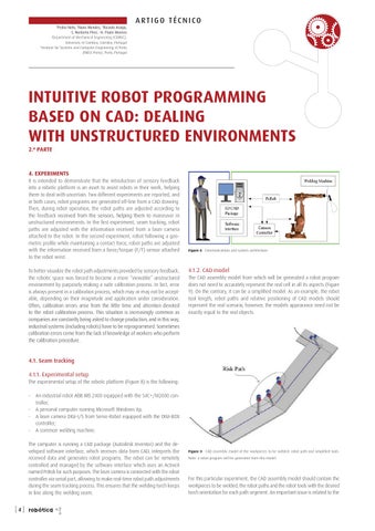
Figure 8 · Communications and system architecture.
4.1.2. CAD model The CAD assembly model from which will be generated a robot program does not need to accurately represent the real cell in all its aspects (Figure 9). On the contrary, it can be a simplified model. As an example, the robot tool length, robot paths and relative positioning of CAD models should represent the real scenario, however, the models appearance need not be exactly equal to the real objects.
4.1. Seam tracking 4.1.1. Experimental setup The experimental setup of the robotic platform (Figure 8) is the following: -
An industrial robot ABB IRB 2400 equipped with the S4C+/M2000 controller; A personal computer running Microsoft Windows Xp; A laser camera DIGI-I/S from Servo-Robot equipped with the DIGI-BOX controller; A common welding machine.
The computer is running a CAD package (Autodesk Inventor) and the developed software interface, which receives data from CAD, interprets the received data and generates robot programs. The robot can be remotely controlled and managed by the software interface which uses an ActiveX named PcRob for such purposes. The laser camera is connected with the robot controller via serial port, allowing to make real-time robot path adjustments during the seam tracking process. This ensures that the welding torch keeps in line along the welding seam.
[4]
robótica
Figure 9 · CAD assembly model of the workpieces to be welded, robot path and simplified tools. Note: a robot program will be generated from this model.
For this particular experiment, the CAD assembly model should contain the workpieces to be welded, the robot paths and the robot tools with the desired torch orientation for each path segment. An important issue is related to the