Américo Costa CENFIM – Centro de Formação Profissional da Indústria Metalúrgica e Metalomecânica
Practical Case – 1 Vice Part 1
3D printing offers multiple benefits, such as: a quick and efficient communication of project ideas; effective design validation; a formal and/or functional analysis. It also offers greater project flexibility, allowing to swiftly execute multiple iterations of an object so as to validate the concept at hand; the ability to correct flaws and improve the production quality and the final products themselves. A reality seems to be the indispensability of a digital model in order to obtain a physical version via 3D printing. The following tutorial presents a practical case, a mechanical vice (figure 1), fabricated using 3D printing and FDM technology.
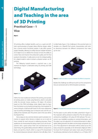
to slide freely, figure 2. Our challenge in this practical task is to simulate, on a Raise3D Pro2 printer, characteristics with similar clearances between the different components that make up the vice.
robótica
42
especial sobre Fabricação aditiva
Digital Manufacturing and Teaching in the area of 3D Printing
Figure 2. Guided and relative movement between the different components
Besides this challenge we still have to print out the components that are connected with an M10 threaded connection.
Figure 1. Vice
FDM is the more traditional method of 3D printing, and consists of printing pieces or molds using filaments, which is extruded while the extruder moves, creating a 3D object. 3D printers based on this FDM technology create objects layer by layer, from the bottom up, by heating and ejecting a thermoplastic filament through a small extruder head. It’s the most widespread type of printing technology due to reduced costs and the versatility of the materials used. The printer used in this case will be the Raise3D Pro2. Vices or jigs are very common devices used in precision mechanics to support other devices or objects so as to work on them, namely for swarf removal or soldering processes. These appliances are characterised for being made up of a set of components with a good surface finish and manufactured to be close fitting. The guided sliding between different components leads us to opt for a H/g fit, which is a type of fit characterised by minimal clearances between elements that still allow them
Figure 3. A threaded M10 connection between the two components shown
The first piece to print will be the slider, presented in figure 4. The material it will be printed in is black PLA. The 3D model was achieved by modelling in 3D using 3D CAD software. The component was modelled according to nominal dimensions, and this object was not adjusted in its nominal dimensions to allow tighter sliding between the slider and the body component, figure 6. That adjustment in dimensions will be carried out on the body component, especially on the dimensions 30g6 and 10h8. To ensure the fit between each piece made using 3D printing has behaviour identical to that of a sliding fit, i.e., a H7/g6 or H8/