First published in Great Britain 1981; Second edition 1992
ISBN 978-184995-052-7
All rights reserved.
No part of this publication may be reproduced, stored in a retrieval system, or transmitted, in any form or by any means, electronic, mechanical, recording or otherwise without prior permission of the publishers.
The publisher and authors have used their best efforts in preparing this book, but assume no responsibility for any injury and/or damage to persons or property from the use or implementation of any methods, instructions, ideas or materials contained within this book. All operations should be undertaken in accordance with existing legislation, recognized codes and standards and trade practice. Whilst the information and advice in this book is believed to be true and accurate at the time of going to press, the authors and publisher accept no legal responsibility or liability for errors or omissions that may have been made.
Printed and bound in
3.3
3.4
3.4.1
3.4.2
3.4.3
3.5
3.6
3.7
4.1
5.1
5.2
5.3
4.2.1
5.4
5.1.1
5.3.1
5.3.2
5.3.3
5.3.4
5.4.1
5.4.2
7.1
7.2
8.6
Preface
In 2010, a new suite of design codes was introduced into the UK. As such, the British Standard Codes of Practice 8110 Structural Use of Concrete and 8007 Design of Concrete Structures for Retaining Aqueous Liquids were replaced by Eurocode 2 (BS EN 1992-1-1) and Eurocode 2 Part 3 (BS EN 1992–3), respectively, both with accompanying UK specific National Application Documents. The guidance provided by these new codes is quoted as being much more theoretical in its nature and is therefore fundamentally different to the traditional step-by-step guidance that has been offered for many years in the UK by the British Standards. The approach of these new replacement codes is therefore a step change in design guidance, requiring much more interpretation.
The third edition of this book, whilst adopting a similar structure to the first two editions, has attempted to reflect this more theoretical approach. The new codes represented an opportunity to improve the guidance, based on a greater depth of research and practical experience gained over the last two decades. Unfortunately, the improvements are not as extensive as would have been hoped, partly because much research to corroborate some of the proposed new theory is still ongoing. In order to accommodate this position, the book offers an insight into some of the remaining shortcomings of the code and the potential improvements to the efficiency of design and possible innovations that are possible and which can hopefully be included in the planned revision of the codes in 2020.
JPF and AJM
Acknowledgements
I met Andrew Beeby for the first time in 1997; later, in 1999 the opportunity arose for me to join the Structures Group at the University of Leeds; I took up the position because Andrew was the head of that group. I have always felt privileged to have been able to call Andrew my mentor, a role which continued even after he retired; at which point in time I could more accurately and proudly call him my friend. I have never known anyone more insightful. His passing in 2011 was an extremely sad time. He was a true gentleman, possessing rare qualities; I give my thanks for his guidance, knowledge, motivation and friendship.
I would also like to thank all the engineers and researchers who have contributed to the better understanding of this fascinating topic of water retaining structures, past and present.
JPF, Leeds
Structural engineering is a fascinating subject and I acknowledge with grateful thanks all those who have influenced my education, training and development as an engineer throughout my career. I am grateful to Matt Kirby for permission to use the photograph reproduced in Figure 1.2. My contribution to this book is dedicated to my family and especially to my father Geoffrey H. Martin (1929–2013).
AJM, Copenhagen
We are both very grateful to Bob Anchor for this opportunity to produce the third edition of his book. His contribution to the design of water retaining structures is now into its fifth decade – an outstanding achievement.
Chapter 1 Introduction
1.1 Scope
It is common practice to use reinforced or prestressed concrete structures for the storage of water and other aqueous liquids. Similar design methods may also be used to design basements in buildings where groundwater must be excluded. For such purposes as these, concrete is generally the most economical material of construction and, when correctly designed and constructed, will provide long life and low maintenance costs. The design methods given in this book are appropriate for the following types of structure (all of which are in-line with the scope of Part 3 of Eurocode 2, BS EN 1992-3, 2006): storage tanks, reservoirs, swimming pools, elevated tanks (not the tower supporting the tank), ponds, settlement tanks, basement walls, and similar structures (Figures 1.1 and 1.2). Specifically excluded are: dams, structures subjected to dynamic forces, and pipelines, aqueducts or other types of structure for the conveyance of liquids.
It is convenient to discuss designs for the retention of water, but the principles apply equally to the retention of other aqueous liquids. In particular, sewage tanks are included. The pressures on a structure may have to be calculated using a specific gravity greater than unity, where the stored liquid is of greater density than water. Throughout this book it is assumed that water is the retained liquid unless any other qualification is made. The term ‘structure’ is used in the book to describe the vessel or container that retains or excludes the liquid.
The design of structures to retain oil, petrol and other penetrating liquids is not included (the code (BS EN 1992-3, 2006) recommends reference to specialist literature) but the principles may still apply. Likewise, the design of tanks to contain hot liquids (> 200°C) is not discussed.
1.2 General design objectives
A structure that is designed to retain liquids must fulfil the requirements for normal structures in having adequate strength, durability, and freedom from excessive cracking or deflection. In addition, it must be designed so that the liquid is not allowed to leak or percolate through the concrete structure. In the design of normal building structures, the most critical aspect of the design is to ensure that the structure retains its stability under the applied (permanent and variable) actions. In the design of structures to retain liquids, it is usual to find that if the structure has been proportioned and reinforced so that the liquid is retained without leakage (i.e. satisfying the Serviceability Limit State, SLS), then the strength (the Ultimate Limit State, ULS requirements)
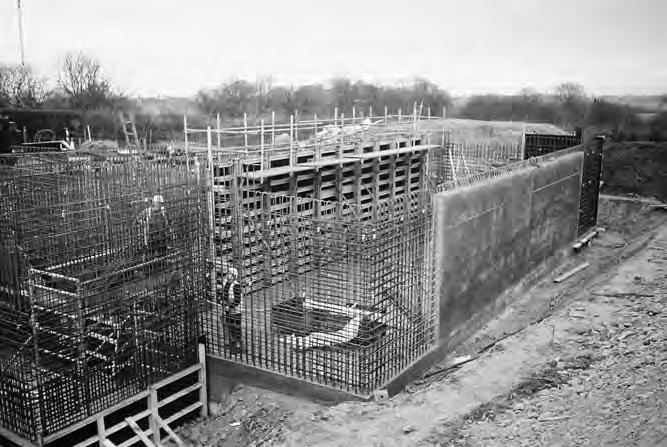
1.1 A tank under construction (Photo: J.P. Forth/A.P. Lowe).
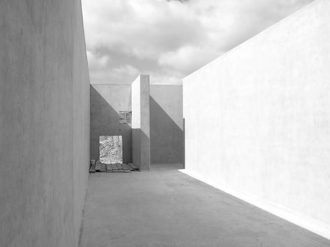
Figure 1.2 A concrete tank (before construction of the roof) illustrating the simplicity of the structural form (Photo: M.J. Kirby).
Figure
is more than adequate. The requirements for ensuring a reasonable service life for the structure without undue maintenance are more onerous for liquid-retaining structures than for normal structures, and adequate concrete cover to the reinforcement is essential. Equally, the concrete itself must be of good quality, and be properly compacted: good workmanship during construction is critical.
Potable water from moorland areas may contain free carbon dioxide or dissolved salts from the gathering grounds, which attack normal concrete. Similar difficulties may occur with tanks that are used to store sewage or industrial liquids. After investigating by tests the types of aggressive elements that are present, it may be necessary to increase the cover, the cement content of the concrete mix, use special cements or, under ‘very severe’ (BS EN 1992-1-1, 2004; BS 8500-1, 2006) conditions, use a special lining to the concrete tank.
1.3 Fundamental design methods
Historically, the design of structural concrete was based on elastic theory, with specified maximum design stresses in the materials at working loads. In the 1980s, limit state philosophy was introduced in the UK, providing a more logical basis for determining factors of safety. 2011 has seen the introduction of the new Eurocodes; BS 8110 and BS 8007 have been withdrawn, and in their place is a suite of new codes, including specifically BS EN 1992-1-1:2004 (Eurocode 2 Part 1 or EC2) and BS EN 1992-3: 2006 (Eurocode 2 Part 3 or EC2 Part 3) and their respective National Annexes. The new Eurocodes continue to adopt the limit state design approach. In ultimate design, the working or characteristic actions are enhanced by being multiplied by partial safety factors. The enhanced or ultimate actions are then used with the failure strengths of the materials, which are themselves modified by their own partial factors of safety, to design the structure.
Limit state design methods enable the possible modes of failure of a structure to be identified and investigated so that a particular premature form of failure may be prevented. Limit states may be ‘ultimate’ (where ultimate actions are used) or ‘serviceability’ (where service actions are used).
Previously, when the design of liquid-retaining structures was based on the use of elastic design (BS 5337), the material stresses were so low that no flexural tensile cracks developed. This led to the use of thick concrete sections with copious quantities of mild steel reinforcement. The probability of shrinkage and thermal cracking was not dealt with on a satisfactory basis, and nominal quantities of reinforcement were specified in most codes of practice. It was possible to align the design guidance relating to liquid-retaining structures with that of the Limit State code BS 8110 Structural Use of Concrete once analytical procedures had been developed to enable flexural crack widths to be estimated and compared with specified maxima (Base et al., 1966; Beeby, 1979) and a method of calculating the effects of thermal and shrinkage strains had been published (Hughes, 1976).
Prior to the introduction of BS 8007 in the 1980s, BS 5337 allowed designers to choose between either elastic or limit state design. It has often been said ‘A structure does not know how it has been designed’. Any design system that enables a serviceable structure to be constructed safely and with due economy is acceptable. However, since BS 8007 was introduced in the UK, limit state design has been used consistently
and perhaps more successfully for the design of liquid-retaining structures and, although it has now been withdrawn, there is no reason why this trend cannot continue with the introduction of these new Eurocodes, which continue to utilise this limit state design philosophy.
1.4 Codes of practice
Guidance for the design of water-retaining structures can be found in BS EN 1992-3 which provides additional guidance, specific to containment structures, to that found in BS EN 1992-1-1 (BS EN 1992-3 does not provide guidance on joint detail). This approach is not unusual as the superseded code BS 8007 also provided additional rules to those found in the over-arching Structural Use of Concrete code, BS 8110. However, whereas BS 8110 contained both guidance on the philosophy of design and the loads and their combinations to be considered in design, a different approach is adopted in the Eurocodes. BS EN 1992-1-1 is itself supported by the Eurocode (BS EN 1990:2002–commonly referred to as Eurocode 0) Basis of Structural Design and Eurocode 1(BS EN 1991–10 parts) Actions on Structures. BS EN 1990 guides the designer in areas of structural safety, serviceability and durability–it relates to all construction materials. BS EN 1991 actually supersedes BS 6399 Loading for Buildings and BS 648 Schedule of weights of building materials. All Eurocodes and their individual Parts are accompanied by a National Annex (NA) / National Application Document (NAD), which provide guidance specific to each individual state of the European Union, i.e. the UK National Application Document only applies to the UK. Values in these National Annexes may be different to the main body of text produced in the Eurocodes by the European Committee for Standardization (CEN).
There are two distinct differences between BS 8110/BS 8007 and the new Eurocodes, which will immediately be apparent to the designer. Eurocodes provide advice on structural behaviour (i.e. bending, shear etc.) and not member types (i.e. beams etc.). Also, Eurocodes are technically strong and fundamental in their approach–they do not provide a step-by-step approach on how to design a structural member.
1.5 Impermeability
Concrete for liquid-retaining structures must have low permeability. This is necessary to prevent leakage through the concrete and also to provide adequate durability, resistance to frost damage, and protection against corrosion for the reinforcement and other embedded steel. An uncracked concrete slab of adequate thickness will be impervious to the flow of liquid if the concrete mix has been properly designed and compacted into position. The specification of suitable concrete mixes is discussed in Chapter 2. Practically, the minimum thickness of poured in-situ concrete for satisfactory performance in most structures is 300 mm. Thinner slabs should only be used for structural members of very limited dimensions or under very low liquid pressures.
Liquid loss may occur at joints that have been badly designed or constructed, and also at cracks or from concrete surfaces where incomplete compaction has been achieved. It is nearly inevitable that some cracking will be present in all but the simplest and smallest of structures. If a concrete slab cracks for any reason, there is a possibility that liquid may leak or that a wet patch will occur on the surface. However,
INTRODUCTION
it is found that cracks of limited width do not allow liquid to leak (Sadgrove, 1974) and the problem for the designer is to limit the surface crack widths to a predetermined size. Cracks due to shrinkage and thermal movement tend to be of uniform thickness (although this does depend on the uniformity of the internal restraint) through the thickness of the slab, whereas cracks due to flexural action are of limited depth and are backed up by a depth of concrete that is in compression. Clearly, the former type of crack is more serious in allowing leakage to occur.
An important question is whether or not the cracks formed from the two cases mentioned above (Early Thermal and Loading) are additive. It is accepted that longterm effects may be complementary to early thermal cracking and in these instances steps are taken to reduce the limiting crack width for early deformations. However, currently there is no suggestion or process by which cracking resulting from early-age effects should be added to that resulting from structural loading. It has to be said that no problems have been recognised specific to this; however, it does not mean that it is not occurring. In fact, recent investigations by the author into shrinkage curvature have suggested that both extension of early age cracks and new cracks can occur on loading (Forth et al., 2004).
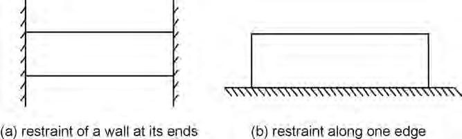
Before considering whether or not early-age cracking is additive with cracking from structural loading it is worth clarifying the conditions of external restraint to imposed deformation, which can result in this early-age cracking. This external restraint results from either end or edge (base) restraint. Figure 1.3 illustrates the two forms of restraint. These two types of restraint are really limiting forms of restraint. In practice, the situation is somewhat more complicated and the actual restraint is either a combination of these two forms or, more likely when early thermal movements are being considered in a wall, one of edge restraint (Beeby and Forth, 2005).
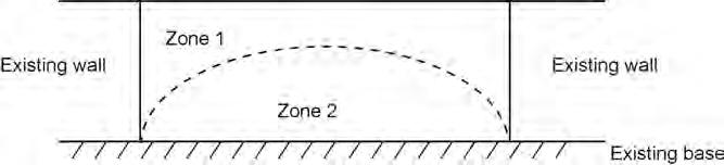
An example of where both forms of restraint exist can be found by considering a new section of concrete cast between two pre-existing concrete wall sections and onto a pre-existing concrete base. At the base, edge restraint will dominate (see Figure 1.4–Zone 2). However, further up the wall away from the base, edge restraint will become less significant and end restraint will become more influential. At a point within the height of the wall, end restraint will dominate and edge restraint becomes insignificant (see Figure 1.4–Zone 1). The position and significance of the two restraint conditions
Figure 1.3 External end and edge (base) restraint.
Figure 1.4 Approximate regions of domination of end (Zone 1) and edge (Zone 2) restraint in an infill wall
is obviously dependent on the height, cross section and length of the concrete section as well as the concrete base.
BS EN 1992-3 provides restraint factors, R for various wall and floor slab placing sequences (this figure is reproduced from BS 8007). Diagrammatically it attempts to describe the combination of the two types of external restraint described above, i.e. end and edge restraint, although the restraint factor, R is really only based on the structural model of a member restrained at its end against overall shortening.
On the matter of whether or not early age cracking can be compounded by load cracking, consider the example of a horizontal slab between rigid end restraints (Fig. L1 (b) of BS EN 1992-3). Due to end restraint conditions, a slab between rigid restraints will produce a primary crack, parallel to the rigid restraints most likely midway between the restraints. This is also the most likely position of a crack to form from structural loading. So although further investigations are required to confirm the presence of combined cracking, clearly in this case the opportunity exists.
In the case of a wall cast on a base, if the wall is sufficiently long then even without the restraint offered by adjacent wall panels a primary vertical crack may develop due to the edge restraint of early age movement. Structurally the wall will behave as a cantilever and structural cracking will therefore be horizontal in nature. In such a case, it is clear that early age cracking is not compounded by structural cracking. Taking this example one step further and considering Fig. L1 (d) of BS EN 1992-3, which illustrates a wall restrained at its base and by adjacent wall panels, diagonal cracks are predicted to occur at the base of the wall and near its ends. It is unsure as to whether these diagonal cracks would influence the formation and behaviour of structural cracking; further investigation is required.
As mentioned above, no problems have been identified that can be specifically explained by this potential combination of early-age and structural cracking. This could be because fortuitously, the code guidance for the design of water-retaining structures results in an over-estimation of steel required to resist imposed deformations. For edge-restrained situations, the crack width depends on the restrained imposed strain and not the tensile strength of the concrete (Al Rawi and Kheder, 1990). The amount of horizontal reinforcement is entirely dictated by that needed to control early thermal cracking (restraint to early thermal movement). Traditional detailing used about 0.2% of anti-crack reinforcement, whereas BS 8007 tended to require at least twice this amount (because of the intended use of the structure and the better control of crack
INTRODUCTION
widths required in water-retaining structures). The Eurocodes appear to require between 0.3 and 0.4%. These all relate to restraint of early thermal movement which, as discussed earlier, is based on the end restraint condition and not edge restraint. The question is one of whether this amount of steel is actually necessary.
1.6 Site conditions
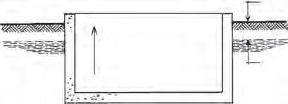
The choice of site for a reservoir or tank is usually dictated by requirements outside the structural designer’s responsibility, but the soil conditions may radically affect the design. A well-drained site with underlying soils having a uniform safe bearing pressure at foundation level is ideal. These conditions may be achieved for a service reservoir near to the top of a hill, but at many sites where sewage tanks are being constructed, the subsoil has a poor bearing capacity and the groundwater table is near to the surface. A high level of groundwater must be considered in designing the tanks in order to prevent flotation (Figure 1.5), and poor bearing capacity may give rise to increased settlement. Where the subsoil strata dip, so that a level excavation intersects more than one type of subsoil, the effects of differential settlement must be considered (Figure 1.6). A soil survey is always necessary unless an accurate record of the subsoil is available. Typically, boreholes of at least 150 mm diameter should be drilled to a depth of 10 m, and soil samples taken and tested to determine the sequence of strata and the allowable bearing pressure at various depths. The information from boreholes should be supplemented by digging trial pits with a small excavator to a depth of 3–4 m.
The soil investigation must also include chemical tests on the soils and groundwater to detect the presence of sulphates or other chemicals in the ground that could attack the concrete and eventually cause corrosion of the reinforcement (Newman and Choo, 2003). Careful analysis of the subsoil is particularly important when the site has previously been used for industrial purposes, or where groundwater from an adjacent tip may flow through the site. Further information is given in Chapter 2.
When mining activity is suspected, a further survey may be necessary and a report from the mineral valuer or a mining consultant is necessary. Deeper, randomly located boreholes may be required to detect any voids underlying the site. The design of a reservoir to accept ground movement due to future mining activity requires the provision of extra movement joints or other measures to deal with the anticipated movement and is outside the scope of this book (Davies, 1960; Melerski, 2000). In some parts of the world, consideration must be given to the effects of earthquakes, and local practice should be ascertained.
1.5 Tank
due
water. empty structure tends float ground level
Figure
flotation
to ground
top soil
sand
stiff clay soft clay rock
Figure 1.6 Effect of varying strata on settlement
1.7 Influence of execution methods
Any structural design has to take account of the constructional problems involved and this is particularly the case in the field of liquid-retaining structures. Construction joints in building structures are not normally shown on detailed drawings but are described in the specification. For liquid-retaining structures, construction joints must be located on drawings, and the contractor is required to construct the works so that concrete is placed in one operation between the specified joint positions. The treatment of the joints must be specified, and any permanent movement joints must be fully detailed. All movement joints require a form of waterstop to be included; construction joints may or may not be designed using a waterstop (BS 8102:2009). Details of joint construction are given in Chapter 5. In the author’s opinion, the detailed design and specification of joints is the responsibility of the designer and not the contractor. The quantity of distribution reinforcement in a slab and the spacing of joints are interdependent. Casting one section of concrete adjacent to another section, previously cast and hardened, causes restraining forces to be developed that tend to cause cracks in the newly placed concrete. It follows that the quantity of distribution reinforcement also depends on the degree of restraint provided by the adjacent panels.
Any tank that is to be constructed in water-bearing ground must be designed so that the groundwater can be excluded during construction. The two main methods of achieving this are by general ground de-watering, or by using sheet piling. If sheet piling is to be used, consideration must be given to the positions of any props that are necessary, and the sequence of construction that the designer envisages (Gray and Manning, 1973).
1.8 Design procedure
As with many structural design problems, once the member size and reinforcement have been defined, it is relatively simple to analyse the strength of a structural member and to calculate the crack widths under load: but the designer has to estimate the size of the members that he proposes to use before any calculations can proceed. With liquid-retaining structures, crack-width calculations control the thickness of the member, and therefore it is impossible to estimate the required thickness directly unless the limited stress method of design is used.
An intermediate method of design is also possible where the limit state of cracking is satisfied by limiting the reinforcement stress rather than by preparing a full calculation. This procedure is particularly useful for sections under combined flexural and direct stresses.
1.9 Code requirements (UK)
BS EN 1992-3 is based on the recommendations of BS EN 1992-1-1 for the design of normal structural concrete, and the design and detailing of liquid-retaining structures should comply with BS EN 1992-1-1 except where the recommendations of BS EN 1992-3 (and the UK National Annex) vary the requirements. The modifications that have been introduced into the Eurocodes mainly relate to:
• surface zones for thick sections with external restraint;
• surface zones for internal restraint only;
• the critical steel ratio, ρcrit;
• the maximum crack spacing, Sr,max;
• edge restraint.
These modifications are suitably discussed by Bamforth (2007), Hughes (2008) and Forth (2008).
Chapter 2 Basis of design and materials
2.1 Structural action
It is necessary to start a design by deciding on the type and layout of structure to be used. Tentative sizes must be allocated to each structural element, so that an analysis may be made and the sizes confirmed.
All liquid-retaining structures are required to resist horizontal forces due to the liquid pressures. Fundamentally there are two ways in which the pressures can be contained:
(i) by forces of direct tension or compression (Figure 2.1);
(ii) by flexural resistance (Figure 2.2).
Structures designed by using tensile or compressive forces are normally circular and may be prestressed (see Chapter 4). Rectangular tanks or reservoirs rely on flexural action using cantilever walls, propped cantilever walls or walls spanning in two directions. A structural element acting in flexure to resist liquid pressure reacts on the supporting elements and causes direct forces to occur. The simplest illustration (Figure 2.3) is a small tank. Additional reinforcement is necessary to resist such forces unless they can be resisted by friction on the soil.
2.2 Exposure classification
Structural concrete elements are exposed to varying types of environmental conditions. The roof of a pumphouse is waterproofed with asphalt or roofing felt and, apart from a short period during construction, is never externally exposed to wet or damp conditions. The exposed legs of a water tower are subjected to alternate wetting and drying from rainfall but do not have to contain liquid. The lower sections of the walls of a reservoir are always wet (except for brief periods during maintenance), but the upper sections may be alternately wet and dry as the water level varies. The underside of the roof of a closed reservoir is damp from condensation–because of the waterproofing on the external surface of the roof, the roof may remain saturated over its complete depth. These various conditions are illustrated in Figure 2.4.
Experience has shown that, as the exposure conditions become more severe, precautions should be taken to ensure that moisture and air do not cause carbonation in the concrete cover to the reinforcement thus removing the protection to the steel and causing corrosion, which in turn will cause the concrete surface to spall (Newman, 2003). Adequate durability can normally be ensured by providing a dense well-compacted concrete mix (see Section 2.5.2) with a concrete cover (cast against formwork) in the
section section
plan a)b) plan
Figure 2.1 Direct forces in circular tanks. (a) Tensile forces (b) Compressive forces.
Figure 2.2 Direct forces of tension in wall panels of rectangular tanks. plan section elevation of one panel 2 way span reaction from next panel
Figure 2.3 Tension in floor of a long tank with cantilever walls.
Figure 2.4 Exposure to environmental conditions: (a) pumphouse roof, (b) water tower and (c) reservoir.
Wide surface cracks allowing moisture and air penetration and leakage or percolation of liquid
Figure 2.5 Effect of cracks.
region of at least 40 mm (BS 8500-1), but it is also necessary to control cracking in the concrete, and prevent percolation of liquid through the member (see Figure 2.5). Previously, for design purposes, BS 8110 conveniently classified exposure in terms of relative severity (i.e. mild, moderate, severe). However, exposure classification in Eurocode 2 is now related to the deterioration processes, i.e. carbonation, ingress of chlorides, chemical attack from aggressive ground and freeze/thaw. Acting alongside Eurocode 2 is a more comprehensive guide, BS 8500 (Parts 1 and 2), to assist in determining cover. For less severe exposure conditions, BS 8500 is perhaps less onerous than BS 8110. However, for more severe conditions the requirements of BS 8500 are different. This is important, as BS EN 1992-3 requires that all liquid-retaining structures should be designed for at least ‘severe’ conditions of
exposure. Where appropriate the ‘very severe’ and ‘extreme’ categories should be used. As an example, a water tower near to the sea coast and exposed to salt water spray would be designed for ‘very severe’ exposure.
As well as defining cover, durability requirements are also achieved by controlling cracking. For the serviceability limit state, the maximum (limiting) crack width is between 0.05 mm and 0.2 mm, depending on the ratio of the hydrostatic pressure to wall thickness. It should be noted that these limiting crack widths are actually equivalent to total crack width, i.e. in theory, early age, long term and loading (see comments in Chapter 1). The range of crack widths provided above is provided in BS EN 1992-3. General guidance on crack control is provided in Section 7.3 of BS EN 1992-1-1. Additional guidance is given in BS EN 1992-3 because of the nature of the structure. Early age thermal cracking may result in through cracks, which can lead to seepage or leakage. In water-retaining structures this could be deemed a failure. BS EN 1992-3 therefore provides a ‘Classification of Tightness’, shown below in Table 2.1. This tightness represents the degree of protection against leakage: 0 (zero) represents general provision for crack control in-line with BS EN 1992-1-1; 3 represents no leakage permitted. Tightness class 1 is normally acceptable for water-retaining structures. The requirement for ‘No leakage permitted’ does not mean that the structure will not crack but simply that the section is designed so that there are no through cracks. There is no crack width recommendation of 0.1 mm for critical aesthetic appearance in the new Eurocodes as there was in BS 8110. No rational basis for defining the aesthetic appearance of cracking exists. BS EN 1992-3 claims that for Tightness class 1 structures, limiting the crack widths to the appropriate value within the range stated above should result in the effective sealing of the cracks within a relatively short time. The ratios actually represent pressure gradients across the structural section. As such, the claim that cracks of 0.2 mm will ‘heal’ provided that the pressure gradient does not exceed 5 has not changed much to the claim in BS 8007. For crack widths of less than 0.05 mm, healing will occur even when the pressure gradient is greater than 35. The fact that these cracks do seal is not strictly only due to autogenous healing (i.e. self-healing due to formation of hydration products) as was claimed in BS 8007, but also possibly due to the fact that the crack becomes blocked with fine particles. As mentioned above, sealing under hydrostatic pressure is discussed in Clause 7.3.1 of BS EN 1992-3 and for serviceability conditions, the limit state appropriate for water retaining structures, crack widths are limited to between 0.05 and 0.2 mm. When considering appearance and durability, further guidance with respect to crack widths and their relationship with exposure conditions can be found in Clause 7.3.1 of BS EN 1992-1-1 and its NA (Table NA.4).
Table 2.1 Tightness classification.
Tightness class Requirements for leakage
0 Some degree of leakage acceptable, or leakage of liquids irrelevant.
1 Leakage to be limited to a small amount. Some surface staining or damp patches acceptable.
2 Leakage to be minimal. Appearance not to be impaired by staining.
3 No leakage permitted
2.3 Structural layout
The layout of the proposed structure and the estimation of member sizes must precede any detailed analysis. Structural schemes should be considered from the viewpoints of strength, serviceability, ease of construction, and cost. These factors are to some extent mutually contradictory, and a satisfactory scheme is a compromise, simple in concept and detail. In liquid-retaining structures, it is particularly necessary to avoid sudden changes in section, because they cause concentration of stress and hence increase the possibility of cracking.
It is a good principle to carry the structural loads as directly as possible to the foundations, using the fewest structural members. It is preferable to design cantilever walls as tapering slabs rather than as counterfort walls with slabs and beams. The floor of a water tower or the roof of a reservoir can be designed as a flat slab. Underground tanks and swimming-pool tanks are generally simple structures with constantthickness walls and floors.
It is essential for the designer to consider the method of construction and to specify on the drawings the position of all construction and movement joints. This is necessary as the detailed design of the structural elements will depend on the degree of restraint offered by adjacent sections of the structure to the section being placed. Important considerations are the provision of ‘kickers’ (or short sections of upstand concrete) against which formwork may be tightened, and the size of wall and floor panels to be cast in one operation.
2.4 Influence of construction methods
Designers should consider the sequence of construction when arranging the layout and details of a proposed structure. At the excavation stage, and particularly on water-logged sites, it is desirable that the soil profile to receive the foundation and floors should be easily cut by machine. Flat surfaces and long strips are easy to form but individual small excavations are expensive to form. The soil at foundation level exerts a restraining force (the force develops from the restraint of early thermal contraction and shrinkage) on the structure, which tends to cause cracking (Figure 2.6). The
a) b)
Figure 2.6 Cracking due to restraint by frictional forces at foundation level (a) Floor slab (b) Wall (indicative only).
frictional forces can be reduced by laying a sheet of 1 000 g polythene or other suitable material on a 75 mm layer of ‘blinding’ concrete. For the frictional forces to be reduced, it is necessary for the blinding concrete to have a smooth and level surface finish. This can only be achieved by a properly screeded finish, and in turn this implies the use of a grade of concrete that can be so finished (BS 8500-1, 2006; Teychenne, 1975; Palmer, 1977). A convenient method is to specify the same grade of concrete for the blinding layer as is used for the structure. This enables a good finish to be obtained for the blinding layer, and also provides an opportunity to check the strength and consistency of the concrete at a non-critical stage of the job. It also reduces the nominal cover, cnom (BS 8500-1, 2006).
The foundations and floor slabs are constructed in sections that are of a convenient size and volume to enable construction to be finished in the time available. Sections terminate at a construction or movement joint (Chapter 5). The construction sequence should be continuous as shown in Figure 2.7(a) and not as shown in Figure 2.7(b). By adopting the first system, each section that is cast has one free end and is enabled to shrink on cooling without end restraint (a day or two after casting), although edge restraint will still exist (see Chapters 1 and 5). With the second method, considerable tensions are developed between the relatively rigid adjoining slabs.
Previously, BS 8007 provided three design options for the control of thermal contraction and restrained shrinkage: continuous (full restraint), semi-continuous (partial restraint) and total freedom of movement. On the face of it, it appears that BS EN 1992-3 does not allow semi-continuous design and therefore partial contraction joints have been excluded. Therefore, Part 3 only offers two options: full restraint (no movement joints) and free movement (minimum restraint). For the condition of free movement, Part 3 recommends that complete joints (free contraction joints) are spaced at the greater of 5 m or 1.5 times the wall height. (This is similar to the maximum crack spacing of a wall, given in BS EN 1992-1-1 Section 7, with no or less than As, min bonded reinforcement within the tension zone, i.e. 1.3 times the height of the wall.) However, BS EN 1992-3 also states ‘a moderate amount of reinforcement is provided sufficient to transmit any movements to the adjacent joint’. This appears contradictory. Hence continuity steel, less than As, min is still permitted and semi-continuous joints are therefore still allowed.
Figure 2.7 Construction sequence (a) Preferred sequence (b) Not recommended (c) Effect of method (b) on third slab panel (cracks shown are illustrative only).
It is recommended that if partial contraction joints are used, continuity steel of at least As, min (or 50% of the full continuity steel) is used and in fact the recommended spacing of these partial contraction joints is similar to that proposed previously (approx 7.5 m).
BS EN 1992-3 does not actually provide any guidance on the spacing of full contraction joints, i.e. no continuity steel (the 15m between full contaction joints shown in part (a) of Figure 2.8 below illustrates the guidance previously available in BS 8007).
Alternatively, temporary short gaps may be left out, to be filled in after the concrete has hardened. A further possibility is the use of induced contraction joints, where the concrete section is deliberately reduced in order to cause cracks to form at preferred positions. These possibilities are illustrated in Figure 2.8. The casting sequence in the vertical direction is usually obvious. The foundations or floors are laid with a short section of wall to act as a key for the formwork (the kicker, Figure 2.9). Walls may be concreted in one operation up to about 8 m height.
Reinforcement should be detailed to enable construction to proceed with a convenient length of bar projecting from the sections of concrete, which are placed at each stage of construction. Bars should have a maximum spacing of 300 mm or the thickness of the slab and a minimum spacing dependent on size, but not usually less than 100 mm to allow easy placing of the concrete. Distribution or shrinkage
full contraction joint
contraction joint
Figure 2.8 Joints (a) Typical layout in a wall (b) Typical layout of temporary gaps in construction (c) Induced joints.
height of Kicker 100 to 150 mm
Figure 2.9 Joint between floor and wall
reinforcement should ideally be placed in the outer layers nearest to the surface of the concrete. In this position it has maximum effect. However, structural considerations (i.e. to maximise effective depth, d) may also influence the layering of the reinforcement in each face. Figure 2.8 also illustrates typical crack inducers that can be used at full or partial contraction joints.
2.5 Materials and concrete mixes
2.5.1 Reinforcement
Although the service tensile stress in the reinforcement in liquid-retaining structures is not always very high, it is standard practice to specify high-strength steel with a ribbed or deformed surface either in single bar form or as mesh.
BS EN 1992-1-1 Annex C permits a range of characteristic yield strengths between 400 and 600 MPa; the specified characteristic strength of reinforcement available in the UK is 500 MPa. The specified characteristic strength is a statistical measure of the yield or proof stress of a type of reinforcement. The proportion of bars that fall below the characteristic strength level is defined as 5% (Figure 2.10). A material partial safety factor (for Persistent and Transient loading, γm = 1.15) is applied to the specified characteristic strength to obtain the ultimate design strength. In the UK, high-yield bars are supplied in accordance with BS 4449: 2005 and BS 8666:2005. Both of these codes support BS EN 10080: 2007 but are stand-alone documents with no confliction with EN 10080. Three grades of high-yield steel (A to C) are listed in BS 4449. These gradings reflect the ductility of the steel, with grade C being the most ductile (suitable for seismic applications). In the UK, B500 steel denotes high-yield steel with a characteristic strength of 500 MPa; B500B denotes Normal grade B steel. However, it is not unknown for steel manufacturers to supply Grade C quality steel under the heading of Normal grade B steel. Grade B500A steel is provided for cold working.
The fact that plain round grade 250 MPa steel was excluded from BS 4449 reflects the fact that other standards are available for the specification of mild steel bars (BS EN 10025-1, 2004; BS EN 13877-3, 2004) and the fact that this grade was being used less frequently (CARES, 2012).
Welded fabric or mesh reinforcement is specified in BS 4483 (2005). It is available in four types from A to D. For water-retaining structures, type A or Square Mesh is most common. Square Mesh is manufactured using 10, 8, 7 or 6 mm diameter bars at 200 mm centres in both the longitudinal and transverse directions.
Frequency
Characteristicfyk
Design fyd = fyk/1.15
Mean fym
2.10
5% of strengths below fyk
Reinforcement Strength
=1% to 12% depending on steel grade
Reinforcement embedded in concrete is protected from corrosion by the alkalinity of the cement. As time passes, the surface of the concrete reacts with carbon dioxide from the air and carbonates are formed that remove the protection. In certain circumstances, where perhaps restricted for space or where greater risk mitigation is required, special types of reinforcement can be considered. Stainless steel bars are still popular in the UK and are specified in BS 6722 (1986). The cost of stainless steel bars is still approximately 10 to 12 times that of normal grade high-yield bars. Hot dipped galvanising is still used to protect steel in some applications. In general, normal grade steel is fabricated into reinforcement cages first before being dipped. Due to the problems encountered with epoxy-coated bars, the use of this type of treatment to bars in the UK is almost non-existent.
2.5.2 Concrete
The specification, performance, production and conformity of concrete are controlled by BS EN 206-1, which was introduced in 2000 with subsequent amendments in 2004 and 2005. However, the UK NA to BS EN 1992-1-1 requires the use of BS 8500, which is a complementary British Standard to BS EN 206-1 and which contains additional UK provisions.
British Standard 8500 uses ‘compressive strength classes’ to define concrete strengths. Its notation uses both cylinder and cube strength (i.e. C25/30–cylinder / cube). It provides guidance on specifying concrete (cement type, aggregates, admixtures etc.) and an assessment of cover and strength for durability. As such, it replaces BS 5328 and related sections of BS 8110-1.
Figure
Graphical definition of characteristic strength.
The detailed specification and design of concrete mixes is outside the scope of this book. However, a typical mix design for water-retaining structures is derived and provided in Chapter 6.
Cements
In recent years, there has been a great deal of progress made in improving the sustainability of concrete. This has been achieved through the manufacturing process of cements, the choice of aggregates and the reduction in CEM 1 (Portland cement) in the cements themselves. This reduction in volume of CEM 1 is achieved through the replacement of the Portland cement or by blending the Portland cement with other materials. However, the reduction in the overall volume of Portland cement is also driven by the desire to achieve concretes with greater variations in properties and performances (reduction in heat of hydration, quicker strength gain, greater frost resistance, reduced water content etc.). It should be noted that often an improvement in one property will be to the detriment of another–the designer can therefore have a lot to consider when considering both the technical and economic advantages that this new range of cements can provide. For instance, if the designer is required to specify a lower strength requirement it will not necessarily mean that the concrete will exhibit a loss of durability. Concretes containing cement replacement materials such as fly ash or ground granulated blastfurnace slag (GGBS) may offer better protection to rebar than CEM 1 concretes. An extensive investigation has been performed by Dhir et al. (2004); more information can also be obtained from Bamforth (2007).
Aggregates
The maximum size of aggregate must be chosen in relation to the thickness of the structural member. A maximum size of 20 mm is always specified up to member thickness of about 300–400 mm and may be used above this limit, particularly if larger aggregate sizes are not available. Size 40 may be specified in very thick members, if available. The use of a large maximum size of aggregate has the effect of reducing the cement content in the mix for a given workability, and hence reduces the amount of shrinkage cracking.
It is important to choose aggregates that have low drying shrinkage (the maximum drying shrinkage specified in BS 8500: Part 2 should be < 0.075%, unless otherwise specified) and low absorption. Most quartz aggregates are satisfactory in these respects but, where limestone aggregate is proposed, some check on the porosity is desirable. Certain aggregates obtained from igneous rocks exhibit high shrinkage properties and are quite unsuitable for use in liquid-retaining structures.
The aggregate type also has on influence on early thermal cracking in concrete. A preferred normal weight coarse aggregate is a crushed rock (crushed aggregates produce concretes with higher tensile strain capacity than rounded aggregates) with a low coefficient of thermal expansion. Typically, this applies to many limestones. Again, the designer has to consider carefully these factors when balancing the advantages and disadvantages. Even lower coefficients of thermal expansion are exhibited by lightweight aggregates; these produce concretes with even higher tensile strain capacities and are becoming more popular, as are the recycled concrete aggregates (RCA) and the recycled aggregates (RA), which are again specified in BS 8500 Parts 1 and 2.
Local suppliers can often provide evidence of previous use that will satisfy the specifier (in some instances, this is a requirement of BS 8500). Aggregates are expensive to transport and locally available material is preferable in terms of both cost and sustainability; however, some care is necessary when using material from a new quarry, and tests of the aggregate properties are recommended.
Admixtures
Admixtures are generally included to improve the strength and durability of the concrete. Typical admixtures are plasticisers and super-plasticisers, which can be used to increase the workability of the concrete, allowing it to be placed more easily with less consolidating effort, or to reduce the water content while maintaining workability (hence they are also known as water-reducing agents). An air-entraining agent is another admixture. These admixtures entrain air bubbles within the concrete, improving the freeze-thaw resistance of the concrete and hence its durability. However, whilst durability is improved, the strength may be reduced. As a general guide, for each 1% of entrained air there is a possible 5% reduction in compressive strength. Admixtures can also be added to slow the hydration of the cement, such as in large pours where partial setting before the pour is complete is clearly undesirable. Admixtures containing calcium chloride are not desirable as there is a risk of corrosion of the reinforcement.
Concrete mix design
The stages in the design of a concrete mix are as follows. Initially, the relevant exposure condition should be identified–each face of the structure and its individual element should be considered and apportioned an exposure class. Exposure classes in BS 8500 are related to the deterioration processes of carbonation (XC classes), freeze / thaw (XF classes), chloride ingress (XD and XS classes) and chemical attack, including sulphate attack, from aggressive ground. (BS 8500 refers the designer to the BRE Special Digest 1 (2005), which gives guidance on the assessment of the aggressive chemical environment for concrete class (ACEC), rather than the XA classes used in BS EN 206-1.) All of these X classes are sub-divided; it is likely that there will always be at least one relevant exposure class for each element.
Once the relevant exposure condition(s) have been identified, a strength class and cover (including permitted deviations) are chosen that will ensure a minimum 50-year working life of the structure.
The concrete must be designed to provide a mix that is capable of being fully compacted by the means available. Any areas of concrete that have not been properly compacted are likely to leak. The use of poker-type internal vibrators is recommended.
2.6 Loading
2.6.1
Actions
Characteristic values for actions (loads) are given in BS EN 1991 (Eurocode 1: Actions on Structures). Typically, liquid-retaining structures are subject to loading by pressure from the retained liquid. The nominal densities of materials are provided in BS EN 1992-1-1, however, this part does not provide the densities of all of the materials that may be stored in liquid-retaining structures. Table 2.2 provides the nominal density for typically retained liquids.
Table 2.2 Nominal density of retained liquids.
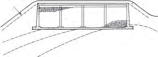
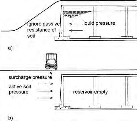
BS EN 1991 also provides specific guidance for Silos and Tanks (BS EN 1991-4). Guidance on Thermal actions (BS EN 1991-1-5) and Execution actions (BS EN 1991-1-6) can also be particularly relevant to the design of water-retaining structures. External reservoir walls are also often required to support soil fill. The soil loading conditions to be considered are illustrated in Figure 2.11–actual soil loading depends on the water table condition, the state of compaction of the backfill and whether native soil is used for the backfill. In the long-term it is likely that pressures will approach the ‘at-rest’ situation, although clay backfill may take many years to mobilise. For design, when the reservoir is empty, full allowance must be made for the ‘at rest’ or active earth pressure with the appropriate partial safety factors, assuming the backfill is carefully controlled, and any surcharge pressures from vehicles. When designing for the ‘reservoir full’ case, as a minimum the active earth pressure should be presumed. It is important to note that when designing for the condition with the reservoir full, no relief should be allowed from passive pressure of the soil fill. This is because of the differing moduli of elasticity of soil and concrete, which prevent the passive resistance of the soil being developed before the concrete is fully loaded by the pressure from the contained liquid (effectively, not enough strain can be generated in the soil to produce the passive pressure; however, it does depend on the method of backfill utilised and if the soil is overcompacted it is possible to create a situation where pseudo passive conditions exist).
At ultimate limit state–persistent and transient situations–three separate sets of load combinations (i.e. combinations of permanent and variable actions) are provided by Eurocode 0. These are (i) EQU, to be used if the structure is to be checked against loss of equilibrium; (ii) STR, to be used to check internal failure of the structure as governed by the strength of the construction materials (note, for this combination, the strength can be considered when the design does and does not also involve geotechnical actions); (iii) GEO, to be used when considering the failure of the ground or where the strength of the soil provides significant resistance. Under normal situations, typically, ULS (STR) and SLS limit states should be considered.
2.6.2 Partial safety factors
The designer must consider whether sections of the complete reservoir may be empty when other sections are full and design each structural element for the maximum bending moments and forces that can occur due to (a) the hydrostatic pressures alone and (b) the lateral earth, groundwater and possible surcharge pressures or a combination of the pressures from (a) and (b).
2.11 Design loadings for external walls with soil fill (a) Reservoir full (b) Reservoir empty.
As also directed by BS 8110 previously, the Eurocodes still design to the limit states by considering a combination of the permanent (dead) and variable (imposed) actions, where the characteristic actions are multiplied by an appropriate partial safety factor (psf). When designing a structural element for the ultimate limit state, it is necessary to use psfs (in conjunction with the characteristic actions) to provide the necessary margin against failure. The psfs take account of the likely variability of the loading and the consequences of failure.
For the case where the pressure is derived from the stored liquid alone (i.e. (a) above), the ULS (STR) operational safety factor, γF = 1.2, as provided in BS EN 1991-4 (Actions on Silos and Tanks). (Water = permanent action.). Under test, γF = 1.0.
For (b) above, it is usual to take the operational safety factor, γF = 1.35 for the permanent actions and γQ = 1.5 for the variable actions. Where there is more than one variable action, a multiplier, ψ0, is applied to the variable action partial safety factor to reflect the statistical improbability that more than one variable action will be a maximum simultaneously with the others. There are two other multipliers. Multiplier ψ1 is said to produce a frequent value of the load and multiplier ψ2 a quasi-permanent value of the load. The frequent and quasi-permanent multipliers are typically used at the ULS where accidental actions are involved. The quasi-permanent multiplier can also be used to determine long-term effects such as creep and settlement. Numerical values of ψ1 and ψ2 are provided in BS EN 1990.
It should be noted that any of the combinations of permanent and variable actions discussed above relate to the magnitude of loads that could be present. The designer is still required to perform the structural analysis to determine the actual arrangement of these loads in the structure to create the most critical effect.
A few final design comments: as the roofs of partially buried and underground reservoirs are covered with a solar attenuating layer composed of soil or gravel, any
Figure
imposed loads due to vehicles will be distributed before reaching the structural roof slab. In these circumstances, it will normally be appropriate to consider a single load/analysis case when designing the roof. Also, with respect to the roof of a reservoir, if the roof is monolithic with the walls, any thermal expansion of the roof may cause additional loading on the perimeter walls. BS EN 1991-1-5 (Thermal Actions) does provide some guidance on this effect; however, the guidance is more appropriate to bridge design. Research by the author is currently being performed (both in terms of monitoring a partially buried reinforced concrete service reservoir in North Yorkshire and full-scale laboratory testing) to quantify this type of thermal effect (Forth et al., 2005; Muizzu, 2009; Forth, 2012). BS EN 1991-4 (Actions–Silos and Tanks) does state that stresses resulting from the restraint of thermal expansion can be ignored if the number of expansion cycles provides no risk of fatigue failure or cyclic plastic failure. Although the number of thermal cycles are relatively low, output from the research being performed by the author does suggest caution when designing monolithic roof to wall joints, even in buried or partially buried structures due to additional moments from thermal creep.
For a reservoir with height of wall, H and an operating depth of water, h, BS EN 1991-4 (Silos and Tanks) recommends that for operational conditions a partial safety factor, γF = 1.2 should be used (i.e. 1.2ρh, where ρ = density of the liquid) to calculate the design load at ULS. For accidental situations, it recommends that γF = 1.0; however, the full depth of the wall should be used (i.e. 1.0ρH).
2.7 Foundations
It is desirable that a liquid-retaining structure is founded on good uniform soil, so that differential settlements are avoided (Chapter 1). However, this desirable situation is not always obtainable. Variations in soil conditions must be considered and the degree of differential settlement estimated (Barnes, 2000). Joints may be used to allow a limited degree of articulation, but on sites with particularly non-uniform soil, it may be necessary to consider dividing the structure into completely separate sections. Alternatively, cut-and-fill techniques may be used to provide a uniform platform of material on which to found the structure.
Figure 2.12 Propped cantilever walls on a cohesive soil (a) Structure (b) Basic structural assumptions (c) Rotation due to soil movement.
Soils that contain bands of peat or other very soft strata may not allow normal support without very large settlements, and piled foundations are required (Barnes, 2000; Manning, 1972).
The design of structures in areas of mining activity requires the provision of extra joints, the division of the whole structure into smaller units, or the use of rafts because of the potentially very large settlements. Prestressed tendons may be added to a normal reinforced concrete design to provide increased resistance to cracking when movement takes place (Davies, 1960; Melerski, 2000).
The use of partially buried cantilever walls depends on passive resistance to sliding between the base and the foundation soil. If the soil is inundated by groundwater, it may not be possible to develop the necessary resistance under the footing due to the high water pressures. In these circumstances, additional lateral restraint in terms of a toe would be required or alternatively in severe cases a cantilever design is not appropriate, and the overturning and sliding forces should be resisted by a system of beams balanced by the opposite wall, or by designing the wall to span horizontally if that is possible. When fully buried, it is reasonable to consider the resistance offered by the wall as well.
Walls that are designed as propped cantilevers, and where the roof structure can act as a tie, are often considered to have no rotation at the footing (Figure 2.12). However, the strain in a cohesive soil may allow some rotation and a redistribution of forces and moments.
ground level
ground water level
floor thickness to add weight
ground level
heel
ground water level
weight of soil on heel around tank increases downward load
Figure 2.13 Methods of preventing flotation (a) Additional dead weight (b) Provision of a heel.
2.8 Flotation
An empty tank constructed in water-bearing soil will tend to move upwards in the ground, or float. The ability of the structure to resist this uplift can be checked by comparing the permanent stabilising actions (i.e. self weight and side friction) to the permanent and variable destabilising actions from the groundwater and possibly other sources. Simplistically, the designer should ensure that any tendency towards uplift must be counteracted by ensuring that the weight of the empty tank structure is greater than the uplift equal to the weight of the groundwater displaced by the tank.
The extent to which the stabilising actions must be greater than the destabilising actions is defined in BS EN 1997-1:2004 (Eurocode 7). This code guides the designer in the assessment of the stability of the structure against hydraulic uplift. BS EN 1997-1 (more specifically its National Annex) stipulates the value of the partial safety factors to be used when checking the uplift limit state (UPL) for buoyancy / flotation. The partial safety factor to be applied to the permanent stabilising action of the water is 0.9 (γG;stb = 0.9, where stb = stabilising) and the partial safety factor for the destabilising action is 1.1 (γG;dst = 1.1, where dst = destabilising).
Practically, the weight of the tank may be increased by thickening the floor or by providing a heel on the perimeter of the floor to mobilise extra weight from the external soil (Figure 2.13). Whichever method is adopted, the floor must be designed against the uplift due to the groundwater pressure. In calculating the weight of the soil over the heel, it is important to realise that the soil is submerged in the groundwater. The effective density of the soil is therefore reduced. If the floor is thickened, it is possible to construct it in two separate layers connected together by ties. This has the advantage that reduced thermal reinforcement appropriate to the upper thickness may be used.
The designer should consider conditions during construction, in addition to the final condition, and specify a construction sequence to ensure that the structure is stable at each phase of construction.
Chapter 6 provides a design example that illustrates the use of the basic design materials and parameters presented in this chapter, including a UPL design check for stability against hydraulic uplift.
Note
[1] Typically, owing to the more stringent cover requirements of BS EN 1992-1-1 and BS 8500, the required cover has increased compared to that required previously in BS 8110 and BS 8007. This has implications on the calculated crack widths and, where the crack spacing is controlled by the reinforcement, the steel area required to control these crack widths. Cracking is discussed more in Chapters 3 and 5.
Chapter 3 Design of reinforced concrete
3.1 General
The basic design philosophy of liquid-retaining structures is discussed in Chapter 2. In this chapter, detailed design methods are described to ensure compliance with the basic requirements of strength and serviceability.
In contrast with normal structural design, where strength is the basic consideration, for liquid-retaining structures it is found that serviceability considerations control the design. The procedure is therefore:
(i) estimate concrete member sizes;
(ii) calculate the reinforcement required to limit the design crack widths to the required value;
(iii) check strength;
(iv) check other limit states;
(v) repeat as necessary.
The calculation of crack widths in a member subjected to flexural loading can be carried out once the overall thickness and the quantity of reinforcement have been determined.
3.2 Wall thickness
3.2.1 Considerations
All liquid-retaining structures include wall elements to contain the liquid, and it is necessary to commence the design by estimating the overall wall thickness in relation to the height. The overall thickness of a wall should be no greater than necessary, as extra thickness will cause higher thermal stresses when the concrete is hardening.
The principal factors that govern the wall thickness are:
(i) ease of construction;
(ii) structural arrangement;
(iii) avoidance of excessive deflections;
(iv) adequate strength;
(v) avoidance of excessive crack widths.
The first estimate of minimum section thickness is conveniently made by considering (i), (ii) and (iii).
It will be found that a wall thickness of about 1/10 of the span is appropriate for a simple cantilever (Table 3.1), and somewhat less than this for a wall that is restrained on more than one edge. Each factor is discussed in the following sections.
3.2.2 Ease of construction
If a wall is too thin in relation to its height, it will be difficult for the concrete to be placed in position and properly compacted. As this is a prime requirement for liquidretaining structures, it is essential to consider the method of construction when preparing the design. It is usual to cast walls up to about 8 metres high in one operation (note for panels over 7 m span, an adjustment must be made to the limiting span / depth ratios–see Section 3.2.5), and to enable this to be successfully carried out, the minimum thickness of a wall over 2 metres high should be not less than 250–300 mm. Walls less than 2 metres high may have a minimum thickness of 200 mm. A wall thickness less than 200 mm is not normally possible, as the necessary four layers of reinforcement cannot be accommodated with the appropriate concrete cover on each face of the wall. The wall may taper in thickness with height in order to save materials. Setting out is facilitated if the taper is uniform over the whole height of the wall (Figure 3.1).
3.2.3 Structural arrangement
Lateral pressure on a wall slab is resisted by a combination of bending moments and shear forces carrying the applied loads to the supports. The simplest situation is where the wall is a simple cantilever, with the maximum shear force and bending moment at
Table 3.1 Approximate minimum thickness h (mm) of R. C. Cantilever wall subjected to water pressure
Figure 3.1 Typical section through a wall
the base. This situation will require the thickest wall section as the bending moment is comparatively large. The most favourable arrangement is where a wall panel is held at all four edges and may be structurally continuous along the edges. In this case, the slab spans in two directions and in each direction there may be positive and negative moments. Each of the moments will be appreciably less than in the case of the simple cantilever, and hence a thinner wall is possible with less reinforcement to control cracking where the wall spans in two directions. The particular structural arrangement that is appropriate for a given design will depend on the relative spans in each direction and whether movement joints are required at any of the sides of the panel.
3.2.4 Shear resistance of reinforced concrete
Theoretically, shear in reinforced concrete flexural members is resisted by a combination of four factors:
(i) concrete in the compression zone;
(ii) dowell action of main reinforcement;
(iii) aggregate interlock across flexural (tension) cracks; (iv) shear link reinforcement.
Eurocode 2 respects the above theory and as such, the shear stress depends on the concrete strength, effective depth and tension steel ratio. As before in BS 8110, the recommended design guidance in BS EN 1992-1-1 is (i) that there is a shear stress below which only minimum shear reinforcement need be provided (shear reinforcement is provided in all structural elements) and (ii) the design shear stress should be less than the shear capacity of the section.
However, there is a subtle dissimilarity between the approach in BS EN 1992-1-1 and that presented previously in BS 8110. In the former, there are effectively three stages in the design for shear. The first stage is to determine the capacity of the concrete alone. Should this capacity not be sufficient to resist the design shear force, the steel required to resist the designed shear is then determined without any consideration of the concrete’s shear capacity (stage 2). Effectively, for the majority of structural beams, the shear capacity of the member will be calculated based only on the steel and ignoring the contribution of the shear capacity of the concrete. Stage 3 determines the specific area and spacing of the shear reinforcement.
It is inconvenient to use shear reinforcement in slabs because it is difficult to fix and it impedes the placing of the concrete. It is actually an inefficient use of steel. Therefore, in water-retaining structures, where the common element is a slab, shear design is performed by ensuring that the shear capacity of the concrete exceeds that of the (applied) design shear force, i.e. stage 1 above. (Stages 2 and 3 will not, therefore, be specifically discussed, although some reference will be made to the theory on which they are based. Details of stages 2 and 3 are adequately covered in the code and reference can also be made to several general texts on reinforced concrete (The Concrete Centre, 2005).)
According to BS EN 1992-1-1, the concrete shear force capacity, VRd,c is given as: VRd,c = b w d [(0.18/c) k (1001 fck)1/3 + 0.15cp] (units are N) (3.1)
where
(0.18/c) = CRd.c where c = 1.5 (partial factor for concrete)
k = (1 + (200/d)1/2) 2.0 (with d expressed in mm)
1 = As1 / b w d ≤ 0.02 where As1 = the area of tension reinforcement that extends beyond the section being considered by at least a full anchorage length plus one effective depth, d
cp is only included if there are axial forces within the member (discussed later)
In recognition of the fact that a member still possesses some shear strength even without any reinforcement, the minimum value for the concrete shear force capacity is: VRd,c = [0.035k3/2 fck ½] b w d (units in N)
In order to ensure that there is sufficient capacity in the concrete, the wall thickness should be adjusted to suit such that the concrete shear force capacity, VRd,c exceeds the applied shear force, VEd. Alternatively, the concrete shear stress capacity, vRd,c must exceed the applied shear stress, vEd, where vEd = VEd / 0.9 b w d. (Note: 0.9 is only relevant when sections are being designed using the Variable Strut Inclination Method–see below.) The values for CRd,c, k1 and vmin (where vmin = [0.035k3/2 fck ½]) are provided in the National Annex. The National Annex also provides guidance for cases where the concrete strength classes are higher than C50/60. Whereas in BS 8110 the design shear stress was limited to the lesser of 0.8√fcu or 5 N/mm2, BS EN 1992-1-1 recommends that the applied shear force VEd should always satisfy the condition:
where v = 0.6 [1–fck/250] ( fck in MPa)
From Eq. (3.1) above, it is clear that the capacity of the concrete to resist shear is influenced by the longitudinal tension steel. It is, therefore, reasonable to expect that the applied shear force, VEd will cause an additional force in the tension steel and this needs to be considered in the design. However, BS EN 1992-1-1 does not require this check when designing members that DO NOT require design shear reinforcement. However, it does specify this check when designing members that DO require shear reinforcement. This additional longitudinal tension force, ∆Ftd for sections reinforced with vertical links (i.e. links perpendicular to the horizontal or longitudinal axis of the section) is defined:
where is the angle between the concrete compression strut and the beam axis perpendicular to the shear force (1 ≤ cot ≤ 2.5; 22° ≤ ≤ 45°).
Owing to the method of design introduced in BS EN 1992-1-1 (the Variable Strut Inclination Method), it is easy to see how the compressive force in the inclined concrete strut needs to be balanced by a horizontal component tension force and therefore why the code requires the designer to consider this tension force due to the action of shear in the design of the tension steel. The code actually specifies that only half of this horizontal tension force is carried by the reinforcement in the tension zone. In all probability, the additional tension force due to shear will not be significant; it is unlikely that the required additional steel area when added to the area of bending steel will be greater than the area of steel already determined to satisfy the serviceability limit state. In fact, the additional force could probably be resisted by modifying the
detailing of the steel (i.e. increasing the curtailment lengths of the tension reinforcement). However, the authors recommend that it would be good practice to perform the check (see examples in Chapter 6) and that (in Eq. (3.3) above) should be taken as 45° (i.e. cot = 2.5) to be conservative.
Whereas in BS 8110, values of design concrete shear stress were tabulated in terms of percentage area of tension steel and effective depth for a concrete of 25 MPa strength, BS EN 1992-1-1 does not provide such guidance. However, an equivalent table can be derived from Eqs (3.1) and (3.2) above and this is presented as Table 3.2 below. The table provides values of vRd,c for slabs constructed with C30/35 concrete and without axial loads.
A comparison between the guidance provided in BS 8110 and the current BS EN 1992-1-1 shows that overall, the latter permits a lower shear stress before shear reinforcement is required (Moss and Webster, 2004). However, due to the minimum shear stress that can be carried according to BS EN 1992-1-1, the allowable shear stresses in this code tend to be higher for low reinforcement percentages (this difference is more obvious, the higher the strength of the concrete). It must be remembered that the theoretical behaviour of reinforced concrete in shear is difficult to analyse because of its complexity. The guidance presented in BS EN 1992-1-1, as was the case with BS 8110, is derived empirically from many experimental investigations. The differences between the current code and the old BS 8110, allowing for the new design method introduced in BS EN 1992-1-1, in many ways simply represent the additional test data that have been referenced, that were not considered or were not available when BS 8110 was drafted. A review by Collins et al. (2008) has still raised concerns over the ability of BS EN 1992-1-1 to safely predict the shear strength of members without links.
Shear
with
axial load
Equation (3.1) above for the design shear force resistance of members not requiring shear reinforcement (Expression 6.2a in BS EN 1992-1-1) also includes a term for
Table 3.2 Shear force resistance of members without shear reinforcement, VRd,c in kN (Class C30/35 concrete).