Portfolio
Chris Keen | Architectural Technician
Chris Keen | Architectural Technician
Environment Canterbury
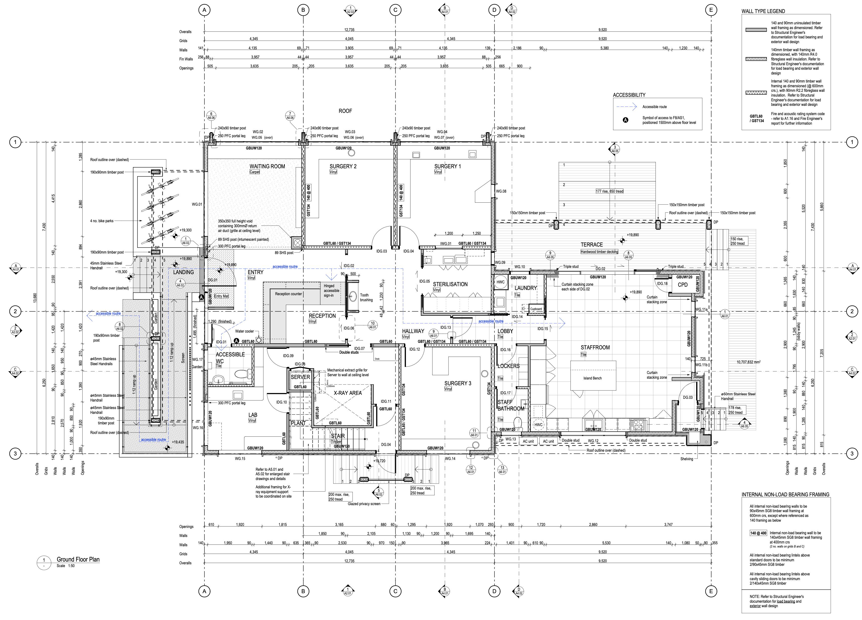
INFO Type: Office and Staff Facilities
Place: Kainga, Christchurch
Year: 2020 - 2021
Client: Environment Canterbury
Roles: Architectural Technician
Architectural BIM Manager
Document Controller
Phase: Developed Design
Working Drawings
Building Consent
DESCRIPTION
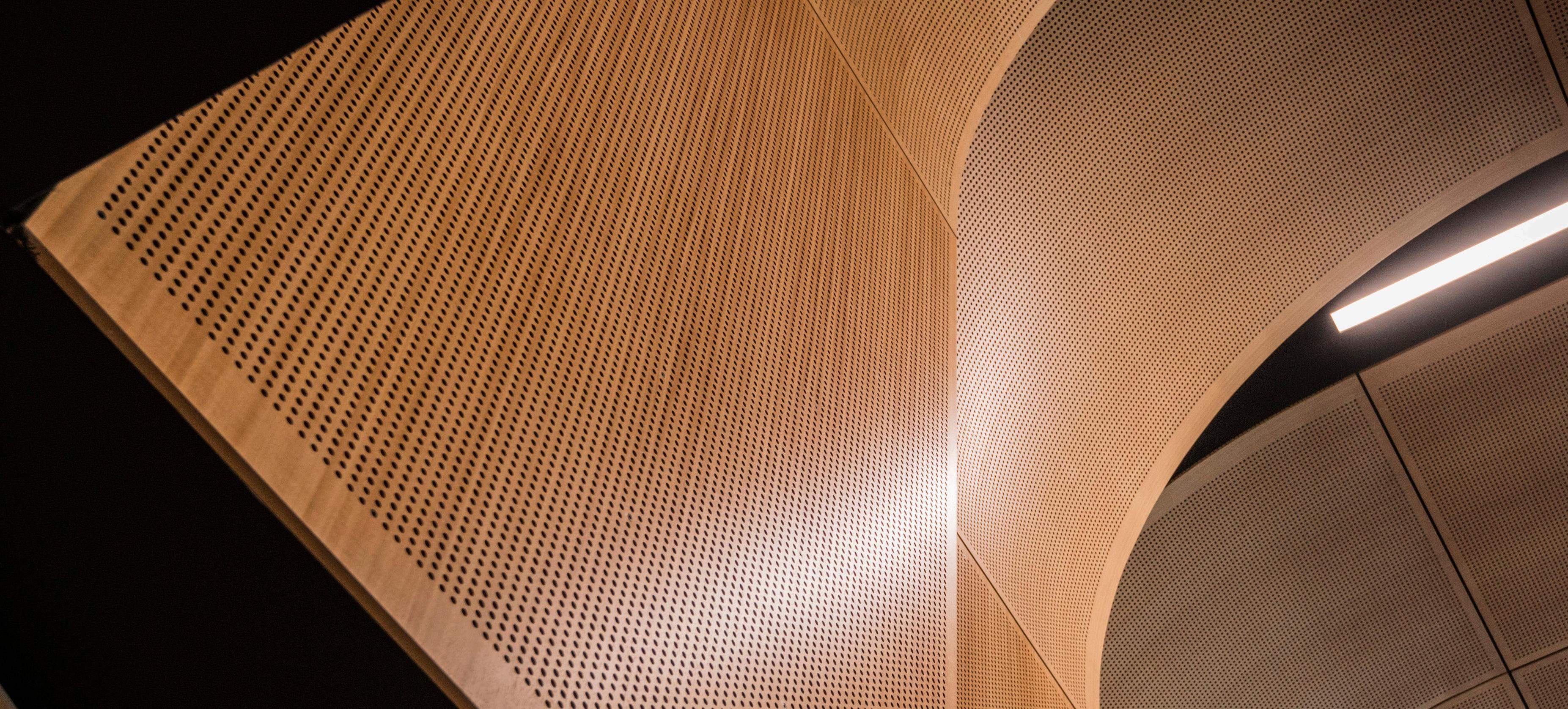
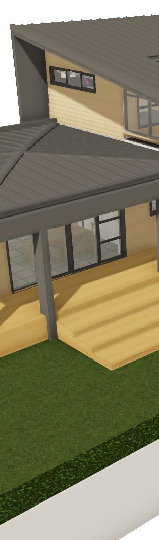
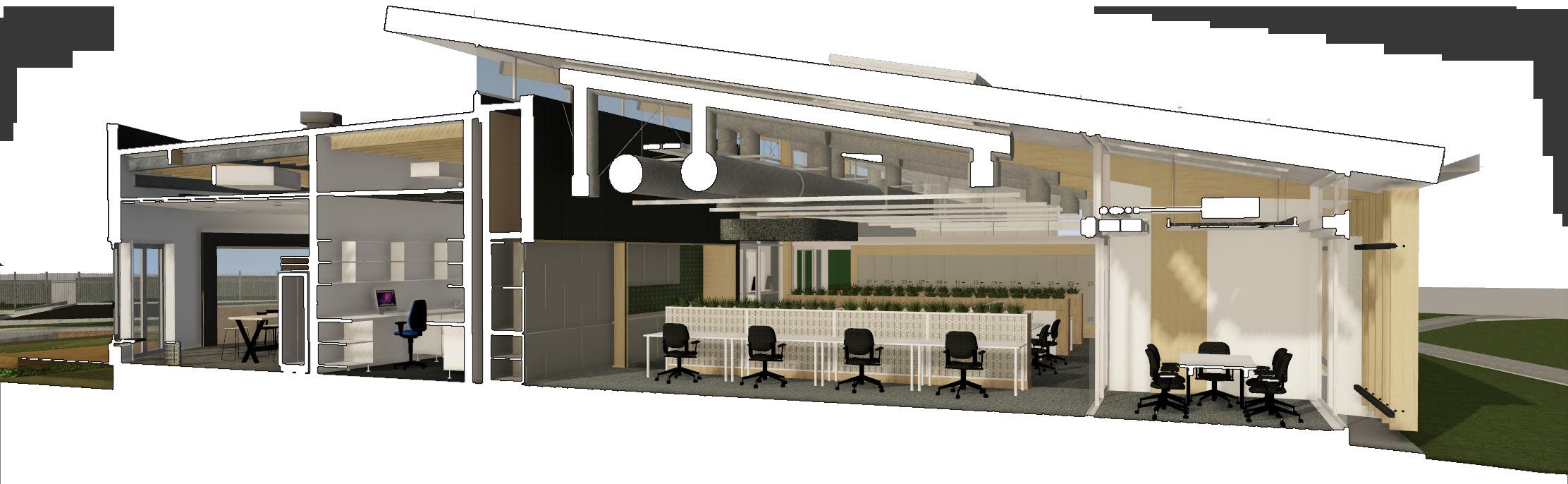
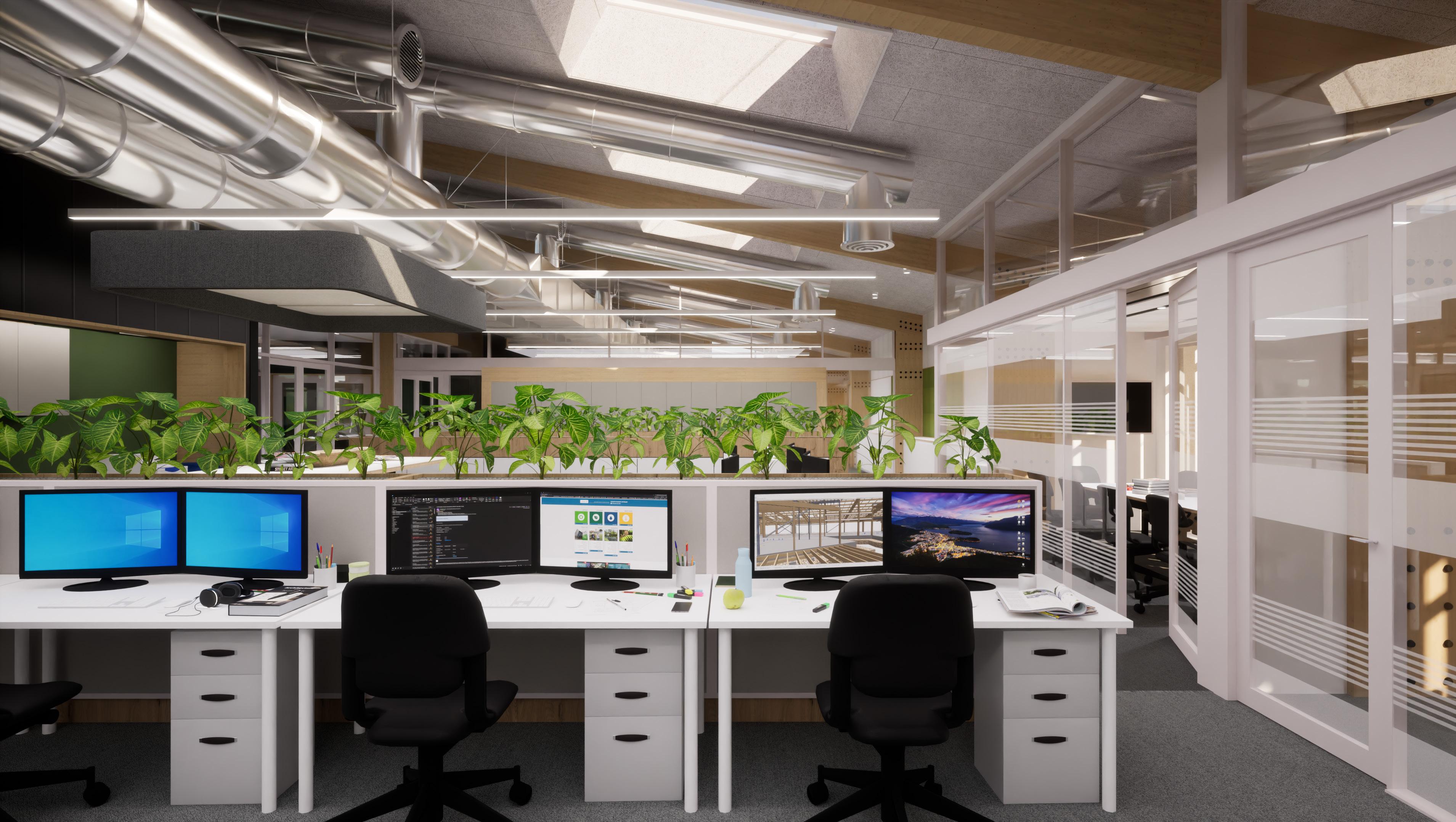
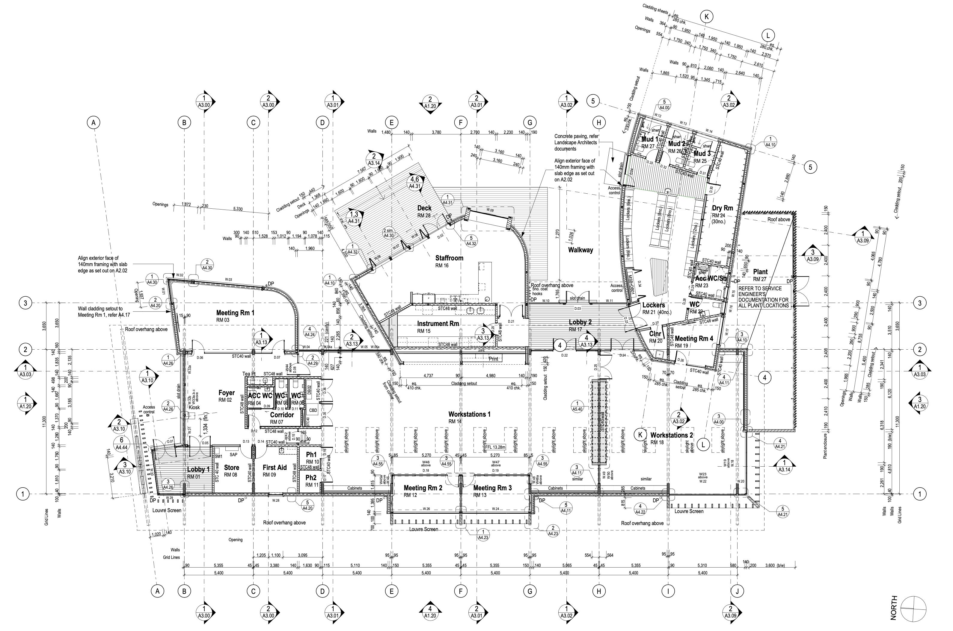
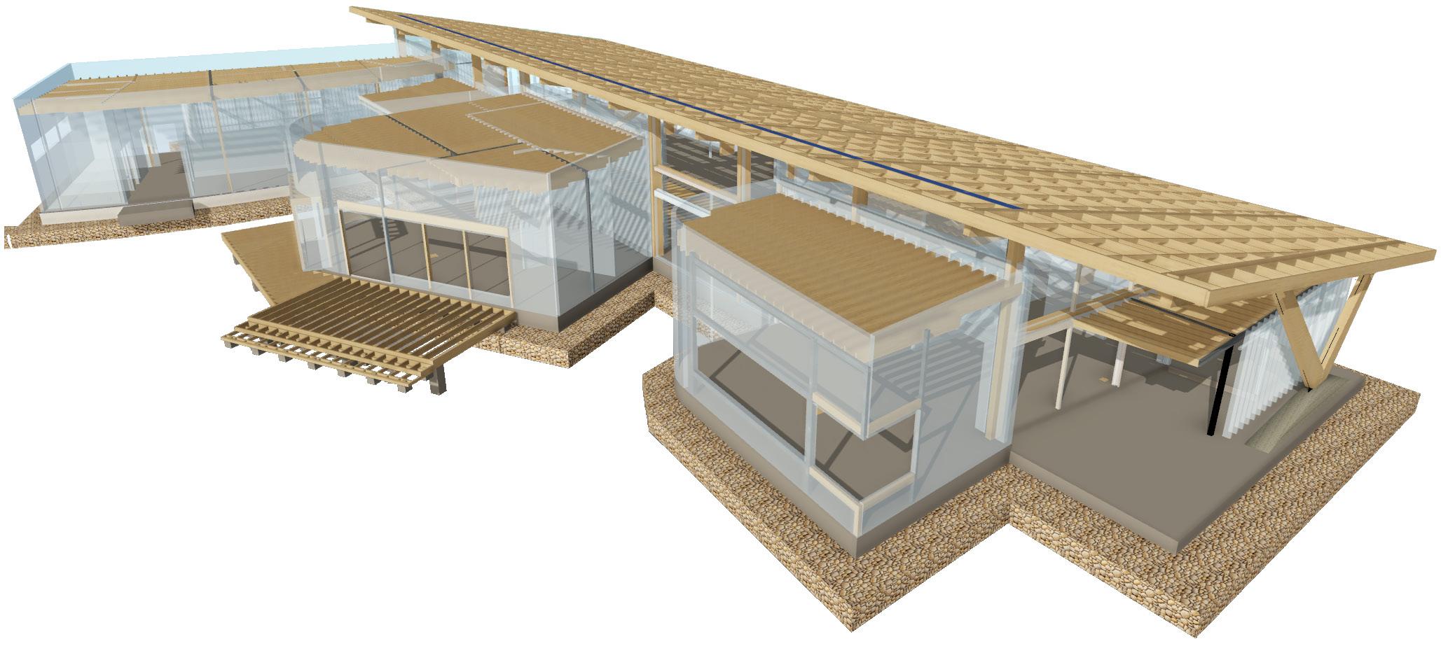
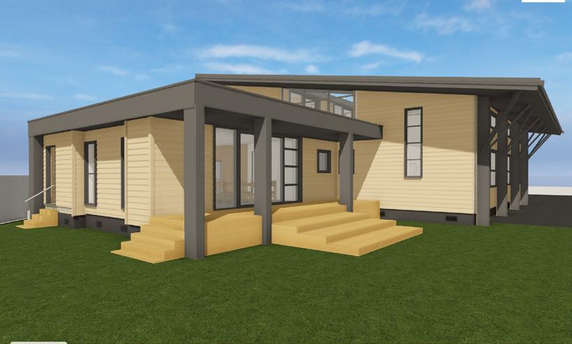
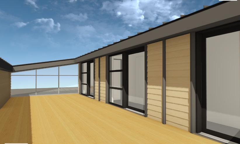
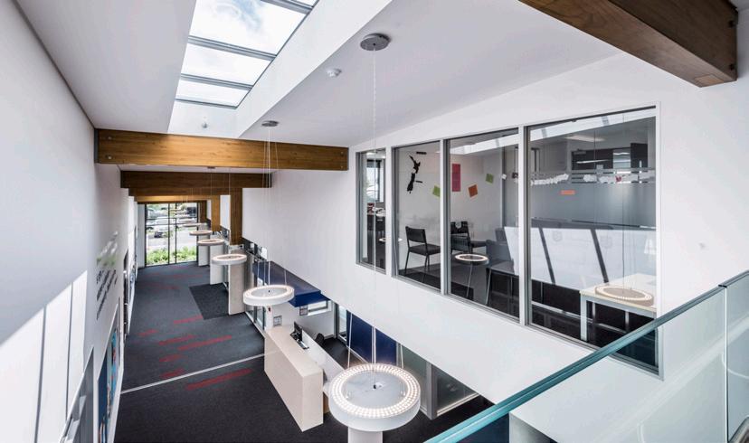
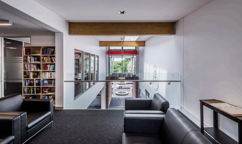
This new development for Environment Canterbury brings together a headquarters office building, storage facilities and yard areas for around 50 staff who work within the Canterbury region, from Rakaia up to Kaikoura.
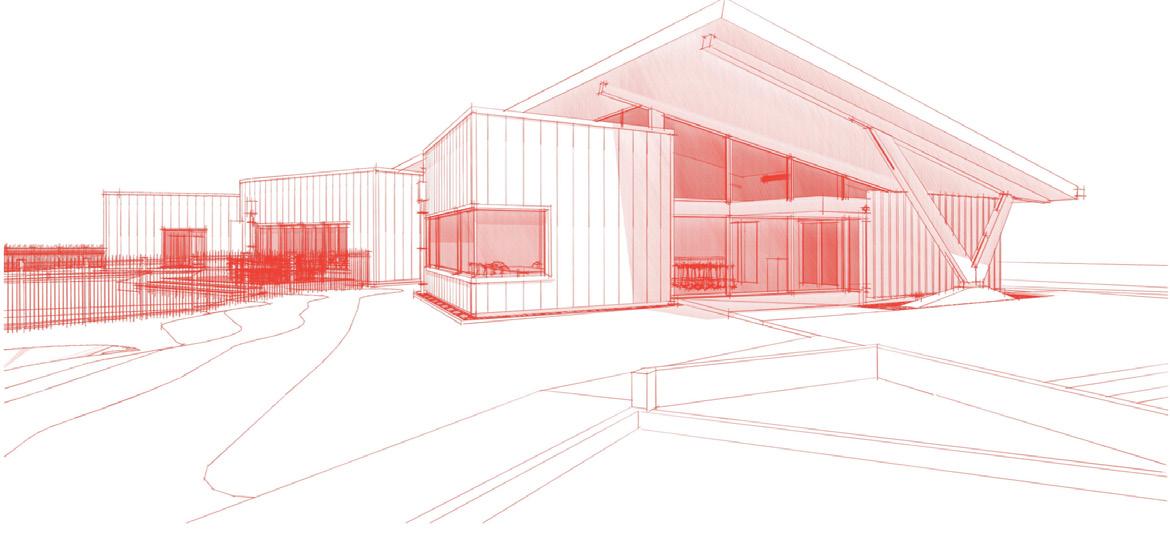
The development includes several sustainable design principles; lightweight glulaminated timber structure, high levels of insulation including warm roofs, rainwater harvesting and intentional solar shading. Sensitive site landscaping will enhance and retain existing surface water drainage swales across the site. The development is intended to be a 5-star Green Star rated project.
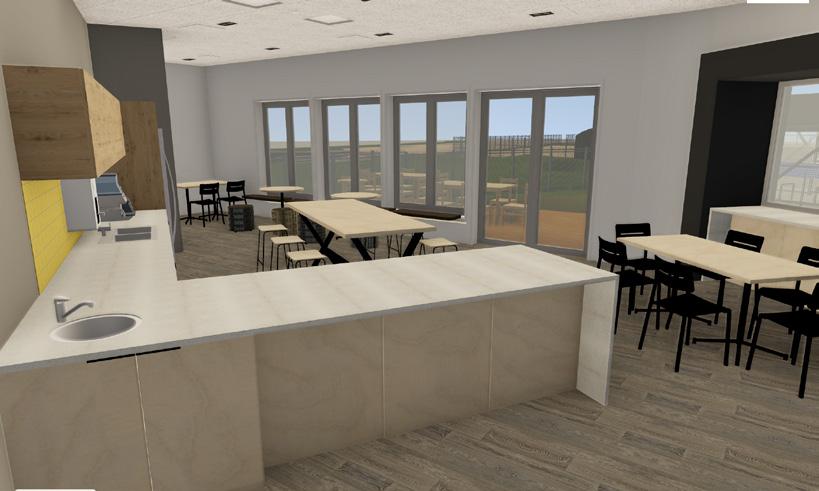
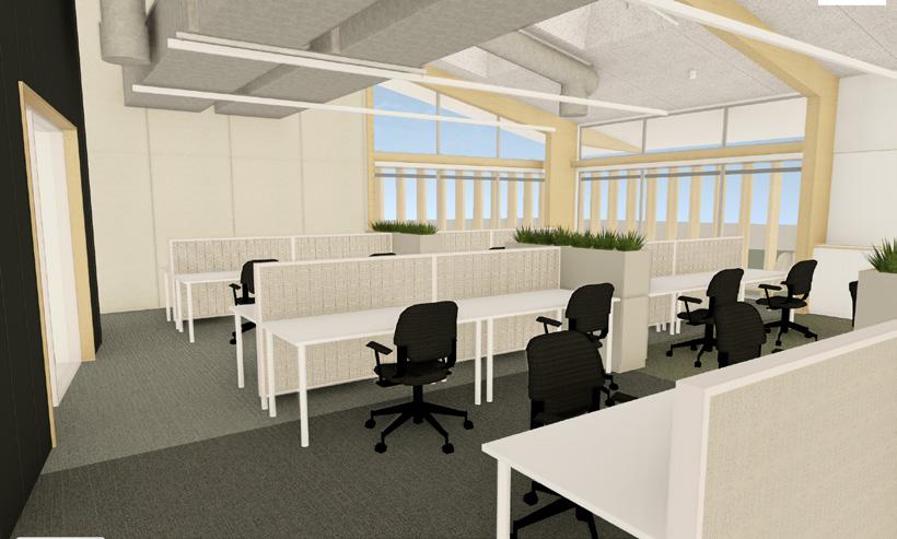
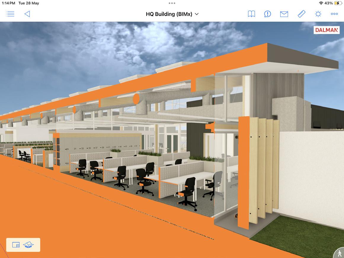
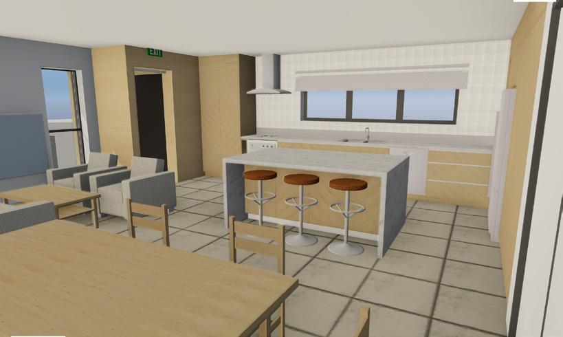
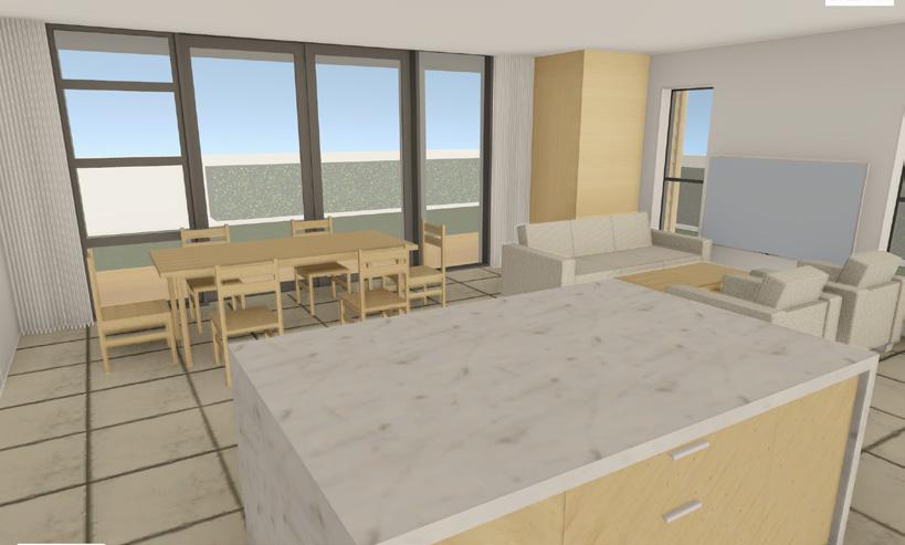
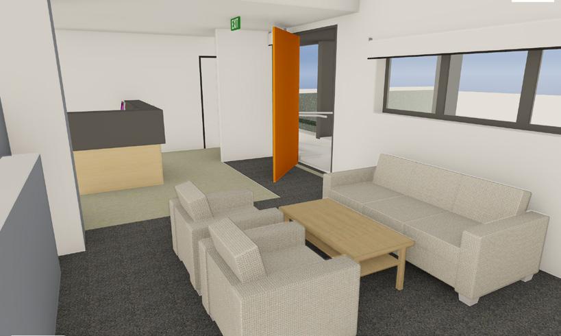
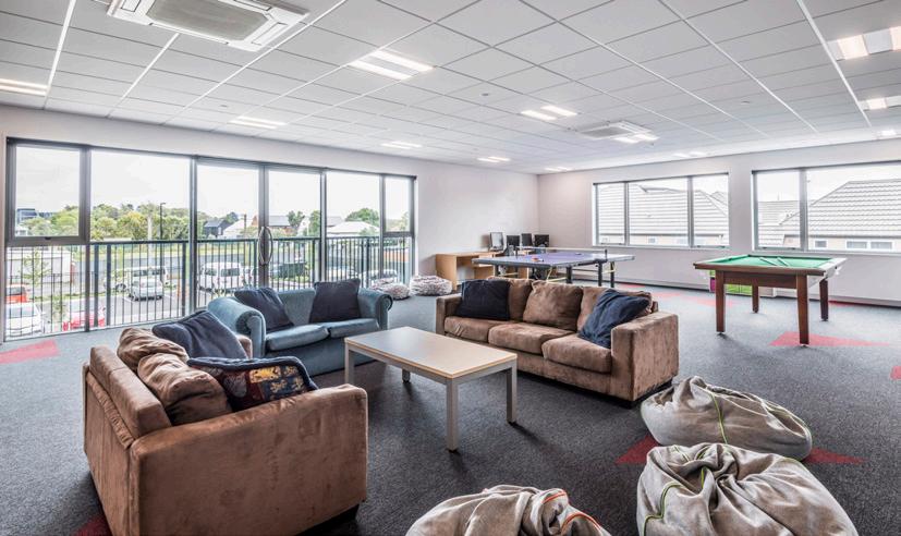
The interior layout of the office building was designed to suit a modern hot-desking office environment, with break-out spaces, meeting rooms, kitchen facilities and a large staff locker room. Acoustic absorption was applied to all ceilings.
Although not yet constructed, this was a notable project for me personally as I was able to utilise many sets of digital skills to aid in the development of a very successful design.
RESPONSIBILITIES
• Collaborating in-house with the project lead, a supporting senior architect, an interior designer and one other architectural technician.
• Setting out and coordinating the primary structure in collaboration with the structural engineer from day one, with ongoing adjustments as required.
• Coordinating with the MEP engineers which was critical to the success of the design due to many exposed services within the main office design.
• Coordinating suspended ceiling layouts between the architectural and services engineers to provide logical layouts.
• Extensive BIM modeling for visualisation and architectural documentation production which played a key role in the success of the project.
• Facilitating in-house virtual reality design reviews to assist with in-house communication.
• 2D visualisations to aid in the architect’s design review process.
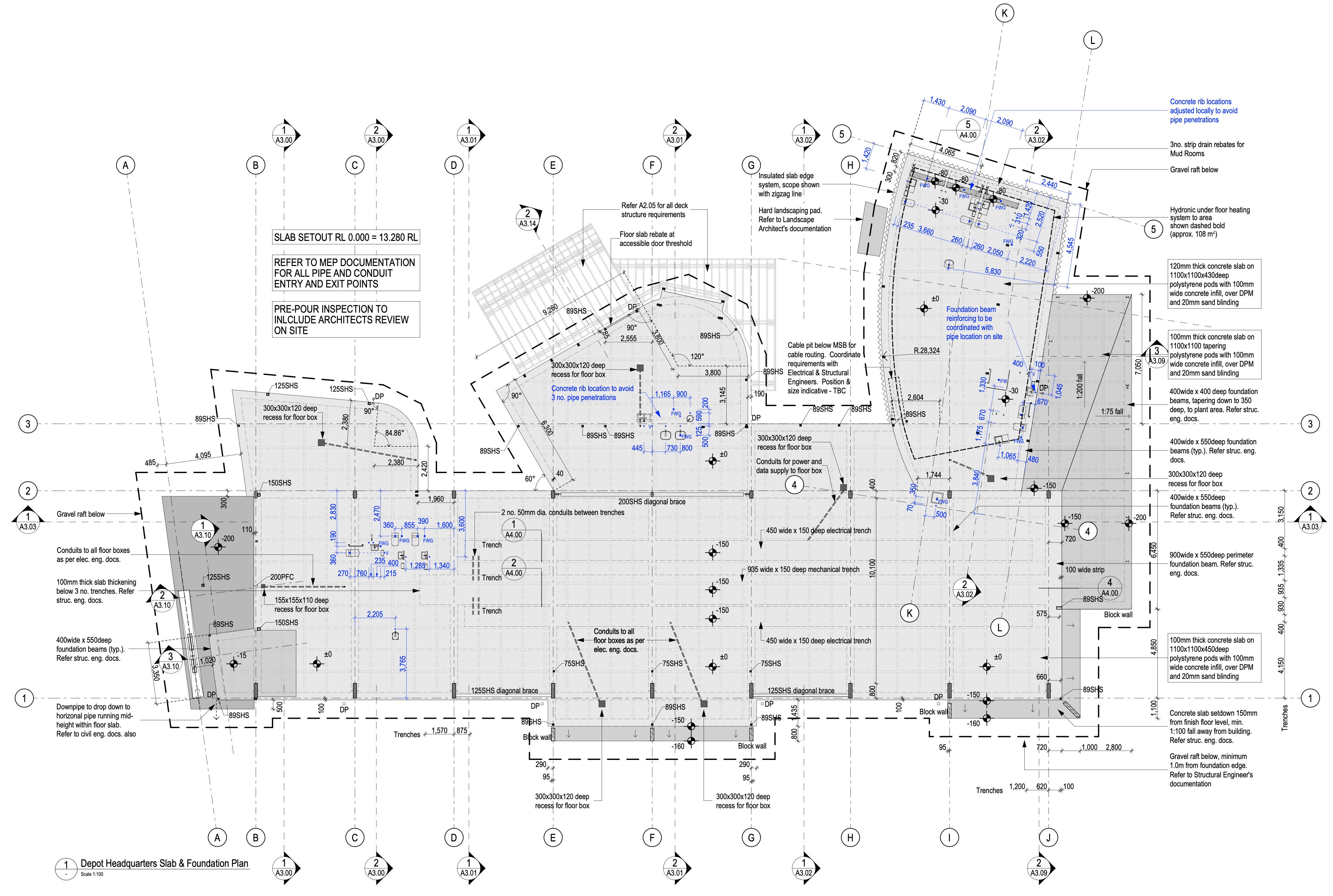
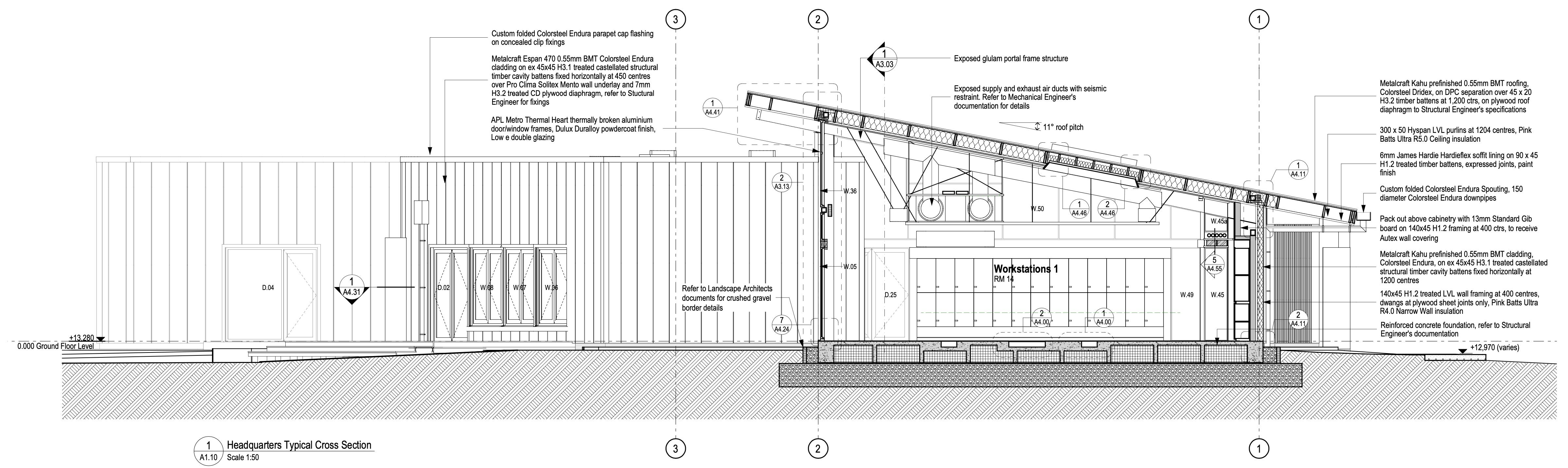
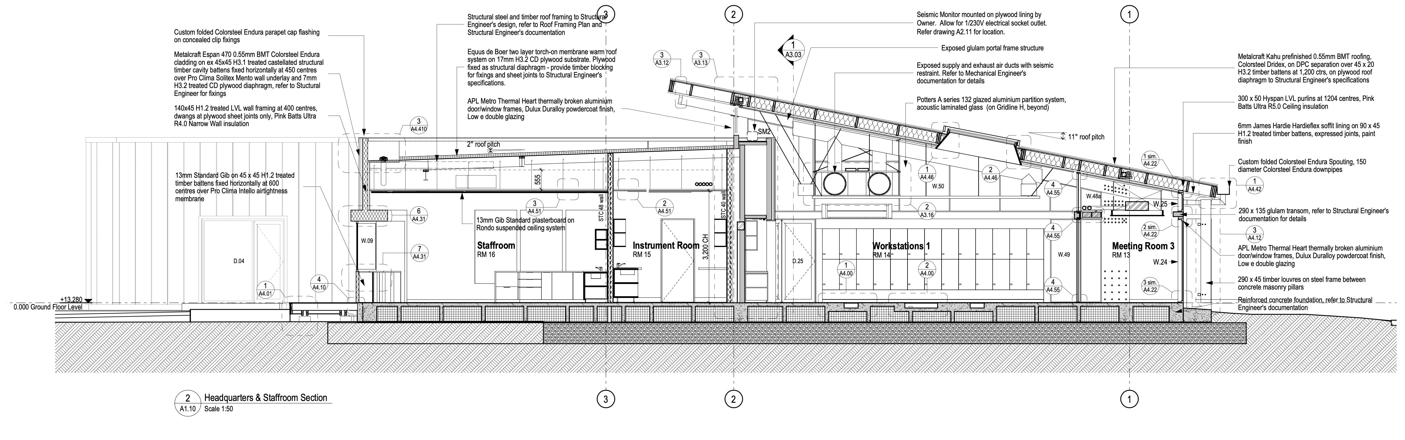
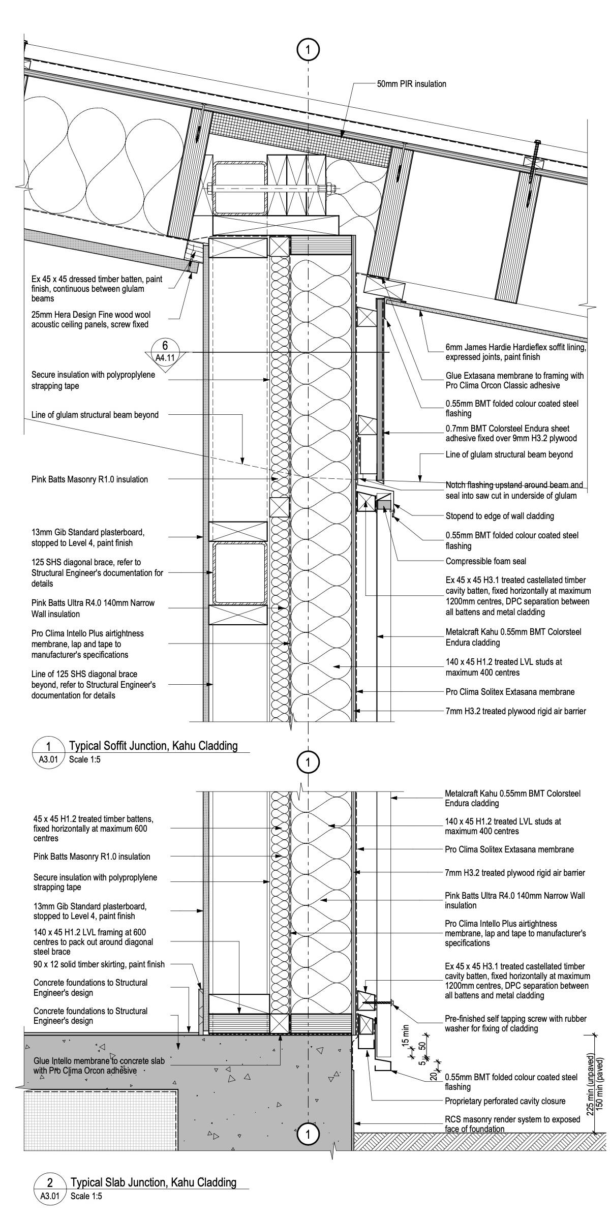
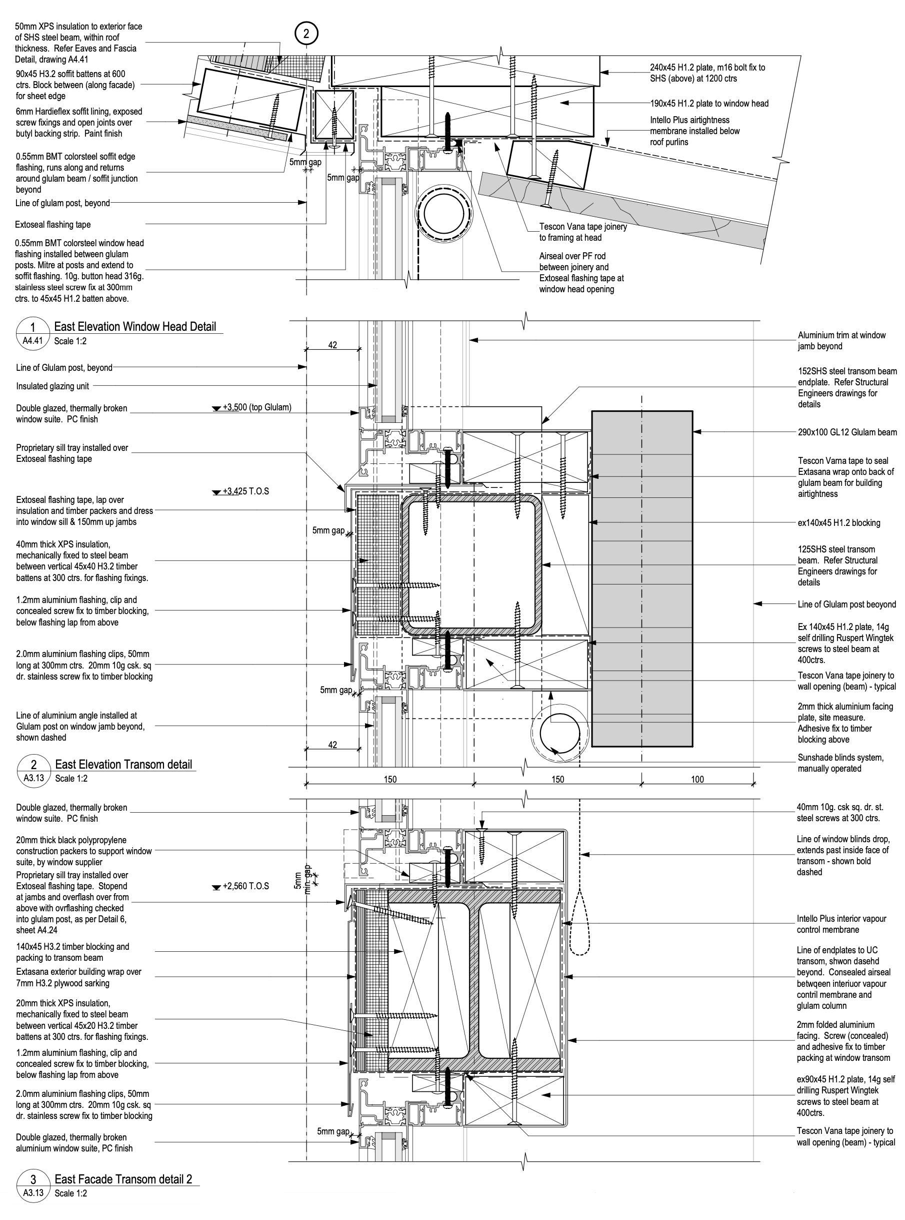
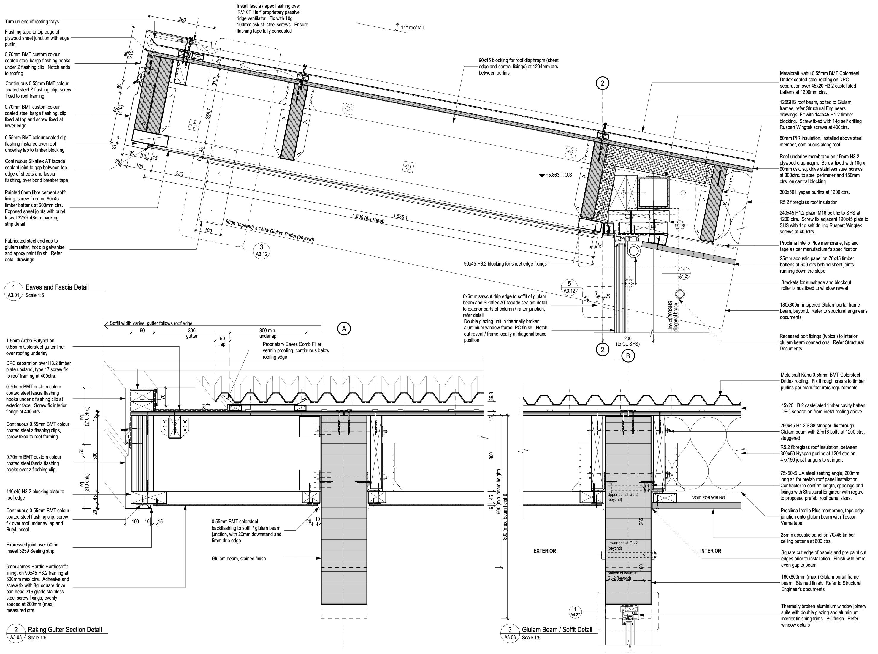
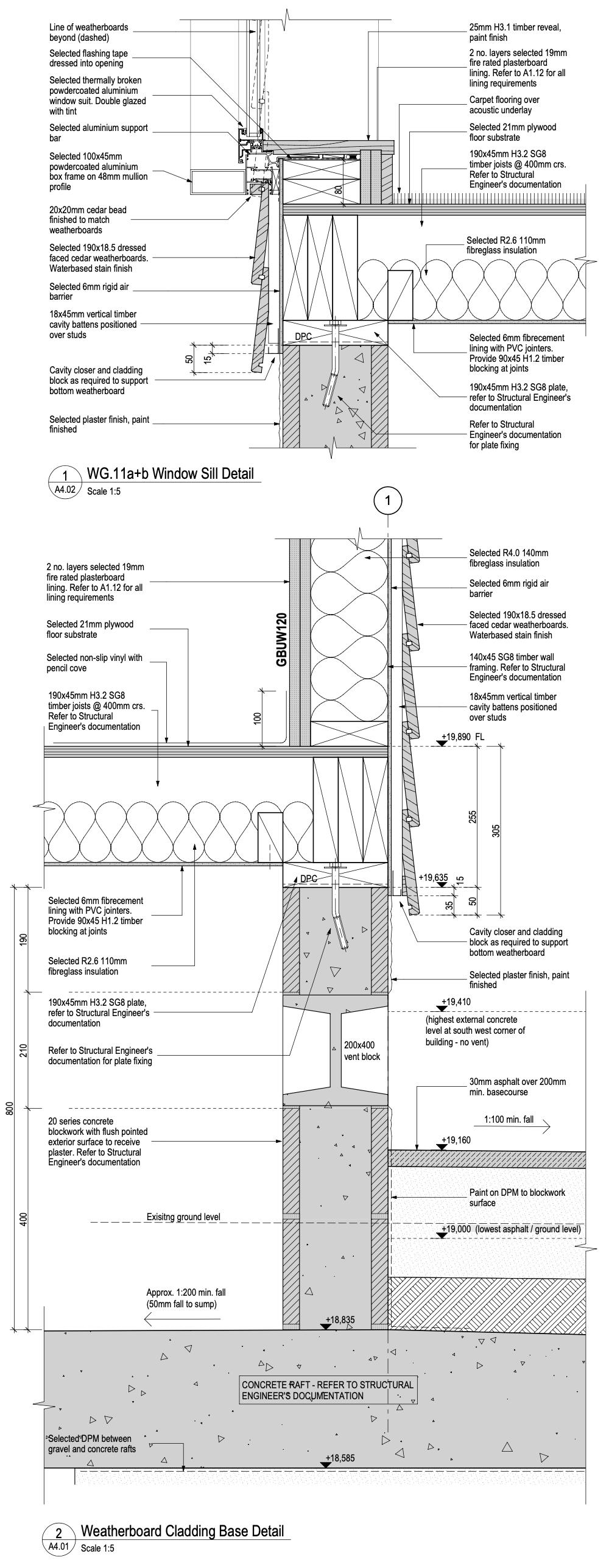
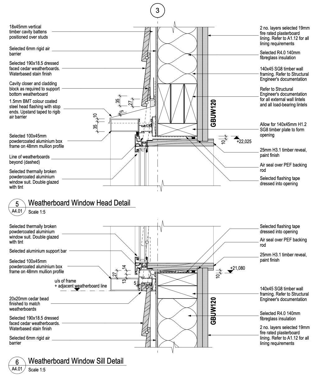
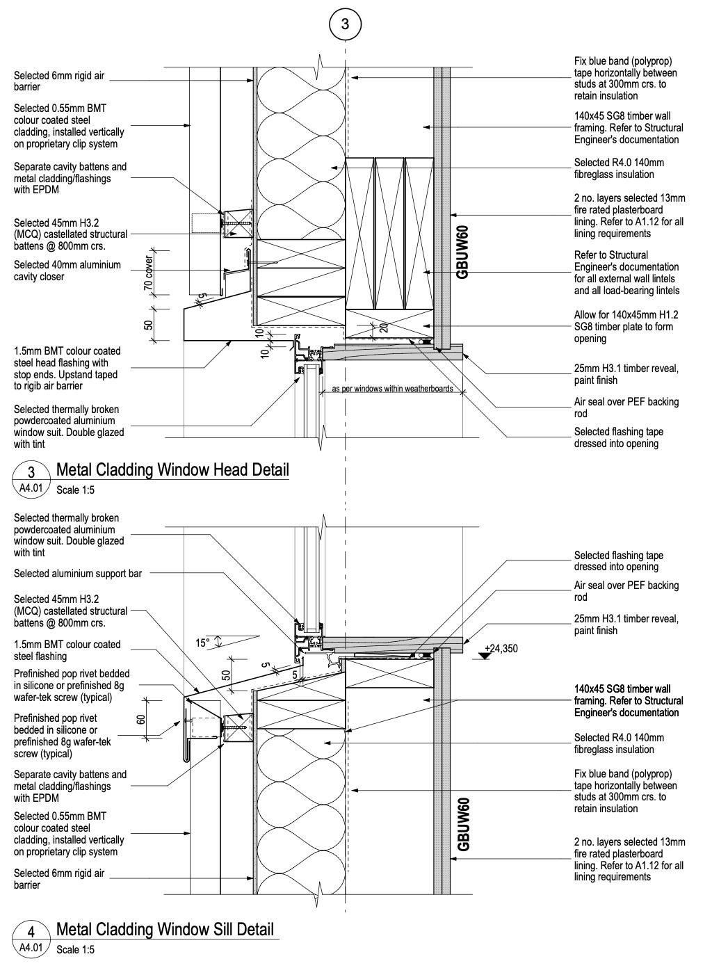
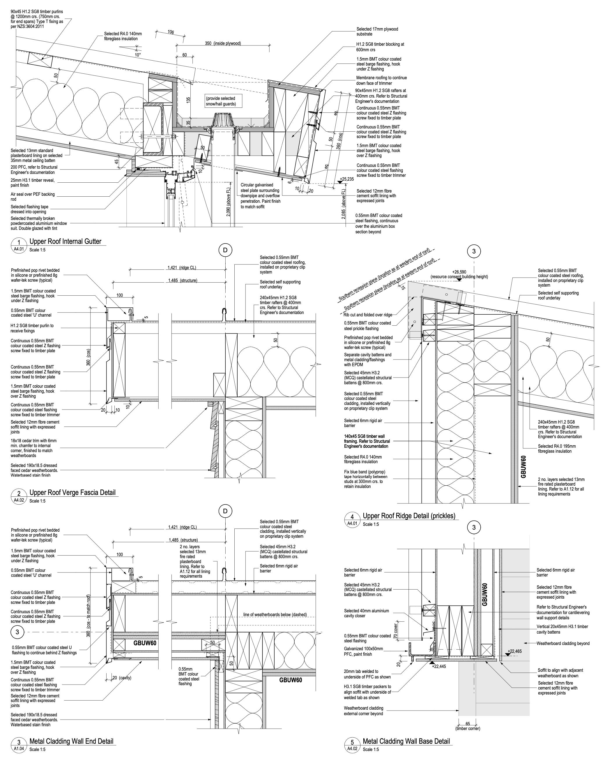
• 2D construction documentation across the project, including grid setout, timber deck structure, floor slab setout, membrane warm roofs, thermally broken doors and windows, and profiled metal cladding.
• Revision management and document control to ensure accurate communication between all stakeholders.
• Key wall and floor slab setout across multiple general assembly drawings.
• Above-ground stormwater calculations and design.
• Supporting the project lead during two phases of value engineering.
• Specification input and completion of several specification sections.


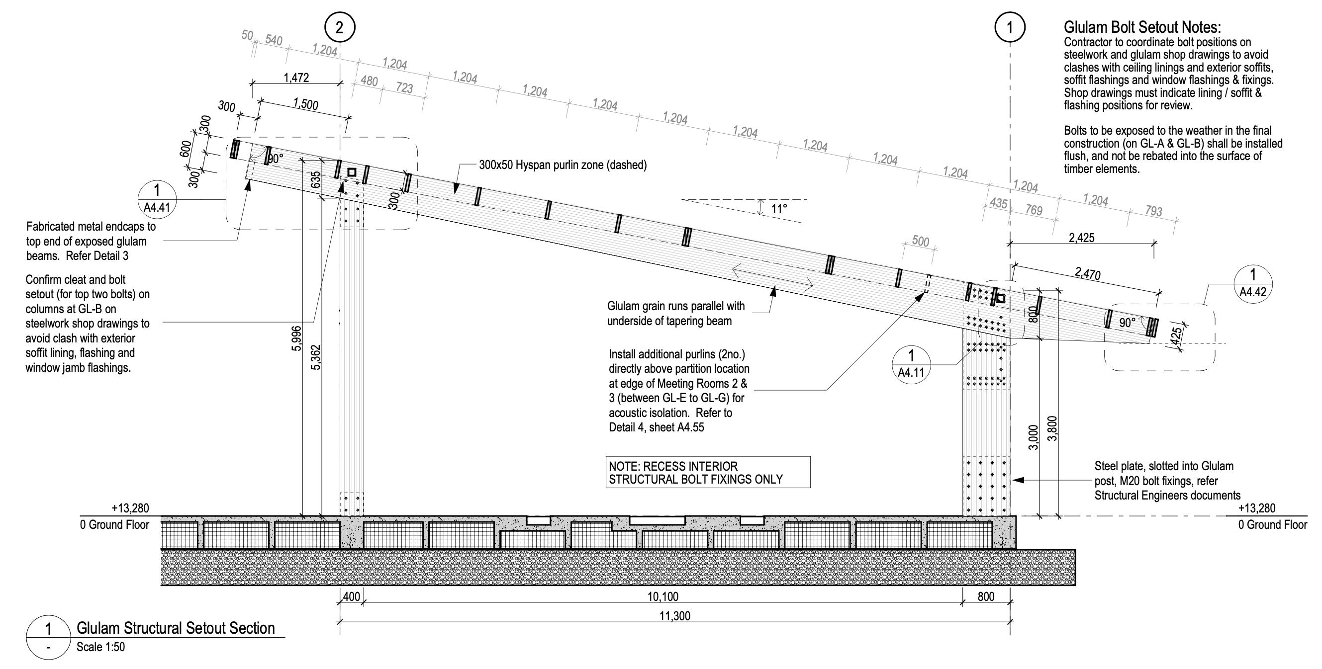
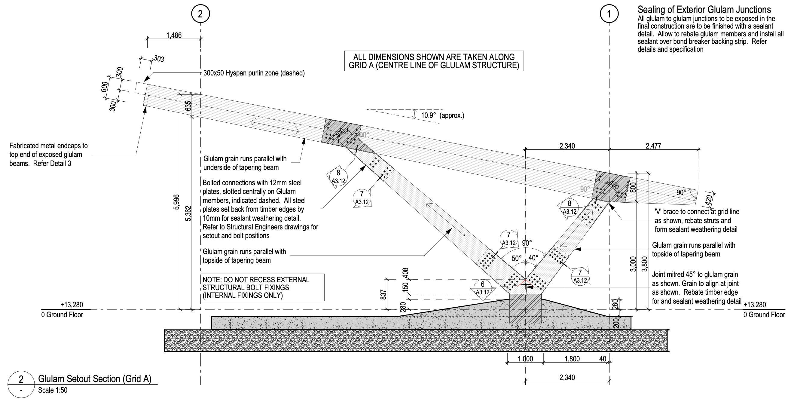
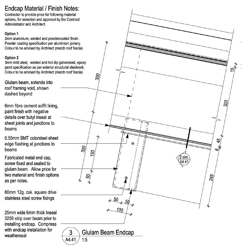
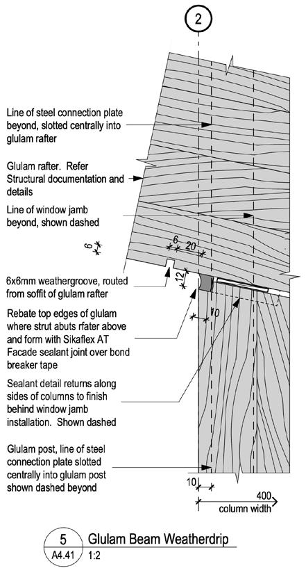
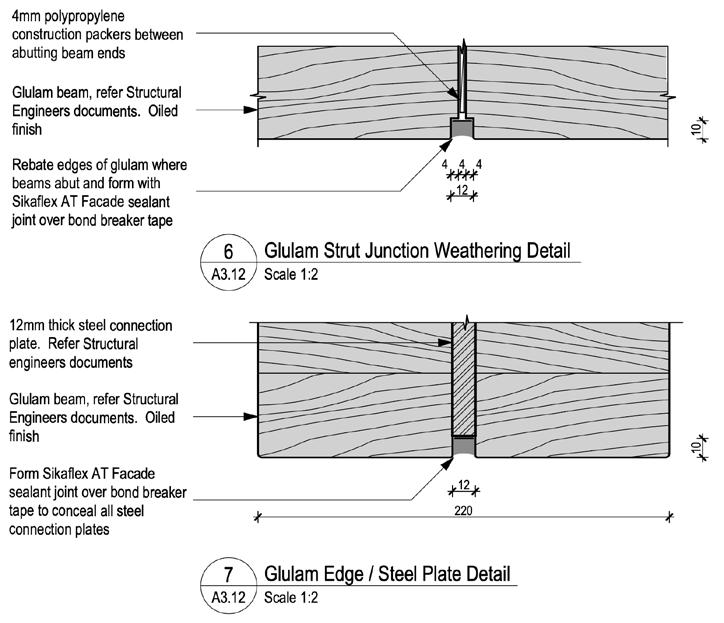
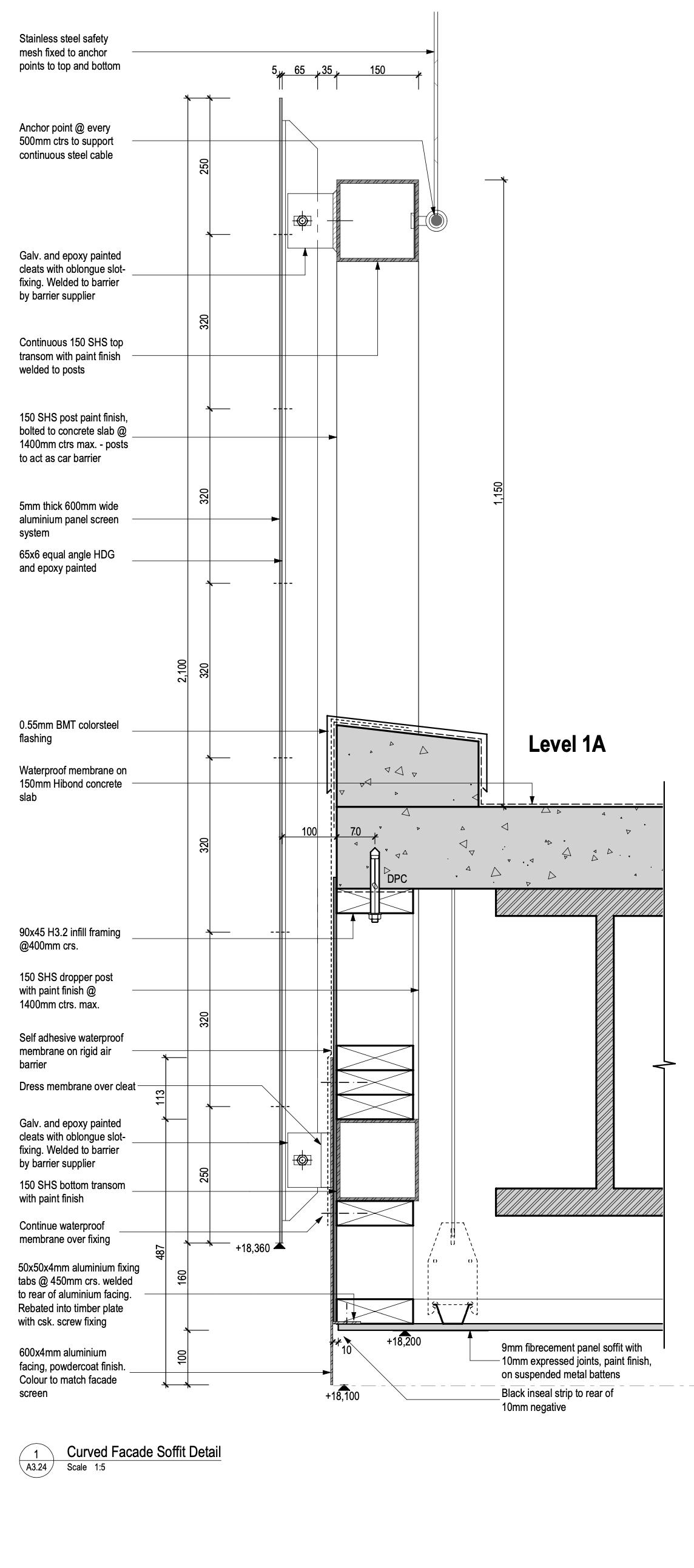
Specifically engineered glu-lam timber structure
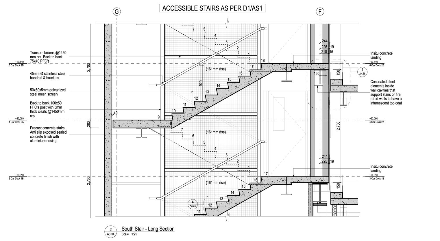
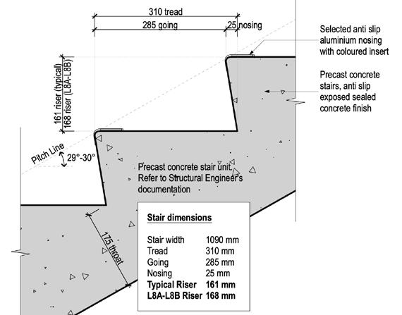
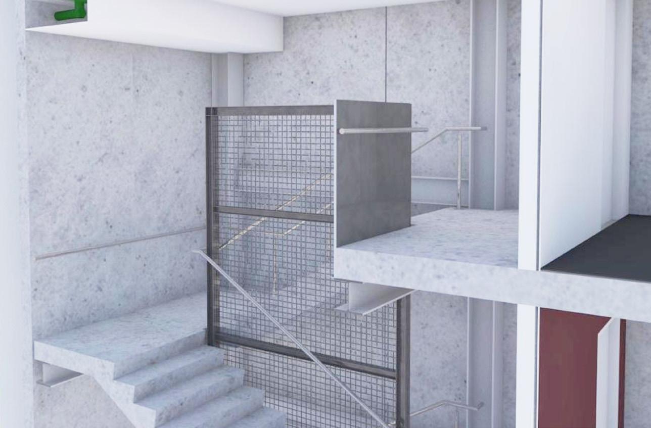
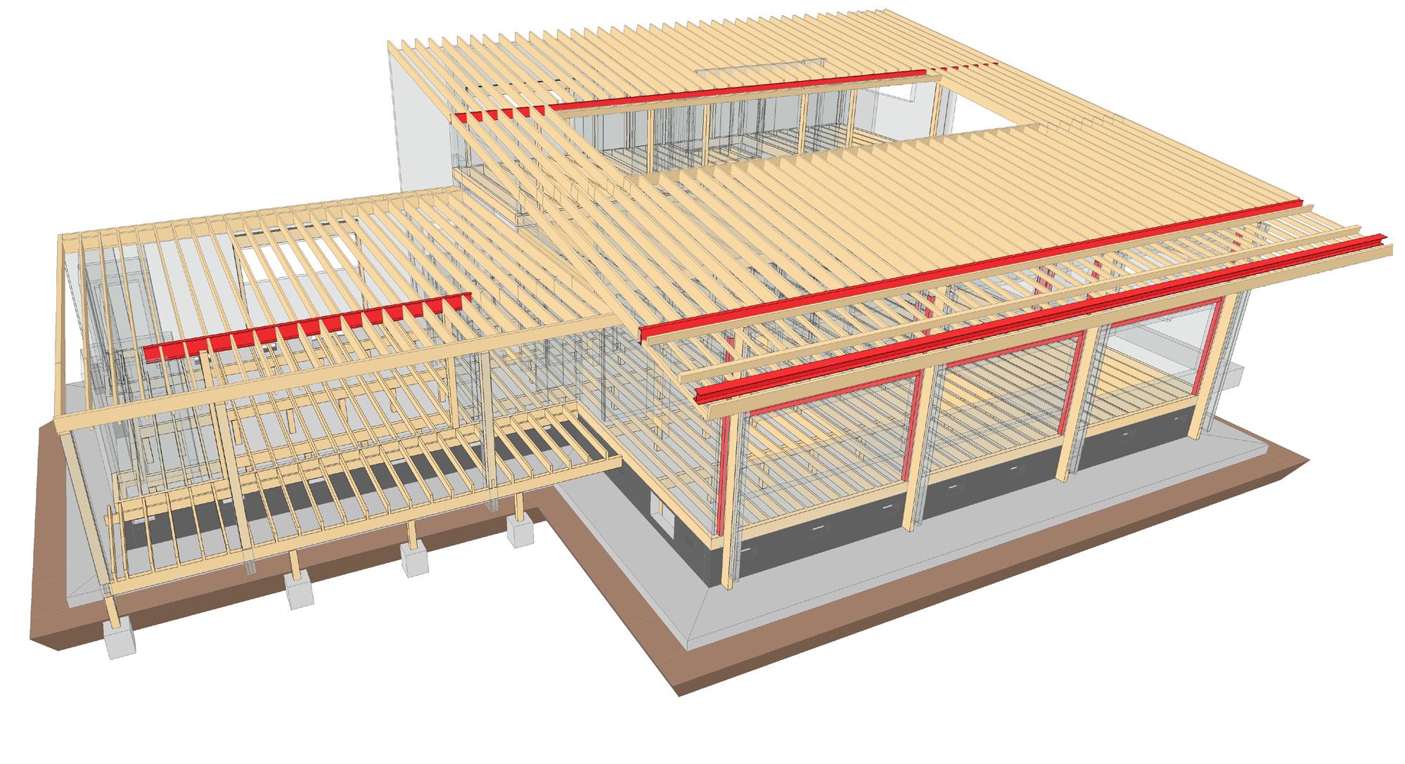
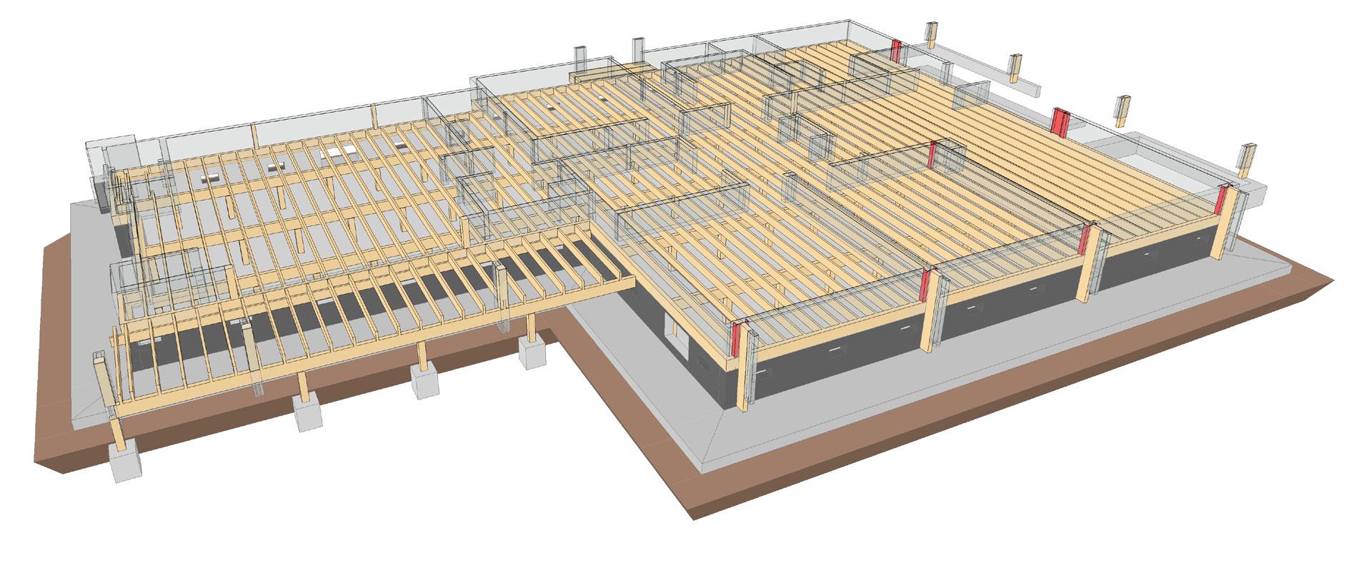
A key feature of the project was the exposed timber structure within the two open plan office spaces. The timber sizes, shapes, grain direction, fixing plates and bolt fixings were all coordinated closely with the structural engineer to achieve the final outcome.
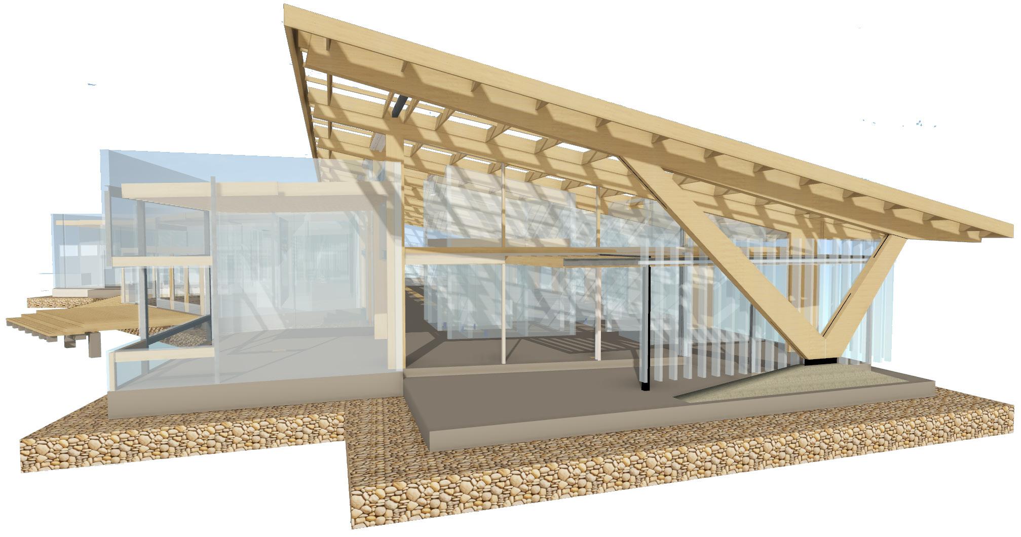
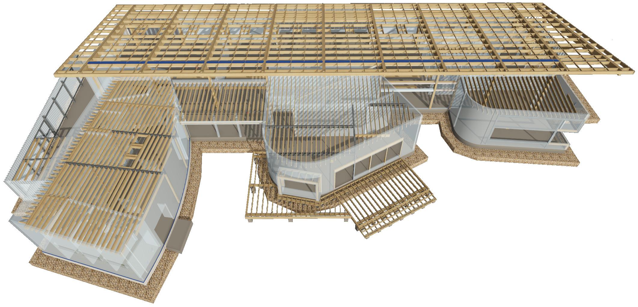
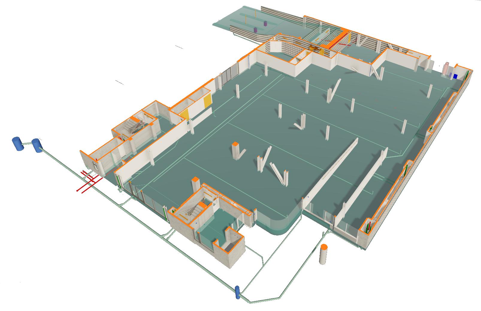
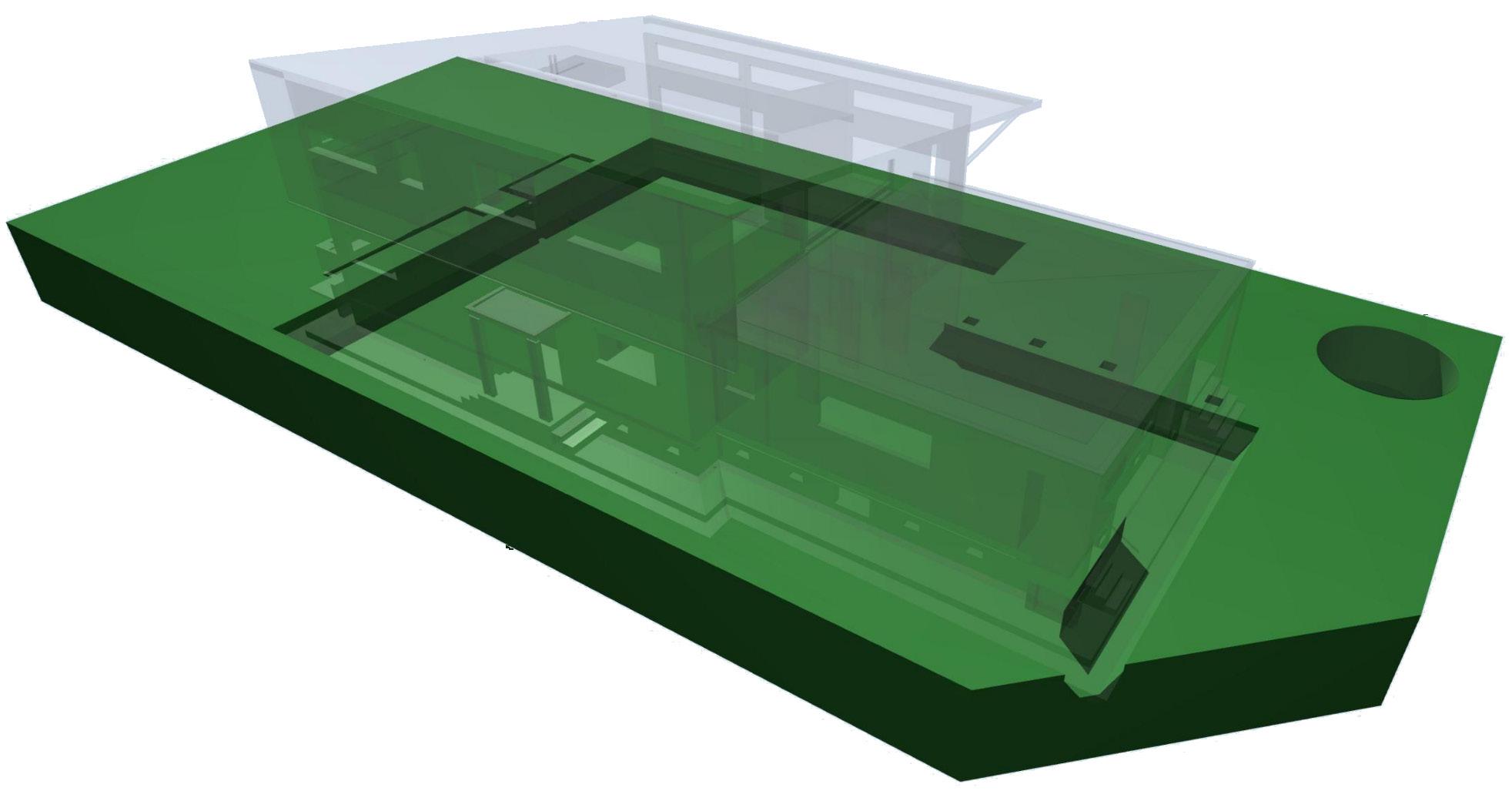
Architectural structure model
In order to both coordinate with the structural engineer’s 2D documentation and to produce our own 2D documentation, a detail 3D model was utilised throughout each project phase. This example indicates all primary structural components as well as the architectural wall locations (blue) and slab rebates / service penetrations. This provided many efficiencies for us during design and documentation

The Terrace Car Park
INFO Type: Car Park and Retail
Place: Central Christchurch
Year: 2019 - 2020
Client: Gough Family
Roles: Architectural Technician
Architectural BIM Manager
Document Controller
Phase: Working Drawings
Building Consent
Observation
DESCRIPTION
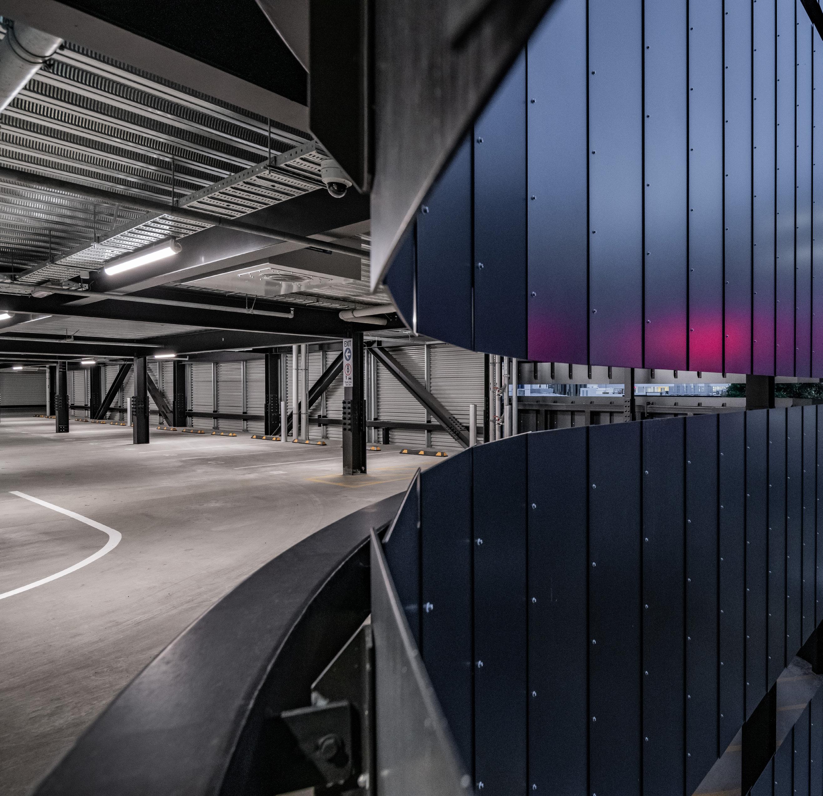
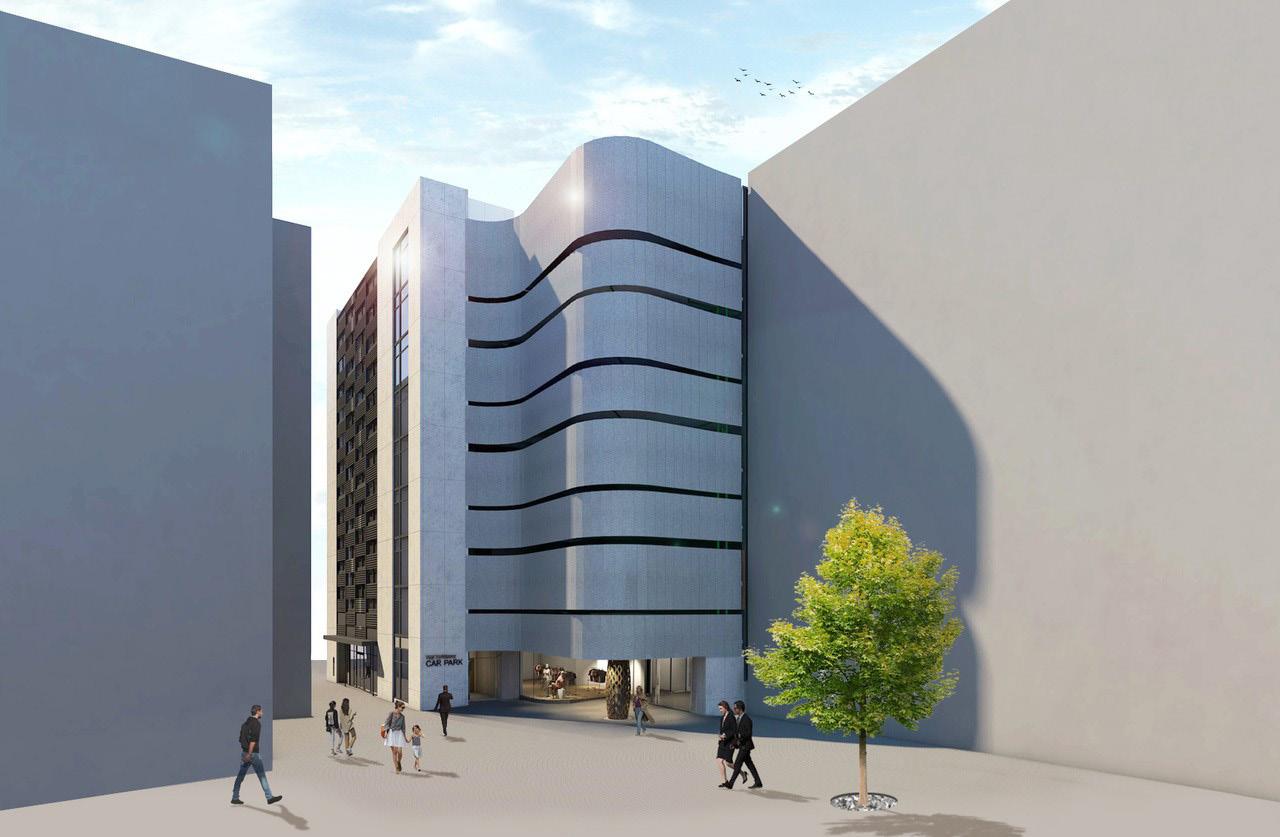
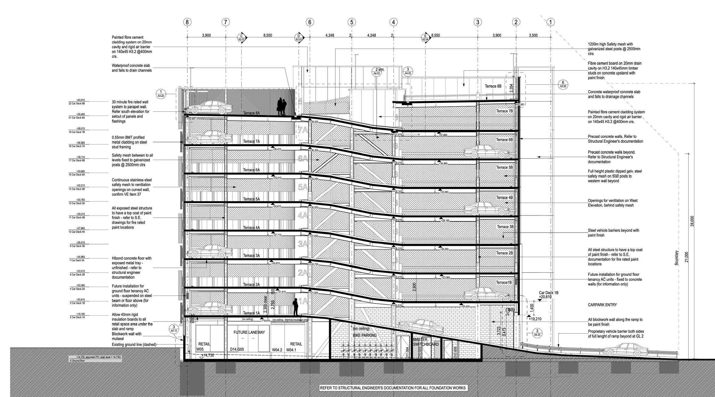
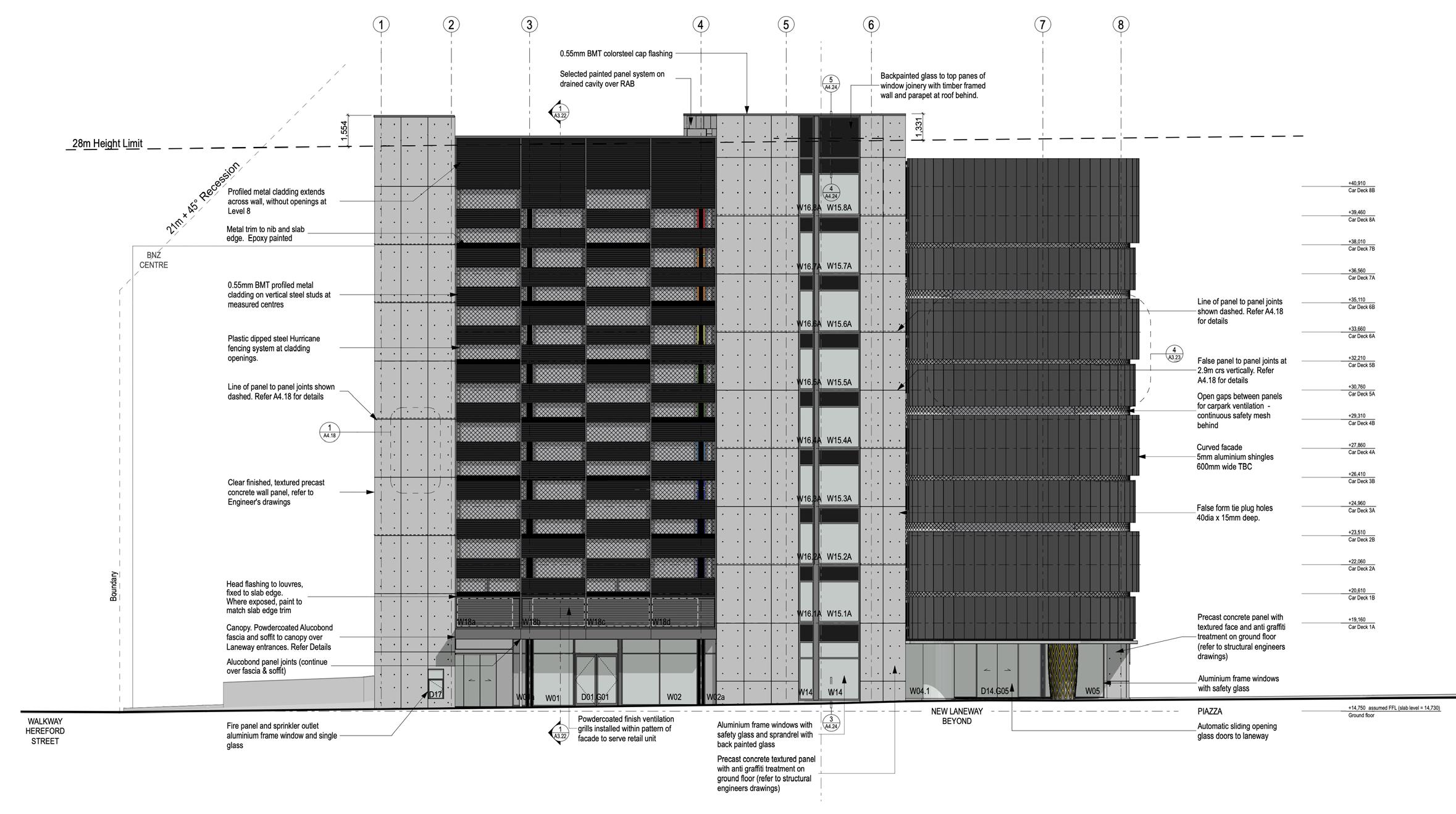
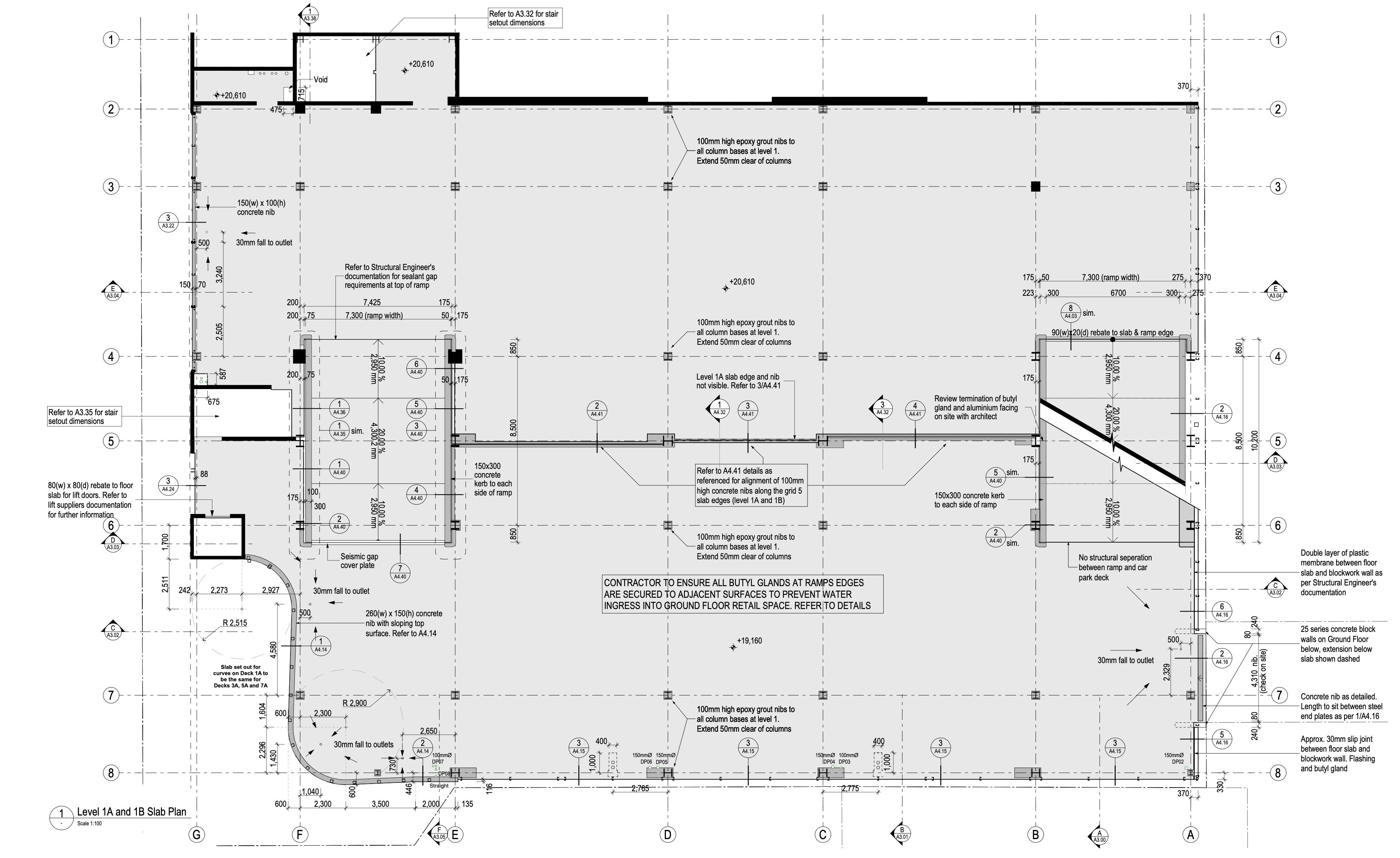
This completed project provides 8 levels of new central city car parking (440 car parks in total) sitting above 1220m2 of ground floor retail space, as part of the Gough Family’s ‘The Terrace’ Development.
The ground floor retail areas face onto the new Shands Lane and The Terrace piazza, with the inclusion of a pedestrian laneway linking to the neighboring BNZ Centre. The car park can be accessed via the car ramp entry off Hereford Street and also via the stair and lift cores located off the laneways.
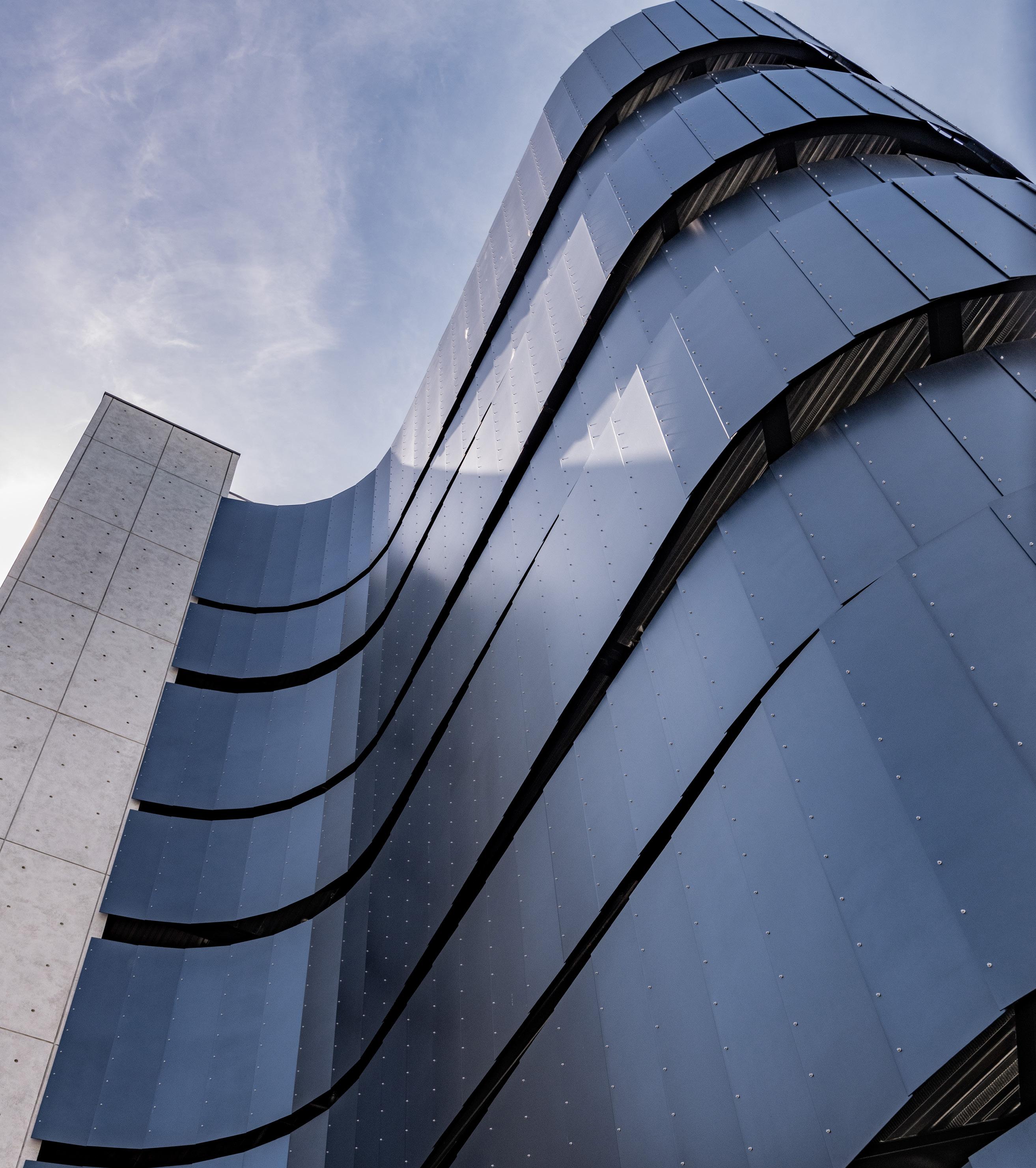
The exterior is highlighted by a black curvaceous exterior feature facade that has been inspired by the black eels that inhabit the Avon River nearby. With black intumescent painted steel and bright colour coding of each floor, the carkpark levels have a very striking appearance.
The car park is future proofed with the provision for large scale EV charging capacity and the inclusion of secure bicycle parking on the ground floor.
RESPONSIBILITIES
• Collaborating in-house with the project lead and two to three other architectural technicians.
• Extensive coordination with the structural engineer given the high reliance on the steel primary structure and pre-cast concrete on the project.
• Coordination with the various MEP and Fire Engineering teams throughout documentation and construction.
• Precast concrete and steel fabrication shop drawing reviews during construction.
• OpenBIM collaboration with various design consultants.
• Archicad file management.
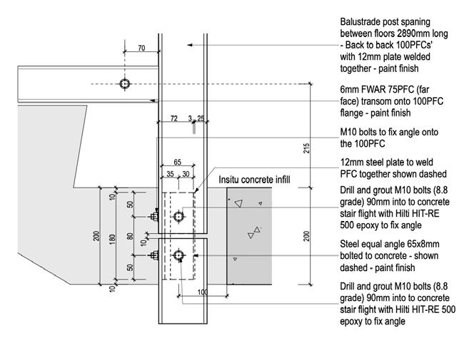
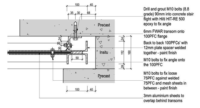
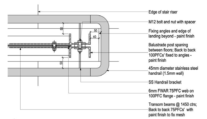
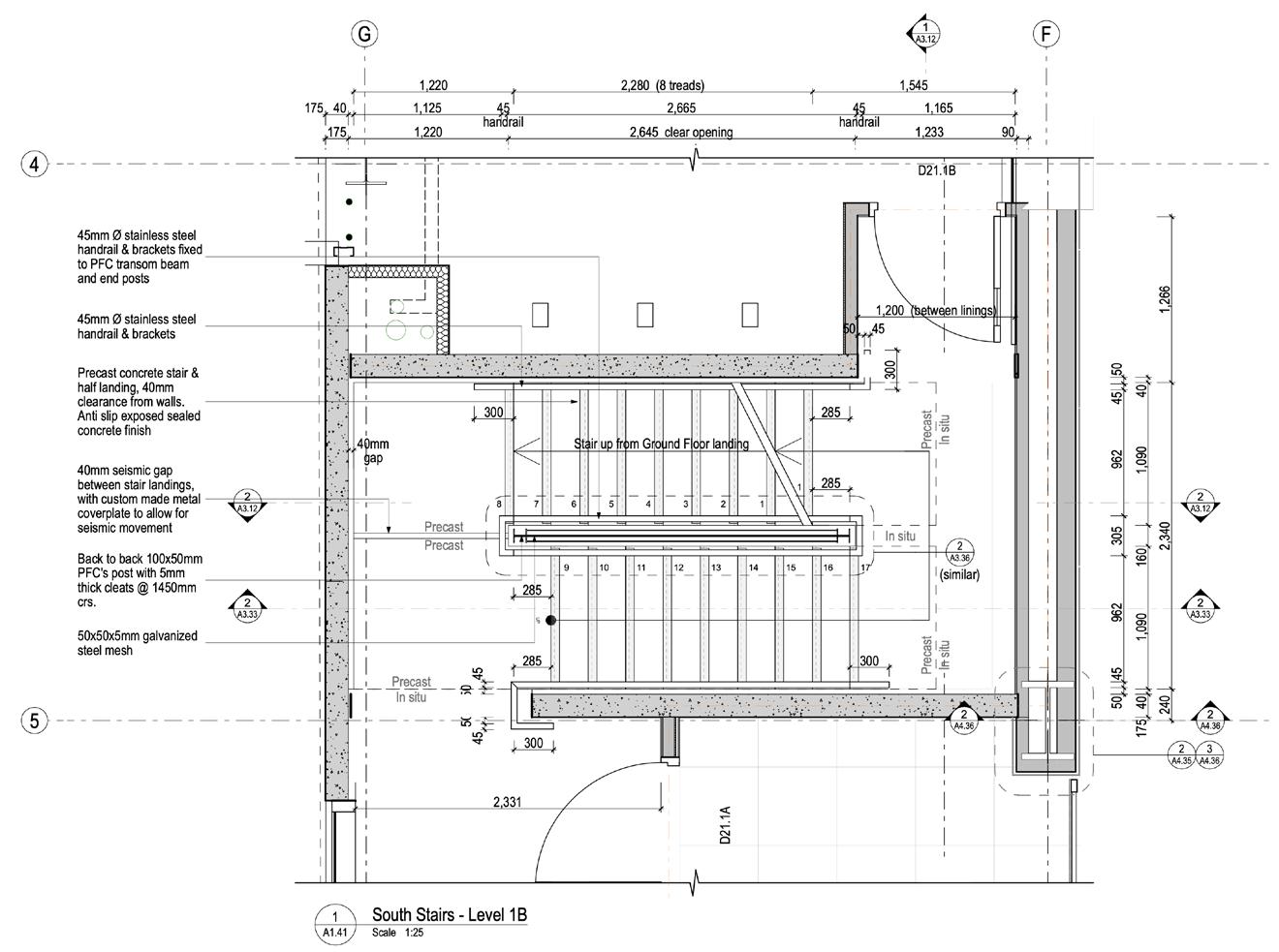
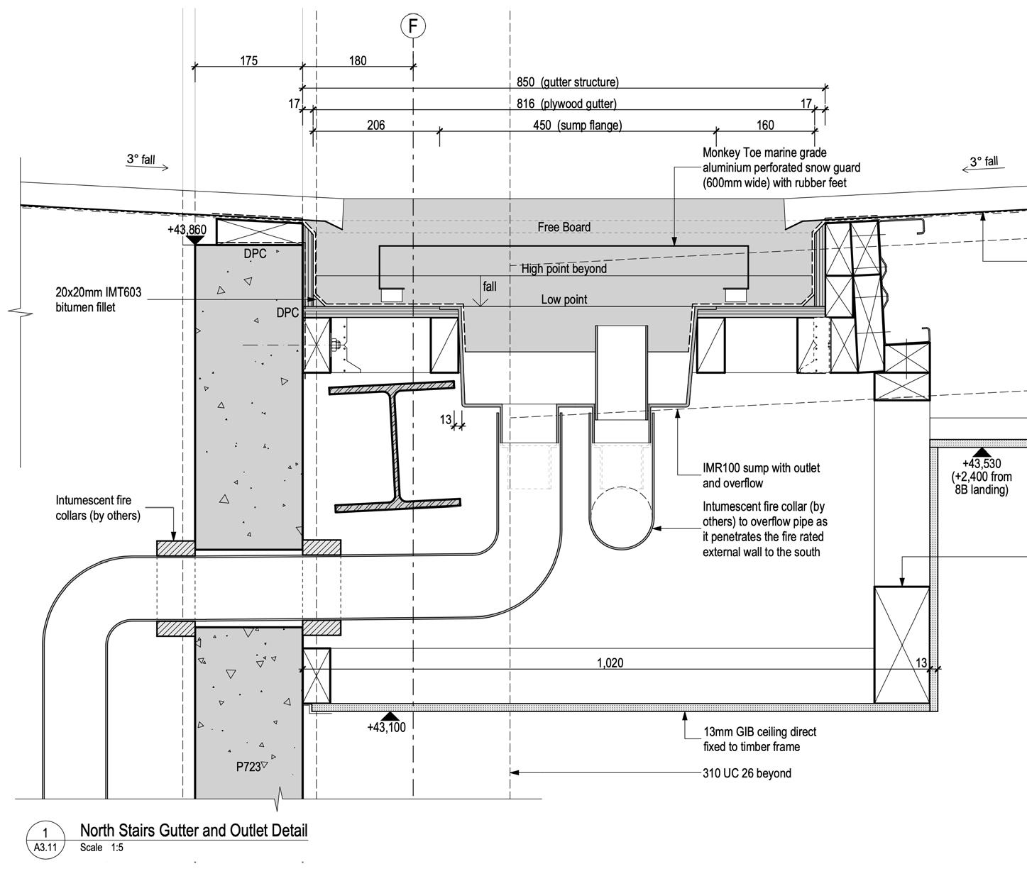
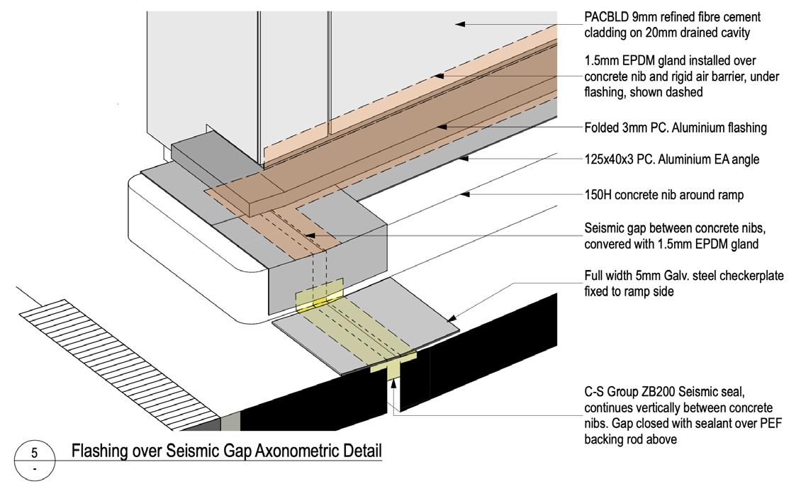
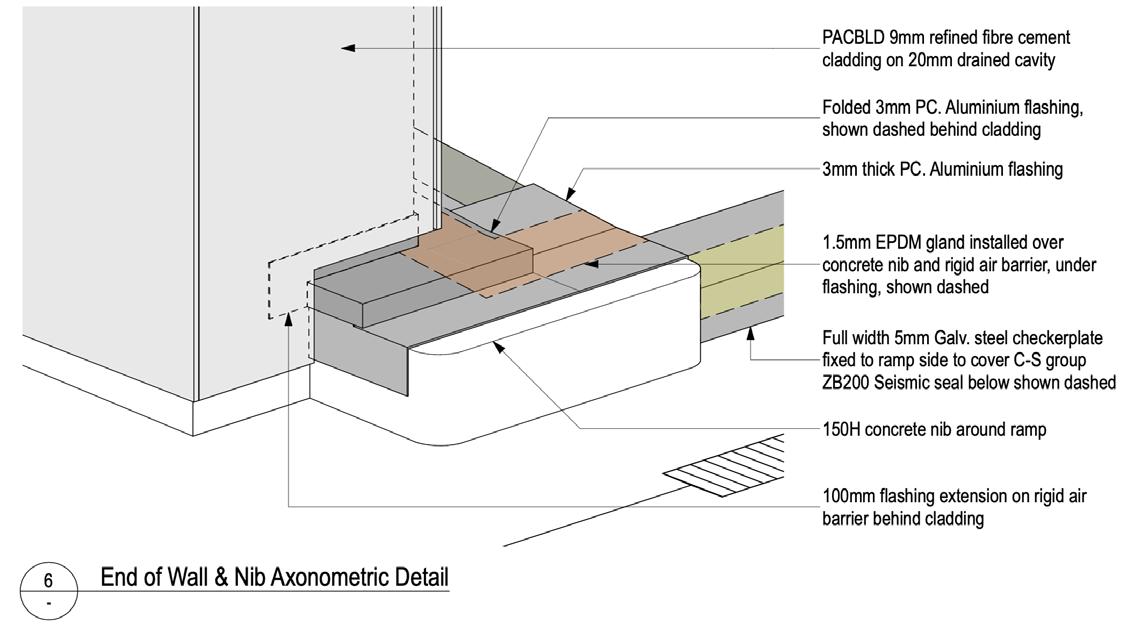
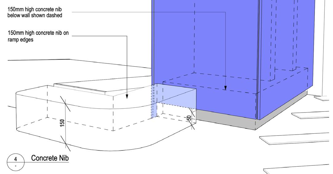
• 2D construction detailing across the project, including floor slab setout, lift and stair core membrane roofs, profiled metal cladding details, precast concrete joints, eastern laneway entry and associated screens to the levels above, cover plates to ramp movement joints, and internal stair setout and detailing.
• Above ground stormwater design and documentation, including steel and concrete penetration coordination with the structural engineer.
• In-house revision management and document control to ensure accurate communication with all stakeholders.
• Supporting the project lead in preparing all building consent documentation.
Opposite page: The black ‘Eels’
This curving powder coated aluminium panel system sits above the main pedestrian entrance. To the left is the precast concrete stair and lift core
Developed Design
As shown in this image, the design and detailing needed to consider any and all existing and future developments surrounding the site.
Previous Page: ‘Level F’
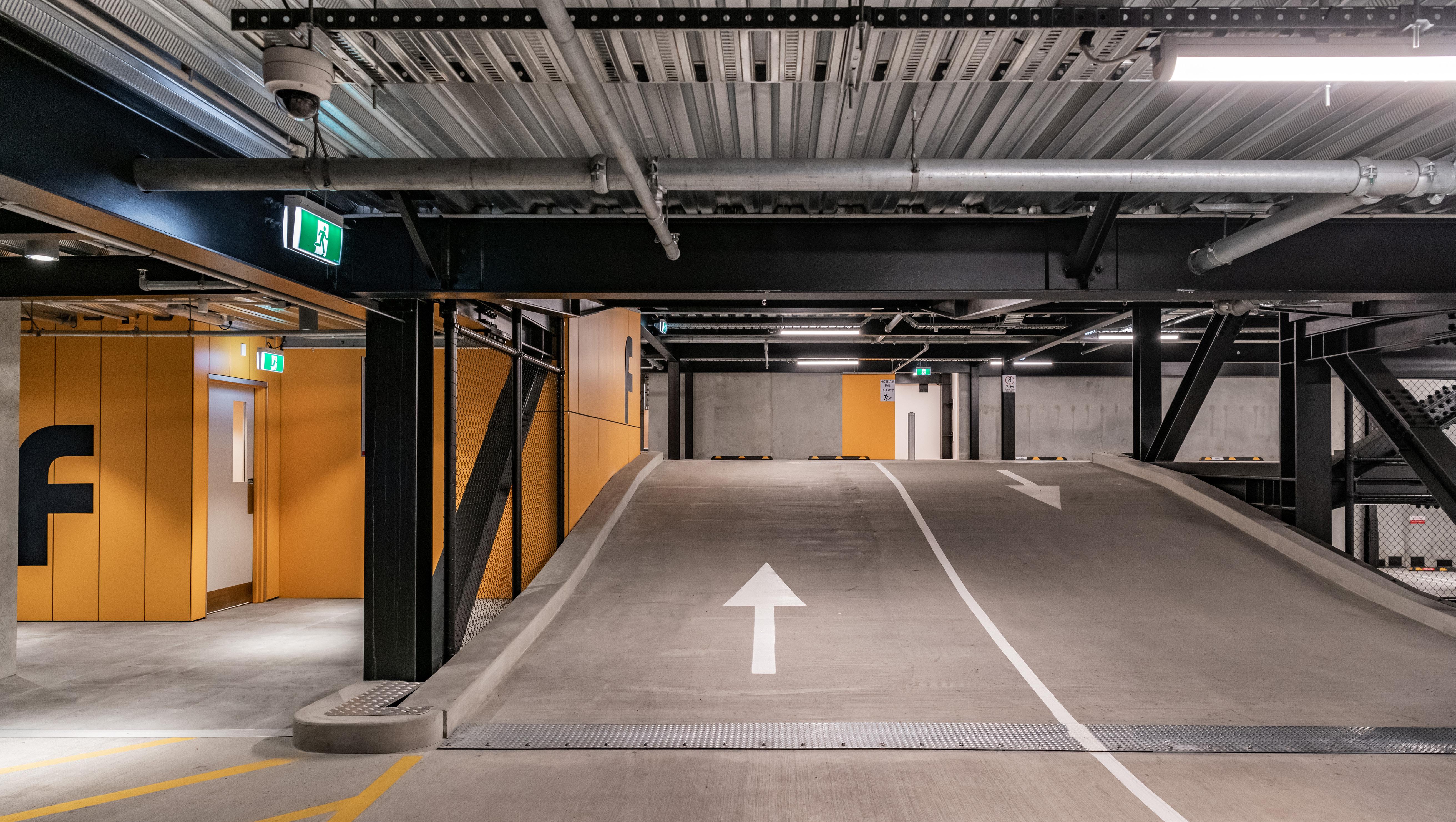
This photograph shows the typical relationship between the main stair and lift core to the left, and the two-way carpark ramps between each level.
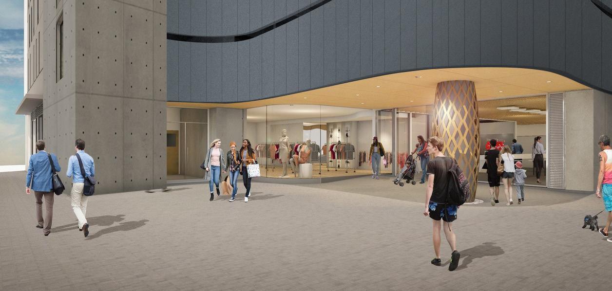
Ground floor retail
The project included all base build items to the ground floor, while leaving the internal space open for future tenancies (now occupied by Timezone and other small tenancies.
Western facade facing the rear of the wider Terrace development
North - south cross section through the carpark entry ramp
All steel fabrication drawings and models were initially reviewed by myself, with further high level checking completed by the project lead also. Shop drawings for all in-situ and pre-cast concrete panels were a part of the overall review process as well.
Although we were not engaged to provide full coordination of the building services, we did federated the BIM modes in-house to review any architectural impacts during the design phase. The services included MEP and fire, with further reviews completed of sprinkler pipe shop drawings during construction.
Federated BIM model Ground Floor
Federated BIM model
Federated BIM model
Typical car park level
Structural fabrication

PANETTONE
HORIZONTAL JOINT
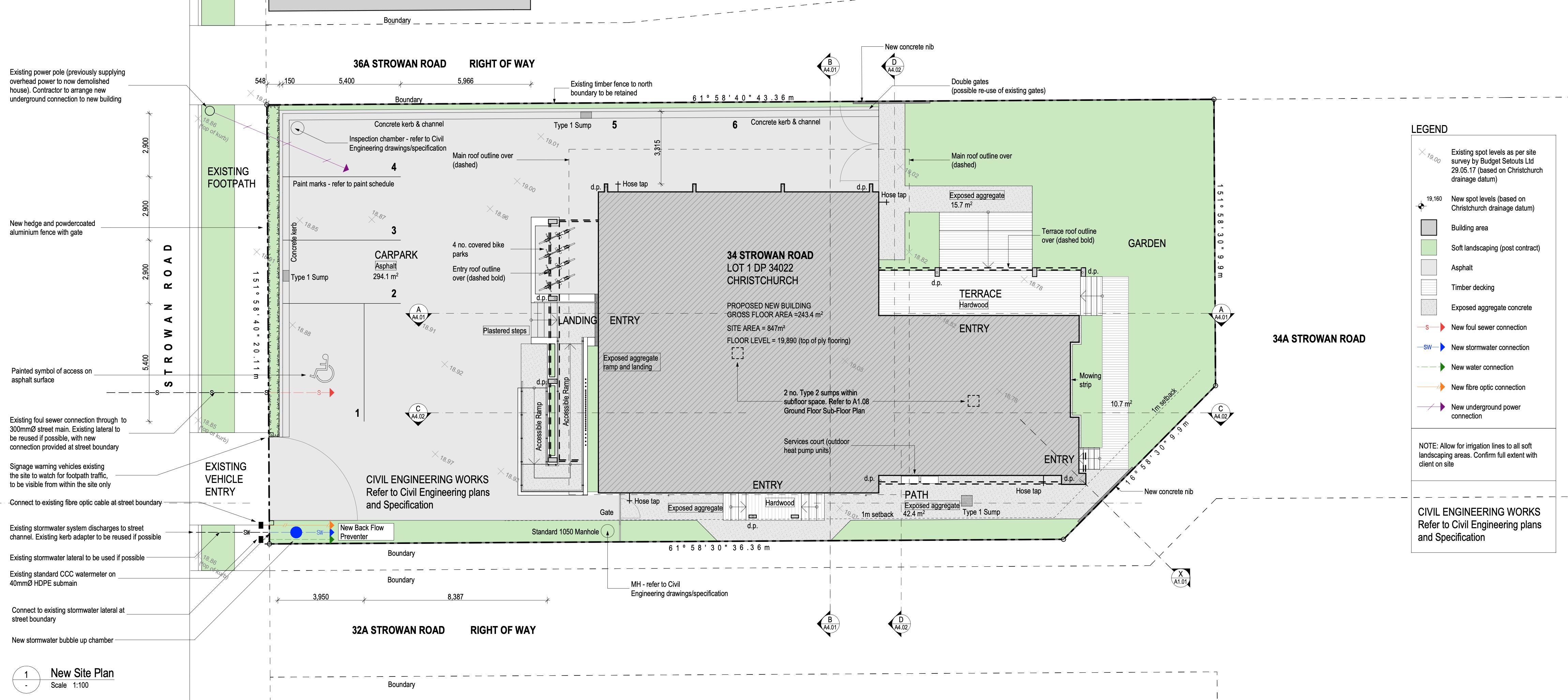
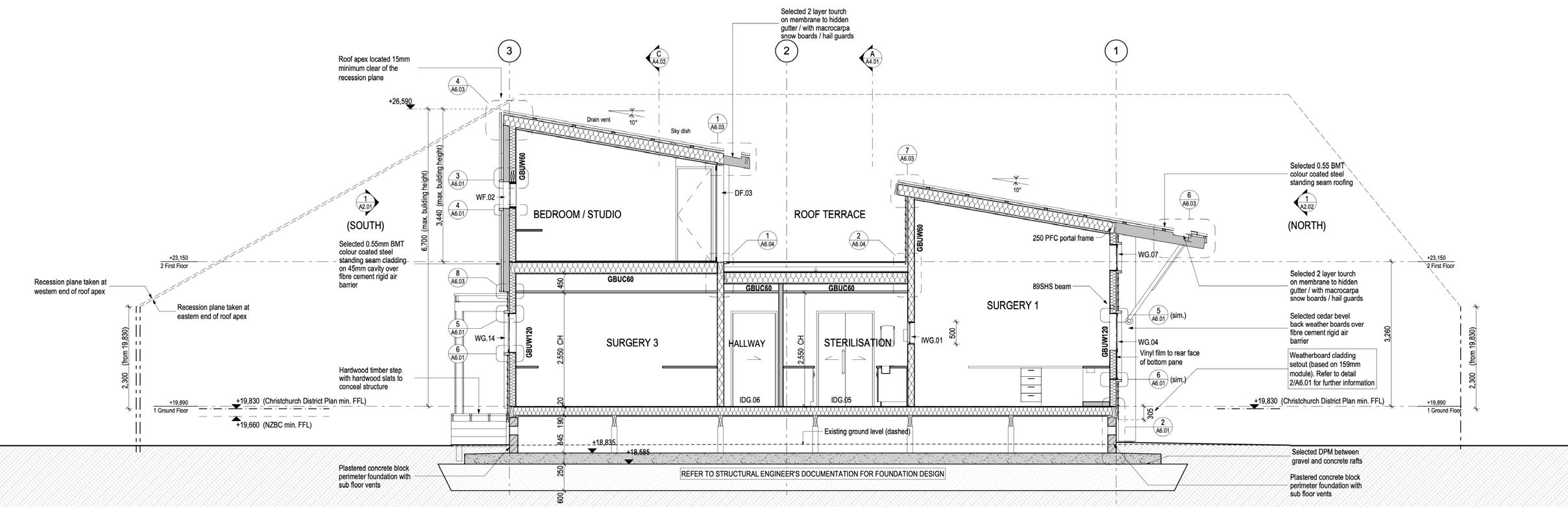
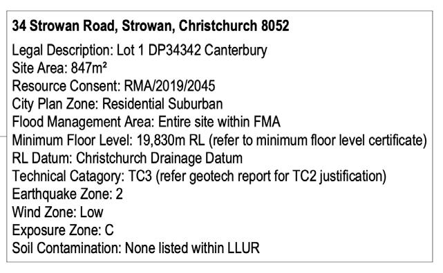
Strowan Road Orthodontist
INFO Type: Orthodontist Office
Place: Strowan, Christchurch
Year: 2018 - 2023
Client: Mark and Sonya Kum
Roles: 2IC / Project Lead at times
Architectural Technician
Architectural BIM Manager
Document Controller
Phase: Developed Design
Resource Consent
Working Drawings
Building Consent
Limited Observation
DESCRIPTION
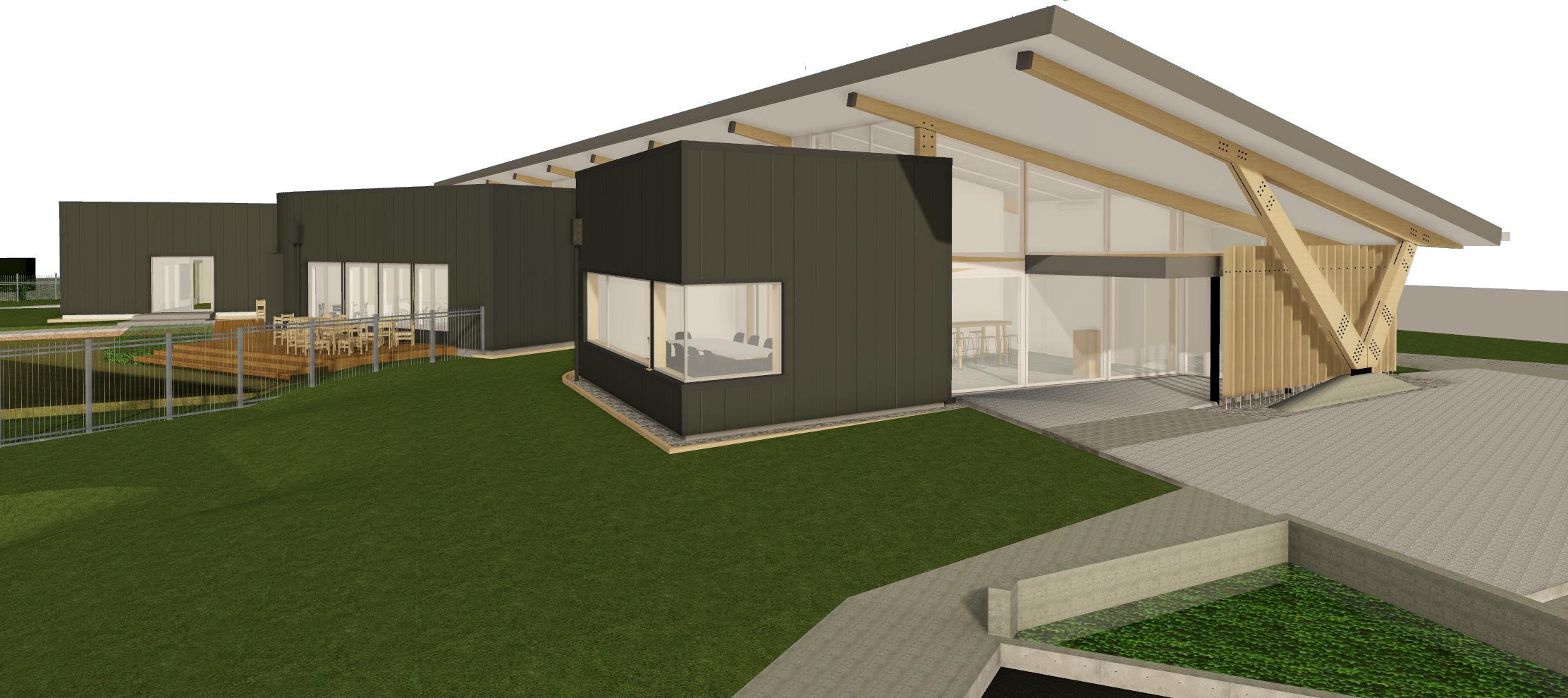
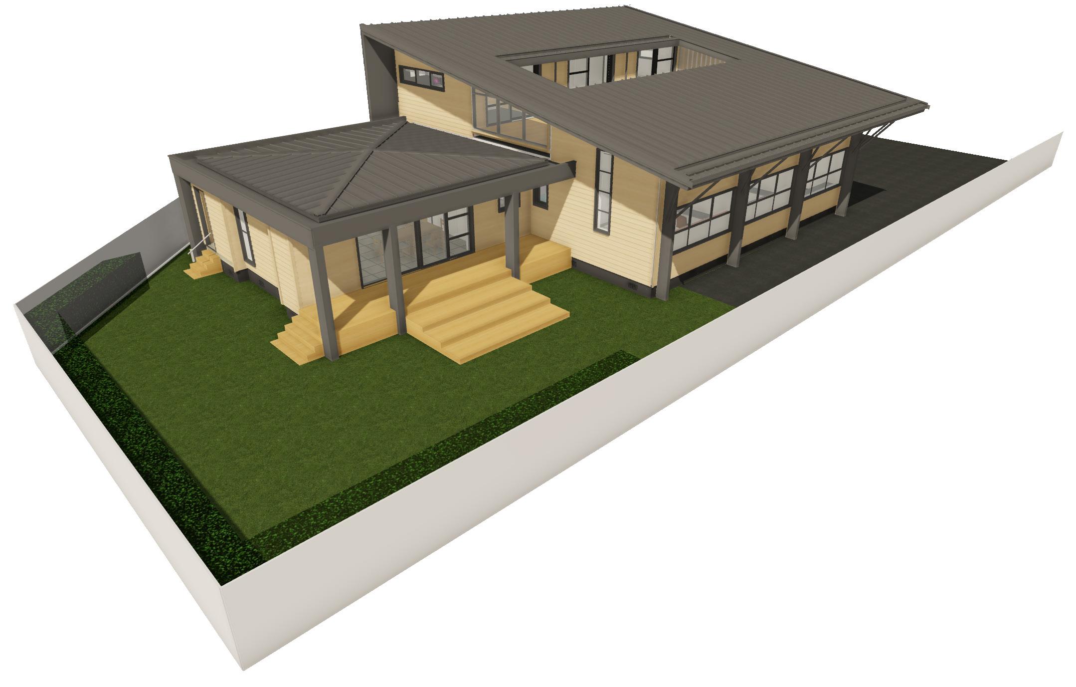
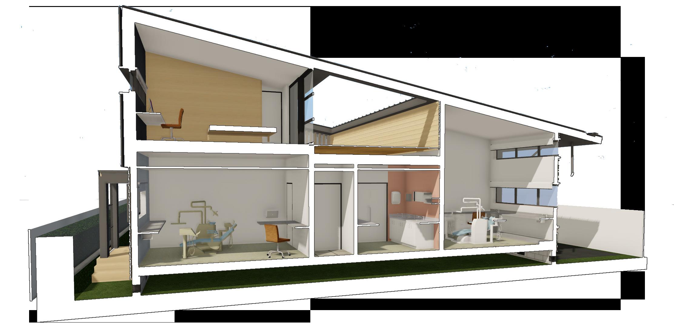
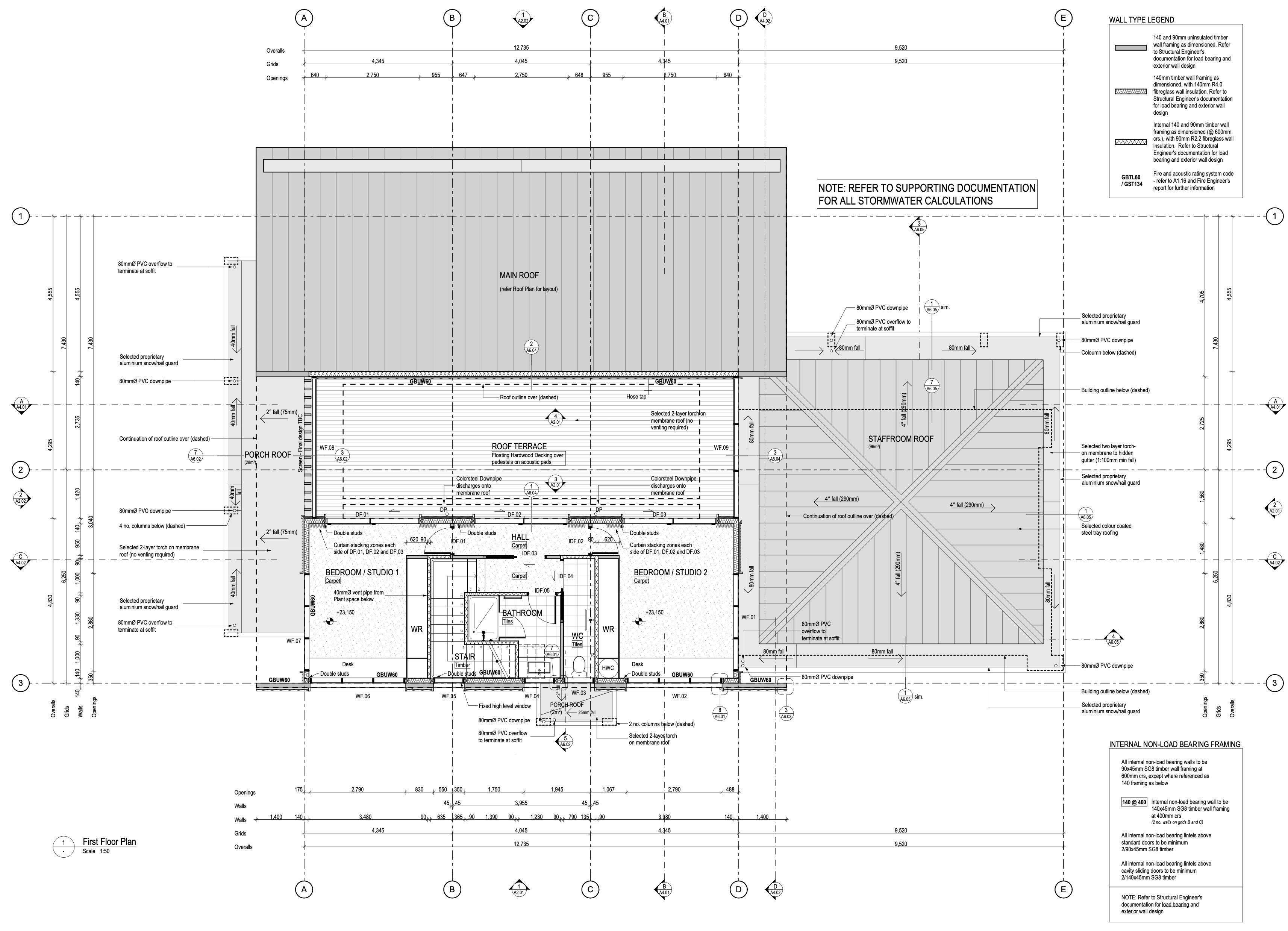
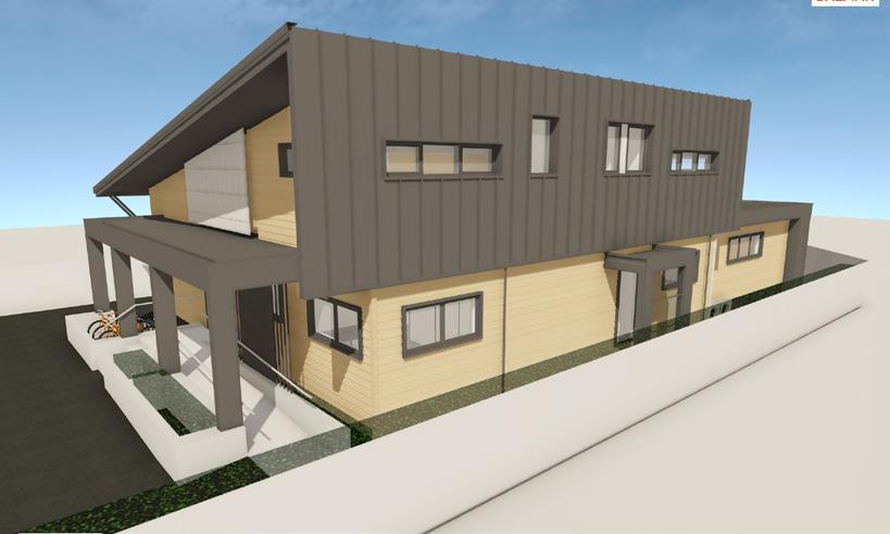
This new development for a new privately run orthodontic practice includes three new surgeries and supporting facilities on the ground floor, with two residential sleeping studio areas on the first floor. A staffroom wing also protrudes into the rear garden facing away from the road. Future post-retirement plans will possibly see the development become the client’s home.
Due to it’s location and site proportions, several complexities arose during concept and developed design which required very specific resolutions. These complexities included liquefaction risk, flooding risk, potential stormwater runoff to adjacent properties, as well as risks associated with fire safety due to the proximity to the boundary and the need for sleeping spaces above a commercial operation.
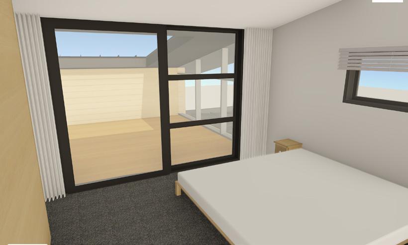
An enclosed first floor balcony provides a space sheltered from the wind and street, while providing light and outdoor access for the first floor spaces.
The exterior cladding comprises of lightly white-stained cedar cladding, dark colour coated steel tray roofing and fibre cement cladding painted to match.
Construction is due for completion in 2024.
RESPONSIBILITIES
• My main responsibility was to drive the developed design process with the client and project architect, followed by the architectural drawing documentation and coordination with the structural and fire engineers.
• Coordination with the town planning consultant with regards to building envelope, site excavations and resource consent application (lodged by the planing consultant).
• Archicad file management.
• 90% of all structural setout and construction detailing.
• 90% of all general assembly drawings.
• Door and window schedules.
• External cladding selection and specification.
• Above ground stormwater calculations and design.
• Extensive BIM modeling for visualisation and architectural documentation production which played a key role in the projects success.
• Facilitating client model reviews utilising BIMx to assist in project phase signoffs from developed design onwards.
• Revision management and document control.
• Completing and compiling all documentation required for building consent, including wind zone, topography, durability and H1 assessments.
• Supporting the project lead during construction contract negotiations.
Opposite page: Architectural BIM model
This was presented to the clients within BIMx during each developed design review session and before phase sign-off.
• Providing limited observations services during construction on an ‘as needed’ basis. Namely for structural steel and aluminium window joinery shop drawing reviews and other miscellaneous queries.

Staff Kitchen
Staff Room
Reception and Waiting Room
Upstairs Bedroom Studio
Strowan Road Entry
Southern Elevation
Rear Garden with Kitchen wing
Roof Terrace
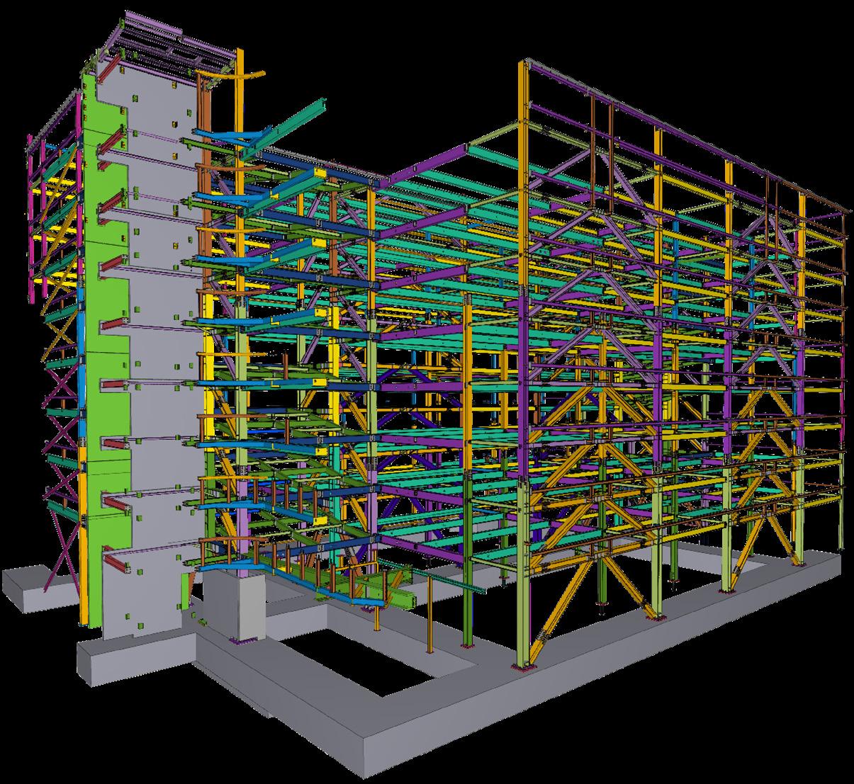
Architectural structure model
All steel and timber structural members were designed by the client appointed Structural Engineer, including member sizes, centres and connections. A structural model was produced by ourselves in order to document the setout of all structural elements, and to ensure that all 2D floor plans and sections that were extracted from the model were showing consistent information. This model was also used for steel fabrication reviews and client communication.
Foundation design
A unique foundation design was required for this project given the potential for liquefiable soils, the city council flood management zone (minimum floor height requirements) and the client’s requirement for an accessible subfloor space. Extensive coordination was required with the Structural Engineer to finalize the levels of the gravel raft, concrete raft and vented blockwork perimeter foundation.
Excavation of soil
To show compliance with the townplanning requirements and resource consent, we were required to provide the volume of soil to be removed. This was best done using the model geometry.
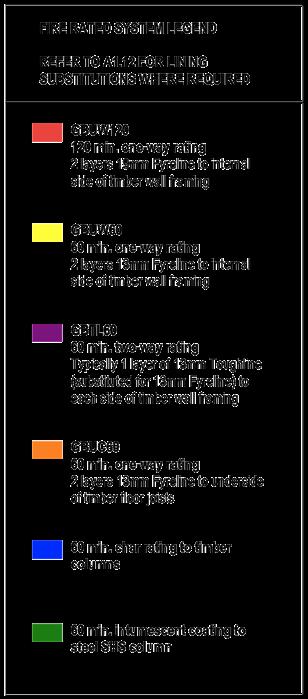
Passive fire design
Passive fire ratings were required throughout the project due to the proximity to boundaries and the sleeping spaces above the commercial spaces. Embedded data within each key modeled element allowed us to extract this data in 3D graphical form, as well as in 2D text on the general assembly drawings.
Building envelope
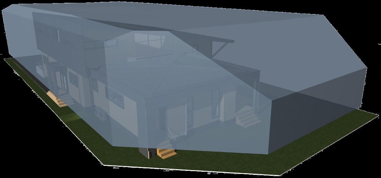
To show compliance with the townplanning requirements and resource consent, a building envelope model was produced using proprietary modeling tools. This demonstrated the location of all building setbacks, all recession planes and the maximum building height, while confirming that no envelope penetrations were present.
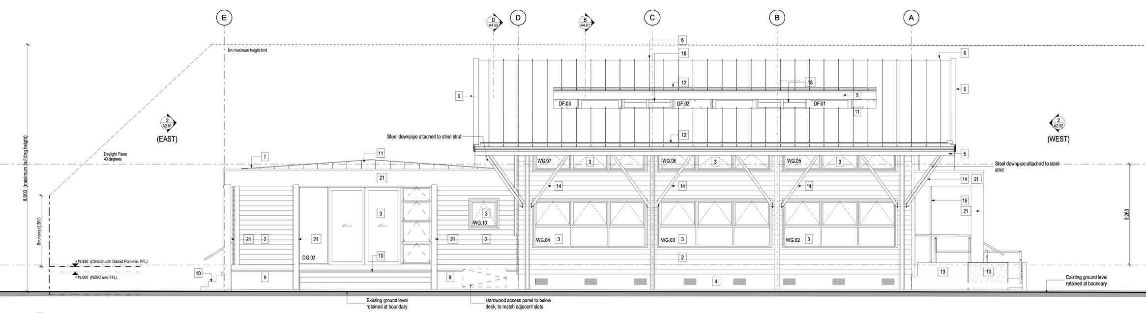
North Elevation
The Salvation Army
INFO Type: Religious Centre
Place: Central Christchurch
Year: 2008 - 2017
Client: The Salvation Army
Roles: Architectural Technician
Phase: Concept Design
Developed Design
Working Drawings
Building Consent
DESCRIPTION
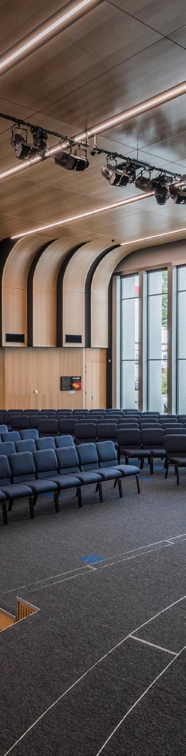
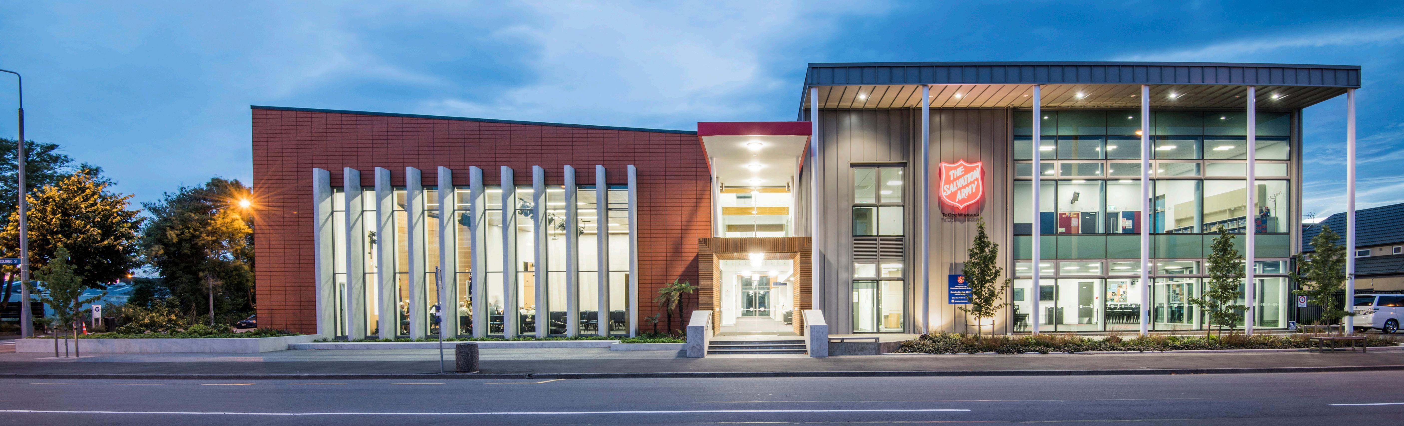
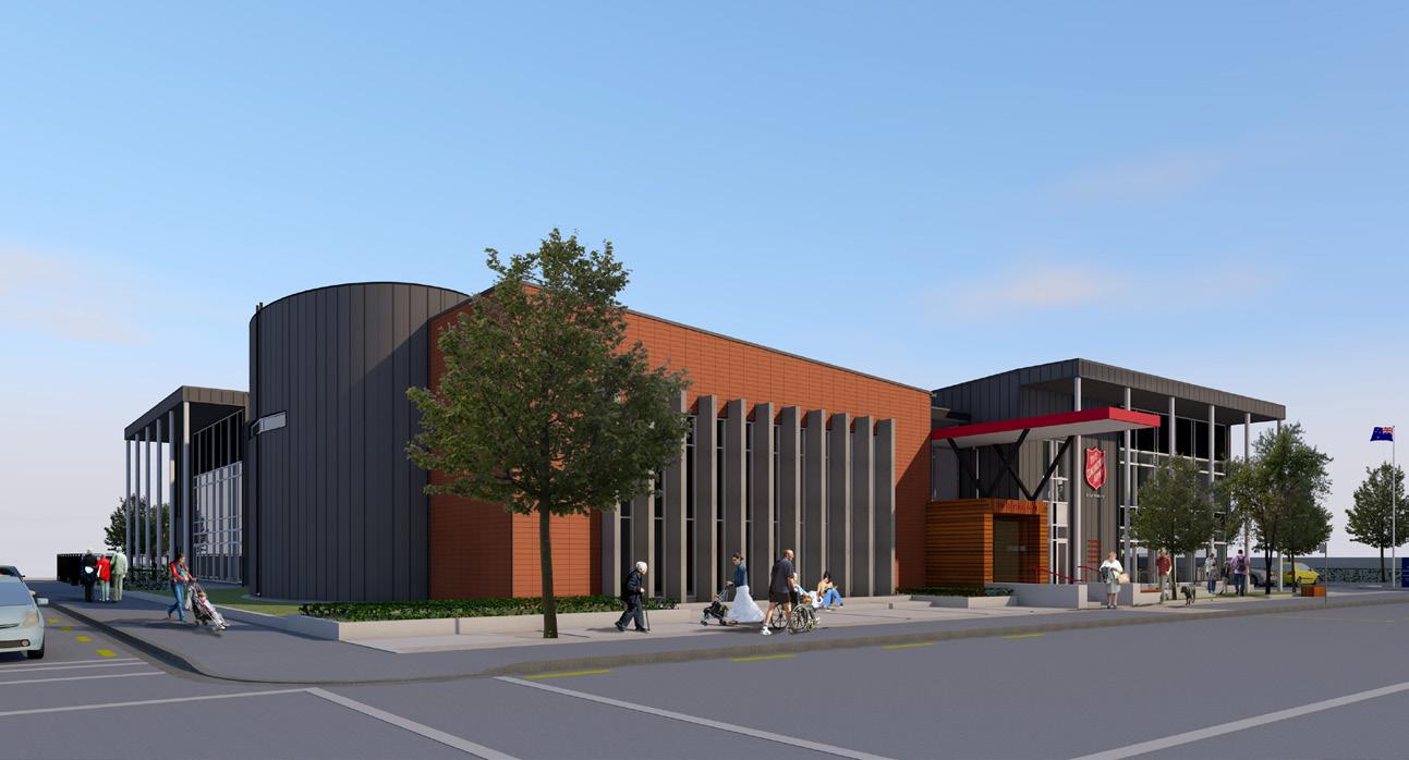
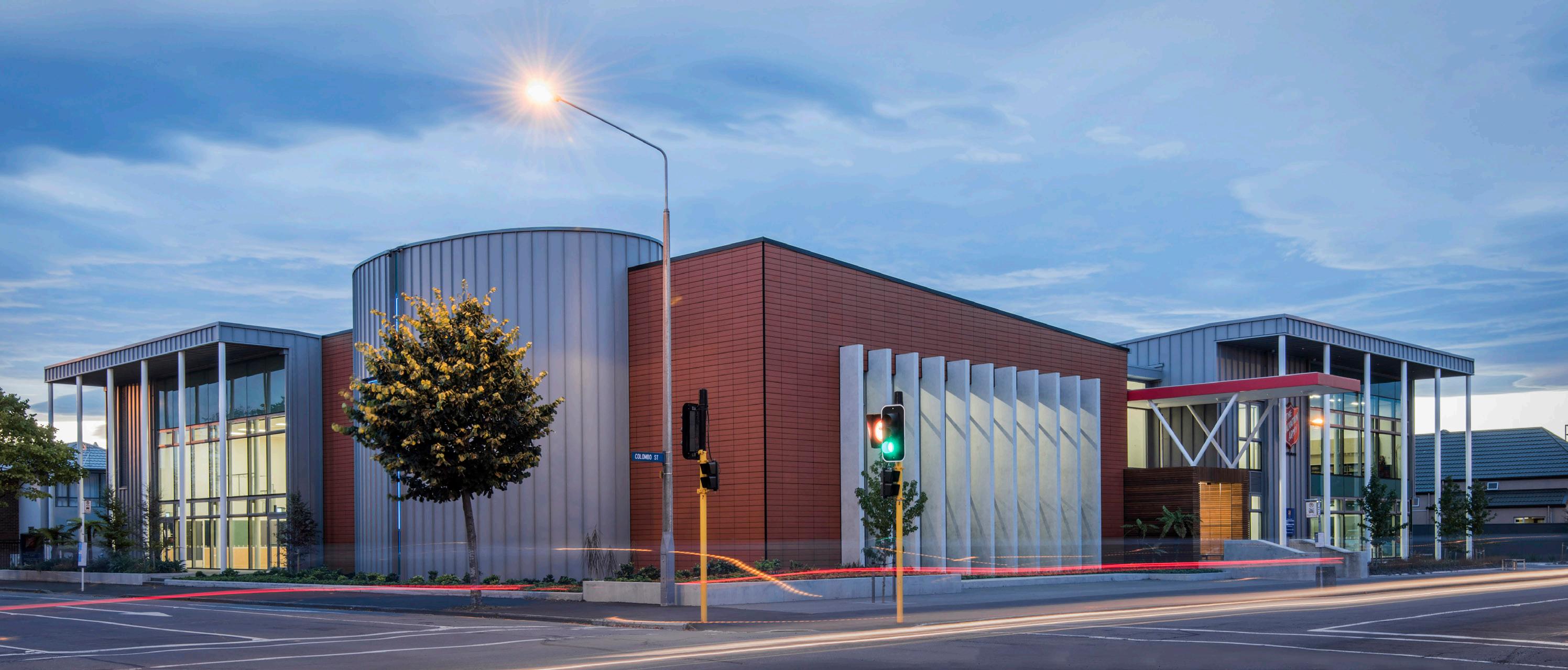
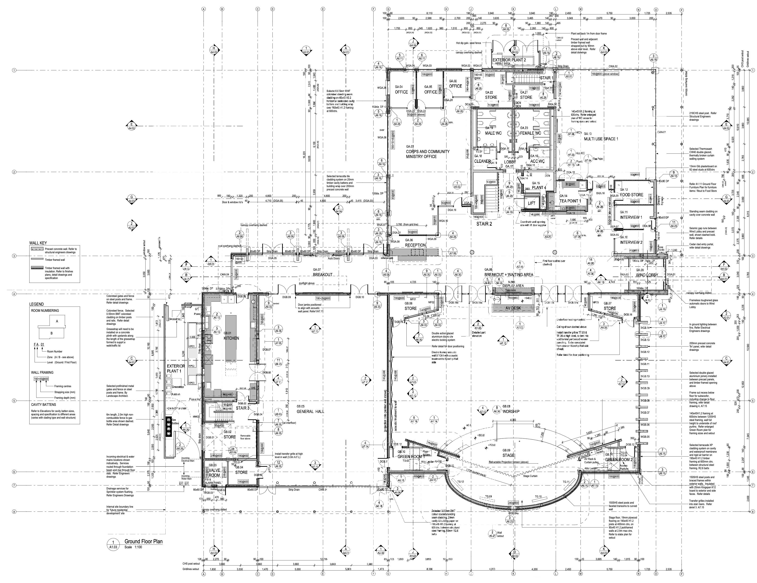
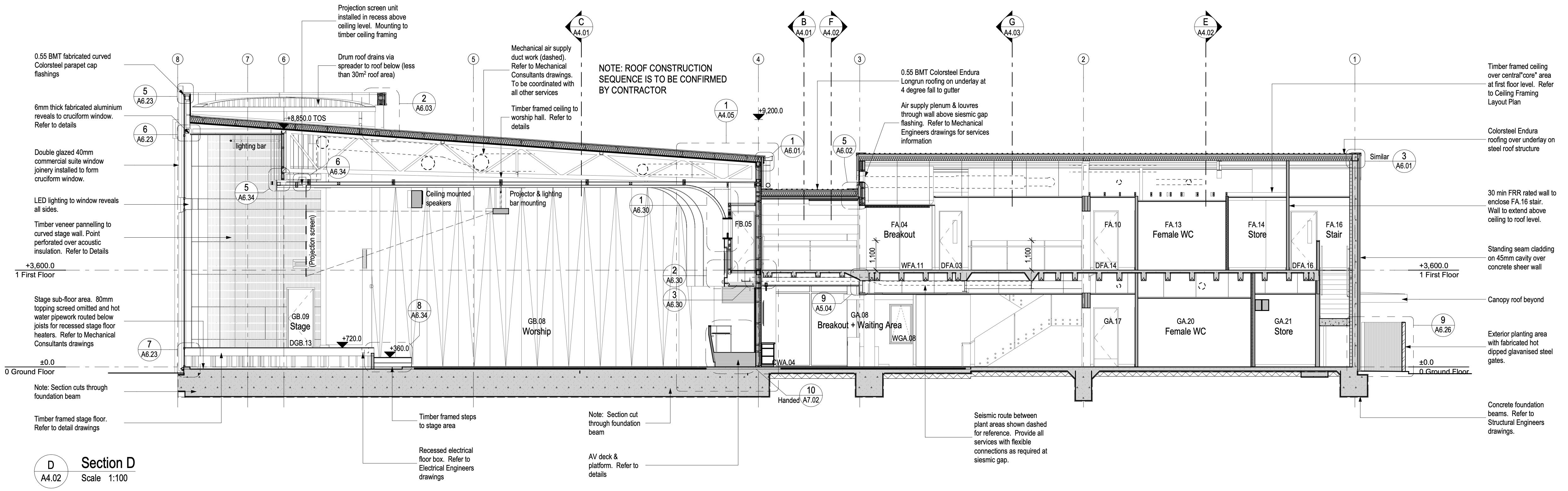
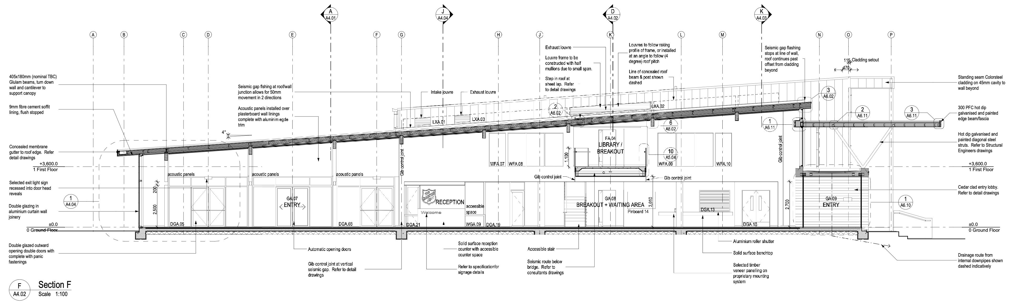
The Gracefield Development on Colombo Street centralises various Salvation Army functions throughout Christchurch and the South Island region. The design is a single purpose-built complex. It consists of a worship hall, sports hall, offices, meeting rooms and commercial kitchen.
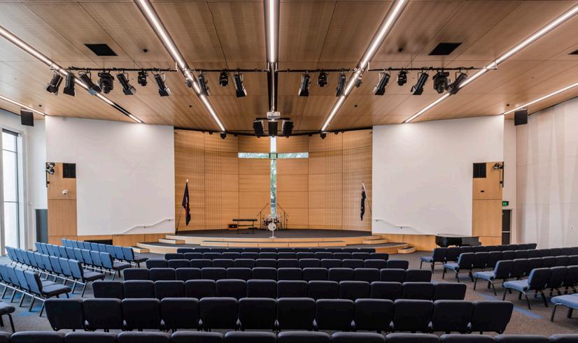
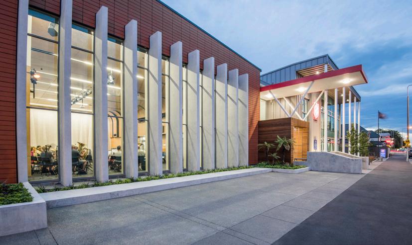
The various spaces have been positioned around a cross that was ‘laid out’ on the site, and forms the major circulation through the development. The development is strong on other symbolism as well, including the ‘11 Articles of Faith’ concrete fins to the front of the building through which the outside and inside worlds are engaged, the ‘12 Disciples’ pilotis that address the streets, and the worship hall stage ‘drum’.
The acoustic design has been a notable success for the Salvation Army band and choir, with the New Zealand Army Band also utilising the space to record their music within the worship hall.
The practical detailing and simple massing of forms sits well with the heritage and mission of The Salvation Army.
RESPONSIBILITIES
• Collaborating in-house with the project lead, an interior designer and several architectural technicians.
• Concept drawings during the initial phases of the project in 2008-2009.
• Concept and developed design visualisations for client sign off and in-house design reviews throughout the life of the project.
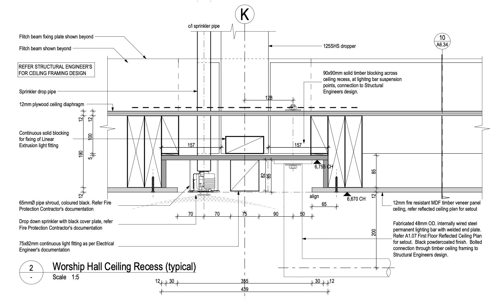
• Coordinating suspended ceiling layouts between the architectural and services engineers to provide well though out, logical layouts, particularly within the main worship hall space.
• Coordination with the structural engineer through the use of OpenBIM geometry.
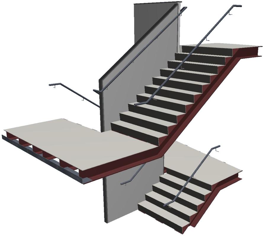
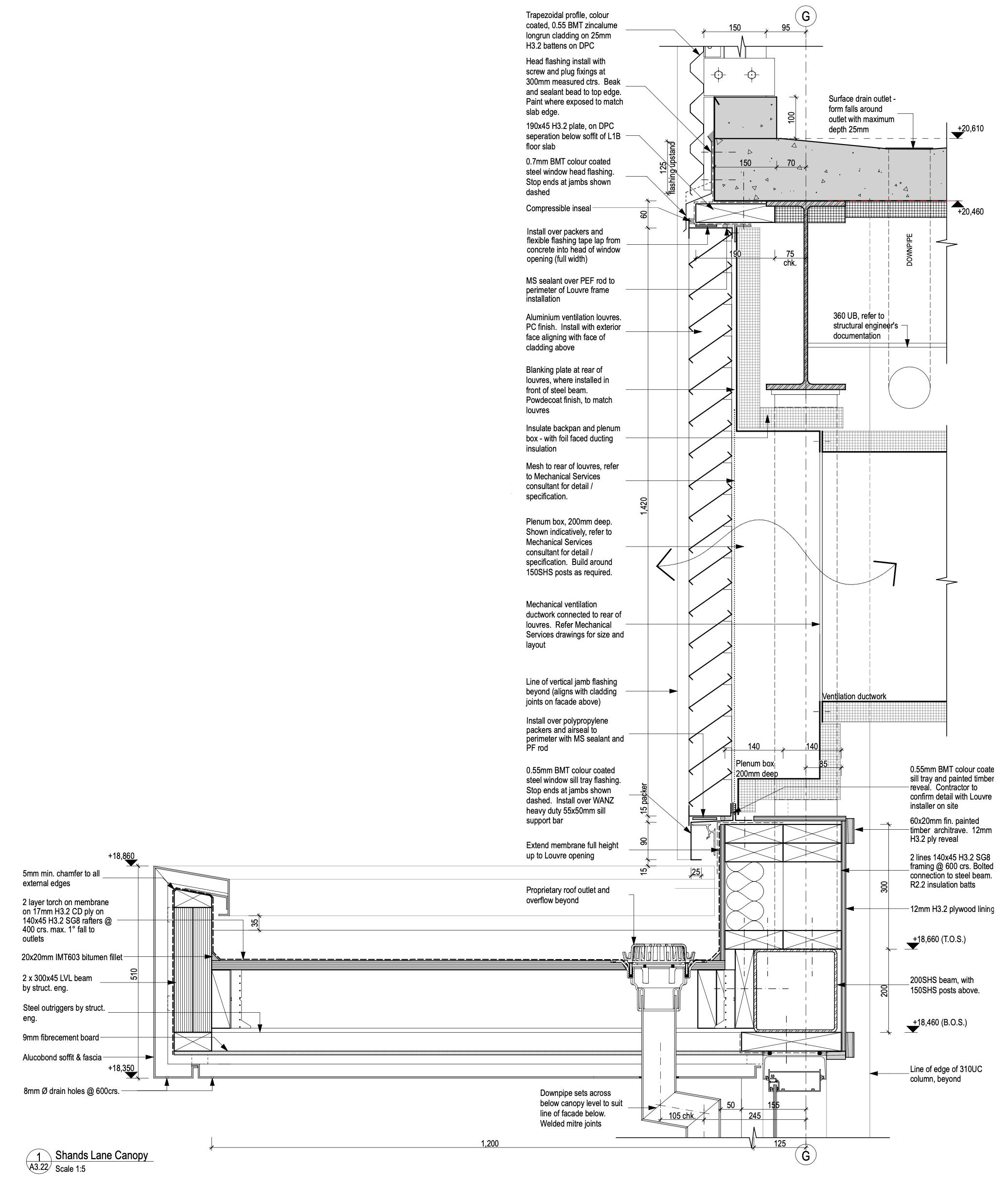
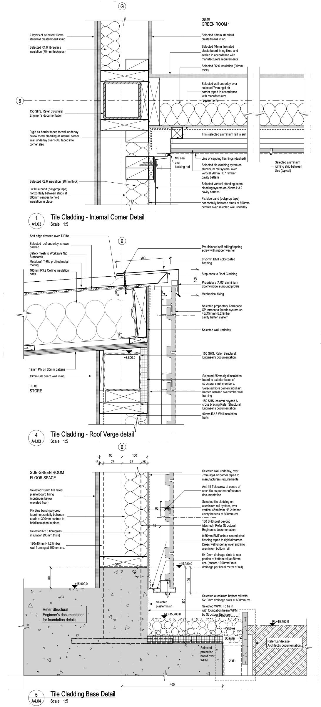
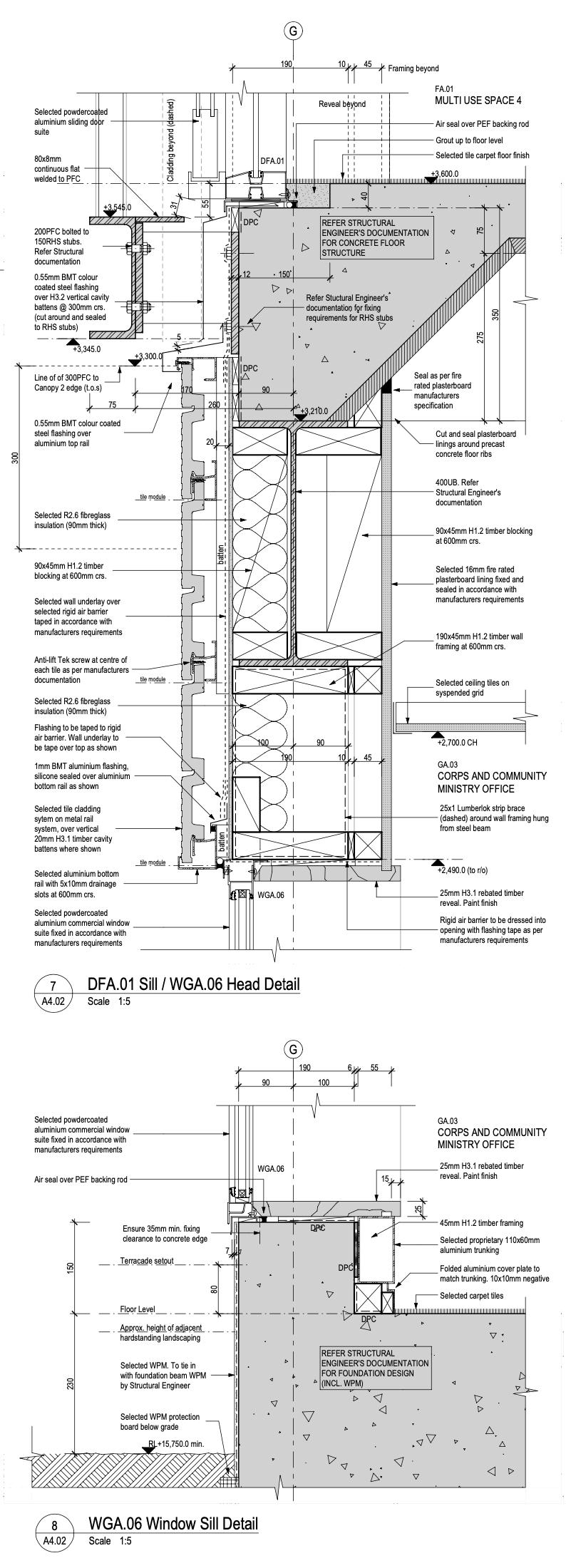
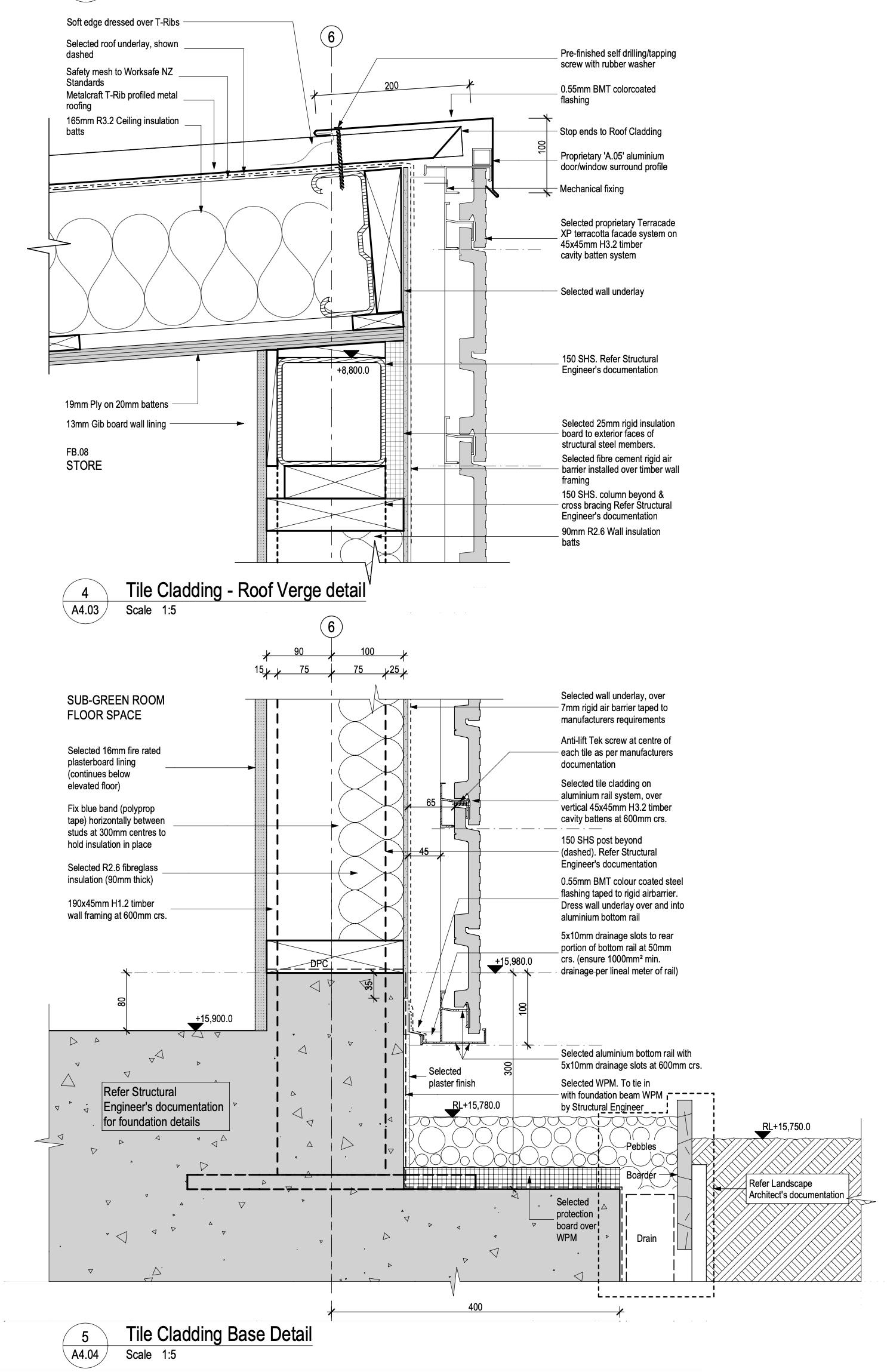
• 2D construction documentation across the project including general assembly drawings, floor slab and services penetration setout, terracotta facade detailing, metal tray cladding, main entry canopies, internal stair detailing, worship hall feature ceiling, coordinated reflected ceiling plans, and door and window schedules.
• Revision management and document control to ensure accurate communication with all stakeholders.
• Supporting the various project leads during several phases of value engineering and structural redesign following the Canterbury earthquakes.
• Detailed evaluation of the revised structural design following the 2011 February earthquake, and the implications on the architectural detailed documentation.
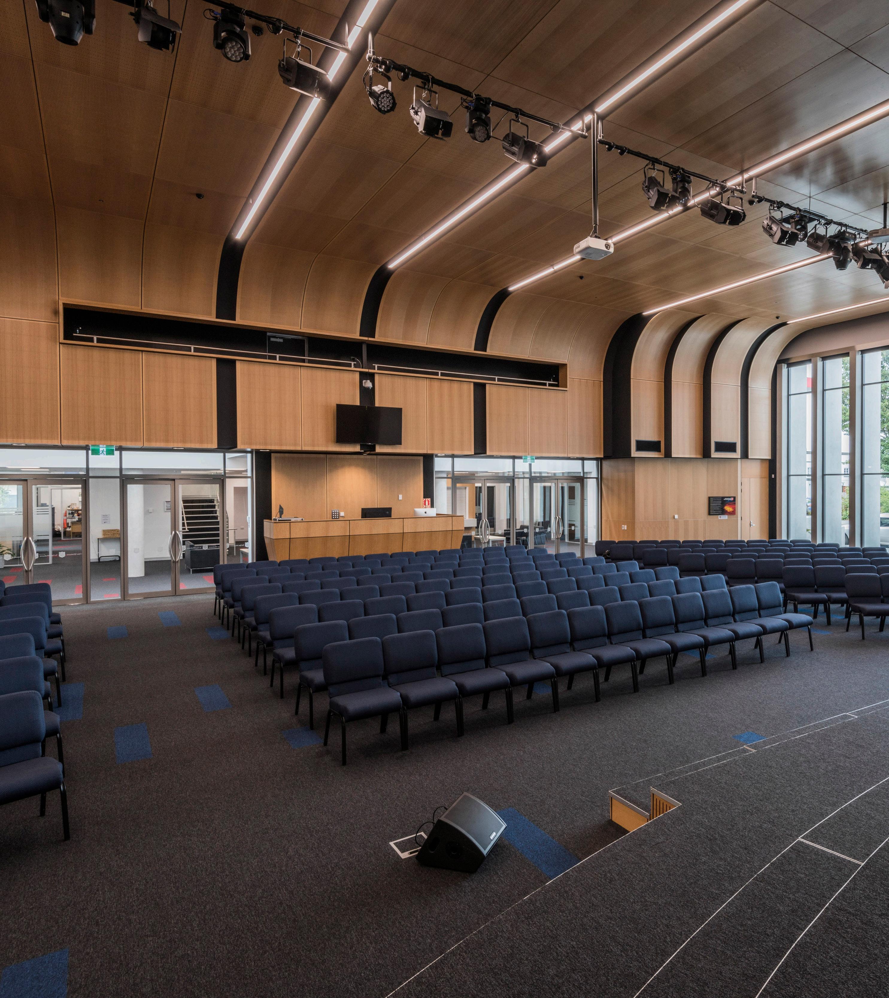
Opposite page: Worship Hall This space includes several acoustic features to both absorb and deflect sound. The black linear rebates along the ceiling and down the rear wall contain many of the small ceiling mounted fixtures (lights, sprinklers etc) which provide a clean ceiling surface,
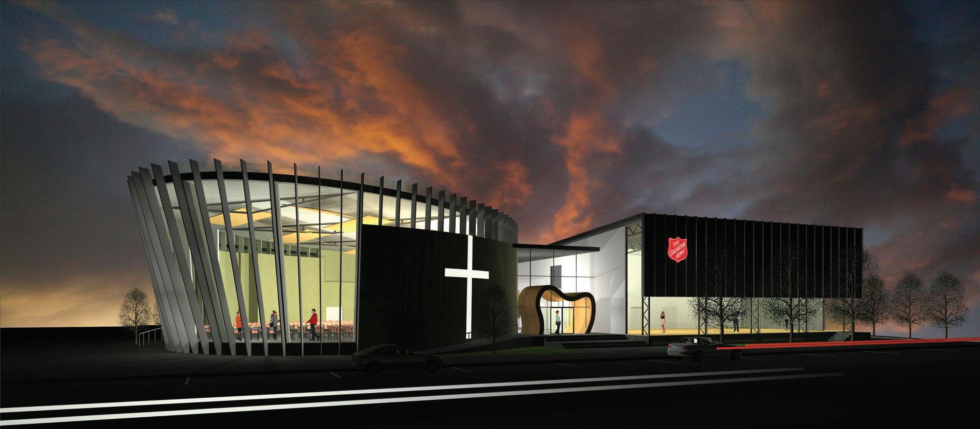
Concept Design 2008
As a part of the team during the initial concept design, it was a privilege to continue a pre-existing relationship with The Salvation Army, having grown up in ‘The Sallies’.
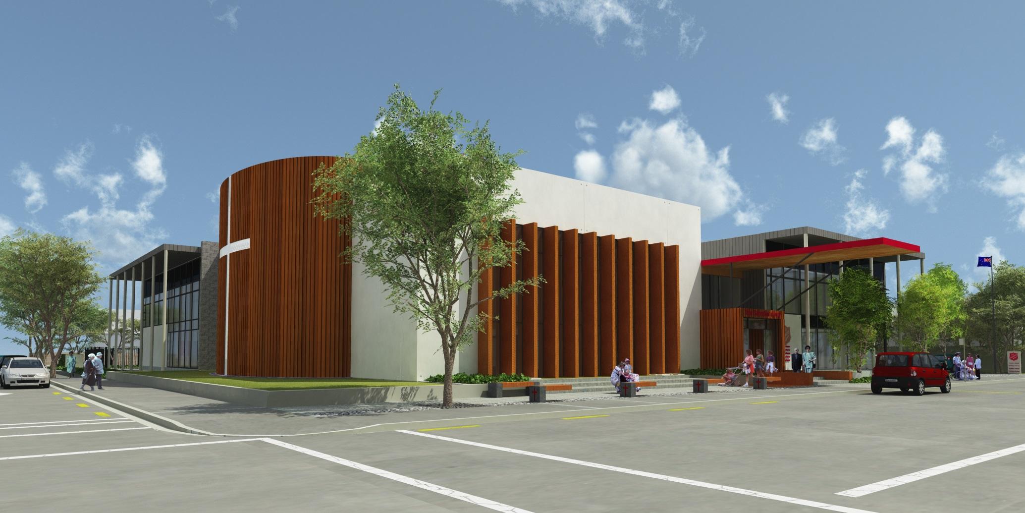
Revised Developed Design 2010
Prior to the Canterbury earthquakes, a complete set of building consent documentation had been finalised, and was due to be lodged with Christchurch City Council.
Final Design 2015
Following the Canterbury Earthquakes, a revised design was produced to accommodate revised seismic design requirements, revised Building Code clauses and an increase in overall constructions costs.
A cast of many
During the almost 10 year process, many members of the team came and went for a variety of reasons, but ourselves as the Architects were privilaged to be involved from start to finish. During the project we had:
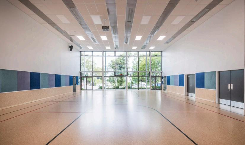
Worship Hall
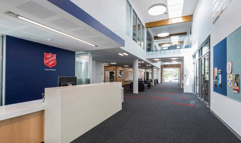
Reception
General Hall
Colombo Street Entrance
First Floor Bridge
Multi use Space 4
Worship Hall Ceiling
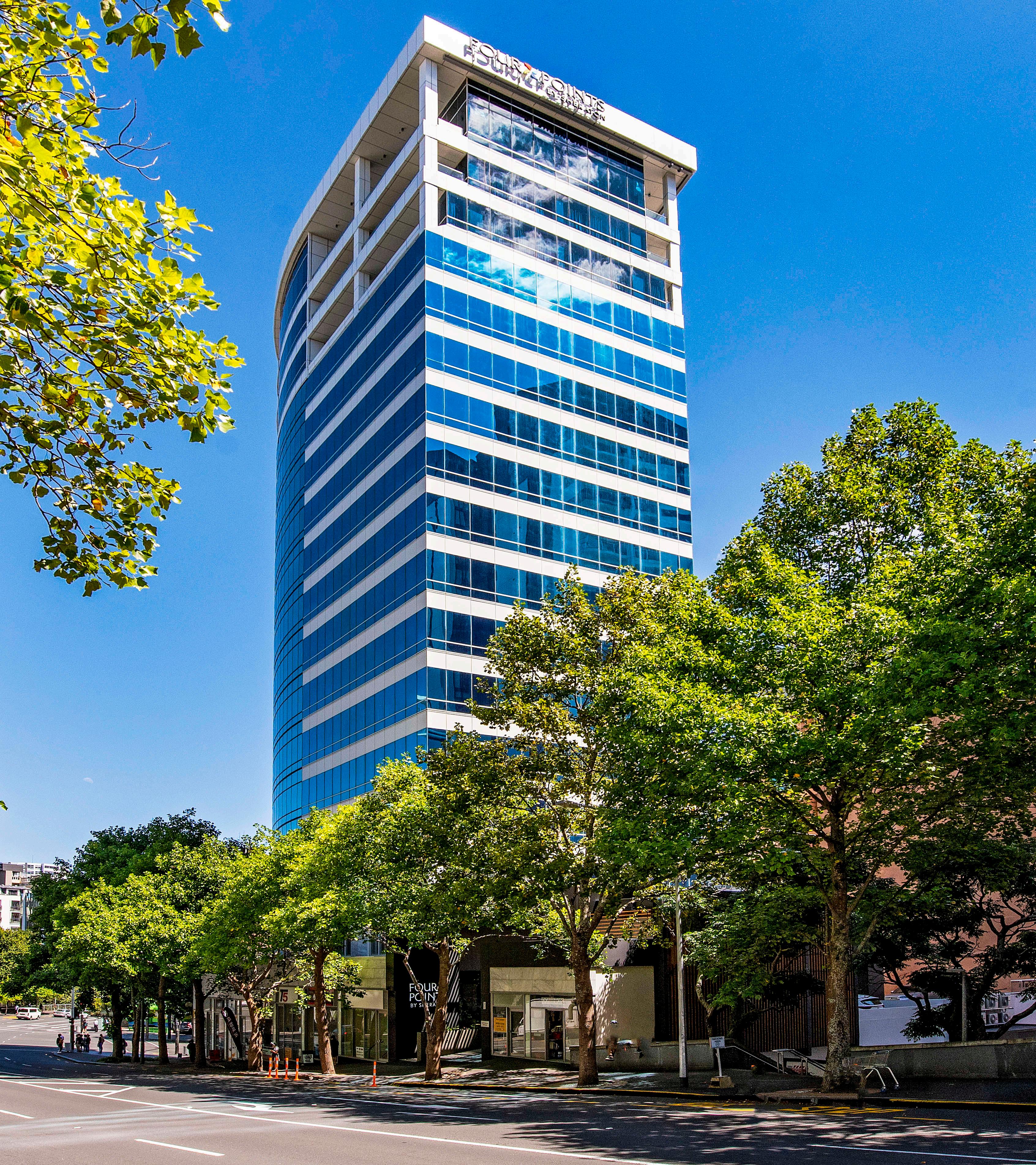
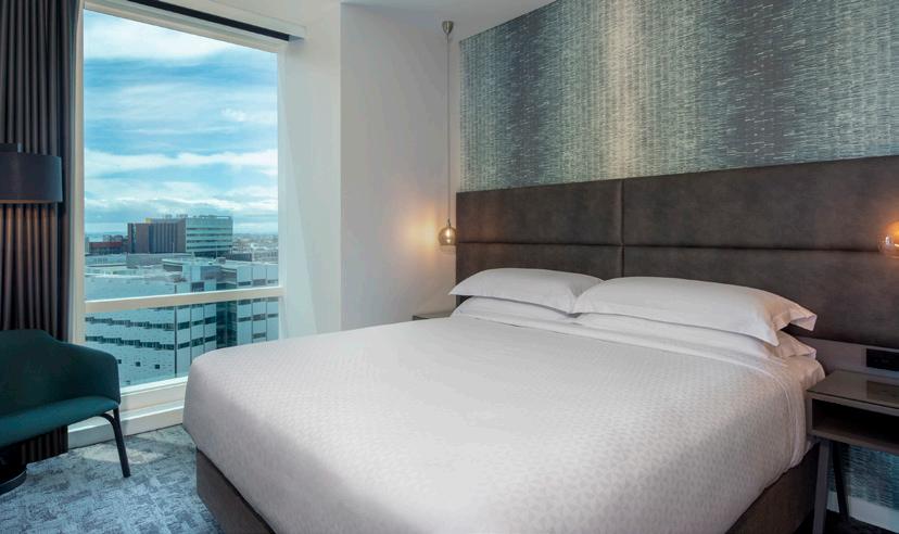
Four Points by Sheraton
INFO Type: Hotel
Place: Central Auckland
Year: 2020 - 2021
Client: Russell Property Group
Roles: Architectural Technician
Architectural BIM Manager
Document Controller
Phase: Developed Design
Working Drawings
Building Consent
Observation
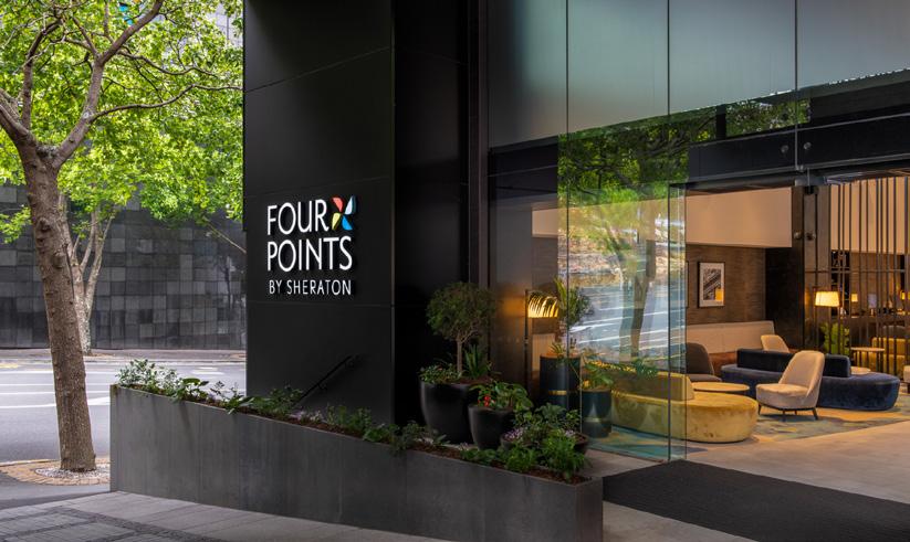
DESCRIPTION
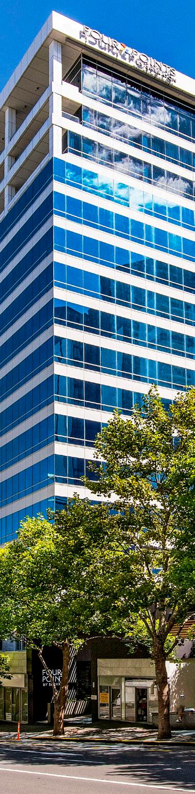
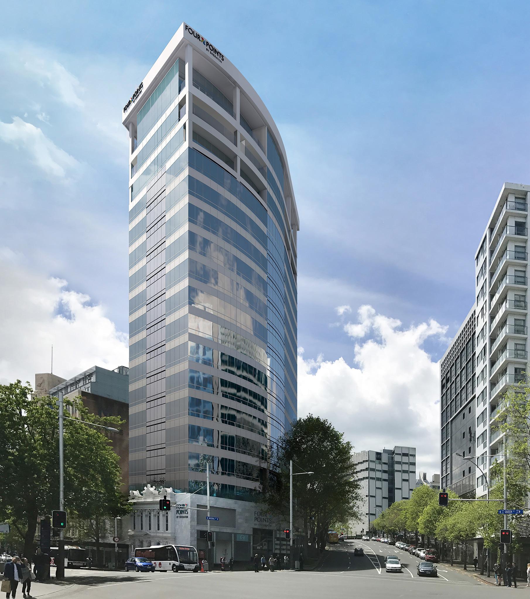
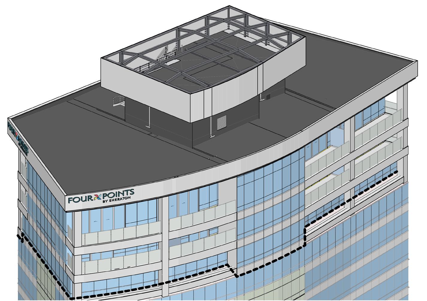
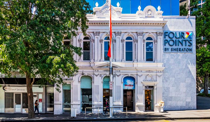
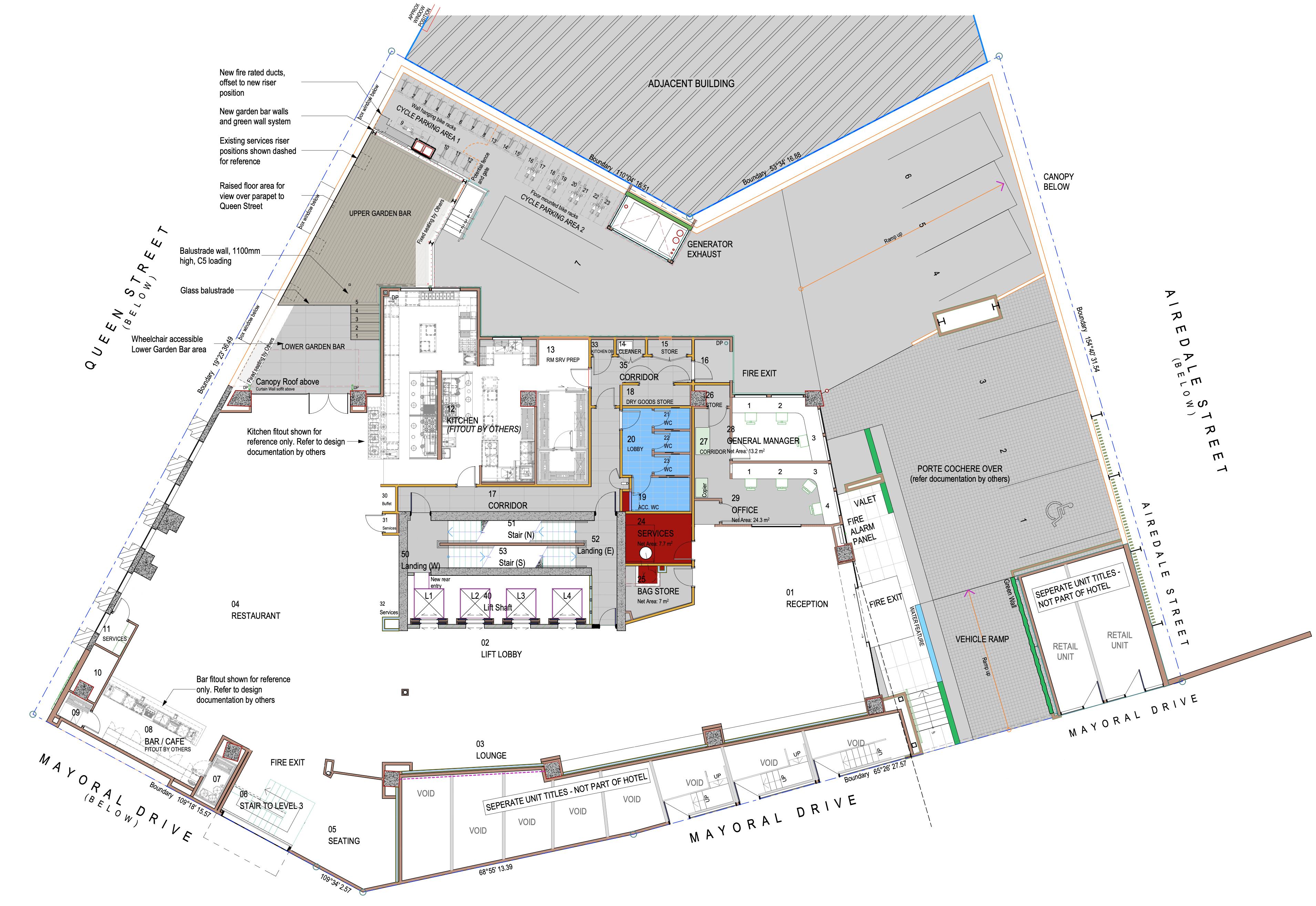
This new 255 room 4 1/2-star hotel on Queen Street was the conversion of an existing office building which had been stripped out in preparation for the design phase. The existing office building created significant challenges for the design, not the least being that no exterior walls were parallel and one curved. That meant that the layout of the guest rooms was a challenge, but also allowed for some creative solutions.
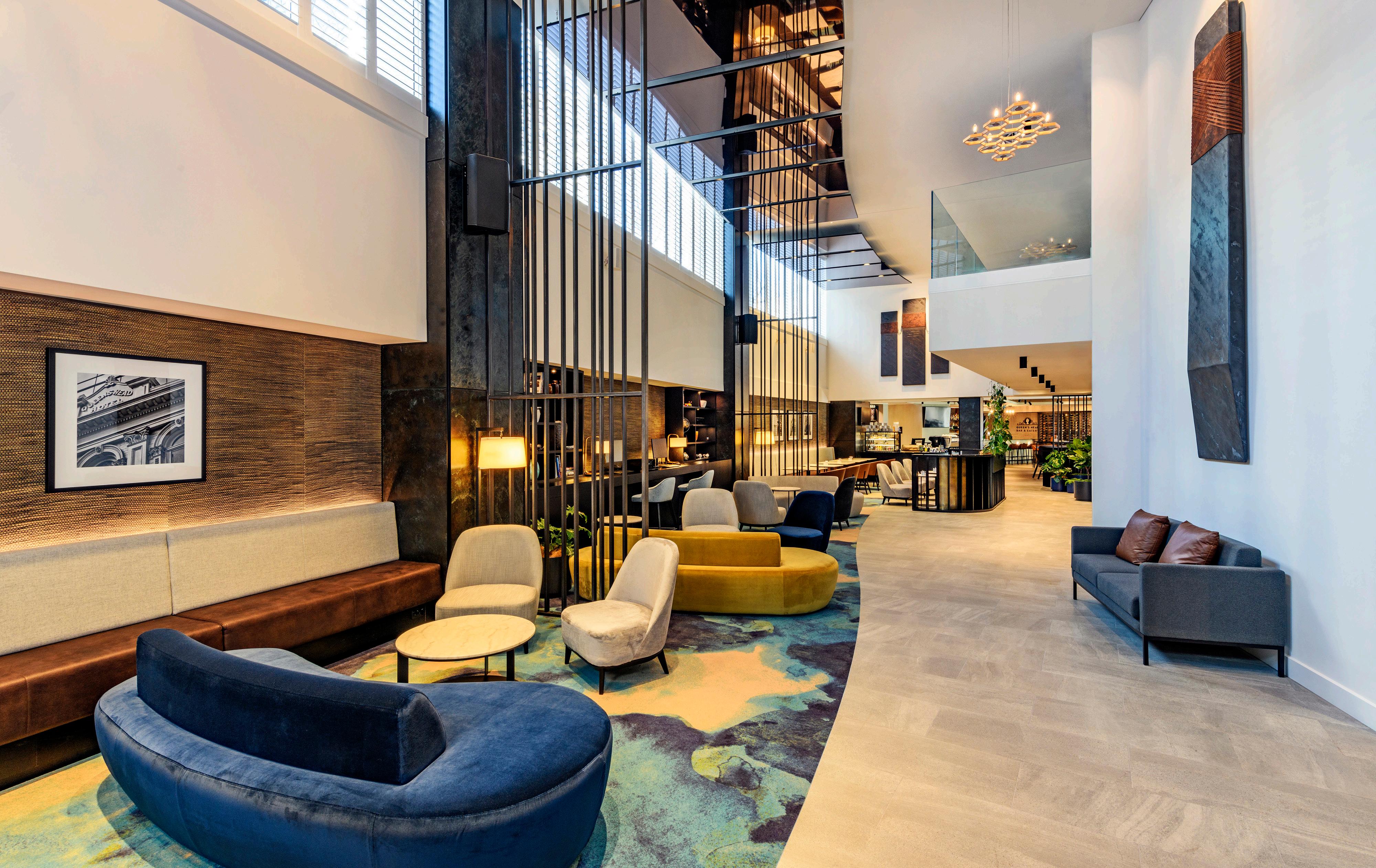
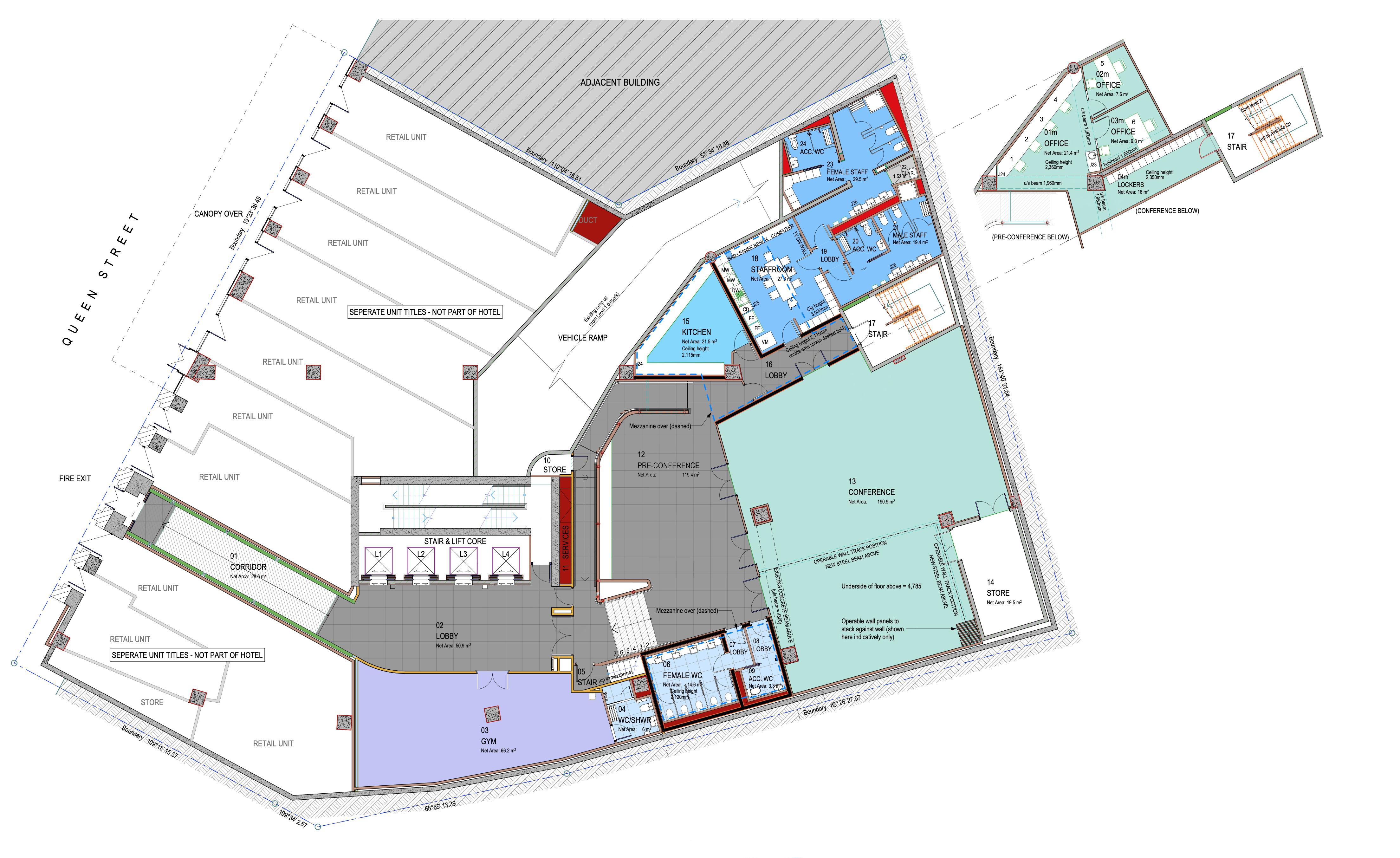
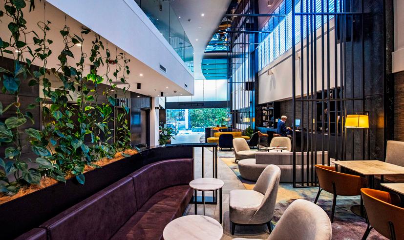
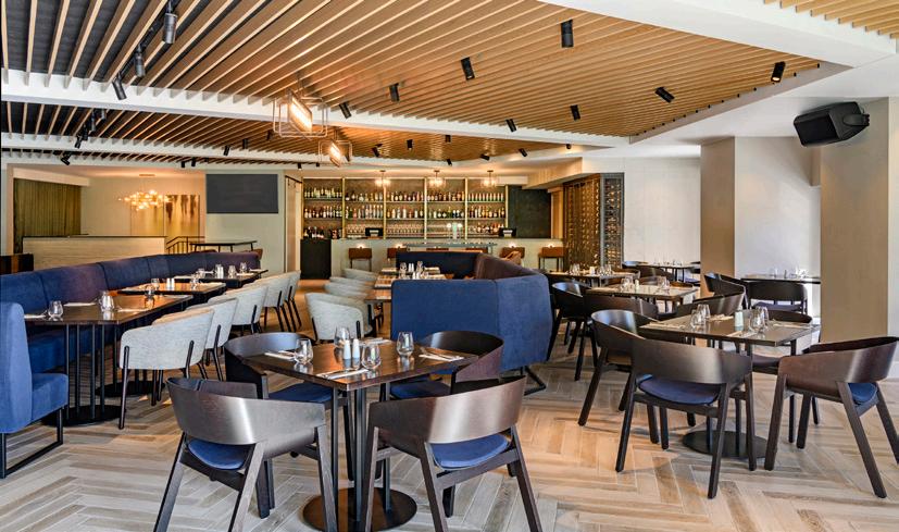
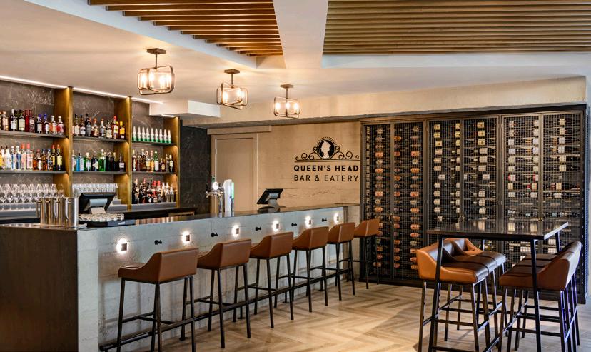
The new hotel features full conference facilities, double height entrance foyer, restaurant and bar with full commercial kitchen, as well as a roof top bar
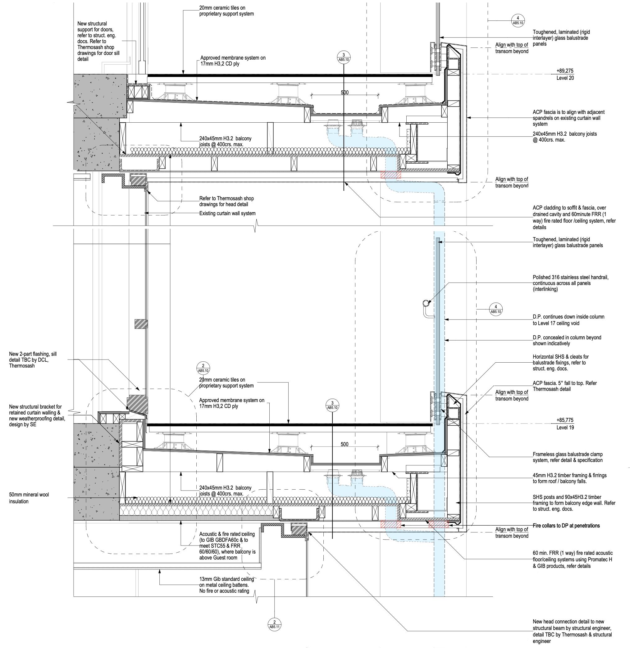
New floors and plant decks were added to the top of the building to accommodate the hotel’s requirements. These new upper levels were clad and glazed to create a unified façade treatment with the retained blue glass facade below
Considerable consideration was given to where the main entrance to the hotel would be, as well as back of house and deliveries, due to operational requirements and weather considerations. As part of this, a new porte cochere was also added at the main entrance.
RESPONSIBILITIES
• Collaborating in-house with the project lead, a supporting senior architect, and several architectural technicians.
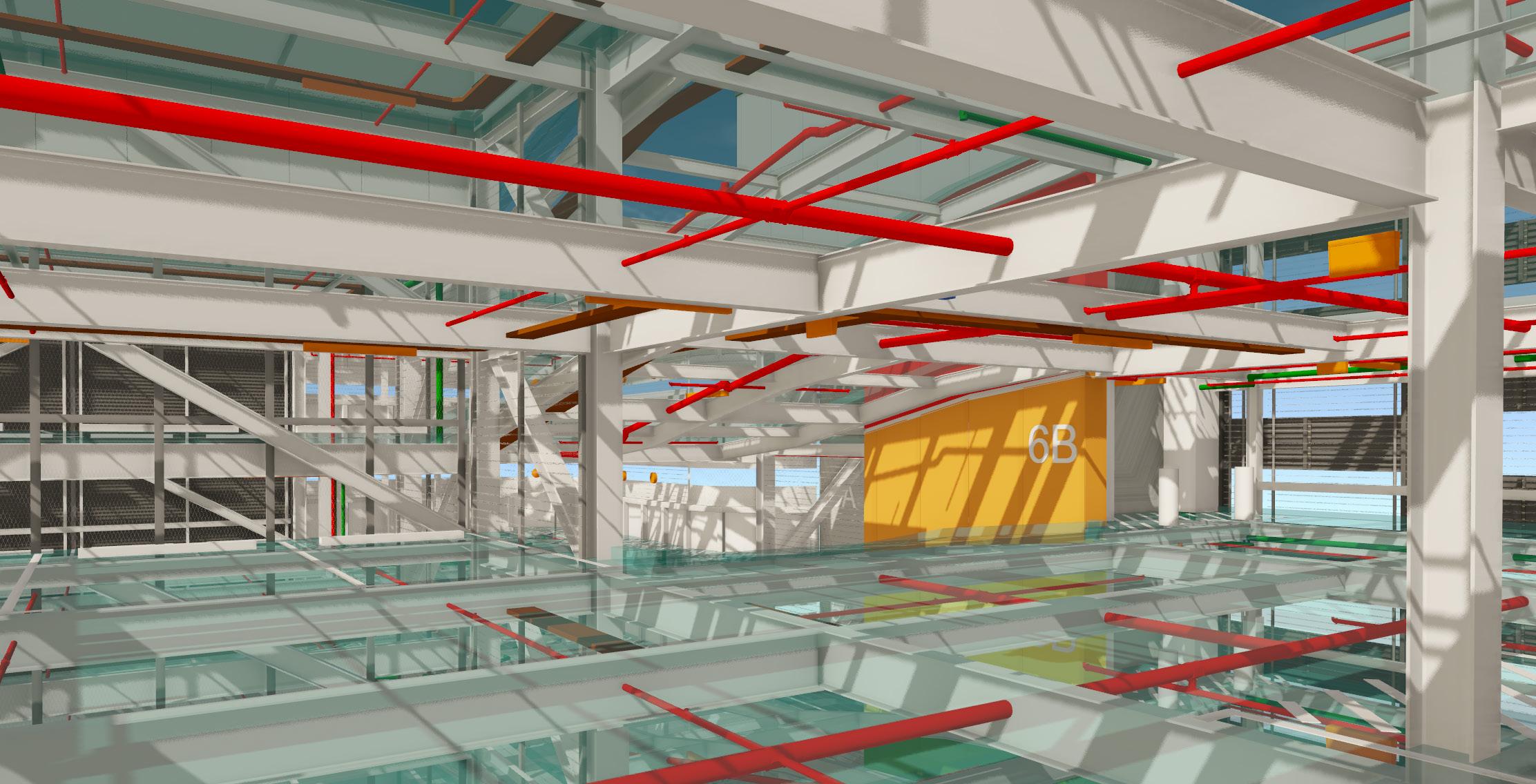
• Working with the project lead during the developed design phase to provide room layouts for all hotel room floors, as well as the conference spaces and other supporting facilities.
• Existing, demolition and new floor plans.
• Revision management and document control to ensure accurate communication with all stakeholders.
• Archicad file management, including the management of the staging within our documentation.
• Extensive BIM modeling for visualisation and architectural documentation production.
• Coordinating suspended ceiling layouts between the architectural and services engineers to provide logical layouts within the hotel rooms and shared spaces.
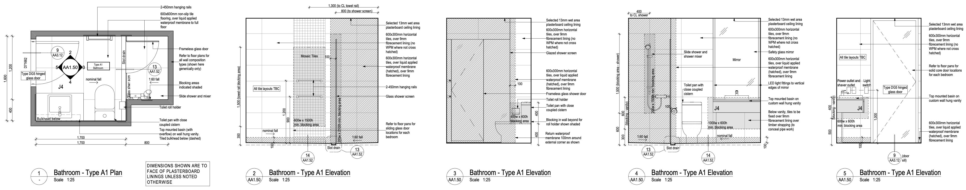
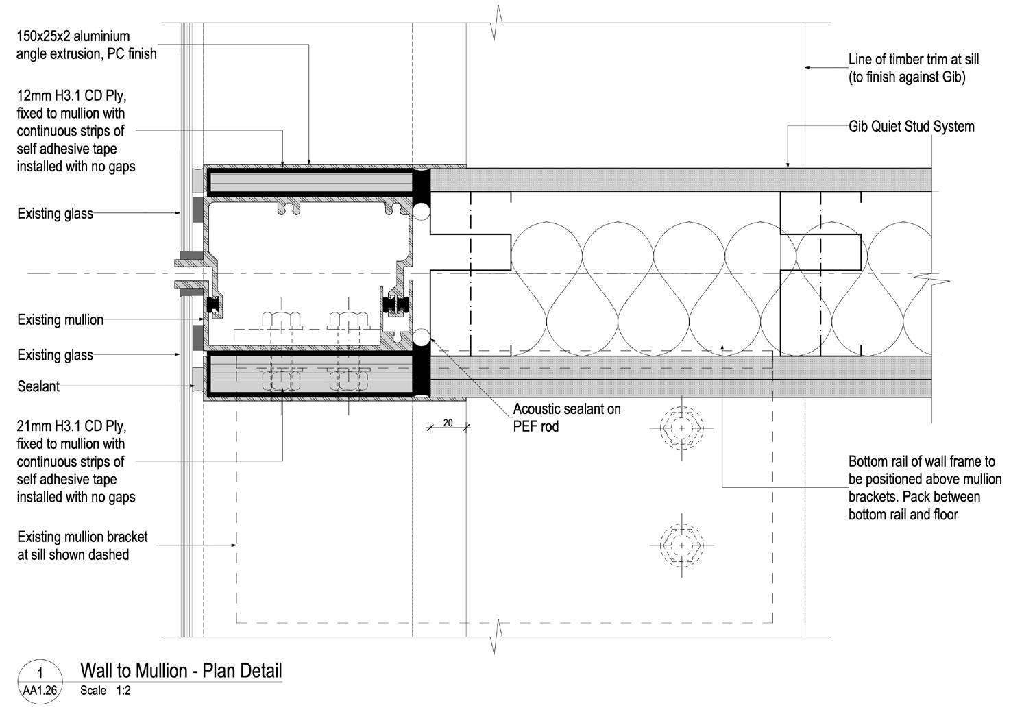
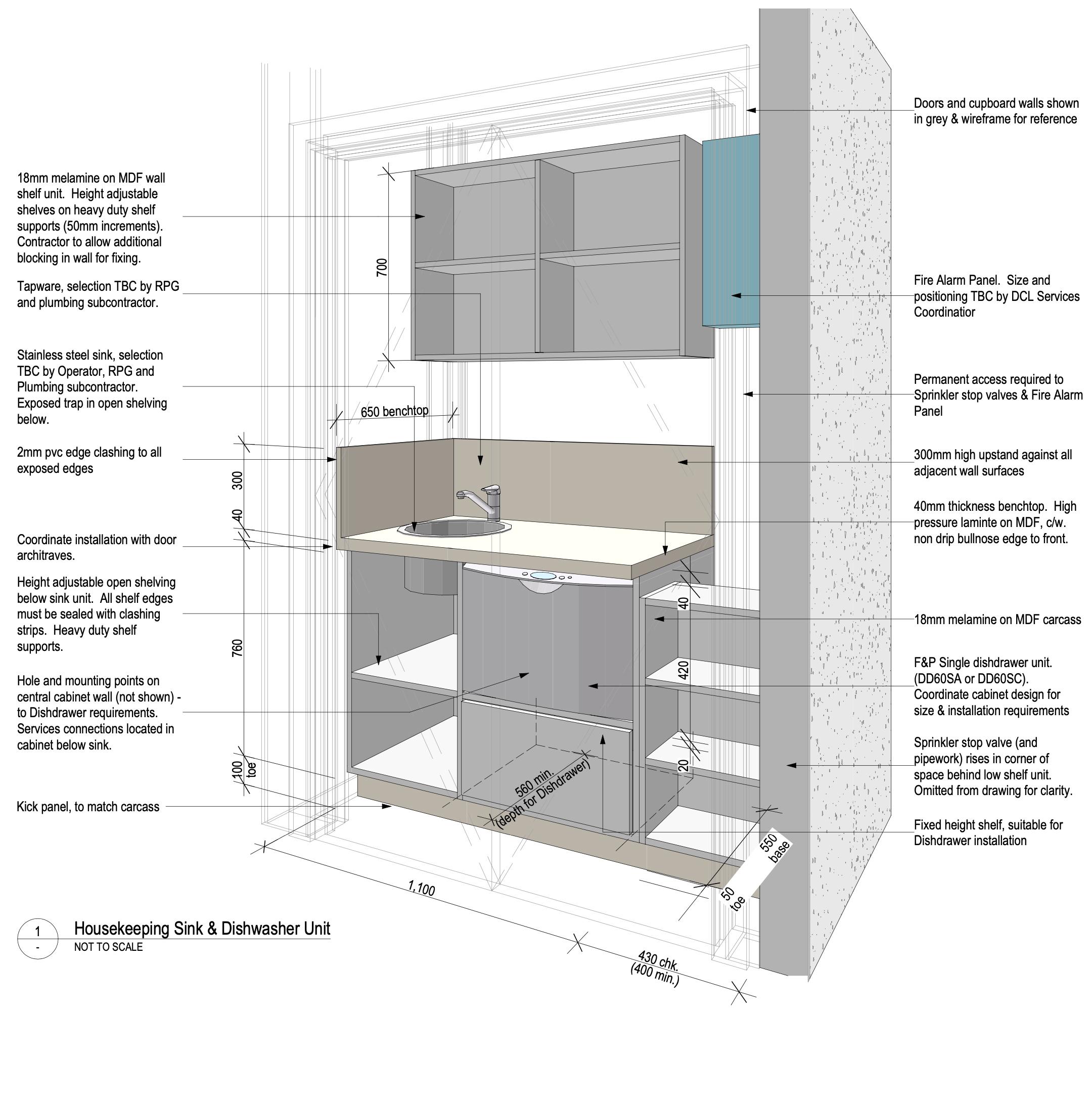
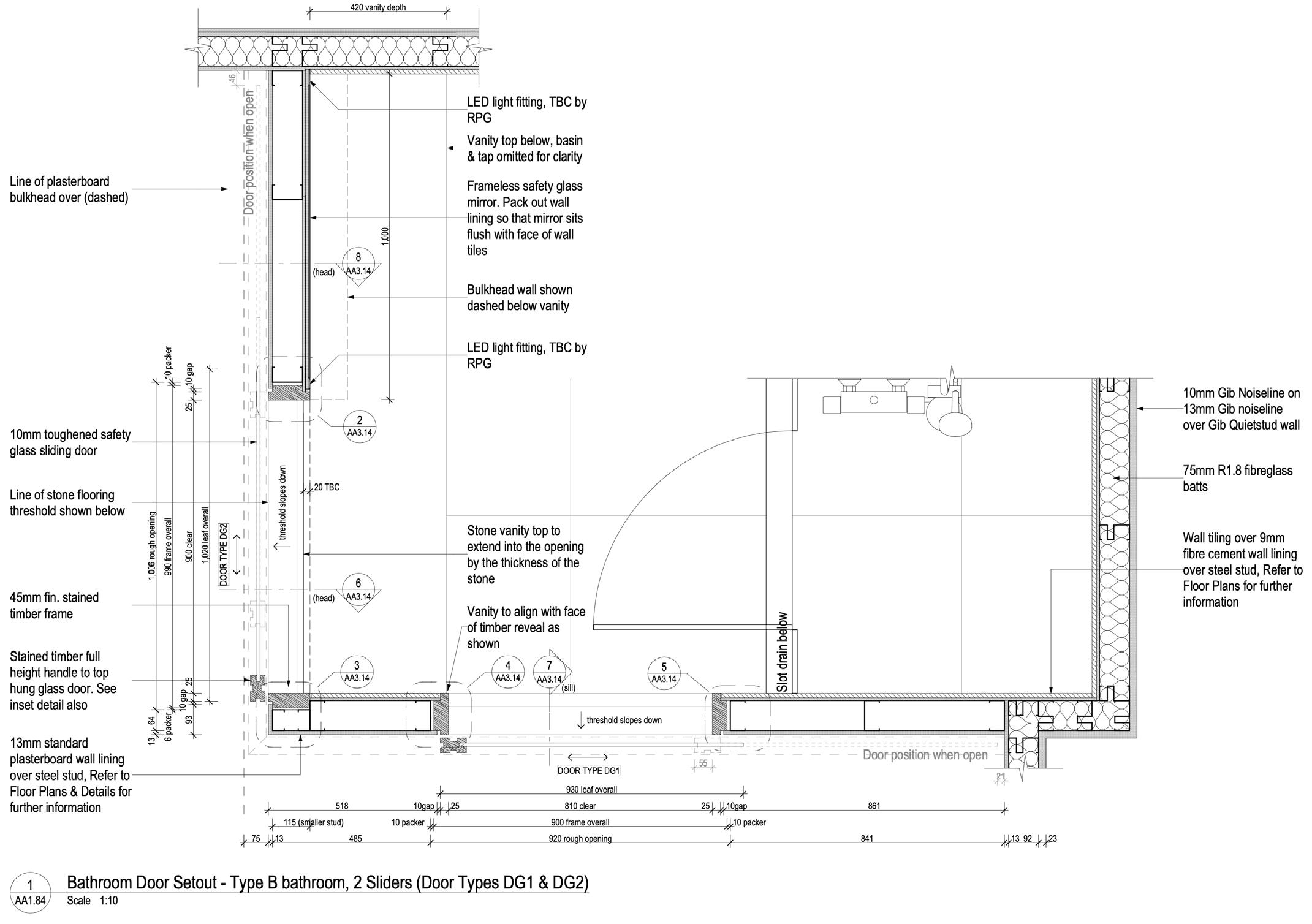
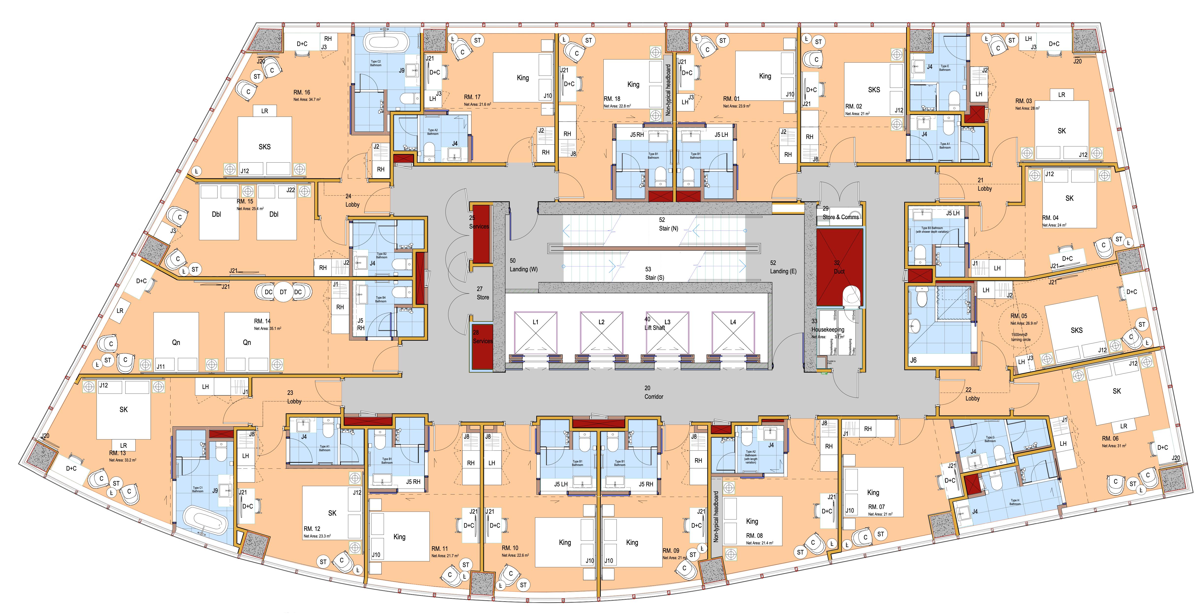
• 2D construction documentation across the project, including general assembly drawings, the commercial kitchen extension on level 4, documenting all interior wall types, interior plans and elevations of all hotel bathroom types, door and window schedules, bathroom joinery drawings, fire and acoustic rated door details.
• Extensive coordination with the curtain wall supplier.
• Detailed hotel room setout which was critical given the unique shape of the existing building and therefore the rooms and doors.
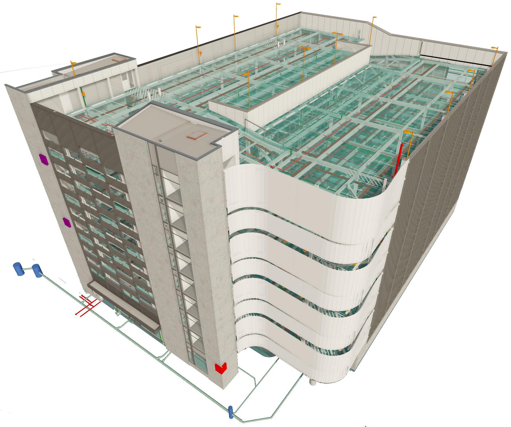
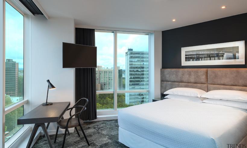
Opposite page: Completed exterior South and west facades viewed from Mayoral Drive. New floor levels 18, 19 and 20 include balconies overlooking central Auckland.
• Supporting the project lead in his full observation role, which was an intense process given the nature of the project.
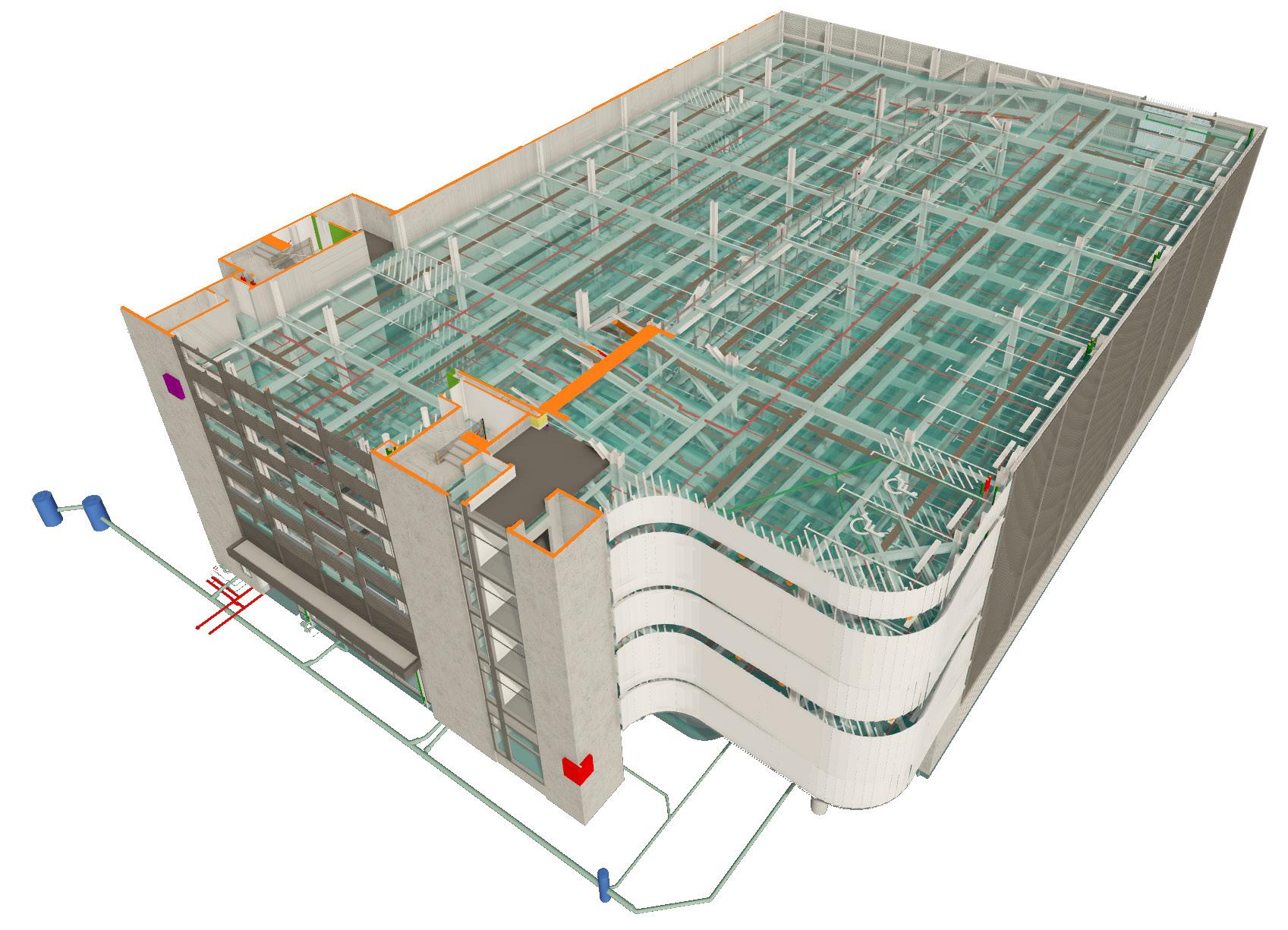
Architectural model
Due to the scale of the project and the complexities of the MEP services inputs, a balance between detail and file speed was necessary to maintain a usable architectural model. Repetitive items were modeled once and linked to each instance within the model, which allowed us to amend the model relatively quickly when required.
Opposite page: Final render This final image was produced using a mixture of Archicad and Photoshop, in order to sell the development to potential operators.
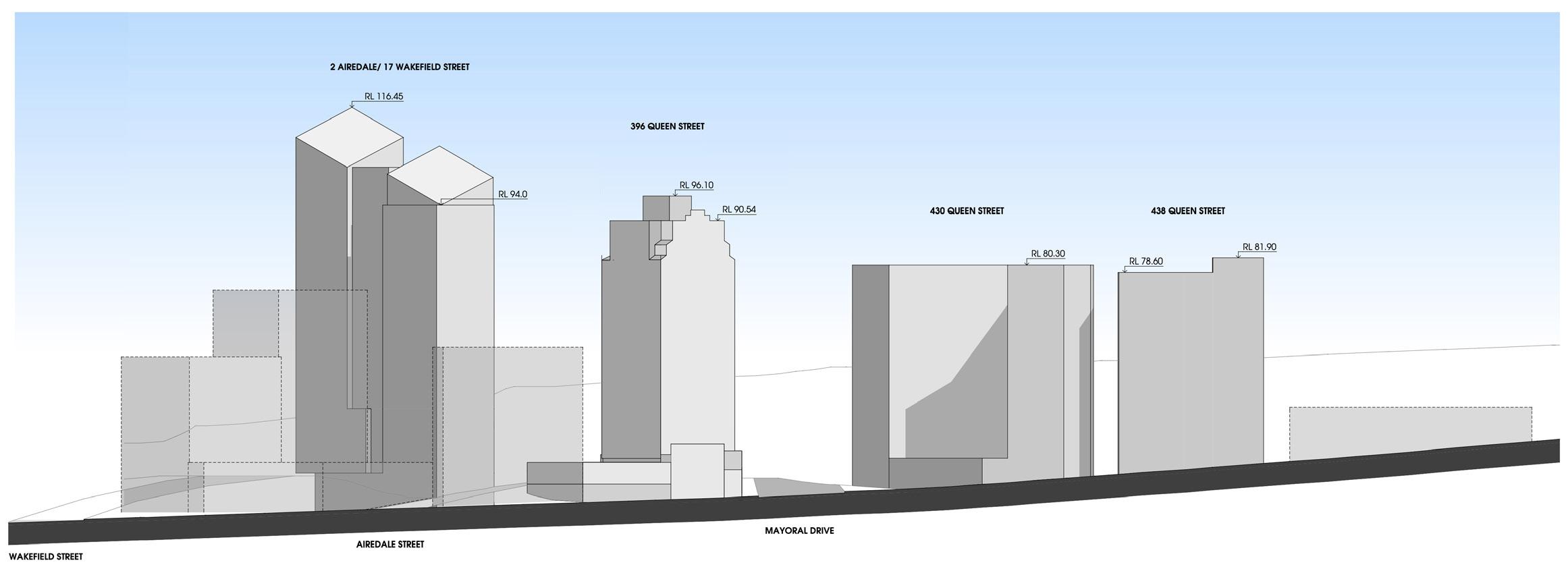
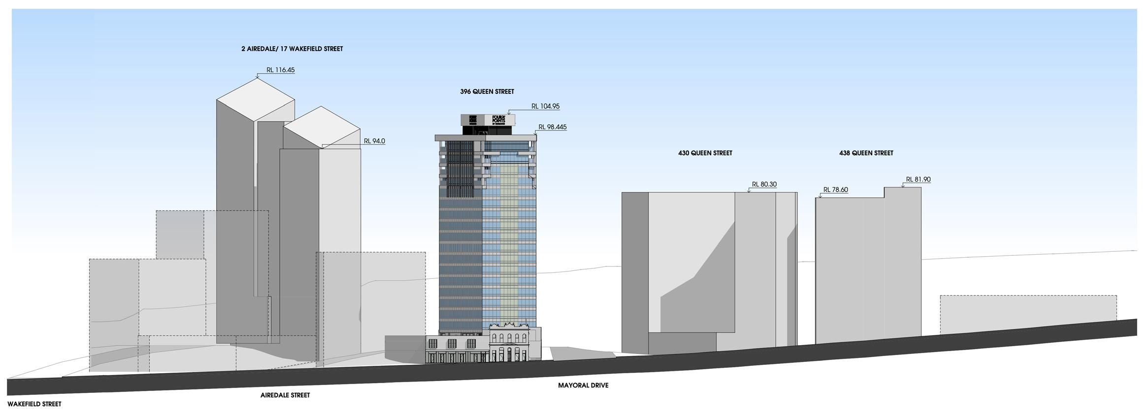
Existing site elevation
New site elevation

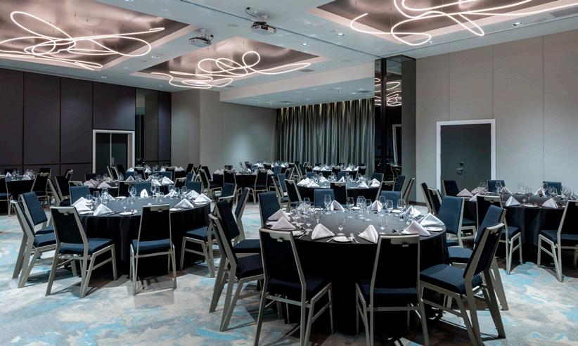
Conference Room
Private Dining
Entry from Porte Cochere
Lounge
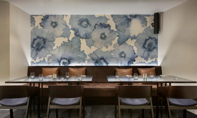
Restaurant
Bar and Eatery
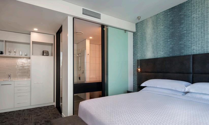
Kitchenette and Bathroom Entry
Bar
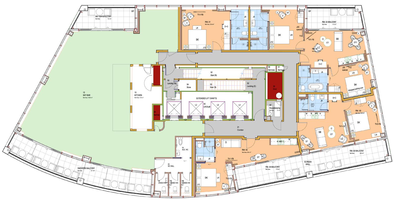
New Fitout Plan - Typical Levels 6-17
New Fitout Plan - Level 20
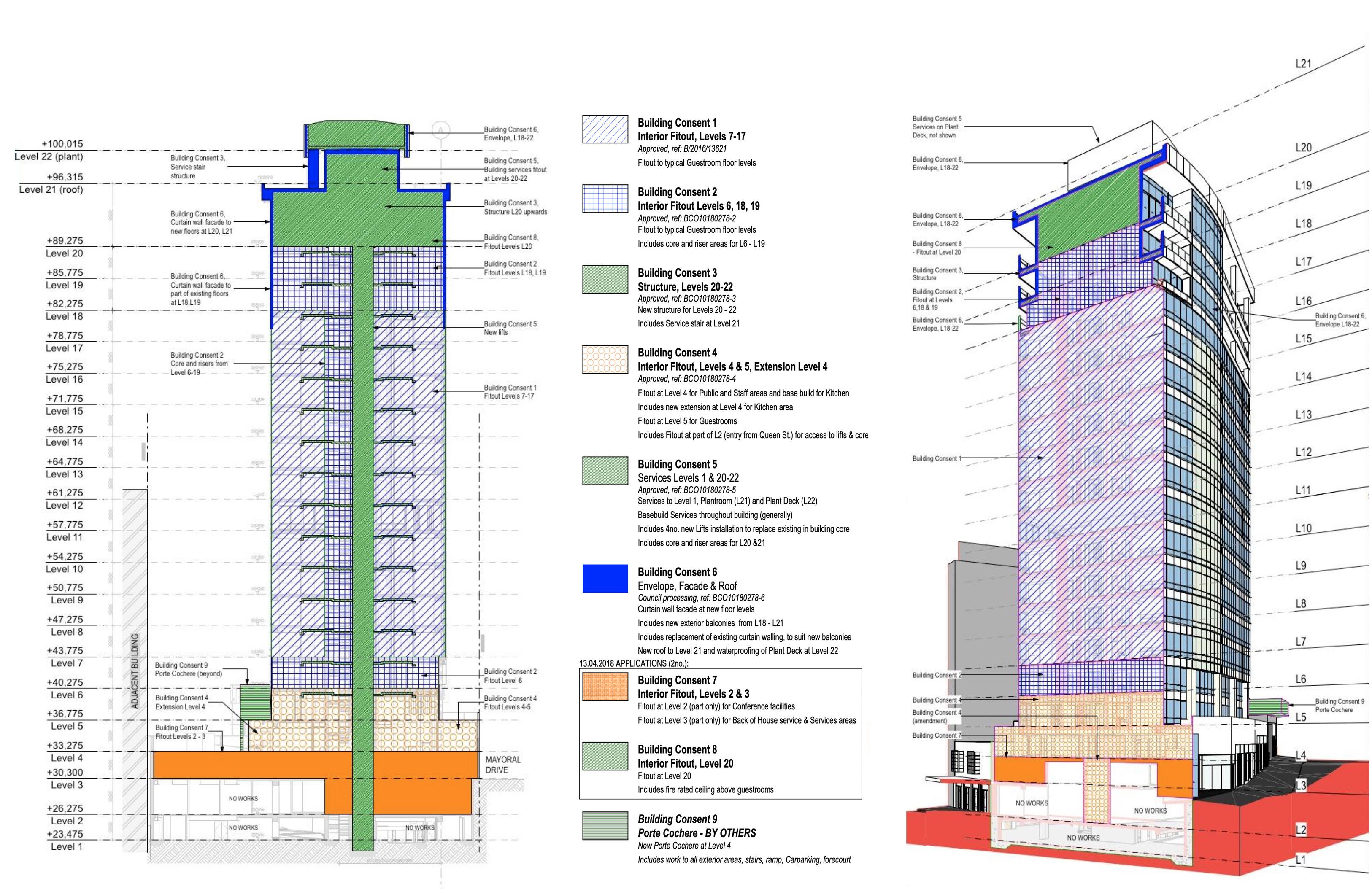
Building Consent staging diagrams (above)
The construction works and building consenting were largely developing concurrently which created significant challenges when it came to the scheduling of the various package of architectural documentation. The above diagrams were kept current and provided clarity around this.