Computational Design Portfolio | 2024 Chin Kee Ting

I believe that good design stems from an understanding of the human condition, and should be a smart response to its context. Combined with my passion in digital computation, I actively pursue designs that are cost-effective, efficient and elegant.
Mar 2022 - Present
Assistant Architect
ID Architects Pte Ltd
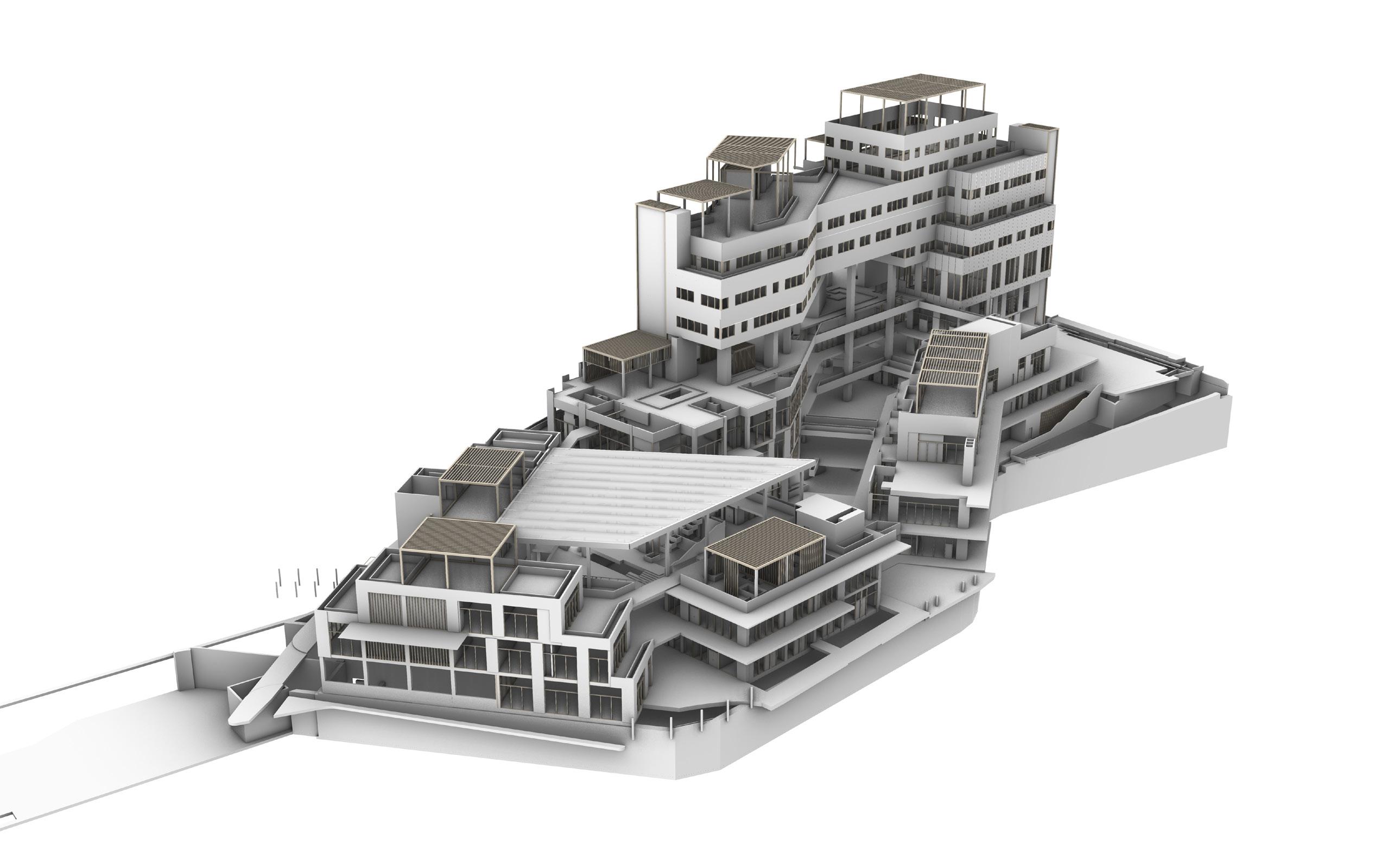
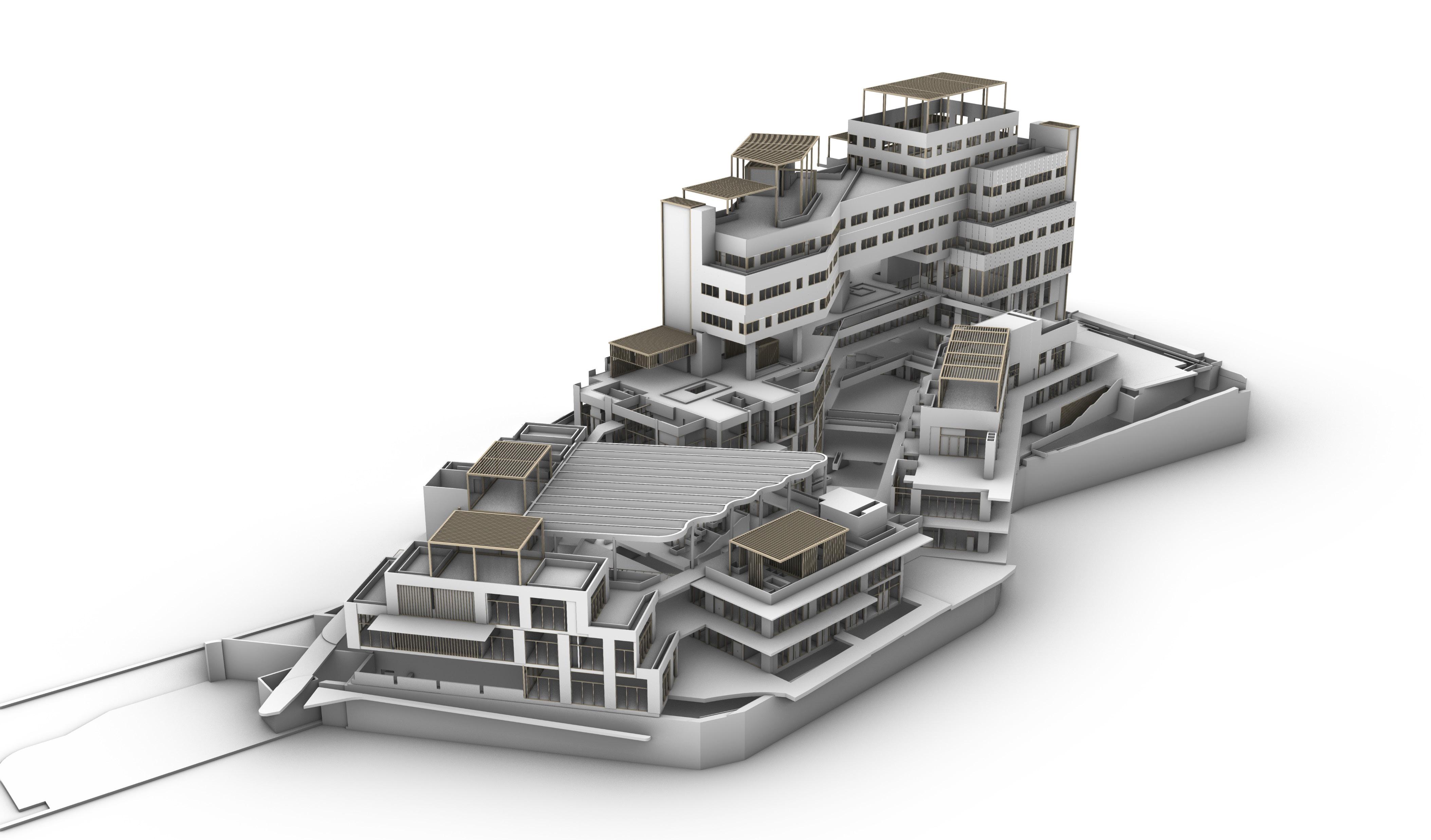
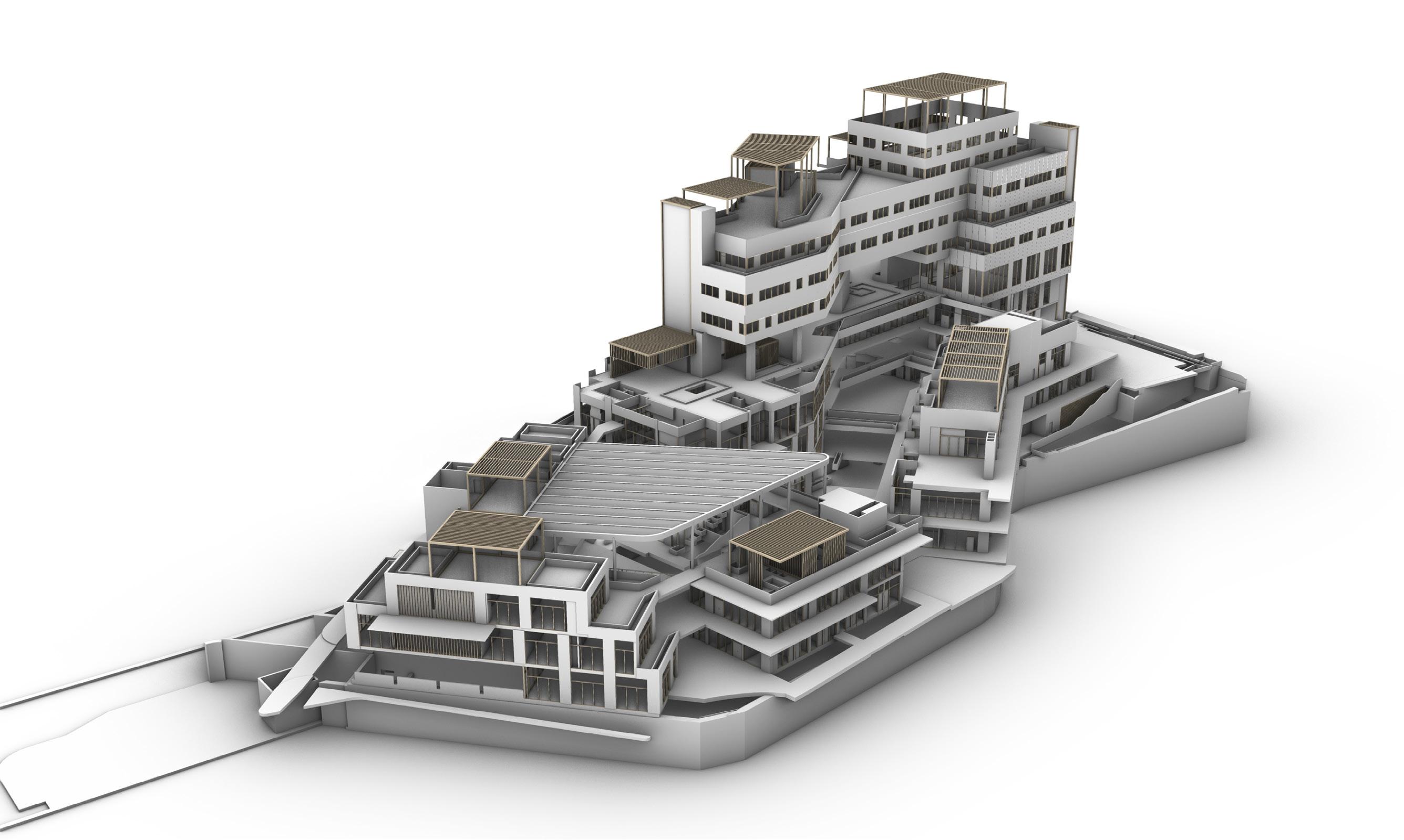
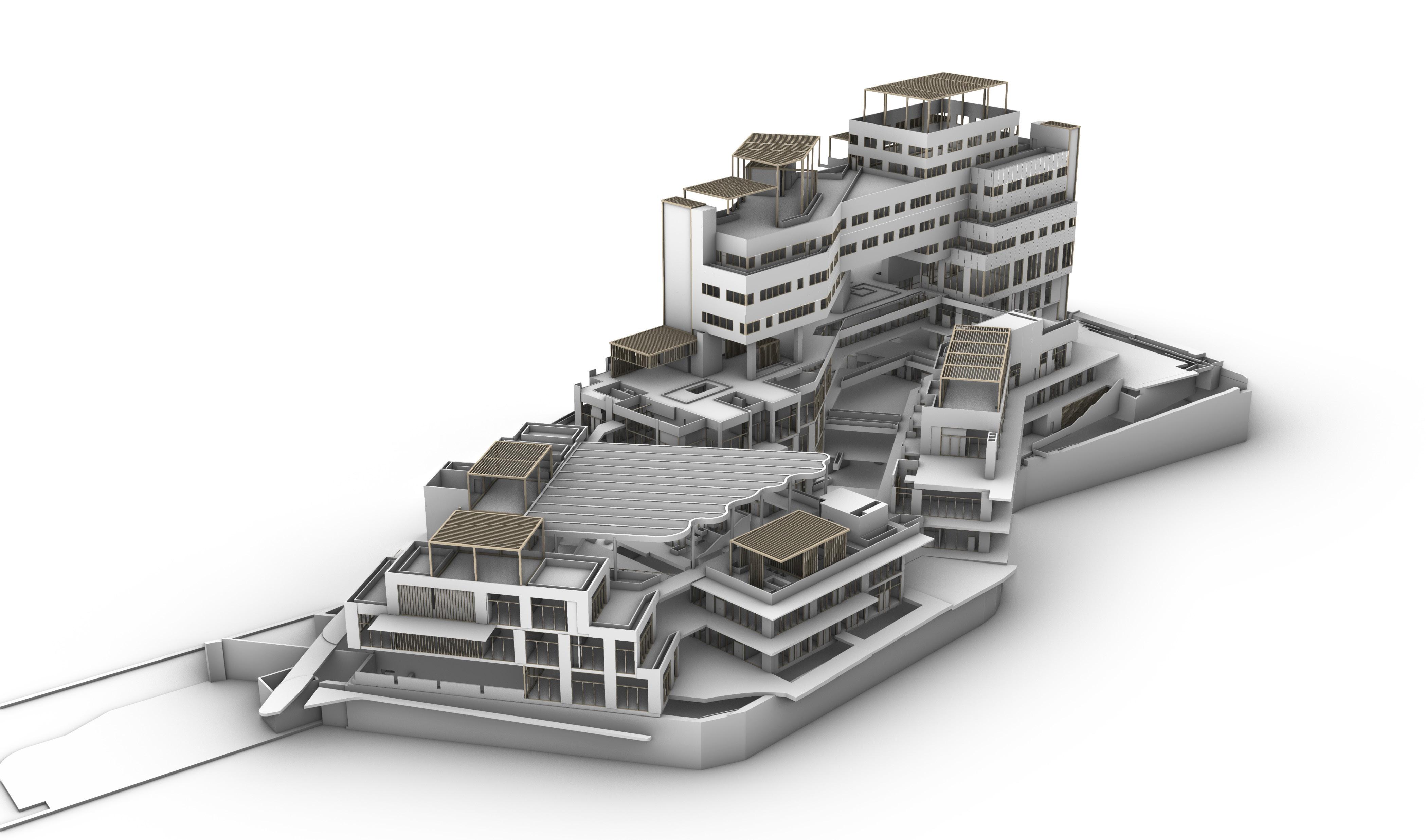
• Managed local projects including large and small food factories, a 16-storey office building in CBD and a landed house in varying phases, from design to completion.
• Conceptualised design and produced drawings for tender & construction with Revit and ArchiCAD.
• Prepared many authority submissions and am well-versed with local code requirements.
Sep 2020 - Apr 2021
Parametric Design Intern
Passage Projects
• Reduced construction cost and fabrication complexity of a complex geometry roof by parameterizing modules in Grasshopper, thereby cutting down the number of unique modules by 93%.
• Computationally analysed the deviation between the original design and proposed solution, to ensure adherence to engineering constraints.
• Built computational tools to streamline processes for design and structural analysis (e.g. Export Rhino/Grasshopper model to Oasys GSA).
• Produced 3D models, graphics and renders for design proposals.
Jan 2020
Front-End Developer Intern
Aural Aid Pte. Ltd.
• Built a web-based user interface that allows the creation and manipulation of polygons, calculation of attributes and cost estimations on the fly, and the export of generated information in a CSV file
• Programmed using JavaScript, HTML, CSS and Django (Python).
Jun 2019 - Aug 2019
Architecture Software Design Intern
Digital Blue Foam
• Learnt JavaScript on the job to contribute to the company’s code base.
• Created a code function that allows users to input freehand sketches as design constraints for the company’s building generation software.
• Interfaced with external APIs to generate geometric shapes for sun path visualisation.
• Researched and quantified attributes of a sustainable building, to incorporate into the product.
2020 - 2021
Education
Master of Architecture (Architecture and Sustainable Design)
Singapore University of Technology and Design (SUTD)
2017 - 2020
Bachelor of Science (Architecture and Sustainable Design)
Singapore University of Technology and Design (SUTD)
2015 - 2016
GCE ‘A’ Levels
Hwa Chong Institution
Awards
2019-2021
Sponsorship by Singapore’s Building Construction Authority
Nov 2015
Outstanding Award (Top Prize)
URA Challenge for the Urban and Built Environment (CUBE)
• Planned a designated area for enhanced liveability and connectivity in this national-scale workshop and competition organised by the Urban Redevelopment Authority.
Jan, Sep 2019
Design Participant
Workshop: Redesigning of Kindergarten in Rural Vietnam
• Surveyed the site’s architectural context, designed a preliminary concept with Vietnamese university students and presented to the partnering developer, Capitaland.
Jul 2017 - Sep 2017
Head of Logistics
PARK(ing) Day 2017
• Led a team of 3 to source and manage logistics for 7 design workshops which involved 8 secondary schools and polytechnics, and the main public event.
Oct 2014 - Apr 2017
Volunteer Leader and Sidewalker
Riding for the Disabled Association of Singapore
• Monitored and encouraged the weekly rehabilitation of the riders, who have disabilities like cerebral palsy, down’s syndrome and autism, through providing physical assistance and emotional encouragement.

Strong
Rhinoceros | Grasshopper (Python)
Adobe Illustrator | InDesign
Microsoft Powerpoint | Excel | Word
Familiar
Revit | ArchiCAD
Adobe Photoshop | Premiere Pro
Enscape
Languages
English and Chinese (spoken and written)
Python | Javascript
Travelling|Coding Music|Dance|Drawing
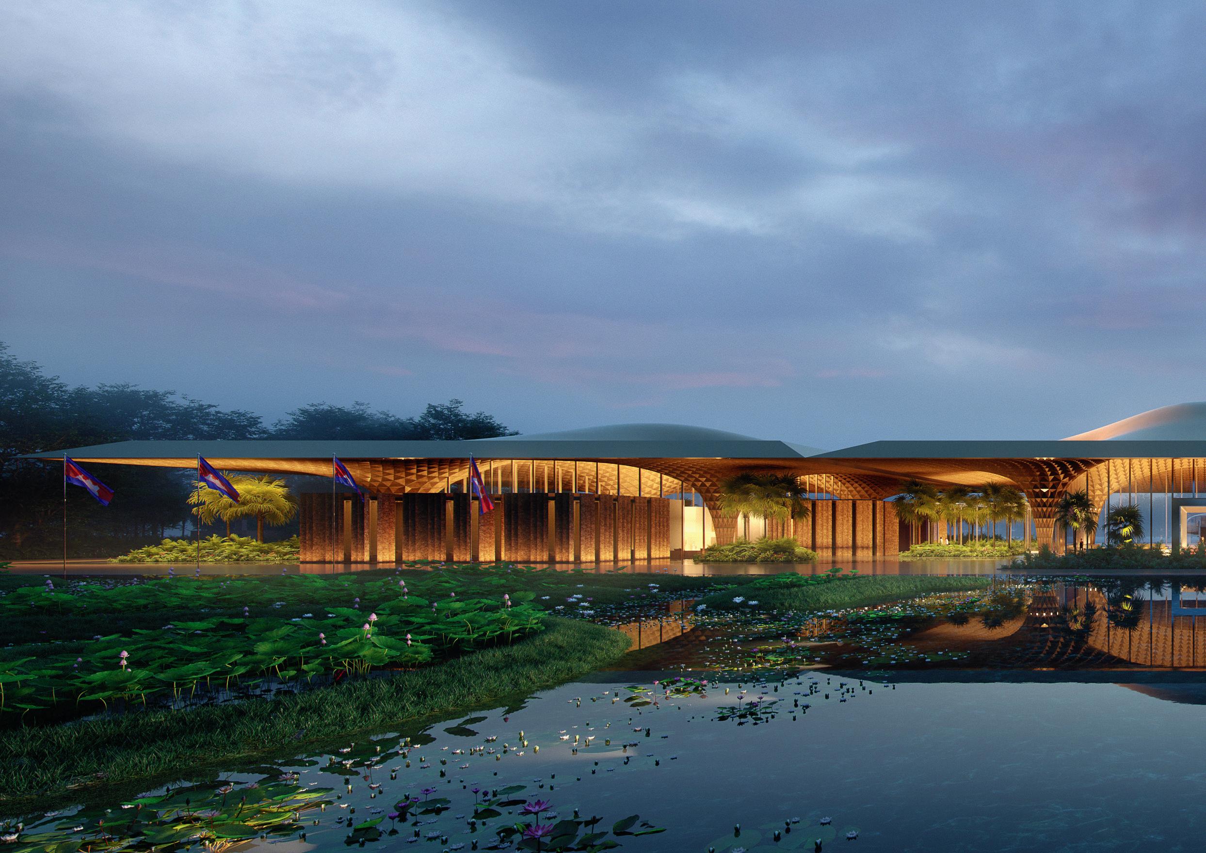
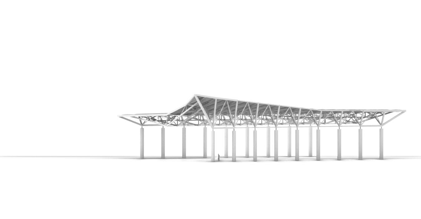
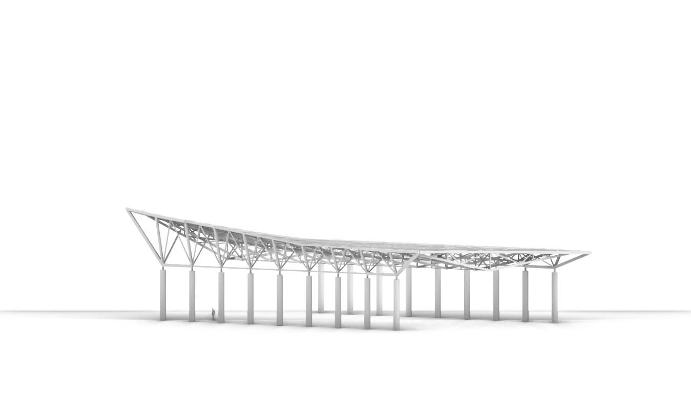
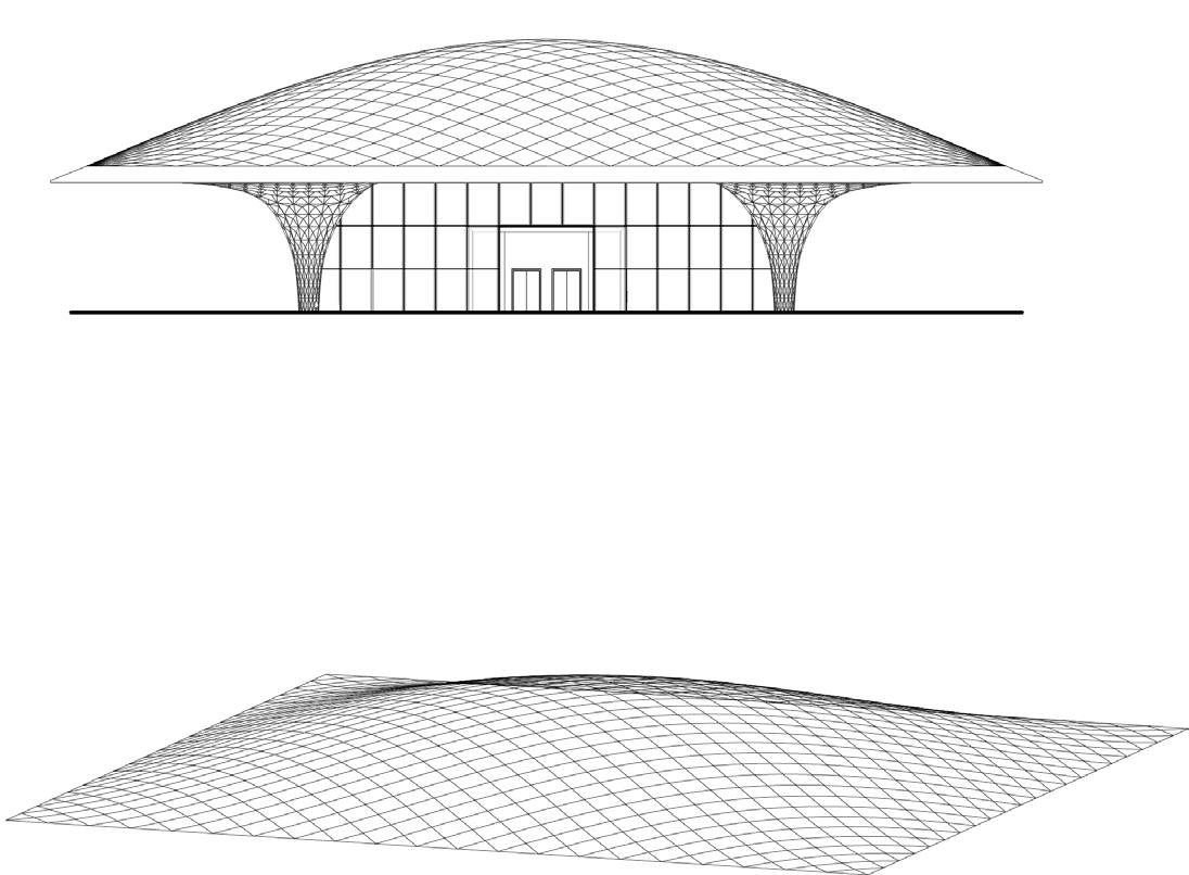
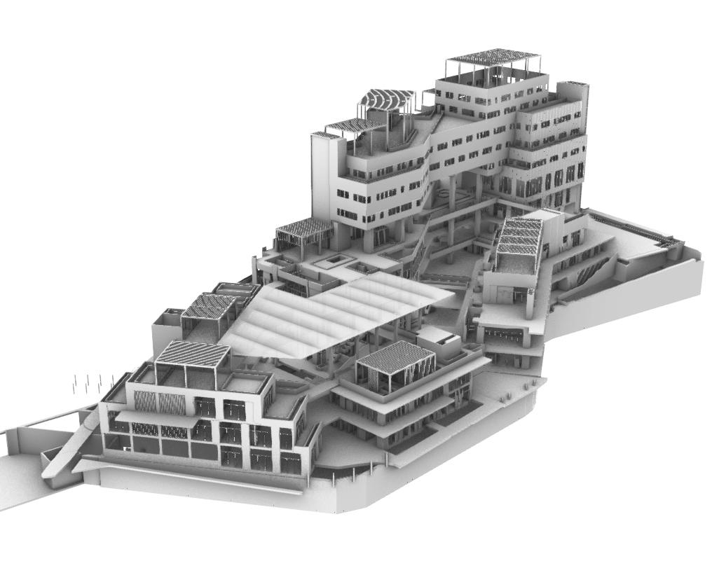
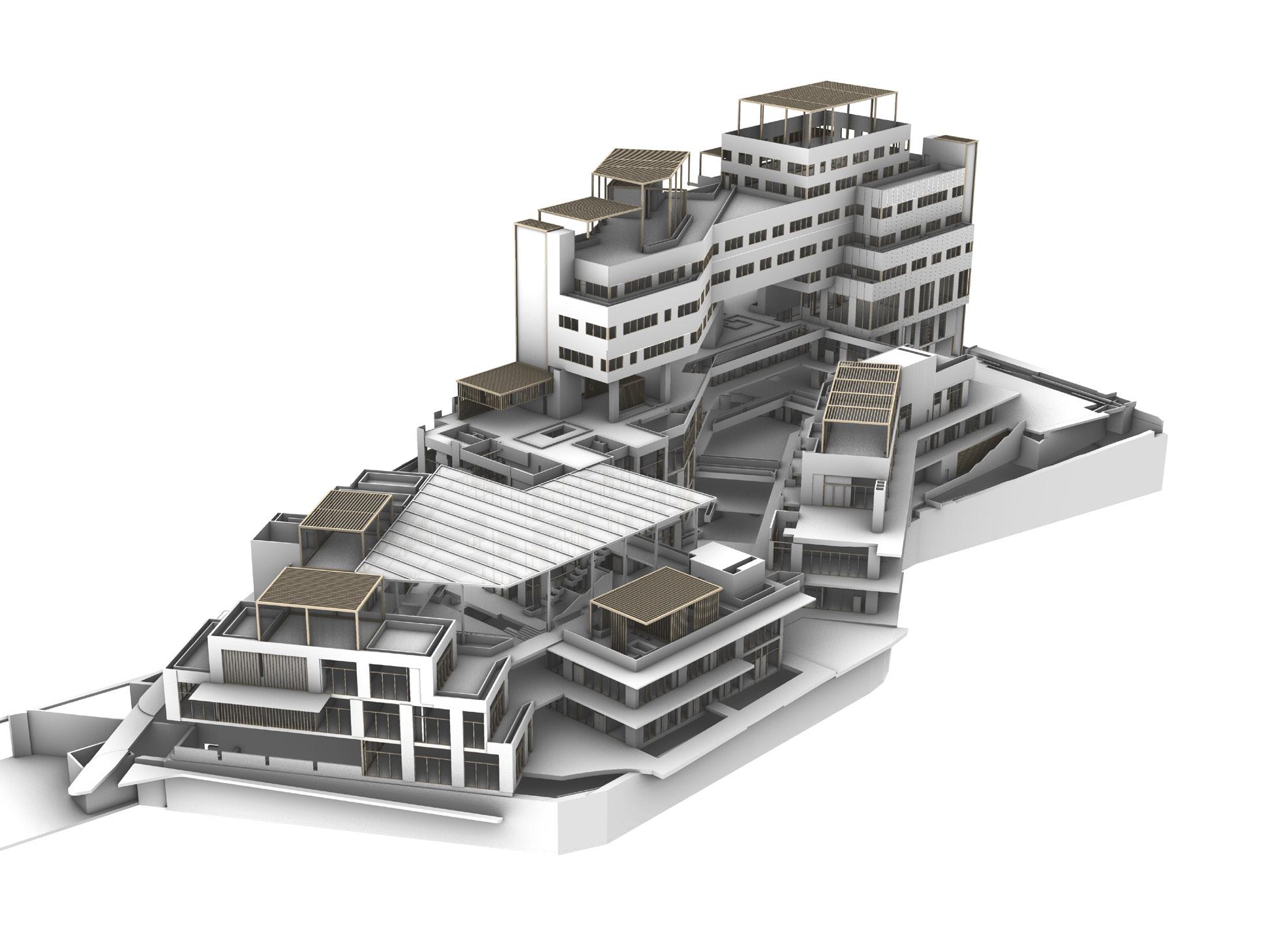
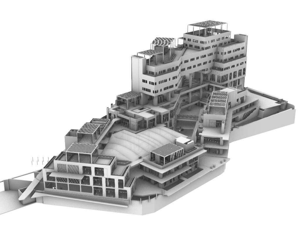
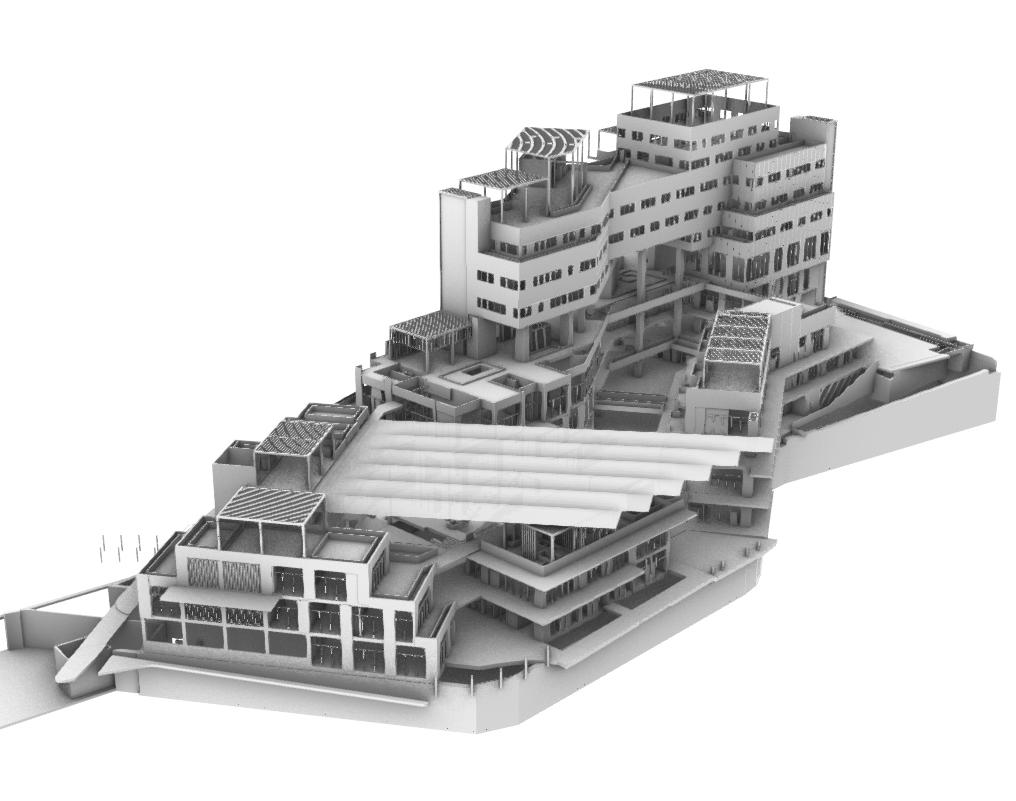
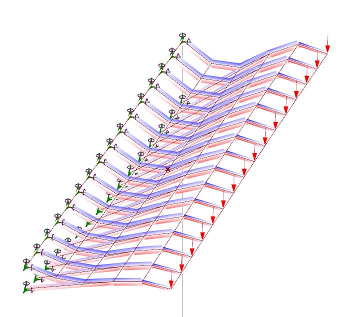
In my time at Passage Projects, I contributed significantly to the Value Engineering design proposal for a VVIP airport terminal in Cambodia. In particular, I reduced the number of unique modules in the roof by 90%, while retaining the design intent and adhering to engineering constraints.
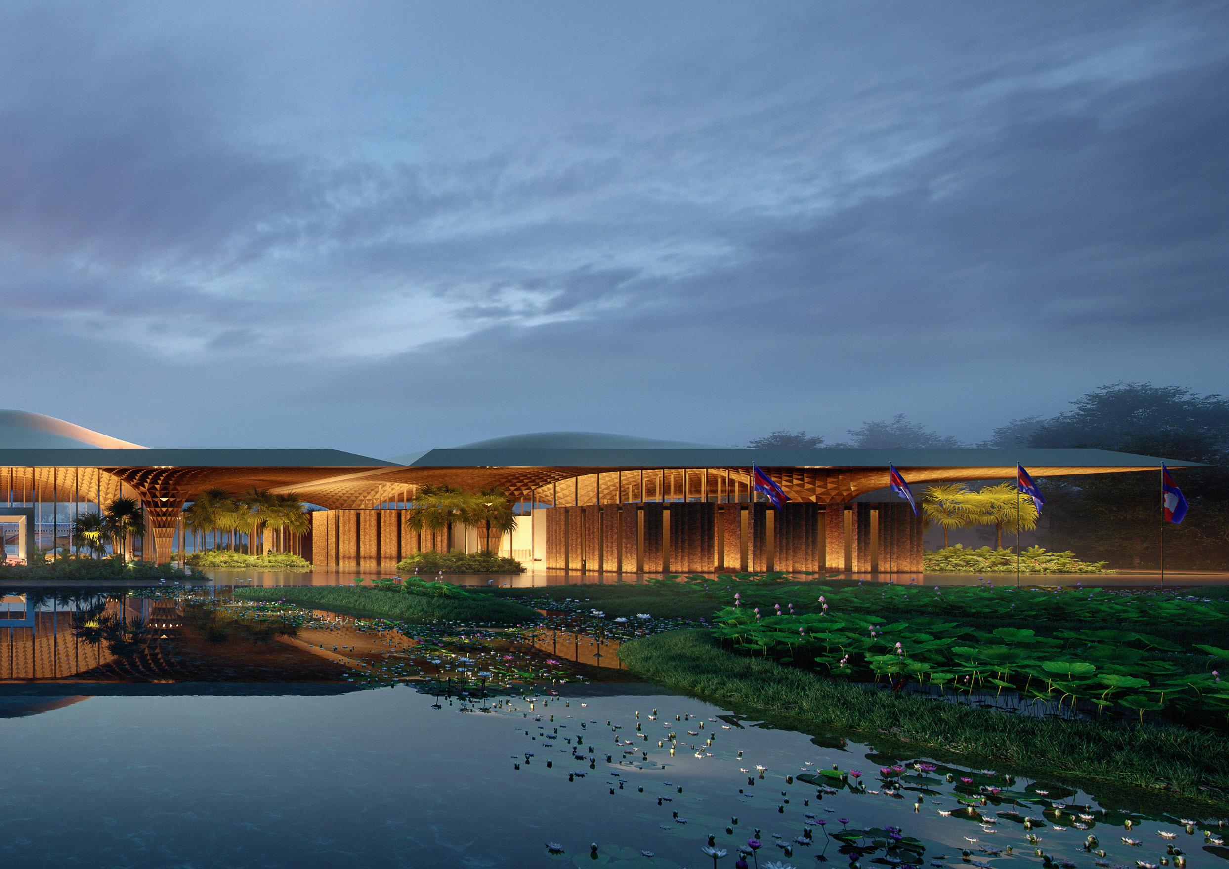
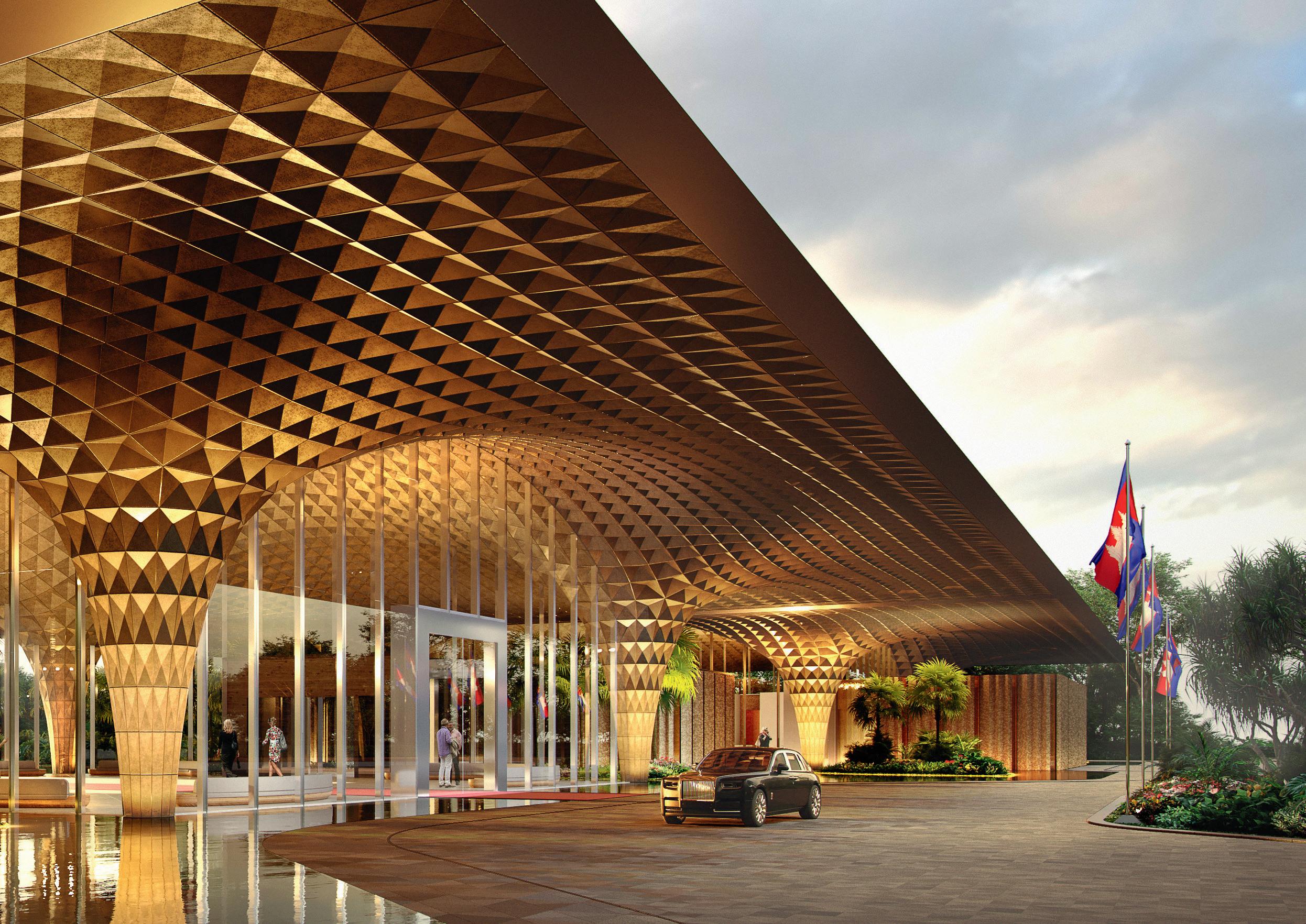
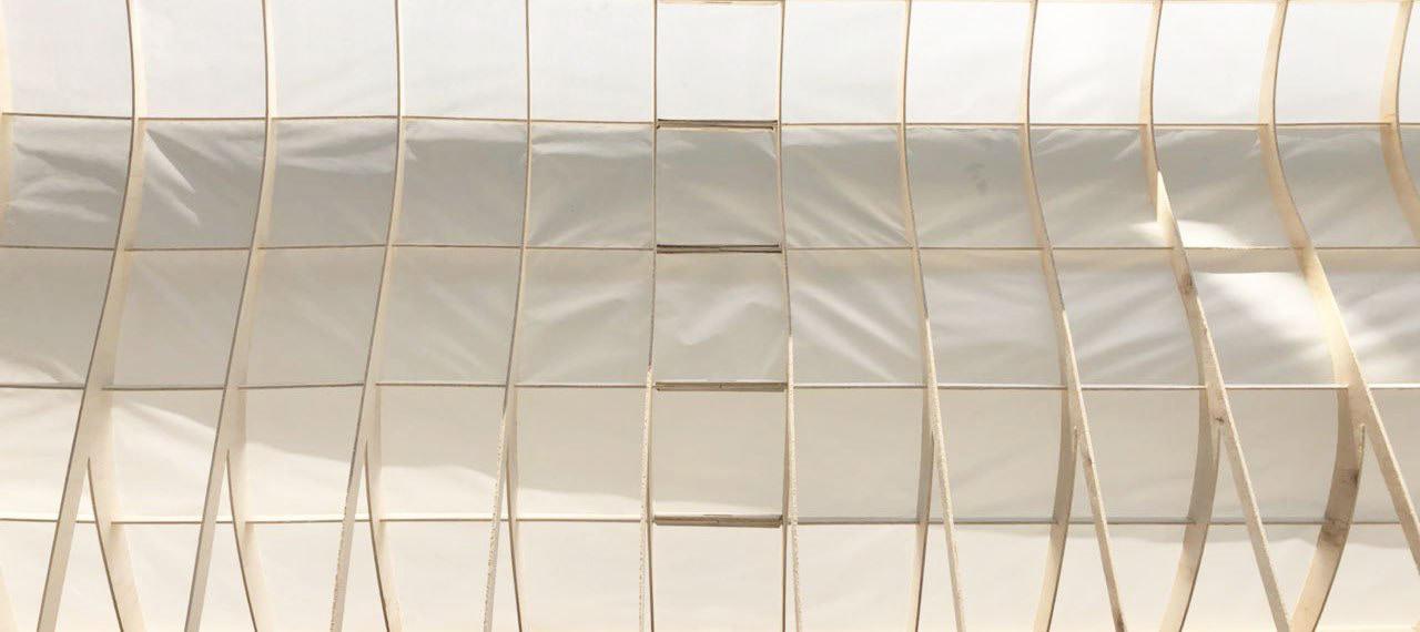
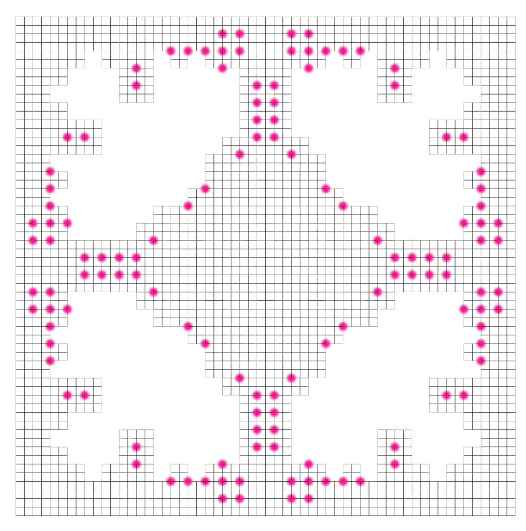
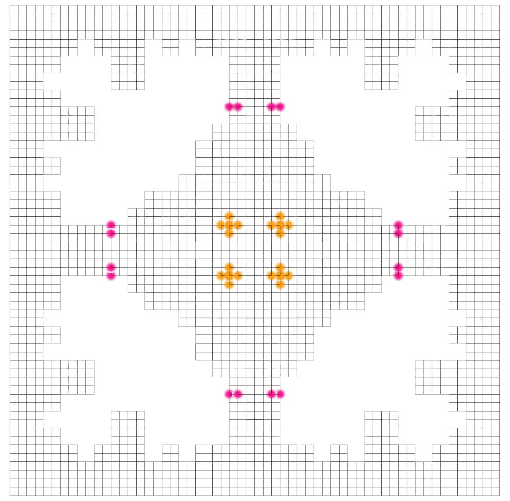
The original airport roof had a complicated soffit layer with over 500 unique pyramidshaped modules. To reduce cost of fabrication and improve craftsmanship, I explored various methods to reduce the number of modules.
Initially, we tried the most straightforward approach - to reduce the entire roof to only 2 types of modules (either half a pyramid or a full pyramid). This was done by using a single curve to define the whole roof. However, due to the drastic change to the shape of the roof, this method was not further pursued.
2 Module - Layout
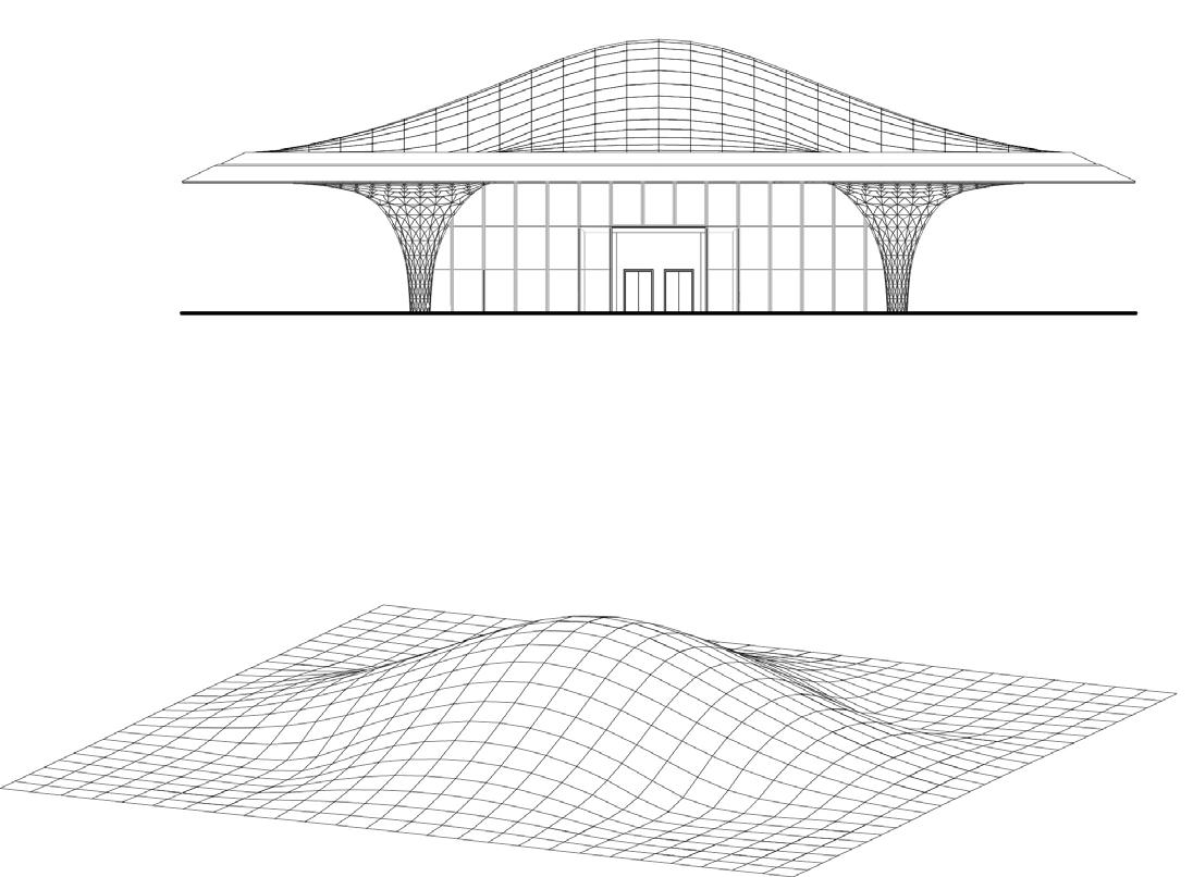
The shape of the roof drastically deviated from the original intent.
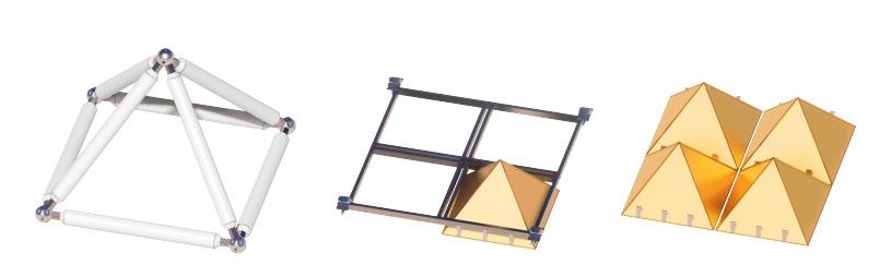
Space Frame Soffit Frame Pyramids (Soffit)Planarize Soffits
Creation of soffit Families
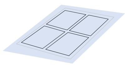
–Pyramids in one soffit frame are made identical, so joints are consistent and easier to fabricate
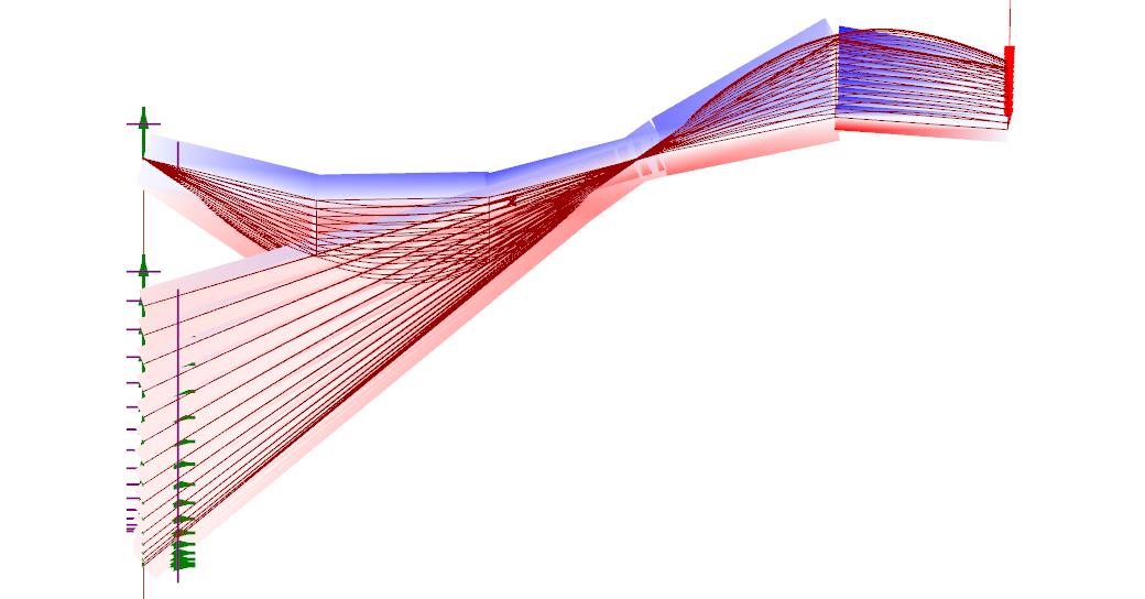
As the initial base design was done by another architect, I analysed the base model and adjusted it such that “families” of modules could be created, thereby reducing the numebr of unique modules by 93% (from 525 to 38).
Plan View
–Repeated modules improves craftsmanship, reduces cost
Creation of soffit Families
Creation of Soffit Frame Families
60% DD Soffit Frame
Base Quad
–Pyramids in one soffit frame are made identical, so joints are consistent and easier to fabricate
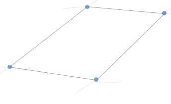
Individual pyramids and soffit frames are non-planar in 60% DD. As such, the size of each plate and angle of each joint is distinct from another. Unique modules are complicated and expensive to fabricate.
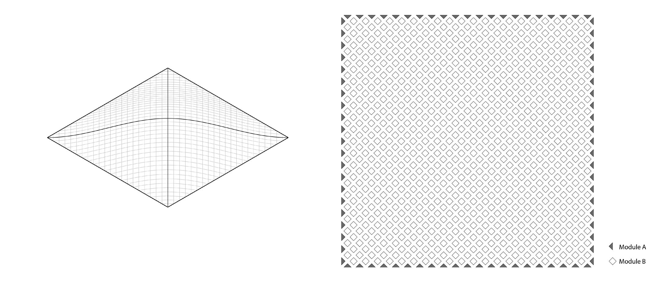
Planarization of soffit frames is proposed, so that the joints in each frame can be the same. This also allows the 4 pyramids in each soffit frame to be identical, reducing the number of unique modules to a quarter of the original design.
–Pyramids in one soffit frame are made identical, so joints are consistent and easier to fabricate
Frame Families
Use average plane to planarize module
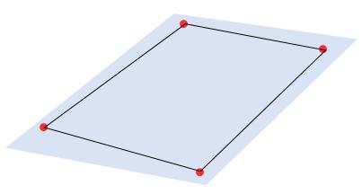
Proposed Planar Parallelogram
Soffit Frame
45
Implications
Planarize Soffits
Planarize Soffits
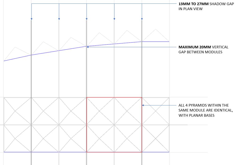
Averaging the plane of the soffit frame results in deviations in the shadow gap and creates a vertical gap between some soffit frames. Modules near the columns which deviate too much are removed from the modularization process (remain unchanged from 60% DD)
Individual pyramids and soffit frames are non-planar in 60% DD. As such, the size of each plate and angle of each joint is distinct from another. Unique modules are complicated and expensive to fabricate.
Individual pyramids and soffit frames are non-planar in 60% DD. As such, the size of each plate and angle of each joint is distinct from another. Unique modules are complicated and expensive to fabricate.
This proposal sees deviations in the shadow gap of ±7mm from the original size of 20mm, while the maximum vertical gap attained is 20mm. In the scale of the large roof, this deviation is deemed to be minimal.
Planarization of soffit frames is proposed, so that the joints in each frame can be the same. This also allows the 4 pyramids in each soffit frame to be identical, reducing the number of unique modules to a quarter of the original design.
Planarization of soffit frames is proposed, so that the joints in each frame can be the same. This also allows the 4 pyramids in each soffit frame to be identical, reducing the number of unique modules to a quarter of the original design.
Implications
Implications
Averaging the plane of the soffit frame results in deviations in the shadow gap and creates a vertical gap between some soffit frames. Modules near the columns which deviate too much are removed from the modularization process (remain unchanged from 60% DD)
Deviation Analysis
Deviation (Vertical Gap)
Averaging the plane of the soffit frame results in deviations in the shadow gap and creates a vertical gap between some soffit frames. Modules near the columns which deviate too much are removed from the modularization process (remain unchanged from 60% DD) Deviation Analysis Deviation (Vertical Gap)
This proposal sees deviations in the shadow gap of ±7mm from the original size of 20mm, while the maximum
Proposed Planar Parallelogram
Pyramid Base
The original modules were not planar, resulting in an inevitable large volume of modules. First, I planarised the modules and adjusted the pyramids to be perpendicular to these planes. This also approximates each frame of 4 adjacent pyramids to be identical.
Deviation (Shadow Gap)
Due to the change in direction of pyramids, there was a +-7mm deviation from the originally consistent 20mm shadow gap between modules.
Deviation Analysis
Deviation (Vertical Gap)
15MM
15MM to 20MM
Vertical gap between adjacent pyramids
Deviation (Shadow Gap)
13MM to 15MM
Shadow gap size between adjacent pyramids
25MM to 27MM
Shadow gap size between adjacent pyramids
25MM to 27MM
13MM
Shadow gap size between adjacent pyramids
25MM to 27MM
Shadow gap size
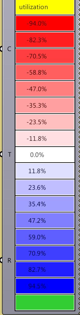
A Grasshopper tool was created to highlight deviations, colour-coding the deviations by userdefined values. In this case, it was deemed that the number of modules exceeding a +-5mm deviation was minimal, hence acceptable.
Step 3) Parameterise Modules & Approximate into Families
There are multiple parameters in the roof geometry, as set out as below. Each of these parameters are rounded off to a value (“thresholds of tolerance” that can be adjusted parametrically) and approximated into families of modules, to reduce the numebr of unique modules.
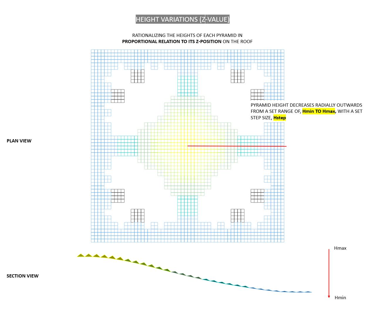
The height of the pyramids are set out in two different ways, producing two types of overall roof profile with slight difference in efficiency.
Length of Pyramid Edges, L = NEAREST A mm
Height of Pyramids, H = Nearest B mm
Angle between Edges, X = Nearest C °
where A, B and C are thresholds that can be changed parametrically.
Base model: A = 10, B = 50, C = 1

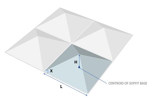
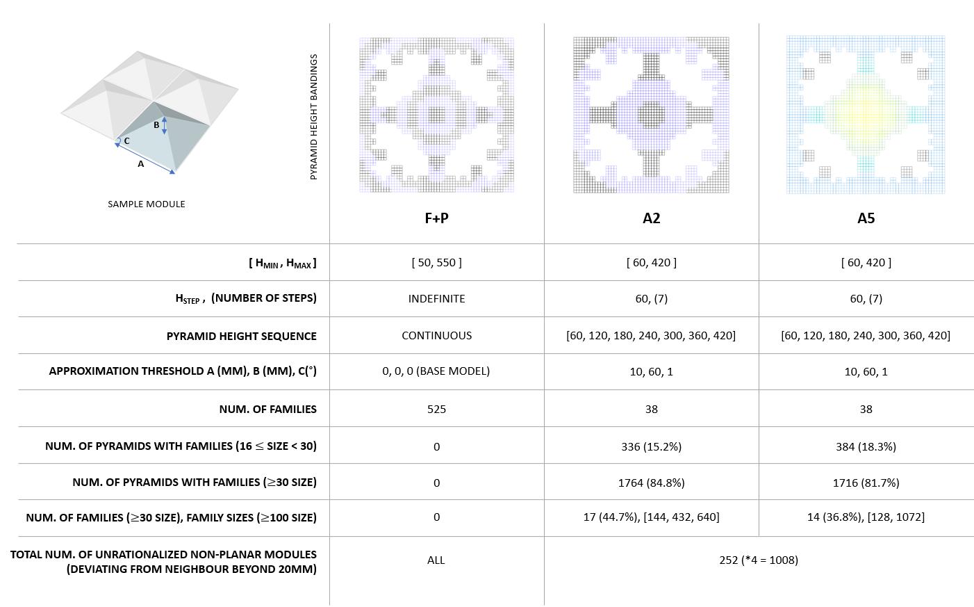
With this approach, the number of unique modules was reduced from 525 to 38 (93%), while retaining the design intent of the roof.

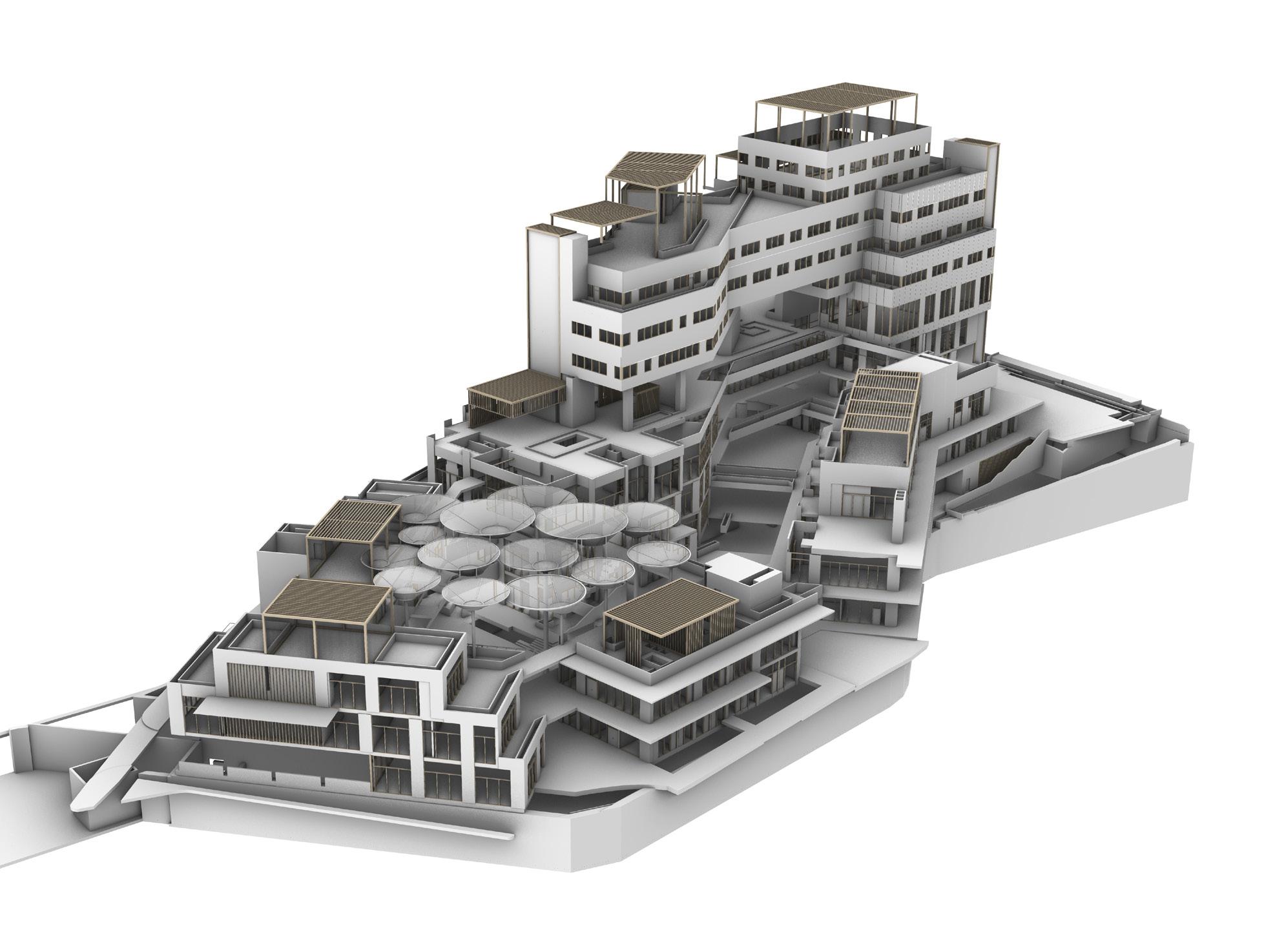
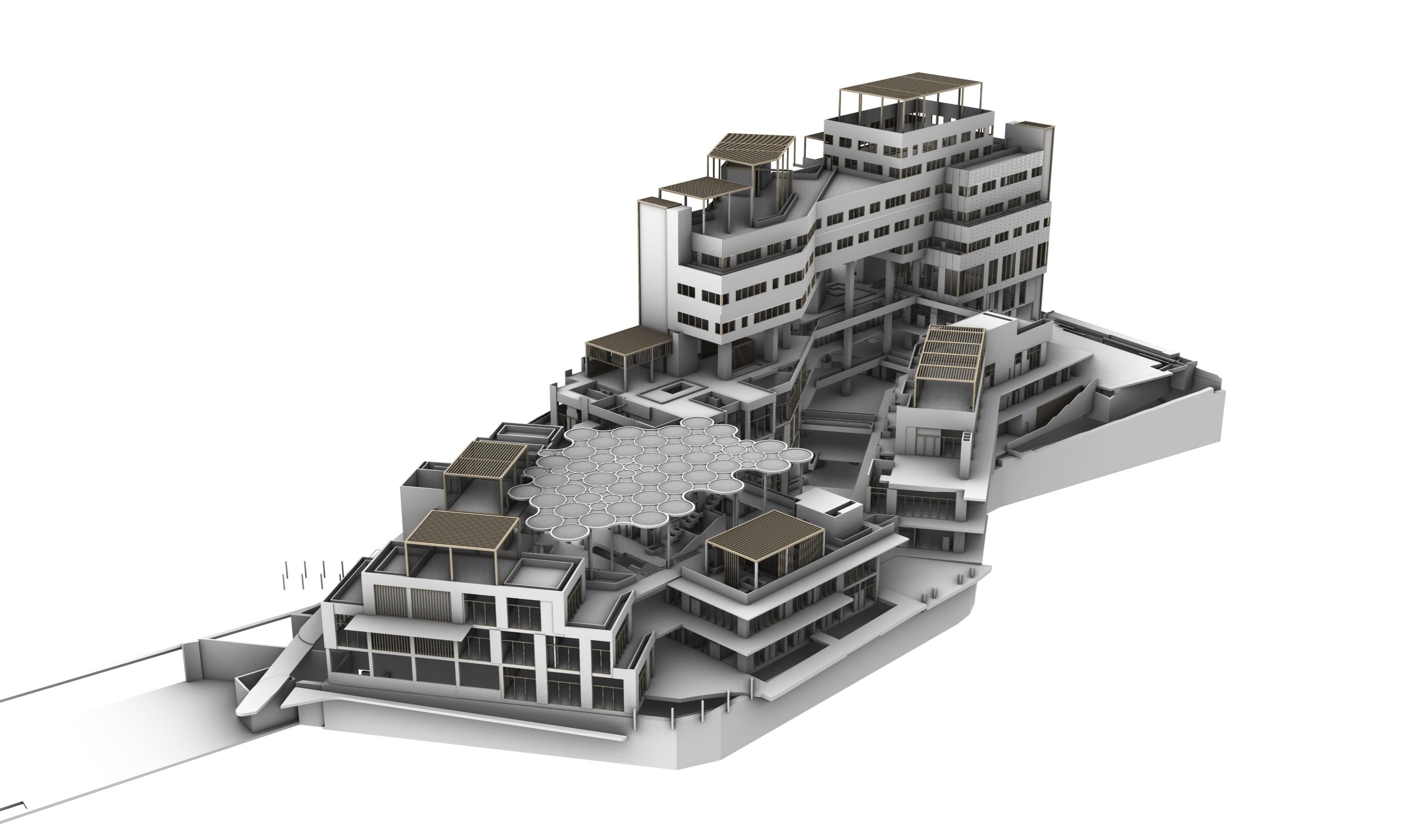

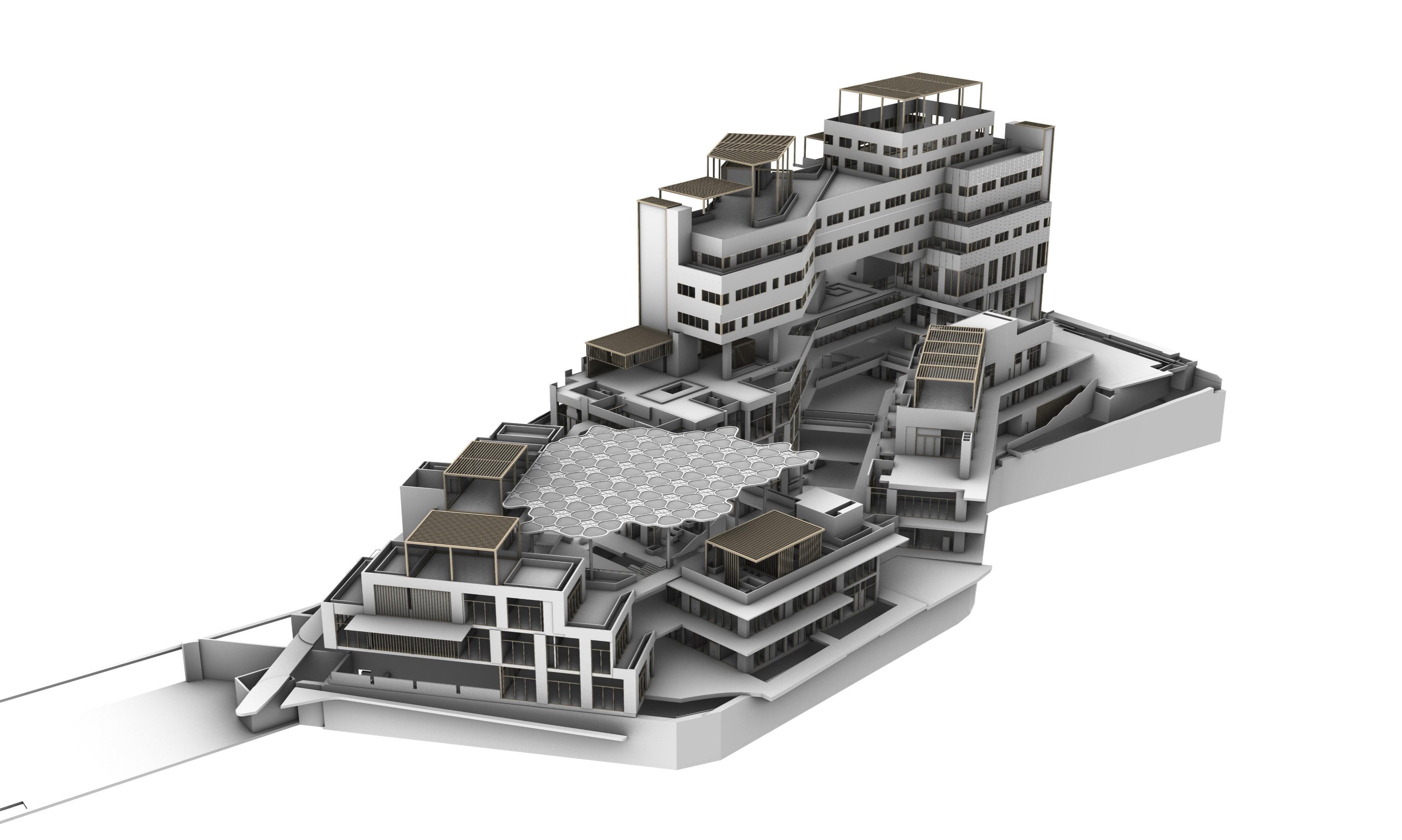
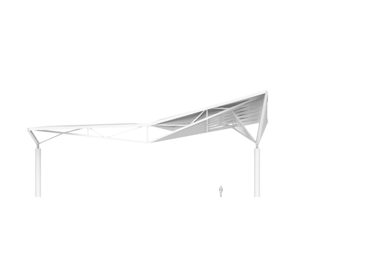
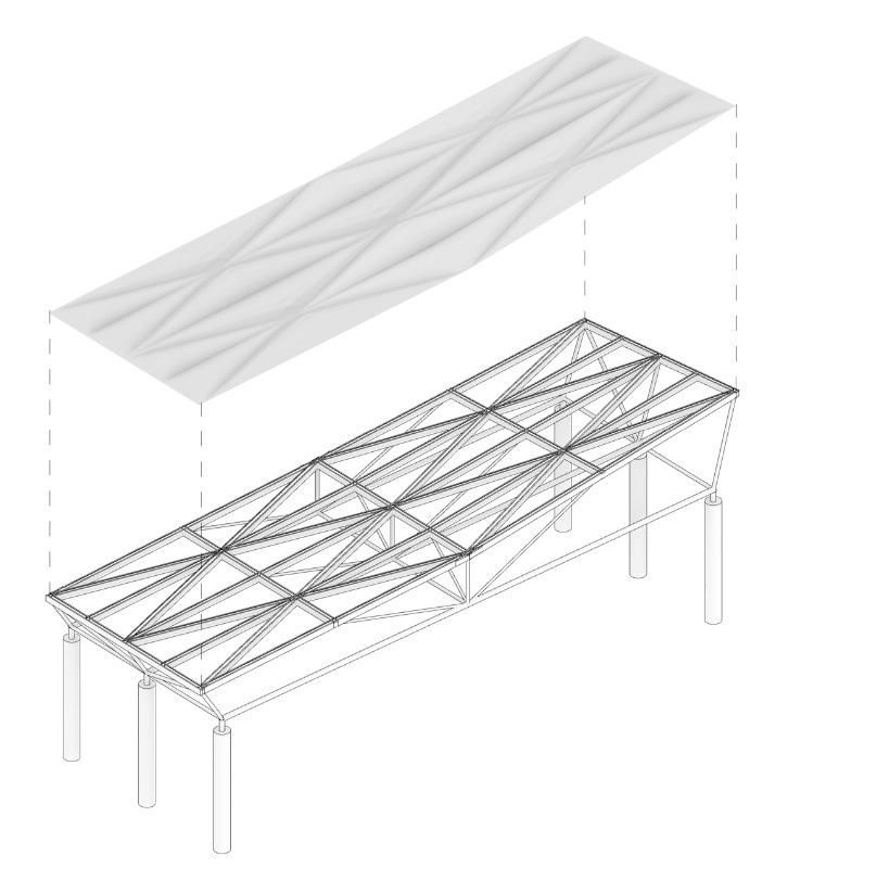
A series of design iterations for a canopy was developed to shelter rain and sun from the central courtyard of a mixed-use development in Singapore. Each design stems from the base design brief, which requires the use of a steel frame structure to hold ETFE-cushions.
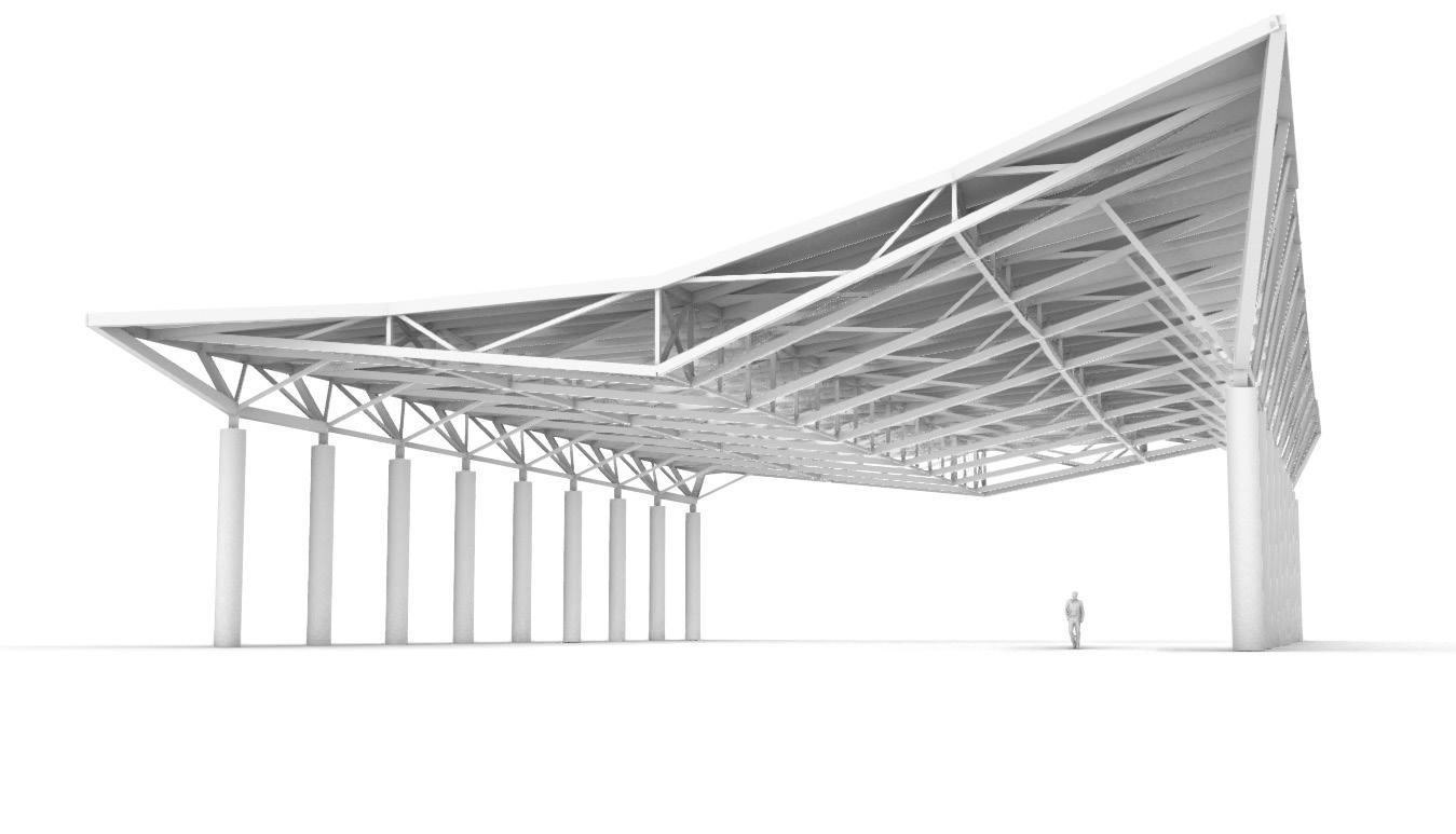
Structural design proposal for a sports court in Hong Kong. For this project, I modelled the proposal in Rhino and produced drawings and renders for presentation.
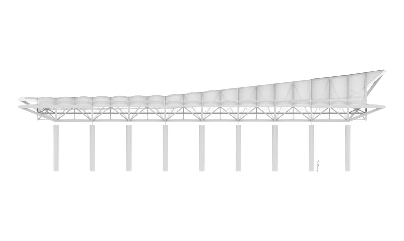
 Front Elevation
Side Elevation
Front Elevation
Side Elevation
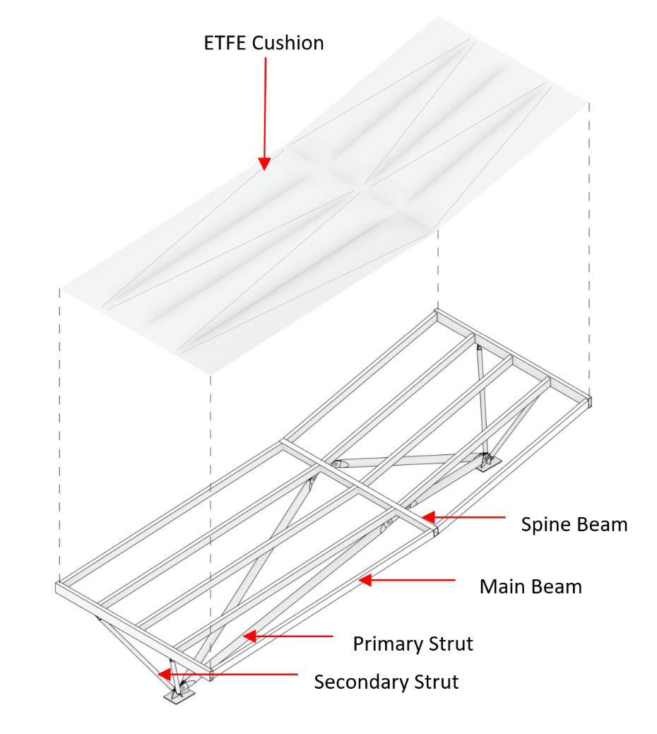
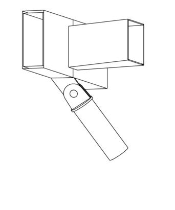
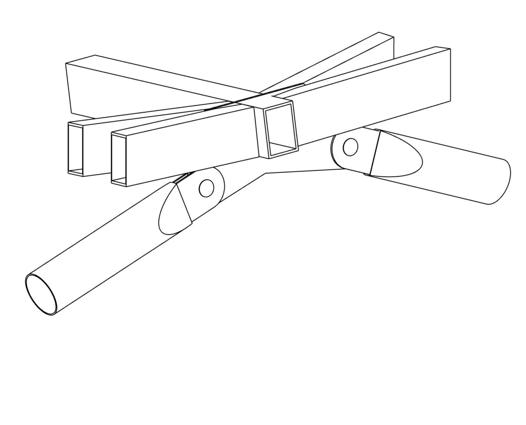
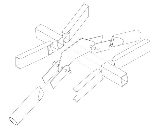 Connection at Spine Beam (Exploded View)
Connection to Edge Beam Connection to RC Pedestal Connection at Spine Beam
ETFE Cushion
Spine Beam
Main Beam
Primary Strut
Connection at Spine Beam (Exploded View)
Connection to Edge Beam Connection to RC Pedestal Connection at Spine Beam
ETFE Cushion
Spine Beam
Main Beam
Primary Strut
Base Scheme
Alternative Proposal: 3m Rectangular Cushions with print to replicate triangulation
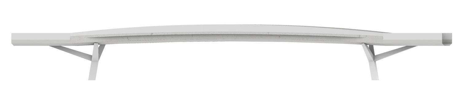

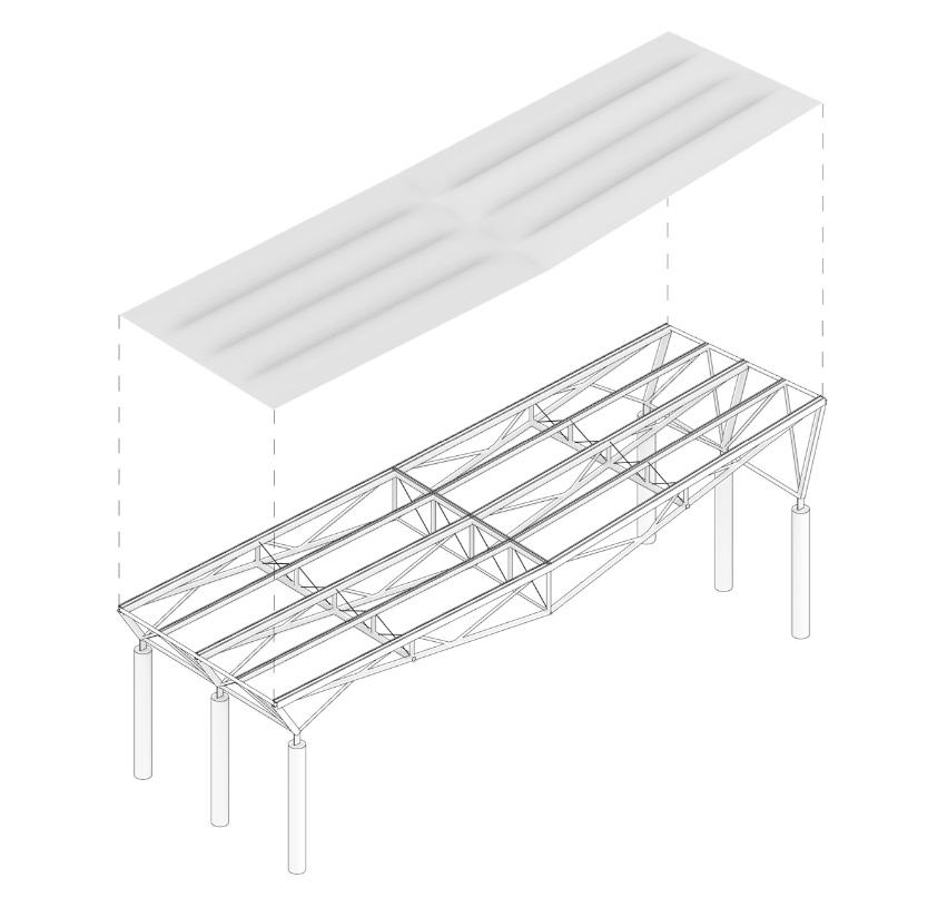
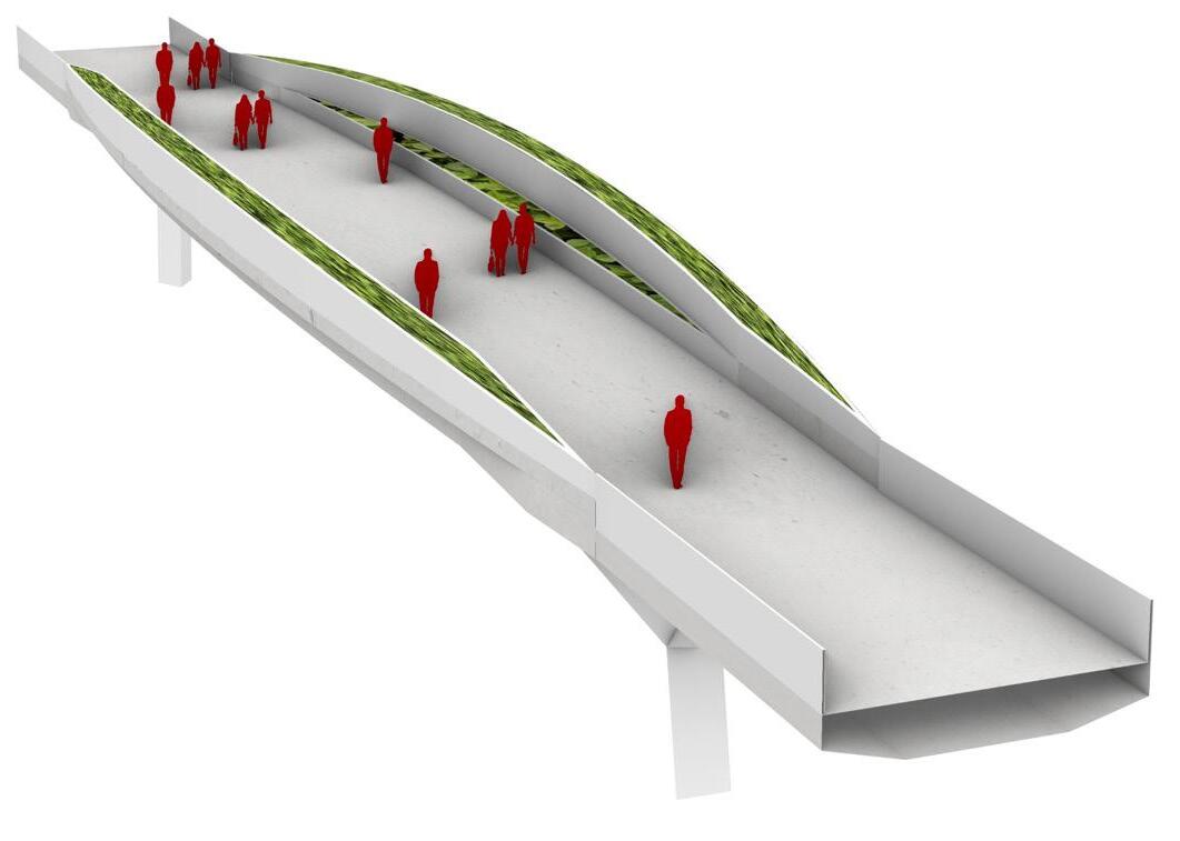
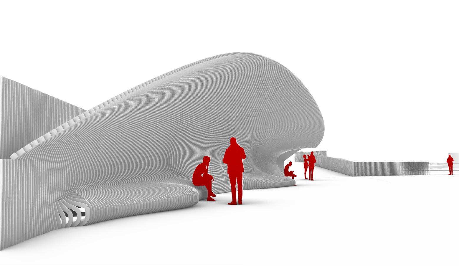
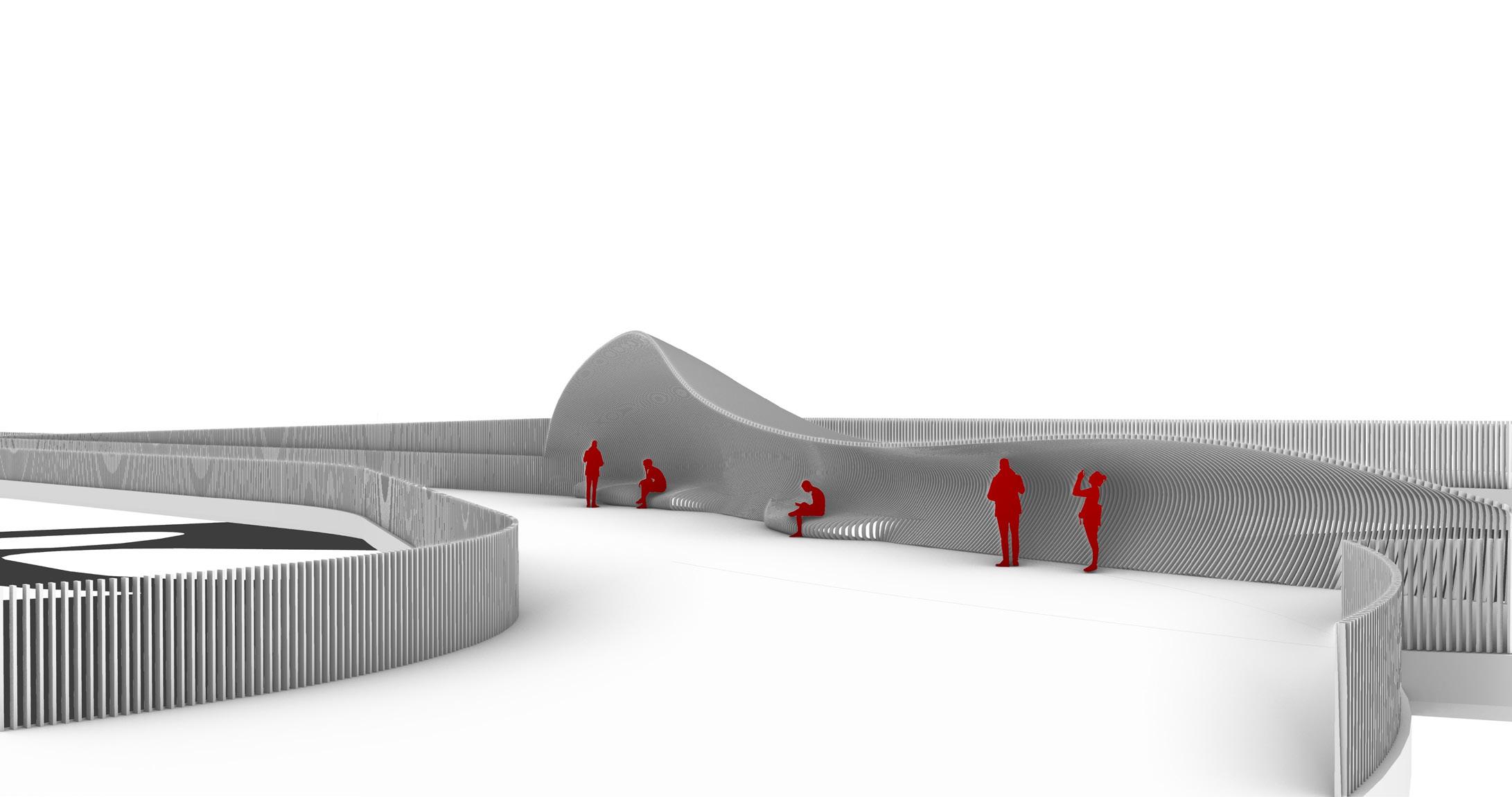
As part of a urban planning project in Shenzhen, China, we proposed various structural profiles while incorporating public spaces for the elevated footbridge. Section
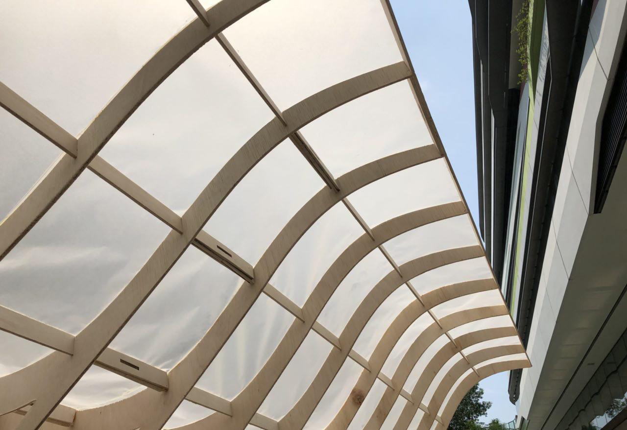
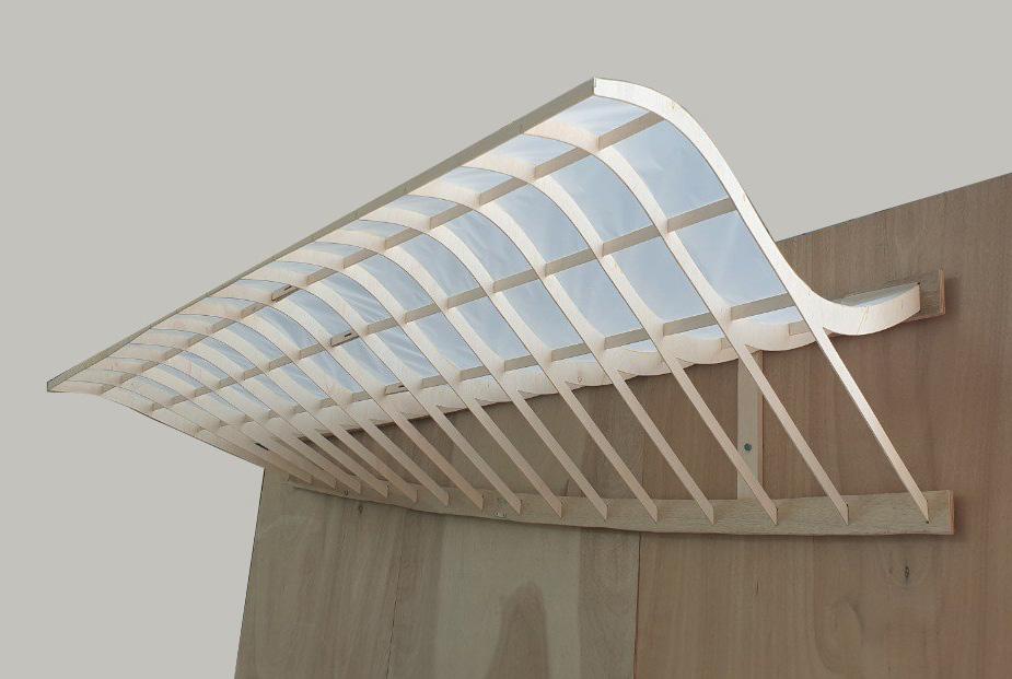
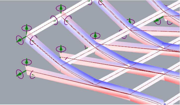
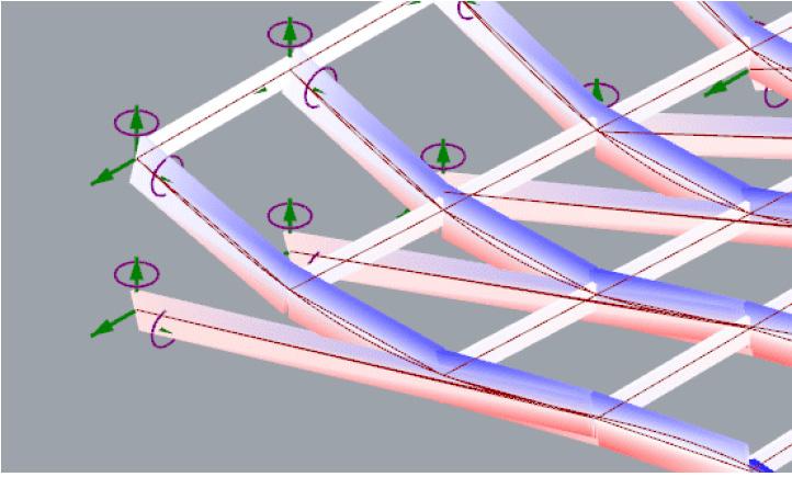
Komorebi describes the poetic beauty of sunlight filtering through leaves. Seeking to design and fabricate a canopy that is subtle, elegant and structurally functional, we took inspiration from the simplicity of Komorebi.
For this project, I designed a Grasshopper tool to parametrically generate a form for the canopy and used Karamba for structural analysis. This project was done in a team of 4, over the course of 6 weeks.
0.65cos(x+1.3) + 0.65sin(2.4y+6) -abs(0.3cos(1.2x+5)sin(6.5y+3.6) abs(cos(0.6x + 8.4) sin(2.5y + 2.6)) -abs(-0.51cos(3.3x+ 4.2)sin(6.4y+2.8) abs(-0.26cos(1.7x + 7.3)sin(6.2y+3.5)
Vertical Self & Live Loads
Total of 70kg vertical load spread across all points
Lateral Wind & Live Loads
Self loads are imposed by the weight of the materials. Vertical live loads factor for the possibility of the canopy being pulled from below or hung onto by users.
Point loads in the Karamba are modelled for the extreme scenario where only the edges of the canopy are pulled at.
Lateral live loads account for the possibility of the canopy being pushed in the horizontal direction by users.
Total of 1kg horizontal load spread across all points
There is little lateral live load expected, except for strong winds.
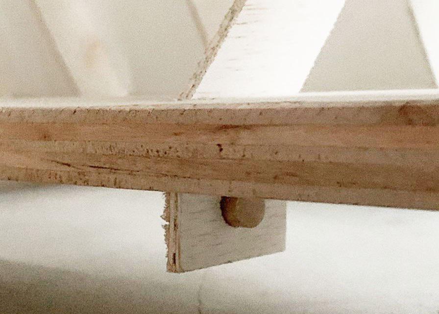
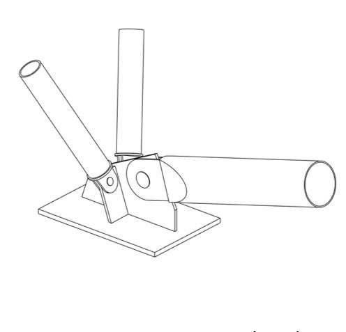
The Karamba model showed that there were additional tensional forces on the structure when the structure was not allowed to rotate freely from the back plank. Hence, to release tension in the structure, we introduced the loose hinge-dowel joint to allow rotation while fixing translation.
Without dowel joint (Rx fixed)
With dowel joint (Rx unfixed)
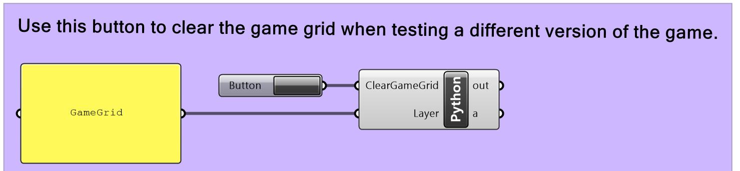
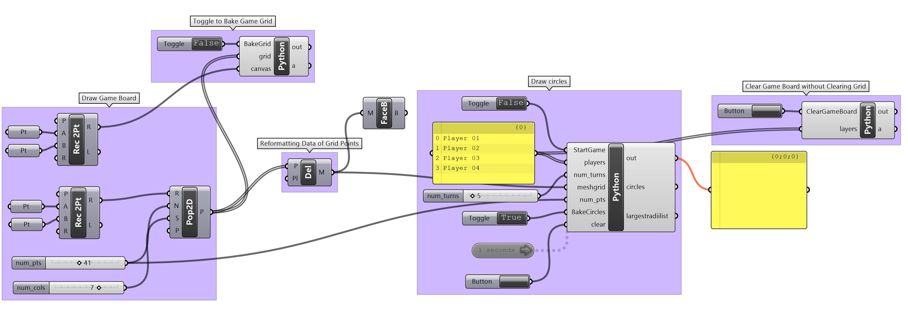
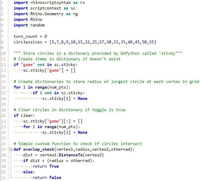
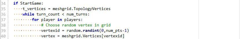
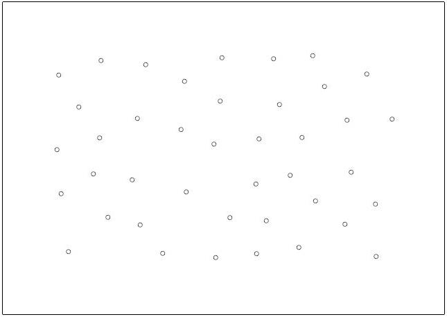
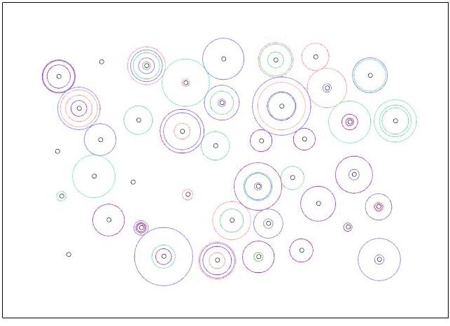
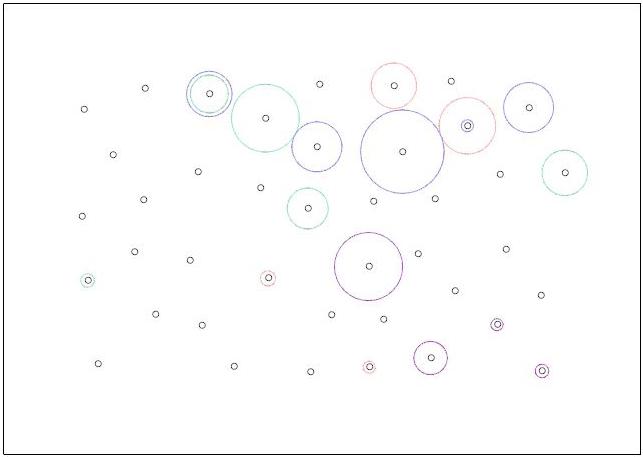
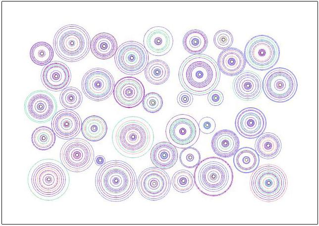
One of my first few Grasshopper projects, this code simulates a circle-drawing game to create a live artwork. When the programme runs, concentric circles are drawn onto points on a canvas over time. Depending on the changing parameters, different results are produced with varying paces of growth or arrangement of points. It can be exciting, intriguing, or simply therapeutic to watch.
Some things this project taught me was to create a memory system using sticky variables, and to access Rhino scriptcontext (to directly manipulate Rhino objects in Grasshopper, or automatically bake Grasshopper geometry into Rhino).
Thank