














In 1981, I started working with Eddie Jordan.
We had been neighbours at Silverstone for a couple of years in some of the very first workshop rental units there. I’d been looking after the Brazilian Ribeiro brothers and he had his F3 car there.
Eddie had decided he’d probably be a better wheeler dealer and team manager than a driver, after only modest success in F3. So, we teamed up to form Eddie Jordan Racing. Despite the court jester external persona, Eddie is seriously shrewd and clever. How else do you become head of securities at the Bank of Ireland in your 20s, run a successful F1 team and escape the ‘shark pool’ with millions in the bank?
What Eddie knew most about, given his background, was how to borrow money. In fact, during the Eddie Jordan Racing era he actually ‘owned’ the Northampton branch of the Allied Irish Bank. They daren’t pull the plug on his borrowing or the branch would go down. It therefore came as no surprise to me to hear the branch manager became financial director of Jordan F1 in 1990.
In ’81, we ran Formula Ford and an F3 car for whoever had some money, or whoever Eddie could find money for.

By ’82, we were established enough to compete in a whole season of F3 with James Weaver and a pair of FFs as well. Eddie sorted a deal with Yokohama that we would get free tyres and some travel costs to represent the tyre manufacturer in European round races. We managed to win each of the rounds we entered.
With James driving and the ridiculously sticky tyres, we had a winning and, better still in Eddie’s eyes, a paying combination. The car sat under the podium at Nogaro after winning the race and, when the Champagne stopped flowing, it took five of us to push the car away as it lifted the tarmac stuck to the tyres. The Yokohama tyres were that sticky.
It wasn’t an easy time, though, and we had to wait until Yokohama agreed to pay for the next race before we could move on to Jarama in Spain. We won that one, too.
Eddie was always on the look out for quick drivers, and one guy who was blitzing the field in FF2000 was a certain Senna da Silva. He was invited to come and try our F3 car at Silverstone.
James had put the car on pole the weekend before, so Ayrton knew he was testing a quick car, and I was the first person to strap Senna in an F3 car. He was using James’ seat and we used a couple of sheets of carpet underlay to give him a comfortable (temporary!) driving position.
On his very first run in an F3 car, Ayrton equalled James’ pole time within 15 minutes, and then proceeded to tell us what he needed to go quicker still. He said the aero was great, but we needed to find more mechanical front grip in the slower turns.
I still have the lap sheets from that day.
Martin and Eddie set about finding some money to allow us to compete, and Martin was given a few thousand by his mentor, Tom Walkinshaw, in the form of a GPA helmet deal, for which Tom was the importer.
Eddie didn’t like the idea of going to meet Tom so, as the race engineer (!), I was dispatched to pick up a cheque from Kidlington. That was my first ever meeting with Tom in his office and I was handed a nice, large cheque. As is turned out, it would not be my last.
The first nine races of 1983 were painful. At each one we were beaten into second place by Senna, but Martin and I were learning more about the car and each other all the time. Then came the combined British and European round in June at Silverstone where we both decided to forgo British points and go for overall victory on European tyres.
This was the turning point of the season. We had the advantage of knowing the tyres from the previous year and Martin grabbed the opportunity with both hands. He took pole and won the race, while Ayrton crashed trying to keep up.
The following year, Senna became the opposition as he had chosen to take his Brazilian backing to WSR as they had already been British F3 champions three times.
Eddie agreed to run the talented but underfunded Martin Brundle instead. Martin had a season of F3 and a couple of wins behind him, but had lost his BP backing to the guy who had got closest to Senna in their first FF2000 year, Calvin Fish, now a very well-known motorsport commentator in the US.
That form would be repeated over the next few races until we actually led the championship on points going into the final round. That last round saw Ayrton win and grab the championship, but it’s a complete book’s worth of information as to why. In fact, they’ve made a great film of that season, which is worth a look if you are interested in the whole story. Or you can watch Senna vs Brundle online here: https://vimeo. com/ondemand/svsb
I did another two years with Eddie, by which time he was running three teams: F3000, British F3 and European F3. I was engineering for both F3 and 3000 and finding that with ‘pay’ drivers it was difficult to deliver the results I craved.
I’d been made a director of EJ Management by then, which was just beginning to take off, but eventually I was persuaded to join TWR Jaguar by Martin Brundle.
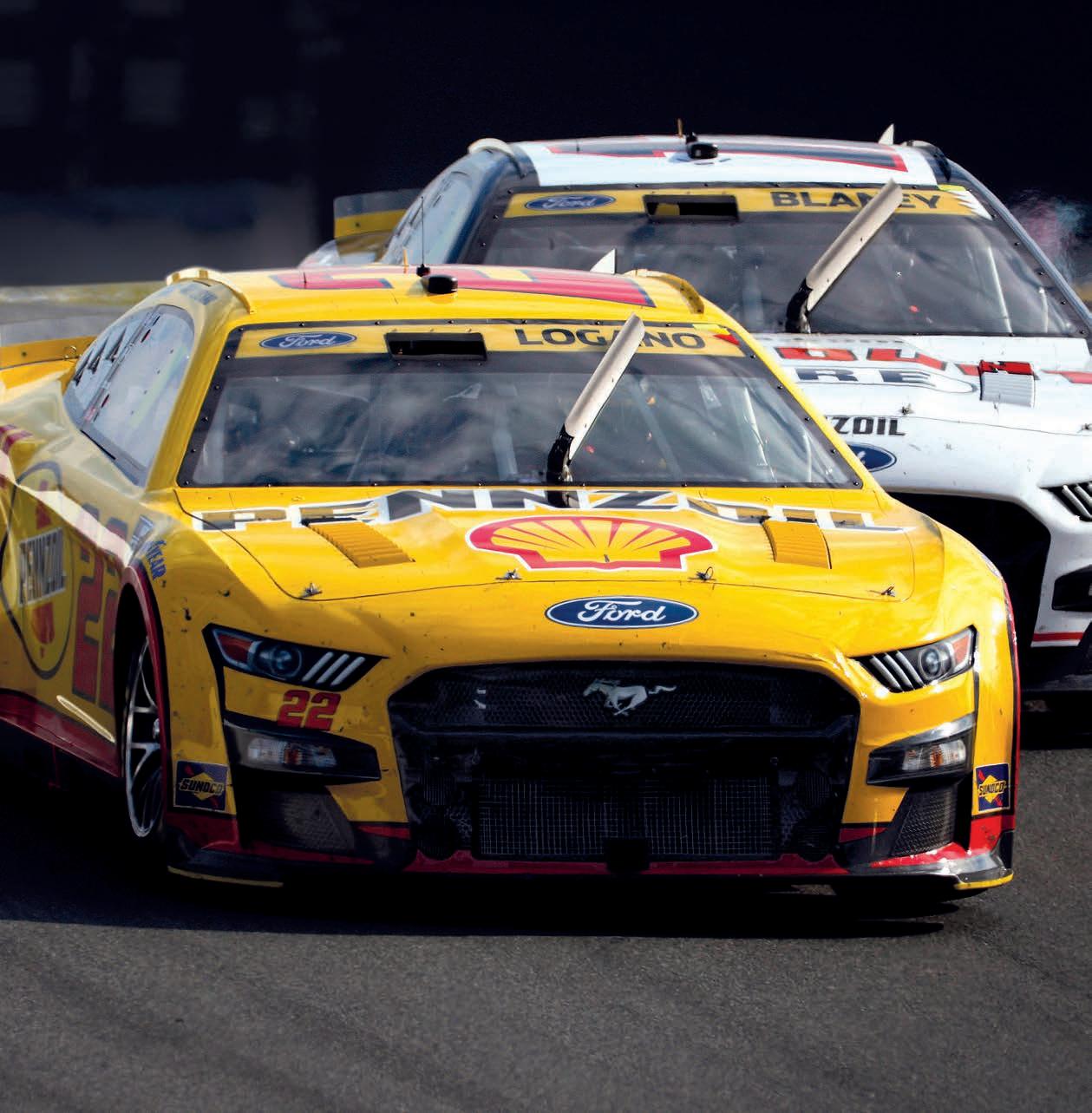
The introduction of NASCAR’s Next Gen racecar has been hailed a success, but its early development was a hot and bumpy road
By DR ERIC JACUZZI AND CHRIS POPIELANASCAR’s Next Gen vehicle has been an incredible success on track, with an unprecedented 17 different winners and numerous thrilling races over the 2022 season. While a great year was certainly hoped for, such an outcome was far from certain in mid-to-late 2021 as teams began testing their own cars.
As could be reasonably expected with the debut of a brand new car, issues began to appear that were not seen during NASCAR’s own prototype testing. This is the story of

the race to fix some of the most concerning issues before the new car hit the track, with high hopes of delivering one of the best seasons in NASCAR’s recent memory.
NASCAR’s on-track testing approach with the Next Gen car extended through much of the early part of 2021, beginning with a two-day test at Richmond in March. The new vehicle, dubbed Prototype 1 (P1), was the initial platform designed to evaluate
all the new systems on the car. But, by the time of the test, most of P1 was already obsolete as the design was rapidly evolving, so it was decided to advance the design and build a new vehicle, Prototype 3 (P3), which skipped over an anticipated evolution of P1. This car was run initially at Texas in May and then for the remainder of the NASCAR testing schedule until team testing began.
Cut to September 2021, where eight teams participated in the inaugural organisation test of the Next Gen at Daytona.
By the time of the [first] test, most of [Prototype] 1 was already obsolete as the design was rapidly evolving, so it was decided to advance the design and build a new vehicle, (P3), which skipped over an anticipated evolution of P1


In the humid Florida heat, high cockpit temperatures were a universal complaint from the drivers. With its heat, humidity and full throttle lap, Daytona represents a tremendous challenge to keep the cockpit cool at the best of times, but the situation appeared worse.
Aside from the heat, drivers expressed some concern that the car seemed to be erratic with changes in ride height. This was due to attendant aerodynamic balance changes, as well as the car impacting the damper travel limiters that had been implemented to limit ride height.
Leaving the test, the NASCAR R&D team knew time was running out to make the required changes before the 2022 season, and immediately started addressing these issues.
During the first day of testing at Daytona, ambient temperatures recorded inside the cockpit were significantly higher than those drivers were accustomed to with the Gen 6 car. Indeed, some areas of the cockpit were too hot to touch at times during a test run. These areas included the pedal box, shifter and even the rollcage bars at times.
On the exterior, drivers were noticing intense heat when sticking their hand out the left side window net (a usual approach to cool themselves when coming in from a run), as well as heat coming out of their helmet air conditioning units.
This was a cause for alarm as most of the runs that day were under 30 laps and ambient temperatures were not at the upper reaches of those expected in an average season.
NASCAR and the participating teams huddled up afterwards to discuss different ways to eliminate heat from the vehicle. One of the main focusses was the long exhaust pipes that travelled along the sides of the vehicle and underneath the driver. Different approaches were taken to reduce heat here, including cutting out portions of the floor underneath the exhaust pipes. Unfortunately, not much testing was performed as rain spoiled much of the second day of the test.
With no drastic changes in the cockpit when comparing a Gen 6 vehicle to the Next Gen, NASCAR was convinced any contributing factors to increased temperatures were coming from outside the cockpit.
To determine what was contributing to the heat issues, NASCAR constructed a thermal model of the car designed to simulate the various heat sources from the engine and powertrain. This is shown in figure 2. A glaring issue was the propagation of both exhaust gases and expelled transaxle heat via the driveshaft tunnel. This phenomenon was due to the existence of a low-pressure zone in the under-bonnet region since the front wheel wells and engine bay are not enclosed, as they are in a traditional sportscar.


This was done to make working on the car more compatible with the processes NASCAR crews were used to with the Gen 6, but the low-pressure gradient it created from the front to the rear of the car resulted in heated air being drawn forward through the driveshaft tunnel.

A two-pronged approach mitigated this effect: adding a central NACA duct through the floor into the driveshaft tunnel and creating exits at the rear of the car to draw out heated air. The floor duct helps push warm air down the driveshaft tunnel and out through the exits at the rear. These modifications resulted in a small loss of total downforce and roughly four per cent forward balance shift.
Another issue was the length of the exhaust pipes down the side of the vehicle. With long pipes, the exhaust plumes were being drawn into the rear wheel wells and, again, forward through the driveshaft tunnel. A switch to


a shorter exhaust pipe and an earlier exit helped dissipate much of the heat going underneath the cockpit and conducting into the chassis. Although the short pipes showed gases being ingested into the rear of the car, it was much less than the long pipes in terms of heating, due to their mixing with outside air before ingestion. Figure 3 graphically shows the difference between the long and short exhaust plumes.
Figure 4 shows the design detail of the long and short exhaust pipes, as well as the triangular cut outs in the bottom of the sills / rocker boxes added to help introduce air around the short pipes.


However, even with these changes cockpit temperature investigations using FLIR cameras and thermocouples showed that not only were cockpit temperatures increasing, but they were also stagnant, with no signs of heat evacuation.
Traditional ways of cooling the cockpit, such as the mandated double NACA duct on
the right-side window opening and open leftside quarter window NACA were ineffective.
After further investigation, it transpired hot air exiting from the radiator / oil cooler through the bonnet vents was being ingested on both sides of the cockpit. This hot air was found to be attached to the vehicle from the a-posts, all the way down both sides, for all three manufacturers.
This was not observed during NASCAR’s own prototype testing, as a generic body and louvre design was used, with the latter located more inboard and further forward.
Due to these findings, a fully sealed rightside window was mandated at all tracks, and the mandated open left-side quarter window NACA duct was removed. Another change made was the removal of the left side a-post window net. This was initially installed for safety purposes to protect the driver from debris entering the cockpit and was used throughout NASCAR’s Gen 6 era. Instead, this area was closed off with a permanently installed triangular polycarbonate window known as the a-post deflector, shown in figure 5. This simple piece lowered the temperature around the driver by roughly 10-15degF by reducing the amount of hot air ingestion from around the a-posts.
Issues still existed on how to effectively introduce ambient temperature air into the cockpit though. After numerous iterations on different areas of the vehicle, NASCAR settled on a driver cooling duct located on the upper
After further investigation, it transpired hot air exiting from the radiator / oil cooler through the bonnet vents was being ingested on both sides of the cockpit
right side of the front windscreen and slots in the back glass, as shown in figure 6. The driver cooling duct has two circular openings, one to introduce air directly into the cockpit and the other with a hose attachment that leads to the driver’s foot box area. This significantly increased airflow into the cockpit and, at the same time, cooled the pedal box.
During competition, the driver cooling duct must not be obstructed. Nor the rear window slots, which also introduce airflow into the cockpit, apparent in figure 7


Aerodynamically, the driver cooling duct added a small amount of drag on the vehicle while the rear window slots caused the vehicle to gain a large amount of rear downforce and drag. Other areas that were investigated to help airflow into the cockpit, including the top of the greenhouse, had a significantly negative aerodynamic impact.
The valuable lessons NASCAR learned from the cockpit heat reduction programme will eventually make their way into other series in NASCAR.
The decision to use a full aerodynamic floor was a first for NASCAR, and was developed over a year and half, with thousands of CFD runs and approximately 100 hours of testing at Windshear, Inc. One aspect of its performance that is misleading from CFD is its precise behaviour in traffic.


When performing CFD simulations of one vehicle following another, the two vehicles are set at a particular ride height and the flow field is computed. It is then possible to draw conclusions on the expected deficit a trailing car would experience. What this approach does not account for, however, is the effect the reduced aero load has on the suspension and, consequently, the ride height of the vehicle.
Like all ground-effect vehicles, the Next Gen car craves a certain proximity to the track surface that is set by teams in single car running. The downforce of the car pulls the car down to a height that is calculated to result from the effect of spring compression or ride height limiters. NASCAR teams previously employed rigid polyurethane or rubber bump stops that controlled the precise body ride height under load, but these were outlawed with the Next Gen. As a result, the ultimate stop for damper travel became a small, harsh stop on the damper shaft, making damper springs the aerodynamic platform control.
This is not a problem in single car running but, when in traffic, the reduced energy airflow not only reduces the downforce on the trailing car, but also increases its ride height due to the decrease in loading. This further reduces downforce, with most of the loss occurring on the front of the car.
It was unclear how dramatic this effect would be under race conditions, but it proved to be pronounced when felt by the drivers in traffic. In studying the aerodynamic qualities of the car as it moved through heave and pitch, it was obvious that the rear of the car behaved in a largely similar performance envelope. The front, however, built downforce up to about an inch from the ground but then it began to stall. This led to larger aerodynamic balance changes as the rear of the car made constant downforce, while the front increased with proximity to the ground.
When in traffic, the reduced energy airflow not only reduces the downforce on the trailing car, but also increases its ride height due to the decrease in loading
cutting-edge wind tunnel technology.Add a 180 mph rolling road.
build in the best in precision data acquisition capabilities.When we created the world’s first and finest commercially available full-scale testing environment of its kind, we did much more than create a new wind tunnel.
cutting-edge wind tunnel technology. Add a 180 mph rolling road.

build in the best in precision data acquisition capabilities. When we created the world’s first and finest commercially available full-scale testing environment of its kind, we did much more than create a new wind tunnel.
created a new standard in aerodynamics.
created a new standard in aerodynamics.
Now, some of this could have been dealt with using aerodynamic practices more akin to a GT car, however, the ‘stock’ car appearance remains an important consideration for NASCAR, along with a general reluctance to add any pieces that could become track debris.
In-depth review of the splitter behaviour in heave from both CFD and experimental results showed a gradual increase in pressure coefficient on the lower section due to ground effect. This led to investigating whether disrupting the flow in this area would yield the desired results in CFD.
Ultimately, the addition of the splitter stuffers, shown in figure 8, nearly flattened the lift coefficient vs ride height for the car, which was immediately noticeable to drivers on track. To regain some of the lost downforce, centrally-mounted strakes were added forward of the floor centre (figure 9) and the diffuser outer tunnel walls extended downward with ¾in carbon skirts (figure 10).
An interesting by product of this change was that rather than maximum downforce occurring with the nose of the car near the ground, it occurs with the nose up and the rear squatting. This arrangement allows the maximum air volume to reach the diffuser, creating peak downforce for the car.
A further challenge that appeared early on during the season was that the OEMdesigned cooling systems did not have adequate airflow at shorter tracks and road courses. Because the manufacturers build the engines and have years of data on operating them, there was no NASCAR requirement on airflow through radiators. This flow is measured behind the radiator core by anemometers and reported as velocity ratio (VR), which is the air speed through the radiator divided by the ambient air speed.
This issue first appeared at the Clash at the LA Coliseum, which was a 0.25-mile event for which the cars were not designed, as it was announced after the Next Gen was being built. Saturday’s initial practice saw vehicles running on track for just a few minutes,
returning to the pits outside the stadium and then driving back to the entrance of the tunnel to wait to enter again. This led to steadily climbing engine temperatures due to low airflow and heat soak.
For race day, NASCAR agreed to allow the manufacturers, if they chose, to remove some, or all, of their radiator exit louvres on the bonnet to coax more air from the radiator. That appeared to work as there were no heatrelated issues during the race.


But concern began to rise beyond the early oval events that road courses may also pose a problem. Teams struggled early on with deciding how much protection from debris was required for the new car, which resulted in some cars overheating at Fontana.
Teams quickly realised that the upcoming Circuit of the Americas race would pose a legitimate concern for temperatures, without debris even factoring in. As a result, NASCAR and the manufacturers agreed to implement the option to declare an extreme cooling package specific to each make that could be fitted prior to the race weekend. Mirroring the Clash, this often involved removing obstructions in the duct exit, or increasing overall exit size in the case of the Toyota.
For the 2023 season, NASCAR implemented a minimum VR requirement for the vehicles of 0.1, meaning that with no obstruction behind the radiator or removal of louvres the cooling system must meet this requirement. In some cases, this represents a nearly 50 per cent increase in VR compared to the 2022 designs. This increased capacity is mainly achieved
through larger and more efficient exits through the bonnet for the radiator flow.
It was also agreed between NASCAR and the manufacturers that there will be no concession for modifying cooling systems next season. The only option is to pit the car and cool the engine if required. It is anticipated that the new regulations will address this issue for the 2023 season.
The Next Gen car continues to evolve as it accumulates race mileage under its belt. Continuous improvement of component durability and cost is a daily occurrence, but frantic re-development will hopefully now be just a memory. NASCAR’s 2023 Garage 56 entry will now be the next major event on the horizon for R&D, along with a battery electric vehicle concept to represent a possible demonstration series in the 2024 season.
Though the hectic months prior to the launch of the Next Gen car will not be missed by the team at R&D, lessons learned in preparing the car for racing will live on. We are now looking forward to showing NASCAR to the world in France in 2023, and will be excited to share the development of our Garage 56 entry at a future date.
For the 2023 season, NASCAR implemented a minimum VR requirement for the vehicles of 0.1Fig 8: So-called splitter stuffers helped flatten the lift coefficient vs ride height for the car Fig 9: Engine panel strakes helped regain lost downforce. Note central tunnel NACA duct visible Fig 10: Extended carbon skirts on the outer walls of the diffuser tunnel also re-captured some of the lost downforce







Mercedes AMG has had a rude awakening in Formula 1 in 2022. Racecar talks to Mike Elliott, the team’s technical director, to nd out how it has approached the problems


 By STEWART MITCHELL

‘It’s easy to say we’re having a tough time when we’ve been through the last eight Formula 1 world championships, winning them all, and we’re not in that position this year,’ says Mike Elliott, technical director of Mercedes AMG Formula 1, on the team’s 2022 performance to date.


‘We’re bound to think it’s not brilliant. However, looking at a wider context, the 2022 regulations intended to mix up the field and improve the show. In that way, Formula 1 achieved those outcomes.’


At time of writing, with four races left of the season, Mercedes was sitting third in the Constructors’ Championship, 67 points behind Ferrari and an insurmountable 232 points behind Red Bull Racing.
Unlike the previous generation of dominant Mercedes machinery, the W13 has had a somewhat bumpy coming of age

Mercedes’ change of fortune since the introduction of the new era has been well documented. Its car this season, the AMG F1 W13 E Performance (the 13 referring to it being the 13th car produced by the Mercedes-AMG works team since re-entering F1 in 2010), is the product of a top to bottom re-design in line with this year’s Formula 1 regulations. The only carry-over element from its predecessor is the steering wheel.
Operating from a blank slate, with a steep development curve, the team’s Brackley and Brixworth engineering squads have had to push even harder than the previous generation of Formula 1, where they stole a march on the competition and carried it through to the end of the era. Unlike the prior dominance of Mercedes machinery, though, the W13 has had a bumpy coming of age.

For context, the 2022 rules have reduced the cars’ wake (turbulence caused by the car passing through the air) as a function of the new aerodynamic regime, allowing competitors to get closer to one another, particularly in the corners. The challenge of overtaking in the previous generation of F1 was primarily down to this wake. However, the lower wake means the corner gains are somewhat outweighed by the tow effect (slipstreaming) reduction on the straights.
Net, Elliott feels the cars’ resulting closeness and overall competitiveness over an individual lap have not changed much.
‘In terms of closing up the grid, it’s probably the same split as we’ve had before,’ he notes. ‘I guess we are the only ones that have seriously changed position this year, and that’s our problem to deal with. We’ve ended up with a poorly behaving car and an uncomfortable ride for the drivers, thanks
to the direction we’ve taken with the new aerodynamic establishment.’
Thanks to the introduction of groundeffect aerodynamics, the 2022 rules reward running the car as close to the ground as possible. But if platform control isn’t sufficient, this low running can induce instability in underfloor flow fields and lead to so-called porpoising and bouncing. Mercedes suffered badly from flow field instability in various ways throughout the 2022 season, but has not been alone in this battle.
‘I don’t think any teams effectively spotted porpoising over the winter period between 2021 and 2022,’ says Elliott. ‘We did anticipate having to run the car very low under these full ground-effect regulations. However, the challenges of ground-effect aerodynamics are stronger on some cars than others. They are unique to the flow field structure under the car, its set-up scope and performance window.’
Cars have three modes in their suspension: roll, pitch and heave, which operate at different frequencies. In a porpoising scenario, the car ends up with a phase shift between its front and rear aerodynamics, which feeds into the pitch mode. With these cars, teams see predominantly heave, and some pitch, which depends on speed and the characteristics of the circuit.
‘It became apparent early, even without significant aerodynamic work, that these cars wanted to run very low to the ground. So we focused on designing the floor to survive in those conditions, and at the ride height that would be most performant,’ says Elliott. ‘We underestimated one problem and didn’t spot another, which is why we have the behavioural issues. One thing we can put our finger on is that it is a consequence of the aerodynamic changes in the regulations.’
Mercedes claimed to make good progress ironing out its issues regarding underfloor flow field instability that led to the porpoising phenomenon seen so dramatically in the season’s early stages. However, the W13 still suffers from ‘bouncing’ – a heave motion response caused by the underfloor aerodynamic instability.
‘Bouncing issues are complex,’ notes Elliott. ‘The aerodynamics put energy in the vertical motion of the car due to a phase shift between the aerodynamic load and the car’s ride height position that gives a net energy input more than the dampers can deal with.
‘The fact we have to run these cars so low to the ground, with so much downforce on them to be performant, means they must run really stiff, and that’s a huge contributor to these significant consequences.’
As well as the changes to the aerodynamic regulations, the new-for-2022 18in wheel and tyre package has changed how teams approach car performance.
‘The challenges of groundeffect aerodynamics are stronger on some cars than others. They are unique to the flow field structure under the car, its set-up scope and performance window’
Mike Elliott, technical director at Mercedes AMG Formula 1
‘As per every era of Formula 1, there are significant amounts of lap time to be found by improving the car’s dynamic behaviour, and engineers can find some of this in setting up the car to get the tyres into their performance window,’ notes Elliott. ‘The new tyres want slightly different things to get them into the window that works when

compared to the previous 13in ones. Though this isn’t the way to solve the challenges we’ve been facing with car behaviour.
‘You have to put it in perspective. The tyre is not particularly stiff, and then you’ve got stiff suspension springs and, in parallel with the suspension springs, you have the stiff dampers. In reality, these cars are inflexible, so it’s hard to dampen the motions and take a lot of energy out of the car’s movement.’
The chassis regulations also changed for 2022 and now include a more challenging side squeeze test, requiring a higher strength than the previous generation of cars. The aerodynamic regime has also driven teams to stiffen their cars in areas they otherwise wouldn’t have in the last regulation set.
Even with good engineering design, these elements add significant weight to the cars, which have gone up from 752kg to 798kg.
Teams throughout the grid have not pushed to meet the minimum weight, instead choosing to maximise more lap time performant opportunities that were perceived as more rewarding than just having the lightest car possible by regulation.
‘We were overweight at the beginning of the season, though we have done a lot of work to bring it down towards the minimum,’ explains Elliot. ‘However, weight is an interesting equation in this era of Formula 1. Although it’s one of the key performance drivers, it is also limited by regulations. Because of that, car development differs from what one might think.
‘We are always targeting a lower lap time, and reducing the weight to the minimum amount gains a certain amount of lap time performance, but we’ve found that a heavier car with a more sophisticated aerodynamic package actually generates much more performance on the track.
‘Because we have so many tools to develop a more performant car, lowering the weight to the minimum isn’t as dramatic a driver as it once was in Formula 1.
Additionally, we’ll take a weight penalty for a more reliable car, as a DNF or grid penalty from replacing components that have failed, or run over the maximum unit allocation for the season, carries a high burden in the championship standings.’
The position of the homologated side impact structure is defined in the regulations, but early in the design phase for the W13, Mercedes spotted an opportunity to design a wing around the upper side impact structure to add downwashing flow in that area.

‘We spent a lot of the winter figuring out how best to work this loophole, and wondering if there was any part of the wording that would see the other teams trying to get it stopped,’ says Elliott of the wings that sit either side of the driver’s cell. ‘We went for it at a certain point in the development, and it performs well and suits our overall aero regime for the car.’
Others are yet to follow suit, instead using the space Mercedes carved away for this structure to house components.
The teams’ aerodynamic philosophies dictate the direction they go in terms of the weight of each component that affects aerodynamic performance. Once a philosophy is settled on, much of the design concept then comes from that, and forces you down a particular route to effectively deploy it. Interestingly, there is a variety of concepts seen across the 2022 grid. Mercedes has gone with a very narrow packaging concept, while much of
‘In reality, these cars are inflexible, so it’s hard to dampen the motions and take a lot of energy out of the car’s movement’
the rest of the grid has chosen a wider body to suit their philosophies. Elliott doesn’t think there’s a big difference in the potential of any one philosophy because the detail is where it counts, much of which is under the floor.
‘When you look at a Formula 1 car as an aerodynamicist, you immediately see that the dominant features are the front wheels. These generate a tremendous amount of wake, and how you deal with that is the key to performance. In the past, we would counter the effect of front tyre wake by implementing complex structures behind the wheels in the form of bargeboards and other wake control devices. But in 2022, we can’t do that. So, our philosophy for the W13 was to bring the bodywork in the central chassis of the car as tight as possible to the driver cell and the PU to have a minimal effect from front tyre wake.’
The W13’s aggressive sidepod packaging is partly thanks to the compact design of the M13 power unit, which features volume dense systems such as water-to-air intercooling. On its creation, Elliott says the team have built up a lot of power unit systems modelling capability over the last few years, enabling them to do a superior job at predicting where the heat capacity and flow rates need to be in order to be as efficient as possible.
‘We do a lot of work to optimise airflow through the car and work out the pressure losses around radiators,’ he says. ‘Charge air cooling is based on water-to-air heat exchange because we see a massive benefit in that in terms of the entire design philosophy of the car. Its role cannot be underestimated.’
The underfloor aerodynamic regime only slightly changes the packaging of the cars. However, Elliott notes that, in every era, Formula 1 teams always try to push the limits when it comes to packaging


‘One significant change for us was the limited wheelbase regulations this season.

‘Our philosophy for the W13 was to bring the bodywork in the central chassis of the car as tight as possible to the driver cell and the power unit to have a minimal effect from front tyre wake’Mercedes’ charge air cooling is based on water-to-air heat exchange and coincides with the design philosophy of the car. This allows the car to run fewer cooling louvres in the body than many of its competitors The W13 floor has an exit flow condition positioned midway down. This rejects airflow under the car that isn’t in the tunnel flow. Slots further back on the floor edge re-ingest some of the exit flow to work the diffuser and control rear tyre jets Unlike the rest of the grid, Mercedes has chosen to go with a very narrow packaging concept for this car, wrapping the bodywork extremely tightly around the driver cell and power unit


We had the longest car in the previous regime, giving us some freedom. We certainly had a lot more packaging work to do in 2022.
‘The cost cap also drives this because you don’t want to reinvent every bit of the car every year. So, much of our thinking over the winter was about how we could develop a car where much of the architecture and critical systems could carry over from year to year. That drove more work on packaging than the aerodynamic regime.’
‘We’ve come through the 2022 season so far with a huge amount of humility,’ says Elliott of the learning journey into this new era to date. ‘We have looked at all the other car solutions on the grid, investigated how other teams have arrived at their solutions and wondered if any of them are better than ours. It’ll be interesting to see how the cars turn out next year with all the lessons of the first season of this regulation set behind us.
‘The most significant thing we have learnt in 2022 is how to go about adapting to a new rule regime, and figuring out how best to find a performant compromise in adverse circumstances. We’ve learnt how to find the right operations approach to finding performance in a very different type of Formula 1. Without giving too much away about what we did wrong in the first place, we’ve learnt and adapted to this new F1.’
Earlier this year, the World Motor Sport Council confirmed there would be alterations
to the 2023 technical regulations, citing driver safety as the main reason for the adjustments. These changes include raising the floor edges by 15mm and raising the diffuser throat height. The diffuser edge’s stiffness will also increase, and there will be a mandated sensor to monitor porpoising more effectively.
As to how the rule changes for 2023 will affect Mercedes’ performance, Elliott says, ‘the raised floor edges are probably the main thing that will affect the car aerodynamically, and this will influence performance. I think that’s going to keep the floor edges off the ground in the high-speed sections, and I think that, generally, it will be helpful for most teams running the car really low.

‘On the flip side, to recover the lost performance from that, we’ll have to see which way drives us, whether to run the car lower or see a re-design. Running the car lower could end up back in the same order with the same problem, but we will investigate that. 15mm is not a huge move.
‘We’re still going to have ground-effect cars, and they’re still prone to underfloor flow field instability. If you’re not careful with how you deal with that aerodynamically, you’ll still have the same problems.’
The 2023 car, Elliott admits, will see a different design to the current W13, succeeding Mercedes’ investigations into the aerodynamic concepts of the other teams lined up on the grid.
‘Normally, in a set of rule changes, as the rules get fixed – and they’re fixed for
longer and longer these days – the teams tend to converge. I think the intention of the new rules and the cost cap was to try and constrain the grid, though the front three teams are as far ahead as they have ever been. Whether that will change in time, we will just have to wait and see.
‘If you look at Ferrari, Red Bull and Mercedes, the three quickest teams, they all look very different. The logical thing is to copy the quickest one, which, unfortunately, is Red Bull. But you can’t just photocopy a car and suddenly jump to the front of the grid. It doesn’t work like that. It’s more about trying to understand what people are thinking and their approach, which will converge a bit and maybe the teams will move together, but I don’t think it’ll be next year we see parity. I think it will take a few years.’
‘The most significant thing we have learnt in 2022 is how to go about adapting to a new rule regime, and figuring out how best to find a performant compromise in adverse circumstances’


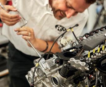


The Haas F1 Team is a truly global operation, with its HQ in North Carolina, the Design Office in Maranello, staff based at Dallara’s facility in Varano de Melegari, Italy and in Banbury, UK. Head count is currently around 350, but the team is looking to increase that to 400 for 2023

You have to hand it to Gene Haas and Guenther Steiner. Between them, they played Formula 1’s constructor regulations to perfection, so much so that without an in-house design office, or a fully-equipped factory, they have mounted a credible world championship campaign and, at the close of the European grand prix season, Haas lay seventh, ahead of Aston Martin, AlphaTauri and Williams – all teams with comprehensive facilities at their disposal.
Expressed differently, Haas F1 Team was about the only entrant able to file its budget cap reports on time, as required by the FIA’s financial regulations, without fear of breaching 2021’s $145m limit.
The history of the team, which took its first start in the 2016 Australian Grand Prix (finishing sixth, before going one better next time out in Bahrain) harks back to Steiner’s 2001-’03 tenure as Jaguar Racing’s technical director, but in real terms it was the aborted 2009 USF1 project that sparked Haas F1.
‘It would not be fair to say I learned what not to do from those teams,’ Steiner, who harks from Italy’s South Tyrol Germanspeaking area, told this author with a smile in 2015, ‘but there were lessons to take aboard.’

Between those two time points, he established Red Bull’s NASCAR operation and founded a carbon fibre business in Charlotte, USA – home to North America’s heavy metal series – where he came into machine tool magnate, Gene Haas’, orbit. The two had been approached for assistance by USF1, Steiner on composites, Haas supplying machine tools, and kept in contact after the project’s (predictable) demise.
At Jaguar, Steiner, who joined from a similar role at parent company Ford’s rally team, scoured F1’s technical and sporting regulations, particularly the Concorde Agreement, learning what to do and, perhaps more crucially, what not to do.
They say the most important thing in any category of motorsport is to read the rules. But few can claim to have read the rules quite as cleverly as those behind Haas F1 Team
Provided a team holds the intellectual property rights to ‘listed parts’, as per Concorde, they are deemed a constructor, regardless of who designed or produced the components
As a naturalised American, his ambition to be team boss of a US Formula 1 outfit burned deep, so he approached Ferrari about running a third car for an American driver.

The concept was embraced by the Scuderia, but rejected by the FIA. So, he investigated a Ferrari customer operation instead. Again, thumbed down by the governing body (and the other teams), so instead he turned to F1’s technical regulations, quickly learning that F1 constructors need not be constructors.
Explanation: provided a team holds the intellectual property rights to ‘listed parts’, as per the Concorde agreement, they are deemed a constructor, regardless of who designed or produced the components. Back then, listed parts were effectively ‘wetted parts’ ie those that got rained on, so front / rear wings, outer profile and body parts, crash / rollover structures and floor / diffuser.
All the rest could be bought in, so Steiner called then Fiat / Ferrari boss, Luca di Montezemolo. The two already knew each other from Italian rallying via Steiner’s stint with the privateer Jolly Club team, and then later from third / customer car proposals.
‘Would Ferrari be prepared to supply unlisted parts?’ he asked the Roman nobleman, who replied in the affirmative,
provided Steiner provide the relevant guarantees. Crucially, this meant Steiner had access to Ferrari powertrains, as long as someone paid for them.
Next stop was Dallara, to enquire whether the world’s largest customer car constructor would design and build all non-listed parts
required to fit the Ferrari Meccano set, and be prepared to cede IP rights to Steiner’s project on the basis that these were bespoke parts for specific use. Same reply: ‘If costs are covered, sure, why not…’
Enter Haas, then seeking to expand his eponymous machine tool business

beyond the USA and into auto manufacturing regions such as Brazil, China, Malaysia and Mexico – all countries on the F1 calendar, or about to join. If Steiner obtained FIA approval for the ‘constructor-without-constructing’ concept, he agreed to fund it. The FIA, seeking to fill F1 grids, agreed.


This was in 2014 / ’15 and, by 2016, the US-entered team was on the grid for its first season and shading Sauber and Renault with eighth place. That championship result was repeated the following year before improving to fifth in 2018. Not bad for a team whose ‘factory’ consists of a one metre square filing cabinet containing Ferrari, Dallara and F1 contracts, and whose wind tunnel is situated in Maranello.
Add in that Haas’ Kannapolis complex, situated beside the Stewart-Haas NASCAR outfit, acts as global headquarters for the F1 operation and fabricates tooling, jig and fixtures for the team, and a case could be made that Haas’ F1 entrant’s licence should be issued by the United Nations, what with staff based in the UK (race operations), Italy (Ferrari and Dallara) and USA. Around 30 nationalities in total are represented.
By now, there were rumblings of imminent budget caps. Liberty Media had acquired F1’s commercial rights in early 2017, and sought

ways of paying teams less as it follows that the less they spend, the less their imperative for billion dollar prize funds. If the ‘new era’ cars were to be cheaper to design, build and race, an inherent part of the 2021-on regulations was a revamp of parts categories (see sidebar).
Crucially, though, the cap meant swingeing head count cuts for major teams. Where the Big Three numbered over 1000 in their performance departments, the right size was projected at 650. Mercedes consequently diversified into applied sciences with yachting and cycling projects, and ramped up in-house work for parent company, Daimler. Red Bull, meanwhile, embarked on the Aston Martin Valkyrie and its RB17 Hypercar, plus shifted staff to sister team, AlphaTauri.
By contrast, Ferrari opened a ‘customer technical services division’ to offer contract engineering services to Haas – therefore replacing Dallara, then ramping up on road car projects anyway – subject to FIA approval. The governing body considered the facts and insisted upon separate premises and systems in order to prevent ‘coffee-time chats’, during which secrets may be whispered, plus the right to make unannounced spot checks, which it has duly done.
Which brings us neatly to the first visit by a publication to the (contracted) Haas Design Office, situated within Ferrari’s Gestione Sportiva complex at the end of Via Ascari, overlooking Fiorano circuit. Haas’ offices are self-contained, with access by coded card

only and, significantly, our invitation was extended by Haas, not Ferrari.

How complex was it to set up what is effectively a team within another team’s building, while conforming to FIA’s requirements, particularly when competitor teams keep politicking about Haas’ structure? After all, engineering staff are effectively now Haas employees, albeit paid by Ferrari to maintain company benefits and perks, and work out of the same building as previously. Time spent is now ‘booked’ to Haas.
‘It wasn’t too difficult, because in 2020 / ’21 we came down [in technical head count due to Covid],’ admits Steiner in his trademark accented staccato style, ‘and it helped that the people were mainly working for Dallara, so it was pretty easy [for us] to reduce [numbers].
‘We were also helped by circumstances, because the budget cap came in and Ferrari had people available. I spoke to Mattia [Binotto, Ferrari team principal] and told him I need to ramp up.
‘He said, “Maybe we can work together on some of the people [who] we need to move to other departments. Tell me what you need.”
Whereuntil the end of 2021, F1’s components were categorised on a binary basis, either listed (own IP) or unlisted (free sourcing), under the ‘new era’ regulations there are now four umbrella groups, making Haas’ operation simultaneously easier and more complex, depending upon the specific component.
The four current categories and some examples of each are outlined below.
• Listed Team Components (LTC) are those whose design, manufacture and IP is owned and / or controlled by a single team or its agents on an exclusive basis. Examples are survival cell and primary roll structures, front impact structures and the fuel bladder.
These items must be unique, and Haas must hold the IP rights to them, whether designed and / or supplied by Ferrari’s ‘customer division’, Dallara or any other entity. Around 10 per cent of parts groups within categories are LTC, but many are major items.
• Standard Supply Components (SSC) are those whose design and manufacture is carried out by a supplier appointed by the FIA, to be supplied on an identical technical and commercial basis to each competitor team. Effectively, these items are mandated, and teams have no choice but to source them from the official supplier. Examples are (BBS) wheel rims, tyre pressure and clutch torque sensors, (Pirelli) tyres, primer pumps, flexible pipes / hoses and fuel flow sensors.
These are items required for FIA monitoring or mandated for costs reasons. Around 20 per cent of parts groups within categories are SSC.
• Transferable Components (TRC) are components whose design, manufacture and IP rests with a team or supplier but can be freely supplied to another team without limitation. Haas may avail itself of all these parts provided their notional value (see Financial regulations box out on p??) is equal to, or better, than it could produce or outsource such parts for itself. Examples are gearbox carrier and cassette, rear impact structure (fits gearbox), full front / rear suspension assemblies and non-LTC and SSC fuel system items. Around 30 per cent of parts groups within categories are TRC.
• Open Source Components (OSC) are components whose design specification and IP is available to all teams through the mechanisms defined in the regulations. Examples are pedal assemblies, wheel retention systems, brake systems, master cylinders and fuel system hydraulics. Around 40 per cent of parts groups within categories are OSC but these are standardised, non-performance items.
Whilst Haas F1 now has a greater choice of sources, it still has to evaluate all open components to ensure it obtains the best prices, crucial under a budget cap.




So, when I say it wasn’t too difficult, and didn’t give me sleepless nights, it’s because we found a good solution.
‘Simone [Resta, formerly Ferrari’s chief designer, now Haas technical director] was drafted in in December 2020 to set it up. The first question was where do we put the offices? So we started looking around Maranello, and then there were offices planned by Ferrari for expansions that they no longer needed [due to budget caps].’
Resta, like most of Haas’ Maranello staff, is on Ferrari’s payroll and acts as our guide for the day, explaining that around 100 staff operate from here, with the figure varying according to workload. It roughly works out at 30 in the Design Office and 70 aero staff working from offices situated alongside Ferrari’s wind tunnel.
‘Basically, what we have here in Maranello is a group of designers, aerodynamicists, test engineers, structural engineers, all the development group, plus some people involved with simulations,’ he says, adding, ‘while the model makers, they’re coming in mostly from Dallara.

‘There’s a nice group of people based at [Dallara’s base in] Varano de Melegari, say
50-70, and then there are more people at the operational base in Banbury, say 120 or 130.’
Add in folk in the USA and the number quickly spirals over 350, with additional hands required during pre-season car build. Indeed, the team is planning for 400 heads for next year and foresees 500 in the medium term. A new title sponsor was added in October, MoneyGram, which will enable them to increase spend in non-regulated areas.
‘We are now within five or 10 million [dollars] of the budget cap,’ smiled Steiner ahead of the announcement.
How does Resta decide which parts to design and build? The main hardware is easy. The complete ‘rear end’ consists of Ferrari’s latest specification power unit, gearbox and electronics / hydraulics, the latter plugging into the team’s own systems. Taking the rear suspension and crash structures is a nobrainer given they bolt onto the gearbox. For the rest, the design team picks and chooses from what is legally available.
‘Normally, we try to maximise in the way our business model has been defined. We try to maximise our opportunities wherever possible, showing what we can take where. There is always a chance you can carry over components. It’s a group effort but, ultimately, I’m accountable for things.’
He has a counterpart in Ferrari he meets regularly, and between them they decide the ‘menu’, within established processes.
‘There’s a process that involves regular discussion,’ confirms Resta. ‘It is all documented, with details where they can exchange in advance the areas where we are able to buy. Then they exchange [computer] models so we can keep up to date.’
‘Basically, what we have here in Maranello is a group of designers, aerodynamicists, test engineers, structural engineers, all the development group, plus some people involved with simulations’
Simone Resta, technical director at Haas F1Much of the main hardware for the F1 cars comes from Ferrari, other parts are mandated by the FIA and the rest are sourced from whichever supplier is deemed the most operationally efficient


Resta admits that being a customer is not ideal, due to potentially being a step behind, but says, ‘You try your best to follow what’s going on, within limits. In the end, there’s not much room for frustration, you just get on with it, do the best you can and try to maximise your [return on investment].’
Once designed, build of parts is handed over to sub-contractors – mainly Dallara, but whoever offers a good deal within quality, quantity and delivery parameters. Dallara also steps in with engineering services during peak periods, as and when required.
‘Dallara is like an expansion tank for us during [new car] engineering time in November, December and January,’ explains Steiner. ‘They also manufacture all the structural parts, so those you need to do an FIA test, things like that. Ferrari only make those parts we buy direct, [as] they don’t have capacity for us [for other parts]. The rest is from anywhere, but only from good suppliers.’

Dallara then builds the cars, in conjunction with the Haas race crew.
‘Assembly of the car is normally at Dallara in January, because everything is there and, if something is missing, it can be made,’ confirms Steiner. ‘Normally, we send people there from England. It takes about a month, six weeks maybe, and then the cars don’t see Dallara again [as] they return to Banbury after each [European] race and between long hauls.’
How, then, does a naturalised American, German-speaking Italian based in North Carolina keep track of a trans-Atlantic, 400-strong team based across three countries to enable them to compete respectably in the upper echelons of global motorsport in order to sell machine tools?
F1 Team is obviously required to adhere to budget cap requirements, which imposed a $145m limit 2021 performance spend, reducing at the rate of $5m per annum for 2022 / ’23. However, due to the varying nature of teams’ business models – ranging from Ferrari’s in-house operation at one extreme through Red Bull’s two-team supply set up to Haas at the other – various checks and balances on spend are included.
The regulations therefore define ‘fair value’, also known as ‘notional value’, as the price that could reasonably be charged for a component, including all its design, development and production costs, as though it were a unique component for a single team. So, when Ferrari sells a part to Haas, or Mercedes to Aston Martin, it is transacted at ‘fair value’, with FIA inspectors empowered to check every such item.
Equally, staff salaries and benefits are booked at fair value, so there is no chance of under charging. However, if an engineer spends, say, 50 per cent of their month on F1 design, and the balance on yachting projects, only the F1 portion of time is booked.
Equally, regulations provide for marketing, administration, heritage activities and travel / accommodation costs to be excluded.
Steiner believes that fair value calculations add around 20 per cent to Haas’ overall component bill, but that his team scores by having lower overheads and payrolls.
‘It is about equal, I estimate,’ he says. ‘As a company, we are pretty straightforward because we don’t have subsidiaries or anything like that, but the notional values of parts is clear. We are not involved in deciding how they are reached, that is done between the FIA and the suppliers, Mercedes or Ferrari etc.
‘They decide on notional values between them, and we get the numbers and have to make it work. Like everybody else, we need to report what we’re doing. Obviously, [the budget cap] is a big job, but it’s a big job for everybody.’
‘By video conferencing,’ he says, before breaking into a chuckle. ‘You know, it’s funny. When Covid came along, everybody started talking about this thing called video conferencing, but I laughed because we had been doing that for years already. When we set up the team, we built a movie theatre in Charlotte so we could stay in touch using a programme called Lifesize. So when Covid came, we were well ahead.’
Clearly, the unique business model he devised demands a punishing schedule. ‘I see the team on video all the time, but I am there
physically very little. I mean, the last time I was in Banbury was during Silverstone in early July [note, this interview was conducted at the end of September].
‘I went to Europe after the Canadian Grand Prix, and I stayed there the whole summer, based in my place in Italy. I even speak to my family via video…’
Still, a combination of filing cabinets, satellite offices, outsourced staff, facilities and componentry, pioneering use of video conferencing technology and the tightest of Formula 1 budgets has not only enabled Haas and Steiner to found a cost-effective, point-scoring team in under two years, but to keep it on the grid – and maintain a competitive position – in what is an extremely harsh and unforgiving commercial and sporting environment.
The wonder really then is that in a sport that copies so shamelessly, no-one else has thought to follow suit.
‘When we set up the team, we built a movie theatre in Charlotte so we could stay in touch using a programme called Lifesize’
Guenther Steiner, team principal at Haas F1


Everyone knows that front-engine racecars went out of fashion years ago, just about when the 1950s stepped into a mini skirt and became the swinging ’60s, in fact. But not everybody likes to put the horse behind the cart, and every now and then there’s a slight revival. Examples are the Panoz Sports Prototypes of the early 2000s, or the more recent Nissan GT-R LM. Yet it’s not just quirky Le Mans racers that have kept the front-engine design philosophy alive for, as many readers will be aware, in the UK there’s a championship dedicated to such cars.

Clubmans has been around since 1965 and the category now offers those with a technical and creative approach to motorsport a place to let their imaginations run wild, the only proviso being the engine must remain in front of the driver.
That said, these days the cars are not strictly front-engined, as the powerplants are often positioned in the middle of the chassis.
‘Obviously, you want to get the engine as far back as you can, and we do get a really nice weight distribution, which is about the same as a single seater, with around 65 per cent to the rear,’ says Peter Richings, vice chairman and competitions secretary of the Clubmans Register.
But beyond having the engine ahead of the driver – who, as you will have surmised, tends to sit right at the back of the car –there really isn’t a whole lot of regulation in Clubmans Sports Prototypes, which means it’s ideal for a certain kind of competitor.
‘It’s always been a category where we’ve encouraged owner drivers, people that
The UK’s Clubmans Sports Prototype Championship o ers race engineers and car builders the freedom to develop chassis in any way they choose, provided the engine is ahead of the driver

‘Obviously, you want to get the engine as far back as you can, and we do get a really nice weight distribution’Peter Richings, vice chairman and competitions secretary of the Clubmans Register
develop their own cars, even build their own cars. There’s not so many who arrive and drive cars that are prepared by somebody else,’ notes Richings, who has recently decided to hang up his helmet and put his race-winning Mallock Mk30 up for sale after racing for 50 years, 41 of those in Clubmans.
Mallocks of various vintages make up the bulk of the field, but there are other marques involved, such as Phantom and Vision, while many cars have been developed to the point where they are Mallocks in name only. There are plenty of cars out there too, with 33 of them making up the grid at Silverstone earlier this season, the biggest entry for 20 years.
The field is split into four classes, with CSP1 the headline act. This is for cars packing any four-cylinder engine up to 2.0-litre capacity with a power ceiling of 200bhp.
CSP2 is open to cars using a sealed, 130bhp, 1.6-litre K Series engine, while the other two classes are CSPA, which is pre-1981 chassis running race-tuned 1600 Ford Kent engines, and CSPB, similar to A but using Formula Ford-spec 1600 Kent motors.

For this article, we will concentrate on CSP1, starting with the power units.
Despite the 2.0-litre ceiling, the most popular engine in CSP1 is a 1.8, the faithful Rover / MG K Series unit, which makes up for the 200cc shortfall in other ways.
‘The good thing about the K Series is that’s it’s very light for the amount of power it produces,’ says Clubmans K Series specialist, Paul Freeman. ‘You can get 200bhp out of it very easily, so it’s not overworked, and they go on forever.
‘Generally, we use a big-valve head off a VVC 1.8 engine, and then basically rebuild the engine with better pistons, different cams and throttle bodies. We also re-programme the ECU, but it’s more about torque than power.’
Also, the VVC is binned. ‘For racing, we chuck that away and run fixed valve timing,’ says Richings. ‘VVC is all about low and mid-speed driveability and we are not so concerned about that. We want the power and torque from about 5000 to 8000rpm, and that’s best achieved without the complexity of VVC.’
There are other power units used, including the Dunnell Engines-built Ford Zetec that propels the Phantom PR21 driven by Alex Champkin, who now manufactures and markets these cars, though he admits it’s a heavy unit in comparison to the K.
‘We are about 565kg, without driver, whereas a lot of the other cars are around 480 [minimum weight is 450kg], and a lot of that’s in the engine,’ says Champkin. ‘But we went with the Zetec because it’s 2.0-litre, which means we’ve got a bit more torque than the K Series.’

The category is not restricted to car powerplants, though, and father and son team, Adrian and Jarred Lester, have fitted Suzuki Hayabusa bike engines into their Clubman 35 cars, which are in fact very highly developed Mallocks.
‘It is a Mallock 35 chassis, but we’ve developed it very much ourselves in terms of structure front and rear, engine, gearbox installation, all that sort of thing,’ says Adrian Lester. ‘We’re a little bit maverick on it, but then that’s exactly what Clubmans is all about.’

Motorcycle power units are restricted to 1.6 litres in the regulations, and the Lesters have installed a big bore version of Suzuki’s legendary motorcycle engine. At just 70kg, including gearbox and clutch, this is an extremely light package.
‘We’re running a 1510cc variant of the Hayabusa engine,’ continues Lester. ‘The original 1340cc Hayabusa we used was incredibly reliable, but it lacked torque for this type of activity so, although we were hitting the horsepower, we weren’t competitive. I’ve run this one for a year now and it’s working well.’
The 200bhp maximum power figure needs to be policed, of course, and this is done via a GPS system developed by Race Technology. ‘It’s like a datalogger with a GPS aerial on it,’ says Mike Evans, chairman of the Clubmans Register. ‘You have to know the weight of the car, including the driver, first, which is important, and it then measures the rate of acceleration, continuously, when you’re on the straights. From that, it can calculate the power of the vehicle.’
The water is muddied somewhat by the aero on these cars, but the effect of drag is calculated with coast down and other techniques. The crucial point is that the system gives power figures – calculated at the wheels – while the car is competing, rather than when it’s connected to a hub dynamometer or sat on a rolling road in the paddock. That cuts down opportunities to hide extra horsepower through mapping, a false throttle stop or any other skulduggery.
Sequential gearboxes are widely used in CSP1 and the Quaife four-speed ’box is a particularly popular choice across the grid.
‘The four-speed was half the price [of the six-speed],’ notes Champkin sagely. ‘We’ve got drop gears on the back, so you can fine tune the gearing to each circuit.’ Those running Mallocks don’t bother with drop gears, though, setting up the transmission for each circuit by swapping the rear axle ratio. We will return to the back axle later.
Meanwhile, the Lesters, who have a reputation for experimentation, have been working with Roy Tansley at Pro Shift to develop an electrical sequential shift system.
‘Instead of it being pneumatic, effectively you send an electrical input from the steering wheel to a solenoid, so there’s no compressed air in the system,’ Lester explains. ‘When you hit it, it just fires the solenoid, which gives it a kick. But it’s getting the timing right, because going up the ’box it will cut the engine, only for milliseconds, and then it fires the solenoid to engage the gear and then it all picks up and goes.
‘There’s a sweet spot, which we’ve been struggling to find for about two years, between cutting the ignition and firing the solenoid. If you fire it too early, the engine is still pushing the car. Fire the solenoid too late and the car is pushing the engine.’
The innovation doesn’t stop there with the Clubman 35, as it also boasts a wireless and cordless steering wheel, with the shift paddles and all the other functions and information displays you might expect on a very high-level racecar.
‘I use it to switch the ignition on, start the engine, change gear and even change the maps for the gearbox,’ says Lester.
Limited slip differentials are also widely used in CSP1 and, interestingly, bearing in mind that rear weight bias and the often large rear wings, these do not necessarily cause the cars to push through the turns.
‘That was the assumption we made, that if we fit the LSD it will make it understeer,’ says Richings. ‘But as long as you get the settings on the differential correct, I think it actually reduces understeer, once you get the power on.’
That power is transmitted to the road via control Hankook radial slicks. Said to be very durable, some teams make a set last a season.
‘The good thing about the [Rover] K Series is that’s it’s very light for the amount of power it produces, you can get 200bhp out of it very easily’
Paul Freeman, Clubmans K Series specialist
Finally, in a formula as pure as this, it will be no surprise to learn that traction control, launch control and ABS are not allowed.
What is allowed is monocoques. It’s just that no one has seen the need to build one for quite a while, and because all chassis have to be fabricated from steel or aluminium alloy, carbon fibre tubs are a definite no-no.
Ben Bowlby, of DeltaWing and Nissan GT-R LM fame, did build a monocoque Clubmans car when he first started out in motorsport in the early ’90s, so might it be that Clubmans was the inspiration for the engine position in the Nissan?

Spaceframes certainly suit this formula, in terms of both ease of maintenance and cost. And also performance, says Richard Mallock, son of well-known Clubmans pioneer, the late Major Arthur Mallock, who now runs the eponymous family concern alongside his wife, Sue (see box out on p40).

The company’s most modern car, the Mk31, features a tubular chassis that was designed with CAD.
‘This is about three times as rigid [as the spaceframe on an older Mallock],’ notes Mallock. ‘If you’ve got a weak chassis, it’s like having what they call an uncontrolled spring. Although it’s faster, it’s not as much fun to drive. It doesn’t give [the driver] the same feedback.’
There is also a sort of halfway house between monocoque and spaceframes,
with some competitors bonding honeycomb panels within the structures.
‘That’s quite common, and it’s a costeffective way of improving your torsional rigidity,’ confirms Evans. ‘You don’t need as many tubes within the spaceframe as your rigidity is coming from the panel.’
Perhaps the biggest issue, however, is bringing the car in at the 450kg minimum weight, something that has become even more difficult with the addition of large
aerodynamic devices and more enclosed bodywork over the years. One answer might be composite bodies, but no one has yet built one from carbon fibre, although Kevlar is used by many for beefing up existing bodywork.
It’s not so much hi-tech materials but old school axles that’s been the biggest technical talking point over the years, particularly with the live axles (often called solid or beam axles)
Spaceframes certainly suit this formula, in terms of both ease of maintenance and cost


used on the Mallocks as the driven wheels are connected by a single shaft.
‘The whole thing about Mallock is that we’ve fundamentally stuck with a solid axle,’ says Mallock. ‘The advantage is that there is much less transmission power loss, and the wheels are always upright.’
The latter point being the case under braking, cornering and accelerating, which is very useful in a racecar, though there was a time when this approach fell out of favour, even with Mallock, mainly due to the unsprung weight of the assembly.
‘But once we had lightweight wheels and a decent wing, with the downforce that added, the unsprung weight of it was no longer a problem,’ Mallock says.
Meanwhile, the Phantom chassis uses another old favourite, a De Dion axle.
‘It works the same as the Mallock back end, but we haven’t got the diff’ attached to the axle like they have,’ says Champkin. ‘We’ve also got pushrod front suspension, and while some of the later Mallocks also have that, a lot of them have outboard dampers.’
Dampers are free and much of the ongoing development of the cars is focussed on improving mechanical grip with these.
‘We are using double-adjustable dampers,’ says Champkin. ‘They are not complicated, and you can really fine tune the balance. You’ve also got [anti-]roll bars and things, so you can mess around with everything.
‘You learn a lot, that’s the main thing, you can do whatever you want in Clubmans.’
Competitors in the series also learn a lot about aero, which can be on the extreme side, with big wings mounted quite far back and a wide variety of approaches.
‘These are proper aero cars, there are no rules at all,’ says Richings. ‘So, while you’re limited in terms of what you can do because of the configuration of the car, most have still got a flat floor and a big diffuser at the rear, so they generate plenty of downforce.’
This combination means Clubmans cars were as quick around many tracks as pre-single make Formula 3 cars, and even now post times close to those of British Touring Cars. Unsurprisingly, most of the performance is found in the corners, largely thanks to that aero.
‘We had a downforce test at Bruntingthorpe [Proving Ground] at 130mph,’ notes Mallock, ‘and the ride height went to the same height as having three people standing in the back of the car.’
It’s fair to say that with a club category like this it’s difficult to do much detailed aero development, but that doesn’t mean people aren’t trying.
‘We’ve got the strong venturi at the front trying to hold the front end down, big venturi
at the back trying to hold the back end down, and a flat floor in between,’ says Lester. ‘I would love to be able to calibrate it one day and find out what works, what doesn’t work. It’s a continual debate as to how much rake we should be trying to run, for example.
‘We’re using two different front splitters on the two cars at the moment, to see which one is better. Jared is also experimenting with lowering the rear diffuser. If anything works, I copy it.’ Which is the great benefit of running a two-car team, of course.
Champkin says there is little doubt the floors and diffusers are critical to the cars’ performance: ‘We have found [the Phantom] to be very sensitive to ride height changes. So I certainly think the flat floors make a big difference. We do have a very big rear wing too, and have struggled a little bit trying to find a good balance through the high-speed corners because of it, though it’s working well now.’
The Phantom is a svelte-looking machine, with its all-enveloping nose and bodywork, yet Champkin says it’s not particularly rapid in a straight line, insisting it’s on a par down the straights with some of the cars running with cycle wings – the classic Clubmans approach. This might be because of that big double-element rear wing, which came with the car when Champkin quite recently bought the rights to develop and build the Phantom from Sweden, where there is also a Clubmans scene.
Others have specifically targeted drag reduction, including Ayrton Rogers, who races a highly modified Vauxhall 16v-motivated Mallock Mk27, and is in the early stages of developing a unique aero package for it.

‘The sidepods and rear end have been completely re-designed from the ground up,’ he says. ‘The shape of the back end is custom, as is the rear wing [it’s the only
swan neck-supported wing on the grid] and the shape of the body on the sides has changed drastically as well. It’s more of a teardrop shape than anything else now, to try and make it slippery down the straights.’
What is clear from all the above is that this category is not short of variety, in terms of the looks of the cars and also the engineering approaches. And it’s possibly this that draws people to Clubmans. It’s also worth noting that once they’re in, they tend to stay in the formula, too.
Ian Mitchell, for example, quit racing last year after being involved since the formula’s inception 57 years ago, starting in a Lotus7 and going on to build a string of his own IM machines. ‘I almost raced as an excuse for doing the design and build work, rather than the other way around,’ he says. ‘But it’s a nice friendly formula. It’s not professional yet, although the cars are getting a bit more professional than they used to be, but they’re quite happy to put up with the ungifted amateur. It’s just adult Meccano, and I rather liked making things.’
Driving the cars is also rewarding, we’re told, which has much to do with that dragster-like seating position.
‘People really love sitting over the back axle,’ says Mallock. ‘If you have a
‘You learn a lot, that’s the main thing, you can do whatever you want in Clubmans’
Alex Champkin, director at Phantom Racing Cars




rear-engine car, you’re sitting in the middle so, when the tail goes, you’re in the middle of it, you don’t feel it going. That’s not the case with a Clubmans car.’
Another attraction is undoubtedly the low cost. Complete CSP1 cars can set you back around £25,000 (approx. $27,625) for a second-hand race winner (in this case, Richings’ Mallock); £50,000 (approx. $55,250) for a brand new Phantom, or less than £10,000 (approx. $11,000) for a well-used CSPB car.

Where else can you race a car with this amount of performance for around £10,000 a year? Although this is very much on a sliding scale, and some certainly spend more, others do it for less.
However much you choose to pay, it’s the way you go about it that will determine if you’re successful. ‘The fundamental problem, I think, is people over complicate things,’ says Mallock. ‘They think you’ve got to have modern technologies. But, as my father used to say, as time goes by, the fundamental things apply. So, the car has got to be light, it’s got to be as powerful as it can be, and as small as it can be. They are the three fundamentals in cars.’
It’s a philosophy that’s stood the test of time, just like Clubmans itself.
have provided the backbone of the Clubmans grid since the very beginning.
Founded by Major Arthur Mallock, these days the firm is run by Richard Mallock and wife, Sue (his brother, Ray, heads up RML Group) and it has pretty much stuck to making front-engine racers since the 1950s, except for a few rear-engine Supersports cars. Richard even campaigned a frontengine Formula Ford, and one of his claims to fame is that he was the first to ever crash an FF1600.

Richard sees the company as an ongoing tribute to the work of his late father. ‘Arthur was a real down to earth person. He was a top engineer, but he never, ever thought about making any money out of it. He just loved motor racing, and different ways of thinking about things. Arguably, he was like Colin Chapman, but more down to earth.’
Such is the family’s involvement with the firm that Richard and Sue even had a Clubmans Mallock for their wedding car. ‘It had been converted to a two-seater, but it was a very small passenger space and my shoes burnt on the exhaust,’ remembers Sue. Perhaps this was one time when a rear-engine car might have made more sense?
Where else can you race a car with this amount of performance for around £10,000 a year?


In the1950s, Britain struggled to nd its place in Formula 1 racing, but industrialist, Tony Vandervell, elded cars of his own devising and took the ght to the dominant Italians
 By KARL LUDVIGSEN
The
that changed Vandervell’s life was the 1930 news that Clevite in Cleveland, USA had developed what it called a ‘thinwall’ bearing
At the age of 32, Guy Anthony ‘Tony’ Vandervell had an epiphany. A great motorsports enthusiast who had raced motorcycles since he was 15, and was a dispatch rider in the Great War, he learned of a new kind of engine bearing being developed in America. This was of interest to him because his industrialist father had bought a small bearing business in a London suburb and put Tony in charge, feeling this was the best way to involve his wilful and opinionated son in business.
From this small acorn grew a great oak that would immerse Tony Vandervell deeply in all aspects of Britain’s motor industry. He would support the all-British BRM effort, only to later leave in disgust and found his own racing team, conflating his own name and that of his ‘thinwall’ bearings to create the name Vanwall for his cars.
Racing them from 1954 to 1961, he reached dizzy heights in 1958 by winning the newly established Constructors’ Championship with some of the greatest driving performances of Stirling Moss and Tony Brooks’ racing careers.
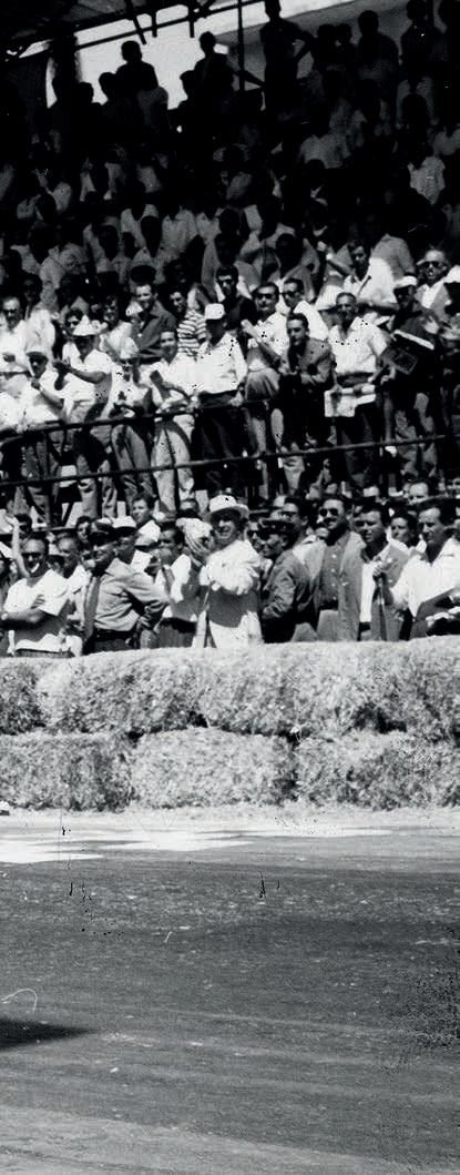
The epiphany that changed Vandervell’s life was the 1930 news that Clevite in Cleveland, USA had developed what it called a ‘thinwall’ bearing. It replaced the old-fashioned Babbitt bearings that had to be poured in place and laboriously hand finished to size. The new design of bearing was a snap-in part backed by a steel strip, to which a coating of copper alloyed with 25.6 per cent lead and two per cent tin was metallurgically bonded. This was then plated to a depth of 0.002in by a soft but durable alloy of lead and indium that helped the bearing cope with severe conditions.
With the help of his father, who backed him in buying the necessary production equipment, Vandervell successfully acquired the British rights to make the newfangled bearings. By 1936, he was manufacturing them in quantity at the new factory of Vandervell Products Ltd in the west London suburb of Acton. He was up and running just in time to help with wartime rearmament, working closely with Acton neighbour, Napier, producer of advanced aircraft engines.
When the BRM project was launched after World War 2 to build a British grand prix car, Vandervell was an enthusiastic backer in both cash and bearings for its ambitious V16 engine. However, he soon became disillusioned with the desultory progress of the car and the incompetence of its technical personnel. The last straw was the 1951 Italian Grand Prix, when an engine failed in practice because a filter in its oil reservoir hadn’t been cleaned after several engine failures – a catastrophic and unforgivable oversight.

Even worse, team major domo, Raymond Mays, told the press the cause was ‘bearing failure.’ This outraged Vandervell, who was at Monza for the race. His bearings could hardly be blamed if they weren’t getting oil. Incensed, he even initiated a lawsuit against Mays over damage to his reputation and, before the end of the year, had resigned from the BRM Trust, citing ‘personal reasons’.
This confirmed a decision the industrialist had taken at the beginning of 1950, which was to start a racing operation of his own. He engaged a former BRM man as chief mechanic and set up a racing department at his Acton factory. One of his engineers, Frederick / Freddie Fox, was to become intimately involved with Vandervell’s racecars.
In the meantime, Vandervell had been competing with various Ferraris in British racing. In 1952, he became BRM’s toughest rival in domestic events with a rebuilt, 4.5-litre, V12 single seater of Maranello origins.

Looking for chassis improvements, he had contacted Goodyear’s aviation division to see if it could adapt its aircraft disc brakes to his racecars. Receiving a positive response, he commissioned design work from Goodyear that would lead to disc brakes being made in his own workshops. An original feature was radial drilling in the discs for lightness and heat dissipation. Simplified and lightened, these were used on the grand prix Vanwall.
Over the 1951-’52 winter, Vandervell began gearing up his activity to take on an ambitious project: the building of a brand new car to contest the British Grand Prix. Starting with a 2.0-litre four cylinder that could compete in Formula2, he planned to build up to a 2.5-litre engine to suit the new Formula 1 taking effect in 1954.
These cars, and their successors, would be dubbed Vanwall Special at first, and thereafter simply Vanwall.
The idea of a four-cylinder engine –unusual when most F1 engines at the time were sixes and eights – came from Vandervell’s association with BRM.
At the end of the 1940s, BRM obtained a contract to build a water-cooled version of the air-cooled Norton motorcycle racing engine. By virtue of the higher compression ratio allowed by liquid cooling, it produced six per cent more power than the air-cooled original. Four times the Norton’s 499cc made 2.0 litres, good for a starting point.

With this experience under his belt, Vandervell started work on his first original design, intended for the 2.0-litre F2 racing class of 1953. At first, his team was mainly concentrating on engine creation, so the chassis and driveline were patterned after Ferrari ideas. This meant front suspension by parallel wishbones and a de Dion rear suspension, both sprung by transverse leaf springs. The frame was special, built by Cooper and designed by that company’s Owen Maddock, who gave it some elements of the increasingly popular spaceframe.

The rear transaxle was also Ferrari-inspired, placing its shafts flat in unit with and ahead of the differential. Initially a four-speed unit, a fifth starting gear was added in 1956. More than any other factor, the position and size of this transmission forced the Vanwall’s driver to sit high up in the air.
A small but significant change from Ferrari practice was mounting the rear brakes inboard next to the differential.
At the beginning of 1956, Porsche was asked to design synchromesh for this transaxle, which it did with its usual split-ring
design under its Project 687. Just why this was done was not certain, for drivers generally liked fast dog-clutch changes that took little effort in contrast to synchromesh, which added resistance. That was certainly the view of Stirling Moss, who found that ‘what never improved was the agricultural nature of that hefty gearchange.’ So much so, on one drive Tony Brooks’ palm came away looking like an uncooked hamburger.
The Vanwall powerplant was a curious and conflicting combination of antique and advanced techniques. Its success was partially
ensured by its origin, which was the single cylinder, half-litre Norton engine that long kept England supreme in motorcycle and Formula 3 grand prix racing.

On a power-per-litre basis, it had always been one of the world’s great engines. Its Manx version of 86 x 85.6mm for 499cc developed an air-cooled 54bhp at 7200rpm, a valuable 108bhp per litre.
Produced in Vandervell’s Park Royal tool rooms in London, the engine was composed of a high-topped, deep-walled, aluminium alloy crankcase, into which the individual cast iron cylinders were deeply spigoted. A shallow cylinder head of high-strength aluminium, with separate cam boxes and exposed valve springs, was bolted to it using 10 high-tensile steel bolts that tied into the main bearing caps.

Nestling inside the tie bolts, and topped and bottomed by rubber sealing rings, the cast aluminium water jacket steadied and sealed the whole assembly. A structural role was played by the cylinders, which fitted into a radiused countersink in the head. Fire sealing at this crucial joint was problematic until 1956, when corrugated stainless steel Cooper rings were adopted.
As expected, the cylinder head layout was very Norton, with the valves equally angled at a total of 60 degrees, but with the apex of the vee subtly shifted to the exhaust side to make more room for the inlet valve.
Engine maestro, Eric Richter, who had worked on BRM’s water-cooled Norton, stayed loyal to its proven valve gear, which addressed the cam lobe with the crowned surface of a small cylindrical sliding tappet. This, in turn, pushed an adjustable cap atop the valve stem.
As in the motorcycle engine, exposed hairpin-type valve springs closed the valves. These turned out to be a weighty cross for the team to bear, afflicted as they were by random failures. ‘Before any springs were used on an engine,’ wrote Denis Jenkinson, ‘they were run on a test rig for one hour at 2000rpm, then 10 minutes at 7000rpm and 50 minutes at 4000rpm. A total of 15 hours was done on this test rig, involving something like one and a half million ‘pinches’.’
Even after all this, rogue springs still failed when the engine was tested, and when raced.
Special features included the Norton’s angled inlet porting, proven to give the mixture an energising swirl on entry. In the aluminium head, whose water jacket extended down past the mating surface with the cylinder liner, Richter exposed the exhaust valve guide to the coolant and gave it finning for extra heat transfer.
Vandervell and Richter continued their magpie approach to proven equipment in preparing their engine’s bottom end. They chose as a model a Rolls-Royce military engine, the four-cylinder, 2.8-litre B40, which powered the Austin Champ. Its conservative bore diameter of 88.9mm gave a cylinderto-cylinder centre distance that suited their plans. Indeed, the first engines followed the Rolls-Royce design with no centre main bearing, though one was later added.

Skirts of the smooth-sided crankcase extended below the crankshaft centreline, requiring only a shallow sump cover. Ample support was provided for the five main bearings and counterweighted crank. The H-section shanks of the nickel steel con rods blended tangentially with the wrist pin ends.
For 1954, the engine was fed by four grand prix-type Amal carburettors, their slide throttles raised by four quarter pulleys and cables pivoted from a shaft along the intake cam cover. Two Amal float chambers were used, suspended from rubber diaphragms, while big bellmouthed intake stacks smoothed the incoming airflow.
For 1955, Bosch fuel injection replaced the carburettors. Placed just above the magneto, the pump was driven by the camshaft gear train. Each injection nozzle was anchored by two studs to a head passage, which opened on the intake port just upstream from the valve seat. The injecting spray bounced off the back of the head of the intake valve.
Initially, fuel piping to the nozzles was by metal tubing, resulting in vibration-induced cracks and failures at dramatic moments.
Finally, an aircraft-type flexible hose was found for the job. The Amal bodies and their control system were retained to serve as slide throttles. An additional lever arm, pull rod and shaft system regulated the Bosch pump output in proportion to throttle opening.
Use of this simple yet effective injection system, developed for Vandervell by exNorton engineer, Leo Kuzmicki, was key to the engine’s high output.
During the 1954 season, the four was progressively increased in size, first to 2262cc with 91.5 x 86mm dimensions and ultimately to the full 2.5 litres allowable. Its final measurements were 96 x 86mm for 2490cc.
Inevitably, a high-speed engine of such size posed problems with vibration, which took its toll on the fuel feed systems in particular, but also other elements of the car. In spite of the best efforts of an able team, the engine was never fully reliable.
For Tony and his team, the 1955 season, for which the team had built four new cars, was sporadic at best. Wins came only for

Vandervell placed his entire chassis and body design problem in the talented hands of Colin Chapman and Frank Costin, creators of the exceptional Lotus Eleven sports racerWhile Moss won at Casablanca on 19 October 1958, Lewis-Evans (pictured) suffered severe burns from a burst engine fire, to which he succumbed soon after the race Tony Brooks (right), who set fastest lap in the 1957 Italian GP, is here being challenged by Fangio’s Maserati, clearly showing the very different handling qualities of the two cars
The complete rebuild of the Vanwall car for 1956 included Colin Chapman’s spaceframe, with the front at lower right. Light yet rigid, it marked a big step forward in racecar design

Harry Schell in short local events, the cars failing in all four grands prix contested. The elaborate induction arrangements were a consistent source of retirements.
Feeling he was not accomplishing much as a breaker of throttle linkages and injection pipes, Hawthorn returned to Ferrari mid-year. In preparation for 1956, the specialists were consulted. Harry Weslake, Britain’s resident expert on gas flow, took over the detail development of the engine, while Daimler Benz and Robert Bosch provided useful hints on the art of methanol injection.
Vandervell placed his entire chassis and body design problem – a weighty package – in the talented hands of Colin Chapman and Frank Costin, creators of the exceptional Lotus Eleven sports racer. Though these gentlemen were not at the time familiar with the speed spectrum of an automobile ranging upward from 120 to 190mph, they were endowed with good sense and a willingness to learn.
Chapman’s contribution was the re-distribution of components and the creation of a lightweight chassis to hold them together. His frame was a very deep, spaceframe-type assembly of a few moderate-sized tubes, the principal ones just 1.25in in diameter, placed to do the maximum amount of work. A stressed, drilled sheet low at the front kept the original Vanwall wishbone assemblies rigidly aligned, now fitted with coil springs, while a pyramidal cowl structure accepted the high bending stresses at the centre of the car. With all attachment brackets, the frame balanced 87.5lb.

The steering box was high up, next to the right hand front suspension group, attacking the wheels through a three-piece track rod. Extending forward virtually parallel with the wheels and inboard from the knuckles, the I section steering arms gave negligible Ackermann effect. The Vanwall’s steering was almost disconcertingly light as a result.
The car’s De Dion rear suspension was retained, but completely re-interpreted by
Chapman. Ferrari-style parallel trailing arms were lengthened and repositioned, while a Watt’s link system served for lateral location.
High above the hubs, a slim, five-leaf spring was transversely mounted between rollers, as originated by Ferrari for racing, to increase stiffness in roll.
From the first, brackets were provided for the anchoring of coil spring and damper units, which replaced the leaf springs at the end of 1956.
Intense research during 1957’s practice periods, including valuable days spent at the Nürburgring, minimised the new layout’s teething troubles, namely front-wheel patter and a hesitant transition to four-wheel drift.
Detail improvements, including a change from Armstrong to Fichtel and Sachs dampers, allowed Stirling Moss (a team driver from the start of 1956) to fling the Vanwall around like a Cooper in 1957’s Pescara Grand Prix, which he won while taking fastest lap.
‘To enhance rear-end grip still more,’ said Moss of Chapman, ‘he gave the rear wheels three degrees negative camber, leaning inward at the top. This also made them even more convenient as footsteps to help us climb into that high, deeply screened cockpit!’
Frenchman, Maurice Trintignant, on the team in 1956, was shorter than Moss and, when he first tried a Vanwall at Monaco, was dismayed at having to look through its high, curved windscreen. He was no happier when told its height determined the volume of air drawn over the rear brakes, so it couldn’t be changed. This was typical of the taut, rigorous way Frank Costin integrated a body with his great friend’s chassis.
Trintignant’s season, by the way, was a washout, with retirements in all four entries.
A striking feature of the Vanwall’s radical aluminium ’shell was the thorough attention given to underbody streamlining. Combined with its upper contours and high tail it helped reduce the effects of side winds. The fullyshielded cockpit also had benefits in comfort for the drivers, but drawing the rear brake air upward accounted for their chimney sweeplike complexions at the end of a long race.

Ducting was ascetically simple. A trapezoidal hole let air down through a mesh screen into the glass fibre (once aluminium) airbox shrouding the Amal intake stacks. Cockpit vent scoops were built into the rear view mirror housings, while radiator air found its way out to the low pressure areas at the front suspension apertures. Costin showed the great potential available in reducing the size of the radiator air inlet as far as possible.
The main 39 gallon fuel tank was in the tail, strapped to a triangulated frame extension. Two 15-gallon auxiliaries were slung outboard on either side of the cowl, an arrangement similar to that of the original Vanwalls. Heavy flex hoses joined the three
tanks at a selector valve on the right of the cockpit. A fuel filter and pump were mounted at the engine’s left front, belt driven from the nose of the crankshaft.
Early Vanwalls had impressive but overbearing engine-turned dash panels, which gave way to a less blinding flat black finish in time. Instruments were tachometer, either 8000rpm Jaeger or 9000 rev Smiths, oil and water temperature, oil pressure and fuel pressure. Gear lever was at the left, emerging from a simple gate atop a massive cast housing. A tiny handbrake was at the right.
Vandervell enjoyed a drive in the transformed Vanwall before it received its distinctive dark blue-green livery. Then it was handed to Stirling Moss: ‘I first tried it briefly at Silverstone on 10 October,’ he recalled, ‘my diary assessing it simply as bloody quick.’
The team then took two cars to Oulton Park on 22 October for a grand prix distance test.
‘I drove one for one hour 50 minutes until its suspension broke, and the other for two hours 30 minutes until an injector pipe broke,’ Moss continued. ‘I certainly had many reservations, but this was clearly the first green grand prix car I had ever driven that showed such winning potential.’
Although still sceptical about the Vanwall’s staying power, Moss signed with Vanwall for the 1957 season. Though committed to racing Maseratis in 1956, he drove the Vanwall in the non-championship, 176-mile BRDC International Trophy race at Silverstone on 5 May 1956, sensationally winning from pole by a lap after Ferrari’s two entries retired.
Franco-American, Harry Schell, led the Vanwall attack in 1956, in which 12 starts in four grands prix produced only one decent finish, a fourth at Spa for Schell. With reliability all but non-existent, the team had much to do to prepare for Moss’ arrival in 1957, together with Tony Brooks.
During 1957, Vandervell froze the basic design of his cars, tasking his designers with
creating specialised editions to suit particular circuits, as Mercedes-Benz had done in 1955. One example was pug noses and nerf bars for the Monaco team cars after two of the team’s cars had been forced to retire prematurely in ’56, their long snouts dented during early lap infighting and engine cooling suffering as a result.
Most outlandish of all, though, was the Reims ‘streamliner’, Costin’s highly original interpretation of a racecar. Its front wheels were fully enclosed by sweeping wings, pierced at the nose by three intakes for brakes and engine. A clamshell-like lid capped each rear wheel. The impression was of a vehicle that might easily become a potent sports car if its builder willed it, although this was unlikely, at least in that form.
Evaluation of the Reims variant was vitiated by confusion over gear ratios and engine power, and so it was not used at the race, or indeed ever. Nor was another successful aerodynamic aid, a complete Perspex enclosure for the cockpit made for Monza in 1958. It may have given an additional 50rpm on the straights but, even with earplugs, it intensified the racket in the cockpit so much it was set aside.
Moss missed some races in early 1957 owing to ill health, which for team manager,
‘To enhance rear-end grip still more he gave the rear wheels three degrees negative camber, leaning inward at the top’
Stirling Moss on Colin Chapman









David Yorke, opened an opportunity for a relative newcomer, Stuart Lewis-Evans, to step in and show considerable promise.
A highlight that year was the British Grand Prix at Aintree on 20 July, which Stirling Moss won in the car started by Tony Brooks. This made the Vanwall the first British car to win a race for World Championship points. Moss won again at Pescara and Monza, finishing second to Fangio for the third year in a row in the Drivers’ Championship.
Big changes in the Formula 1 rules for 1958 did not favour Vanwall. Previously unrestricted, fuel would now be 100 / 130 octane aviation petrol. Points scoring races were reduced in length from 500km or three hours to 300km or two hours. Drivers could also no longer score points after jumping from one car to another.
Other things being equal, the most successful petrol-fuelled engine was the one with more cylinders, hence smaller combustion chambers that can swallow higher compression ratios without preignition. With just four cylinders, Vanwall was disadvantaged against the 1958 V6 Ferrari and the straight six and V12 Maseratis. From 12.5:1 on methanol-based fuel, the compression ratio had to be reduced to 11.5:1 for 1958. At that time, an oil jet was added to cool the underside of the piston crown.
On its original methanol / benzol-based fuel, the Vanwall’s peak power was 285bhp at 7200rpm and, with a tip of the nitromethane can, 295bhp. In 1958, on 108 / 135 octane BP petrol, the four produced 265bhp at 7400rpm. Less outright power, but still a tribute to the effectiveness of Park Royal’s development of this big bore engine.
In 1958, the Vanwall was pitched against Ferrari’s new, smaller 246 F1 Dino, and the
rising threat of the Coventry-Climax FPF four in its interim 2.2-litre size, powering pesky little Lotuses and Coopers. In fact, CooperClimaxes won the first two points races. The third, however, went to Moss at Zandvoort, and the fifth to Brooks at the Nürburgring, where the team had struggled in 1957. Moss was second at Reims and the winner at Porto and Casablanca, while Brooks won at Monza.
‘These basically stable understeering cars had to be driven between very precise limits,’ Stirling Moss observed later. ‘They were never as forgiving, indeed delightful, in their handling characteristics as the essentially oversteering Maserati 250F.
‘I rarely found another car so sensitive to damper settings and fine tyre differences, but the change from transverse leaf spring to coil spring rear suspension had undoubtedly been a great leap forward.’
The 1958 result was second and third in the Drivers’ Championship for Moss and Brooks respectively, and a decisive win for Vanwall in the Constructors’ Championship, with 48 points for Vanwall against 40 for Ferrari.
January 1959 saw two retirements, Mike Hawthorn’s after his Drivers’ Championship, and Tony Vandervell’s after his team’s magnificent demonstration of power and speed in winning the Constructors’ Cup for Britain. The latter was awarded the RAC’s Dewar Trophy and Ferodo’s Gold Trophy for his team’s achievements.
Unable completely to damp his flames of enthusiasm for motorsports, Vandervell still tinkered with machinery at Park Royal. He had two projects on the boil: a slimmeddown version of the existing car with a new rear suspension and transmission designed by Valerio Colotti, and a new, rear-engined Vanwall built around a Lotus 18 chassis.
Enthusiastic about the latter, Tony Brooks agreed to test and race for Vandervell in 1959 as required. He was to be disappointed.
The rear-engined Vanwall made little progress while Vandervell ‘was still spending time trying to develop the old front-engined car,’ recalled Brooks, ‘which now really ranked with the dinosaurs in F1 terms.’
He raced the new car on just three occasions, once in 1959 and twice in 1960, but only finished in one of the races, and even then only in seventh place.
In 1959, Brooks had a chance to test the Lotus-Vanwall prototype and lost no enthusiasm for the idea, but Vandervell set that aside and built a new, more robust car along similar lines. However, that did not appear until 1961, to compete in the new Inter-Continental category formed to let the old 2.5-litre cars keep racing after Formula 1 had switched to 1.5 litres in 1961.

A purposeful-looking car with a 2.6-litre engine, it was driven by John Surtees in the 263-mile International Trophy race at Silverstone on 6 May. He found it ‘skittish’ in the wet race and spun off, needing a pit stop to clear greenery from its snout. Falling back to 13th place, Surtees provided the event’s main interest by climbing up to fifth at the finish. Though it clearly showed promise, at least in the right hands, that event was to be the car’s only public appearance.
Health had been one of the main reasons for Vandervell’s withdrawal from the stressful business of Formula 1 racing. Instead, he turned his attention to Vandervell Products, which became a public company in 1964. Three years later, one of the most colourful and forceful individuals to lift the standard of British motor racing died. Neither Vandervell, nor his unorthodox but fast racecars, will ever be forgotten.
‘These basically stable understeering cars had to be driven between very precise limits. They were never as forgiving, indeed delightful, in their handling characteristics as the essentially oversteering Maserati 250F’
Stirling MossHandsome though it was, the mid-engined Vanwall of 1961 was a radical departure in design for the team, but could not challenge its rivals in that year’s Inter-Continental series. The series died soon after, and the last Vanwall with it


Whether in motorsport or mainstream automotive, battery technology remains the most vexing, and expensive, stumbling block on the path towards range and price parity with ICE vehicles. While an electric motor, power electronics and associated transmission can easily out gun ICE in terms of powerto-weight ratio, even without having to resort to the exotic end of the market, batteries are – to put it bluntly – fat and heavy. However, the situation is already very much advanced from where it was a decade ago, and marching forward at a pace.
Think back to 2014, when Formula E needed two stage races, with drivers swapping cars, to the situation that will (if all of the parts work as advertised) see cars run full races, at a higher power output, using a significantly smaller (in both size and capacity) battery when Gen 3 arrives next year. Admittedly, this is not solely thanks to the battery. Increases in overall vehicle efficiency, coupled with 150kW of front axle regeneration are vital, but the fact remains the Gen 3 battery is far more energy dense and efficient than those in the series’ Gen 1 cars.
This situation applies across racing, from full EVs such as Extreme E and ETCR to the hybrids running in the WRC and WEC, all of which have benefitted from the increase in power density of batteries, coupled with better packaging and improved levels of efficiency.
As was addressed in Racecar Engineering V32N2, lithium-ion-based battery chemistries remain the standard for high performance applications, and all operate on the same basis. The focus of this article is battery control, but it is worth briefly recapping how a such a battery operates.
During charging and discharging, lithium ions pass between an anode and cathode via an electrolyte, and the make up of these
elements dictates both the energy and power density of a given chemistry. The former hinges on maximising the amount of active material in a battery, the latter on reducing the resistance the ions experience as they move between the electrodes. Unfortunately, these two goals are somewhat mutually exclusive, so the more material for the ions to pass through, the higher the resistance.
Formulating the chemistry for a particular task is therefore a case of trying to balance these competing demands, combined with designing a complete battery pack and incorporating the cells, cooling and management system that mitigates issues such as temperature build up under load.

With short-duration, high-load scenarios, battery chemistries can be tailored towards power density. The battery stores a relatively small amount of energy for its size, but is able to discharge it very quickly. In these situations, simple air cooling of the exterior of a pack can be sufficient, combined with pre-cooling of the pack prior to an event. This is the approach taken by Williams Advanced Engineering (WAE) with the pack it supplies into Extreme E.
Conversely, where a battery needs to operate over a longer duration, either at a higher power level (such as the ERS battery used in F1) or at a lower power level while holding a useful amount of energy (think Formula E), a different chemistry will be used, coupled with most likely either indirect or direct liquid cooling.
The degree of sophistication of the cooling systems can vary but, in general,
How the systems that control racecar batteries are rapidly developing in line with new regulations for e ciency and minimum life requirements
The degree of sophistication of the cooling systems can vary but, in general, the smaller the packaging envelope and the higher the power output of the battery, the more complex the system needs to beNXP Semiconductors
the smaller the packaging envelope and the higher the power output of the battery, the more complex the system needs to be.
Direct or immersion liquid cooling is one area of particular interest for motorsport applications. While it does introduce considerable complexity into the construction of a pack, it is exceptionally effective for heat removal. In our previous article, we covered the solution derived by Kreisel, deployed in the WRC and WRX, which uses immersion cooling of 21,700 cells (which are becoming established as a favoured high-power cell), housed in a ‘Hollowblock’ structure with 3M Novec dielectric fluid flowing around each cell.
There are plenty of other immersion cooled battery systems under development. For example, UK-based Sprint Power is looking to commercialise a modular battery concept that places a 5kWh pack, complete with BMS, immersion cooling and integrated pump within a single housing. Capable of a peak discharge rate of 230kW over five seconds, or 105kW continuously, the pack is aimed at use in hybrid vehicles.


The high C-rate is achieved through the use of both immersion cooling and very high-power cells from another UK firm, AMTE Power (which, among other projects, provides the batteries for Gordon Murray’s T.50 supercar). These are pouch cells and, according to the company, are capable of 35C continuous discharge. Notably, Sprint Power has been working closely with Castrol, the brand of BP responsible for lubricant and coolant development, on immersion cooling fluids for EV applications.
According to Marc Payne, senior research manager for EV fluids at Castrol, the company has been putting considerable effort into the development of single-phase battery cooling fluids (others such as Novec are two-phase fluids, which rely on evaporation as part of the cooling process), focussing on aspects such as viscosity reduction to cut pumping losses (without increasing the volatility of the fluid), while also upping the specific heat capacity.
Recognising the role sustainability now has to play in almost every aspect of automotive development, Payne also pointed out that the latest fluids were being developed from sustainable feedstocks, with attention paid to how they can be reprocessed at the end of their useful life.
Regardless of the chemistry used, the layout of a pack or the cooling regime, a battery is useless, not to mention dangerous, without an effective battery management system (BMS). The role of the BMS is a complex one. It is primarily responsible for monitoring the state of charge (SOC) and state of health


(SOH) of the battery and balancing the voltage of cells across the pack. It will also dictate the operation of ancillaries such as coolant pumps, while monitoring coolant inlet and outlet temperatures and activating cooling fans, as well as communicating with the vehicle control unit (VCU).
Starting with temperature management, a BMS must ensure there is an even temperature distribution across all of the cells in a pack, while keeping them within the narrow temperature band where they operate most efficiently. Even advanced chemistries do not like being much hotter than 60degC and most prefer operating below 40degC. A very slight temperature increase over the optimum can result
The role of the BMS is a complex one. It is primarily responsible for monitoring the state of charge and state of health of the battery and balancing the voltage of cells across the pack


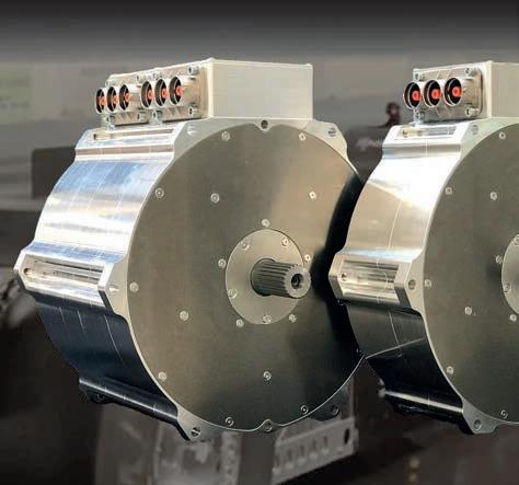

in significant drops in efficiency, while excursions up to maximum survivable temperatures can halve efficiency. Operation at high temperature also has long-term effects on battery performance, and with most race series now specifying minimum life requirements for components, including packs, this is an important consideration.
The BMS will monitor and control the temperature across the pack in a number of ways, while also determining whether temperature rises are a result of normal operation, or indicative of a looming issue (for example, by registering unexpected current draw). The majority of BMS to date, particularly those found in automotive applications, rely on temperature measurement at a module level, which is sufficient under relatively benign operating conditions, but not ideal when pushing a pack to extremes, ie racing.
The perfect solution is individual measurement of each cell, but this involves the use of separate sensors (such as thermistors) and associated cabling for each cell, considerably increasing the complexity, and weight, of the pack. Fortunately, there are solutions under development to mitigate this. For example, German company, InnvationLab, has developed a thin foil sensor for use with both pouch and prismatic cells, with the sensor placed between each cell. The sensors are multi-role and can record both pressure and temperature, with the latter obtained using a temperaturesensitive resistor printed onto the foil.
Furthermore, the sensors do not simply provide a spot reading, they record the temperature distribution across the cell. Where packaging space and weight is of primary importance, it may not be desirable to integrate even thin film sensors into a pack, but they can still be used during development to gather data, which can in turn be used to refine the models used to monitor and control pack operation.
Current and voltage monitoring at both a cell and pack level is similarly vital to the operation of the BMS. This is achieved in a variety of ways. The most popular method of current measurement is via shunt resistors coupled with a signal conditioning device, creating current measurement circuits that literally count the coulombs of energy in and out of a battery during charge and discharge cycles. Current measurement can also be achieved with magnetic Hall effect sensors, which have a number of advantages over shunts. Notably, they can record both AC and DC current. However, they are low band width and susceptible to drift as temperatures change, meaning they need to be employed judiciously.
Multi-physics simulation of batteries is necessary to understand the thermal and physical behaviour of a pack. The results can then be used to inform the battery control module


The perfect solution is individual measurement of each cell, but this involves the use of separate sensors and associated cabling for each cell, considerably increasing the complexity, and weight, of the pack




One interesting development that addresses the issue of wiring complexity and data transfer requirements of individual cell monitoring is the application of wireless sensors. Dukosi, a Scottish company specialising in battery systems, has developed a chip-on-cell battery monitoring system that relies on NFC (near field communication) to transfer cell health data to a single low voltage wire loop that runs around the battery pack. Each cell is fitted with a CMOS chip, powered by the cell it is attached to, and data on battery voltage and other parameters can be quickly transmitted to the BMS.
The various interactions within a battery during charge and discharge are complex and interlinked, and central to the operation of the BMS will be a model, used as a reference to ensure all the monitored parameters are within bounds, and the battery is performing as expected, and at its most efficient. It is in the development of these control models that some of the greatest advances in battery capabilities have arisen in recent years.
Simulation and modelling are central to the design and operation of any battery system, from developing initial chemistries through determining pack layout to the running of the BMS. In the case of the latter, all the inferences the BMS relies on to ascertain battery health depend on the battery model. A well-developed model will result in an
efficient and reliable battery, while any shortcomings will invariably lead to issues.
The first building block of a battery management model will be an electrochemical model, mapping out the reactions taking place in the electrodes and electrolyte. These models range from the relatively simple to very complex, depending on how many factors they consider. For example, the influence of mass transfer rates on the reactions taking place, or differences in concentration of the electrolyte at reacting sites. Primary and secondary current distribution models generally assume concentration is constant through the electrolyte, and mass transfer is not a limiting factor on reactions. For high loads, which motorsport batteries will be subjected to, these limitations must be accounted for, using what is called a tertiary current distribution model. All these models need to be validated via experiment to ensure modelled values marry up with reality.
With an electrochemical model established, the myriad other multiphysics processes in a battery must also be considered, from fluid and current flows to the effects of temperature variations. These models should be able to identify any problem areas, such as non-uniform temperature distribution, with the structural impact of any issues to do with electrode structure, cell integrity or more assessed using FEA. Areas such as coolant flow,
either through cold plates of a pack or, if direct cooling is used, between the cells will also be assessed via CFD.
The end result of a successful modelling programme should, in theory at least, allow for a battery to be run as close as possible to its potential maximum energy or power density in a safe and reliable manner. Fortunately, in recent years software companies have developed dedicated simulation packages that make the task of undertaking complex multi-physics battery modelling less daunting. Ansys, for example, offers a suite of products that address everything from electrochemical modelling to structural simulation.
Ansys worked closely with VW Motorsport on the development of its ID.R Pikes Peak racer,

The end result of a successful modelling programme should allow for a battery to be run as close as possible to its potential maximum energy or power density in a safe and reliable manner


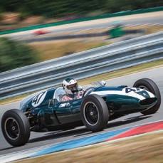
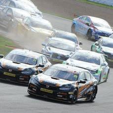

using its full arsenal of tools to develop a digital twin of the car’s battery pack. Using Ansys Twin Builder, a six-step, multi-physics simulation was conducted involving electrical and thermal parameters to design and validate the battery model. The first step was to develop an equivalent circuit model (ECM) for a single battery cell, in effect simplifying a complex circuit to aid analysis speed. Test data was obtained from a pulse discharge using a single cell to obtain all the parameters needed to calibrate the ECM and verify the single cell model was created correctly. Highlighting the usefulness of a simple model, the simulation of the ECM only required a few seconds to complete a full drive cycle of the ID.R up the Pikes Peak course.
ECMs representing each cell were then combined to form a virtual battery module before CFD simulation was conducted to simulate the thermal properties of the battery, to create the data needed (in conjunction with the ECM) to ascertain battery performance across its operating temperature range.

In order to simplify the process of running the ECM and CFD models in a coupled multi-physics simulation, the key thermal characteristics were extracted to create a reduced order model (ROM), which
correlated well with the CFD but could be run much quicker. For reference, the CFD simulation took 48 hours on 100 cores with a mesh featuring 67 million cells.
Running the two models in a coupled simulation, the ECM was able to predict the electrical performance and heat generated, while the ROM thermal model used this heat generation value to predict cell temperature, which was then transferred back to the ECM model to determine its effect on electrical performance. The iterative process was repeated until a solution was converged upon.
Finally, a further model was built to simulate the operation of the complete 10-module battery pack, to predict its voltage and current output over the course of the run, and ensure it stayed within its safe operating limits. As witnessed by VW’s record-setting run with the car, the modelling effort paid off.
Suffice to say, battery modelling is fiendishly complex, but there are an increasing number of tools available for engineers to lean on. This is also true of the resources on the market to validate the models. For example, dedicated battery test cells allow for hardware and software-inthe-loop testing of models in conjunction
with the BMS, or even the entire drivetrain, under close to real world conditions.
Overall, advanced battery technology, both in terms of the building blocks such as cells, as well as the components needed to manage them, are becoming more accessible beyond the rarefied heights of works teams and top race series. It is also the case that automotive-grade technology has advanced to the point where it is practical for use in some racing environments.
While ICE competition will undoubtedly remain for some time yet, accessible electric motorsport at a national championship level is nearing reality.
state
also
Dedicated battery test cells allow for hardware and software-in-the-loop testing of models in conjunction with the BMS, or even the entire drivetrain, under close to real world conditions


The advancements in engine control units (ECUs) over the last 40 years have played a large part in re-shaping the tuning and vehicle control landscape. Not only have developments in this field made contemporary racing and production engines more efficient and more tractable, but the modern ECU offers failsafes, accurate systems modelling, greater systems integration and a range of other features that require evermore focus and attention from the systems calibrator. What we used to call a tuner.
In this article, we look at some of the recent developments in ECUs that have broadened their range of applications, as well as some of today’s more intriguing calibration challenges.


Basically, the ECU consists of a processor that uses a pre-programmed map that
monitors inputs and controls its outputs thousands of times per second, offering precise control of the fuel injection and ignition of a modern engine.
In slightly more detail, the ECU contains a printed circuit board (PCB), upon which microcontroller chips and the central processing unit (CPU) are mounted. The software is stored in flash memory. Thirty-odd years ago, a simple software update required replacing the chip, but advancements in flash memory made in the 1990s now allow for re-programming of the chip without altering the physical make up of the ECU.
In addition to monitoring the position of the engine, firing of the ignition coils and fuel injectors, the ECU has taken on many other roles over the years. These days, it
acts as a complete vehicle control unit. Various inputs are typical in modern ECUs, and can be classified into several basic groups. These include digital inputs, analogue inputs and communication inputs like RS232 or CAN. Examples of typical analogue inputs are variable resistors like temperature sensors, potentiometers, switches and voltage generators.

The ECU consists of a processor that uses a pre-programmed map that monitors inputs and controls its outputs thousands of times per second
ECUs have come a long way in the last 40 years. Racecar looks at the developments that have led to a new de nition of the word ‘tuner’
Magnetic / Hall-effect sensors are a frequently used type of digital input.
This information is then directed by the ECU towards a multitude of outputs. Some examples include open collector low current relay drivers, as well as halfbridge and full-bridge drivers that can directly control components like small motors. There are also high voltage injector drivers for modern direct injection, as well as communication-based outputs
designed to interface with other modules via either CAN or Ethernet.

Modern demands for power, efficiency, traction management, aerodynamic adjustments and more complicated powertrains have increased the general number of sensors in any given racing vehicle. This means more inputs and outputs, which have forced the ECU’s processing power to grow proportionally.
Over the last two decades, the ECU has made strides forward in two particular areas. The number of controllable elements has grown, as has the speed with which the ECU responds, largely due to increased processing power and improved programming capabilities.
Additionally, this has allowed teams of relatively small size to write custom algorithms into the code for their ECUs. Not surprisingly, greater access to something which OEMs once held dominion over has changed the game.
ECU tuning once entailed purchasing an ECU with pre-set tables and parameters that were mostly fixed. Some would offer very limited flexibility to create custom tables with user-defined axes, but truly customisable control systems implementation was not readily available.
Now, the working environment has expanded by offering the end user, or their calibrator, the opportunity to shape their own code and write their own control strategies. MoTeC’s M1 Build is just one example that has grown in popularity over the last decade.
M1 Build allows the tuner to make custom channels, parameters and tables all in their own custom control strategies. Within this development environment, privateers now have the ability to finish one-off projects within short time frames, and without the need to hire a dozen engineers.

This means small teams can avoid becoming mired in the myriad minor, but no less significant, jobs of low-level programming, building a microprocessor, de-bugging or just working in an environment not suited to motorsport.
Now, all privateers have to do is write simple snippets of code. They can then interface with drop-in sensors, tables, parameters and channels. All the unit conversions and common maths functions are provided, allowing the user to quickly implement their goal strategy without spending time worrying about the repetitive, mundane aspects of C-level programming.
‘Compare designing a control strategy to building a house,’ says Sasha Anis, general manager of MoTeC Canada and founder of Mountain Pass Performance, a tuning house specialising in EVs. ‘These
Privateers now have the ability to finish one-off projects within short time frames, and without the need to hire a dozen engineersA straightforward interface, broad view of parameters and the ability to modify values in real time make MoTeC’s M1 Tune popular Magneti Marelli
ECUs allow you to buy the wood from the store, if you will, instead of having to grow the trees and mill the wood yourself. Basically, it gives the user the building blocks to create an effective control strategy paired with a high level of robustness.’
MoTeC’s M1 Build uses a tree structure to represent logical subsystems and define naming of these systems, which carry through to the tuning interface. The code is then compiled into a package, which is then loaded onto the ECU. In addition, there are pre-provided modules that can be used in a drag-and-drop fashion to quickly implement elements like common sensors, tables, parameters and communication modules.
A user can drag and drop these modules into their own bespoke tree structure to create their own ECU subsystems.
‘Essentially, the user can now devise their own control strategy, while still benefiting from the safeguards of the system,’ continues Anis. ‘It won’t allow you to break the core function of the ECU. You can still have logic errors, but you won’t fundamentally take down the ECU.
‘You just drop in a table, and it does all the necessary interpolation, limit checking and value validation for you.’
With M1 Build, the user is given access to the code. If they need to write a specific module to run the car, the user can drop into a modularised interface mode and write the code and make their own
firmware. Following this, the user will use MoTeC’s M1 Tune to move forward.
M1 Tune is software that provides the user the ability to interface with the firmware developed in M1 Build. In M1 Tune, the user can look at all the parameters and tables and modify the values in real time, just as one would expect of a modern ECU.
However, many motorsport outfits are now trying to design their control strategies in house, much like the OEMs. One program, Simulink, allows teams to run control strategies in a flow chart style. They add the various blocks, and Simulink compiles these blocks into an application.
Simulink’s popularity has expanded its use in everything from FSAE programmes to Bosch ECUs used at the higher end of motorsport. This is due to two traits: its intuitive interface and its modular code.

‘Simulink doesn’t require you to be skilled in C-based code,’ says Hannah Westbrook, an engineer for Honda Performance Development, who started using the program at university and participating in its FSAE initiative. This accessibility is largely due to Simulink’s block-based diagrams. Its intuitive interface shows each block representing an easily comprehensible value such as greater than, less than or equal to. This allows programmers to put together strategies without writing code-based statements.
‘When choosing between ECUs, you have to ask a lot of questions,’ says Westbrook. ‘How many sensors and analogue inputs do you need? What is the processing power
required? Do you want to run your own injector or ignition box? The answers to these will narrow the options down to a few.’
‘Then you ask how many cores can your processor run? If you’re limited by your number of cores, you have to ask them to balance tasks with other cores and, in turn, you spread them thinner. However, more processor function means more power, which means more heat.’
The list of considerations goes on, endlessly it seems. More sensors mean more wires, which adds to the overall weight. The user must then ask how much weight can be shed from other areas to achieve an overall target weight. Incidentally, there are Bluetooth sensors available now that can reduce wiring weight, but their number is often limited by the regulations for safety reasons.
‘Essentially, the user can now devise their own control strategy, while still benefitting from the safeguards of the system’
Sasha Anis, general manager at MoTeC Canada and founder of Mountain Pass PerformanceWith hybrid units now commonplace in race series, ECUs have had to adapt and offer teams a higher level of flexibility to run these complex systems in tandem with internal combustion engines Mountain Pass Performance


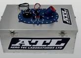


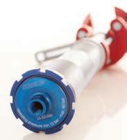
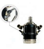


Weight can also be reduced by running CAN expansion boxes, which often require a larger collection of shorter wires, with only two wires between the expansion and the main ECU. This reduces weight, but this also increases the processing power demands as CAN is more processor heavy than analogue signal sampling, and the more sensors added on CAN, the more CAN buses needed. As they say, there’s no such thing as a free lunch.
The engineer’s preferences and past experience also play a part in the decision making process. ‘For instance, how is the ECU programmed (Simulink, etc)? Who do you have a good working relationship with? Though these considerations aren’t always primary factors in deciding which ECU is used, they do make a difference in softening the slope of the learning curve,’ Westbrook adds.
The processing power and sheer number of channels being worked with in real time with modern ECUs has grown enormously in recent years. So much so, in fact, that Ethernet is now necessary for effective communication between ECUs.
Telemetry channels in the modern racecar are now transferred via an RS232 signal or an Ethernet signal, with the occasional CAN bus signal. On the other end of it, as long as there’s a decent connection, there’s a telemetry server needed to receive and decrypt that information.

Getting information from the car to the pit stand has been made much better with 4G technology, though the activity of the crowd on their ’phones and tablets still compete. It really depends on the configuration of radio towers around the track.
Password protection is nothing new with ECUs, and there are a number of scrutineering programs that enable detailed file overlays to reveal any tampering. Still, there are a great number of clever saboteurs out there. To further safeguard information, a metadata file is used. Competing teams cannot spectate a telemetry stream if they don’t have the necessary metadata file.
Other safeguarding measures include an encryption key that, even if it’s visible, the data stream is indecipherable without.
With the widespread interest and prevalence of hybrid powertrains currently, most popular ECUs in high-level motorsport will need the versatility to handle the additional challenges posed by electric motors.

Now with Honda Performance Development, Westbrook is involved with systems integration of LMDh hybrid cars for IMSA competition. These cars run a Bosch MCU (Motor Control Unit) and MGU (Motor Generator Unit), both of which are series mandated. However, the McLaren ECU strategy with the hybrid
system integration is still largely up to the team to design and compile.
There are different strategies to deploy and regen’ the hybrid power and, thankfully, it has some flexibility so the manufacturers can continue to refine their control strategies. However, that does not change the fact that these systems are highly complex and, in order to run them, many considerations must be made.
Considering the inherent dangers of working with high voltage systems, the BMS (Battery Management System) needs to be extremely thorough in monitoring cells and high voltage isolation from the rest of the chassis. Not surprisingly, this also requires many sensors.
Additionally, ancillary systems must be monitored extra carefully when dealing with regen’ and deployment.
‘With an EV, you have to be cognisant of when you deploy the energy and ensure it will not compromise a related area. For instance, will the braking system handle the extra challenges of harvesting?’ Westbrook queries.
‘After the driver’s requested brake pressure value is sent to the electronic braking system, it will take that value and split it between the MGU and the brakes. We must ensure the proportion of brake pressure used to slow the car will always be sufficient,’ she explains.
Beyond ensuring safety, the ECU’s general aim in this environment is achieving greater efficiency. And to do this, elements like the MGU and the ICE must be kept operating in their own ideal efficiency ranges.
‘How the algorithm is written in this instance is vital, since getting the two to
CAN is more processor heavy than analogue signal sampling, and the more sensors added on CAN, the more CAN buses neededThe inherent danger present in any high-voltage system means the cells must be closely monitored at all times An inverter, DC DC converter and power distribution module mounted inside a hybrid Time Attack car
communicate clearly requires a lot of careful implementation,’ adds Westbrook. This is obvious when discussing the trade off taking place when a mildly compromised hybrid has to deliver a torque request.
For instance, the BMS monitors battery parameters so, if the battery becomes too hot, it changes the maximum allowed charge and discharge rate. The BMS then informs the ECU so it can adjust its strategy. In further detail: in order to make sure the
ICE and the electric motor respond well to a torque request when battery power dwindles and cannot provide the desired amount of electric power, or if the system is harvesting and not able to fully deploy, the torque request will have to ask the combustion engine to compensate for the electric motor’s reduced offering and meet the torque request. This feature plays a large part in determining an EV’s stamina over a long haul.
‘What do I think we might see in the future?
Well, with EV in motorsport, the engine might soon become the part responsible for the ‘push-to-pass’ function, while the electric motor will play a larger part in providing the thrust,’ says Westbrook.

On the electronics side, there may soon be a ‘central box’ responsible for handling most duties, while ancillary duties, say injector drivers, will be sent on CAN via a specialised ‘injector box’. This relieves the central box of certain duties that could be delegated in the name of greater efficiency.
This could help both the manufacturers and the customers. Not only could it be easier for the manufacturers to build these bespoke boxes, but it would allow the customer a more modular and customisable product.
Will modern ECUs make it easier for alternative fuels to be embraced? ‘Absolutely,’ declares Westbrook. ‘The foundation has already been laid and ECUs can easily adapt to these changes. Most of the necessary sensors are already onboard, so the concerns would be primarily around pressures and whether the fuel system and cylinders could handle them.’
Advancements in electronics in the last 30 years have made customisation possible where it was once prohibitively expensive, or difficult to deploy. Systems such as fourwheel steering, DRS and EBS have all been made possible by the increase in processing power of ECUs. Now, with the ability to create custom control strategies, the landscape has opened up further still and a vast number of clever control strategies are now available to racers looking for a competitive edge.
How F1’s soon-to-be-mandated Advanced Sustainable fuels stack up nancially, environmentally and sustainably against the alternative options
By PETER WRIGHTIn part one last month, we looked at the Advanced Sustainable (AS) fuels F1 has mandated for power units from 2026. In this follow-up article, we look at why the world needs them to replace fossil fuels for combustion in increasingly obsolete internal combustion engines (ICE) for wheeled transport, and how they stack up against the alternative options available.
Currently, a medium-sized turbo diesel car returns around 45mpg. An imperial gallon of diesel embodies 49kWh, which means it travels 0.9 miles per kWh of energy in the tank. Add a hybrid system, and the mileage can be improved by around 30 per cent to 1.2m/kWh. Both these powertrains currently use carbon that is not present in the atmosphere and emit CO2 into it. They also emit local pollutants such as NOx and particulate matter (PM), reducing air quality
in urban areas and generating increasingly apparent public health issues.
If these ICEs use an AS fuel, one that derives carbon from the atmosphere, either from plants, biowaste or CO2 capture, they become roughly net zero carbon, but still emit local pollutants.
A medium-sized EV, on the other hand, will travel 4-5 miles per kWh, so it uses its available energy roughly four times more efficiently. Provided the energy is generated from a renewable source, it is zero carbon and produces zero local pollutants.
Using hydrogen in either a fuel cell EV or an ICE car is zero carbon, provided the energy used to make the hydrogen is renewable. NO x will be emitted by a hydrogen ICE but no PMs. A fuel cell EV is therefore inherently as efficient as a battery EV, but the conversion of hydrogen into electricity in the fuel cell is only
about 60 per cent efficient, therefore the miles per kWh are reduced to 2.5-3. A hydrogen-fuelled ICE is likely to be only as efficient as a hydrocarbon-fuelled version.
Other factors come into the question of which powertrain will become the most economically and environmentally desirable. The energy density, including the storage system, favours liquid hydrocarbon, followed by hydrogen, and finally batteries. These parameters determine range, refuelling time and the cost of the vehicle.
Battery chemistries and construction are currently subject to intense development, and so-called ‘gigafactories’ to produce them are springing up all over the world. There is no shortage of lithium, just a demand that now outstrips supply of the refined product.

Lithium may well be replaced with sodium and, as there is no shortage of salt, we will not run out of electrolyte. Alternative cathodes and anodes are already in production that do not require cobalt or nickel.
In China, Geely has launched a car with a claimed 1000km range and 600kW charging for a five-minute charge time. When this technology comes to fruition, it will close the gap to hydrocarbon-fuelled vehicles. Things are changing fast.

So far, we have only considered tank-to-wheel. A critical issue affecting the desirability and economics of the aforementioned energy options is the process to source / manufacture, refine/ distill and transport the energy, described as source-to-tank. These process technologies are also under intense development, but currently overall source-towheel efficiencies are as follows: battery EV – 70-80 per cent; hydrogen fuel cell – 25 per cent; e-fuel ICE – 15 per cent.
Converting the sun’s energy directly into electrons, either by photovoltaics, wind turbines or hydro-electric, and transporting
that energy via copper wires to charging points is overall around five times more efficient than converting biomass, waste or atmospheric CO2 to a hydrocarbon fuel in order to power wheels. There is no shortage of the sun’s energy, it is the best means of storing it that needs work.
Functionally, a ‘drop-in’ e-fuel will perform just the same as a fossil fuel equivalent. The difference is that the fossil fuel was created out of the photosynthes of plant matter by natural high-temperature, high-pressure processes over a long time, at no cost. E-fuels, on the other hand, use a variety of speeded-up processes requiring an input of energy roughly equal to the energy embodied. Whether this derives directly from the sun, as with algae, or from renewable
electricity, or from fossil fuel determines its cost in monetary, environmental and sustainability terms.
Already EVs are more refined, have better secondary ride (unsprung to sprung mass ratio), more performance, require less maintenance, are lower cost to run and lower cost to own after around 10 to 20,000 miles than conventional ICE cars.
Personally, along with Elon Musk, Herbert Deiss, the Chinese auto industry, Norway’s (and, increasingly, China’s, Europe’s and even now some car owners in the USA), I believe the future for wheeled transport, from micromobility to trucks, is electric. By 2030, the conversion to EVs will be well established. By then, F1’s e-fuel formula will be four years into its cycle, and maybe looking somewhat irrelevant to road transport systems, so why has the FIA and FOM gone down this route?
In 2026, when the new F1 power unit regulations apply, the industry will be halfway to the generally accepted target of 2030 when no new ICE cars can be sold. The automobile industry outside China shakes its head and claims it is not possible. What they actually mean by that is they don’t know how to make a profit making EVs, especially small ones. Nor where the investment for the new production facilities required is going to come from.
And yet, existing and planned battery production investment is 5500GWh per year by 2030 – enough for 550 million 100kWh batteries – suitable for, but obviously not all for, cars. Wheeled vehicles will only require about one third of this energy storage capacity. What they say and what they do are not the same.

automobile industry] don’t
make a profit making
small
Nor where the investment
is going to
Meanwhile, the energy industry, with its vast fossil fuel reserves, shakes its head and suggests there will not be enough renewable electricity to power all the vehicles the world will require. But with five times as much renewable electricity needed to produce the equivalent e-fuel for that number of vehicles, this argument falls down.
A continued commitment to ICE and hydrocarbon fuels would mean users have to revert to fossil fuels in the absence of sufficient e-fuel. Maybe this is what they hope for? I believe the automobile and energy industries simply want to delay the day car buyers have to buy EVs, and so stop purchasing hydrocarbon fuels for their personal transport. For sure, the energy industry will need to provide fuels for the residual ICE car park once consumers cease to purchase ICE cars, but it is likely the fuel will then be very expensive.
They see the new popularity of F1 as a very effective way of marketing hydrocarbonfuelled ICE vehicles. Take Porsche, for example, the EV expert that is also developing e-fuels. Porsche has hedged its bets with EVs, hybrids and traditional ICE models, yet already the electric Taycan is its third best seller after its ICE SUVs.

Porsche is right at the forefront of the performance car market, and decided to get involved in F1. How did it approach this?
Firstly, it planned to only become involved once the new power unit regulations were in place, and insisted the power unit was simplified (but less efficient) than the current ones, and that AS fuels were mandated.
Next, it chose to limit its allocation of resources to the development of the new F1 ICE power unit by joining with Red Bull, using already established facilities, and benefitting from Honda’s (and effectively Mercedes’) F1 power unit technology by recruiting its experienced personnel.
Then Porsche sat down to negotiate control over Red Bull’s F1 activities. It appears the manufacturer desired 50 per cent control of everything: technology, racing and marketing. Red Bull already brilliantly markets its core product – a canned drink. The company does this, not by demonstrating the technical superiority of its product, but simply by winning in F1 and a huge range of other exciting sports.
The management of the F1 team believes, rightly, that they succeed in this by maintaining total control over all relevant activities. Consequently, they could not agree on giving up partial control to Porsche.
To me, the most fascinating aspect of this unsuccessful negotiation is that Porsche’s primary desire to become involved in F1 was for the marketing of ICE engines and e-fuels.
When it could not take control of one of the two most winning F1 teams, it walked away.
If, in the latter part of this decade, it becomes evident the world is converting to electricfication, and F1 is stuck with hydrocarbon combustion technology, will the remaining automobile and energy industries also walk away, leaving F1 with its need for high energy density hydrocarbon fuel simply as entertainment?
There is nothing wrong with this, in an era where media content competes intensely for advertising dollars, but this leads to the erosion of the sporting and technical aspects of the activity – the very foundations of F1.
If Formula 1 is no longer useful for marketing the power units of the automobile industry, and the fuels of the energy industry, where will the funding come from?
Alpine has stated it is investigating hydrogen as a possible future energy source for F1. Hydrogen is, of course, not a fuel, as it does not exist in any quantity on earth other
than in combination with either oxygen or carbon. Rather, it is a storage medium for electricity, which can then be converted back into electrons to power an EV, or combusted without CO2 emissions in an ICE.
It is unlikely hydrogen will become a significant energy source for road transport, but has potential as a substitute for natural gas as a source of thermal energy in industry. The logic for hydrogen as an F1 fuel needs further work, and is one of the questions F1 needs to address in the next 90 months.

If F1 is no longer useful for marketing the power units of the automobile industry, and the fuels of the energy industry, where will the funding come from?Polestar competed in the World Touring Car Championship with Volvo before evolving into an EV-only performance electric brand













Of all the many disciplines of racecar engineering, the one that invariably starts the intellectual equivalent of a bar room brawl is that of vehicle dynamics.
Engines, structures and, to a lesser extent, aerodynamics are relatively well sorted. But when you question some of the wellestablished norms within vehicle dynamics, or suggest something different, all hell breaks loose. But why is this, and what really is the beating heart of vehicle dynamics?
Firstly, the people who initially tried to codify vehicle dynamics, while being able to draw on a lot of experience, had some key weaknesses in terms of deriving things from first principles. A classic case in point was Carroll Smith. When I was starting in this business in the mid 1990s, I read all of Carroll’s books and still recommend them to anyone starting on this path to this day.
They’re a great starting point, and the knowledge contained within is invaluable, but there are missing links. One example from Carroll’s books is that adding anti-roll bars adds weight transfer. At the time I took this for granted but, as I started to do correlation work with ChassisSim, it became very clear this statement didn’t hold water.
It isn’t Carroll’s fault, he was writing his books in the pre-data acquisition era. The fact that he got so much right speaks volumes for the veracity of his work.
However, the consequence of all this is a lot of myths have propagated over the years, and many still remain to this day.
My personal favourite is the horizontal location of the roll centre, which Malcolm Oastler, former technical director of Reynard and British American Racing, once described as analogous to the reasoning of a Middle Ages Druid in the middle of nowhere.

Sadly, a great many of these misconceptions still continue to this day.
The other thing that has muddied the waters is that vehicle dynamics is still deeply rooted in the horse and buggy era. The giveaway is when you start seeing vehicle dynamics images of cars going around a circular path and you hear things like centripetal force. That for me is an instant red flag, and I’ll come to the reasons why shortly.
Vehicle dynamics is still deeply rooted in the horse and buggy era
The other thing that adds fuel to the fire is some road car vehicle dynamists thinking they can lecture the motorsport community on what is going on. The problem with this is most road cars are lucky if they see lateral accelerations of 0.5-0.7g and longitudinals around 1g. Consequently, a lot of the metrics they have developed work perfectly well for those conditions, but racecars at a canter work at 1g and more often 1.5-2g This is one of the many reasons that when car companies go motor racing they really should have strict adult supervision.
To add insult to injury, one of the weak points of Formula Student / FSAE is that the cars are so slow (limited to 110km/h / 70mph) they reinforce this notion. So you see a lot of emphasis on circle track work and slalom courses. While Formula Student cars will see lateral and longitudinal g greater then one, because the courses are so tight they can get away with seeing vehicle dynamics through the horse and buggy / road car lens.
But when these students move on to cars that are genuinely quick, they can be caught out. Sure, the limitations of Formula Student/ FSAE ensures a bunch of undergraduates don’t injure themselves, but it also reinforces a lot of old wives’ tales.
The first step in addressing this is to talk about the way tyres generate lateral force.

They do this through slip angle and, sadly, this is a topic the vehicle dynamics community has done an atrocious job of explaining to the rest of the world. You can include me in that number.
Let’s look at a typical Pacjeka / SAE representation of slip angle, as shown in figure 1. To ram the point home, let’s review the platinum standard of tyre models, which is the Michelin TAME.
So, we have the tyre pointing in a direction. This generates the slip angle and the forces are normal to the path of the tyre. So far so good. But let us now cross reference this to the way I represented slip angle in my book, The Dynamics Of The Race Car, as shown in figure 2
The critical question to be asked, then, is who is right and who is wrong? It’s a great question because it goes to the very heart of how tyres generate grip. To paraphrase Obi Wan Kenobi from Star Wars, sometimes the truths we cling to depend greatly on our own point of view.
The answer then is both are right, and now let me break down why.
Figure 1 is a typical situation that you will see on a tyre test rig. On any test rig, be it a flat belt or a rotary drum, the tyre is stationary (ie not moving, though it is rotating) and the road surface is moving beneath it. Consequently, the way you move the contact patch is by rotating the tyre.
In this case, the contact patch is now at the same heading as the tyre, as can clearly be seen in figure 1
On an actual car, however, the inverse is the case, as we see in figure 2. When the car is in motion, the road surface is stationary but the tyre is now moving, which means the primary mechanism of generating the slip angle isn’t from turning the tyre. Since the tyre is offset from the c of g, the slip angle is actually generated by yaw rate and sideways velocity. We’ll see how this play out shortly.
This for me is one of the worst explained concepts in vehicle dynamics, and I put my hands up and admit I should have explained it a bit better in my book, too.
In reality, figures 1 and 2 are flip sides of the same coin. What both show is the key mechanisms of the way tyres produce grip. Your force is normal to the contact patch when the tyre is in motion and normal to the heading of the tyre on a test rig. Either way you cut this, the lateral force is always pointing backwards (if you’re an oval track racer, this is the key mechanism of cornering drag). What they also show is why at slow speeds you can get away with horse and buggy-type approximations. This will become more clear shortly.
Now, if we talk about the Navier-Stokes equations being the beating heart of

This is one of the many reasons that when car companies go motor racing they really should have strict adult supervision






Race Car Vehicle Dynamics have it the other way around. Both formulations are equally valid, but you have to know why. The reason revolves around the force vs slip angle representation, as shown in figure 4.

Usually, because the lateral force tyre terms are generally so much greater then the longitudinal contributions, a useful approximation is that shown by
The blue trace is what you need to make the ChassisSim / Wong representation work. The light purple trace is what you need to make the Milliken slip angle representation work, and is also what you see in a lot of vehicle dynamics text books. When you do both representations back to back, the difference is nothing, so to be hung up on the infallibility of either representation is a misplacement of your time and energy.
However, here are some notable exceptions to this. One is running on dirt and ice and the other is high speed turns on aero cars where cornering drag is very significant. NASCAR, or equivalent, is a subset of this as well. That said, equation 13 is still a good approximation that will get you started. Also, just for the record, what you feel when driving as centripetal force is actually the car’s structure providing the necessary force to make sure you go around the turn. If this didn’t happen, you would wind up on the road with a very bad case of gravel rash!
My personal preference is the Wong method because it makes things more straightforward in terms of hand calculating control power and stability. That is just my personal preference though.
So, now we have laid a firm foundation, it’s time to put a few myths to rest. First is this misconception of centripetal force. My physics teacher in high school used to bang on about how crazy this term was all the time, but it wasn’t until later in life that I really understood what he was saying. Where centripetal force comes from is when the Vy acceleration term goes to zero. In this case, equation 10 becomes equation 12
The other thing we need to discuss is the root cause of why the horse and buggy visualisations work. If we inspect figure 4, at low speeds the slip angles are negligible since the required forces are very small. We are talking one to two degrees. In this case, the steer angle will match up with the geometric arcs of a turn. That is a by product of looking at equation 10. In this case, the steer angle can be measured by the neutral steer angle (equation 14).
Here we have wb as the wheelbase and R is the turn radius. However, the horse and buggy case is a subset of what we discussed in figure 3 and equations 1-11. Where you get into trouble is when you try and extend this when slip angles become a key factor.
To quote the old saying, the proof is in the pudding, the correlation shown in figure 5 speaks volumes


Usually, because the lateral force tyre terms are generally so much greater then the longitudinal contributions, a useful approximation is shown by equation 13
Also, just for the record, what you feel when driving as centripetal force is actually the car’s structure providing the necessary force to make sure you go around the turn. If this didn’t happen, you would wind up on the road with a very bad case of gravel rash!
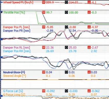
However, here are some notable exceptions to this. One is running on dirt and ice and the other is high-speed turns on aero cars where cornering drag is very significant. NASCAR, or equivalent, is a subset of this as well. That said, equation 13 is still a good approximation that will get you started.
steer angle (as shown in equation 14). Here we have wb as the wheelbase and R is the turn radius. However, the horse and buggy case is a subset of what we discussed in figure 3 and equations 1-11. Where you get into trouble is when you try and extend this when slip angles become a key factor.
As always, actual is coloured and simulated is black. If we look at the correlation in lateral and longitudinal g and steer angle, this backs up everything we have just discussed.
In part two next month we will take some of the concepts we have discussed here and give you some tools soyou can put this theory into practice yourself.
The other thing we need to discuss is the root cause of why the horse and buggy visualisations work. If we inspect figure 4, at low speeds the slip angles are negligible since the required forces are very small. We are talking one to two degrees. In this case, the steer angle will match up with the geometric arcs of a turn. That is a by product of looking at equation 10. In this case, the steer angle can be measured by the neutral
The proof is in the pudding, they say, and the correlation in figure 5 speaks volumes. As always, actual is coloured and simulated is black. If we look at the correlation in lateral and longitudinal g and steer angle, this backs up everything we have just discussed.
In part two, we will take some of the concepts here and give you the tools to put this theory into practice yourself.
Fig 5: Supercar correlation on a street course








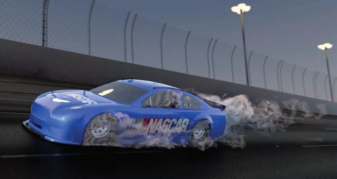







The World Touring Car Cup will undergo a change in format for next year, with the focus switching from a bespoke series of races to points scored in existing championships counting towards an overall title.

The decision to make the change and cancel a traditional world championship calendar has come about due to its failure to introduce 100 per cent sustainable fuel, which was a cornerstone of the series, according to the promoter, Discovery Sporting Events (DSE).
Despite confirming its longterm association with the WTCR in 2021, DSE has instead terminated its support for 2023, citing the fuel issue as the main reason behind its decision, and switched its allegiance to the electric Touring Car (ETCR) regulation set instead.
‘When we announced the extension of our long-term partnership with the FIA to promote the WTCR… we did so with the aim of making WTCR even more environmentally sustainable as part of our road map to deliver more sustainable motorsport,’ said former WTCC promoter and now head of DSE, Francois Ribeiro.
‘The introduction of 100 per cent sustainable fuel was central to this. Unfortunately, it has become apparent that such a fuel is not yet compatible with the production engines used in the WTCR category because it puts too great a demand on mechanical components.
‘With more and more corporate sponsors not wishing to be associated with a category that does not use fossil-free fuel, we have very real concerns that this will have a negative impact on WTCR grid numbers next season, which have already been compromised by the global health
pandemic, the war in Ukraine and a weakened economic outlook.’
The new TCR World Tour will be made up of nine events selected from various TCR-sanctioned series worldwide. Drivers competing in the World Tour will be awarded ranking points at a greater level than regular competitors in the races that are staged on four continents.
Leading drivers will then be invited to compete in a TCR World Ranking final, with Macau in November next year looking likely to be the location.
‘Since the inception of the TCR concept, WSC has built a large community of competitors,’ said WSC president, Marcello Lotti. ‘We are confident the TCR World Ranking, through the TCR World Tour and the TCR World Ranking Final, will give teams and drivers the opportunity to keep on competing at a global level.’
The World Sporting Council says its solution to the energy crisis and sustainability is to develop its own hybrid system that is available to any series that asks for it. ‘We believe this is the most logical answer to the trend of the market,’ confirms Lotti.
The FIA, meanwhile, which is following its own sustainability programme, supports the new format for the WTCC but says it still needs further investigation.
‘There is a need to identify and assess what is the best and most sustainable future for top-flight Touring Car racing as part of the FIA portfolio,’ said FIA Touring Car Commission president, Alan Gow. ‘Our goal would be to maintain a world title for conventionallypowered Touring Cars and ensure the competition is strong and prestigious.
‘Throughout its history, world Touring Car racing has used different formats, with titles decided either through a series or at a single event. Currently, we are considering all the possibilities, with the priority of ensuring any competition has a stable base on which to thrive for its long-term future.
‘With TCR, we have a proven set of technical regulations, with a variety of automotive brands represented and more than 1000 cars racing worldwide. Therefore, the intention would be to continue with this platform going forward.’
The WTCR has suffered a series of setbacks this year, with tyre failures leading to the cancellation of a key support race at the Nürburgring 24 hours, defending champions, Lynk & Co, withdrawing part-way through the year, and cancelled races leading to a reduction in grid numbers for those that did survive.
The all-female race series ended its 2022 season early so the organising body can focus on raising money for next year’s series. Expected funding from a contracted investment failed to materialise at the Marina Bay circuit in Singapore, forcing the organisers to rethink the tail end of the series.
The decision means Jamie Chadwick has claimed her third title.
‘It’s with great sadness and frustration that we announce our much-anticipated final three races of the 2022 season… will not go ahead,’ said series CEO, Catherine Bond Muir.
Acura, BMW and Cadillac stayed on after the final round of the WeatherTech Sportscar series at Road Atlanta to complete two days of testing with the new GTP cars that will compete in the Daytona 24 hours in January.

The only manufacturer missing was Porsche, which was sending its car through the Windshear wind tunnel as part of its performance balancing checks. Porsche did take to the track later in the month, to complete a 36-hour test at Sebring in a bid to make the cars reliable enough to complete a 24-hour race.
The FIA has teamed with Cranfield University in the UK to create the first ever FIA motorsport engineering scholarship. This is a unique global talent search initiative, which aims to provide a pathway for a talented young engineer from one of the FIA regions to obtain a Masters in Advanced Motorsport Engineering.
All the FIA’s member clubs in 146 countries, and their local
academic partners, will be given the opportunity to have their students participate in the selection process for the scholarship, which will cover both cost of tuition and living expenses in the UK.
Cranfield has undertaken research, consultancy and testing for the motorsport sector since the 1970s.
It is home to the FIA-approved Cranfield Impact Centre and AXSIM,
which work with Formula 1 and leading motorsport companies.
‘At the highest levels of motorsport there are still barriers to entry for the brightest engineers, with fierce competition for roles,’ says James Brighton, professor of automotive engineering at Cranfield. ‘Engineers need to have a passion for the sport, exceptional technical knowledge and the
ability to work in a fast-paced, high-pressure environment.
‘This scholarship will allow a student that typically would not be able to join us the chance to study on our postgraduate programme.’
Applications are open until 15February 2023 and can be accessed on the university website: www.cranfield.ac.uk/courses/ taught/ advanced-motorsport-engineering


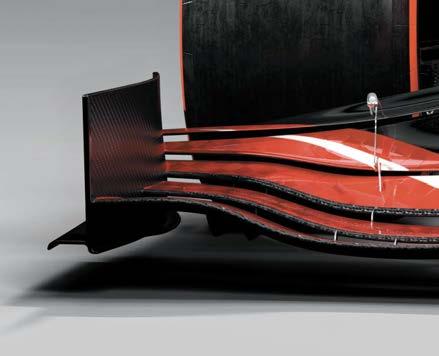
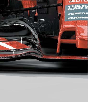


The opening line of Kipling’s famous poem seems currently relevant.
Unexpected, confusing, fascinating and full of opportunities – has there ever been such a curious time for business?
Recent discussions with the motorsport engineering community in the UK and USA show most are doing well. MIA members report substantially increased revenues over the past few years and constant and growing demand.
It’s true, extraordinary supply issues and cost increases beset all businesses, affecting efficiency, profitability and financial planning. But if demand is strong, and customer pressure maintained, all involved will find acceptable solutions.
‘Right time, right crowd, right content and the right price – free!’ was just one of many positive comments made online after the MIA’s CTS 2022 Show closed. Clearly, the motorsport business community really enjoyed and valued getting together in October to re-establish connections and make new ones.
Before hectic 2023 manufacturing and delivery schedules start, the show was just what the high-quality business audience, from the UK, USA and Europe, wanted. Buyers from F1 teams are a rare sight at trade shows but were there, along with those from rally and endurance racing, their confidence reflecting the continuing strength of demand.
I visited every exhibitor before the show closed, and only one was disappointed. The rest said the quality of delegates, location and timing were right on target. And backing that up, the majority of stands have been re-booked, even enlarged, for next October’s CTS23 show.
One factor behind the current high demand is the popularity of TV sports entertainment, which exploded during Covid. Millions of new people of all ages, genders and countries were hooked, and many of these new ‘eyeballs’ have stayed, bringing more sponsorship to the teams and suppliers.
Formula 1 and NASCAR are just two series that have increased revenues and are expanding
rapidly into new international markets. NASCAR entering a car at Le Mans will bring yet more global attention to the ‘brand’.
At last, motorsport is fully embracing the entertainment business, an unfulfilled promise over many years. This demand for entertaining competition on track, combined with endless new regulations, drives demand for more supplies.
But there is another factor that has increased demand. The commitment to reduce carbon emissions, which correctly has global support.
Many governments have announced the imminent end of the internal combustion engine. Personally, I believe this overly simplified,
These should help prove, or disprove, the suitability of hydrogen, sustainable fuels, hybrids and so on. Outcomes will be demonstrated faster than from the slower moving automotive or transport industry.
Demand is also growing fast from aerospace, marine and defence. They know our ‘challenge-led’ industry will test, develop and deliver good solutions quickly. Racebred, winning solutions are always the result of successful, innovative collaboration being delivered at pace and on time.
This exciting growth in demand is why CTS 2022 was created by the MIA members at this important time. A trade show, free of charge, to potential customers and partners,
They knew a show, focused on technology and engineering from motorsport competition, would attract buyers, investors, and partners from many sectors and countries.
Research showed October to be the right month. Well before the next motorsport season, a time when minds can be more open to new business and developments.
Walking the CTS Show, I saw first hand just how dynamic, positive and well-motivated people in motorsport are, even during difficult times.
blanket ban – always a vote winner – will steadily be eroded country by country, consumer by consumer, as realistic barriers emerge.
Cars and motorbikes are only a small part of the global emissions problem. Motorsport, held primarily on private land over limited distances, is an even smaller part of this sub set.
‘Competition drives innovation’ has never been more relevant. Our community has reacted fast and positively to the demand to develop and promote a multiplicity of powertrain solutions. Our vast new global motorsport audience will be highly influential as actual car buyers witness the performance of these new alternatives.
Already, part of the substantial motorsport R&D expenditure is being directed towards development of high-performance solutions.
In the grand scheme, global motorsport is a relatively small business community relying on extensive collaboration. Indeed, working together to resolve a difficulty with the FIA was the reason this community created the MIA in the first place and still own it today.

It is the UK’s good fortune that these people came together and created the Motorsport Valley business cluster. Now home to an international business community supplying advanced technology to the extremely competitive world of motorsport engineering.
For more information on the MIA, check out www.the-mia.com, or make contact directly via info@the-mia.com. Alternatively, if you wish to speak to me directly, just email chris.aylett@the-mia.com
‘If you can keep your head when all about you are losing theirs…’
There were many moments of controversy during the Japanese Grand Prix, such as the decision to delay the start due to wet weather, or the penalty that was applied to Charles Leclerc in the final throes of the race that guaranteed Max Verstappen the Drivers’ Championship title.
But perhaps the most obvious was that of Pierre Gasly and the tractor. Certainly, it was the most emotive, and for good reason after what happened to Jules Bianchi, but here I feel I need to stand up for race director, Eduardo Freitas. He has taken the blame (and brunt of punishment) for sending a recovery vehicle onto the track when there was still a car travelling at speed. The incident may well even cost him his job in Formula 1. He wouldn’t deserve that.
There was a thorough investigation into the incident by the FIA. It found that Gasly passed Carlos Sainz’s stricken car at 189km/h, as he had time to make up having completed a slow in-lap while wearing an advertising board. While there is no doubt the tractor should not have been on the track at the same time as a speeding Formula 1 car, which incidentally picked up a penalty for travelling at 250km/h under red flag conditions, Gasly was well aware that a recovery was taking place and should have driven at an appropriate speed past it. Formula 1 is supposed to be setting a high standard of driving, and I think Gasly’s standard was woefully low.
The Frenchman knew there was an accident at as, inadvertently, he had been caught up in it, which is why he had to pit for a new nose. The fact that Carlos Sainz, who had crashed into the barrier, was out of the car and safely the other side of it by the time the Alpha Tauri rounded the corner after its pit stop is not relevant. Sainz could have still been in the car, being tended by the medical team.

For Gasly to be surprised that the car was being recovered by a tractor is not a valid argument. He already knew where the accident was, and he has team radio so the pit wall could, or maybe did, warn him of a recovery vehicle on track.
Key to this whole sorry affair is not that there was a tractor on the track, it’s that there were marshals on track. I have written before that I believe drivers need to have more respect for the yellow flags, and in this instance it was clear to me that there was not enough regard for a double waved yellow, or even a red flag, by the time Gasly came upon
the scene. He said, incredibly, that he was nine seconds under his delta lap time and could have gone faster. What nonsense is this? Marshals were clearly signalling him to slow, and yet he said he had done everything correctly. He subsequently admitted to the stewards that he should have slowed, but that was only after lives were put at risk.
He said that having a tractor on the track was disrespectful to the family of Jules Bianchi, who in 2014 crashed into a recovery vehicle and subsquently died from his injuries. Gasly is correct, but he also needs to understand that around the whole track, under red flag conditions, he showed little respect for the marshals or volunteers and was instead focusing on his own lap time.
He said had he aquaplaned and hit the tractor he might have died. He missed the point that had he aquaplaned, he might have killed the marshals. That, then, leads to the question, should the marshals have been out on track at all? Maybe each race should be red flagged when there’s a need to send a person out on course. But why, if these are some of the best drivers in the world, should that be a question?
I hope the investigation addresses the need to have drivers, particularly in F1, respect the flags, the marshals and the volunteers, and introduce more stringent penalties for those that don’t.
Freitas has been benched for the season, Gasly received a time penalty and points on his licence. This doesn’t seem right to me. F1 is becoming a business, and the finest of details can make a difference to the wallet. Circuits and procedures have been weaponised in a way they never were before, and the rules now need to be tighter to close any loopholes.
The problem with seeking such perfection, as football has found with the introduction of VAR to make every offside and goal decision beyond question, is that you spoil the essence of the sport. In this instance in Japan, there were multiple mistakes, but to put the lives of marshals on track in danger should not pass by with a weak penalty.
I think the FIA needs to push responsibility back to the teams and drivers and relieve the pressure on the race director. You cannot claim to be worried about safety when you drive so quickly under caution with volunteers out on track recovering a broken car or injured driver. The caution is there for a reason, and the drivers must respond to the flags and conditions, not their target delta lap time.
ANDREW COTTON Editor


