HYDROGEN Solid-state storage and an ambitious plan to attack Pikes Peak in 2026
Inside the world of modern motorsport technology

HYDROGEN Solid-state storage and an ambitious plan to attack Pikes Peak in 2026
Inside the world of modern motorsport technology
Preparing for the first Indy 500 with electric power
Formula E
How fast charging works and its strategic impact
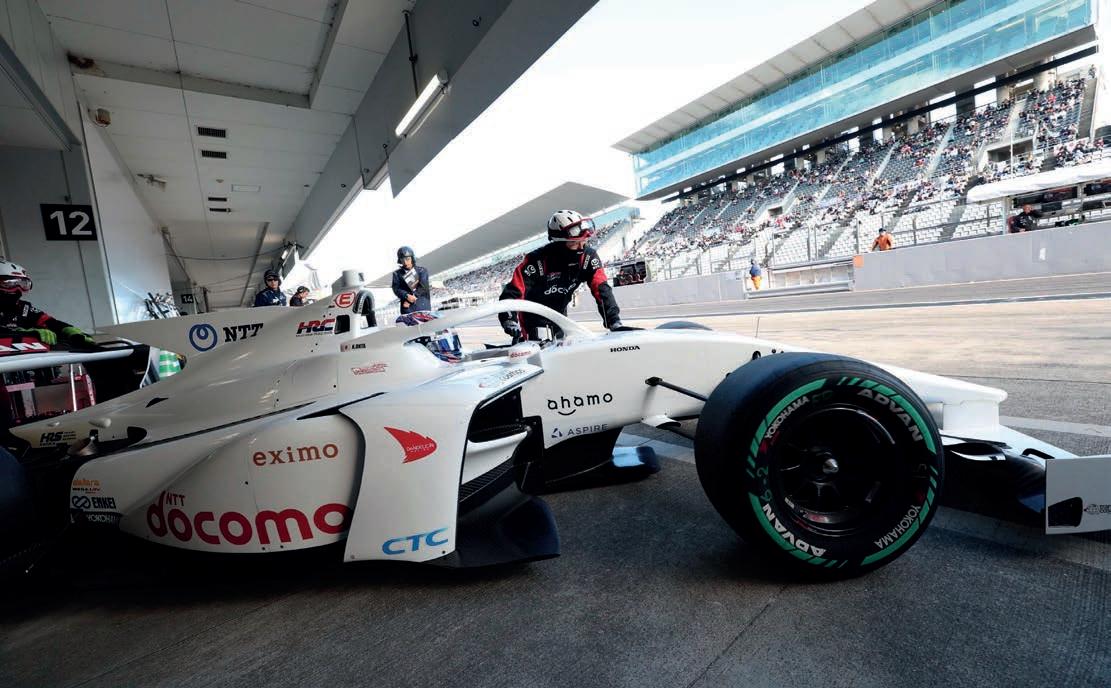
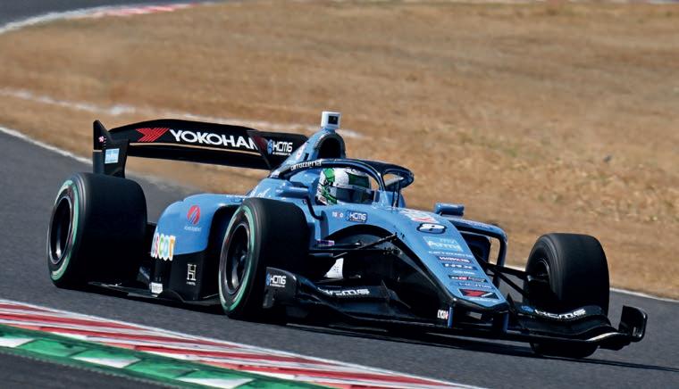
Super Formula
Teams get to grips with more sustainable tyre
ENGINEERING THE DRIVER
New earpiece sensor to monitor core temperature
ROBERT WICKENS
Bosch’s innovative hand control system explained
FUTURE OF LMP2
Fog begins to clear as tender details released


6 IndyCar race strategy
The lead up to the rst Indy 500 with hybrid power
5 Daniel Lloyd
38 The original R8
Charting the development of Audi’s rst Le Mans car
TECHNICAL
72 O -road safety
FIA’s rally raid seat attenuators
74 Danny Nowlan
Why the Nissan LMP1 car failed to meet its potential

First impressions of the new Formula E pit stop feature
FEATURES
12 Driver safety
Could a smart earpiece improve driver welfare?
18 Formula E
The technology enabling mid-race quick charging
24 Super Formula


Adapting to new generation sustainable tyres
30 Life Racing
We visit a control unit and wiring specialist
46 Torque sensors
Deep dive into how these important devices work
54 Hand controls
Bosch technology on Robert Wickens’ Corvette GT3
63 Solid state
An alternative, low-pressure solution to storing hydrogen
68 Tech update Turbos in the pipeline for LMP2

BUSINESS
78 News
FIA buys rallycross, WRC nds new fuel supplier and torque sensors for GT World Cup
82 Bump stop


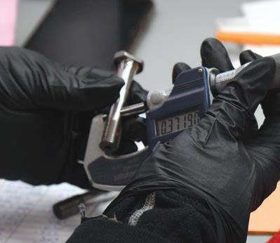
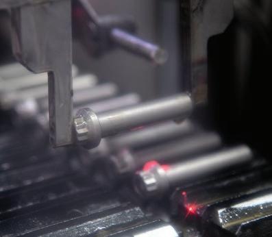
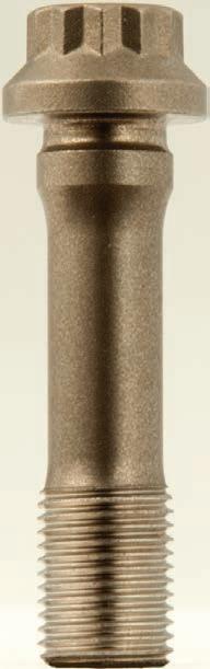
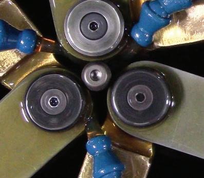

It takes as many as 25 steps to make an ARP rod bolt.
Each step is designed to ensure that the strength, toughness and fatigue resistance of the material is delivered in the final fastener.
ARP rod bolts are available for OE and aftermarket connecting rods in 5 strengths:
8740 Chrome Moly - 180-200,000 psi
ARP2000 - 220,000 psi
L19 - 260,000 psi
ARP3.5 - 260-280,000 psi
Custom Age 625+ - 260-280,000 psi

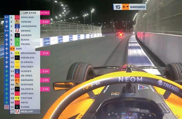
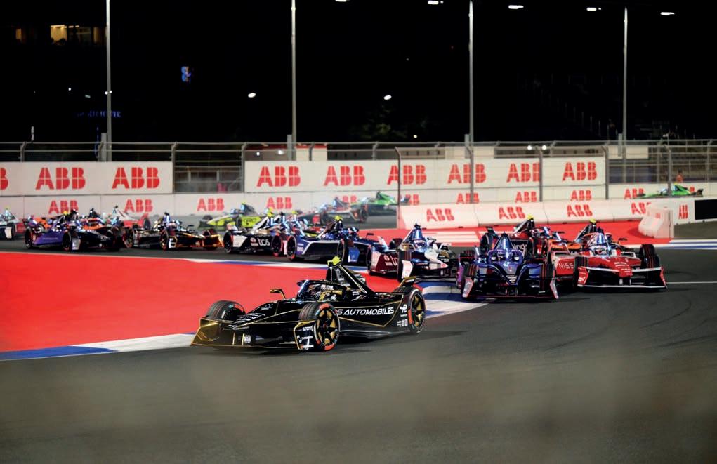
Pit stops returned to the FIA Formula E World Championship for the first time in nine seasons at last month’s Jeddah E-Prix. They require each car to take a 10 per cent energy top up from a 600kW fast charger. The race ended in spectacular fashion, as Maximilian Günther used his 0.1 per cent capacity advantage over an energy saving Oliver Rowland to capture victory at the final chicane. It was dream content for Formula E’s social media output but, for somebody watching at home like me, it was hard to grasp exactly what role the pit stops played in feeding that denouement. That’s not to say it was a disaster – crucially, there were no fast charging malfunctions – but there are some aspects I feel might benefit from being refined.
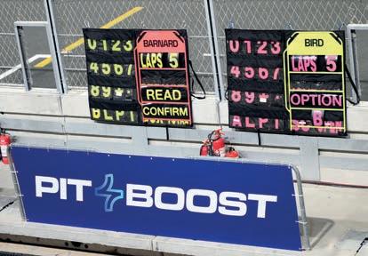
The first 31-lap race in Jeddah certainly didn’t lack drama. It started with a bang, ruining a few drivers’ evenings early doors, before settling into a steady rhythm. On lap nine, Rowland had enough of Günther’s energy saving and seized the lead. This prompted some drivers to take their first of two 50kW Attack Mode boosts, swiftly followed by a burst of pit stops once each car’s State of Charge (SoC) dipped below 60 per cent.
Things were confusing for a few minutes as the cars stopped for a 3.85kWh battery capacity top up. Although the stops were of equal duration, there were some changes in the order: those who pitted earliest benefited from exiting onto a clear track, which allowed them to run quicker and gain positions. However, they were reeled in over the closing laps by drivers such as Günther who, despite losing ground, had slightly more energy to play with.
In the moment, the TV timing screen was a kaleidoscope of colour-changing stickers. Considering the race lasted under 45 minutes, this all felt a bit overwhelming. You just didn’t know where to look.
Formula E touts it as a way of showing what fast charging technology can do. This is an important message for persuading more people to use EVs on the road. However, the series does not use Pit Boost as a range extender, which is exactly how everyday drivers would utilise it. Imagine the situation: you’re on a six-hour slog up the M6 to visit family and your car’s battery starts running low. You want to reach your destination before dinner, so a short, quick top up of energy is what you’re after. If you can reach your family without charging the battery you started with, you don’t need to stop the car. That’s what people want in an EV.
This is why Formula E’s approach of having Pit Boost races that are the same length as non-
than the pit stop race, which also had a brief safety car interlude. As a viewer, I’m not sure how impoprtant those 50 seconds of my life are. I might be able to make a cup of tea. By contrast, it would be more noticeable how Pit Boost impacts the cars if one race was lengthened. This would be a clearer, more roadrelevant way of showing this impressive piece of technology. It would also retain the unique excitement of the energy-saving Formula E race strategy that has produced many excellent finishes in recent years. It’s surely worth a try.
It wasn’t as simple as one driver just falling back though. Drivers taking their Attack Modes on slightly different laps, in and around the pit window, made it almost impossible to understand where the gain and loss occurred.
Pit Boost races doesn’t fully add up. I see what the championship is trying to do – it wants us to notice that teams can push harder when given 10 per cent more energy – but that’s hard for the TV viewer to see, especially with two bouts of Attack Mode also going on.
Squeezing that into an existing E-Prix race length of around 45 minutes has only made it more intricate to follow. The non-pit stop race in Jeddah was completed only 50 seconds quicker
The series previously had pit stops from 2014 to 2018. Then, drivers pitted because they had to as a Gen 1 car simply didn’t have enough charge to complete a race distance that befitted an international championship. Although ungainly, the method of a driver swapping their car for a new one was more in line with why motorsport has pit stops than the Pit Boost. For well over a century, pit stops have been done out of necessity: the need for more fuel, new tyres, and maybe (if you’re talking stock cars) a mechanic to bellyflop the bonnet back into place so a car can reach the finish. However, with Formula E, the Gen 3 Evo cars start with (just) enough energy to complete a race. That’s why, if I was in charge, I would ensure Pit Boost is taken out of a necessity that is organic, rather than rules enforced. Pit stops are traditionally underpinned by jeopardy and my suggestion to retain this important facet would be to increase the length of Pit Boost races, while allowing teams to take on varying levels of charge.
It will probably take a few more E-Prix to understand how Pit Boost feeds into Formula E race strategy but, if this reasonably proficient viewer of motorsport still struggles to understand how it has influenced a thrilling finale, maybe that will be a sign that its application needs a re-think.
If I was in charge, I would ensure Pit Boost is taken out of a necessity that is organic, rather than rules enforced
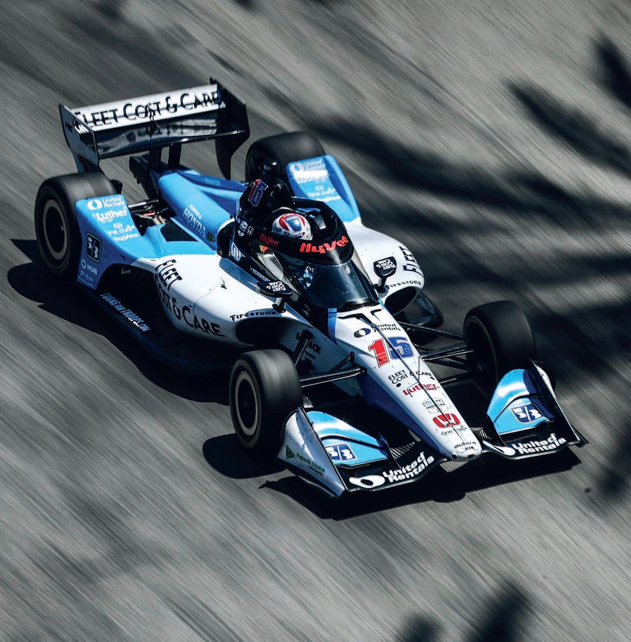
This year’s Indianapolis 500 will be the first run with hybrid technology. IndyCar engine chief, Darren Sansum, takes us through what to expect
By ANDREW COTTON
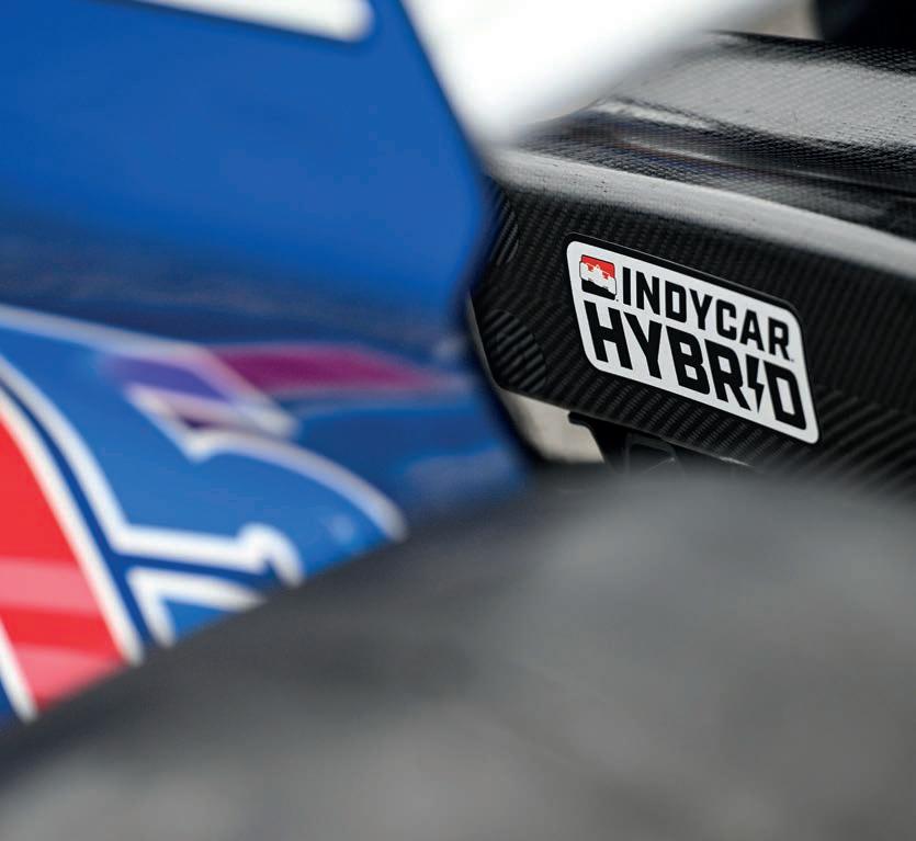
The 109th running of the Indianapolis 500 in May 2025 will be one of the most technically challenging yet, as teams get to grips with running a hybrid system at the race for the rst time. Hybrid technology was introduced to IndyCar midway through 2024 as part of the series’ move towards more relevant technology that suited its competing OEMs, Honda and Chevrolet. However, it only made its debut after the showpiece event, as the nal speci cation of the system was delayed due to a change of supplier.
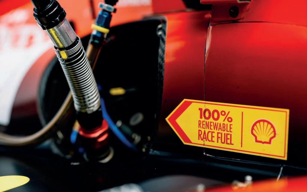
The hybrid system was originally due to arrive in 2022, alongside a new engine formula that would see capacity increased from 2.2-litres to 2.4, and the introduction of Shell’s 100 per cent renewable fuel, which reduced greenhouse gases by 60 per cent. The fuel was introduced in 2023 with very little fanfare, but a massive improvement in credentials for the series.
The new engine formula was then scrapped, due to higher projected costs for the teams, and the hybrid system was consequently delayed by two years, not helped by supply chain issues due to the Covid pandemic. Honda eventually took on most of the testing and development work for the new hybrid power unit, providing the supercapacitor pack, the DC-DC converter, the cooling system and the wiring. That all ensured the system was ready to be introduced at the Mid-Ohio race in July 2024. Now, after more than half a season running it, the organisation has acted to re ne the technology, with teams now facing the prospect of their rst Indy 500 using the upgraded hybrid architecture.
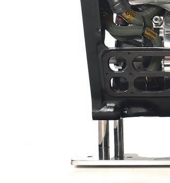
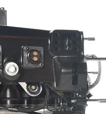
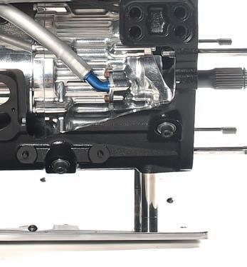
The hybrid system is mounted inside the Dallara-built bellhousing and uses a supercapacitor for fast charge and discharge cycles, and a motor generator unit (MGU) from Empel Systems. It’s a low voltage, 48V system to ensure it is safe to handle.
To t the system and stay within the weight limit of the car, Dallara had to take around 45kg out of the chassis as part of the integration process. That meant a lighter Aeroscreen, bellhousing and gearbox, all of which kept the overall weight of the car within safe, prescribed limits.
Since the hybrid system was introduced, it has encountered remarkably few problems, but it didn’t take long for the teams to call for an increase in power. Drivers complained that they only had a few seconds of electrical boost before the supercapacitor was drained, far from meeting, or even matching, their expectations based on experience in other series. Following a test at the tail end of 2024, IndyCar responded positively and, for the 2025 season, the duration of power delivery

been increased by more than 17 per cent, to 275kW per lap. This will be used in the Indy 500 for the rst time, and will bring power of the cars to 660bhp in race trim when electrical energy is deployed.
Teams will make strategic decisions on how to use the available hybrid power. In addition to two baseline settings, full open and full closed, Honda and Chevrolet have each homologated four settings for channelling the air ow through the radiators, so-called blockers, which are applied to the radiator intake. More blockers mean better aero, but higher engine temperatures.
Not long into the 2025 season, during round two at The Thermal Club in California, some teams fell foul of the new parameters. There was one issue of installation in the run up to the race, but several instances of the hybrid system shutting down due to overheating. Far from being worried about a similar issue occurring at the Indy 500, IndyCar engineers are con dent the teams will have learned how to use the blockers e ectively.
‘We talk about RMS current, which we’ve increased from a target of 400 to a target of 470, which is a 17 and a half per cent increase,’ says Darren Sansum, IndyCar’s managing director of engine development. ‘In doing so, we allow a maximum cooling temperature for
‘We allow a maximum cooling temperature for the hybrid system, but what we’re trying to protect is the supercapacitors’
Darren Sansum, IndyCar’s managing director of engine development
the hybrid system, but what we’re trying to protect is the supercapacitors. So, we put in a protection for the capacitor temperature because they are directly measured in the system that’s been designed by Honda.
‘We have that data live. We essentially implemented a derate of the system so, at 50degC, it starts to reduce the amount of throughput of energy so it can’t then continue to just overheat.
‘It starts at 50degC, and by 52.5degC it pretty much shuts itself o , so it’s quite a sharp shutdown. What happened at The Thermal Club is we mandated no backside blocker [for the radiators], but we did not control the front side blocker. Those parts are homologated by the manufacturers.
‘It’s a team decision on how they set that up, and a signi cant number of the cars decided to run blockers on the front and
didn’t have enough cooling, didn’t have enough air ow through their radiator and their hybrids ran into the derate. They then protected themselves and didn’t operate a hundred per cent of the energy.’
For the Indy 500, then, teams will have to make decisions on set-up, not only of the cars, but also of the air ow through the cooling system for the supercapacitors. Although the organisation does not believe the hybrid boost will be the race-deciding element, it could play as much a part as tyre choice and fuel strategy.
‘The front side blocker is very impactful at the speedway,’ explains Sansum. ‘So there’s quite a lot of motivation to run the front sidepod blocked o . Probably the teams will trade o hybrid cooling performance versus aero and make use of the thermal inertia of the system.
‘It’s the rst time with a new system and interaction, so it will be interesting to see the di erent approaches and which one is optimum. At a track like Thermal, the trade o is di erent. It’s not necessarily going to be a critical point, it’s just one of many factors, like the downforce they run, so it’s a race engineering decision.’
There will be no restriction on how drivers use the hybrid system in the race, so they will be free to regenerate and deploy when they like. Running in a slipstream, for example, will give a driver the chance to charge the battery, allowing for more boost when needed. It will certainly make for an interesting sprint to the chequered ag if that’s the pattern for this year’s race.
‘We’re running the same two levels of boost, so 1.3 bar in the race and 1.5 bar for qualifying,’ explains Sansum. ‘For the race, the hybrid regeneration portion will be load shifting. Basically, when you lift in the draft, it’ll charge the system a little bit and then, once you’ve got it charged, you can deploy it. So, if a driver is trying to make a pass in front, they can use that as a little bit of extra horsepower on one straight. It will make that pass easier to do. It could be the di erence for the win.’
There will be no restriction on how drivers use the hybrid system in the race, so they will be free to regenerate and deploy when they like
Rather than using the system to replace energy from the internal combustion engine, as in sportscars, which has led to complicated integration techniques, the installation has proven to be rather more straightforward in IndyCar. Although the series has increased the electrical power for 2025, it still believes there is more it can do under new regulations, due to be revealed soon and ready for introduction in 2027. ‘I think one clear direction is that we want a hybrid system, but one that is more impactful overall to the
current format, on both speedway and street courses,’ says Sansum. ‘Also, our goal is to have a new car for that time frame.’
Discussions are still ongoing as to the final specification of the car that will be introduced for 2027, and the power generated by the hybrid system. However, one thing is certain: IndyCar will continue to use a fuel from Shell with high sustainable content.
Shell’s involvement with IndyCar accelerated after Penske Corporation took over the series in 2020. Shell has sponsored Team Penske racecars for many years, so it was little surprise when the oil and gas multinational became the official fuel provider in 2023, replacing Speedway.
Penske’s main assignment for Shell was to develop a 100 per cent renewable race fuel without compromising engine performance. Shell duly launched a research project to investigate ways of replacing the petrol part of an E85 fuel blend. Such a blend is made up of 85 per cent ethanol and 15 per cent petrol, or other hydrocarbons.
The project found a suitable, unidentified renewable component, but this component produced fuel streams with an octane number (RON) of between 40 and 60, which was too low for a modern petrol racing engine. However, Shell determined the ethanol part of the E85 blend could compensate for this because, in its pure state, its octane rating is RON 109, while blended versions of ethanol can be even greater.
cent renewable fuel that also reduces greenhouse emissions
The final fuel’s performance was therefore largely influenced by the type of ethanol that was selected. Researchers settled on a second-generation ethanol derived from sugar cane waste, rather than a firstgeneration, crop-based ethanol. The product was sourced from Raízen, a Brazilian joint venture created in 2011 by a merger between Shell and Cosan. Brazil is one of the world’s largest producers and exporters of sugar.
The IndyCar team is satisfied that very few technical issues arose from the renewable fuel’s introduction, having provided Shell with the specification it required. The petroleum company delivered a fuel that meets the series’ demands and, it says, has reduced greenhouse gases by 40 per cent, compared with the previous IndyCar fuel, and 60 per cent compared with a baseline petrol from 20 years ago.
The previous IndyCar fuel was also E85, so there was only a relatively small change to the 15 per cent hydrocarbon content. There was no change to the additive packages from Shell,
The IndyCar team is satisfied that very few technical issues arose from the renewable fuel’s introduction [in 2023], having provided Shell with the specification it required
and the hydrocarbon element targeted the octane rating set by the series. Despite this success, IndyCar is looking to improve on the fuel’s credentials for 2027.
‘We haven’t discussed with Shell an iteration of the fuel as we strive for stability over this engine formula,’ says Sansum. ‘It’s a good question, whether or not there is something we can do that makes it makes that 60 per cent even better. It would be good if we could be fully carbon neutral.’
Unlike some other series, the IndyCar teams did not suffer the same problems with fuel dilution into the oil, a change to the brake specific fuel consumption or overall fuel consumption. ‘They gave us a candidate to test, and we sent some to both engine manufacturers and there was only a small change in the spark timing required. That was literally it,’ says Sansum. ‘The only slightly different thing was that we did have some cracking of the fuel fill hoses. We found that quite late in the day, but we changed the material and fixed that. We had to do some compatibility testing with the fuel cells, pumps and lines but, in terms of engine running, the feedback we had was that this was just a drop-in. Shell did a fantastic job.’
With renewable fuel that produces lower carbon emissions, a hybrid system to help improve overtaking opportunities and a new design of car on the very near horizon, IndyCar appears to have set out its stall pretty carefully.


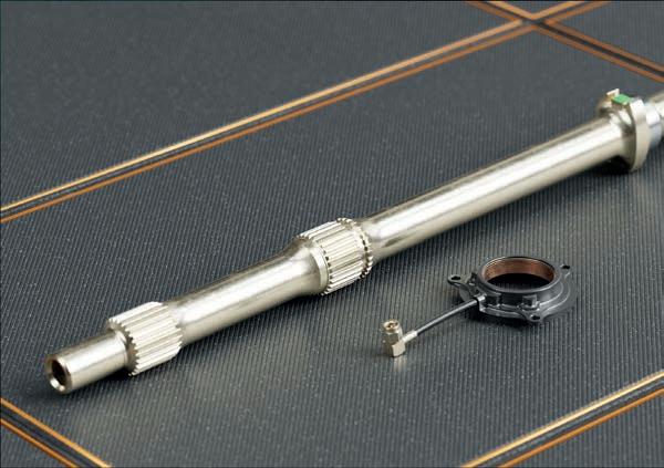

McLaren Applied and Transense Technologies have continuously advanced motorsport technology with their Surface Acoustic Wave (SAW) torque sensor technology for over a decade.


Unmatched performance: Deployed throughout IndyCar’s Balance of Performance (BoP) measurements, SAW torque sensors have demonstrated industry leading accuracy and consistency.
Innovative design: Surface acoustic waves enable direct torque measurement, replacing traditional strain gauges and significantly reducing error margins.
Durable and Wireless: Featuring a fully passive, wireless design, these sensors offer enhanced durability and simplify the system by eliminating active electronics.
High thermal and mechanical resilience: Engineered to perform reliably under extreme motorsport conditions, including high temperatures and vibrations.


For bespoke installations tailored to your needs contact us for a quotation.


Driver health and safety is the number one priority in modern motorsport, and drivers always need to keep cool, in more ways than one
IndyCar is conducting a study into how a smart earpiece that monitors driver core temperature can help improve safety and performance
By ANDREW COTTON, AIDAN DAVIS
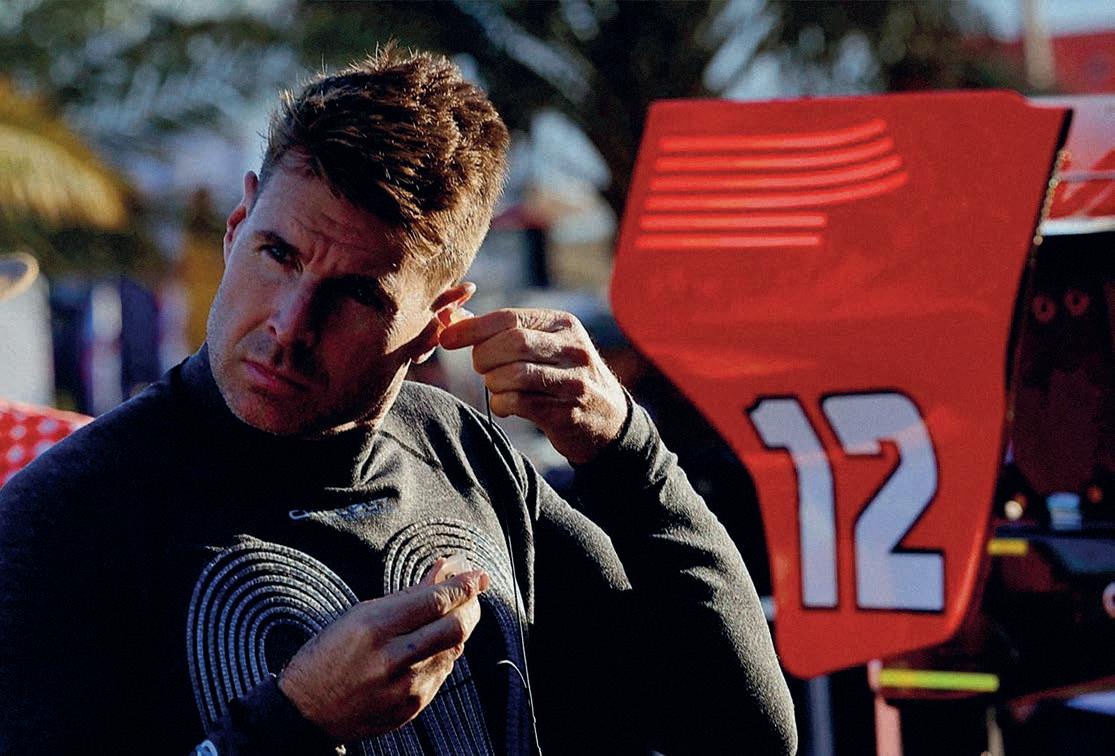
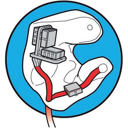
The quest to improve driver safety continues as IndyCar’s medical team has begun a programme to monitor driver core temperature during a race through thermometers embedded in the silicone earpieces commonly used by drivers. Since 2003, custom-fitted silicone earpieces have served multiple functions during IndyCar races, including cancelling out engine noise and carrying the radio receiver to enable driver communication with the pit. They have also been developed to include accelerometers that advise if a driver has experienced significant deceleration (during a crash, for example). In some cases, on the 2025 grid, such earpieces will carry an extra sensor to monitor core temperature, as part of the ongoing pursuit of enhanced safety.
The topic of driver cooling is a prevalent one. It was thrust into the spotlight at the 2023 Qatar Grand Prix when several Formula 1 drivers visibly struggled to cope with high temperatures. That led the FIA to add provisions for additional cooling equipment, such as a duct that allows air into the cockpit, and undershirts that circulate coolant around the torso to prevent core body temperatures escalating into dangerous territory.
For years, doctors and scientists have been monitoring driver condition in races, particularly endurance events, in order to improve recovery time, and therefore performance, when they return to the cockpit for another stint. Methods of cooling a driver down have improved dramatically from the old days of sticking their feet into a bucket of
icy water and slapping a cold towel on their forehead. Now, work is mainly focused on regulating core temperature, which is around 37degC in adults, although a couple of degrees either way can be enough to require medical attention. Recent studies have looked at doing this through intelligent neck braces and replenishing vital fluids using specially formulated drinks. They are currently being trialled in sportscar racing but have not yet been introduced to IndyCar.
As other series have sought to address their driver cooling concerns, so IndyCar is doing the same. The American championship linked with Michigan State University, which has long been studying driver wellbeing through
Methods of cooling a driver down have improved dramatically from the old days of sticking their feet into a bucket of icy water and slapping a cold towel on their forehead
its lead, Dr David Ferguson, to establish more effective monitoring of driver temperatures.
The latest strand of research places a thermometer into the earpiece, which is then hard wired into the electrical loom in the car. Information from this is fed back to an IndyCar truck that is already monitoring the car’s accident data recorder and collecting live car data, providing a real-time map of how the driver is faring in the cockpit.
‘About one third of our drivers have it right now, but the plan is for the full field to have it, probably by the end of the season,’ confirms Melissa McCarthy, an emergency physician on IndyCar’s AMR Safety medical team, who also serves as a safety engineering consultant to the series. ‘The intent is to be able to monitor in real time, but there are two things. One is, if we see that our drivers are at risk of experiencing any type of heat stress, such as heat exhaustion or heat stroke, we can notify the team manager so they can evaluate for any driver degradation. Secondly, if we know
‘Our main concern is if we’re getting to 39degC over an extended period of time, because that’s when you start seeing heat stroke-type symptoms, including brain damage’
Dr Melissa McCarthy, emergency physician on IndyCar’s AMR Safety team and safety engineering consultant to IndyCar
any of our drivers are under heat stress throughout a race, we can pay closer attention to them after the race for recovery.’
McCarthy is part of IndyCar’s own medical team that travels with the series from race to race. In doing so, she and her colleagues have detailed knowledge of each driver’s medical history and requirements, so are able to administer the best care when needed.
‘If we saw someone that was at risk from heat stroke, say, then we have paramedics in the pits, but we also have doctors on track, so they would go get that driver, probably bring them back to our mobile medical unit that we travel with,’ says McCarthy. ‘Then we would do the external cooling [with] ice packs on the neck, armpits, groin, and then cool mist. There are more invasive ways of doing it, but if we were that concerned, we would probably just take the driver to the hospital.’
Drivers are regularly exposed to elevated cockpit temperatures, high gravitational forces and cognitive loads while at the wheel. IndyCar does not use power steering, for example, which adds to a driver’s muscular e ort, or strain, and subsequently thermal load. The greatest stress placed on them is thermal strain, and this is backed up by scienti c research.
This strain is a result of drivers wearing an insulated, reproof racing suit while working in cockpits where temperatures regularly exceed 35degC. It is common for drivers’ core temperatures to exceed 38.5degC, and for them to lose two per cent of their body mass as sweat throughout the duration of a race.
These are regular situations. Extreme situations are where a driver’s core temperature may exceed 39.5degC and experience a loss of 3.5 per cent of body mass through sweating. A recent study showed that thermal strain leads to fatigue

in drivers, which impairs their ability to properly generate and modulate brake pressure, translating into a loss of on-track performance and increased driving errors. As such, there are safety and performance needs to observe the thermal strain on a driver over the course of a race, but also situations such as heat soak during a red ag.
‘The races we’re most worried about are August in Iowa and places like that, where they’re running on ovals and there’s not a lot of opportunities for cooling.’ are Obviously,
‘Say we’re running an oval, they come in to the pits for 10 minutes during a red ag,’ continues McCarthy. ‘Their core body temperature then goes up but, as soon as they go back out, it goes back down. Running our system in the background, we intend to have the ability to see how long their core body temperature is at that raised level.
‘Our main concern is if we’re getting to 39degC over an extended period of time, because that’s when you start seeing heat stroke-type symptoms, including brain damage. Obviously, we want to avoid that.


Core temperature monitoring in motorsport has previously relied on ingestible sensors, which provide accurate data but have some down sides. For example, the devices can interfere with MRI imaging in the event of an injury, making alternative, non-invasive solutions a necessity.
The thermal monitoring sensor continuously tracks core temperature via the tympanic membrane in the ear. It then transmits that data to race engineers and the medical team, enabling real-time physiological monitoring without disrupting the driver’s focus.
To validate its accuracy, a group of medical and PhD students at Michigan State’s Spartan Motorsports Performance Lab conducted a series of controlled tests comparing the ear sensor with the current ingestible sensor.
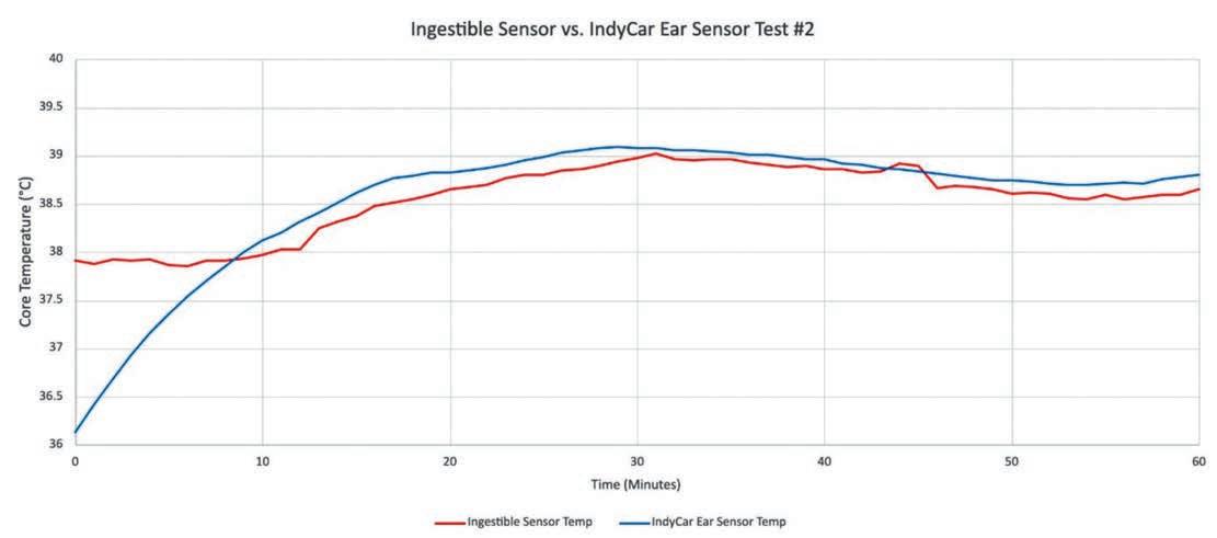
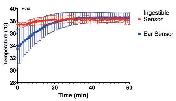
Seven trials were performed in a temperature-controlled environmental chamber, simulating conditions experienced in IndyCar races. The results demonstrated that the ear sensor provided reliable data. However, due to the unique custom silicone ear moulds, a 20–30-minute equilibration period was required before reaching stable and equivalent core temperature readings.
Initial analysis of the ear temperature sensor’s performance showed a moderate correlation (r = 0.56) with the ingestible sensor when considering all recorded data. However, further investigation revealed that the primary cause of this reduced correlation was the equilibration time of the ear sensor. Specifically, it required around 30 minutes to reach a core body temperature measurement comparable to the ingestible sensor.
‘As soon as you get [temperatures] over 38degC, maybe 38.5degC, you start to see a decline in [the physiological strain index],’ says Aidan Davis, one of the students at Michigan State who was part of the study.
By continuously monitoring core temperature, teams will be able to implement proactive cooling strategies, refine hydration protocols and optimise driver performance under extreme conditions
‘I went down to Indianapolis to have my ears moulded, and then they gave us an ADR [accident data recorder] system and the earpieces. We brought them back to Michigan State where we have a heat chamber, so we replicated the heat of an IndyCar cockpit. We had it at 95degF [35degC] and I was doing physical activity in the chamber. I was at a rate of about 150-160 beats per minute, which is representative of what you see while the drivers are racing.’
To better assess the sensor’s accuracy, the team excluded the first 30 minutes of data and re-ran the correlation analysis. The result was a near-perfect correlation (r = 0.99), demonstrating that once stabilised, the ear sensor provides accurate readings.
While a 30-minute warm-up period presents a challenge from scientific and clinical perspectives, its practical implications are minimal. For starters, overheating is unlikely to occur within the first 30 minutes of wearing the ear sensors, suggesting data from this time period could be disregarded. Future research will explore ways to reduce the equilibration time, or develop algorithms to compensate for initial deviations, while at the same time maintaining the sensor’s strong post-equilibration accuracy.
The introduction of the IndyCar Aeroscreen in 2023 was a change made for safety reasons, but there was a knock-on effect. The device reduced air entering the head area of the cockpit and gave the drivers a feeling that stagnant air around the helmet was increasing cockpit temperatures. New vents were therefore introduced to increase airflow into and out of the cockpit area.
IndyCar now has a scoop over the top of the Aeroscreen that can be used in hot races, and the series’ safety team hopes it will help drivers maintain a lower core temperature and therefore deliver a more consistent performance in a long, hot race.
‘We have the opportunity to change the different options for airflow through the cockpit, such as the scoop device that goes over the top of the Aeroscreen to blow air into the cockpit,’ adds McCarthy. ‘There have been occasions where we’ve mandated its use, in some extreme temperature weather. One of the things we want to look at when we get these sensors in is are we really making a difference? Are we making a difference in the driver’s perception of comfort, or are we changing core body temperature by altering the airflow in the car?’
The IndyCar Earpiece Sensor System represents another step forward in motorsport safety, providing a non-invasive, real-time method for tracking driver health. By continuously monitoring core temperature, teams will be able to implement proactive cooling strategies, refine hydration protocols and optimise driver performance under extreme conditions.
As the technology matures, its impact may well extend beyond IndyCar. With continued advancements, the integration of biometric monitoring tools such as heart rate variability and hydration levels could revolutionise driver safety and performance management.
In an era when precision and safety are paramount, the latest version of the IndyCar Earpiece Sensor System could set a new standard, ensuring drivers can safely push their limits while maintaining optimal physiological conditions.
This story is based on work undertaken by Michigan State University, Department of Kinesiology and College of Osteopathic Medicine by Aidan Davis, Abigail Faltus, Sara Xhaja, Gabriella Pluzsznynski and Dr David Ferguson PhD. And by IndyCar Medical Team / Safety and Engineering’s Dr Melissa McCarthy MD, Dr Julia Vaizer MD, Dr Terry Trammell MD, Taylor Prohaska and Vikkie Louks
The ultimate motorsport base layers. SFI/FIA-approved and packed with NASAdeveloped Outlast® technology, Walero base layers actively regulate your body temperature — keeping you cool, focused, and comfortable through every lap. Walero. Designed, tested and relied on by racing drivers. www.walero.uk • info@walero.uk


Formula E’s fast-charging pit stops finally made their debut in March. Racecar explores how the technology works
BY DANIEL LLOYD
The last time pit stops occurred in the FIA Formula E World Championship, drivers had to swap their energylimited cars mid-race to ensure they made the distance. Six seasons and 89 races later, pit stops are finally back, though this time drivers are spared the indignity of hopping between vehicles. Now, the emphasis is on quickly charging a single car, which opens new power deployment options. It is a feature brought in for reasons of road relevance, as fast charging continues to develop and mould our perceptions of what electric vehicles (EVs) are capable of. Formula E and the FIA want to showcase this technology through competition, using a system that is much more powerful than what is widely available. The so-called ‘Pit Boost’ made its debut at round three of the 2024 / ’25 season in Jeddah, Saudi Arabia, and will appear at five more E-Prix events this year.
Instead of being driven head on into the garage as they were in the past, the new Formula E pit stop involves cars pulling up conventionally in the direction of traffic. Once stationary, cars receive a boost of electrical energy from a 600kW charger. This adds 3.85kWh to the useable energy stored in the battery, known in Formula E circles as its State of Charge (SoC). The boost is worth 10 per cent of the full energy allowance for that race.
It is a feature brought in for reasons of road relevance, as fast charging continues to develop and mould our perceptions of what electric vehicles are capable of
In recent seasons, the starting SoC has varied depending on track characteristics but, in the 2024 / ’25 season, all cars are due to start all races with 38.5kWh available.
The introduction of fast charging to Formula E has been slow. The idea was first mooted back in 2019. Its usage was then ratified by the FIA World Motor Sport Council ahead of the 2022 / ’23 campaign, to coincide with the debut of the Gen3 chassis from Spark Racing Technology. Back then, it was known as ‘Attack Charge’. The plan was that the addition of energy through fast charging would unlock the ‘Attack Mode’ temporary power boost, which had been around since the Gen2 car arrived in 2018 / ’19. However, the system’s reliability took a long time to establish between its supplier, Fortescue Zero, and the FIA.
However, managing the heat produced by the booster, honing the communication between it and the car, and some cell supply challenges, created plenty of work.
While the focus was placed on launching the Gen3 car, the 2022-’23 and 2023-’24 seasons passed without Pit Boost seeing action in a race. During the latter campaign, testing became more public, as teams trialled Pit Boost during practice sessions on E-Prix weekends. Eventually, the championship and its supplier were satisfied that Pit Boost could debut in early 2025.
‘When the Gen3 project started, there was the idea of having this fast-charging capability,’ says Pablo Martino, head of Formula E at the FIA. ‘The FIA has worked really hard with Formula E and Fortescue Zero to develop from scratch and create this possibility. The system was developed in parallel at the beginning, together with the [Fortescue] battery. In any technical development project, especially when pushing the boundaries of technology, there are many challenges that need to be overcome, but we’ve managed to do so. In this case, we are talking about a technology that is still not on the road [at such power].’
Nurturing Formula E’s connection to the wider EV market has been central to keeping the project going, despite its delays. It not only helps maintain the interest of the eight car companies that race in the series, but also
‘The car is asking for how much energy it wants, and how quickly. The charger than has to deliver that, and adapt the voltage and current flow according to what’s being asked’
Tim Strafford, managing director of motorsport and chief innovation officer at Fortescue Zero
the existing, and potential, viewers who wish to know what EVs might do for them.
EV road charging is arranged into levels of complexity. Essentially, the energy output from the charger increases and the charging time decreases with every level. Level 1 provides little more than 2kWh of power through a standard 120V AC outlet and only gives a handful of miles per hour charged. Level 2 chargers are more potent, although the power is transferred in the same way as Level 1. Energy comes from the grid in alternating current (AC) and is converted on the car into direct current (DC) the battery can store and use. This takes time, but that time can be erased in Level 3 charging where the AC is turned to DC inside the charger. Currently, the fastest prevalent DC chargers run at a rate of 350kW. The Pit Booster in Formula E is just over 70 per cent
more powerful than that, although the automotive industry is catching up. Tesla is introducing 500kW chargers this year, while Chinese auto maker, BYD, recently unveiled a 1000kW (or 1MW) platform.
As one moves through the EV charging levels, the types of connectors required become increasingly complex. At Level 3, common types include Combine Charging System (CCS) and CHAdeMO. The Formula E system uses a CCS connector, similar to that found on road cars.
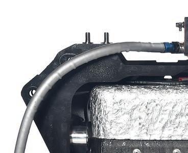
The boosters are transported in the championship’s communal freight, which includes the cars and other heavy equipment. They receive their energy from chargers made by ABB that give the cars their starting SoC at a gentler rate of 160kW. The electricity flows from the ABB unit into the Fortescue Zero fast charger in DC state. This is the correct current to be put into the RESS, but the voltage needs to be adjusted for the fast-charging function. A device called a DC-DC converter achieves this, and Fortescue has implemented its own for Pit Boost. Semiconductors and other advanced power electronics facilitate the conversion of power from low to high voltage, while minimising energy loss.
‘The car is asking for how much energy it wants, and how quickly,’ says Tim Strafford, managing director of motorsport and chief innovation officer at Fortescue Zero. ‘The charger then has to deliver that, and
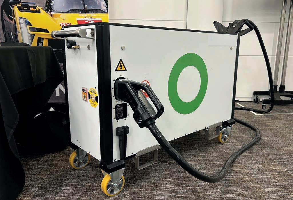
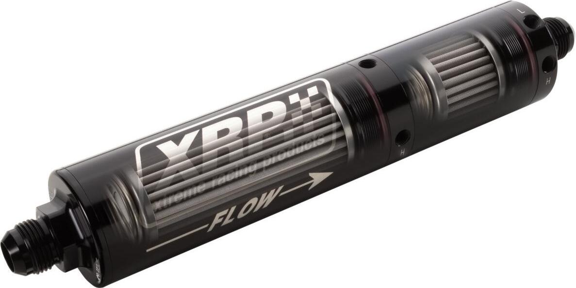
This is the Pit Booster. Its dimensions were largely dictated by those of the DC-DC converter. Fortescue’s Elysia battery intelligence software monitors the communication between charger and vehicle
adapt the voltage and current flow according to what’s being asked.
‘In fast charging, you have what’s called a power conversion layer. That is going from one voltage level, one current level – in this case, bridging the energy storage with the vehicle side. There is the potential to do a good job with efficiency, or a bad job. We have created a DC-to-DC converter that does that power conversion in a very efficient way. It means we’re able to optimise the whole system to avoid throwing energy away and avoid having more batteries on the system than we would otherwise need to counter the lost energy.’
Fortescue Zero is the innovation arm of the Australian Fortescue mining company that bought it from Williams in 2022. The parent company’s mining operations use massive electric trucks to move earth, while fast charging is used to keep them running.
‘In the mining application, we need to have DC-to-DC converters,’ adds Strafford. ‘The technology we’ve developed in motorsport bleeds into the mining application, both within the vehicle and the charging. The [mining] vehicles are autonomous, driving around all day so, when they’re plugged into a charger, they’re not doing useful work. That’s where fast charging comes in, because you can charge a mining truck in about half an hour. In that case, it’s actually 6MW. It’s an order of magnitude higher than what we do in Formula E, but the same technology scaled up.’
In the road car realm, a fast charger typically obtains its power from the grid or solar means. Electricity from the grid always comes in AC, so the charger needs an onboard converter to turn it into DC that the car’s battery can store. In Formula E, that conversion is done inside the ABB-supplied charger, before it reaches the Fortescue unit.
‘Fundamentally, it’s about unlocking bottlenecks in the system to achieve the sort of performance we’re looking for,’ explains Strafford. ‘One of the bottlenecks can be the grid. If you imagine a scenario in which all the Pit Boosts could be asked to operate at the same time, that’s 600kW times the number of cars pitting. The maths would draw to quite a sizeable number [potentially 13.2MW], which would be impossible to achieve with the electricity supply to the track.’
Fortescue Zero therefore briefly looked at using a single container to store the energy for Pit Boost, but settled on building a unit for each team, enough to charge both cars. It says the resulting unit is 860mm tall, 1378mm long, 446mm wide and weighs 316kg. The
‘It’s about unlocking bottlenecks in the system to achieve the sort of performance we’re looking for’
Tim Strafford
teams are responsible for the operation of their own unit during an E-Prix, but the FIA and Fortescue also bring their support staff. The supplier also has direct access via telemetry to monitor the system.
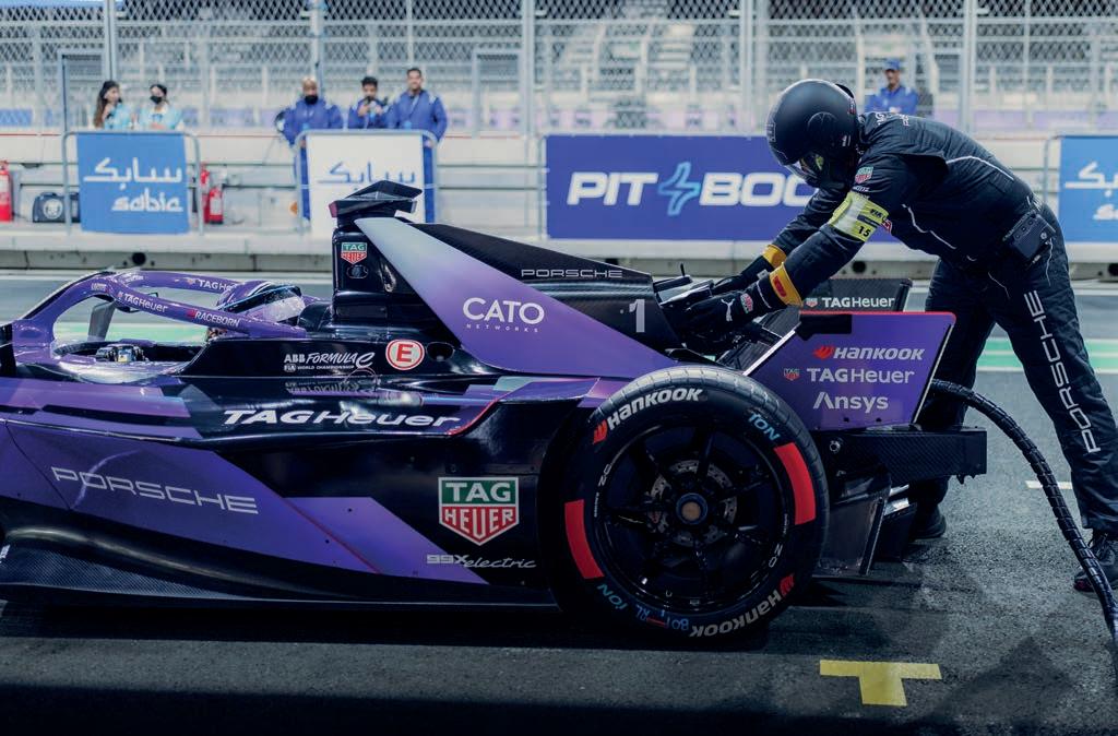
Every car must be stationary for 34 seconds during its pit stop. However, the amount of time the car boosts for is slightly less, about 30 seconds. Either side of that is a narrow buffer zone where the pressure is on.
‘The charging is quicker [than the standstill time], around 10 per cent,’ says Porsche’s director of factory motorsport in Formula E, Florian Modlinger. ‘That is a safety margin to make sure you have a bit of room for mistakes. The car needs to recognise the plug, and the software needs to accept the plug. If you put it a bit wrong, you immediately lose time.’’
To this, Albert Lau, chief engineer at the NEOM McLaren team, adds: ‘It’s right on the limit. You have to get everything right. The mechanics have to be on it. I think they’ve got those 34 seconds spot on, so there is still a sporting element.’
At 100 per cent efficiency, a 600kW charge for 30 seconds would add 5kWh to the battery’s SoC, but the Pit Boost only adds 3.85kWh. Full efficiency is simply not possible due to the heat losses that inevitably occur. The 30 seconds also includes the gradual ramp up and slowdown of the charge, while more time is taken up by communication
between the charger and the RESS, and the powertrain start-up procedure. This helps to explain why 5kWh is not added.
Also, Fortescue Zero and the FIA operate a so-called equity model within each car’s RESS, which sets the starting capacity for a race to ensure technical equity. The spec battery can hold over 40kWh, but the useable amount is 38.5kWh to account for variations that might limit a car’s performance.
‘There are going to be some losses,’ notes Lau. ‘There will be a ramp up of temperature you need to manage, so it’s never going to be always charging at 600kW and that’s it.’
A key problem to solve in development was speeding up the so-called ‘handshake’ between the RESS and the Pit Booster, which essentially pre-programs the flow of energy. This can take as long as a minute in road cars, but in Formula E is achieved in less than a second, enabling it to work in a race setting.
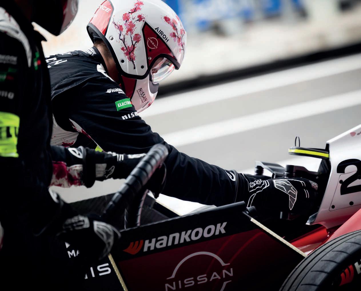
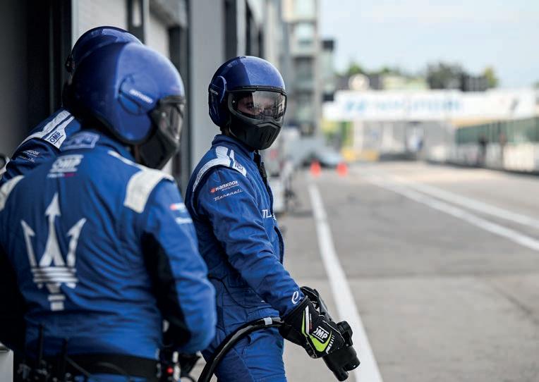
The new type of Formula E pit stop is less of a spectacle than others in racing, yet it’s also unique. You don’t have the intense choreography of a Formula 1 crew, the acrobatics of a Super Formula mechanic leaping over the nose, or the strength display of a NASCAR refueller. Instead, you have a mechanic who plugs the connector in, waits for the SoC to replenish by 10 per cent, and removes the connector. Nevertheless, it is the eye of the storm in an E-Prix and, ironically, where one of the biggest challenges lies.
At 100 per cent efficiency, a 600kW charge for 30 seconds would add 5kWh to the battery’s SoC, but the Pit Boost only adds 3.85kWh
‘The biggest challenges any team has encountered from the beginning of Season 11 up to now have been operational,’ suggests Martino. ‘The teams needed time to adapt and learn these processes. Some charges failed or were not completed, in [testing at] Jarama. The biggest challenge for them was the way the plug is connected onto the car. It has to be done in a precise manner; otherwise, if it’s done too hard or bent, the plug does not log, and the energy transfer does not happen. But the teams worked really hard to maximise and achieve perfection on the way they do this job. In Jeddah, all the Pit Boosts were completed without any troubles.’
When the teams arrived in Jeddah, they were curious to see how fast boosting would feed into the race strategy. While it is used on the road to increase a road car’s range capability, in Formula E it unlocks more performance from the Gen3 EVO car. For example, NEOM McLaren driver, Taylor Barnard, who scored two podiums in Jeddah, was on average
2.141s faster in the race with fast charging than the one without (taking his 20 best laps into account). It is no coincidence that both races in a double-header weekend have been kept the same length, despite one having a feature that gives each car 10 per cent more energy. How the teams deploy that additional energy is an interesting question, especially when they still have a pair of four-minute, 50kW Attack Mode boosts at their disposal.
‘That extra 10 per cent goes a long way to adding more performance,’ says Lau. ‘In a weird way, it reduces some of the overtaking. Your lift and coast periods become a little bit less because you’ve got more energy to deploy. How people want to save energy in the initial part, and deploy it later, becomes quite different. That will be dependent on the circuits you go to. In the pit stop race, drivers were driving to targets that made overtaking less possible. It was more of a flat-out race, whereas the non-pit stop race was a more traditional Gen3 EVO race.’
The return of pit stops also means in and out laps, and teams have been working hard on customising their powertrain running modes in a battle within Formula E’s intense theatre of software development.
‘How you want to regenerate and deploy that energy on an in or out lap, if you want to undercut or overcut a car, may be different,’ says Lau. ‘There is a different sequence you need to make in the software to give your drivers good cues. It just gives us another thing to think about and optimise.
‘Before, you would just start a lap and the only difference was if you were overtaking or not, or [energy] saving. It just adds more complexity to the technical challenge.’
Balancing when to use Attack Mode in relation to the pit stop introduces another strategic element. During Attack Mode, a car generates power from both its axles, rather than just the rear.
‘[The pit stop] gives the tyres a little bit of a breather, which is not a bad thing,’ notes Lau. ‘Depending on whether you come in on Attack Mode, and you’ve been pushing really hard because you want to use some extra energy before your pit stop, then maybe you’re stressing the rear axle less because you’re driving the front as well. It’s dependent on what kind of in lap you’re driving.’
In Jeddah, some teams benefited from using the pit stops to put their drivers in clean air. Maserati’s Jake Hughes was running in fourth position when everybody’s SoC went under 60 per cent. The Brit then had the honour of being the first driver to do a fast charge in Formula E competition. Hughes took Attack Mode on his out lap, and this combined with clean air to eat up the 1.2s deficit he had to Maximilian Günther before the stops. Hughes had risen to net second after the stops, although Günther ultimately charged past in the latter stages of the race, seizing victory with a final lap move on Oliver Rowland.
‘If a guy goes into the pits, you take the Attack Mode,’ suggests Modlinger. ‘You have a possibility to escape to open a gap. There are different strategies possible. If you have a battery temperature limited race, you can influence [strategy] by stopping earlier or later, because this has an effect on your battery temperature evolution.
‘You also need to consider the safety car. If it comes out in the pit window, it will have a massive effect if you have already pitted, or you still have to pit, on energy saving and losing track position. You need to consider all of these parameters.’
There are some strategic elements that didn’t manifest at Jeddah as much as they might at other venues. Considering it was built for F1, the Corniche Circuit has a
permanent pit building that gives drivers plenty of space to hit their marks.
‘Congested pit lanes will come into it where the pit lanes are a bit narrower than Jeddah,’ says Lau. ‘The SoC window is also going to come into play at some tracks. Maybe you hit that [60 per cent] level of SoC halfway around the lap, which isn’t a big deal as everyone can come in at the same time. But you might get to that point where it’s a little more marginal. You may have some teams – because they’ve used a little more energy in the first half of the race – who come in a lap earlier. There is a little bit of play you can do with that.’
In 2026, Formula E will introduce its Gen4 car, with an increased power output of 600kW and a 700kW regeneration capacity. If Pit Boost continues into that era, change will be afoot, because Podium Advanced Technologies is replacing Fortescue Zero as RESS supplier. Even if the Pit Boost unit is kept, calibration will be required between it and the vehicle.
‘The Gen4 battery will have a bigger power income capacity,’ says Martino, ‘so, of course, that can drift to a higher boost technology at some point. So far, all the exercises and development have been done following the status quo of the current technology. So, not trying to add any additional element. Gen4 development is ongoing. All the suppliers, especially the battery supplier, are already in the final stages of the technology’s development. The booster saw light [recently], so we feel that if there is [stability] in the technology for a couple of years, it’s not going to be problematic.’
Pit
Martino doesn’t think Pit Boost should be unfastened for the manufacturers to bring their own technology. Modlinger agrees, for the same reason that it would cost too much, even if it made pit stops more competitive. However, the FIA has said it wants to keep an open mind about how Pit Boost might evolve for the benefit of participants and viewers. It is early days, but this season will help to set the tone of future discussions on the subject.
‘It’s true that we have conversations [about] how we can introduce some kind of flexibility in terms of strategy for the teams when they are deploying the energy, that it can be transferred into less time in the pit but less energy in the battery,’ says Martino. ‘Like if you were refuelling your car, how many litres of fuel you would put in? This is not something that is decided yet, and is probably not going to happen in [2025 / ’26]. If it happens in [2026 / ’27], we are still discussing.’
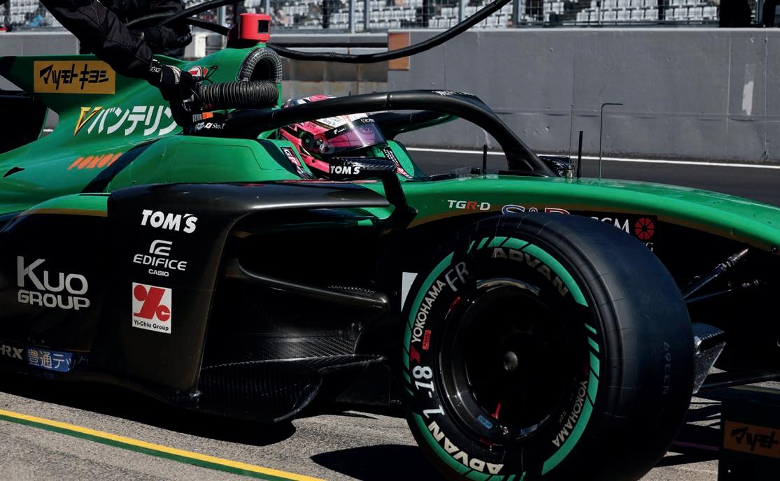
A new Super Formula season brings another new challenge, this time a tyre with even more sustainable material content
By JAMIE KLEIN
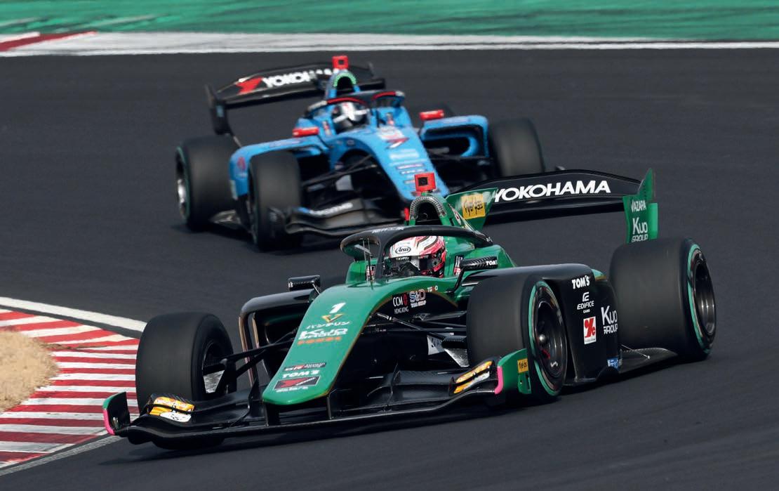
When the new Super Formula season kicked o in early March at Suzuka, the drivers and engineers were greeted with yet another new technical hurdle.
In 2023, it was the switch to the current aerodynamic package that saw the Dallarabuilt SF19 chassis re-named the SF23. Last year, it was the switch to common Öhlins corner dampers as the championship abandoned open damper development.
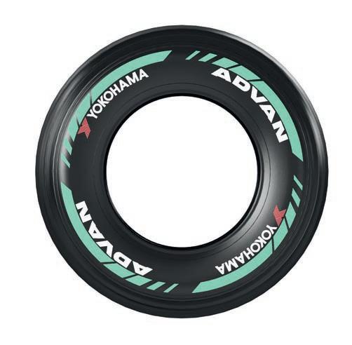
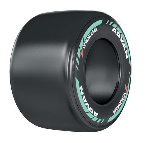
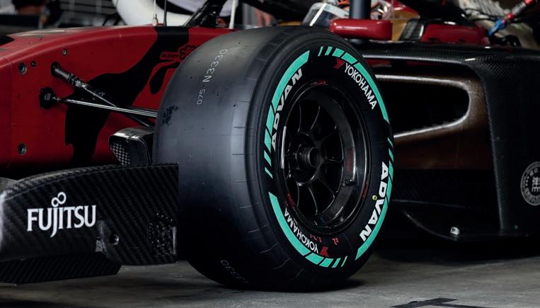
This year, the focus has shifted to the tyres, as sole supplier, Yokohama, has updated its o erings, speci cally by increasing the percentage of renewable materials used. When sustainable tyres were rst introduced to the series in 2023, the rubber featured 33 per cent sustainable content. That gure has gone up to 46 per cent for this season.
Championship promoter, JRP, is keen to highlight that this gure exceeds the 35 per cent gure originally targeted for 2025 in its ‘Next 50’ strategy. That was unveiled in 2022 as a roadmap for Super Formula’s evolution as it celebrated reaching the milestone of half a century (the series having been launched in 1973 as All-Japan Formula 2000).
‘Sustainable materials is something we had done a lot of research in, even before we decided to use them in our Super Formula tyres,’
says Yokohama technical manager, Eiji Saito.
‘It also happened to be something that aligned with JRP’s goals to create sustainable racing, and that’s how we got started, to show the world what can be possible.’
As for the materials used in the tyres, Saito explains: ‘We are using silica that is extracted using a scienti c method from rice husks, and we are using carbon powder, like soot. The most popular method is to use oil but, instead, we are using a di erent type of carbon.
‘As for the steel wires, the manufacturing process has been made carbon neutral. It’s not just that we are using renewable materials, but also the process itself has been changed to reduce CO2. We are also focused on making the factory’s operations more sustainable.’
‘We are using silica that is extracted using a scientific method from rice husks, and we are using carbon powder, like soot’
Eiji Saito, technical manager at Yokohama Tyres
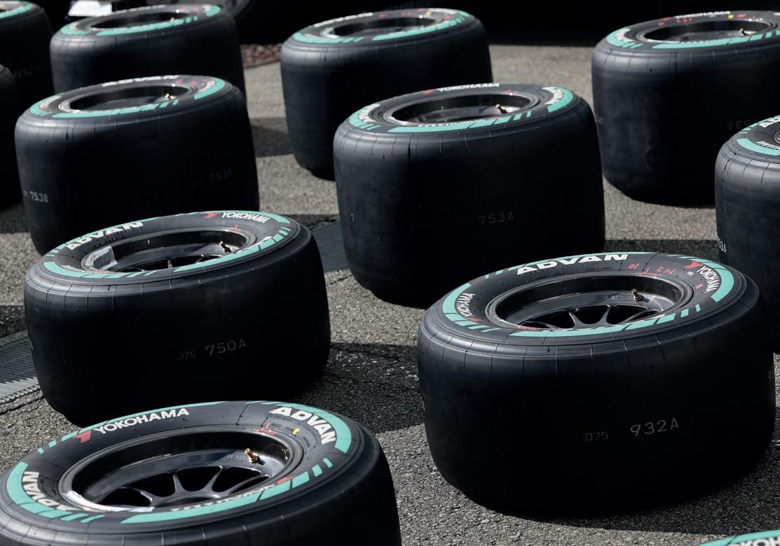
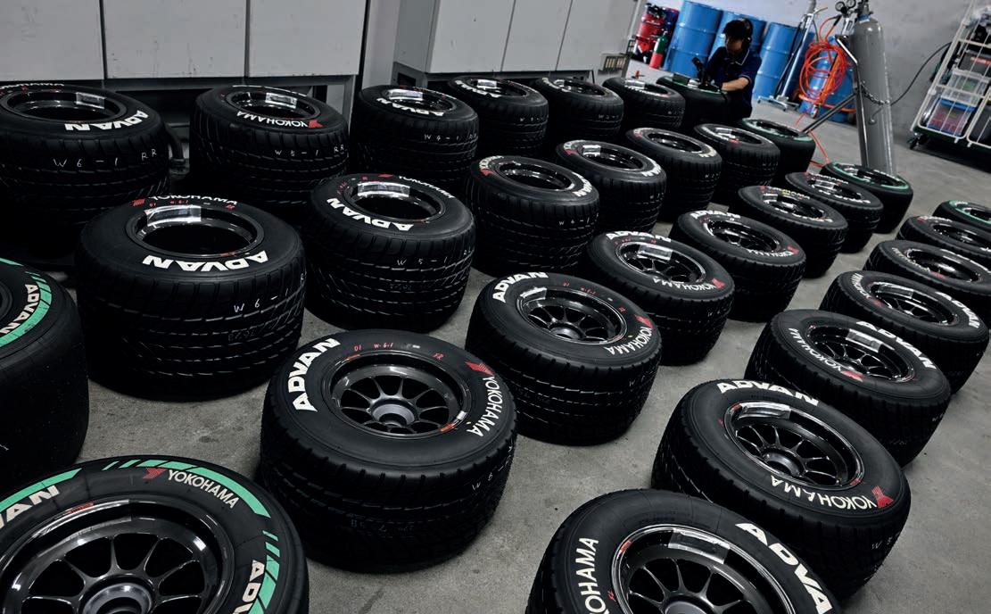
The new tyre’s introduction follows a year-long testing process with the two Super Formula development cars, a ectionately known as ‘Akatora’ (red tiger) and ‘Shirotora’ (white tiger), driven respectively by Mitsunori Takaboshi and Koudai Tsukakoshi. The 46 per cent tyre was selected from four options in an initial test at Motegi in late 2023, and then further re ned over the course of two further tests last year at Suzuka and Fuji.
However, it wasn’t until the pre-season test at Suzuka in February that the teams themselves had the opportunity to try out the new rubber, as the traditional post-season ‘rookie’ test in December took place on the outgoing 33 per cent tyre.
Heading into the current season, there were doubts whether the new tyre would live up to the high standard set by its predecessor, which earned plaudits for being consistent enough to allow drivers to push for long periods while also producing enough degradation to provide decent entertainment.
Performance-wise, the new tyre met expectations. While utilising a sti er construction, it also features a softer compound than the previous tyre, meaning there was no signi cant dip in lap times.
Indeed, at the Suzuka double-header, the quicker of the two pole times was a 1m36.060s. This was 0.271s slower than last year, with the difference probably accounted for by the fact that the 2024 Suzuka opener was bitterly cold, with a higher than normal downforce effect.
Ryan Dingle, who combines his main engineering job for Toyota in the FIA World Endurance Championship with an advisory role for the Rookie Racing squad in Super Formula, believes that when it comes to short-run performance with the new tyre, the main challenge is still controlling the surface temperature, but with an additional curveball thrown in the mix.
‘Being a Yokohama, controlling surface temperature still drives a lot of the conversation,’ says Dingle. ‘The new tyre is still quite susceptible to overheating on the surface and, when you do that, you lose performance on whichever axle is overheating for the next couple of corners. That’s one aspect that hasn’t changed.
‘The main difference is on the front axle, and how reactive the car is. It’s related to the sharpness of the steering. It makes it more difficult to set the car up so it is appropriate at entry but also not giving too much understeer at mid-corner.’
The bigger question mark was how the new tyre would perform over a long run, and whether it would degrade enough to make the races sufficiently entertaining. Fears in the
‘The new tyre is still quite susceptible to overheating on the surface… That’s one aspect that hasn’t changed’
Ryan Dingle, technical advisor for Rookie Racing in Super Formula
paddock of a dull weekend were compounded by the changes JRP has made to the race format this year, chief among them abolishing the pit window for Sunday races.
With Super Formula going from two double-headers on last year’s calendar to five this year, it was decided that something needed to be done to differentiate the Saturday and Sunday races. What JRP settled on was making the Saturday races shorter, equating to four laps at Suzuka, while abolishing the rule that forced drivers to serve their mandatory pit stops on, or after, lap 10, a rule that had been in place since 2019, but on Sundays only. Paradoxically, only the shorter Saturday races will keep the ‘lap 10’ rule.
With the pit window opening on lap one for the 31-lap Sunday race, this move had the potential to prompt a large number of drivers to pit at the very first opportunity. With the old spec of Yokohama, it would have required a certain amount of bravery to attempt a 30-lap stint, but it seemed a logical thing to try on the new tyre, particularly with
the new rubber proving somewhat tricky to switch on in cool conditions.
A lack of running in pre-season testing, which was impacted by snow, meant the entire field went into the opening practice session on Friday having little idea of how the new tyre would behave over a longer stint, and the two sessions that day didn’t provide much of a clue either. A poorly-timed red flag caused many drivers to abort long runs, with only Kondo Racing’s Kenta Yamashita cracking double digits with a 12-lap run in FP1.
Yamashita reported that evening that he had noticed his lap times getting faster, not slower, over those dozen laps as the fuel load went down.
Tadasuke Makino, one of the pre-season favourites for Dandelion Racing, predicted that with the tyres taking more than a full lap to warm up, 10 to 15 drivers would take a lap one pit stop, if nothing else to get the mandatory stop out of the way before the first set of tyres had fully warmed up.
In Super Formula, the pit lane stays open in the event of a safety car so, should there be a first-lap accident, the chances of seeing almost the whole field coming in to change tyres after a single lap were deemed high. Ironically, this is exactly what happened in the Saturday race, at a stroke eliminating all of the strategic intrigue of the race. On Sunday, however, there was no early
There were concerns from some of the teams over a lack of tyre degradation with the new rubber, but those appear to be unfounded, and early signs are that the tyres are consistent performers
safety car, and only five takers for an opening-lap pit stop. In fact, over half the field opted for a ‘stay out’ strategy, pitting between laps 12 and 21.
Nakajima Racing offered an interesting test case as it split its strategies between the two cars, with Igor Fraga stopping on lap two and team mate, Ren Sato, on lap 21. Sato’s pace after a slow stop was blistering, as he set the fastest lap of the race on his way to sixth behind Fraga, passing some of his rivals on older rubber with relative ease.
Nakajima Racing advisor, Hirohide Hamashima, best known for heading up Bridgestone’s F1 programme from 1997 until 2010, before later taking up a role at Ferrari, commented that he was impressed by the new Yokohama tyre’s consistency, while also noting degradation was not quite as non-existent as some had feared it might be prior to the race weekend.
‘Looking at our drivers, Sato, who went out on new tyres, was lapping the mid1m38s, while Fraga, who pitted early and used those tyres until the end, couldn’t go any faster than the low 1m39s on old tyres,’ noted Hamashima. ‘So, it seems there’s a difference of around a second between new tyres and ones that have been used for about 20 laps.’
On the decision to do away with the pit window for the Sunday race, Hamashima added: ‘I think it was interesting. It allowed people starting lower down to make more
progress than they might have done otherwise, and it allows teams to completely separate the strategies of their two drivers. Especially for those last 10 laps, when you have those that stayed out longer and those that stopped at the start coming together, I thought it was fascinating.’
Despite that, in Hamashima’s opinion, degradation at Suzuka was ‘a little on the low side. It would be better if there was a little more but, as you saw with Sato, if it’s possible to make that much progress [on fresh tyres], then it’s interesting enough.’
The question now is whether the trends seen at Suzuka will apply to other races on the calendar. That’s a difficult question to answer at such an early point in the season, given that temperatures during the opening race weekend generally stayed in the high single digits to low teens.
While he didn’t observe much degradation for Rookie Racing driver, Kazuya Oshima, Dingle believes the innate
‘It seems there’s a difference of around a second between new tyres and ones that have been used for about 20 laps’
Hirohide Hamashima, advisor to Nakajima Racing
characteristics of the Yokohama rubber mean degradation will inevitably become a more significant factor later in the year when temperatures rise: ‘When it’s hotter, we will have the issue of the surface overheating, but without the opportunity to cool it as much with the ambient temperature and, especially, the track temperature being higher.
‘I think we’ll see more overheating of the surface and more degradation. At Suzuka, it was never critical with the surface temperature.’
Dingle predicts that the third round of the season, held at Autopolis in late May, will be the first real acid test for the new tyres.
‘Autopolis is a very difficult circuit on tyres, especially for graining,’ he says. ‘A team with a good long run set-up, like Impul with Ryo Hirakawa a few years ago, could take advantage of that by pitting very late.’
At Suzuka, the same three teams that have monopolised the top step of the podium since 2023 – Mugen, TOM’S and Dandelion –proved the ones to beat again. Sato, third in the first race, was the only driver not from any of these teams to set foot on the podium.
Just as the change to common dampers last year looks to have done very little to change the fundamental pecking order, the same, at least for now, appears to apply to the tyre, despite pre-season predictions that a major re-shuffle could be on the cards.
‘The fundamental characteristics are unchanged; it’s still a Yokohama,’ adds Dingle. ‘You can go about your business the same as you did before. We saw Mugen still doing a very slow warm-up procedure [in qualifying], to build core temperature without overheating the surface, and then pushing in the last sector to get the surface temperature you need for turn one. This is the same playbook as before, and it still works.’
For now, then, Yokohama can draw satisfaction from having introduced a new tyre with limited testing that does what it is supposed to do. It now seems inevitable that the percentage of renewable materials in the company's tyres will increase in years to come.
Last year during a test at Fuji, a 60 per cent renewable tyre was used in a demonstration run carried out by JRP chairman, Masahiko Kondo, providing proof of how much further the concept can be pushed. ‘That is our goal, and we are developing with the aim of moving towards that goal,’ says Yokohama’s Saito. 'For now it’s still a prototype, and the performance is lower than that of a real racing tyre. The aim is to increase the percentage of sustainable materials, together with the performance. This year’s tyre is a middle step towards that goal.’
How much further than 60 per cent it is possible to go remains to be seen. Asked if a 100 per cent renewable tyre could be a
possibility in the future, Saito replies: ‘For a championship with this level of performance, that would be extremely difficult. But for road cars, we think it is achievable, and that’s something we are working towards.’
One further challenge Saito notes has faced Yokohama in its quest is a more fundamental one: ‘The means by which we can get our hands on these materials is still quite limited,’ admits Saito. ‘It’s enough to create racing tyres but, for road tyres, we don’t have enough of the materials to sell tyres in great volume, so that’s something we still need to do more research on.
‘The aim for the future is to increase the percentage of sustainable materials, together with the performance. This year’s tyre is a middle step towards that goal’
Eiji Saito
'The means by which we can get our hands on these [renewable] materials is still quite limited… so that's something we still need to do more research on'
Eiji Saito
‘The raw materials are not something we can create ourselves; it has to be bought from an external supplier. We are trying to support the supplier to expand their capacity, also because we are getting requests from other categories to use this kind of tyre.’
From Super Formula’s point of view, any positive PR coming from a more sustainable tyre would be worth nothing if the quality of the racing suffers, which is something JRP president, Yoshihisa Ueno, is keen to emphasise. ‘Performance and entertainment are also things we must consider, along with sustainability,' he says. 'We don’t want to
compromise one by increasing the other. So there’s no hurry to dramatically increase the percentage of sustainable materials.’
In any case, tyres are not the only measure JRP has taken to boost its environmental credentials. When the SF23 was introduced, flax fibre panels made by Bcomp were brought in, and the series has flirted with carbon-neutral fuel. However, despite tests with various suppliers, it is still running on regular fuel, unlike the Super GT series.
Currently, going down the renewable tyre path isn’t an option for Super GT while it has a tyre war, because the percentage of
sustainable materials used in a tyre is almost impossible for an outside scrutineer to verify. In other words, it would be too easy for a tyre maker to bend the rules, even if a regulatory minimum percentage was imposed.
That makes Super Formula, single-seater racing’s fastest series outside of Formula 1, the ideal platform for Yokohama to continue its pursuit of renewable tyre technology. But doing that, while maintaining the required level of performance, and ensuring the series remains one its legions of fans still want to watch, presents a considerable challenge for the Japanese tyre manufacturer.


Motorsport electronics need to be hi-tech, lightweight and close to indestructible. Life Racing explains how it balances these often contradictory requirements
By MIKE BRESLIN

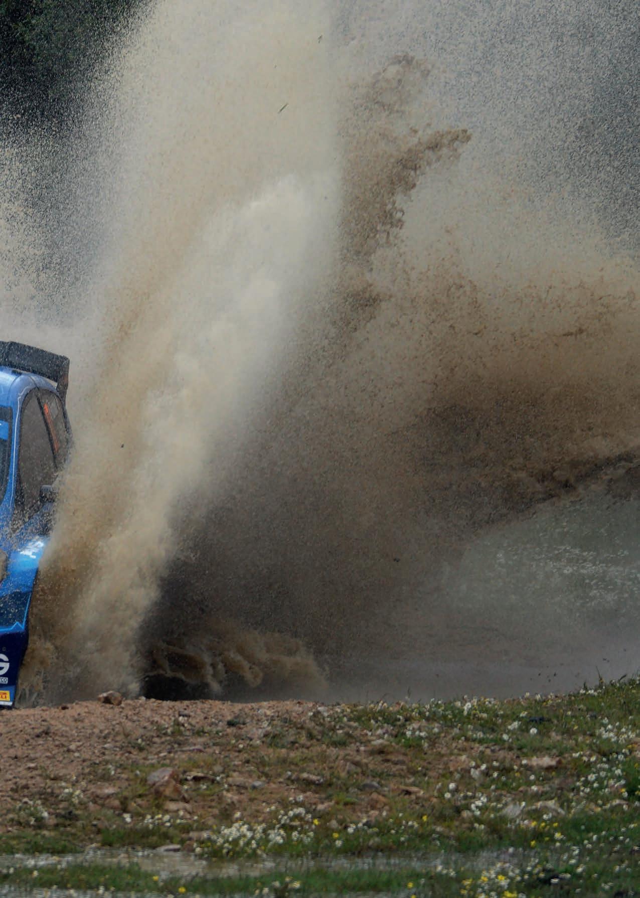
Life Racing supplies electronics to M-Sport’s Rally2 programme, among others, meaning its products are pushed to the very limit

Sometimes it’s tempting to compare a racecar to a human being. After all, it has four ‘limbs’, a body and a thumping heart, which we call an engine. But a person is nothing without a brain and, in a racecar context, this is where the grey matter of the little black box and the twisting nerves in the wiring harness come into play.
These electronic elements bring a modern racecar to life, and perhaps this was in Mike Lancaster’s mind when he named his then new venture, Life Racing, in 2002 –though he says he cannot recall how the name originated. What is for sure, though, is that Life has since become one of the UK’s most respected and successful motorsport electronics companies.


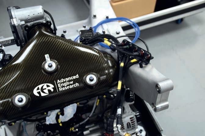
engine company that had that very DNA built into it because, at that time, a lot of engine companies were designing engines without the electronics in mind.
‘The electronics can work around problems, particularly knock control in those days, and better turbocharger control. AER has still got much better turbo control than everybody else, because we developed those things in concert with the engine.’
These days, while Life manufactures the whole gamut of motorsport electronics products, the bread and butter of the operation is the design and manufacture of what Andrew Saunders, senior engineer of technical sales, calls ‘black boxes’, by which he means components like ECUs and PDUs (power distribution units).
Indeed, Life’s products are now at the heart – or rather brain – of a wide selection of international and national-level competition vehicles, including Indy NXT, rally cars from M-Sport and Renault, Hyundai TCRs, Radicals and Revolutions, plus a growing number of high-end road cars.
Life Racing has also had a very successful involvement in top-level sportscars, largely through its connection with well-known engine builder, AER. The two companies operate out of the same sprawling base on an industrial estate in Basildon, Essex, and Lancaster is the managing director of both, yet they are entirely separate entities.


Life’s life story is a little complicated but, essentially, Lancaster co-founded another electronics company, Pectel Control Systems, and then, together with his partner in Pectel, set up AER. The pair then went their separate ways, Lancaster keeping the engine business, his partner the electronics side, supplying into AER. When Pectel was later bought by Pi Research, Lancaster found himself in a position where he needed to set up his own motorsport electronics rm.
There was a very good reason for this, as Lancaster explains: ‘One of the points of AER was that the engines were developed in concert with modern electronics. They were not engines where you apply the electronics after the fact. I thought we could start an
Saunders was originally an engine man. He worked for Ilmor and was there through its evolution into Mercedes-Benz HPP, before moving to AER and then transferring to Life around ve years ago. However, he is keen to point out that at Life the term ECU refers to far more than just ‘engine’ control units.
‘When people refer to an ECU, it can be an engine control unit or an electronic control unit,’ Saunders says. ‘I think it’s an electronic control unit, but I also think nowadays it would probably be better if it was called a powertrain control unit. If you designed a basic ECU to just run a four-cylinder engine, it would probably be half the size of our F88 [Life’s entry-level ECU] because it’s only got four injectors and four coils. That’s all it has to do. But our device has got 88 pins.
‘With our ECUs, as well as running the engine, we can run seamless sequential gearbox control, anti-lag control and there’s another part of the ECU that’s o controlling the wastegate. We’ve also got a very good traction control system. All of these systems sit within the same control unit. One of the reasons for this is that what most of those systems demand at some point is a change in engine torque behaviour.’

To give an example, Life’s high end F90F ECU can look after a wide range of powertrain tasks including turbocharging, supercharging, drive-by-wire, variable valve timing and VTEC, as well as the gearbox, di erential and many other functions on a racecar.
‘When people refer to an ECU, it can be an engine control unit or an electronic control unit… but nowadays it would probably be better if it was called a powertrain control unit’
Andrew Saunders, senior engineer of technical sales at Life Racing
‘Our core units do everything,’ Saunders adds. ‘In the old days, you might have an engine control unit, a gearbox control unit and a DRS control unit. Some companies still do it that way but, on most of the projects we oversee, we try to minimise boxes and drive everything effectively from one processor.’
Of course, these are hugely complicated pieces of equipment, so require a very structured design process, and this starts with an evaluation of exactly what is needed.
‘There’s a term we use a lot, which is ‘IO’; inputs and outputs,’ says Saunders. ‘A wheel speed sensor, for example, is an output and an input. You have to power it so it works, so that’s an output. Then, when it starts working, it sends you a signal, which is your input. The car is covered in outputs and inputs.
‘What we do to start with is write a list. The difficult bit is getting this information from the customer, because sometimes they haven’t decided what they want on their car at the point they’re ordering the system. We need a list of every device that’s going on the car, every sensor, every display panel, every motor, every pump, every light bulb.
‘Then we drill down into what type of input it is and what type of output it is, how much power it needs to power it and how frequently you need to sample the information coming from it. Then we build a structure, and decide if those devices are primarily engine and powertrain control devices, or if they’re primarily power vehicle control devices. We can then split them off and try and separate your engine control unit from your power distribution unit.’
Unsurprisingly, the most difficult part of the process is the coding. ‘The software is the biggest task, and it takes the longest time,’ confirms Lancaster, who designs many of the products that Life makes, while Mark Colby is in charge of coding. ‘The hardware itself is relatively quick to design and produce. To design that, we have to discuss emissions: radiated emissions, conducted emissions, the temperature, the way it has to work and how big the box is. There’s a lot that goes into deciding what you end up making, but a big part of that is up to the guys who do the coding. And that’s really difficult, the amount of coding there is. The people that can actually write embedded software in control units are very few and far between.’
When it comes to the boxes themselves, the cases for the company’s higher end products are machined from solid aluminium, while those for the likes of the entry-level F88 are cast aluminium. Inside these boxes sit small PCBs made up of many layers of etched copper circuitry interspersed with layers of
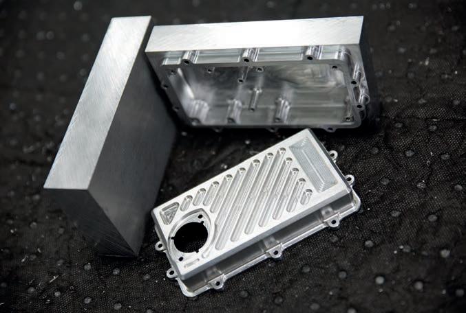
insulation (16 layers for the F88) and then populated with hundreds of individual components. The company’s higher-spec units can contain up to three PCBs.
While ECUs remain the biggest seller for Life, PDUs are a growth area, as Saunders explains: ‘The thing with power control is that even when vehicles are electrified, or hybridised, or hydrogenised, whatever it may be, you still need headlights, dashes etc. And we’ve got a range of very advanced power control units, at 12V, 24V and 48V.’
‘The people that can actually write embedded software in control units are very few and far between’
Mike Lancaster, managing director, Life Racing
These PDUs are standalone devices, but they do need to work with the other electronic parts on the car. ‘Our devices have three CAN buses, so the information goes between the ECU, the dash, and anyone else’s device that is on the car. Everything communicates,’ adds Saunders.
Like the ECUs, the PDUs are encased in durable aluminium boxes. Life has investigated using carbon cases in the past, but the slight weight advantage is negated by the relative inaccuracy of the manufacturing process, plus the potential fragility of the part, and that’s a very important point. Life’s products are built tough.
‘We’ve got ECUs that go in Trophy Trucks,’ says Saunders, ‘and on four-cylinder LMP turbo engines, which are effectively vibration machines. We’ve got these products in some of the worst environments you can imagine. Sebring, for example, is a bumpy concrete track.


Life devices can function in temperatures from -40degC to 125degC, something the firm is quite proud of


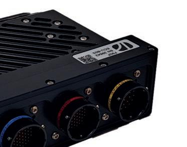
Life’s multi-functional ECUs do more than just engine control. Products like the F90 series are also able to look after the gearbox, di erential and other functions


As well as ECUs, Life makes a range of power distribution units (PDUs), which means it will have products relevant for motorsport in the years to come, whether the trend is toward electri cation, hydrogen or something else

Circuit boards, which are etched with copper tracks, are manufactured o site and then populated with hundreds of tiny components. Life’s top-of-the-range ECUs contain anything up to seven of these circuit boards
If what you make survives that, you’re doing pretty well. We’ve got a lot of experience with that, and our boxes are designed to cope with that sort of environment.’
However tough a device is built, it still needs to be tted correctly by the car or engine constructor, kept out of harm’s way as much as possible, and also kept cool –although it’s worth mentioning here that, typically, Life devices can function in temperatures from -40degC to 125degC, something the rm is quite proud of.
‘Where they are mounted is important,’ says Saunders. ‘Ideally, these boxes should be AV [anti-vibration] mounted and held on with rubber straps. They shouldn’t be bolted hard onto something. But they’re very, very strong. We once had an ECU back that was retrieved from the catch fencing at Indianapolis after a massive crash with an Indy Lights car. It still looked alright and, more importantly, it still functioned.’
Should a Life device cease functioning, though, the company has a system in place. ‘Each piece has a QR code on it,’ says Luke Anderson, production manager at Life. ‘We can follow every product through this QR code. We have our own piece of software that was written in-house that allows us to track the history of a board, or device. So, a bill of materials that it was built to, batch numbers, when it was made, any speci c information about that unit, whether it’s been back for a repair, whether we sent it out a week ago or 10 years ago, we have full traceability on that.’
There is also an EMC (electromagnetic compatibility) test chamber at Life, while some of its products have the coveted IP68 approval, meaning they are resistant to water (and dust) ingress for 30 minutes to a depth of up to 1.5m.
Talking of immersion, a brain without a nervous system might as well be bobbing in a vat, so from the start Life has also designed and made its own looms. This part of the operation is now run by GTEC, which Life bought a few years ago, but its founder, Gary Barker, still oversees the process, now at Life’s Basildon facility.
‘Once we’ve allocated inputs and outputs to those devices, and once we have a scheme that electrically works, we give it to the wiring guys,’ explains Saunders. ‘They will then quite often make what we call a hosepipe loom. They will go out to the car with a series of little garden hoses, all di erent ones to simulate the thickness of wiring looms, and actually wrap them around the car.
‘Once you’ve made a dummy loom that ts the vehicle, you look at the plan we’ve done for what amount of power is needed, then you calculate all your voltage drops. That then determines the gauge of the wire.
‘[Our looms aren’t] just a random bunch of wires; it’s a beautifully crafted winding of wires, twists within twists within twists, and it’s all laid up to give you the minimum overall size’
Andrew Saunders
So it’s an interim process. You can’t determine the gauge of the wire until you know how long it needs to be. And you don’t know how long it will be until you’ve laid out the wire in the car. If we just think of power as work, then the more work you need to do, the thicker your wires are going to be.’
All this is vital work, as thicker inevitably means heavier. The wire used is usually military-spec Raychem 55, and most of it is made from copper, or copper alloys, with diameters on the very fine side.
Measurements are given in US ‘gauges’ and, a little counter-intuitively, a lower number means a thicker wire. For reference, a 28-gauge wire is 0.32mm in diameter.
‘We usually use 12, 14, 16, 18, 20, 22, 24, 26 and 28 gauge,’ says Saunders. ‘In a typical loom, there’s probably at least six different sizes of wire, though most sensors will be on 26.’
These wires have to work together in the loom so, while they are tightly grouped, they need to be able to reject the cross-coupling ‘noise’ from other wires.
‘The wires are typically twisted,’ says Saunders. ‘So, if you’re sending wires to a position sensor, the ground and the signal wire will be a twisted pair. If it’s a 5V supplier, it will be a twisted triple. Then you might have three, four, five, six of those, and they’re wound around each other. This isn’t just a random bunch of wires; it’s a beautifully crafted winding of wires, twists within twists within twists, and it’s all laid up to give you the minimum overall size.’
Wires also need to be protected from abrasion and moisture and, given the demands of motorsport, it’s no surprise to learn budget PVC coatings are not used at Life. Most wires used come with a PTFE sleeving, often colour coded to help the person building the loom. There are also heat resistant coatings (DR25) and vibration resistant (HFT) ones, plus a plethora of other specialist materials.
It should be clear by now that building a motorsport wiring loom is no easy task. It’s a highly skilled craft, and there are eight people employed in this intricate work at Life.
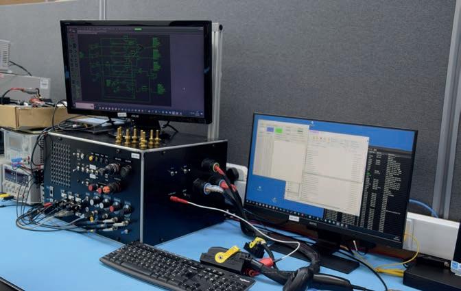
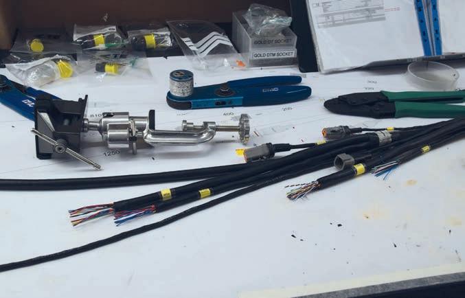
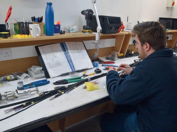
To make a prototype loom takes one person around 80-90 hours, and even production looms can take as long as 70 hours. All of which is quite understandable when you discover that the wires in a typical loom for a single seater can stretch for about a kilometre if laid end to end.
Yet while it’s convenient to talk of a loom in the singular, Life harnesses are designed to work in a modular fashion, which makes it much easier for fault finding and repair.
‘On a racecar, if the front left corner is smashed into the wall, you don’t want to have to change the wiring loom on the entire car,’ says Saunders. ‘You only want to change the front left corner. So, there will be a chassis loom, like a spine, and then there will be the front left corner harness and the other three corner harnesses. That way, if you damage one area of the car, it doesn’t trip a fuse that then has a negative effect on the other three corners of the car.’
Changing a harness, or a section of a harness, means disconnecting it, of course, and the connectors are another crucial part of the system. Life uses Deutsch connectors for its high-end products, some of which feature gold-plated copper pins.
‘They’re all IP68,’ says Saunders, ‘and very reliable. But it’s not only that. Regular automotive connectors have an application life, meaning you can only connect them and disconnect them a number of times. That might be 10, 20 or 30 times, and then they just wear out. If you think about your road car, I doubt the ECU has ever been removed, so that’s fine. Whereas with a racecar, you probably have the ECU on and off every weekend, or twice a weekend, or three times. Because one of the processes of a race weekend might be to test all the electronics, and test your spares. The connectors we use are rated for hundreds of re-uses.’
As you would imagine, all the harnesses are thoroughly tested before they are sent out, as are other products such as dash displays, of which the company makes a standalone item and also one that’s integrated into Life’s own design of steering wheel. The bodies of these wheels are made off site in carbon to Life’s design.
With hardware like steering wheels and dash displays, as well as its wide range of ECUs and PDUs, Life pretty much covers everything electrical in a racecar. That’s not all though. The company is also involved in general automotive, especially the high-end hypercar market. It supplies Czinger, for instance, as well as Singer Vehicle Design. Meanwhile, it developed a very accurate oxygen analyser during the pandemic, making around 8000 units, while it’s also provided products to the defence sector.
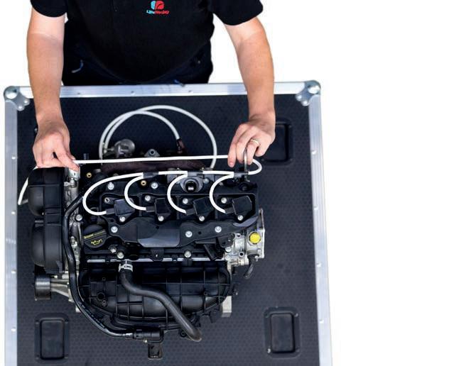
Fitting an engine loom. The wires are mil-spec and come in an array of thicknesses, depending on the power requirement. Various specialist coatings are used to protect them from heat and abrasion
‘I don’t think anyone produces electronics at the standard we do for the price we do, for the projects we do’
Mike Lancaster
Despite its impressive list of clients, Life Racing remains a relatively small player in the electronics arena, but one that is immensely proud to continually punch above its weight.
‘I don’t think anyone produces electronics at the standard we do for the price we do, for the projects we do,’ Saunders says.
Some of these projects have been very successful, too.
‘We’ve had overall third place at Le Mans, we’ve won at Daytona, Sebring and Petit Le Mans,’ Saunders continues.
‘We’ve also won multiple ALMS and ELMS championships in the past, and we won the World Touring Car Championship six times, before it went single-make ECU.
‘We were too late to the party for F1, and we will never be invited to join now [because F1 runs spec McLaren Applied electronics]. Because we’ve missed that, we have to operate in the area below Formula 1, and do the best job we can possibly do in that area. I think we do that very well.’
That said, while Life is not overtly involved in F1, the business is currently working on a top-secret project with a well-known team from that arena.
Deutsch connectors with a high re-use capacity are often used because, unlike in the mainstream automotive sector, devices on racecars are regularly removed and reconnected
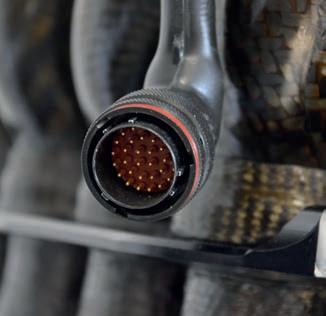
One thing Life Racing certainly doesn’t have is Formula 1 price tags, as Saunders explains: ‘The entry-level ECU from one of the big players is about £4700 (approx. $6100) to run a four-cylinder engine. Our entry-level unit to run the same engine is about £1500 (approx. $1950).’
Lancaster notes that opportunities at the higher levels of motorsport are becoming increasingly rare these days:
‘The challenge now is that some of the more sophisticated programmes that we have had, the [FIA] World Endurance Championship, and things like that, have melted away a bit because things are becoming more single make. For example, the British Touring Car Championship always uses Cosworth boxes. The challenge, then, is finding enough work in the highest level. We like to do high-level stuff, because we are capable of doing it. WEC and IMSA, that’s where we want to be.’
Life has certainly proven it’s capable of operating and succeeding in international championships, as well as supplying a high level of trackside technical support. Or ‘Life support’, as Saunders likes to call it. Though maybe ‘brain surgery’ would be more apt?


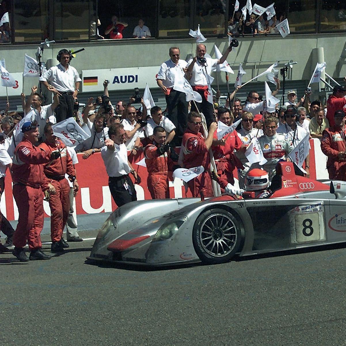
Audi’s
dominance defined the 24 Hours of
Le Mans
at
the turn of the millennium. A quarter of a century on from its first triumph, we look at the iconic Audi R8
By ANDREW COTTON
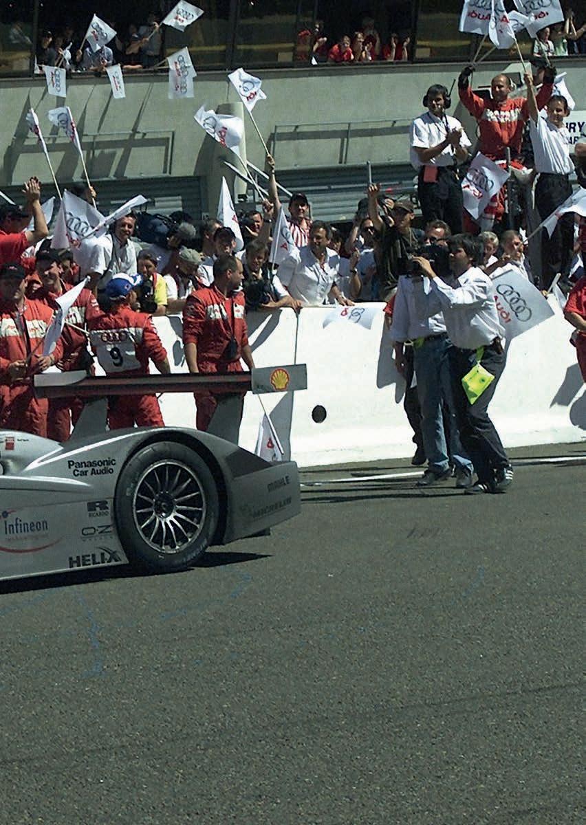
Audi is one of the most successful car companies at the 24 Hours of Le Mans, having won 13 of the 25 editions held this century. Making that statistic all the more incredible is the fact the German manufacturer withdrew after 2016, leaving it with a 72 per cent success rate at the famous endurance race. Only Porsche has won more, but its count of 19 started much earlier in 1970.
Audi’s era of achievement at Le Mans began in 2000, with the first iteration of the R8. That win was the first of three in succession, while customer teams then added two more before the now legendary car was replaced by the diesel-powered R10 in 2006.
The German manufacturer ran through several phases with its endurance programme, starting with the R8R that debuted at Sebring in 1999. That morphed into the re-designed R8 for the 2000 season, which firmly established Audi’s sportscar credentials in Europe, the US and at Le Mans.
After that came the diesel cars, starting with the R10 and R15, before the move to hybrid electric power with the R18. In that time, Audi shaped the most famous 24-hour race of all and, in doing so, defined an era of sportscar racing.
However, it was not a straightforward process at the beginning in the 1990s. Audi had long been interested in endurance racing, and initially looked at building a GT2 car. Out of that came the idea of a GT1 programme, with a view to racing in the FIA GT Championship. Audi in Germany gave serious consideration to both plans but, ultimately, they were canned in favour of building a prototype to compete for overall victory at the 24 Hours of Le Mans.
Prior to the development of the bespoke endurance racers, Audi had only previously built cars from production bodyshells. That included the DTM, IMSA, touring cars and rallying. All were successful projects in their own right, but none that started with a clean sheet of paper-designed carbon monocoque. There was no previous knowledge within the company of Le Mans prototypes, so it was no great surprise that Audi’s first car, the R8R, showed a design that closely mirrored that of another manufacturer.
The number of designers involved in the development of the Ferrari 333 SP is rather large, but one name stands out: Tony Southgate. The British designer worked on the 333 SP before moving to Audi, and the similarities between the two cars are clear to see. Both the Ferrari and the Audi R8R featured a double roll hoop over an open cockpit; both housed the radiator in the nose of the car; both had a non-stressed engine and both used carbon chassis built by Dallara.
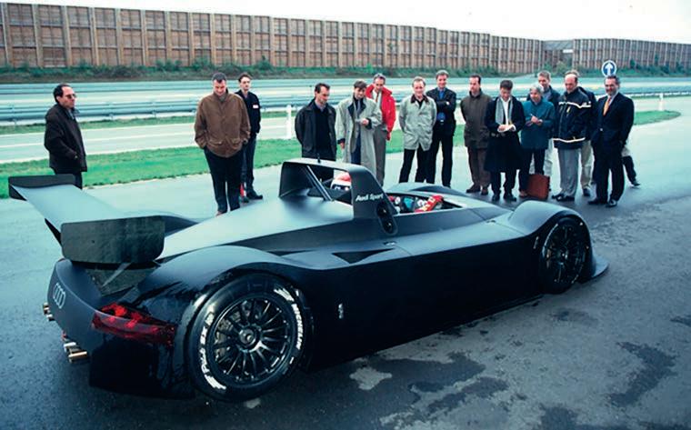
‘The GT1 project was shown to me and to Dr [Franz-Josef] Paefgen [Audi’s chief executive officer] before we decided that LMP could be the future,’ said Dr Wolfgang Ullrich, head of Audi’s motorsport activities at the time. ‘Richard [Lloyd] stood with his group of people, saying we have a concept, and Dr Paefgen and I went to see the concept.’
The decision to move into prototype racing rather than run a modified version of a production car was not taken lightly. ‘We came with our car, which was a 333 SP Version Ingolstadt, but it was the first time that this group of people made a prototype from zero,’ says Ullrich. ‘Wolfgang Appel [head of chassis design] did a lot of things before, but nothing like this.’
Audi was preparing a car to compete in a golden era of endurance racing for manufacturers. Although there was no championship surrounding the Le Mans race for prototypes, the 24-hours was still the jewel in the crown, and all the stars aligned for the 1999 edition.
Mercedes developed the CLR for the 1999 race, an evolution of its CLK GTR, which had defeated Porsche and McLaren in the 1997 and 1998 FIA GT Championships. Both had withdrawn from the series in 1999, leaving it to GT cars alone.
Toyota had the magical GT-One (TS020), Nissan the R391, BMW the V12 LMR and Panoz brought the first iteration of its LMP-1 roadster. While there was confidence in the design team in Germany in the creation of the R8R, there was enough doubt that Paefgen decided on a back-up plan, and so was born the Audi R8C. This was a closed cockpit car that featured the same engine as the R8R, but was different in almost every other respect.
While there was confidence in the design team in Germany in the creation of the R8R, there was enough doubt that [Dr Franz-Josef] Paefgen decided on a back-up plan, and so was born the Audi R8C
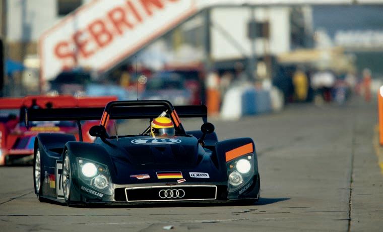
Audi had bought the old TOM’s factory in Norfolk, UK, from where Toyota’s satellite team had run its Formula 3 operation. The facility had its own manufacturing capabilities, including an autoclave, so could design and manufacture a full car. Under the watchful eye of German, Sigi Krauser, and Japanese, Hiroshi Fushida, the factory was tasked with developing a closed chassis, to LM-GTP 900 regulations, housing Ulrich Baretzky’s V8 engine. The car ran with an Xtrac gearbox, rather than the Ricardo fitted to the R8R, the tyres were a different size, as were the engine air restrictors, both by regulation. Southgate sat between Audi UK and the mothership in Germany and oversaw the two projects.
At the heart of both cars was a 3.6-litre twin turbocharged V8 engine. The powertrain had been developed by Baretzky in Neckarsulm, Germany, that was able to simulate a lap of Le Mans on a dyno. That allowed full durability
and reliability testing to take place before the engine even went into a car.
This twin-turbo engine would go on to form the basis of six Le Mans winners, including the 4.0-litre DI version that was used in the Bentley Speed 8, which famously took victory in 2003.
The competition was tough, though, and the R8R made its race debut at the 12 Hours of Sebring in March 1999. Run by Reinhold Joest’s team, the two cars finished third and fifth after a steady, if unspectacular, run. It was not a failure by any stretch, especially at such a tough circuit, and the race miles were important for the team and the car.
At a launch in the south of France weeks later, the R8C was presented to the world for the first time. It was beautiful, decked out in iconic silver, and its looks belied the fact it had
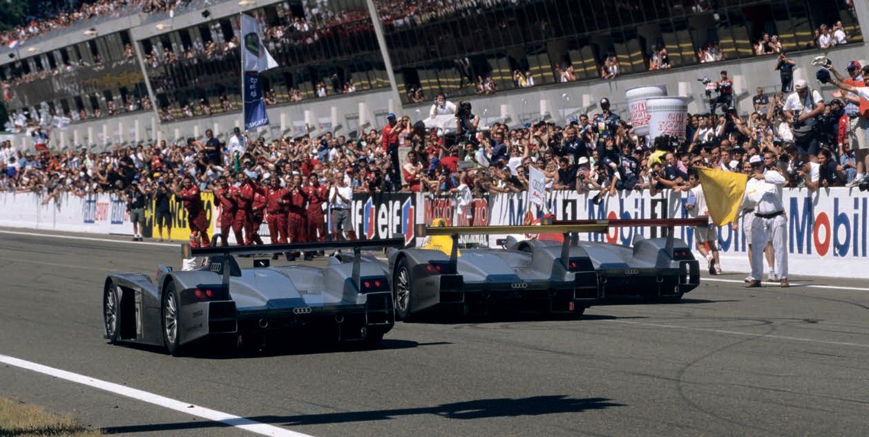
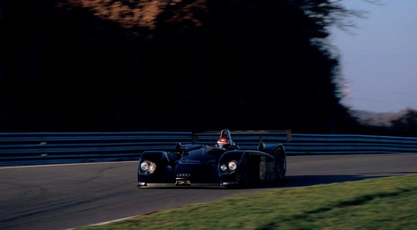
been put together in a fraction of the time it had taken Audi to build the R8R. There were cooling problems with it and work had to be undertaken to make the gearbox effective.
Due to the short development time, the R8C was not fully ready for Le Mans that year. It only just qualified for the race, and only then by sleight of hand. Driver, Andy Wallace, lost a door in the pre-qualifying session and there were so few spare parts that a member of the team was dispatched to retrieve the door from the woods. Having found it, the team taped it back onto the car, though it was not serviceable. After setting a time good enough to qualify for the race, Wallace parked the car against a wall, and climbed out of the passenger side to avoid arousing suspicion that the car was illegal.
In the end the 1999 race was notable for many different reasons, none of them associated with the new Audi. BMW had read
the rulebook differently to Audi, and produced a single roll hoop design for its V12 LMR. The car, designed by Peter Stevens and built by Williams, went on to dominate the race. So much so, at one point one of the BMW team’s cars led by four laps, so when J J Lehto had a suspension collapse onto the throttle linkage, putting him into the wall, it took the other competitors nearly 20 minutes to knock his car off the top of the timing screens.
Mercedes’ efforts were well documented at the time. Its car was slow compared to the BMW, and particularly the Toyota. It had a short wheelbase and long overhangs and, like all the prototypes, a flat floor. All the manufacturers involved were concerned about the front lifting, particularly over a crest and when travelling close behind another car, and Mercedes had warned its drivers to avoid such situations.
Mark Webber was the first to experience his CLR taking off during practice, and suffered the same fate in warm up on Saturday morning. Peter Dumbreck then famously lifted off the circuit and crashed into the trees, thankfully without major injury. Toyota and BMW, meanwhile, slugged it out for the win, the latter’s V12 LMR ultimately taking the chequered flag.
Audi, despite finishing third, knew it needed a radical overhaul of its car if it was to win. The first decision to be taken was whether to adopt a closed chassis, like the R8C, or an open chassis like the R8R. Ullrich was clear that enough had been seen, even just with the early version of the closed car, to convince him the open design offered advantages.
Open cars offer fans the chance to identify the drivers, which was a consideration in the US. The larger rear tyres and smaller air restrictors of the open cars, by regulation, were advantageous, and there is a simplicity to the open-top design. A closed car requires doors, for starters, and the hinges on them are notoriously difficult to manage.
Windscreen quality was also an issue at the time, with a narrow opening for the glass and a difficulty keeping a clear windscreen, even on later cars, notably those from Bentley.
So, with the decision taken to have an open cockpit, Audi needed a development plan to make it to the front of the grid. BMW remained in the running, although scaled back its involvement in endurance racing to focus on Formula 1. Toyota and Nissan, meanwhile, ended their programmes and Mercedes, of course, withdrew (2025 will mark the first time the German manufacturer has lined up on the grid at Le Mans since, albeit in the GT ranks).
Next to drop out was Porsche, which built and tested the LMP2000, but never raced it. That left Panoz, BMW, Audi and Cadillac to contest Le Mans with factory teams in 2000.
Work on Audi’s new car started in earnest in June 1999. The first thing to change was the overall chassis design concept, with the marque opting for a single roll hoop and a relocation of the water radiators to the side, rather than the front. This improved airflow in general, but also prevented the hot air evacuated from the radiators rising into the cockpit, which annoyed drivers of the R8R.
The cockpit was smaller than the previous car, and every effort was made to reduce the c of g height and concentrate the weight between the wheelbase. Along with moving the radiators to the flanks, the front and rear suspension systems were redesigned to place the coilover suspension lower in the chassis. This also helped reduce frontal area.
The Ricardo gearbox was updated, featuring a new magnesium casing, while changes to the internals further contributed to shaving 15kg from the gearbox alone.
Aerodynamically, there were a number of big updates, including to the diffuser, floor and body panels, which fitted better following development work undertaken at Fondmetal Technologies.
In total, the frontal area of the car was reduced by a staggering 20 per cent compared to the R8R, while there was a 10 per cent improvement in the lift-to-drag ratio.
The engine was also further developed, with new camshafts, a revised design for the inlet and exhaust ports, an increase in the compression ratio and a modified oil system. The engine was also included as a fullystressed member for the first time, which eliminated the need for the aluminium cradle used in the R8R, and overall car weight was 50-60kg less than the R8R.
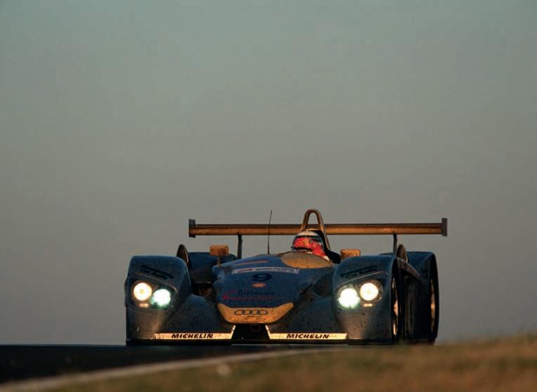
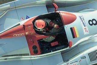
The frontal area of the [2000] car was reduced by a staggering 20 per cent compared to the R8R, while there was a 10 per cent improvement in the lift-to-drag ratio
The engine featured major gains in torque output and driveability, while fuel consumption was improved by eight per cent. This allowed the Audis to complete 13-lap stints with relative ease.
The engine was also put on a diet, losing 12kg, which brought weight saving from the engine and gearbox to 27kg.
The new car debuted at Sebring in March 2000 and took victory, despite a late stop to bleed the brakes (a problem that affected both cars in the race). It then continued to be developed between the Florida race and Le Mans. The intervening American Le Mans Series rounds, held at Charlotte and Silverstone, were contested by an updated version of the R8R, which was pressed back into service for those two races only.
Development of the R8 between March and June included improvement of the aero package, and the whole platform, with damper and spring rate testing done on the rigs. More downforce was dialled into the car to counter the rear downforce increase that was prescribed by the new rules, helped in


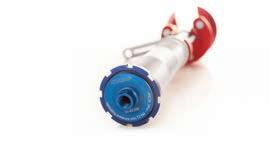
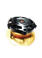

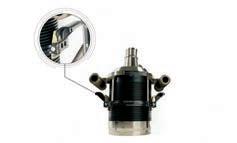
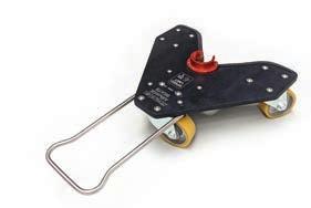

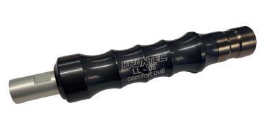


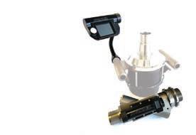
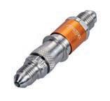
part by new front louvres introduced to relieve pressure over the front wheels, and increase potential take-o speed following the Mercedes dramas of 1999.
For the 2000 season, cars raced with smaller air restrictors, smaller wings, Gurney aps and the openings over the front wheels, all of which slowed the cars dramatically compared to the previous year.
Audi started from pole position and swept the podium. Such was the dominance of the R8 that the fourth-placed car, a CouragePeugeot, nished 24 laps behind, around 90 minutes at full racing speed.
Although the R8 was dominant, the manner in which Frank Biela, Emanuele Pirro and Tom Kristensen won the race was slightly controversial. Pre-race, the Joest team had decided to change the rear end of each car, a quick x that would take less than ve minutes and cost a single lap thanks to intelligent design. The thinking was that if there were a gearbox, clutch, suspension or aerodynamic issue, or an accident, the entire rear end could be changed quicker than it could be repaired.
Although the plan was to change them all, the winning car did not receive the update. It stayed out using the original gearbox, and therefore had a lap advantage that Allan McNish single-handedly tried to recover during an epic dawn stint on the Sunday.
The team of Biela, Pirro and Kristensen went on to win Le Mans again in 2001 and 2002 in the Audi R8. In the rst of those years, the car featured the manufacturer’s new FSI technology, which further improved fuel consumption and reliability.
The nal win of the R8 came in 2005, this time with Kristensen, Lehto and Marco Werner, after which it was replaced by the R10, the rst of the diesel-powered prototypes from Ingolstadt that ushered in a new dawn for e ciency.
Despite the regulations consistently slowing the R8 through less power and fuel, the car was beaten just once at Le Mans, in 2003 by Bentley. By then, the R8 was in customer hands, nanced and run by the local importers in Japan, the US, the UK and France, while the factory team focused on developing its forthcoming diesel technology.
Under factory and customer operation, the R8 raced in the ALMS and the Le Mans Endurance Series (now ELMS), winning titles and establishing the brand as a sportscar manufacturer in North America. It won Le Mans twice more, in 2004 with Japanese out t Team Goh, and in 2005 with Champion Racing from the US. As attention moved on to the R10 TDI, the R8 was put out to pasture, but its legacy secured Audi’s place at the heart of endurance racing for a generation.
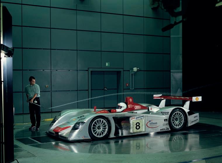
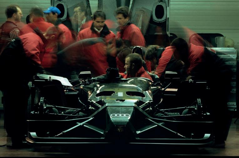

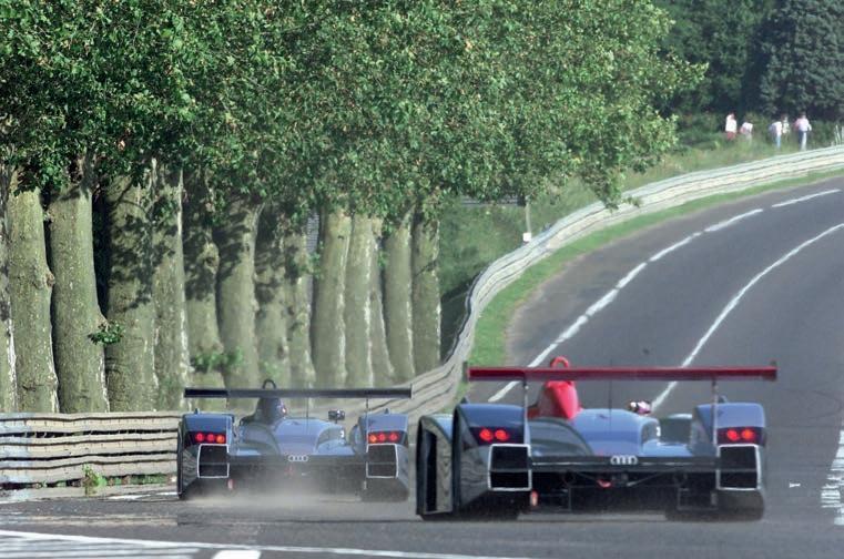
Despite the regulations consistently slowing the R8 through less power and fuel, the car was beaten just once at Le Mans, in 2003 by Bentley [though] by then, the R8 was in customer hands


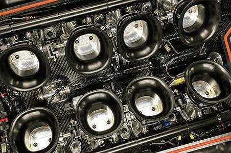


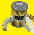


All the components, are carefully measured for each valve build, and recorded. This valve has the tightest loop of any valve we have tested:


Cup and INDY 500 cars


EFI Injectors, all makes ofPressure


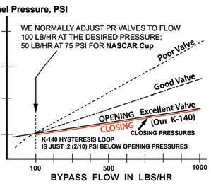
and LucasMechanicalMeteringUnits,need 3 micron protection, but 3 micron filters plug up too quickly, so most racers use10 micron, which is too coarse. We made this new element for NASCAR Cup cars: 10 micron premium paper top layer to take out 95% of the dirt, with a 3 micron precision Fiberglass lower layer. EFI Injectors,
Kinsler.com


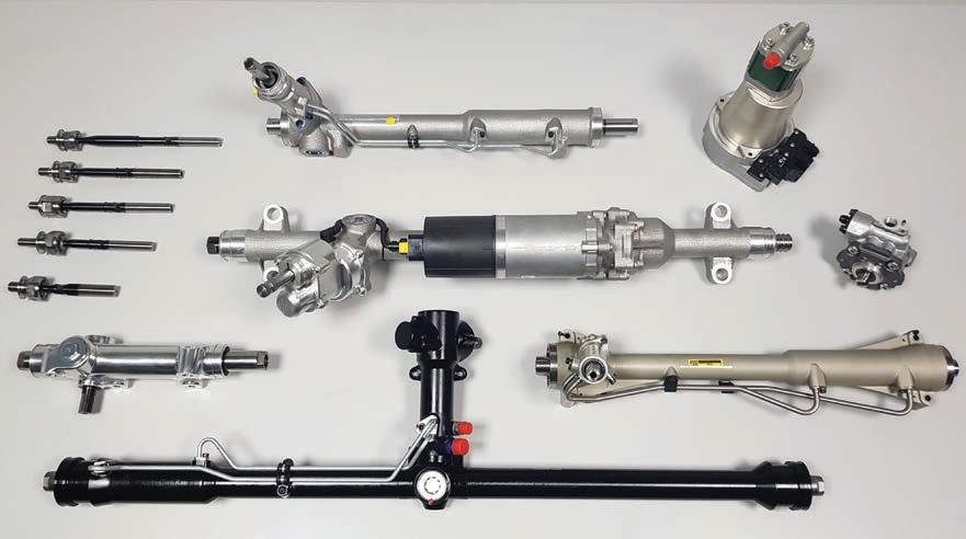


With BoP ever-more prevalent in motorsport, accurate torque measurement has become a critical issue. Racecar investigates the latest advances
By LAWRENCE BUTCHER
The ability to accurately and reliably measure torque on a moving racecar has become a hot topic across racing series, concurrent with the rise of Balance of Performance (BoP). With defined power curves now fiercely enforced, sensing technology capable of providing the high levels of accuracy required, repeatably, without
the need to be constantly recalibrated is critical. Meanwhile, those teams and racers subject to the edicts of BoP need to be confident that the tools used to determine whether they are within the regulatory bounds are reliable.
Of course, accurate determination of torque has been an important matter since long before BoP’s presence
was felt, but it is the arrival of true, contactless torque measurement that has made its on-car use feasible.
In the past, powertrain torque was measured on a dynamometer, and these are still used extensively for powertrain calibration and testing. There used to be just two main options for torque measurement, twist angle and strain gauging.
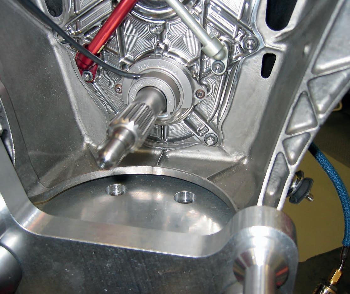
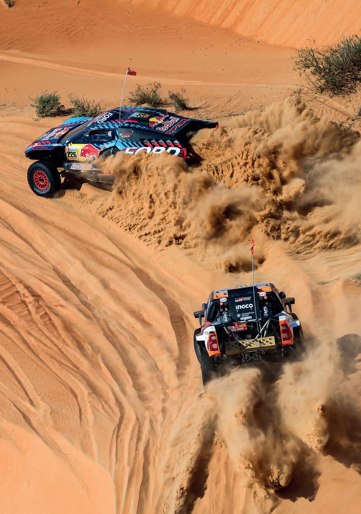
Sensing technology capable of providing the high levels of accuracy required, repeatably, without the need to be constantly recalibrated, is critical

The twist angle method generally requires a portion of the shaft (usually the one connecting the dyno to the engine, or electric motor, on test) be reduced in diameter, allowing it to twist under load. A pair of toothed discs are then attached at either end of this portion and the twist angle determined using the phase difference between magnetically or optically-detected tooth / space patterns on each of the discs. Because the discs are rotating at the same rate as the output shaft, this allows the torque to be measured at each revolution of the engine. The addition of extra toothed wheels to the system allows for greater resolution of the torque reading. Whilst accurate, such a system is clearly not a practical fitment to a racecar.
The second method relies on strain gauges, which are used extensively for on-car load measurement of a variety of components. Basic strain gauges commonly consist of an electrical resistor constructed from a foil section bonded to a dielectric backing. When the gauge is stretched, or compressed, its electrical resistance changes, and this variation can be related to the amount of force exerted on the material.
However, the variation is very small, and to assess the strain accurately requires precise measurement of very small changes in resistance. To measure such minute variations, strain gauges are almost always used in a bridge configuration with a voltage excitation source. The traditional configuration is a Wheatstone bridge, which consists of four resistive arms (bridges) with an excitation voltage, VEX, applied across the bridges. When it comes to measuring torque on a shaft, four strain gauges can be arranged in a circuit attached to the shaft, each gauge at 45 degrees to the shaft axis, with gauges one and three, and two and four, diametrically opposite each other. As the shaft twists, a shear strain is created causing gauges one and three to elongate and two and four to compress. This creates an unbalanced bridge, with resistance reducing on the gauges subject to compressive strain and increasing on the pair under tension, and the electrical output corresponding to the torque value.
One aspect that does need to be considered with strain gauges is the effect of temperature and other external factors on their output, as the resistance
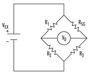
The traditional configuration for strain gauges on a racecar is in a Wheatstone bridge, where an excitation voltage is applied across four resistive arms, or bridges
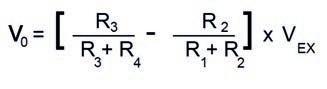
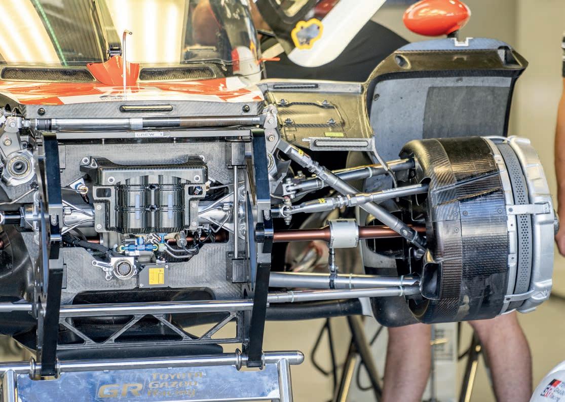


Importantly, measuring surface stress by magnetoelastic methods is non-contact, and the sensors can be packaged in a compact and robust fashion
of most conductive materials varies with temperature. The solution is to use two strain gauges in each bridge, one of which is a ‘dummy’ gauge placed transversely to the applied strain direction, meaning the strain has little effect on it. The reading from this gauge acts as a reference for the variation in resistance with temperature, which can then be subtracted from the reading from the gauge fixed along the axis of strain. Both will be affected by temperature in the same way, the difference between the readings being a measure of the strain.
Though a reliable method of measuring torque, strain gauging has its limitations when it comes to on-car use, not least because the sensors require either a slip ring set-up to transmit power to the gauges and take the signal, or a wireless telemetry system incorporated into the shaft.
Given the various constraints of the torque measurement methods covered so far, an alternative is needed for practical and reliable on-car use under racing conditions. Enter the phenomenon of magnetoelasticity.
At the end of the 1990s, the Stewart-Ford Formula 1 team was investigating methods of non-contact torque measurement, and drew on the capabilities of partner, Visteon. Ruling out strain gauges with telemetry, a system that required nothing be attached to the driveshaft was deemed desirable. The solution settled on was magnetoelastic band sensor technology, which has evolved into the sensors used today in the FIA World Endurance Championship for BoP-related torque measurement.
Magnetoelastic torque sensors produce signals that are a function of torsional stress, rather than strain, which means they can be made much stiffer mechanically than conventional elastic torque sensors. They also offer a very high frequency response, up to 5kHz for the devices used in racing today. Importantly, measuring surface stress by magnetoelastic methods is non-contact, and the sensors can be packaged in a compact and robust fashion.
There are two types of magnetoelastic sensor. Both record magnetic variations due to surface shear stress, but in different ways.
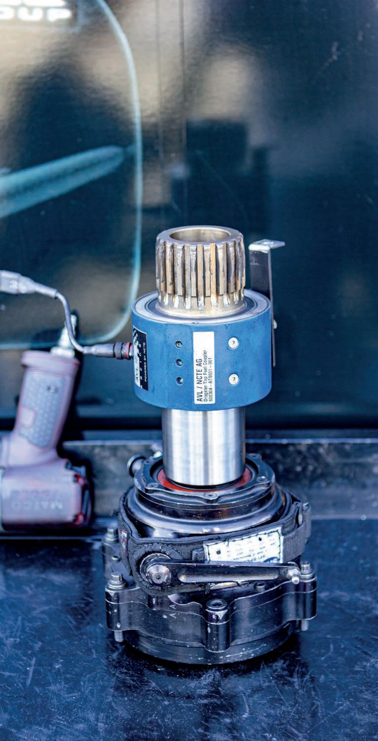
The first type measures magnetic permeability changes in the shaft surface caused by stress-induced magnetic anisotropy – which affects the permeance of a magnetic flux path – using a magnetising source and a pick-up (sensing) coil. These are PB Type 1 sensors.
The second type is referred to as PB Type 2, where the stress-induced magnetic anisotropy causes a permanently magnetised magnetoelastically active element to generate a measurable magnetic flux.
The main advantage of both sensor types over traditional torque sensing methods is they do not need physical contact with the rotating part. They also remove the need for features such as thinned sections to permit twist; they can simply be incorporated into the rotating shaft to be measured. However, Type 1 permeability-based magnetoelastic torque sensors have several disadvantages that limit their use in a racing environment. Notably, the variable being measured –permeability – is not solely dictated by the applied torque. Even in a controlled environment, permeability can vary with temperature and magnetisation. The changes caused by these factors can exceed the shifts in permeability that are a function of torque, leading to unreliable results.
Type 2 sensors are much more suitable for use in racing. They have many of the benefits of Type 1 sensors and overcome most disadvantages. The sensors can be incorporated into a shaft in two ways. For shafts made from a ferro-magnetic
material, a section of the shaft can be magnetised. Where this is not possible, for example with a shaft made from a composite material, bands of magnetic material can be bonded into the shaft.
The stress created as torque is transmitted along the shaft, causing the magnetic field of each magnetised section to rotate towards the nearest positive stress direction and away from the nearest negative direction. This re-orientation of what is naturally a circular magnetisation results in a net axial magnetisation component.
Where this component leaves the edges of the polarised bands in the shaft, a magnetic field is created in the space around the shaft that can then be measured by highly sensitive magnetic field sensors. This gets around the problems associated with measuring the permeability, as only stress will alter these fields, allowing for accurate and repeatable readings to be taken. Hence the reason that, to date, magnetoelastic sensors have been the favoured means of on-car torque measurement.
Units from MagCanica, the company set up to commercialise the technology developed by Visteon at the turn of the century, are now mandated in a host of FIA series, as well as the IMSA Sportscar Championship.
A SAW transducer can have a very large signal bandwidth compared to a conventional sensor of the same size
Magnetoelastic torque measurement has been considered the gold standard for racing applications for many years now. However, surface acoustic wave technology (SAW) is also now making its presence felt, notably in IndyCar. These sensors rely on measuring changes in the properties of SAWs across a substrate as the stress within the substrate varies. SAW transducers consist of an inter-digital array of metal electrodes deposited on a piezoelectric substrate, normally quartz. The electrodes that make up these arrays alternate polarities, so that an RF signal of the right frequency applied across them causes the surface of the crystal to expand and contract, generating the surface wave.
The surface velocity of the acoustic waves is 10-5 of the speed of light, so the acoustic wavelength is much smaller than its electromagnetic counterpart. For example, a signal at 100MHz with a wavelength of 3m would have a corresponding acoustic wavelength of about 30µm. This is important because it means a SAW transducer can have a very large signal bandwidth compared to a conventional sensor of the same size, the result being that much higher resolution measurements can be obtained without an increase in packaging size. This allows for the sensors to be packaged into very tight spaces. Consequently, one of their first uses in motorsport was by McLaren to monitor KERS output in Formula 1’s first hybrid era. SAW transducers intended for strain measurement are attached to the material to be stressed, for example a driveshaft. The main supplier of this type of sensor into
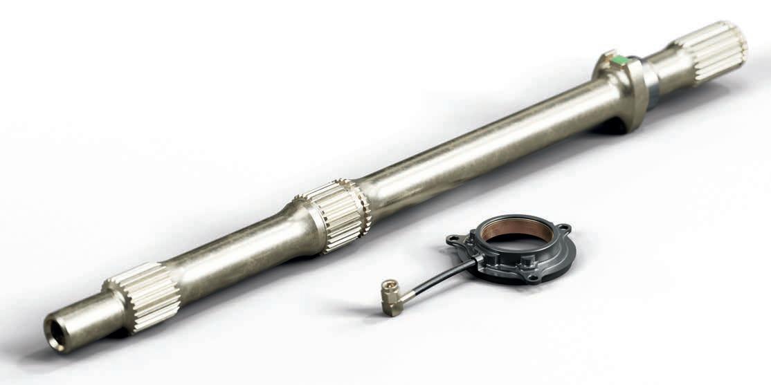
motorsport, Transense Technologies, has developed SAW sensing elements that use two to three resonators each. This is done to cancel the influence of any variability in the reactance of the antenna on the measured value. Notably, SAW sensors can measure both strain and temperature as variations in the properties of the quartz substrate at varying temperatures can be accurately quantified and accounted for in the signal processing unit for the sensor.
The transmitted waves’ frequency depends on the distance between the electrodes on each inter-digital array, with the waves travelling at right angles to the electrodes. Therefore, any change in shaft length alters the electrode spacing,
SAW transducers are not impacted by the presence of strong magnetic fields, as the wave is ‘mechanical’ rather than electromagnetic
and so the operating frequency. Tension increases the frequency, compression reduces it. Using a suitable signal processing device, these changes in the wave’s frequency can be used to determine torque as a function of strain in the surface substrate. In effect, the transducer acts as a ‘frequency dependent’ strain gauge.
One of the biggest benefits here is that SAW transducers are not impacted by the presence of strong magnetic fields, as the wave is ‘mechanical’ rather than electromagnetic, making them particularly useful for measurements of electromagnetically noisy devices, such as electric motors. For example, in an MGU-H.
The signals generated by SAW transducers can be collected by a rotary RF receiver, with the sensor reflecting a back scatter signal to the RF interrogation unit. This signal shows the frequency of the sensor oscillation, from which can be derived the torque value. If needed, the frequency response of the sensor, dependent on the RF receiver capabilities,
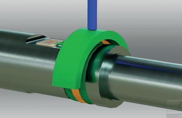
motor racing applications, this is most commonly a driveshaft. Transense Technologies SAW shown
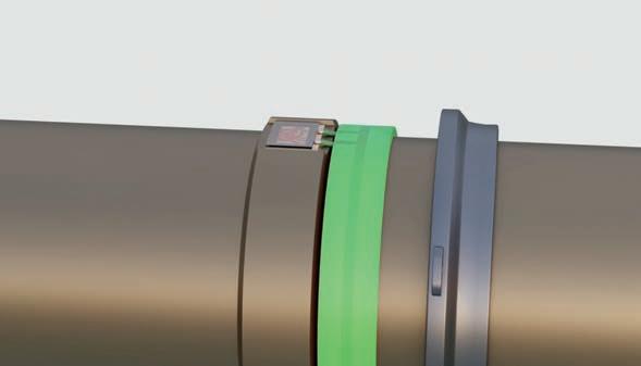
can be in excess of 5kHz, capable of recording the position of even very high-speed shafts.
SAW transducers have been used by IndyCar for its BoP torque measurements for over a decade (with a McLaren Applied sensor incorporating Transense’s technology). Importantly, these sensors can be used on any material, unlike magnetoelastic sensors, which require the components being measured be constructed from specific metals with suitable magnetic properties. Other benefits include the compact, rugged nature of the sensors and characteristics that mean they do not need to be recalibrated, with only a few parts that can be damaged or displaced.
On-car torque sensing is now commonplace in motorsport, and not just from a regulation compliance perspective. The ability to package SAW sensors in tight spots opens up the possibility of monitoring torque throughout the driveline, something that is becoming increasingly important when hybrid elements are incorporated, such as in the current IMSA LMDh transmission.
Transense Technologies was established in 1991 and listed on the London Stock Exchange’s AIM market in 1998. It develops and supplies sensor systems using Surface Acoustic Wave (SAW) technology. Transense has a large intellectual property portfolio and experience in the design and implementation of SAW technology for sensing applications.
In motorsport, the company has had a partnership with McLaren Applied for over 10 years developing high-performance torque measurement systems that started in Formula 1, before expanding into IndyCar and elsewhere.
Outside of racing, Transense is proven as a reliable and accurate way to measure torque and temperature in harsh applications where other sensor technology cannot deliver the required level of performance. For example, GE Aerospace is using Transense SAW technology for torque measurement in several engine programmes including its new T901 engine, initially developed to upgrade Black Hawk and Apache helicopters with more power and improved efficiency.
Transense is also working with Airbus on sensors for nextgeneration aircraft landing gear and several other high-performance torque and temperature sensing projects with major global aerospace engine and component companies.
In mainstream automotive, the ability of SAW to measure torque and temperature inside electric motors creates opportunities for sensing rotor temperature, allowing the reduction of rare earth magnet materials or delivering higher power density.
Adding real-time motor output torque measurement gives closed loop motor control to improve functional safety and drive system performance. The company is working with Protean electric in the UK and Tier 1 suppliers in the US and Europe on such sensors for their electric drive systems. Transense is also working to enable improvements in robotics, for instance the ability to measure torque on stiffer components than conventional sensors with no zero drift and high levels of accuracy.


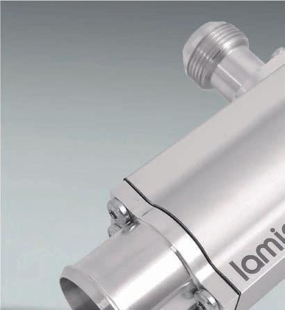


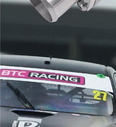


●
●


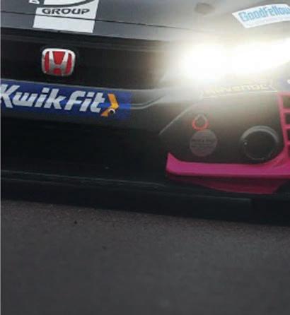


Bosch has leaned heavily on its LMDh prototype braking system to deliver Robert Wickens the latest in brake-by-wire for his Corvette IMSA drive
By ANDREW COTTON
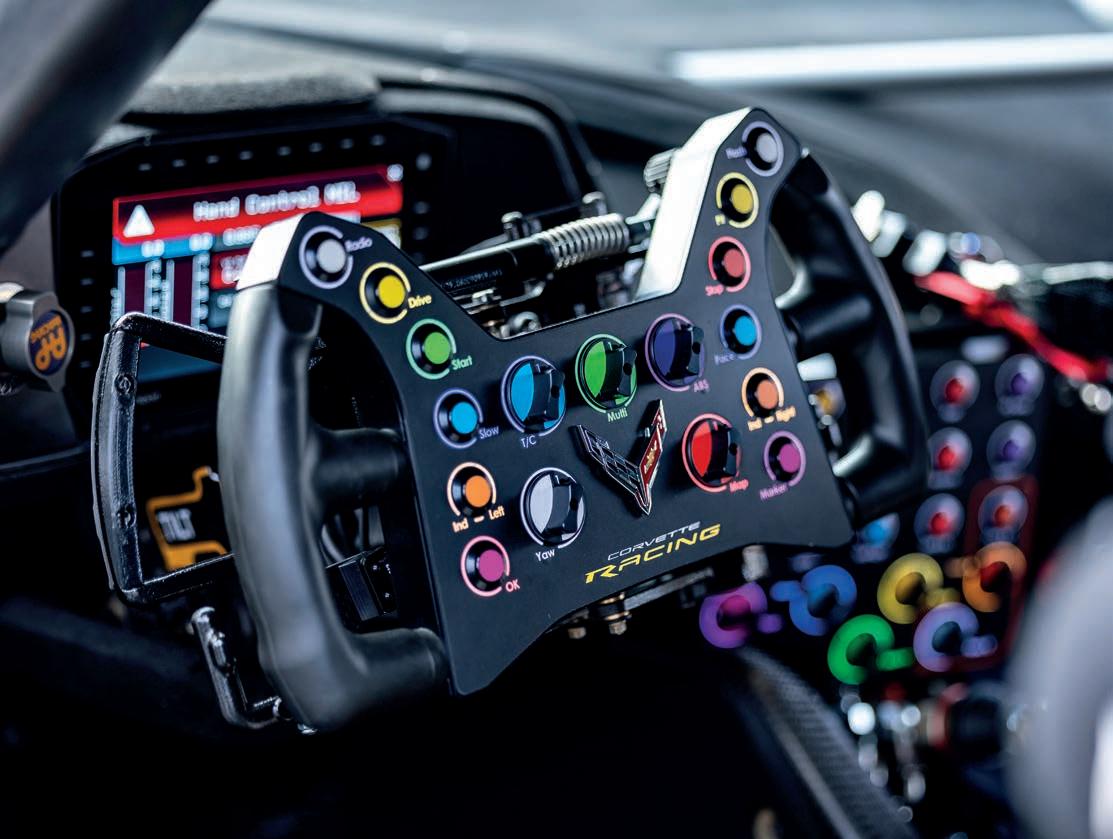
Robert Wickens’ return to top-flight motorsport following his devastating accident at Pocono Raceway in 2018 has been often told. The Canadian, who suffered a spinal cord injury, returned to racing in spectacular fashion in 2022, competing in the second-tier IMSA Sportscar Challenge with a Hyundai Elantra N TCR. Using the Hyundai with adapted hand controls, he won the drivers’ championship in 2023, alongside his co-driver, Harry Gottsacker.
This year, Wickens has taken the next step and transitioned to running in the top-tier IMSA Sportscar Championship with DXDT Racing. Competing in the GTD class in
a Chevrolet Corvette Z06 GT3.R, his season started at the Long Beach Grand Prix in April. It has been a long road for Wickens, and also the engineers developing his hand control system. The first iteration of his hand control system fitted to the Hyundai in 2022 was an hydraulic system that used a ring at the rear of the steering wheel to control braking and acceleration pressure. There is no criticism of the system, and it allowed Wickens to return to competition, but it was hard for the former DTM driver to use. Not only did he have to apply a lot of physical pressure to make the ring work, its hydraulic actuation carried latency, which delayed peak pressure application of the brakes.
While the system delivered braking force the moment Wickens demanded it, it took time to reach peak pressure, which he had to adapt into his driving style. Despite that, he was able to run competitively before switching to a Bosch system for 2024. This was based on the company’s LMDh parts which had been introduced in 2022 and could now be adapted to Wickens’ needs.
For the 2025 season, after a year of development, Bosch’s system was then transferred to the mid-engine, rear-wheeldrive Corvette to compete in top-flight sportscar racing.
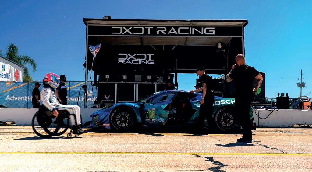
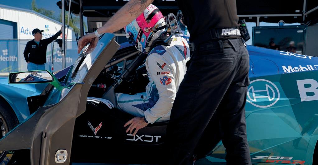
Bosch had originally been asked to be part of the Wickens story, but development of the electronic braking system for the Hypercar class took priority
Bosch had originally been asked to be part of the Wickens story, but development of the electronic braking system (EBS) for the Hypercar class took priority. Once they had successfully debuted, the company could return to the Wickens programme with a fully developed EBS.
‘I was actually at his first test in the Hyundai doing something else for Bosch,’ recalls Bosch Motorsport senior engineer, Jordan Krell, who has been instrumental in developing the EBS for Wickens in the Corvette. ‘That was when we were developing the EBS, so we weren’t ready yet. A couple of years passed, and we worked on LMDh to make an EBS and got everything sorted
from that perspective, and then they approached us again. That was in late 2023. That’s when we started putting together what it would look like for the TCR car.
‘We developed the system with the TCR car, and worked around a lot of what already existed, such as the steering column. He already had a ring on the car for the throttle, and was still pulling on the master cylinder with a ring. We were able to get most of the latency out of the system. Before, he had to pull harder on the brake rings to generate full pressure; it was more like the time it takes for your hands and body to be able to generate that much force, whereas now that force input curve is quite a bit less.’
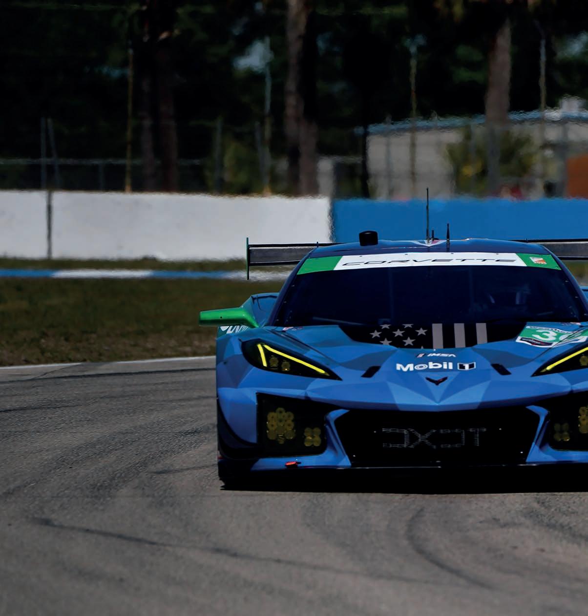
The standard Corvette Z06 GT3 racecar has paddles on either side of the steering wheel, each capable of upshifts and downshifts. In the Hyundai, Wickens primarily applied throttle with his right hand and upshifted with his left, and then applied the brake with his left hand and downshifted with his right. However, certain corners on certain tracks made that difficult and so when the system was switched to the Corvette, and paddles for throttle and brake were
introduced, Wickens has set himself the target of retraining himself to use either hand for whatever function the car needs.
The paddles for the braking system are controlled by a damper that runs across the top of the steering wheel, which can also be set up for optimum performance, in the similar way to a suspension spring. Performance, in this case, is tuning brake feel.
‘Before, he had to pull harder on the brake rings to generate full pressure… whereas now that force input curve is quite a bit less’
Jordan Krell, senior engineer at Bosch Motorsport
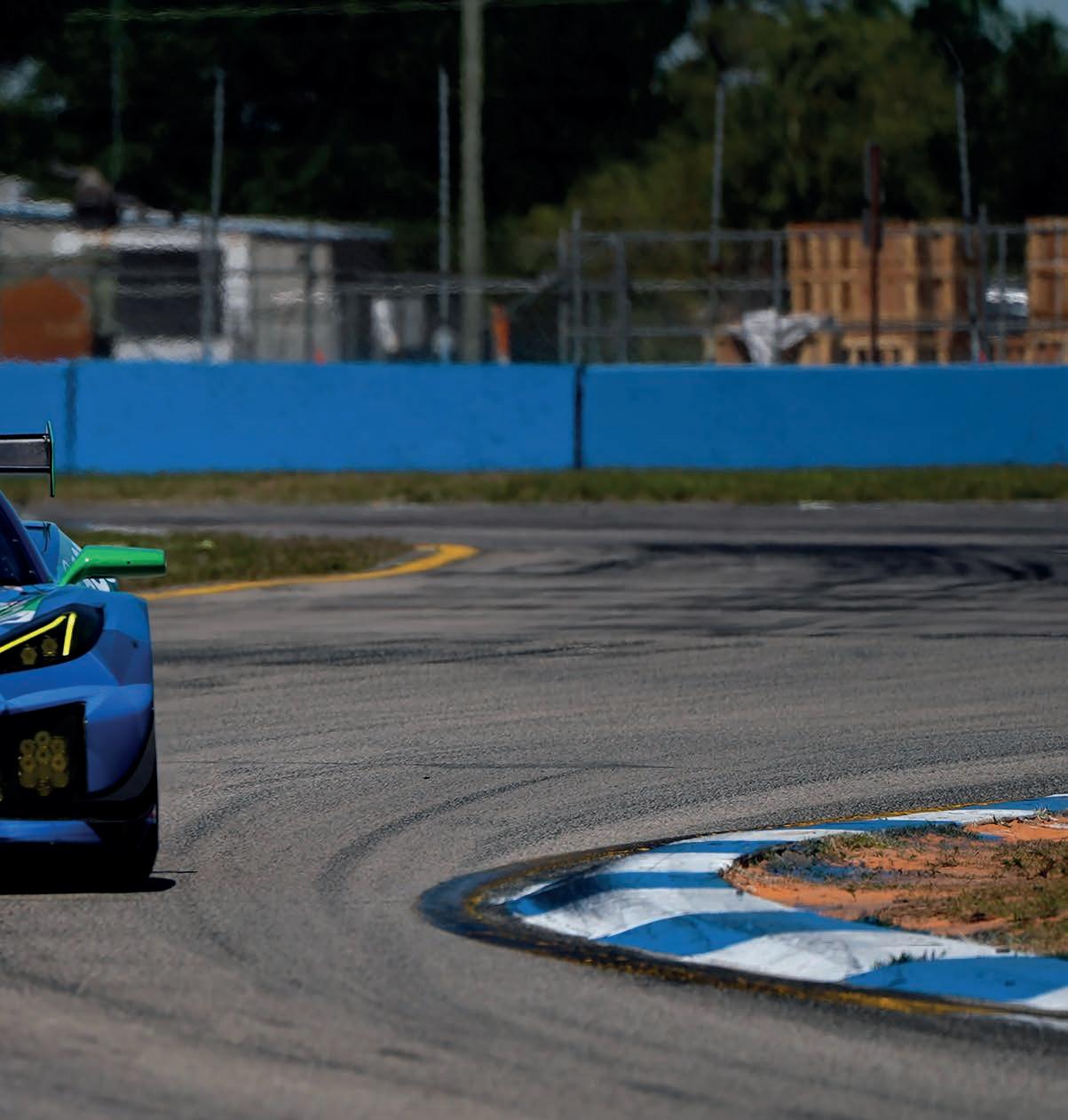
‘It still needs to be enough force for him to be able to actuate and control the pressure, but it’s less on the GT3 system [than the TCR],’ says Krell. ‘So that’s where the biggest difference is in latency between last year’s system and this year’s.’
As the LMDh car is a hybrid, the braking system is electronic. That is to mask the different feel on the brake pedal when the battery is harvesting energy, which reduces the pressure on the pads and discs.
The Corvette, on the other hand, has, by homologation, an hydraulic braking system operated by the foot pedal. This is used by Wickens’ team mate at Long Beach, Tommy Milner. Other drivers will compete with Wickens in other races during the year.
Wickens’ electronic system therefore sits alongside the hydraulic one, but either remains passive when it is not needed. During a driver changeover, the incoming driver flicks a switch in the cockpit to
determine which is used. While the switch changes the primary controls, it does not carry over to items such as brake bias. That still has to be manually adjusted.
‘We found that you have to switch your mindset away from pressure to torque,’ says Krell. ‘You are looking at the torque you are generating between the front and the rear axle. With this system, you are not feeding hydraulic pressure into it, you are generating pressure with it, based on request.
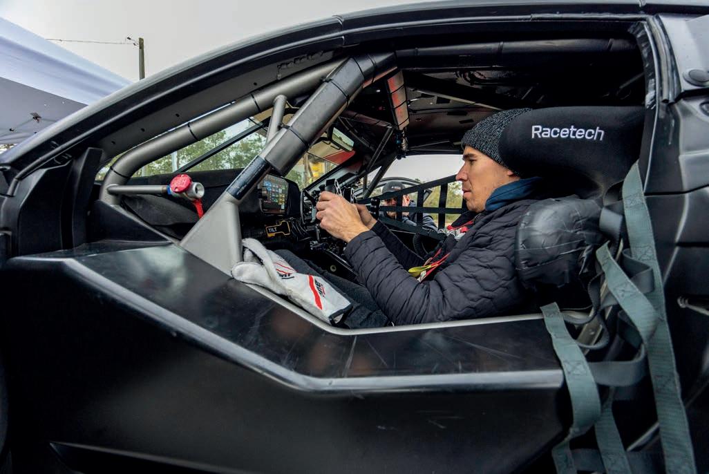
‘We’re using it as a brake-by-wire application, where his input from a rotary position sensor on the wheel is taking that input and converting the signal to the EBS modules, which are then generating the pressure on the axles.’
Despite the obvious complication of having two separate systems, it was actually easier to do that than to convert the entire car to brake-by-wire. The team would have required more parts, and the car would have had to be re-homologated, which would have taken time, money and additional effort. It would also have hampered the next step for the system, which is to introduce it to other cars.
‘We wanted to minimise the differences in the car for the able-body driver so they can go between cars and not feel any difference,’ explains Krell. ‘We also looked at the homologation process, and all the components you have to add. The more parts you change, the more complicated the homologation process becomes.
‘If we changed the pedal box to make it full brake-by-wire, that would add more components because we would have to include a pedal feel emulator for the able-body driver to try to match it. So we would be trying to match the hydraulic braking feel for Robbie by hand, and then we would have to do the same for the able-body driver with their foot brake.’
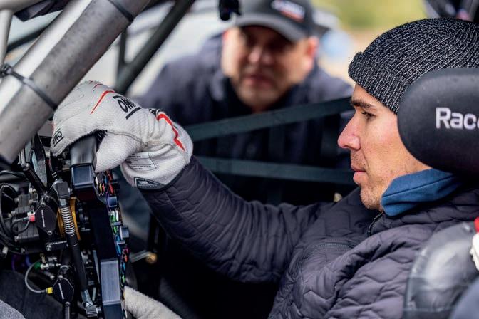
On the upside, this increases the chances of the system being used on other cars, for other drivers who may also require hand controls, which is a wider target for the Bosch engineers, and Wickens.
Despite the fact that both hydraulic and electronic systems are well understood and developed, the correlation between the two still needs to be fine tuned. To do so, Milner tested the car at The FIRM (Florida International Rally and Motorsport) prior to the Long Beach race. During the test, Milner tried using the hand controls and came to within a second of his own best lap time.
‘We wanted to minimise the differences in the car for the able-body driver so they can go between cars and not feel any difference’ Jordan Krell

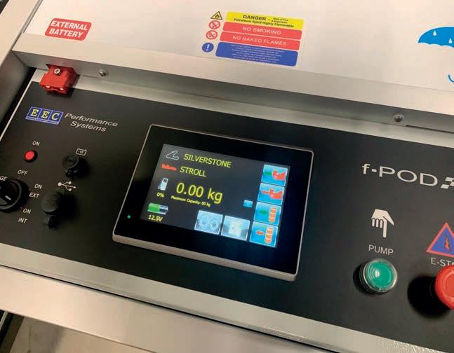
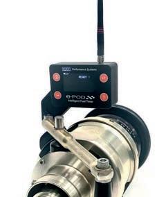


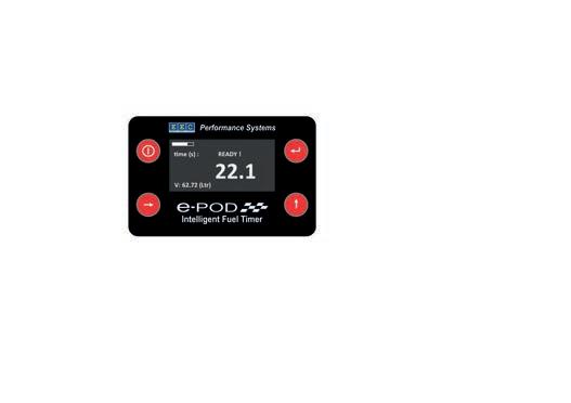


It is not only the braking system that needs to be tuned. Wickens also uses the paddles for throttle application, and this also needs to be set up. While braking is a priority, getting acceleration right is also key to generating good lap times, but that was easier said than done with the rear-wheeldrive Corvette.
‘You can look at the calibration on the sensors and the ECU, so that way he almost gets his own pedal map,’ says Krell. ‘We can look at the paddle itself, and how it is travelling. If the angle sweep needs to be a bit different, we can build that in mechanically.’
The braking system can, to a certain extent, be judged on ‘feel’, but throttle application is governed by the car’s traction control system. Oddly, given Wickens’ extensive motor racing career, he says he doesn’t have a lot of experience racing with traction control systems, so this is a steep learning curve for him.
‘Sometimes I’ll get snap oversteer, and accidentally lift off the throttle completely, which just bleeds loads of lap time,’ he says. ‘In terms of extracting lap time from a proper traction control system, with all the aids and assists we have inside the car, I’m still trying to understand what makes it click, because when I’m applying throttle, my resolution is not spot on yet. I think I’m applying 10 per cent throttle, but it’s actually more like 30, 35 or even 40 per cent, and I’m immediately getting traction control intervention.’
Wickens is having to learn that he doesn’t necessarily need to drive around problems. Much of the system can be tuned to his liking, as it is in the LMDh prototypes, and it is here that a few short cuts have been taken.
‘The module is the same one we are using with the LMDh car, the same part number,’ says Krell. ‘It also has very similar software so, when we calibrate them, we make sure the input we’re requesting is matching, and even compensating for, brake pad stiffness; we have the same personnel doing that.’
While others may look at a production car application for the system, more work needs to be done in racing before taking on that mammoth task. ‘There are a lot of pieces that have to go into a production car as it is a pretty different endeavour,’ admits Krell. ‘It’s quite different from motorsport when you look at it from a regulatory perspective. It’s something Bosch is definitely interested in, and we want to take the technology and learnings we have from Robbie, and we already have these components, but it’s not a ‘tomorrow’ endeavour.
‘When I look to the horizon, I see more how do we make this a system that’s not just for Robbie and Corvette? So really, the next step for us is making this a product a racecar
‘It was Bryan Herta Autosport [BHA] and Hyundai that got me back into the car. We were using a previous braking system that was purchased by Michael Johnson, who is also a paralysed racing driver. The whole thing came to fruition because of Bryan Herta and Sean Jones, co-owners of BHA, partly because they are just good human beings, and because Johnson and BHA had a hand control Hyundai Veloster N TCR car available for me to try in 2021.
‘It was an off-the shelf system, which was then modified and tuned for the needs of the Elantra N TCR. We used it throughout the 2022 season, but afterwards made changes to the pneumatic valving to improve the latency. It was basically a pneumatic actuator that pushed the able-body brake pedal down. I would apply pressure using the brake ring on the back of the steering wheel. When it reached a threshold pressure, it opened a valve and the pneumatic actuator would push the pedal the rest of the way down.
‘We were fortunate in the IMSA Challenge series that the fuel flow rate was pretty slow, but we still worked hard to make sure the team wasn’t waiting for the driver change if the car wasn’t taking on a full tank of fuel. We got the swap down to 20-25 seconds consistently.
What I want is a proper racecar brake pedal feel.
I have been seeking that hydraulic sensation with the hand controls
‘However, the driver opening was larger in the Hyundai TCR than it is in the Corvette GT3. The Corvette is a pretty tight cockpit. It’s like getting into a formula car, just through a door rather than over the top. There are some benefits, like the steering wheel tilting up out of the way, but the hardest part is getting my legs in the right position. The pedal box is deeper into the car, with a lot more leg protection than a TCR.
‘The latency would vary depending on how much pressure was in the pneumatic actuator. Worst case scenario, I would deal with seventh tenths of a second latency, best case three tenths.
‘The 24 Hours of Daytona was interesting, because braking for Turn 1 you have the whole straight and banking to build up enough pressure, so there it was the best case scenario. By Turn 3, however, it didn’t have enough time to recharge after the massive braking zone for Turn 1. I would tip into the brake softly, like you would on a road car, to understand what brake I had. If you try to just hammer the brake, and experience latency, you out brake yourself. With a slight brake, if it came on earlier than anticipated, I would lose less time.
driver can use and take with them, no matter which team they’re at, so they don’t have to rely on a team to engineer a bespoke solution just for them.
‘That’s why it has a separate keypad, because otherwise you’d require an integration with each GT3 manufacturer to change their keypad, and their rotary switch, to work with your system. Doing it this way, we can make it transferable from car to car.’
‘The damper over the steering wheel is like my master cylinder simulator. That’s what gives me the brake feel so it’s not a linear sensation. There is a little gas damper, which then has bump rubbers and packers. The spring is a 50lb/in spring, because what I want is a proper racecar brake pedal feel. I have been seeking that hydraulic brake sensation with the hand controls.
‘With the first generation of hand controls, it was almost the opposite. The brake pedal was very stiff and then, once the pneumatic actuator applied the brake, it was very soft, so it wasn’t a progressive force. Now we are getting it back to how I want to apply the brakes, with zero latency and the feel I always wanted.
‘The issue is that nothing comes for free with engineering. I don’t want to keep increasing the force, but I want to increase my brake feel on the first 20 per cent of travel. With springs, or anything that compresses, it gets stiffer with force, so it’s a very fine line we’re treading.’
For the 2025 season, then, Bosch and Wickens will work together to continue to develop the hand and system controls in this completely new environment. While Wickens primary goal is obviously to win more titles, Bosch will aim to help him in that but, at the same time, be looking at improving the user interface, in the hope of making its system more accessible to other teams and drivers who could benefit from it.


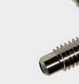


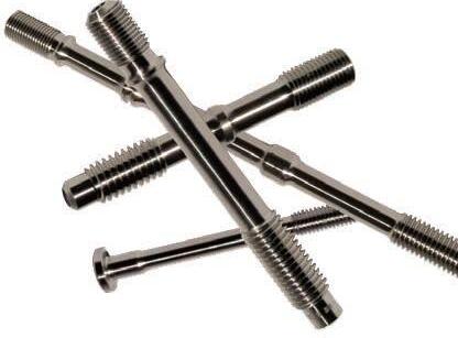


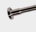

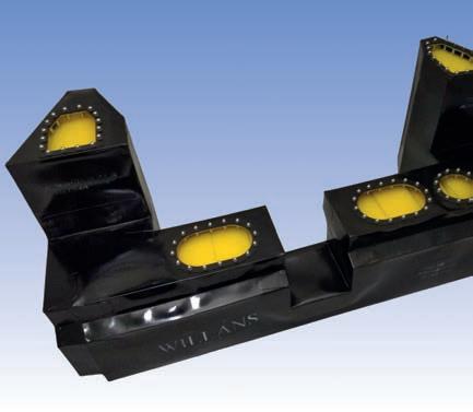

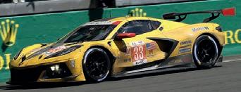


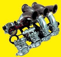
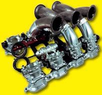


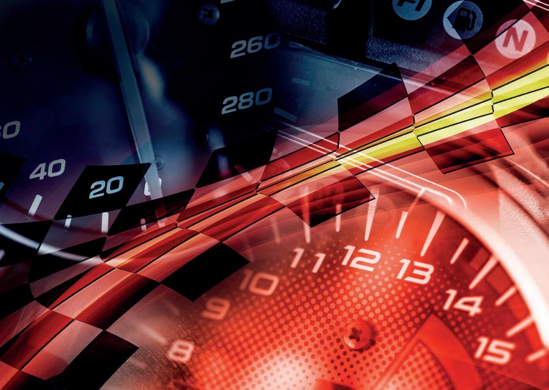

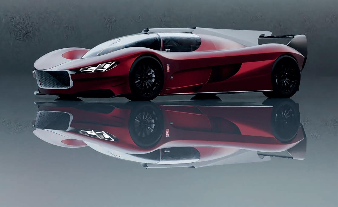
Liquid and gas are the hydrogen storage methods on everyone’s lips, but there may be an alternative solution to using the fuel safely. Racecar investigates
By ANDREW COTTON
It is well documented that burning hydrogen, either as a gas or a liquid, to power racecars produces minimal emissions at the tailpipe, and that the emissions that are produced are less harmful to the environment than those from fossil fuels. What is less clear is how to create that hydrogen, the environmental impact of doing so, and then storing it safely and cheaply in order to be able to use it in a vehicle.
Even ignoring all the impact of creating hydrogen in the first place, storing it as a gas in a chamber suitable for cars requires extreme levels of pressure, which then need to be contained. Put a high-pressure gas tank in a racecar and immediately there are some obvious concerns. Hang any such tanks outside the crash structure and there will be more questions than answers.
On the other hand, if you put hydrogen into a racecar in liquid form, it has to be cooled to around -253degC, which comes with its own challenges, both in storage and delivery of fuel to the power unit.
The Automobile Club de l’Ouest (ACO), which organises the 24 Hours of Le Mans, is working on its third iteration of laboratory car to test and demonstrate hydrogen technology. While the ACO has invested in gas storage in the past, it is now following the
FIA’s direction for circuit racing and will convert the H24EVO to run on liquid hydrogen. This has made it seem like there are only two solutions to the hydrogen storage problem, yet there are other potential options coming to light.
Ian Dawson, who ran a pioneering diesel car at Le Mans with backing from Caterpillar in 2004, using a VW Touareg engine in a Lola chassis two years before Audi started its famous project with the fuel, is working to integrate a solid-state hydrogen storage system into a racecar, with hopes it will one day lead to a one-make series.
The idea started nearly 10 years ago, when it dawned on Dawson that he was not enjoying modern day motor racing. With development limited, there was very little innovation he could do on the car he was
‘I stumbled across a project in Austin University where the professor said to me that I didn’t want high pressure, I needed low pressure hydrogen’
Ian Dawson, CEO at Dawson Racing
running in an American series, so he decided to either stop altogether, or build his own car, but with new technology.
He opted for the latter and started to look at alternative fuel solutions, eventually settling on hydrogen. His path to creating a car was given a boost by a link with Chevron Ventures, which allowed him the luxury of investigating the latest hydrogen technology.
‘I stumbled across a project in Austin University where the professor said to me that I didn’t want high pressure, I needed low pressure hydrogen,’ recalls Dawson.
To achieve this, he had to focus on solid state hydrogen cells. This is not new. Such cells were first developed in the 1950s, but the sector is evolving quickly and is now at a stage where a solid-state hydrogen system is more power dense than a lithium-ion battery.
With manufacturers like Toyota and Alpine developing their own hydrogen prototypes, Dawson faced a dilemma of where to fit his car in the racing spectrum. Then it was a race against time (and money) to have his system in a vehicle, ready for testing, and reliable.
Covid then put the development world on pause, although Dawson was able to continue some of his investigations and partnerships.
‘It’s a chemical absorption through something like a powder, a sponge process, which is very like taking a tennis ball and infusing it with hydrogen molecules’
Ian Dawson
Having made the decision to build a new car outside of any existing regulations, Dawson partnered with an expert in fuel stack technology, and other industry leaders, including Empel Systems. The decision was made to move the company back to the UK from Texas and set up Dawson Technologies Limited with Dawson and his son, Simon, mid2023, along with a small design team.
Key to the project is the hydrogen storage in the car. Dawson’s team locked into storage pouches filled with a sodium-based powder that produces hydrogen when wet. The team committed to work with Aich 2, a US company based in South Carolina and which has a programme in Scotland. The company has developed the pouches, which are sealed and dried as the powder is extremely sensitive when exposed to moisture.
Sodium borohydride is a crystalline powder. It is decomposed by water to form sodium hydroxide, a corrosive material, and hydrogen. It is, says Dawson, a safe, light and effective method to produce the gas: ‘It’s a chemical absorption through something like a powder, a sponge process, which is very like taking a tennis ball and infusing it with hydrogen molecules. It doesn’t need heating or cooling and it has three times the density of conventional hydrogen.’
As spent hydrogen naturally produces water as a by-product, gaining access to water is not difficult. Two other factors make this a more viable solution: one is that it is stored at low pressure, just 10bar, compared to 700bar for the gas form. The other is that its creation of hydrogen does not produce high temperatures. The fuel itself does therefore not need to be cooled to extreme temperatures, and there is no large change in pressure within a fuel cell from empty to full, which is another source of heat generation.
The hydrogen is then used in a fuel stack, each one capable of producing up to 220kW of power per stack. Dawson believes around 30kg of sodium borohydride will be required to power his car for two hours.
The system he has developed has low pressure drop, which means it is not susceptible to overheating from the
Fuel cell electric vehicle with safe solid state hydrogen storage
chemical reaction required to produce the hydrogen gas, and it can run on either pure hydrogen or reformate gas.
Once created, the hydrogen gas is fed into the stack, which then delivers power to a supercapacitor hybrid system. This is similar technology to that used by Toyota at the start of the LMP1 hybrid era with its TS030. Much as the current Hypercars balance electrical and combustion power to a maximum of 520kW, so complicated electronics manage power delivery from the supercapacitor battery and hydrogen cell.
Fitted to the rear wheels only are in-wheel motors that can deliver a maximum of 580kW, but which normally run closer to 300kW. ‘The peak average is around 300kW of energy, and
there are periods when you are probably going to have to ease out the throttle, just like in a fuel formula from years ago,’ says Dawson.
Indications are that the car would lap Silverstone in a time similar to a current GT3 and would be able to do so for at least two hours. After that, the pouches would need to be cleaned out of the residue powder. At that point, they could either be replenished with new powder, or replaced. Dawson says the ‘pit stop’ would take approximately four minutes currently, if the car were to race. By which point the GT3 would have lapped it twice.
‘It must be credible,’ says Dawson of the car, and the technology. ‘To do that, the car has to have the same wheelbase, same weight and same aero and mechanical balance as a GT or LMP car or you can’t put the right size tyre on it, and get the tyre heat into it.
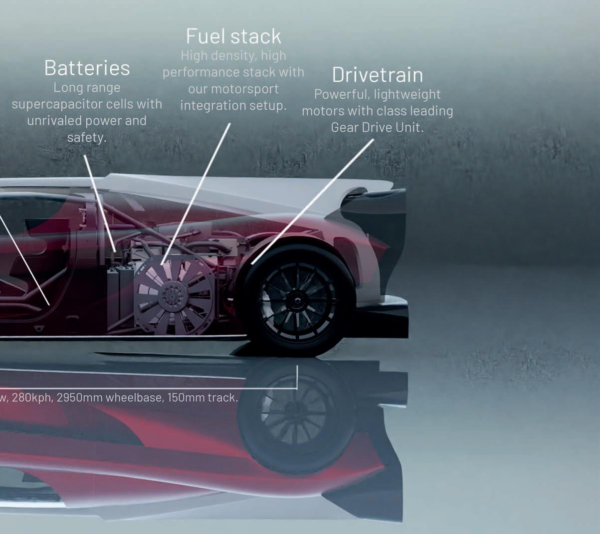

H
H
User
Operational
Input

Solid-state batteries were first developed in the 1950s, using silver-ion conducting electrolytes. The batteries had high internal resistance, while cell voltage and energy density were low. Over the next 40 years, the technology advanced, and a solidstate battery was incorporated with a thin film, lithium-ion battery. Further advances have seen solid-state batteries improve in both power density and reliability, but there is still some way to go before they can be mass produced.
A solid-state battery is one that uses a solid electrolyte instead of a liquid electrolyte, which is what is used in lithium-ion technology. Lithium-ion batteries use a polymer separator between the anode and cathode, which works as an insulator and allows the lithium ions to move through it.
In a solid-state battery, the cell is very different. While the cathode can be made of the same compounds as found in a lithium-ion battery, the separator is solid and also works as the electrolyte. The anode, meanwhile, is made of lithium metal. This is safer, increases energy density and extends the overall lifespan of the battery.
However, solid-state batteries do have their downsides. With a solid barrier between the anode and cathode, it can be subject to puncture by the solid mass dendrites that are produced as the battery degrades over time and use. The lithium ions move through the solid electrolyte by pathways between, or through, defects in
‘Some of the technology we’re doing, nobody’s ever done it. There is no existing system. We’ve got a company to write algorithm programs that predict what can happen. They’re doing it with information they’ve never had before, but they’ve been quite surprised, saying this is a game changer and we can store a hell of a lot of hydrogen.’
The car itself is being built with flax fibres, including hemp. It uses a Hewland transmission, AP Racing brakes and is based
‘Some of the technology we’re doing, nobody’s ever done it. There is no existing system’
Ian Dawson
the crystal lattice structure. Without the graphite intercalation anode, the cell is more compact, providing higher cell and module level energy density. With high limits of thermal operation for the solid electrolyte, solid-state batteries may require less thermal management. If dendrite growth can then also be suppressed, it may be possible to fast charge batteries at higher rates, with proposed charge times of 15 minutes or less.
If having an inert powder held in normal storage conditions sounds too good to be true, you might wonder why motor racing authorities have decided to focus solely on liquid storage. The answer is that the transformation from powder to gas is rather tricky to manage. There are a few ways of doing it: one is to use alkali metals, such as sodium, potassium and lithium, which are fairly potent when mixed with water. Another is to use alkaline earth metals, such as calcium, magnesium and barium, which react more slowly with water compared to alkali metals, but still produce a gas. A third way is to use metal hydrides; compounds of metals with hydrogen that can produce the gas. A fourth method is to use hydrazine compounds that can react with water under specific conditions.
The problem is all these processes create significant thermal energy and are prone to runaway, where the rising temperature attracts oxygen that then feeds the fire.
loosely on an LMP3 car crossed with a GT car. There is, reasons Dawson, not much point building a prototype to compete against the likes of Toyota, nor a production-style GT3 as there is no logical place to race it. What has been produced, then, is a rollcage that is certified by the FIA, front and rear clips much like those of the Ferrari 296 GT3, and a hydrogen storage mechanism.
Unfortunately, as it is not in keeping with the FIA’s mandate of liquid storage in all of its racing activities, and so there is a target to race at events such as Pikes Peak, which sits
outside of the FIA’s remit and requires only safety assurances to allow concepts to run.
Much of the development behind it will likely benefit the marine and aerospace industries, so the car is really a proof of concept that may evolve into a one-make series if it can be shown to work in a hostile environment such as a racing car.
For the time being, the concept is demonstrating an alternative way of storing hydrogen, in a clean, safe environment, without the extremes of temperature and pressure traditionally associated with it.
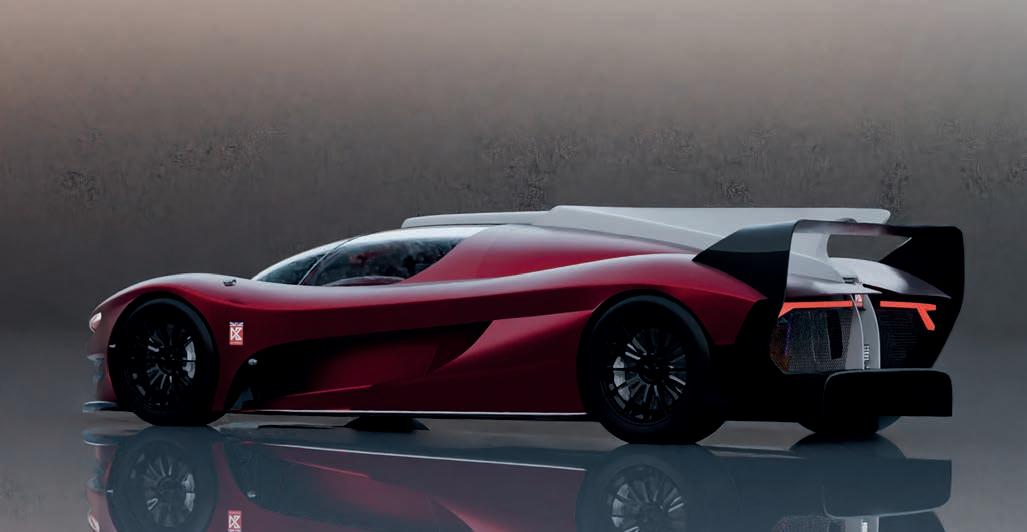


After last year’s big reset, progress is being made on the future of the LMP2 class as guidelines for the new cars are laid out
By DANIEL LLOYD
At last year’s 24 Hours of Le Mans, organisers in charge of the LMP2 sportscar formula announced plans to tear up original plans and contracts and instead introduce a new generation of car in 2028. Crucially, this signified the abandonment of the previous plan to base future LMP2s on the current LMDh architecture. The announcement effectively wiped the slate clean, putting planning on the new rule set back to square one. It also ensured the current cars, which made their debut in 2017, will reach a decade old before being replaced.
Fast forward to now, and the blank canvas of the 2028 technical blueprint is starting to be filled in. In March, the FIA invited companies to tender for contracts to supply the spec engine, transmission and electronics package, as well as the chassis.
The documents confirmed the preferences of the rule makers, chief among them a small capacity, turbocharged engine, and a halving of the number of licenced chassis constructors. While the current LMP2 cars had to be de-tuned and compromised when LMP1 was replaced with the slower Hypercar class in 2021, there is now an opportunity to design something that fits in from the start.
LMP2 currently allows four companies to build chassis: ORECA, Ligier, Dallara and Multimatic. From 2028, a maximum of two will be permitted. It doesn’t quite go as far as the paddock rumour at Le Mans last year that LMP2 would have a spec chassis, but it moves in the same direction.
The success of the four constructors varied wildly, with ORECA producing hundreds of
chassis while the others had far fewer customers. It has been clear, with LMP2 being removed from the World Endurance Championship, that the market will be smaller than it was in 2017, although the popularity of the class remains stubbornly high.
The chassis tender document states the 2028 LMP2 car will be 4750mm long, similar to current spec, up to 2000mm wide, 100mm wider than before, and up to 1050mm tall. The driver will sit centrally, a big departure from current LMP2 cars. They will be 50kg heavier, based on the target minimum weight of 980kg. The fuel tank capacity should be between 75 and 80 litres; the former figure being what the rule makers have stipulated at Le Mans in recent years.
For bodywork, the FIA and ACO have requested a ‘lasting modern design maintaining endurance racing’s heritage.’
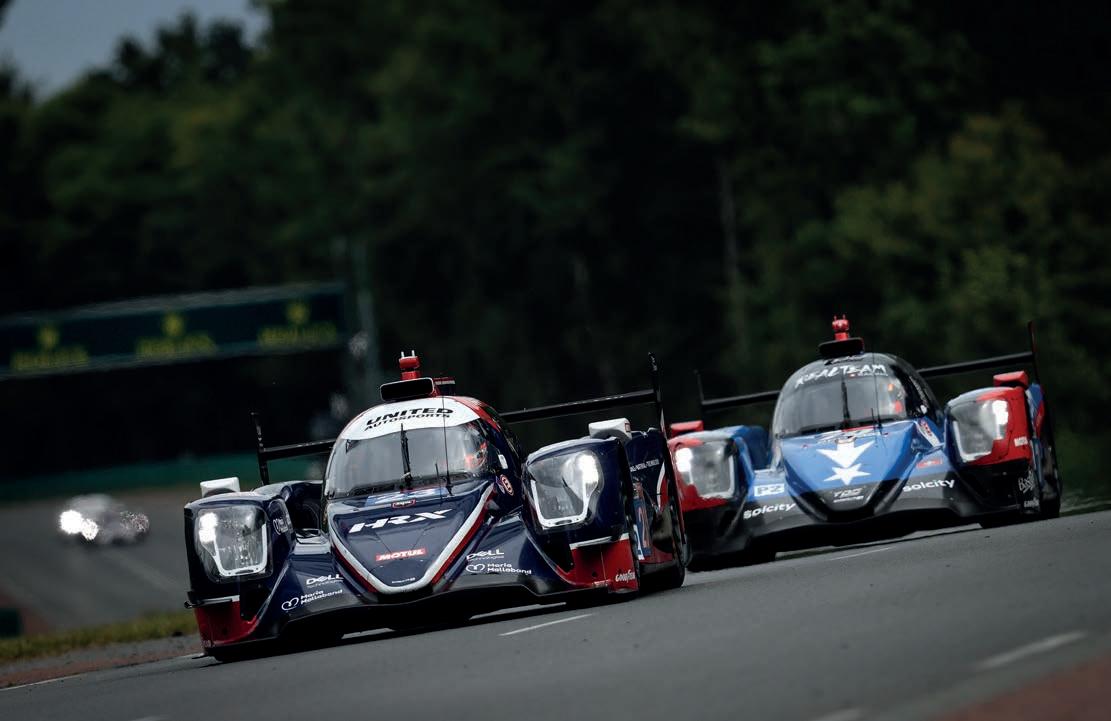
The documents confirmed the preferences of the rule makers, chief among them a small capacity, turbocharged engine, and a halving of the number of licenced chassis constructors
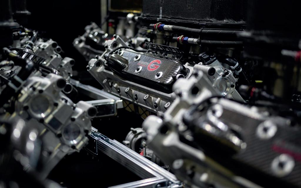
The current LMP2 V8 engine produces up to 450kW (600bhp), although in practice it is less than that, based on series requirements. The 2028 engine power target is 420kW
The suspension guidelines include a double wishbone with pushrod arrangement, one side damper per wheel but no heave damper, a new driver-adjustable anti-roll bar and three options for suspension kinematic adjustment. On the brakes, six-piston aluminium calipers are preferred, while the 18in wheel diameter remains unchanged.
The prospect of LMP2 becoming turbocharged was the big takeaway from the powertrain and electronics tender. Although it didn’t state naturally aspirated engines are banned, the preference is clear. This is significant, considering all cars in the class have used the same 4.2-litre, naturally aspirated V8 from Gibson Technology since the British company was awarded the 2017 regulations’ supply contract. That engine surpassed five million kilometres last September and its wasp-like note is the distinctive soundtrack to LMP2.
There are multiple reasons why the FIA and ACO are interested in ditching naturally aspirated power. One is to bring LMP2 more in line with the road car industry. Small turbo engines have become popular in new internal combustion vehicles, and this is something the sportscar governing bodies are keen to replicate on track. Efficiency is another driving force, and a section in the tender stating the FIA and ACO’s preference for a small capacity engine helps fulfil that.
A turbo engine also comes with boost pressure that can be regulated equalise performance. Currently, air restrictors are
used. A further tick in the box is that a turbo would reduce noise, making LMP2 more suitable for circuits with decibel restrictions. LMP2 moving away from naturally aspirated power is perhaps not surprising. The desire for greater efficiency was central to the ACO’s decision to equip the junior LMP3 formula with a turbocharged engine starting this year, having used a rumbling Nissan V8 since its inception. However, going turbo would still be a shock to the system for LMP2 teams that have become well acquainted with running a certain type of powertrain.
It is also an interesting development for Gibson, which has long championed naturally aspirated power and was awarded the tender to supply a 4.2-litre V8 from 2026 to 2030 before the blueprint was reset. A senior source at the supplier said the company was ‘digesting’ the details of the tender documents. Gibson appears to have seen the FIA and ACO’s stance coming, but it’s too early for it, and other engine manufacturers, to comment on their plans for the 2028 tender.
In addition to stating the preferred basic engine layout, the tender documents also identify a maximum power output of 420kW (563bhp) measured at 1010mbar atmospheric pressure and 20degC ambient temperature. This would then need to be adjustable to 380kW (509.5bhp), depending on championship-specific requirements. For reference, the current Gibson V8 can produce up to 450kW (600bhp).
The reason for a wide potential horsepower range is because LMP2 needs to be adaptable; its place on the grid differs from series to series
The reason for a wide potential horsepower range is because LMP2 needs to be adaptable; its place on the grid differs from series to series. At the 24 Hours of Le Mans, for example, it is the second quickest class, so its performance relative to Hypercar needs to be considered for safety and sporting reasons. This is less of a headache in the European and Asian Le Mans Series, where LMP2 is top dog, although the class below it there is LMP3, which is slightly faster than the LMGT3s that sit behind it at Le Mans.
The FIA and ACO expect the 2028 cars to hit a top speed of 315km/h at Le Mans. The figure last year was 325.8km/h, while in 2020 (before the LMP2 cars were slowed) it was as high as 338.1km/h. According to the chassis tender, an aerodynamic device will be permitted on the rear wing.
The 2028 tender proposes a maximum engine weight of 160kg, around 25kg more than the current unit. A target maximum brake specific fuel consumption of 250g/kWh has been stated. Direct injection is preferred,
The winners… will be confirmed on 10 June, teeing up the possibility of an announcement at Le Mans
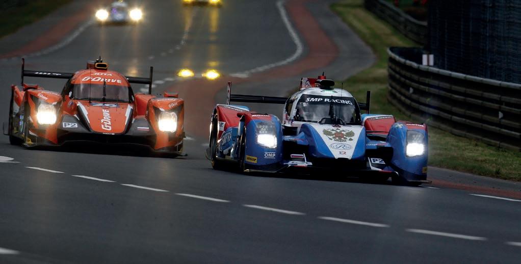
as is dry sump lubrication, with pumps mechanically driven by the engine. Further details include the air filter being located centrally on top of the engine and the exhausts exiting at the rear.
Engines must also be leased to teams for no more than €1500 (approx. $1625) per running hour. A €450,000 (approx. $490,000) target price for the car has been proposed.
On the transmission side, the organisers are looking for a six-speed sequential with a unique ratio gear set and three-stage reduction, consisting of an input bevel, cluster and final drive. The casing must be magnesium or aluminium, with overall weight no more than 85kg. Electronic and pneumatic gearshift actuators will be considered.
The transmission should have a mechanical limited slip differential with no external pre-load adjustment and a single specification of friction faces.
Both the transmission and engine must be capable of doing 14,000km, or 80 hours, before servicing. In terms of costs, applicants may specify whether they would prefer teams lease or buy the gearbox.
A single contract covers the powertrain, electronics and transmission tender. This means that, in simple terms, an engine builder, an electronics company and a gearbox manufacturer would need to work together to file an application. Previously, the transmission supply was part of the chassis tender, which explains why it was possible for the four licenced chassis manufacturers to have different gearboxes. In reality, three chose the Xtrac six-speed sequential unit, leaving just the Ligier JS P217 Gibson running a Hewland TLS-200 ’box. That variety will no longer be possible when
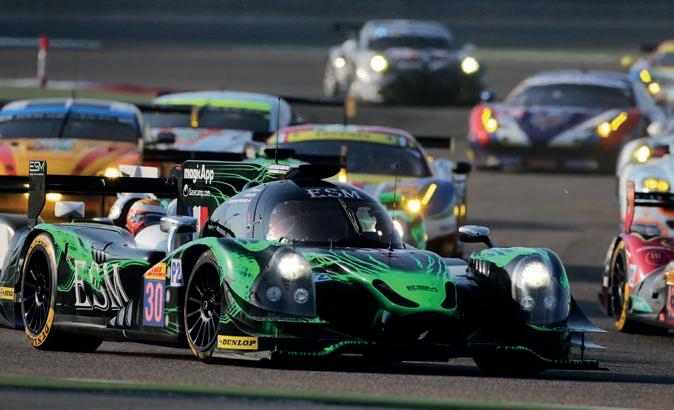
everybody is using a common engine that is contractually tied to a specific gearbox.
The electronics side of the tender covers a range of parts, including the ECU and data logger, steering wheel, wiring loom, vehicle and engine sensors, control sensors and the switch panel. Integrating the electronics into the same tender as the engine is new for 2028. The tender documents state the ECU must have 48 analogue and 12 digital inputs. Its injectors should have up to eight internal ignition and injection drivers. Teams will be able to access the ECU for data logging and telemetry purposes, while a separate configuration will enable the FIA and ACO to also use it for their monitoring needs.
The engine, transmission and electronics tender will be valid for five seasons, starting in 2028 and concluding at the end of 2032. Applicants need to submit information on a range of criteria, including technical, commercial, sustainability and marketing. Companies interested in supplying their powertrain and electronics technology have until 30 April to make their pitches. For the chassis, the deadline is 9 May. The winners of both will be confirmed on 10 June, teeing up the possibility of an announcement at Le Mans 2025.
LMP2 is a venerable category, having made its Le Mans debut in 2004 as an evolution of LMP675. The ACO continually reiterates its importance to the endurance racing pyramid, both as a feeder to Hypercar and as a headline category in regional series. The announcement last summer that the technical rules would be reset invited plenty of questions. Some are now being answered, and the fog is slowly starting to clear.


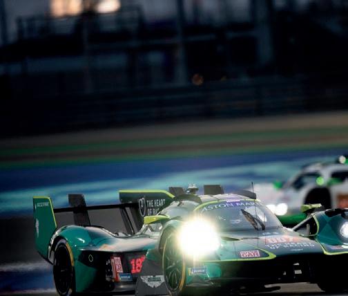


The FIA Foundation has funded a safety initiative to help prevent spinal injuries in rally raid events
By RACECAR STAFF
Bouncing over the sand dunes in Saudi Arabia on the 2025 Dakar Rally, Dacia Sandrider crews were testing in real-world conditions a new FIA safety initiative designed to prevent back injuries following heavy vertical impacts. Crews have, in the past, faced signi cant load and injury from the shock transmitted through the car and into the occupants during heavy, or sudden, impacts. Consequently, the FIA has invested in research to improve driver safety in o -road competition.
Attaching seat attenuators to racecar seats is not a new idea. The University of Turin conducted a similar study in 2010 on a Formula Student car that complies to the 2008 regulations, with positive results. However, in the latest study, the FIA has taken real-world data and applied it in simulation to produce this improved safety feature.

The basis for the study was the FIA Foundation, which co-funded a research project looking at preventing competitors from su ering spinal injuries. The aim was to nd a way to mitigate the consequences of heavy landings, which cause compressive loads to be transferred to the occupants’ spine. As part of the motorsport safety technical research programme, the FIA undertook the project with a number of key stakeholders, and began real-world testing in 2024, with immediately positive results.
Using data from incidents involving a heavy landing, which are recorded in the FIA’s World Accident Database, experts de ned a representative ‘severe crash pulse’ of 40g, orientated at an angle of 58 degrees from the horizontal axis, as a target for the project to mitigate against.
Experts de ned a representative ‘severe crash pulse’ of 40g, orientated at an angle of 58 degrees from the horizontal axis, as a target for the project to mitigate against


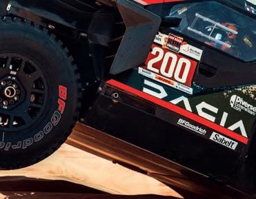

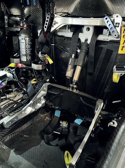


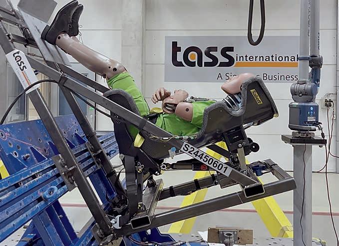
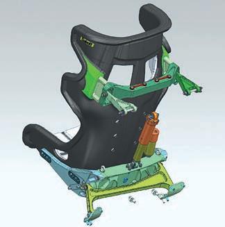
The impact damping mechanism was then developed to work in concert with that design of seat
This crash pulse was then used in simulations to de ne the best force displacement characteristics for a seat installed in competition cars so a dampening mechanism could then be developed and connected to it. The damper needed to reduce the impact transferred to the crew, but also not produce a sharp shock at the end of its travel, which could increase the load through the bodies of the crew.
Following re nement through simulation, an optimal design for the impact damper was manufactured and underwent laboratory testing, which con rmed it o ered around a 50 per cent reduction in forces transferred from the car to the occupants during the designated impact.
‘The success of this project has been fundamentally supported by the use of numerical simulation with virtual test dummies, to de ne the optimal characteristics of the attenuation system,’ said FIA senior research engineer – CAE manager, Paolo Panichelli. ‘It is a perfect example of how
The use of numerical simulation and virtual test dummies allowed the development team to de ne the optimal characteristics of the attenuation system
‘To provide such a big improvement in protection against possible spinal injuries is something very important for the competitors’
Xavier
Mestelan Pinon, chief technical
and safety
o cer at the FIA
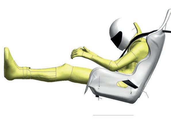
[simulation] allows for the development of a speci c product without the need for extensive experimental campaigns.’
The next step in the project saw the FIA supporting British company, Prodrive, which built the Dacia Sandriders used in the 2025 Dakar Rally, to develop a suspended seat, connected to the rollcage via the new damper. This was rst implemented on the 2024 Rallye du Maroc, and monitoring data throughout the real-world testing phase showed the device to be operating as expected, and delivering signi cant comfort, and safety, bene ts.
The FIA seat attenuator is now in use in the Dacia Sandriders, and will be mandated in all new T1+ vehicles in the FIA World Rally-Raid Championship from 2027.
‘The seat attenuator project is something we are very proud of,’ says FIA chief technical and safety o cer, Xavier Mestelan Pinon. ‘It is a really signi cant step in terms of safety in

the W2RC, where the cars and crews compete in some of the most extreme conditions in the world. To provide such a big improvement in protection against possible spinal injuries is something very important for the competitors, and it is projects such as this that the FIA, with the support of the FIA Foundation, will keep investing in across all our championships.’
FIA head of research and vehicle safety, Marco Petrilli, echoes this sentiment, adding: ‘This has been a really fantastic project to bring to the W2RC. We are driven by the data, and we identi ed this as an area where we could bring some signi cant bene ts for the crews. Using the FIA World Accident Database, we could de ne what a typical high-impact landing that can cause a spinal injury looks like, and use that information to set our targets for the seat attenuator, and from there set requirements for a device according to our extensive simulations.’
This is just the latest example of the FIA’s ongoing commitment to improving safety in all aspects of motorsport.

By DANNY NOWLAN
ne of the key ingredients that added to the anticipation of the 2015 24 Hours of Le Mans was the debut of the front-wheel-drive Nissan GT-R LM Nismo. A lot was written about this LMP1 car going into the event, which took place at a time when you could do some really exciting things with sportscars that both made sense and added performance. Ultimately, the unique-looking Nissan did not live up to the hype but, as we all learn more through our mistakes than successes, it deserves to be both remembered and celebrated.
In the lead up to the 2015 race, there was a lot of internal optimism about the car. The consensus was it would do really well, and I admit I was very enthused by the potential of its design. However, its best qualifying lap time of 3m36.995s was trounced by Porsche, Audi, Toyota and even the privateers. The race was not much better. Only one Nissan reached the end, but didn’t do enough laps to be classified.
As the 10th anniversary of the car’s only race nears, here is my take on what went wrong and, more importantly, how it could have been fixed. I would also add that there are some really good lessons that could be built on if this were ever to be tried again.
Before we begin, let me state that I do not intend to re-write history. One of my pet peeves these days is how, when things go wrong, everyone goes into arse covering mode and refuses to take responsibility. For the record, I stand by every word I stated in my original article at the time. There are some strokes of genius in this car and it is a project that deserves to be completed.
Ultimately, the two factors that let the Nissan down were its front weight distribution of 66 per cent, and its lack of rear-wheel drive KERS / hybrid discharge. I’ll admit here that the first factor was an oversight in my first article, and I should have been more on the ball with that. In fairness, though, I was focusing more on the potential of the design.
The second factor was the equivalent of going into a gun fight with a laptop. When I arrived at Le Mans and the Nissan engineers told me this, I just shook my head, thinking you guys are going to have a rough week. We’ll explore both elements in detail here.
Before we do any simulation, though, let’s look at some numbers at a weight distribution of 66 per cent. To illustrate this, we’ll consider some basic car parameters. For effect, I’m going to trim the weight from 1000kg to 900kg. This is not a random figure; you’ll see why I’ve done this shortly.
The figures are shown in table 1. For the record, the peak lateral and longitudinal g has been taken from customer LMP1 data.
Before we do anything, it is clear the front tyres are going to get a workout. Where things get interesting is when you take into account load transfer. Working this out for each corner weight, we have that shown by equation 2. (2)
Here, prr is the lateral load transfer distribution at the front, LTax is the load transfer due to longitudinal acceleration and LTayf and LTayr are the load transfers due to lateral acceleration for the front and rear respectively. Crunching the numbers, we see the results shown in table 3
Table 3: Load transfer loads as corner weight
Let’s now have a look at how the corner weights vary from static conditions to a speed of 120km/h and 220km/h, which are typical cornering speeds at Le Mans. These were calculated using that shown in equation 1
Here, wd is the relevant weight distribution and V is in m/s. I’m also assuming the aero distribution is the same as the weight distribution. The corner weight results are presented in table 2.
This analysis shows very clearly that the central problem here is the front tyres are taking far too much load. This is as clear as a bell from looking at tables 2 and 3
Firstly, in a high-speed corner, we could potentially be looking at a front load of 900kg, though in practice you would run less front lateral load transfer. Most likely, this would be in the order of 50 per cent. However, this raises another problem. As we shift the lateral load transfer to the rear, we start unloading the inside rear tyre. Do you really want to be doing that in the middle of the Porsche Curves?
The other case to consider is braking into a low-speed corner. If we look at the 120km/h case, the rear tyres are very lightly loaded; they would be carrying just 70kgf. You don’t have to be a rocket scientist to see you are painting yourself into a few corners here.
As we shift the lateral load transfer to the rear, we start unloading the inside rear tyre
A graphic illustration of this is shown in figure 1. Note the inside rear wheel lifting clean off the track mid-corner. Also very sobering to consider here is that we haven’t taken into account any bumps yet, and have deliberately underestimated car weight.
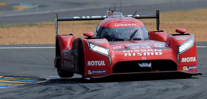
If you want to put all this into perspective, run the numbers for a rear-wheel-drive car with a 45 per cent front weight distribution. We’ll return to this theme shortly.
Some might counter this by saying that in a rear-wheel-drive car the front unloads as well. However, there is one fundamental di erence here. With a mid-engined, rear-wheel-drive car, the front provides the steering input and the rear provides traction. So, as the load shifts to the rear, we get stability and the ability to put the power down. In a front-wheel-drive car, in addition to taking the steering input, we are also asking the front tyres to provide traction. In addition, typically we will unload the inside rear tyre as well. In an extreme weight distribution situation, this is not good.
The simulation results re ect the situation we saw in our hand calculations. For a front weight distribution of 66 per cent and frontwheel drive, with the KERS turned o , the lap time was 3m37.8s. Our baseline RWD LMP1 car with no KERS ran 3m33.7s. The reason we have lost so much time is illustrated in figure 2.
The rear-wheel drive baseline is coloured and the front-wheel drive, 66 per cent front weight distribution case is shown in black.
While the steering hasn’t massively increased (since ChassisSim is driving to the grip) the damage is done at mid-corner to turn exit. The standard LMP1 car was at 142km/h, while the 66 per cent, frontwheel-drive Nissan was at 135km/h. This was re ected in the turn exit condition as well, where the speed was down by 10km/h.
Having engineered a high-powered, high-downforce, front-wheel-drive car, I’ve seen this in actual data and, if I’m honest, I was expecting the simulation results with the Nissan to be a lot worse. Nissan personnel will counter this by saying we have tyres custom made for us, but there are two problems here. Firstly, Michelin has a lot of experience building
This analysis shows very clearly that the central problem is the front tyres are taking far too much load
tyres that can carry 55 per cent of the load distribution of an LMP1 car, yet you have just asked the company to up this to 66 per cent. In doing that, you are asking the tyres to put up with at least another 100kgf of load and produce the same coe cient of friction. I’m no tyre construction expert, but I wonder if this is a bridge too far? Michelin is probably the only tyre company I know that could even attempt this, but then you are putting everything into the hands of a third party. Even assuming it were to succeed, the company’s RWD customers at the other LMP1 constructors would have every right to raise holy hell.
The other thing that undid things for Nissan was the limitation placed on its KERS. Just before Le Mans 2015, the energy recovery of the GT-R LM Nismo was downgraded from 8MJ to 2MJ. Despite the weight penalty incurred with KERS tted, that is going to hurt, as you’ve e ectively just cut your push-to-pass potential by a factor of four. To put this into perspective, even with a KERS discharge limit of 80kW, it works out in the order of 80Nm extra engine torque. To have that constrained is going to have a devastating e ect. However, the real killer here was not having the KERS discharging at the rear. This meant the Nissan LMP1 car lost the e ective all-wheel-drive capability the design was supposed to o er. To remind us all of what the Nissan team didn’t have, let me present the potential of what could have been available. Looking at the sim results of the weight distribution at 60 per cent that we performed in the previous article, one of the channels that ChassisSim returns is the maximum longitudinal force available from all four wheels. Looking at the rear tyres, we see that shown by figure 3.

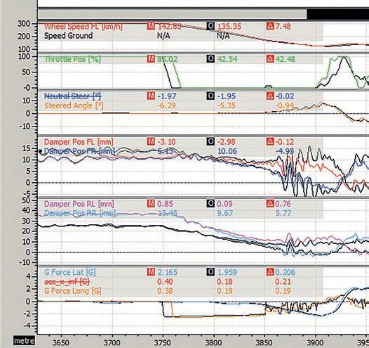
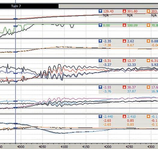


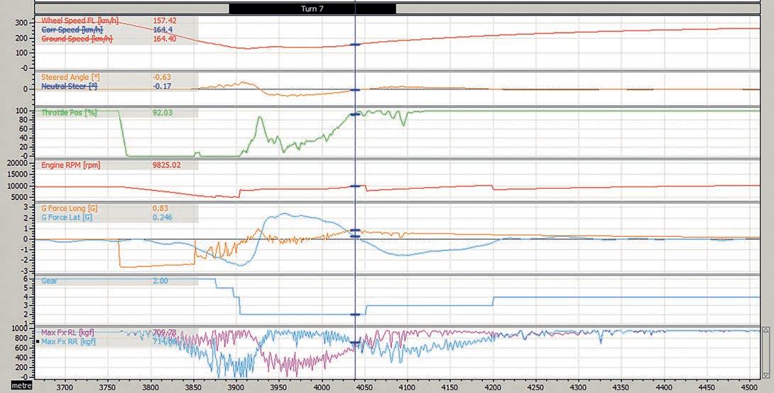
I draw your attention here to the bottom traces, which show the available longitudinal force at turn exit. At a speed of 157km/h, we have an available longitudinal force of 710kgf per rear tyre. In terms of available power, that can be expressed using equation 3
What this means is we have a potential of 606kW on tap at the rear, although in reality it will be much less because the rear tyres have to corner as well. Let’s just say for the sake of argument that you have 300kW of useable power at the rear tyres. What this means is KERS, when used the right way, effectively gives a turbo boost. When you are competing against well-sorted opposition like Audi, Porsche and Toyota you just can’t afford to give away that sort of advantage.
The good news is that not only is this fixable, should the car ever be miraculously re-born, but we’re about to find out what could fix it.
Now, don’t be surprised to see the weight distribution move back to 60 per cent. This is for three reasons. Firstly, the tyre loads shown in tables 1 to 3. We have already seen how, at 66 per cent front weight distribution, we’ve put ourselves in a corner. Run the numbers at 60 per cent and you’ll see the situation is immediately healthier. Backing this up, our sim results from the last article showed the car’s performance at 60 per cent was comparable to the rear-wheel drive LMP1 car.
The second reason is that at 60 per cent front weight distribution, you’re giving the tyre manufacturer a more straightforward job.
Now you are only asking Michelin to come up with tyres working at maybe 50-100kgf extra. This is more reasonable, and the other marques wouldn’t have cause to complain.
The third reason is energy recovery. At the time, hybrid / KERS worked by taking the available tyre force at the rear of the car and using that to store the hybrid energy. Winding the tape forward to now, with both front and rear axle regeneration, you can be a lot more flexible about what you do with your energy.
Granted, there are still significant issues with energy recovery, but they can be somewhat mitigated. Current F1 and LMDh cars are good cases in point here. With more weight at the rear of the car, two things are going to happen. You’ll be able to charge more since you have more tyre load, and also discharge more energy since you have more load at the rear to put the power down. As we saw in the analysis in figure 2, you have effectively opened up the potential of transmitting 300kW at the rear for a front weight distribution of 60 per cent. This is effectively all-wheel drive for free.
The other change I would make is to shift the car to an electric energy recovery system. In 2015, the Nissan GT-R LM Nismo was using the mechanical Flybrid system (I’d like to take the opportunity to give a shout out to the great crew at Flybrid. The system worked really well and they were instrumental in getting KERS / hybrid into ChassisSim, and that should be acknowledged). However, the electrical hybrid system did catch up and, particularly for the Nissan LMP1 application, it offered / offers significant advantages.
The primary reason for going electrical is that you can use the batteries as ballast for a chassis tuning device. To recall some
calculations from my previous article, let’s calculate a c of g limit based on the assumptions shown in table 4
Table 4: Limit calculation numbers
Parameter Mass xlocation
Car without battery 850kg1.2m
Battery pack 150kg3m
The xlocation is measured from the front axle. Here, we are assuming a weight distribution of 60 per cent on the front axle without a battery pack. Calculating the c of g location longitudinally, we see that shown by equation 4: (4)
As can be seen, the c of g limit is 51 per cent. I’ll admit this is an extreme case, but it shows you have flexibility in fine tuning where you want the c of g.
In closing, the downfall of the Nissan GT-R LM Nismo was its forward c of g distribution and its lack of rear-wheel drive KERS / hybrid discharge. Having seen this car up close, I still maintain there are some strokes of genius in it, and have no doubt that with the c of g shifted further backwards to 60 per cent, and the rear-wheel drive hybrid sorted, this car would have turned into a speeding bullet. Perhaps it’s time to re-visit the concept?


Egginton, 51, started out as a junior design engineer for Tyrrell in 1996 before stints with Xtrac, Opel and Aston Martin Racing led to a long F1 career with the Faenza-based tam
Racing Bulls Formula 1 technical director, Jody Egginton, has left the team to become the engineering director at Red Bull Advanced Technologies (RBAT).
The British engineer joined Racing Bulls, then known as Toro Rosso, in 2014 as its head of vehicle performance, before rising through the ranks to technical director in 2019. Prior to his long tenure with the Italian team, Egginton worked at the Silverstone F1 team facility for a sequence of occupants, including Midland, Spyker, Force India and Lotus.
Racing Bulls has not yet named a replacement technical director, but Egginton’s role will be covered in the interim by chief technical officer, Tim Goss, deputy technical director, Guillaume Cattelani, and head of car design, Andrea Landi.
‘Being part of this team for over 10 years has been a fantastic experience for me, providing some very memorable moments,’ said Egginton. ‘But after almost 20 years of focusing solely on Formula 1, I feel it’s time for a change. I will have a great remit as engineering director of Red Bull Advanced Technologies and the company currently has an exciting list of projects, so I can’t wait to get started on this new challenge.’
RBAT is the applied technology arm of the Red Bull F1 team, and recent projects have included exploration of hydrogen fuel cell integration with AVL and development of the Red Bull RB17 track day hypercar.
The FIA has become the new owner and operator of the FIA World and European Rallycross Championships, with the aim of increasing the discipline’s popularity. Promotion of World RX was previously undertaken by Munich-
based Rallycross Promoter, which in 2021 replaced IMG Motorsport, the company that had held the post since the inaugural season in 2014. Under the FIA’s ownership, World RX will continue to use the Battle of Technologies concept,
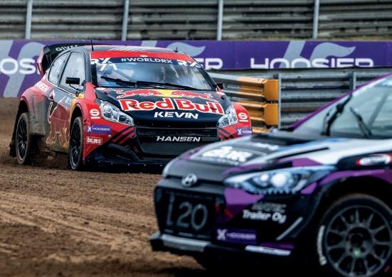
whereby electric and internal combustion engine cars race against each other. Hoosier will remain the official tyre supplier and Volvo Construction Equipment is staying on as the official track builder. Free-to-air coverage will be pursued to get more eyes on rallycross.
‘The championship has huge potential to grow and develop at a global level, and I am confident that this new opportunity for the FIA to operate the championship brings with it a bright future,’ says FIA junior road sport director, Emilia Abel. ‘The FIA will put fans and competitors at the heart of the work that is to come. All of us are looking forward to the 2025 season, and being a part of this new era of rallycross.’
The move has been welcomed by triple teams champion, Hansen Motorsport. An optimistic statement from the Peugeot outfit said the plans promise to ‘ensure the growth of our sport’ at all levels.
The DS Penske Formula E team has expanded its simulation infrastructure with a set of four Theta Seat Sport sim rigs from Ansible Motion. It enables the person in the team’s driver-in-theloop (DiL) simulator, which was installed at Penske Autosport last year, to interact with those using the facility’s four ancillary rigs. The idea is to replicate multi-vehicle racing scenarios away from the racetrack.
Despite being at the cutting edge of vehicle dynamics simulation, a DiL rig has the disadvantage of only running one human-driven car. The Theta Seat Sport it has been paired with is much smaller than the main, 360-degree DiL structure, resembling the type of rig used in esports competitions. AVL Racetech was brought in to establish a smooth connection between the two simulator types.
‘DS Penske’s multi-simulator enables the customer to simulate highly realistic race scenarios, creating a unique testing environment for the development of racecar set-ups and energy management strategies,’ says AVL’s Guillermo Pezzetto. ‘The vehicle dynamics simulation must be capable of realistically modelling the physical effects of running in traffic, which is exactly what our AVL VSM Race software is doing.’
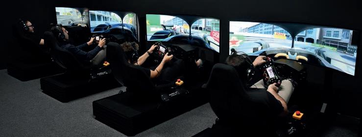
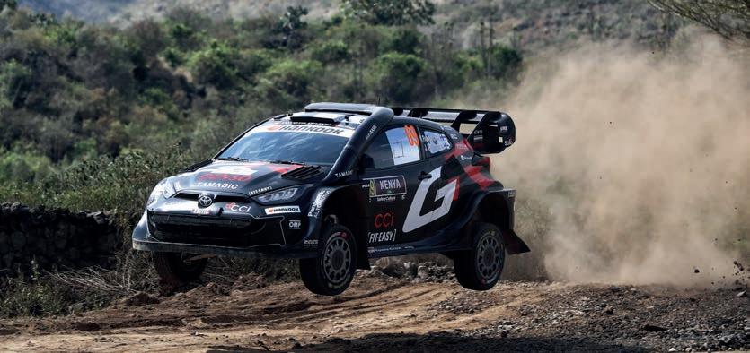
The FIA World Rally Championship has been forced to switch fuel supplier from P1 Performance Fuels to TotalEnergies for the remainder of the 2025 season, starting at the end of April.
According to documents filed in Germany’s company register, P1 entered insolvency in February. This led to it being no longer able to fulfil its commitment to supply the WRC with 100 per cent sustainable fuel.
An insolvency administrator was put in charge of its assets, while the FIA had to find an alternative
supplier quickly and so turned to TotalEnergies, which already provides the FIA World Endurance Championship and FIA European Truck Racing Championship.
The French multinational company will supply sustainable racing fuel to the priority drivers at round four of the WRC season, held in the Canary Islands at the end of April. It will expand distribution to all crews at subsequent rallies.
The FIA also confirmed it will reassess submissions received for the single supply of fuel from 2026-2028.
P1 was also due to make its debut in the DTM this year, but the German GT3 series is switching to UK-based Coryton in advance of its season opener in April. Coryton is set to deliver a sustainable fuel with synthetic components developed in line with the DTM’s specifications. This is to ensure the fuel has similar properties to the P1 fuel, easing the burden on teams.
Coryton is expected to supply the same product to ADAC GT Masters and GT4 Germany, which form part of the DTM event package.
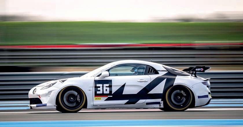
Andretti Global is moving its IndyCar, Indy NXT and Formula E teams to a new Indianapolis headquarters that is set to be operational this summer. The 240,000ft.sq building is a former printing works that will be renovated to include facilities for fabrication and race team operation.
M-Sport will use Liqui Moly lubricants for its British Touring Car Championship engine this year. ‘This partnership supports the hardware development that has taken place over the winter period and helps provide an extremely exciting engine package for the BTCC grid,’ says Liqui Moly TOCA programme manager, Liam Little.
A new, curved windscreen for the H24EVO hydrogen prototype has been developed by Isoclima. The FIA-compliant feature is made of 6mm monolithic polycarbonate and contains hard coating, nonheated and bonded bushings.
The IMSA Sportscar Championship will add a fifth endurance race next year, with Road America staging a six-hour contest on 2 August. Since the 1950s, the Wisconsin venue held a 500-mile race that often ran over four hours, but it was reduced to under three when the current series was launched in 2014.
Aston Martin’s new F1 wind tunnel commenced operations in early March. It forms part of the team’s growing Silverstone campus. The tunnel is supported by a fabrication area for the 60 per cent scale models used in aerodynamic testing.
The Alpine F1 team has become a partner of the STEM On Track programme, a UK-wide initiative that aims to build interest in science, technology and mathematics among school children.
Toyota’s North American arm has introduced a new Camry body for the Trans Am TA2 Series. The kit made its debut in the March round at Road Atlanta, and was developed alongside spec body manufacturer, Five Star Racecar Bodies.
Red Bull is pioneering the use of generative AI to lodge penalty appeals during F1 races. The team’s title sponsor, Oracle, has developed a solution consisting of retrievalaugmented generation (RAG) combined with a large language model (LLM) that will scour past and present regulations to lodge a protest within the 30-minute window after a penalty has been issued. Previously, such appeals were composed by human team members.
Stricter rear wing deflection tests were brought in for the Chinese Grand Prix in March. They built on a clampdown introduced at the F1 seasonopener in Australia to address the so-called ‘mini-DRS’ effect that was observed on the McLaren MCL38 last season. Now, the slot gap cannot vary by more than 0.5mmn (down from 2mm) when a 75kg load is applied. In China, a tolerance of 0.25mm was permitted. Tougher front wing tests are due at round nine in Spain.
The FIA has published a set of technical guidelines for grassroots touring car racing in developing countries. They focus on safety, giving local FIA clubs a blueprint on which to base the rules for their series, while also allowing them to define their own powertrain and vehicle specifications.
Former Jordan F1 team boss, Eddie Jordan, passed away on 20 March aged 76 after a battle with cancer. Jordan’s squad gained fame for its exuberance, and its ability to punch above its weight on track, winning four grands prix and introducing several future star drivers. Its best result was third in the 1999 constructors’ standings. After selling his team to Midland, Jordan went into broadcasting and worked as an advisor, most recently with Adrian Newey.
Racewear company, Walero, has launched its new 2.0 range of temperature-regulating base layers. The products, which contain a material first tested in NASA’s space programme, have been homologated to the latest FIA 8856-2018 and SFI 3.3 competition standards.
Three FIA Formula 2 teams have been fined €10,000 (approx. $10,890) and are set to have their in-season testing time curtailed for drilling holes in their cars’ diffusers to install air pressure sensors. The sanctions against DAMS, Rodin Motorsport and Trident were handed out ahead of the season opener in Melbourne, based on findings made during an earlier test at Barcelona.
According to an FIA stewards’ report, the sensors were installed to measure external airflow, although the investigators could not determine how much data had been collected. F2 regulations prohibit modifying a part to fit a sensor.
The stewards’ report stated: ‘The collection of this data from pressure sensors in the external airflow could be used to correlate with the data from the [spec] chassis manufacturer with the intention to gather more information on the aerodynamic performance of the car in on-track circumstances with different set-ups. Previously, teams have requested such permission from the technical delegate, and it has been denied.’
In separate stewards’ reports, the teams involved admitted modifying the spec diffuser and apologised for doing so and for not seeking permission.
The DAMS representative said that while the team was prepared to collect data from the illegally fitted air pressure sensor, it chose not to use it because enough information had been gathered from the F2 car’s permitted sensors.
In addition to fines, the stewards recommended excluding each team from one day of the next official test in Bahrain and advised the F2 technical delegate to forbid
all teams from running similar sensors during that session. They also imposed 10-place grid drops for each of the six cars involved at the Melbourne round. The threelayered sanction is designed to deter future infractions, address any short-term performance gains and ‘reinstate the fair competition’ between teams in the future.
The stewards continued: ‘This breach has provided the team with data they could use to gain competitive advantage that would endure beyond any single competition… possibly for the entire lifetime of the specific chassis.’
The use of torque sensors in motor racing will continue to expand this year as the devices will be run in the FIA GT World Cup for the first time. The FIA announced that GT3 cars competing in the annual Macau street race will have sensors fitted on their driveshafts to measure power output at the wheels. This will form part of the BoP in a race where manufacturers often provide increased support to their customer teams.
‘As always with competitions relying on Balance of Performance, our goal as the regulator is to ensure a level playing field for all participants,’ says Fabrice Van Ertvelde, FIA technical circuit sport manager. ‘The implementation of torque sensors is a very effective tool to achieve that target, allowing us to realign all the very different cars on parameters such as pure power but also on top speed, which is a
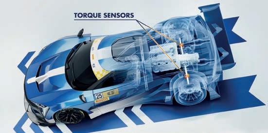
crucial factor on a track such as the Guia Circuit. The manufacturers we are expecting to see in Macau this year are already familiar with this innovation through their experience in the LMGT3 class in the FIA World Endurance Championship, and the decision to go with the torque sensor route is a result of a dialogue we had with them.’
In addition to Macau and the FIA World Endurance Championship, torque sensors were introduced to the IMSA Sportscar Championship’s GTD class for GT3 machinery this year. They have also been used in Formula E, the FIA World RallyRaid Championship and are being considered for the FIA World Rally Championship in 2027.


Editor Andrew Cotton
Email andrew.cotton@chelseamagazines.com
Deputy editor Daniel Lloyd
Email daniel.lloyd@chelseamagazines.com
Sub editor Mike Pye
Art editor Barbara Stanley Technical consultant Peter Wright
Contributors Mike Breslin, Lawrence Butcher, Jamie Klein, Danny Nowlan
Photography James Moy
Acting Director of Commercial Revenue Simon Temlett
Advertising manager Doug Howard
Tel +44 (0) 20 7349 3796; +44 (0) 7743 192 575
Email doug.howard@chelseamagazines.com
Marketing executive Loulou Easton
Email loulou.easton@chelseamagazines.com
Publisher Greg Witham Managing director Marie Davies
Editorial and advertising
Racecar Engineering, Chelsea Magazine Company, 111 Buckingham Palace Road, London, SW1 0DT Tel +44 (0) 20 7349 3700
Subscriptions Tel: +44 (0)1858 438443
Email: racecarengineering@subscription.co.uk
Online: www.subscription.co.uk/chelsea/help
Post: Racecar Engineering, Subscriptions Department, Sovereign Park, Lathkill St, Market Harborough, Leicestershire, United Kingdom, LE16 9EF
Subscription rates UK (12 issues) £84 Europe (12 issues) £100/€120
ROW (12 issues) £120/USD$165 racecar@servicehelpline.co.uk Back Issues
www.chelseamagazines.com/shop
News distribution
Seymour International Ltd,
2 East Poultry Avenue, London EC1A 9PT
Tel +44 (0) 20 7429 4000
Fax +44 (0) 20 7429 4001
Email info@seymour.co.uk
Racecar Engineering (ISSN No: 0961-1096, USPS No: 463) is published monthly by
The Chelsea Magazine Company Limited, and distributed in the USA by Asendia USA, 701 Ashland Ave, Folcroft PA. POSTMASTER: send address changes to Racecar Engineering, 701 Ashland Ave, Folcroft, PA. 19032. Printed by Walstead Roche Ltd Printed in England ISSN No 0961-1096 USPS No 007-969

The Motorsport Industry Association’s Energy Efficient Motorsport (EEMS) conference at the National Motor Museum in Gaydon in March had a little extra bite to it this year. The conference was not necessarily about the direction in which motorsport should be travelling; instead speakers focused on government regulation that does not meet with reality. Their targets, and methods proposed to reach it, are simply not achievable in the real world, while technology already proven in racing, such as low-carbon fuels, or that which is coming, such as hydrogen as a fuel source, are not even being considered.
The message from the conference was that we are resource limited. Government targets in the United Kingdom and Europe ban the sale of new internal combustion engine cars by 2030 and 2035, respectively. The focus is to replace all cars with battery electric vehicles, but there is not enough raw material to meet this demand. There is not enough mining capability to dig the elements out of the ground to build the number of batteries required, and so instead we have to look at how to make the resource we do have go further.
This means producing more batteries, but smaller in size, which points towards hybrid vehicles. Having more cars change to hybrid, either plug in or mild, will have a more positive net effect than a smaller number of fully electric vehicles. Once that becomes an accepted fact, the next stage is to introduce sustainable, low-carbon fuels to replace petrol and / or diesel.
Such fuels are already in use in racing, with the FIA World Endurance Championship, FIA World Rally Championship, IndyCar and many more using their own products. They are not carbon free, nor necessarily perfect, but they are proof the technology exists, and deserves proper investment and development.
There is a strong case for hydrogen too and, as we detail elsewhere in this edition, there is plenty of development going on in that sphere. The work is not only being undertaken by some of the big automobile manufacturers, but also by smaller, more agile companies that are willing, and able, to take risks. Storage remains the big issue here, whether as a gas or liquid, and that takes energy, but there are alternative solutions starting to emerge that deserve to be given due consideration.
Again, the technology is not mature, yet, but it could be with the right backing and investment.
There is some sympathy from the European Union in Brussels, and from countries that have strong motoring industries. They are pushing the zero-emission target, rather than focusing solely on electric. Not only does that mean we can make the available resource go further, but also that there is a long-term future for ICE, which will then encourage investment in low-carbon, or zero-emission solutions. If it is deemed there is no future for ICE, there will be no investment, and, without that, possible realistic solutions cannot be properly funded.
Pascal Vasselon, head of motorsport strategy development at Toyota Gazoo Racing, is leading the company’s research on alternative powertrain solutions. During his presentation at EEMS, he highlighted the fact that more than 75 per cent of cars in Asia are over 15 years old. In the US, the figure is over 40 per cent. Not only do the electric cars to replace them have to be available, they have to be affordable and, more importantly, there needs to be a market for them.
The logical move, then, is to delay, or abandon entirely, the proposed bans on the sale of ICE only cars, and refocus the target onto lower emissions, pushing towards carbon-free mass transport.
The overriding message from the EEMS conference was that it would be better to do something now, rather than push for something in the future that is physically unachievable. Having more cars running with lower emissions now is better for society as a whole than having a few cars with zero emissions in the future.
How does all this link to racing? Very simply, it means the sport either needs to be a hotbed of development, which is expensive, or a disruptive technology source, except the regulations currently don’t allow this. There are still places that do, such as Pikes Peak, which is becoming increasingly attractive for testing new technology, but mainstream racing is still chasing big audience numbers. Formula 1 has new hybrid regulations in place for 2026, while Le Mans will have its hydrogen category in 2029. The reduction in carbon is happening, but it is slow progress and needs to happen quickly.
ANDREW COTTON Editor
Since 1999
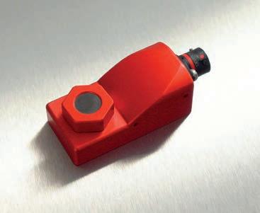

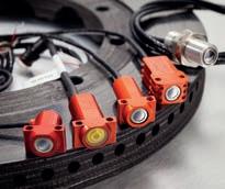


With unique Fade Resistant Technology™, Halo P1 has a far lower and far more stable level of compressibility over a wide temperature range than the competition – giving drivers the confidence that their brake fluid will perform as well on the last lap as the first.