Flexible Rotary Power Transmission Solutions Guide
CATALOG CONTENTS About Elliott Manufacturing A Worldwide Leader 3 Elliott Product Sampling 5 Understanding Flexible Shafts Flexible Shaft Design Solutions 6 Flexible Shaft Components 7 Choosing Your Elliott Flexible Solution Choosing the Right Flexible Shaft 8 Technical Design Considerations 9 Guidelines for Success 12 Flexible Shaft Assemblies .................................. 14 Flexible Shaft Couplings 18 Components 19 Tool Shafts 21 Ordering Standard Flexible Shafts 22 Custom Solutions 23 With thousands upon thousands of unique flexible shaft assemblies in use, Elliott products can be found in an incredibly wide range of applications, literally everywhere. 2


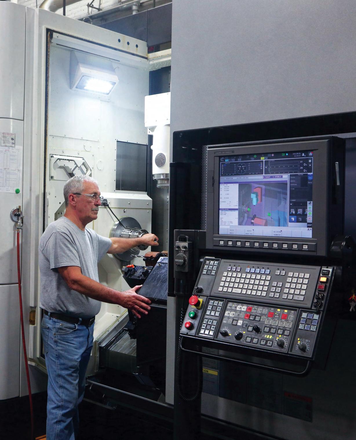
Elliott Manufacturing is a worldwide leader in flexible shaft systems that safely and efficiently transmit rotational power.
Founded in 1932, our product portfolio has evolved to include flexible shaft assemblies, flexible couplings, gearboxes, clutches, push-pull control assemblies, and valve actuation systems.
At Elliott, our consistent and shared focus on product design, quality, safety, innovation, and continuous improvement ensures you and your customers receive the best flexible shaft products available today. Over the years, our engineering expertise, insightful investments in research and development, and ongoing commitment to best-in-class manufacturing have placed us at the forefront of the flexible shaft industry. We’re ISO9001:2015 and AS9100D certified.
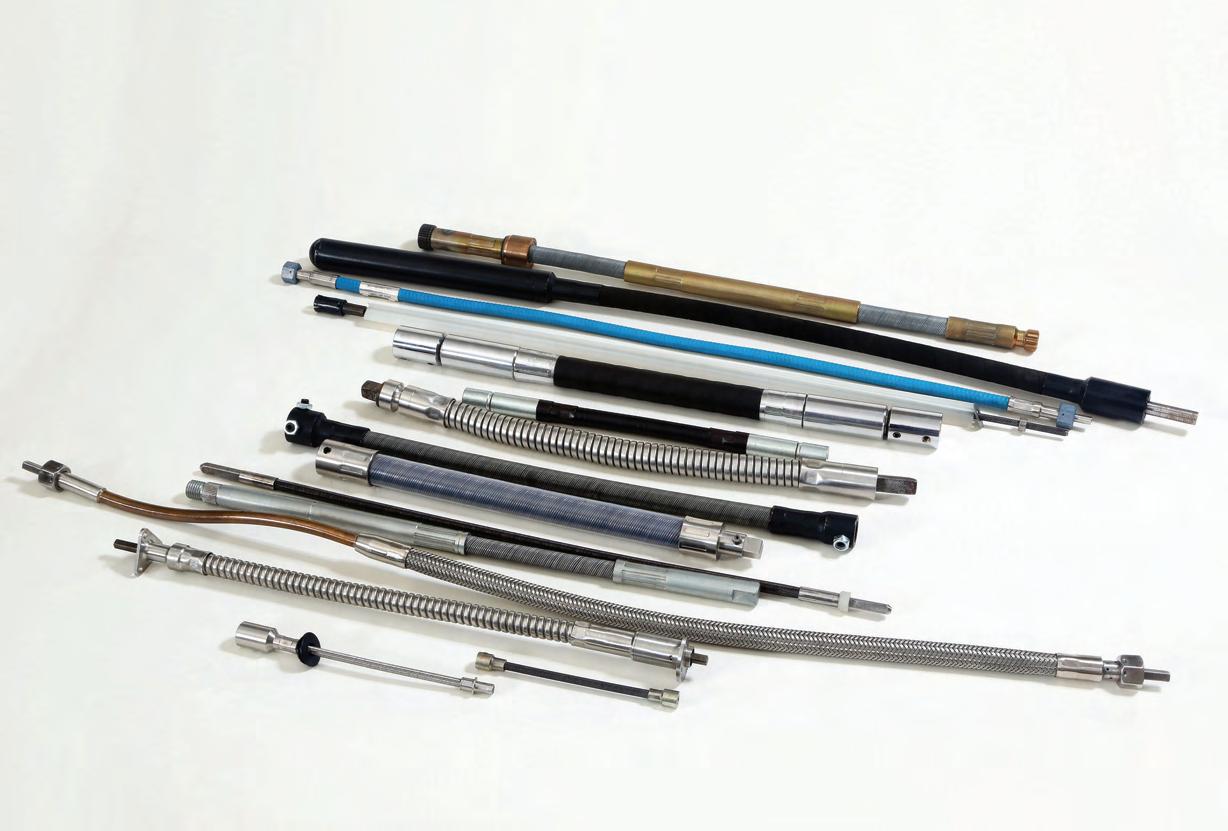
Elliott serves customers around the world, including OEMs, Tier 1 leaders, and a network of aftermarket distributors and agents. Our versatile and innovative transmission technology brings value to challenging and rugged environments in a diverse range of industries, including:
• Aerospace
• Agriculture
• Automotive
• Construction
• Industrial
• Marine
• Medical
• Military
• Outdoor Power Equipment
• Power Generation
• Valve Actuation
• Many Others

3 Need a custom flexible shaft solution? Contact us at +1 607-772-0404 or elliottmfg.com A Worldwide Leader in Flexible Shaft Systems Elliott is the #1 supplier of flex shafts to the global gasoline-powered trimmer market.
know?
Did
you
Elliott flexible shafts efficiently and reliably transmit power to a driven element that must move during operation, even around corners or into machines. With an extensive line of standard products, the design expertise to create custom systems, and a modern in-house machine shop, Elliott is your one-stop source for a complete flexible power solution.
What problem can we solve for you?

Contact Elliott today for a Customer Design Specification Sheet to start defining your application!
See page 13 for details.
4
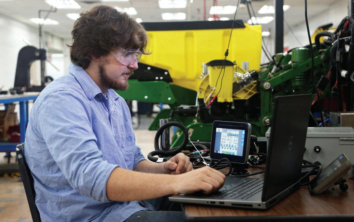
FLEXIBLE SHAFT DRIVE SYSTEMS FOR AGRICULTURE
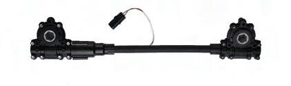
Elliott offers flexible shaft drive systems, gearboxes, and clutches for seeders that bring enhanced row control performance to most planters on the market today — providing a mechanical advantage without the need for additional power sources. Since first introduced in 2003, we’ve built more than two million of these smart solutions to help farmers improve productivity and save time and money:
• Row Control and Row Control+
• Surface Drive

• GroundControl
• FlexSeeder
FLEXIBLE SHAFT AND PUSH/PULL ACTUATION SYSTEMS FOR AEROSPACE
Leading Tier 1 OEMs rely on Elliott shafts for thrust reverser actuation, flap and slat actuation, seat adjustment, and passenger door drives. Our engineers have designed flexible shaft systems for advanced applications on private and commercial planes, military planes, helicopters, tanks, and ground support systems. Extreme environment uses include missile shroud deployment, engine extension and gimbal control, and synchronization.

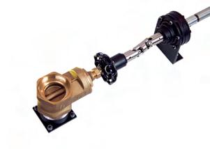
REMOTE VALVE CONTROL SYSTEMS FOR INDUSTRIAL, MARINE, AND POWER GEN
Elliott provides the most versatile, reliable, and proven remote mechanical valve actuation available today. Our flexible shaft solutions for remote valve control systems offer safe valve actuation in some of the world’s most difficult and dangerous locations. Elliott branded systems include:
• Safe Operator Remote Valve Control – A smart alternative to chain wheel valve operators that adds security and reliability in industrial plants
• Uniflex-Stowe Remote Valve Control – Precision-engineered system for critical environments such as naval and nuclear applications
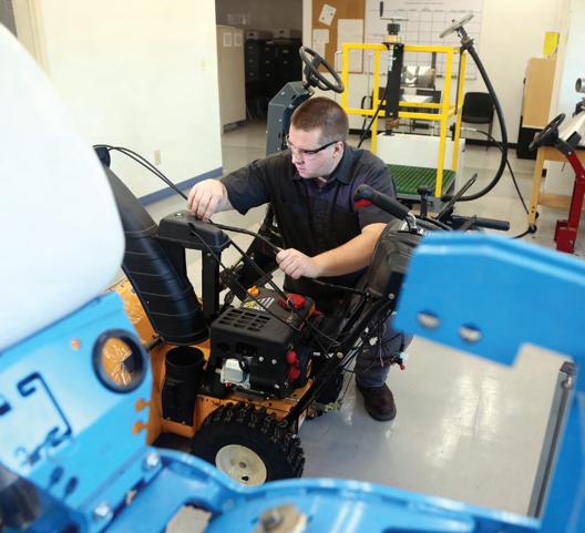
FLEXIBLE SHAFT PRODUCTS FOR OUTDOOR POWER EQUIPMENT
Elliott is the #1 global supplier to the gasolinepowered weed trimmer market. Our shafts also help to remotely position starters and provide flexible steering shafts in UTVs and direct snow discharge chutes on snow throwers.
Did you know?
FLEXIBLE SHAFT PRODUCTS FOR CONSTRUCTION
Elliott’s dependable and durable flexible shafts are used in a range of construction tools, such as concrete vibrators, power screeds and trowels, drywall sanders, and duct cleaners.
Elliott has push/pull cable assemblies for all markets. What problem can we solve for you?
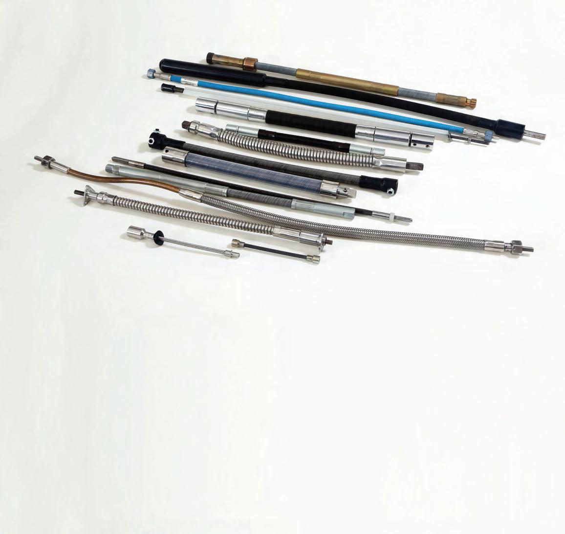
5 elliottmfg.com Elliott Product Sampling in Key Markets
Flexible Shaft Design Solutions
Elliott flexible shafts can solve your power transmission problems...fast.
They are ideally suited for transmitting power over, under, around, and even through obstacles that would hinder other systems. They can overcome problems of misalignment, and absorb and isolate vibration, significantly simplifying your transmission application.
Our flexible shafts can easily withstand the shock of sudden load changes due to starting and stopping. They will transmit power to a driven element that must move during operation, around corners, or into machines — all while allowing for a high degree of freedom in mounting drive units such as electric motors.
Solve complex drive problems easily with an Elliott flexible shaft. Reduce your design time,and lower your assembly and maintenance costs safely without the use of exposed universal joints, gears, pulleys, or couplings. Consider Elliot flexible shafting early in your design process to take full advantage of our ability to solve demanding drive problems efficiently, economically, and with the flexibility you need.
COMMON POWER DRIVE PROBLEMS. SMART FLEX SHAFT SOLUTIONS
OBSTACLES
DIRECTION CHANGES
VIBRATION ISOLATION
DIFFICULT POSITIONS
MOVING POSITIONS
PARALLEL OFFSET
LIMITED ACCESS
Elliott flexible shafts are the simple answer to all typical power transmission challenges...and so much more.
6
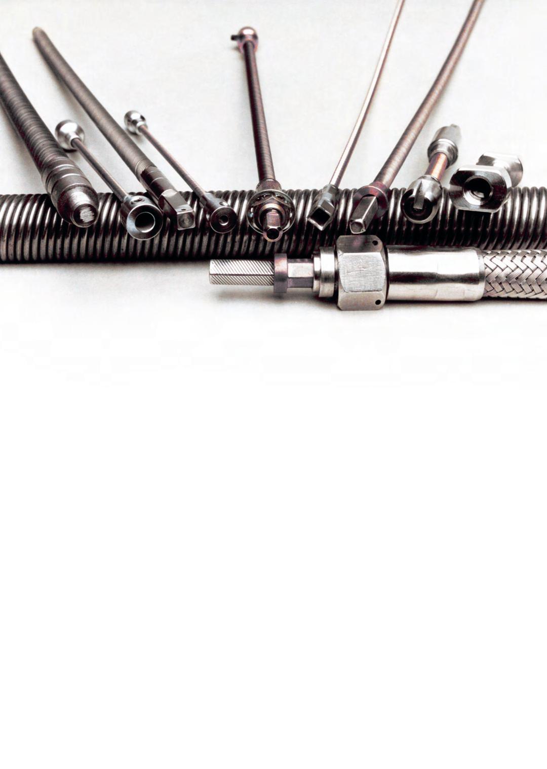
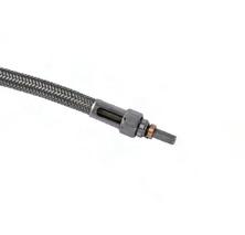
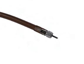
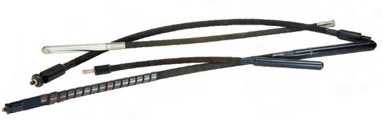
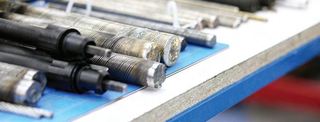
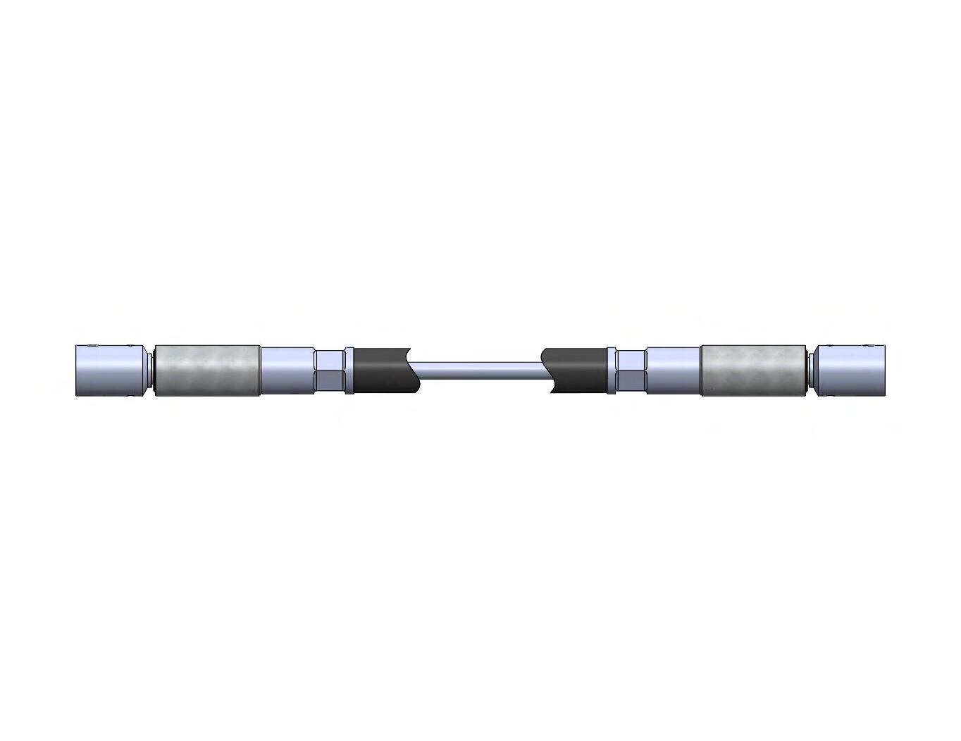
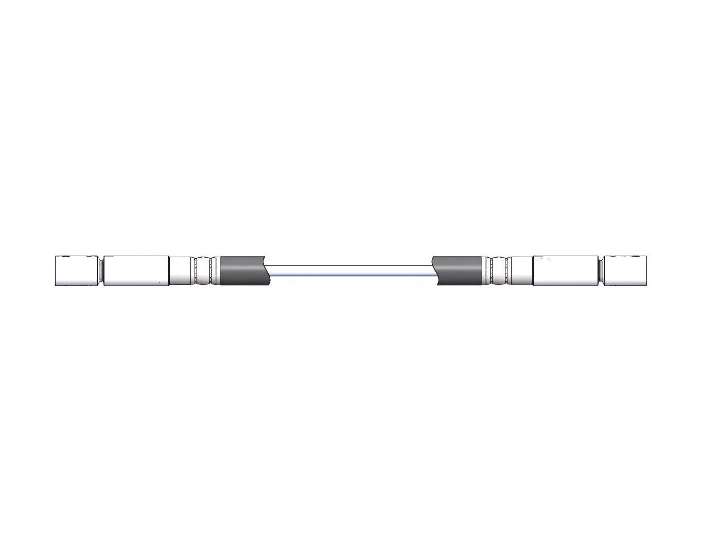
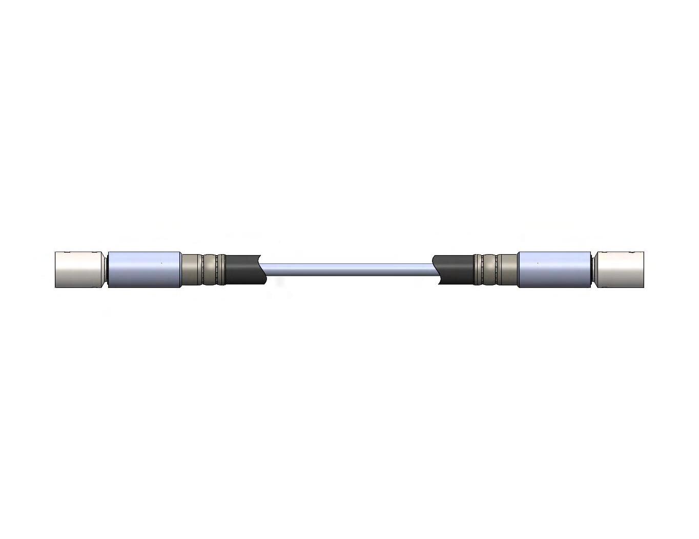
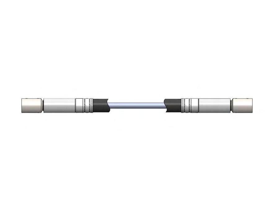
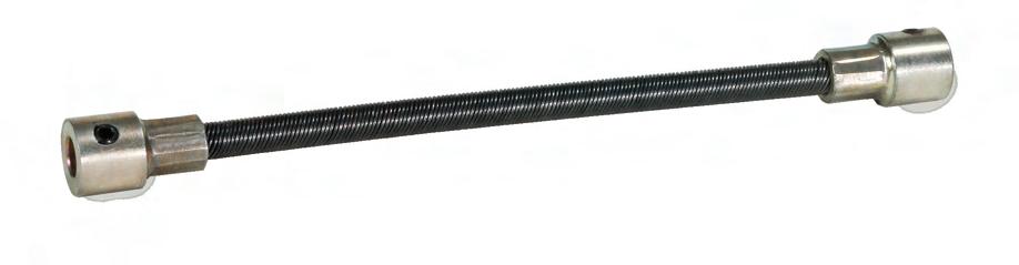
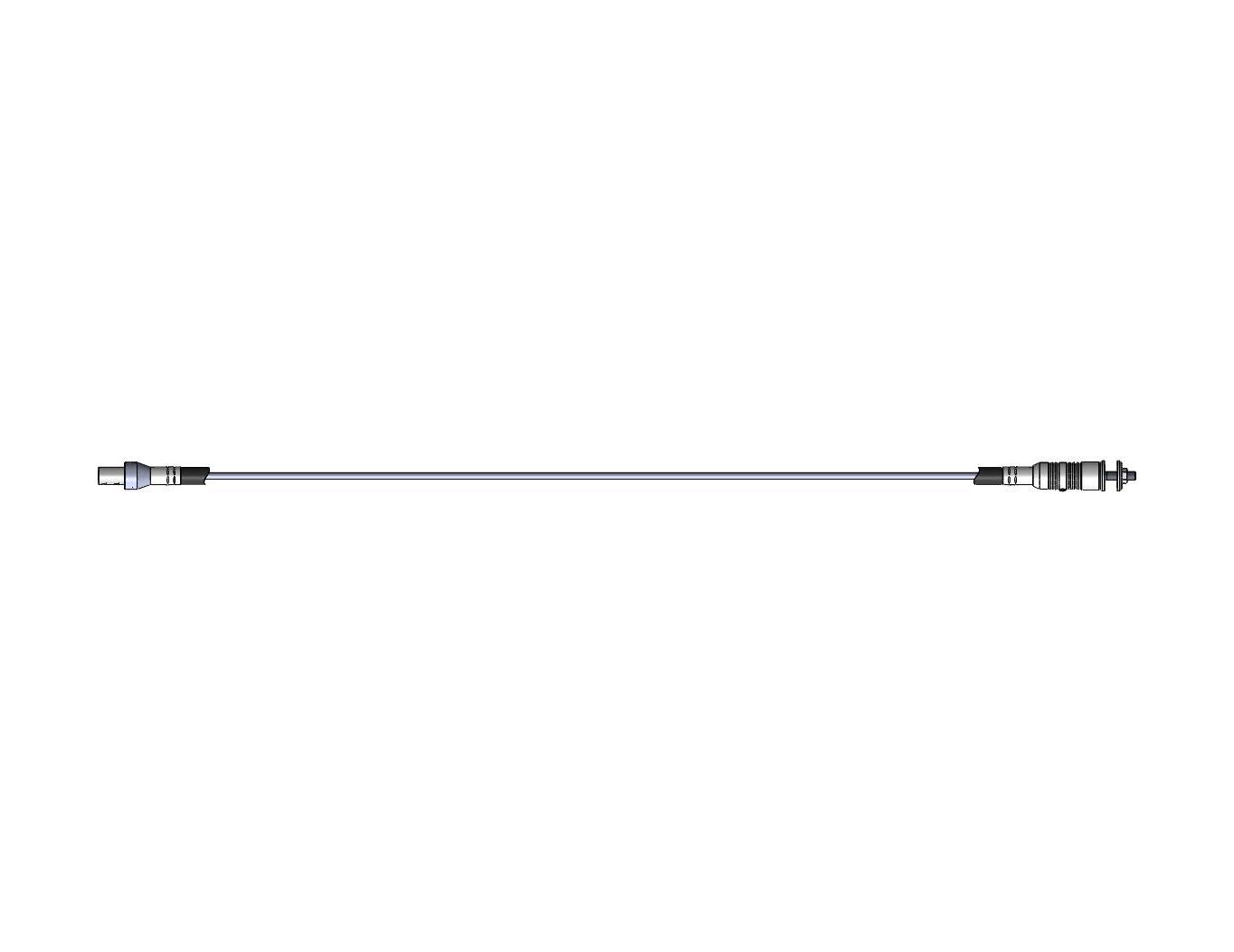
Elliott flexible shaft components are precision engineered and meticulously crafted for a lifetime of efficient and worry-free service.
Core Fitting Motor Connection
CORE: Core size is determined by the load and rpms transmitted through the shaft. Elliott cores are wound with multiple layers of wire and are available in a variety of materials, constructions, and sizes.
• Core sizes range from 0.125” to 1.625”
• Support up to 10HP and 0-50,000 rpms
Ferrule

COUPLINGS: These female sockets are located at the end of the flex shaft assembly and engage the mating components within your equipment.
• Range from 0.125” to 0.500” core diameter
• Plain bored fittings provide easy attachment with set screws
• Custom-designed couplings are available to fit existing equipment or to provide ideal connection solutions
FITTINGS: Fittings are machined or formed components that attach to the ends of the core to connect driving and driven elements.
• An infinite number of designs are possible to best mate with your power source
• Whenever possible, choose the simplest drive, — a male square formed on the end of the core
Liner Core
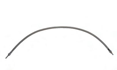
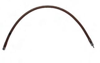
CASING: The casing, or flexible conduit, protects and supports the core during operation and prevents helixing under load. Elliott offers a range of casing designs to enhance performance and prolong life in varying environmental conditions. Our casings are engineered to exhibit a minimum amount of stretch and twist, and to provide a uniform bearing surface for the core
• Choose from materials that withstand dust, oil, moisture, abrasion, and temperature extremes
• Casings have a steel or polymer liner, steel and/or cloth reinforcing braids, and an elastomer cover
FERRULES: These are the terminals attached to the end of the casing. They support uniform bending and prevent casing rotation. A wide variety of designs are available to best meet your application.
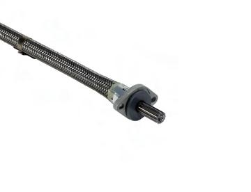
MOTOR CONNECTION: Elliott flexible shafts rely on a range of diverse end connections. They can be as simple as a single fitting or can contain multiple parts to form the most efficient motor connection. Along with connecting the flexible shaft to a power source, end connections also offer added support for the casing.
MATERIALS AND FINISHES: All Elliott machined parts, fittings, ferrules, and motor connections are made from quality, cold-finished steel. Standard finishes are black oxide or zinc plate. Custom materials and finishes are available.
7 elliottmfg.com
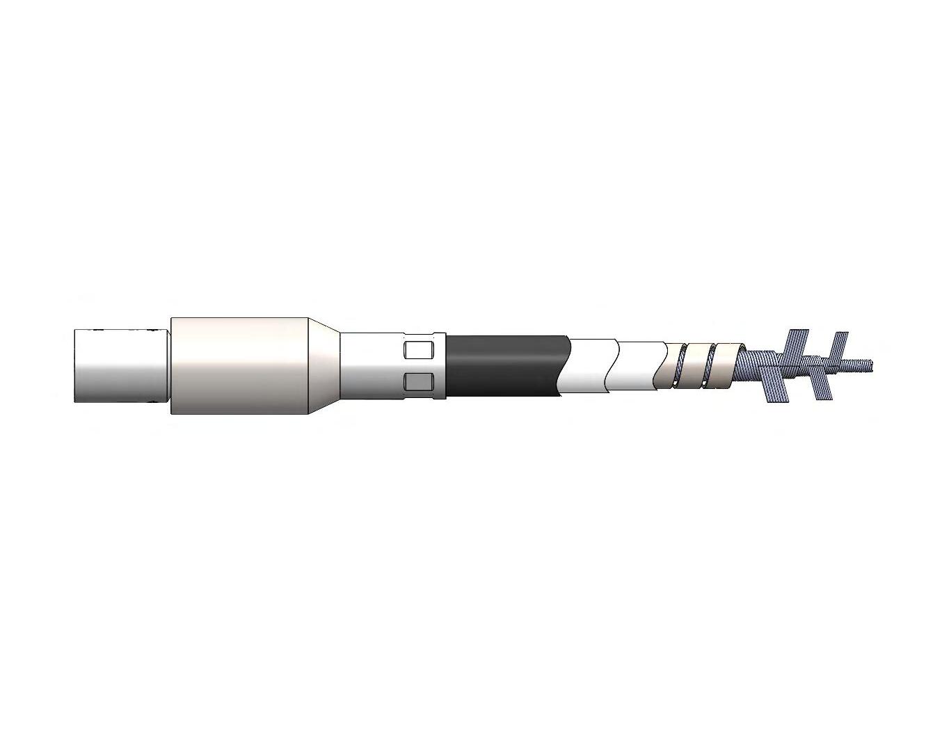
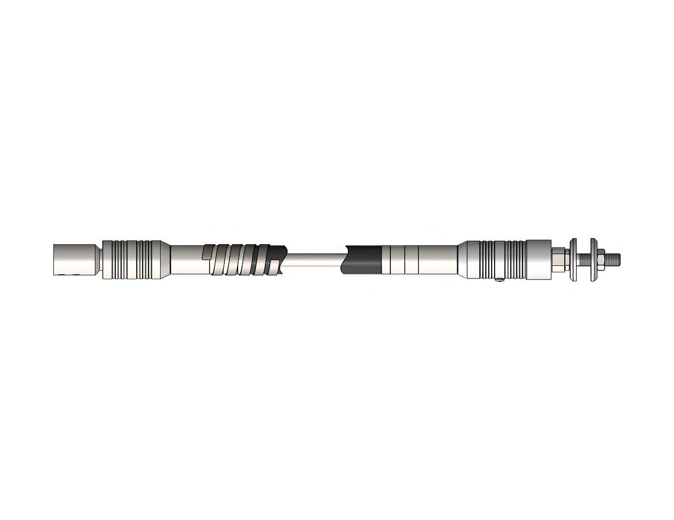
Flexible Shaft Components
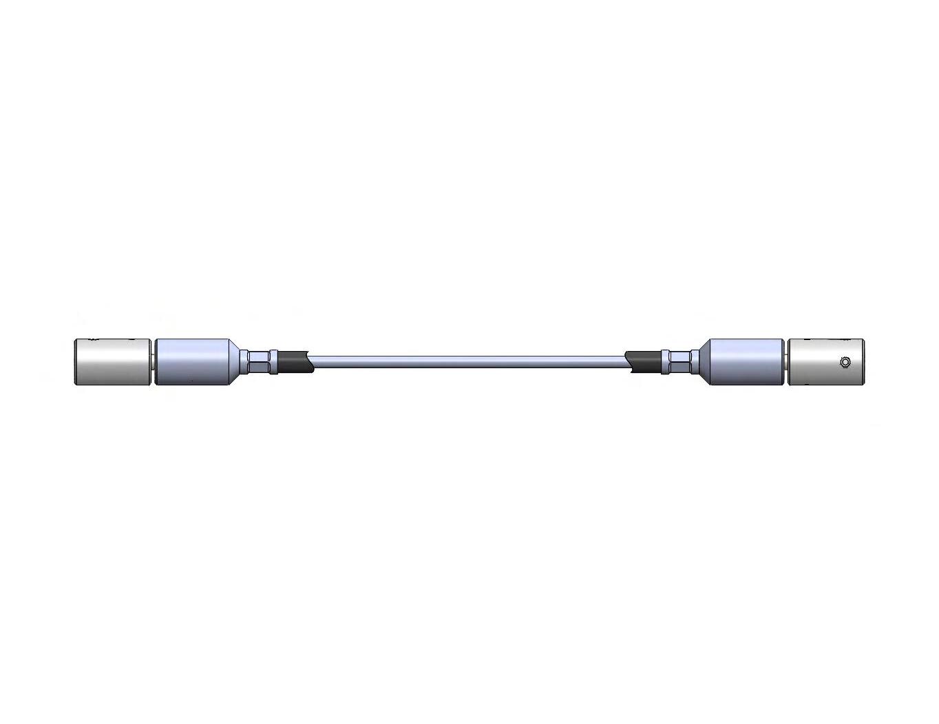
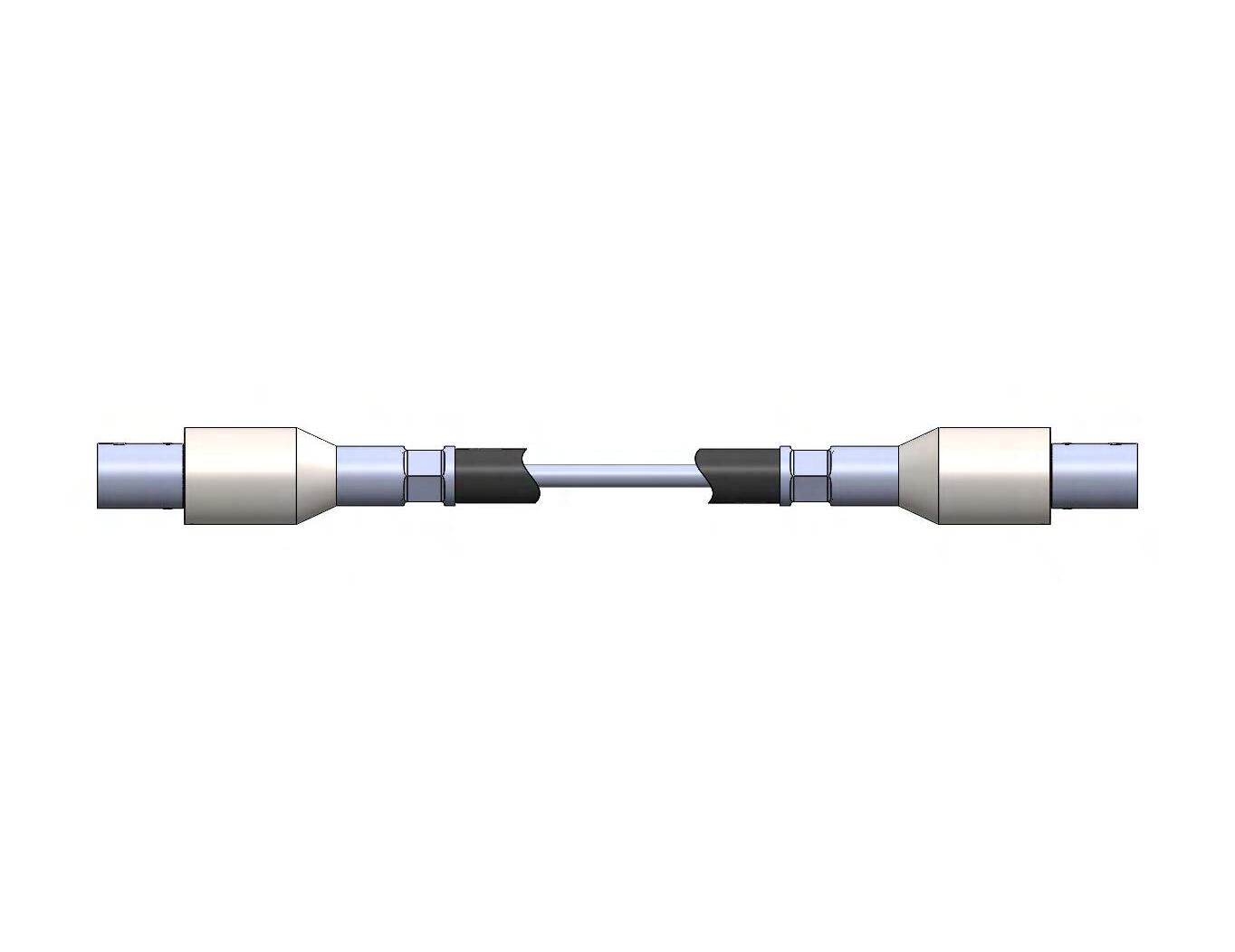
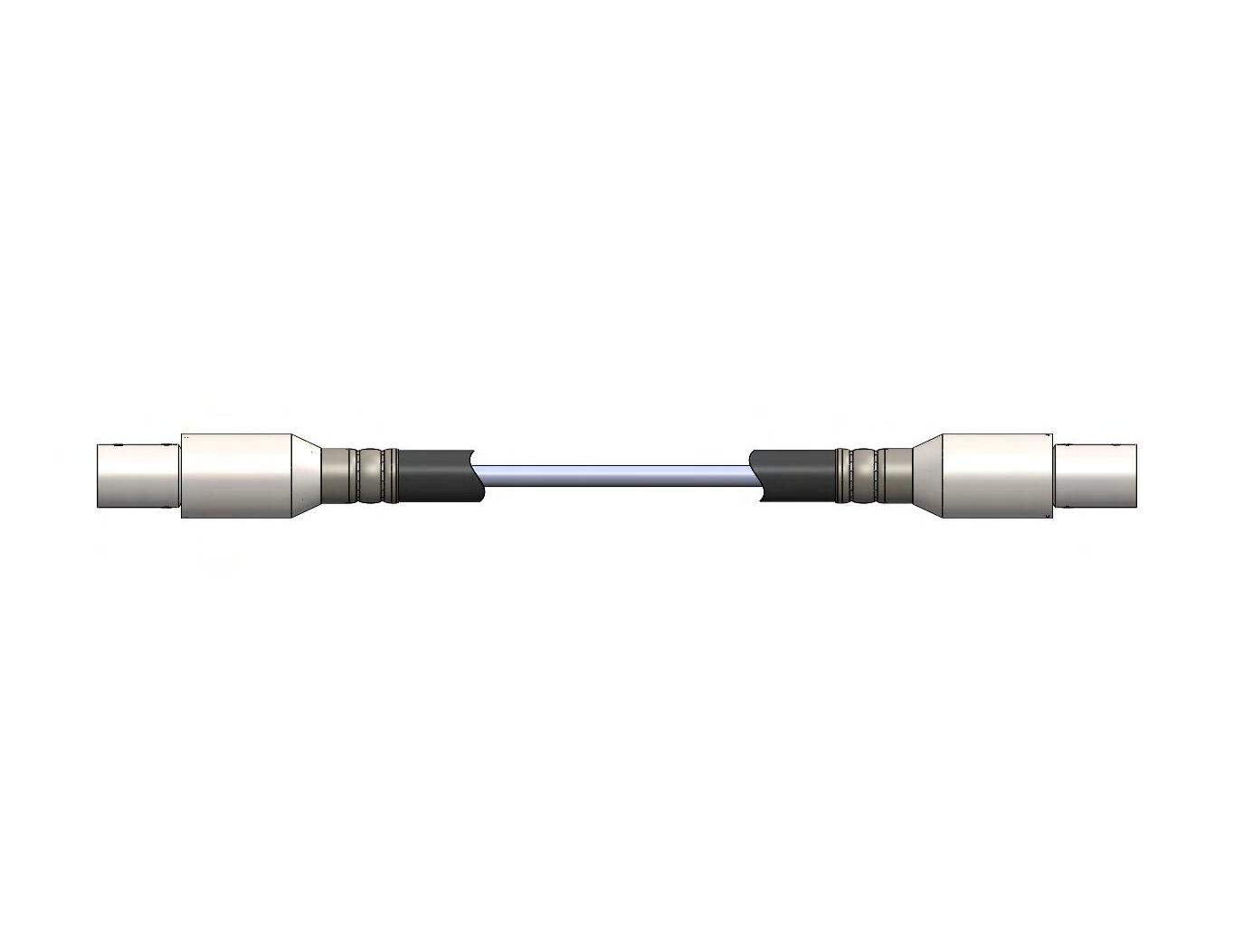
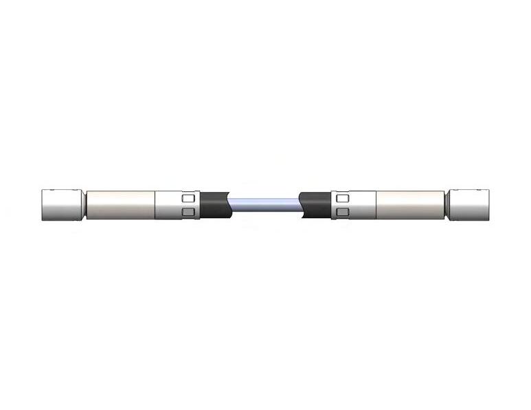
A RELEASED FOR PRODUCTION; EWR XXXXX 2 2 3 3 4 4 5 6 5 6 SCALE: 2:3 APVD KCP 07/19 CHKD KCP 07/19 FINISH: DRWN 07/16/19 JSM ~~ ~~ .625 FLEXIBLE SHAFT ASSEMBLY ~~ ±1° ±.015 ±.003 ±.01 LTR REVISION B SIZE TITLE 72166 ID CODE CAGE NO. DATE MATL: UNS NO. REMOVE ALL BURRS & SHARP EDGES. TOLERANCES (EXCEPT AS NOTED) TWO PLACE DECIMALS SURFACE ROUGHNESS THREE PLACE DECIMALS FRACTIONS 63 ANGLES ALL DIMENSIONS ARE IN INCHES UNLESS OTHERWISE NOTED. 409 P.O. BOX 773 BINGHAMTON, NY 13902 DRAWING PREPARED IAW ASME Y14.5M-1994
Coupling Bearing Housing Casing Braid Wire
Choosing the Right Flexible Shaft
STANDARD SHAFTS
Elliott offers a comprehensive line of standard flexible shaft assemblies that may be the simple solution you need. Our standard shafts can be delivered quickly, typically at the most affordable cost and offering the easiest replacement. Always consider a standard shaft first, as it can save you both time and money.
STANDARD SHAFT ASSEMBLY OPTIONS
Choose from three categories of standard Elliott flexible shaft assemblies:
• Ball bearing units for high-speed applications
• Plain bearing units for low and moderate-speed needs
• Flexible couplings with and without casing for more demanding requirements
All of our standard flexible shaft assemblies are available with core for power drive or remote-control service.
Did you know?
STANDARD BALL AND PLAIN BEARING UNITS
Elliott standard ball and plain bearing flexible shaft units are available in a range of sizes, from 3/16” to 1-1/4” core diameters. Each comes with bored couplings and set screws for fast and easy installation to the shank of a drive and driven spindle. All units are fully enclosed with an elastomer covered casing and lubricated during assembly. See pages 9-12 for the load capacity of power drive and remote control shafts. Outline dimensions of all units are detailed beginning on pages 14-17.
FLEXIBLE COUPLINGS
Standard Elliott flexible couplings are offered in sizes from 1/8” to 1/2” in core diameter with and without casing. All Elliott flexible couplings arrive with plain bored fittings for easy attachment with set screws. If your application requires a longer flexible coupling, over 12”, add a casing for extra support and increased capacity. Learn more on page 18, including torque capacity and outline dimensions.
For unique applications, stringent requirements, or high volume quantities, Elliott engineers are always available to design a custom flexible shaft solution to meet your exact needs.
8
TYPES OF CORE
Elliott manufactures flexible shafts with cores of varying materials, construction, and technique to provide a range of high quality options. Power Drive and Remote Control are the two basic core types.
1. Power Drive cores transmit rotary motion continuously in one direction. They are made of high carbon flexible shaft wire and wound on leading-edge automatic winding machines. Stress relief is precisely controlled to provide optimum flexibility and smoothness.
2. Remote Control (bi-directional) cores transmit rotary motion in both directions at slow speeds (<100 rpms) or high-speed, intermittent applications. They also exhibit a minimal amount of angular deflection (wind up) in both directions of operation. Remote control cores use a greater number of wires and layers, all precisely calculated for nearly identical properties of deflection and strength in both operational directions.
WHAT TO KNOW
To choose the proper diameter core size for your application, you must know the power to be transmitted — either hp or torque and rpm — along with your radius of operation. To reduce the torque load on the core, transmit power at the highest possible RPM. You may be able to use a smaller diameter shaft if you gear the core to run at a higher rpm, which can lower the applied torque below the maximum dynamic torque capacity. This applies if you are limited by the dynamic torque capacity in choosing your core.
DIRECTION OF ROTATION
You must also consider the direction of rotation, especially in a power drive core. If operated in the wrong direction, it will transmit as much as 30% less power. Standard
Technical Design Considerations
Use the instructions here and the tables on pages 10 and 11 to identify the proper core for your application.
power drive cores are offered in both directions of wind; right hand for clockwise operation and left hand for counter-clockwise operation. Standard remote control (bi-directional) cores are offered in right hand wind for both directions of operation. Observe your direction of operation from behind the driving end to determine what type of wind you need.
This is an example of clockwise operation, which requires a right hand core.
OPERATING RADIUS
When choosing a flexible shaft, do not exceed the minimum radius of operation, or the smallest radius in which a core can be operated. Use your actual radius of bend to select the core size.
TORSIONAL DEFLECTION
Torsional deflection, or the angular wind up of a core, is a factor when the angular orientation between input and output is required within specific limits. Review this information carefully as it may dictate the diameter core needed for your application.
SPECIAL CONSIDERATIONS
Temperature, magnetic fields, or corrosives may be other considerations. Using special materials can solve any of these challenges. Talk to an Elliott representative for recommendations on your particular application.
elliottmfg.com
9
Technical Design Considerations for Power Drive
FOR POWER DRIVE
To choose the right diameter Elliott core for power drive flexible shaft applications (over 100 rpm), you must know:
1. Hp and torque to be transmitted by core
2. Rpm
3. Minimum radius of bend
4. Maximum torque (starting or stopping)
5. Direction of rotation
In the table below, locate the hp value of your application in the proper column under “Radius of Operation.” Compare your actual torque to the maximum dynamic
torque capacity taking care not to exceed it. If you do exceed the maximum dynamic torque capacity, continue down the column of Radius of Operation until you reach a value large enough for your application.
If your hp is too large, verify if your actual torque requirements are within the range of flexible shafting. Use the following formulas to calculate your power requirements.
torque = hp x 63,000 hp = torque x rpm rpm 63,000
H.P. RATING-MAXIMUM DYNAMIC TORQUE (LB-IN) AT GIVEN RADIUS (H.P. Values in shaded area)
RADIUS OF OPERATION (INCHES)
Notes:
A. Each core can transmit hp up to its maximum rpm, as long as the maximum dynamic torque capacity is not exceeded (for higher rpms contact Elliott.)
B. Each core will either break or helix under this load. For short-term overloads (shock loads), do not exceed 50% of this value.
C. Direction of operation is always determined by observing from behind the driving end. Add a (-1) to this part number for clockwise operation and a (-2) for counter-clockwise operation.
10
Nominal Dia Actual Dia Part No (Note C) Wt/100 Ft (lbs) Max. Static Torque Capacity (LB-In) (Note B) Max. Continuous RPM Min Radius of Operation (Inches)
CORE DATA
3 4 6 8 10 12 15 20 25 50 1/8” 5/32” 3/16” 1/4” 1/4” 5/16” 3/8” 7/16” 1/2” 5/8” 11/16” 3/4” 1” 1-1/4” 3.3 4.5 6.8 12.5 12.4 19.2 28.2 38.5 49.6 77.6 91.2 112.7 200 310 12 24 48 96 88 190 250 380 500 700 860 980 1300 1900 20,000 20,000 15,000 15,000 20,000 10,000 10,000 6000 6000 4000 3750 3000 2500 2500 3 4 4 5 5 6 6 6 6 8 10 15 20 20 .04 .5 .18 2.5 .44 7.0 .66 12.0 .87 24.0 .80 22.0 1.10 40.0 1.70 75.0 2.10 90.1 2.60 150.0 3.60 235.0 3.90 260.0 4.80 350.0 7.00 7200 10.0 1200.0 .17 2.3 .40 6.5 .60 9.5 .80 22.0 .75 20.0 1.05 35.0 1.60 70.0 2.00 85.0 2.30 130.0 3.30 205.0 3.60 232.0 4.00 220.0 5.00 5000 9.00 7000 .16 2.1 .38 6.2 .57 9.0 .75 20.0 .70 18.0 1.00 32.0 1.50 65.0 1.80 80.0 2.10 110.0 3.10 190.0 3.40 215.0 3.40 200.0 4.40 380.0 6.00 420.0 .16 2.0 .37 6.0 .53 8.5 .70 18.0 .66 17.0 .91 30.0 1.40 55.0 1.60 75.0 1.80 95.0 2.80 180.0 3.00 198.0 3.00 180.0 .15 1.9 .34 5.8 .49 8.0 .65 16.0 .62 16.0 .82 26.0 1.20 60.0 1.40 65.0 1.50 88.0 2.40 158.00 2.60 172.0 .15 1.9 .32 5.5 .46 7.5 .60 15.0 .58 15.5 ,74 24.0 1.10 48.0 1.20 60.0 1.30 74.0 2.00 132.0 2.20 150.0 .14 1.8 .28 5.0 .40 7.0 .50 14.0 .52 15.0 .62 20.0 .88 42.0 1.00 50.0 1.10 60.0 1.40 100.0 .12 1.6 .24 3.5 .34 5.5 .44 12.0 .46 13.0 .51 18.0 .62 30.0 .74 40.0 .80 50.0 .08 1.0 .10 1.5 .19 4.0 .125 .130 .145 .150 .181 .185 .241 .245 .248 .252 .309 .312 .370 .374 .437 .441 .500 .496 .621 .626 .677 .681 .740 .747 .990 .997 1.240 1.247 10170 10168 10630 8145 8552 9723 8149 8134 8585 8586 9263 8587 8588 8559
Technical Design Considerations for Remote Control
FOR REMOTE CONTROL
To choose the right diameter Elliott core for remote control or bi-directional flexible shaft applications, you must know:
1. Torque to be transmitted by core
2. Minimum radius of bend
3. Rpm of operation (if applicable)
4. Maximum allowable torsional deflection (if applicable)
In the table below, locate a torque figure applicable to your application in the proper column under “Radius of Operation.” Read across for the properties of that particular core. If the deflection listed is unacceptable, move to the next largest size.
Special consideration must be given when using bidirectional cores for power drive applications, both continuous and intermittent. For continuous power drive applications, reduce torque values listed by 70%. On intermittent power drive installations, core can be operated for a short period of time limited by heat built up.
Notes:
A. Each core can transmit this torque in both directions of operation for remote control applications (less than 100 rpms) and intermittent power drive applications (no longer than it takes to raise core temp 70° above ambient with rest duration allowing for core to cool within 30° of ambient). For continuous power drive applications in both directions, use only 30% of these torques.
B. Each core will either break or helix under this load. For short term overloads, do not exceed 75% of this value.
C. Standard remote control cores are wound in the right-hand direction. Add a (-1) to part number for right hand or (-2) for left hand.
11 elliottmfg.com
Nominal Dia. Actual Dia. Part No. (Note C) Wt./100 Ft. (lbs) Max. Torque Capacity (Lb.-In.)(Note B) Max. RPM Intermittent Operation TORQUE RATING (LB.-IN.) FOR BOTH DIRECTIONS OF OPERATION AT GIVEN RADIUS (NOTE A) RADIUS OF OPERATION 3 4 6 8 10 12 15 20 25 50 1/8” 5/32” 3/16” 1/4” 5/16” 3/8” 1/2” 5/8” 3/4” 1” 1 1/4” 1.300” 1 5/8” 3.4 4.8 6.9 12.8 19.7 28.8 54 75 113 200 310 340 600 10 20 45 95 150 220 340 550 670 1300 1900 1920 3000 30,000 20,000 20,000 20,000 20,000 20,000 10,000 7,000 5,000 5,000 2,500 2,500 1,750 1 LB-IN 1 LB-IN 1 LB-IN 5 LB-IN 10 LB-IN 10 LB-IN 100 LB-IN 100 LB-IN 100 LB-IN 960 LB-IN 1900 LB-IN 1920 LB-IN 3000 LB-IN 3.0 6.0 7.5 12.0 26.0 55.0 110.0 140.0 280.0 400 500.0 975.0 1500 1600 2700 7.5 12.0 26.0 55.0 110.0 140.0 280.0 380 500.0 950.0 1200 1300 2500 7.5 12.0 26.0 55.0 110.0 140.0 280.0 370 480.0 920.0 1000 1100 7.5 12.0 26.0 55.0 110.0 140.0 260.0 330 440.0 7.5 11.0 24.0 48.0 96.0 132.0 240.0 300 7.0 10.0 22.0 44.0 88.0 124.0 220.0 275 6.5 9.0 18.0 36.0 72.0 116.0 200.0 5.5 8.0 16.0 32.0 64.0 102.0 3.6 7.0 14.0 28.0 56.0 .124 .128 .145 .150 .181 .185 .245 .249 .307 .311 .374 .378 .496 .499 .614 .618 .740 .747 .990 .997 1.240 1.247 1.292 1.299 1.618 1.611 10171 10169 8144 8146 8148 8150 8296 8172 8587 8588 8559 8660 8663 14° 7° 3.5° 5° 6° 3.5° 10° 2.5° 1.5° 7° 5° 5° 4° 17° 9° 4° 6° 7.5° 5° 13° 3.5° 1.6° 7° 5° 5° 4° Max. Torsional Deflection at Given Torque in Degrees Per Foot Deflection°/Ft. Wind Unwind Torque CORE DATA
Guidelines for Success
You expect consistent, reliable performance from your flexible shaft. These basic guidelines will help you choose the best results.
RADIUS CALCULATION
When designing a flexible shaft application, radius of operation is key. Maintain as large a radius as possible and avoid sharp bends or kinks. Use the diagram and formulas below to calculate radius of operation and shaft length in parallel offset applications.
DETERMINE CORE WIND
Using a sample of the core, observe the lay of the wires to easily determine the direction of wind.
Left Hand Core (counter-clockwise rotation)
Right Hand Core (clockwise rotation)
QUICK TIPS FOR SUCCESS
Do...
• Use hp and torque to determine power requirements and find the proper diameter core for the application.
• Use the highest possible rpm to transmit power and lower the torque load on the shaft.
• Operate the shaft in the largest possible radius, avoiding sharp bends or kinks.
• Install the shaft properly making sure the casing is straight for several inches beyond the ferrule, clamping it into position whenever possible, and avoiding excessive lengths (over 10 ft.)
Don’t...
• Bend a core into a radius smaller than recommended, even during shipment.
• Overlook the direction of rotation in choosing a core.
• Use the flexible shaft to support anything at all. It was not designed to be a handhold, foot rest, or other support.
• Ignore routine maintenance as described.
Hold the core vertically and observe the wires. If they slant down to the right, you have a right-hand core. If they slant down to the left, you have a left-hand core. Use this terminology to describe your flexible shaft requirements to avoid confusion.
CARE AND MAINTENANCE
Flexible shafts require a minimum of maintenance. After every 200 hours of use, the core should be relubricated as the screw action of the winding process shifts the lubricant to one end of the casing.
Remove the core from the casing and clean in a solvent. Remove all excess solvent and re-lubricate with a quality petroleum-based grease with a temperature range of -40° to +250° F. Never pack the casing with grease as it will increase torque load on the core.
12
Z Y R X R = APPROXIMATE x2 + y2 4y Z = 2 APPROXIMATE x 2 + 4 y 2 2 3 2 ( ) ( )
Did you know?
Elliott developed industry-specific “Customer Design Specification Sheets” for applications in the aerospace, agriculture, industrial/general purpose, medical, steering, and valve actuation markets. These sheets detail all of the important design questions on hp, torque, rpm, bend radius, coupling size, and more on one convenient form. Once completed, our application engineers can quickly respond to you with product recommendations. Request yours today.
13 Need a custom flexible shaft solution? Contact us at +1 607-772-0404 or elliottmfg.com

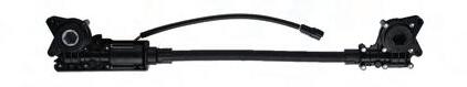
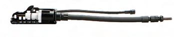
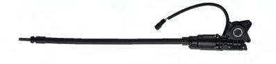
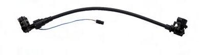
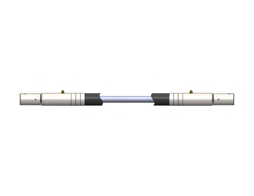
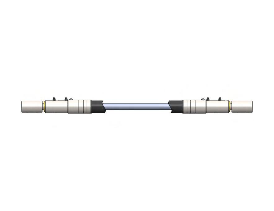
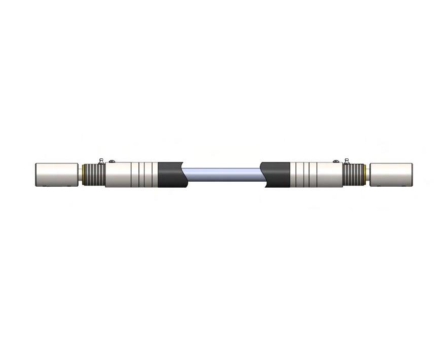
14 JSM KCP 05/19 D 1 DATE APVD BY .188 FLEXIBLE SHAFT ASSEMBLY 7614 REV DWG NO. (BALL BEARING UNIT) KCP 05/19 B C D 1 2 3 4 Model Name:S12653_B-401 5 6 D DATE APVD .250 FLEXIBLE SHAFT ASSEMBLY S12653 M REV SH 1 OF 1 Elliott Flexible Shaft Assemblies - Ball Bearing Units .312* .375* .500* .625* .88 1.50 5.38* 1.12 1.50 .97 .91* .375* CORE (*Nominal-Reference) H ECN XXXX; SEE ECN SH FOR CHANGES; EWR 7628 JSM KCP 05/19 A B B C C D 1 2 3 4 Model Name:S12793_B-404 5 6 D APVD KCP 05/19 CHKD KCP 05/19 DRWN 05/19 JSM DATE APVD BY .375 FLEXIBLE SHAFT ASSEMBLY ±.015 ±.003 ±.01 LTR REVISION REV SIZE TITLE DWG NO. ID CODE CAGE NO. DATE MATL: UNS NO. REMOVE ALL BURRS & SHARP EDGES. TOLERANCES (EXCEPT AS NOTED) TWO PLACE DECIMALS SURFACE ROUGHNESS THREE PLACE DECIMALS FRACTIONS 63 ALL DIMENSIONS ARE IN INCHES UNLESS OTHERWISE NOTED. P.O. BOX 773 BINGHAMTON, NY 13902 DRAWING PREPARED IAW ASME Y14.5M-1994 SH 1 OF 1 Recommended: Speed 6000 rpm Min Lgth. 9 in. Max Lgth. 15 ft. Min Bend Rad. 4 in. Ref P/N 7614 Recommended: Speed 6000 rpm Min Lgth. 13-1/2 in. Max Lgth. 15 ft. Min Bend Rad. 8 in. Ref P/N S12793 Recommended: Speed 6000 rpm Min Lgth. 10-1/2 in. Max Lgth. 15 ft. Min Bend Rad. 6 in. Ref P/N S12668 Recommended: Speed 6000 rpm Min Lgth. 10-1/2 in. Max Lgth. 15 ft. Min Bend Rad. 4 in. Ref P/N S12653 (*Nominal – Reference) 3/16” DIA 1/4” DIA 5/16” DIA 3/8” DIA
Recommended:
Speed 6000 rpm
Min Lgth. 19 in.
Min Bend Rad. 8 in.
Ref P/N S12810
Recommended:
Speed 5000 rpm
Min Lgth. 20 in.
Max Lgth. 17 ft.
Min Bend Rad. 10 in.
Ref P/N S12825
Elliott Flexible Shaft Assemblies - Ball Bearing Units
Recommended:
Speed 4000 rpm Min
Min
Ref P/N 3678
Recommended:
Speed 2500 rpm
Min
Recommended:
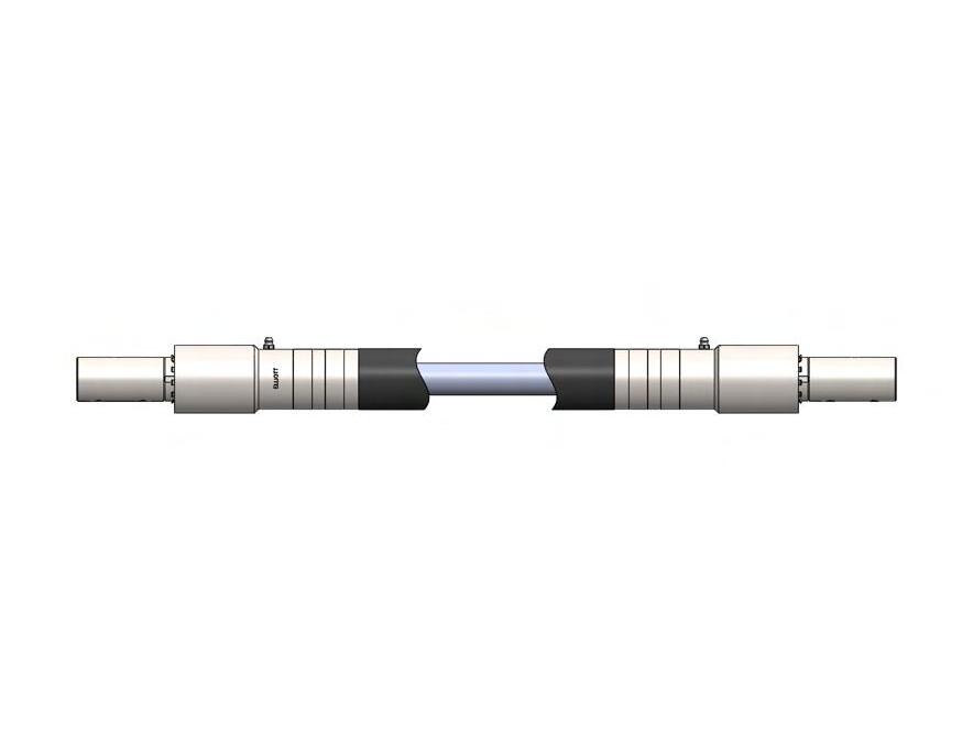
Speed 2000 rpm
Min Lgth. 26 in.
Max Lgth. 25 ft.
Min Bend Rad18 in.
Ref P/N 3708
15 KCP 06/19 B C Model Name:03696_B-411 D DATE APVD 1.000 FLEXIBLE SHAFT ASSEMBLY 3696 G REV DWG NO. SH 1 OF 1 (BALL BEARING UNIT) A B B C C D 1 2 SolidWorks 6 D
Max Lgth. 17 ft.
1 2 3 4 5 6 1.38 1.50 1.25 2.50 7.85* 1.47* .750* CORE .50 .750* C C D 1 2 3 4 5 6 D
Lgth. 22 in.
Max Lgth. 20 ft.
Bend Rad. 12 in.
Lgth. 20 ft.
Min Lgth. 26 in. Max
Bend Rad.
in. Ref P/N 3696 3.75 1.250* CORE 1.75 3.00 2.25 2.22* 10.73* 1.75 .750* 1.000* (*Nominal-Reference) B B C C D 1 2 3 4 5 6 D
15
(*Nominal – Reference) 1/2” DIA 3/4” DIA 1” DIA 1-1/4” DIA 5/8” DIA
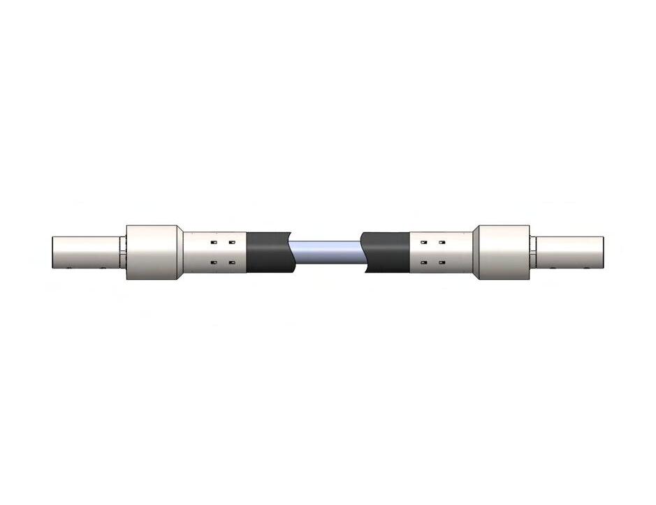
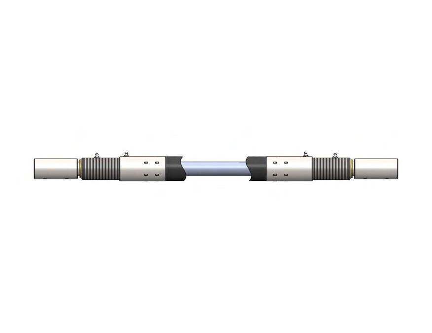
16 B C D 1 2 3 4 Model Name:S15310_B-400 5 6 D B C D 1 2 3 4 Model Name:S12779_B-401 5 6 D SH 1 OF 1 Elliott Flexible Shaft Assemblies–Bronze Bearing Units .312* .375* .500* .625* .88 1.62 5.37* 1.12 .97 .91* 1.13 .375* CORE (*Nominal-Reference) J ECN XXXX; SEE ECN SH FOR CHANGES; EWR 7628 JSM KCP 06/19 A B B C C D 1 2 3 4 Model Name:S12797_B-404 5 6 D SCALE: 1:1 APVD KCP 06/19 CHKD KCP 06/19 FINISH: DRWN 06/11 /19 JSM DATE APVD BY .375 FLEXIBLE SHAFT ASSEMBLY S12797 J ±5° ±.015 ±.003 ±.01 LTR REVISION REV B SIZE TITLE 72166 DWG NO. ID CODE CAGE NO. DATE MATL: UNS NO. REMOVE ALL BURRS & SHARP EDGES. TOLERANCES (EXCEPT AS NOTED) TWO PLACE DECIMALS SURFACE ROUGHNESS THREE PLACE DECIMALS FRACTIONS 63 ANGLES ALL DIMENSIONS ARE IN INCHES UNLESS OTHERWISE NOTED. 404 P.O. BOX 773 BINGHAMTON, NY 13902 DRAWING PREPARED IAW ASME Y14.5M-1994 SH 1 OF 1 Recommended: Speed 2000 rpm Min Lgth. 8 in. Max Lgth. 15 ft. Min Bend Rad. 4 in. Ref P/N S15310 Recommended: Speed 2000 rpm Min Lgth. 12-1/2 in. Max Lgth. 15 ft. Min Bend Rad. 8 in. Ref P/N S12797 Recommended: Speed 2000 rpm Min Lgth. 10 in. Max Lgth. 15 ft. Min Bend Rad. 6 in. Ref P/N S12785 Recommended: Speed 2000 rpm Min Lgth. 9-1/2 in. Max Lgth. 15 ft. Min Bend Rad. 4 in. Ref P/N S12779 SelfLubricating Bronze Bearings (*Nominal – Reference) 3/16” DIA 1/4” DIA 5/16” DIA 3/8” DIA
Recommended:
Speed
Recommended:
Speed 1500 rpm
Min Lgth. 22 in.
Max Lgth. 17 ft.
Min Bend Rad. 10 in. Ref P/N S12830
Recommended:
Speed 1200 rpm
Min Lgth. 23 in.
Max Lgth. 20 ft.
Min Bend Rad. 12 in. Ref P/N 3677
Recommended:
Speed 1000 rpm
Min
Recommended:
Speed 1000 rpm
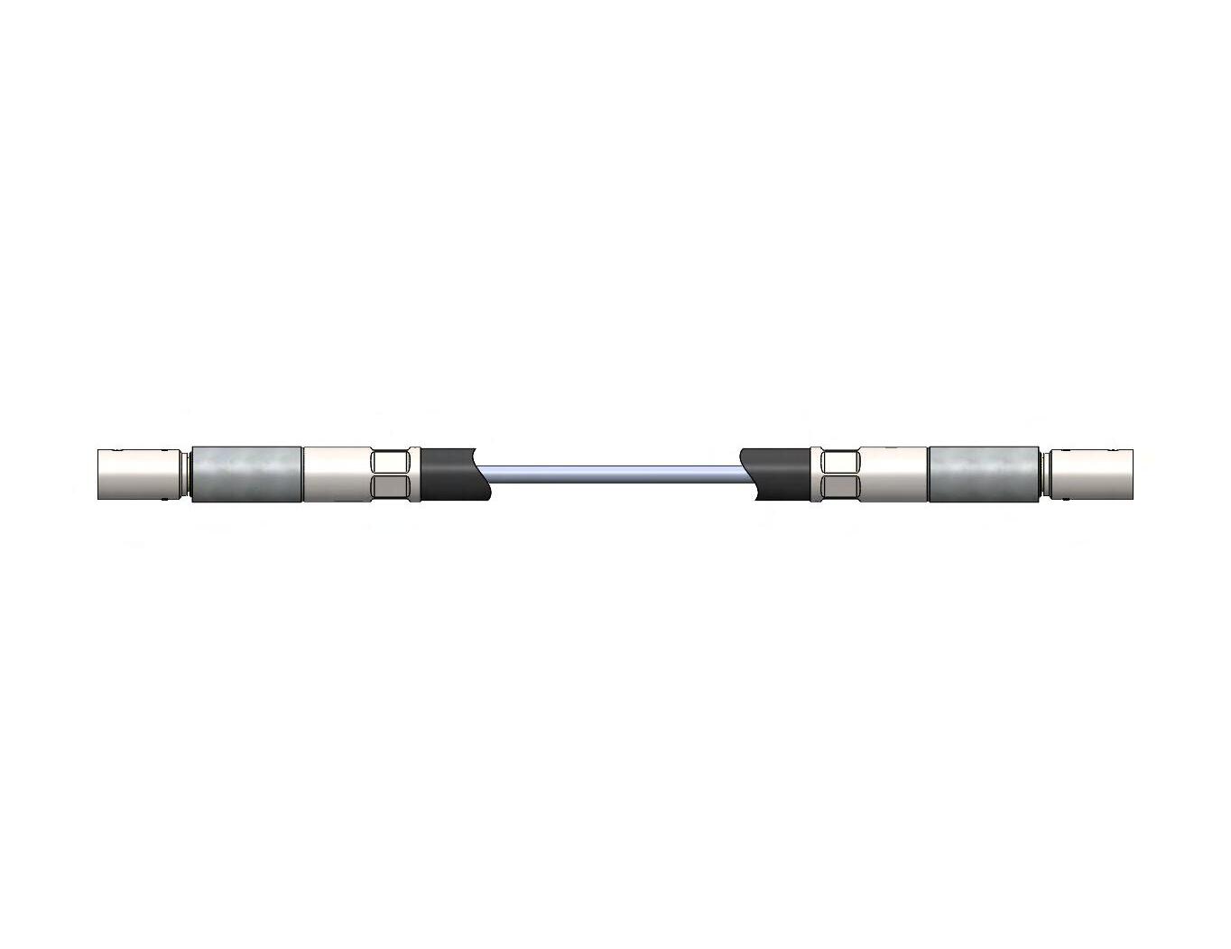
17 (*Nominal – Reference) KCP 06/19 B C Model Name:03695_B-411 D DATE APVD 1.000 FLEXIBLE SHAFT ASSEMBLY F REV SH 1 OF 1 (BRONZE BEARING UNIT) KCP 06/19 A B B C C D Model Name:S12813_B-407 SolidWorks D DATE APVD .500 FLEXIBLE SHAFT ASSEMBLY S12813 K REV DWG NO. SH 1 OF 1
Lgth. 17 in.
Bend Rad. 8 in. Ref P/N S12813 D 1 2 3 4 Model Name:S12830_B-409 5 6 .750* CORE 1.47* 1.62 1.50 .75 1.38 1.25 2.50 8.44* .750* 06/19 B C C D 1 2 3 4 Model Name:03677_B-410 5 6 D DATE APVD .750 FLEXIBLE SHAFT ASSEMBLY D REV SH 1 OF 1 (BRONZE BEARING)
2000 rpm Min
Max Lgth. 17 ft. Min
Lgth. 20 ft.
Min Lgth. 27 in. Max
Bend Rad. 15 in. Ref P/N 3695 4.00 12.07* 1.87 2.00 1.125* 2.25 2.22* 1.250* CORE 2.00 (*Nominal-Reference) B B C C D 1 2 3 4 5 6 D
Lgth. 27 in. Max Lgth. 25 ft.
Bend Rad18 in. Ref
Elliott Flexible Shaft Assemblies–Bronze Bearing Units 1/2” DIA 3/4” DIA 1” DIA 1-1/4” DIA 5/8” DIA SelfLubricating Bronze Bearings
Min
Min
P/N 3707
Elliott flexible couplings are an ideal solution for less demanding applications. The simple construction of fittings attached directly to the core and casing (when necessary) can offer a light, compact, inexpensive, and efficient solution to your flexible shaft needs.
FLEXIBLE COUPLINGS CONSIDERATIONS
When evaluating an Elliott flexible coupling for your application, follow all guidelines listed on pages 9-12 for determining core diameter along with length. Length can be a limiting factor when using flexible couplings with casing, as without casing the core has no support other than its own stiffness. Use the table to determine the maximum torque capacity for your flexible coupling. If you need increased torque capacity or are exceeding the maximum length for unsupported core, either specify casing or support the core as needed.
Elliott flexible shaft components are precisely manufactured to stringent specifications.
Did you know?
Standard sizes shown above. Custom sizes available. Contact Elliott Mfg. for details.
18
Standard Flexible
3/16 1/4 5/16 3/8 1/2 8257-202 8258-201 8258-202 8259-201 8259-202 8260-201 8260-202 8261-201 8261-202 8262-201 8262-202 .500 .500 .625 .750 .875 .251/.253 .188/.190 .251/.253 .188/.190 .251/.253 .251/.253 .313/.315 .313/.315 .376/.378 .376/.378 .501/.503 E .844 .844 .812 .906 1.062 1.344 1.438 .377 .378 .500 .625 .750 1/8 5/32 3/16 1/4 5/16 3/8 1/2 PD PD RC PD RC PD RC PD RC PD RC PD RC 2” 3.5 4.0 5.5 9.0 9.4 20.0 25.0 45.0 84.0 100.0 120.0 190.0 220.0 3 3 3.5 3.5 4.0 4.0 4.5 5 6 6 8 6 10 6” 1.0 1.4 1.8 2.6 3.0 6.4 8.0 12.5 24.0 37.0 45.0 88.0 97.0 4” 1.8 2.0 2.8 4.0 4.6 10.0 12.5 21.0 42.0 58.0 62.0 135.0 149.0 8” 8 1.0 1.2 1.8 2.2 4.2 5.8 9.2 18.2 28.0 32.0 64.0 70.0 10” 6 .8 1.4 1.6 3.5 4.4 7.2 14.0 18.0 24.0 47.0 52.0 12” 1.0 1.1 2.8 3.5 5.5 10.8 16.0 18.0 39.0 49.0 14” 2.2 2.9 4.5 9.0 13.0 16.0 32.0 36.0 16” 1.8 2.0 3.8 7.2 10.0 12.0 27.0 29.0 Maximum Torque Capacity (Static or Dynamic) for Given: Length of Unsupported Core Core Dia. Type Min. Rad. C E E FLEXIBLE SHAFT D D
Elliott
Couplings
LENGTH A
FLEXIBLE SHAFT CASING
An Elliott flexible shaft casing acts as a support and a bearing for the core, and protects the rotating element from moisture, dust, abrasion, and injury. Because of its construction, the casing also retains any lubrication surrounding the core. Casing selection is determined by a number of factors, including:
• Specific application requirements
• Operating conditions such as exposure to gasoline, grease, oil, or water
• Exposure to extreme heat
• Resistance to corrosion
• Severe twisting, flexing, or stretching
• Abnormal service where dust and abrasion are considerations
Elliott cores and casings are available in mill lengths or pieces cut to length, with or without ferrules and fittings. As part of our full service, we supply all needed information on cutting and assembling these parts to form your flexible shaft assembly.
SQUARED CORE ENDS
Squaring the end of the core is the simplest and least expensive drive for a flexible shaft. This eliminates the need for attaching a fitting and allows for the use of a smaller I.D. casing. Whenever possible, use a square end for optimal simplicity, savings, and reduction of solid length at the end of the core.
10589-2
10598-1
15611-3
15611-42
15611-19
15611-39
15611-5
15611-6
15611-37
15611-9
15611-28
6”-8” 6”-8”
6”-10”
9”-13”
12”-18”
12”-18”
8”-12”
8”-11”
8”-11”
Did you know?
Elliott uses a wide variety of the highest quality materials and finishes to provide you with flexible shaft assemblies and components that meet the demands of your application and provide a lifetime of reliable performance.
19 Need a custom flexible shaft solution? Contact us at +1 607-772-0404 or elliottmfg.com
.187” .250” .312” .312” .312” .375” .375” .500” .625” .625” .625”
Elliott Components
0.15 0.17 0.41 0.50 0.72 0.73 0.60 0.78 0.74 0.94 0.95 Hytrel Hytrel Elastomer Elastomer Elastomer Elastomer Elastomer Elastomer Elastomer Elastomer Elastomer .580” .655” .875” .890” 1.100” 1.090” .980” 1.150” 1.130” 1.370” 1.370” .265” .345” .400” .401” .432” .505” .545” .635” .682” .815” .825” Nominal Casing Casing Casing Loop Weight External Core Part I.D. O.D. Dia Per Covering Diameter No. Min. ± .30” Inches Ft. (lbs) Material .130 .150 .187 .250 .312 .375 .437 .500 .624 .101/.104 .121/.124 .147/.150 .196/.200 .245/.250 .300/.305 .350/.355 .400/.405 .507/.512 1.250 1.250 .781 1.375 1.375 1.500 1.500 1.500 1.750 .140 .161 .197 .268 .332 .400 .485 .540 .680 Core Diameter A B (Max.) C (Min.)
10”-14” 12”-16”
B C A
Did you know?
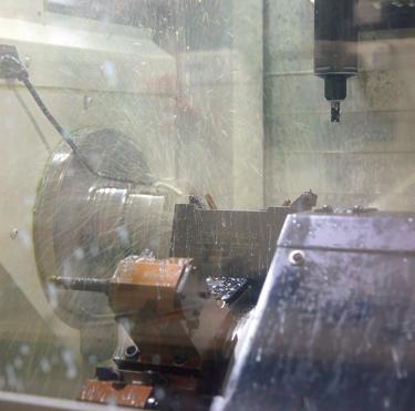
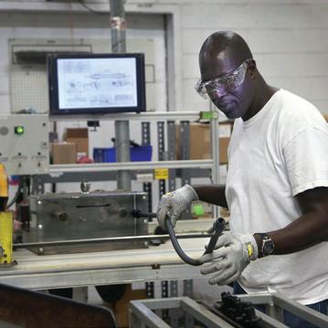
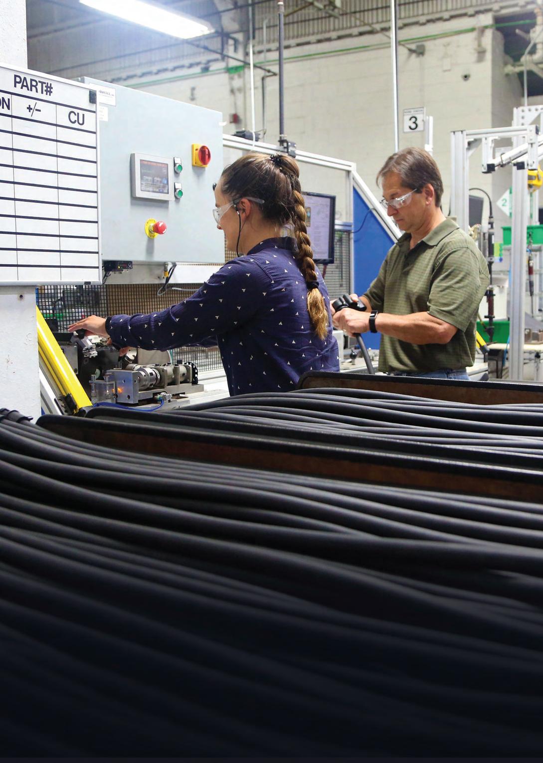
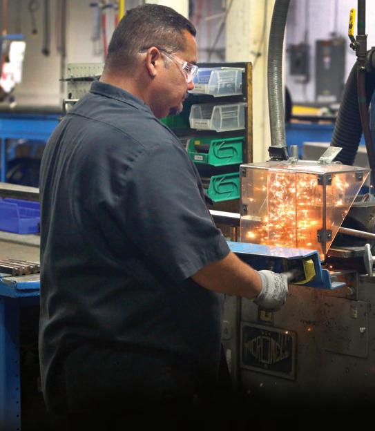
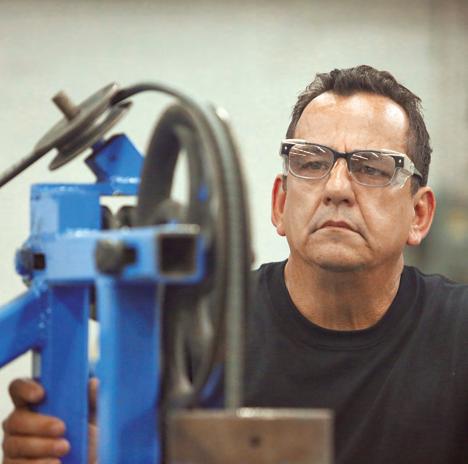
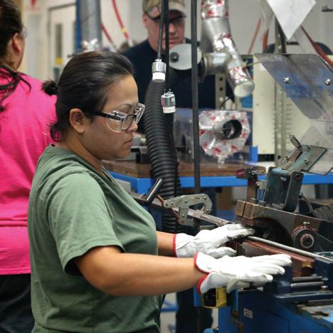
Leading-edge equipment and processes help ensure Elliott builds the best flexible shaft solutions available today.
20
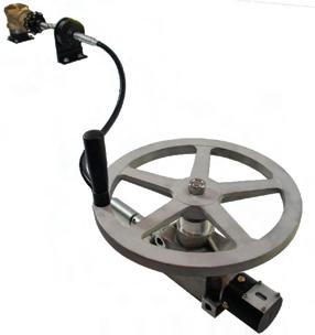
BUILT-IN WHEEL ARBOR
MODEL 50T TOOL SHAFT
REMOVABLE WHEEL ARBOR
x 1 x 1/2 I.D.
APPROXIMATE CALCULATIONS FOR WEIGHT OF FLEXIBLE SHAFTING (FORMULAS ARE FOR STEEL)
MODEL 38T TOOL SHAFT Core Casing
Interlocked Light-Weight Casing
Interlocked Standard Weight Casing
Interlocked Light-Weight with Liner Casing
Interlocked Standard Weight with Liner Casing
.202 x core dia.2 x length (in inches)
For description of casing, see pages 7 and 19
For I.D.s up to 1/2” | Weight = [(.027 x casing I.D.) + .002] x length (in inches)*
For I.D.s 1/2” and up | Weight = [(.023 x casing I.D.) + .002] x length (in inches)*
For I.D.s 1/2” and up | Weight = [(.052 x casing I.D.) + .007] x length (in inches)*
For I.D.s up to 1/2” | Weight = [(.055 x casing I.D.) + .006] x length (in inches)*
For I.D.s 1/2” and up | Weight = [(.064 x casing I.D.) + .007] x length (in inches)*
For I.D.s 1/2” and up | Weight = [(.097 x casing I.D.) + .018] x length (in inches)*
* Calculated weight of casing is for preliminary estimate only. Actual weight of casing will depend on weight of strip or wire from which casing is made.
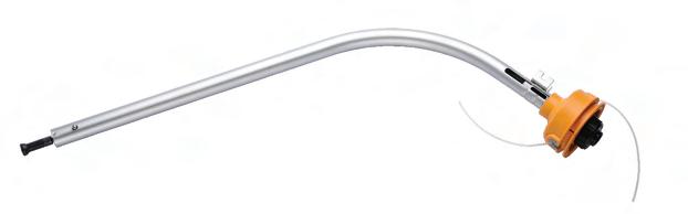
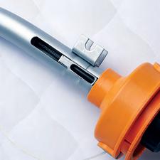
21 elliottmfg.com MOTOR CONNECTION HANDPIECE S06465-601 S06465-603 S06465-602 S06465-604 S06969-501 S06969-502 S06969-503 38 38 38 38 50 50 50 5 5 6 6 6 6 6 0.91 0.91 0.91 0.91 1.06 1.06 1.06 1/3 1/3 1/3 1/3 1 1 1 1/2 1/2 1/2 1/2 1-1/2 1-1/2 1-1/2 1/2 5/8 1/2 5/8 1/2 5/8 3/4 4 x 1 x 1/2 I.D. 4 x 1 x 1/2 I.D. 4 x 1 x 1/2 I.D. 4 x 1 x 1/2 I.D. 6 x 1 x 1/2 I.D. 6 x 1 x 1/2 I.D. 6 x 1 x 1/2 I.D. 6 x 1/2 x 1/2 I.D. 6 x 1/2 x 1/2 I.D. 6 x 1/2 x 1/2 I.D. 6 x 1/2 x 1/2 I.D. 6 x 1 x 1/2 I.D. 6 x 1 x 1/2 I.D. 6 x 1 x 1/2 I.D. 7” Dia. 7” Dia. 7” Dia. 7” Dia. 9” Dia. 9” Dia. 9” Dia. 3 Dia. X 1-1/2 Face 3 Dia. X 1-1/2 Face 3 Dia. X 1-1/2 Face 3 Dia. X 1-1/2 Face 5 Dia. X 2 Face 5 Dia. X 2 Face 5 Dia. X 2 Face 6 x 1 x 1/2 I.D. 6 x 1 x 1/2 I.D. 6 x 1 x 1/2 I.D. 6
x 1 x 1/2 I.D.
x 1 x 1/2 I.D. 1/4 Dia. 1/4 Dia. 1/4 Dia. 1/4 Dia. 3/8 Dia. 3/8 Dia. 3/8 Dia. Item # Shaft Size Length in ft. Case OD in. 1750
Max Horsepower Capacity in Inches
8 x 1 x 1/2 I.D. 8
8
RPM 3400 RPM Standard Motor Connection Bore in. Grinding Wheel Buffing Wheel Sanding Disc Sanding Drum Wire Brush Drilling Steel
If a standard Elliott component meets your application requirements, the information and charts in this handbook should allow you to make the proper selection. To order a standard flexible shaft assembly or coupling, determine the following:
1) Part Number
2) Core Diameter
3) Direction of Rotation
• PR = Right hand power drive
• PL = Left hand power drive, or
• RC = Remote control or bi-directional
4) Length
5) Bore Diameters (for flex shaft assemblies)
EXAMPLE
How to Order a Coupling
You want to transmit 20 in. lbs. at 1000 rpm (.32 hp) through a 6” flexible straight coupling.
1) Begin by determining your core size in the charts on pages 10 and 11. This is ¼”.
2) Next, use the chart on page 18 to determine the maximum torque capacity of a ¼” flexible coupling that is 6” long. This is 6.4 in. lbs.
3) Since this value is lower than required, you must either add casing or go to a larger shaft. This is 5/16” with a 24 in. lbs. capacity in a 6” length.
22 Ordering Standard Flexible Shafts
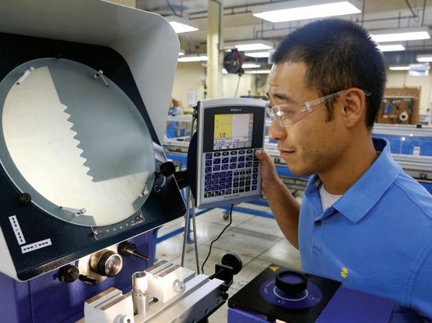
BUILT-IN QUALITY
At Elliott, we understand how critical the performance of our flexible shafts are to the integrity of your equipment and to the safety and productivity of you and/or your customers. Our highly skilled team has access to industry-leading quality software and tools, best practice processes, and the latest field and lab testing capabilities to make sure you receive the best flexible shafts available today.
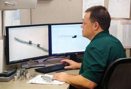
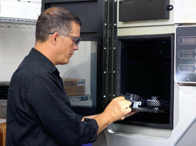
CUSTOM SOLUTIONS
Elliott custom flexible shafts are designed to meet the exact requirements of your application. Using advanced design tools, 3-D modeling, state-of-the-art analysis, and rapid prototyping, our experienced engineers will work with you to develop a timely, cost-effective, efficient, and reliable solution to your power transmission challenges — no matter how demanding they may be.
Did you know?
Elliott Manufacturing is ISO9001:2015 and AS9100D certified.
What problem can we solve for you?
Need a custom flexible shaft solution? Contact us at +1 607-772-0404 or elliottmfg.com
Custom Solutions
Elliott
23
Elliott offers standard and custom flexible shaft solutions for just about any application.
Global Locations
Elliott Mfg. USA
11 Beckwith Avenue
Binghamton, NY 13901
Tel: +1-607-772-0404

Elliott Mfg. Mexico
Calle Neptuno No.1917
Complejo Ind. Saragoza No. 3
Col. Satelite C.P.32540
Cd. Juarez, Mexico
Tel: +1-915-791-0005 (from U.S.) +011-52-656-687-0905 (in Mexico)
Turotest Medidores Ltda
Avenida Luiz Merenda, 489 - Campanário
Diadema-SP - CEP: 09931-390
Tel: +55 (11) 4092-7200


For a custom flexible shaft solution, contact +1-607-772-0404 or elliottmfg.com © Elliott Manufacturing 2024 | All rights reserved. EM0101008-0224
elliottmfg.com Scan the QR code to learn more.
