
WALL SYSTEMS
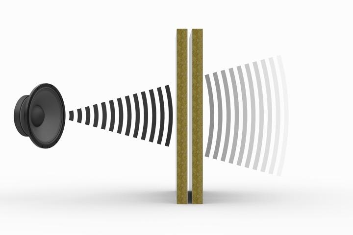
Norac’s wall systems are designed to meet the following criteria: quality, flexibility, fire, sound, weight and ease of installation. Based on new requirements for improved acoustic insulation, Norac has developed a series of acoustic walls, which offer documented sound reduction properties of up to 54 dB RW.
WALLS K- 600
K-600 is designed with integrated joint profiles for rapid installation, leaving a flush surface with single seam joints. Available in standard or modular system.
Approved B-15 available for several wall types.
The system have been shock tested. More information available on request.
K-panels are also available in aluminium construction in B-15 with considerable weight savings.
See technical descriptions below.
All weights are based on system weight, including all profiles

WALLS Q - 600 / CF - 600
Q-600 is acoustic wall system of sandwich construction with an excellent sound reduction quality.
Q-600 is a rigid system with integrated joint profiles which allows for easy and rapid installation.
Flush surface with single seam joints. Available as a modular system.
50 mm panels available with vertical cable ducts in B-15.
70 mm panels have the possibility to draw cables horizontal and vertical.
All weights are based on system weight, including all profiles


WALLS K / CONNECTING DETAILS


and studs
NOTE: Norac systems are delivered with a wide variety of connecting elements/profiles to obtain the best solutions. Corners may be delive red in stainless steel finish.
Flush corner connection with stud 25 mm
Flush corner connection with stud 50 mm
Rounded corner with stud
Flush T-connection with panels
WALLS K / CONNECTING DETAILS


NOTE: Norac systems are delivered with a wide variety of connecting elements/profiles to obtain the best solutions. Corners may be delive red in stainless steel finish.

Flush U-profile
Profile for cut mounting
Corner for cut mounting
Rounded corner
WALLS C- 600 / CS - 600
C-600 is an acoustic double wall system with two independent wall elements installed in the same profile system.
Available as standard or modular system.
Allows installation of electrical cables before completing assembly (in 70 mm version).
All weights are based on system weight, including all profiles


WALLS C / CONNECTING DETAILS


NOTE:
Norac systems are delivered with a wide variety of connecting elements/profiles to obtain the best solutions.
Corners may be delivered in stainless steel finish.
WALLS CSG - 600 / 70
The use of additional insulation between the two panels of a CS-600/70 wall improves the sound reduction by an amazing 4dB compared to the CS system on page 15.
Note that building thickness is not more than 70 mm.
All weights are based on system weight, including all profiles


WALLS ADDITIONAL PANEL CONCEPT
Additional panel concept for installation on existing walls. Ideal for refurbishing purposes, and where a better sound reduction between cabins is required. Thickness 20 mm only.
All weights are based on system weight, including all profiles
Depends on existing wall

WALLS REMOVABLE PANELS
To be used where access is required. C-class.


WALLS REINFORCEMENT
Built in reinforcements to accommodate heavy wall hung equipment, such as wash basins, TV-brackets, pullman beds etc can be delivered upon request. Various solutions available.

Special reinforcement for Pullman beds, single or double


WALLS LOADBEARING CAPACITY
STRENGTH OF HAND RAILS ATTACHED TO WALL PANELS
The tongue and groove system allow fixing of heavy objects to the wall without special reinforcement.
Both K-600/25 mm and K-600/50 mm are qualified according to the SOLAS regulation: “Strength test for B-class panels to which handrails are attached on RO-RO passenger ships”.
The result can be transferred to other Norac panel types. The full report is available on request.
GENERAL STRENGTH PROPERTIES
Norac have performed several series of other tests on strength properties. More information is available on request.
The below fixing methods and specifications will not impair the fire integrity of the panel types subject to the delivery.
ATTACHMENT WEIGHT
(MAX PER PANEL PER FACE) [KG]
EQ TO BE INSTALLED BY… FIXING METHOD FIXING ITEMS AND DRIL HOLES
W < 20
CoG of EQ < 150 mm
From wall surface
Mechanically attached directly to the wall without reinforcement.
Fix with screws with bonded washer. Min. 4 screws separated from each other by minimum 250 mm.
20 ≤ W ≤ 80
CoG of EQ < 150 mm
From wall surface
Mechanically attach directly to reinforced wall. Reinforcement to be provided to the wall by NORAC. Wall elevation with EQ location to be issued to NORAC
W > 80 Item should not be attached to the wall. Separate stand to be provided.
Fix with screws with bonded washer. Min. 4 screws separated from each other by minimum 250 mm.
On face sheet:
Drill Holes = 3.0 mm
Screw size = D5x30 and Fisher A5 dowels
On vertical joints: Drill holes = 2.7 mm
Screw size = D5x30
On face sheet:
Drill Holes = 3.0 mm
Screw size = D5x30 and Fisher A5 dowels
On vertical joints: Drill holes =2.7 mm
TBD item by item
TBD item by item
Equipment attached to B-rated wall
WALLS HORIZONTAL JOINT
For areas where ceiling height exceeds 3000 mm. Used for linings only.
Connection to steel bulkhead is yard’s supply.


WALLS CABLE DUCTING
Pre-arranged duct and cut-outs for cables and sockets can be delivered upon request. Tested with up to 10 ducts per 600 mm panel as B-15 class.
Standard size of conduit:
• Single 20x30 mm
• Double 20x60 mm

WALLS PANELS FOR WET SPACES


Detail for wet room – 25 mm lining only
on flat bar supplied by yard. Standard thickness of flat bar 8 mm.
50 mm panels with symmetric finish
50 mm panels with asymmetric finish
Mounted
WALLS WET COAMING


A specially designed wet coaming used on top of floating floors in wet areas. The coaming is a fully insulated galvanized ste el profile. It is secured to the floor with self tapping screws or rivets.
Height of coaming according to customer request. Can be delivered in galvanized steel and stainless steel.
Coaming for 25 mm wet panel
Coaming for 50 mm panels wet / wet
WALLS INSPECTION DOORS AND HATCHES
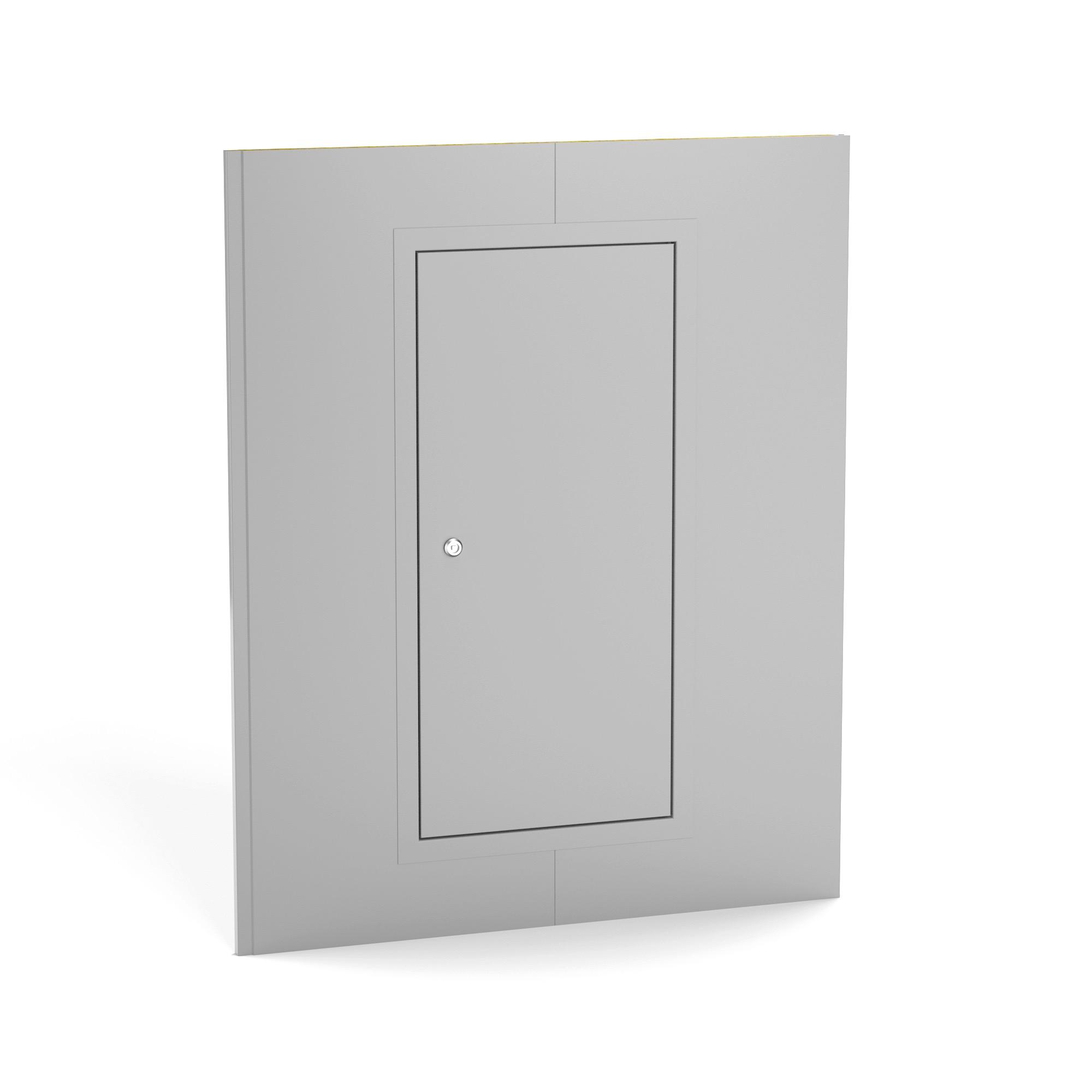
For quick access to technical spaces such as pipe connection, electrical boxes etc.
The surface is normally the same as the wall to give a discreet finish.
Square key-lock or handle is optional.
Available with custom print.
DESCRIPTION INSPECTION DOORS WALL HATCH Fire class B-15 B-15
Surface PVC, paint, stainless steel PVC, paint, stainless steel
Core material Rockwool Rockwool
Max clear opening 800 x 2100 mm 500 x 1500 mm
Thickness 20 mm 20 mm
Weight 19 kg/m²-approx 19 kg/m²-approx

hatch
Lock 3-point square lock* 3-point square lock * Can be delivered also in triangle lock and recessed ring handle

door
Inspection
Inspection
WALLS INSPECTION DOOR / TECHNICAL DETAILS


WALLS INSPECTION HATCH / TECHNICAL DETAILS


WALLS EXAMPLE OF STANDARD SYSTEM
A standard system is a flexible system allowing adjustments onboard the vessel during construction. The panels are delivered in one standard size and are cut to fit according to the on-site measurements with use of stand profiles.
Profiles are designed to leave as few visible screws/rivets as possible.
Norac can provide a Drawing Package upon request. The Drawing Package consists of Norac products, elements, and profiles, and can be used by the recipient for information of the Norac product system. It can also be used by the recipient for generating material takeout’s (MTO).
Norac can deliver product, elements, and profiles according MTO by customer.
The elements and profiles in the drawing package are standard products. NORAC can also design and produce special elements and profiles according to customers need.

WALLS EXAMPLE OF MODULAR SYSTEM
A modular system is a fully tailor-made system to avoid adjustments and cutting onboard vessels. These systems reduce waste and the installation time for the yard and most importantly, reduces costs.
A modular system leaves a smooth finish with no external profiles and no visible screws/rivets.
It is appreciated just as much for commercial vessels and offshore rings as it is for cruise vessels.
For modular and semi-modular wall- and ceiling systems, Norac provides engineering according to customers General Arrangement (GA) drawings. NORAC engineering generates installation drawings and will ensure an optimal solution.


No: K-625401

Standard 25 mm adjustment profile flush


No: K-625010
WALLS PROFILES


No: K-6258xx 25 mm bent adjustment profile cut
No: K-6508xx 50 mm bent adjustment profile cut

No: K-600020 Start/stop profile


WALLS PROFILES


25 mm rounded corner element cut

25 mm bent corner element cut


50 mm bent corner element flush

6256xx
No: K-6507xx
No: K-625062
OUR OFFICES
NORAC AS (head office)
Kystveien 18, 4841 Arendal, Norway
Phone: +47 37 05 92 50
Mailing Address:
Postbox 1593 Stoa, 4847 Arendal, Norway
www.norac.no
UAB NORAC AS
Pramones g.3, LT-35289 Panevezys, Lietuvos
Phone: +370 45 443602
NORAC SUZHOU LTD.
Jin Wang Road No.2
Xu Guan Town
Suzhou New District, China
Tel: +86 512-6575 6299
Cel: + 86 18915598797
P.C: 215151
www.norac.com.cn
CHINA
Suzhou
LITHUANIA Panevezys
NORWAY Arendal

Norac’s head office in Arendal, Norway.
