

AMMONIA FOR LIFE
Through the eyes of experts: a journey into the history of the ammonia industry
THE SYNTHESIS OF AMMONIA AND THE BIRTH OF MODERN CHEMISTRY
© 2021 All rights reserved
CASALE SA SWITZERLAND
Via Giulio Pocobelli 6
6900 Lugano Switzerland
Phone +41 91 641 92 00
Fax +41 91 641 92 91
www.casale.ch
info@casale.ch
Francesco Baratto, Luca Bianchi, Vittorio Cariati, Ermanno Filippi, Raffaele Ostuni, Sergio Panza, Fabio Sassi, Elio Strepparola

Table of contents

foreword
Venkat Pattabathula
Ammonia is one of the most important synthetical chemicals produced globally, with approximately 85% being used in the manufacture of fertilizers.
The development of the ammonia production technology ultimately led to the growth of the world population from about one billion in 1900 to about eight billion nowadays. It has been stated that a world without synthetic fertilizers would only sustain a global population of about four billion.
Fritz Haber, an industrial chemist, and Carl Bosch, a chemical engineer, have been named among the world’s most influential scientists of all times. The German duo were responsible for what, perhaps, is the most recognized chemical process in the world, to capture nitrogen from the air and convert it to ammonia. While Haber developed a high-temperature, 450°C, high-pressure, 300 barg process to break the triple bonds of atmospheric nitrogen, Bosch was responsible for scaling it up, finding cheaper ways of producing hydrogen, developing a new catalyst iron-based catalyst, designing and building a reactor that could withstand both the temperature and pressure requirements of the reaction.
In 1913, BASF (Badische Anilin und Soda Fabrik) began operating the world’s first commercial ammonia plant in Oppau, Germany. The initial plant capacity was 30 tpd of ammonia. Coal and coke were used to produce steam and coke oven gas which was purified and compressed ahead of ammonia synthesis.
In 1919 Luigi Casale, an Italian engineer with practically no personal financial resources, succeeded in convincing a metallurgical company in Terni (Idros) to set up a 100 kg per day pilot ammonia plant in its factory using his patented ideas.
Luigi Casale, helped by his wife Maria Sacchi, quickly succeeded in making the pilot plant work well thanks to the simplicity of its flow scheme.
By 1923, Casale technology had been adopted in Italy, Germany, France, Japan, Switzerland, Spain and the USA with more than 15 plants producing altogether about 800,000 tonnes of ammonia per year. Expansion continued at a rapid pace and by 1927, the year of Luigi Casale’s sudden death, the process was utilized in Belgium, England, and Russia with an overall global ammonia capacity of 320,000 tpy.
The production of ammonia has changed over the past 110 years. Some of these changes have been dramatic, such as the production of synthesis gas. Yet, in all these developments, the ammonia synthesis loop has essentially remained the
same as Haber and Bosch devised it. From humble beginnings, the production of ammonia has grown from very low production rates to more than 180 million tpy in more than 70 countries. This growth would not have been possible without the development efforts over the years by many process technology licensors.
Since BASF started producing 30 tpd of ammonia nearly 110 years ago, technology developments in all aspects of the ammonia production process have been realized so that plants producing more than 3000 tpd are operating today.
This book will give the reader a complete picture about how the ammonia technology has evolved since its inception in addition to the biography of 10 key veterans who played a major role in the development of ammonia process technology.

Vittorio Cariati
From the time of our species’ earliest appearance on earth, currently thought to have been about 200,000 years ago, the total population of anatomically modern humans (Homo Sapiens) took until the early years of the 19th century to reach one billion, but only about another 100 years to reach two billion, and then a mere 30 more years to reach three billion; by 2016 it had risen to an almost incredible 7.4 billion people. This means that around 6.5% of all human beings that have ever lived are alive today.
For most of that 200,000-year history, humankind was essentially a nomadic hunter-gatherer, a lifestyle not conducive to substantial population growth, particularly during glacial periods which limited its habitation range. At the start of the current inter-glacial period about 12,000 years ago, the increase in the earth’s temperature led to the development of vegetation similar to that of today. It was then that humans started to learn how to cultivate various species of edible plants and to domesticate the most common animals. This allowed them to put down roots in settled communities and to develop other recognised elements of what we now call civilisation. This seems to have happened initially as a result of the natural evolution of common wheat in an area known as the Fertile Crescent, covering the Levant, Mesopotamia (the area between the Tigris and Euphrates rivers in what is now Iraq), and the Nile valley in Egypt; but in the succeeding millennia civilisations formed separately and independently in other parts of the world, including the island of Crete, the Indus valley, Mexico, Peru and China.
The farmers of Mesopotamia soon learnt that the fertility of the land depended on the use of water from the two rivers but, even so, yields decreased gradually and it was necessary to move from time to time to virgin land. They also learnt that plants grew better in ground on which organic and plant waste had been dumped, and when successive crops were different from their predecessor. Of course, the explanation for these effects was totally unknown at the time.
The rapid acceleration in the rate of population growth in the last 200 years is attributable mainly to a spectacular increase in life expectancy. That, in turn, is due to advances in medicine, nutrition, hygiene and sanitation. The most fundamental factor, without which all others would be of little effect, was and still is the growth in food supply resulting from improvements in the productivity of agricultural land. It is no coincidence that the upturn in population growth began initially in Europe in the 18th century with the introduction of efficient, scientific methods of crop rotation (a technique that, as noted above, had been practised for centuries but only empirically) and received a further boost in the latter half of the 19th century after pioneers such as Justus von Liebig had formally demonstrated the importance of inorganic nitrogen, phosphorus and potassium in plant nutrition and the superiority of mineral fertilizers containing them over traditional organ-
ic manures. The first fertilisers used were natural products rich in these elements: Chilean saltpetre from the Atacama Desert for nitrogen, guano from Peru for both nitrogen and phosphate, and wood ash and vinasse for potassium. But the sources of Chilean saltpetre and guano were extremely remote from all their markets and, as fertilization practice became more widespread, the supply of all of them quickly became a problem. Potassium supply was supplemented by the advent of potash mining in the late 19th century, and thanks to the development of superphosphate it became possible to exploit the phosphate content of bones and phosphatic minerals found in various parts of the world. But nitrogen – the nutrient that is actually needed in the largest quantities – was another matter. Because of the activity of chemically combined nitrogen, the Atacama was one of the only places in the world dry enough for inherently reactive nitrate minerals to have survived in nature in any quantity, and although ammonium sulphate had also become available as a by-product of town gas production in the industrial economies in the latter half of the 19th century, it was never going to be able to fulfil the growing demand for fertilizer nitrogen even locally, let alone globally.
So the race was on to find a way of transforming elemental nitrogen from the atmosphere, which contains the overwhelming majority of the world’s total nitrogen resource, into chemically fixed forms suitable for fertilizer use. The most desirable target, on account of its product’s potential for conversion to downstream products, was direct synthesis of ammonia from its elements, but this proved elusive: early experiments produced such vanishingly small yields that it was completely impractical as an industrial process. Two other nitrogen fixation process routes actually beat ammonia synthesis to commercialisation at more or less the same time: direct oxidation in an electric arc to nitrogen oxides, which could be worked up into nitric acid and nitrates; and reaction with calcium carbide to produce calcium cyanamide. The latter product could be hydrolysed (decomposed by the action of water) to form ammonia, and it was soon also used directly as a fertilizer, since it undergoes the same hydrolysis in the soil. But both of these nitrogen fixation methods consumed a lot of energy and, although cyanamide production continued on a small scale for around a century, within a few years a catalyst for the ammonia synthesis reaction had been discovered which was both effective and affordable, rendering both the earlier fixation routes effectively obsolete. The advent of industrial ammonia synthesis marked the point at which chemical engineering became ‘high-tech’ and the modern nitrogen fertilizer industry was born, opening the way to enormous increases in food production and, in turn, an unprecedented rise in the rate of population growth. It also sparked the growth of other industries such as explosives, dyes, resins, fibres and pharmaceuticals manufacture that contributed in various ways to the economic welfare of the growing
population, although it has to be admitted a less creditable aim of the quest for nitrogen fixation was to enhance the supply of munitions for a number of wars being fought by the imperial powers of Europe against each other and in their overseas territories. Nonetheless, no other single development in chemical technology comes close to that of ammonia synthesis in its beneficial impact on the human race. It would be no exaggeration to say that ammonia synthesis is to industrial chemistry what the lever is to mechanics.

CHAPTER 1 NITROGEN: NATURE AND MANKIND
Vittorio Cariati
The birth of the Universe
Today most scientists believe that the universe originated from an explosion of immense size, the Big Bang. According to this theory, prior to the explosion, all the energy and matter in the known cosmos was compressed into a tiny, single point, of an almost infinite density and at a temperature of billions and billions of degrees.
At the time of the explosion, traced by experts almost unanimously to 13.8 billion years ago, the temperature was about 100 billion degrees Celsius. At such a high temperature all matter was in the form of subatomic elementary particles. Because of their tremendous speed, approaching the velocity of light, these particles clashed incessantly and violently, thus having a very short life. With the gradual cooling the Universe reached approximately 2500°C and the first atoms were able to be formed and, as time went on, all the stars and planets of our universe originated, including the Sun and the Earth.
The Formation of the Solar System
The Sun was formed about 5 billion years ago and, like other stars, it originated from a mass of dust and gas, basically consisting of hydrogen and helium. The huge cloud that later was to become the Sun condensed gradually as the hydrogen and helium atoms were attracted to the centre of the cloud through the force of gravity, colliding with each other. The gases became warmer and with increasing temperature collisions became more and more violent until the hydrogen atoms began to collide with such force as to fuse their nuclei, forming helium atoms and releasing nuclear energy.
These thermonuclear reactions still take place inside the Sun and are the source of the energy that radiates from its turbulent surface.
The planets of the solar system were formed successively by gas and dust moving around the newborn star; these clusters attracted through gravity a large quantity of particles in this way giving rise to the planets. It is estimated that they were all formed, including the Earth, about 4.6 billion years ago.
The Earth
As time passed, however, planet Earth began to cool slowly, starting from the surface, thus giving rise to the outer crust: the oldest rocks of this layer, dated by the method of radioactive isotopes, are found to have originated about 4 billion years ago. An inner core of very dense material gradually formed, composed essentially of iron and nickel. The primitive atmosphere on Earth was formed, as on the Sun, mostly of hydrogen and helium. These two elements were dispersed rapidly in space. In later times, a second type of atmosphere was created, very different
from both the original and the current forms. This resulted from the enormous amount of gas evolved during volcanic eruptions. It stimulated the emergence of living things.
The appearance of life
The oldest traces of life which appeared on the planet Earth were found in sedimentary rocks of the Australian continent and in southern Africa. The actual appearance of life, however, is to be ascribed specifically to about 4 billion years ago.
The intense volcanic activity profoundly transformed the primordial atmosphere by emitting methane, ammonia and sulphudric acid. The water that flowed from the geysers enriched the atmosphere with steam. With decreasing temperature these clouds of steam condensed and formed the first warm, shallow oceans.
Initially a series of photochemical reactions led to the formation of urea, formaldehyde and hydrocarbons and, subsequently, of amino acids, sugars and nitrogenated bases which constitute the DNA chain, responsible for the transmission of hereditary qualities.
Scientists believe that these compounds accumulated in the oceans through a continuous process characterised by a long series of accidents, particularly during bolts of lightning, leading to formation of tiny spherical structures, the ancestors of the biological cell. The first traces of life, as primitive cells, appeared on Earth by spontaneous self-aggregation of the molecules in the primordial soups that were the early seas. The presence of energy sources such as ultraviolet radiation (the ozone layer had not yet formed), lightning from thunderstorms, and radioactivity meant that water constituted the ideal environment in which the first living systems could organise themselves and develop. From the first steps towards life as we know it, cellular organisation and reproduction led to a rich diversity of organisms.
Ultimately, from the formation of the Earth to the appearance of the first living cells, similar to current bacteria, there was a gap of more than a billion years!
Cyanobacteria
In 1956, geologist Phillip Playford, when diving off the coast of Australia, came across incredibly large limestone aggregations that had grown in shallow, warm, clear waters. These “stromatolites” are regarded by scholars to be extremely important because they represent the oldest traces of biological activity discovered to date. The aggregations were probably the first photosynthetic organisms to evolve through chlorophyll-based photosynthesis, converting light energy from the sun into chemical energy for assembly of complex molecules such as sugars, with ac-
companying release of oxygen. They also had the ability to undertake atmospheric nitrogen fixation, that is to transform the unreactive (inert) gas nitrogen into the highly reactive ammonium ion (NH4+) that combined with nitrogen oxides produced, albeit in very small quantities, during lightning and thunderstorms.
Chlorophyll photosynthesis
Chlorophyll-based photosynthesis was substantially the primary production process for organic compounds from carbon and inorganic substances on early Earth, and is the only biologically important process capable of collecting the solar energy on which life on Earth depends. The photosynthesis to give the carbon source of organic compounds of living organisms is represented by the basic reaction:
From the time when cyanobacteria first appeared, the atmosphere of our planet was gradually transformed, eventually achieving its current composition. Over billions of years the oxidizing atmosphere has deeply influenced the history of our planet because, from the breakup of carbon-containing compounds, such as CO2, it was possible to generate greater amounts of energy. which allowed, over time, the development of increasingly active and increasingly advanced organisms.
After the very slow beginnings of primitive single-cell life forms, it is thought that their transition to multicellular forms was much faster, as evidenced by the numerous findings of multicellular organisms dating from just 600 million years ago. During this geologic era, known as the Cambrian, life seems suddenly to have accelerated its transformation into the more complex systems that exist on Earth today. Multicellular organisms became endowed with resistant parts such as shells and skeletons, and multiplied in number. Living forms settled everywhere, occupying gradually all environments, moving from the waters of the oceans to the growing land mass, and colonising it.
The birth of mankind
It is recognised that modern Man, scientifically termed as “Homo Sapiens Sapiens”, descended from primates (including humans and monkeys) who about 4 million years ago split into two subclasses, namely anthropomorphic apes and hominids, the latter characterised mainly by their upright position. This was critically important since it allowed the hominids to have their hands free so they could be used to grab objects, collect food, and defend themselves from wild animals by throwing
6CO2 + 6H2O + light -> C6H12O6 + 6O2
rocks and stones. Achieving the upright position was therefore a very important stage in the evolution of Man.
Another important characteristic of hominids was that of the opposable and rotatable thumb, which could therefore be brought towards every other finger of the hand in order to enable the latter to close perfectly and grab objects.
Subsequently, around 2 million years ago, the hominids, in turn, were split into two classes, the so-called one of Australopithecines, that eventually became extinct, and that group globally labelled as “Homo.” Chronological differentiation of the “Homo” class have led us to define: ‘’Homo Abilis” (two million years ago),”Homo Erectus“ (1.5 million years ago), “Homo Sapiens”, (200,000 thousand years ago ), and finally the current “Homo Sapiens Sapiens” (35,000 years ago).
“Homo Sapiens” has long struggled with similar species for its survival and it is thought that it replaced “Homo Neanderthal”, a species of both European and Asian origins, also born from “Homo erectus”, around 150-200,000 years ago, and which coexisted with Homo Sapiens up to 24,000 years ago.
In more recent times, approximately 12,000 years ago, our species were forced to combine breeding with hunting. About 10,000 years ago, with the end of the last glaciation and the invention of agriculture, the Neolithic revolution was triggered. Access to stable food resources encouraged the formation of permanent communities, the domestication of animals and the transition from stone tools to the far more functional metal ones. So hunter-gatherer man became a livestock breeder-farmer.
Primitive man had a very different appearance from ours. The body was shorter and more bent than ours, the forehead quite narrow, the orbits protruding, the jaws very strong with large teeth that allowed him to chop up the roots of plants and raw meat.
Primitive man was certainly more robust and muscular than modern man but was weak compared to many animals. Nevertheless, man (and woman) survived and evolved over time, creating great civilisations: all thanks to the intelligence that allowed him to increase his knowledge, invent instruments of work, improving them continuously, devise means of transport, weapons, and so on.
The Presence on Nitrogen on Earth
Nitrogen (N) was discovered independently by C. W. Scheele in 1770 and by D. Rutherford in 1772, although Rutherford was the first to publish his discovery. The name is derived from the Greek and means “nitre former” on account of the characteristic presence of the element in the mineral of that name (naturally-occurring
potassium nitrate or saltpetre). The alternative name “azote”, by which nitrogen is known in France, and similar names in some other languages are also Greek-derived: they mean “without life” on account of the suffocating nature of air from which the oxygen has been removed. But in various combined forms nitrogen is, in fact, absolutely essential to all known life forms.
Elemental nitrogen is a colourless, odourless, gas which is very unreactive because it occurs in nature in the form of diatomic molecules (N2) in which the two atoms are held together by a highly stable triple covalent bond. This means that the chemical energy and thus the reactivity of elemental nitrogen are very low; in fact, nitrogen is the least chemically reactive element after the noble gases. It also means that the chemical energy of its compounds are always higher than that of the element itself; they therefore tend sooner or later to undergo energy-releasing reactions in which the nitrogen content reverts ultimately to the diatomic form. That is why the vast majority (about 75%) of Earth’s total nitrogen complement resides in elemental form as diatomic molecules in the atmosphere, of which it constitutes about 78% by volume. It is also why exploitable deposits of naturally-occurring nitrate minerals are extremely rare, even though continental crustal rocks are estimated to contain around one third as much nitrogen as the atmosphere does, but in a highly dispersed form. [1]
Nitrogen is present, albeit in small quantities, in every living cell. Proteins, the very stuff of living tissue, and enzymes (specialized proteins which perform or control vital biochemical processes within all kinds of organisms) comprise long chains of amino acids, each of which contains at least one nitrogen atom. Every molecule of chlorophyll, the green magnesium-based organometallic pigment which allows plants to capture the energy of visible light and use it to synthesize carbohydrates, is held together by four nitrogen atoms. Nucleotides, the basic structural units of the nucleic acids (DNA and RNA) which store and manage every organism’s genetic information, all contain nitrogen. As the biologist Arthur Needham noted, every vital phenomenon is due to some change in a nitrogen-containing compound, and especially the nitrogen atom(s) of that particular compound. Yet in spite of its vital biochemical importance, fixed nitrogen in the biosphere amounts to little more than a millionth of the total nitrogen content of the atmosphere, continental crust and ocean sediments. [1]
The Natural nitrogen fixation pathways
Animals create their own proteins by rearranging the amino acid units in proteins ingested in their diets; they cannot synthesise the amino acids themselves. In contrast, the amino-acids from which proteins are made can only be synthesised by
plant life. With the exception of a very limited number of bacteria, plants do not get the nitrogen they need directly from the atmosphere; they rely on an external source of chemically combined nitrogen. In effect, that usually means the soil, from which they absorb nitrogen as the nitrate ion (NO3-) or as the ammonium ion (NH4+).
The ability to assimilate atmospheric nitrogen directly is shared between a relatively small number of types of bacteria, some of which live in the sea and others in the soil. Of the soil-based bacteria some (though not all) can only function in symbiosis with the roots of leguminous plants.
For gaseous nitrogen to react with other substances, the valence bonds uniting the two atoms in the nitrogen molecule must first be disrupted, which requires a very large input of energy. In that state the nitrogen atoms are very reactive, but they will simply recombine with each other unless another atom, or molecule of a different substance, intervenes before that can happen. What this means is that only a small proportion of activated nitrogen atoms will be converted into chemically combined forms.
In nature there are only two known non-biological sources of energy of sufficient intensity to activate atmospheric nitrogen to the point where it will react. Because they both occur in the atmosphere the dominant product is nitrogen oxides, which are formed by direct combination with atmospheric oxygen. One is combustion, particularly of highly calorific materials such as fossil fuels, and thus, for the past two centuries, it is mainly anthropogenic. The other is lightning. The nitrogen oxides formed by the action of lightning mostly react with further oxygen and moisture in the atmosphere to become nitric acid, in which form the nitrogen is carried to the surface through precipitation. The combustion-generated nitrogen oxides are mostly formed at or near ground level and can present health hazards either directly or, through reaction with other atmospheric pollutants, as a group of harmful substances.
On the basis of most people’s lifetime experience of thunderstorms, lightning might seem to be too infrequent to have any significance as a source of fixed nitrogen, but in fact it is estimated that in the world as a whole there are about 100 lightning flashes every second. Although it now appears that lightning makes a bigger contribution to the atmospheric nitrogen oxide presence than was previously thought, comparable to or even exceeding that of combustion [2], neither lightning nor combustion is significant as a source of fixed nitrogen compared to the other natural nitrogen fixation route alluded to above: bacterial action. While bacteria in the marine environment fix important tonnages of nitrogen, sustaining higher aquatic life forms, it is the soil bacteria which are of significance to
agriculture. They are of two types: those which live free in the soil, such as Azotobacter, and those, such as Rhizobium, which only exhibit nitrogen-fixing ability in a symbiotic relationship with the roots of leguminous plants. In the latter case the bacterium utilises carbohydrates generated by photosynthesis in the plant to provide it with the energy that is vital for generation of ammonia, while the plant uses some of the ammonia generated by the bacterium for synthesising proteins. While bacterial activity and, to a much lesser extent, lightning and combustion provide a continuous supply of terrestrial fixed nitrogen, other processes, over and above assimilation by crops, continuously remove it. Certain types of bacteria in the soil feed on both forms of fixed nitrogen as a source of vital energy, some of them (nitrifying bacteria) converting ammoniacal nitrogen first to nitrite (NO2-) and then to nitrate, and others (denitrifying bacteria) converting nitrate back to the gaseous element or to nitrous oxide (N2O), both of which are released into the atmosphere. Natural nitrogen fixation is thus not a cumulative process; a major proportion of the nitrogen fixed by bacteria is lost before it can be assimilated by plants. An additional disadvantage for agriculture is that ammonium salts and (especially) nitrates are highly water-soluble and thus susceptible to loss in surface run-off and by percolation into aquifers.
The impermanence of nitrogen in the soil is what distinguishes it from the other two primary plant nutrients, phosphorus and potassium, which are not susceptible to any biological process comparable to denitrification and (especially in the case of phosphate) are less easily removed by leaching. It is for this reason that, irrespective of the general fertility level of the soil, intensive monoculture on the same plot is unsustainable without the aid of supplementary nitrogen fertilizers. The sequence of physical and biological processes in which atmospheric nitrogen is fixed, utilized and finally returned to the atmosphere is known as the Nitrogen Cycle. As outlined above, nitrogen is fixed by bacterial action, combustion or lightning discharge and is then assimilated either by the bacteria that return it to the atmosphere or by plants. From the plants the nitrogen is either returned to the soil through decay or is consumed by animals, which may in turn be consumed by other animals, eventually being returned to the environment in urine, excrement, or bodily remains; these are broken down by micro-organisms and their nitrogen content is either rendered once again into forms that can be assimilated by plants or biologically decomposed and returned to the atmosphere. Nitrogen in the marine environment is subject to a comparable cyclical process.

CHAPTER 2 FERTILIZERS
Vittorio Cariati
Population pressures
The last ice age ended around 10,000 years ago and, although estimates of population levels in the prehistoric world are to a large degree speculative, it is believed that at that time there were only a few million human beings on the entire planet. There is sufficient evidence to conclude that the population initially increased very slowly over time. Recent calculations put the total world population in 3,000 BCE at no more than 10 million, growing to about 100 million by 500 BCE, i.e. an increase of 90 million over 2,500 years. For a variety of reasons, including famine, war and pestilence, population growth faltered in the western world during the socalled “Dark Ages”, between the fall of the Roman Empire and the beginning of the Renaissance; thereafter, thanks to a number of factors, growth resumed at an initially modest but gradually increasing rate to bring the world’s population to the level of 1.6 billion at the beginning of the twentieth century.
Among the contributory factors to this increase were improvements in hygiene and medicine, which had the effect of reducing mortality (especially among infants), and, consequently, increasing life expectancy; colonial development of new territories; and expansion in international trade. Most crucial, however, was the growth in food supply, made possible by scientifically-based crop rotation practices and the recognition by pioneers such as Justus von Liebig of the role of inorganic plant nutrients (primarily nitrogen, phosphorus and potash) in maintaining soil fertility.
Natural fertilizers
As stated in the Chapter 1, mankind became aware from the dawn of civilisation of the great importance of organic wastes as fertilizers. The main classes of organic wastes that have been used as fertilizers over the centuries (and mostly still are) are listed below. All of them contain nitrogen in varying (generally rather low) concentrations and most also contain phosphates and/or potash, which are the other primary inorganic plant nutrients.
• Manure from farm animals
• Hoof and horn meal
• Blood, fish and bone meal
• Seaweed
• Vegetable compost and other recycled organic wastes
• Vinasse (the residues of fermentation/distillation of beet, potatoes, cereals and molasses).
• Human wastes (‘night soil’ and, latterly, sewage works sludge).
Early Nitrogen fertilizers
Until the advent of nitrogen fixation processes, the two main naturally-occurring nitrogen sources in the modern age were guano – the solidified excrement of birds consisting mainly of uric acid and nitrates – and alkali metal nitrates. On account of the solubility and reactivity of nitrogen compounds, the occurrence of both of these is effectively limited to arid regions, where they exist because they are exposed to minimal moisture.
There are two necessary conditions for the formation of large deposits of guano containing high concentrations of nitrogen: huge colonies of nesting sea birds and, as noted, a fundamentally very arid climate. These two conditions coincided to the greatest effect on the Chincha Islands off the coast of Peru. Characteristically, the nitrogen content of this guano increased with the depth of the deposit; in addition, it had a relatively high phosphorus content (4-5%).
There is evidence that guano was used on the western coast of South America even before the Inca Empire extended the use of the fertilizer to the surrounding highlands. In more modern times, the first known sample of Chincha guano was brought to Europe in the early 1800s; the first shipment to the United States was in 1824 and the first to England in 1840. The enthusiastic reception that the guano received from European farmers led the Peruvian government to nationalise the production areas in 1842. From 1843, regular exports of Peruvian guano began, increasing steadily over the years from 1850 to around 1870. As might be expected, by 1869 the Chincha deposits were almost exhausted and an attempt was then made to replace them with much poorer deposits discovered on neighbouring islands. In 1872 Peru, aware of the depletion of guano, interrupted collection, reserving the remaining deposits for domestic consumption. In the meantime, guano deposits were discovered and exploited in other areas of the world, such as the Ichaboe Islands in southwest Africa, on some Caribbean islands and in some areas of Bolivia, Brazil and Australia. However, none of these deposits were remotely comparable in terms of abundance and characteristics to that of Chincha. Commercial deposits of guano were almost entirely depleted by the second decade of the twentieth century, and its widespread use as a fertilizer came to an end.
Naturally-occurring nitrate minerals were the other main source of fertilizer nitrogen. Because of the great solubility of nitrate salts, they are almost exclusively found in arid regions close to guano deposits. As a source of both potassium and nitrogen, potassium nitrate or saltpetre (from the Latin, literally “salt of stones”) is superlative as a fertilizer. It was known to the Chinese possibly as far back as the early ninth century AD, though not as a fertilizer but rather as a principal constituent of gunpowder, the manufacture of which remained its main use worldwide well into the nineteenth century.
The naturally-occurring nitrogen mineral is Chilean caliche, a mixture of calcium carbonate with mainly sodium nitrate along with some potassium nitrate, sodium sulphate and alkali metal iodides, discovered around 1820 in calcareous rocks in the Atacama desert, an extremely arid plateau high in the Andes mountains. Situated originally in south-western Bolivia and southern Peru, the area with the richest deposits was ceded to Chile in 1883 at the end of a five-year war between Chile and a Peruvian-Bolivian alliance, after Bolivia had reneged on a treaty with Chile by imposing a new tax on Chilean mining operations in the area. Of uncertain origin [3], this deposit is by far the largest natural reserve of sodium nitrate and was the principal source of combined nitrogen for the United States and Europe until the advent of the fixed nitrogen industry. Between 1850 and 1900 Chilean nitrate satisfied 70% of world nitrogen demand.
The need for artificial Nitrogen fixation
Population growth has had two main impacts on agriculture. The first and more obvious is increased demand for plant-based produce. The second is displacement by urban development. The productivity of established agricultural land is due not only to its nutrient status but also to decades or even centuries of tillage and cultivation. It takes time to transform virgin terrain into productive agricultural land, especially if the local conditions are less favourable. However, since for logistical reasons, centres of population are most commonly located close to or in the midst of agricultural land, any expansion in housing and industrial premises is almost always at the expense of agricultural production. Agriculture therefore has to effectively produce progressively more from a dwindling land area.
Guano, then Chile saltpetre, along with by-product ammonium sulphate produced in town gas and steel works, for local consumption and export, underpinned fixed nitrogen supply in the industrial countries well into the early years of the twentieth century. As a result of the perceived finite nature of the South American nitrate resources, the Chilean monopoly, and the length and vulnerability of the supply lines, there was a pressing need to find an industrially feasible method of chemically fixing atmospheric nitrogen into a form that could safely be applied to agricultural land as fertilzer. This need was especially highlighted in a 1898 lecture given by Sir William Crookes, newly elected President of the British Association for the Advancement of Science, in which he gave a dire warning of a deadly threat in wheat supplies to Britain and other advanced nations. He predicted that, owing to exhaustion of the Chilean nitrate resources, there would be famine in Europe by 1930 unless a method could be found for producing huge amounts of synthetic fertilizers to sustain much more intensive cropping.
A considerably less laudable but much more immediate incentive for developing nitrogen fixation at that time was the demand for munitions based on modern developments in explosives. Traditional gunpowder or ‘black powder’ – a mixture of saltpetre, sulphur and carbon – was progressively replaced from the middle of the 19th century onwards by more potent materials such as nitrocellulose (guncotton), nitroglycerine (the active component of dynamite), picric acid (2, 4, 6-trinitrophenol or TNP) and trinitrotoluene (TNT). The nitric acid needed to produce these explosives was obtained mainly from Chilean caliche. Concerns about the security of the supply lines for nitrate, more than the status of the mineral reserves, lent considerable impetus to the quest for nitrogen fixation technologies. Interestingly, at the time of Crookes’s siren call to the industrially-advanced nations, no comparable emergency loomed in the agriculture of China. Farmers there were already experienced with every possible type of natural fertilizer. They were able to demonstrate the beneficial effects of human and animal waste, vegetable residues and foliage. They even knew which was the best fertilizer to use for a specific crop. The tropical climate also allowed them several harvests per year. As a result, the Chinese were capable of producing five times more foodstuffs, per acre, than the Europeans. Within a few decades, though, the tables would be turned, as will be explained later.
Early Nitrogen fixation processes
The fundamental obstacle to the development of large-scale nitrogen chemicals production was the huge amount of energy needed to make atmospheric nitrogen react with anything. Nineteenth-century chemists concentrated their efforts on the simplest nitrogen compounds – its oxides and ammonia. Although it was known that elemental nitrogen and hydrogen (which had both recently become industrially available through the newly-developed techniques of, respectively, cryogenic air separation and water electrolysis) could be made to react together to form ammonia, yields were minuscule under any conditions on account of the mutually incompatible thermodynamic and kinetic characteristics of the reaction. For years the search for a catalyst that would accelerate the reaction at temperatures low enough to result in a reasonable degree of conversion proved largely fruitless. While the direct synthesis of ammonia remained elusive, the race to commercialisation was won, in a different direction, in an almost dead heat, by two alternative nitrogen fixation methods: direct oxidation to nitrogen oxides and the production of calcium cyanamide from calcium carbide.
The only technically feasible way of producing nitrogen oxides directly from elemental nitrogen in commercial quantities was to emulate the action of lightning
by passing air through a high-voltage electric arc. This was achieved in Norway. Although plants were built in Italy, Norway, Germany, Austria, France and Japan in the early years of the twentieth century, using surplus and, therefore, extremely cheap hydroelectric power, the conversion efficiency of the process was very low and its economics – questionable even under the very privileged circumstances of these plants – was unsustainable anywhere without abnormally cheap electric power.
The process of fixing atmospheric nitrogen with calcium carbide in the form of calcium cyanamide was developed in Germany and first commercialised in Italy at the start of the twentieth century. This material could be decomposed to ammonia using steam or could be applied to the soil as a fertilizer, since it released ammonia on contact with moisture in the soil. But this process, too, was very energy-intensive and fundamentally uneconomic, again unless cheap electrical power was available. The breakthrough came in 1909 in Germany with the discovery of a catalyst which could promote the direct synthesis of ammonia from its elements under technically achievable conditions of a very high pressure and a high temperture. The first industrial plant was opened in Germany in 1913, using hydrogen and nitrogen derived from coal-based processes, and was followed in the next decades by many others throughout the industrially-developed world, along with facilities for converting the ammonia into downstream products, mainly fertilizers.
The widespread adoption of the new process led to a massive rise in the use of nitrogen fertilizers, as shown in Figure 1 (the large dip in the curve in the early 1930s was due to the Great Depression).
The story of the development of ammonia synthesis and its industrialisation is outlined in Chapter 2.
Fertiliser year
Source: Long-Term Trends of World Fertilizer Consumption. Monthly Bulletin of Agricultural and Economic Statistics 1962, 11(2), 1. (FAO).
The Green Revolution
Coined in 1968 by William Gaud, then Director of the US Agency for International Development, the term ‘Green Revolution’ refers to the transformation in agriculture, particularly that of less developed nations, from around the middle of the twentieth century, which made it possible to satisfy the food needs of a relentlessly growing population [4]. Led by the American biologist and humanitarian Norman Borlaug, the Green Revolution began in Mexico, later being repeated in the Philippines and Indonesia, India and Brazil. It turned these countries from net food importers into net exporters. As explained below, the Green Revolution came late to China and – sadly – it passed by Africa almost entirely for a number of reasons, pre-eminent among which were corrupt or merely incompetent governance and a general lack of essential infrastructure. Only recently have there begun to be any real signs of growth in per-capita food consumption in the less developed parts of Africa [5]. Countless others, meantime, remain afflicted by famine on account of
Fig. 1: World Nitrogen Fertilizer
drought and political conflict.
Central to the Green Revolution was the use of physically robust, high-yielding crop varieties, developed originally by selective cross-breeding: for example, wheat in Mexico, and rice in Asia. To maintain the nutrient status of the soil in the face of the increased rate of abstraction by the new crop varieties, substantial amounts of chemical fertilizers, especially nitrogen products, were required where formerly little or none were used. Productivity was also boosted by the mechanisation of tilling and harvesting, by irrigation in areas with inadequate or unreliable rainfall, and by using agrochemicals to compensate for the frequently greater susceptibility of the special crop cultivars to pests and diseases.
At the same time, the world fertilizer industry and its trade patterns were beginning to undergo a slow but remarkable process of change. Until around 1950 the industry had been mainly based in the industrially developed countries – this was only to be expected, considering the advanced character of the technology, particularly in the nitrogen field. The western industry produced fertilizers both for domestic consumption and for export to the rest of the world. But, from mid-century onwards, fertilizer production began to shift not only to the consuming countries but also to low-cost, resource-rich areas, many of which had little domestic fertilizer demand of their own and which were soon producing fertilizers for export at prices which increasingly undercut the other world producers.
In the nitrogen field, this shift in the geographical structure of the industry was facilitated by three major developments. The first was the discovery and exploitation of natural gas in many parts of the world and the development of steam reforming technology for converting it into synthesis gas. The second was the introduction in the early 1960s of the integrated single-train large ammonia plant concept. Both these developments vastly improved the operability and, especially, the efficiency and economics of ammonia production plants.
Thirdly, the industry developed new end-products with high nitrogen content to take the place of ammonium sulphate (21% N when pure), which had, for mainly historical reasons, predominated up to the Second World War. The first of these was ammonium nitrate, which contains 26-33.5% N, depending on whether an inert filler is added, and later an even more concentrated material, urea (46% N), which was eventually to become the world’s most widely used nitrogen fertilizer. This reduced the bulk of a given quantity of nutrient and thus also freight and handling costs. A parallel trend was followed in the phosphates field, where single (‘normal’) superphosphate (16-20% P2O5) was progressively replaced by high-analysis grades derived from phosphoric acid: triple superphosphate (≤46% P2O5) and, later, ammonium phosphates (46-50% P2O5, with 10-12% N). In the absence of other
favourable factors, the availability of highgrade fertilizers alone could not have supported the Green Revolution. The baleful influence of corrupt and incompetent government has been mentioned in connection with Africa; sometimes well-meaning but misguided political dogma can be equally harmful or even more so. Nothing illustrates this more poignantly than the hideous mistakes made between the end of the 1950s and the mid-1970s in the world’s most populous nation – the People’s Republic of China – and the stark contrast with the much more pragmatic approach adopted in the next most populous nation, India.
The case of China
As noted earlier, until the start of the twentieth century China had been the world leader in developing agriculture based on natural fertilizers. It did not change over to the use of synthetic fertilizers in agriculture, relying instead on the intensive use of recycled organic wastes and ‘green fertilizers’, and imported ammonium sulphate, at least until the ned of the 1930s. At the time of the communist takeover in 1949, the country had only two small plants for the production of ammonia and ammonium sulphate.
In 1958, the leadership, bent on making China an industrial power to rival the United States within 30 years, embarked on a policy of intensive industrialisation, known as the Great Leap Forward, with apparently no concern for its possible effects on agriculture. Top priority in the industrialisation programme was given to steel production, but instead of a few large, efficient units a multitude of small plants were established all over the country, and it became necessary to mobilise most of the previously overwhelmingly agrarian population to run them. Peasants were deprived of their homes and land and were herded into industrial communes. Land that had been producing more than 80% of the country’s food was just abandoned. The problem was compounded by the decision to feed peasants in state facilities free of charge starting from the autumn of 1958. All of this caused a huge waste of food and terrible famine as early as the spring of 1959. Between 1959 and 1961 at least 30 million Chinese people, and possibly as many as 45 million, starved to death in the greatest famine in human history. And the steel produced by the cottage industry installations proved to be of such inferior quality that it could not be used in the major construction projects for which it was intended.
A similar approach was taken towards fertilizer production. The trend in most of the rest of the world towards production of high-grade fertilizer materials in large, economical central facilities, and creating the infrastructure to distribute them, was largely ignored in favour of small plants. The latter served local markets, making ammonia from coal or from biomass such as straw, and used by-product carbon
dioxide from the ammonia plant to convert ammonia into ammonium bicarbonate, a ‘low-tech’ and very low-grade product, compared with urea, which is produced from the same materials.
Once the failure of the Great Leap Forward could no longer be concealed, more pragmatic policies implemented by Deng Xiaoping helped alleviate the food crisis. In particular, five ammonia-urea plants of medium capacity were purchased from the United Kingdom and the Netherlands, which were able to provide Chinese agriculture with about a quarter of the nitrogen that it needed. Unfortunately, to reassert his authority in the Communist Party and to purge ‘revisionist’ elements (most notably Deng himself and the President, Liu Shaoqi), Mao Zedong launched a campaign called the ‘Cultural Revolution’, which plunged the country into ten years of turmoil and virtual anarchy. But all the time the population was growing: from 660 million in 1961 it reached 870 million in 1972 and 1 billion in 1980. The China one-child policy introduced in 1979 may have helped moderate the rate of population growth in the succeeding years – it reached 1.2 billion in 2000 – although, incidentally, similar declines in population growth have been observed in other Asian countries where there have been no such restrictions. However, in spite of the forced relocation of urban youth back to rural areas, food remained in chronically short supply. The quality of the average diet in China was lower in 1970 than that enjoyed by the previous generation.
Faced with reality, China had to open up to international trade. The opportunity to do so without loss of face was provided by US President Nixon’s visit in 1972, shortly after which China ordered as many as thirteen large, modern ammonia-urea plants from Kellogg, which at that time was the world leader in ammonia plant technology and engineering. Other similar plants were built later, such that by 1979 China actually overtook the United States as the world’s largest producer and user of nitrogen fertilizers. Figure 2 shows how agricultural consumption of nitrogen developed as a result.
As a consequence of the spectacular growth in Chinese fertilizer use, along with new varieties of wheat and rice, over the past 40 years China has experienced its own Green Revolution. And, thanks to its investment in modern nitrogen fertilizer manufacturing installations, China has been transformed from a net importer of urea into a net exporter.
Source: Vaclav Smil, “Enriching the Earth, Fritz Haber, Carl Bosch and the Transformation of World Food Production”, p. 47. MIT Press (2001).
Salvation in India
The population growth rate in India peaked at 2.36% per year in 1974 and has been declining at a fairly steady rate since 1983; nonetheless, growth was still 1.2% in 2016, nearly double that of China. India’s population is currently expected to exceed that of China in 2022. However, thanks to the adoption of high-yielding wheat seed supplied by the International Maize and Wheat Improvement Center (the organisation established during the Mexican Green Revolution) and IR8 rice from the International Rice Research Institute in the Philippines, since 1970 the Indian food supply has been transformed from a state of chronic shortage with periods of acute famine to one of surplus, and India is today a net exporter of rice.
It was also fortunate that sufficient natural gas became available from 1974 onwards from the Bombay High offshore oil and gas field to support the expansion of the country’s nitrogen industry, allowing nitrogen fertilizer imports to be curtailed and scarce foreign exchange to be conserved. The programme was completed in 1984-85.
Fig.
The
paradox
Some argue that it is futile to increase food supply on the grounds that the population will always increase faster than the food supply. However, it is generally well recognised that economic development brings a decline in the birth rate, as has been observed not just in the mature economies of the industrial world but also in developing economies such as China and India. There is still a long way to go, because the process has hardly got under way so far in most of Africa, where the population is increasing at the greatest rate and famine is still rife, but there is no reason to doubt that, in due course, a similar pattern will emerge there, too. The United Nations currently expects the world population to stabilise around the start of the next century at a level of about 10.5 billion.
Population growth is, in any case, not the only cause of famine. The world can and probably does already produce enough food to feed everyone. The problem is poor distribution, and that has a number of causes: lack of infrastructure, theft, corruption and incompetence, waste, and (especially) conflict. In every one of the areas currently afflicted by famine in early 2017, there is armed conflict and large numbers of people have been displaced as refugees. That, unfortunately, will remain a real risk even in a world with a stable population: people will continue to starve. But it is no reason to stop trying to make sure there is enough food for all.
Uses of fixed Nitrogen
Today the entire world nitrogen chemicals industry is essentially based on synthetic ammonia. Around 75% of fixed nitrogen is destined for use in agriculture. The highly mechanised agriculture of the United States uses some of it in the form of anhydrous ammonia (nitrogen content: 82%), which is directly injected into the soil by specialised application equipment. However, on a global scale this practice is very much the exception; the rest of the world relies on downstream fertilizer products that are much safer to use. As mentioned, the most important of these is urea (CO(NH2)2), which contains 46% N, followed by ammonium nitrate (NH4NO3) (33.5-34.5% N when pure, but frequently diluted to 26-28% N by addition of limestone to reduce the risk of explosion). These materials are used singly or in admixture (either blended or co-granulated) with other fertilizer materials such as phosphates and potash. Mixed solutions of urea and ammonium nitrate (‘UAN’) containing up to 32% N are increasingly popular on mechanised farms on account of the ease with which they can be handled and applied.
As a result of its relatively low nitrogen content (≥21% N, according to purity), synthetic ammonium sulphate has consistently lost market share as a nitrogen fertilizer over the years, although a disposal market remains for by-product ammonium
FIG_03.pdf 1 21/06/23 18:57
3: Main uses of
(+ CO2)
(+ CO2)
(+ CO2)
(+ H2 SO4)
(+ HNO3)
(+ AIR)
(+ PROPYLENE + AIR)
(+ PHENOL) Caprolactam v tab 34 2
(+ BENZOIC ACID)
(+ CYCLOHEXANE+ HNO3)
(+ CH2O) O
(+ CH2 – CH2)
(+ ALCOHOLS)
(+ CH4 + AIR)
Source: Pasquon, I.; G. F. Pregaglia: “Prodotti e processi dell’industria chimica”. Città Studi (1998), p. 119.
Urea-formaldehyde Resins
Melamine Resins
Animal Feed Animal Feed
Fertilizers
Explosives
Animal Feeds Explosives
Nitro-compounds
Adipic Acid, etc...
Fibers Various Products
Fibers Resins
Textile industr y detergents acid gases washing Resins Explosies
Corrosion inhibitors
insecticides rubber industr y Various products neutralization of acid solutions
Fig.
ammonia
AMMONIA
UREA
MEL AMINE
AMMONIUM SULPHATE
AMMONIUM NITRATE
NITRIC ACID
ACRYLONITRILE
NYLON 6
NYLON 66
HEXAMETHYLENETETRAMINE
ETHANOL AMINES
AMINES
CYANURIC ACID
sulphate from other industrial processes. Furthermore, interest in ammonium sulphate has revived somewhat in recent years on account of its content of sulphur (up to 24%), another essential plant nutrient of which soil deficiencies are showing up in an increasing number of locations around the world. Non-fertilizer uses of fixed nitrogen include explosives (including both ANFO – fuel oil absorbed in porous ammonium nitrate pellets, much used in the mining industry – and the nitration products cited earlier), resins such as melamine (derived from urea), methacrylates and polyurethanes, synthetic fibre precursors (including acrylonitrile, caprolactam and hexamethylene diamine), dyes and pharmaceuticals. Figure 3 shows the variety of ammonia derivatives and their end uses.

CHAPTER 3 SYNTHESIS OF AMMONIA
Ermanno Filippi
The origin
The term “ammonia” is derived from the Latin “ammoniacus”. Its origins lay in the accumulated excrement of camels tethered outside the sanctuary of Amun, at Karnak, Egypt, on the right bank of the River Nile; it was the site of the largest complex of temples in Egypt. In the second millennium BC, Amun became, thanks to theocracy, the absolute Egyptian god. Impressive temples were dedicated to him also at Luxor. Amun was the Egyptian equivalent of the Roman god Jupiter, and known to the Romans as Ammon. From the excrement there was gathered the so-called “ammonium salt” (NH4Cl), or sal ammoniac. The Swedish chemist, Torbern Bergman, gave the name ‘ammonia’ in 1782 to the vapour given off when sal ammoniac (ammonium chloride) reacts with an alkali.
Ammonia is a product of enormous importance because it constitutes the basic raw material for the preparation of almost all nitrogenated fertilizers. Without ammonia the population increase over the last fifty years from 1.6 billion to over 7 billion human beings would not have been possible.
Ammonia is found in nature only in small quantities, usually as its chloride or bicarbonate. It mostly originates from the putrefaction of nitrogenous animal and vegetable matter, and ‒ as explained in the previous chapter ‒ it is so readily washed away or transformed into nitrous acid by nitrifying bacteria that it rarely has the chance to accumulate in the environment. It is also formed in the atmosphere from nitrogen and water vapour through the action of lightning, but only to a minimal extent. Finally, it is also emitted in volcanic eruptions and geysers.
The extreme importance of ammonia production lies in the fact that it enables the conversion of unreactive, or inert, atmospheric nitrogen into a reactive compound, which opens the way to the easy production of fertilizers, first of all urea, the main industrial nitrogen-based fertilizer.
Early methods of ammonia production
Attempts to produce ammonia began in ancient times. The attribution of the first account of its generation, by alkaline decomposition of sal ammoniac (NH4Cl), to a Benedictine monk and alchemist, Basilius Valentinus of Erfurt (1394-1450), is dubious, as no independent records exist of such a character. Its author is more probably Johann Thölde (1565-1614), a salt maker, who first published his experiment in 1599. In 1774, Joseph Priestley isolated gaseous ammonia, using the reaction between sal ammoniac and slaked lime (calcium hydroxide), collecting the resulting gas over mercury. He called it ‘alkaline air’. In 1785 Claude Berthollet determined its composition by decomposing it into its constituent elements with an electric discharge.
Coal contains small amounts of combined nitrogen resulting from the degradation of the proteins contained in the biomass from which it was originally formed. If coal is merely burnt as a fuel, most of that nitrogen is oxidized and discharged into the atmosphere. The earliest industrial source of ammonia was the manufacture of coal gas, for lighting, and coke by coal retorting. The former was first undertaken in Great Britain in 1812 by the London-based Gas Light and Coke Company and was quickly adopted in continental Europe and North America.
In the gas works, coal was heated in the absence of air, and much of the nitrogen was transformed into ammonia. This was scrubbed out of the gas with water, along with other unwanted constituents of the gas, such as hydrogen sulphide. Initially the resulting ‘gas liquor’ was discharged, but after Liebig and others had demonstrated the plant nutrient value of its nitrogen content it was treated with sulphuric acid to separate crystalline ammonium sulphate. Later the gas was scrubbed with sulphuric acid to produce ammonium sulphate directly. Subsequently the supply of by-product ammonium sulphate from gas manufacture was considerably boosted by large-scale coking operations in the steel industry.
The first process to produce ammonia from atmospheric nitrogen, albeit an indirect process route, evolved fortuitously at the end of the nineteenth century out of research carried out for the German Dynamit AG by Adolph Frank and Nikodem Caro on methods of making sodium cyanide for use in gold extraction. When barium or calcium carbide was heated under a nitrogen atmosphere in an electric furnace, it was found that nitrogen was absorbed, forming ‒ in the case of barium ‒ its cyanide (Ba(CN)2). With calcium, though, the product was calcium cyanamide (CaCN2). Originally this was processed into sodium cyanide by reaction with more calcium carbide and sodium chloride in an arc furnace but, after the discovery that calcium cyanamide could be decomposed by steam to form ammonia, field tests in 1901 established that a similar hydrolysis occurred in moist soil and thus calcium cyanamide was valuable as a nitrogen fertilizer. A commercial plant with a capacity of almost 4,000 t/a of nitrogen was built in Piano d’Orta in the Apennines, near Pescara, on the Adriatic coast. After some teething troubles the process was successful and in 1918 as many as thirty-five industrial cyanamide plants were operating in Europe, the United States, and Japan.
The Frank-Caro process was energy-intensive, but less so than the electric arc nitrogen oxidation process. It required electric furnaces both to produce the calcium carbide and to convert it to the cyanamide, although in the latter case once reaction had been established it was self-sustaining. On account of certain other useful functions of calcium cyanamide in agriculture, including soil amendment, to improve the physical condition, and pest control, its manufacture continued long after the advent of synthetic ammonia, though on a modest scale by comparison. Produc-
tion peaked as late as 1945 at about 1.5 million metric tons. The largest plant (at Odda in Norway) closed as recently as in 2002.
The technological revolution
Next came the synthesis from its elements of ammonia, of which the historical and more recent corporate developments are told in greater detail in the following chapters. Here, the crucial technological features, of the reaction, including an introduction to key early scientific studies, are highlighted. The reaction of a nitrogen molecule with three hydrogen molecules to produce two molecules of ammonia is a highly exothermic reaction and results in a considerable reduction in volume, so it is assisted by high pressure. To approach conditions of thermodynamic equilibrium, it is necessary to use a catalyst as well as to separate the product from unconverted reactants. The early developers of the process, Carl Bosch and colleagues at the BASF company, using the method invented by Fritz Haber in 1909, faced problems when the materials of construction were subjected to high temperatures and pressures, in general, and specifically metallurgical problems caused by high-temperature hydrogen attack on the iron of the steel reactor. They also had to develop techniques for conducting a continuous reaction with recycling of unconverted feed gases, and had to search for an effective and durable catalyst.
All these problems, absolutely unprecedented at the beginning of the last century, were tackled and solved. It was a real technical revolution. Never before had a chemical reaction been conducted at such high temperature and pressure (at least 600°C and 400 atm): it was the birth of high-pressure technology. Today the process is substantially unchanged, with nitrogen and hydrogen reacting at high temperature (400-500°C) and high pressure (150 atm) in the presence of an ironbased catalyst.
In fact, the catalyst represented the most difficult initial hurdle. Thousands of different compositions were tested, using many of the elements of the periodic table, before an effective solution was found: iron with a few percentage points of alumina and traces of potassium. The material of the reactor was also a serious obstacle in the original development of the process because at the high operating temperature and pressure it was rapidly embrittled by hydrogen attack and only lasted for a few tens of hours before failing. The problem was solved by lining the carbon steel pressure shell with soft iron, which is less susceptible to hydrogen diffusion, and drilling a series of small holes in the casing to release the small amount of hydrogen that was trapped between lining and shell. The industrial plant for the production of ammonia is made up of many units: production of the feed hydrogen/ nitrogen synthesis gas mixture, synthesis, separation of the ammonia produced, purification, and recycling of the unreacted gases.
The synthesis reaction
The reaction between hydrogen and nitrogen to form ammonia appears to be deceptively simple:
3H2 + N 2 ⇌ 2NH 3 (1)
No other molecule is formed, and the selectivity is therefore 100%.
The reaction is exothermic: for each tonne of ammonia produced 10,920 kcal of heat are released. That means that as the reaction proceeds the temperature will rise unless that heat is abstracted.
What makes the reaction far less straightforward is that it is limited by the chemical equilibrium. This means that the reactants are only partially converted into ammonia. The explanation for this is (as suggested by the reversible ‘⇌’ symbol in the equation above) that the reaction is proceeding in both directions simultaneously. The equilibrium is the point at which the forward reaction (ammonia synthesis) is balanced by the backward reaction (ammonia decomposition).
EQUILIBRIUM CURVE FOR
Fig. 4: Typical equilibrium curve
AMMONIA SYNTHESIS REACTION
The degree of conversion at equilibrium depends on three basic parameters: the pressure, the temperature at which the reaction occurs, and the concentration in the reactor feed of residual ammonia and ‘inert’ constituents that do not participate in the reaction but influence the equilibrium. These include argon, helium and methane, which may be present as impurities in the feed synthesis gas mixture. These factors affect the balance between the forward and backward reactions by exerting a favourable influence on one at the expense of the other. So, according to Le Chatelier’s principle (see Chapter 10), which basically states that a system in equilibrium will react in such a way as to lessen a constraint applied to it, cooling the nitrogen/hydrogen/ammonia system will favour the forward reaction (synthesis) by removing the heat of reaction, while heating it will favour the backward reaction (ammonia decomposition). Figure 4 shows graphically how the equilibrium in the nitrogen/hydrogen/ammonia system is influenced by temperature. It shows the reaction temperature on the abscissa axis and the concentration of ammonia on the ordinate axis. The curve divides the space of these variables into two parts.
The gaseous mixture is stable only in the part below the equilibrium curve; if a mixture with a composition/temperature combination that lies above the equilibrium curve in this plot is produced, the composition will tend to move back to the curve; in other words, ammonia will decompose into its constituent elements.
All reactions are limited by their thermodynamic equilibria, although for some, such as the combustion of methane with oxygen, the equilibrium curve is positioned so high as to allow virtually total conversion of the reactants into products. The equilibrium curve of the synthesis reaction for ammonia can be moved by changing the pressure of the gaseous mixture: the greater the pressure, the higher the equilibrium curve. Figure 5 shows different curves drawn on the same axes but for different pressures.
The reason why the equilibrium curve moves upwards at higher pressures in ammonia synthesis can be understood from the reaction equation: a total of four molecules of reactants react together to give only two molecules of product, so it is as if the pressure were forcing the reactant molecules together to give the product.
The influence of the inert gases can now be understood: their presence, in fact, is detrimental to the reaction, because these materials contribute to the total system pressure in proportion to their concentration in the gas mixture, which means that they lessen the contributions of the reactants correspondingly, effectively reducing the pressure acting on the reactants. So the equilibrium curve moves downwards, which means that the synthesis reaction will appear to stop at a lower degree of conversion.
The kinetics
‘Kinetics’ means the speed at which a reaction occurs – in other words, the amount of the reactants that are transformed into the product in a given unit of time. Unlike equilibrium, which is determined entirely by the temperature, pressure and composition of the reacting system, reaction kinetics can be influenced by other factors: it is possible under given conditions of temperature, pressure and composition for the reaction to take place at different speeds.
As the early researchers into the ammonia synthesis reaction discovered, if you take a gaseous mixture containing hydrogen and nitrogen, compress it to high pressure and heat it, nothing much seems to happen, even if according to the thermodynamic equilibrium ammonia should be formed. The equilibrium is said to be ‘kinetically inhibited’, Such behaviour is common to many reactions: returning to the example of the combustion of methane, a mixture of air and methane will not undergo combustion unless it is ignited by a spark or a naked flame. The reason is that the molecules of the reactants are very stable, and before they can react with
Fig. 5: Equilibrium curve at various pressures
Ammonia
one another to form a product they must be energised. In the case of the ammonia synthesis reaction, the nitrogen molecule (N2) must be energised sufficiently to dissociate it into atoms, but the chemical bond that holds them together is very strong and therefore difficult to sever. The hydrogen molecule also has to be broken into two atoms, but this occurs more easily because the bond between the two hydrogen atoms is less strong.
For this reason a ‘push’ is needed to overcome the initial barrier and start the reaction, something like the spark in the case of air-methane mixture.
In the case of ammonia synthesis that ‘push’ is provided by the catalyst.
The catalyst
A catalyst is a substance that promotes a reaction but does not take part in it in the sense that it remains unchanged after the reaction has taken place. Finding the right catalyst is not easy because it must have a high activity in order to ensure that the reaction rate is as high as possible, yet should last a long time without deteriorating and losing its activity, and must be inexpensive.
The catalyst that BASF’s Alwin Mittasch eventually picked for the Haber-Bosch ammonia synthesis process, introduced in 1913, was iron. This catalyst is still in use today, with a few modifications.
Source: Clariant archive
Fig.6: Clariant ammonia synthesis catalyst
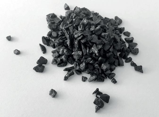
Iron has all the necessary characteristics to act as a good catalyst: it has a high activity, it lasts a long time and it is inexpensive. Small amounts of other components, such as calcium, potassium and aluminium, are added to enhance its activity and improve its durability. This type of catalyst is produced in the form of solid granules.
Figure 6 is a photograph of a commercial example made by Clariant. In contact with these granules under suitable conditions, the synthesis gas mixture of nitrogen and hydrogen reacts to form ammonia.
A very important feature of an iron-based ammonia catalyst is that it only becomes active at temperatures above about 330°C; below that nothing discernible happens. This fact has a direct bearing on the choice of operating conditions in every ammonia synthesis reactor, and that in turn influences the type of reactor used and its materials of construction, as well as the configuration of ancillary plant equipment.
An important consideration concerning the catalyst is that it is susceptible to poisoning by oxygen and compounds contained in it, such as water, carbon monoxide and carbon dioxide, and by other impurities such as sulphur and chlorine. These poisons must be rigorously excluded because if they come into contact with the catalyst it loses its activity, wholly or partially.
Reaction conditions
While the lower limit of the temperature range in which the ammonia synthesis reaction proceeds is set by the initiation temperature of the catalyst (330°C), which is an intrinsic characteristic of the catalyst and thus cannot be varied at will, the upper limit is the temperature at which the reaction mixture reaches chemical equilibrium, and that can be altered, at least to some extent. For, as we have seen from the curves in Figure 5, the equilibrium concentration of ammonia at any particular temperature is enhanced by increasing the pressure.
As already noted, the ammonia reaction is exothermic, which means that the temperature will rise unless cooling is provided. For technical and engineering reasons, the catalyst beds in contemporary ammonia plants are usually adiabatic (uncooled); so, as the reacting gases pass through the catalyst, the temperature of both the gas and the catalyst rises until it reaches an end point close to equilibrium. The theoretical progression of the reaction (that is, how much of the reactant gas is converted into product in its passage through the catalyst) depends on the distance between the starting point and the equilibrium curve (see Figure 7). The greater the distance, the further the reaction will progress. Applying pressure has the effect of moving the equilibrium curve further from the axes, increasing that distance and thus the achievable degree of conversion. Today most plants operate at pressures between 100 and 200 bar.
In Figure 7 the end point is shown slightly short of the equilibrium curve. That is because the further the reaction progresses the slower it gets. The reason is that the rates of both the forward and backward reactions are proportional to the concentration of their participating reactants. As the conversion of nitrogen and hydrogen progresses, their combined concentration falls, so the rate at which they are converted to ammonia decreases. And because the concentration of ammonia increases, the rate at which it decomposes back to the elements rises. At equilibrium the rate of forward reaction exactly balances that of the backward reaction. But, before that, at a certain point the net rate of the forward reaction becomes too slow to be practical.
Configuration of the synthesis reactor
To achieve as closely as possible the required degree of conversion of the reactants into products, as determined by the distance between the initiation temperature and the equilibrium curve, a catalyst bed must contain a sufficient volume of catalyst, which depends on its activity (the capacity of one of a unit volume of catalyst to convert the reactants into product in a unit of time, expressed as kilogrammes
Fig. 7: Reaction profile of a catalyst bed
of product per cubic metre of catalyst per second). Since the upper limit of the conversion is determined by the equilibrium curve, increasing the volume of catalyst beyond that value is pointless, because once the equilibrium curve has been reached, conversion effectively stops, no matter how much catalyst is present. But it is possible to increase the overall conversion attained in the reactor by providing additional catalyst beds and cooling the gas between them. This shifts the gas conditions away from the equilibrium curve, so when exposed to further catalyst in another bed, more nitrogen and hydrogen will combine.
The progression of the gas conditions in a modern three-bed ammonia converter is represented by the broken blue line in Figure 8, starting from the point at the lower left end of the line and finishing at the upper right point. The sloping sections of the line represent the reaction in the various catalyst beds and the horizontal sections the inter-bed cooling.
As in most processes involving equilibrium reactions, the law of diminishing returns applies to the number of catalyst beds that can be used in an ammonia converter. The extent to which the gas can be cooled between the stages is limited because, as the concentration of nitrogen and hydrogen in the gas dwindles, the temper-
MAXIMUM REACTION VELOCIT Y CURVE
EQUILIBRIUM CURVE
Fig. 8: Reaction profile in a three-bed ammonia converter
XNH3
Ammonia concentration
ature needed to attain a reasonable rate of conversion in the successive catalyst bed rises. At the same time, as the equilibrium curve in Figure 8 shows, the higher the concentration of ammonia, the lower will be the equilibrium temperature. The maximum practical number of beds is four, but for reasons of cost it is more usually limited to three.
The cooling between beds is provided by the cool incoming feed gas, which is heated to the required reaction temperature in the process. The most common configuration of a synthesis reactor therefore comprises three catalyst beds with two intermediate heat exchangers, which cool the gas in the output from the first and from the second bed, preheating the cool reactant gas (Figure 9).
With this configuration, at a working pressure of 150 bar, about 30% of the reactant gas can be converted into product, reaching an ammonia concentration of about 20% by volume.
The synthesis loop
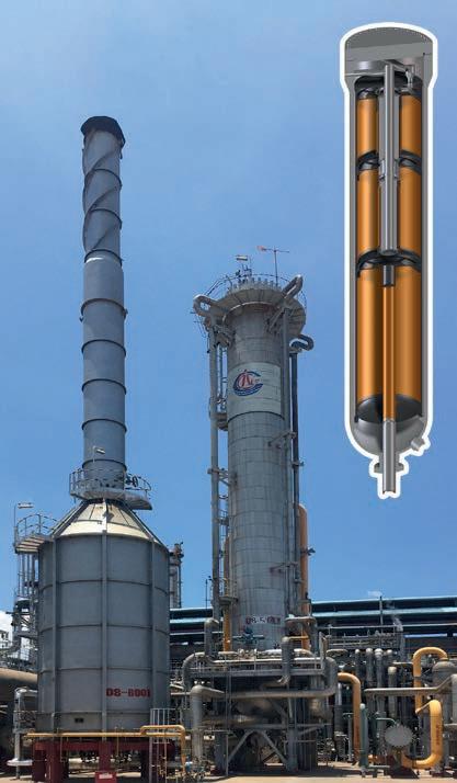
Given that only 30% of reactant gas can be converted into product, and that producing the reactant gas is expensive in terms of both the energy and the complex plant needed, the product has to be separated and the reactant gas recycled to the synthesis reactor to complete its conversion. How the gas is treated after leaving the reactor depends on which of the available methods of separating the ammonia product is chosen. Ammonia is very soluble in water, so one possible method is to scrub the gas leaving the reactor with water and recirculate it to the reactor. But the outgoing scrubbed gas is bound to be saturated with water, and water is a poison for the catalyst. It only takes a moisture concentration of 5 ppmv (parts per million by volume) or more for the catalyst to begin to deactivate. The first ammonia plants
Fig. 9. Synthesis reactor: (Left) Internal design (Right) Unit installed in a 2000 t/d plant
SYNTHESIS REACTOR
BOILER
CHILL RECOVERY EXCHANGER
AMMONIA CONDENSERS
CONDENSATION AND SEPARATION
COOLING WATER RECYCLE GAS
GAS/LIQUID SEPARATOR
STEAM WATER
SYNTHESIS GAS CIRCULATOR
built by BASF used this method, but the life of the catalyst was very short. So recycle gas scrubbed in this way would have to be dried completely. For industrial use the ammonia product must also be pure and has to be separated from the water in which it has been dissolved. This separation is possible but very energy-intensive. For these reasons water scrubbing is not used nowadays.
Fortunately, ammonia can be condensed by chilling the gas mixture to a low temperature. At the pressure at which the synthesis is carried out, it already begins to condense at around 40°C, but to attain almost total condensation it is necessary to reduce the temperature to below 0°C. Industrial plants cool the gases to temperatures ranging from -10°C to -30°C; the condensation temperature chosen depends on many parameters, so different design engineers choose different temperatures. But once the plant has been designed with a certain condensation temperature, this can no longer be changed in any but the slightest degree.
With the synthesis reactor and the ammonia separation method defined thus, the whole ‘synthesis loop’ ‒ the section of the plant where the gas is converted into product and the product is separated from the unconverted reactants ‒ is now almost defined. It entails one more operation: heat recovery.
Fig. 10: Synthesis loop
REFRIGERANT AMMONIA
LIQUID AMMONIA
Ammonia synthesis is an exothermic reaction and the amount of heat produced is considerable, so it is necessary to recover it in the interests of energy-efficiency.
The synthesis loop can therefore be divided into four main sections:
• The reactor, in which the ammonia synthesis occurs
• Recovery of the heat of reaction
• Condensation and separation of the ammonia produced, which also includes the refrigeration cycle needed to cool the gas and condense the ammonia
• Compression of the synthesis gas to the operating pressure of the loop and recompression of the unreacted gas that is to be recycled to the reactor.
Heat recovery
At the exit of the reactor, as stated above, there is a reaction heat recovery section. The gas leaving the reactor is at a very high temperature. The most logical thing to do is to recover this heat by generating steam and heating the water needed to produce it.
The exit temperature from the third catalyst bed is around 420-450°C, which is sufficiently high to produce saturated steam at 100 bar and 310°C. The water to be vaporised is available at about 110°C. So it is possible to provide a chain of heat exchangers downstream of the reactor in which the first generates the steam at 310°C and the second heats the water required for steam generation. The gas output temperature from this heat exchanger is normally about 250°C, because that is the ideal temperature for preheating the reactant gases that come from the compression section, in which fresh make-up gas is raised to the reaction pressure and residual nitrogen and hydrogen remaining after separation of ammonia from the reactor exhaust are recirculated. At the outlet of the compressor these gases are at about 80°C, and to raise them to the initiation temperature in the first bed of the synthesis reactor (about 220°C) they are heated by the reacted gas leaving the heat recovery section in a gas-gas heat exchanger.
Condensation and separation of the product
Downstream of the heat recovery train is the product separation section. Here the reacted gas is cooled to a temperature of about 100°C in the gas-gas exchanger. It is then further cooled to about 40°C with cooling water. At that temperature the product ammonia begins to condense, forming a two-phase gas/liquid mixture.
This mixture is then cooled to the final condensation temperature, for example to
-10°C, by means of a refrigeration cycle in which the refrigerant fluid is ammonia itself. This choice is made because ammonia is an excellent refrigerant, commonly used in industrial refrigeration, and it is, of course, also readily available in the system.
The refrigeration does not, however, bring the gas from 40 to -10°C in a single stage, because that would not be energy-efficient. Normally at least three stages of refrigeration are used.
The first cooling stage will be described further on due to its special nature. The second stage uses refrigerant ammonia at about 0°C and brings the two-phase mixture to a temperature of about 10°C. The third stage lowers its temperature to about -10°C using refrigerant ammonia at about -20°C.
Product separation and storage
At this point the mixture of gas and liquefied ammonia product is fed into a gas/ liquid separator. The liquid ammonia is depressurised and sent to tanks, where it is held in liquid form while waiting to be used. These tanks can be very large, because it must be possible to store products for quite long periods, normally a few weeks, so as not to have to stop the production plant every time the product cannot be sold or used immediately. These tanks are thermally insulated because they are held at -33°C, the temperature value at which ammonia at atmospheric pressure boils. The ammonia which evaporates in the tank because of heat ingress is re-condensed in a dedicated refrigeration cycle.
Recycling of unreacted gases
The gas separated from the liquid contains hydrogen and nitrogen which did not react in the reactor and which must now be re-used. The first step is to recover the chilling potential of the cold gas in the first stage gas/gas heat exchanger of the refrigeration section by using it to cool the incoming reacted gas from the water-cooled exchanger from 40°C to about 30°C. The separated gas leaves the gas/ gas exchanger at about 40°C.
Recompression of the recycle gas
At this point the unreacted gases are now at a lower pressure than at the reactor inlet because of resistance to flow encountered in the reactor and the whole chain of heat exchangers and pipes that connect them. Before they can be returned to the reactor, therefore, their pressure must be topped up in a single compression stage, known as the circulator because it circulates the gas in the synthesis ‘loop’. After
that the recycle gas can be mixed with the fresh gas coming from the synthesis gas preparation section of the plant. The combined gas streams are then sent to the synthesis reactor after being preheated against the reactor effluent, thus closing the loop.
Preparation of the synthesis gas
In most modern cases the synthesis gas, containing the hydrogen and nitrogen, is prepared from three simple components, natural gas, water and air: the hydrogen is obtained from natural gas and water and the nitrogen from the air. The production of hydrogen is the most complex, time consuming and expensive part of the operation.
Natural gas is largely made up of methane, which contains one atom of carbon and four of hydrogen and is represented by the formula CH4. The methane molecule is very stable and it is not easy to separate the hydrogen atoms from the carbon: the reaction that is used for this purpose is called ‘steam reforming’ (equation 2).
CH 4 + H2O ⇌ CO + 3H2 (2)
The methane is made to react with water vapour to produce carbon monoxide and hydrogen.
The carbon monoxide reacts in turn with more water vapour according to the reaction known as ‘shift conversion’ or ‘CO shift’ (equation 3).
CO + H2O ⇋ CO2 + H 2 (3)
Reforming reaction
The reforming reaction, although seemingly simple, is difficult to achieve because, like the ammonia synthesis reaction, it is an equilibrium. It also requires the use of a catalyst, here with a nickel base, but even with the help of the catalyst it will only work at an industrially useful rate at very high temperatures, between 750 and 1000°C. The reason for this very high operating temperature is that the reaction is highly endothermic, absorbing a large amount of heat, and therefore, unlike the ammonia synthesis reaction, it is favoured by high temperatures.
The nickel-based catalyst is especially susceptible to poisoning by sulphur compounds normally present in natural gas. For that reason, the natural gas feed must be subjected to a desulphurisation treatment before being fed to the reformer.
The hydrogen produced in the reforming reaction must then be separated from the
other compounds, i.e. CO and CO2, which ‒ as mentioned ‒ are powerful poisons for the ammonia synthesis catalyst. Because the hydrogen, together with the nitrogen, has to be compressed to the pressure of the synthesis loop (150-200 bar), it is desireable to produce it at the highest pressure possible so as to make savings in compression costs. However, pressure disfavours the reforming reaction, so to compensate it is necessary to run the reformer at the highest possible temperature. For these reasons, the reforming reactor is subject to a number of major technical challenges: very high temperatures, catalyst use, high heat fluxes, and high pressure. To address these requires a special design. It consists of vertical metal tubes containing the catalyst, through which the mixture of methane and steam passes, all the time heated externally by powerful flames obtained by burning methane with air. This assembly is called the reforming furnace (Figure 11), and it is comparable in size to a large building inside which the tubes are arranged in parallel rows. An array of burners on the walls or ceiling of the furnace box, depending on the type of furnace used, provides the heat. The furnace walls are entirely covered by thermally insulating material (refractory cement or insulating fibres) to contain the large quantity of high-temperature heat. The furnace is maintained under a slight vacuum by a fan in the exhaust duct to ensure that the very hot combustion gas, at 1000-1500°C, cannot escape through cracks in the walls or inspection doors, but rather that ambient air enters.
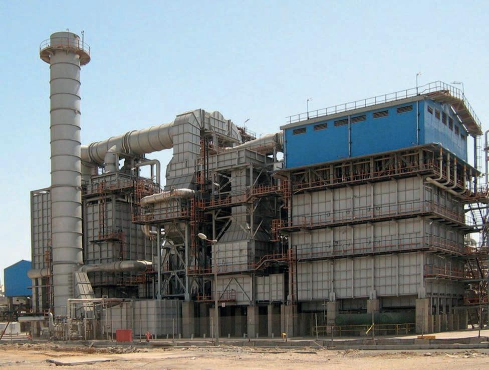
Fig. 11: Reforming furnace in a 2,000-MTD ammonia plant
As emphasised in the foregoing, the reaction is carried out at the highest pressure possible, and its value is determined by the mechanical strength of the pipes containing the catalyst, the walls of which are at a temperature of over 800°C. This pressure is in the range 30-40 bar. The process gas exiting the reformer contains the hydrogen produced, but also a significant amount of methane, around 10% in volume, because of the limitation on conversion dictated by the chemical equilibrium.
At this point, in a second reactor, the nitrogen is introduced in the form of air. The oxygen contained in this air immediately reacts with hydrogen and methane, burning part and raising the temperature of the mixture. The latter is then passed through a bed of nickel-based catalyst, where reforming of the residual methane is virtually completed on account of the very high temperature reached. At the outlet from the catalyst bed the temperature is around 950°C and the methane content has dropped to 0.3-0.4% by volume.
The reforming of methane is thus performed in two stages. The first-stage reforming furnace is known as ‘primary reforming’, and the second, air-fed reactor is called ‘secondary reforming’.
The reformed gas now contains hydrogen and the nitrogen necessary for ammonia production. It is cooled to about 350°C in a waste heat boiler, producing high-pressure steam.
The CO shift reaction (equation 3 above) takes place in both the primary and secondary reforming stages, but to a modest extent. The reason is that it is exothermic (heat-producing) and thus favoured by low temperatures, not by the conditions in the two reformers.
This reaction is, however, very useful because it converts the carbon monoxide into carbon dioxide, which is much easier and safer to remove from the synthesis gas than carbon monoxide, and it produces further hydrogen. So it is completed as closely as possible in the next section of the synthesis gas plant, which comprises two stages using different catalysts.
The first stage is called the high-temperature (HT) shift. The catalyst in this stage, based on iron and chromium, is active between 350°C and 500°C, which allows conversion of most of the carbon monoxide to carbon dioxide and hydrogen. Since, however, the reaction is exothermic and limited by the equilibrium, this reaction step cannot convert all the carbon monoxide; at the outlet from the reactor the gas still has a concentration of about 3% carbon monoxide.
The second reaction stage is the low-temperature (LT) shift, which takes place on a catalyst based on copper and zinc, active between 200°C and 300°C. In this stage the CO conversion is essentially completed: the residual CO content at the outlet is 0.2-0.3%.
Purification of the synthesis gas
The synthesis gas now contains primarily hydrogen, nitrogen, carbon dioxide and water vapour with smaller concentrations of carbon monoxide, methane and argon. Carbon dioxide, carbon monoxide and methane are residues of the reforming and shift reactions, while the argon comes from the air introduced into the secondary reformer. Before being used in the ammonia synthesis section the gas must be purified of CO2, CO and water, which are poisons for the synthesis catalyst.
The carbon dioxide is almost entirely removed by ‘scrubbing’ the gas (contacting it with a liquid which absorbs it). Various liquids can be used for the purpose, usually aqueous solutions containing basic compounds such as potassium carbonate or alkanolamines. When the carbon dioxide, which is an acidic compound, comes into contact with these solutions, it reacts with the basic constituent to form a salt and is thus retained in the solution. The scrubbed gas has very low residual concentrations of CO2, between 100 and 1000 ppmv.
The scrubbing solution must be regenerated to allow it to be reused; in other words, the CO2 it contains must be displaced. That is achieved by depressurising the solution at atmospheric pressure and heating it. The gaseous CO2 released is separated and can be used for other purposes. The scrubbing solution is ‘clean’ and can be reused for washing the synthesis gas.
At this point the preparation of the synthesis gas is almost finished: it is only necessary to remove the residual traces of oxygenated compounds. In the case of CO and CO2, this is done by using the reverse of the reforming reaction, known as methanation, in which these two molecules react with hydrogen, forming methane and water (equations 4 and 5):
DESULPHURIZATION
PRIMARY REFORMING
SECONDARY REFORMING
Fig. 12: Synthesis gas preparation section
Boiler
Boiler
CO + 3H2 ⇋ CH 4 + H2O (4)
CO2 + 4H2 ⇋ CH 4 + 2H2O (5)
It may seem strange that after all the effort made to obtain the hydrogen from the methane it is then consumed to produce methane again, but these reactions are the simplest way to completely eliminate these two molecules and the amounts involved are, of course, small in relation to the whole. In fact the two methanation reactions are strongly favoured at lower temperatures, taking place rapidly at around 250-300°C on a nickel-based catalyst similar, therefore, to that used in the reforming section.
After methanation the only oxygenated compound remaining to be eliminated is water vapour. That can be done in two ways.
• The water vapour is adsorbed on a strongly hydrophilic granular solid such as zeolite, similar to that used for the litter for domestic cats.
• Alternatively, it is absorbed in liquid ammonia. As mentioned above, ammonia is very soluble in water, and the opposite also applies, so by scrubbing the gas with liquid ammonia produced in the synthesis ‘loop’, all the water contained dissolves in the ammonia leaving the gas completely dehydrated.
The purified gas now contains only hydrogen and nitrogen, in the required proportions, and traces of methane and argon, which are inert under the conditions in the ammonia synthesis reactor, so the gas mixture can then be finally compressed to the synthesis pressure. Figure 12 summarises schematically the main operations described.
Depressurization
The synthesis gas is compressed to the loop operating pressure in centrifugal compressors, driven by steam turbines. These machines are complex and expensive because they have a large power requirement (tens of megawatts) and have to rotate at a very high speed (greater than 10,000 revolutions/minute) as a result of the physical properties of hydrogen.
As the above account has shown, synthesis gas preparation is complex because it entails many operations, involving reactions, scrubbing, exchange of large amounts of heat, and compression, all at high pressures, and some at very high temperatures.
As a result, ammonia production plants are, in fact, among the most complex and expensive in the entire chemicals industry.
Integration and energy saving
Besides being very complex and costly, plants for the production of ammonia are also big energy consumers. It is therefore essential to design them to be as efficient as possible. Even after 100 years, the level of efficiency continues to increase thanks to technical advances that are constantly being made in various parts of the plants.
In addition to the efficiency of the various component parts, such as turbines, compressors and chemical reactors, energy integration is of great importance in ammonia plants. For example, the total power consumed by the three main compressors in a modern high-capacity plant is approximately 50 megawatts, equivalent to the domestic electricity consumption of 250,000 people. But it is possible to produce large quantities of steam at high pressure downstream of the secondary reformer, the high-temperature shift section and the ammonia synthesis reactor. Moreover, the combustion gases from the burners which supply heat to the primary reformer tubes leave the furnace box at very high temperatures (around 1,000°C).
By recovering all this heat in the form of steam it is possible to drive all the compressors of the plant with steam turbines, so that the plant does not have to import energy from the outside over and above the natural gas used in the reforming reaction and for firing the furnace. Instead, a modern ammonia plant exports a significant amount of steam, which serves to operate the urea plant that is almost always associated with it.
In practice, though, and in order to ensure smooth, continuous operation, most ammonia plants are set up to import some electricity from the grid, and a certain amount of surplus steam is generated.
This system of using ‘waste’ heat from the production process to provide a plant’s energy needs is a notable example of energy integration.
Production cost of ammonia over time
Thanks to successive improvements in the technologies involved in the design and construction of ammonia plants, it has been possible over the history of the ammonia industry to reduce the specific energy consumption per tonne produced by about 75%, as shown in Figure13.
Stoichiometric requirments (20.0 GJ/t NH3)
NH3 lower heating value (18.6 GJ/t NH3)
Source: Vaclav Smil, “Enriching the Earth, Fritz Haber, Carl Bosch and the Transformation of World Food Production”, p. 47. MIT Press (2001).
So many improvements have been introduced over the decades that it is impossible to list them all. The most important have been the transition from the use of coal as the raw material to natural gas, the introduction of steam reforming, the development of the low-temperature shift, improvements in the CO2 removal section, the replacement of reciprocating compressors by centrifugal ones, the increase in the size of individual plants, energy integration with the use of steam turbines for driving the compressors, improvements to the reactors, with the introduction of
radial-flow reactors first and axial-radial reactors later, better techniques of instrumentation and control, and so on.
This long process of technological progress makes it possible to build systems with progressively higher capacity; today the largest plants produce 3,300 t/d and are so reliable that they can be operated for three or four years without interruption, while their specific energy consumption, as mentioned, is only a quarter that of the first installations.
Patents, licences and know-how
The technological developments that have led, in the course of a century, from the first BASF ammonia plants to those of today, have covered every conceivable technical aspect of ammonia production, from the more visible, such as reactors and compressors, to the less visible ones like catalysts, materials of construction for equipment, pipes, etc., control systems, effluent treatment, emission control, and a innumerable other devices and processes.
These developments are the result of tremendous effort and ingenuity and of very substantial capital investment in research. Understandably, those who come up with novel developments seek to protect their inventions by filing patent applications. In consequence, the patent literature from around the world contains a wealth of documents concerning the production of ammonia or ancillary operations. However, the important patents in this field are in the hands of only a few specialist companies, whose technology is discussed in later chapters of this book. That means that anyone wishing to build an up-to-date ammonia plant, or to modify an existing one to make it more efficient and competitive, is effectively bound to purchase a licence from one of those companies that have committed the human and financial resources to make it possible. The licence gives access to much more than just the technology covered by licensors’ patents: just as important is the knowledge that the licensors have accumulated from their experience in implementing their technology in previous projects. This vital asset, commonly referred to as ‘know-how’, is especially indispensable in an ammonia project, given the critical and complex nature of this type of plant.
There is no question of the vital importance of ammonia production to humanity. It is an undertaking that, in order to o bring about new or expanded capacity, based on ever-evolving technology, entails substantial capital risk. The licensor’s track record, in respect of both the performance of the technology and its implementation in previous projects, is the customer’s best assurance of a successful outcome.

CHAPTER 4 THE BASF PROCESS
Luca Bianchi
Brief history
Badische Anilin und Soda-Fabrik, the company better known as BASF, first developed the process for the production of ammonia by direct synthesis from its elements. The impact of this major technological achievement on the sustainability and growth of the human race in modern times is comparable to that of the invention of agriculture itself about 10,000 years earlier.
The company was founded in 1865 in Mannheim by four partners (Friedrich Engelhorn, Carl Klemm, August Clemm and the banker Seligmann Ladenburg) to manufacture synthetic dyes for the emerging German textile industry, which had developed tremendously during the first half of the nineteenth century. This was a major epoch of the first industrial revolution. It was followed by a second industrial revolution based on applications of chemistry and electricity.
For the company’s headquarters and its main factory, land was acquired in Ludwigshafen, on the opposite bank of the Rhine, which at that time was part of the Kingdom of Bavaria. BASF enjoyed immediate success, confirming the intuition and optimism of its founders, and within a year it already had 300 employees. Chemists were obviously central figures at BASF, as only on the basis of their research could the new synthetic dyes that the market demanded be routinely discovered and processes developed for producing them on a large scale and at a cost that satisfied the consumers, the dyers and textile printers.
BASF grew to such an extent that by 1900 it was undoubtedly the world’s largest and most technologically developed chemical company, with considerable financial resources and a large number of innovative technical staff, engaged in discovery and product development.
Ammonia
Around 1900, the directors of BASF realised that, in spite of its success as a dye manufacturer, and in order to secure the company’s future, the firm needed to diversify in the same way that other key players in the German chemical industry were doing. Bayer, for example, had embarked on medicinal chemistry based on its dye intermediates. The area that BASF chose to concentrate on was the production of combined nitrogen for use in the manufacture of nitrates, which were the basic ingredients for the preparation of the explosives needed to meet the heady ambitions of the German Empire, in addition to serving the needs of the civil engineering industry, and also to provide fertilizers to maintain Germany’s agricultural sector. These nitrogen products were essential should a naval blockade be imposed by a hostile power (such as the United Kingdom). Such a blockade would quickly cut off the supply of imported nitrates on which Germany was almost totally de-
pendent, not only for explosives but also for fertilizers, potentially resulting in starvation among the population and the collapse of the entire German economy. In fact, as noted in Chapter 1, there was at the time widespread concern among most advanced nations, not just Germany, about the ability of their agricultural sectors to provide enough food to sustain their growing and increasingly urban population. Scientific investigations had already made it clear that the only way of materially boosting the productivity of agricultural land was by the massive use of fertilizers, particularly of the nitrogenous type. So, there was a very clear incentive to find a way of producing these substances and break free from the remote, insecure and finite sources of those of natural origin, particularly imported Chilean nitrate.
Nitrogen fixation
Specifically, BASF decided to focus on the fixation of atmospheric nitrogen (the world’s main nitrogen resource, though nitrogen is substantially unreactive, or inert) and conversion into stable chemical compounds, and therefore more useful forms. BASF set up a nitrogen research group and began to use its considerable resources to study the industrial applicability of processes which had recently been developed, in particular the Birkeland-Eyde electric arc process for the production of nitrogen oxides.
In addition, as part of the company’s intention to investigate all possible routes, with great foresight in 1908 BASF acquired the rights to a processes developed by a chemistry professor at the Karlsruhe Technische Hochschule, Fritz Haber. Haber’s main effort involved fixing atmospheric nitrogen by transforming it into ammonia by direct reaction with hydrogen. That process, to which Haber’s young and talented English assistant Robert Le Rossignol had made a vital contribution by designing and making high-pressure apparatus, had built upon previous efforts and studies carried out by the German chemists Ostwald and Nernst, and the French chemist Le Chatelier.
In essence Haber identified the following critical factors for synthesising ammonia with significant yields [6]:
• the need for working at high pressure: Haber chose to operate at 175-200 atmospheres
• the use of a catalyst.
• the need to separate the ammonia produced and recycle the unreacted gases to the reactor.
Haber originally identified osmium as the optimal catalyst [6] [7], thanks to the
fortuitous fact that he was in possession of a small amount as a result of previous research in other areas. But osmium was then, and still is, an extremely rare and very costly metal, the entire worldwide availability of which amounted to only a few kilogrammes, sufficient only to support an annual ammonia production of 750 tonnes of ammonia. That effectively precluded the industrial use of the process. Haber then proposed replacing the osmium catalyst with uranium, slightly less scarce and expensive but still definitely an exotic material. In addition, uranium was very sensitive to water and oxygen. Since the yield was low, just a few per cent, Haber designed an apparatus that continuously recycled the unreacted gas mixture. Despite vexing technical issues, Haber’s invention had, on paper, distinct advantages over the other methods available at the time. All that was needed was to solve the complex problems that stood in the way of its industrial exploitation.
Development of the process
On 2nd July 1909, Haber demonstrated his benchtop apparatus for synthesis of ammonia from its elements before representatives from BASF [6]. He was able to show that it gave consistent amounts of pure ammonia at each pass. Despite uncertainties because of the untried technology, involving catalysts, high temperatures and high pressures, not to mention the low yield, one of the directors of BASF, and the main supporter of the novel method, Heinrich von Brunk, assigned the difficult task of scaling up Haber’s process from the bench scale to the industrial scale to a young German chemist, Carl Bosch. How he managed it in just five years is the stuff of legend.
Blessed with sound chemical knowledge, a passion for engineering problems and uncommon organisational skills, Bosch immediately got to work and soon identified the three crucial issues that would have to be resolved to transform Haber’s simple, metre tall, laboratory apparatus into a large industrial facility capable of supplying ammonia in large quantities. They were [7]:
• to find a reliable, low-cost, and readily available, ammonia synthesis catalyst
• to build a plant capable of withstanding the high pressures and temperatures required by the process
• to produce the synthesis gas in a continuous operation and with the degree of purity required to prevent the ammonia synthesis catalyst from being contaminated.
To accomplish the assigned task in as short a time as possible these three truly formidable problems had to be solved simultaneously. Such was the importance
attached to his quest that Bosch was always able to count upon the full support of the company management; even at critical moments, when the problems seemed to be multiplying, and things went wrong, he was always promptly guaranteed the technical resources he needed.
In his search for the catalyst, Bosch enlisted the co-operation of BASF research chemist Alwin Mittasch, who quickly organised a laboratory capable of performing multiple tests in parallel, thanks to a battery of miniature reactors designed especially for the purpose. In a relatively short time Mittasch identified the best catalyst as a mixture composed of magnetite, alumina and calcium oxide, which, as it is well known, is still used nowadays.
In the space of just two years Mittasch screened 2,500 different catalysts, including complex mixtures of several elements or their compounds, in about 6,500 trials. By 1920, when the research programme officially ended, he calculated that he had performed about 20,000 experiments. [6]
Engineering problems
The real challenge, however, was the second phase: solving the formidable technical and engineering problems involved in the construction of the plant, of a type which had never previously been investigated for industrial use. There was simply no kind
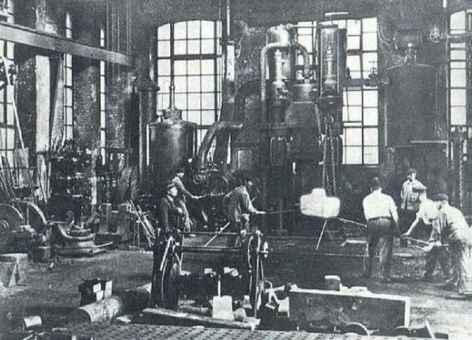
Fig. 14: BASF forge in ‘20s
Source: “The ammonia process”. AICHE/BASF Day, August 27, 2013
of prior experience of working at such high pressures and temperatures. The behaviour of materials under those working conditions were completely unknown. It was also necessary to design and build the large scale equipment, including converters (reactors), compressors, as well as sensors and control devices.
Bosch, with his organisational talent and sustained support from BASF, quickly organised teams to tackle each of the challenges. Remarkably, in a relatively short time they had been addressed and solved. Compressors and pumps, instrumentation, control and safety valves, piping, and related fittings were all devised and designed from scratch. Many components of the plant were built by pioneering methods in workshops specially set up within BASF [8]
Synthesis reactor
The synthesis reactor posed particular problems. From the start, as a result of the brute force conditions, there were frequent explosions. For experimental purposes it became necessary to enclose trial reactors within a solid concrete bunker, which was clearly not acceptable for industrial purposes. Bosch soon identified the cause: a new phenomenon that irreparably impacted on the resistance of all the steels available on the market at that time: a sort of irreversible degradation caused by hydrogen which, because of its small molecular dimensions, is able to permeate virtually any material.
Thanks to an innovation designed by Bosch, the reactor was completely redesigned and made secure. This led BASF to create a metallurgical research group which developed new methods of research and discovered new steel formulations which were more resistant to attack by hydrogen. [6]
Nitrogen
The third challenge was to find a reliable continuous method of preparing synthesis gas in the quantities, and with the degree of purity, required. Nitrogen did not pose difficulties because another German company, Linde, had already been marketing technology for separating air into its components for some time.
Hydrogen
The supply of hydrogen proved to be an even more difficult problem to solve. It was known at the time that pure hydrogen could be obtained easily by electrolysing water, and initial development efforts were in that direction, though they were abandoned because of the high production costs.
Coal, which was abundant in Germany and which had supported the great devel-
opment of all industrial nations, was a better starting material. The process which Bosch and his team ultimately developed for the first test rig included the following unit operations:
• gasification of the coal with steam to form water gas (a mixture of carbon oxides and hydrogen) at high temperature
• scrubbing with water to remove dust and soluble impurities
• filtration through an activated carbon bed to remove traces of sulphur and other catalyst poisons
• scrubbing with a solution of salts of copper and ammonia (cuproammonia solution) to remove all the residual carbon monoxide, which was a powerful poison for the Mittasch catalyst. Adding ammonia to the scrubbing liquor was discovered to be an effective means of preventing the serious problem of corrosion of steels by the scrubbing solution.
By early 1911 BASF had a pilot plant working perfectly in all its parts, capable of producing up to 2 tonnes of ammonia per day.
The experimental phase, involving pilot plants and construction of new equipment, was successfully completed, in a remarkably short time of just three years. It was now time to move from process to plant.
The BASF industrial process
May 7, 1912 marks a very important date in the development of the ammonia process. On that day, just a few months after the end of the experimental phase, BASF began work on erecting a high capacity industrial plant based on what became known as the Haber-Bosch process, at Oppau, not far from Ludwigshafen.
In September 1913, after less than two years of construction work, the new plant began producing synthetic ammonia at the rate of 200 kg/h. The ammonia was converted into ammonium sulphate fertilizer. Nitrogen and hydrogen were made by coal-based processes.
Until the outbreak of the First World War in August 1914, much German public opinion was deeply convinced that any war would be attributable to the ambitions of other Western powers and that Germany needed to prepare for any confrontation only in its self-defence. Moreover, once hostilities began, it was anticipated that the conflict would be short-lived and, therefore, German reserves of ammunition and explosives were more than sufficient. But that turned out not to be the case, as was seen soon after the terrible first battle of the Marne; it was compounded by the
Source: Vaclav Smil, “Enriching the Earth, Fritz Haber, Carl Bosch and the Transformation of World Food Production”. The MIT Press, Cambridge, Massachusetts, London, England, 2001, p. 110.
possible embargo on the importation of Chilean nitrates by the rival forces. At the same time, there were threats to imports of pyrites, and platinum catalyst, essential for producing the sulphuric acid that BASF reacted with ammonia to produce ammonium sulphate. The problem of the shortage of nitrate became especially critical at the end of 1914, following the British naval blockade of Chile. The German shortage of natural resources, apart mainly from coal, made necessary the need to drastically increase the production of ammonia to satisfy ongoing and increasing demands for nitrates to produce the high explosives required for military operations. In 1916, the decision was taken to build a large new synthetic ammonia plant in a more protected location in the heart of Germany. The site chosen was close to the village of Leuna, a few kilometres west of Leipzig. During the war the large complex at Leuna had come close to stopping production due to a lack of raw material (Figure 16). However, during the early 1920s it worked at full capacity dedictated to the production of ammonia according to the new Haber-Bosch process. Leuna would remain the largest synthetic ammonia plant of the interwar period; following successive expansions, its capacity was increased to 250,000 t/a. Though this plant was built far from the French border, and well out of range of bombers in the First World War, its strategic location during the Second World War made it an important target for fierce Allied air bombardments.
Fig. 15 BASF ammonia synthesis process
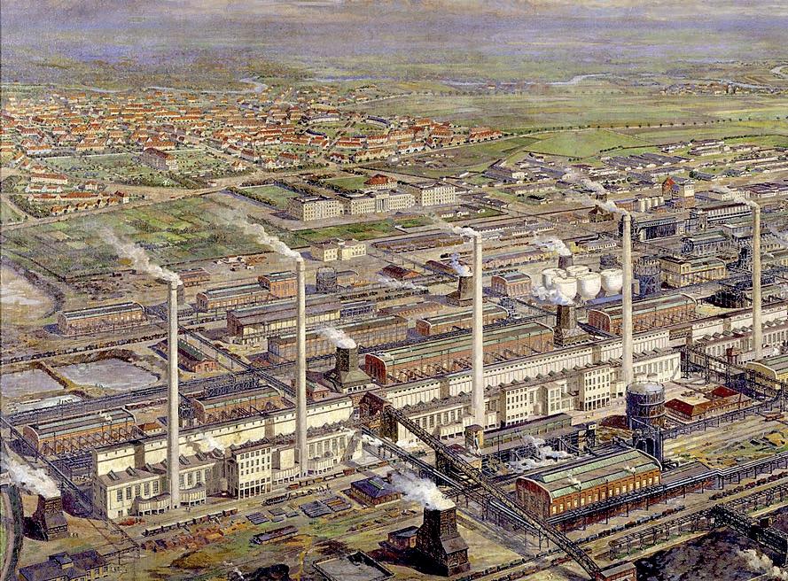
by Columbia University website (http://ci.columbia.edu).
Description of the BASF process
In the following, a description is given of the BASF process as used in the large plant in Leuna.
The plant used both lignite (brown coal) from the Ruhr basin and coke. The former was gasified with air at high temperature in a battery of gasifiers and then stored in a gas holder. This producer gas contained the nitrogen needed in the ammonia synthesis. The coke was treated with high temperature steam in a second battery of gasifiers operating in parallel with the first; the hydrogen-containing gas thus produced was also sent to intermediate storage. Because the reaction absorbs heat, the gasifiers had to be operated intermittently to allow periodic air blowing to reheat the coke. Both gases were then takenfrom the respective gas holders and mixed, before passing through a saturator fed by preheated water.
The mixture of the two gases was treated in a battery of catalytic reactors for the conversion of CO, according to the shift conversion reaction:
Fig. 16
Leuna ammonia plant
Courtesy
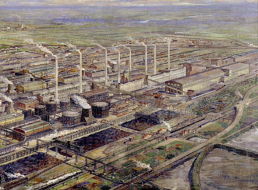
using a catalyst developed by Bosch. The gas mixture was then scrubbed with water at 25 atm in a battery of absorption towers to remove the bulk of the carbon dioxide.
Next the mixture was compressed to 200 atm in a reciprocating compressor and subsequently scrubbed with ammoniacal cuprous formate solution to remove residual carbon monoxide that had remained unconverted after the shift conversion. Further scrubbing with a soda solution removed final traces of carbon dioxide. The mixture of hydrogen and nitrogen, made up in the stoichiometric ratio of 1:3, was treated in a catalytic stage to remove other poisons and finally entered the battery of 19 synthesis reactors. The ammonia generated was absorbed in water at 200 atm, producing a 25% solution of ammonia, and the unreacted gases were recycled to the reactor.
CO + H2O ⇋ CO2 + H 2 (3)
The ammoniacal solution was flashed at intermediate pressure to recover any hydrogen and nitrogen that had been forced into solution under the loop operating pressure. Any ammonia vapour present in the flashed gases was reabsorbed in water before they were recycled.
BASF leaves the scene
The spread of versions of the Haber-Bosch process began immediately after the end of the Great War. This came about because, notwithstanding the Treaty of Versailles, under which Germany was obliged to hand over to the victorious powers its ammonia technology, mainly through patents, the secrets of its working were kept well hidden.
As a manufacturer of chemicals and not an engineering company, BASF throughout the 1920s did not fully appreciate that the spread of its process was now inevitable, and tried to defend its hard-won technological dominance and know-how. It was never willing to license it, despite numerous requests (at least until the mid1930s, and then in Japan). Ironically, if it had done so, the BASF process would probably not have faded out of the picture as quickly as in fact it did. As it was, in response to very strong demand in all developed countries at the time, several inventors, engineers and chemists devised their own alternatives, by-passing the BASF patents, even in the early 1920s. Here it is enough to cite the names of Casale, Claude, Fauser and Uhde, each of whom developed their own process; details of these will be found in the following chapters.
Allied Chemical in the United States in 1921 introduced the first successful home-designed American ammonia plant, installed at Syracuse, New York. In 1924, a second American synthetic ammonia factory, using Casale technology, commenced operations at Niagara Falls. The British in the early 1920s built a large plant at Billingham, drawing in part on industrial espionage involving details of the HaberBosch process. Later in the decade, a plant of 100,000 t/a was built by the French in Toulouse, again using Casale technology, at least for the ammonia synthesis.
The various rival ammonia technologies enjoyed a remarkable degree of commercial success, in terms of production capacities according to the order in which they are given above , to the extent that immediately preceding the Second World War around 90% of the plants in operation were based on them, although in terms of total operating capacity the BASF process was still dominant. Moreover, although the original BASF process, magnificently embodied as it was in the gigantic factories at Oppau and Leuna, had no commercial long-term future in the ammonia synthesis plant market, the principles and the catalyst on which it was based still live on to the
present day in every ammonia plant. This is the precious legacy of the two brilliant main personalities involved, Haber and Bosch, their technicians and the company that supported and pursued their quest with insight and tenacity. It is to that legacy that a major proportion of the present population of the world owes its survival.

CHAPTER 5 THE CASALE STORY
Vittorio Cariati
Casale ammonia technology
Luigi Casale originally developed his ammonia technology in Terni, a town 100 km north-east of Rome with a tradition in iron and steel making going back at least as far as 1641, when an iron works (“La Ferriera”) was set up by special charter from Pope Urban VIII, using locally mined iron ore. Although this operation was interrupted for several decades, including by an earthquake in 1703 and finally destroyed by a flood in 1798, a large modern steel works was established in Terni in 1886, utilising hydro and later hydroelectric power from local rivers. After several changes of ownership, in 1916 “La Ferriera” took the name of “Idros” and produced electricity and, under contract to the Italian navy, hydrogen via electrolysis of water. The conditions in Terni were thus extremely favourable for Casale’s initiative: a metallurgical company, ideal for the production of thick-walled steel equipment, and a hydrogen plant at the same location.
Luigi Casale and his wife Maria Sacchi, also a capable chemist, did not have financial resources of their own but, in 1919, they managed to persuade Idros of Terni to build a pilot synthesis plant for 100 kg/d of ammonia, based on their patent [9]. Figure17 is a process flow diagram.
The hydrogen produced by water electrolysis was stored in a pressurised gas holder. Part of this hydrogen was burned with air, such that the residual nitrogen in the mixture (H2/N2) was in the correct proportion for feeding to the pilot plant.
The catalyst was an element of fundamental importance for the success of the process. The base material was treated iron to which activators had been added. Naturally, the composition and form of the catalyst were continuously improved.
On account of the high operating pressure (800 atm), the plant was capable of producing anhydrous ammonia directly, as it could be condensed by simply cooling the reactor effluent to room temperature. To control the temperature and avoid the risk of overheating the catalyst as a result of the high rate of reaction under the high operating pressure, a small amount of ammonia was recycled with the hydrogen and nitrogen sent to the reaction. Another remarkable innovation that Casale introduced, though at a later date, was the use of an ejector, a static device that replaced the recycle compressor; it simplified the operation considerably but necessitated lowering the operating pressure to 450-500 atm. The design of the adiabatic reactor was also greatly simplified.
Casale obtained patents for his technology from 1921 and devoted himself to licensing it on a global basis. The first step was to establish a company that had sufficient funding resources. Unable to find backing in Italy, he set up Ammonia Casale S.A. (ACSA) in Lugano, with backing from the Basel-based bank E. Gutzwiller & Cie.
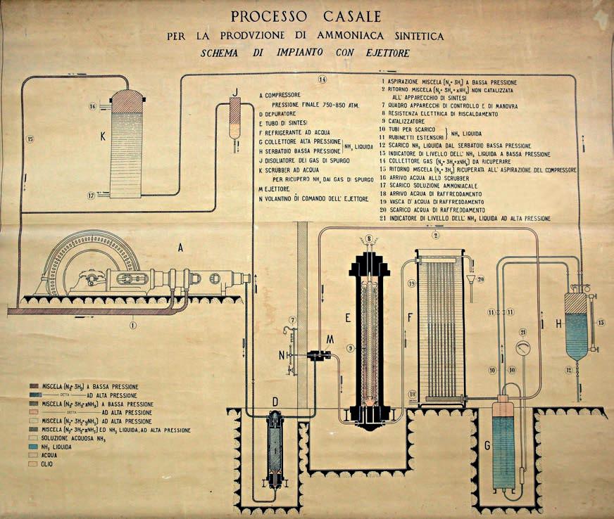
At the time it was not enough to have just the technology: it was also necessary to directly manage the fabrication of the equipment and machinery required for the plant. Equipment for Casale plants was constructed in Terni by local firms which, after several changes of ownership, eventually came together in 1925 as SIRI (Società Italiana Ricerche Industriali) under the ownership of ACSA. From that time, SIRI was the operational arm of ACSA, building the installations as well as producing the hardware using steel produced in the local steel works and formulating the catalyst. The registered office remained in Lugano.
In 1923 the first plant based on Casale technology was opened, in Japan (Figure 18). The second followed in quick succession in Italy, at Nera Montoro, not far from Casale’s works at Terni.
Fig. 17 Original Casale ammonia process
Unlike the BASF process, the Casale process was, at least until the mid-1920s, the only one offered for licensing on the market. It had a considerable technical advantage over the BASF process because it produced directly anhydrous ammonia, whereas the BASF process produced aqueous ammonia. In 1923 Casale technology had already been licensed or adopted for more than 15 plants, in Italy, France, Japan, Switzerland, Spain and the US, with total production capacities of 80,000 tonnes per year (t/a) of ammonia. In 1927, the year of Luigi Casale’s untimely death, world production of ammonia with Casale technology reached 320,000 t/a. In 1930 it reached 1 million t/a, accounting for 60% of world production. The number of ammonia plants built according to what may be called the “first generation” Casale technology reached 200: an unprecedented success for a technology that at the time was rightly considered totally Italian.
Mention should also be made of another brilliant Italian inventor of ammonia technology, Giacomo Fauser, who in the early 1920s set up a partnership with Montecatini at the time the only major chemical company in the country – and built a small pilot plant with a capacity of 4 kg/d of ammonia in Novara. In 1922, after creating “Società Elettrochimica Novarese” (with support from Montecatini), Fauser started up the first plant for the synthesis of ammonia at the “Ammonia e Derivati”
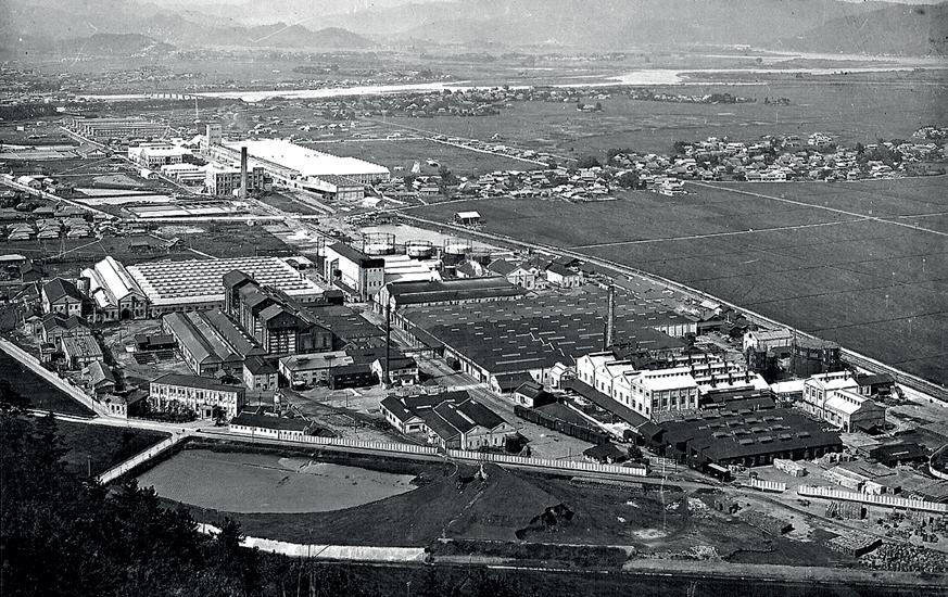
Fig. 18 The first Casale ammonia plant, in Japan
plant in Novara. The initiative was successful and Montecatini thus contributed decisively to the development of Italian agriculture. But Montecatini also followed the policy of BASF and did not licence its process to third parties, at least until the mid1920s, and then on a smaller scale than Casale. Thus Casale had a considerable headstart in licensing his ammonia technology.
Ammonia Casale
The Casale process enjoyed considerable success until the end of the Second World War for clear-cut reasons. Among these were the simplicity of the plant (on account of the use of an injector instead of a compressor for recirculating unreacted synthesis gas) and the anhydrous liquid ammonia product. Also, for many years it was the only process available on the market for third-party operators because it was licensed by an engineering company that was not directly involved in the production and sale of the product [10]
Decline
During the Second World War, SIRI and its production facilities were not heavily damaged. However, at the end of the conflict funds were lacking for research, development and renewal of the plant and its machinery. ACSA was therefore not in a position to keep up with the North American contractors’ breakthrough in integrated plants and the use of oil and gas as raw materials.
With the advent of new technologies working at lower pressures, suitable for larger capacity systems and with the predominance in the 1960s of the American contractor Kellogg, ACSA had lost its competitiveness and for several years was practically out of the market.
Revival
In 1976 Ammonia Casale was sold to the Altech Group, and a new and highly efficient management team promoted what turned out to be a winning marketing strategy focused on the revamping of existing ammonia synthesis plants, regardless of the process originally adopted: the company experienced renewed success.
In 1978 the company was re-financed by Swiss banks and direction of the recovery was assigned to Umberto Zardi, an engineer with long experience in the nitrogen fertilizer industry, previously acquired at Montecatini and Snamprogetti, with extensive assistance from industry experts. Zardi was one of the originators of the Snamprogetti urea process, which is now used worldwide.
The new, totally independent, Ammonia Casale was set up at Via della Posta 4 in Lugano in 1984 with a group of young engineers, joined by specialists from the
field of ammonia and fertilizers. Among them were A. Passariello, catalyst expert, E. Comandini , process engineer, S. De Angelis, mechanical engineer and Bruno Ferzi, purchasing, who had previously worked at SIRI, with the addition of two former specialist colleagues of Umberto Zardi from Montecatini and Snamprogetti, Giorgio Pagani and Gianfranco Bedetti, as well as T. Berriola, an expert in running and commissioning plants. The young engineers, most of whom are now managers at Casale, were Giuseppe Guarino, Ermanno Filippi, Sergio Debernardi, Luca Bianchi, Paolo Silva and Federico Zardi (Figure 20).
As a first step the company developed and finalised the new low pressure drop axial-radial ammonia synthesis reactor. The fact that this reactor design was retrofitted in around 100 plants based on Kellogg and other technologies is proof of its great success [11].
A Winning strategy
On a purely technical level, Casale restarted with the new axial-radial design for the synthesis reactor, first announced at the British Sulphur “Fertilizer Nitrogen” Conference in London in January 1981. This “third generation”reactor was the centrepiece of a number of ammonia plant modernisation projects, and it has since been retrofitted in axial reactors of every type, raising their performance considerably. In spite of its outstanding success, the technological innovation of the axial-radial reactor alone would probably not have led to the rebirth of the company if manage-
Fig. 20. The “Via della Posta” team
ment had not associated with it a new business strategy which ultimately proved to be successful. With American and European giants established in the sector, it would have been difficult, if not impossible, for Casale to acquire contracts for complete new ammonia plants. Therefore, from the 1980s, Casale promoted so-called “in-situ retrofitting” for debottlenecking ammonia plants whose capacity was limited by the synthesis reactor, the majority of which all over the world were at the time of the Kellogg or Chemico axial-flow types, by installing new axial-radial internals inside the existing pressure shell.
For a very modest outlay, this “surgical” operation improved the performance of those reactors to a level that is still comparable today to that of newly built reactors. Fortunately for Casale, there were hundreds of plants that had been operating for many years with low conversions and yields and, above all, with high energy consumption rates, which could certainly benefit enormously from what at Casale was considered a simple change that was nonetheless extremely profitable for the operator. Here was a most obvious solution – a simple yet effective strategy, completely overlooked by competitors – with which Casale addressed the market: “revamping” existing ammonia plants, whatever their original technology, initially only replacing the synthesis reactor internals and catalyst.
Milestones
The first important achievement for the new Casale came in 1984 with the revamp of four Kellogg reactors for CF Industries in the USA. This increased yield by 40%, which gave the operator the choice of significantly reducing specific energy consumption or increasing capacity. What is particularly remarkable about this project is that the contract was obtained on the basis of calculations alone because at the time Casale not only had no prior project as a reference but had not even had an opportunity to test the changes in a pilot plant!
The second milestone came in 1986 as a direct consequence of the first. Following on the incredible success of the CFI project, Casale made a very early entry into the Chinese market at a time when China’s economy was still symbolised by the bicycle.
In the years that followed, Casale quickly cornered the revamp market in the US, China, Russia, India and others, retrofitting 227 ammonia reactors of all types corresponding to more than 40% of the world ammonia production capacity.
Later Casale innovations
Subsequently Casale broadened the scope of its technology development to the synthesis gas production and purification train, enabling it to revamp any section
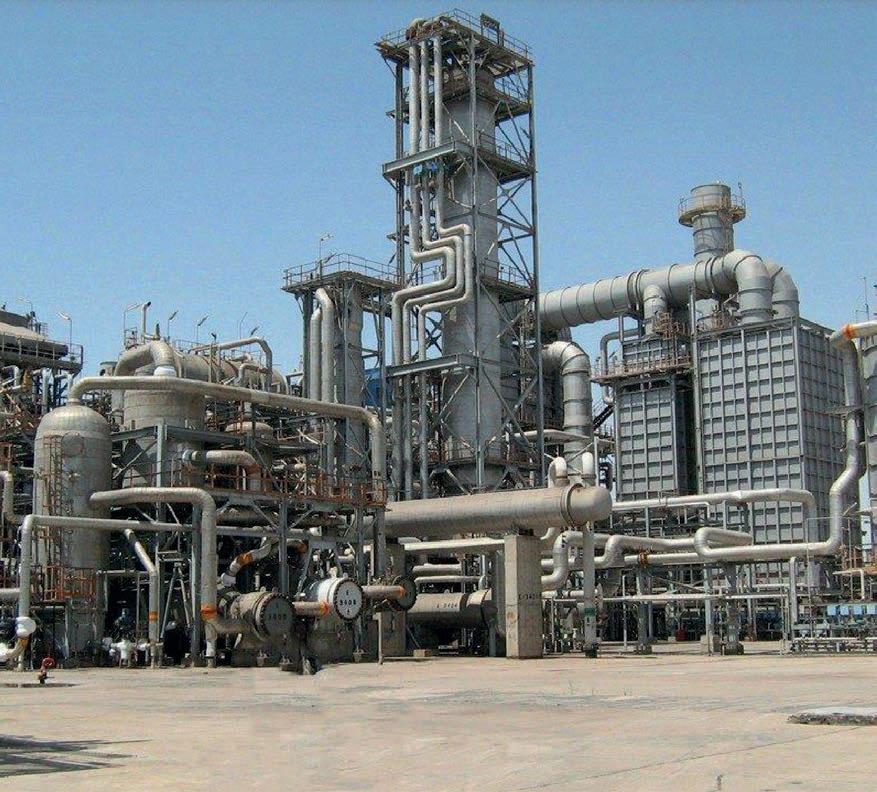
of any ammonia plant. In particular, the axial-radial catalyst bed concept, though developed originally for the ammonia converter, has been widely and very successfully used in shift converters and pre-reformers, which until the 1980s were essentially always axial-flow adiabatic reactors, to reduce pressure loss and improve the utilisation of space within the reactor. These and other home-grown technological advances were then consolidated into integrated concepts for revamping entire plants. These could improve efficiency by up to 20% and increase a plant’s capacity by as much as 100%. From there it was a relatively small step (and a very logical one) for Casale to once again design complete new ammonia plants based almost entirely on its own technology and equipment designs (Figure 21).
Fig. 21: Modern ACSA ammonia plant
In spite of the clear advantages of its axial-radial converter over other adiabatic designs, Casale did not stop there. Theoretically better ammonia yields can be obtained from a synthesis reactor with internally-cooled catalyst beds, such as the tubecooled converters of early ammonia plants, because they operate under near-isothermal conditions at a temperature which provides the best compromise between yield and reaction rate. But such converter designs were not considered practical for the single-stream ammonia plants of 500 t/d or more that became the norm in the 1960s – with one notable exception.
Casale developed a “fourth generation” quasi-isothermal converter design with radially arranged vertical plate heat exchanger elements immersed in the catalyst beds, allowing the axial-radial flow pattern to be retained. This type of converter is equally applicable in revamping and in new plants, guaranteeing the highest efficiency and reliability.
Casale currently offers different process concepts for new ammonia plants, which together cover the whole spectrum of plant capacities, from small to mega, and other requirements.
Other Casale technologies
Throughout its history, and especially since the renaissance of the company in the 1980s, Casale has also focused on other, developing technologies, in later years creating new specialised process companies [11]. Its activities in the area of methanol production began at virtually the same time as in the ammonia field, and, as remarked earlier, from 1930 until after the Second World War the majority of methanol capacity in the world was based on Casale processes.
Casale turned its attention to the area of urea production facilities from 1985, when it began to develop high-efficiency plate reactors and, displaying the same innovative flare as had been the case in the ammonia field, addressed the retrofitting of urea and methanol plants, to the extent that to date it has modernised about 35% of total world urea and methanol facilities.
Encouraged by its favourable experience of diversification into complementary sectors, Casale cast its net wider to encompass downstream products, including melamine (a derivative of urea) and nitric acid, nitrates and compound fertilizers, this time by acquiring well-proven technology from Borealis.
Another important asset is Casale’s acquisition in 2013 of the majority control of Chemoproject Nitrogen in Prague (Czech Republic), which has added to Casale’s staff significant specialized engineering capabilities and whose name was later changed in Casale Project.
Reasons for success
The reasons for the success of Casale over almost a century of activity can be summed up as follows:
• Maximum investment in research for innovative technologies. Currently Casale’s proprietary technologies have exceedingly few significant competitors;
• Accessing cutting-edge complementary third-party technologies and, where available, acquiring them;
• Consolidation of key personnel with many years of experience in the company. Most key personnel have worked with the company for 15-30 years.
• Re-investment in the company by shareholders of most of the profits;
• Maximum customer service, intervening when necessary throughout most of the life of the plants.
Interesting facts
The reactor of the first Casale plant took part in the First World War in its former role as a 400 mm cannon aboard the battleship Dante Alighieri.
Recently hydrogen has been in the headlines as a “clean” fuel for powering internal combustion engines, but we can well imagine the surprise when, on checking the historical records of Casale, it was found that, Casale patented an ammonia-powered car engine in 1935. The same engine was later mounted on a Fiat 527 Ardita 2500 which was offered to government members of that time. The ammonia powered car was unsuccessful, so the researchers at SIRI turned instead to the use of methanol in place of petrol. Given the current anxiety about the environmental effects of automotive fuels derived from petroleum refining, this work almost three quarters of a century ago was far ahead of its time (see chapter 11).
Another interesting fact is that Carlo Emilio Gadda, one of the greats of Italian literature, graduated in electrical engineering from the Milan Politecnico and was an employee of Casale from 1926 to 1931, leaving a prolific, and valuable, archive of technical correspondence with the company.
Conclusion
A good part of the credit for the success of ACSA was due to Mr Gutzwiller, the banker, and his family for initially funding Luigi Casale and then maintaining a constant and keen interest in Casale. No less important, at a later stage, was the far-sightedness of the Swiss banks that decided to support the company during the relaunch in 1980. But the real architects of the recovery were Mr Franco Salimbeni, engineer and entrepreneur, for his decision to take over the firm when it was mired in crisis, and Mr Umberto Zardi, engineer and manager, for having succeeded in finding the right strategy for recovery, a fundamental part of which was a far-sighted policy of reinvesting every franc earned in research and development to nurture ideas generated in house.
Perhaps the most seminal factor in this success story, which absolutely bucks the contemporary trend in corporate culture, is a “handson” philosophy: having “senior” men working side by side with the young engineers who represent the future of the company [10]. Casale is the supreme example of an enterprise founded on the intelligence and tenacity of exceptional men: Luigi Casale, whose creativity and entrepreneurial flair made him eminent as a pioneer in the establishment and development of an industry to which most of humanity today owes its wellbeing; and Umberto Zardi and the talented employees chosen by him, who were responsible for the revival of the company and its present great success.

CHAPTER 6 KELLOGG TECHNOLOGY
Raffaele Ostuni
Introduction
“Since 1943 we have licensed more than 225 ammonia plants, pioneered large-scale, single-train ammonia plants, and have introduced numerous commercially successful ammonia process technologies”.
This is how KBR presented its experience in the ammonia industry in the KBR Technology Overview (source: www.kbr.com, June 9, 2015).
KBR stands for Kellogg Brown & Root, often shortened to Kellogg, a company which has contributed substantially to the advancement of ammonia synthesis technology, developing a new integrated energy process that made possible the construction of hundreds of high-capacity plants in the early 1960s. The Kellogg process, while not a “revolution” as such, was certainly a real “evolution” of the technology as it had been previously known. It enabled a quadrupling of the maximum attainable capacity in a single plant and reduced by half the production cost of syn-
Source: Robert H. Multhaup and Gunther P Eschenbrenner, ‘Technology’s Harvest, Feeding a Growing World Population”. Gulf Publishing Company.
thetic ammonia. It made possible the construction of facilities around the world, particularly in developing countries, a phenomenon known as the “Green Revolution”, which transformed the production of ammonia into a global phenomenon and which has sustained the growth of the world’s population in later decades.
Figure 22 shows the annual world capacity of ammonia plants from 1950 to 1990 and clearly shows its rapid growth after the introduction of the Kellogg process.
Company history
KBR is the result of the merger of two major companies: M. W. Kellogg and Brown & Root.
M.W. Kellogg
Morris W. Kellogg founded his eponymous company in New York back in 1901. In its early years, the company manufactured components such as piping, circular-section appliances and stacks for power generation plants. From the 1920s the company established itself in the nascent petrochemical industry with an innovative oil cracking process. Kellogg formed a research laboratory in 1926 to deepen knowledge of mixtures of hydrocarbons.
Throughout the following decade M. W. Kellogg continued to expand its capabilities in the chemical and petrochemical industries, distinguishing itself particularly via its ability to develop new processes from laboratory scale to industrial scale, as well as its competence in the execution of projects. Of particular importance was the participation of Kellogg in the development of the fluid catalytic cracking (FCC) technology, one of the most important refinery processes. Kellogg designed and built the first FCC unit in 1942, at a refinery in Baton Rouge, Louisiana.
In 1944 Kellogg was taken over by Pullman Inc., of which it was to become a division in 1964. During the Second World War, Kellogg was involved in the American programme to produce an atomic bomb the Manhattan Project proof of the reputation that the company had achieved. Participation in the nuclear programme allowed Kellogg to come into close contact with the best talents in industry and academia, American and otherwise, further increasing its technological capability. After the war, and also stemming from its work on the atomic bomb, Kellogg perfected and made public the important BWR equation of state (from the initials of the engineers who developed it, Benedict-Webb-Rubin), which is still used to describe the behaviour of mixtures of light hydrocarbons. This knowledge forged Kellogg’s strength in cryogenic separation technology, particularly in the field of liquefied natural gas (LNG).
Over the following decade Kellogg aimed decisively at establishing itself as a tech-
nology and contracting company. It expanded its portfolio of oil and gas technologies, and it also dealt with the conversion of coal into liquid hydrocarbons (via Fischer-Tropsch synthesis). It adopted German-derived steam reforming technology, deepening its knowledge through construction and operation of a pilot plant capable of investigating, among other things, the effects of pressures of up to 1,200 psig (more than 80 bar). It perfected the design of a proprietary reforming furnace more efficient than what had hitherto been the state of the art, with increased production capacity of synthesis gas from natural gas. It also put its superiority in the execution of projects to good use thanks to its famous engineering and construction standards. During the 1960s Kellogg focused strongly on the area of ammonia synthesis. In 1970 the company moved its headquarters and research and development laboratory to Houston, Texas, where the headquarters of KBR remains today. In addition to the move, the ‘70s marked a major development for the company and an expansion in international business culminating in the construction of large ammonia plants in Indonesia and Mexico, in addition to large LNG (Liquefied Natural Gas) and LPG (Liquefied Petroleum Gas) plants. Kellogg won major contracts in the Soviet Union of the time and also became the first American contractor to receive contracts from the Republic of China. In 1976, the company changed its name to Pullman Kellogg, and after a series of changes in ownership (and name), in 1988 Kellogg was taken over by Dresser Industries, becoming its main engineering arm. In the 1990s the company remained a strong presence in the LNG market and gained importance in the construction of petrochemical plants.
Brown & Root
Shortly after the end of the First World War, George and Herman Brown began working with Dan Root and set up a construction company in Texas Brown & Root. The company began with the construction of roads, but quickly expanded into other areas, primarily shipbuilding.
After its success in the area of shipbuilding, Brown & Root looked offshore, fast becoming a world leader in the construction of oil platforms. Halliburton, a major oil extraction company, took over Brown & Root in 1962, cementing its reputation. In 1989 Halliburton took over another major engineering company, C. F. Braun Inc., in Alhambra, California, merging it with Brown & Root. C. F. Braun was one of the leading engineering companies in the period after the Second World War, eventually employing more than six thousand staff members, with a turnover of over $100 million in the 1950s. Up to that point, C. F. Braun had built more than 250 chemicals and industrial complexes in the world. The company reflected the personality of its founder and leader, Carl Braun, in his methodical and organised approach to business, and in his highly distinctive corporate culture.
After the war, C. F. Braun focused profitably on the building of chemical and petrochemical plants, including those for ammonia synthesis, in competition with M.W. Kellogg. C. F. Braun developed and marketed a new ammonia synthesis process (US Patent 3,442,613 “Hydrocarbon reforming for production of synthesis gas from which ammonia can be prepared” published May 6, 1969). The Braun process was based on a special cryogenic purification process for syngas, still used by KBR: the Purifier™ process.
KBR
At the end of the ‘90s Halliburton took over Dresser, and merged M.W. Kellogg and Brown & Root to create a new, larger company Kellogg Brown & Root, later simply called KBR. In 2006 KBR reached a new milestone, separating from Halliburton and becoming independent. Today KBR employs approximately 25,000 people in forty countries and is considered one of the leading contractors in the world.
Technology
Kellogg
In the 1960s, Kellogg had focused on the synthesis of ammonia for some years but was struggling to establish itself in the sector over its competitors. No process was distinctive, and each suffered from high investment cost and high energy consumption. All of the competitors offered a similar process which, limited by the technology of that time, allowed a maximum capacity of only 300 short tons per day (st/d). The processes involved steam reforming of natural gas at a pressure of 200 psig (less than 15 bar), a centrifugal air compressor driven by a steam turbine, and an ammonia synthesis section at 4,700 psig (325 bar). It was the compression of the syngas from 200 to 4,700 psig which made the plants uneconomical: in order to produce 300 st/d, three reciprocating compressors driven by gas engines or electric motors were needed. Another downside was the low recovery of waste heat from the process, which made the plants inefficient and very expensive to run. Many technological improvements, however, were made during and after the Second World War, in particular the development of materials suitable for use at high pressures and temperatures. Progress in the aviation field had led to related progress in gas turbines and compressors, as well as improvements in the capabilities of the manufacturers which enabled an increase in equipment size. All the technologies to enable a development like that of Kellogg’s were therefore already available: the achievement of Kellogg was to recognise this; Kellogg decided to change its approach to the design process, adapting it to the equipment and technology available, rather than vice versa. Kellogg also aimed at obtaining a drastic reduction
in energy consumption which would allow production costs to be brought down. The process was developed in just three years between 1962 and 1965, during participation in three tenders for the construction of ammonia plants for Amoco in the USA (a 600 st/d plant), and for ICI in the UK at Severnside and Billingham (600 st/d and 1,000 st/d respectively). In each of the three tenders, the Kellogg engineers carried out numerous studies to improve the various aspects of the process.
In the first tender, for the Amoco plant, for the first time Kellogg proposed use of a centrifugal compressor to perform at least part of the compression of the synthesis gas, up to 2,200 psig. Two reciprocating compressors completed the compression to the synthesis pressure of 4,700 psig. The electrical consumption of the plant was reduced accordingly. The air compressor and refrigeration section were centrifugal, driven by a steam turbine. In this first version, the waste heat of the process was used to generate steam at a pressure of 475 psig, the minimum required for its use in the reformer. The same steam was used to drive turbines.
In the second tender, for ICI at Severnside, Kellogg further perfected the process, completely avoiding the use of reciprocating compressors. This was made possible by the revolutionary decision to operate the ammonia synthesis at only 2,200 psig, half the value previously used, and the maximum pressure allowed with centrifugal compressors. Having avoided reciprocating compressors, all the main machines of the plant could now be driven by steam, with a minimum consumption of electrical energy. The lower synthesis pressure needed much more catalyst and two reactors in parallel. It was Haldor Topsoe which calculated for Kellogg the volume of catalyst required for the low pressure synthesis. Kellogg also improved the heat recovery system compared to the Amoco plant, and increased the pressure of steam generation to 900 psig. However, in spite of the further improvement, the contract was assigned to Bechtel.
But Kellogg persevered. For the third tender (for ICI at Billingham), Kellogg completed the development of the new process with the following additional changes:
• it proposed a single train for the capacity of 1000 st/d, selecting suitable values for reforming pressure (450 psig) and synthesis (confirmed at 2,200 psig);
• this made it possible to compress the syngas in a single centrifugal section with 1,000 st/d capacity, many times higher than the maximum considered achievable a few years earlier;
• it further increased the pressure of the steam generation, bringing it to 1,500 psig, which made it possible to develop greater mechanical power and meet all of the requirements of the equipment in the plant using only the heat recovered from the process;
• steam for the reformer was obtained from a side-stream of the syngas compressor turbine. By this third tender Kellogg had developed a unique synthesis reactor in spite of the low pressure, with a capacity as high as 1000 st/d of ammonia.
The process developed by Kellogg thus contained some innovative concepts whose contribution was twofold: to reduce energy consumption, and therefore the cost of production, and to enable a net increase in the capacity obtainable in a single plant, and therefore a considerable economy of scale.
Figure 23 shows a simplified version of the sequence of the main components of the Kellogg process.
Fig. 23: Simplified Kellogg process for ammonia synthesis [15]
Kellogg obtained a patent for its large-capacity, energy-integrated ammonia process. United States patent US 3,441,393 is a historical document of great interest for those in the industry, and of symbolic importance for the market penetration achieved by the Kellogg process. The inventors of the patent were Finneran, Mayo, Multhaup and Smith. Figure 24 is taken directly from that patent, and shows the flowsheet of the new patented Kellogg process.
Published in US patent 3,441,393 “Process for the production of hydrogen-rich gas”, Assigned to Pullman Inc., 29 April 1969.
It is also worth recognising Kellogg’s achievement in developing all the plant units for this much higher capacity plant, in particular the steam reformer, recovery boilers downstream of the reformer and the heat exchangers, the steam drum and the other components of the steam system. Even more significant is the development of the converter with four beds and the famous “bottle” shape, capable of producing 1000 st/d of ammonia despite the low operating pressure, shown in Figure 25
Fig. 24: Ammonia process flowsheet
Kellogg’s design was immediately recognised as superior to that of its competitors, and this was borne out by its rapid spread. Kellogg must be recognised not only for having developed this new process, but also of having been able to seize a unique opportunity, capitalising to the maximum extent on its advantage over its competitors. Kellogg received orders for seven plants in 1963 (three in the UK, four in the USA) and as many as 20 (eight of which were outside the USA) by 1966, before the first of the new plants was even completed (in 1966).
This, as well as a major breakthrough opportunity, was also a substantial risk for Kellogg; this was truly a new process, never applied before. If there were some design error, this would have been required to be corrected in all twenty plants, with disastrous effects for Kellogg. In addition, any errors in the estimated cost of the plant could have been dangerous if not fatal. On the other hand, waiting for the first plant to come on-stream and assessing the results from it would have allowed Kellogg’s competitors to regain the advantage.
Strategy
Kellogg
It should be acknowledged that Kellogg put into practice a brilliant strategy, which proved to be a winning one, in order to capitalise on the new process. The strategy was based on five rules designed to reduce costs and errors, and to avoid the spread of any problems to the many plants under construction [12]:
• Standardising on two plant sizes – 600 and 1,000 st/d,
• Limiting all major equipment supply to pre-selected vendors,
• Insisting upon design integration with construction requirements,
• Demanding conservative detailed design and maximum checking of engineering and design efforts,
• Quoting for all plants on a lump sum, turnkey basis.
Fig. 25: Kellogg ‘bottle-shaped’ ammonia converter [15]
Of the five rules, the first developing the design exclusively for two plant sizes, 600 and 1,000 st/d was particularly important. Kellogg refused to quote for a 1,500 st/d plant into the mid-1970s, despite pressure from some customers and the resourcefulness of competitors. The commissioning of the first plants confirmed the quality of the process, and further accelerated commercialisation. The figures speak for themselves: from 1965 to 1989, 121 ammonia plants were built and commissioned by Kellogg without any problems.
Braun
Mention should also be made of another ammonia synthesis process, developed only a few years after that of Kellogg: the C. F. Braun process, which became famous for its unit for the cryogenic purification of syngas, the so-called Purifier™. In the cryogenic Purifier™ all of the methane and the excess nitrogen are removed from the synthesis gas, as well as part of the argon. The purified syngas is then practically free of all impurities‚ except for a small amount of argon‚ which reduces the required synthesis pressure and loop purge rate. With the merger of Halliburton and Dresser, this process became part of the KBR portfolio from the mid-1990s. The Braun process did not achieve the same meteoric success as that of Kellogg: only fifteen purifier plants were built in the period 1966-2001, and to date there are about 28 in total. It was, however, significant and the process, still survives almost unchanged today.
Further technological developments
Kellogg (and KBR) have continued to innovate in the field of ammonia in recent years. Of these developments, three deserve special mention: the KAAP™, the KRES™ and TRIG™.
KAAP™ (Kellogg Advanced Ammonia Process) is based on a non-ferrous synthesis catalyst. In the 1980s and ‘90s Kellogg, together with BP, developed a new synthesis catalyst based on ruthenium rather than iron. The process is characterised by a much lower synthesis pressure than the original Kellogg process, at about 1,200 psig. The first plant to use the KAAP™ process was the Ocelot Ammonia Company in Kitimat, British Columbia, in 1994.
KRES™ (Kellogg Reforming Exchanger System) is based on reforming of natural gas in a tube bundle heat exchanger, where the tubes are filled with reforming catalyst. The heat exchanger has a special mechanical design with a single tube plate and can replace the primary reformer.
TRIG™ (Transport Integrated Gasifier) is a fluidised bed coal gasifier based on KBR technology for fluid catalytic cracking. It was developed by KBR for the generation
of power and production of chemicals. TRIG™ is suitable for gasifying coal of various types and is particularly suitable for low rank coals.
Today
KBR is a key player in the synthesis of ammonia, operating as “lead contractor” and supplying all relevant services. It has technologies in almost all plant areas, starting from either gas or coal, with the sole exception of acid gas separation, and including a gasifier, the TRIG™.
KBR offers the following proprietary equipment and processes for ammonia (from www.kbr.com/technologies/ammonia site, visited June 9, 2015):
• 101-C Secondary Reformer Waste Heat Boiler
• 102-C HP Steam Superheater
• 120-C Ammonia Unitized Chiller
• 105-D Ammonia Converter
• 137-L Purifier (Cold Box and Expander/Generator)
• 100-C KRES
• 103-C/ 123-C High Pressure Exchangers
• 103-D Secondary Reformer
• Transport Integrated Gasification (TRIG™).
The ammonia processes offered by KBR include:
• The PURIFIERplus™ ammonia process this combines the proven and reliable technologies of the Purifier™, KBR Reforming Exchanger System (KRES™) and Horizontal Ammonia Synthesis Converter to produce a synergistic, lower-cost process that eliminates the need for an air separation plant and a primary reformer.
• Conventional ammonia process technology. KBR top-fired primary reforming technology is combined with ammonia synthesis in a horizontal ammonia converter over a promoted iron magnetite catalyst at pressures of 140 to 170 bar.
Despite the fact KBR has carried out more than 40 fertilizer plant projects, which in addition to ammonia have also included its derivatives urea, nitric acid, ammonium nitrate, UAN solutions, NPK, triple superphosphate, single superphosphate, di-ammonium phosphate, sulfuric acid, and ammonium sulphate, it has never developed proprietary technologies or a process for production of ammonia by-products.
Strengths
The secrets of KBR’s success, and in particular Kellogg’s success, were as follows:
• The ability to develop innovative solutions and bring them from an idea to a commercial reality.
• The ability to recognise the risks associated with the development of a new idea.
• An insistence on using innovative approaches, both technical and commercial, to business. “Show me something new” was the motto of the founder, Morris Kellogg.
• Long-serving staff, extremely well trained and at ease in the workplace.
• Participation by and support for management in technical and commercial decisions.
• Developments which played to the major strengths of staff.
Key figures
The story of a company like KBR has been marked by many key people who created it and have influenced its destiny. One example is Morris Kellogg, the founder of MW Kellogg, an indomitable innovator with an innate ability to recognise good ideas and turn them into successful business propositions, and who helped create in Kellogg a stimulating atmosphere for ongoing innovation.
But the main importance of Kellogg for the ammonia industry is the high capacity integrated energy process. We must therefore also celebrate the team that developed the process, with the words of Warren Smith, then president of M. W. Kellogg, at the ceremony for the Kirkpatrick Award in 1967:
“in receiving the award, Warren L. Smith, president of the M. W. Kellogg Company, introduced 12 people from his engineering and research groups who played major roles in the development: Len Axelrod, Jack Dwyer, Gunther Eschenbrenner, Jim Finneran, Benn Jesser, Hays Mayo, Bob Multhaup, Fritz Peterson, Lanny Quartulli, Herman Rickerman, Ron Smith and Joe Yarze. “But,” said Smith, “the effort went far beyond these 12. It extended through Kellogg’s chemical engineering, design engineering, catalyst development, and pilot plant groups. [...] In short, the nucleus of the development is in these 12 people, but ringed around them are the Kellogg suppliers, subcontractors and client groups who all played a role in the success of the development”.
References
Eighty percent of Kellogg ammonia plants which began operation during the 1970s and 80s were located in 23 different countries outside traditional ammonia-producing countries such as the United States, Canada, Australia, Japan and Western Europe. In particular, hundreds of large Kellogg ammonia plants were sited where natural gas was present. Of great importance for Kellogg was the ability to penetrate the “Iron Curtain”, building seventeen plants in the Soviet Union, the first in Nevynnomyssk in 1973. Kellogg also succeeded in its attempt to get through the ‘bamboo fence’, building as many as eight plants in China.
The competition, however, was not far behind. Kellogg filed patent US 3,441,393 in the name of Finneran et al. in 1966 (after having already commissioned the first plant!) and kept a certain advantage over its competitors for the first decade. From 1971 to 1982, the share of new ammonia licences was 40% for Kellogg, 20% for ICI, and 8% for Topsoe. After that, however, Kellogg’s market share dropped to less than 30%.

CHAPTER 7 TOPSOE TECHNOLOGY
Francesco Baratto
The company’s origins
Haldor Topsoe A/S, a Danish company founded in 1940 by Dr. Haldor Topsøe, is currently active in the basic chemicals market with a broad portfolio of technologies and catalysts. Today the company has more than 2,200 employees worldwide, of whom 1,700 work in Denmark; the central offices are in Lyngby, a suburb in the north of Copenhagen. The production sites for catalysts, one of the major businesses of the company, are in Frederikssund, Denmark, and Houston, Texas, US. The company also has offices and subsidiaries around the world: Bahrain, Indonesia, China, India, Malaysia, Russia, South America, Germany, Canada, and the United States.
Haldor Topsøe decided to set up his own company in 1940, immediately after the German invasion of Denmark, when the Second World War forced him to leave his job at the Aarhus Edible Oil Refinery, and hospitalisation of his two children with pneumonia prevented the move to the United States.
As he himself declared in an interview in 2010 for the Annual Review of Chemical and Biomolecular Engineering [13], the company’s focus has always been to create new knowledge, also through basic research, and transform it into something with business potential. Obviously, the research carried out is always an area where potential use in industry is already expected, in particular in catalysis. The company’s website states that “knowledge is the basis of development.”
Innovations
The catalysts
Focusing the business of the new company on catalysts was the idea of Haldor Topsøe himself, in spite of the concerns of his first co-workers [14]. The fact that the idea was a winning one is now clear, and one of the mottoes of the company is still “committed to catalyst” (source: www.topsoe.com).
In 1944 Topsøe produced the first batch of catalysts for the production of sulphuric acid, the company’s first major area of business. Another major step was the development in 1948 of the first nickel-based catalyst. In the same year Topsøe began cooperation with Vargöns AB in Vargön, Sweden to produce ammonia synthesis catalyst, which was later to become one of the company’s main business areas. An important name in the development of this catalyst was that of Dr. Anders Nielsen.
Computers
The impetus for the development of this market came about ten years later in 1959, when Topsøe bought one of the first computers (called GIER) for the company and assigned Dr. Jørgen Kjær to supervise the calculation group. Dr. Kjær, who had
already dealt with computer models in his doctoral thesis, was probably the first in the world to describe, via a computer program, what happens in a catalytic reactor. These first computers were used in this way to calculate the optimal conditions for the synthesis of ammonia and its conversion inside the reactor.
Steam reforming furnace
In addition to the ammonia synthesis catalyst and all the other catalysts used in an ammonia plant (desulphurisation, reforming, high and low temperature shift and methanation), the Topsoe technology for the ammonia process is linked to two basic pieces of equipment: the reforming furnace and the ammonia synthesis reactor. The development of the steam reforming furnace, used to convert natural gas and other hydrocarbons into synthesis gas in ammonia, methanol, hydrogen processes and other important petrochemical products, is linked to the name of Dr. Jens Rostrup-Nielsen. The first Topsøe steam reforming furnace was commissioned in 1957 and it took ten years of development, tests and pilot plant experience to achieve this result. The task of perfecting it still continues, particularly from the point of view of the catalyst, where work continues to reduce carbon deposition and load losses.
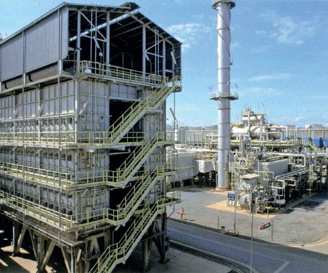
Fig. 26: Topsoe reforming furnace
Source: Courtesy Haldor Topsoe
The Topsoe design of reforming furnaces (Figure 26) is characterised by a number of catalytic tubes in a single row in one or two combustion chambers, with the burners positioned on the walls at different elevations (a so-called “side-fired” design). The flame of the burners is directed backwards, against the refractory muffle, to eliminate the risk of direct impingement on the tubes. The arrangement of the burners allows modulation of the temperature profile along the entire length of the catalytic tube, optimising it to the fullest. To date Haldor Topsoe has designed more than 250 reforming furnaces worldwide (source: www.topsoe.com).
Radial reactor
Topsoe also developed the first radial flow reactor for ammonia synthesis, essential for the construction of large modern plants. Dr. Jens Rostrup-Nielsen liked to compare the axial flow ammonia reactor normally used those days to a cigar which
PRESSURE SHELL
BASKET COVER
COVER PLATE
1ST CATALYST BED
BASKET COVER
INTERBED HEAT EXCHANGER
CENTRE SCREEN
CATALYST SUPPORT
COVER PLATE
OUTER ANNULUS
OUTER BASKET SHELL
BASKET INSULATION
OUTER BASKET SHELL
CATALYST SUPPORT
2ND CATALYST BED
CATALYST SUPPORT
COLD BY-PASS PIPE
MAIN GAS INLET
GAS OUTLET
Source: “Advances in Ammonia Converter Design & Catalyst Loading”, Nitrogen+Syngas Conference, Geneva, Switzerland, 1997.
MAIN GAS INLET COLD BY-PASS INLET
Fig. 27: Topsoe S-200 reactor
is too compressed and therefore difficult to light: the secret is to make holes in the side in order to make the air flow in radially. This is the concept of the radial reactor, which allows low load losses even with very small catalyst sizes, making it more active. This development was made possible by Dr. Jørgen Kjær’s previously mentioned calculation programs, which allowed calculations of this type of reactor, difficult to test on a laboratory scale. In this way the new reactor was actually introduced to the market directly on an industrial scale.
The initial, S-100 reactor was made up of two radial beds with intermediate direct quench, and later perfected with the S-200 model, with two beds with intermediate heat exchanger, and finally the latest version used today, the S-300 (Figure 27), with three catalyst beds with two intermediate exchangers. The first single 1000 st/d loop using a Topsoe radial reactor was commissioned in 1966 by Agrico in Blytheville, USA (www.topsoe.com).
Operating conditions
A Natural gas-based ammonia plant (Figure 28) involves operating the reformer furnace with a steam/carbon ratio of, typically, 2.8 : 1 and an outlet temperature of about 780°C. The carbon monoxide shift section comprises a high temperature shift converter with an iron-based catalyst and a low temperature shift converter with a copper-based catalyst. The subsequent decarbonation section used is the BASF OASE process , the Benfield from UOP or the Giammarco Vetrocoke process. The working pressure of the synthesis loop depends on the plant size but it is usually around 190 bar. The synthesis reactor is of proprietary design, normally with three beds and can be followed by a single-bed reactor (S-50), if a higher conversion per pass is desired. The declared consumption for a facility of this design is 28.5 GJ/MT of ammonia
Patents
Topsoe has always been very careful to protect its know-how through patent protection, covering technologies, catalysts, and processes. The company’s first patent in the field of ammonia goes back to 1960 (DK 98426) and covers catalyst for synthesis and its production methods. The first patent on steam reforming was filed in 1962 (DK 118184) and also concerns the catalyst. The first patent for the ammonia synthesis reactor was filed in 1963 (DK 106275) and claims the benefits of the radial configuration with more than one catalyst bed and intermediate exchangers. At present more than 70 patents have been filed on behalf of Haldor Topsoe with the generic topic of “ammonia”, of which about 10 cover catalysis and the remainder the process itself.
a) Desulfurisation b) Primary Reformer c) Secondary Reformer d) Shift e) Decarbonation
f) Methanation g) Synthesis Compressor
h) Pump i) Heat Recovery j) Synthesis Reactor
Source: “Ullmann’s Encyclopedia of Industrial Chemistry”, Wiley-VCH, Wenheim, Germany, 2002 Sixth Edition.
The 1972 crisis
A very important and dramatic event in the history of Topsoe, which nevertheless eventually had a positive effect on its ammonia business, was the crisis the company went through in 1972 and its subsequent merger with Snamprogetti. It was a sudden crisis, due in part to the fall in profits of the company’s silicon plant in Frederikssund and of its electronics subsidiary Univel, and in part due to international events such as Colonel Gaddafi taking power in Libya, invalidating agreements with the previous government, as well as problems with payments for certain projects in Kuwait. The banks did not help Haldor Topsøe, who came close to having to sell the catalyst business to W.R. Grace or AkzoNobel, who were both very interested in the deal. The arrival of Snamprogetti turned the situation around, allowing the company to remain a unified whole even though 49% of it was now in the hands of the Italians, who could appoint the CEO and CFO. Haldor Topsøe retained 49% of his company and the role of president, and the remaining 2% was earmarked for Snamprogetti as and when Haldor-Topsøe left the company.
Fig. 28: TheTopsoe ammonia process. natural gas
Product ammonia
Relations between the Danes and Italians were not always idyllic, especially as regards long-term strategy [14], but the Topsøe-Snamprogetti union, as an ammonia licensee and EPC contractor on the one hand and a licensee of urea on the other, built a considerable number of fertilizer plants, especially in the Indian subcontinent. In 2007, through a considerable financial effort, Haldor Topsøe was finally able to buy back all the company’s shares and become the sole owner again.
The markets
Of fundamental importance for the development of Haldor Topsoe A/S’s ammonia business was the Indian subcontinent. Topsoe made a major contribution to what was later to be called the “Green Revolution”, which led to a huge increase in Indian agricultural production. Haldor Topsoe had already been active in India and Pakistan through the sale of catalysts., but when, at the end of the 1970s, the Indian government decided to build a pipeline from the gas field near Bombay across the country, and a series of fertilizer plants along the way, Topsoe was one of the first companies to realise the possibilities and to exploit them. To date no less than 80% of the ammonia plants in India have been based upon Topsoe technology, [17].
Other important markets for Topsoe were China, where it has operated since the 1960s selling both catalysts and various technologies, Russia and Brazil, or in other words, all of the so-called “BRIC” countries. Haldor Topsoe has always been alive to the potential of developing countries and has often succeeded in being the first presence in these growing economies.
At present there are 120 plants worldwide based on Haldor Topsoe technology, including 82 fed by natural gas and 38 with other types of feedstock (coal, naphtha, coke oven gas, etc.). The largest proportion, more than 70%, are in Asia, while Europe and the Americas represent about 10% and 15% respectively.
Plants built more recently and with higher capacities include those for QAFCO in Qatar (two lines each with a production of 2,300 t/d), in operation since 2013; Profertil SA at Bahia Blanca in Argentina (2,050 t/d), in operation since 2001; and the OMIFCO plants at Sur in Oman (2 x 1,750 t/d), operating since 2005.
The strengths
Haldor Topsoe A/S has several strengths that allow it to be one of the ammonia market’s leaders. First of all, a reliable technology with many references allowing it to be at the cutting edge for both new plants and the revamping of existing plants. The Topsoe technology is supported by strong and structured research, yet also highly integrated within the company’s other operations. The catalyst business also
constitutes both an economic asset and a way of remaining in touch with customers. Haldor Topsoe catalysts are used in 50% of the world’s production of fertilizers [18]
The strength of Haldor Topsoe A/S is guaranteed by two other important factors: a very broad technology portfolio, which ranges from process chemistry (ammonia, methanol, hydrogen, formaldehyde, Di methy Ether, Synthetic Natural Gas (SNG), sulphuric acid) to refineries (diesel, naphtha, kerosene, VGO), control of emissions (NOx, Volatile Organic Compounds (VOC), sulphur recovery), biofuels and fuel cells, and which ensures strong diversification and market balance. Finally, when Dr. Haldor Topsøe bought back all the shares in the company in 2007, he wanted to strengthen the family’s share of ownership of the company. This ensured the company’s ability to make long-term plans and not look solely to immediate opportunities. For the future, Haldor Topsoe A/S definitely aims to strengthen its position in three core businesses: chemicals, refineries and the environment. Dr. Topsøe was convinced that the technologies and catalyst developments undertaken by the company would make the world a better place to live. Finally, a new strategy is one of increasing participation in projects, becoming co-owner of the plants.

CHAPTER 8 UHDE TECHNOLOGY
Sergio Panza
Uhde GmbH, today’s ThyssenKrupp Industrial Solutions AG (TKIS), is one of the most important engineering companies still active in the ammonia field. It was established by Friedrich Uhde on April 6 1921 (The Uhde story, Journal for the 75th anniversary of Uhde GmbH. Public relation department, 1996) at Bövinghausen (Zur Lebensgeschichte des Begründers des gleichnamigen Weltunternehmens. In: Einbecker Jahrbuch. 49, 2004, S. 115–146) with the purpose of manufacturing pigments for the printing trade, but very soon Uhde began working on producing ammonia using a different process from Haber-Bosch (Angewandte Chemie, Band 78, Seite 346, Verlag Chemie, 1966).
Swedish chemist J.W. Cederberg had been working on developing a catalyst for ammonia synthesis, and this had interested the Gewerkschaft der Steinkohlenzeche Mont Cenis, a German colliery located at Herne-Sodingen (Chemiker-Zeitung/ Chemische Apparatur, Band 90, A. Hüthig, 1966). In 1921 the company began to collaborate with Friedrich Uhde on the development of an ammonia process using this catalyst, and this came to fruition in 1925-1926 when a pilot plant was completed at Mont Cenis.
Uhde’s ambition was to develop a process that would not infringe BASF’s patents (from 1925 owned by I.G. Farben), and the work developed by Cederberg for Mont Cenis proved to be the solution. Cederberg had developed a catalyst based on iron cyanides. Once reduced to iron, this was capable of catalyzing ammonia synthesis at a temperature of 400ºC and a lower operating pressure of 100-120 bar. The main problem of the catalyst was its instability above 450ºC. Two years after the pilot plant began operation, an industrial plant started production at the same site with a capacity of 100 t/d. It had four reactors, each with a capacity of 25 t/d, operating at a pressure of 100 bar. This plant (Figure29) was one of the first to have internal heat exchangers in the ammonia converter and two stages of refrigeration units; these efficient design principles were not exploited in other plants until the 1970s.
Mont Cenisand others establishedthe Gasverarbeitungsgesellschaft (GAVEG) around 1926 to license the technology to other companies, while Uhde engineered and constructed the plants. Up to 1937, 28 ammonia plants were built around the world using to this process.
Source: Vaclav Smil, “Enriching the Earth, Fritz Haber, Carl Bosch and the Transformation of World Food Production”. MIT Press, Cambridge, Massachusetts, 2001).
Mont Cenis was acquired by I.G. Farbenindustrie and this ended various pending suits for patent infringement. Friedrich Uhde then established the Hochdruck-Apparatebau GmbH (Uhde High Pressure Technologies GmbH). In 1929 the company moved to a new headquarters in Dortmund, while a laboratory remained in Bövinghausen for the development of the coal gasification process. Research and development work on the process drained the company’s revenues. and the situation worsened when the Second World War broke out. In 1945, the construction and administration building in Dortmund was destroyed by bombs and occupied by American troops. However, after the war the company’s fortunes changed for the better. In 1950, it received its first large order for a complete nitrogen fertilizer plant at Oulu, Finland, and in 1953 Uhde gained a presence in the USA with the foundation of the Uhde Corporation of America in New York. Outside of the fertilizer field, Uhde started to cooperate with Hoechst, gaining process know how in the fields of organic chemicals, plastics and synthetic fiber production. The new Uhde “Hoechst Branch” was established at Offenbach near Frankfurt am Main.
In 1962 Uhde built the highest-altitude fertilizer plant close to the ancient Inca city of Cuzco in Peru; the altitude of the plant was at an impressive 3,420 m. The project was developed by a consortium between Uhde and Ferrostal, and included a calcium ammonium nitrate plant with a capacity of 149 t/d at a nitrogen content of 26%. The hydrogen required by the ammonia synthesis was obtained through water electrolysis, and this took 75% of the overall plant’s energy requirement, estimated at 24,149 kW.
Fig. 29 Mont Cenis-Uhde ammonia synthesis process.
It is also worth mentioning that Uhde was one of the first engineering companies to adopt computer aided design (CAD), in 1978. In the same year Uhde India Ltd was founded in Mumbai, followed in 1981 by the foundation of Uhde (Pty.), Johannesburg, South Africa and in 1992 by the foundation of OAO Uhde in Dzerzhinsk, Russia.
In 1997 Uhde was merged with Krupp Koppers in the plant construction division of the Krupp Group to form Krupp Uhde GmbH, although the company’s headquarters remained in Dortmund. The main technologies licensed were coking plants and equipment for gas treatment plants; other technologies included the Morphylane process for obtaining high-purity aromatics, as well as coal gasification processes for the production of fuel or synthesis gas.
In 1999 the Krupp Group merged with the Thyssen Group to form ThyssenKrupp AG. Krupp Uhde divested its coking activities as part of the reorientation of the plant construction segments of the two groups, and in 2011 Uhde became ThyssenKrupp Uhde, until more recently it was finally renamed ThyssenKrupp Industrial Solutions (TKIS).
In 2006 the company brought on stream the world’s biggest ammonia plant, with a capacity of 3,300 t/d for the Saudi Arabian Fertilizer Co (SAFCO), located in Al-Jubail, Saudi Arabia, and in 2007 Egyptian Agrium Nitrogen Products Co. awarded Uhde its biggest contract in the company’s 80 year history to build a fertilizer complex at Damietta in Egypt.
Innovations
Top-fired furnace
In 1967 Uhde developed a top-fired furnace for syngas generation using catalytic high-temperature cracking of hydrocarbons with steam. This furnace was equipped with a brick-lined “cold” gas header system.
Turbo compressors
In 1968 Uhde made a breakthrough with the construction of a heat integrated ammonia plant built with a turbo-compressor. The plant, built for Gewerkschaft Victor at Castrop-Rauxel, Germany, was based on a single train arrangement, and had a capacity of 880 t/d.
Radial flow reactor
In 1982 Uhde introduced another important improvement to its ammonia technology by the introduction of a new Uhde ammonia reactor with radial flow and
indirect heat exchange. The first Uhde grass roots ammonia plant with a capacity of 2,000 t/d was built in 1990 in Belle Plaine, Saskatchewan, Canada for Saskferco Inc.
Patents
Numerous patents have been registered by Uhde, some of them of great significance for the company’s history such as US 2052326 A (Figure30), which describes a tube gas cooled ammonia converter where the heat exchanging tubes are immersed in the catalytic bed; the cooling medium for this pseudo-isothermal converter is the synthesis gas itself.
Aug 25, 1936
US Patent 2052326A, August 1936.
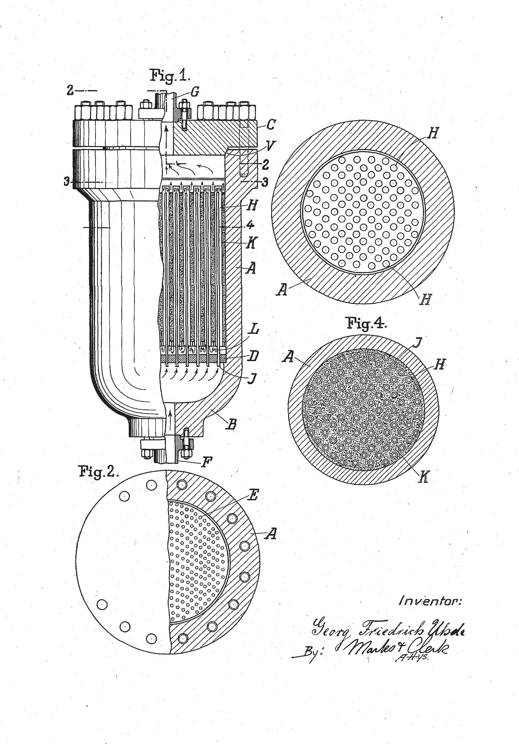
Filed Sept 30 1926 2 Sheets-Sheet l
Fig. 30: Tube cooled ammonia converter
Fig 3
It is also worth mentioning a more recent patent (EP 1339641B1) related to the so called ‘dual pressure process’: this patent is the basis for the largest ammonia plant currently operated in the world.
Primary reformer
Of the proprietary technologies supplied by Uhde (source: www.thyssenkrupp-industrial-solutions.com) for ammonia plants, the primary reformer comes first in the process flow scheme. Uhde’s primary reformer is top-fired with low NOx forced draft burners; these burners are lodged in the furnace ceiling between the tube rows and between the outer tube row and the side walls. In the reformer bottom, tunnel burners are provided for gas reheating.
Uhde reformers use centrifugally-cast high alloy steel catalytic tubes, with high creep rupture strength; this permits the use of large catalytic tubes which, thanks to the improved material, can withstand the severe reformer operating conditions, and allows the reduction of catalytic tubes installed in the furnace; the final outcome is a smaller dimension for the primary reformer.
Another feature of the Uhde primary reformer design is the cold outlet manifold system. In a standard design the hot process outlet line from the reformer undergoes significant thermal expansion which could cause stress issues; to overcome this risk Uhde installs expansion bellows to allow thermal expansion of the outlet manifold. These bellows prevent any ingress of air into the heated zone of the furnace, preserving the temperature of the flue gas flowing through the downstream coils (Figure 31).
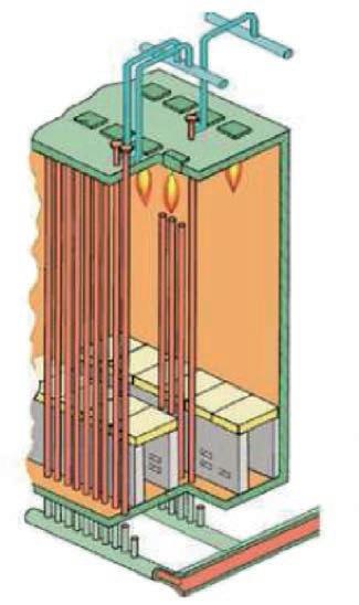
Fig. 31: Primary reformer
(Source: Leading fertilizer technologies – Ammonia, ThyssenKrupp Industrial Solutions AG).
Burners
Reformers tubes
Cold outlet manifold system
Inlet manifold
Secondary reformer
Another Uhde proprietary equipment item is the secondary reformer (Figure 32). In the Uhde design, the transfer line between the primary and secondary reformer is connected to the lower nozzle of the secondary reformer for safety and reliability reasons. The process gas then flows upwards in a riser to the top of the reformer. The process gas is later mixed with process air fed through a number of nozzles installed in the vessel wall at a defined angle. This arrangement of the burners creates a vortex capable of generating even gas distribution and avoiding flame impingement on the refractory wall, guaranteeing longer equipment lifetime.
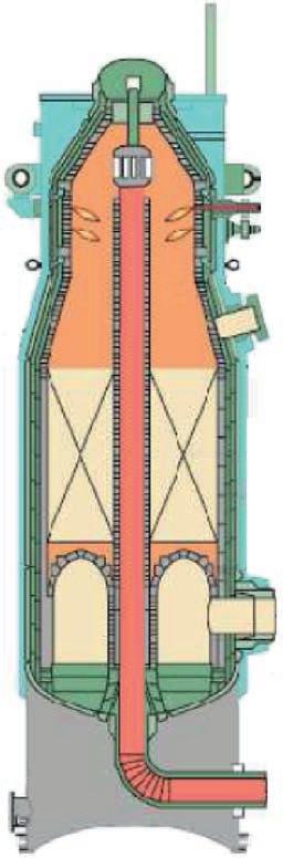
Fig. 32: Secondary reformer
(Source: Leading fertilizer technologies – Ammonia, ThyssenKrupp Industrial Solutions AG).
Process air
Combustion zone
Water jachet
Catalys Refractory
Arch
Process gas
Process gas
The
Uhde dual pressure process
The Uhde dual pressure ammonia process is based on the top-fired primary reformer with a cold outlet manifold, a secondary reformer with a circumferential vortex burner, and one or two ammonia converters, usually in a three bed adiabatic configuration. The ammonia synthesis occurs at two different operating pressures. After natural gas desulphurisation the feed gas is mixed with steam and reformed first in a primary reformer, and then in a secondary reformer. High pressure steam and steam superheating occurs downstream of the secondary reformer. Shift conversion is accomplished in a conventional scheme based on high and low temperature shift converters, while the CO2 is removed through a BASF-aMDEA or UOP-Benfield process. Remaining carbon oxides are methanated by catalytic methanation down to trace ppm levels.
The synthesis loop has two converters (Figure 33), one uses fresh make-up gas and operates at about 110 bar; a second converter is located in a syntheis loop with higher inerts concentration and works at a pressure greater than 200 bar. Uhde ammonia synthesis converters are based on a radial catalyst bed with indirect intercooling among the beds; the heat exchange is performed with heat exchangers. One feature of Uhde ammonia converters is the capability of extracting the internal heat exchangers without removing the ammonia converter cartridge.
Start-up gas
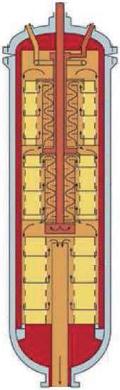
Gas intel
Bypass control
First bed
Second bed
Third bed
Gas outlet
(Source: Leading fertilizer technologies – Ammonia, ThyssenKrupp Industrial Solutions AG).
Thanks to this dual pressure configuration, the syngas compressor has a power consumption similar to a conventional plant. The ammonia separated in the synthesis loop is routed to the refrigeration section and finally to the storage tank.
The Uhde dual pressure process (Figure 34) has been the first in the world to achieve a plant capacity of 3,300 t/d of ammonia.
Fig. 33: Ammonia converter
Desulphurisation
Feed
Process air
Combustion air
Purge
Source: www.thyssenkrupp-industrial-solutions.com
Single pressure ammonia process [15]
As well as the dual pressure ammonia process, Uhde also licenses a standard single pressure ammonia process; its main operating parameters are described below.
As in a conventional process, the feedstock (typically natural gas) is desulphurised, mixed with steam and preheated to 530 580ºC in the mixed feed coil. Once the process gas has been fed to the primary reformer radiant box, it is converted to synthesis gas over nickel catalysts at approximately 39 43 bar and 800° C; the operating steam to carbon ratio is typically 3.0 : 1. At these operating conditions the methane outlet concentration from the primary reformer is 10 13% (dry basis).
The heat required for the steam reforming reaction is provided by forced draft arc burners which use natural gas and combustion air pre-heated to 250 440ºC. The coil arrangement inside the convection section allows a final flue gas temperature
Fig. 34: Dual pressure ammonia process
Ammonia converters
in the stack of 120 180ºC. The process gas coming from the primary reformer is fed, together with air, to the secondary reformer. The process air is mixed with the process gas through a special nozzle system which provides an even mixture of air and gas.
Most of the high pressure steam at 125 bar is generated downstream of the secondary reformer; steam superheating is first achieved in a process steam superheater exchanger, while the final heating to 530 540ºC is performed in the primary reformer coils. The duty of the process steam superheater exchanger is in the range of 15 40% of the heat available between the secondary reformer exit and high temperature shift inlet.
Downstream of the shift converters, where CO is converted to CO2, the syngas is fed to the CO2 removal section, typically based on a BASF MDEA or Benfield system. The CO2 recovery rate is higher than 96%, while the CO2 purity is higher than 99%. After CO2 removal, residual COx compounds are methanated in the methanator in order to generate fresh syngas for the ammonia synthesis. The H2/N2 ratio downstream of the methanator is 2.95.
The synthesis loop is based on a single pressure arrangement and the operating pressure is 140 210 bar. In the single pressure design a three bed ammonia conversion configuration is utilised. The ammonia converter beds are based on a radial design; each bed is filled with small sized magnetite catalyst. Typically the ammonia concentration at the converter inlet is 3 5%, while the ammonia concentration at outlet of the third bed is 20 25%.
The total consumption figure (feed + fuel + electric power) per metric tonne of ammonia produced at an Uhde conventional ammonia plant is in the range of 6.6 to 7.2 Gcal (27.6 30.1 GJ), depending on local conditions (e.g. cooling water temperature) and project specific requirements (such as natural gas price, etc.).
Main markets
Uhde has built plants all over the world, but there are some areas where its activities have been singularly, if not spectacularly, successful. In particular Uhde has developed the North African and the Middle East markets over the last 20 years, becoming a benchmark for the ammonia industry in these emerging markets. Uhde activities have focused in particular on large scale ammonia plants such as the 3,300 t/d ammonia plants built in Saudi Arabia at SAFCO IV and Ma’aden, as well as many “medium” capacity ammonia plants, including eight 1,200 t/d plants in Egypt, two 2,200 t/d units in Algeria, a 2,000 t/d and a 1,500 t/d plant in Qatar, and a 2,000 t/d in the UAE.
Strongest point
As distinct from its many competitors, Uhde (TKIS) is not just an engineering licensor but also has the capability to provide turnkey plats where all project aspects from initial project study, through project financing, engineering, procurement, civil works, erection, commissioning, operation, maintenance and commercial management are directly managed by TKIS as a single supplier.
ThyssenKrupp offices are located in all five continents and most of them have their own engineering capability they are not just representative offices. The company’s success also comes from a wide technology portfolio which, combined with their local presence, guarantees easier access to a large number of customers and countries.

CHAPTER 9 OTHER AMMONIA TECHNOLOGIES
Fabio Sassi, Elio Strepparola
Introduction
In the previous chapters we discussed the birth and evolution of ammonia technologies developed by the major licensors and that are still on the market. This chapter will give a brief description of other processes which have been developed, some of which are still relevant today, and others which have been abandoned.
Fauser process [16]
This was one of the first processes developed in the 1920s, based on the concepts developed by Haber and Bosch a few years earlier. Plants based on this technology were initially built and run by Montecatini, which in 1925 decided to licence the process to third parties. The working pressure of the synthesis ranged between 280 300 barg, depending on the activity of the catalyst.
The main innovative feature of the Fauser process was the utilisation of the heat of reaction for the production of high-pressure steam directly in the ammonia synthesis reactor. The heat was recovered by circulating water at high pressure through tubes placed either between the catalyst beds or directly immersed in the catalyst. The steam was produced at about 20 barg and it was possible to eventually generate about 0.85 tonnes of steam per tonne of ammonia produced. Initially the water circulated by natural convection, but later this was changed to forced circulation through the use of pumps. This choice was made in order to have better control of heat exchange and avoid possible local overheating. The temperature profile in the beds was controlled by the circulating water, and this allowed conversions of around 18 20% at about 300 barg.
Another feature of the Fauser system was the incorporation in a single unit of the gas refrigerant, the heat exchanger and the ammonia separator, mounted one above the other as shown in Figure 35. Thanks to this compact arrangement load, losses were very small and therefore the energy required for recirculation also decreased. Initially circulation was achieved by a dedicated compressor but in later designs there was a move to using an ejector for recirculation of unreacted gas. In this configuration, the synthesis gas was pumped at about 360 barg and then mixed with the circulant in the ejector.
The gas mixture exited at about 300 barg, which corresponded to the working pressure of the reactor.
1) Circulator 2) Ammonia coolant 3), 8) Heat exchangers 4) Water coolant 5) Boiler f) Catalyst 7) Cooling tubes (from Iuliu Moldovan “The technology of mineral fertilizers”, 1969).
1) Circulator; 2) ammonia coolant; 3), 8) heat exchangers; 4) water coolant; 5) boiler; 6) catalyst; 7) cooling tubes.
Source: Iuliu Moldovan “The technology of mineral fertilizers”, 1969.
Fig. 35: Fauser Montecatini ammonia plant
Fauser Montecatini eventually went out of business. The photograph in Figure 36 shows the demolition of the prilling tower following the closure of the Cairo Montenotte (Italy) ammonia plant.
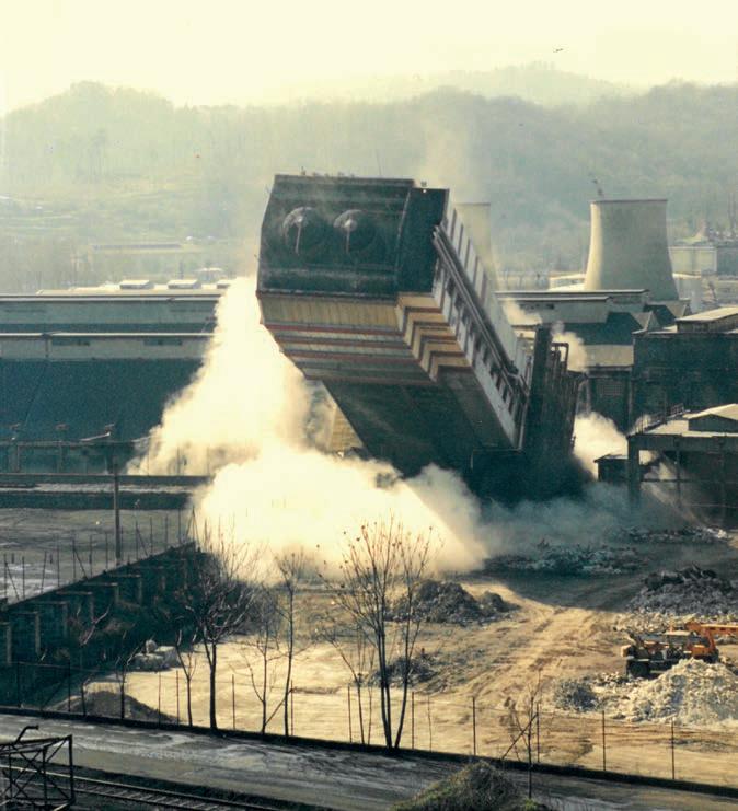
process [17]
The Claude process was invented by Georges Claude in 1918. In 1920 the first pilot plant started up and in the following year the first industrial-scale plant was built.
The French company “Société de la Grande Paroisse Azote et Produits Chimiques” was then founded with the intention of licencing the process.
The special feature of this process, compared to its competitors, was the absence of
Fig. 36: Demolition of the prilling tower at the Cairo Montenotte plant
Courtesy by Mr Lorenzo Pennino.
Claude
synthesis gas recycling. The process operated at about 1,000 bar g, a much higher pressure than competitors. The advantage of such a high pressure is the ability to achieve very high conversions (of the order of 25%) and to be able to condense the ammonia produced with water.
As shown in Figure 37, the process provided for the separation of ammonia downstream of each reaction stage. In this way it was possible to convert up to about 80% of the feed gas. The unconverted gases were used as fuel.
Source: Vaclav Smil, “Enriching the Earth, Fritz Haber, Carl Bosch and the Transformation of World Food Production”. MIT Press, Cambridge, Massachusetts, 2001.
It might be argued that the compression energy requirement in the Claude process was much higher than for its competitors. Claude replied to this objection by explaining that the work required to compress a gas at constant temperature is proportional to the logarithm of the pressure ratio. Therefore if, starting from atmospheric pressure, compression duty up to 200 bar is about 2.3, to reach 1,000 atmospheres the work required is only 3 3.5, once account is taken of lower compressibility at high pressure.
In contrast, by working at high pressure, the efficiency of the catalyst was much higher, and it was not necessary to recirculate the unconverted gases because with a few reaction and separation steps it was possible to convert a high percentage of the feed gas. The main drawback of the process was the mechanical design of the equipment to operate at such pressures, and disposal of the heat generated by the high conversion rates.
Fig. 37: Claude process
Chemico process [18] [19] [20] [21]
In 1929, American Cyanamid’s Chemico (Chemical Construction Company) acquired the Nitrogen Engineering Corporation, which in the mid-1920s had been one of the first US engineering firms to work on the synthesis of ammonia. Up until the 1960s-70s the design of Chemico plants featured a reactor cooled with bayonet tubes (Figure 38). The heat exchange took place co-current with the reagent gases. This design allowed the maximum temperature differential to be obtained and therefore maximum cooling at the entrance of the bed, where the reaction rate is at its maximum. The purpose of this design was to obtain a temperature profile as close as possible to the maximum reaction rate curve. These reactors could have a downstream heat recovery system at 250 psig (17.5 barg) with a recovery of up to 0.95 tonnes of steam per tonne of ammonia.
A) Converter a) catalyst b) heat exchanger c) cooling pipes d) gas inlet e) control T bed inlet (cold shot) f) outlet
B) Temperature profile in the converter C) Ammonia concentration against temperature
Source: Chapter on ammonia, “Ullman’s Encyclopaedia of Industrial Chemistry” Release 2002 6th edition.
The design was later abandoned in order to change to a design similar to the one proposed by Kellogg, i.e. a reactor with adiabatic layers with quench at the exit from each bed. Chemico built a total of 23 plants and is no longer present in the market.
Fig. 38: Chemico tube cooled converter
AB C
ICI processes [18]
Between the early 1980s and 1990s ICI put together a team of engineers with the aim of creating innovative plant layouts for the production of ammonia. Under the guidance of Alwyn Pinto this working group gave birth to the LCA (Leading Concept for Ammonia) and AMV flowsheets.
AMV process
AMV originally stood for Ammonia V: in the early 1960s ICI built three Kellogg plants at its Billingham site which were called Ammonia 1, 2 and 3. In the 1970s a fourth plant was built; Ammonia IV. When design of a new facility began in the 1980s, based on concepts developed by Pinto, it was called Ammonia V, abbreviated to AMV, although the first prototype was actually put into operation in 1985 at the Nitrogen Products Factory (formerly CIL) in Canada. This was followed by other plants in China.
The main feature of this process (Figure 39) consisted of operation with a reduced load on the primary reformer (at a steam/carbon ratio of about 2.8 : 1) and an excess of air in the secondary reformer which allows a methane concentration of about 1% to be reached in the output from the secondary. Excess nitrogen was fed to the synthesis cycle operating at around 90 barg with a very high volume of catalyst when compared with other technologies.
a) Desulphurisation b) Saturation of natural gas c) Process air compression d1) Primary reformer d2) Secondary reformer e) Boiler f) High temperature shift g) Low temperature shift h) Selexol CO2 removal h1) CO2 absorber h2) Regenerator i) Single compression stage j) Methanation k) Cooling and drying l) Circulation m) Hydrogen recovery n) Ammonia reactor o) Colling system
Source: Chapter on ammonia, “Ullman’s Encyclopaedia of Industrial Chemistry” Release 2002 6th edition.
Fig. 39: ICI AMV process
Only the air compressor is driven by a turbine, which receives all the steam generated in the plant and which has an alternator on the same shaft. All other utilities, including the syngas compressor, are driven by electric motors. The syngas compressor is positioned upstream of the methanator in order to exploit the heat of compression to heat the cold gas coming from the scrubber of the carbon dioxide CO2 in the Selexol section.
Another important feature of the process is the fact that about half of the process steam is supplied by the saturation of the natural gas with water in a separate column. The synthesis reactor is designed with three beds with a quench with fresh gas between the first and the second bed and an exchanger between the second and the third. Excess nitrogen and inerts (argon and methane) are removed by purging the gas from the discharge side of the pump, which is then treated in a cryogenic unit that works at the loop pressure. The separate inerts are sent to fuel and the hydrogen recovered goes in aspiration to the circulator. All these features were designed to reduce system energy consumption, which was around (28.5) GJ/ t NH3
LCA process
The Low Cost Ammonia (LCA) process introduced by ICI at the end of the ‘80’s was a somewhat radical change in design philosophy when compared with the highly integrated plants developed from the 1960s onwards. Figure 40 shows the layout of the so-called “core unit”, which includes only the essential sections for production of ammonia (up to 450 t/d). A separate utility section provides cooling, steam and electricity, including the cooling water and demineralised water systems and, if required, could recover carbon dioxide.
Feed gas is purified in a desulphurisation unit operating at a lower temperature than usual, and then passes into a saturator, where part of the process steam is supplied; the remainder is supplied as live steam. The mixture thus obtained is heated in an effluent feed to about 425°C and then fed to the Gas Heated Reformer (GHR) operating at 41 barg. In the GHR the reforming reaction proceeds by absorbing heat from the outgoing hot gases from the secondary reformer. The partially reformed gases at 715°C are sent to the secondary reformer, from where they leave at 970°C and are then cooled to 540°C in the GHR. The concentration of methane is about 25% in output from the GHR and 0.67 from the secondary.
The outgoing gas from the effluent feed at 265°C enters an isothermal shift reactor containing a special copper, alumina and zinc catalyst. The reactor has cooling tubes in which circulate hot water which is later used to saturate the natural gas. Purification of the gas is carried out in a Pressure Swing Adsorption (PSA) unit that removes the CO2, excess nitrogen and most of the CO residue, followed by a methanation section and drying section with molecular sieves.
2.8 bar 12.4 t/h
5.7 bar 7.7 t/h
a) Air compressor b) Air heater c) Hydrodesulfuriser d) Saturation e) GHR f) Secondary reformer g) Shift converter h) Desaturator i) PSA unit j) Methanation k) Molecolar sieves l) Ammonia converter m) Two-stage flash cooling (only one shown) n) Chiller o) Separator p) Flash vessel q) Synthesis gas compressor
Source: “Ullman’s Encyclopaedia of Industrial Chemistry” Release 2002 6th edition.
The synthesis is operated at 82 barg in a cooled tube converter and loaded with the iron catalyst with added cobalt. The purge gas of the loop is fed to the entrance of the PSA unit, while the CO2 is recovered from the off gases of the PSA in an aMDEA section (BASF licence). The process generates very little steam and all moving parts are driven by electric motors. The original goal was to design a system capable of competing with modern high-capacity designs in terms of consumption and specific investment cost and, thanks to the lower energy integration, which was also more flexible during start-up and operation at low loads. Energy consumption was calculated to be around 29.3 GJ/t NH3. ICI was never able to penetrate the ammonia market completely as it had instead managed to do with methanol, but overall, the company has built a total of 28 plants worldwide using various generations of technologies. Among these one AMV plant was built in Canada and three LCA plants, two of them at the former ICI Severnside site, and one in the United States. The company has since undergone a number of divestments and is no longer active in the ammonia market.
Fig. 40: ICI LCA core unit processes
Linde ammonia concept (LAC) [18] [22]
The Linde Ammonia Concept (LAC) process from Linde was marketed in the 1990s and essentially consists of a hydrogen plant with a PSA unit for purifying the synthesis gas produced, a cryogenic unit for scrubbing with nitrogen, and a high-efficiency ammonia synthesis loop. This design was developed to reduce the cost of the plant, which is considerably simplified. Its disadvantage, however, is that the CO2 recovered is not pure enough to be supplied to a urea plant, and therefore this type of process is mainly suited to units for the production of nitrates and/ or ammonium phosphate fertilizers. This principle had already been proposed by other companies but not for world-scale capacity as in the case of Linde.
Figure 41 compares the LAC design with a conventional plant. The main features of the Linde process are:
• Elimination of three catalyst steps, with consequent reduction in the total catalyst volume required for the plant to about half that of a conventional plant.
• Generation of a synthesis gas free from inerts, making the loop more efficient and less expensive. The absence of inerts also means that a purge is not required.
• It is not necessary to treat the process condensate, as this is used in the isothermal shift to generate process steam.
• Casale synthesis reactor with the known advantages of high conversion and low load losses thanks to axial-radial technology.
Fig. 41: Comparison between conventional and LAC
The specific energy consumption declared by Linde is about 28.5 GJ/t NH3. The first LAC plant was commissioned in 1998. To date, four such plants are in operation with capacities ranging from 230 to 1,350 t/d.
Fluor process [18] [23]
The flowsheet developed by Fluor was characterised mainly by the design of the carbon dioxide removal section, which was based on physical absorption with propylene carbonate. Here the regeneration of the CO2–rich solvent was achieved by decreasing the pressure and finally by stripping the solvent with gas. Part of the CO2 was recovered under pressure. In this way, regeneration does not require heat and therefore the heat available downstream of the low temperature shift can be used in the refrigeration system, which is based on ammonia absorption units instead of a traditional compressor. Consumption rates estimated for this layout were around 32.6 GJ /t NH3. Fluor has built two plants based on this technology.
GIAP process [24]
GIAP, which stands for “Gosudarstvennogo Instituta Azoti Promishlennosti” or “State Nitrogen Industry Institution”, developed a domestic Russian technology for the production of ammonia, based on the Kellogg process. The front end of a GIAP plant very closely follows Kellogg plants: the main difference is in the working pressure of the synthesis loop, which was around 300 barg. This high pressure allowed a first condensation step using only air (or water), followed by a second using an ammonia chiller. Another feature of these plants was the use of absorption coolers instead of cooling cycles based on ammonia compression as was the case in the technologies proposed by all other licensors.
GIAP built 37 plants from the early 1960s through the 1980s. It exited the ammonia plant market just before the collapse of the Soviet Union in the early 1990s.

CHAPTER 10 LEADING PLAYERS
Fabio Sassi, Elio Strepparola
The development, engineering and optimisation of synthetic ammonia production were linked, especially in the pioneering period at the beginning of the last century, to a group of individuals favoured with particularly brilliant personalities and abilities. Subsequently, once the technologies were confirmed as valid, reliable and applicable industrially, the key players changed, moving from the individual to the research team, to the engineering company or industrial complex, to multinational chemical companies, and finally engineering contractors.
The individuals, aided by their technical and scientific genius and foresight, were the Prometheus-like pioneers of an industrial product which has contributed considerably to the human welfare. For this reason we believe it is important to include brief profiles of the key personalities who have contributed to the development of modern industrial ammonia production methods. We start, however, with two scientists on whose shoulders they all stand.
Antoine Laurent Lavoisier
Born on August 26, 1743 in Paris, Antoine Laurent Lavoisier attended the Collège des Quatre-Nations from 1754-1761, studying chemistry, botany, astronomy, and mathematics. A chemist, naturalist, astronomer, economist and tax collector, from the 1760s Lavoisier helped shape a revolutionary new idea of chemistry.
One of Lavoisier’s most important experiments demonstrated that combustion is a process that involves the combination of a substance with oxygen, as is also the case for the breathing of animals and plants and the rusting of metal. He also discovered that the inflammable air of Henry Cavendish which he called hydrogen (from the Greek “former of water”), combined with oxygen to produce a dew which, as Joseph Priestley reported, appeared to be water.
Through, in 1777, Sur la combustion en general, and in 1778, Considerations générales sur la Nature des Acides, he demonstrated that the ‘’air”, responsible for the combustion, was also the source of acidity. In 1779 he called a part of the air “oxygen” (from the Greek “acid-forming”), and the other “nitrogen” (from the Greek “without life”). In Réflexions sur le Phlogistique, published in 1783, Lavoisier showed that the phlogiston theory of combustion was incorrect.
Lavoisier’s experiments were among the first truly quantitative chemical experiments ever conducted. Together with the French chemist Claude Louis Berthollet and other scholars, Lavoisier devised a chemical nomenclature which serves as the basis of the modern system. He described the this in his Méthode de nomenclature.
Lavoisier’s fundamental contributions to chemistry were the result of a conscious effort to group all experiments within a single structure of theories. For the first time the modern notion of elements was set out systematically. The few elements
known to the alchemists and proto-chemists made way for the modern system, and Lavoisier described reactions through chemical equations that respected the conservation of mass. He also founded the first chemistry journal, Annales de Chimie Lavoisier had been since 1769 a Fermier Général, i.e. a collector contracted for various types of taxes: when, at the end of 1793 the arrest was decreed of all the managers of the Ferme Générale, the revolutionary court sentenced him to death and Lavoisier was executed on the guillotine on May 8, 1794.
Justus von Liebig
Justus Liebig was born in Darmstadt on May 12, 1803, and from 1819 1822 attended the universities of Bonn and Erlangen. He then went to Paris, to work at the laboratory of Gay-Lussac. In 1824 he was appointed associate professor and in 1826 full professor in Giessen. There he created a laboratory that became among the most celebrated in the world. In 1852 he was appointed lecturer at the University of Munich.
Liebig had surprisingly varied scientific interests. Some 318 of his memoirs cover a wide variety of topics, but especially concerning organic chemistry. He perfected the methods of elemental analysis of organic substances, succeeding in determining with certainty the empirical formulas of many organic compounds whose constitutions were hitherto uncertain.
Liebig, applying chemistry to the study of one of the main problems of plant physiology, that of plant nutrition, overturned the prevailing theories of the time and demonstrated that the so-called humus theory, according to which plants absorb organic substances in the soil coming from the decomposition of plants and existing animal bodies, could not be correct. Instead he posited that plants rely on nitrogen and carbon dioxide obtained from the atmosphere, and that the soil contained essential inorganic nutrients. His ideas were embodied in a law of the minimum. Liebig was not always correct, and sometimes changed his mind. However, he was without question the leading promoter of agricultural science. He accepted, after much debate, that mineral fertilizers were necessary for addition to the soil. It is to the ideas of Liebig that we owe the practice of mineral manuring and the use of chemical fertilizers. He also showed how to make natural phosphates, laying the foundations of the superphosphates technology.
Throughout his eclectic career he also investigated physiological chemistry and fermentation and invented the famous meat extract that bears his name. Liebig was ennobled in 1845. He died in Munich on April 18, 1873 after a life spent in applied chemical research.
Carl Bosch
Carl Bosch, Figure 42, was born in Cologne on August 2, 1874. He originally studied materials and mechanical engineering, later moving on to study chemistry in Leipzig, which in turn led him to begin work as a chemist at BASF in Ludwigshafen in 1899.
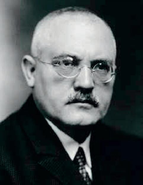
Source: BASF Historical Milestones, BASF.
Bosch had an extensive knowledge of chemistry and physics which helped to further his career at BASF, eventually dealing with all the technologies owned and developed by the German industrial giant.
In the years preceding the First World War he placed on an industrial scale Fritz Haber’s synthetic ammonia invention into an innovative process for the industrial production of ammonia, which, by conversion into nitric acid, was much needed to make Germany’s military-industrial complex independent of imported Chilean nitrate. The Haber method used osmium and uranium as catalysts. Bosch’s team developed an iron catalyst, far less expensive and more readily available. This was the precursor of today’s catalyst system consisting of a mixture of magnetite, protectors and activators. Bosch focused on the development of a process for producing synthetic ammonia at pressures of about 200 atmospheres and 500°C, seeking to make the most of the iron-based catalysts. The nitric acid generated from synthetic ammonia was used to make explosives for military and civil engineering applica-
Fig. 42: Carl Bosch
tions. Most important, however, especially from around 1920, was conversion of ammonia into ammonium sulphate for use as a fertilizer. Later the production of ammonia also led BASF to achieve important results in industrial areas based on high pressure chemistry. Thanks to the success of the ammonia process, Carl Bosch became managing director of BASF.
Although he was a cofounder in 1925 of IG Farben, one of the main financiers of National Socialism in Germany, Bosch tried in every way to protect and assist Jewish colleagues and co-workers, starting with Fritz Haber. Bosch was recipient of many international awards, culminating in 1932 with the Nobel Prize (jointly with Friedrich Bergius) for his development of high-pressure chemical processes. Carl Bosch died in 1940.
Luigi Casale
Luigi Casale, Figure 43, was born in Langosco Lomellina, Italy, in 1882, the third of eleven children of Santino Casale, administrator of the properties of the earls of Langosco. He graduated in chemistry from the University of Turin in 1908 and remained there for several years as an assistant and then as an auxiliary in the Institute of General Chemistry and Electrochemistry.
During 1912-1913 he undertook research at the University of Berlin under the leading physical chemist Prof. Nernst. At the outbreak of the First World War, Casale was sent to Naples to join the Institute of Pharmaceutical Chemistry as a member of a group researching poison gases, but incipient poisoning forced him to end this work. After the war, in spite of his serious illness, he worked on the ammonia synthesis, a project to which he dedicated all his energies from that time onwards. In 1919 Casale, following on from the work of Haber and Bosch, developed his own process for the synthesis of ammonia. Unlike the Haber-Bosch process, the Casale process was based on pressures approaching 800 atmospheres.
The first industrial-scale pilot plant using the Casale process began operation in 1920 in Terni, in central Italy. In the following year, thanks to support from the Gutzwiller Bank in Basel, he founded Ammonia Casale SA in Lugano, Switzerland, and immediately began to commercialise his process, through licensing arrangements, as well as optimising it for industrial application. Unfortunately, the poisoning that Casale he had suffered during the war years had so undermined his health that in February 1927 he was struck down at only 45 years old by a sudden collapse. Albeit without his guidance, the company’s subsequent progress was rapid, as a result of worldwide demand for nitrogen products, and, Ammonia Casale gained in importance and international visibility.
Prof. Miolati (whose assistant Casale was at the University of Turin) said about

Fig. 43: Luigi Casale
Luigi Casale, just after his death, at a Conference in February 17, 1927 at the Institute of Chemistry of the Prague Polytechnic School:
“It was wonderful to see this young man, without experience of life in industry and finance, unaware of their surprises, overcoming difficulty after difficulty; developing a first class technical sense, I might say almost an intuition, of the first order, showing his knowledge of men; selecting his co-workers one by one; placing his great enterprise on a sound financial basis; and withal remaining ever serene, modest and kind; happy in the intimacy of his family and the circle of a limited number of friends.”
Georges Claude
Georges Claude was born in Paris on September 24, 1870, and began technical studies at the School of Physics and Chemistry in the French capital, which soon led him to applied physics. He specialised in the production of industrial gases such as oxygen and nitrogen through the process of liquefying air. In addition to gases derived from air, Claude’s field of specialisation ranged from acetylene and its related transport problems, to discharge lamps linked to halogen gases. He invented neon lighting.
In 1917, during the First World War, Georges Claude completed the development of a very high-pressure process for the production of ammonia. The process involved working at 1,000 atmospheres in order to exploit the best approaches to equilibrium and best conversion yields. Claude’s experience allowed him to remove the heat produced by the reaction and thus obtain high yields. A major advantage for the time was the use of relatively small equipment to achieve what were large yields.
During the Second World War he applied his technical capabilities to the design of German V2 rockets, and because of this was briefly imprisoned as a collaborator after the war. However, until his death in 1960, he remained a small-scale technology entrepreneur.
Giacomo Fauser
Giacomo Fauser, Figure 44, was born in Novara, Italy, in 1892. At the end of the First World War he graduated in mechanical engineering, guided by experience gained in the family business a small industrial foundry.
At the time, mechanical engineering courses at the Milan Polytechnic also included the design, construction and operation of chemical plants. Fauser’s particular aptitude led him to stand out in these areas, while the family business allowed him
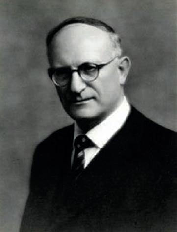
to study the optimisation of autogenous welding. Oxygen is a fundamental requirement for these welds and Fauser, with a very modern interpretation of technical and economic optimisation, developed an efficient system for obtaining oxygen by electrolytic dissociation of water using electricity, at times when the factory was not operating: fortunately for Fauser, the electricity supply had to be paid for even if it remained underutilised (e.g. during evenings or public holidays).
The result was the Fauser electrolytic cell, which produced pure hydrogen as a by-product of the process. Fauser was one of the first, after Bosch, to succeed in developing a process for the production of ammonia (1920), circumventing the BASF patent. Fauser generated nitrogen by the combustion of hydrogen with air.
Ammonia was produced from the hydrogen-nitrogen mixture in special catalysis chambers, with intermediate cooling to optimise the conversion. Fauser worked alone, using instruments and experience at the Fauser foundries. The first equipment used, such as reactors and separators, were surplus wartime equipment: the ammonia reactor was in fact a 320 mm howitzer.
Fauser’s results attracted the attention of the Montecatini company, which immediately proposed industrial development of this brilliant and potentially lucrative process. Giacomo Fauser subsequently made his reputation as an eclectic and prolific designer. From the early postwar years to the 1950s, he developed a series of processes ranging from nitric acid to urea (both related to ammonia), venturing into hydrocarbons and heavy oils. From 1935 he conducted industrial trials on the
Fig. 44: Giacomo Fauser
exploitation and desulphurisation of heavy oils in Albania, then an Italian possession. His ability and success brought a series of awards, and commendations, starting with the Italian National Research Council (he was appointed a member by Guglielmo Marconi) to a long series of honorary degrees.
When Giacomo Fauser died in 1971 he was credited as one of the founders of modern Italian industrial chemistry.
Henry Louis Le Chatelier
Le Chatelier was born in Paris on October 8, 1850 into a middle-class Catholic family. He enrolled at the École Polytechnique in 1869. The following year he took a mining engineering course at the École des Mines in Paris, graduating in 1873.
Le Chatelier initially remained at the École des Mines as a teacher and focused on improving safety in French mines.
The early works of Le Chatelier led him towards an experimental analysis of thermodynamics. In 1884 he set out the general principle of chemical equilibrium; that systems in equilibria tend to minimise the changes imposed on them. This has become known as the Le Chatelier Principle, which has proved to be invaluable for the development of more efficient chemical processes.
The focus of Le Chatelier then turned to the challenge of how to apply the science of chemical thermodynamics to the development of industrial processes. He arrived at the important insight of how to optimise the production of ammonia on an industrial basis by applying his principle of chemical equilibrium. However, he did not follow up this work after his apparatus blew up.
Le Chatelier’s career was largely dedicated to the development of a systematic approach to the organisation of the relationship between pure science and industrial production. Similarly, his interest in industrial applications of chemistry led him to perfect the welding and cutting of metals.
In 1907 Le Chatelier was elected to the French Academy of Sciences. During his academic career he devoted most of his time to directing the research work of his students at the Sorbonne and Ecole des Mines. He died on September 17, 1936.
Fritz Haber
Fritz Haber, Figure 45, was born in 1868 in Breslau, modern Wroclaw, in Poland, then part of Prussia. He was the only son of a wealthy seller of dyes and other chemical products and this allowed the young man to follow his scientific interests instead of continuing to run his father’s business. He became interested in the study of chemistry, at the time one of the scientific disciplines in which Germany
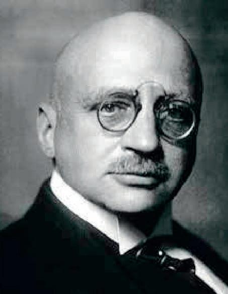
excelled, and in 1891 gained his doctorate, based on research in organic chemistry, at the University of Berlin. After a brief experience working in chemical companies, he decided to embark on an academic career. Haber, after graduation, undertook research at the most important German chemical institutes, and also spent a short time at Zurich’s polytechnic (ETH). His areas of interest encompassed physics, chemical physics and physical chemistry. In 1894, he joined the Karlsruhe Technische Hochschule. His first years there were spent in making a name for himself, with research into the chemistry of combustion and electrochemistry.
His first encounter with ammonia was in 1904, with an experimental study on equilibrium conditions. It was the beginning of a long process that five years later led him to file the first patent for his famous apparatus for ammonia synthesis.
In 1905 he published a book on thermodynamics related to technical gas reactions, in which he presented his discoveries concerning the production of small amounts of ammonia starting from nitrogen and hydrogen at very high temperatures (1,000°C). He pointed out, however, the reaction could be improved only if a suitable catalyst could be found. This was not possible at the time. Following this very early research, he then focused on the development of a catalytic process for producing synthetic ammonia at pressures of about 200 atmospheres and 500°C. This work was completed in 1909.
Fig. 45: Fritz Haber
Source: BASF Historical Milestones, BASF.
Haber’s rare and expensive osmium and uranium catalysts were replaced in industry by less expensive and more readily available magnetite iron, containing, protectors and activators. Haber’s invention, as described above, was placed on an industrial scale by Carl Bosch at BASF.
From the 1920s, Haber, among other topics, became interested in insecticides. Two of his colleagues later developed the process for the synthesis of the hydrocyanic acid product known commercially as ‘Zyklon B’. It was used widely for the disinfestation of lice and other pests, but was subsequently used in Nazi death camps. Haber’s research work between 1916 and 1933 was undertaken at his Kaiser Wilhelm Institute of Physical Chemistry and Electrochemistry in Berlin. In April 1933, the Nazi’s first anti-Semitic racial laws required that Haber dismiss his Jewish co-workers, though because Haber, from a Jewish family, had served in the army he was allowed to continue. After dismissing his colleagues, Haber handed in his own resignation. Fritz Haber moved to Great Britain, where he took up a position at the University of Cambridge. In 1934 he decided to move to Mandate Palestine, in the town of Rehovot (now Israel), but during the journey he suffered a severe heart attack in a hotel in Basel, where he died. The success of his research earned Haber the 1918 Nobel Prize.
He also received numerous awards. Scientific research institutes have been names in his honour. Haber is associated with both the synthetic ammonia process and his First World War work on the deployment and development of toxic gases.
Morris W. Kellogg
Morris Kellogg, Figure 46, was born in New Jersey, U.S.A., in 1873 and studied at the Stevens Institute of Technology, where he emerged as a charismatic leader, active in the social sphere. After graduating, his first job was with a company that traded and supplied material for plumbing and civil plant engineering in New York. After a few years his growing aptitude for business and enterprise led him to become bored with this job, since he was making no progress in his career.
In 1900, with share capital of only $2,750, he registered the M.W. Kellogg Company, aided and funded by former fellow students of the Stevens Institute of Technology, his first co-workers.
His previous work in the area of civil engineering and hydraulics helped Kellogg to enter the rapidly growing energy generation industry. The experience he gained there led him to understand that you could not just provide materials without engineering assistance, prefabrication of piping and installation by an experienced workforce. In the 1920s he diversified into the chemical industry, aligning his business closer to his previous engineering studies and succeeding, during the Second
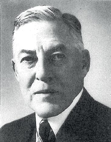
World War, in designing and building important plants for fuel production for Allied combat aircraft. The next step was a contract for work on the Manhattan Project, which led Kellogg to head one of the largest engineering projects in the world. ‘Show me something new’ was the slogan with which he approached any business model focused on engineering.
After the war he further diversified the company’s business thanks to his enterprise and intelligent choice of co-workers and those who were to become future high-level executives. In spite of the company’s varied markets, Kellogg also remained close to his roots, keeping the production and marketing of pipes as a business area for at least 70 years as a memory of the first steps in his career.
Carl von Linde
Carl von Linde, Figure 47, was born in Franconia, Germany, in 1842. After graduating from high school in the city (today the Carl-vonLinde-Gymnasium), he studied at Zurich Polytechnic (ETH) from 1861, where Rudolf Clausius, Gustav Zeuner and Franz Reuleaux were his teachers. Interestingly, he ended his education in 1864 without a diploma because he was expelled following a student protest. He joined the Baumwollfabrik in Kottern, Kempten, in the same year. Not long after he decided to move to Munich, working in the technical department of locomotive manufacturer Krauss & Comp., of Georg Krauss.
Fig. 46: Morris W Kellogg
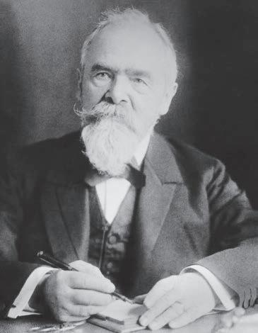
In 1868 he found a job at the Polytechnischen Schule München, the current Technical University of Munich, where at the age of 26 he became associate professor of general thermodynamics. In 1872 he was appointed a full professor of mechanical construction, and established the first mechanical engineering laboratory in Germany, where, among others, Rudolf Diesel studied.
In 1871 he published an essay on refrigeration, thereby founding modern refrigeration technology. Distilleries and breweries across Europe became interested in the new technology: first, in 1877, Dreher in Trieste, Mainzer Aktien-Bierbrauerei, Spaten in Munich, Heineken in the Netherlands, and Carlsberg in Denmark.
On June 21, 1879, along with two distilleries and three other partners, he founded the Gesellschaft für Lindes Eismaschinen AG, today’s Linde AG, and soon the company became a leader in European refrigeration. Manufacturers of refrigerators for food and various ice makers all contributed to the growth of Linde. The technology was also used for creating ice rinks, in dairies and by producers of chlorine and sodium chloride. The brand developed; in 1890 the business flourished and in the same year Linde left the board of directors, returning from 1892 to 1910.
In 1895 Linde succeeded in creating the Linde process, reaching temperatures close to absolute zero, and split air into oxygen and nitrogen through fractional distillation: in 1901 he created an industrial plant to produce oxygen, and from 1903 nitrogen, which eventually allowed the emergence of the nitrogen fixation industry.
Fig. 47: Carl von Linde
Linde was a member of scientific and technical societies such as the Physikalisch-Technische Reichsanstalt and the Bayerische Akademie der Wissenschaften, and President of the Deutschen Kältevereins (DKV). He was also among the founders of the Deutsches Museum. He was presented by Leopold of Baviera in 1897 with the Order of Merit of the Bavarian Crown. Finally, in 1916 Linde was recipient of the first Werner-von-Siemens-Ring. He died in 1934.
Haldor Topsøe [14]
Haldor Topsøe, Figure 48, was born on May 24, 1913, in Copenhagen, Denmark. He studied chemical engineering at the Technical University of Denmark (DTU). Topsøe received a rigorous scientific education and developed his interest in chemistry and catalysis during his studies in physics with Nobel laureate Niels Bohr at what became the Niels Bohr Institute in Copenhagen.
There the young Topsøe realised for the first time the potential of catalysts. Niels Bohr was more than just a professor for Topsøe, since he was first and foremost a family friend and later a real mentor. Bohr and J. N. Bronsted, another great Dan-
Fig. 48: Haldor Topsøe
ish scientist, imparted to Haldor Topsøe a deep appreciation for the scientific approach to problem solving, which the latter in turn conveyed to those joining the company he founded in 1940. This was Haldor Topsøe A/S, which became one of the most successful companies in the field of heterogeneous catalysis. Currently it is one of the undisputed leaders in the science of catalysis and process engineering in the world.
The central figure of the company was undoubtedly Dr. Topsøe, who remained president of the company until his death after a brief illness on May 20, 2013, four days before his hundredth birthday. Haldor Topsøe always put all his enthusiasm, commitment and intellect in support of his company, while running the risk of increasingly concentrating power and responsibility for all activities upon himself. As he said in an interview in 2010 for the Annual Review of Chemical and Biomolecular Engineering, the company’s focus has always been to create new knowledge through basic research and turn it into something that could generate business. Obviously research was always conducted in an area where a potential industrial use was anticipated, especially in catalysis. The company’s website declares: “knowledge is the basis of development.”
Friedrich Uhde
Friedrich Uhde was born in Germany on July 12, 1880 and received a technical training at first and second grade technical colleges and through continuous internship in small local firms. He then went to work at different coking plants, first as a designer and then as department manager, later to become director of a factory in Lorraine. In that position he promoted the development of the nitric acid production process based on catalytic combustion of ammonia, becoming known in Europe as a pioneer in industrial chemical engineering. After the First World War, having lost his job when Alsace and Lorraine were annexed to France, Uhde founded the engineering contractor “Friedrich Uhde Engineering”. In the early 1920s, its main focus was the design of large-scale ammonia and nitrogen fertilizer plants, using ammonia technology based on the Mont Cenis Uhde low pressure process, developed independently on the basis of catalysts with a ferrocyanide base. Uhde designed nitric acid plant, including for the Soviet Union. Things went well for Uhde, one of the first companies of its kind arising from the vision of a single entrepreneur, and up to the beginning of the Second World War his company licensed and built 28 ammonia plants with capacities of 100-120 tonnes per day. The company headquarters were in Dortmund. During the war Uhde’s engineering company cooperated in the production of the synthetic fuel necessary for Germany’s war effort.
The period immediately following the war saw Friedrich Uhde removed from his creation. However, once the Allies understood that Uhde was an important component of German and European reconstruction, he was reinstated as head of his company, ready for its relaunch.
Uhde worked actively up to the age of 72, before handing over management to his son Hans, while remaining a member of the board. He passed away in 1966, having demonstrated tremendous technical and entrepreneurial resourcefulness during one of the most challenging times for both modern Europe and Germany.
Umberto Zardi
Umberto Zardi, honorary president of Casale SA, Figure 49, was born in Bologna, Italy, on July 29, 1929 and, after classical studies in high school, graduated in his home town in mechanical engineering .
He was immediately hired by Montecatini in Milan to handle the development, engineering and marketing of urea technology as part of the company’s inorganic division. For a decade (1954-1964) he worked in research and technological development, always cultivating the pioneering spirit that later became the primary and decisive factor in the ongoing success of Ammonia Casale.
When he no longer felt the incentive towards innovation that had once driven Montecatini, Zardi moved in 1964 to Snamprogetti. Here he successfully developed the new total recycle stripping technology for the urea process, making Snam-
Fig. 49: Umberto Zardi
progetti one of the largest licensees for urea in the world, with more than 130 plants built. He remained head of the inorganic engineering division until 1978. During his stay at Snamprogetti numerous patents on urea were filed in his name and about 20 industrial plants built.
In 1978 Umberto Zardi accompanied Francesco Salimbeni, the then CEO of Snamprogetti, in a new development venture in Switzerland the Ingeco [originally the INGegneria E COstruzioni] plant engineering company that had acquired the old Ammonia Casale, itself driven completely out of the market for at least a decade.
Ammonia Casale had been founded in Lugano in 1921 by Luigi Casale, backed by the forward-looking Gutzwiller bank in Basel. Based on the original patents of Luigi Casale, 120 first-generation plants were built worldwide. In the early 1980s, it was another bank, the Banca del Gottardo, that funded the new Ammonia Casale. There, with an approach based firmly on research and innovation, Umberto Zardi created a working group of fifteen to twenty highly talented people, “the boys of Via della Posta”, who were to form the core of a revival that would bring international success to the company.
Following granting of Ammonia Casale’s 1983 US patent for an axial-radial flow reactor, it became a best-seller: today there are more than 250 reactors of this type all over the world.
Through a culture of innovation pushed to its limit, and with the working group of highly motivated engineers and designers, Zardi took Casale forward to become the only company in the world to hold such a wide range of closely related technologies, involving ammonia, methanol, nitric acid and derivatives, urea and melamine. The various groups are now consolidated in Casale SA, which continues to promote the modernisation and construction of new plants, as licensee, designer, and builder.
Following the success of the axial-radial flow reactor, Casale, via Umberto Zardi and G. Pagani filed numerous industrial patents, including 27 for ammonia and 18 for urea. Zardi still holds the position of president of Casale SA and his daily presence in the office is a constant example to and stimulus for all Casale personnel.

CHAPTER 11 CONCLUSION
The importance of ammonia for population growth
We have seen that the massive growth in the production of nitrogen-containing fertilizers that have sustained the unprecedented increase in the human population has been made possible by synthetic ammonia production.
Besides, this has allowed the development of the modern chemical industry highlighting the crucial role that the specific know-how plays in the realization of large industrial complexes in an efficient and safe way, respectful of the environment. No other discovery, technical or scientific, has had the same impact on the progress of humanity.
Bibliography

[1] Ward, Bess: The Global Nitrogen Cycle. In Fundamentals of Geobiology (1st ed.), Blackwell Publishing Ltd (2012).
[2] Liaw, Y. P.; D. L. Sisterson; N. L. Miller: “Comparison of field, laboratory, and theoretical estimates of global nitrogen fixation by lightning”. Journal of Geophysical Research 95, 2248922494 (1990).
[3] Ericksen, G. E.: “Geology and Origin of the Chilean Nitrate Deposits”. USGS (1981).
[4] “World Population Prospects: The 2015 Revision. Key Findings and Advance Tables.” Working Paper No. ESA/P/WP.241. United Nations, Department of Economic and Social Affairs, Population Division (2015).
[5] “Of rice and men”. The Economist, March 11th-17th 2017, 6061.
[6] Smil, Vaclav, “Enriching the Earth, Fritz Haber, Carl Bosch and the Transformation of World Food Production”, p. 47. MIT Press (2001).
[7] Bosch, Carl: “Nobel Lecture, May 21st, 1932”
[8] Dr. Jaeger Klaus, Dr Korkhaus Juergen: “The ammonia process. Originator for the High Pressure Technology in the chemical industry”, BASF
[9] Miolati, A.: “L’ammoniaca sintetica ed il processo Casale,” L’Universale, Tipografia Poliglotta, Roma, 1927, p. 24

[10] Cariati Vittorio, Cavallone Sergio, Maraini Emilio, Zamagni Vera: “Storia delle Società italiane di Ingegneria e Impiantistica”, il Mulino, Bologna, 2012.
[11] Cariati Vittorio: “Nata due volte – L’avventura bella dell’Ammonia Casale”, Impiantistica Italiana, Anno XXII, N° 5, settembre-ottobre 2009
[12] Multhaup, Robert H. and Eschenbrenner, Gunther P.: “Technology’s Harvest, Feeding a Growing World Population”. Gulf Publishing Company Book Division P.O. Box 2608, Houston Texas, 1996.
[13] Haldor Topsoe and Manos Mavrikakis: “A conversation with Haldor Topsøe”, in Annu. Rev. Chem. Biomol. Eng. 3:1-10, 2012
[14] Larsen, Thomas: “Haldor Topsøe – a portrait”, Gyldendal Business, 2013
[15] Appl, Max: “Ammonia, methanol, hydrogen – Modern production technologies”, Nitrogen
[16] Moldovan, Iuliu: “The technology of mineral fertilizers”, 1969
[17] Partinton J.R.: “The nitrogen industry; 1923”; pag 174
[18] Ullmann Encyclopedia of Industrial Chemistry (2002)
[19] Chemico converter J. B. Allen, in “Chem. Process Eng.” (London) 46 (1965) no. 9, p. 473
[20] Hein, L. B. in “Chem. Eng. Prog.” 48 (1952) no. 8, 412.
[21] Zayarnyi, N. S. in “Int. Chem. Eng.” 2 (1962) no. 3, 378
[22] Linde LAC Process J. Ilg, B. Kandziora, “41st AIChE Ammonia Safety Symp”., Boston 1996.
[23] Zardi U., Antonini A., Ammonia Technology: “State of the art and new developments. Nitroge”n 122 (1979)
[24] Semenov, V.P. “Ammonia production” 1985
[25] Donkin, W. F.: “On the direct synthesis of ammonia”. Proceedings of the Royal Society (May 1 1873).
[26] Thomas, Hager “The alchemy of air. A Jewish Genius, a Doomed Tycoon, and the Scientific Discovery That Fed the World but Fueled the Rise of Hitler”. Harmony Books. (2008)

155
pag. 158: Casale headquarters located in Lugano
Coordination Adverteam - NEXT Group
Editorial Coordination Casale, Luca Bianchi
Graphic Design Adverteam, Alberto Villa
Printing Arti Grafiche Larovere
For the first time in history, humanity has freed itself from the spectre of recurrent famines thanks to a fundamental discovery: the synthesis of ammonia. The book traces the salient stages of this intellectual adventure and engineering feat as well as it presents the stories of those who made it possible.