
Document Title: Function Group: Information Type: Date: Component locations 200 Service Information 2014/5/5 0
Profile: WLO, L120G [GB]
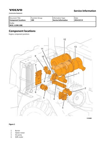
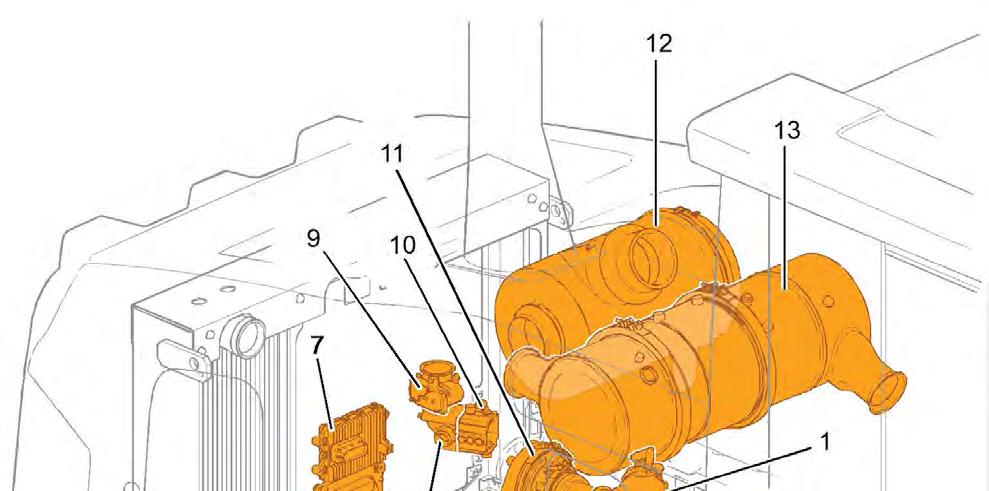
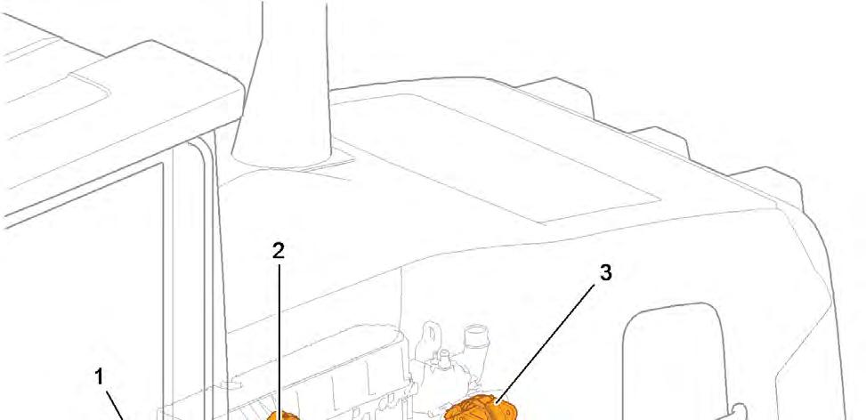
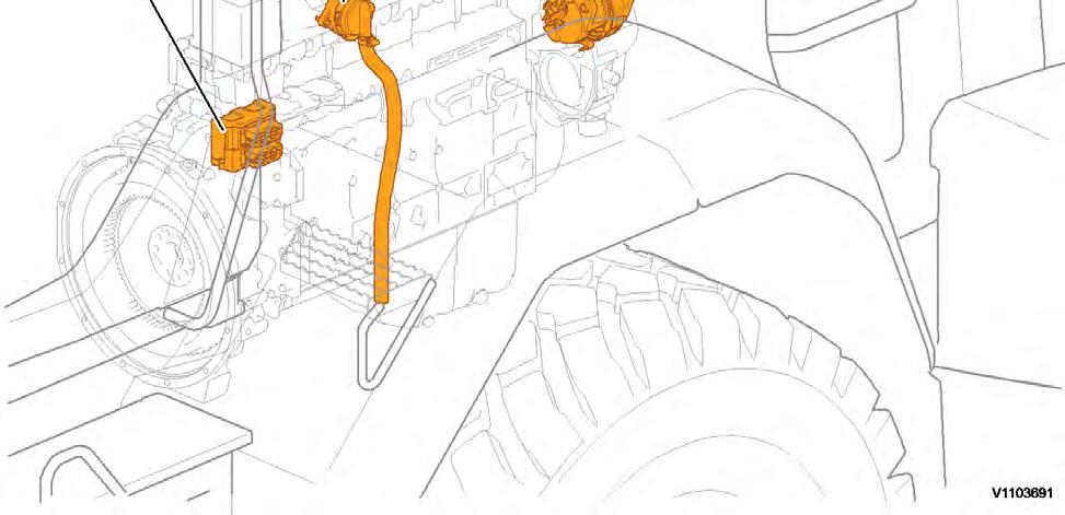
Component locations
Engine, component positions

Mixing chamber
Inlet throttle
Preheater
Turbocharger
Air cleaner
Muffler
Electrical connections, grouping point
Crankcase ventilation, separator
Alternator
Document Title: Function Group: Information Type: Date:
Engine, description 200 Service Information 2014/5/5 0
Profile: WLO, L120G [GB]
Engine, description
Engine D8H is a straight six-cylinder, four-stroke, turbocharged diesel engine with direct injection and intercooler. The engine meets governing legislation according to Tier 4 interim for exhaust emissions.
The engine features a Common Rail Fuel System controlled by the Engine Electronic Control Unit (E-ECU). The engine with ACT (Advanced Combustion Technology) features split injection and turbocharger with mechanical wastegate. The Exhaust Aftertreatment System (EATS) is equipped with a Diesel Oxidation Catalyst (DOC) and a Diesel Particulate Filter (DPF) to reduce the particulate content in the exhausts. Cooled Exhaust Gas Recirculation (EGR) reduces NO contents and reduces emissions. All electronic functions in the engine are controlled by Volvo's Engine Management System, EMS2.2.
For more information, see:
220 Lubrication system, description
230 Fuel system, description
250 Inlet and exhaust system, description
254 Exhaust Aftertreatment System, description
255 Turbocharger, description
260 Cooling system, description
293 Exhaust Gas Recirculation (EGR), description
The cylinders are numbered in sequence, starting at the flywheel. Ignition order: 1-5-3-6-2-4. The engine's rotational direction is counter-clockwise, seen from the flywheel side.
Engine identification
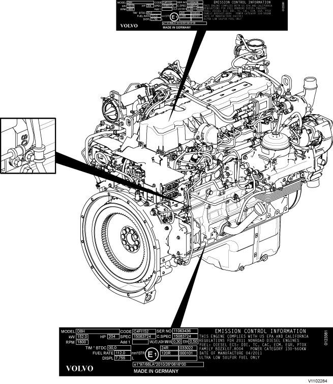
Identification plates
The engine's serial number is stamped on the cylinder block's side. The identification plates on the cylinder block's side and on the valve cover contain model designation, serial number, manufacturing country, recommended fuels, and so on. The identification plates also include emission-related supplementary information. The engine's model designation and serial number must be indicated when ordering spare parts.
Engine protection
The ECU contains functionality designed to protect the engine from damage during extreme operating conditions or from further damage when an essential engine component fails. There are several proactive functions, and different applications have different functions activated. The functions that can be activated are:
High coolant temperature
High inlet manifold air pressure
High inlet manifold air temperature
High oil temperature
Low oil pressure
Low coolant level
High temperature of cooled EGR exhausts after the EGR-cooler
High crankcase pressure
High temperature of EGR actuator
High soot load
High differential pressure across Diesel Particulate Filter (DPF)
High exhaust temperature
High ECU temperature
High DPF temperature
EATS air pump failure
Various protective actions such as warning lights, engine torque reduction, engine speed limitation, and vehicle speed limitation may be taken when the above functions reach dangerous levels that may damage the engine. In order to always allow the operator to move a machine away from an unsafe situation, there is a delay of at least 30 seconds before the protective actions (such as forced idle and forced shutdown) are activated after a Key-ON. If the engine has been forced to shut down or forced to idle due to an active engine protection function, the operator can obtain a 30 second delay by powering down the EMS with a Key-OFF for 7 seconds and then a Key-ON (the EMS is powered down by the Vehicle-ECU (V-ECU) after the ignition key has been in its OFF position for approx. 7 seconds). In addition to the above protective functions, other software functions may request engine protection, such as:
High Altitude (ensures that high compressor charge-air temperature is never reached)
Low Coolant Temp
Crank Sensor Failure
Gear Ratio
Regeneration
Warning lights
There are two levels for warning lights, an amber caution light and a red stop light.
The amber light indicates a warning situation
The red light indicates that the vehicle must be stopped.
For more information, see 387 Central warning
Forced Idle
The engine can be forced to idle speed by the engine protection function. Forced idle is active until conditions triggering the problem are back within the normal working range or the EMS is powered down.
Engine shutdown
The engine can be forced to shut down after conditions have reached levels that may cause engine failure and the machine speed is below a specified value.
Machine speed and engine speed limits
The engine protection function can limit the machine's speed and/or the engine's rpm.
Levels of engine protection
Available proactive functions depend not only on the application but also on what level of protection has been activated for the specific machine. Two levels of engine protection are offered; the standard level is Basic protection and the optional level is Extended protection. The general difference between basic and extended engine protection is that no active actions such as forced idle and forced shutdown will be taken in basic engine protection (with the exception of crankcase pressure that can cause shutdown in either setup). Warnings will be given to the operator regardless of engine protection level.
Parameters
(MCJ) Trimcode CRIN 3.3 injector cylinder 1
(MCK) Trimcode CRIN 3.3 injector cylinder 2
(MCL) Trimcode CRIN 3.3 injector cylinder 3
(MCM) Trimcode CRIN 3.3 injector cylinder 4
(MCN) Trimcode CRIN 3.3 injector cylinder 5
(MCO) Trimcode CRIN 3.3 injector cylinder 6 (FAU) Automatic engine shut off (FAV) Automatic engine shut off, time (YA) Idle speed, setting
Supplementary information
200 Component locations
Function check
17030-3 Parameter, programming
Diagnostics
Detailed information about the following relevant warnings and error codes is available under the diagnostics tab.
Component
Control unit
Message ID MID128 PID98 FX1006 MID128 PID175
SE2203 MID128 PID100
SE2302 MID128 PID97
SE2507 MID128 PID105
SE2508 MID128 PID102
SE2516 MID128 PID412
SE2519 MID128 PID81
SE2603 MID128 PID111
SE2606 MID128 PID110
E-ECU temperature MID128 PPID55
Emergency stop (Engine shutdown) MID128 PPID235
Soot load MID128 PPID326
Document Title: Function Group: Information Type: Date: E-ECU, MID 128, changing non-programmed ECU 200 Service Information 2014/5/5 0
Profile:
WLO, L120G [GB]
E-ECU, MID 128, changing non-programmed ECU
Op nbr 200-068
VCADS Pro VCADS Pro Service Tool
88890180 Interface
88890027 Cable
1. Place the machine in service position 1, see . 191 Service position
2. Connect VCADS Pro and start operation 28423-3 MID 128 ECU, programming.
3. Turn off the voltage with the battery disconnector.
4. Remove the engine cover on the right side.

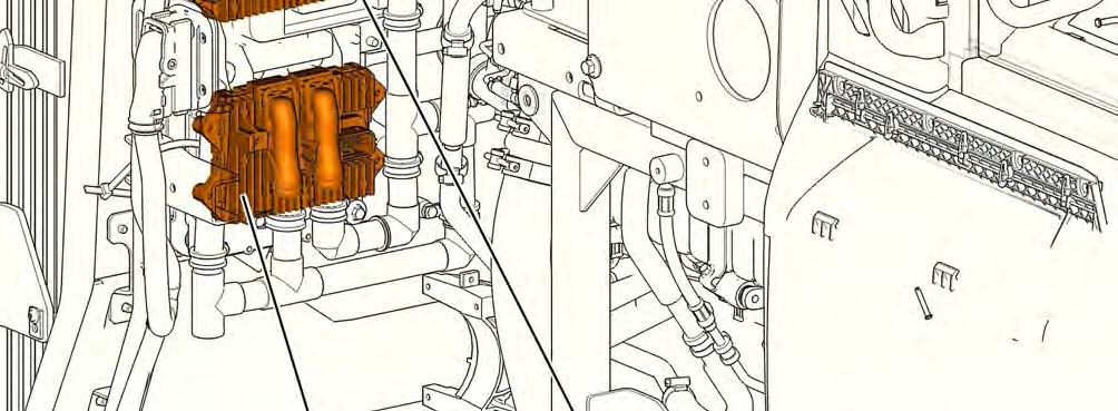

5. Unplug the connectors from the E-ECU and loosen the cable harness clamps.
6. Replace the E-ECU.
7. Plug in the connectors and install the cable harness clamps.
8. Install the engine cover.
9. Turn on the voltage with the battery disconnector.
10. Finish the VCADS Pro operation 28423-3 MID 128 ECU, programming.
11. If read-out of parameters was not possible with the programming operation, then VCADS Pro operation 25438-3 NOx sensor, age compensation, reset must also be run.
12. Start the machine and check that there are no error messages.
13. Restore the machine.
Document Title: Function Group: Information Type: Date:
E-ECU, MID 128, changing pre-programmed ECU 200 Service Information 2014/5/5 0
Profile: WLO, L120G [GB]
E-ECU, MID 128, changing pre-programmed ECU
Op nbr 200-070
VCADS Pro VCADS Pro Service Tool
88890180 Interface
88890027 Cable
1. Place the machine in service position 1, see . 191 Service position
2. The new control unit has basically adjusted parameters for the machine. Connect VCADS Pro and read out customer parameters with operation 17030-3 Parameter, programming. If it is possible to read out customer parameters from the old control unit, save them on the job card.
3. Turn off the voltage with the battery disconnector.
4. Remove the engine cover on the right side.
5. Unplug the connectors from the E-ECU and loosen the cable harness clamps.
6. Replace the E-ECU.
7. Plug in the connectors and install the cable harness clamps.
8. Install the engine cover.
9. Turn on the voltage with the battery disconnector.
10. If customer parameters have been read out from the old control unit, they should be compared with the parameters in the new control unit.
Connect VCADS Pro and run operation 17030-3 Parameter, programming. Save all read parameters to job card.
Compare the parameter settings on the job cards.
Run the operation 17030-3 Parameter, programming and change customer parameters according to job cards for the old control unit.
11. Also run the operation 25438-3 NOx sensor, age compensation, reset.
12. Start the machine and check that there are no error messages.
13. Restore the machine.
Document Title: Function Group: Information Type: Date: VCADS Pro, Operations 200 Service Information 2014/5/5 0
Profile: WLO, L120G [GB]
VCADS Pro, Operations
The following VCADS Pro operations are available for function group 2. Operations used when changing or working on components are mandatory.
Tests
Operation Application
21006-3 Cylinder compression, test
23777-3 Fuel System, Check
23712-3 Injectors shut off, manual
Used when there is a suspicion of malfunction and/or in case of abnormal values/readings.
This test indicates if there is any deviation in compression in any cylinder in relation to the other cylinders.
As a first check this operation is both easy and fast to perform instead of an actual compression test.
Used when there is a suspicion of malfunction and/or in case of abnormal values/readings.
Used when there is a suspicion of malfunction and/or in case of abnormal values/readings.
25410-3 Air pump exhaust aftertreatment, test Used when there is a suspicion of malfunction and/or in case of abnormal values/readings.
25411-3 Burner exhaust aftertreatment, test Used when there is a suspicion of malfunction and/or in case of abnormal values/readings.
25433-3 Fuel system exhaust aftertreatment, bleeding The operation is used after work has been performed on the fuel system to ensure that there is no air in the EATS fuel system.
25438-3, Nox sensor, age compensation, reset The operation is used to reset the NO age compensation value stored in MID 128 Engine control unit, either when the NO -sensor has been replaced with a new one or the MID 128 Engine control unit has been replaced with a new one, and it is not possible to read out the values from the old control unit.
25440-3 Fuel pressure, exhaust aftertreatment system, test
The operation is used to test the fuel system for the exhaust aftertreatment system.
25456-3 Exhaust aftertreatment diagnostics Used to test components in the exhaust aftertreatment system.
25457-3 Diesel Particulate Filter Service Regeneration See 254 Perform a service regeneration
26385-3 Reversible cooling fan, test When there is a suspicion of malfunction and/or in case of abnormal values/ readings.
27102-3 Accelerator pedal, test In case of abnormal values/readings.
28407-3 Sensor values, monitoring When there is a suspicion of malfunction and/or in case of abnormal values/ readings.
Programming
Operation Application
25801-3 MID 233 Control unit, programming When changing ACM or only reprogramming. See 254 ACM, replacing, non-programmed
28423-3 MID 128 ECU, programming When changing ACM or only reprogramming. See 200 E-ECU, MID 128, changing non-programmed ECU
Document Title: Function Group: Information Type: Date: Engine belts, replacing 200 Service Information 2014/5/5 0
Profile: WLO, L120G [GB]
Engine belts, replacing
Op nbr 200-200
1. Place the machine in service position according to 191 Service position
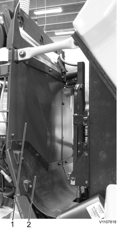
2. Remove the left protective plate. Remove the plastic protection on the right and left side.
3. Remove the AC-belt and the alternator belt.

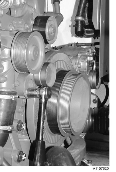
Loosen the tensioning pulley and remove the belts
4. Install new alternator belt and AC-belt.
5. Install left and right plastic protection. Install the left protective plate.
6. Restore the machine.
Document Title: Function Group: Information Type: Date:
Compression test 210 Service Information 2014/5/5 0
Profile: WLO, L120G [GB]
Compression test
Op nbr 210-002
9988539 Pressure gauge
88800070 Spanner
88830197 Rotation tool
88830205 Adapter
88830206 Counterhold
This operation also includes required tools and times for applicable parts of the following operations: 214 Valves, adjusting
NOTICE
Maintain greatest possible cleanliness when working on the fuel system.
1. Place the machine in service position 1, see: 191 Service position
2. Open the engine hood.
3. NOTICE
Plug all pipes, hoses and connections when removing.
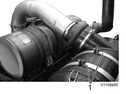
4. Remove the inlet pipe (4 clamps).

5. Mark the position of the exhaust pipe. Remove the exhaust pipe (2 clamps).
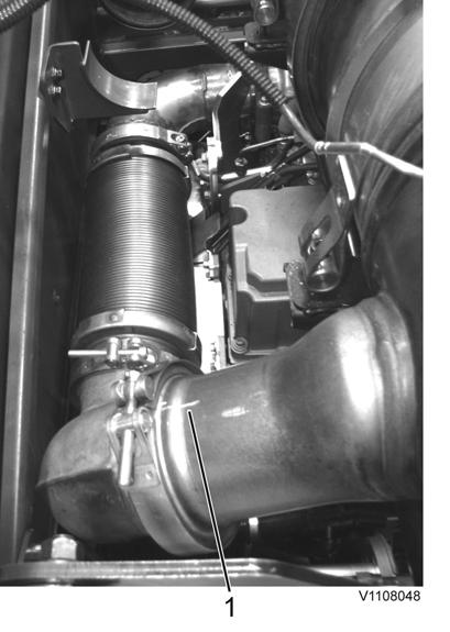
2
1. Marking, example
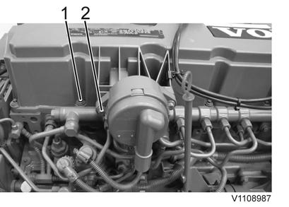
6. Loosen the attaching bolts (4 pcs.) for the DPF. Lift up/place the DPF in service position.

1. Attaching bolts
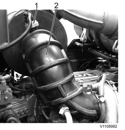
7. Unplug the connector and remove the hose between the air cleaner and the turbo (2 clamps).
8. Remove the bracket for the air cleaner (2 clamps). Remove the air cleaner.
9. Remove the hose clamps (2 pcs.) and hoses for the crankcase ventilation. Remove the crankcase ventilation (2 bolts) and the valve cover (15 bolts).
Thanks very much for your reading, Want to get more information, Please click here, Then get the complete manual

NOTE: please download the PDF document first, and then click on it.